

Page 1

General-Purpose AC Servo
J2-Super Series
Built-In Positioning Function
MODEL
MR-J2S- CP
SERVO AMPLIFIER
INSTRUCTION MANUAL
G
Page 2
Safety Instructions
(Always read these instructions before using the equipment.)
Do not attempt to install, operate, maintain or inspect the servo amplifier and servo motor until you have read
through this Instruction Manual, Installation guide, Servo motor Instruction Manual and appended documents
carefully and can use the equipment correctly. Do not use the servo amplifier and servo motor until you have a
full knowledge of the equipment, safety information and instructions.
In this Instruction Manual, the safety instruction levels are classified into "WARNING" and "CAUTION".
WARNING
CAUTION
Indicates that incorrect handling may cause hazardous conditions,
resulting in death or severe injury.
Indicates that incorrect handling may cause hazardous conditions,
resulting in medium or slight injury to personnel or may cause physical
damage.
Note that the CAUTION level may lead to a serious consequence according to conditions. Please follow the
instructions of both levels because they are important to personnel safety.
What must not be done and what must be done are indicated by the following diagrammatic symbols:
: Indicates what must not be done. For example, "No Fire" is indicated by
: Indicates what must be done. For example, grounding is indicated by
In this Instruction Manual, instructions at a lower level than the above, instructions for other functions, and so
on are classified into "POINT".
After reading this installation guide, always keep it accessible to the operator.
.
.
A - 1
Page 3

1. To prevent electric shock, note the following:
WARNING
Before wiring or inspection, turn off the power and wait for 15 minutes or more until the charge lamp turns
off. Then, confirm that the voltage between P and N is safe with a voltage tester and others. Otherwise, an
electric shock may occur. In addition, always confirm from the front of the servo amplifier, whether the
charge lamp is off or not.
Connect the servo amplifier and servo motor to ground.
Any person who is involved in wiring and inspection should be fully competent to do the work.
Do not attempt to wire the servo amplifier and servo motor until they have been installed. Otherwise, you
may get an electric shock.
Operate the switches with dry hand to prevent an electric shock.
The cables should not be damaged, stressed, loaded, or pinched. Otherwise, you may get an electric shock.
During power-on or operation, do not open the front cover of the servo amplifier. You may get an electric
shock.
Do not operate the servo amplifier with the front cover removed. High-voltage terminals and charging area
are exposed and you may get an electric shock.
Except for wiring or periodic inspection, do not remove the front cover even of the servo amplifier if the
power is off. The servo amplifier is charged and you may get an electric shock.
2. To prevent fire, note the following:
CAUTION
Install the servo amplifier, servo motor and regenerative resistor on incombustible material. Installing them
directly or close to combustibles will lead to a fire.
Always connect a magnetic contactor (MC) between the main circuit power supply and L1, L2, and L3 of
the servo amplifier, and configure the wiring to be able to shut down the power supply on the side of the
servo amplifier’s power supply. If a magnetic contactor (MC) is not connected, continuous flow of a large
current may cause a fire when the servo amplifier malfunctions.
When a regenerative resistor is used, use an alarm signal to switch main power off. Otherwise, a
regenerative transistor fault or the like may overheat the regenerative resistor, causing a fire.
3. To prevent injury, note the follow
CAUTION
Only the voltage specified in the Instruction Manual should be applied to each terminal, Otherwise, a
burst, damage, etc. may occur.
Connect the terminals correctly to prevent a burst, damage, etc.
Ensure that polarity ( , ) is correct. Otherwise, a burst, damage, etc. may occur.
Take safety measures, e.g. provide covers, to prevent accidental contact of hands and parts (cables, etc.)
with the servo amplifier heat sink, regenerative resistor, servo motor, etc.since they may be hot while
power is on or for some time after power-off. Their temperatures may be high and you may get burnt or a
parts may damaged.
During operation, never touch the rotating parts of the servo motor. Doing so can cause injury.
A - 2
Page 4
4. Additional instructions
The following instructions should also be fully noted. Incorrect handling may cause a fault, injury, electric
shock, etc.
(1) Transportation and installation
CAUTION
Transport the products correctly according to their weights.
Stacking in excess of the specified number of products is not allowed.
Do not carry the servo motor by the cables, shaft or encoder.
Do not hold the front cover to transport the servo amplifier. The servo amplifier may drop.
Install the servo amplifier in a load-bearing place in accordance with the Instruction Manual.
Do not climb or stand on servo equipment. Do not put heavy objects on equipment.
The servo amplifier and servo motor must be installed in the specified direction.
Leave specified clearances between the servo amplifier and control enclosure walls or other equipment.
Do not install or operate the servo amplifier and servo motor which has been damaged or has any parts
missing.
Provide adequate protection to prevent screws and other conductive matter, oil and other combustible
matter from entering the servo amplifier and servo motor.
Do not drop or strike servo amplifier or servo motor. Isolate from all impact loads.
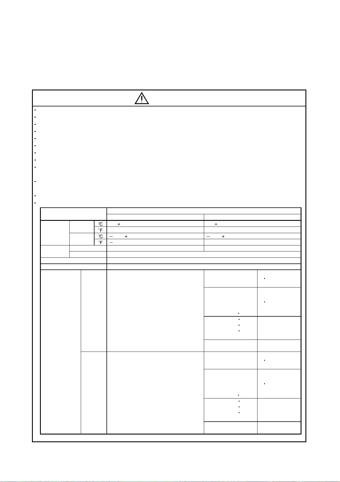
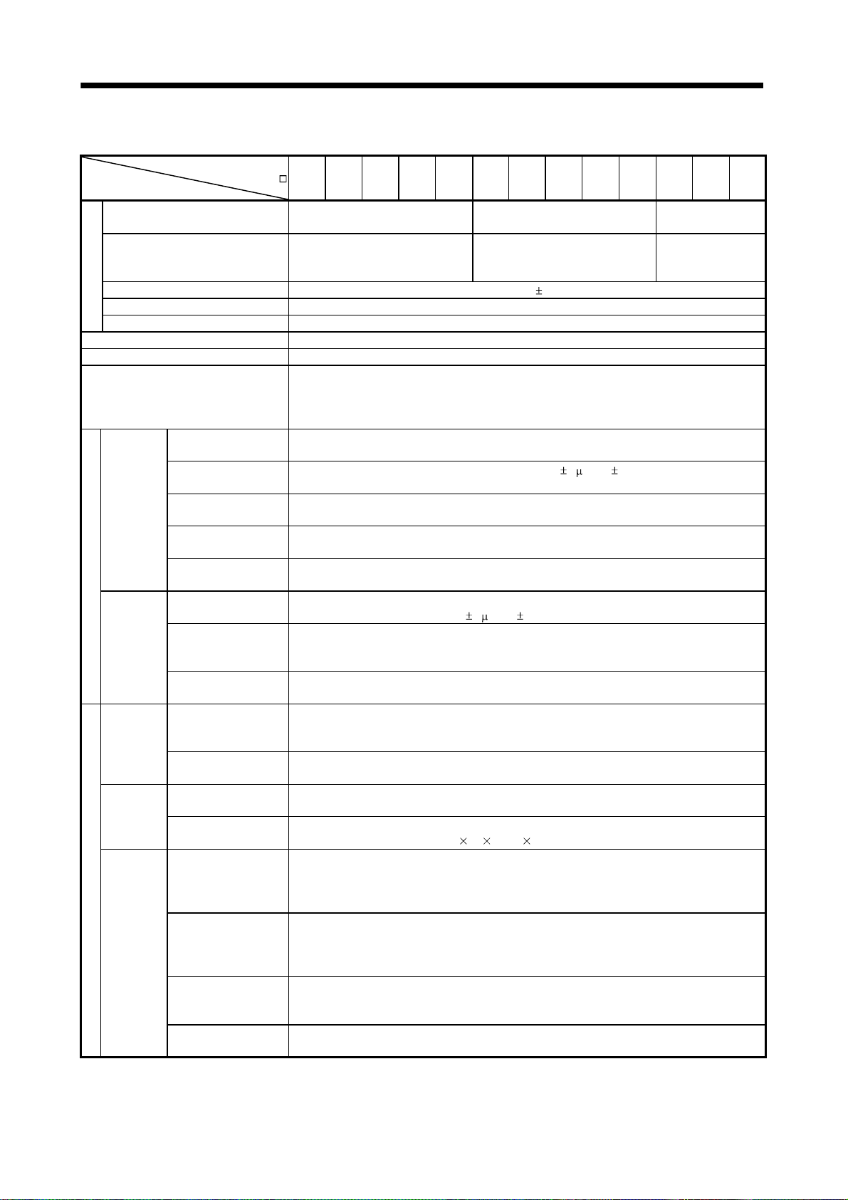
When you keep or use it, please fulfill the following environmental conditions.
Conditions
[ ] 0 to 55 (non-freezing) 0 to 40 (non-freezing)
Ambient
temperature
[ ] 20 to 65 (non-freezing) 15 to 70 (non-freezing)
Ambient
In operation 90%RH or less (non-condensing) 80%RH or less (non-condensing)
humidity
Ambience Indoors (no direct sunlight) Free from corrosive gas, flammable gas, oil mist, dust and dirt
Altitude Max. 1000m (3280 ft) above sea level
HC-KFS Series
HC-SFS81
HC-SFS121 201
(Note)
Vibration
HC-KFS Series
HC-SFS81
HC-SFS121 201
Note. Except the servo motor with reduction gear.
Environment
In
operation
In storage
In storage 90%RH or less (non-condensing)
[
] 32 to 131 (non-freezing) 32 to 104 (non-freezing)
[ ] 4 to 149 (non-freezing) 5 to 158 (non-freezing)
2
[m/s
] 5.9 or less
2
] 19.4 or less
[ft/s
Servo amplifier Servo motor
HC-MFS Series
HC-UFS13 to 73
HC-SFS52 to 152
HC-SFS53 to 153
HC-RFS Series
HC-UFS 72
HC-SFS202
HC-SFS203
HC-UFS202
HC-SFS301
HC-MFS Series
HC-UFS 13 to 73
HC-SFS52 to 152
HC-SFS53 to 153
HC-RFS Series
HC-UFS 72
HC-SFS202
HC-SFS203
HC-UFS202
HC-SFS301
152
352
353
152
352
353
X
X
X : 24.5
Y : 49
X : 24.5
Y : 29.4
X
X
X : 80
Y : 161
X : 80
Y : 96
Y : 49
Y : 24.5
Y : 161
Y : 80
A - 3
Page 5
CAUTION
Securely attach the servo motor to the machine. If attach insecurely, the servo motor may come off during
operation.
The servo motor with reduction gear must be installed in the specified direction to prevent oil leakage.
Take safety measures, e.g. provide covers, to prevent accidental access to the rotating parts of the servo
motor during operation.
Never hit the servo motor or shaft, especially when coupling the servo motor to the machine. The encoder
may become faulty.
Do not subject the servo motor shaft to more than the permissible load. Otherwise, the shaft may break.
When the equipment has been stored for an extended period of time, consult Mitsubishi.
(2) Wiring
CAUTION
Wire the equipment correctly and securely. Otherwise, the servo motor may misoperate.
Do not install a power capacitor, surge absorber or radio noise filter (FR-BIF option) between the servo
motor and servo amplifier.
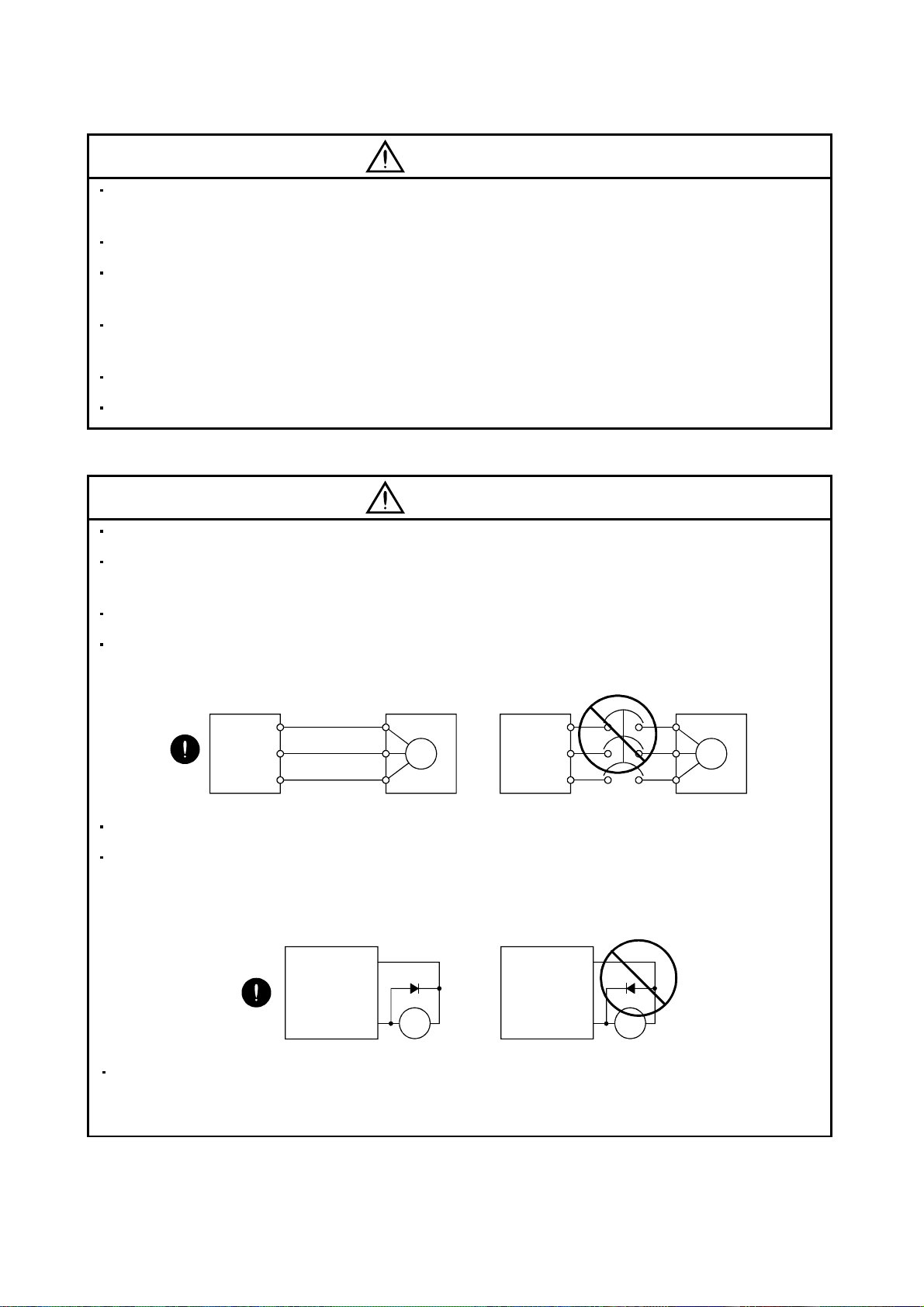
Connect the output terminals (U, V, W) correctly. Otherwise, the servo motor will operate improperly.
Connect the servo motor power terminal (U, V, W) to the servo motor power input terminal (U, V, W)
directly. Do not let a magnetic contactor, etc. intervene.
Servo amplifier
U
V
W
Servo motor
U
V
W
U
M
V
W
Servo motorServo amplifier
U
V
M
W
Do not connect AC power directly to the servo motor. Otherwise, a fault may occur.
The surge absorbing diode installed on the DC output signal relay of the servo amplifier must be wired in
the specified direction. Otherwise, the emergency stop (EMG) and other protective circuits may not
operate.
Servo amplifier Servo amplifier
COM
(24VDC)
Control
output
signal
RA
COM
(24VDC)
Control
output
signal
RA
When the cable is not tightened enough to the terminal block (connector), the cable or terminal block
(connector) may generate heat because of the poor contact. Be sure to tighten the cable with specified
torque.
A - 4
Page 6
(3) Test run adjustment
CAUTION
Before operation, check the parameter settings. Improper settings may cause some machines to perform
unexpected operation.
The parameter settings must not be changed excessively. Operation will be insatiable.
(4) Usage
CAUTION
Provide an external emergency stop circuit to ensure that operation can be stopped and power switched
off immediately.
Any person who is involved in disassembly and repair should be fully competent to do the work.
Before resetting an alarm, make sure that the run signal of the servo amplifier is off to prevent an accident.
A sudden restart is made if an alarm is reset with the run signal on.
Do not modify the equipment.
Use a noise filter, etc. to minimize the influence of electromagnetic interference, which may be caused by
electronic equipment used near the servo amplifier.
Burning or breaking a servo amplifier may cause a toxic gas. Do not burn or break a servo amplifier.
Use the servo amplifier with the specified servo motor.
The electromagnetic brake on the servo motor is designed to hold the motor shaft and should not be used
for ordinary braking.
For such reasons as service life and mechanical structure (e.g. where a ballscrew and the servo motor are
coupled via a timing belt), the electromagnetic brake may not hold the motor shaft. To ensure safety,
install a stopper on the machine side.
(5) Corrective actions
CAUTION
When it is assumed that a hazardous condition may take place at the occur due to a power failure or a
product fault, use a servo motor with electromagnetic brake or an external brake mechanism for the
purpose of prevention.
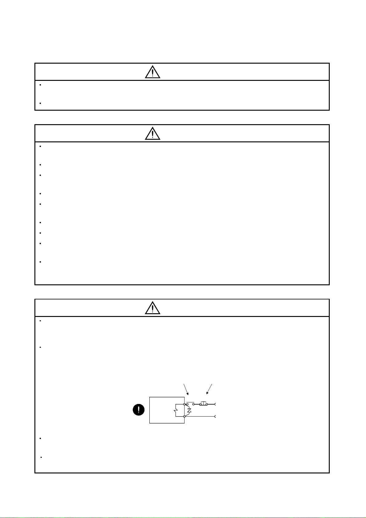
Configure the electromagnetic brake circuit so that it is activated not only by the servo amplifier signals but
also by an external forced stop (EMG).
Contacts must be open when
servo-off, when an trouble (ALM)
and when an electromagnetic brake
interlock (MBR).
Servo motor
Circuit must be
opened during
forced stop (EMG).
EMGRA
24VDC
Electromagnetic brake
When any alarm has occurred, eliminate its cause, ensure safety, and deactivate the alarm before
restarting operation.
When power is restored after an instantaneous power failure, keep away from the machine because the
machine may be restarted suddenly (design the machine so that it is secured against hazard if restarted).
A - 5
Page 7
(6) Maintenance, inspection and parts replacement
CAUTION
With age, the electrolytic capacitor of the servo amplifier will deteriorate. To prevent a secondary accident
due to a fault, it is recommended to replace the electrolytic capacitor every 10 years when used in general
environment.
Please consult our sales representative.
(7) General instruction
To illustrate details, the equipment in the diagrams of this Specifications and Instruction Manual may have
been drawn without covers and safety guards. When the equipment is operated, the covers and safety
guards must be installed as specified. Operation must be performed in accordance with this Specifications
and Instruction Manual.
About processing of waste
When you discard servo amplifier, a battery (primary battery), and other option articles, please follow the law of
each country (area).
FOR MAXIMUM SAFETY
These products have been manufactured as a general-purpose part for general industries, and have not
been designed or manufactured to be incorporated in a device or system used in purposes related to
human life.
Before using the products for special purposes such as nuclear power, electric power, aerospace,
medicine, passenger movement vehicles or underwater relays, contact Mitsubishi.
These products have been manufactured under strict quality control. However, when installing the product
where major accidents or losses could occur if the product fails, install appropriate backup or failsafe
functions in the system.
EEP-ROM life
The number of write times to the EEP-ROM, which stores parameter settings, etc., is limited to 100,000. If
the total number of the following operations exceeds 100,000, the servo amplifier and/or converter unit may
fail when the EEP-ROM reaches the end of its useful life.
Write to the EEP-ROM due to parameter setting changes
Home position setting in the absolute position detection system
Write to the EEP-ROM due to device changes
Write to the EEP-ROM due to point table changes
PRECAUTIONS FOR CHOOSING THE PRODUCTS
Mitsubishi will not be held liable for damage caused by factors found not to be the cause of Mitsubishi;
machine damage or lost profits caused by faults in the Mitsubishi products; damage, secondary damage,
accident compensation caused by special factors unpredictable by Mitsubishi; damages to products other
than Mitsubishi products; and to other duties.
A - 6
Page 8

COMPLIANCE WITH EC DIRECTIVES
1. WHAT ARE EC DIRECTIVES?
The EC directives were issued to standardize the regulations of the EU countries and ensure smooth
distribution of safety-guaranteed products. In the EU countries, the machinery directive (effective in
January, 1995), EMC directive (effective in January, 1996) and low voltage directive (effective in January,
1997) of the EC directives require that products to be sold should meet their fundamental safety
requirements and carry the CE marks (CE marking). CE marking applies to machines and equipment
into which servo amplifiers have been installed.
(1) EMC directive
The EMC directive applies not to the servo units alone but to servo-incorporated machines and
equipment. This requires the EMC filters to be used with the servo-incorporated machines and
equipment to comply with the EMC directive. For specific EMC directive conforming methods, refer to
the EMC Installation Guidelines (IB(NA)67310).
(2) Low voltage directive
The low voltage directive applies also to servo units alone. Hence, they are designed to comply with
the low voltage directive.
This servo is certified by TUV, third-party assessment organization, to comply with the low voltage
directive.
(3) Machine directive
Not being machines, the servo amplifiers need not comply with this directive.
2. PRECAUTIONS FOR COMPLIANCE
(1) Servo amplifiers and servo motors used
Use the servo amplifiers and servo motors which comply with the standard model.
Servo amplifier series :MR-J2S-10CP to MR-J2S-700CP
MR-J2S-10CP1 to MR-J2S40CP1
Servo motor series :HC-KFS
HC-MFS
HC-SFS
HC-RFS
HC-UFS
HA-LFS
HC-LFS
(2) Configuration
Control box
Reinforced
insulating type
Reinforced
insulating
transformer
No-fuse
breaker
NFB
Magnetic
contactor
MC
24VDC
power
supply
Servo
amplifier
Servo
motor
M
(3) Environment
Operate the servo amplifier at or above the contamination level 2 set forth in IEC60664-1. For this
purpose, install the servo amplifier in a control box which is protected against water, oil, carbon, dust,
dirt, etc. (IP54).
A - 7
Page 9
(4) Power supply
(a) Operate the servo amplifier to meet the requirements of the overvoltage category II set forth in
IEC60664-1. For this purpose, a reinforced insulating transformer conforming to the IEC or EN
Standard should be used in the power input section.
(b) When supplying interface power from external, use a 24VDC power supply which has been
insulation-reinforced in I/O.
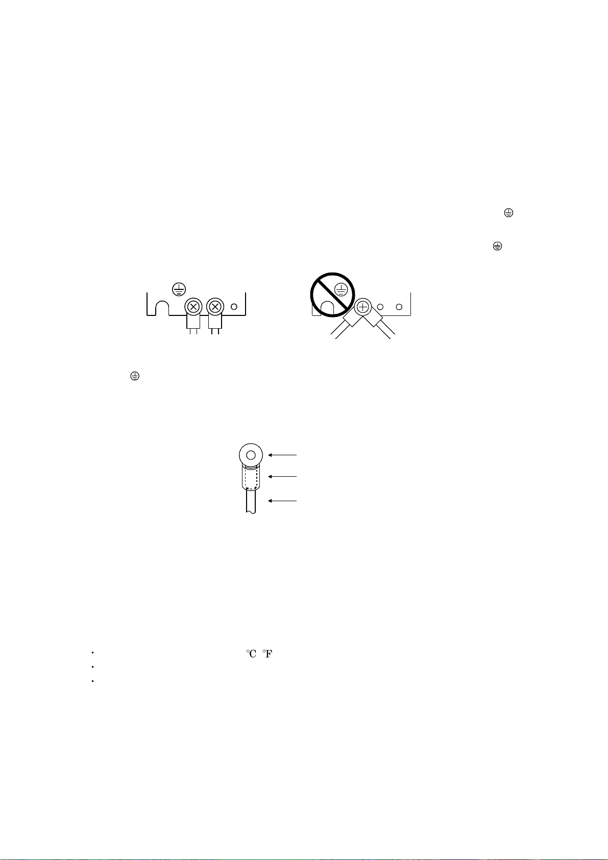
(5) Grounding
(a) To prevent an electric shock, always connect the protective earth (PE) terminals (marked
servo amplifier to the protective earth (PE) of the control box.
) of the
(b) Do not connect two ground cables to the same protective earth (PE) terminal (marked ). Always
connect the cables to the terminals one-to-one.
PE terminals
PE terminals
(c) If a leakage current breaker is used to prevent an electric shock, the protective earth (PE) terminals
(marked
) of the servo amplifier must be connected to the corresponding earth terminals.
(6) Wiring
(a) The cables to be connected to the terminal block of the servo amplifier must have crimping
terminals provided with insulating tubes to prevent contact with adjacent terminals.
Crimping terminal
Insulating tube
Cable
(b) Use the servo motor side power connector which complies with the EN Standard. The EN Standard
compliant power connector sets are available from us as options. (Refer to section 14.1.4)
(7) Auxiliary equipment and options
(a) The circuit breaker and magnetic contactor used should be the EN or IEC standard-compliant
products of the models described in section 14.2.2.
(b) The sizes of the cables described in section 14.2.1 meet the following requirements. To meet the
other requirements, follow Table 5 and Appendix C in EN60204-1.
Ambient temperature: 40 (104) [ ( )]
Sheath: PVC (polyvinyl chloride)
Installed on wall surface or open table tray
(c) Use the EMC filter for noise reduction.
(8) Performing EMC tests
When EMC tests are run on a machine/device into which the servo amplifier has been installed, it
must conform to the electromagnetic compatibility (immunity/emission) standards after it has
satisfied the operating environment/electrical equipment specifications.
For the other EMC directive guidelines on the servo amplifier, refer to the EMC Installation
Guidelines (IB(NA)67310).
A - 8
Page 10
CONFORMANCE WITH UL/C-UL STANDARD
(1) Servo amplifiers and servo motors used
Use the servo amplifiers and servo motors which comply with the standard model.
Servo amplifier series :MR-J2S-10CP to MR-J2S-700CP
MR-J2S-10CP1 to MR-J2S-40CP1
Servo motor series :HC-KFS
HC-MFS
HC-SFS
HC-RFS
HC-UFS
HA-LFS
HC-LFS
(2) Installation
Install a cooling fan of 100CFM (2.8m
provide cooling of at least equivalent capability.
(3) Short circuit rating
This servo amplifier conforms to the circuit whose peak current is limited to 5000A or less. Having
been subjected to the short-circuit tests of the UL in the alternating-current circuit, the servo
amplifier conforms to the above circuit.
(4) Capacitor discharge time
The capacitor discharge time is as listed below. To ensure safety, do not touch the charging section for
15 minutes after power-off.
3
/min) air flow 4 [in] (10.16 [cm]) above the servo amplifier or
Servo amplifier Discharge time [min]
MR-J2S-10CP(1) 20CP(1) 1
MR-J2S-40CP(1) 60CP 2
MR-J2S-70CP to 350CP 3
MR-J2S-500CP 700CP 5
(5) Options and auxiliary equipment
Use UL/C-UL standard-compliant products.
(6) Attachment of a servo motor
For the flange size of the machine side where the servo motor is installed, refer to “CONFORMANCE
WITH UL/C-UL STANDARD” in the Servo Motor Instruction Manual.
(7) About wiring protection
For installation in United States, branch circuit protection must be provided, in accordance with the
National Electrical Code and any applicable local codes.
For installation in Canada, branch circuit protection must be provided, in accordance with the Canada
Electrical Code and any applicable provincial codes.
<<About the manuals>>
This Instruction Manual and the MELSERVO Servo Motor Instruction Manual are required if you use
the MR-J2S-CP for the first time. Always purchase them and use the MR-J2S-CP safely.
Relevant manuals
Manual name Manual No.
MELSERVO-J2-Super Series To Use the AC Servo Safely IB(NA)0300010
MELSERVO Servo Motor Instruction Manual SH(NA)3181
EMC Installation Guidelines IB(NA)67310
A - 9
Page 11

MEMO
A - 10
Page 12

CONTENTS
1. FUNCTIONS AND CONFIGURATION 1- 1 to 1-26
1.1 Introduction.............................................................................................................................................. 1- 1
1.1.1 Function block diagram ................................................................................................................... 1- 1
1.1.2 System configuration........................................................................................................................ 1- 4
1.1.3 I/O devices ......................................................................................................................................... 1- 9
1.2 Servo amplifier standard specifications ............................................................................................... 1-10
1.3 Function list ............................................................................................................................................ 1-12
1.4 Model code definition ............................................................................................................................. 1-13
1.5 Combination with servo motor .............................................................................................................. 1-14
1.6 Structure.................................................................................................................................................. 1-15
1.6.1 Part names ....................................................................................................................................... 1-15
1.6.2 Removal and reinstallation of the front cover .............................................................................. 1-19
1.7 Servo system with auxiliary equipment............................................................................................... 1-21
2. INSTALLATION 2- 1 to 2- 4
2.1 Environmental conditions ...................................................................................................................... 2- 1
2.2 Installation direction and clearances ....................................................................................................2- 2
2.3 Keep out foreign materials ..................................................................................................................... 2- 3
2.4 Cable stress .............................................................................................................................................. 2- 4
3. SIGNALS AND WIRING 3- 1 to 3-42
3.1 Standard connection example ................................................................................................................ 3- 2
3.2 Internal connection diagram of servo amplifier ................................................................................... 3- 3
3.3 I/O signals................................................................................................................................................. 3- 4
3.3.1 Connectors and signal arrangements ............................................................................................. 3- 4
3.3.2 Signal (devices) explanations ..........................................................................................................3- 5
3.4 Detailed description of signals (devices) .............................................................................................. 3-13
3.4.1 Forward rotation start
3.4.2 Movement finish
3.4.3 Override ............................................................................................................................................ 3-16
3.4.4 Torque limit...................................................................................................................................... 3-17
3.5 Alarm occurrence timing chart .............................................................................................................3-19
3.6 Interfaces .................................................................................................................................................3-20
3.6.1 Common line .................................................................................................................................... 3-20
3.6.2 Detailed description of the interfaces ............................................................................................ 3-21
3.7 Input power supply circuit..................................................................................................................... 3-25
3.7.1 Connection example ........................................................................................................................ 3-25
3.7.2 Terminals.......................................................................................................................................... 3-27
3.7.3 Power-on sequence........................................................................................................................... 3-28
3.8 Connection of servo amplifier and servo motor ................................................................................... 3-29
3.8.1 Connection instructions ..................................................................................................................3-29
3.8.2 Connection diagram ........................................................................................................................ 3-29
3.8.3 I/O terminals .................................................................................................................................... 3-31
3.9 Servo motor with electromagnetic brake ............................................................................................. 3-33
Reverse rotation start Temporary stop/restart................................. 3-13
Rough match In position ............................................................................... 3-14
1
Page 13

3.10 Grounding ............................................................................................................................................. 3-37
3.11 Servo amplifier terminal block (TE2) wiring method....................................................................... 3-38
3.11.1 For the servo amplifier produced later than Jan. 2006 ............................................................. 3-38
3.11.2 For the servo amplifier produced earlier than Dec. 2005 .......................................................... 3-40
3.12 Instructions for the 3M connector....................................................................................................... 3-42
4. OPERATION 4- 1 to 4-46
4.1 When switching power on for the first time.......................................................................................... 4- 1
4.1.1 Pre-operation checks ........................................................................................................................ 4- 1
4.1.2 Startup ............................................................................................................................................... 4- 2
4.2 Automatic operation mode...................................................................................................................... 4- 5
4.2.1 What is automatic operation mode? ............................................................................................... 4- 5
4.2.2 Absolute value command system .................................................................................................... 4- 8
4.2.3 Incremental value command system ............................................................................................. 4-10
4.2.4 Absolute value command/incremental value command specifying system ...............................4-12
4.2.5 Automatic operation timing chart.................................................................................................. 4-14
4.2.6 Automatic continuous operation .................................................................................................... 4-15
4.3 Manual operation mode .........................................................................................................................4-22
4.3.1 Jog operation .................................................................................................................................... 4-22
4.3.2 Manual pulse generator operation.................................................................................................4-24
4.4 Manual home position return mode ..................................................................................................... 4-26
4.4.1 Outline of home position return ..................................................................................................... 4-26
4.4.2 Dog type home position return ....................................................................................................... 4-28
4.4.3 Count type home position return ................................................................................................... 4-30
4.4.4 Data setting type home position return ........................................................................................ 4-31
4.4.5 Stopper type home position return ................................................................................................4-32
4.4.6 Home position ignorance (servo-on position defined as home position)..................................... 4-34
4.4.7 Dog type rear end reference home position return....................................................................... 4-35
4.4.8 Count type front end reference home position return.................................................................. 4-36
4.4.9 Dog cradle type home position return ...........................................................................................4-37
4.4.10 Home position return automatic return function....................................................................... 4-38
4.4.11 Automatic positioning function to the home position ................................................................4-39
4.5 Absolute position detection system....................................................................................................... 4-40
4.6 Serial communication operation ........................................................................................................... 4-43
4.6.1 Positioning operation in accordance with point tables ................................................................ 4-43
4.6.2 Positioning operation....................................................................................................................... 4-44
4.6.3 Multidrop system............................................................................................................................. 4-44
4.6.4 Group designation ........................................................................................................................... 4-45
5. PARAMETERS 5- 1 to 5-24
5.1 Parameter list .......................................................................................................................................... 5- 1
5.1.1 Parameter write inhibit ................................................................................................................... 5- 1
5.1.2 List ..................................................................................................................................................... 5- 2
5.2 Detailed explanation ..............................................................................................................................5-19
5.2.1 Electronic gear .................................................................................................................................5-19
5.2.2 Changing the status display screen............................................................................................... 5-20
5.2.3 S-pattern acceleration/deceleration ............................................................................................... 5-21
5.2.4 Analog output................................................................................................................................... 5-21
2
Page 14

5.2.5 Changing the stop pattern using a limit switch ........................................................................... 5-24
5.2.6 Alarm history clear.......................................................................................................................... 5-24
5.2.7 Rough match output ........................................................................................................................ 5-24
5.2.8 Software limit................................................................................................................................... 5-24
6. MR Configurator (SERVO CONFIGURATION SOFTWARE) 6- 1 to 6-20
6.1 Specifications ...........................................................................................................................................6- 1
6.2 System configuration............................................................................................................................... 6- 1
6.3 Station setting.......................................................................................................................................... 6- 3
6.4 Parameters ............................................................................................................................................... 6- 4
6.5 Point table ................................................................................................................................................ 6- 6
6.6 Device assignment method ..................................................................................................................... 6- 8
6.7 Test operation .........................................................................................................................................6-12
6.7.1 Jog operation .................................................................................................................................... 6-12
6.7.2 Positioning operation....................................................................................................................... 6-14
6.7.3 Motor-less operation ........................................................................................................................ 6-16
6.7.4 Output signal (DO) forced output ..................................................................................................6-17
6.7.5 Single-step feed ................................................................................................................................ 6-18
6.8 Alarm history ..........................................................................................................................................6-19
7. DISPLAY AND OPERATION 7- 1 to 7-26
7.1 Display flowchart..................................................................................................................................... 7- 1
7.2 Status display .......................................................................................................................................... 7- 2
7.2.1 Display transition ............................................................................................................................. 7- 2
7.2.2 Display examples .............................................................................................................................. 7- 3
7.2.3 Status display list ............................................................................................................................. 7- 4
7.3 Diagnosis mode ........................................................................................................................................ 7- 5
7.3.1 Display transition ............................................................................................................................. 7- 5
7.3.2 Diagnosis mode list........................................................................................................................... 7- 6
7.4 Alarm mode .............................................................................................................................................. 7- 8
7.4.1 Display transition ............................................................................................................................. 7- 8
7.4.2 Alarm mode list................................................................................................................................. 7- 9
7.5 Point table mode ..................................................................................................................................... 7-11
7.5.1 Point table transition ...................................................................................................................... 7-11
7.5.2 Point table mode setting screen sequence..................................................................................... 7-12
7.5.3 Operation method ............................................................................................................................ 7-13
7.6 Parameter mode ..................................................................................................................................... 7-15
7.6.1 Parameter mode transition............................................................................................................. 7-15
7.6.2 Operation example .......................................................................................................................... 7-16
7.7 External I/O signal display.................................................................................................................... 7-18
7.8 Output signal (DO) forced output ......................................................................................................... 7-19
7.9 Test operation mode ............................................................................................................................... 7-20
7.9.1 Mode change..................................................................................................................................... 7-20
7.9.2 Jog operation .................................................................................................................................... 7-21
7.9.3 Positioning operation....................................................................................................................... 7-22
7.9.4 Motor-less operation ........................................................................................................................ 7-23
7.10 Teaching function ................................................................................................................................. 7-24
7.10.1 Preparations for teaching .............................................................................................................7-24
3
Page 15

7.10.2 Position data setting method........................................................................................................ 7-25
8. GENERAL GAIN ADJUSTMENT 8- 1 to 8-12
8.1 Different adjustment methods ............................................................................................................... 8- 1
8.1.1 Adjustment on a single servo amplifier.......................................................................................... 8- 1
8.1.2 Adjustment using MR Configurator (servo configuration software) ........................................... 8- 2
8.2 Auto tuning .............................................................................................................................................. 8- 3
8.2.1 Auto tuning mode .............................................................................................................................8- 3
8.2.2 Auto tuning mode operation ............................................................................................................ 8- 4
8.2.3 Adjustment procedure by auto tuning............................................................................................ 8- 5
8.2.4 Response level setting in auto tuning mode .................................................................................. 8- 6
8.3 Manual mode 1 (simple manual adjustment) ....................................................................................... 8- 7
8.3.1 Operation of manual mode 1 ...........................................................................................................8- 7
8.3.2 Adjustment by manual mode 1 ....................................................................................................... 8- 7
8.4 Interpolation mode ................................................................................................................................. 8-10
8.5 Differences in auto tuning between MELSERVO-J2 and MELSERVO-J2-Super .......................... 8-11
8.5.1 Response level setting ..................................................................................................................... 8-11
8.5.2 Auto tuning selection....................................................................................................................... 8-11
9. SPECIAL ADJUSTMENT FUNCTIONS 9- 1 to 9-10
9.1 Function block diagram .......................................................................................................................... 9- 1
9.2 Machine resonance suppression filter ................................................................................................... 9- 1
9.3 Adaptive vibration suppression control................................................................................................. 9- 3
9.4 Low-pass filter ......................................................................................................................................... 9- 4
9.5 Gain changing function........................................................................................................................... 9- 5
9.5.1 Applications ....................................................................................................................................... 9- 5
9.5.2 Function block diagram ................................................................................................................... 9- 5
9.5.3 Parameters ........................................................................................................................................ 9- 6
9.5.4 Gain changing operation.................................................................................................................. 9- 8
10. INSPECTION 10- 1 to 10- 2
11. TROUBLESHOOTING 11- 1 to 11- 10
11.1 Trouble at start-up ..............................................................................................................................11- 1
11.2 When alarm or warning has occurred ...............................................................................................11- 2
11.2.1 Alarms and warning list .............................................................................................................. 11- 2
11.2.2 Remedies for alarms..................................................................................................................... 11- 3
11.2.3 Remedies for warnings................................................................................................................. 11- 9
11.3 MR-DP60 external digital display error........................................................................................... 11-10
12. OUTLINE DIMENSION DRAWINGS 12- 1 to 12- 8
12.1 Servo amplifiers................................................................................................................................... 12- 1
12.2 Connectors............................................................................................................................................ 12- 6
4
Page 16

13. CHARACTERISTICS 13- 1 to 13- 8
13.1 Overload protection characteristics ................................................................................................... 13- 1
13.2 Power supply equipment capacity and generated loss .................................................................... 13- 2
13.3 Dynamic brake characteristics........................................................................................................... 13- 4
13.3.1 Dynamic brake operation............................................................................................................. 13- 4
13.3.2 The dynamic brake at the load inertia moment ........................................................................ 13- 6
13.4 Encoder cable flexing life .................................................................................................................... 13- 6
13.5 Inrush currents at power-on of main circuit and control circuit ....................................................13- 7
14. OPTIONS AND AUXILIARY EQUIPMENT 14- 1 to 14-50
14.1 Options.................................................................................................................................................. 14- 1
14.1.1 Regenerative options .................................................................................................................... 14- 1
14.1.2 FR-BU2 brake unit....................................................................................................................... 14- 9
14.1.3 Power regeneration converter ....................................................................................................14-15
14.1.4 Cables and connectors ................................................................................................................. 14-18
14.1.5 Junction terminal block (MR-TB20) .......................................................................................... 14-26
14.1.6 Maintenance junction card (MR-J2CN3TM) ............................................................................14-28
14.1.7 External digital display (MR-DP60) .......................................................................................... 14-30
14.1.8 Manual pulse generator (MR-HDP01) ...................................................................................... 14-32
14.1.9 Battery (MR-BAT, A6BAT)......................................................................................................... 14-33
14.2 Auxiliary equipment .......................................................................................................................... 14-34
14.2.1 Recommended wires.................................................................................................................... 14-34
14.2.2 Circuit breakers, fuses, magnetic contactors............................................................................ 14-36
14.2.3 Power factor improving reactors ................................................................................................ 14-36
14.2.4 Relays............................................................................................................................................ 14-37
14.2.5 Surge absorbers ...........................................................................................................................14-37
14.2.6 Noise reduction techniques......................................................................................................... 14-38
14.2.7 Leakage current breaker ............................................................................................................ 14-45
14.2.8 EMC filter.....................................................................................................................................14-47
14.2.9 Setting potentiometers for analog inputs.................................................................................. 14-50
15. COMMUNICATION FUNCTIONS 15- 1 to 15-40
15.1 Configuration ....................................................................................................................................... 15- 1
15.1.1 RS-422 configuration.................................................................................................................... 15- 1
15.1.2 RS-232C configuration ................................................................................................................. 15- 2
15.2 Communication specifications............................................................................................................ 15- 3
15.2.1 Communication overview............................................................................................................. 15- 3
15.2.2 Parameter setting......................................................................................................................... 15- 4
15.3 Protocol ................................................................................................................................................. 15- 5
15.4 Character codes ................................................................................................................................... 15- 7
15.5 Error codes ...........................................................................................................................................15- 8
15.6 Checksum ............................................................................................................................................. 15- 8
15.7 Time-out operation .............................................................................................................................. 15- 9
15.8 Retry operation ....................................................................................................................................15- 9
15.9 Initialization........................................................................................................................................ 15-10
15.10 Communication procedure example ...............................................................................................15-10
5
Page 17

15.11 Command and data No. list.............................................................................................................15-11
15.11.1 Read commands ......................................................................................................................... 15-11
15.11.2 Write commands ........................................................................................................................ 15-14
15.12 Detailed explanations of commands............................................................................................... 15-17
15.12.1 Data processing.......................................................................................................................... 15-17
15.12.2 Status display ............................................................................................................................ 15-19
15.12.3 Parameter................................................................................................................................... 15-20
15.12.4 External I/O signal statuses..................................................................................................... 15-22
15.12.5 Input devices ON/OFF ..............................................................................................................15-24
15.12.6 Disable/enable of I/O devices (DIO) ......................................................................................... 15-25
15.12.7 Input devices ON/OFF (test operation) ................................................................................... 15-26
15.12.8 Test operation mode .................................................................................................................. 15-27
15.12.9 Output signal pin ON/OFF output signal (DO) forced output ..............................................15-30
15.12.10 Alarm history ...........................................................................................................................15-31
15.12.11 Current alarm.......................................................................................................................... 15-32
15.12.12 Point table ................................................................................................................................ 15-33
15.12.13 Servo amplifier group designation.........................................................................................15-39
15.12.14 Software version ...................................................................................................................... 15-40
APPENDIX App- 1 to App- 4
App 1. Status indication block diagram .................................................................................................App- 1
App 2. Junction terminal block (MR-TB20) terminal block labels ...................................................... App- 2
App 3. Combination of servo amplifier and servo motor ...................................................................... App- 3
App 4. Change of connector sets to the RoHS compatible products .................................................... App- 4
6
Page 18

Optional Servo Motor Instruction Manual CONTENTS
The rough table of contents of the optional MELSERVO Servo Motor Instruction Manual is introduced
here for your reference. Note that the contents of the Servo Motor Instruction Manual are not included in
the Servo Amplifier Instruction Manual.
1. INTRODUCTION
2. INSTALLATION
3. CONNECTORS USED FOR SERVO MOTOR WIRING
4. INSPECTION
5. SPECIFICATIONS
6. CHARACTERISTICS
7. OUTLINE DIMENSION DRAWINGS
8. CALCULATION METHODS FOR DESIGNING
7
Page 19

MEMO
8
Page 20

1. FUNCTIONS AND CONFIGURATION
1. FUNCTIONS AND CONFIGURATION
1.1 Introduction
The MR-J2S-CP AC servo amplifier with built-in positioning functions is the MR-J2S-A general-purpose
AC servo amplifier which incorporate single-axis positioning functions. These functions perform
positioning operation by merely setting the position data (target positions), servo motor speeds,
acceleration and deceleration time constants, etc. to point tables as if setting them in parameters. The
servo amplifier is the most appropriate to configure a program-free, simple positioning system or to
simplify a system, for example.
There are 3 points of point tables as standard, and they can be increased up to 31 points by using the MR
Configurator (servo configuration software).
You can choose a configuration suitable for your purpose, e.g. simple positioning system using external
I/O signals (DI/O), operation using DI/O and RS-422 serial communication, or multi drop operation using
RS-422 serial communication.
All servo motors are equipped with an absolute position encoder as standard. An absolute position
detection system can be configured by merely adding a battery to the servo amplifier. Once the home
position has been set, home position return is not required at power on, alarm occurrence, etc.
The MR-J2S-CP AC servo amplifier with positioning function is made easier to use and higher in function
by using it with the MR Configurator (servo configuration software).
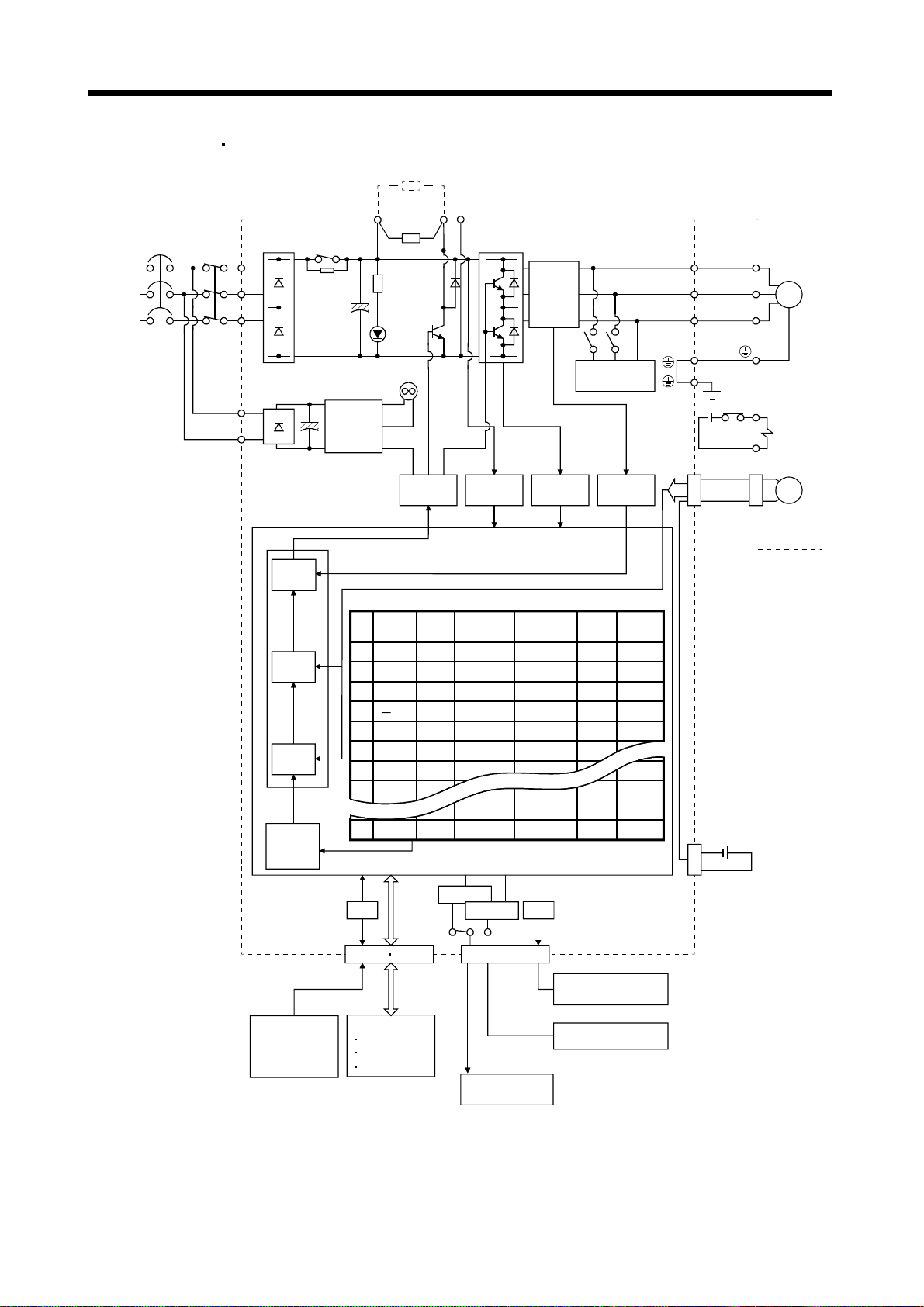
1.1.1 Function block diagram
The function block diagram of this servo is shown below.
1 - 1
Page 21

(
)
y
1. FUNCTIONS AND CONFIGURATION
(1) MR-J2S-350CP or less
Regenerative option
Note 2
Power
suppl
NFB
MC
Servo amplifier
L
1
Diode
stack
Relay
L2
L3
L
11
L21
Current
control
Speed
control
Model adaptive control
Position
control
Position
command
creation
PDC
Regenerative
transistor
CHARGE
lamp
(Note 3) Cooling fan
Control
power
supply
amplifier
Position
No.
data
1
1000
2
2000
3
4000
4
500
5
1000
6
2000
7
1000
8
1000
31
2000
A/D
CN1A CN1B
(Note 1)
Base
Acceleration
time
Speed
constant
1000 80
2000
2000
2000
2000
1000
1000
1000
1000
2000
RS-232C
I/F
Voltage
detection
Point table
100
70
60
80
80
80
100
100
80
RS-422
CN3
Current
detector
Overcurrent
protection
Deceleration
time
constant
80
100
60
70
80
80
80
100
100
80
D/A
Dynamic
brake
Current
detection
Dwell
0
0
500
1000
0
0
0
0
0
Auxiliary
0
0
1
1
0
0
0
0
0
0
Servo motor
U
U
V
V
M
W
W
B1
Electromagnetic
B2
brake
CN2
Encoder
MR-BAT
CON1
Optional battery
(for absolute position
detection system)
Analog monitor
(2 channels)
Controller
RS-422/RS-232C
Analog
(2 channels)
D I/O control
Servo on
Start
Failure, etc.
To other servo
amplifier
Note 1. The built-in regenerative resistor is not provided for the MR-J2S-10CP (1).
2. For 1-phase 230VAC, connect the power supply to L
specification. L
3. Servo amplifiers MR-J2S-200CP have a cooling fan.
is not provided for a 1-phase 100 to120VAC power supply.
3
, L2 and leave L3 open. Refer to section 1.2 for the power supply
1
1 - 2
Page 22
r
1. FUNCTIONS AND CONFIGURATION
(2) MR-J2S-500CP
700CP
Regenerative option
(Note)
Power
supply
NFB
MC
Servo amplifier
L
L
Diode
1
2
stack
Relay
L3
L11
L
21
Current
control
Speed
control
Model adaptive control
Position
control
Position
command
creation
PNC
CHARGE
Cooling fan
Control
power
supply
Position
No.
data
1
1000
2
2000
3
4000
4
5
1000
6
2000
7
1000
8
1000
31
2000
A/D
CN1A CN1B
Regenerative
transistor
lamp
Base
amplifier
Speed
1000 80
2000
2000
500
2000
2000
1000
1000
1000
1000
2000
I/F
Voltage
detection
Acceleration
time
constant
100
100
100
RS-232C
RS-422
Point table
70
60
80
80
80
80
CN3
Current
detector
Overcurrent
protection
Deceleration
time
constant
80
100
60
70
80
80
80
100
100
80
D/A
Dynamic
brake
Current
detection
Dwell
0
0
500
1000
0
0
0
0
0
Auxiliary
0
0
1
1
0
0
0
0
0
0
Servo moto
U
U
V
V
M
W
W
B1
Electromagnetic
B2
brake
CN2
Encoder
MR-BAT
CON1
Optional battery
(for absolute position
detection system)
Analog
(2 channels)
Servo on
Start
Failure, etc.
Note. Refer to section 1.2 for the power supply specification.
D I/O control
To other servo
amplifier
1 - 3
Analog monitor
(2 channels)
Controller
RS-422/RS-232C
Page 23

1. FUNCTIONS AND CONFIGURATION
1.1.2 System configuration
This section describes operations using this servo.
You can arrange any configurations from a single-axis to max. 32-axis systems. Further, the connector
pins in the interface section allow you to assign the optimum signals to respective systems. (Refer to
sections 1.1.3 and 3.3.2.) The MR Configurator (servo configuration software) (refer to chapter 6) and
personal computer are required to change or assign devices.
Set the following values to the point table.
Name Setting range Unit
0.001[mm]
Position data 999999 to 999999
Servo motor speed 0 to max. speed [r/min]
Acceleration time constant 0 to 20000 [ms]
Deceleration time constant 0 to 20000 [ms]
Dwell 0 to 20000 [ms]
Auxiliary function
(Refer to section 4.2)
0 to 3
0.01[mm]
0.1[mm]
1[mm]
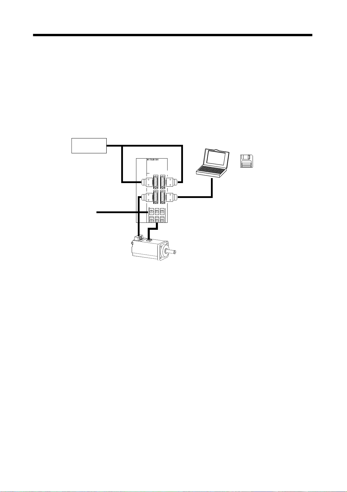
(1) Operation using external input signals
(a) Description
The following configuration example assumes that external input signals are used to control all
signals (devices).
The I/O signals are as factory-set.
(b) Configuration
The following configuration uses external I/O signals. The personal computer is used with MR
Configurator (servo configuration software) to set, change and monitor the parameters and point
tables.
External I/O
signals
Personal
computer
Servo amplifier
MR Configurator
(Servo configuration
Software)
CN1A CN1B
CN2 CN3
Power supply
RS–232C
Servo motor
1 - 4
Page 24
1. FUNCTIONS AND CONFIGURATION
(2) Operation using external input signals and communication
(a) Description
Communication can be used to change the point table data, choose the point table, change
parameter values, and confirm monitor data, for example. Enter a forward rotation start (ST1) or
reverse rotation start (ST2) through the external I/O. Use this system when position data/speed
setting or the host personal computer or the like is used to change the parameter values, for
example.
(b) Configuration
1) One servo amplifier is connected with the personal computer by RS-232C.
External I/O
signals
Servo amplifier
Personal
computer
MR Configurator
(Servo configuration
Software)
CN1A CN1B
CN2 CN3
Power supply
RS–232C
Servo motor
1 - 5
Page 25
1. FUNCTIONS AND CONFIGURATION
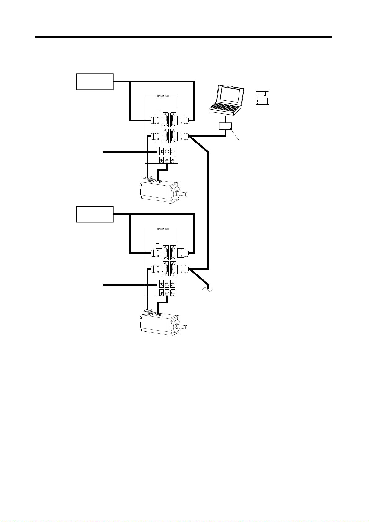
2) Several (up to 32) servo amplifiers are connected with the personal computer by RS-422.
Use parameter No. 16 to change the communication system.
External I/O
signals
Servo amplifier (axis 1)
Personal
computer
MR Configurator
(Servo configuration
Software)
Power supply
External I/O
signals
Power supply
CN1A CN1B
CN2 CN3
Servo amplifier (axis 2)
CN1A CN1B
CN2 CN3
Servo motor
RS–232C
RS–422
RS–232C/RS-422 converter
(to be prepared by the customer)
RS–422
To the next axis
Servo motor
1 - 6
Page 26
1. FUNCTIONS AND CONFIGURATION
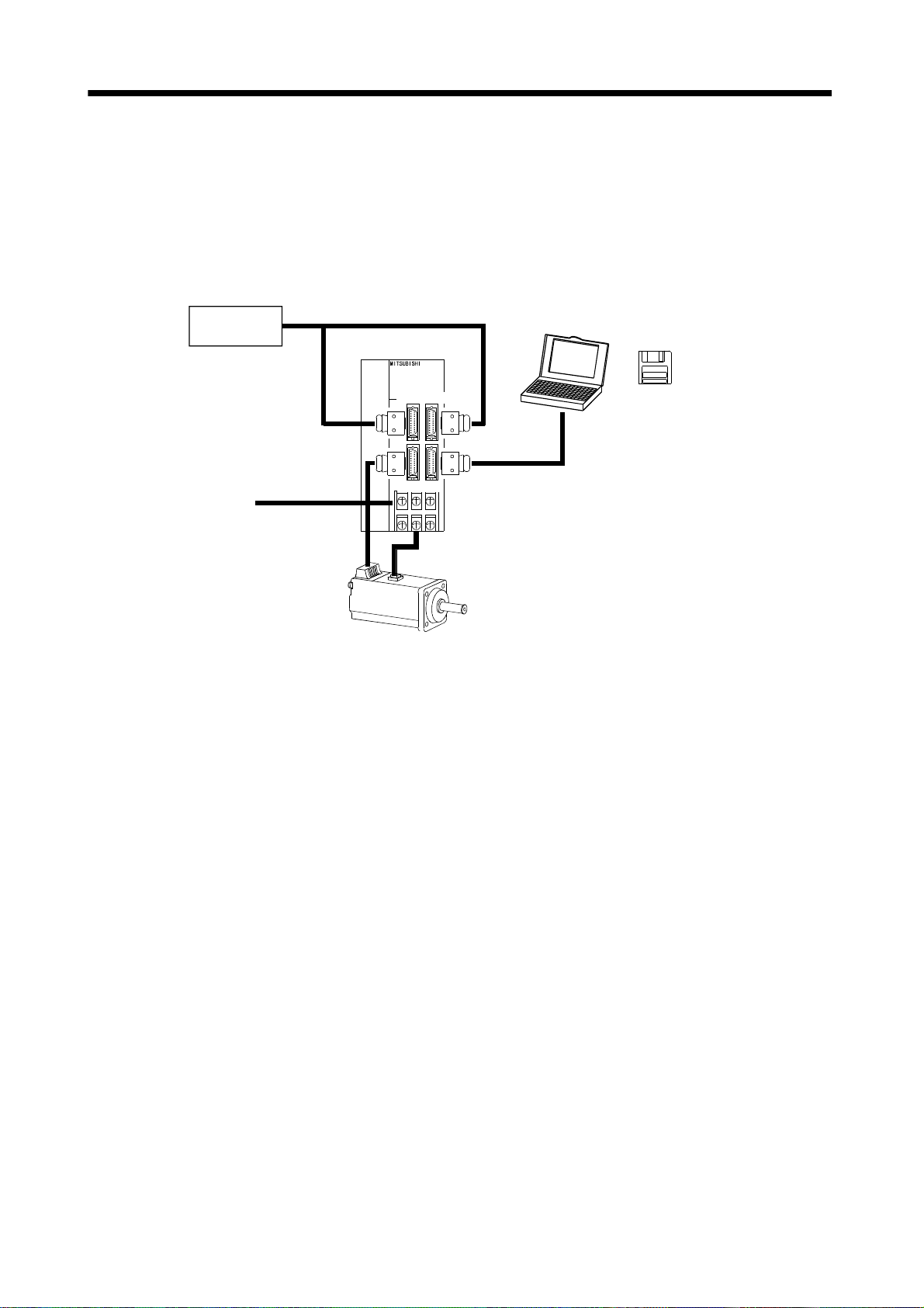
(3) Operation using communication
(a) Description
Analog input, forced stop (EMG) and other signals are controlled by external I/O signals and the
other devices controlled through communication. Also, you can set each point table, choose the
point table, and change or set parameter values, for example. Up to 32 axes may be controlled.
(b) Configuration
1) One servo amplifier is connected with the personal computer by RS-232C.
External I/O
signals
Servo amplifier
Personal
computer
MR Configurator
(Servo configuration
Software)
CN1A CN1B
CN2 CN3
Power supply
RS–232C
Servo motor
1 - 7
Page 27

1. FUNCTIONS AND CONFIGURATION
2) Several (up to 32) servo amplifiers are connected with the personal computer by RS-422.
Use parameter No. 16 to change the communication system.
External I/O
signals
Servo amplifier (axis 1)
Personal
computer
MR Configurator
(Servo configuration
Software)
Power supply
External I/O
signals
Power supply
CN1A CN1B
CN2 CN3
Servo amplifier (axis 2)
CN1A CN1B
CN2 CN3
Servo motor
RS–232C
RS–422
RS–232C/RS-422 converter
(to be prepared by the customer)
RS–422
To the next axis
Servo motor
1 - 8
Page 28
1. FUNCTIONS AND CONFIGURATION
1.1.3 I/O devices
This servo amplifier allows devices to be allocated to the pins of connector CN1A/CN1B as desired. The
following devices can be allocated. For device details, refer to section 3.3.2.
Input device Symbol
Proximity dog DOG CN1A-8 Home position return completion ZP CN1A-18
Servo-on SON CN1B-15 Rough match CPO CN1B-4
Forward rotation stroke end LSP CN1B-16 Movement finish MEND CN1B-6
Reverse rotation stroke end LSN CN1B-17 Trouble ALM CN1B-18
Forward rotation start ST1 CN1B-8 Ready RD CN1B-19
Reverse rotation start ST2 CN1B-9 Electromagnetic brake interlock MBR
Automatic/manual selection MD0 CN1B-7 Position range output POT
Point table No. selection 1 DI0 CN1B-5 Warning output WNG
Point table No. selection 2 DI1 CN1B-14 Battery warning output BWNG
Point table No. selection 3 DI2 Limiting torque TLC
Point table No. selection 4 DI3 Temporary stop PUS
Point table No. selection 5 DI4 In position INP
Forced stop EMG Point No. output 1 PT0
Reset RES Point No. output 2 PT1
Override selection OVR Point No. output 3 PT2
External torque limit selection TL Point No. output 4 PT3
Internal torque limit selection TL2 Point No. output 5 PT4
Proportion control PC
Temporary stop/restart STP
Manual pulse generator
multiplication 1
Manual pulse generator
multiplication 2
Gain switch CDP
Teach TCH
TP0
TP1
Factory-
allocated pin
Output device Symbol
Factory-
allocated pin
1 - 9
Page 29
1. FUNCTIONS AND CONFIGURATION
1.2 Servo amplifier standard specifications
Servo amplifier
Item
Voltage/frequency
Permissible voltage fluctuation
Permissible frequency fluctuation Within 5%
Power supply
Power supply capacity Refer to section13.2
Inrush current Refer to section13.5
Control system Sine-wave PWM control, current control system
Dynamic brake Built-in
Protective functions
Operational
specifications
Position command
input
Speed command
input
System
Operational
specifications
Position command
input
Speed command
input
System
Point table
Automatic continuous
operation
Jog
Manual pulse
generator
Dog type
Count type
Data setting type
Stopper type
Command system
Operation mode
Point table
number
input
Position
data input
Automatic
operation
mode
Manual
operation
mode
Manual
home
position
return
mode
MR-J2S-
10CP 20CP 40CP 60CP 70CP 100CP 200CP 350CP 500CP 700CP 10CP1 20CP1 40CP1
3-phase 200 to 230VAC, 50/60Hz
or 1-phase 230VAC, 50/60Hz
3-phase 200 to 230VAC:
170 to 253VAC
1-phase 230VAC: 207 to 253VAC
Overcurrent shut-off, regenerative overvoltage shut-off, overload shut-off (electronic
thermal relay), servo motor overheat protection, encoder error protection, regenerative
brake error protection, undervoltage, instantaneous power failure protection, overspeed
protection, excessive error protection
Positioning by specifying the point table No. (31 points)
Set in point table. 1-point feed length setting range: 1[ m] to 999.999[mm]
Set in point table. Acceleration/deceleration time is set in point table.
S-pattern acceleration/deceleration time constant is set in parameter No.14.
Signed absolute value command system, incremental value command system, signed
absolute value command/incremental value command specifying system
Positioning using RS-422 (232C) communication data
Setting through RS-422 (232C) communication
1-point feed length setting range:
Setting through RS-422 (232C) communication
Acceleration/deceleration time is also set through RS-422 (232C) communication.
S-pattern acceleration/deceleration time constant is set in parameter No.14.
Signed absolute value command system, incremental value command system, signed
absolute value command/incremental value command specifying system
Point table number input, position data input system
Positioning operation is performed once in accordance with the position and speed
commands.
Varied speed operation (2 to 31 speeds), automatic continuous positioning operation (2 to
31 points)
Jog operation is performed in accordance with the parameter-set speed command by
contact input or through RS-422 (232C) communication.
Manual feed is made by manual pulse generator.
Command pulse multiplication:
Home position return is made starting with Z-phase pulse after passage of proximity dog.
Home position address may be set. Home position shift distance may be set. Home position
return direction may be selected.
Automatic at-dog home position return return/automatic stroke return function
Home position return is made by counting encoder pulses after contact with proximity dog.
Home position address may be set. Home position shift value may be set. Home position
return direction may be set.
Automatic at-dog home position return return/automatic stroke return function
Home position return is made without dog.
Home position may be set at any position by manual operation, etc. Home position address
may be set.
Home position return is made by pressing machine part against stroke end.
Home position address may be set. Home position return direction may be set.
3-phase 200 to 230VAC, 50/60Hz
3-phase 170 to 253VAC
1[ m] to 999.999[mm]
1, 10 or 100 is selected using parameter.
1-phase 100 to
120VAC 50/60Hz
1-phase
85 to 127VAC
1 - 10
Page 30

1. FUNCTIONS AND CONFIGURATION
Servo amplifier
MR-J2S-
Item
Home position
ignorance
(Servo-on position as
home position)
Manual
home
position
return
mode
Operation mode
Automatic positioning to home
position
Other functions
Structure Self-cooled, open (IP00) Force-cooling, open (IP00)
Ambient
temperature
humidity
Ambient
Environment
Altitude Max. 1000m (3280ft) above sea level
Vibration
Mass
Dog type rear end
reference
Count type front end
reference
Dog cradle type
In Operation
In storage
In Operation Ambient
In storage
10CP 20CP 40CP 60CP 70CP 100CP 200CP 350CP 500CP 700CP 10CP1 20CP1 40CP1
Position where servo-on (SON) is switched on is defined as home position.
Home position address may be set.
Home position return is made with respect to the rear end of a proximity dog.
Home position address may be set. Home position shift value may be set. Home position
return direction may be set.
Automatic at-dog home position return return/automatic stroke return function
Home position return is made with respect to the front end of a proximity dog.
Home position address may be set. Home position shift value may be set. Home position
return direction may be set.
Automatic at-dog home position return return/automatic stroke return function
Home position return is made with respect to the front end of a proximity dog by the first
Z-phase pulse.
Home position address may be set. Home position shift value may be set. Home position
return direction may be set.
Automatic at-dog home position return return/automatic stroke return function
High-speed automatic return to a defined home position.
Absolute position detection, backlash function
Overtravel prevention using external limit switch
Software stroke limit, override using external analog signal
Amplifier front button-operated teaching function/external teaching pendant input
signal interface
[ ] 0 to 55 (non-freezing)
[
] 32 to 131 (non-freezing)
[ ] 20 to 65 (non-freezing)
[
] 4 to 149 (non-freezing)
90%RH or less (non-condensing)
Indoors (no direct sunlight)
Free from corrosive gas, flammable gas, oil mist, dust and dirt
5.9 [m/s2] or less
19.4 [ft/s
[kg] 0.7 0.7 1.1 1.1 1.7 1.7 2.0 2.0 4.9 7.2 0.7 0.7 1.1
[lb]
2
] or less
1.5 1.5 2.4 2.4 3.75 3.75 4.4 4.4 10.8 15.87 1.5 1.5 2.4
Self-cooled,
open (IP00)
1 - 11
Page 31

1. FUNCTIONS AND CONFIGURATION
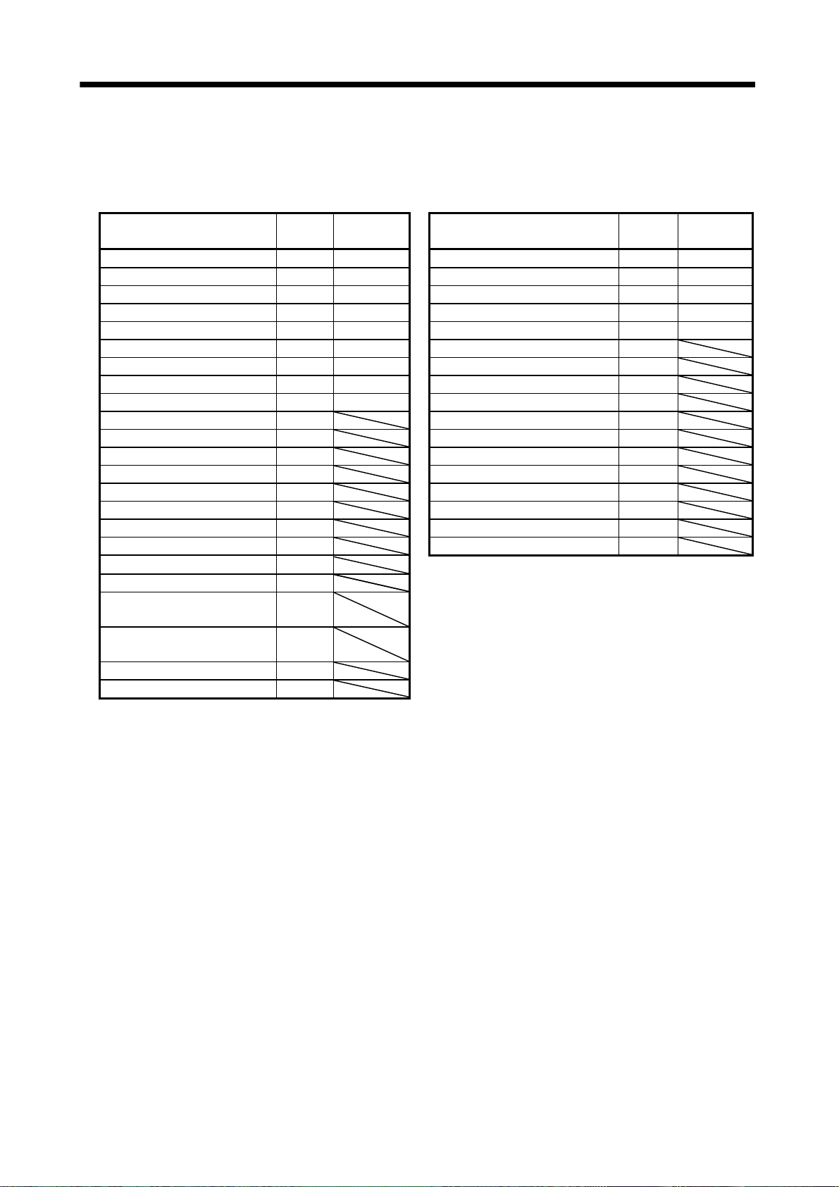
1.3 Function list
The following table lists the functions of this servo. For details of the functions, refer to the reference field.
Function Description Reference
Select the required ones from among 31 preset point tables and
Positioning by automatic operation
Varied speed operation
Automatic continuous positioning
operation
Manual home position return
Multidrop communication
High-resolution encoder
Absolute position detection system
Gain changing function
Adaptive vibration suppression control
Low-pass filter
Machine analyzer function
Machine simulation
Gain search function
Slight vibration suppression control Vibration of 1 pulse at servo motor stop is suppressed. Parameter No. 20
Electronic gear
Auto tuning
S-pattern acceleration/deceleration time
constant
Regenerative option
Brake unit
Return converter
perform operation in accordance with the set values.
Use the external input signal or communication function to choose
the point tables.
Servo motor speed can be varied continuously until the preset
moving distance is reached. (Max. set speeds: 31 speeds)
By merely choosing one point table and starting operation,
positioning can be executed continuously in accordance with
several point tables.
Dog type, count type, data setting type, stopper type, home
position ignorance, dog type rear end reference, count type front
end reference, dog cradle type
Up to 32 axes of MR-J2S-CP are controllable simultaneously by
RS-422 communication.
High-resolution encoder of 131072 pulses/rev is used as a servo
motor encoder.
By merely setting the home position once, home position return
need not be done at each power on.
You can switch between gains during rotation and gains during
stop or use an external signal to change gains during operation.
Servo amplifier detects mechanical resonance and sets filter
characteristics automatically to suppress mechanical vibration.
Suppresses high-frequency resonance which occurs as servo
system response is increased.
Analyzes the frequency characteristic of the mechanical system by
simply connecting a MR Configurator (servo configuration
software)-installed personal computer and servo amplifier.
Can simulate machine motions on a personal computer screen on
the basis of the machine analyzer results.
Personal computer changes gains automatically and searches for
overshoot-free gains in a short time.
The electronic gear is used to make adjustment so that the servo
amplifier setting matches the machine moving distance. Also,
changing the electronic gear value allows the machine to be moved
at any multiplication ratio to the moving distance using the servo
amplifier.
Automatically adjusts the gain to optimum value if load applied to
the servo motor shaft varies. Higher in performance than MR-J2
series servo amplifier.
Acceleration/deceleration can be made smoothly. Section 5.2.3
Used when the built-in regenerative resistor of the servo amplifier
does not have sufficient regenerative capability for the
regenerative power generated.
Used when the regenerative option cannot provide enough
regenerative power.
Can be used with the MR-J2S-500CP
Used when the regenerative option cannot provide enough
regenerative power.
Can be used with the MR-J2S-500CP
MR-J2S-700CP.
MR-J2S-700CP.
Section 4.2
Section 4.2.6 (2)
Section 4.2.6 (1)
Section 4.4
Section 4.6.3
Chapter 15
Section 4.5
Section 9.5
Section 9.3
Section 9.4
Section 5.2.1
Chapter 8
Section 14.1.1
Section 14.1.2
Section 14.1.3
1 - 12
Page 32

1. FUNCTIONS AND CONFIGURATION
Function Description Reference
Analog monitor The servo status is output in terms of voltage in real time. Section 5.2.4
By using the MR Configurator (servo configuration software), the
Alarm history
I/O signal selection (Device setting)
Torque limit
Override (speed limit)
Status display The servo status is displayed. Section 7.2
Test operation mode
Limit switch
Software limit
current alarm and five past alarm numbers are stored and
displayed.
By using the MR Configurator (servo configuration software), any
devices can be assigned to 9 input, 5 output and 1 I/O pins.
Servo motor-torque is limited.
Parameter 2 limit value
Analog input
The servo motor speed is limited by analog input.
The ratio of override to the set speed can be changed between 0 to
200%.
Jog operation, positioning operation, motor-less operation, DO
forced output, 1-step feed
The servo motor travel region can be limited using the forward
rotation stroke end (LSP)/reverse rotation stroke end (LSN).
The travel region is limited using parameters in terms of address.
The function similar to that of a limit switch is limited by
parameter.
1 limit value
Section 6.8
Section 6.6
Section 3.4.4
Section 3.4.3
Section 6.7
Section 5.2.5
Section 5.2.8
1.4 Model code definition
(1) Rating plate
MITSUBISHI
MODEL
POWER
MR-J2S-60CP
POWER :
INPUT :
OUTPUT :
SERIAL :
MITSUBISHI ELECTRIC CORPORATION
MADE IN JAPAN
AC SERVO
AC SERVO
600W
3.2A 3PH 1PH200-230V 50Hz
3PH 1PH200-230V 60Hz
5.5A 1PH 230V 50/60Hz
170V 0-360Hz 3.6A
A5
TC3 AAAAG52
PASSED
Model
Capacity
Applicable power supply
Rated output current
Serial number
1 - 13
Page 33

1. FUNCTIONS AND CONFIGURATION
(2) Model
MR–J2S–
CP
MR–J2S–100CP or less
MR–J2S–200CP 350CP
Series
Symbol
None
(Note 2)
1
Note 1. 1-phase 230V is supported
by 750W or less.
2. 1-phase 100V to 120V is
supported by 400W or less.
Rated output
Symbol
10
20
40
60
70
Power Supply
Power supply
3-phase 200 to 230VAC
(Note 1) 1-phase 230VAC
1-phase 100V to 120VAC
Built-in positioning functions
Rated
output [W]
100
200
400
600
750
Symbol
Rated
output [W]
1000100
2000200
3500350
5000500
7000700
Rating plate
MR-J2S-500CP
Rating plate
MR-J2S-700CP
Rating plate
Rating plate
1.5 Combination with servo motor
The following table lists combinations of servo amplifiers and servo motors. The same combinations apply
to the models with electromagnetic brakes and the models with reduction gears.
Servo motors
Servo amplifier
MR-J2S-10CP(1) 053 13 053 13 13
MR-J2S-20CP (1) 23 23 23
MR-J2S-40CP (1) 43 43 43
MR-J2S-60CP 52 53
MR-J2S-70CP 73 73 72 73
MR-J2S-100CP 81 102 103
MR-J2S-200CP 121 201 152 202 153 203 103 153 152
MR-J2S-350CP 301 352 353 203 202
MR-J2S-500CP 502 353 503 352 502
MR-J2S-700CP 702
HC-KFS
HC-MFS
1000r/min 2000r/min 3000r/min
HC-SFS HC-UFS
HC-RFS
2000r/min 3000r/min
Servo motors
Servo amplifier
1000r/min 1500r/min 2000r/min
MR-J2S-60CP 52
MR-J2S-100CP 102
MR-J2S-200CP 152
MR-J2S-350CP 202
MR-J2S-500CP 502 302
MR-J2S-700CP (Note 2)601 (Note 2)701M 702
Note 1. These servo motors may not be connected depending on the production time of the servo amplifier. Please refer to Appendix 3.
2. Consult us since the servo amplifier to be used with any of these servo motors is optional.
HA-LFS
(Note 1)
HC-LFS
1 - 14
Page 34

1. FUNCTIONS AND CONFIGURATION
1.6 Structure
1.6.1 Part names
(1) MR-J2S-100CP or less
MODE
UP DOWN
Name/Application
Battery holder
Contains the battery for absolute position data backup.
Battery connector (CON1)
Used to connect the battery for absolute position data
backup.
Display
The 5-digit, seven-segment LED shows the servo
status and alarm number.
Operation section
Used to perform status display, diagnostic, alarm,
parameter and point table setting operations.
SET
MODE
I/O signal connector (CN1A)
Used to connect digital I/O signals.
UP DOWN
SET
Used to set data.
Used to change the
display or data in each
mode.
Used to change the
mode.
Reference
Section4.5
Section4.5
Chapter7
Chapter7
Section3.3
I/O signal connector (CN1B)
Used to connect digital I/O signals.
Communication connector (CN3)
Used to connect a command device (RS-422/RS-232C)
and output analog monitor data.
Name plate
Charge lamp
Lit to indicate that the main circuit is charged. While
this lamp is lit, do not reconnect the cables.
Encoder connector (CN2)
Used to connect the servo motor encoder.
Main circuit terminal block (TE1)
Used to connect the input power supply and servo
motor.
Control circuit terminal block (TE2)
Used to connect the control circuit power supply and
regenerative option.
Protective earth (PE) terminal ( )
Ground terminal.
Fixed part (2 places)
(For MR-J2S-70CP 100CP 3 places)
Section3.3
Chapter6
Chapter15
Section14.1.4
Section1.4
Section3.3
Section14.1.4
Section3.7.2
Section12.1
Section3.7.2
Section12.1
Section14.1.1
Section3.10
1 - 15
Page 35

1. FUNCTIONS AND CONFIGURATION
(2) MR-J2S-200CP
MR-J2S-350CP
POINT
This servo amplifier is shown without the front cover. For removal of the
front cover, refer to section 1.6.2.
Name/Application
Reference
MODE UP DOWN
Battery holder
Contains the battery for absolute position data backup.
Battery connector (CON1)
Used to connect the battery for absolute position data
backup.
Display
The 5-digit, seven-segment LED shows the servo
status and alarm number.
Operation section
SET
Used to perform status display, diagnostic, alarm,
parameter and point table setting operations.
DOWN
MODE
I/O signal connector (CN1A)
Used to connect digital I/O signals.
UP
SET
Used to set data.
Used to change the
display or data in each
mode.
Used to change the
mode.
Section4.5
Section4.5
Chapter7
Chapter7
Section3.3
Fixed part (4 places)
Cooling fan
I/O signal connector (CN1B)
Used to connect digital I/O signals.
Communication connector (CN3)
Used to connect a command device (RS-422/RS-232C)
and output analog monitor data.
Name plate
Charge lamp
Lit to indicate that the main circuit is charged. While
this lamp is lit, do not reconnect the cables.
Encoder connector (CN2)
Used to connect the servo motor encoder.
Main circuit terminal block (TE1)
Used to connect the input power supply and servo
motor.
Control circuit terminal block (TE2)
Used to connect the control circuit power supply and
regenerative option.
Protective earth (PE) terminal ( )
Ground terminal.
Section3.3
Chapter6
Chapter15
Section14.1.4
Section1.4
Section3.3
Section14.1.4
Section3.7.2
Section12.1
Section3.7.2
Section12.1
Section14.1.1
Section3.10
1 - 16
Page 36

1. FUNCTIONS AND CONFIGURATION
(3) MR-J2S-500CP
POINT
The servo amplifier is shown without the front cover. For removal of the
front cover, refer to section 1.6.2.
Battery connector (CON1)
Used to connect the battery for absolute position data
backup.
Battery holder
Contains the battery for absolute position data backup.
Display
The 5-digit, seven-segment LED shows the servo
status and alarm number.
Operation section
MODE
UP DOWN SET
Used to perform status display, diagnostic, alarm,
parameter and point table setting operations.
Name/Application Reference
Section4.5
Section4.5
Chapter7
Fixed part
(4 places)
MODE
I/O signal connector (CN1A)
Used to connect digital I/O signals.
I/O signal connector (CN1B)
Used to connect digital I/O signals.
Communication connector (CN3)
Used to connect a command device (RS-422/RS-232C)
and output analog monitor data.
Encoder connector (CN2)
Used to connect the servo motor encoder.
Charge lamp
Lit to indicate that the main circuit is charged.
While this lamp is lit, do not reconnect the cables.
Control circuit terminal block (TE2)
Used to connect the control circuit power supply and
regenerative option.
UP
DOWN SET
Used to set data.
Used to change the
display or data in each
mode.
Used to change the
mode.
Chapter7
Section3.3
Section3.3
Chapter6
Chapter15
Section14.1.4
Section3.3
Section14.1.4
Section3.7.2
Section12.1
Main circuit terminal block (TE1)
Used to connect the input power supply and servo
motor.
Name plate Section1.4
Cooling fan
Protective earth (PE) terminal ( )
Ground terminal.
Section3.7.2
Section12.1
Section14.1.1
Section3.10
1 - 17
Page 37

1. FUNCTIONS AND CONFIGURATION
(4) MR-J2S-700CP
POINT
The servo amplifier is shown without the front cover. For removal of the
front cover, refer to next page.
Battery connector (CON1)
Used to connect the battery for absolute position data
backup.
Battery holder
Contains the battery for absolute position data backup.
Display
The 5-digit, seven-segment LED shows the servo
status and alarm number.
Operation section
MODE
UP DOWN
SET
Used to perform status display, diagnostic, alarm,
parameter and point table setting operations.
Name/Application
Reference
Section4.5
Section4.5
Chapter7
MODE UP DOWN SET
Used to set data.
Used to change the
display or data in each
mode.
Used to change the
mode.
I/O signal connector (CN1A)
Used to connect digital I/O signals.
I/O signal connector (CN1B)
Used to connect digital I/O signals.
Communication connector (CN3)
Used to connect a command device (RS-422/RS-232C)
and output analog monitor data.
Charge lamp
Lit to indicate that the main circuit is charged.
While this lamp is lit, do not reconnect the cables.
Control circuit terminal block (TE2)
Used to connect the control circuit power supply.
Chapter7
Section3.3
Section3.3
Chapter6
Chapter15
Section14.1.4
Section3.7.2
Section12.1
Cooling fan
Fixed part
(4 places)
Encoder connector (CN2)
Used to connect the servo motor encoder.
Name plate
Main circuit terminal block (TE1)
Used to connect the input power supply, regenerative
option and servo motor.
Protective earth (PE) terminal ( )
Ground terminal.
1 - 18
Section3.3
Section14.1.4
Section1.4
Section3.7.2
Section12.1
Section14.1.1
Section3.10
Page 38
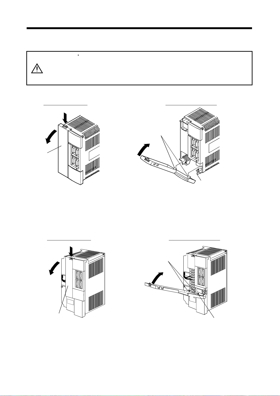
r
1. FUNCTIONS AND CONFIGURATION
1.6.2 Removal and reinstallation of the front cover
Before removing or installing the front cover, turn off the power and wait for 15
minutes or more until the charge lamp turns off. Then, confirm that the voltage
WARNING
between P and N is safe with a voltage tester and others. Otherwise, an electric
shock may occur. In addition, always confirm from the front of the servo amplifier
whether the charge lamp is off or not.
(1) For MR-J2S-200CP or more
Removal of the front cover
1)
Reinstallation of the front cover
2)
Front cove
1) Hold down the removing knob.
2) Pull the front cover toward you.
(2) For MR-J2S-500CP
Removal of the front cover
1)
2)
Front cover hook
(2 places)
2)
1)
Front cover socket
(2 places)
1) Insert the front cover hooks into the front cover sockets of
the servo amplifier.
2) Press the front cover against the servo amplifier until the
removing knob clicks.
Reinstallation of the front cover
Front cover hook
(2 places)
2)
1)
Front cover
Front cover socket
(2 places)
1) Hold down the removing knob.
2) Pull the front cover toward you.
1) Insert the front cover hooks into the front cover sockets of
the servo amplifier.
2) Press the front cover against the servo amplifier until the
removing knob clicks.
1 - 19
Page 39

r
r
1. FUNCTIONS AND CONFIGURATION
(3) For MR-J2S-700CP
Removal of the front cove
Reinstallation of the front cove
Front cover
hook
(2 places)
B)
2)
1)
A)
1) Push the removing knob A) or B), and put you
finger into the front hole of the front cover.
2) Pull the front cover toward you.
A)
2)
1)
Front cover socket
(2 places)
1) Insert the two front cover hooks at the bottom into the
sockets of the servo amplifier.
2) Press the front cover against the servo amplifier until the
removing knob clicks.
1 - 20
Page 40

1. FUNCTIONS AND CONFIGURATION
1.7 Servo system with auxiliary equipment
To prevent an electric shock, always connect the protective earth (PE) terminal
WARNING
(terminal marked
) of the servo amplifier to the protective earth (PE) of the control
box.
(1) MR-J2S-100CP or less
(a) For 3-phase 200V to 230VAC or 1-phase 230VAC
(Note 2)
Power supply
Circuit breaker
(NFB) or fuse
Options and auxiliary equipment
Circuit breaker
Magnetic contactor
MR Configurator
(Servo configuration software)
Regenerative option
Servo amplifier
Reference
Section 14.2.2
Section 14.2.2
Chapter 6
Section 14.1.1
To CN1A
Options and auxiliary equipment
Cables
Manual pulse generator
External digital display
Power factor improving reactor
Command device
Junction terminal block
Reference
Section 14.2.1
Section 14.1.8
Section 14.1.7
Section 14.2.3
Magnetic
contactor
(MC)
Power
factor
improving
reactor
(FR-BAL)
Control circuit terminal block
L
21
To CN2
L
1
L
2
L
3
U
CHARGE
VW
D
To CN1B
To CN3
Protective earth (PE) terminal
Manual pulse generator
External digital display
MR Configurator
Personal
computer
(Note 1)
Encoder cable
(Note 1)
Power supply lead
(Servo configuration
software
MRZJW3-SETUP151E)
L
11
P
Regenerative option
C
Note 1. The HC-SFS, HC-RFS, HC-UFS 2000r/min series have cannon connectors.
2. A 1-phase 230VAC power supply may be used with the servo amplifier of MR-J2S-70CP or less.
For 1-phase 230VAC, connect the power supply to L
specification.
L2 and leave L3 open. Refer to section 1.2 for the power supply
1
Servo motor
1 - 21
Page 41

1. FUNCTIONS AND CONFIGURATION
(b) For 1-phase 100V to 120VAC
(Note 2)
Power supply
Circuit breaker
(NFB) or fuse
Options and auxiliary equipment
Circuit breaker
Magnetic contactor
MR Configurator
(Servo configuration software)
Regenerative option
Servo amplifier
Reference
Section 14.2.2
Section 14.2.2
Chapter 6
Section 14.1.1
To CN1A
Options and auxiliary equipment
Cables
Manual pulse generator
External digital display
Power factor improving reactor
Command device
Junction terminal block
Reference
Section 14.2.1
Section 14.1.8
Section 14.1.7
Section 14.2.3
Magnetic
contactor
(MC)
Power
factor
improving
reactor
(FR-BAL)
Control circuit terminal block
L
21
L
11
To CN2
L1
2
L
CHARGE
UVW
D
To CN1B
External digital display
To CN3
Protective earth (PE) terminal
Manual pulse generator
Personal
computer
(Note 1)
Encoder cable
(Note 1)
Power supply lead
MR Configurator
(Servo configuration
software
MRZJW3-SETUP151E)
P
Regenerative option
C
Note 1. The HC-SFS, HC-RFS, HC-UFS 2000 r/min series have cannon connectors.
2. Refer to section 1.2 for the power supply specification.
1 - 22
Servo motor
Page 42

1. FUNCTIONS AND CONFIGURATION
(2) MR-J2S-200CP
(Note)
Power supply
Circuit
breaker
(NFB) or
fuse
Magnetic
contactor
(MC)
Power
factor
improving
reactor
(FR-BAL)
MR-J2S-350CP
Options and auxiliary equipment
Circuit breaker
Magnetic contactor
MR Configurator
(Servo configuration software)
Regenerative option
To CN2
L
11
L
21
Servo amplifier
Reference
Section 14.2.2
Section 14.2.2
Chapter 6
Section 14.1.1
Options and auxiliary equipment
Cables
Manual pulse generator
External digital display
Power factor improving reactor
Command device
To CN1A
To CN1B
To CN3
External digital display
Personal
computer
Reference
Section 14.2.1
Section 14.1.8
Section 14.1.7
Section 14.2.3
Junction terminal
block
Manual pulse
generator
MR Configurator
(Servo
configuration
software
MRZJW3SETUP151E)
L
1
L
2
L
3
Note. Refer to section 1.2 for the power supply specification.
CUV
P
W
Regenerative option
1 - 23
Page 43

1. FUNCTIONS AND CONFIGURATION
(3) MR-J2S-500CP
(Note 2)
Power supply
Circuit
breaker
(NFB) or
fuse
Magnetic
contactor
(MC)
Power
factor
improving
reactor
(FR-BAL)
(Note 1)
Regenerative option
L11
L
C
P
21
Options and auxiliary equipment
Circuit breaker
Magnetic contactor
MR Configurator
(Servo configuration software)
Regenerative option
Servo amplifier
L1
L
2
L
3
U
V
W
Reference
Section 14.2.2
Section 14.2.2
Chapter 6
Section 14.1.1
To CN1A
To CN1B
To CN3
To CN2
Options and auxiliary equipment
Cables
Manual pulse generator
External digital display
Power factor improving reactor
Command device
Junction terminal
block
Manual pulse
generator
External digital display
Personal
computer
Reference
Section 14.2.1
Section 14.1.8
Section 14.1.7
Section 14.2.3
MR Configurator
(Servo
configuration
software
MRZJW3SETUP151E)
Note 1. When using the regenerative option, remove the lead wires of the built-in regenerative resistor.
2. Refer to section 1.2 for the power supply specification.
1 - 24
Page 44

1. FUNCTIONS AND CONFIGURATION
(4) MR-J2S-700CP
(Note 2)
Power supply
Circuit
breaker
(NFB) or
fuse
Magnetic
contactor
(MC)
Power
factor
improving
reactor
(FR-BAL)
Options and auxiliary equipment
Circuit breaker
Magnetic contactor
MR Configurator
(Servo configuration software)
Regenerative option
Servo amplifier
11
L
L21
L3
L2
L1
Reference
Section 14.2.2
Section 14.2.2
Chapter 6
Section 14.1.1
To CN1A
To CN1B
To CN3
To CN2
U
V
W
Options and auxiliary equipment
Cables
Manual pulse generator
External digital display
Power factor improving reactor
Command device
Junction terminal
block
Manual pulse
generator
External digital display
Personal
computer
Reference
Section 14.2.1
Section 14.1.8
Section 14.1.7
Section 14.2.3
MR Configurator
(Servo
configuration
software
MRZJW3SETUP151E)
C
(Note 1)
Regenerative option
Note 1. When using the regenerative option, remove the lead wires of the built-in regenerative resistor.
2. Refer to section 1.2 for the power supply specification.
P
1 - 25
Page 45

1. FUNCTIONS AND CONFIGURATION
MEMO
1 - 26
Page 46

2. INSTALLATION
2. INSTALLATION
Stacking in excess of the limited number of products is not allowed.
Install the equipment on incombustible material. Installing them directly or close to
combustibles will lead to a fire.
Install the equipment in a load-bearing place in accordance with this Instruction
Manual.
Do not get on or put heavy load on the equipment to prevent injury.
Use the equipment within the specified environmental condition range. (For the
environmental conditions, refer to section 2.1.)
Provide an adequate protection to prevent screws, metallic detritus and other
CAUTION
2.1 Environmental conditions
conductive matter or oil and other combustible matter from entering the servo
amplifier.
Do not block the intake/exhaust ports of the servo amplifier. Otherwise, a fault may
occur.
Do not subject the servo amplifier to drop impact or shock loads as they are
precision equipment.
Do not install or operate a faulty servo amplifier.
When the product has been stored for an extended period of time, consult
Mitsubishi.
When treating the servo amplifier, be careful about the edged parts such as the
corners of the servo amplifier.
Environment Conditions
[ ] 0 to 55 (non-freezing) In
Ambient
temperature
Ambient
humidity
Ambience
Altitude Max. 1000m (3280 ft) above sea level
Vibration
operation
In storage
In operation
In storage
[ ] 32 to 131 (non-freezing)
[ ] 20 to 65 (non-freezing)
] 4 to 149 (non-freezing)
[
90%RH or less (non-condensing)
Indoors (no direct sunlight)
Free from corrosive gas, flammable gas, oil mist, dust and dirt
[m/s2] 5.9 [m/s2] or less
2
] 19.4 [ft/s2] or less
[ft/s
2 - 1
Page 47

2. INSTALLATION
2.2 Installation direction and clearances
Do not hold the front cover to transport the servo amplifier. The servo amplifier
may drop.
The equipment must be installed in the specified direction. Otherwise, a fault may
CAUTION
occur.
Leave specified clearances between the servo amplifier and control box inside
walls or other equipment.
(1) Installation of one servo amplifier
Control box Control box
40mm
(1.6 in.)
or more
Servo amplifier
10mm
(0.4 in.)
or more
10mm
(0.4 in.)
or more
Wiring clearance
70mm
(2.8 in.)
Up
Down
40mm
(1.6 in.)
or more
2 - 2
Page 48

2. INSTALLATION
(2) Installation of two or more servo amplifiers
Leave a large clearance between the top of the servo amplifier and the internal surface of the control
box, and install a cooling fan to prevent the internal temperature of the control box from exceeding the
environmental conditions.
Control box
100mm
(4.0 in.)
or more
30mm
(1.2 in.)
or more
40mm
(1.6 in.)
or more
10mm
(0.4 in.)
or more
30mm
(1.2 in.)
or more
(3) Others
When using heat generating equipment such as the regenerative option, install them with full
consideration of heat generation so that the servo amplifier is not affected.
Install the servo amplifier on a perpendicular wall in the correct vertical direction.
2.3 Keep out foreign materials
(1) When installing the unit in a control box, prevent drill chips and wire fragments from entering the
servo amplifier.
(2) Prevent oil, water, metallic dust, etc. from entering the servo amplifier through openings in the control
box or a cooling fan installed on the ceiling.
(3) When installing the control box in a place where there are much toxic gas, dirt and dust, conduct an
air purge (force clean air into the control box from outside to make the internal pressure higher than
the external pressure) to prevent such materials from entering the control box.
2 - 3
Page 49

2. INSTALLATION
2.4 Cable stress
(1) The way of clamping the cable must be fully examined so that flexing stress and cable's own weight
stress are not applied to the cable connection.
(2) For use in any application where the servo motor moves, fix the cables (encoder, power supply, brake)
supplied with the servo motor, and flex the optional encoder cable or the power supply and brake
wiring cables. Use the optional encoder cable within the flexing life range. Use the power supply and
brake wiring cables within the flexing life of the cables.
(3) Avoid any probability that the cable sheath might be cut by sharp chips, rubbed by a machine corner
or stamped by workers or vehicles.
(4) The flexing lives of the cables are shown below. In actuality, provide a little allowance for these values.
For installation on a machine where the servo motor will move, the flexing radius should be made as
large as possible. Refer to section 13.4 for the flexing life.
2 - 4
Page 50

3. SIGNALS AND WIRING
3. SIGNALS AND WIRING
Any person who is involved in wiring should be fully competent to do the work.
Before wiring, turn off the power and wait for 15 minutes or more until the charge
lamp turns off. Then, confirm that the voltage between P and N is safe with a
voltage tester and others. Otherwise, an electric shock may occur. In addition,
always confirm from the front of the servo amplifier whether the charge lamp is off
WARNING
or not.
Ground the servo amplifier and the servo motor securely.
Do not attempt to wire the servo amplifier and servo motor until they have been
installed. Otherwise, you may get an electric shock.
The cables should not be damaged, stressed excessively, loaded heavily, or
pinched. Otherwise, you may get an electric shock.
Wire the equipment correctly and securely. Otherwise, the servo motor may
misoperate, resulting in injury.
Connect cables to correct terminals to prevent a burst, fault, etc.
Ensure that polarity ( , ) is correct. Otherwise, a burst, damage, etc. may occur.
The surge absorbing diode installed to the DC relay designed for control output
should be fitted in the specified direction. Otherwise, the signal is not output due to
a fault, disabling the forced stop (EMG) and other protective circuits.
Servo amplifier
COM
(24VDC)
Control output
signal
RA
CAUTION
Servo amplifier
COM
(24VDC)
Control output
signal
RA
Use a noise filter, etc. to minimize the influence of electromagnetic interference,
which may be given to electronic equipment used near the servo amplifier.
Do not install a power capacitor, surge suppressor or radio noise filter (FR-BIF
option) with the power line of the servo motor.
When using the regenerative resistor, switch power off with the alarm signal.
Otherwise, a transistor fault or the like may overheat the regenerative resistor,
causing a fire.
Do not modify the equipment.
During power-on, do not open or close the motor power line. Otherwise, a
malfunction or faulty may occur.
POINT
CN1A, CN1B, CN2 and CN3 have the same shape. Wrong connection of
the connectors will lead to a failure. Connect them correctly.
3 - 1
Page 51

3. SIGNALS AND WIRING
3.1 Standard connection example
Proximity dog
10m (32.79ft.) or less
Servo amplifier
(Note 3, 7) (Note 3, 7)
CN1A
DOG
SG810
CN1A
9
18
COM
ZP
(Note 4)
RA5
Home position
return completion
Servo-on
Forward rotation stroke end
(Note 5)
Reverse rotation stroke end
Automatic/manual selection
Point table No. selection 1
Point table No. selection 2
Forward rotation start
Reverse rotation start
Upper limit setting
(Note 8)
Override
Upper limit setting
(Note 9) Analog torque limit
(Note 11)
MR Configurator
(Servo Configuration
software)
Personal
computer
2m (6.56ft.) or less
(Note 10)
Communication cable
(Note 3, 7) (Note 3, 7)
CN1B CN1B
SON
15
16
LSP
17
LSN
7
MD0
DI0
5
14
DI1
8
ST1
9
ST2
SG
10
P15R
11
2
VC
1
LG
12
TLA
Plate
SD
CN3
3
13
4
6
18
19
(Note 3, 7)
CN3
4
3
14
13
Plate
10m (32.81ft.) or less
VDD
COM
(Note 12)
(Note 2, 4)
CPO
MEND
ALM
RD
MO1
LG
MO2
LG
SD
2m (6.56ft.) or less
(Note 1)
RA1
RA2
RA3
RA4
Rough match
Movement finish
Trouble (Note 6)
Ready
A
10k
(Note 10)
Monitor output
Max. 1mA
A
10k
meter
Zero center
Note 1. To prevent an electric shock, always connect the protective earth (PE) terminal of the servo amplifier to the protective earth
(PE) of the control box.
2. Connect the diode in the correct direction. If it is connected reversely, the servo amplifier will be faulty and will not output
signals, disabling the forced stop and other protective circuits.
3. CN1A, CN1B, CN2 and CN3 have the same shape. Wrong connection of the connectors will lead to a fault.
4. The sum of currents that flow in the external relays should be 80mA max. If it exceeds 80mA, supply interface power from
external.
5. When starting operation, always connect the forward/reverse rotation stroke end (LSN/LSP) with SG. (Normally closed
contacts)
6. Trouble (ALM) is connected with COM in normal alarm-free condition.
7. The pins with the same signal name are connected in the servo amplifier.
8. When using override (VC), make the override selection (OVR) device available.
9. When using analog torque limit (TLA), make the external torque limit selection (TL) devices available.
10. When connecting the personal computer together with monitor outputs 1, 2, use the maintenance junction card (MR-
J2CN3TM). (Refer to section 14.1.6).
11. Use MRZJW3-SETUP 151E.
12. When using the internal power supply (VDD), always connect VDD-COM. Do not connect them when supplying external
power. Refer to section 3.6.2.
3 - 2
Page 52

3. SIGNALS AND WIRING
3.2 Internal connection diagram of servo amplifier
This section gives the internal connection diagram where the signal assignment is in the initial status.
Servo amplifier
VDD
COM
COM
DOG
SG
DI0
MD0
ST1
ST2
DI1
SON
LSP
LSN
SG
OPC
PG
PP
NG
NP
SD
VC
TLA
P15R
LG
SD
P15R
CN1B
3
13
CN1A
9
8
10, 20
CN1B
5
7
8
9
14
15
16
17
10, 20
CN1A
11
13
3
12
2
Casing
CN1B
2
12
11
1
Casing
CN1A
4
Approx. 100
Approx. 100
24VDC
Approx. 4.7k
Approx. 4.7k
Approx. 4.7k
Approx. 4.7k
Approx. 4.7k
Approx. 4.7k
Approx. 4.7k
Approx. 4.7k
Approx. 1.2k
Approx. 1.2k
15VDC
CN1A
18
CN1B
4
6
18
19
CN1A
6
16
7
17
5
15
14
1
CN3
4
14
2
12
9
19
5
15
PE
ZP
CPO
MEND
ALM
RD
LA
LAR
LB
LBR
LZ
LZR
OP
LG
MO1
MO2
RXD
TXD
SDP
SDN
RDP
RDN
3 - 3
Page 53
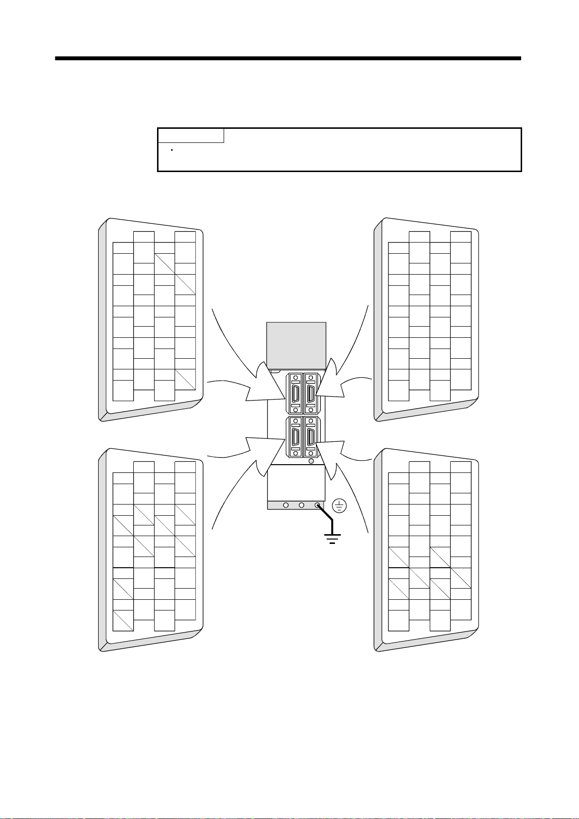
A
3. SIGNALS AND WIRING
3.3 I/O signals
3.3.1 Connectors and signal arrangements
(1) Signal arrangement
CN1
1
2
LG
NP
3
4
PP
P15R
5
6
LZ
LA
7
8
LB
DOG
9
10
COM
SG
POINT
The connector pin-outs shown above are viewed from the cable connector
wiring section side.
CN1B
12
14
OP
16
LAR
18
ZP
20
SG
11
OPC
13
15
LZR
17
LBR
19
Servo amplifier
2
VC
4
CPO
6
MEND
8
ST1
10
SG
1
LG
3
VDD
5
DI0
7
MD0
9
ST2
12
TLA
14
DI1
16
LSP
18
ALM
20
SG
11
P15R
13
COM
15
SON
17
LSN
19
RD
CN2 CN3
2
RXD
4
MO1
6
8
10
TRE
1
LG
3
LG
5
RDP
7
9
SDP
12
TXD
14
MO2
16
18
20
P5
11
LG
13
LG
15
RDN
17
19
SDN
LG
MD
10
1
2
LG
3
4
5
6
7
8
MR
9
BAT
12
LG
14
16
MDR
18
P5
20
P5
11
LG
13
15
17
MRR
19
P5
The connector frames are
connected with the PE (earth)
terminal inside the servo amplifier.
3 - 4
Page 54

3. SIGNALS AND WIRING
3.3.2 Signal (devices) explanations
(1) I/O devices
POINT
The devices not indicated in the Connector Pin No. field of the I/O devices
can be assigned to the connector CN1A/CN1B using the MR Configurator
(servo configuration software).
(a) Pins whose devices can be changed
Refer to section 3.6.2 for the I/O interfaces (symbols in the I/O Division field in the table) of the
corresponding connector pins.
Pin type Connector pin No. I/O division Device in initial status
CN1B-5 Point table No. selection 1 (DI0)
CN1B-14 Point table No. selection 2 (DI1)
CN1A-8 Proximity dog (DOG)
CN1B-15 Servo-on (SON)
Input-only pins
I/O pin CN1A-19 DI-1 or DO-1
Output-only pins
CN1B-16 Forward rotation stroke end (LSP)
CN1B-17 Reverse rotation stroke end (LSN)
CN1B-7 Automatic/manual selection (MD0)
CN1B-8 Forward rotation start (ST1)
CN1B-9
CN1B-4 Rough match (CPO)
CN1B-6 Movement finish (MEND)
CN1B-18 Trouble (ALM)
CN1B-19 Ready (RD)
CN1A-18
DI-1
Reverse rotation start (ST2)
No device has been assigned in the initial
status. You can assign an I/O device using
the MR Configurator (servo configuration
software).
DO-1
Home position return completion(ZP)
(b) Input devices
Device name
Forced stop EMG When EMG-SG are opened, the servo amplifier is placed in the forced stop status,
Servo-on SON CN1B
Reset RES Disconnect RES-SG for more than 50ms to reset the alarm.
Devices
symbol
Connector
pin No.
15
Functions/Applications
the servo switches off, and the dynamic brake is operated to bring the servo motor
to a sudden stop.
Short EMG-SG in the forced stop status to cancel the forced stop status.
Connect SON-SG to switch on the base circuit and make the servo amplifier ready
to operate (servo-on).
Disconnect SON-SG to shut off the base circuit and coast the servo motor (servooff) .
Some alarms cannot be deactivated by the reset signal. Refer to section 11.2.1
If RES-SG are shorted in no alarm status, the base circuit is not shut off.
Set "
1 " in parameter No. 55 to shut off the base circuit.
Since this device is not designed for stopping. Do not switch it on during operation.
3 - 5
Page 55

3. SIGNALS AND WIRING
Device name
Forward rotation
stroke end
Reverse rotation stroke
end
Forward rotation start ST1 CN1B 8 1. In the case of the absolute value command system.
Reverse rotation start ST2 CN1B 9 This device is used in the incremental value command system.
Automatic/manual
selection
Proximity dog DOG CN1A
Devices
symbol
LSN CN1B
MD0 CN1B 7 Short MD0-SG to choose the automatic operation mode, or open them to choose the
Connector
pin No.
LSP CN1B
To start operation, short LSP-SG and/or LSN-SG. Open them to bring the motor to
a sudden stop and make it servo-locked.
16
Set "
(Refer to section 5.2.5.)
(Note) Input signal Operation
1 1
0 1
17
1 0
0 0
Note. 0: LSP/LSN-SG off (open)
2. In the case of the incremental value command system.
3. In absolute value command /incremental value command specifying system
When ST2-SG are shorted in the automatic operation mode, positioning is executed
once in the reverse rotation direction on the basis of the position data set to the
point table.
In jog operation mode, the servo motor rotates in the reverse rotation direction
while ST2-SG are shorted.
Reverse rotation denotes the direction in which the address is decremented.
The reverse rotation start (ST2) is also used as the start signal of the function to
perform high-speed positioning to the home position. (Refer to section 4.4.11.)
manual operation mode.
When terminals DOG-SG are shorted, the proximity dog signal is detected. The
polarity of dog detection input can be changed with the parameter.
8
0 (initial value) DOG-SG are opened.
1 DOG-SG are shorted.
Functions/Applications
1" in parameter No. 22 to make a slow stop.
LSP LSN
1: SP/LSN-SG on (short)
When ST1-SG are shorted in the automatic operation mode, positioning is
executed once on the basis of the position data set to the point table.
In home position return mode, home position return starts as soon as ST1-SG
are shorted.
In jog operation mode, the servo motor rotates in the forward rotation direction
while ST1-SG are shorted.
Forward rotation denotes the direction in which the address is incremented.
When ST1-SG are shorted in the automatic operation mode, positioning is
executed once on the basis of the position data set to the point table.
In home position return mode, home position return starts as soon as ST1-SG
are shorted.
In jog operation mode, the servo motor rotates in the forward rotation direction
while ST1-SG are shorted.
Parameter No.8
CCW
direction
Polarity of proximity dog
detection input
direction
3 - 6
CW
Page 56

3. SIGNALS AND WIRING
Device name
Point table No.
selection 1
selection 2
selection 3
selection 4
Point table No.
selection 5
Override selection OVR Short OVR-SG to make override (VC) valid.
External torque limit
selection
Internal torque limit
selection
Proportion control PC Connect PC-SG to switch the speed amplifier from the proportional integral type to
Devices
symbol
Connector
pin No.
DI0 CN1B
DI1 CN1B
DI2
DI3
DI4
TL Short TL-SG to make external analog torque limit valid.
TL2 Open TL2-SG to make the torque limit value set in parameter No.28 (TL1) valid, or
The following table lists the point table numbers that may be chosen by the
combinations of DI0, DI1, DI2, DI3 and DI4.
5
14
0 0 0 0 1 1 Point table No.
0 0 0 1 0 2
0 0 0 1 1 3 Point table No.
0 0 1 0 0 4
0 0 1 0 1 5
0 0 1 1 0 6
0 0 1 1 1 7
0 1 0 0 0 8
0 1 0 0 1 9
0 1 0 1 0 10
0 1 0 1 1 11
0 1 1 0 0 12
0 1 1 0 1 13
0 1 1 1 0 14
0 1 1 1 1 15
1 0 0 0 0 16
1 0 0 0 1 17
1 0 0 1 0 18
1 0 0 1 1 19
1 0 1 0 0 20
1 0 1 0 1 21
1 0 1 1 0 22
1 0 1 1 1 23
1 1 0 0 0 24
1 1 0 0 1 25
1 1 0 1 0 26
1 1 0 1 1 27
1 1 1 0 0 28
1 1 1 0 1 29
1 1 1 1 0 30
1 1 1 1 1 31
For more information, refer to section 3.4.4.
short them to make the value set in parameter No.29 (TL2) valid.
For more information, refer to section 3.4.4.
the proportional type.
If the servo motor at a stop is rotated even one pulse due to any external factor, it
generates torque to compensate for a position shift. In such a case where the axis
will be locked mechanically after Movement finish (MEND) has turned off, turning
Proportion control (PC) on as soon as Movement finish (MEND) turns off can
suppress unnecessary torque that attempts to compensate for a position shift.
When the shaft is to be locked for a long time, switch on the proportion control (PC)
and torque (TL) at the same time to make the torque less than the rated by the
analog torque limit (TLA).
DI4 DI3 DI2 DI1 DI0
0 0 0 0 0
Note. 0: DI0/DI1/DI2/DI3/DI4-SG off (open)
1: DI0/DI1/DI2/DI3/DI4-SG on (short)
(Note)Input signal
Functions/Applications
Point table No.
0 (Manual home
position return)
Point table No.
3 - 7
Page 57
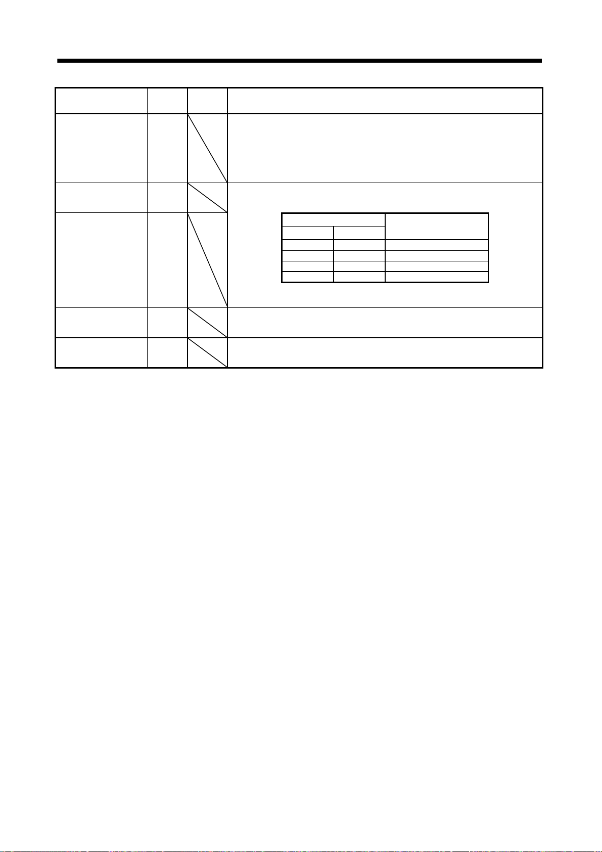
3. SIGNALS AND WIRING
Device name
Temporary
stop/Restart
Manual pulse
generator
multiplication 1
Manual pulse
generator
multiplication 2
Gain switch CDP Connect CDP-SG to change the load inertia moment ratio into the parameter No.
Teach TCH Used when performing teaching. Shorting TCH-SG in the teaching setting mode
Devices
symbol
Connector
pin No.
STP Short STP-SG during automatic operation to make a temporary stop. Short STP-
TP0 Used to select the multiplication factor of the manual pulse generator.
TP1
SG again to make a restart.
Shorting the forward rotation start (ST1) or reverse rotation start (ST2) during a
temporary stop is ignored. Switching from automatic operation mode to manual
operation mode during a temporary stop clears the remaining moving distance.
During home position return and jog operation, the temporary stop/restart input is
ignored. Refer to section 4.2.6 (3).
When it is not selected, the parameter No.1 setting is made valid.
0 0 Parameter No.1 setting
0 1 1 time
1 0 10 times
1 1 100 times
64 setting and the gain values into the values multiplied by the parameter No. 65
to 67 settings.
chooses this device and changes the position data of the point table No. to the
current position. (Refer to section 7.10.)
(Note) Input signal
TP1 TP0
Note. 0: TP1/TP0-SG open
1: TP1/TP0-SG shorted
Functions/Applications
Manual pulse generator
multiplication factor
3 - 8
Page 58

3. SIGNALS AND WIRING
(c) Output devices
Device name
Trouble ALM CN1B
Ready RD CN1B
Movement finish MEND CN1B 6 MEND-SG are connected when the in-position device (INP) turns on and the
Rough match CPO CN1B 4 CPO-SG are connected when the remaining command distance falls within the
Home position return
completion
Electromagnetic brake
interlock
Position range POT
Warning WNG When warning has occurred, WNG-SG are connected.
Battery warning BWNG
Limiting torque TLC
Temporary stop PUS
In position INP INP-SG are connected when the number of droop pulses is in the preset in-position
Devices
symbol
MBR
Connector
pin No.
ALM-SG are disconnected when power is switched off or the protective circuit is
18
activated to shut off the base circuit. Without alarm, ALM-SG are connected within
about 1s after power-on.
RD-SG are connected when the servo is switched on and the servo amplifier is
19
ready to operate.
command remaining distance is "0". (Refer to section 3.4.2.)
MEND-SG are connected at servo on.
parameter-set rough match output range.
This signal is not output while the base circuit is off. Servo-on connects CPO-SG.
During home position return and manual operation, CPO-SG are kept connected.
ZP CN1A
ZP-SG are connected on completion of home position return.
18
In the absolute position system, ZP-SG are connected when the servo amplifier is
ready to operate but are disconnected if.
1) SON-SG are opened.
2) EMG-SG are opened.
3) RES-SG are shorted.
4) Alarm occurs.
5) Limit switch opens.
6) Home position return has not been made after the purchase of the product.
7) Home position return has not been made after the occurrence of absolute position
8) Home position return has not been made after the changing of the electronic gear
9) Home position return has not been made after the absolute position system was
10) The ST1 coordinate system (000
11) Software limit is valid.
12) Home position return completion.
If the status is not any of 1) to 12) and the home position setting has already been
completed at least once, home position return completion (ZP) is placed in the same
output status as ready (RD).
In the servo-off or alarm status, MBR-SG are disconnected.
When an alarm occurs, they are disconnected independently of the base circuit
status.
Position range (POT) is on when the current position is within the range set in
parameters No. 50 to 53. If the current position is within the set range, the device
is off when a home position return is not yet
(during servo off, alarm occurrence or alarm reset).
When there is no warning, WNG-SG are disconnected within about 1s after power-
on.
BWNG-SG are connected when battery cable breakage warning (AL.92) or battery
warning (AL.9F) has occurred.
When there is no battery warning, BWNG-SG are disconnected within about 1s
after power-on.
TLC-SG are connected when the torque generated reaches the value set to the
internal torque limit 1 (parameter No. 28), internal torque limit 1 (parameter No.
29) or analog torque limit (TLA).
PUS-SG are connected when deceleration to a stop is started by the temporary stop
signal. PUS-SG is disconnected when operation is resumed by making the
temporary stop signal valid again.
range. The in-position range can be changed using parameter No. 6.
When the in-position range is increased, INP-SG may be kept connected during
low-speed rotation. Servo-on connects INP-SG.
Functions/Applications
erasure (AL. 25) or absolute position counter warning (AL. E3).
value.
made valid.
in parameter No.1) has been changed.
complete or while the base circuit is off
3 - 9
Page 59

3. SIGNALS AND WIRING
Device name
Point table No. output 1 PT0 As soon as Movement finish (MEND) turns on, the point table No. is output as a 5-
Point table No. output 5 PT4
Devices
symbol
Connector
pin No.
Functions/Applications
bit code.
(Note) Output signal Point table No. output 2 PT1
0 0 0 0 0 Point table No. output 3 PT2
1 0 0 0 0 1
2 0 0 0 1 0 Point table No. output 4 PT3
3 0 0 0 1 1
4 0 0 1 0 0
5 0 0 1 0 1
6 0 0 1 1 0
7 0 0 1 1 1
8 0 1 0 0 0
9 0 1 0 0 1
10 0 1 0 1 0
11 0 1 0 1 1
12 0 1 1 0 0
13 0 1 1 0 1
14 0 1 1 1 0
15 0 1 1 1 1
16 1 0 0 0 0
17 1 0 0 0 1
18 1 0 0 1 0
19 1 0 0 1 1
20 1 0 1 0 0
21 1 0 1 0 1
22 1 0 1 1 0
23 1 0 1 1 1
24 1 1 0 0 0
25 1 1 0 0 1
26 1 1 0 1 0
27 1 1 0 1 1
28 1 1 1 0 0
29 1 1 1 0 1
30 1 1 1 1 0
31 1 1 1 1 1
Note. 0: DI-SG open
In any of the following states, PT0 to PT4-SG are opened.
In any of the following states, PT0 to PT4 maintain the status (shorted/open) prior
to a change.
Point table No.
1: DI-SG shorted
Power on
Servo off
During home position return
Home position return completion
At operation mode changing
When the automatic/manual selection device (MD0) is turned from OFF to ON or
from ON to OFF to switch the operation mode.
During manual operation
During execution of automatic positioning to the home position
PT4 PT3 PT2 PT1 PT0
3 - 10
Page 60

3. SIGNALS AND WIRING
(2) Input signal
For the input interfaces (symbols in I/O column in the table), refer to section 3.6.2.
Signal
generator
Override VC CN1B-2 10 to 10V is applied to across VC-LG to limit the servo motor speed.
Analog torque limit TLA CN1B
Signal
symbol
Connector
pin No.
PP CN1A-3 Manual pulse
NP CN1A-2
Used to connect the manual pulse generator (MR-HDP01).
For details, refer to section 14.1.8.
Apply
To use this signal, set any of MR Configurator (servo configuration
12
software) to make the external torque limit selection (TL) available.
When the analog torque limit (TLA) is valid, torque is limited in the full
servo motor output torque range. Apply 0 to
Connect the positive terminal of the power supply to TLA. Maximum
torque is generated at
Functions/Applications
10[V] for 0[%] override, 0[V] for 100[%], or 10[V] for 200[%].
10VDC across TLA-LG.
10V. (Refer to in section 3.4.4.) Resolution:10bits
(3) Output signal
For the output interfaces (symbols in I/O column in the table), refer to section 3.6.2.
Signal
Encoder Z-phase pulse
(open collector)
Encoder A-phase pulse
(differential line driver)
Encoder B-phase pulse
(differential line driver)
Encoder Z-phase pulse
(differential line driver)
Analog monitor 1 MO1 CN3 4 Used to output the data set in parameter No.17 to across MO1-LG in
Analog monitor 2 MO2 CN3
Signal
symbol
Connector
pin No.
OP CN1A
LA
LAR
LB
LBR
LZ
LZR
CN1A
CN1A
CN1A
CN1A
CN1A
CN1A
Outputs the zero-point signal of the encoder. One pulse is output per
14
servo motor revolution. OP and LG are connected when the zero-point
position is reached. (Negative logic)
The minimum pulse width is about 400
using this pulse, set the creep speed to 100r/min. or less.
Outputs pulses per servo motor revolution set in parameter No. 27 in the
differential line driver system. In CCW rotation of the servo motor, the
6
encoder B-phase pulse lags the encoder A-phase pulse by a phase angle
of
16
The relationships between rotation direction and phase difference of the
A- and B-phase pulses can be changed using parameter No. 58.
7
17
The same signal as OP is output in the differential line driver system.
5
15
terms of voltage. Resolution 10 bits
Used to output the data set in parameter No.17 to across MO2-LG in
14
terms of voltage. Resolution 10 bits
Functions/Applications
s. For home position return
/2.
I/O
division
Analog
input
Analog
input
I/O
division
DO-2
DO-2
DO-2
DO-2
Analog
output
Analog
output
3 - 11
Page 61

3. SIGNALS AND WIRING
(4) Communication
POINT
Refer to chapter 15 for the communication function.
Signal
RS-422 I/F SDP
RS-422 termination TRE CN3
RS-232C I/F TXD
Signal
symbol
SDN
RDP
RDN
RXD
Connector
pin No.
CN3
9
CN3
19
CN3
5
CN3
15
10
CN3
2
CN3
12
Functions/Applications
RS-422 and RS-232C functions cannot be used together.
Choose either one in parameter No. 16.
Termination resistor connection terminal of RS-422 interface.
When the servo amplifier is the termination axis, connect this terminal to RDN
(CN3-15).
RS-422 and RS-232C functions cannot be used together.
Choose either one in parameter No. 16.
(5) Power supply
Signal
I/F internal power
supply
Digital I/F power
supply input
Open collector power
input
Digital I/F common SG CN1A
15VDC power supply P15R CN1A
Control common LG CN1A
Shield SD Plate Connect the external conductor of the shield cable.
Signal
symbol
VDD CN1B 3 Used to output 24V 10% to across VDD-SG.
COM CN1A
OPC CN1A
Connector
pin No.
9
CN1B
13
11
10
20
CN1B
10
20
4
CN1B
11
1
CN1B
1
CN3
1, 11
3, 13
Functions/Applications
When using this power supply for digital interface, connect it with COM.
Permissible current : 80mA
Used to input 24VDC (200mA or more) for input interface.
Connect the positive (
24VDC 10%
When you use a manual pulse generator , supply this terminal with the positive ( )
power of 24VDC.
Common terminal for input signals such as SON and EMG. Pins are connected
internally.
Separated from LG.
Outputs 15VDC to across P15R-LG. Available as power for VC and VLA.
Permissible current: 30mA
Common terminal for TLA, VC, OP, MO1, MO2 and P15R.
Pins are connected internally.
) terminal of the 24VDC external power supply.
3 - 12
Page 62

3. SIGNALS AND WIRING
3.4 Detailed description of signals (devices)
3.4.1 Forward rotation start
Reverse rotation start Temporary stop/restart
(1) A forward rotation start (ST1) or a reverse rotation start (ST2) should make the sequence which can
be used after the main circuit has been established. These signals are invalid if it is switched on before
the main circuit is established.
Normally, it is interlocked with the ready signal (RD).
(2) A start in the servo amplifier is made when the external start signal changes from OFF to ON. The
delay time of the servo amplifier's internal processing is max. 3ms. The delay time of other signals is
max. 10ms.
3ms or less
Servo motor speed
Forward rotation start (ST1)
or reverse rotation start (ST2)
Temporary stop/Restart (STP)
5ms or more
10ms
or less
3ms or less
(3) When a programmable controller is used, the ON time of the start/stop signal should be 5ms or longer
to prevent a malfunction.
(4) During operation, the forward rotation start (ST1) or reverse rotation start (ST2) is not accepted. The
next operation should always be started after the rough match (CPO) is output with the rough match
output range set to 0 or after the movement finish (MEND) is output.
3 - 13
Page 63

e
3. SIGNALS AND WIRING
3.4.2 Movement finish
Rough match In position
POINT
If an alarm cause, etc. are removed and servo-on occurs after a stop is
made by servo-off, alarm occurrence or Forced stop (EMG) ON during
automatic operation, Movement finish (MEND), Rough-match, (CPO) and
In position (INP) are turned on. To resume operation, confirm the current
position and the selected point table No. for preventing unexpected
operation.
(1) Movement finish
The following timing charts show the output timing relationships between the position command
generated in the servo amplifier and the movement finished (MEND). This timing can be changed
using parameter No. 6 (in-position range). MEND-SG are connected in the servo-on status.
Forward rotation start (ST1)
or reverse rotation start (ST2)
Position command and
servo motor speed
Movement finish (MEND)
ON
OFF
3ms or less
ON
OFF
Position command
When parameter No. 6 is small
Servo motor speed
In-position range
Forward rotation start (ST1)
or reverse rotation start (ST2)
Position command and
servo motor speed
ON
OFF
3ms or less
Position command
Servo motor speed
In-position range
Movement finish (MEND)
ON
OFF
When parameter No. 6 is large
(2) Rough match
The following timing charts show the relationships between the signal and the position command
generated in the servo amplifier. This timing can be changed using parameter No. 12 (rough match
output range). CPO-SG are connected in the servo-on status.
Forward rotation start
(ST1) or
reverse rotation start
(ST2)
Position command
Rough match (CPO)
When "0" is set in parameter No. 12 When more than "0" is set in parameter No. 12
ON
OFF
3ms or less
ON
OFF
Forward rotation start
(ST1) or
reverse rotation start
(ST2)
Position command
Rough match (CPO)
ON
OFF
3ms or less
ON
OFF
Rough match output rang
3 - 14
Page 64

3. SIGNALS AND WIRING
(3) In position
The following timing chart shows the relationship between the signal and the feedback pulse of the
servo motor. This timing can be changed using parameter No. 6 (in-position range). INP-SG are
connected in the servo-on status.
Forward rotation start (ST1)
or reverse rotation start (ST2)
Servo motor speed
ON
OFF
3ms or less
In-position range
In position (INP)
ON
OFF
When positioning operation is performed once
Forward rotation start (ST1)
or reverse rotation start (ST2)
Forward
rotation
Servo motor speed
Reverse
rotation
In position (INP)
When servo motor reverses rotation direction during automatic continuous operation
ON
OFF
3ms or less
ON
OFF
In-position range
3 - 15
Page 65
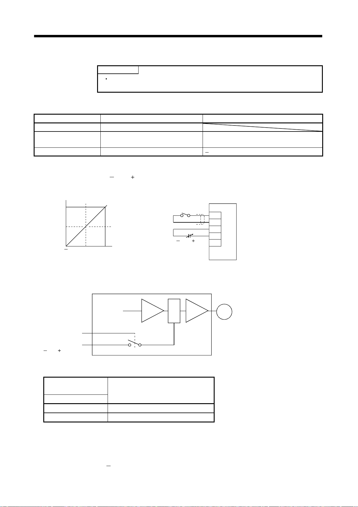
3. SIGNALS AND WIRING
3.4.3 Override
POINT
When using the override (VC), make the override selection (OVR) device
available.
The override (VC) may be used to change the servo motor speed. The following table lists the signals and
parameter related to the override.
Item Name Remarks
Analog input signal Override (VC)
Contact input signal Override selection (OVR)
Parameter No.25 override offset 999 to 999mV
MR Configurator (servo configuration software)
setting required.
(1) Override (VC)
By applying a voltage (
10 to 10V) to the override (VC) terminal, change values can be set from
outside consecutively. The following graph shows the relationship between the input voltage and the
ratio of actual speed to preset speed.
[%]
200
100
0
Ratio of actual speed to
preset speed
Override (VC) application voltage
10
0
10
Override selection (OVR)
Override (VC)
[V]
10 to 10V
Servo amplifier
OVR
SG
VC
LG
SD
(2) Override selection (OVR)
Used to make the override (VC) valid or invalid.
Servo amplifier
Motor
Override
Override selection
(OVR)
Override (VC)
10 to 10V
Using the override selection (OVR), choose a change value as follows.
(Note)
External input signal
OVR
0 No change
1 Override (VC) setting is made valid.
Note. 0 : Off (open) across OVR-SG
1 : On (shorted) across OVR-SG
Speed change value
(3) Override offset (parameter No.25)
Using parameter No.25, the offset voltage can be set relative to the input voltage for the override (VC).
The setting is between
999 to 999mV.
3 - 16
Page 66

r
3. SIGNALS AND WIRING
3.4.4 Torque limit
POINT
To use the torque limit, make the external torque limit selection (TL) and
internal torque limit selection (TL2) available.
The following table lists the signals and parameters related to the torque limit.
Item Name Remarks
Analog input signal Analog torque limit (TLA)
Contact input signals
Contact output signal Limiting torque (TLC)
Parameters
External torque limit selection (TL)
Internal torque limit selection (TL2)
No.28 (internal torque limit 1) 0 to 100%
No.29 (internal torque limit 2) 0 to 100%
No.26 (torque limit offset) 999 to 999mV
No.59 (function selection 2)
MR Configurator (servo configuration
software) setting required.
Selection of the rotation direction in which
torque limit is executed
The torque limit is available in two types: internal torque limit set in parameters and analog torque limit
(TLA) using analog input signal. This function limits torque on the assumption that the maximum torque
of the servo motor is 100%.
(1) Internal torque limits 1, 2
Use parameter No.28 and 29 to set the internal torque limit values. The following graph shows the
torque relative to the setting.
Max. torque
Torque
0
0100
Torque limit value [%]
(2) Analog torque limit (TLA)
By applying a voltage (0 to 10V) to the analog torque limit (TLA) terminal, limit values can be set from
outside consecutively. The following graph shows the relationship between input voltage and limit
value.
Depending on the servo amplifier, the limit value has about 5% variations to the input voltage. As this
may not cause torque to be limited sufficiently at less than 0.05V, use this function at the voltage of
0.05V or more.
Refer to the following diagram when using the 15V power output (P15R) of the servo amplifier:
100
5%
0
Torque limit value [%]
010
0.05
TLA application voltage [V]
TLA Application Voltage vs.
Torque Limit Value
2k
Japan Resistor RRS10
or equivalent
2k
Connection Example
Servo amplifie
TL
SG
P15R
TLA
LG
SD
3 - 17
Page 67

3. SIGNALS AND WIRING
(3) External torque limit selection (TL), internal torque limit selection (TL2)
To use the external torque limit selection (TL) and internal torque limit selection (TL2), make them
available using the MR Configurator (servo configuration software) (refer to chapter 6).
These input signals may be used to choose the torque limit values made valid.
(Note) External input signals
TL2 TL
0 0 Internal torque limit value 1 (parameter No. 28)
0 1
1 0
1 1
Note. 0: TL/TL2-SG off (open)
1: TL/TL2-SG on (short)
Parameter No. 29
Parameter No. 29
Torque limit value made valid
TLA
Parameter No. 28: Parameter No. 28
TLA
Parameter No. 28: TLA
Parameter No. 28: Parameter No. 28
Parameter No. 28: Parameter No. 29
TLA
Parameter No. 29: Parameter No. 29
TLA
Parameter No. 29: TLA
(4) External torque limit offset (parameter No.26)
Using parameter No.26, the offset voltage can be set relative to the input voltage of the analog torque
limit (TLA). The setting is between
999 to 999mV.
(5) Selection of rotation direction for torque limit execution (parameter No.59)
Using parameter No.59, the rotation direction for torque limit execution can be selected.
Parameter No.59 setting
0 (initial value)
1
2
Rotation direction for torque limit execution
CCW direction CW direction
For example, when “
1 ” is set in parameter No.59, torque limit is executed in the CCW direction
but not in CW direction.
CCW rotation: Torque limit is executed.
CW rotation: Torque limit is not executed.
3 - 18
Page 68

3. SIGNALS AND WIRING
3.5 Alarm occurrence timing chart
When an alarm has occurred, remove its cause, make sure that the operation
signal is not being input, ensure safety, and reset the alarm before restarting
CAUTION
operation.
As soon as an alarm occurs, turn off Servo-on (SON) and power off.
When an alarm occurs in the servo amplifier, the base circuit is shut off and the servo motor is coated to a
stop. Switch off the main circuit power supply in the external sequence. To reset the alarm, switch the
control circuit power supply from off to on, press the "SET" button on the current alarm screen, or turn
the reset (RES) from off to on. However, the alarm cannot be reset unless its cause is removed.
(Note)
Main circuit
control circuit
power supply
Base circuit
Dynamic brake
Servo-on
(SON)
Ready
Trouble
(ALM)
Reset
(RES)
Note. Switch off the main circuit power as soon as an alarm occurs.
(RD)
ON
OFF
ON
OFF
Valid
Invalid
ON
OFF
ON
OFF
ON
OFF
ON
OFF
1s
Alarm occurs.
Remove cause of trouble.
Brake operation
50ms or more
Power off
Brake operation
60ms or more
Power on
(1) Overcurrent, overload 1 or overload 2
If operation is repeated by switching control circuit power off, then on to reset the overcurrent
(AL.32), overload 1 (AL.50) or overload 2 (AL.51) alarm after its occurrence, without removing
its cause, the servo amplifier and servo motor may become faulty due to temperature rise.
Securely remove the cause of the alarm and also allow about 30 minutes for cooling before
resuming operation.
(2) Regenerative alarm
If operation is repeated by switching control circuit power off, then on to reset the regenerative
(AL.30) alarm after its occurrence, the external regenerative resistor will generate heat,
resulting in an accident.
(3) Instantaneous power failure
Undervoltage (AL.10) occurs when the input power is in either of the following statuses.
A power failure of the control circuit power supply continues for 60ms or longer and the
control circuit is not completely off.
The bus voltage dropped to 200VDC or less for the MR-J2S- CP, or to 158VDC or less for the
MR-J2S-
CP1.
(4) Incremental system
When an alarm occurs, the home position is lost. When resuming operation after deactivating
the alarm, make a home position return.
3 - 19
Page 69

3. SIGNALS AND WIRING
3.6 Interfaces
3.6.1 Common line
The following diagram shows the power supply and its common line.
Dl-1
Manual pulse generator
MR-HDP01
5V
A(B)
0V
5V
Analog input
( 10V/max. current)
CN1A
CN1B
VDD
COM
SON,etc.
SG
OPC
PP(NP)
SG
<Isolated>
15VDC 10% 30mA
P15R
TLA
VC,
etc.
LG
SD
24VDC
ALM,etc
LA,etc
SG
OP
LG
LAR,etc
LG
SD
MO1
MO2
LG
SDP
SDN
RDP
RDN
LG
SD
CN1A
CN1B
CN3
RA
DO-1
Differential line driver
output
35mA or less
Analog monitor
RXD
RXD
TXD
TXD
LG
Single-phase
100 to 200VAC
1
L
L
2
E
Servo motor
M
Ground
3 - 20
MR
MRR
SD
CN2
Servo motor encoder
Page 70

3. SIGNALS AND WIRING
3.6.2 Detailed description of the interfaces
This section gives the details of the I/O signal interfaces (refer to I/O Division in the table) indicated in
sections 3.3.2. Refer to this section and connect the interfaces with the external equipment.
(1) Digital input interface DI-1
Give a signal with a relay or open collector transistor. Source input is also possible. Refer to (6) of this
section.
For use of internal power supply For use of external power supply
Servo amplifier
Do not connect
VDD-COM.
24VDC
200mA or more
Servo amplifier
VDD
COM
SON, etc.
24VDC
R: Approx. 4.7k
(Note)
For a transistor
Approx. 5mA
Switch
VDD
COM
SON, etc.
24VDC
R: Approx. 4.7k
SGTR
V
CES 1.0V
I
100 A
CEO
Note. This also applies to the use of the external power supply.
Switch
SG
(2) Digital output interface DO-1
A lamp, relay or photocoupler can be driven. Provide a diode (D) for an inductive load, or an inrush
current suppressing resister (R) for a lamp load. (Permissible current: 40mA or less, inrush current:
100mA or less) A maximum of 2.6V voltage drop occurs in the servo amplifier.
(a) Inductive load
For use of internal power supply For use of external power supply
Servo amplifier
24VDC
ALM, etc
VDD
COM
Load
Servo amplifier
24VDC
ALM, etc
VDD
COM
Do not connect
VDD-COM.
(Note)
Load
24VDC
10%
SG
If the diode is not
connected as shown,
the servo amplifier
will be damaged.
Note. If the voltage drop (maximum of 2.6V) interferes with the
relay operation, apply high voltage (up to 26.4V) from
external source.
SG
If the diode is not
connected as shown,
the servo amplifier
will be damaged.
3 - 21
Page 71

r
A
3. SIGNALS AND WIRING
(b) Lamp load
For use of internal power supply For use of external power supply
Servo amplifier
24VDC
VDD
COM
ALM, etc
SG
(3) Encoder pulse output DO-2
(a) Open collector system
Interface
Max. output current : 35m
Servo amplifier
OP
LG
Servo amplifier
24VDC
R
VDD
COM
ALM, etc
SG
Note. If the voltage drop (maximum of 2.6V) interferes with the
relay operation, apply high voltage (up to 26.4V) from
external source.
Servo amplifier
OP
LG
Do not connect
VDD-COM.
R
5 to 24VDC
Photocouple
(Note)
24VDC
10%
SD
(b) Differential line driver system
1) Interface
Max. output current: 35mA
Servo amplifier Servo amplifier
LA
(LB, LZ)
LAR
(LBR, LZR)
LG
SD
Am26LS32 or equivalent High-speed photocoupler
150
LA
(LB, LZ)
LAR
(LBR, LZR)
SD
SD
100
3 - 22
Page 72

r
3. SIGNALS AND WIRING
2) Output pulse
Servo motor CCW rotation
LA
LAR
LB
LBR
LZ
LZR
OP
T
/2
(4) Analog input
Input impedance 10k to 12k
Upper limit setting 2k
2k
(5) Analog output
Output voltage
10V
Max.1mA
Max. output current
Resolution : 10bits
Servo amplifie
400 s or more
Servo amplifier
P15R
VC‚ etc
LG
SD
The time cycle (T) is determined by
the setting of the parameter No. 27 and 58.
15VDC
Approx.
10k
MO1
(MO2)
LG
SD
10k
Reading in one or
both directions
1mA meter
A
3 - 23
Page 73
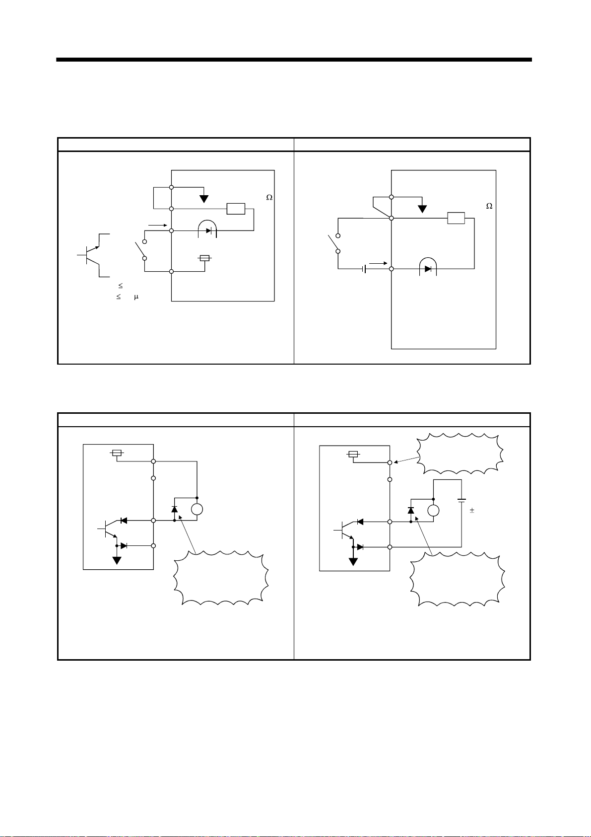
3. SIGNALS AND WIRING
(6) Source input interface
When using the input interface of source type, all Dl-1 input signals are of source type. Source output
cannot be provided.
For use of internal power supply For use of external power supply
Servo amplifier
SG
R: Approx. 4.7k
24VDC
Switch
COM
SON,
etc.
VDD
(Note)
For a transistor
Approx. 5mA
TR
1.0V
V
CES
100 A
I
CEO
Note. This also applies to the use of the external power supply.
Since source output is not provided, make the following circuit.
For use of internal power supply For use of external power supply
Servo amplifier
24VDC
VDD
Switch
24VDC
200mA or more
Servo amplifier
24VDC
VDD
Servo amplifier
SG
COM
SON,etc.
R: Approx. 4.7k
Do not connect
VDD-COM.
COM
ALM, etc
SG
Load
If the polarity of diode
is not correct, the
servo amplifier will
become faulty.
Note. If the voltage drop (maximum of 2.6V) interferes with the
relay operation, apply high voltage (up to 26.4V) from
external source.
COM
ALM, etc
SG
(Note)
Load
If the polarity of diode
is not correct, the
servo amplifier will
become faulty.
24VDC
10%
3 - 24
Page 74

3. SIGNALS AND WIRING
3.7 Input power supply circuit
Always connect a magnetic contactor (MC) between the main circuit power supply
1, L2, and L3 of the servo amplifier, and configure the wiring to be able to shut
and L
down the power supply on the side of the servo amplifier’s power supply. If a
CAUTION
magnetic contactor (MC) is not connected, continuous flow of a large current may
cause a fire when the servo amplifier malfunctions.
Use the trouble signal to switch power off. Otherwise, a regenerative transistor
fault or the like may overheat the regenerative resistor, causing a fire.
3.7.1 Connection example
Wire the power supply and main circuit as shown below so that the servo-on (SON) turns off as soon as
alarm occurrence is detected and power is shut off.
A circuit breaker (NFB) must be used with the input cables of the power supply.
(1) For 3-phase 200 to 230VAC power supply
RA
Forced
stop
OFF
ON
MC
MC
SK
NFB MC
3-phase
200 to 230 VAC
Forced stop
Servo-on
Servo amplifier
L
1
L2
L3
L
11
L
21
EMG
SON
SG
VDD
COM
ALM RA
Trouble
3 - 25
Page 75

3. SIGNALS AND WIRING
(2) For 1-phase 100 to 120VAC or 1-phase 230VAC power supply
RA
Forced
stop
OFF
ON
MC
MC
SK
Power supply
1-phase 100 to
120VAC or
1-phase 230VAC
NFB MC
L
L
L
L
L
Forced stop
Servo-on
Note : Not provided for 1-phase 100 to 120VAC.
EMG
SON
SG
Servo amplifier
1
2
(Note)
3
11
21
VDD
COM
ALM RA
Trouble
3 - 26
Page 76

3. SIGNALS AND WIRING
3.7.2 Terminals
The positions and signal arrangements of the terminal blocks change with the capacity of the servo
amplifier. Refer to section 12.1.
Symbol
L1, L2, L3 Main circuit power supply
U, V, W Servo motor output
L11, L21 Control circuit power supply
P, C, D Regenerative option
N
Connection Target
(Application)
Return converter
Brake unit
Supply L1, L2 and L3 with the following power.
For 1-phase 230VAC, connect the power supply to L
Servo amplifier
Power supply
3-phase 200 to 230VAC,
50/60Hz
1-phase 230VAC,
50/60Hz
1-phase 100 to 120VAC,
50/60Hz
Connect to the servo motor power supply terminals (U, V, W).
During power-on, do not open or close the motor power line. Otherwise, a
malfunction or faulty may occur.
Servo amplifier
Power supply
1-phase 200 to 230VAC,
50/60Hz
1-phase 100 to 120VAC,
50/60Hz
1) MR-J2S-350CP or less
When using servo amplifier built-in regenerative resistor, connect between P-D
terminals. (Wired by default)
When using regenerative option, disconnect between P-D terminals and
connect regenerative option to P terminal and C terminal.
2) MR-J2S-500CP or 700CP
MR-J2S-500CP and 700CP do not have D terminal.
When using servo amplifier built-in regenerative resistor, connect P terminal
and C terminal. (Wired by default)
When using regenerative option, disconnect P terminal and C terminal and
connect regenerative option to P terminal and C terminal.
Refer to section 14.1.1 for details.
When using brake unit, connect to P terminal and N terminal.
Do not connect to servo amplifier MR-J2S-200CP or less.
For details, refer to section 14.1.2, 14.1.3.
Description
and leave L3 open.
1/L2
MR-J2S-10CP
to 70CP
L
1L2
L
MR-J2S-10CP to
L
MR-J2S-100CP
to 700CP
L
1L2L3
700CP
11 L21
L
MR-J2S-10CP1
to 40CP1
MR-J2S-10CP1 to
40CP1
11 L21
1L2
Protective earth (PE)
Connect this terminal to the protective earth (PE) terminals of the servo motor
and control box for grounding.
3 - 27
Page 77

3. SIGNALS AND WIRING
3.7.3 Power-on sequence
(1) Power-on procedure
1) Always wire the power supply as shown in above section 3.7.1 using the magnetic contactor with
the main circuit power supply (three-phase 200V: L
100V: L
1, L2). Configure up an external sequence to switch off the magnetic contactor as soon as an
1, L2, L3, single-phase 230V single-phase
alarm occurs.
2) Switch on the control circuit power supply L
11, L21 simultaneously with the main circuit power
supply or before switching on the main circuit power supply. If the main circuit power supply is not
on, the display shows the corresponding warning. However, by switching on the main circuit power
supply, the warning disappears and the servo amplifier will operate properly.
3) The servo amplifier can accept the servo-on (SON) about 1 to 2s after the main circuit power supply
is switched on. Therefore, when servo-on (SON) is switched on simultaneously with the main circuit
power supply, the base circuit will switch on in about 1 to 2s, and the ready (RD) will switch on in
further about 20ms, making the servo amplifier ready to operate. (Refer to paragraph (2) of this
section.)
4) When the reset (RES) is switched on, the base circuit is shut off and the servo motor shaft coasts.
(2) Timing chart
SON accepted
(1 to 2s)
Power supply
ON
OFF
(RD)
ON
OFF
ON
OFF
ON
OFF
ON
OFF
10ms10ms
60ms
20ms 20ms 20ms10ms 10ms
60ms
10ms
Base circuit
Servo-on
(SON)
Reset
(RES)
Ready
(3) Forced stop
Provide an external forced stop circuit to ensure that operation can be stopped and
CAUTION
power switched off immediately.
Forced stop (EMG) can be used by making device setting on the MR Configurator (servo configuration
software).
Make up a circuit which shuts off main circuit power as soon as EMG-SG are opened at a forced stop.
To ensure safety, always install an external forced stop switch across EMG-SG. By disconnecting
EMG-SG, the dynamic brake is operated to bring the servo motor to a sudden stop. At this time, the
display shows the servo forced stop warning (AL.E6).
During ordinary operation, do not use the external forced stop (EMG) to alternate stop and run.
The servo amplifier life may be shortened.
Servo amplifier
Forced stop
VDD
COM
EMG
SG
3 - 28
Page 78

3. SIGNALS AND WIRING
3.8 Connection of servo amplifier and servo motor
3.8.1 Connection instructions
WARNING
shock.
Connect the wires to the correct phase terminals (U, V, W) of the servo amplifier
and servo motor. Otherwise, the servo motor will operate improperly.
Insulate the connections of the power supply terminals to prevent an electric
CAUTION
Do not connect AC power supply directly to the servo motor. Otherwise, a fault
may occur.
POINT
Do not apply the test lead bars or like of a tester directly to the pins of the
connectors supplied with the servo motor. Doing so will deform the pins,
causing poor contact.
The connection method differs according to the series and capacity of the servo motor and whether or not
the servo motor has the electromagnetic brake. Perform wiring in accordance with this section.
(1) For grounding, connect the earth cable of the servo motor to the protective earth (PE) terminal of the
servo amplifier and connect the ground cable of the servo amplifier to the earth via the protective
earth of the control box. Do not connect them directly to the protective earth of the control panel.
Control box
Servo
amplifier
PE terminal
Servo motor
(2) Do not share the 24VDC interface power supply between the interface and electromagnetic brake.
Always use the power supply designed exclusively for the electromagnetic brake.
3.8.2 Connection diagram
During power-on, do not open or close the motor power line. Otherwise, a
CAUTION
malfunction or faulty may occur.
The following table lists wiring methods according to the servo motor types. Use the connection diagram
which conforms to the servo motor used. For cables required for wiring, refer to section 14.2.1. For
encoder cable connection, refer to section 14.1.4. For the signal layouts of the connectors, refer to section
3.8.3.
For the servo motor connector, refer to chapter 3 of the Servo Motor Instruction Manual.
3 - 29
Page 79

3. SIGNALS AND WIRING
Servo motor Connection diagram
HC-KFS053 (B) to 73 (B)
HC-MFS053 (B) to 73 (B)
HC-UFS13 (B) to 73 (B)
Servo amplifier
U
V
W
CN2
U (Red)
V (White)
W (Black)
(Green)
EMG
24VDC
B1
B2
(Note 1)
To be shut off when servo-on (SON)
switches off or by Trouble (ALM)
Servo motor
Motor
(Note 2)
Electromagnetic
brake
HC-SFS121 (B) to 301 (B)
HC-SFS202 (B) to 702 (B)
HC-SFS203 (B)
353 (B)
HC-UFS202 (B) to 502 (B)
HC-RFS353 (B) to 503 (B)
Encoder cable
Encoder
Note 1. To prevent an electric shock, always connect the protective earth (PE) terminal ( ) of the
servo amplifier to the protective earth (PE) of the control box.
2. This circuit applies to the servo motor with electromagnetic brake.
Servo amplifier
U
V
W
CN2
(Note 1)
To be shut off when servo-on (SON)
switches off or by Trouble (ALM)
24VDC
EMG
Encoder cable
Servo motor
U
V
W
B1
B2
Motor
Electromagnetic
brake
Encoder
(Note 2)
Note 1. To prevent an electric shock, always connect the protective earth (PE) terminal ( ) of the
servo amplifier to the protective earth (PE) of the control box.
2. This circuit applies to the servo motor with electromagnetic brake.
Servo amplifier
U
V
W
Servo motor
U
V
W
Motor
HC-SFS81(B)
HC-SFS52 (B) to 152 (B)
HC-SFS53 (B) to 153 (B)
HC-RFS103 (B) to 203 (B)
HC-UFS72 (B)
152 (B)
(Note 1)
To be shut off when servo-on (SON)
switches off or by Trouble (ALM)
CN2
24VDC
EMG
Encoder cable
B1
B2
Electromagnetic
brake
Encoder
(Note 2)
Note 1. To prevent an electric shock, always connect the protective earth (PE) terminal ( ) of the
servo amplifier to the protective earth (PE) of the control box.
2. This circuit applies to the servo motor with electromagnetic brake.
3 - 30
Page 80

3. SIGNALS AND WIRING
3.8.3 I/O terminals
(1) HC-KFS
Power supply
connector
5557-04R-210
HC-MFS HC-UFS3000r/min series
Power supply lead
4-AWG19 0.3m (0.98ft.)
Power supply connector (Molex)
Encoder cable 0.3m (0.98ft.)
With connector 1-172169-9
(Tyco Electronics)
Pin
1
a
13
24
View b
2
3
4
Signal
U
V
W
(Earth)
Without electromagnetic brake
5557-04R-210 (receptacle)
5556PBTL (Female terminal)
b
With electromagnetic brake
5557-06R-210 (receptacle)
5556PBTL (Female terminal)
Power supply
connector
5557-06R-210
1
4
25
36
View b
Encoder connector signal arrangement
123
MR
MRR BAT
456
MD
MDR
789
P5
LG SHD
View a
Signal
Pin
1
U
2
V
3
W
4
(Earth)
5
(Note)
B1
6
(Note)
B2
Note:For the motor with
electromagnetic brake,
supply electromagnetic
brake power (24VDC).
There is no polarity.
3 - 31
Page 81

t
3. SIGNALS AND WIRING
(2) HC-SFS
HC-RFS HC-UFS2000 r/min series
a
Encoder connector
b
Brake conn ector Power supply conn ector
c
Power supply connector signal arrangement
Servo motor
HC-SFS81(B)
HC-SFS52(B) to 152(B)
HC-SFS53(B) to 153(B)
HC-SFS121(B) to 301(B)
HC-SFS202(B) to 502 (B)
HC-SFS203(B) 353(B)
HC-SFS702(B)
HC-RFS103(B) to 203 (B)
HC-RFS353(B) 503(B)
HC-UFS72(B) 152(B)
HC-UFS202(B) to 502(B)
Servo motor side connectors
For power supply For encoder
CE05-2A2223PD-B
CE05-2A2410PD-B
CE05-2A3217PD-B
CE05-2A2223PD-B
CE05-2A2410PD-B
CE05-2A2223PD-B
CE05-2A2410PD-B
MS3102A2029P
Electromagnetic
brake connector
The connector
for power is
shared.
MS3102A10SL4P
The connector
for power is
shared.
MS3102A10SL4P
CE05-2A22-23PD-B
F
E
Encoder connector signal arrangement
MS3102A20-29P
L
K
Key
G
H
D
View c
Key
M B
T P
J
S
H
View a
CE05-2A32-17PD-B
U
V
B2
D
CB
A
Pin
A
B
C
D
Signal
U
V
W
(Earth)
Pin
A
B
C
A
B
C
D
Signal
U
V
W
(Earth)
E
F
(Note) B1
G
(Note)
H
B2
Note:For the motor with
electromagnetic brake,
supply electromagnetic
brake power (24VDC).
There is no polarity.
CE05-2A24-10PD-B
Key Key
A
F
E
D
B
G
C
View c
Pin
A
B
C
D
E
F
Signal
W
(Earth)
(Note) B1
(Note)
G
Note:For the motor with
electromagnetic brake,
supply electromagnetic
brake power (24VDC).
There is no polarity.
Electromagnetic brake connector signal arrangemen
MS3102A10SL-4P
Key
Pin
A
C
N
D
E
R
F
G
Signal
A
MD
B
MDR
C
MR
D
MRR
E
F
BAT
F
G
LG
H
Pin
K
L
M
N
P
R
S
T
Signal
AB
SD
View b
LG
P5
J
Pin
A
B
Signal
(Note)B1
(Note)
B2
Note:For the motor with
electromagnetic brake,
supply electromagnetic
brake power (24VDC).
There is no polarity.
3 - 32
Page 82
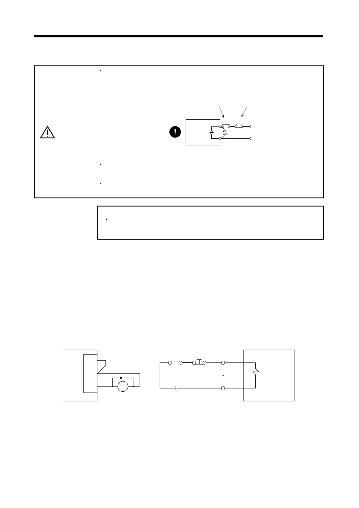
3. SIGNALS AND WIRING
3.9 Servo motor with electromagnetic brake
Configure the electromagnetic brake operation circuit so that it is activated not only
by the servo amplifier signals but also by an external forced stop (EMG).
Contacts must be open when
servo-on (SON) is off or when a trouble (ALM)
is present when a electromagnetic brake
interlock (MBR).
Servo motor
CAUTION
Electromagnetic brake
Circuit must be
opened during
forced stop (EMG).
EMGRA
24VDC
The electromagnetic brake is provided for holding the motor shaft. Do not use it for
ordinary braking.
Before performing the operation, be sure to confirm that the electromagnetic brake
operates properly.
POINT
For the power supply capacity, operation delay time and other
specifications of the electromagnetic brake, refer to the Servo Motor
Instruction Manual.
Note the following when the servo motor equipped with electromagnetic brake is used.
1) In the device setting of the MR Configurator (servo configuration software), make the
electromagnetic brake interlock (MBR) available.
2) Do not share the 24VDC interface power supply between the interface and electromagnetic brake.
Always use the power supply designed exclusively for the electromagnetic brake.
3) The brake will operate when the power (24VDC) switches off.
4) While the reset (RES) is on, the base circuit is shut off. When using the servo motor with a vertical
shaft, use the electromagnetic brake interlock (MBR).
5) Turn off the servo-on (SON) after the servo motor has stopped.
(1) Connection diagram
Servo amplifier
VDD
RA
Forced
stop
B1
Servo motor
COM
MBR
RA
24VDC
B2
Z
(2) Setting
1) In the device setting of the MR Configurator (servo configuration software), make the
electromagnetic brake interlock (MBR) available.
2) Using parameter No. 33 (electromagnetic brake sequence output), set a time delay (Tb) at servo-off
from electromagnetic brake operation to base circuit shut-off as in the timing chart shown in (3) of
this section.
3 - 33
Page 83

3. SIGNALS AND WIRING
(3) Timing charts
(a) Servo-on (SON) command (from controller) ON/OFF
Tb (ms) after servo-on (SON) is switched off, servo lock is released and the servo motor coasts.
If the electromagnetic brake is made valid in the servo lock status, the brake life may be shorter.
For use in vertical lift and similar applications, therefore, set delay time (Tb) to the time which is
about equal to the electromagnetic brake operation delay time and during which the load will not
drop.
Servo motor speed
Base circuit
Electromagnetic
brake interlock
(MBR)
Servo-on(RYn0)
Forward rotation start
(ST1) or reverse rotation
start (ST2)
Electromagnetic
brake
Note 1. ON: Electromagnetic brake is not activated.
OFF: Electromagnetic brake is activated.
2. Electromagnetic brake is released after delaying for the release delay time of electromagnetic brake and operation time of
external circuit relay. For the release delay time of electromagnetic brake, refer to the Servo Motor Instruction Manual.
3. After the electromagnetic brake is released, turn ON the ST1 or ST2.
0 r/min
(Note 1)
Release
Activate
ON
OFF
ON
OFF
ON
OFF
ON
OFF
(60ms)
(80ms)
(Note 3)
Release delay time and external relay (Note 2)
Coasting
Tb
(b) Forced stop (EMG) ON/OFF
Dynamic brake
Dynamic brake
Servo motor speed
Base circuit
Electromagnetic
brake interlock (MBR)
Forced stop (EMG)
Forward
rotation
0r/min
ON
OFF
ON
(Note)
OFF
(ON)
Invalid
Valid (OFF)
(10ms)
Electromagnetic brake
Electromagnetic brake
Electromagnetic brake release
(180ms)
(180ms)
Electromagnetic brake
operation delay time
Electromagnetic
brake operation
delay time
Note. ON: Electromagnetic brake is not activated.
OFF: Electromagnetic brake is activated.
3 - 34
Page 84

3. SIGNALS AND WIRING
(c) Alarm occurrence
Dynamic brake
Servo motor speed
Base circuit
Electromagnetic
brake interlock (MBR)
Trouble (ALM)
Note. ON: Electromagnetic brake is not activated.
OFF: Electromagnetic brake is activated.
Forward
rotation
0r/min
ON
OFF
ON
(Note)
OFF
(ON)
No
Yes (OFF)
(10ms)
(d) Both main and control circuit power supplies off
(10ms)(10ms)
(Note 1)
15 to 60ms
Servo motor speed
Forward
rotation
0r/min
Dynamic brake
Electromagnetic brake
Electromagnetic brake
Electromagnetic brake
operation delay time
Dynamic brake
Dynamic brake
Electromagnetic brake
Electromagnetic brake
Base circuit
Electromagnetic
brake interlock (MBR)
Trouble (ALM)
Main circuit
Control circuit
Note 1. Changes with the operating status.
2. ON: Electromagnetic brake is not activated.
OFF: Electromagnetic brake is activated.
(Note 2)
power
ON
OFF
ON
OFF
No
(ON)
Yes (OFF)
ON
OFF
Electromagnetic brake
operation delay time
3 - 35
Page 85

3. SIGNALS AND WIRING
(e) Only main circuit power supply off (control circuit power supply remains on)
Dynamic brake
Dynamic brake
Electromagnetic brake
Electromagnetic brake
Electromagnetic brake
operation delay time
(Note 2)
Servo motor speed
Base circuit
Electromagnetic
brake interlock (MBR)
Trouble (ALM)
Forward
rotation
(Note 3)
No
Yes (OFF)
(10ms)(10ms)
(Note 1)
15 or more
0r/min
ON
OFF
ON
OFF
(ON)
Main circuit
power supply
Note 1. Changes with the operating status.
2. When the main circuit power supply is off in a motor stop status, the main circuit off warning (AL.E9) occurs and the trouble
(ALM) does not turn off.
3. ON: Electromagnetic brake is not activated.
OFF: Electromagnetic brake is activated.
ON
OFF
3 - 36
Page 86

3. SIGNALS AND WIRING
3.10 Grounding
Ground the servo amplifier and servo motor securely.
WARNING
To prevent an electric shock, always connect the protective earth (PE) terminal of
the servo amplifier with the protective earth (PE) of the control box.
The servo amplifier switches the power transistor on-off to supply power to the servo motor. Depending on
the wiring and ground cable routing, the servo amplifier may be affected by the switching noise (due to
di/dt and dv/dt) of the transistor. To prevent such a fault, refer to the following diagram and always
ground.
To conform to the EMC Directive, refer to the EMC Installation Guidelines (IB (NA) 67310).
Control box
Servo motor
MC
NFB
(Note)
Power supply
Line filter
Servo amplifier
L
1
L
2
L3
L11
L21
CN1A
CN1B
CN2
Encoder
U
V
W
U
M
V
W
controller
Programmable
Protective earth(PE)
Note. For 1-phase 230VAC, connect the power supply to L1 L2 and leave L3 open.
There is no L
3 for 1-phase 100 to 120VAC power supply. Refer to section 1.2 for the power supply specification.
Ensure to connect it to PE
terminal of the servo amplifier.
Do not connect it directly to
the protective earth of
the control panel.
Outer
box
3 - 37
Page 87
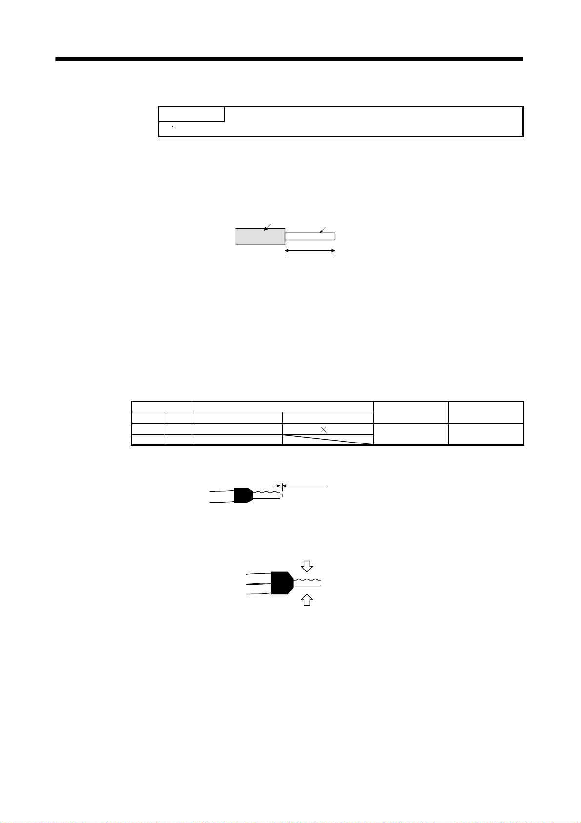
3. SIGNALS AND WIRING
3.11 Servo amplifier terminal block (TE2) wiring method
POINT
Refer to Table 14.1 in section 14.2.1 for the wire sizes used for wiring.
3.11.1 For the servo amplifier produced later than Jan. 2006
(1) Termination of the cables
(a) Solid wire
After the sheath has been stripped, the cable can be used as it is.
Sheath
Approx. 10mm
(b) Twisted wire
1) When the wire is inserted directly
Use the cable after stripping the sheath and twisting the core. At this time, take care to
avoid a short caused by the loose wires of the core and the adjacent pole. Do not solder the
core as it may cause a contact fault. Alternatively, a bar terminal may be used to put the
wires together.
2) When the wires are put together
Using a bar terminal.
Cable Size Bar Terminal Type
[mm2] AWG For 1 cable For 2 cables
1.25/1.5 16 AI1.5-10BK AI-TWIN 1.5-10BK
2/2.5 14 AI2.5-10BU
Cut the wire running out of bar terminal to less than 0.5mm.
Less than 0.5mm
Core
Crimping Tool Manufacturer
CRIMPFOX ZA 3 Phoenix Contact
When using a bar terminal for two wires, insert the wires in the direction where the
insulation sleeve does not interfere with the next pole and pressure them.
Pressure
Pressure
3 - 38
Page 88
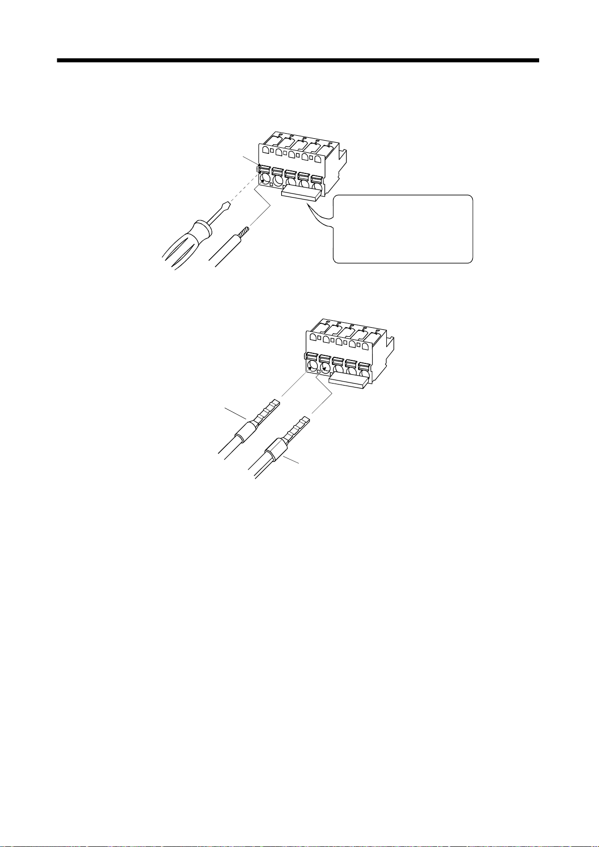
3. SIGNALS AND WIRING
(2) Termination of the cables
(a) When the wire is inserted directly
Insert the wire to the end pressing the button with a small flat blade screwdriver or the like.
Button
Small flat blade
screwdriver or the like
Twisted wire
When removing the short-circuit bar
from across P-D, press the buttons
of P and D alternately pulling the
short-circuit bar. For the installation,
insert the bar straight to the end.
(b) When the wires are put together using a bar terminal
Insert a bar terminal with the odd-shaped side of the pressured terminal on the button side.
Bar terminal for one
wire or solid wire
Bar terminal for two wires
3 - 39
Page 89

3. SIGNALS AND WIRING
3.11.2 For the servo amplifier produced earlier than Dec. 2005
1) Termination of the cables
Solid wire: After the sheath has been stripped, the cable can be used as it is.
Approx. 10mm
(0.39inch)
Twisted wire: Use the cable after stripping the sheath and twisting the core. At this time, take
care to avoid a short caused by the loose wires of the core and the adjacent pole.
Do not solder the core as it may cause a contact fault. Alternatively, a bar
terminal may be used to put the wires together.
Cable size Bar terminal type
[mm2] AWG For 1 cable For 2 cables
1.25/1.5 16
2/2.5 14 AI2.5-10BU
AI1.5-10BK AI-TWIN
2) Connection
Insert the core of the cable into the opening and tighten the screw with a flat-blade screwdriver
so that the cable does not come off. (Tightening torque: 0.3 to 0.4N
inserting the cable into the opening, make sure that the screw of the terminal is fully loose.
When using a cable of 1.5mm
2
or less, two cables may be inserted into one opening.
1.5-10BK
Crimping tool
CRIMPFOX ZA3
or
CRIMPFOX UD 6
Manufacturer
Phoenix Contact
m (2.7 to 3.5Ib in)) Before
3 - 40
Page 90

3. SIGNALS AND WIRING
Flat-blade screwdriver
Tip thickness 0.4 to 0.6mm (0.016 to 0.024in.)
Overall width 2.5 to 3.5mm (0.098 to 0.138in.)
To loosen.
To tighten.
Cable
Opening
Control circuit terminal block
Use of a flat-blade torque screwdriver is recommended to manage the screw tightening torque. The
following table indicates the recommended products of the torque screwdriver for tightening torque
management and the flat-blade bit for torque screwdriver. When managing torque with a Phillips bit,
please consult us.
Product Model Manufacturer/Representative
Torque screwdriver N6L TDK Nakamura Seisakusho
Bit for torque screwdriver B-30, flat-blade, H3.5 X 73L Shiro Sangyo
3 - 41
Page 91

3. SIGNALS AND WIRING
3.12 Instructions for the 3M connector
When fabricating an encoder cable or the like, securely connect the shielded external conductor of the
cable to the ground plate as shown in this section and fix it to the connector shell.
External conductor Sheath
Strip the sheath.
Screw
Cable
Screw
Ground plate
Pull back the external conductor to cover the sheath
External conductor
SheathCore
3 - 42
Page 92

4. OPERATION
4. OPERATION
4.1 When switching power on for the first time
4.1.1 Pre-operation checks
Before starting operation, check the following.
(1) Wiring
(a) A correct power supply is connected to the power input terminals (L
amplifier.
(b) The servo motor power supply terminals (U, V, W) of the servo amplifier match in phase with the
power input terminals (U, V, W) of the servo motor.
(c) The servo motor power supply terminals (U, V, W) of the servo amplifier are not shorted to the
power input terminals (L
(d) The earth terminal of the servo motor is connected to the PE terminal of the servo amplifier.
(e) Note the following when using the regenerative option, brake unit or power regeneration converter.
1) For the MR-J2S-350CP or less, the lead has been removed from across D-P of the control circuit
terminal block, and twisted cables are used for its wiring.
2) For the MR-J2S-500CP or more, the lead has been removed from across P-C of the servo
amplifier built-in regenerative resistor, and twisted cables are used for its wiring.
(f) When stroke end limit switches are used, the signals across LSP-SG and LSN-SG are on during
operation.
(g) 24VDC or higher voltages are not applied to the pins of connectors CN1A and CN1B.
(h) SD and SG of connectors CN1A and CN1B are not shorted.
(i) The wiring cables are free from excessive force.
(2) Environment
Signal cables and power cables are not shorted by wire offcuts, metallic dust or the like.
(3) Machine
(a) The screws in the servo motor installation part and shaft-to-machine connection are tight.
(b) The servo motor and the machine connected with the servo motor can be operated.
1, L2, L3)
of the servo motor.
1, L2, L3, L11, L21) of the servo
4 - 1
Page 93

4. OPERATION
4.1.2 Startup
WARNING
Do not operate the switches with wet hands. You may get an electric shock.
Before starting operation, check the parameters. Some machines may perform
unexpected operation.
Take safety measures, e.g. provide covers, to prevent accidental contact of hands
and parts (cables, etc.) with the servo amplifier heat sink, regenerative resistor,
CAUTION
servo motor, etc.since they may be hot while power is on or for some time after
power-off. Their temperatures may be high and you may get burnt or a parts may
damaged.
During operation, never touch the rotating parts of the servo motor. Doing so can
cause injury.
Connect the servo motor with a machine after confirming that the servo motor operates properly alone.
For startup reference, a single machine structure will be described. Refer to this section and start up the
machine safely.
(1) Machine conditions
P
Servo amplifier
Reduction ratio
1/n 1/2
Ballscrew
10mm(0.39inch)
P
P
B
B
Position data (P) 200mm(787.40inch)
Speed (V) 2500r/min
Acceleration time constant (Ta) 200ms
V
Deceleration time constant (Tb) 300ms
0r/min
HC-MFS131072pulse/rev
Regenerative
option
MR-RB032
Servo motor
Servo motor
speed
Ta
Point table No. 1
Tb
1) Absolute position detection system used
2) Command resolution: 10
m
3) Command system: Absolute value command system
4) Electronic gear calculation
CMX(pulse)
CDV( m)
32768
CMX
1250
CDV
131072 131072
1
n
1000
P
B
1
2
10
1000
131072
5000
32768
1250
........................................................(4.1)
5) For the device command method, external input signals are used by the point table selection,
forward rotation start (ST1), servo-on (SON) and other commands.
6) Point table No.1 is used to execute automatic operation once.
4 - 2
Page 94

4. OPERATION
(2) Startup procedure
(a) Power on
1) Switch off the servo-on (SON).
2) When main circuit power/control circuit power is switched on, "PoS" (Current position) appears
on the servo amplifier display.
In the absolute position detection system, first power-on results in the absolute position lost
(AL.25) alarm and the servo system cannot be switched on. This is not a failure and takes place
due to the uncharged capacitor in the encoder.
The alarm can be deactivated by keeping power on for a few minutes in the alarm status and
then switching power off once and on again.
Also in the absolute position detection system, if power is switched on at the servo motor speed
of 500r/min or higher, position mismatch may occur due to external force or the like. Power must
therefore be switched on when the servo motor is at a stop.
(b) Test operation
Using jog operation in the "test operation mode" of the MR Configurator (servo configuration
software), confirm that the servo motor operates at the slowest speed. (Refer to section 6.7.1, 7.9.2)
(c) Parameter setting
Set the parameters according to the structure and specifications of the machine. Refer to chapter 5
for the parameter definitions and to sections 6.4 and 7.6 for the setting method.
Parameter Name Setting Description
No.0
Command system, regenerative
option selection
20
Absolute value command system.
MR-RB032 regenerative option is used.
No.1 Feeding function selection
No.2 Function selection 1
No.4 Electronic gear numerator (CMX)
No.5 Electronic gear denominator (CDV)
After setting the above parameters, switch power off once. Then switch power on again to make the
set parameter values valid.
(d) Point table setting
Set the point table according to the operation pattern. Refer to section 4.2 for the point table
definitions and to sections 6.5 and 7.5 for the setting method.
Position data
STM
[
10
m]
20000 2500 200 300 0 0
(e) Servo-on
Switch the servo-on in the following procedure.
1) Switch on main circuit/control circuit power.
2) Switch on the servo-on (SON).
When placed in the servo-on status, the servo amplifier is ready to operate and the servo motor is
locked. By using the sequence in the diagnostic mode in section 7.3, the ready status can be shown
on the servo amplifier display. In the operation-ready status, the following screen appears.
Servo motor
speed[r/min]
1
32768 From calculation result of formula (4.1)
1250 From calculation result of formula (4.1)
Acceleration time
constant[ms]
10
When forward rotation start (ST1) is
valid, address is incremented in CCW
direction.
Since command resolution is 10 times,
feed length multiplication factor of 10
times is selected.
Absolute position detection system.
Deceleration time
constant[ms]
Dwell [ms]
Auxiliary
function
4 - 3
Page 95

4. OPERATION
(f) Home position return
Perform home position return as required. Refer to section 4.4 for home position return types. A
parameter setting example for dog type home position return is given here.
Parameter Name Setting Description
No.8 Home position return type
No.9 Home position return speed 1000 Motion is made up to proximity dog at 1000r/min.
No.10 Creep speed 10 Motion is made up to home position at 10r/min.
No.11 Home position shift distance 0 No home position shift
No.42 Home position return position data
No.43 Moving distance after proximity dog Not used in dog type home position return.
After setting the above parameters, switch power off once. Then switch power on again to make the
set parameter values valid.
Set the input signals as listed below and switch on the forward rotation start (ST1) to execute
home position return.
Device name Symbol ON/OFF Description
Automatic/manual selection MD0 ON
Point table No. selection 1 DI0 OFF
Point table No. selection 2 DI1 OFF
Forward rotation stroke end LSP ON CCW rotation side limit switch is turned on.
Reverse rotation stroke end LSN ON CW rotation side limit switch is turned on.
Servo-on SON ON Servo is switched on.
(g) Automatic operation
Set the input signals as listed below and switch on the forward rotation start (ST1) to execute
automatic operation in accordance with point table No.1.
Device name Symbol ON/OFF Description
Automatic/manual selection MD0 ON Automatic operation mode is selected.
Servo-on SON ON Servo is switched on.
Forward rotation stroke end LSP ON CCW rotation side limit switch is turned on.
Reverse rotation stroke end LSN ON CW rotation side limit switch is turned on.
Point table No. selection 1 DI0 ON
Point table No. selection 2 DI1 OFF
(h) Stop
In any of the following statuses, the servo amplifier interrupts and stops the operation of the servo
motor.
When the servo motor used is equipped with an electromagnetic brake, refer to section 3.9 (3). Note
that forward rotation stroke end (LSP), reverse rotation stroke end (LSN) off has the same
stopping pattern as described below.
1) Servo-on (SON) OFF
The base circuit is shut off and the servo motor coasts.
2) Alarm occurrence
When an alarm occurs, the base circuit is shut off and the dynamic brake is operated to bring the
servo motor to a sudden stop.
3) Forced stop (EMG) OFF
The base circuit is shut off and the dynamic brake is operated to bring the servo motor to a
sudden stop. Servo forced warning (AL.E6) occurs.
4) Forward rotation stroke end (LSP), reverse rotation stroke end (LSN) OFF
The droop pulse value is erased and the servo motor is stopped and servo-locked. It can be run in
the opposite direction.
000
Dog type home position return is selected.
Home position return is started in address
incremented direction.
Proximity dog (DOG) is valid when DOGSG are opened.
Use to set the current position on completion of home
position return.
Home position return mode is selected.
Point table No.1 is selected.
4 - 4
Page 96

4. OPERATION
4.2 Automatic operation mode
4.2.1 What is automatic operation mode?
(1) Command system
After selection of preset point tables using the input signals or communication, operation is started by
the forward rotation start (ST1) or reverse rotation start (ST2). Automatic operation has the absolute
value command system, incremental value command system and absolute value
command/incremental value command specifying system.
(a) Absolute value command system
As position data, set the target address to be reached.
Setting range:
999999
999999 to 999999 [ 10
STM
m] (STM feed length multiplication parameter No.1)
999999
Position data setting range
STM
[ 10 m]
(b) Incremental value command system
As position data, set the moving distance from the current address to the target address.
Setting range: 0 to 999999 [
Current address
Position data |target address - current address|
STM
10
m] (STM feed length multiplication parameter No.1)
Target address
(c) Absolute value command/incremental value command specifying system
You can set the absolute value address or incremental value address to each point table as position
data. After the axis has been positioned at the target address, it can be moved a given distance.
4 - 5
Page 97

4. OPERATION
(2) Point table
(a) Point table setting
Up to 15 point tables may be set. To use point table No.s 4 to 31, however, the point table No.
selection 3 (DI2), point table No. selection 4 (DI3) and point table No. selection 5 (DI4) should be
made valid in "I/O Devices" on the MR Configurator (servo configuration software).
Set the point tables using the MR Configurator (servo configuration software) or the servo
amplifier operation section.
The following table lists what to set. Refer to section 4.2.2, section 4.2.3 and section 4.2.4 for details
of the settings.
Name Description
Position data Set the position data for movement.
Servo motor speed Set the command speed of the servo motor for execution of positioning.
Acceleration time constant Set the acceleration time constant.
Deceleration time constant Set the deceleration time constant.
Dwell Set the waiting time when performing automatic continuous operation.
Auxiliary function Set when performing automatic continuous operation.
(b) Selection of point table
Using the input signal or communication function, select the point table No. with a command from
the command device (controller) such as a personal computer.
The following table lists the point table No. selected in response to the input signals/commands.
Note that when the input signals are used, the point tables used as standard are No.1 to 3. To use
No.4 to 31, the point table No. selection 3 (DI2), point table No. selection 4 (DI3) and point table
No. selection 5 (DI4) should be made valid in "I/O Devices" (Refer to chapter 6) on the MR
Configurator (servo configuration software).
When the communication function is used to select the point tables, refer to chapter 15 for details
of the command transmission method, etc.
4 - 6
Page 98

4. OPERATION
(Note 1) DI4 (Note 1) DI3 (Note 1) DI2 DI1 DI0
0 0 0 0 0 0 (Manual home position return mode)
0 0 0 0 1 1
0 0 0 1 0 2
0 0 0 1 1 3
0 0 1 0 0 4
0 0 1 0 1 5
0 0 1 1 0 6
0 0 1 1 1 7
0 1 0 0 0 8
0 1 0 0 1 9
0 1 0 1 0 10
0 1 0 1 1 11
0 1 1 0 0 12
0 1 1 0 1 13
0 1 1 1 0 14
0 1 1 1 1 15
1 0 0 0 0 16
1 0 0 0 1 17
1 0 0 1 0 18
1 0 0 1 1 19
1 0 1 0 0 20
1 0 1 0 1 21
1 0 1 1 0 22
1 0 1 1 1 23
1 1 0 0 0 24
1 1 0 0 1 25
1 1 0 1 0 26
1 1 0 1 1 27
1 1 1 0 0 28
1 1 1 0 1 29
1 1 1 1 0 30
1 1 1 1 1 31
Note 1. Make signals valid in "I/O Devices" on the MR Configurator (servo configuration software).
2. "1": short
"0": open
(Note 2) Input signals
Selected point table No.
4 - 7
Page 99

4. OPERATION
4.2.2 Absolute value command system
(1) Point table
Set the point table values using the MR Configurator (servo configuration software) or from the
operating section.
Set the position data, motor speed, acceleration time constant, deceleration time constant, dwell and
auxiliary function to the point table. The following table gives a setting example.
Name Setting range Unit Description
Set the target address (absolute value).
Position data 999999 to 999999 [ 10
Motor speed 0 to permissible speed r/min
Acceleration
time constant
Deceleration
time constant
Dwell 0 to 20000 ms
Auxiliary
function
0 to 20000 ms
0 to 20000 ms
0
1
STM
This value can also be set using the teaching function. (Refer to section
7.10.)
m]
The unit can be changed using feed length multiplication factor selection of
parameter No. 1.
Set the command speed of the servo motor for execution of positioning.
The setting should be equal to or less than the instantaneous permissible
speed of the servo motor.
Set the acceleration time constant.
Set the time until the rated speed of the servo motor is reached.
Set the deceleration time constant.
Set the time until the servo motor running at rated speed comes to a stop.
Set the dwell.
Set "0" in the auxiliary function to make the dwell invalid.
Set "1" in the auxiliary function and 0 in the dwell to perform continuous
operation.
When the dwell is set, the position command of the selected point table is
completed, and after the set dwell has elapsed, the position command of the
next point table is started.
Set the auxiliary function.
0: Automatic operation is performed in accordance with a single point table
chosen.
1: Operation is performed in accordance with consecutive point tables
without a stop.
When a different rotation direction is set, smoothing zero (command
output) is confirmed and the rotation direction is then reversed.
Setting "1" in point table No.31 results in an error.
For full information, refer to section 4.2.6.
(2) Parameter setting
Set the following parameters to perform automatic operation.
(a) Command mode selection (parameter No.0)
Select the absolute value command system.
Parameter No. 0
0
Absolute value command system
4 - 8
Page 100

4. OPERATION
(b) ST1 coordinate system selection (parameter No.1)
Choose the servo motor rotation direction at the time when the forward rotation start (ST1) is
switched on.
Parameter No. 1 setting
0
1
when forward rotation start (ST1) is switched on
CCW rotation with
CW rotation with
CW rotation with
CCW rotation with
Servo motor rotation direction
CCW
position data
position data
position data
position data
CW
(c) Feed length multiplication selection (parameter No.1)
Set the unit multiplication factor (STM) of position data.
Parameter No.1 setting Position data input range [mm]
0 999.999 to 999.999
1 9999.99 to 9999.99
2 99999.9 to 99999.9
3 999999 to 999999
(3) Operation
Choose the point table using DI0 to DI4 and short ST1-SG to perform positioning to the position data
under the conditions of the preset speed, acceleration time constant and deceleration time constant. At
this time, reverse rotation start (ST2) is invalid.
Item Setting method Description
Automatic operation mode selection Automatic/manual selection (MD0) MD0 is turned on.
Point table No. selection 1 (DI0)
Point table No. selection 2 (DI1)
Point table selection
Start Forward rotation start (ST1) Short ST1-SG (ON) to start.
Point table No. selection 3 (DI2)
Point table No. selection 4 (DI3)
Point table No. selection 5 (DI4)
Refer to section 4.2.1, (2).
4 - 9
 Loading...