


General-Purpose AC Servo
J2-Super Series
J2-Super Series MR-J2S- B-PY096 MR-J2S- B-S096(5.7kW) Instruction Manual
SSCNET Fully Closed Control Compatible
MODEL
MR-J2S- B-PY096
MR-J2S- B-S096(5.7kW)
INSTRUCTION MANUAL
B
B
A - 1
Safety Instructions
(Always read these instructions before using the equipment.)
Do not attempt to install, operate, maintain or inspect the servo amplifier and servo motor until you have read
through this Instruction Manual, Installation guide, Servo motor Instruction Manual and appended documents
carefully and can use the equipment correctly. Do not use the servo amplifier and servo motor until you have a
full knowledge of the equipment, safety information and instructions.
In this Instruction Manual, the safety instruction levels are classified into "WARNING" and "CAUTION".
WARNING
Indicates that incorrect handling may cause hazardous conditions,
resulting in death or severe injury.
CAUTION
Indicates that incorrect handling may cause hazardous conditions,
resulting in medium or slight injury to personnel or may cause physical
damage.
Note that the CAUTION level may lead to a serious consequence according to conditions. Please follow the
instructions of both levels because they are important to personnel safety.
What must not be done and what must be done are indicated by the following diagrammatic symbols:
: Indicates what must not be done. For example, "No Fire" is indicated by
.
: Indicates what must be done. For example, grounding is indicated by
.
In this Instruction Manual, instructions at a lower level than the above, instructions for other functions, and so
on are classified into "POINT".
After reading this Instruction Manual, always keep it accessible to the operator.
A - 2
1. To prevent electric shock, note the following:
WARNING
Before wiring or inspection, switch power off and wait for more than 15 minutes. Then, confirm the voltage
is safe with voltage tester. Otherwise, you may get an electric shock.
Connect the servo amplifier and servo motor to ground.
Any person who is involved in wiring and inspection should be fully competent to do the work.
Do not attempt to wire the servo amplifier and servo motor until they have been installed. Otherwise, you
may get an electric shock.
Operate the switches with dry hand to prevent an electric shock.
The cables should not be damaged, stressed, loaded, or pinched. Otherwise, you may get an electric shock.
During power-on or operation, do not open the front cover. You may get an electric shock.
Do not operate the converter unit and servo amplifier with the front cover removed. High-voltage terminals
and charging area are exposed and you may get an electric shock.
Except for wiring or periodic inspection, do not remove the front cover even if the power is off. The servo
amplifier is charged and you may get an electric shock.
2. To prevent fire, note the following:
CAUTION
Install the converter unit and servo amplifier, servo motor and regenerative resistor on incombustible
material. Installing them directly or close to combustibles will lead to a fire.
When the servo amplifier has become faulty, switch off the main servo amplifier power side. Continuous
flow of a large current may cause a fire.
When a regenerative resistor is used, use an alarm signal to switch main power off. Otherwise, a
regenerative transistor fault or the like may overheat the regenerative resistor, causing a fire.
3. To prevent injury, note the follow
CAUTION
Only the voltage specified in the Instruction Manual should be applied to each terminal. Otherwise, a burst,
damage, etc. may occur.
Connect the terminals correctly to prevent a burst, damage, etc.
Ensure that polarity ( , ) is correct. Otherwise, a burst, damage, etc. may occur.
During power-on or for some time after power-off, do not touch or close a parts (cable etc.) to the servo
amplifier heat sink, regenerative resistor, servo motor, etc. Their temperatures may be high and you may
get burnt or a parts may damaged.
During operation, never touch the rotating parts of the servo motor. Doing so can cause injury.
A - 3
4. Additional instructions
The following instructions should also be fully noted. Incorrect handling may cause a fault, injury, electric
shock, etc.
(1) Transportation and installation
CAUTION
Transport the products correctly according to their weights.
Stacking in excess of the specified number of products is not allowed.
Do not carry the servo motor by the cables, shaft or encoder.
Do not hold the front cover to transport the controller. The controller may drop.
Install the servo amplifier in a load-bearing place in accordance with the Instruction Manual.
Do not climb or stand on servo equipment. Do not put heavy objects on equipment.
The controller and servo motor must be installed in the specified direction.
Leave specified clearances between the servo amplifier and control enclosure walls or other equipment.
Do not install or operate the servo amplifier and servo motor which has been damaged or has any parts
missing.
Provide adequate protection to prevent screws and other conductive matter, oil and other combustible
matter from entering the servo amplifier and servo motor.
Do not drop or strike servo amplifier or servo motor. Isolate from all impact loads.
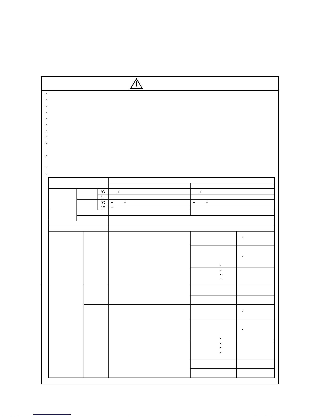
When you keep or use it, please fulfill the following environmental conditions.
Conditions
Environment
Servo amplifier Servo motor
[ ] 0 to 55 (non-freezing) 0 to 40 (non-freezing)
Operation
[
] 32 to 131 (non-freezing) 32 to 104 (non-freezing)
[ ] 20 to 65 (non-freezing) 15 to 70 (non-freezing)
Ambient
temperature
Storage
[
] 4 to 149 (non-freezing) 5 to 158 (non-freezing)
Operation 90%RH or less (non-condensing) 80%RH or less (non-condensing)
Ambient
humidity
Storage 90%RH or less (non-condensing)
Ambience Indoors (no direct sunlight) Free from corrosive gas, flammable gas, oil mist, dust and dirt
Altitude Max. 1000m (3280 ft) above sea level
HC-KFS Series
HC-MFS Series
HC-UFS13 to 73
X
Y : 49
HC-SFS81
HC-SFS52 to 152
HC-SFS53 to 153
HC-RFS Series
HC-UFS 72
152
X
Y : 24.5
HC-SFS121 201
HC-SFS202
352
HC-SFS203
353
HC-UFS202 to 502
X : 24.5
Y : 49
HC-SFS301
HC-SFS502 to 702
X : 24.5
Y : 29.4
[m/s2] 5.9 or less
HA-LFS11K2 to 22K2
X : 11.7
Y : 29.4
HC-KFS Series
HC-MFS Series
HC-UFS 13 to 73
X
Y : 161
HC-SFS81
HC-SFS52 to 152
HC-SFS53 to 153
HC-RFS Series
HC-UFS 72 152
X
Y : 80
HC-SFS121 201
HC-SFS202
352
HC-SFS203
353
HC-UFS202 to 502
X : 80
Y : 161
HC-SFS301
HC-SFS502 to 702
X : 80
Y : 96
(Note)
Vibration
[ft/s
2
] 19.4 or less
HA-LFS11K2 to 22K2
X : 38
Y : 96
Note. Except the servo motor with reduction gear.
A - 4
CAUTION
Securely attach the servo motor to the machine. If attach insecurely, the servo motor may come off during
operation.
The servo motor with reduction gear must be installed in the specified direction to prevent oil leakage.
Take safety measures, e.g. provide covers, to prevent accidental access to the rotating parts of the servo
motor during operation.
Never hit the servo motor or shaft, especially when coupling the servo motor to the machine. The encoder
may become faulty.
Do not subject the servo motor shaft to more than the permissible load. Otherwise, the shaft may break.
When the equipment has been stored for an extended period of time, consult Mitsubishi.
(2) Wiring
CAUTION
Wire the equipment correctly and securely. Otherwise, the servo motor may misoperate.
Do not install a power capacitor, surge absorber or radio noise filter (FR-BIF option) between the servo
motor and servo amplifier.
Connect the output terminals (U, V, W) correctly. Otherwise, the servo motor will operate improperly.
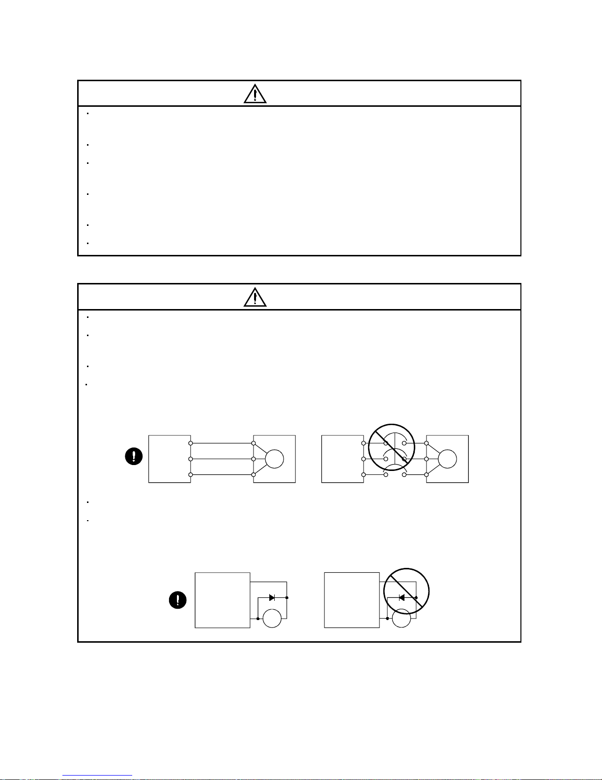
Connect the servo motor power terminal (U, V, W) to the servo motor power input terminal (U, V, W)
directly. Do not let a magnetic contactor, etc. intervene.
U
Servo Motor
M
V
W
U
V
W
U
M
V
W
U
V
W
Servo Amplifier
(drive unit)
Servo Motor
Servo Amplifier
(drive unit)
Do not connect AC power directly to the servo motor. Otherwise, a fault may occur.
The surge absorbing diode installed on the DC output signal of the servo amplifier relay must be wired in
the specified direction. Otherwise, the forced stop (EM1) and other protective circuits may not operate.
COM
(24VDC)
Servo
Amplifier
RA
Control
output
signal
RA
Servo
Amplifier
COM
(24VDC)
Control
output
signal

A - 5
(3) Test run adjustment
CAUTION
Before operation, check the parameter settings. Improper settings may cause some machines to perform
unexpected operation.
The parameter settings must not be changed excessively. Operation will be insatiable.
(4) Usage
CAUTION
Provide a forced stop circuit to ensure that operation can be stopped and power switched off immediately.
Any person who is involved in disassembly and repair should be fully competent to do the work.
Before resetting an alarm, make sure that the run signal of the servo amplifier is off to prevent an
accident. A sudden restart is made if an alarm is reset with the run signal on.
Do not modify the equipment.
Use a noise filter, etc. to minimize the influence of electromagnetic interference, which may be caused by
electronic equipment used near the servo amplifier.
Burning or breaking a servo amplifier may cause a toxic gas. Do not burn or break a servo amplifier.
Use the servo amplifier with the specified servo motor.
The electromagnetic brake on the servo motor is designed to hold the motor shaft and should not be used
for ordinary braking.
For such reasons as service life and mechanical structure (e.g. where a ballscrew and the servo motor
are coupled via a timing belt), the electromagnetic brake may not hold the motor shaft. To ensure safety,
install a stopper on the machine side.
(5) Corrective actions
CAUTION
When it is assumed that a hazardous condition may take place at the occur due to a power failure or a
product fault, use a servo motor with electromagnetic brake or an external brake mechanism for the
purpose of prevention.
Configure the electromagnetic brake circuit so that it is activated not only by the interface unit signals but
also by a forced stop (EM1).
EM1RA
24VDC
Contacts must be open when
servo-off, when an alarm occurrence
and when an electromagnetic brake
interlock (MBR).
Electromagnetic brake
Servo motor
Circuit must be
opened during
forced stop (EM1).
A - 6
CAUTION
When any alarm has occurred, eliminate its cause, ensure safety, and deactivate the alarm before
restarting operation.
When power is restored after an instantaneous power failure, keep away from the machine because the
machine may be restarted suddenly (design the machine so that it is secured against hazard if restarted).
(6) Maintenance, inspection and parts replacement
CAUTION
With age, the electrolytic capacitor of the servo amplifier will deteriorate. To prevent a secondary accident
due to a fault, it is recommended to replace the electrolytic capacitor every 10 years when used in general
environment. Please consult our sales representative.
(7) General instruction
To illustrate details, the equipment in the diagrams of this Instruction Manual may have been drawn
without covers and safety guards. When the equipment is operated, the covers and safety guards must
be installed as specified. Operation must be performed in accordance with this Instruction Manual.
About processing of waste
When you discard servo amplifier, a battery (primary battery), and other option articles, please follow the law of
each country (area).
FOR MAXIMUM SAFETY
These products have been manufactured as a general-purpose part for general industries, and have not
been designed or manufactured to be incorporated in a device or system used in purposes related to
human life.
Before using the products for special purposes such as nuclear power, electric power, aerospace,
medicine, passenger movement vehicles or under water relays, contact Mitsubishi.
These products have been manufactured under strict quality control. However, when installing the product
where major accidents or losses could occur if the product fails, install appropriate backup or failsafe
functions in the system.
EEP-ROM life
The number of write times to the EEP-ROM, which stores parameter settings, etc., is limited to 100,000. If
the total number of the following operations exceeds 100,000, the servo amplifier and/or converter unit may
fail when the EEP-ROM reaches the end of its useful life.
Write to the EEP-ROM due to parameter setting changes
Precautions for Choosing the Products
Mitsubishi will not be held liable for damage caused by factors found not to be the cause of Mitsubishi;
machine damage or lost profits caused by faults in the Mitsubishi products; damage, secondary damage,
accident compensation caused by special factors unpredictable by Mitsubishi; damages to products other
than Mitsubishi products; and to other duties.
A - 7
COMPLIANCE WITH EC DIRECTIVES
1. WHAT ARE EC DIRECTIVES?
The EC directives were issued to standardize the regulations of the EU countries and ensure smooth
distribution of safety-guaranteed products. In the EU countries, the machinery directive (effective in
January, 1995), EMC directive (effective in January, 1996) and low voltage directive (effective in January,
1997) of the EC directives require that products to be sold should meet their fundamental safety
requirements and carry the CE marks (CE marking). CE marking applies to machines and equipment
into which servo amplifiers have been installed.
(1) EMC directive
The EMC directive applies not to the servo units alone but to servo-incorporated machines and
equipment. This requires the EMC filters to be used with the servo-incorporated machines and
equipment to comply with the EMC directive. For specific EMC directive conforming methods, refer to
the EMC Installation Guidelines (IB(NA)67310).
(2) Low voltage directive
The low voltage directive applies also to servo units alone. Hence, they are designed to comply with
the low voltage directive.
This servo is certified by TUV, third-party assessment organization, to comply with the low voltage
directive.
(3) Machine directive
Not being machines, the servo amplifiers need not comply with this directive.
2. PRECAUTIONS FOR COMPLIANCE
(1) Servo amplifiers and servo motors used
Use the servo amplifiers and servo motors which comply with the standard model.
Servo amplifier :MR-J2S-10B-PY096 to MR-J2S-350B-PY096
MR-J2S-500B-S096 to MR-J2S-700B-S096
MR-J2S-10B1-PY096 to MR-J2S-40B1-PY096
Servo motor :HC-KFS
HC-MFS
HC-SFS
HC-RFS
HC-UFS
HA-LFS
HC-LFS
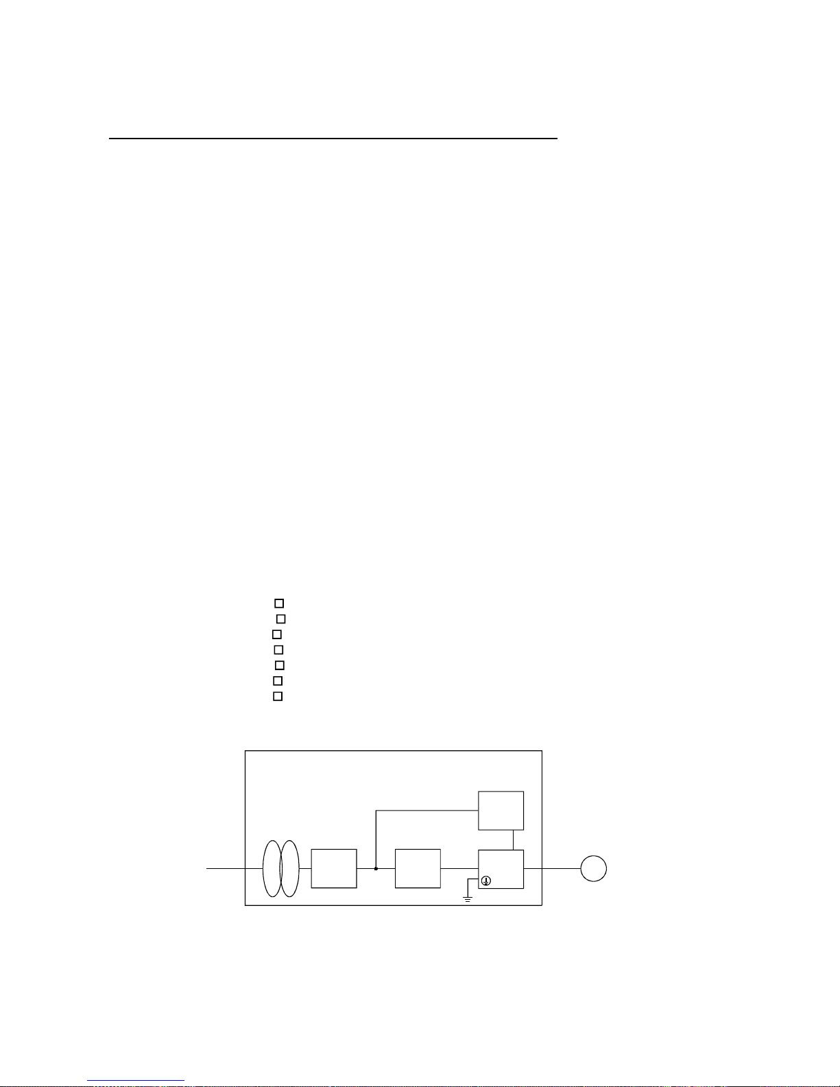
(2) Configuration
Reinforced
insulating
transformer
NFB
MC
SM
No-fuse
breaker
Magnetic
contactor
Reinforced
insulating type
24VDC
power
supply
Servo
amplifier
Servo
motor
Control box
(Note)
Note. The insulating transformer is not required for the 11kW or more servo amplifier.
(3) Environment
Operate the servo amplifier at or above the contamination level 2 set forth in IEC664. For this
purpose, install the servo amplifier in a control box which is protected against water, oil, carbon, dust,
dirt, etc. (IP54).
A - 8
(4) Power supply
(a) Operate the servo amplifier 7kW or less to meet the requirements of the overvoltage category II set
forth in IEC664. For this purpose, a reinforced insulating transformer conforming to the IEC or EN
standard should be used in the power input section.
Since the 11kW or more servo amplifier can be used under the conditions of the overvoltage
category III set forth in IE644, a reinforced insulating transformer is not required in the power
input section.
(b) When supplying interface power from external, use a 24VDC power supply which has been
insulation-reinforced in I/O.
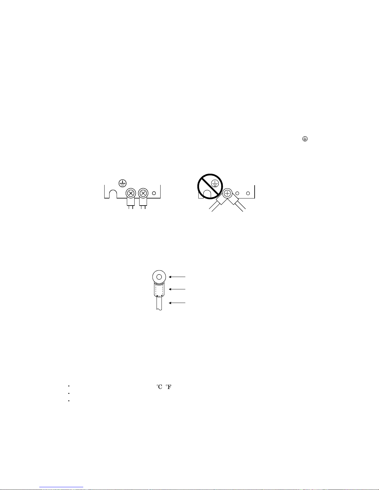
(5) Grounding
(a) To prevent an electric shock, always connect the protective earth (PE) terminals (marked
) of the
servo amplifier to the protective earth (PE) of the control box.
(b) Do not connect two ground cables to the same protective earth (PE) terminal Always connect the
cables to the terminals one-to-one.
PE terminals
PE terminals
(c) If a leakage current breaker is used to prevent an electric shock, the protective earth (PE)
terminals of the servo amplifier must be connected to the corresponding earth terminals.
(6) Wiring
(a) The cables to be connected to the terminal block of the servo amplifier must have crimping
terminals provided with insulating tubes to prevent contact with adjacent terminals.
Crimping terminal
Insulating tube
Cable
(b) Use the servo motor side power connector which complies with the EN Standard. The EN Standard
compliant power connector sets are available from us as options.
(7) Auxiliary equipment and options
(a) The no-fuse breaker and magnetic contactor used should be the EN or IEC standard-compliant
products of the models described in Section 12.2.2.
(b) The sizes of the cables described in Section 12.2.1 meet the following requirements. To meet the
other requirements, follow Table 5 and Appendix C in EN60204-1.
Ambient temperature: 40 (104) [ ( )]
Sheath: PVC (polyvinyl chloride)
Installed on wall surface or open table tray
(c) Use the EMC filter for noise reduction.
A - 9
(8) Performing EMC tests
When EMC tests are run on a machine/device into which the servo amplifier has been installed, it
must conform to the electromagnetic compatibility (immunity/emission) standards after it has
satisfied the operating environment/electrical equipment specifications.
For the other EMC directive guidelines on the servo amplifier, refer to the EMC Installation
Guidelines(IB(NA)67310).
CONFORMANCE WITH UL/C-UL STANDARD
(1) Servo amplifiers and servo motors used
Use the servo amplifiers and servo motors which comply with the standard model.
Servo amplifier :MR-J2S-10B-PY096 to MR-J2S-350B-PY096
MR-J2S-500B-S096 to MR-J2S-700B-S096
MR-J2S-10B1-PY096 to MR-J2S-40B1-PY096
Servo motor :HC-KFS
HC-MFS
HC-SFS
HC-RFS
HC-UFS
HA-LFS
HC-LFS
(2) Installation
Install a cooling fan of 100CFM (2.8m
3
/min) air flow 4 in (10.16 cm) above the servo amplifier or
provide cooling of at least equivalent capability.
(3) Short circuit rating
This servo amplifier conforms to the circuit whose peak current is limited to 5000A or less. Having
been subjected to the short-circuit tests of the UL in the alternating-current circuit, the servo
amplifier conforms to the above circuit.
(4) Capacitor discharge time
The capacitor discharge time is as listed below. To ensure safety, do not touch the charging section for
15 minutes after power-off.
Servo amplifier
Discharge time
[min]
MR-J2S-10B(1) 20B(1) 1
MR-J2S-40B(1) 60B 2
MR-J2S-70B to 350B 3
MR-J2S-500B 700B 5
MR-J2S-11KB 4
MR-J2S-15KB 6
MR-J2S-22KB 8
(5) Options and auxiliary equipment
Use UL/C-UL standard-compliant products.

A - 10
(6) Attachment of a servo motor
For the flange size of the machine side where the servo motor is installed, refer to "CONFORMANCE
WITH UL/C-UL STANDARD" in the Servo Motor Instruction Manual.
(7) About wiring protection
For installation in United States, branch circuit protection must be provided, in accordance with the
National Electrical Code and any applicable local codes.
For installation in Canada, branch circuit protection must be provided, in accordance with the Canada
Electrical Code and any applicable provincial codes.

1
CONTENTS
1. FUNCTIONS AND CONFIGURATION 1- 1 to 1- 6
1.1 Overview................................................................................................................................................... 1- 1
1.2 Control block diagram............................................................................................................................. 1- 2
1.3 Specification list....................................................................................................................................... 1- 3
1.4 Model name .............................................................................................................................................. 1- 3
1.5 System configuration............................................................................................................................... 1- 4
2. LINEAR SCALES 2- 1 to 2-30
2.1 Compatible linear scale list .................................................................................................................... 2- 1
2.1.1 Mitutoyo make linear scales (ABS type) ........................................................................................2- 2
2.1.2 Heidenhain make linear encoder (linear scale) (ABS type) ......................................................... 2- 9
2.1.3 Renishaw make linear encoders (linear scales) (INC type)......................................................... 2-15
2.1.4 Sony precision technology make linear encoders (linear scales) (INC type) .............................2-21
2.2 A
B Z-phase differential input Interface unit specifications.......................................................... 2-27
3. SIGNALS AND WIRING 3- 1 to 3- 6
3.1 Standard connection examples of full closed control servo amplifier control signals....................... 3- 1
3.2 Signal
t
erminal explanation ................................................................................................................. 3- 5
3.3 About power-on ........................................................................................................................................ 3- 6
4. OPERATION AND FUNCTIONS 4- 1 to 4-22
4.1 Startup...................................................................................................................................................... 4- 1
4.1.1 Startup procedure............................................................................................................................. 4- 1
4.1.2 Selection of full closed function ....................................................................................................... 4- 2
4.1.3 Selection of full closed encoder communication system................................................................ 4- 3
4.1.4 Setting of full closed encoder polarity............................................................................................. 4- 4
4.1.5 Setting of full closed encoder electronic gear ................................................................................. 4- 5
4.1.6 Confirmation of full closed encoder position data .........................................................................4- 6
4.1.7 Setting of dual feedback switching filter ........................................................................................ 4- 7
4.2 Home position return operation .............................................................................................................4- 8
4.2.1 General precautions ......................................................................................................................... 4- 8
4.2.2 Full closed encoder types and home position return methods ..................................................... 4- 8
4.3 Operation from controller ...................................................................................................................... 4-15
4.3.1 Operation from controller ...............................................................................................................4-15
4.3.2 Controller setting............................................................................................................................. 4-15
4.4 Functions .................................................................................................................................................4-17
4.4.1 Full closed control error detection.................................................................................................. 4-17
4.4.2 Auto tuning function ....................................................................................................................... 4-18
4.4.3 Machine analyzer function ............................................................................................................. 4-18
4.4.4 Test operation .................................................................................................................................. 4-18
4.5 Absolute position detection system....................................................................................................... 4-19

2
4.6 About the MR Configurator ................................................................................................................... 4-20
4.6.1 When current version of MR Configurator
(MRZJW3-SETUP121 to -SETUP151 S/W: E0 version) is used ................................................. 4-20
4.6.2 When full closed compatible MR Configurator
(MRZJW3-SETUP151 S/W: E1 version or later) is used .............................................................4-21
5. PARAMETERS 5- 1 to 5- 8
5.1 Parameter list ...................................................................................................................................... 5- 1
6. TROUBLESHOOTING 6- 1 to 6- 2
6.1 Alarm list.................................................................................................................................................. 6- 1
6.2 Scale error (AL. 2A) details classified by linear scale manufacturer .................................................6- 2
7. OPTIONS AND AUXILIARY EQUIPMENT 7- 1 to 7- 2
7.1 CN2 wiring option cable (MR-J2SCLCBL02M-P-H) ........................................................................... 7- 1

1 - 1
1. FUNCTIONS AND CONFIGURATION
1 FUNCTIONS AND CONFIGURATION
1.1 Overview
This Instruction Manual explains the product that imports a position F/B signal from a full closed
encoder, such as a linear scale, to the MR-J2S-B servo amplifier to perform full closed control.
For the items not described in this Instruction Manual, refer to the MELSERVO-J2S-B Specifications and
Installation Guide and Instruction Manual since they are the same as those of the standard model.
For the specifications of the A
B Z differential input I/F unit MR-J2S-CLP01, refer to the MR-J2S-
CLP01 Installation Guide.
[Items changed from those of the standard model]
1) The A
B Z differential input I/F unit MR-J2S-CLP01 or Mitsubishi serial interface compatible
linear scale is used to detect the position F/B signal of a full closed encoder such as a linear scale.
2) In addition to the full closed control that feeds back the position signal of the full closed encoder,
dual F/B control that feeds back a signal composed of the full closed encoder's position F/B signal
and the motor position F/B signal has been added as an extended function.
3) Function to switch pulse output between the full closed encoder and motor end encoder
4) Addition of restriction on the RS232C communication baud rate (enabled for 9600bps only)
[Functions deleted from the standard model]
1) Speed
torque control
2) Motor-less operation (test operation)
1 - 2
1. FUNCTIONS AND CONFIGURATION
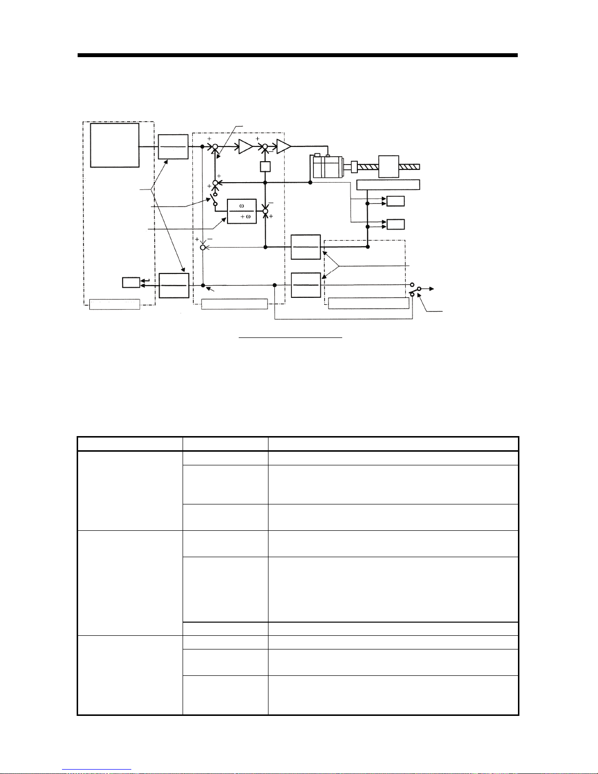
1.2 Control block diagram
A full closed control block diagram is shown below.
Controller
Command pulse
train electronic gear
Parameter No. 6
Full closed selection
Parameter No. 62
(Note 1, 2)
Dual F/B filter
Parameter No. 67
(Note 2)
In-position judgment
INP
Command pulse uni t
1
CMX
CMX
1
S
Dual f/b position signal
Position deviation
Encoder pulse unit
FCM
FCD
FCD
FCM
Servo motor
Linear scale
OP9
FCT
Closed end pulse unit
ABZ phase pulse
output selection
Parameter No. 68
Full closed control error
detection function selection
Parameter No. 62, 63, 64
Full closed electronic gear
Parameter No. 65, 66
Droop pulses (MR Configurator
display, analog monitor)
Droop pulse unit
selection
Parameter No. 68
Full closed control block diagram
S
Note 1. Switching between semi closed control and full closed control can be performed by changing the setting of parameter No. 62.
When semi closed control is selected, control is always performed on the basis of the position data of the motor end encoder
(independently of whether the motor is at a stop or running).
2. When parameter No. 62 "full closed function" is valid, dual F/B control in which the motor F/B signal and full closed encoder F/B
signal are combined by the dual F/B filter in parameter No. 67 is performed.
In this case, full closed control is performed when the motor is at a stop, and semi closed control is performed when the motor
is operating to improve control performance. When 1000 is set as the filter value of parameter No. 67, full closed control is
always performed.
Control Mode Item Description
Feature Position is controlled according to the motor end data.
Advantage
Since this control is insusceptible to machine influence (such as
machine resonance), the gains of the servo amplifier can be
raised and the settling time shortened.
Semi closed control
Disadvantage
If the motor end is at a stop, the machine end may be vibrating
or the machine end accuracy not obtained.
Feature
Position is controlled according to the motor end data and
machine end data.
Advantage
Control is performed according to the motor end data during
operation, and according to the machine end data at a stop in
sequence to raise the gains during operation and shorten the
settling time.
A stop is made with the machine end accuracy.
Dual F/B control
Disadvantage No specific disadvantage.
Feature Position is controlled according to the machine end data.
Advantage
The machine end accuracy is obtained not only at a stop but also
during operation.
Full closed control
Disadvantage
Since this control is susceptible to machine influence (such as
machine resonance), the gains of the servo amplifier do not rise
and the settling time increases.
1 - 3
1. FUNCTIONS AND CONFIGURATION
1.3 Specification list
(1) Servo amplifiers
Servo Amplifier Model
MR-J2S-
10B
-PY096
20B
-PY096
40B
-PY096
60B
-PY096
70B
-PY096
100B
-PY096
200B
-PY096
350B
-PY096
500B
-S096
700B
-S096
10B1
-PY096
20B1
-PY096
40B1
-PY096
Voltage frequency
(Note 1)
Three-phase 200 to 230VAC/50, 60Hz
or single-phase 230VAC/50, 60Hz
(Note 2)
Three-phase 200 to 230VAC/50, 60Hz
(Note 2)
Single-phase 100 to
120VAC/50, 60Hz
Permissible voltage
fluctuation
Three-phase 170 to 253VAC/50, 60Hz
or single-phase 207 to 253VAC/50,
60Hz
Three-phase 170 to 253VAC/50, 60Hz
Single-phase 85 to
127VAC/50, 60Hz
Power
supply
Permissible
frequency
fluctuation
Within
5%
Control system Sine-wave PWM control current control system
Protective functions
Overcurrent shutoff, regenerative overvoltage shutoff, overload shutoff (electronic thermal relay),
servo motor overheat protection, encoder error protection, regeneration error protection,
undervoltage
instantaneous power supply protection, overspeed protection, error excessive protection
Structure Self-cooling, open (IP00) Forced cooling, open (IP00)
Self-cooling,
open (IP00)
Ambient
temperature
0 to 55
(non-freezing), storage: 20 to 65 (non-freezing)
Ambient
humidity
90%RH or less (non-condensing), storage: 90%RH or less (non-condensing)
Ambience Indoors (no direct sunlight), without corrosive gas flammable gas oil mist dust and dirt
Altitude 1000m or less above sea level
Environment
Vibration 5.9m/s
2
or less
Weight (kg) 0.7 0.7 1.1 1.1 1.7 1.7 2.0 2.0 4.9 7.2 0.7 0.7 1.1
Note 1. The rated output capacity and rated speed of a servo motor used with the servo amplifier assumes that the power supply
voltage and frequency are as indicated. They cannot be guaranteed when a power supply voltage drop occurs.
2. The torque characteristic of the servo amplifier used with a servo motor assumes that the voltage is three-phase 200 to 230VAC
or single-phase 230VAC.
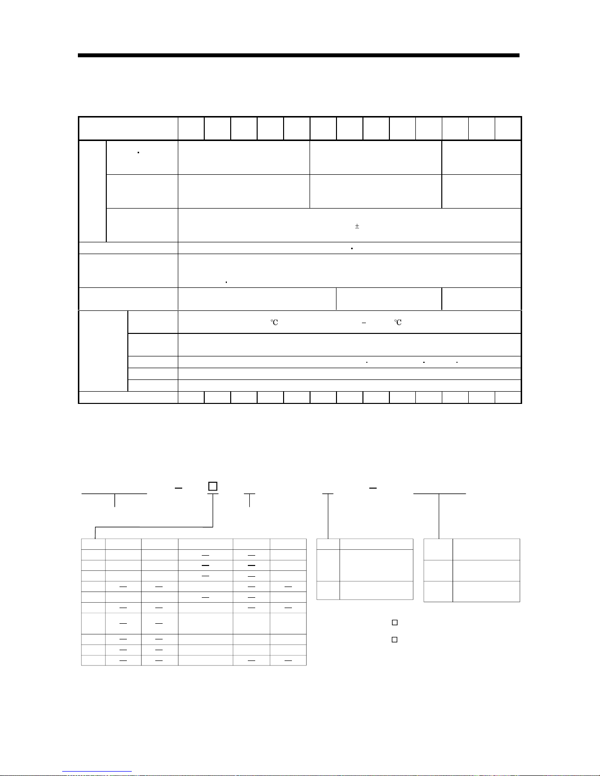
1.4 Model name
MR-J2S B1
10
20
40
60
70
100
200
350
500
700
053, 13
23
43
73 73
43
23
053, 13
52, 53
81, 102, 103
121, 201, 152,
202, 153, 203
301, 352, 353
502
702
353, 503
203 202
352, 502
103, 153
152
72, 73
13
23
43
HC-KFS HC-MFS HC-SFS HC-RFS HC-UFS
Mitsubishi general-purpose
AC servo amplifier series name
Compatible motor list
B: SSCNET compatibility
Symbol
Note. The standard specifications comply with the EN, UL and cUL Standards.
Symbol
Power supply
None
1
Three-phase 200VAC
or single-phase
230VAC (Note 1)
Single-phase 100VAC
(Note 2)
Note: 1. Single-phase 230VAC is
for only the servo amplifier
of MR-J2S-70 or less.
2. For only the servo amplifier
of MR-J2S-40 or less.
Symbol
PY096
S096
Full closed control
compatible amplifier
MR-J2S-B type
0.05 to 3.5kw
MR-J2S-B type
5.0, 7.0kw
PY096
1 - 4
1. FUNCTIONS AND CONFIGURATION
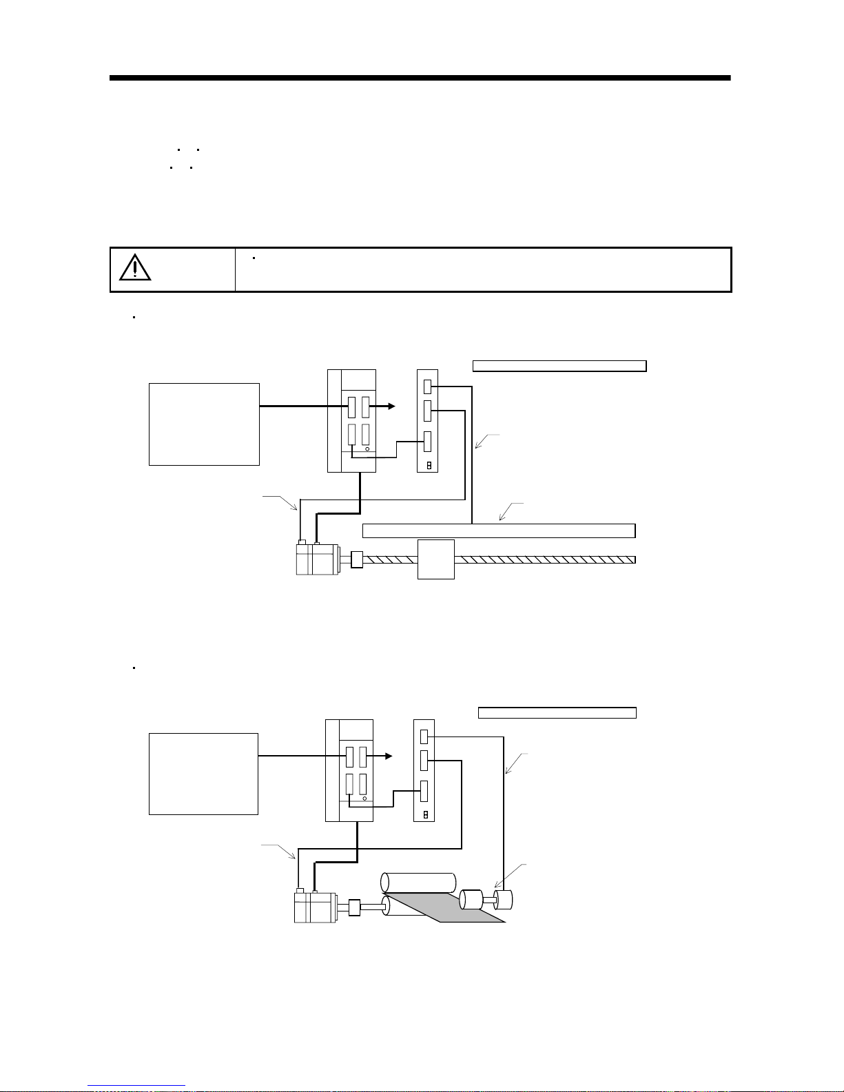
1.5 System configuration
(1) When A
B Z differential input interface unit (MR-J2S-CLP01) is used
The A
B Z differential input interface unit (MR-J2S-CLP01) converts external ABZ phase pulses
into a position feedback signal that can be used for serial communication.
Full closed control is enabled by connecting the output of the MR-J2S-CLP01 to the servo amplifier
encoder connector.
CAUTION
When the MR-J2S-CLP01 is used, a linear scale without Z phase cannot be
connected. Use a linear scale that has the Z phase.
System configuration example 1 (when ABZ pulse train-specified linear scale is used)
SSCNET controller
Servo amplifier
Position
command
control signal
CN1A
CN1B
CN2
CN2
SSCNET
Encoder signal
Linear scale
A, B, Z phase output (ALM output)
ABZ differential input I/F unit
Servo motor
To other
axis
General-purpose pulse output linear scale
MR-J2S-CLP01
Note 1. A linear scale without Z phase cannot be connected.
2. No compatibility with an absolute position detection system.
System configuration example 2 (when ABZ phase pulse train-specified rotary encoder is used)
SSCNET controller
Servo amplifier
Position
command
control signal
CN1A
CN1B
CN2
CN2
SSCNET
Encoder signal
Rotary encoder
A, B, Z phase output
(ALM output)
ABZ differential input I/F unit
Servo motor
To other
axis
General-purpose pulse output encoder
MR-J2S-CLP01
Note 1. A rotary without Z phase cannot be connected.
2. No compatibility with an absolute position detection system.
3. In this example, full closed control cannot be performed if there is no stock (work).
1 - 5
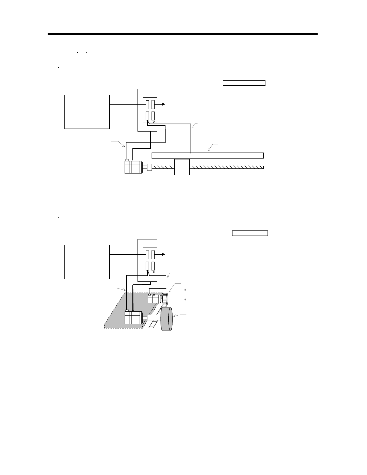
1. FUNCTIONS AND CONFIGURATION
(2) When A B Z differential input interface unit (MR-J2S-CLP01) is not used
System configuration example 3 (when serial communication-specified linear scale is used)
SSCNET controller
Servo amplifier
Position
command
control
signal
CN2
SSCNET
Encoder signal
Linear scale
Serial communication signal cable
Servo motor
To other axis
Serial I/F linear scale
Note 1. When an ABS type linear scale is used, this example is compatible with an absolute position detection system. Note that
the battery (MR-BAT) is not needed.
System configuration example 4 (when serial communication-specified servo motor is used)
SSCNET controller
Servo amplifier
Position
command
control
signal
CN2
SSCNET
Encoder signal
Drive section
Serial communication signal cable
Driving servo
motor
To other axis
Serial I/F encoder
Position detection section (detecting servo
motor and pulley)
Use the HC-MFS/KFS series servo motor.
(131072p/rev resolution)
No compatibility with absolute position
detection.
Note 1. Use the HC-KFS series or HC-MFS series servo motor in the position detection section.
2. No compatibility with an absolute position detection system.

1 - 6
1. FUNCTIONS AND CONFIGURATION
MEMO
2 - 1
2. LINEAR SCALES
2 LINEAR SCALES
Contact the linear scale manufacturer for details of the linear scales such as the specifications,
performance and warranties.
2.1 Compatible linear scale list
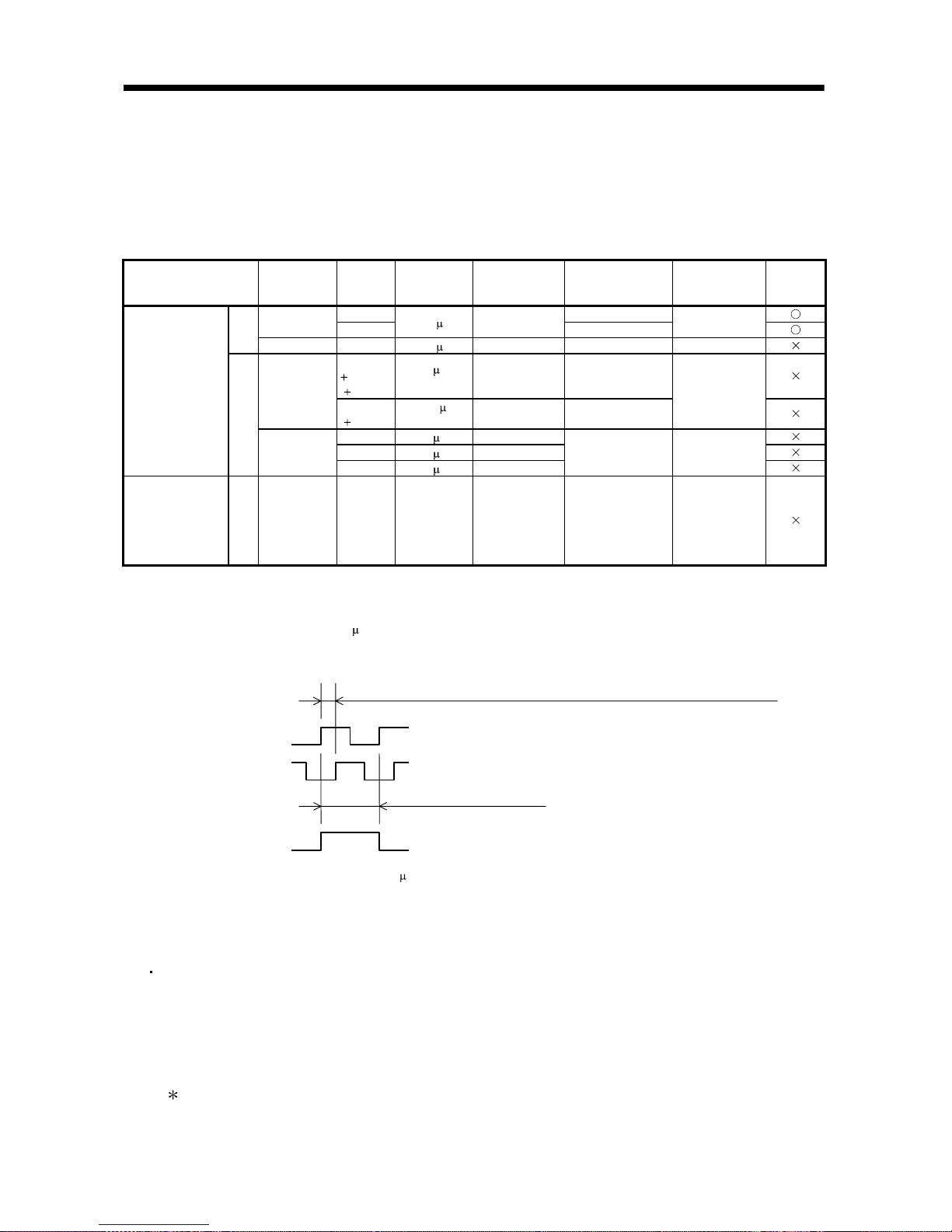
Scale Type Manufacturer Model Resolution
Rated Speed
(Note 1)
Effective
Measurement
Length (Maximum)
Communication
System
Absolute
Position
System
AT343A 3000mm
Mitutoyo
AT543A
0.05 m2.0m/s
1500mm
2 wire type
ABS
type
Heidenhain LC491M 0.05
m 2.0m/s 2040mm 4 wire type
SL710
PL101R
MJ830
0.2
m
(Note 2)
6.4m/s 3000mm
Sony
Precision
Technology
SH13
MJ830
0.005
m
(Note 2)
1.4m/s 1240mm
2 wire type
RGH26P 5.0 m4.0m/s
RGH26Q 1.0 m3.2m/s
Mitsubishi serial
interface
compatibility
INC
type
Renishaw
RGH26R 0.5
m1.6m/s
70000mm 2 wire type
A/B/Z phase
differential output
(MR-CLP01 used)
A/B/Z signal
required
(Note 3)
INC
type
Not specified (Note 3)
Scale
dependent
(Note 4)
Scale
dependent
Scale dependent 2 wire type
Note 1. The upper limit value of the linear servo motor speed is the lower value of the maximum speed of the linear servo motor and the
rated speed of the linear scale.
2. Changes depending on the setting of the interpolator (MJ830: Sony Precision Technology make). Set the resolution within the
range of the minimum resolution to 5
m.
3. The phase difference between the A-phase pulse and B-phase pulse must be 500ns or more, and the Z-phase pulse width be
equivalent to one cycle of the A-phase pulse. Also, the Z phase must be synchronized with the A phase/B phase.
4. The permissible resolution range is 0.005 to 5
m. Select the linear scale within this range.
[About handling of the linear scale]
If the linear scale is mounted improperly, for example, an alarm, position shift, etc. may occur.
In such cases, also check the mounting of the linear scale.
General check items of the linear scale
(a) Check that the gap between the head and scale is proper.
(b) Check the scale head for rolling and yawing (looseness of scale head section).
(c) Check the scale surface for contamination and scratches.
(d) Check that the vibration and temperature are within the operating range.
(e) Check that the speed is within the permissible range without overshooting.
For detailed check items, contact the linear scale manufacturer.
A phase
B phase
Phase difference between A phase and B phase: 500ns or more
Z phase
One cycle of A phase
2 - 2
2. LINEAR SCALES
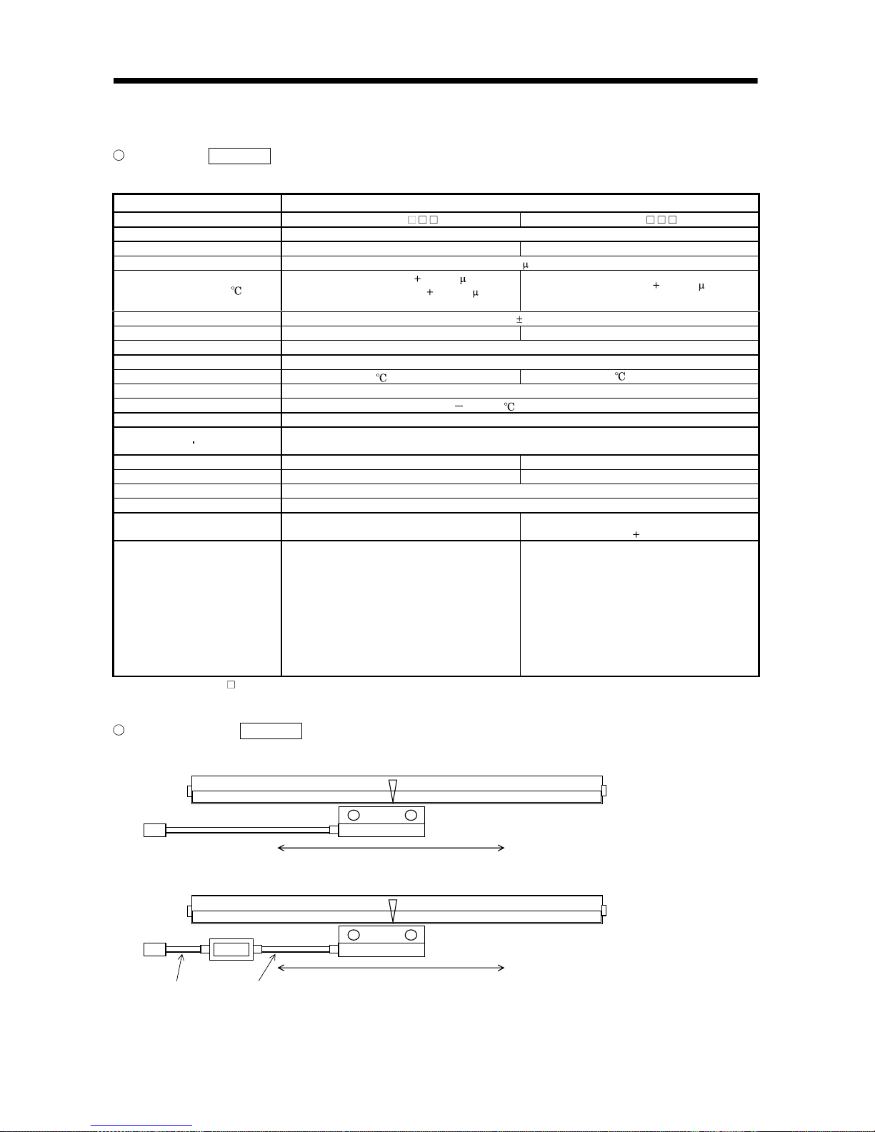
2.1.1 Mitutoyo make linear scales (ABS type)
Specifications Reference
Contact Mitutoyo for the specifications of these linear scales.
Item Specifications
Model AT343A- AT543ASystem Capacitive, photoelectric, combined type
Effective measurement length 100 to 3000mm 100 to 1500mm
Resolution 0.05 m
Indication accuracy (20 )
100 to 1500mm: 3
3L/1000 m
1600mm to 3000mm: 5
5L/1000 m
L: Effective measurement length
100 to 1500mm: 3
3L/1000 m
L: Effective measurement length
Supply power voltage 5V 5%
Current consumption Max.250mA Max.270mA
Rated response speed 2.0m/s
Maximum response speed 2.0m/s
Operating temperature range 0 to 45 (non-freezing) 0 to 50 (non-freezing)
Operating humidity range 20 to 80%RH (non-condensing)
Storage temperature range 20 to 70 (non-freezing)
Storage humidity range 20 to 80%RH (non-condensing)
Dust tightness water tightness
IP53 or equivalent
(in the indication method given in the instruction manual of the Mitutoyo make linear scale)
Vibration resistance 100m/s2 (55 to 2000Hz) 150m/s2 (55 to 2000Hz)
Shock resistance 150m/s2 (1/2sin, 11ms) 200m/s2 (1/2sin, 11ms)
Sliding force 5N or less
Output signal Serial communication compatibility
Output cable
Mitutoyo make option
Part No. 09BAA598A to C:0.2, 2, 3m
Supplied as standard
Head cable 5m
output cable 1m
Connection cable
(Mitsubishi option)
Refer to the standard connection example in
Chapter 3 and fabricate the cable.
When the MR-J2SCLCBL02M-P-H is used,
any of the following Mitsubishi cables can also
be used (Note 1).
Output cable length 0.2m: MR-JCCBL2, 5,
10M-H
2m: MR-JCCBL2, 5M-H
3m: MR-JCCBL2M-H
Refer to the standard connection example in
Chapter 3 and fabricate the cable.
When the MR-J2SCLCBL02M-P-H is used,
any of the following Mitsubishi cables can also
be used (Note 1).
MR-JCCBL2, 5, 10M-H
Note 1. The MR-JCCBL M-L and MR-JCCBL20M-H and more (20m and more) cannot be used.
2. The battery (MR-BAT) is not required to configure an absolute position detection system.
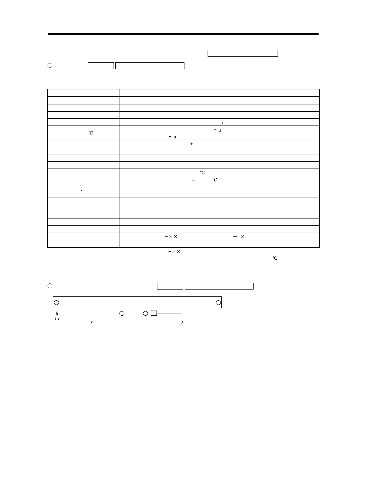
Scale unit structure Reference
Home position
Decreasing direction
Mitutoyo
AT343A
Output cable
Home position
Mitutoyo
AT543A
Output cable Head cable
Increasing direction
Decreasing direction Increasing direction
2 - 3
2. LINEAR SCALES
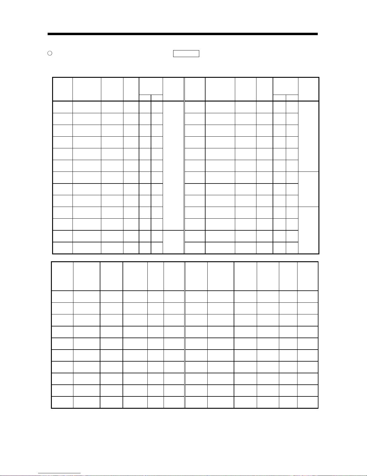
AT343A and AT543A mounting dimension tables Reference (Dimension unit: mm)
The following tables indicate L0 to L4 and number of mounting blocks or number of fixing holes in the
outline drawings shown on the next page.
Mounting
Block Fixing
Pitch
Mounting
Block Fixing
Pitch
Model
Effective
Measurement
Length
L0
Maximum
Moving
Length
L1
Full
Length
L2
L3 L4
Number of
Mounting
Blocks
(pcs.)
Model
Effective
Measurement
Length
L0
Maximum
Moving
Length
L1
Full
Length
L2
L3 L4
Number of
Mounting
Blocks
(pcs.)
AT343A-
300
300 330 440 220 150
AT343A-
1300
1300 1360 1470 735 325
AT343A-
350
350 380 490 245 175
AT343A-
1400
1400 1460 1570 785 350
AT343A-
400
400 430 540 270 200
AT343A-
1500
1500 1560 1670 835 375
AT343A-
450
450 480 590 295 225
AT343A-
1600
1600 1690 1800 900 400
AT343A-
500
500 540 650 325 250
AT343A-
1700
1700 1790 1900 950 425
AT343A-
600
600 650 760 380 300
AT343A-
1800
1800 1890 2000 1000 450
5
AT343A-
700
700 760 870 435 350
AT343A-
2000
2000 2100 2210 1105 335
AT343A-
750
750 810 920 460 375
AT343A-
2200
2200 2300 2410 1205 370
AT343A-
800
800 860 970 485 400
AT343A-
2400
2400 2500 2610 1305 400
7
AT343A-
900
900 960 1070 535 450
AT343A-
2500
2500 2600 2710 1355 315
AT343A-
1000
1000 1060 1170 585 500
3
AT343A-
2600
2600 2700 2810 1405 325
AT343A-
1100
1100 1160 1270 635 275
AT343A-
2800
2800 2900 3010 1505 350
AT343A-
1200
1200 1260 1370 685 300
5
AT343A-
3000
3000 3050 3210 1605 375
9
Model
Effective
Measurement
Length
L0
Maximum
Moving
Length
L1
Mounting
Hole Position
L2
Full
Length
L3
Number of
Fixing
Holes
(n) (pcs.)
Model
Effective
Measurement
Length
L0
Maximum
Moving
Length
L1
Mounting
Hole
Position
L2
Full
Length
L3
Number of
Fixing
Holes
(n)
(pcs.)
AT543A-
100
100 120 12.5 225 3
AT543A-
700
700 720 12.5 825 9
AT543A-
150
150 170 37.5 275 3
AT543A-
750
750 770 37.5 875 9
AT543A-
200
200 220 12.5 325 4
AT543A-
800
800 820 12.5 925 10
AT543A-
250
250 270 37.5 375 4
AT543A-
900
900 920 12.5 1025 11
AT543A-
300
300 320 12.5 425 5
AT543A-
1000
1000 1020 12.5 1125 12
AT543A-
350
350 370 37.5 475 5
AT543A-
1100
1100 1120 12.5 1225 13
AT543A-
400
400 420 12.5 525 6
AT543A-
1200
1200 1220 12.5 1325 14
AT543A-
450
450 470 37.5 575 6
AT543A-
1300
1300 1320 12.5 1425 15
AT543A-
500
500 520 12.5 625 7
AT543A-
1400
1400 1420 12.5 1525 16
AT543A-
600
600 620 12.5 725 8
AT543A-
1500
1500 1520 12.5 1625 17
2 - 4
2. LINEAR SCALES
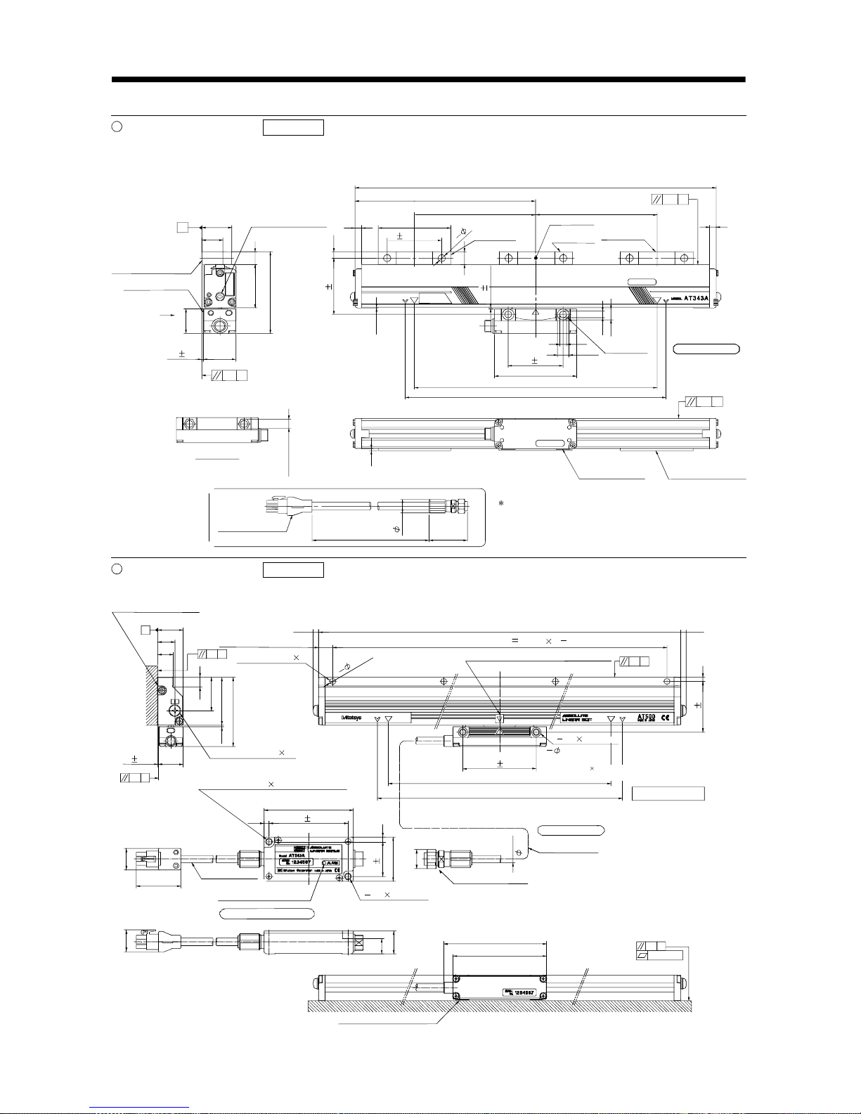
AT343A outline drawing Reference (Dimension unit: mm)
Effective measurement length 300mm to 3000mm
This outline drawing is based on the data from Mitutoyo. Contact Mitutoyo for this outline drawing.
Spot facing
depth 5
7
7
11.6
A
32.5
23
X
36
29
50.5 15
95.5
0.1
A
2.5
7.5
807
1
5
0.2
G
(42)
8
12.6
L
(
0.5
)
Scale body mounting
surface
Detection head
mounting surface
Air supply port (M5)
(Provided at both ends)
Full length L2
Mounting block fixing pitch L3
Mounting block fixing pitch L4 Mounting block fixing pitch L4
Elastical ly fixing
area
Mounting block
Completely
fixing area
Elastically
fixing area
Spot facing
depth 6.5
G: Machine guide
Effective measurement length L0
Maximum moving lengt h L1
View X
11 (hexagon)
Detection head
mounting surface
Scale body mounting
surface
Option (L = any of three different len gths, 0.2m, 2m, 3m)
Signal cable
(Vinyl sheathed)
( 16)
1.5 0.2
66 0.3
60 0.2
60 0.2
90
2
8
The signal cable is optional.
(Part No.09BAA598A to C: 0.2m, 2m, 3m)
1.5 0.2
0.2 G
AT543A outline drawing Reference (Dimension unit: mm)
This outline drawing is based on the data from Mitutoyo. Contact Mitutoyo for this outline drawing.
Air supply port (M5 0.8)
A
0.1
G
8.5
30
43
62
(1.5)
0.1
G
4
(17)
40
4.5
80
4.5
(40)
(
19.2
)
(19.6)
20
13.4
92
84
0.1
G
0.03/100
AR
Scale unit mounting surface
(Provided on both sides)
Mounting hole position: L2
(4.8)
Fixing screw: M4 0.8
(L = 18mm or more)
Full length: L3
(4.8)
Mounting hole pitch P 100mm (n 1)
Position where absolute value data is zero
(Nearly at scale center)
2 8 spot facing
depth 5(One side only)
2 M6 1
(through)
60 0.2
Fixing screw: M4 0.8L = 20mm or more,
or can be fixed with M6 screw from rear side.
Effective measurement length: L0
Maximum moving length: L1
G: Machine guide
Fixing screw: M4 0.8L = 18mm or more,
or can be fixed with M6 screw from rear side.
Output cable
(Vinyl sheath)
Alarm display LED window
Waterproof connector
2 M6 1
(through)
Scale uni t
Head cable
(Vinyl sheath)
Interface unit
Scale unit mounting surface
22
0.1
A
1 0.1
n
5
(
H
ol
e)
45.2 0.2
23
14
15.5
71 0.2
31 0.2
6.5
2 - 5
2. LINEAR SCALES
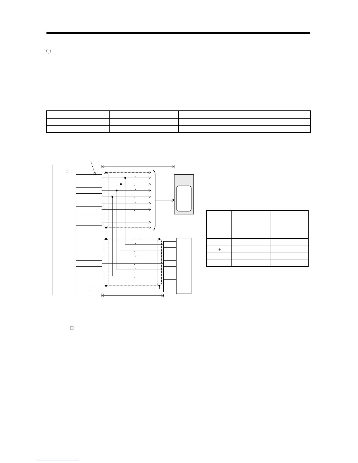
Connection cable connection examples (1)
The following cable wiring examples assume that the linear scale is connected directly to CN2 of the servo
amplifier.
(1) Connection example of up to 5m wiring length (This connection example assumes that the following
operating combination is satisfied.)
[Operating combination]
Used Wire Size Scale Model Scale Side Output Cable Specifications
AWG24 AT343A Mitutoyo make output cable 2m
AWG24 AT543A Mitutoyo make output cable 1m
[Connection example]
10120-3000PE, 10320-52F0- 008
(3M make or equi valent )
(Note 1)
Mitutoyo make linear scale
19
12
20
11
7
17
1
P5
LG
P5
LG
M
R
MR
R
LG
6
16
Plate
M
D
MD
R
S
D
P5
LG
R
Q
/
RQ
P5
LG
F
G
(Note 2)
CN2
Servo motor
Encoder
(Note 3)
Servo ampli fier
MR-J2S -
B
-PY096/S096
50m or less (2 wire type)
5m or less
Note 1. Do not connect the linear scale that is not indicated in this specification.
2. Connect the shield wire to the plate (ground plate) in the connector securely.
3. For the wiring to the servo motor, refer to the standard connection examples in Chapter 3 and the Instruction Manual of the MR-
J2S-
B standard model.
4. Contact the scale manufacturer for detailed specifications such as the combinations, models, types, etc. of the linear scale side
output cable and connector.
[Linear scale side connector] (Note 4)
Applicable
Housing
172161-9
(Tyco Electronics
or equivalent)
RDAD-15S-LNA
(Hirose Electric
or equivalent)
RQ 1 7
/RQ 2 8
P5 ( 5V) 7 3, 4
LG (0V) 8 1, 2
FG 9 15
2 - 6
2. LINEAR SCALES
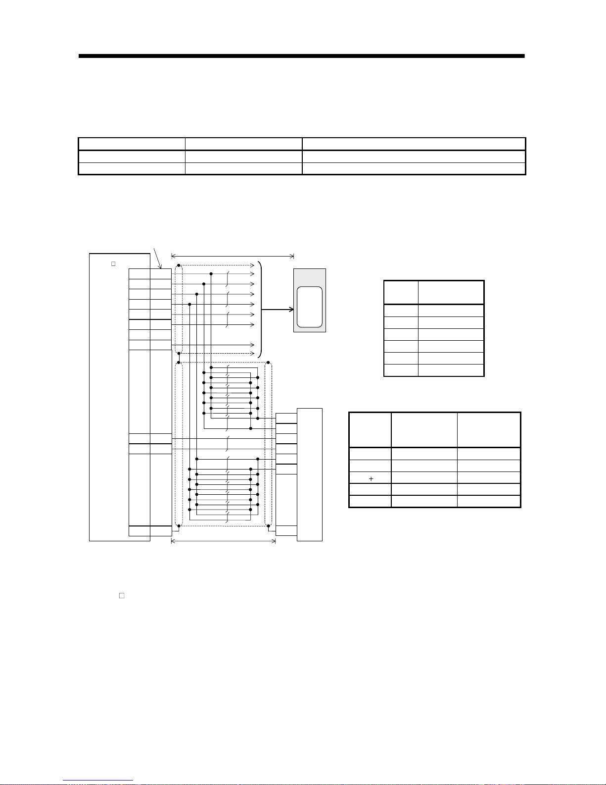
(2) Connection example of 5m to 30m wiring length (This connection example assumes that the following
operating combination is satisfied.)
[Operating combination]
Used Wire Size Scale Model Scale Side Output Cable Specifications
AWG24 AT343A Mitutoyo make output cable 0.2m
AWG22 AT543A Mitutoyo make output cable 1m
[Connection example]
The wiring length is up to 30m. Depending on the wiring length, however, the number of LG and P5
connections must be changed according to the following table.
(Note 1)
Mitutoyo make linear scale
19
12
20
11
7
17
1
P5
LG
P5
LG
M
RMRR
LG
6
16
Plate
MD
MD
R
SD
P5
LG
RQ
/RQ
P5
LG
FG
(Note 2)
CN2
Servo motor
Encoder
(Note 3)
Servo amplifier
MR-J2S -
B
-PY096/S096
10120-3000PE, 10320-52F0-0 08
(3M make or equivalent )
50m or less (2 wire type)
30m or less
Note 1. Do not connect the linear scale that is not indicated in this specification.
2. Connect the shield wire to the plate (ground plate) in the connector securely.
3. For the wiring to the servo motor, refer to the standard connection examples in Chapter 3 and the Instruction Manual of the MR-
J2S-
B standard model.
4. Contact the scale manufacturer for detailed specifications such as the combinations, models, types, etc. of the linear scale side
output cable and connector.
Wiring
Length
Number of LG and
P5 Connections
to 5m 2 parallel
to 10m 4 parallel
to 15m 6 parallel
to 20m 8 parallel
to 25m 10 parallel
to 30m 12 parallel
[Linear scale side connector] (Note 4)
Applicable
Housing
172161-9
(Tyco Electronics
or equivalent)
RDAD-15S-LNA
(Hirose Electric or
equivalent)
RQ 1 7
/RQ 2 8
P5 ( 5V) 7 3, 4
LG (0V) 8 1, 2
FG 9 15
2 - 7
2. LINEAR SCALES
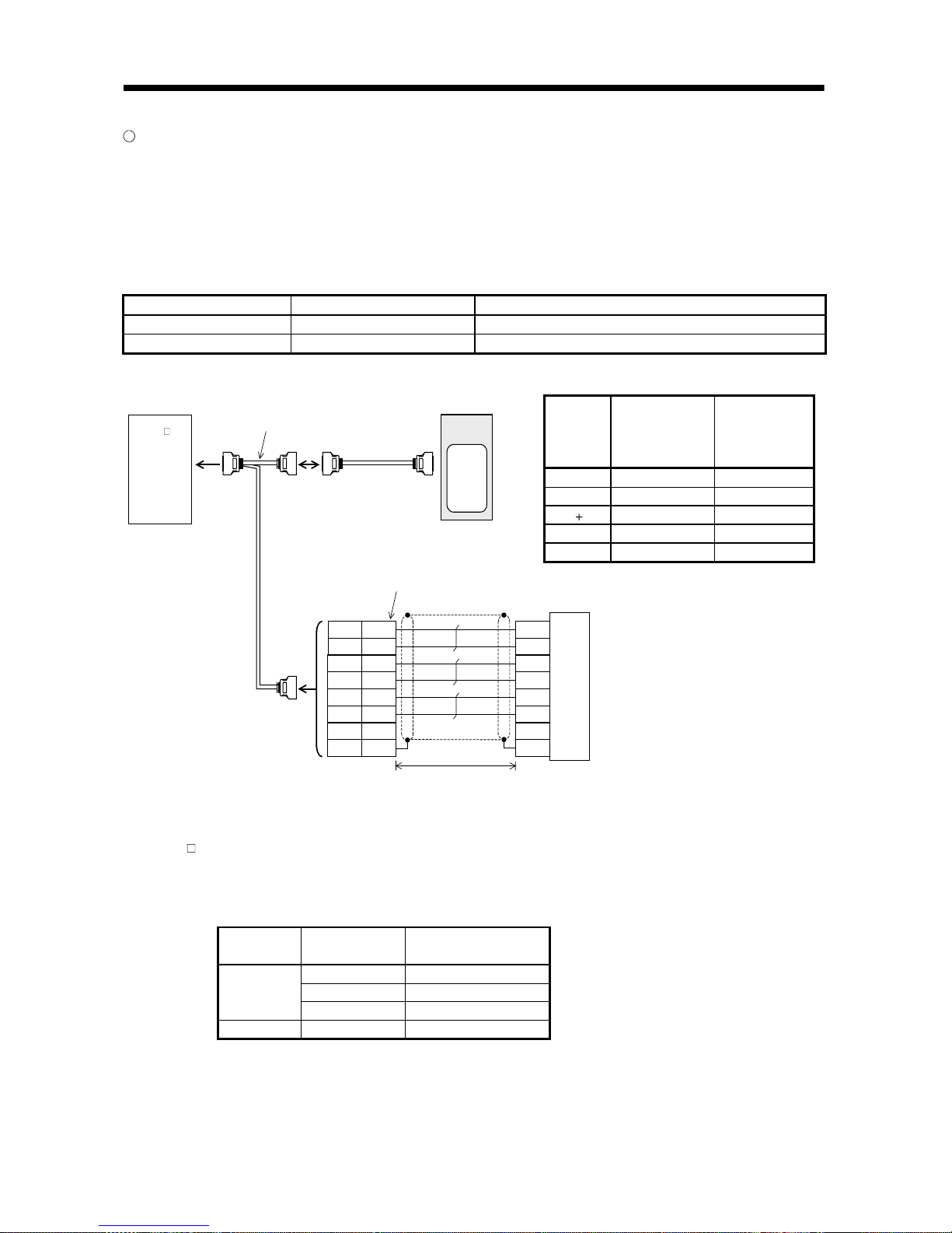
Connection cable connection examples (2)
The following cable wiring examples assume that the linear scale is connected to CN2 of the servo
amplifier using the option cable MR-J2SCLCBL02M-P-H.
(1) Connection example of up to 5m wiring length (This connection example assumes that the following
operating combination is satisfied.)
[Operating combination]
Used Wire Size Scale Model Scale Side Output Cable Specifications
AWG24 AT343A Mitutoyo make output cable 2m
AWG24 AT543A Mitutoyo make output cable 1m
[Connection example]
10120-3000PE, 10320-52F0- 008
(3M or equivalent)
To CN2
Servo motor
Encoder
(Note 1)
Mitutoyo make linear scale
1912P5
LG
7
17
20
11
Plate
M
R
MR
R
P5
LG
S
D
P5
LG
R
Q
/RQ
P5
LG
FG
(Note 2)
(Note 3)
Servo amplifier
MR-J 2S-
B
-PY096/S096
Linear
scale
connector
Option cable
(MR-J2SCLCBL02M-P-H)
5m or less
Note 1. Do not connect the linear scale that is not indicated in this specification.
2. Connect the shield wire to the plate (ground plate) in the connector securely.
3. For the wiring to the servo motor, refer to the standard connection examples in Chapter 3 and the Instruction Manual of the MR-
J2S-
B standard model.
4. Contact the scale manufacturer for detailed specifications such as the combinations, models, types, etc. of the linear scale side
output cable and connector.
5. When the MR-J2SCLCBL02M-P-H is used, the Mitsubishi option cable can be used as the linear scale connection cable.
Scale Model
Scale Side Output
Cable Length
Mitsubishi Option Cable
Model
0.2m MR-JCCBL2, 5, 10M-H
2m MR-JCCBL2, 5M-H
AT343A
3m MR-JCCBL2M-H
AT543A 1m MR-JCCBL2, 5, 10M-H
[Linear scale side connector] (Note 4)
Applicable
Housing
172161-9
(Tyco Electronics
or equivalent)
(Note 5)
RDAD-15S-LNA
(Hirose Electric or
equivalent)
RQ 1 7
/RQ 2 8
P5 ( 5V) 7 3, 4
LG (0V) 8 1, 2
FG 9 15
2 - 8
2. LINEAR SCALES
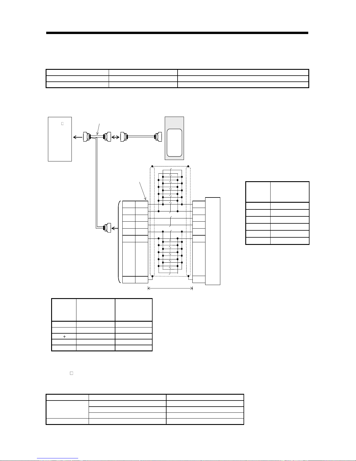
(2) Connection example of 5m to 30m wiring length (This connection example assumes that the following
operating combination is satisfied.)
[Operating combination]
Used Wire Size Scale Model Scale Side Output Cable Specifications
AWG24 AT343A Mitutoyo make output cable 0.2m
AWG22 AT543A Mitutoyo make output cable 1m
[Connection example]
The wiring length is up to 30m. Depending on the wiring length, however, the number of LG and P5
connections must be changed according to the following table.
10120-3000PE, 10320-52F0-008
(3M or equi valent)
To CN2
Servo mot or
Encoder
(Note 1)
Mitutoyo make linear scale
1912P
5LG7
17
20
11
Plat e
M
RMRRP5
LG
SD
P
5
LG
R
Q
/
RQ
P
5
LG
FG
(Note 2)
(Note 3)
Servo ampli fier
MR- J2 S-
B
-PY096/ S096
Linear
scale
connect or
Opti on cabl e
(MR-J2SCLCBL02M-P-H)
30m or less
Note 1. Do not connect the linear scale that is not indicated in this specification.
2. Connect the shield wire to the plate (ground plate) in the connector securely.
3. For the wiring to the servo motor, refer to the standard connection examples in Chapter 3 and the Instruction Manual of the MRJ2S-
B standard model.
4. Contact the scale manufacturer for detailed specifications such as the combinations, models, types, etc. of the linear scale side
output cable and connector.
5. When the MR-J2SCLCBL02M-P-H is used, the Mitsubishi option cable can be used as the linear scale connection cable.
Scale Model Scale Side Output Cable Length Mitsubishi Option Cable Model
0.2m MR-JCCBL2, 5, 10M-H
2m MR-JCCBL2, 5M-H
AT343A
3m MR-JCCBL2M-H
AT543A 1m MR-JCCBL2, 5, 10M-H
[Linear scale side connector] (Note 4)
Applicable
Housing
172161-9
(Tyco Electronics
or equivalent)
(Note 5)
RDAD-15S-LNA
(Hirose Electric or
equivalent)
RQ 1 7
/RQ 2 8
P5 ( 5V) 7 3, 4
LG (0V) 8 1, 2
FG 9 15
Wiring
Length
Number of LG
and P5
Connections
to 5m
2 parallel
to 10m
4 parallel
to 15m
6 parallel
to 20m
8 parallel
to 25m
10 parallel
to 30m
12 parallel
2 - 9
2. LINEAR SCALES
2.1.2 Heidenhain make linear encoder (linear scale) (ABS type) Scheduled to be compatible
Specifications Reference Scheduled to be compatible
Contact Heidenhain for the specifications of this linear encoder (linear scale).
Heidenhain Sales Section No. 2: TEL. (03) 3234-7781
Item Specifications
Model LC491M
System Photoelectric scanning system
Effective measurement length 70 to 2040mm
Resolution 0.05 m
Accuracy grade (20 )
5 m
3 m (up to effective measurement length 1240)
Supply power voltage 5V 5% on the linear encoder side
Current consumption Max.300mA
Rated response speed 2.0m/s
Maximum response speed 2.0m/s
Operating temperature range 0 to 50 (non-freezing) (Note 2)
Storage temperature range 20 to 70
(non-freezing)
Dust tightness water tightness
IP53 (when mounted according to the manual of the Heidenhain make linear encoder)
IP64 (when filled with compressed air)
Vibration resistance
100m/s
2
(DINIEC 68-2-6) without mounting spur
150m/s
2
(DINIEC 68-2-6) with mounting spur
Shock resistance 150m/s2 (DINIEC 68-2-6) (11ms)
Required feeding force 5N or less
Output signal Serial communication compatibility
Output cable 337 439 (17 pin coupling), 367 425 0 (20 pins), etc. (Note 1)
Connection cable Refer to the standard connection example in Chapter 3 and fabricate the cable.
Note 1. When the MR-J2SCLCBL02M-P-H is used, 367 425 (5m or less) can be connected directly.
2. The linear encoder (linear scale) is extremely sensitive to the operating temperature. When it exceeds 50
, an alarm may
occur. It is recommended to pay special attention to the operating temperature and secure the temperature change margins.
3. The battery (MR-BAT) is not required to configure an absolute position detection system.
Linear encoder (linear scale) unit structure Reference Scheduled to be compatible
Decreasing direction Increasing direction
(With the housing section fixed)
Home position
 Loading...