


General-Purpose AC Servo
J2-Super Series
J2-Super Series MR-J2S- B-PY096 MR-J2S- B-S096(5.7kW) Instruction Manual
SSCNET Fully Closed Control Compatible
MODEL
MR-J2S- B-PY096
MR-J2S- B-S096(5.7kW)
INSTRUCTION MANUAL
B
B
A - 1
Safety Instructions
(Always read these instructions before using the equipment.)
Do not attempt to install, operate, maintain or inspect the servo amplifier and servo motor until you have read
through this Instruction Manual, Installation guide, Servo motor Instruction Manual and appended documents
carefully and can use the equipment correctly. Do not use the servo amplifier and servo motor until you have a
full knowledge of the equipment, safety information and instructions.
In this Instruction Manual, the safety instruction levels are classified into "WARNING" and "CAUTION".
WARNING
Indicates that incorrect handling may cause hazardous conditions,
resulting in death or severe injury.
CAUTION
Indicates that incorrect handling may cause hazardous conditions,
resulting in medium or slight injury to personnel or may cause physical
damage.
Note that the CAUTION level may lead to a serious consequence according to conditions. Please follow the
instructions of both levels because they are important to personnel safety.
What must not be done and what must be done are indicated by the following diagrammatic symbols:
: Indicates what must not be done. For example, "No Fire" is indicated by
.
: Indicates what must be done. For example, grounding is indicated by
.
In this Instruction Manual, instructions at a lower level than the above, instructions for other functions, and so
on are classified into "POINT".
After reading this Instruction Manual, always keep it accessible to the operator.
A - 2
1. To prevent electric shock, note the following:
WARNING
Before wiring or inspection, switch power off and wait for more than 15 minutes. Then, confirm the voltage
is safe with voltage tester. Otherwise, you may get an electric shock.
Connect the servo amplifier and servo motor to ground.
Any person who is involved in wiring and inspection should be fully competent to do the work.
Do not attempt to wire the servo amplifier and servo motor until they have been installed. Otherwise, you
may get an electric shock.
Operate the switches with dry hand to prevent an electric shock.
The cables should not be damaged, stressed, loaded, or pinched. Otherwise, you may get an electric shock.
During power-on or operation, do not open the front cover. You may get an electric shock.
Do not operate the converter unit and servo amplifier with the front cover removed. High-voltage terminals
and charging area are exposed and you may get an electric shock.
Except for wiring or periodic inspection, do not remove the front cover even if the power is off. The servo
amplifier is charged and you may get an electric shock.
2. To prevent fire, note the following:
CAUTION
Install the converter unit and servo amplifier, servo motor and regenerative resistor on incombustible
material. Installing them directly or close to combustibles will lead to a fire.
When the servo amplifier has become faulty, switch off the main servo amplifier power side. Continuous
flow of a large current may cause a fire.
When a regenerative resistor is used, use an alarm signal to switch main power off. Otherwise, a
regenerative transistor fault or the like may overheat the regenerative resistor, causing a fire.
3. To prevent injury, note the follow
CAUTION
Only the voltage specified in the Instruction Manual should be applied to each terminal. Otherwise, a burst,
damage, etc. may occur.
Connect the terminals correctly to prevent a burst, damage, etc.
Ensure that polarity ( , ) is correct. Otherwise, a burst, damage, etc. may occur.
During power-on or for some time after power-off, do not touch or close a parts (cable etc.) to the servo
amplifier heat sink, regenerative resistor, servo motor, etc. Their temperatures may be high and you may
get burnt or a parts may damaged.
During operation, never touch the rotating parts of the servo motor. Doing so can cause injury.
A - 3
4. Additional instructions
The following instructions should also be fully noted. Incorrect handling may cause a fault, injury, electric
shock, etc.
(1) Transportation and installation
CAUTION
Transport the products correctly according to their weights.
Stacking in excess of the specified number of products is not allowed.
Do not carry the servo motor by the cables, shaft or encoder.
Do not hold the front cover to transport the controller. The controller may drop.
Install the servo amplifier in a load-bearing place in accordance with the Instruction Manual.
Do not climb or stand on servo equipment. Do not put heavy objects on equipment.
The controller and servo motor must be installed in the specified direction.
Leave specified clearances between the servo amplifier and control enclosure walls or other equipment.
Do not install or operate the servo amplifier and servo motor which has been damaged or has any parts
missing.
Provide adequate protection to prevent screws and other conductive matter, oil and other combustible
matter from entering the servo amplifier and servo motor.
Do not drop or strike servo amplifier or servo motor. Isolate from all impact loads.
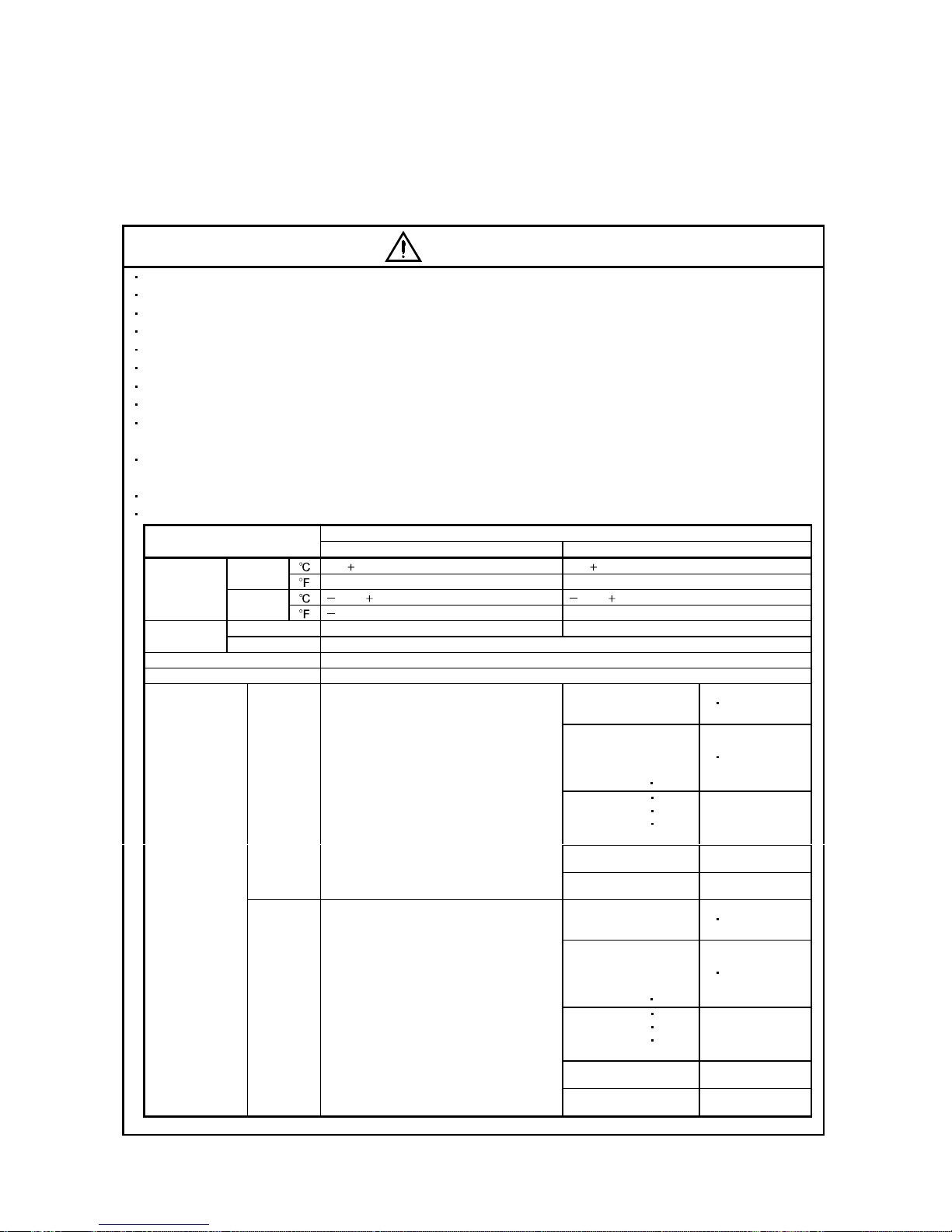
When you keep or use it, please fulfill the following environmental conditions.
Conditions
Environment
Servo amplifier Servo motor
[ ] 0 to 55 (non-freezing) 0 to 40 (non-freezing)
Operation
[
] 32 to 131 (non-freezing) 32 to 104 (non-freezing)
[ ] 20 to 65 (non-freezing) 15 to 70 (non-freezing)
Ambient
temperature
Storage
[
] 4 to 149 (non-freezing) 5 to 158 (non-freezing)
Operation 90%RH or less (non-condensing) 80%RH or less (non-condensing)
Ambient
humidity
Storage 90%RH or less (non-condensing)
Ambience Indoors (no direct sunlight) Free from corrosive gas, flammable gas, oil mist, dust and dirt
Altitude Max. 1000m (3280 ft) above sea level
HC-KFS Series
HC-MFS Series
HC-UFS13 to 73
X
Y : 49
HC-SFS81
HC-SFS52 to 152
HC-SFS53 to 153
HC-RFS Series
HC-UFS 72
152
X
Y : 24.5
HC-SFS121 201
HC-SFS202
352
HC-SFS203
353
HC-UFS202 to 502
X : 24.5
Y : 49
HC-SFS301
HC-SFS502 to 702
X : 24.5
Y : 29.4
[m/s2] 5.9 or less
HA-LFS11K2 to 22K2
X : 11.7
Y : 29.4
HC-KFS Series
HC-MFS Series
HC-UFS 13 to 73
X
Y : 161
HC-SFS81
HC-SFS52 to 152
HC-SFS53 to 153
HC-RFS Series
HC-UFS 72 152
X
Y : 80
HC-SFS121 201
HC-SFS202
352
HC-SFS203
353
HC-UFS202 to 502
X : 80
Y : 161
HC-SFS301
HC-SFS502 to 702
X : 80
Y : 96
(Note)
Vibration
[ft/s
2
] 19.4 or less
HA-LFS11K2 to 22K2
X : 38
Y : 96
Note. Except the servo motor with reduction gear.
A - 4
CAUTION
Securely attach the servo motor to the machine. If attach insecurely, the servo motor may come off during
operation.
The servo motor with reduction gear must be installed in the specified direction to prevent oil leakage.
Take safety measures, e.g. provide covers, to prevent accidental access to the rotating parts of the servo
motor during operation.
Never hit the servo motor or shaft, especially when coupling the servo motor to the machine. The encoder
may become faulty.
Do not subject the servo motor shaft to more than the permissible load. Otherwise, the shaft may break.
When the equipment has been stored for an extended period of time, consult Mitsubishi.
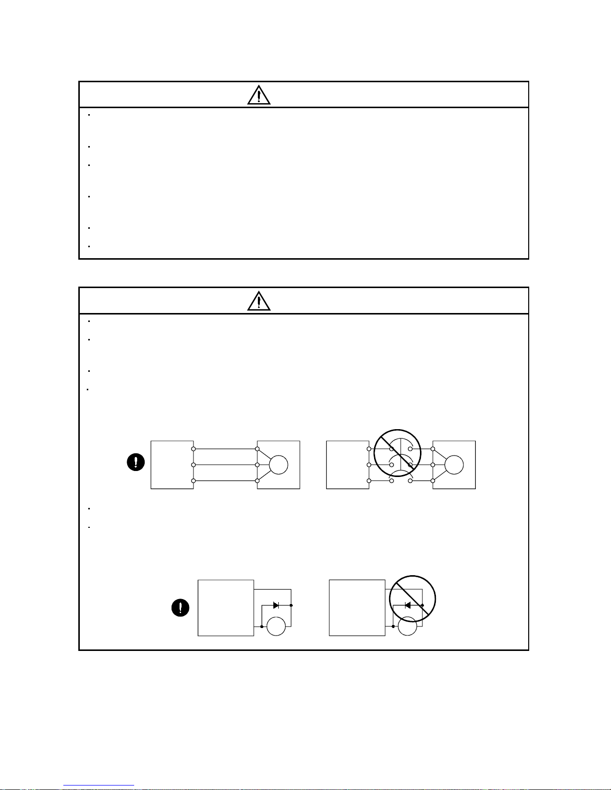
(2) Wiring
CAUTION
Wire the equipment correctly and securely. Otherwise, the servo motor may misoperate.
Do not install a power capacitor, surge absorber or radio noise filter (FR-BIF option) between the servo
motor and servo amplifier.
Connect the output terminals (U, V, W) correctly. Otherwise, the servo motor will operate improperly.
Connect the servo motor power terminal (U, V, W) to the servo motor power input terminal (U, V, W)
directly. Do not let a magnetic contactor, etc. intervene.
U
Servo Motor
M
V
W
U
V
W
U
M
V
W
U
V
W
Servo Amplifier
(drive unit)
Servo Motor
Servo Amplifier
(drive unit)
Do not connect AC power directly to the servo motor. Otherwise, a fault may occur.
The surge absorbing diode installed on the DC output signal of the servo amplifier relay must be wired in
the specified direction. Otherwise, the forced stop (EM1) and other protective circuits may not operate.
COM
(24VDC)
Servo
Amplifier
RA
Control
output
signal
RA
Servo
Amplifier
COM
(24VDC)
Control
output
signal

A - 5
(3) Test run adjustment
CAUTION
Before operation, check the parameter settings. Improper settings may cause some machines to perform
unexpected operation.
The parameter settings must not be changed excessively. Operation will be insatiable.
(4) Usage
CAUTION
Provide a forced stop circuit to ensure that operation can be stopped and power switched off immediately.
Any person who is involved in disassembly and repair should be fully competent to do the work.
Before resetting an alarm, make sure that the run signal of the servo amplifier is off to prevent an
accident. A sudden restart is made if an alarm is reset with the run signal on.
Do not modify the equipment.
Use a noise filter, etc. to minimize the influence of electromagnetic interference, which may be caused by
electronic equipment used near the servo amplifier.
Burning or breaking a servo amplifier may cause a toxic gas. Do not burn or break a servo amplifier.
Use the servo amplifier with the specified servo motor.
The electromagnetic brake on the servo motor is designed to hold the motor shaft and should not be used
for ordinary braking.
For such reasons as service life and mechanical structure (e.g. where a ballscrew and the servo motor
are coupled via a timing belt), the electromagnetic brake may not hold the motor shaft. To ensure safety,
install a stopper on the machine side.
(5) Corrective actions
CAUTION
When it is assumed that a hazardous condition may take place at the occur due to a power failure or a
product fault, use a servo motor with electromagnetic brake or an external brake mechanism for the
purpose of prevention.
Configure the electromagnetic brake circuit so that it is activated not only by the interface unit signals but
also by a forced stop (EM1).
EM1RA
24VDC
Contacts must be open when
servo-off, when an alarm occurrence
and when an electromagnetic brake
interlock (MBR).
Electromagnetic brake
Servo motor
Circuit must be
opened during
forced stop (EM1).
A - 6
CAUTION
When any alarm has occurred, eliminate its cause, ensure safety, and deactivate the alarm before
restarting operation.
When power is restored after an instantaneous power failure, keep away from the machine because the
machine may be restarted suddenly (design the machine so that it is secured against hazard if restarted).
(6) Maintenance, inspection and parts replacement
CAUTION
With age, the electrolytic capacitor of the servo amplifier will deteriorate. To prevent a secondary accident
due to a fault, it is recommended to replace the electrolytic capacitor every 10 years when used in general
environment. Please consult our sales representative.
(7) General instruction
To illustrate details, the equipment in the diagrams of this Instruction Manual may have been drawn
without covers and safety guards. When the equipment is operated, the covers and safety guards must
be installed as specified. Operation must be performed in accordance with this Instruction Manual.
About processing of waste
When you discard servo amplifier, a battery (primary battery), and other option articles, please follow the law of
each country (area).
FOR MAXIMUM SAFETY
These products have been manufactured as a general-purpose part for general industries, and have not
been designed or manufactured to be incorporated in a device or system used in purposes related to
human life.
Before using the products for special purposes such as nuclear power, electric power, aerospace,
medicine, passenger movement vehicles or under water relays, contact Mitsubishi.
These products have been manufactured under strict quality control. However, when installing the product
where major accidents or losses could occur if the product fails, install appropriate backup or failsafe
functions in the system.
EEP-ROM life
The number of write times to the EEP-ROM, which stores parameter settings, etc., is limited to 100,000. If
the total number of the following operations exceeds 100,000, the servo amplifier and/or converter unit may
fail when the EEP-ROM reaches the end of its useful life.
Write to the EEP-ROM due to parameter setting changes
Precautions for Choosing the Products
Mitsubishi will not be held liable for damage caused by factors found not to be the cause of Mitsubishi;
machine damage or lost profits caused by faults in the Mitsubishi products; damage, secondary damage,
accident compensation caused by special factors unpredictable by Mitsubishi; damages to products other
than Mitsubishi products; and to other duties.
A - 7
COMPLIANCE WITH EC DIRECTIVES
1. WHAT ARE EC DIRECTIVES?
The EC directives were issued to standardize the regulations of the EU countries and ensure smooth
distribution of safety-guaranteed products. In the EU countries, the machinery directive (effective in
January, 1995), EMC directive (effective in January, 1996) and low voltage directive (effective in January,
1997) of the EC directives require that products to be sold should meet their fundamental safety
requirements and carry the CE marks (CE marking). CE marking applies to machines and equipment
into which servo amplifiers have been installed.
(1) EMC directive
The EMC directive applies not to the servo units alone but to servo-incorporated machines and
equipment. This requires the EMC filters to be used with the servo-incorporated machines and
equipment to comply with the EMC directive. For specific EMC directive conforming methods, refer to
the EMC Installation Guidelines (IB(NA)67310).
(2) Low voltage directive
The low voltage directive applies also to servo units alone. Hence, they are designed to comply with
the low voltage directive.
This servo is certified by TUV, third-party assessment organization, to comply with the low voltage
directive.
(3) Machine directive
Not being machines, the servo amplifiers need not comply with this directive.
2. PRECAUTIONS FOR COMPLIANCE
(1) Servo amplifiers and servo motors used
Use the servo amplifiers and servo motors which comply with the standard model.
Servo amplifier :MR-J2S-10B-PY096 to MR-J2S-350B-PY096
MR-J2S-500B-S096 to MR-J2S-700B-S096
MR-J2S-10B1-PY096 to MR-J2S-40B1-PY096
Servo motor :HC-KFS
HC-MFS
HC-SFS
HC-RFS
HC-UFS
HA-LFS
HC-LFS
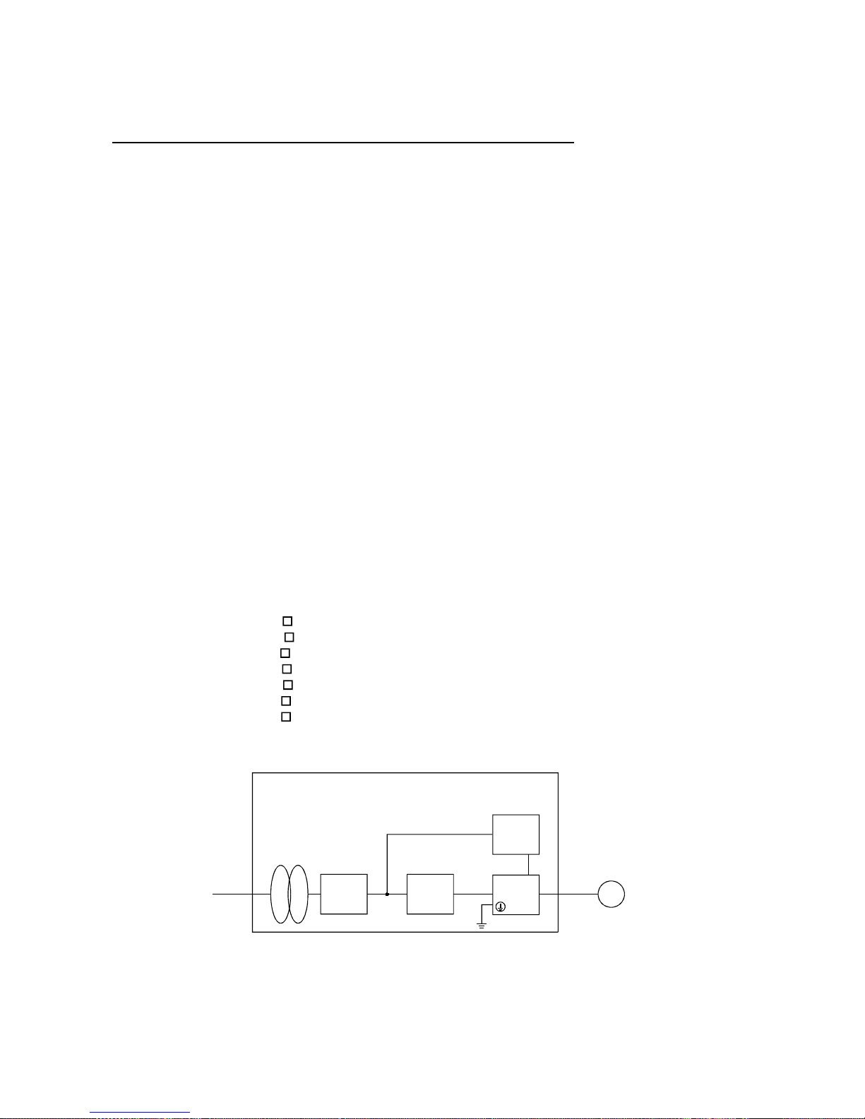
(2) Configuration
Reinforced
insulating
transformer
NFB
MC
SM
No-fuse
breaker
Magnetic
contactor
Reinforced
insulating type
24VDC
power
supply
Servo
amplifier
Servo
motor
Control box
(Note)
Note. The insulating transformer is not required for the 11kW or more servo amplifier.
(3) Environment
Operate the servo amplifier at or above the contamination level 2 set forth in IEC664. For this
purpose, install the servo amplifier in a control box which is protected against water, oil, carbon, dust,
dirt, etc. (IP54).
A - 8
(4) Power supply
(a) Operate the servo amplifier 7kW or less to meet the requirements of the overvoltage category II set
forth in IEC664. For this purpose, a reinforced insulating transformer conforming to the IEC or EN
standard should be used in the power input section.
Since the 11kW or more servo amplifier can be used under the conditions of the overvoltage
category III set forth in IE644, a reinforced insulating transformer is not required in the power
input section.
(b) When supplying interface power from external, use a 24VDC power supply which has been
insulation-reinforced in I/O.
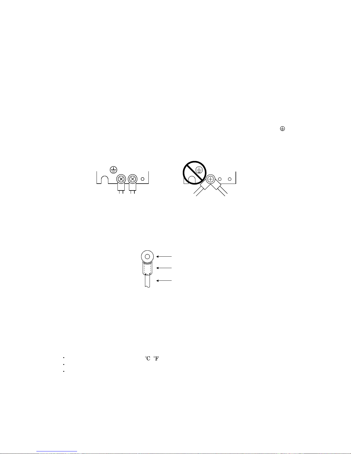
(5) Grounding
(a) To prevent an electric shock, always connect the protective earth (PE) terminals (marked
) of the
servo amplifier to the protective earth (PE) of the control box.
(b) Do not connect two ground cables to the same protective earth (PE) terminal Always connect the
cables to the terminals one-to-one.
PE terminals
PE terminals
(c) If a leakage current breaker is used to prevent an electric shock, the protective earth (PE)
terminals of the servo amplifier must be connected to the corresponding earth terminals.
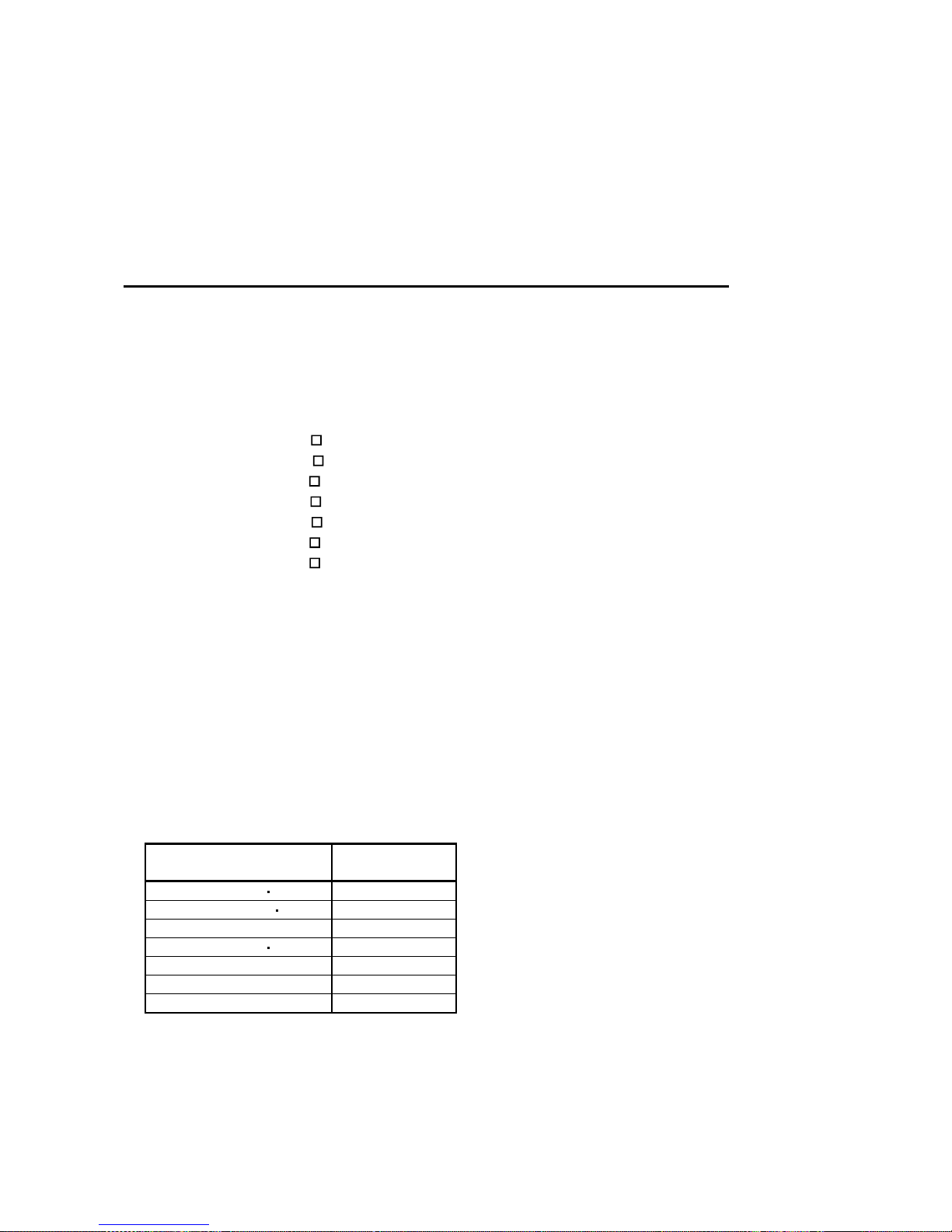
(6) Wiring
(a) The cables to be connected to the terminal block of the servo amplifier must have crimping
terminals provided with insulating tubes to prevent contact with adjacent terminals.
Crimping terminal
Insulating tube
Cable
(b) Use the servo motor side power connector which complies with the EN Standard. The EN Standard
compliant power connector sets are available from us as options.
(7) Auxiliary equipment and options
(a) The no-fuse breaker and magnetic contactor used should be the EN or IEC standard-compliant
products of the models described in Section 12.2.2.
(b) The sizes of the cables described in Section 12.2.1 meet the following requirements. To meet the
other requirements, follow Table 5 and Appendix C in EN60204-1.
Ambient temperature: 40 (104) [ ( )]
Sheath: PVC (polyvinyl chloride)
Installed on wall surface or open table tray
(c) Use the EMC filter for noise reduction.
A - 9
(8) Performing EMC tests
When EMC tests are run on a machine/device into which the servo amplifier has been installed, it
must conform to the electromagnetic compatibility (immunity/emission) standards after it has
satisfied the operating environment/electrical equipment specifications.
For the other EMC directive guidelines on the servo amplifier, refer to the EMC Installation
Guidelines(IB(NA)67310).
CONFORMANCE WITH UL/C-UL STANDARD
(1) Servo amplifiers and servo motors used
Use the servo amplifiers and servo motors which comply with the standard model.
Servo amplifier :MR-J2S-10B-PY096 to MR-J2S-350B-PY096
MR-J2S-500B-S096 to MR-J2S-700B-S096
MR-J2S-10B1-PY096 to MR-J2S-40B1-PY096
Servo motor :HC-KFS
HC-MFS
HC-SFS
HC-RFS
HC-UFS
HA-LFS
HC-LFS
(2) Installation
Install a cooling fan of 100CFM (2.8m
3
/min) air flow 4 in (10.16 cm) above the servo amplifier or
provide cooling of at least equivalent capability.
(3) Short circuit rating
This servo amplifier conforms to the circuit whose peak current is limited to 5000A or less. Having
been subjected to the short-circuit tests of the UL in the alternating-current circuit, the servo
amplifier conforms to the above circuit.
(4) Capacitor discharge time
The capacitor discharge time is as listed below. To ensure safety, do not touch the charging section for
15 minutes after power-off.
Servo amplifier
Discharge time
[min]
MR-J2S-10B(1) 20B(1) 1
MR-J2S-40B(1) 60B 2
MR-J2S-70B to 350B 3
MR-J2S-500B 700B 5
MR-J2S-11KB 4
MR-J2S-15KB 6
MR-J2S-22KB 8
(5) Options and auxiliary equipment
Use UL/C-UL standard-compliant products.

A - 10
(6) Attachment of a servo motor
For the flange size of the machine side where the servo motor is installed, refer to "CONFORMANCE
WITH UL/C-UL STANDARD" in the Servo Motor Instruction Manual.
(7) About wiring protection
For installation in United States, branch circuit protection must be provided, in accordance with the
National Electrical Code and any applicable local codes.
For installation in Canada, branch circuit protection must be provided, in accordance with the Canada
Electrical Code and any applicable provincial codes.

1
CONTENTS
1. FUNCTIONS AND CONFIGURATION 1- 1 to 1- 6
1.1 Overview................................................................................................................................................... 1- 1
1.2 Control block diagram............................................................................................................................. 1- 2
1.3 Specification list....................................................................................................................................... 1- 3
1.4 Model name .............................................................................................................................................. 1- 3
1.5 System configuration............................................................................................................................... 1- 4
2. LINEAR SCALES 2- 1 to 2-30
2.1 Compatible linear scale list .................................................................................................................... 2- 1
2.1.1 Mitutoyo make linear scales (ABS type) ........................................................................................2- 2
2.1.2 Heidenhain make linear encoder (linear scale) (ABS type) ......................................................... 2- 9
2.1.3 Renishaw make linear encoders (linear scales) (INC type)......................................................... 2-15
2.1.4 Sony precision technology make linear encoders (linear scales) (INC type) .............................2-21
2.2 A
B Z-phase differential input Interface unit specifications.......................................................... 2-27
3. SIGNALS AND WIRING 3- 1 to 3- 6
3.1 Standard connection examples of full closed control servo amplifier control signals....................... 3- 1
3.2 Signal
t
erminal explanation ................................................................................................................. 3- 5
3.3 About power-on ........................................................................................................................................ 3- 6
4. OPERATION AND FUNCTIONS 4- 1 to 4-22
4.1 Startup...................................................................................................................................................... 4- 1
4.1.1 Startup procedure............................................................................................................................. 4- 1
4.1.2 Selection of full closed function ....................................................................................................... 4- 2
4.1.3 Selection of full closed encoder communication system................................................................ 4- 3
4.1.4 Setting of full closed encoder polarity............................................................................................. 4- 4
4.1.5 Setting of full closed encoder electronic gear ................................................................................. 4- 5
4.1.6 Confirmation of full closed encoder position data .........................................................................4- 6
4.1.7 Setting of dual feedback switching filter ........................................................................................ 4- 7
4.2 Home position return operation .............................................................................................................4- 8
4.2.1 General precautions ......................................................................................................................... 4- 8
4.2.2 Full closed encoder types and home position return methods ..................................................... 4- 8
4.3 Operation from controller ...................................................................................................................... 4-15
4.3.1 Operation from controller ...............................................................................................................4-15
4.3.2 Controller setting............................................................................................................................. 4-15
4.4 Functions .................................................................................................................................................4-17
4.4.1 Full closed control error detection.................................................................................................. 4-17
4.4.2 Auto tuning function ....................................................................................................................... 4-18
4.4.3 Machine analyzer function ............................................................................................................. 4-18
4.4.4 Test operation .................................................................................................................................. 4-18
4.5 Absolute position detection system....................................................................................................... 4-19

2
4.6 About the MR Configurator ................................................................................................................... 4-20
4.6.1 When current version of MR Configurator
(MRZJW3-SETUP121 to -SETUP151 S/W: E0 version) is used ................................................. 4-20
4.6.2 When full closed compatible MR Configurator
(MRZJW3-SETUP151 S/W: E1 version or later) is used .............................................................4-21
5. PARAMETERS 5- 1 to 5- 8
5.1 Parameter list ...................................................................................................................................... 5- 1
6. TROUBLESHOOTING 6- 1 to 6- 2
6.1 Alarm list.................................................................................................................................................. 6- 1
6.2 Scale error (AL. 2A) details classified by linear scale manufacturer .................................................6- 2
7. OPTIONS AND AUXILIARY EQUIPMENT 7- 1 to 7- 2
7.1 CN2 wiring option cable (MR-J2SCLCBL02M-P-H) ........................................................................... 7- 1

1 - 1
1. FUNCTIONS AND CONFIGURATION
1 FUNCTIONS AND CONFIGURATION
1.1 Overview
This Instruction Manual explains the product that imports a position F/B signal from a full closed
encoder, such as a linear scale, to the MR-J2S-B servo amplifier to perform full closed control.
For the items not described in this Instruction Manual, refer to the MELSERVO-J2S-B Specifications and
Installation Guide and Instruction Manual since they are the same as those of the standard model.
For the specifications of the A
B Z differential input I/F unit MR-J2S-CLP01, refer to the MR-J2S-
CLP01 Installation Guide.
[Items changed from those of the standard model]
1) The A
B Z differential input I/F unit MR-J2S-CLP01 or Mitsubishi serial interface compatible
linear scale is used to detect the position F/B signal of a full closed encoder such as a linear scale.
2) In addition to the full closed control that feeds back the position signal of the full closed encoder,
dual F/B control that feeds back a signal composed of the full closed encoder's position F/B signal
and the motor position F/B signal has been added as an extended function.
3) Function to switch pulse output between the full closed encoder and motor end encoder
4) Addition of restriction on the RS232C communication baud rate (enabled for 9600bps only)
[Functions deleted from the standard model]
1) Speed
torque control
2) Motor-less operation (test operation)
1 - 2
1. FUNCTIONS AND CONFIGURATION
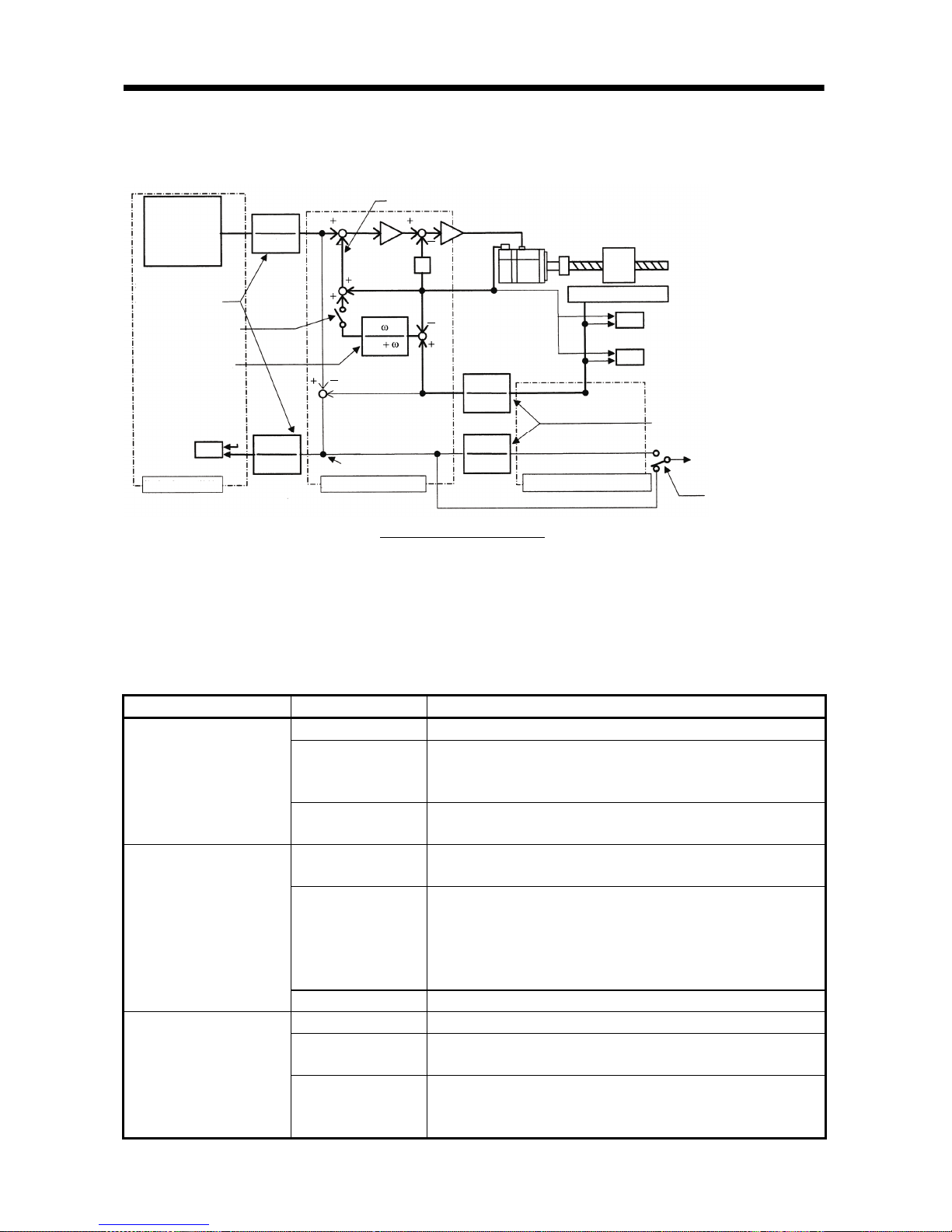
1.2 Control block diagram
A full closed control block diagram is shown below.
Controller
Command pulse
train electronic gear
Parameter No. 6
Full closed selection
Parameter No. 62
(Note 1, 2)
Dual F/B filter
Parameter No. 67
(Note 2)
In-position judgment
INP
Command pulse uni t
1
CMX
CMX
1
S
Dual f/b position signal
Position deviation
Encoder pulse unit
FCM
FCD
FCD
FCM
Servo motor
Linear scale
OP9
FCT
Closed end pulse unit
ABZ phase pulse
output selection
Parameter No. 68
Full closed control error
detection function selection
Parameter No. 62, 63, 64
Full closed electronic gear
Parameter No. 65, 66
Droop pulses (MR Configurator
display, analog monitor)
Droop pulse unit
selection
Parameter No. 68
Full closed control block diagram
S
Note 1. Switching between semi closed control and full closed control can be performed by changing the setting of parameter No. 62.
When semi closed control is selected, control is always performed on the basis of the position data of the motor end encoder
(independently of whether the motor is at a stop or running).
2. When parameter No. 62 "full closed function" is valid, dual F/B control in which the motor F/B signal and full closed encoder F/B
signal are combined by the dual F/B filter in parameter No. 67 is performed.
In this case, full closed control is performed when the motor is at a stop, and semi closed control is performed when the motor
is operating to improve control performance. When 1000 is set as the filter value of parameter No. 67, full closed control is
always performed.
Control Mode Item Description
Feature Position is controlled according to the motor end data.
Advantage
Since this control is insusceptible to machine influence (such as
machine resonance), the gains of the servo amplifier can be
raised and the settling time shortened.
Semi closed control
Disadvantage
If the motor end is at a stop, the machine end may be vibrating
or the machine end accuracy not obtained.
Feature
Position is controlled according to the motor end data and
machine end data.
Advantage
Control is performed according to the motor end data during
operation, and according to the machine end data at a stop in
sequence to raise the gains during operation and shorten the
settling time.
A stop is made with the machine end accuracy.
Dual F/B control
Disadvantage No specific disadvantage.
Feature Position is controlled according to the machine end data.
Advantage
The machine end accuracy is obtained not only at a stop but also
during operation.
Full closed control
Disadvantage
Since this control is susceptible to machine influence (such as
machine resonance), the gains of the servo amplifier do not rise
and the settling time increases.
1 - 3
1. FUNCTIONS AND CONFIGURATION
1.3 Specification list
(1) Servo amplifiers
Servo Amplifier Model
MR-J2S-
10B
-PY096
20B
-PY096
40B
-PY096
60B
-PY096
70B
-PY096
100B
-PY096
200B
-PY096
350B
-PY096
500B
-S096
700B
-S096
10B1
-PY096
20B1
-PY096
40B1
-PY096
Voltage frequency
(Note 1)
Three-phase 200 to 230VAC/50, 60Hz
or single-phase 230VAC/50, 60Hz
(Note 2)
Three-phase 200 to 230VAC/50, 60Hz
(Note 2)
Single-phase 100 to
120VAC/50, 60Hz
Permissible voltage
fluctuation
Three-phase 170 to 253VAC/50, 60Hz
or single-phase 207 to 253VAC/50,
60Hz
Three-phase 170 to 253VAC/50, 60Hz
Single-phase 85 to
127VAC/50, 60Hz
Power
supply
Permissible
frequency
fluctuation
Within
5%
Control system Sine-wave PWM control current control system
Protective functions
Overcurrent shutoff, regenerative overvoltage shutoff, overload shutoff (electronic thermal relay),
servo motor overheat protection, encoder error protection, regeneration error protection,
undervoltage
instantaneous power supply protection, overspeed protection, error excessive protection
Structure Self-cooling, open (IP00) Forced cooling, open (IP00)
Self-cooling,
open (IP00)
Ambient
temperature
0 to 55
(non-freezing), storage: 20 to 65 (non-freezing)
Ambient
humidity
90%RH or less (non-condensing), storage: 90%RH or less (non-condensing)
Ambience Indoors (no direct sunlight), without corrosive gas flammable gas oil mist dust and dirt
Altitude 1000m or less above sea level
Environment
Vibration 5.9m/s
2
or less
Weight (kg) 0.7 0.7 1.1 1.1 1.7 1.7 2.0 2.0 4.9 7.2 0.7 0.7 1.1
Note 1. The rated output capacity and rated speed of a servo motor used with the servo amplifier assumes that the power supply
voltage and frequency are as indicated. They cannot be guaranteed when a power supply voltage drop occurs.
2. The torque characteristic of the servo amplifier used with a servo motor assumes that the voltage is three-phase 200 to 230VAC
or single-phase 230VAC.
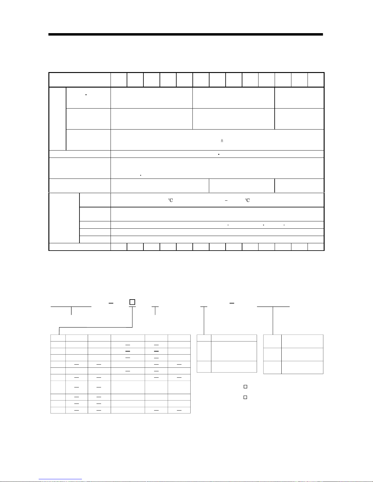
1.4 Model name
MR-J2S B1
10
20
40
60
70
100
200
350
500
700
053, 13
23
43
73 73
43
23
053, 13
52, 53
81, 102, 103
121, 201, 152,
202, 153, 203
301, 352, 353
502
702
353, 503
203 202
352, 502
103, 153
152
72, 73
13
23
43
HC-KFS HC-MFS HC-SFS HC-RFS HC-UFS
Mitsubishi general-purpose
AC servo amplifier series name
Compatible motor list
B: SSCNET compatibility
Symbol
Note. The standard specifications comply with the EN, UL and cUL Standards.
Symbol
Power supply
None
1
Three-phase 200VAC
or single-phase
230VAC (Note 1)
Single-phase 100VAC
(Note 2)
Note: 1. Single-phase 230VAC is
for only the servo amplifier
of MR-J2S-70 or less.
2. For only the servo amplifier
of MR-J2S-40 or less.
Symbol
PY096
S096
Full closed control
compatible amplifier
MR-J2S-B type
0.05 to 3.5kw
MR-J2S-B type
5.0, 7.0kw
PY096
1 - 4
1. FUNCTIONS AND CONFIGURATION
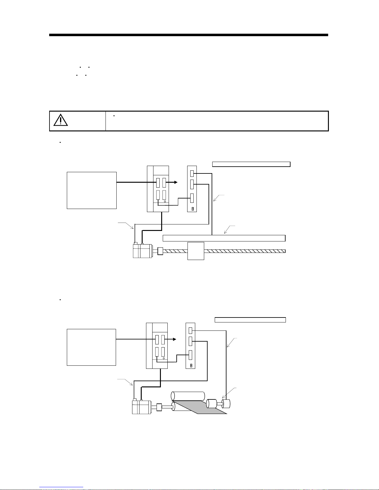
1.5 System configuration
(1) When A
B Z differential input interface unit (MR-J2S-CLP01) is used
The A
B Z differential input interface unit (MR-J2S-CLP01) converts external ABZ phase pulses
into a position feedback signal that can be used for serial communication.
Full closed control is enabled by connecting the output of the MR-J2S-CLP01 to the servo amplifier
encoder connector.
CAUTION
When the MR-J2S-CLP01 is used, a linear scale without Z phase cannot be
connected. Use a linear scale that has the Z phase.
System configuration example 1 (when ABZ pulse train-specified linear scale is used)
SSCNET controller
Servo amplifier
Position
command
control signal
CN1A
CN1B
CN2
CN2
SSCNET
Encoder signal
Linear scale
A, B, Z phase output (ALM output)
ABZ differential input I/F unit
Servo motor
To other
axis
General-purpose pulse output linear scale
MR-J2S-CLP01
Note 1. A linear scale without Z phase cannot be connected.
2. No compatibility with an absolute position detection system.
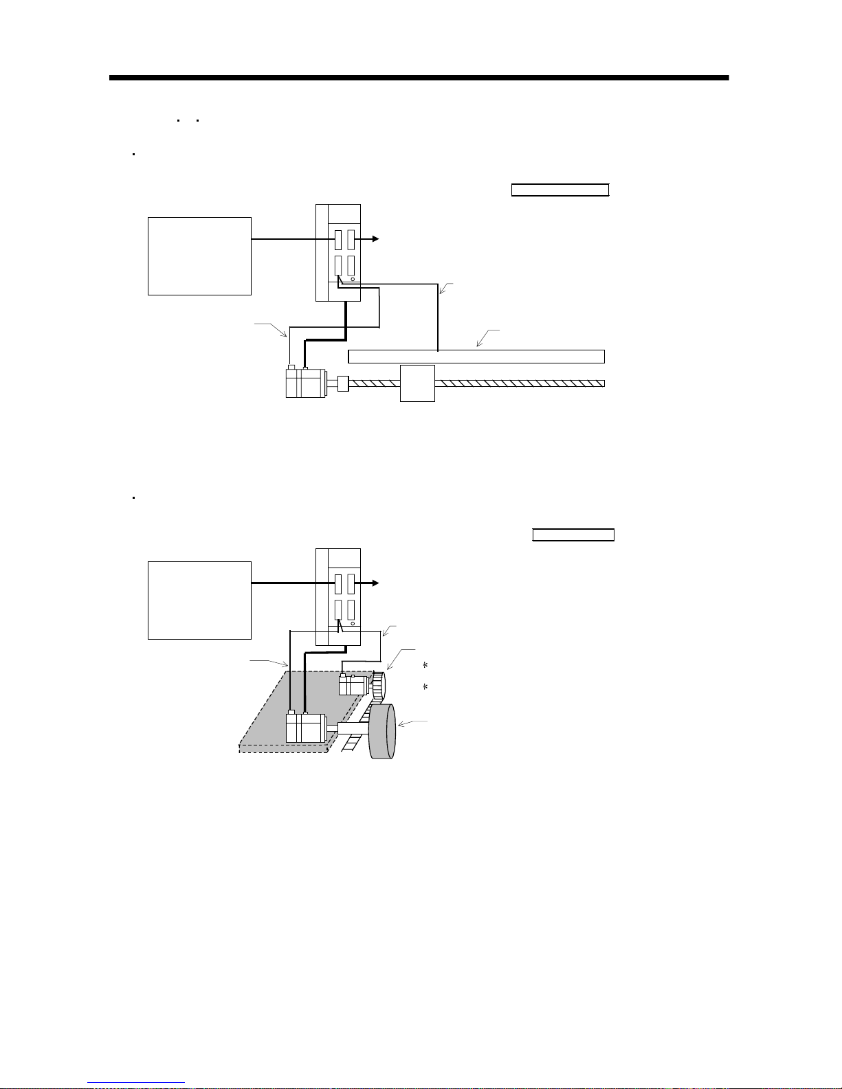
System configuration example 2 (when ABZ phase pulse train-specified rotary encoder is used)
SSCNET controller
Servo amplifier
Position
command
control signal
CN1A
CN1B
CN2
CN2
SSCNET
Encoder signal
Rotary encoder
A, B, Z phase output
(ALM output)
ABZ differential input I/F unit
Servo motor
To other
axis
General-purpose pulse output encoder
MR-J2S-CLP01
Note 1. A rotary without Z phase cannot be connected.
2. No compatibility with an absolute position detection system.
3. In this example, full closed control cannot be performed if there is no stock (work).
1 - 5
1. FUNCTIONS AND CONFIGURATION
(2) When A B Z differential input interface unit (MR-J2S-CLP01) is not used
System configuration example 3 (when serial communication-specified linear scale is used)
SSCNET controller
Servo amplifier
Position
command
control
signal
CN2
SSCNET
Encoder signal
Linear scale
Serial communication signal cable
Servo motor
To other axis
Serial I/F linear scale
Note 1. When an ABS type linear scale is used, this example is compatible with an absolute position detection system. Note that
the battery (MR-BAT) is not needed.
System configuration example 4 (when serial communication-specified servo motor is used)
SSCNET controller
Servo amplifier
Position
command
control
signal
CN2
SSCNET
Encoder signal
Drive section
Serial communication signal cable
Driving servo
motor
To other axis
Serial I/F encoder
Position detection section (detecting servo
motor and pulley)
Use the HC-MFS/KFS series servo motor.
(131072p/rev resolution)
No compatibility with absolute position
detection.
Note 1. Use the HC-KFS series or HC-MFS series servo motor in the position detection section.
2. No compatibility with an absolute position detection system.

1 - 6
1. FUNCTIONS AND CONFIGURATION
MEMO
2 - 1
2. LINEAR SCALES
2 LINEAR SCALES
Contact the linear scale manufacturer for details of the linear scales such as the specifications,
performance and warranties.
2.1 Compatible linear scale list
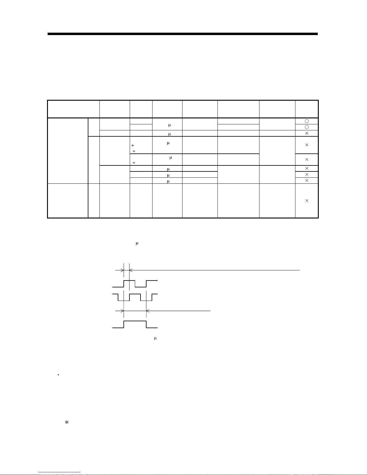
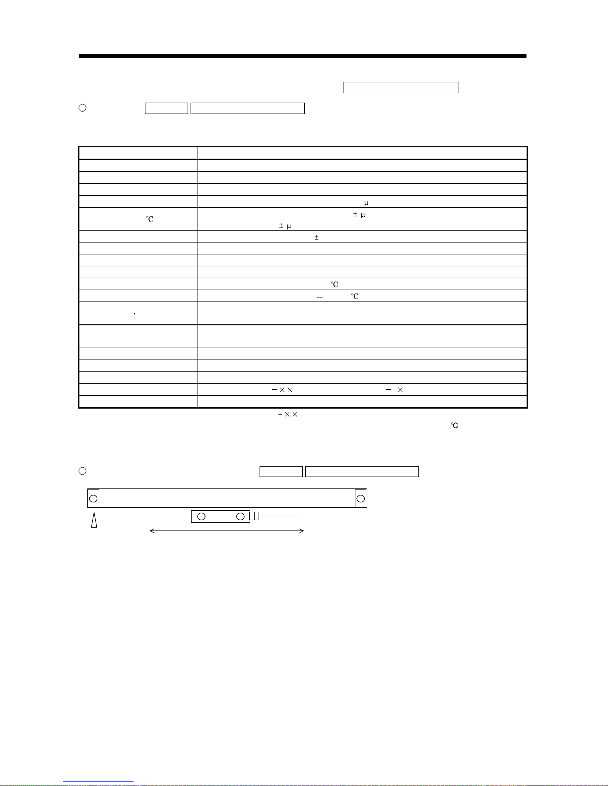
Scale Type Manufacturer Model Resolution
Rated Speed
(Note 1)
Effective
Measurement
Length (Maximum)
Communication
System
Absolute
Position
System
AT343A 3000mm
Mitutoyo
AT543A
0.05 m2.0m/s
1500mm
2 wire type
ABS
type
Heidenhain LC491M 0.05
m 2.0m/s 2040mm 4 wire type
SL710
PL101R
MJ830
0.2
m
(Note 2)
6.4m/s 3000mm
Sony
Precision
Technology
SH13
MJ830
0.005
m
(Note 2)
1.4m/s 1240mm
2 wire type
RGH26P 5.0 m4.0m/s
RGH26Q 1.0 m3.2m/s
Mitsubishi serial
interface
compatibility
INC
type
Renishaw
RGH26R 0.5
m1.6m/s
70000mm 2 wire type
A/B/Z phase
differential output
(MR-CLP01 used)
A/B/Z signal
required
(Note 3)
INC
type
Not specified (Note 3)
Scale
dependent
(Note 4)
Scale
dependent
Scale dependent 2 wire type
Note 1. The upper limit value of the linear servo motor speed is the lower value of the maximum speed of the linear servo motor and the
rated speed of the linear scale.
2. Changes depending on the setting of the interpolator (MJ830: Sony Precision Technology make). Set the resolution within the
range of the minimum resolution to 5
m.
3. The phase difference between the A-phase pulse and B-phase pulse must be 500ns or more, and the Z-phase pulse width be
equivalent to one cycle of the A-phase pulse. Also, the Z phase must be synchronized with the A phase/B phase.
4. The permissible resolution range is 0.005 to 5
m. Select the linear scale within this range.
[About handling of the linear scale]
If the linear scale is mounted improperly, for example, an alarm, position shift, etc. may occur.
In such cases, also check the mounting of the linear scale.
General check items of the linear scale
(a) Check that the gap between the head and scale is proper.
(b) Check the scale head for rolling and yawing (looseness of scale head section).
(c) Check the scale surface for contamination and scratches.
(d) Check that the vibration and temperature are within the operating range.
(e) Check that the speed is within the permissible range without overshooting.
For detailed check items, contact the linear scale manufacturer.
A phase
B phase
Phase difference between A phase and B phase: 500ns or more
Z phase
One cycle of A phase
2 - 2
2. LINEAR SCALES
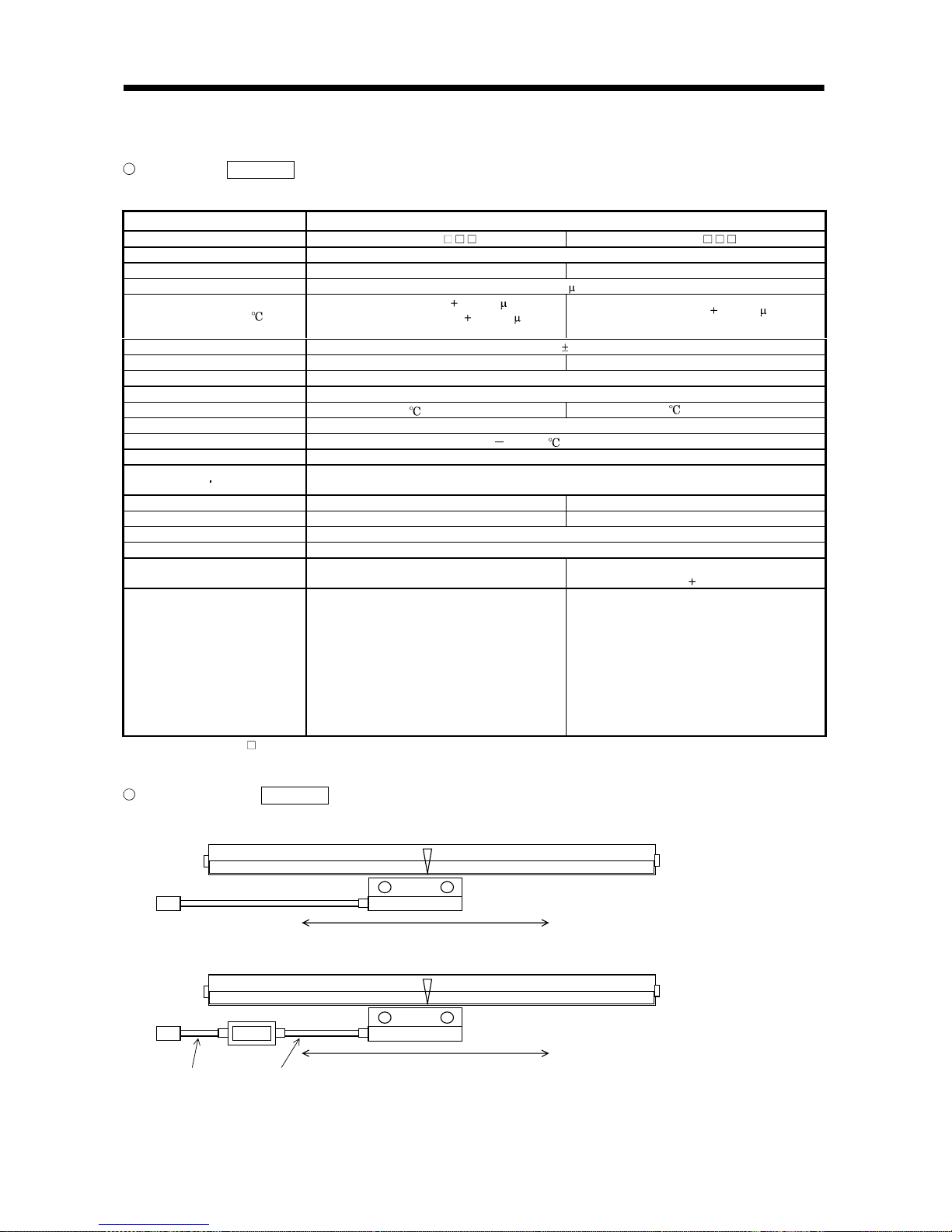
2.1.1 Mitutoyo make linear scales (ABS type)
Specifications Reference
Contact Mitutoyo for the specifications of these linear scales.
Item Specifications
Model AT343A- AT543ASystem Capacitive, photoelectric, combined type
Effective measurement length 100 to 3000mm 100 to 1500mm
Resolution 0.05 m
Indication accuracy (20 )
100 to 1500mm: 3
3L/1000 m
1600mm to 3000mm: 5
5L/1000 m
L: Effective measurement length
100 to 1500mm: 3
3L/1000 m
L: Effective measurement length
Supply power voltage 5V 5%
Current consumption Max.250mA Max.270mA
Rated response speed 2.0m/s
Maximum response speed 2.0m/s
Operating temperature range 0 to 45 (non-freezing) 0 to 50 (non-freezing)
Operating humidity range 20 to 80%RH (non-condensing)
Storage temperature range 20 to 70 (non-freezing)
Storage humidity range 20 to 80%RH (non-condensing)
Dust tightness water tightness
IP53 or equivalent
(in the indication method given in the instruction manual of the Mitutoyo make linear scale)
Vibration resistance 100m/s2 (55 to 2000Hz) 150m/s2 (55 to 2000Hz)
Shock resistance 150m/s2 (1/2sin, 11ms) 200m/s2 (1/2sin, 11ms)
Sliding force 5N or less
Output signal Serial communication compatibility
Output cable
Mitutoyo make option
Part No. 09BAA598A to C:0.2, 2, 3m
Supplied as standard
Head cable 5m
output cable 1m
Connection cable
(Mitsubishi option)
Refer to the standard connection example in
Chapter 3 and fabricate the cable.
When the MR-J2SCLCBL02M-P-H is used,
any of the following Mitsubishi cables can also
be used (Note 1).
Output cable length 0.2m: MR-JCCBL2, 5,
10M-H
2m: MR-JCCBL2, 5M-H
3m: MR-JCCBL2M-H
Refer to the standard connection example in
Chapter 3 and fabricate the cable.
When the MR-J2SCLCBL02M-P-H is used,
any of the following Mitsubishi cables can also
be used (Note 1).
MR-JCCBL2, 5, 10M-H
Note 1. The MR-JCCBL M-L and MR-JCCBL20M-H and more (20m and more) cannot be used.
2. The battery (MR-BAT) is not required to configure an absolute position detection system.
Scale unit structure Reference
Home position
Decreasing direction
Mitutoyo
AT343A
Output cable
Home position
Mitutoyo
AT543A
Output cable Head cable
Increasing direction
Decreasing direction Increasing direction
2 - 3
2. LINEAR SCALES
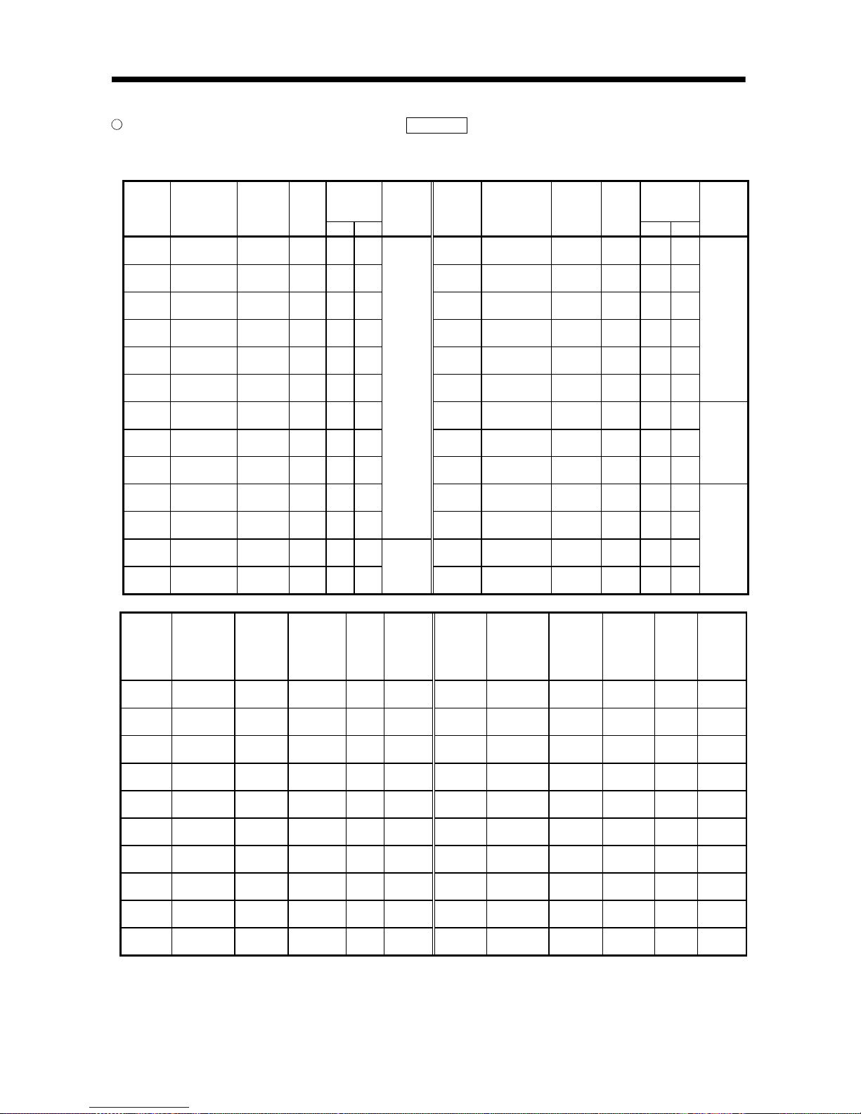
AT343A and AT543A mounting dimension tables Reference (Dimension unit: mm)
The following tables indicate L0 to L4 and number of mounting blocks or number of fixing holes in the
outline drawings shown on the next page.
Mounting
Block Fixing
Pitch
Mounting
Block Fixing
Pitch
Model
Effective
Measurement
Length
L0
Maximum
Moving
Length
L1
Full
Length
L2
L3 L4
Number of
Mounting
Blocks
(pcs.)
Model
Effective
Measurement
Length
L0
Maximum
Moving
Length
L1
Full
Length
L2
L3 L4
Number of
Mounting
Blocks
(pcs.)
AT343A-
300
300 330 440 220 150
AT343A-
1300
1300 1360 1470 735 325
AT343A-
350
350 380 490 245 175
AT343A-
1400
1400 1460 1570 785 350
AT343A-
400
400 430 540 270 200
AT343A-
1500
1500 1560 1670 835 375
AT343A-
450
450 480 590 295 225
AT343A-
1600
1600 1690 1800 900 400
AT343A-
500
500 540 650 325 250
AT343A-
1700
1700 1790 1900 950 425
AT343A-
600
600 650 760 380 300
AT343A-
1800
1800 1890 2000 1000 450
5
AT343A-
700
700 760 870 435 350
AT343A-
2000
2000 2100 2210 1105 335
AT343A-
750
750 810 920 460 375
AT343A-
2200
2200 2300 2410 1205 370
AT343A-
800
800 860 970 485 400
AT343A-
2400
2400 2500 2610 1305 400
7
AT343A-
900
900 960 1070 535 450
AT343A-
2500
2500 2600 2710 1355 315
AT343A-
1000
1000 1060 1170 585 500
3
AT343A-
2600
2600 2700 2810 1405 325
AT343A-
1100
1100 1160 1270 635 275
AT343A-
2800
2800 2900 3010 1505 350
AT343A-
1200
1200 1260 1370 685 300
5
AT343A-
3000
3000 3050 3210 1605 375
9
Model
Effective
Measurement
Length
L0
Maximum
Moving
Length
L1
Mounting
Hole Position
L2
Full
Length
L3
Number of
Fixing
Holes
(n) (pcs.)
Model
Effective
Measurement
Length
L0
Maximum
Moving
Length
L1
Mounting
Hole
Position
L2
Full
Length
L3
Number of
Fixing
Holes
(n)
(pcs.)
AT543A-
100
100 120 12.5 225 3
AT543A-
700
700 720 12.5 825 9
AT543A-
150
150 170 37.5 275 3
AT543A-
750
750 770 37.5 875 9
AT543A-
200
200 220 12.5 325 4
AT543A-
800
800 820 12.5 925 10
AT543A-
250
250 270 37.5 375 4
AT543A-
900
900 920 12.5 1025 11
AT543A-
300
300 320 12.5 425 5
AT543A-
1000
1000 1020 12.5 1125 12
AT543A-
350
350 370 37.5 475 5
AT543A-
1100
1100 1120 12.5 1225 13
AT543A-
400
400 420 12.5 525 6
AT543A-
1200
1200 1220 12.5 1325 14
AT543A-
450
450 470 37.5 575 6
AT543A-
1300
1300 1320 12.5 1425 15
AT543A-
500
500 520 12.5 625 7
AT543A-
1400
1400 1420 12.5 1525 16
AT543A-
600
600 620 12.5 725 8
AT543A-
1500
1500 1520 12.5 1625 17
2 - 4
2. LINEAR SCALES
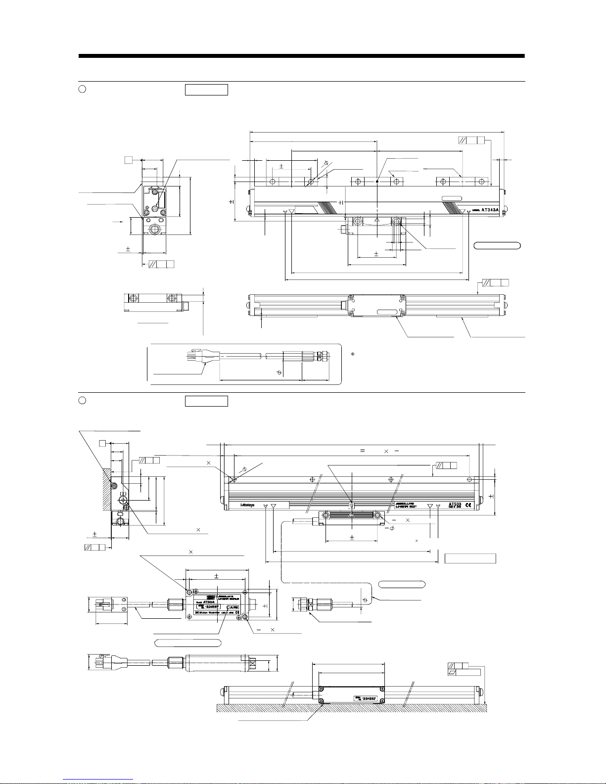
AT343A outline drawing Reference (Dimension unit: mm)
Effective measurement length 300mm to 3000mm
This outline drawing is based on the data from Mitutoyo. Contact Mitutoyo for this outline drawing.
Spot facing
depth 5
7
7
11.6
A
32.5
23
X
36
29
50.5 15
95.5
0.1
A
2.5
7.5
807
1
5
0.2
G
(42)
8
12.6
L
(
0.5
)
Scale body mounting
surface
Detection head
mounting surface
Air supply port (M5)
(Provided at both ends)
Full length L2
Mounting block fixing pitch L3
Mounting block fixing pitch L4 Mounting block fixing pitch L4
Elastical ly fixing
area
Mounting block
Completely
fixing area
Elastically
fixing area
Spot facing
depth 6.5
G: Machine guide
Effective measurement length L0
Maximum moving lengt h L1
View X
11 (hexagon)
Detection head
mounting surface
Scale body mounting
surface
Option (L = any of three different len gths, 0.2m, 2m, 3m)
Signal cable
(Vinyl sheathed)
( 16)
1.5 0.2
66 0.3
60 0.2
60 0.2
90
2
8
The signal cable is optional.
(Part No.09BAA598A to C: 0.2m, 2m, 3m)
1.5 0.2
0.2 G
AT543A outline drawing Reference (Dimension unit: mm)
This outline drawing is based on the data from Mitutoyo. Contact Mitutoyo for this outline drawing.
Air supply port (M5 0.8)
A
0.1
G
8.5
30
43
62
(1.5)
0.1
G
4
(17)
40
4.5
80
4.5
(40)
(
19.2
)
(19.6)
20
13.4
92
84
0.1
G
0.03/100
AR
Scale unit mounting surface
(Provided on both sides)
Mounting hole position: L2
(4.8)
Fixing screw: M4 0.8
(L = 18mm or more)
Full length: L3
(4.8)
Mounting hole pitch P 100mm (n 1)
Position where absolute value data is zero
(Nearly at scale center)
2 8 spot facing
depth 5(One side only)
2 M6 1
(through)
60 0.2
Fixing screw: M4 0.8L = 20mm or more,
or can be fixed with M6 screw from rear side.
Effective measurement length: L0
Maximum moving length: L1
G: Machine guide
Fixing screw: M4 0.8L = 18mm or more,
or can be fixed with M6 screw from rear side.
Output cable
(Vinyl sheath)
Alarm display LED window
Waterproof connector
2 M6 1
(through)
Scale uni t
Head cable
(Vinyl sheath)
Interface unit
Scale unit mounting surface
22
0.1
A
1 0.1
n
5
(
H
ol
e)
45.2 0.2
23
14
15.5
71 0.2
31 0.2
6.5
2 - 5
2. LINEAR SCALES
Connection cable connection examples (1)
The following cable wiring examples assume that the linear scale is connected directly to CN2 of the servo
amplifier.
(1) Connection example of up to 5m wiring length (This connection example assumes that the following
operating combination is satisfied.)
[Operating combination]
Used Wire Size Scale Model Scale Side Output Cable Specifications
AWG24 AT343A Mitutoyo make output cable 2m
AWG24 AT543A Mitutoyo make output cable 1m
[Connection example]
10120-3000PE, 10320-52F0- 008
(3M make or equi valent )
(Note 1)
Mitutoyo make linear scale
19
12
20
11
7
17
1
P5
LG
P5
LG
M
R
MR
R
LG
6
16
Plate
M
D
MD
R
S
D
P5
LG
R
Q
/
RQ
P5
LG
F
G
(Note 2)
CN2
Servo motor
Encoder
(Note 3)
Servo ampli fier
MR-J2S -
B
-PY096/S096
50m or less (2 wire type)
5m or less
Note 1. Do not connect the linear scale that is not indicated in this specification.
2. Connect the shield wire to the plate (ground plate) in the connector securely.
3. For the wiring to the servo motor, refer to the standard connection examples in Chapter 3 and the Instruction Manual of the MR-
J2S-
B standard model.
4. Contact the scale manufacturer for detailed specifications such as the combinations, models, types, etc. of the linear scale side
output cable and connector.
[Linear scale side connector] (Note 4)
Applicable
Housing
172161-9
(Tyco Electronics
or equivalent)
RDAD-15S-LNA
(Hirose Electric
or equivalent)
RQ 1 7
/RQ 2 8
P5 ( 5V) 7 3, 4
LG (0V) 8 1, 2
FG 9 15
2 - 6
2. LINEAR SCALES
(2) Connection example of 5m to 30m wiring length (This connection example assumes that the following
operating combination is satisfied.)
[Operating combination]
Used Wire Size Scale Model Scale Side Output Cable Specifications
AWG24 AT343A Mitutoyo make output cable 0.2m
AWG22 AT543A Mitutoyo make output cable 1m
[Connection example]
The wiring length is up to 30m. Depending on the wiring length, however, the number of LG and P5
connections must be changed according to the following table.
(Note 1)
Mitutoyo make linear scale
19
12
20
11
7
17
1
P5
LG
P5
LG
M
RMRR
LG
6
16
Plate
MD
MD
R
SD
P5
LG
RQ
/RQ
P5
LG
FG
(Note 2)
CN2
Servo motor
Encoder
(Note 3)
Servo amplifier
MR-J2S -
B
-PY096/S096
10120-3000PE, 10320-52F0-0 08
(3M make or equivalent )
50m or less (2 wire type)
30m or less
Note 1. Do not connect the linear scale that is not indicated in this specification.
2. Connect the shield wire to the plate (ground plate) in the connector securely.
3. For the wiring to the servo motor, refer to the standard connection examples in Chapter 3 and the Instruction Manual of the MR-
J2S-
B standard model.
4. Contact the scale manufacturer for detailed specifications such as the combinations, models, types, etc. of the linear scale side
output cable and connector.
Wiring
Length
Number of LG and
P5 Connections
to 5m 2 parallel
to 10m 4 parallel
to 15m 6 parallel
to 20m 8 parallel
to 25m 10 parallel
to 30m 12 parallel
[Linear scale side connector] (Note 4)
Applicable
Housing
172161-9
(Tyco Electronics
or equivalent)
RDAD-15S-LNA
(Hirose Electric or
equivalent)
RQ 1 7
/RQ 2 8
P5 ( 5V) 7 3, 4
LG (0V) 8 1, 2
FG 9 15
2 - 7
2. LINEAR SCALES
Connection cable connection examples (2)
The following cable wiring examples assume that the linear scale is connected to CN2 of the servo
amplifier using the option cable MR-J2SCLCBL02M-P-H.
(1) Connection example of up to 5m wiring length (This connection example assumes that the following
operating combination is satisfied.)
[Operating combination]
Used Wire Size Scale Model Scale Side Output Cable Specifications
AWG24 AT343A Mitutoyo make output cable 2m
AWG24 AT543A Mitutoyo make output cable 1m
[Connection example]
10120-3000PE, 10320-52F0- 008
(3M or equivalent)
To CN2
Servo motor
Encoder
(Note 1)
Mitutoyo make linear scale
1912P5
LG
7
17
20
11
Plate
M
R
MR
R
P5
LG
S
D
P5
LG
R
Q
/RQ
P5
LG
FG
(Note 2)
(Note 3)
Servo amplifier
MR-J 2S-
B
-PY096/S096
Linear
scale
connector
Option cable
(MR-J2SCLCBL02M-P-H)
5m or less
Note 1. Do not connect the linear scale that is not indicated in this specification.
2. Connect the shield wire to the plate (ground plate) in the connector securely.
3. For the wiring to the servo motor, refer to the standard connection examples in Chapter 3 and the Instruction Manual of the MR-
J2S-
B standard model.
4. Contact the scale manufacturer for detailed specifications such as the combinations, models, types, etc. of the linear scale side
output cable and connector.
5. When the MR-J2SCLCBL02M-P-H is used, the Mitsubishi option cable can be used as the linear scale connection cable.
Scale Model
Scale Side Output
Cable Length
Mitsubishi Option Cable
Model
0.2m MR-JCCBL2, 5, 10M-H
2m MR-JCCBL2, 5M-H
AT343A
3m MR-JCCBL2M-H
AT543A 1m MR-JCCBL2, 5, 10M-H
[Linear scale side connector] (Note 4)
Applicable
Housing
172161-9
(Tyco Electronics
or equivalent)
(Note 5)
RDAD-15S-LNA
(Hirose Electric or
equivalent)
RQ 1 7
/RQ 2 8
P5 ( 5V) 7 3, 4
LG (0V) 8 1, 2
FG 9 15
2 - 8
2. LINEAR SCALES
(2) Connection example of 5m to 30m wiring length (This connection example assumes that the following
operating combination is satisfied.)
[Operating combination]
Used Wire Size Scale Model Scale Side Output Cable Specifications
AWG24 AT343A Mitutoyo make output cable 0.2m
AWG22 AT543A Mitutoyo make output cable 1m
[Connection example]
The wiring length is up to 30m. Depending on the wiring length, however, the number of LG and P5
connections must be changed according to the following table.
10120-3000PE, 10320-52F0-008
(3M or equi valent)
To CN2
Servo mot or
Encoder
(Note 1)
Mitutoyo make linear scale
1912P
5LG7
17
20
11
Plat e
M
RMRRP5
LG
SD
P
5
LG
R
Q
/
RQ
P
5
LG
FG
(Note 2)
(Note 3)
Servo ampli fier
MR- J2 S-
B
-PY096/ S096
Linear
scale
connect or
Opti on cabl e
(MR-J2SCLCBL02M-P-H)
30m or less
Note 1. Do not connect the linear scale that is not indicated in this specification.
2. Connect the shield wire to the plate (ground plate) in the connector securely.
3. For the wiring to the servo motor, refer to the standard connection examples in Chapter 3 and the Instruction Manual of the MRJ2S-
B standard model.
4. Contact the scale manufacturer for detailed specifications such as the combinations, models, types, etc. of the linear scale side
output cable and connector.
5. When the MR-J2SCLCBL02M-P-H is used, the Mitsubishi option cable can be used as the linear scale connection cable.
Scale Model Scale Side Output Cable Length Mitsubishi Option Cable Model
0.2m MR-JCCBL2, 5, 10M-H
2m MR-JCCBL2, 5M-H
AT343A
3m MR-JCCBL2M-H
AT543A 1m MR-JCCBL2, 5, 10M-H
[Linear scale side connector] (Note 4)
Applicable
Housing
172161-9
(Tyco Electronics
or equivalent)
(Note 5)
RDAD-15S-LNA
(Hirose Electric or
equivalent)
RQ 1 7
/RQ 2 8
P5 ( 5V) 7 3, 4
LG (0V) 8 1, 2
FG 9 15
Wiring
Length
Number of LG
and P5
Connections
to 5m
2 parallel
to 10m
4 parallel
to 15m
6 parallel
to 20m
8 parallel
to 25m
10 parallel
to 30m
12 parallel
2 - 9
2. LINEAR SCALES
2.1.2 Heidenhain make linear encoder (linear scale) (ABS type) Scheduled to be compatible
Specifications Reference Scheduled to be compatible
Contact Heidenhain for the specifications of this linear encoder (linear scale).
Heidenhain Sales Section No. 2: TEL. (03) 3234-7781
Item Specifications
Model LC491M
System Photoelectric scanning system
Effective measurement length 70 to 2040mm
Resolution 0.05 m
Accuracy grade (20 )
5 m
3 m (up to effective measurement length 1240)
Supply power voltage 5V 5% on the linear encoder side
Current consumption Max.300mA
Rated response speed 2.0m/s
Maximum response speed 2.0m/s
Operating temperature range 0 to 50 (non-freezing) (Note 2)
Storage temperature range 20 to 70
(non-freezing)
Dust tightness water tightness
IP53 (when mounted according to the manual of the Heidenhain make linear encoder)
IP64 (when filled with compressed air)
Vibration resistance
100m/s
2
(DINIEC 68-2-6) without mounting spur
150m/s
2
(DINIEC 68-2-6) with mounting spur
Shock resistance 150m/s2 (DINIEC 68-2-6) (11ms)
Required feeding force 5N or less
Output signal Serial communication compatibility
Output cable 337 439 (17 pin coupling), 367 425 0 (20 pins), etc. (Note 1)
Connection cable Refer to the standard connection example in Chapter 3 and fabricate the cable.
Note 1. When the MR-J2SCLCBL02M-P-H is used, 367 425 (5m or less) can be connected directly.
2. The linear encoder (linear scale) is extremely sensitive to the operating temperature. When it exceeds 50
, an alarm may
occur. It is recommended to pay special attention to the operating temperature and secure the temperature change margins.
3. The battery (MR-BAT) is not required to configure an absolute position detection system.
Linear encoder (linear scale) unit structure Reference Scheduled to be compatible
Decreasing direction Increasing direction
(With the housing section fixed)
Home position

2 - 10
2. LINEAR SCALES
LC491M outline drawing Reference Scheduled to be compatible (Dimension unit: mm)
This outline drawing is based on the data from Heidenhain. Contact Heidenhain for this outline drawing.
DIN ISO 8015
ISO 2768-m H
2
Without mounting spur
With mounting spur
Machine gu ide
Measurement point for adjustment
Dimensional tolerance for machine installation
Compressed air filling port
Measurement length starting point (pos. 20mm)
Mounting s pur

2 - 11
2. LINEAR SCALES
Connection cable connection examples (1)
The following cable wiring examples assume that the linear encoder (linear scale) is connected directly to
CN2 of the servo amplifier.
CAUTION
When the Heidenhain linear encoder (linear scale) is used, the
communication system is of 4 wire type.
Change the setting of serial encoder cable selection (parameter No. 23) as
indicated below. If a wrong value is set, a servo alarm (alarm 70) occurs.
Pr.23
2 (4 wire type setting is made valid.)
(1) Connection example of up to 5m wiring length (This connection example assumes that the following
operating combination is satisfied.)
[Operating combination]
Used Wire Size Encoder (Scale) Model Encoder (Scale) Side Output Cable Specifications
AWG22 LC491M Heidenhain make output cable 0.5m
[Connection example]
(Note 1)
Heidenhain make linear encoder
(linear scale)
(Linear encoder head section)
19
12
20
11
7
17
1
P
5
LG
P
5
LG
M
RMRR
LG
4
14
6
16
Pla te
MD
2
MDR
2
MD
MD
R
SD
P5
LG
SD
/
SD
R
Q
/RQ
F
G
(Note 2)
CN2
Servo mot or
Encoder
(Note 3)
Servo ampli fier
MR- J 2S -
B
-PY096/ S096
5V/sensor
0V/sensor
10120-3000PE, 10320-52F0-008
(3M make or equi valent)
50m or less (2 wire type)
5m or less
Note 1. Do not connect the linear encoder (linear scale) that is not indicated in this specification.
2. Connect the shield wire to the plate (ground plate) in the connector securely.
3. For the wiring to the servo motor, refer to the standard connection examples in Chapter 3 and the Instruction Manual of
the MR-J2S-
B standard model.
4. Contact the scale manufacturer for detailed specifications such as the combinations, models, types, etc. of the linear
encoder (linear scale) side output cable and connector.
[Linear scale side connector] (Note 4)
Applicable
Housing
17 Pin Coupling
291697-26 (Female)
(Heidenhain make)
20 Pin Connector
(3M or equivalent)
SD 14 6
/SD 17 16
RQ 8 7
/RQ 9 17
5V 7 20
0V 10 1
5V/sensor 1 19
0V/sensor 4 11

2 - 12
2. LINEAR SCALES
(2) Connection example of 5m to 30m wiring length (This connection example assumes that the following
operating combination is satisfied.)
[Operating combination]
Used Wire Size Encoder (Scale) Model Encoder (Scale) Side Output Cable Specifications
AWG22 LC491M Heidenhain make output cable 0.5m
[Connection example]
The wiring length is up to 30m. Depending on the wiring length, however, the number of LG and P5
connections must be changed according to the following table.
19
12
20
11
7
17
1
P5
LG
P5
LG
M
RMRR
LG
Plate
SD
(Note 2)
CN2
Servo motor
Encoder
(Note 3)
Servo amplifier
MR-J 2S-
B
-PY096/S096
(Note 1)
Heidenhain make li near encoder (linear scale)
(Linear encoder head section)
P5
LG
SD
/
SD
R
Q
/RQ
5V/sensor
0V/sensor
FG
4
14
6
16
MD2
MDR2
MD
MD
R
10120-3000PE, 10320-52F0-008
(3M make or equivalent )
50m or less (2 wire type)
30m or less
Note 1. Do not connect the linear encoder (linear scale) that is not indicated in this specification.
2. Connect the shield wire to the plate (ground plate) in the connector securely.
3. For the wiring to the servo motor, refer to the standard connection examples in Chapter 3 and the Instruction Manual of the MR-
J2S-
B standard model.
4. Contact the scale manufacturer for detailed specifications such as the combinations, models, types, etc. of the linear encoder
(linear scale) side output cable and connector.
Wiring
Length
Number of LG and
P5 Connections
to 5m 2 parallel
to 10m 4 parallel
to 15m 6 parallel
to 20m 8 parallel
to 25m 10 parallel
to 30m 12 parallel
[Linear scale side connector] (Note 4)
Applicable
Housing
17 Pin Coupling
291697-26 (Female)
(Heidenhain make)
20 Pin Connector
(3M or equivalent)
SD 14 6
/SD
17 16
RQ 8 7
/RQ 9 17
5V 7 20
0V 10 1
5V/sensor 1 19
0V/sensor 4 11

2 - 13
2. LINEAR SCALES
Connection cable connection examples (2)
The following cable wiring examples assume that the linear encoder (linear scale) is connected to CN2 of
the servo amplifier using the option cable MR-J2SCLCBL02M-P-H.
(1) Connection example of up to 5m wiring length (This connection example assumes that the following
operating combination is satisfied.)
[Operating combination]
Used Wire Size Encoder (Scale) Model Encoder (Scale) Side Output Cable Specifications
AWG22 LC491M Heidenhain make output cable 0.5m
[Connection example]
10120-3000PE, 10320-52F0- 52F0-008
(3M or equivalent)
To CN2
Servo motor
Encoder
1912P5
LG
6
16
20
11
Plate
M
D
MD
R
P5
LG
S
D
(Note 2)
(Note 3)
Servo amplifier
MR-J2 S-
B
-PY096/S096
Linear
scale
connector
Option ca ble
(MR-J2SCLCBL02M-P-H)
(Note 1)
Heidenhain make linear encoder
(linear scale)
(Linear encoder head section)
P5
L
G
S
D
/
SD
R
Q
/
RQ
FG
5V/sensor
0V/sensor
717M
RMRR
5m or less
Note 1. Do not connect the linear encoder (linear scale) that is not indicated in this specification.
2. Connect the shield wire to the plate (ground plate) in the connector securely.
3. For the wiring to the servo motor, refer to the standard connection examples in Chapter 3 and the Instruction Manual of the MR-
J2S-
B standard model.
4. Contact the scale manufacturer for detailed specifications such as the combinations, models, types, etc. of the linear encoder
(linear scale) side output cable and connector.
5. Can be connected directly when the MR-J2SCLCBL02M-P-H is used.
[Linear scale side connector] (Note 4)
Applicable
Housing
17 Pin Coupling
291697-26 (Female)
(Heidenhain make)
20 Pin Connector
(Note 5)
(3M or equivalent)
SD 14 6
/SD 17 16
RQ 8 7
/RQ 9 17
5V 7 20
0V 10 1
5V/sensor 1 19
0V/sensor 4 11

2 - 14
2. LINEAR SCALES
(2) Connection example of 5m to 30m wiring length (This connection example assumes that the following
operating combination is satisfied.)
[Operating combination]
Used Wire Size Encoder (Scale) Model Encoder (Scale) Side Output Cable Specifications
AWG22 LC491M Heidenhain make output cable 0.5m
[Connection example]
The wiring length is up to 30m. Depending on the wiring length, however, the number of LG and P5
connections must be changed according to the following table.
10120-3000PE, 10320-52F0-008
(3M or equi valent)
To CN2
Servo motor
Encoder
1912P
5LG6
16
20
11
Pla te
MD
MD
R
P
5
LG
SD
(Note 2)
(Note 3)
Servo ampli fier
MR- J2 S-
B
-PY096/ S096
Linear
scale
connector
Opti on cabl e
(MR-J2SCLCBL02M-P-H)
(Note 1)
Heidenhain make linear encoder (linear sc ale)
(Linear encoder head section)
P
5
LG
SD
/
SD
R
Q
/
RQ
5V/sensor
0V/sensor
7
17
M
RMRR
FG
30m or less
Note 1. Do not connect the linear encoder (linear scale) that is not indicated in this specification.
2. Connect the shield wire to the plate (ground plate) in the connector securely.
3. For the wiring to the servo motor, refer to the standard connection examples in Chapter 3 and the Instruction Manual of the MRJ2S-
B standard model.
4. Contact the scale manufacturer for detailed specifications such as the combinations, models, types, etc. of the linear encoder
(linear scale) side output cable and connector.
5. Can be connected directly when the MR-J2SCLCBL02M-P-H is used.
Wiring
Length
Number of LG and
P5 Connections
to 5m 2 parallel
to 10m 4 parallel
to 15m 6 parallel
to 20m 8 parallel
to 25m 10 parallel
to 30m 12 parallel
[Linear scale side connector] (Note 4)
Applicable
Housing
17 Pin Coupling
291697-26 (Female)
(Heidenhain make)
20 Pin Connector
(Note 5)
(3M or equivalent)
SD 14 6
/SD
17 16
RQ 8 7
/RQ 9 17
5V 7 20
0V 10 1
5V/sensor 1 19
0V/sensor 4 11

2 - 15
2. LINEAR SCALES
2.1.3 Renishaw make linear encoders (linear scales) (INC type)
Specifications Reference
Contact Renishaw for the specifications of these linear encoders (linear scales).
Renishaw Encoder Section: TEL. (03) 5332-6023
Item Specifications
Model RGH26P RGH26Q RGH26R
System Optical system
Effective measurement length Maximum length 70000mm
Resolution 5 m1m0.5m
Accuracy (20 ) 3 m/m (when compensation is made between two points)
Supply power voltage 5V 5%
Current consumption Max.230mA
Rated response speed (Note 1) 4.0m/s 3.2m/s 1.6m/s
Maximum response speed 5.0m/s 4.0m/s 2.0m/s
Operating temperature range 0 to 55 (non-freezing)
Operating humidity range 10 to 90%RH (non-condensing)
Storage temperature range 20 to 70 (non-freezing)
Dust tightness water tightness IP50
Vibration resistance 100m/s2 (55 to 2000HZ)
Shock resistance 1000m/s2 (1/2sin, 11ms)
Output signal
Serial communication compatibility
(Z phase data included, serial communication of reference mark data is also is made) (Note 3)
Output cable Renishaw make N-15 PIN Dtype Dtype plug (0.5m)
Connection cable Refer to the standard connection example in Chapter 3 and fabricate the cable.
Note 1. Use at the rated speed or less.
2. A limit switch signal cannot be imported directly to the servo amplifier. When using a limit switch, use a photocoupler for
isolation.
3. A home position return cannot be made if there is no encoder (scale) home position (reference mark). Always provide an
encoder (scale) home position (reference mark).
Linear encoder (linear scale) unit structure Reference
RENISHAW
RGH26
Increasing direction Decreasing direction
Note 1. Always set an encoder (scale) home position (reference mark).

2 - 16
2. LINEAR SCALES
RGH26P, RGH26Q, RGH26R outline drawing Reference (Dimension unit: mm)
This outline drawing is based on the data from Renishaw. Contact Renishaw for this outline drawing.
Reference mark actuator
Dynamic bending radius R50
Static bending radius R10
6 minimum
Reference mark sensor position
Optical center
M3 0.5, two 9.5 deep holes
14
(Yaw tolerance 0.5 )
0.38
Mounting
surface
Setup
LED
(Roll tolerance 1.0 )
0.13
Mounting surface
range
Selectable mounting
surface
Q limit sensor position
M3 0.5, two 7.5
deep holes
Mount the Q
limit switch with
the white point up.
P limit sensor position
P limit switch
Mount it with the white point
directed toward the machine
stock side.
(Size is the same as that of
the Q limit switch.)
The arrow indicates the
forward moving direction
of the read head relative
to the scale.
Scale mounting surface
Clearance detail
(Pitch tolerance 1.0 )
0.8
0.8 0.1
7.6
27
13
9
3
11.6
16
17
15.5
6
10.5
10
3
23.5
14.614.6
44
38
10.6
5
2.2
4.7
7
14.5
22
4
2
3

2 - 17
2. LINEAR SCALES
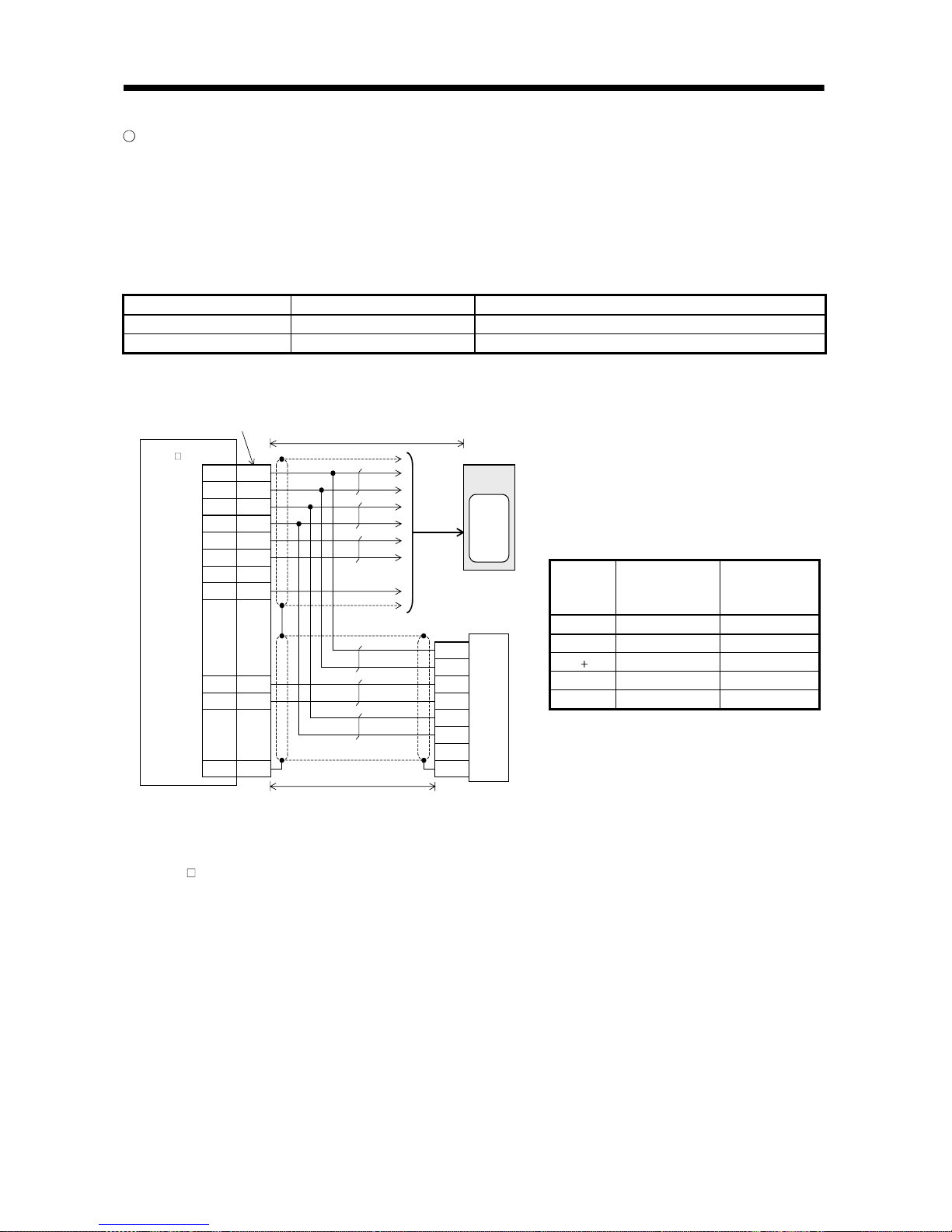
Connection cable connection examples (1)
The following cable wiring examples assume that the linear encoder (linear scale) is connected directly to
CN2 of the servo amplifier.
(1) Connection example of up to 5m wiring length (This connection example assumes that the following
operating combination is satisfied.)
[Operating combination]
Used Wire Size Encoder (Scale) Model Encoder (Scale) Side Output Cable Specifications
AWG22 RGH26 Renishaw make output cable 0.5m
[Connection example]
(Note 1)
Renishaw make linear encoder
(linear scale)
19
12
20
11
7
17
1
P5
LG
P5
LG
M
RMRR
LG
6
16
Plate
M
DMDR
S
D
P5
LG
M
RMRR
P5
LG
Inner
S
D
(Note 2)
CN2
Servo motor
Encoder
(Note 3)
Servo ampli fier
MR-J2S -
B
-PY096/S096
/P
/Q
Limit s witch out put (Note 4)
(Note 5)
10120-3000PE, 10320-52F0- 008
(3M make or equi valent)
50m or less (2 wire type)
5m or less
Note 1. Do not connect the linear encoder (linear scale) that is not indicated in this specification.
2. Connect the shield wire to the plate (ground plate) in the connector securely.
3. For the wiring to the servo motor, refer to the standard connection examples in Chapter 3 and the Instruction Manual of the MRJ2S-
B standard model.
4. A limit switch signal cannot be imported directly to the servo amplifier. When using a limit switch, use a photocoupler for
isolation as shown above. Contact the scale manufacturer for detailed specifications of the limit switch.
5. The encoder (scale) home position (reference mark) data is sent to the servo amplifier by serial communication.
6. Contact the scale manufacturer for detailed specifications such as the combinations, models, types, etc. of the linear encoder
(linear scale) side output cable and connector.
/P, /Q
5V
0V
Renishaw make
linear encoder (linear scale)
Photocoupler
isolation
[Linear encoder side connector] (Note 6)
Applicable
Housing
D Sub 15 Pin Female
Equivalent
Inner 15
P5 7, 8
LG 2, 9
MR 10
MRR 1
SD Case

2 - 18
2. LINEAR SCALES
(2) Connection example of 5m to 30m wiring length (This connection example assumes that the following
operating combination is satisfied.)
[Operating combination]
Used Wire Size Encoder (Scale) Model Encoder (Scale) Side Output Cable Specifications
AWG22 RGH26 Renishaw make output cable 0.5m
[Connection example]
The wiring length is up to 30m. Depending on the wiring length, however, the number of LG and P5
connections must be changed according to the following table.
19
12
20
11
7
17
1
P5
LG
P5
LG
M
R
MR
R
LG
6
16
Plate
MD
MD
R
SD
(Note 2)
CN2
Servo motor
Encoder
(Note 3)
Servo amplifier
MR-J2S -
B
-PY096/S096
(Note 1)
Renishaw make linear encoder
(linear scale) (Note 5)
P5
LG
M
R
MR
R
P5
LG
Inner
SD
/P/Q
(Note 5)
Limit switch outp ut (Note 4)
10120-3000PE, 10320-52F0-0 08
(3M make or equivalent )
50m or less (2 wire type)
30m or less
Note 1. Do not connect the linear encoder (linear scale) that is not indicated in this specification.
2. Connect the shield wire to the plate (ground plate) in the connector securely.
3. For the wiring to the servo motor, refer to the standard connection examples in Chapter 3 and the Instruction Manual of the MR-
J2S-
B standard model.
4. A limit switch signal cannot be imported directly to the servo amplifier. When using a limit switch, use a photocoupler for
isolation as shown above. Contact the scale manufacturer for detailed specifications of the limit switch.
5. The encoder (scale) home position (reference mark) data is sent to the servo amplifier by serial communication.
6. Contact the scale manufacturer for detailed specifications such as the combinations, models, types, etc. of the linear encoder
(linear scale) side output cable and connector.
Wiring
Length
Number of LG and P5
Connections
to 5m 2 parallel
to 10m 3 parallel
to 15m 4 parallel
to 20m 5 parallel
to 25m 6 parallel
to 30m 7 parallel
/P, /Q
5V
0V
Renishaw make
linear encoder (linear scale)
Photocoupler
isolation
[Linear encoder side connector] (Note 6)
Applicable
Housing
D Sub 15 Pin Female
Equivalent
Inner 15
P5 7, 8
LG 2, 9
MR 10
MRR 1
SD Case

2 - 19
2. LINEAR SCALES
Connection cable connection examples (2)
The following cable wiring examples assume that the linear encoder (linear scale) is connected to CN2 of
the servo amplifier using the option cable MR-J2SCLCBL02M-P-H.
(1) Connection example of up to 5m wiring length (This connection example assumes that the following
operating combination is satisfied.)
[Operating combination]
Used Wire Size Encoder (Scale) Model Encoder (Scale) Side Output Cable Specifications
AWG22 RGH26 Renishaw make output cable 0.5m
[Connection example]
10120-3000PE, 10320-52F0- 008
(3M or equivalent)
To CN2
Servo motor
Encoder
1912P5
LG
7
17
20
11
Plate
M
R
MR
R
P5
LG
S
D
(Note 2)
(Note 3)
Servo amplifier
MR-J 2S-
B
-PY096/S096
Linear
scale
connector
Option ca ble
(MR-J2SCLCBL02M-P-H)
(Note 1)
Renishaw make linear encoder
(linear scale)
P5
L
GMR
MR
R
P5
L
G
Inner
S
D
/
P
/
Q
(Note 5)
Limit switch output (Note 4)
5m or less
Note 1. Do not connect the linear encoder (linear scale) that is not indicated in this specification.
2. Connect the shield wire to the plate (ground plate) in the connector securely.
3. For the wiring to the servo motor, refer to the standard connection examples in Chapter 3 and the Instruction Manual of the MRJ2S-
B standard model.
4. A limit switch signal cannot be imported directly to the servo amplifier. When using a limit switch, use a photocoupler for
isolation as shown above. Contact the scale manufacturer for detailed specifications of the limit switch.
5. The encoder (scale) home position (reference mark) data is sent to the servo amplifier by serial communication.
6. Contact the scale manufacturer for detailed specifications such as the combinations, models, types, etc. of the linear encoder
(linear scale) side output cable and connector.
[Linear encoder side connector] (Note 6)
Applicable
Housing
D Sub 15 Pin Female
Equivalent
Inner 15
P5 7, 8
LG 2, 9
MR 10
MRR 1
SD Case
/P, /Q
5V
0V
Renishaw make
linear encoder (linear scale)
Photocoupler
isolation

2 - 20
2. LINEAR SCALES
(2) Connection example of 5m to 30m wiring length (This connection example assumes that the following
operating combination is satisfied.)
[Operating combination]
Used Wire Size Encoder (Scale) Model Encoder (Scale) Side Output Cable Specifications
AWG22 RGH26 Renishaw make output cable 0.5m
[Connection example]
The wiring length is up to 30m. Depending on the wiring length, however, the number of LG and P5
connections must be changed according to the following table.
10120-3000PE, 10320-52F0-008
(3M or equivalent )
To CN2
Servo motor
Encoder
1912P
5
LG
7
17
20
11
Pla te
M
RMRRP5
LG
SD
(Note 2)
(Note 3)
Servo ampli fier
MR- J2 S-
B
-PY096/ S096
Linear
scale
connect or
Opti on cabl e
(MR-J2 SCLCBL02H-P-H)
(Note 1)
Renishaw make linear encoder (linear scale)
P
5
LG
M
RMRRP5
LG
Inner
SD
/
P
/
Q
(Note 5)
Limit swit ch out put (Note 4)
30m or less
Note 1. Do not connect the linear encoder (linear scale) that is not indicated in this specification.
2. Connect the shield wire to the plate (ground plate) in the connector securely.
3. For the wiring to the servo motor, refer to the standard connection examples in Chapter 3 and the Instruction Manual of the MRJ2S-
B standard model.
4. A limit switch signal cannot be imported directly to the servo amplifier. When using a limit switch, use a photocoupler for
isolation as shown above. Contact the scale manufacturer for detailed specifications of the limit switch.
5. The encoder (scale) home position (reference mark) data is sent to the servo amplifier by serial communication.
6. Contact the scale manufacturer for detailed specifications such as the combinations, models, types, etc. of the linear encoder
(linear scale) side output cable and connector.
Wiring
Length
Number of LG and
P5 Connections
to 5m 2 parallel
to 10m 3 parallel
tob15m 4 parallel
to 20m 5 parallel
to 25m 6 parallel
to 30m 7 parallel
[Linear encoder side connector] (Note 6)
Applicable
Housing
D Sub 15 Pin Female
Equivalent
Inner 15
P5 7, 8
LG 2, 9
MR 10
MRR 1
SD Case
/P, /Q
5V
0V
Renishaw make
linear encoder (linear scale)
Photocoupler
isolation

2 - 21
2. LINEAR SCALES
2.1.4 Sony precision technology make linear encoders (linear scales) (INC type)
Specifications Reference
Contact Sony Precision Technology for the specifications of these linear encoders (linear scales).
Sony Precision Technology Sales Section: TEL. (03) 3490-3915
Item Specifications
Interpolator model MJ830
Linear encoder model SL710 PL101R (H)
System Magnetic detection system
Effective measurement length 50 to 3000mm
Resolution Min. 0.2 m (Note 2)
Accuracy 10 m
Supply power voltage 5V (4.5 to 5.5V) (Note 1)
Power consumption Max.3W
Rated response speed 6.4 m/s
Maximum response speed 6.4 m/s
Operating temperature range 0 to 55
(non-freezing) 0 to 45
(non-freezing)
Storage temperature range 20 to 65 (non-freezing) 20 to 50 (non-freezing)
Dust tightness water tightness No protective structure IP50 (PL101R), IP64 (PL101RH)
Vibration resistance 9.6m/s2 5 to 800Hz 20m/s2 50 to 2000Hz
Shock resistance 980m/s2 11ms 980m/s2 11ms
Output signal Serial communication compatibility (Z phase data included)
Output extension cable CK-T1
Connection cable
Refer to the standard connection example
in Chapter 3 and fabricate the cable.
Item Specifications
Interpolator model MJ830
Linear encoder model SH13
System Optical detection system
Effective measurement length 70 to 1240mm
Resolution Min. 0.005 m (Note 2)
Accuracy
3 m A3 type
5 m A5 type
Supply power voltage 5V (4.5 to 5.5V) (Note 1)
Power consumption Max. 3W
Rated response speed 1.4m/s
Maximum response speed 2.0m/s
Operating temperature range 0 to 55 (non-freezing) 0 to 45 (non-freezing)
Storage temperature range 20 to 65 (non-freezing) 10 to 60 (non-freezing)
Dust tightness water tightness No protective structure
IP53
(in accordance with the mounting in the
manual of the Sony Precision Technology make
linear encoder)
Vibration resistance 9.6m/s2 5 to 800Hz 98m/s2 (30 to 1000Hz, 30 minutes)
Shock resistance 980m/s2 11ms
294m/s
2
(11ms, three directions XYZ,
three times each)
Output signal Serial communication compatibility (Z phase data included) (Note 3)
Output extension cable CR4-05NNT0 , CR4-10NNT01 (10m)
Connection cable
Refer to the standard connection example
in Chapter 3 and fabricate the cable.
Note 1. For the 24V-specified interpolator, contact Sony Precision Technology.
2. Changes depending on the setting of the interpolator.
3. A home position return cannot be made if there is no encoder (scale) home position (reference mark). Always provide an
encoder (scale) home position (reference mark).

2 - 22
2. LINEAR SCALES
Linear encoder (linear scale) unit structure Reference
[When interpolator (MJ830) MODE switch = 5]
When PL101 or SL700 is used
SONY SL700
SONY
PL101R
Increasing direction Decreasing direction
When SH13 is used
Decreasing direction Increasing direction
SH13
Note 1. Note that the increasing direction/decreasing direction of the linear encoder (linear scale) changes depending on the setting of
the interpolator (MJ830).
2. Always set an encoder (scale) home position (reference mark).

2 - 23
2. LINEAR SCALES
SL710 outline drawing Reference (Dimension unit: mm)
This outline drawing is based on the data from Sony Precision Technology. Contact Sony Precision
Technology for this outline drawing.
SL710
Mount the scale on a non-magnetic material.
When mounting it on a magnetic material, provide
a non-magnetic layer of 3mm or more.
n - D reamed hole
(For D parallel pin insertion)
P (n - 1 or 2)
Effective measurement length (ML)
Full length = effective measurement length + 40
(20)
20
D/2
P 200
12 0.05
25
9
ML - P (n - 1)
200
PL101 outline drawing Reference (Dimension unit: mm)
This outline drawing is based on the data from Sony Precision Technology. Contact Sony Precision
Technology for this outline drawing.
<PL101-RH (IP67 type)>
Offset
Effective measurement length (ML)
Full length = effective measurement length + 40
Clearance
2 2 - M3 depth 5
43.5
Pitch
Roll
Cable length: 3000mm
48
Center mark
<PL101-N/PL101-R (IP50 type)>
Offset
Effective measurement length (ML)
Full length = effective measurement length + 40
Cable length: 3000mm
Roll
Pitch
Center mark
43.5
2 2 - M3 depth 5
11.5 48
1.5
0.15
12
6
0.15
Clearance
12
6
20 20(20) (20)
25
9
12 0.2
12 0.2
9
25
SH13 outline drawing Reference (Dimension unit: mm)
This outline drawing is based on the data from Sony Precision Technology. Contact Sony Precision
Technology for this outline drawing.
SONY
SH13-
124
1240
2
450
434
620
114
1140
2
420
394
570
102
1020
2
380
354
510
092
920
1
507
460
082
820
1
457
410
077
770
1
432
385
072
720
1
407
360
067
670
1
382
335
062
620
1
357
310
057
570
1
332
285
052
520
1
307
260
047
470
235
042
420
210
037
370
185
032
320
160
027
270
135
022
220
110
017
170
85
012
120
60
007
70
35
L
n
A
P1
Z
mm
mm
mm
mm
Scale full length = L + 105
Scale mounting hole pitch = L + 94
Middle support mounting
position = A
Middle support mounting
position = A
(n - 1) P1
Middle support A
Middle support B
Home position mark
Head cable length = 1000
(20)
12
Scanning unit
2
12
56
80
40 Z
4
8
4.6
26.513
Home position
Effective measurement length = L
Left side measurement end
Right side measurement end
M4 (depth 10)
3
3374
M4 (depth 10)
12
36
4.5
20
2 - 5, 8.2 spot facing
depth 5
Air intake (M5)
(5.5)
Depth 5
Middle support B mounting side face
Middle support A mounting side face
21
10.5
10
5
22
556
6
1915
26
43.5
7.5
13
2.5 0.3
Effective measurement length
Middle support
Middle support mounting
hole pitch
Home position
5.5
35
26
(25)
43.5
5
19
5.8

2 - 24
2. LINEAR SCALES
MJ830 outline drawing Reference (Dimension unit: mm)
This outline drawing is based on the data from Sony Precision Technology. Contact Sony Precision
Technology for this outline drawing.
4.5 mounting hole
26
13
(13)
3
4.5
93
100
(115)
138
124
1

2 - 25
2. LINEAR SCALES
Connection cable connection example (1)
The following cable wiring example assumes that the linear encoder (linear scale) is connected directly to
CN2 of the servo amplifier.
(1) Connection example of up to 30m wiring length (This connection example assumes that the following
operating combination is satisfied.)
[Operating combination]
Used Wire Size Interpolator Model
AWG28 MJ830
[Connection example]
(Note 1)
Sony Precision
Technology make
interpolator
19
12
20
11
7
17
1
P5
LG
P5
LG
M
R
MR
R
LG
6
16
Plate
M
DMDRSD
LG
LG
M
RMRR
SHD
(Note 2)
CN2
Servo motor
Encoder
(Note 3)
Servo amplifier
MR-J2S -
B
-PY096/S096
Sony Precision Technology make
linear encoder (linear scale)
Stabilized
power s upply
(5V)
10120-3000PE, 10320-52F0- 008
(3M make or equi valent)
50m or less (2 wire type)
30m or less
Note 1. Do not connect the linear encoder (linear scale) that is not indicated in this specification.
2. Connect the shield wire to the plate (ground plate) in the connector securely.
3. For the wiring to the servo motor, refer to the standard connection examples in Chapter 3 and the Instruction Manual of the MR-
J2S-
B standard model.
4. Contact the scale manufacturer for detailed specifications such as the combinations, models, types, etc. of the linear encoder
(linear scale) side output cable and connector.
[Linear encoder side connector] (Note 4)
Applicable
Housing
10114-3000PE, 10314-52F0-008
3M or Equivalent
OV 11, 12
MR 4
MRR 5
SHD 7

2 - 26
2. LINEAR SCALES
Connection cable connection example (2)
The following cable wiring example assumes that the linear encoder (linear scale) is connected to CN2 of
the servo amplifier using the option cable MR-J2SCLCBL02M-P-H.
(1) Connection example of up to 30m wiring length (This connection example assumes that the following
operating combination is satisfied.)
[Operating combination]
Used Wire Size Interpolator Model
AWG28 MJ830
[Connection example]
10120-3000PE, 10320-52F0- 008
(3M make or equi valent)
To CN2
Servo motor
Encoder
1211LG
LG
7
17
Plate
M
R
MR
RSD
(Note 2)
(Note 3)
Servo amplifier
MR-J 2S-
B
-PY096/S096
Linear
scale
connector
Option cable
(MR-J2SCLCBL02M-P-H)
(Note 1)
Sony Precision
Technology make
interpolator
LG
LG
M
R
MR
RSHD
Sony Precision Technology make
linear enco der (linea r scale)
Stabi li zed
power supply
(5V)
30m or less
Note 1. Do not connect the linear encoder (linear scale) that is not indicated in this specification.
2. Connect the shield wire to the plate (ground plate) in the connector securely.
3. For the wiring to the servo motor, refer to the standard connection examples in Chapter 3 and the Instruction Manual of the MR-
J2S-
B standard model.
4. Contact the scale manufacturer for detailed specifications such as the combinations, models, types, etc. of the linear encoder
(linear scale) side output cable and connector.
[Linear encoder side connector] (Note 4)
Applicable
Housing
10114-3000PE, 10314-52F0-008
3M or Equivalent
OV 11, 12
MR 4
MRR 5
SHD 7

2 - 27
2. LINEAR SCALES
2.2 A B Z-phase differential input interface unit specifications
Contact the linear scale manufacturer for the specifications of the A/B/Z-phase differential output linear
scale. (Since the permissible resolution range is 0.005 to 5
m, select the linear scale within this range.)
Specifications
Item Description
Model MR-J2S-CLP01
Permissible
voltage
fluctuation
DC4.85 to 5.25V
Power
supply
Current
consumption
200mA (when power is supplied from servo amplifier)
250mA (when power is supplied from external power supply) (Note 1)
Input signal A B Z-phase differential input signal
Minimum phase
difference
500ns
Output signal High-speed serial communication (Z phase data included)
Structure Open (IP00)
Ambient
temperature
0 to 55 (non-freezing)
Storage
temperature
20 to 65 (non-freezing)
Ambient
humidity
90%RH or less (non-condensing)
Storage
humidity
90%RH or less (non-condensing)
Ambience
Indoors (no direct sunlight)
Without corrosive gas, flammable gas, oil mist, dust and dirt
Altitude 1000m or less above sea level
Environment
Vibration 5.9m/s2 or less
Weight 0.4kg
Note 1. The power supply of the linear scale is not included. When an external power supply is used, an up to 350mA linear
scale can be used.

2 - 28
2. LINEAR SCALES
MR-J2S-CLP01 outline drawing
[Unit: mm]
6 hole
Terminal layout
Model Weight [kg]
(75) 90
1.6
6
156
168
R
3
TE1
P5L
P50
MR-J2S-CLP01
0.4

2 - 29
2. LINEAR SCALES
Connection cable connection example
Note 1. The A/B/Z-phase differential input interface unit is required to use the A B Z-phase differential output linear scale.
2. If there is no Z phase, an alarm occurs and operation cannot be performed.
3. If there is no alarm output, change the setting of the following servo amplifier parameter.
Pr.62
0
4. The A-phase, B-phase, Z-phase and alarm signals must be provided as differential line driver outputs.
5. Set the internal setting switch (SW1) to CLOSE.
6. If the current consumption of the linear scale exceeds 150mA, supply external power.
7. Connect the shield wire to the plate (ground plate) in the connector securely.
8. Use a cable that can endure bending motion for a long time.
9. Because of RS-422 communication, the cable length is maximum 30m. However, it may be necessary to shorten the length
depending on the power supply voltage drop and linear scale specifications.
10. As the connection cable, use the MR-J2HBUS05M or MR-J2HBUS1M.
11. When a connection cable is to be fabricated, the cable length should be within 1m.
A
B Z-phase
differential input
interface unit
MR-J2S-CLP01
(Note 7)
Servo
amplifier
MR-J2S-
CN2
1
19
7
17
11
20
Plate
LG
P5
MR
MRR
LG
P5
SD
LG
P5
MR
MRR
LG
P5
SD
CN2
1
19
7
17
11
20
Plate
10120-3000PE, 10320-52F0-008
(3M make or equivalent)
A/B/Z-phase differential output linear
Connection cable (Note10,11)
MR-J2HBUS05M or MR-J2HBUS1M
10114-3000PE, 10314-52F0-008
(3M make or equivalent)
P5L
LG
LA
LAR
LB
LBR
LZ
LZR
(LAL)
(LALR)
SD
CN1A
14
1
2
3
4
5
6
7
8
9
Plate
5V
0V
A
phase
(Note 4)
B phase
(Note 4)
Z phase
(Note 2, 4)
(Alarm)
(Note 3, 4)
Shield
(Note 7)
(Note 1, 5)
(Note 6)
(Note 8, 9)
P5L
P5G
PE
(
Note 6
)
LA, LB, LZ, LAL
LAR, LBR, LZR, LALR
A
M26LS31 o
r
equivalent
Linear scale
LALR
LAL
LZR
LZ
LBR
LB
LAR
LA
Phase difference 500ns or
1 pulse of Z phase = 1 cycle of A phase
1
s or more at alarm occurrence
LINEAR
CLOSE
SW1

2 - 30
2. LINEAR SCALES
MEMO

3 - 1
3. SIGNALS AND WIRING
3 SIGNALS AND WIRING
3.1 Standard connection examples of full closed control servo amplifier control signals
(1) When MR-J2S-CLP01 is used
24VDC
Note
1. Use the MR-J2HBUS M-A or MR-J2HBUS M cable within the overall
length of 30m. To improve noise immunity, it is recommended to use a
cable clamp and data line filters (connect 3 or 4 pcs. in series) near the
connector lead-out area.
2. The motor side connections of the second axis and later are omitted.
3. Up to eight axes (n = 0 to 7) can be connected.
The MR-H BN type servo can also be connected to the same bus.
(Note that the cable differs.)
4. In this example, the motor is equipped with an electromagnetic brake.
The power supply connected to the electromagnetic brake is irrelevant
to the polarity. The HC-SFS121 to 301, 202 to 702, 203, 353 and
HC-UFS202 to 502 use different connectors.
5. Connect the shield wire to the plate (ground plate) in the connector
securely.
6. Connect the diode in the correct orientation. If it is connected oppositely,
the amplifier will fail and signals will not be output.
7. A forced stop of the corresponding axis servo amplifier alone.
Use it as necessary when the QD75M, Q172, Q173 or Position Board is
connected. Do not use it when any of the A171SH, A172SH, A173UH
and A273UH is connected.
When this signal is not used, short EM1-SG within the connector.
Make an emergency stop of the whole system on the controller side.
A forced stop input can be made invalid using parameter No. 23.
8. For details, refer to the "MR-J2S-B Instruction Manual" and
"MR-J2S-CLP01 Installation Guide".
9. Always use a shielded multi-core cable. Up to 15m is allowed in noise free environment. However, the cable length should be within 3m when
38,400bps or more baud rate is set for RS-232C communication.
10. When using an external power supply, do not connect VDD-COM.
11. When the personal computer is connected simultaneously with analog
monitor output 1 (MO1) or analog monitor output 2 (MO2), use the
maintenance relay card (MR-J2CN3TM).
12. CN1A, CN1B, CN2 and CN3 have the same shape. Incorrect
connection of the connector can cause a failure.
13. In the case of single-phase 100VAC (MR-J2S-40B1-PY096 or less) or
single-phase 230VAC (MR-J2S-70B-PY096 or less), connect the
power suppl y to the L
1
, L2 terminals and keep L3 open.
G
H
7
6
8
9
5
4
14
2
3
LZ
LZR
LAL
LALR
SD
LB
R
LB
P5L
LAR
LA
CN1 A
CLOSE
CN1B
1LG
7
8
1
2
4
5
9
P5
LG
MR
MRR
MD
M
DR
S
D
3
BAT
6
CNT
B1
B2
Z
S
R
C
D
A
B
F
G
N
M
24VDC
A
B
C
D
EM1
L1
L2
L3
C
P
N
TE1
L11
L21
B1
B2
5
6
Z
RA1
1
2
3
4
L
11
L
21
L
1
L
2
L
3
TE1
TE2
P
C
D
CN3
12
2
1
11
Rx
LG
LG
Tx
RD
SD
GND
GN
D
R
S
-
232C
CS1
0
MO1
LG
M
O
2
LG
4
1
14
11
E
MG
20
EM
1
3
SG
RA1
13
MBR
5COM
10
VD
D
SD
LA
6
16
LA
R
7
LB
LBR
17
LZ
8
LZR
18
CS1
1
8
1
2
4
5
9
P
5
LG
MR
MRR
M
D
MD
R
SD
3
B
AT
6CNT
7
6
8
9
5
4
14
2
3
LZ
LZR
LAL
LALR
SD
LBR
LB
P5L
LAR
LA
CN1 A
1LG
MR
-
J2S-C
LP01
7
RA
1
CN1B
CS
1
Configure a sequence that will turn off
MC at an alarm or emergency stop.
MC
NFB
Power supply
Three-phase 200 to
230VAC or single-phase
100VAC/single-phase
230VAC (Note 13)
If the regenerative option is
connected incorrectly, the servo
amplifier is damaged.
In the case of MR-J2S-500B/700B
Configure a sequence that will
turn off MC at an alarm or
emergency stop.
Servo amplifier
MR-J2S- B-S096
Regenerative
option
When connecting an external
regenerative option, always
disconnect the link from across C-P.
Regenerative
option
When connecting an external
regenerative option, always
disconnect the link from
across P-D.
Controller
A171SH
A172SH
A173UH
A273UH
QD75M
Q172
Q173
Position Board
Cable
clamp
Use the MR-J2HBUS M-A cable with the
A171SH,A172SH, A173UH or A273UH, and
the MR-J2HBUS M cable with the QD75M.
(Note 1)
Refer to the "Motion Controller Q Series Catalog"
for the cable between Q172/Q173 and amplifier,
and to the "Position Board, Interface Board New
Product News (SV0206-1)" for the cable between
Positi on Board and ampl ifier.
MR-J2HBUS M cable
MR-J2HBUS M cable
Always insert the terminating
connector (MR-A-TM) to the
termination of the servo bus.
Servo amplifie r
MR-J2S- B
-PY096/-S096
(Axis 1)
(Note 12)
CN2
CN1A
(Note 12)
Plate
CN1B
(Note 12)
Servo amplifier
MR-J2S- B
(-PY096/-S096)
(Axis 2)
CN1A
(Note 12)
CN1B
(Note 2)
(Note 2)
CN1A
(Note 12)
CN1B
Servo amplifier
MR-J2S- B
(-PY096/-S096)
(Axis n)
Set SW1 to
CLOSE.
(Note 3)
CN2
(Note 12)
MR-J2HBUS M
cable
Use 1m or less .
A B Z-phase differential
input interface unit
MR-J2S-CLP01
Plate
(Note 12)
(Note 12)
Shut off when servo-on
signal turns off or alarm
signal turns on.
Motor
HC-KFS, MFS,
UFS3000r/min series
(Note 4)
SM
Electromagnetic
brake
Encoder
General-purpose
linear scale or
rotary encoder
(A B Z-phase
differential output
type)
Connect the MR-HP4CN1
connector to the CN1A
connector.
(Note 8)
MR-JCCBL M-H cable or
MR-JCCBL M-L cable
Use 30m or less.
15m or less
(Note 9)
Commercially available
personal computer
Windows
(Note 7)
Forced stop
10m or less
(Note 6)
Electromagnetic
brake interlock
(Note 10) When not using the external power supply,
always connect VDD-COM.
Max. +1mA meter
Zero-center ( 10V output)
A
A
Monitor output 1
(Note 11)
Monitor output 2
10k
10k
Encoder A-phase pulse
(Differential line driver)
Encoder B-phase pulse
(Differential line driver)
Encoder Z-phase pulse
(Differential line driver)
2m or less
Plate
(Note 12)
Shut off when serv o-on
signal turns off or al arm
signal turns on.
Motor
HC-SFS, RFS,
UFS2000r/min series
SM
(Note 4)
Electromagnetic
brake
Encoder
General-purpose
linear scale or
rotary encoder
(A/B/Z-phase
differential output
type)
Connect the MR-HP4CN1
connector to the CN1A
connector.
MR-JHSCBL M-H cable,
MR-JHSCBL M -L cable
or MR-ENCBL M-H cable
Use 30m or less.
(Note 8)
U
V
W
A
EM1
n - 1
U
V
W
U
V
W
MR-J2S- B
-PY096/-S096
NFB MC
U
V
W
D
D

3 - 2
3. SIGNALS AND WIRING
(2) When serial communication compatible linear scale is connected to closed end F/B
P5
CN2
LG
P5
LG
MR
M
RR
19
MRR
10
MR
S
D
17
P5
7
11
12
20
1
P5
LG
P5
LG
LG
18
P5
2
LG
LG
M
D
2
MDR2
MD
MDR
BAT
6
16
9
4
14
SD
SD
19
MRR
18
M
R
17
P
5
7
2
12
1
20
LG
P
5
LG
P5
LG
11 LG
M
D6
MD
R
16
BAT
9
S
R
C
D
A
B
F
G
N
M
19
MRR
10
MR
SD
17
P5
7
11
12
20
1
P
5
LG
P5
LG
LG
18
P5
2
L
G
19
MRR
MR
SD
17
P5
7
11
12
20
1
P5
LG
LG
LG
18
P5
2 LG
CN1 A
CN1 B
CN3
7
8
1
2
4
5
9
P5
LG
MR
MRR
M
D
M
DR
SD
3
BAT
6CN
T
8
1
2
4
5
9
P5
LG
MR
MRR
MD
M
DR
S
D
3
B
AT
6CNT
7
17
19
12
20
11
1
7
19
MRR
MR
S
D
17
P
5
7
11
12
20
1
P5
LG
LG
LG
18
P
5
2
L
G
20
11
17
19
7
P5
SD
LG
MRR
MR
P5
12 LG
17
12
7
SD
M
RR
MR
LG
11 LG
SHD
M
RR
MR
0V
0V
P5
FG
LG
/RQ
RQ
P5
LG
20
11
17
19
7
P5
SD
LG
MRR
MR
P5
12 LG
P5
/P
LG
MRR
MR
P5
LG
/Q
17
7
16
19
6
MRR
SD
M
R
MD
R
MD
P5
12 LG
/RQ
RQ
/SD
SD
5V
0V
FG
11 LG
20 P5
CN2
5m
30m
5
m
CaseSD
For connection of TE1, TE2
and connectors CN1A,
CN1B, CN3, refer to "3.1
(1) When MR-J2S-CLP01 is
used".
Using the ABS type scale
enables an absolute position
detection system to be
configured. At that time,
the battery (MR-BAT) is not
needed.
Servo amplifier
MR-J2S- B
-PY096/-S096
Plate
Plate
Motor connector
MR-JCCBL M-H cable or
MR-JCCBL M-L cable
Use 30m or less.
Motor connector
Motor
HC-KFS, MFS,
UFS3000r/min series
Encoder
Encoder
Plate
MR-JHSCBL M -H cable,
MR-JHSCBL M -L cable or
MR-ENCBL M-H cable
Use 30m or less.
Motor
HC-SFS, RFS,
UFS2000r/min series
Linear scale
connector
Plate
(Note1)
(Note2)
(Note6)
(Note6)
(Note7)
(Note7)
(Note3)
(Note7)
(Note4, 7)
5
m
(Note6)
Mitutoyo make
linear scale
Sony Precision Technology
make interpolator
Sony Precision Technology
make linear encoder (linear scale)
Stabilized
power
supply
(5V)
Renishaw make linear encoder
(linear scale)
Heidenhain make linear
encoder (linear scale)
Limit switch output
0V/sensor
5V/sensor
The Heidenhain make linear scale is compatible
with the MR-J2S-B-PY096/-S096 type only .
The option cable (MR-J2SCLCBL02M-P-H) can be used for
connection between CN2 and motor connector or between
CN2 and linear scale connector.
For CN2
Amplif ier con nector
(3M or equivalent)
10120-3000PE (connector)
10320-52F0-008 (shell kit)
(Note 5)
For motor
Motor connector (3M or equivalent)
10220-0200EL (connector)
10320-E2W0-008 (shell kit)
Linear scale connector (3M or equivalent)
10220-0200EL (connector)
10320-E2W0-008 (shell kit)
(Note 5)
For linear scale
motor
SCALE
Note 1. Fabricate the linear scale connection cable on the customer side using the optional CN1 connector (MR-J2CN1).
2. Cont act the corresponding scale manufacturer for the linear scale and interpolator side pin numbers.
3. For the specifications of the stabilized power supply, contact Sony Precision Technology.
4. To use the Heidenhain make linear scale, the parameter No. 23 (in the case of the MR-J2S-B-PY096/-S096 type) setting
must be chan ged. Refer to "CHAPTER 2 LIN EAR SCALES" for mo re information.
5. The motor connector and linear scale connector have the same shape. Incorrect connection of the connector can cause a failure.
6. Th is wiring is for AWG22. Up to 30m is allowed by changin g the wiring.
Refer to " CHAPTER 2 LINEAR SCALES " for details of wiring.
7. Use a fter confirming the specifications of the linear scale s uch as the temperatures, vibration resistance and protective str ucture.
For use in the environment having much static noise, contact the scale manufacturer separately.
Plate
Plate
Plate
Plate
(Note1)
(Note2)
(Note2)
(Note1)
(Note2)
(Note1)
inner
0.2m
Plate
Plate

3 - 3
3. SIGNALS AND WIRING
(3) When serial communication compatible servo motor is connected to closed end F/B
P5
CN2
LG
P5
LG
MR
MRR
19
M
RR
10
MR
SD
17
P5
7
11
12
20
1
P5
LG
P5
LG
LG
18
P5
2
LG
LG
MD
2
MDR
2
MD
M
DR
BAT
6
16
9
4
14
SD
19
MR
R
18
MR
17
P5
7
2
12
1
20
L
G
P
5
LG
P
5
LG
11L
G
MD6
MD
R
16
BAT9
SD
SD
19
MRR
18
MR
17
P5
7
2
12
1
20
LG
P
5
LG
P5
LG
11
LG
M
D
6
M
DR
16
BAT
9
7
8
1
2
4
5
9
P
5
LG
MR
MR
R
M
D
MDR
SD
3
BAT
6
CNT
8
1
2
4
5
9
P
5
LG
M
R
MRR
MD
M
D
R
S
D
3
BAT
6
CNT
7
S
R
C
D
A
B
F
G
N
M
19
MR
R
10
MR
SD
17
P5
7
11
12
20
1
P5
LG
P5
LG
LG
18
P
5
2
LG
19
MRR
MR
S
D
17
P5
7
11
12
20
1
P5
LG
LG
LG
18
P
5
2
LG
CN1 A
CN1 B
CN3
7
8
1
2
4
5
9
P5
LG
MR
MR
R
MD
MD
R
SD
3
BAT
6CNT
8
1
2
4
5
9
P
5
LG
M
R
MR
R
M
D
MDR
S
D
3
BAT
6
CNT
7
7
17
19
12
20
11
1
19
MRR
MR
SD
17
P
5
7
11
12
20
1
P5
LG
LG
L
G
18
P
5
2
LG
CN2
For connection of TE1, TE2
and connectors CN1A,
CN1B, CN3, refer to "3.1
(1) When MR-J2S-CLP01 is
used".
Servo amplifier
MR-J2S- B
-PY096/-S096
Plate Plate
Motor conn ector
MR-JCCBL M-H cable or
MR-JCCBL M-L cable
Use 30m or less.
Plate
Plate
Motor conn ector
MR-JHSCBL M -H cable,
MR-JHSCBL M -L cable or
MR-ENCBL M-H cable
Use 30m or less.
Drive motor
HC-KFS, MFS,
UFS3000r/min series
Drive motor
HC-SFS, RFS,
UFS2000r/min series
EncoderEncoder
Position detection
motor
HC-KFS, MFS series
Encoder
Position detector connector
MR-JCCBL M-H cable or
MR-JCCBL M-L cable
Use 30m or less.
Plate
Plate
Plate
(Note1)
(Note1)
The option cable (MR-J2SCLCBL02M-P-H) can be used for
connection between CN2 and motor connector or between
CN2 and linear scale connector.
For CN2
Amplifier connector
(3M or equivalent)
10120-3000VE (connector)
10320-52F0-008 (shell kit)
(Note 2)
For motor
Motor connector (3M or equivalent)
10220-0200EL (connector)
10320-E2W0-008 (shell kit)
Linear scale connector (3M or equivalent)
10220-0200EL (connector)
10320-E2W0-008 (shell kit)
(Note 2)
For position detector
motor
SCALE
Note 1. Fabricate the linear scale connection cable on the customer side using the optional CN1 connector (MR-J2CWired in the option cable
(MR-J2SCLCBL02M-P-H). Note that it is not compatible with an absolute position detection system .
2. The motor connector and position detector connector have the same shape. Incorrect connection of the connector can cause a failure.
0.2m

3 - 4
3. SIGNALS AND WIRING
(4) About CN2 wiring for closed end serial communication compatibility (when MR-J2CLCBL02M-P-H is used)
For use of the serial I/F compatible encoder, the wiring diagram shows that a bifurcated cable is to be
connected. When using the option cable MR-J2CLCBL02M-P-H in the bifurcated wiring area, perform
wiring as shown below.
(a) For serial communication compatible linear scale
Servo amplifier
CN2
Encoder signal
Linear scale
3) Serial communication signal cabl
e
Servo motor
1) MR-J2SCLCBL02M-P-H
2)
1) Use the MR-J2SCLCBL02M-P-H.
(Refer to "CHAPTER 7 OPTIONS AND AUXILIARY EQUIPMENT" for details such as internal
connection.)
2) Use the encoder cable (e.g. MR-JCCBL
M-H, MR-JHSCBL M-H, MR-ENCBL M-H) of the
servo motor.
3) The wiring method changes depending on the linear scale.
Confirm "CHAPTER 2 LINEAR SCALES" and fabricate a connection cable on the customer side.
(b) For serial communication compatible rotary encoder
Servo amplifier
CN2
Encoder signal
Closed end servo motor
for detection
2) Encoder signal
Drive servo motor
1) MR-J2SCLCBL02M-P-H
2) (Note 2)
1) Use the MR-J2SCLCBL02M-P-H.
(Refer to " CHAPTER 7 OPTIONS AND AUXILIARY EQUIPMENT " for details such as
internal connection.)
2) Use the encoder cable (e.g. MR-JCCBL
M-H, MR-JHSCBL M-H, MR-ENCBL M-H) of the
servo motor.

3 - 5
3. SIGNALS AND WIRING
3.2 Signal
t
erminal explanation
(1) Main circuit terminal block, control circuit terminal block
Signal Name Abbreviation
Termina
l Block
Description
Main circuit
power supply
L1, L2, L3 TE1
Main circuit power input terminals.
MR-J2S- B : Connect three-phase 200 to 230VAC/50, 60Hz.
MR-J2S-
B1 : Connect single-phase 100 to 120VAC/50, 60Hz.
Servo motor
output
U, V, W TE1
Servo motor power output terminals.
Connect to the servo motor power supply terminals (U, V, W). During
power-on, do not open or close the motor power line. Otherwise, a
malfunction or faulty may occur.
Control
circuit power
supply
L11, L21 TE2
Control circuit power input terminals.
L11 should be in the same power supply phase with L1, and L21 with L2.
MR-J2S- B : Connect to single-phase 200 to 230VAC/50, 60Hz.
MR-J2S-
B1 : Connect to single-phase 100 to 120VAC/50, 60Hz.
Regenerative
option
P, C, D TE2
Regenerative option connection terminals.
Factory-wired across P-D.
When using the regenerative option, always remove the wire across P-D
and connect the regenerative option across P-C.
N
Keep open.
Protective
earth
PE Chassis
Ground terminal.
Connect to the earth terminal of the servo motor and the protective earth of
the control box for grounding.
(2) CN3
Signal Name Abbreviation Pin No.
Function/Application
Digital I/F power
supply input
COM 5
24VDC for input interface is input.
Digital interface driver power input terminal.
COM is all connected internally.
When using an external power supply, connect a power supply of 24VDC
and 200mA or more instead of VDD.
I/F internal
power supply
output
VDD 10
Digital interface driver power output terminal.
24VDC is output across VDD-SG. Connect with COM.
(Do not make connection when using an external power supply.)
The permissible current is 80mA.
Digital I/F
common
SG 3
24V common for VDD/COM and isolated from LG.
Control common LG 1, 11
Control common used as a monitor common.
LA 6
Encoder
A-phase pulse
LAR 16
Encoder A-phase pulse output terminals.
The pulses set in parameter No. 38 (ENR) in the output type selected in
parameter No. 68 (FC2) are output in the differential line driver system.
LB 7
Encoder
B-phase pulse
LBR 17
Encoder B-phase pulse output terminals.
The pulses set in parameter No. 38 (ENR) in the output type selected in
parameter No. 68 (FC2) are output in the differential line driver system.
LZ 8
Encoder
Z-phase pulse
LZR 18
Encoder Z-phase pulse output terminals.
1 pulse is output per servo motor revolution.
By setting parameter No. 68 (FC2), the Z phase (reference mark) of the full
closed encoder can be output.
MO1 4
Monitor output
MO2 14
Monitor output signal output terminals.
The data set in parameter No. 22 (MOD) is output in analog form.
The multiplying factor can be set in parameter No. 22 (MOD).
Electromagnetic
brake interlock
MBR 13
MBR-SG are disconnected at servo-off or alarm. At alarm occurrence, they
are disconnected independently of the base circuit state.
Forced stop EM1 20
When EM1-SG are opened, a forced stop state occurs, the servo switches
off, and the dynamic brake is operated to make a stop. The forced stop
signal can be made invalid using parameter No. 23.
Shield SD Plate
Connect one end of the shield wire.

3 - 6
3. SIGNALS AND WIRING
3.3 About power-on
The servo amplifier can accept a servo-on command within about 5s after the main circuit is powered on.
Therefore, when SON is turned on as soon as the main circuit is powered on, the base circuit switches on
within about 5s to make operation ready.
[Timing chart]
Within 5s
SON acceptance
Power supply
Base circuit
ON
OFF
ON
OFF
Servo-on command
(From controller)
ON
OFF
60ms
10ms

4 - 1
4. OPERATION AND FUNCTIONS
4 OPERATION AND FUNCTIONS
4.1 Startup
4.1.1 Startup procedure
Start up the full closed control system in the following procedure.
Completion of installation and wiring
Positioning operation check by controller
Refer to Section 4.1.3.
Refer to Section 4.1.4.
Adjustment and operation check in full closed control
Refer to Section 4.1.7.
Refer to Section 4.1.5.
Refer to Section 4.3.
Refer to Section 4.1.2.
Adjustment and operation check in semi closed control
Positioning operation check using MR Configurator
Selection of full closed function
Gain adjustment
Selection of full closed encoder communication system
Setting of full closed encoder electronic gear
Setting of full closed encoder polarity
Positioning operation check using MR Configurator
Home position return operation
Positioning operation
Gain adjustment
Adjustment of dual F/B switching filter (for dual F/B control)
Completion of full closed control system startup
Refer to Section 4.2.
Check that the servo
equipment is normal.
Do as necessary.
Refer to Section 4.1.6.
Confirmation of full closed encoder position data

4 - 2
4. OPERATION AND FUNCTIONS
4.1.2 Selection of full closed function
(1) Parameters
No. Abbreviation Name and Function
Initial
Value
Unit
Setting
Range
62 FCT Full closed selection:
Select the full closed encoder direction, full closed
control error detection function 1 and full closed control
error detection function 2.
Full closed function
0: Invalid
1: Always valid
2: Switching valid (semi/full
switching by host controller)
1300 0000h
to
1312h
67 DUF Dual F/B filter
Set the bandwidth of the dual F/B filter.
At 1000rad/s setting, the full closed control is made
always valid.
At 0rad/s setting, the full closed control is made
invalid.
About half of the position loop gain 2 in parameter No.
15 is the guideline of the upper setting limit.
10 rad/s 0
to
1000
Note 1. When changing the setting of the above parameter, set "000F" in parameter No. 40 "parameter block ( BLK)".
2. After setting the parameter marked
, switch power off once. The setting is made valid by switching power on again.
(2) Parameter setting method
Selection between semi closed control and full closed control can be made by combining the settings of
parameter No. 62 and No. 67.
Pr62 (FCT) Full Closed Function Pr67 (DUF) Control Mode
0 Invalid Semi closed control
0 to 999 Dual F/B full closed control
1 Valid
1000
Completely full closed control
When the full closed function switching is valid (semi/full switching by host controller), the
combinations are as follows.
At this time, the semi/full switching signal is invalid and semi closed control is performed in the test
operation from the MR Configurator.
Pr62 (FCT) Semi/Full Switching Signal Pr 67 (DUF) Control Mode
MR Configurator Test Operation
Mode
2
Semi selection
Semi closed control
1 to 999
Dual F/B full closed
control
2
Full selection
1000
Completely full closed
control
Semi closed control
CAUTION
Contact your sales representative for the models and specifications of the
host controller that allows semi/full switching.

4 - 3
4. OPERATION AND FUNCTIONS
4.1.3 Selection of full closed encoder communication system
(1) Parameters
No. Abbreviation Name and Function
Initial
Value
Unit
Setting
Range
23 OP1 Optional function 1:
Select the optional function 1.
0000 0000h
to
0201h
Note 1. After setting the parameter marked , switch power off once. The setting is made valid by switching power on again.
(2) Parameter setting method
The communication system changes depending on the full closed encoder type.
Refer to section 2.1 Compatible Linear Scale List for the communication systems of the full closed
encoders.
CAUTION
If a wrong value is set in Serial encoder cable selection (parameter No. 23),
a servo alarm (alarm 70) occurs at power-on of the servo amplifier.
Serial encoder cable selection
Select the communication systems of CH1 (for motor) and CH2 (for
full closed encoder).
When full closed func tion is invalid
(Pr:62: 0)
When full closed func tion is valid
(Pr:62: 1 or 2)
Hundreds digit
setting
ENC CH1 ENC CH2 ENC CH1 ENC CH2
0 2 wire type Unusable 2 wire type 2 wire type
1 4 wire type Unusable 4 wire type Unusable
2 2 wire type Unusable 2 wire type 4 wire type

4 - 4
4. OPERATION AND FUNCTIONS
4.1.4 Setting of full closed encoder polarity
(1) Parameter
No. Abbreviation Name and Function
Initial
Value
Unit
Setting
Range
62 FCT Full closed selection
Select the full closed encoder direction, full closed
control error detection function 1 and full closed control
error detection function 2.
Full closed encoder polarity
0: Scale increasing direction in motor CCW
direction
1: Scale increasing direction in motor CW
direction
1300 0000h
to
1312h
Note 1. When changing the setting of the above parameter, set "000F" in parameter No. 40 "parameter block ( BLK)".
2. After setting the parameter marked
, switch power off once. The setting is made valid by switching power on again.
(2) Parameter setting method
Make setting so that the CCW direction (forward rotation direction) of the servomotor matches the
increasing direction of the full closed encoder feedback.
This setting must be made for all linear scales or rotary encoders.
[Pr. 62 = 0 : When the encoder address increasing direction is set for motor CCW]
Linear scale
Servo motor
Motor CCW direction
Linear scale increasing direction
[Pr. 62 = 1 : When the encoder address increasing direction is set for motor CW]
Linear scale
Servo motor
Motor CCW direction
Linear scale increasing direction
(3) How to confirm the full closed encoder feedback direction
For the way to confirm the full closed encoder feedback direction, refer to "4.1.6 Confirmation of full
closed encoder position data".
CAUTION
If a wrong value is set in the encoder direction of the full closed encoder
selection (parameter No. 62), normal operation may not performed, causing
machine collision. It may also cause a servo alarm (AL. 42) during
positioning operation.
The above full closed encoder polarity setting is irrelevant to Pr. 7 (POL)
"rotation direction selection". As described above, always make setting
according to the relationship between the servo motor and linear scale or
rotary encoder.

4 - 5
4. OPERATION AND FUNCTIONS
4.1.5 Setting of full closed encoder electronic gear
(1) Parameters
No. Abbreviation Name and Function
Initial
Value
Unit
Setting
Range
65 FCM Full closed electronic gear numerator
Set the numerator of the electronic gear relative to the
full closed encoder pulse.
11
to
65535
66 FCD Full closed electronic gear denominator
Set the denominator of the electronic gear relative to
the full closed encoder pulse.
11
to
65535
Note 1. When changing the setting of the above parameter, set "000F" in parameter No. 40 "parameter block ( BLK)".
2. After setting the parameter marked
, switch power off once. The setting is made valid by switching power on again.
(2) Parameter setting method
For the full closed electronic gear setting, set the ratio of the full closed encoder feedback to the servo
motor encoder feedback.
Make setting so that the full closed electronic gear
FCD
FCM
does not fall outside the
FCD
FCM1100
100
1
<<
range.
This setting must be made for all linear scales or rotary encoders.
[Setting example 1] When the servo motor is directly coupled with a ballscrew and the linear scale resolution is
0.05
m
Calculate the number of linear scale pulses per servo motor revolution.
[Setting example 2] When a rotary encoder at roll feed detection end is used for detection
When the pulley diameters or reduction ratios differ, consider that in calculation.
For the rotary encoder, make calculation using the number of pulses multiplied by 4.
CAUTION
If a wrong value is set in the linear scale electronic gear (parameter No. 65,
66), normal operation may not performed.
It may also cause a servo alarm (AL. 42) during positioning operation.
FCM
FCD
Number of servo motor encoder
p
ulses per servo
Number of full closed encoder pulses per servo
Servo motor
Linear scale
<Conditions>
Servo motor resolution : 131072pulse/rev
Ballscrew lead : 4mm
Linear scale resolution : 0.05
m
FCM
FCD
131072
80000
1024
625
Ballscrew lead / linear scale resolution
4mm/0.05 m 80000pluse
Servo motor
Pulley diameter d2 20mm
Pulley diameter d1 30mm
Rotary encoder
5000pulse/rev
<Conditions>
Servo motor resolution : 131072pulse/rev
Servo motor side pulley diameter : 30mm
Rotary encoder side pulley diameter : 20mm
Rotary encoder resolution : 5000pulse/rev
(20000 pulses/rev after multiplication by 4)
FCM
FCD
131072 20
20000 30
8192
1875

4 - 6
4. OPERATION AND FUNCTIONS
4.1.6 Confirmation of full closed encoder position data
Check the full closed encoder mounting and parameter settings for any problems.
POINT
Depending on the check items, the MR Configurator may be used.
Refer to "4.6 About Setup" for the data displayed on the MR Configurator.
[Check items]
When checking the following items, the full closed control mode must be selected by setting parameter
No. 62 and No. 67.
For the control mode setting, refer to "4.1.2 Selection of full closed function".
No. Check Item Checking Method/Description
1 Read of full closed encoder position data With the full closed encoder in a normal state (mounting,
connection, etc.), the cumulative feedback pulse 2 (full closed
encoder side) value is counted normally when the full closed
encoder is moved.
2 Read of full closed encoder scale home position
(reference mark, Z phase)
With the scale home position (reference mark, Z phase) of
the full closed encoder in a normal state (mounting,
connection, etc.), the within-full-one-revolution position (full
closed encoder side) value is cleared to 0 when the scale
home position (reference mark, Z phase) is passed through
by moving the full closed encoder.
3 Confirmation of full closed encoder feedback
direction
(Setting of full closed encoder polarity)
Confirm the full closed encoder feedback direction at the
within-full-one-revolution position (full closed encoder side) by
moving the device (full closed encoder) manually in a servo
off state.
When the servo motor and full closed encoder feedback
directions match, running the servo motor in the CCW
direction (counterclockwise as viewed from the shaft end)
increases the within-full-one-revolution position (full closed
encoder side), and running the servo motor in the CW
direction (clockwise as viewed from the shaft end) decreases
the within-full-one-revolution position (full closed encoder side).
When the servo motor and full closed encoder directions do
not match, operation is performed oppositely.
4 Setting of full closed electronic gear When the servo motor and full closed encoders operate
synchronously, the cumulative feedback pulse (motor encoder
side) and cumulative feedback pulse 2 (full closed encoder
side) values increase in accordance with the setting ratio of
the full closed electronic gear (FCM/FCD).
[Confirmation example]
When the servo motor is directly coupled with a ballscrew and the
linear scale resolution is 1.0
m
Motor encoder resolution
131072pullse/rev
Ballscrew lead
4.0mm
Linear scale resolution
1.0 m
When the movement is equivalent to one servo motor revolution
(machine end 4.0mm)
Cumulative feedback pulse 2 (full closed encoder side) 4000 pulses

4 - 7
4. OPERATION AND FUNCTIONS
4.1.7 Setting of dual feedback switching filter
(1) Parameter
No. Abbreviation Name and Function
Initial
Value
Unit
Setting
Range
67 DUF Dual F/B filter
Set the bandwidth of the dual F/B filter.
At 1000rad/s setting, the full closed control is made
always valid.
At 0rad/s setting, the full closed control is made invalid.
About half of the position loop gain 2 in parameter No.
15 is the guideline of the upper setting limit.
10 rad/s 0
to
1000
Note 1. When changing the setting of the above parameter, set "000F" in parameter No. 40 "parameter block ( BLK)".
(2) Parameter setting method
1) With the initial value (setting = 10) set in parameter No. 67, make gain adjustment by auto
tuning, etc. as in semi closed control.
2) While observing the servo operation waveform with the graph function, etc. of the MR
Configurator, adjust the dual F/B filter.
The dual F/B filter operates as described below depending on the setting.
No. 67 Setting
Smaller
1 (initial value = 10)
to
Larger
PG2 setting/2
1000
Control mode Dual F/B Full closed
Vibration Less likely to occur. More likely to occur.
Settling time Increases. Decreases.
Increasing the dual F/B filter setting shortens the settling time, but increases motor
vibration since the motor is more likely to be influenced by the full closed encoder vibration.
The maximum setting of the dual F/B filter should be less than half of the PG2 setting.
[Reduction of settling time]: Increase the dual F/B filter setting.
[Suppression of vibration]: Decrease the dual F/B filter setting.
Droop pulses
Time
Command
Droop pulses
Time
Command
Droop pulses
Droop pulses
Time
Command
Time
Command

4 - 8
4. OPERATION AND FUNCTIONS
4.2 Home position return operation
4.2.1 General precautions
Home position return operation is all performed according to the full closed encoder feedback data,
independently of the full closed encoder type. It is irrelevant to the Z-phase position of the motor encoder.
In the case of a home position return using a dog signal, the scale home position (reference mark) must be
passed through when an incremental type linear scale is used, or the Z phase be passed through when a
rotary encoder is used, during a period from a home position return start until the dog signal turns off.
4.2.2 Full closed encoder types and home position return methods
(1) About proximity dog type home position return using absolute linear scale Serial I/F
When an absolute linear scale is used, the home position reference position is the position per motor
encoder resolution relative to the scale home position (absolute position data = 0).
In the case of a proximity dog type home position return, the nearest position after proximity dog OFF
is the home position.
The scale home position may be set in any position.
Home position return speed
Creep speed
Home position return direction
Scale home position
Home position
return operation
Proximity dog
signal
Machine position
Home position
ON
OFF
Home position
reference position
Equivalent to one motor encoder revolution

4 - 9
4. OPERATION AND FUNCTIONS
(2) About proximity dog type home position return using incremental linear scale
Serial I/F
General-purpose pulse output
When an incremental linear scale is used, the home position is the position per motor encoder
resolution relative to the scale home position (reference mark) passed through first after a home
position return start.
In the case of a proximity dog type home position return, the nearest position after proximity dog OFF
is the home position.
Set one scale home position in the full stroke, and set it in the position that can always be passed
through after a home position return start.
If a home position return is started at the position where the scale home position (reference mark)
does not exist in the home position return direction, a home position return error occurs in the
controller (the error definition changes depending on the controller type). When starting a home
position return at the position where the scale home position (reference mark) does not exist in the
home position return direction, move the axis up to the stroke end on the side opposite to the home
position return direction by jog operation, etc. of the controller once, then make a home position
return.
CAUTION
To execute a home position return securely, start a home position return
after moving the axis to the opposite stroke end by jog operation, etc. of the
controller.
To execute a home position return securely, start a home position ret A
home position return cannot be made if the incremental linear scale does
not have a scale home position (reference mark). Always provide a scale
home position (reference mark). (One place in the full stroke)
Home position return speed
Creep speed
Home position return direction
Scale home position
Home position return
Proximity dog
signal
Machine position
Home position
ON
OFF
Home position
reference position
Equivalent to one motor encoder
revolution
Home position return speed
Creep speed
Home position return direction
Scale home position
Home position return
Proximity
dog
signal
Machine position
Home position
ON
OFF
Stroke end
Jog operation
Home position return enabled Home position return disabled area

4 - 10
4. OPERATION AND FUNCTIONS
[Precautions]
Note the following if the system uses the positioning module (QD75M) or VME bus Position Board (MR-MC01)
as a position controller.
The scale home position (reference mark) has some
width in the region where the signal turns on.
The signal ON width changes depending on the used linear scale.
Contact the scale manufacturer for details.
The positioning module (QD75M) or VME bus Position Board (MR-MC01) determines the home position
reference position when the scale home position (reference mark) is passed through first after power-on of
the servo amplifier. Therefore, a lag equivalent to the scale home position signal width is produced in the
home position reference position depending on the direction in which the scale home position (reference
mark) is passed through.
Therefore, when it is desired to always make a home position return to the same position without a lag
equivalent to the scale home position signal width, a home position return must be performed so that the
scale home position is always passed through in the same direction.
The following indicates a home position return method in which a lag equivalent to the scale home
position signal width is not produced in the positioning module (QD75M) or VME bus Position Board
(MR-MC01).
[Home position return method in which lag equivalent to scale home position signal width is not produced]
(a) Move the linear servo motor to the position where the stroke end signal on the side opposite to the
home position return direction turns on.
(b) Perform the power-on reset of the servo amplifier or reset the controller.
(c) Switch on the servo and make a home position return.
Scale home position
signal
ON
OFF
Signal ON width
Scale home position
ON
OFF
Signal ON width
Home position
reference position
(
Passed through
in direction)
Home position
reference position
(
Passed through
in direction
)
Lag equivalent to scale home position signal ON
width is produced.
Equivalent to one motor
encoder revolution
Equivalent to one motor
encoder revolution
Machine position
Stroke end
Scale home position Home position
Stroke end
Home position return direction
Creep speed
Home position return speed
Scale home position
Home position return operation
Proximity dog
signal
Machine position
Home position
ON
OFF

4 - 11
4. OPERATION AND FUNCTIONS
SUPPLEMENT
The positioning module (QD75M) and VME bus Position Board (MR-
MC01) are scheduled for modification to operate like the other
controllers.
Contact your sales representative for the modification time and
compatible versions.
CAUTION
The home position return retry function of the positioning module (QD75M)
cannot be used.

4 - 12
4. OPERATION AND FUNCTIONS
(3) About proximity dog type home position return using rotary encoder
Serial I/F
General-purpose pulse output
The home position using a rotary encoder as a full closed encoder is as described below. It is the
position per motor encoder resolution, starting at the position where the Z phase of the full closed
encoder is passed through first after power-on of the servo amplifier.
[Precautions]
Precautions for passage of Z phase
The home position reference position is set relative to the Z phase position of the full closed encoder
that is passed through first after power-on of the servo amplifier.
In Case A and Case B where the power-on position differs as shown below, the power-on position must
be noted since the axis cannot stop at the same home position return position.
Servo amplifier
power-on position
Machine position
Home position
Home position
reference position
Full closed
encoder Zphase signal
ON
OFF
Equivalent to one motor encoder revolution
Home position reference is position per
motor encoder resolution relative to Z-phase
signal of full closed encoder that was passed
through first after power-on of servo
amplifier.
Servo amplifier
power-on position
Home position
return
operation
Home position
Home position
reference
position
Full closed
encoder Zphase signal
ON
OFF
Equivalent to one motor encoder revolution
Home position return speed
Creep speed
Proximity dog
signal
ON
OFF
Servo amplifier
power-on position
Home position
return
operation
Home position
Home position
reference
position
Home position
return speed
Creep speed
Equivalent to one motor encoder revolution
Case
Case

4 - 13
4. OPERATION AND FUNCTIONS
[Method for always making home position return to the same position]
(a) Move the linear servo motor to the position where the stroke end signal on the side opposite to the
home position return direction turns on.
(b) Perform the power-on reset of the servo amplifier or reset the controller.
(c) Switch on the servo and make a home position return.
Machine position
Stroke end
Scale home position Home position
Stroke end
Home position return speed
Creep speed
Home position return direction
Scale home position
Home position return operation
Proximity dog
signal
Machine position
Home position
ON
OFF

4 - 14
4. OPERATION AND FUNCTIONS
(4) About data setting type count type 2) (QD75M) Common to all full closed encoders
In the data setting type/count type 2) (QD75M) home position return method, a home position return
can be normally made if the home position has been passed through (in either direction) before start of
a home position return, since a scale home position (reference mark) or the Z-phase signal of a rotary
encoder is not required.
When the linear scale used does not have a scale home position (reference mark) or the machine has
no distance of one motor encoder revolution until the Z phase of the rotary encoder is passed through,
a home position return can be made by changing the parameter (Pr. 33 "home position setting
condition selection") setting if the home position is not yet passed through.

4 - 15
4. OPERATION AND FUNCTIONS
4.3 Operation from controller
The full closed control compatible amplifier can be used with any of the following controllers.
Classification Model Remarks
A17 SHCPU, A173UHCPU
A273UHCPU (-S3)Motion controller
Q17
CPU
Speed control (II) instructions (VVF, VVR) cannot be used.
Positioning module QD75M
AD(A1SD)75M cannot be used.
Home position return must be made with care.
MR-MC10 (PCI bus compatible)
MR-MC2 (CPCI bus compatible)
MR-MC30 (ISA bus compatible)
Position Board
MR-MC01 (VME bus compatible) Home position return must be made with care.
Note. An ABS type linear scale is required to configure an absolute position system.
The battery (MR-BAT) need not be fitted to the servo amplifier.
4.3.1 Operation from controller
Positioning operation from the controller is basically performed like the standard model servo.
However, some parameter settings and home position return operation change depending on the
controller type.
4.3.2 Controller setting
When using full closed control, make the following setting.
Set the other servo parameters and control parameters as in the standard servo.
(1) Motion controller, positioning module
After writing parameter No. 23, 33, 62, 65, 66, and 68 to the servo amplifier, turn off the power supply
and then on again to make the setting valid. (For motion controller, resetting makes the servo
amplifier setting valid.)
Settings
Motion controller Positioning module
Setting Item
A17
SH, A173UH, A273UH
Q17
QD75M
Command resolution Motor encoder resolution unit
Amplifier setting MR-J2S- B
Motor setting Automatic setting
Serial encoder cable selection
(parameter No. 23)
Setting is necessary only when a 4
wire type linear scale is used.
Contact your sales representative
for the setting method.
Home position setting condition selection
(parameter No. 33)
Contact your sales representative
for the setting method.
Full closed selection (parameter No. 62)
Full closed control error detection 1 (parameter No. 63)
Full closed control error detection 2 (parameter No. 64)
Full closed electronic gear numerator
(parameter No. 65)
Full closed electronic gear denominator
(parameter No. 66)
Dual F/B filter (parameter No. 67)
Servo
parameters
Full closed selection 2 (parameter No. 68)
Set using
MR Configurator.
Set using sequence
ladder.
Unit setting mm/inch/degree/pulse
Positioning
control
parameters
Moving distance per pulse (AP, AL, AM)
Number of pulses per revolution (AP)
Moving distance per revolution (AL)
Unit multiplying factor (AM)
Set AP, AL and AM as usual with motor encoder
resolution.
SUPPLEMENT
In the future, the Q motion controller (Q17 ) is scheduled to allow the
servo parameter Pr. 40 to Pr. 75 settings to be changed from the
peripheral software.
Contact your sales representative for the modification time and
compatible versions.

4 - 16
4. OPERATION AND FUNCTIONS
[Precautions]
The positioning module (QD75M) controls the servo parameters No. 0 to 75. Therefore, when setting any
of the servo parameters up to No. 75, change the buffer memory setting of the positioning module in a
sequence program.
If the settings of the parameters No. 0 to 75 are changed using the MR Configurator, they are not
reflected on the positioning module.
[Reference sequence program]
Example of writing the servo parameters (No. 62 to 67) of Axis No. 1
The flash ROM has a restriction on the write count. Therefore, when setting data using a sequence
program every time, for example, do not write data to the flash ROM.
When controlling multiple axes, write the parameters to all axes.
(2) Position Board
Settings
Position Board
Setting Item
MR-MC01
MR-MC10, MR-MC2
,
MR-MC30
Command resolution Motor encoder resolution unit
Motor type (parameter No. 3)
0080h (131072)
(Add 0603h)
0080h (Automatic setting)
(Add 0414h)
Serial encoder cable selection
(parameter No. 23)
Setting is necessary only when a 4 wire type
linear scale is used.
Home position setting condition selection
(parameter No. 33)
Set as required.
Full closed selection (parameter No. 62)
Full closed control error detection 1
(parameter No. 63)
Full closed control error detection 2
(parameter No. 64)
Full closed electronic gear numerator
(parameter No. 65)
Full closed electronic gear denominator
(parameter No. 66)
Dual F/B filter (parameter No. 67)
Servo
parameters
Full closed selection 2 (parameter No. 68)
Set using MR Configurator.
Home position return option (OPZ1) No setting 1 h
Control
parameters
Electronic gear setting (CMX, CDV) Set as usual with motor encoder resolution.
TOP H0 K30162 H1302 K1
TOP H0 K30163 K1000 K1
TOP H0 K30164 K50 K1
TOP H0 K30165 K20 K1
TOP H0 K30166 K1 K1
TOP H0 K30167 K10 K1
T30
K5
Y0
T30
Write condition
Pr. 62 setting
Pr. 63 setting
Pr. 64 setting
Pr. 65 setting
Pr. 66 setting
Pr. 67 setting
Write waiting timer
PLC ready signal
TOP H0 K1900 K1 K1 Write to flash ROM

4 - 17
4. OPERATION AND FUNCTIONS
4.4 Functions
4.4.1 Full closed control error detection
If full closed control becomes instable for some reason, the speed at servo motor end may increase
abnormally.
The full closed control error detection function is a protective function designed to pre-detect it and stop
operation.
The full closed control error detection function has two different detection methods, speed difference and
position difference, and errors are detected only when the corresponding functions are made valid by
setting Full closed selection (parameter No. 62).
The detection level setting can be changed using the parameters (No. 63, 64).
(1) Parameters
No. Abbreviation Name and Function
Initial
Value
Unit
Setting
Range
62 FCT
Full closed selection:
Select the full closed encoder direction, full closed
control error detection function 1 and full closed control
error detection function 2.
Full closed control error detection function
0: Invalid
1: Full closed control error detection
function 1 valid
2: Full closed control error detection
function 2 valid
3: Full closed control error detection
functions 1 and 2 both valid
1300 0000h
to
1312h
63 BC1 Full closed control error detection 1
Set the speed difference error detection level of Full
closed control error detection 1.
Whether this function is valid or invalid can be selected
using parameter No. 62 (FCT).
1 to permissible speed
400 r/min 1
to
permissible
speed
64 BC2
Full closed control error detection 2
Set the position difference error detection level of Full
closed control error detection 2.
Whether this function is valid or invalid can be selected
using parameter No. 62 (FCT).
10 0.1rev 1
to
2000
Note 1. When changing the setting of the above parameter, set "000F" in parameter No. 40 "parameter block ( BLK)".
2. After setting the parameter marked
, switch power off once. The setting is made valid by switching power on again.
(2) Linear servo control error detection function
Example of linear
scale
Servo motor
1) Motor end F/B speed (r/min)
2) Motor end F/B position (pulse)
3) Full closed end F/B speed (r/min)
4) Full closed end F/B position (pulse)
(Motor end equivalent value)

4 - 18
4. OPERATION AND FUNCTIONS
(a) Speed difference error detection
If there is a difference of not less than the setting (1 to permissible speed, r/min) between 1) motor
end F/B speed and 3) full closed end F/B speed as a result of comparison, a stop is made due to an
alarm (AL42). In the default setting of the parameter, the error level is 400r/min.
(b) Position difference error detection
If there is a difference of not less than the setting (0.1 to 200.0rev) between 2) motor end F/B
position and 4) full closed end F/B position as a result of comparison, a stop is made due to an
alarm (AL42). In the default setting of the parameter, the error level is 1.0rev.
In the default settings of the parameters, speed difference error detection and position difference
error detection are both valid.
4.4.2 Auto tuning function
The auto tuning function is the same as that of the standard servo.
For full information, refer to the Instruction Manual of the MR-J2S-
B standard model.
4.4.3 Machine analyzer function
The machine analyzer function of the MR Configurator is the same as that of the standard servo.
For full information, refer to the Instruction Manual of the MR-J2S-
B standard model.
This function is activated by the feedback of the motor encoder. It is irrelevant to the full closed encoder.
4.4.4 Test operation
POINT
When performing test operation using the MR Configurator, it is
necessary to reset the power supply after setting the axis number of the
servo amplifier to "F".
Test operation can be performed by combining the MR Configurator that runs on the personal computer
and the servo amplifier.
The full closed control compatible amplifier cannot use motor-less operation.
Function Item Usability Remarks
Jog operation Usable
Performed by the feedback of the motor encoder.
It is irrelevant to the full closed encoder.
Positioning
operation
Usable
Program operation Usable
In a semi closed control/full closed control state, operation is performed in
the control mode states as set in parameter No. 62, No. 67.
When full closed function switching is valid (semi/full switching by host
controller), semi closed control is always valid.
DO forced output Usable Same as the standard servo function.
Test operation
Motor-less operation Unusable Not supported.

4 - 19
4. OPERATION AND FUNCTIONS
4.5 Absolute position detection system
An ABS type linear scale is necessary to configure an absolute position detection system under full closed
control using a linear scale.
In this case, absolute value data are backed up on the linear scale side, and therefore, the encoder battery
(MR-BAT) need not be installed to the servo amplifier.
POINT
When configuring an absolute position detection system with this servo
amplifier under semi closed control, the encoder battery (MR-BAT) must
be installed to the servo amplifier like the standard amplifier.
At this time, the option cable (MR-J2SCLCBL02M-P-H) cannot be used.
Connect the encoder cable of the motor encoder directly to the servo
amplifier.
[Precautions]
Make setting to make Absolute position detection valid in the servo parameter (Pr. 1
0001). The system
can be used in the following limited conditions.
(1) Using conditions
1) Use an absolute type linear scale with the full closed encoder.
2) Select Always full closed (Pr. 62
1).
(2) Absolute position detection range using encoder
Encoder Type Absolute Position Detection Enabled Range
Linear scale
(Serial I/F)
Movable distance range of scale
(within 32-bit absolute position data)
(3) Alarm detection
The absolute position-related alarm (25) and warnings (92, 9F, E3) are not detected.

4 - 20
4. OPERATION AND FUNCTIONS
4.6 About the MR Configurator
4.6.1 When current version of MR Configurator (MRZJW3-SETUP121 to -SETUP151 S/W: E0 version) is
used
The following indicates how to check whether the full closed-related parameter settings are normal or not
and whether the servo motor and full closed encoders operate normally or not.
Select "MR-J2S-B" in the system setting of the MR Configurator. Opening the batch monitor screen
displays the following screen.
2
7
4
3
5
6
1
(1) Explanation of display items
The following table indicates the display items that are related to the servo motor and full closed
encoders.
Symbol Name Explanation
1)
Cumulative feedback pulse Feedback pulses from the servo motor encoder are counted and displayed.
Click "Clear" to reset the value to 0.
2)
Command pulse frequency Position command inputs from the command controller are counted and
displayed.
Click "Clear" to reset the value to 0.
3) Within-one-revolution position The within-one-revolution position of the servo motor encoder is displayed.
4)
ABS counter The multi-revolution counter (number of revolutions from home position) of the
servo motor encoder is displayed.
The value is incremented or decremented by 1 per servo motor revolution.
5)
Regenerative load ratio (
read as
Cumulative feedback pulse 2)
Caution: The name does not match
what is monitored. The real
regenerative load ratio is displayed on
the left side.
Feedback pulses from the full closed encoder are counted and displayed.
The value is displayed in the pulse unit of the closed encoder.
Click "Clear" to reset the value to 0.
6)
Bus voltage (
read as Within-full-one-
revolution position)
Caution: The name does not
match
what is
monitored
. The real bus
v
oltage is displayed two
lines
above.
The within-one-revolution position of the full closed encoder is displayed.
In the case of an INC linear scale, the Z-phase counter is displayed. The value
is counted up from 0 relative to the home position (reference mark). The value
is displayed in the pulse unit of the closed encoder.
In the case of an ABS linear scale, the virtual within-one-revolution position
(equivalent to lower 17 bits of the conversion result of 32-bit absolute position
data into the motor end unit, 0 to 131071) is displayed.
7)
Peak bus voltage (
read as Full ABS
counter)
Caution: The name does not match
what is monitored.
The multi-revolution counter (number of revolutions from home position) of the
full closed encoder is displayed.
In the case of an ABS linear scale, the virtual multi-revolution counter
(equivalent to lower 15 bits of the conversion result of 32-bit absolute position
data into the motor end unit, 0 to 32767) is displayed.

4 - 21
4. OPERATION AND FUNCTIONS
4.6.2 When full closed compatible MR Configurator (MRZJW3-SETUP151 S/W: E1 version or later) is used
Select "MR-J2S-B full closed" in the system setting of the MR Configurator.
(1) Batch monitor screen
This screen is designed to display Cumulative feedback pulse 2, Within-full-one-revolution position
and Full ABS counter as formal names.
Refer to above Section 4.7.1 for the explanation of what are displayed.
(2) Diagnosis - full closed diagnosis screen
The position-related monitor indications and parameters on the full closed function are all displayed
on a single screen.
(The explanation is given on the next page.)

4 - 22
4. OPERATION AND FUNCTIONS
[Explanation of display items and functions]
For the monitor display item, click "Start monitor" to read it continuously from the amplifier. Click
"Stop monitor" to stop read.
For the parameter item, click "Read parameter" to read it from the amplifier, and click "Write
parameter" to write.
Name Explanation
Command pulse
frequency
Commands from the host controller are counted and displayed.
Click "Clear" to reset the value to 0.
Cumulative feedback
pulse
Feedback pulses from the servo motor encoder are counted and displayed.
Click "Clear" to reset the value to 0.
Droop pulses
When the full closed function is "invalid", a deviation from the command that uses the servo
motor encoder as F/B is displayed.
When the full closed function is "valid" or "semi/full switching", a deviation from the
command that uses the closed encoder as F/B is displayed.
Cumulative feedback
pulse 2
Feedback pulses from the full closed encoder are counted and displayed.
The value is displayed in the pulse unit of the closed encoder.
Click "Clear" to reset the value to 0.
Encoder data
The data of the closed end encoder are displayed.
The displayed data change depending on the closed encoder type.
ID : The ID number of the encoder is displayed.
Data 1 : In the case of the INC type, a counter starting at power-on is displayed.
In the ABS type linear encoder, absolute position data is displayed.
In the case of the ABS type rotary encoder, a multi-revolution counter is
displayed.
Data 2 : In the case of the INC type, the distance (number of pulses) from the reference
mark (Z phase) is displayed.
In the ABS type linear encoder, 00000000 is displayed.
In the case of the ABS type rotary encoder, a cycle counter is displayed.
Polarity
A
or sign is displayed according to the full closed encoder polarity specified in the full
closed selection parameter.
Note: Full closed encoder polarity
is displayed when the setting is "0: Address increasing direction for motor CCW".
Z-phase pass state
When the full closed function is "invalid", the Z-phase pass state of the servo motor encoder
is displayed.
When the full closed function is "valid" or "semi/full switching", the Z-phase pass state of
the closed encoder is displayed.
Full closed switching
device
Displayed only when "semi/full switching" is selected for the full closed function.
The switching device selection command state and the internal state during selection are
displayed.
Parameter
The parameter related to the full closed control is displayed.
Its setting can be changed and the new value can be written to the servo amplifier.
The related parameters are as follows.
Electronic gear : Pr. 6
Dual F/B filter : Pr. 67
FCM : Pr. 65
FCD : Pr. 66
Full closed selection : Pr. 62, 63, 64

5 - 1
5. PARAMETERS
5 PARAMETERS
5.1 Parameter list
SUPPLEMENT
For any parameter flagged with an asterisk (*), set the parameter value
and switch power off, then switch it on again to make the setting valid.
Parameter is set at the timing when communication is established
between the servo system controller and the servo amplifier
(displayed in b*).
Subsequently, turn off the power supply of servo amplifier and then on
again.
Class No. Abbreviation Name Initial Value Unit Remarks
Basic parameters
01
02
03
04
05
06
07
08
09
10
11
AMS
REG
FBP
POL
ATU
RSP
TLP
TLN
Amplifier setting
Regenerative resistor
For manufacture setting
For manufacture setting
For manufacture setting
Feedback pulse
Rotation direction selection
Auto tuning
Servo response level setting
Forward rotation torque limit value
Reverse rotation torque limit value
0000
0000
0080
0000
1
0
0
0001
0005
300
300%%
Adjustment parameters
12
13
14
15
16
17
18
19
20
21
22
23
24
25
26
GD2
PG1
VG1
PG2
VG2
VIC
NCH
FFC
INP
MBR
MOD
OP1
OP2
LPF
Ratio of load inertia moment to servo motor inertia
moment
Position loop gain 1
Speed loop gain 1
Position loop gain 2
Speed loop gain 2
Speed integral compensation
Machine resonance suppression filter
Feed forward gain
In-position range
Electromagnetic brake sequence output
Analog monitor output
Optional function 1
Optional function 2
Low-pass filter/adaptive vibration suppression control
For manufacture setting
70
35
177
35
817
48
0
0
100
0
0001
0000
0000
0000
0000
0.1 times
rad/s
rad/s
rad/s
rad/s
msec
%
pulse
msec
Expansion parameters
27
28
29
30
31
32
33
34
35
36
37
38
39
40
MO1
MO2
ZSP
ERZ
OP5
OP6
VPI
VDC
ENR
BLK
Monitor output 1 offset
Monitor output 2 offset
For manufacture setting
Zero speed
Error excessive alarm level
Optional function 5
Optional function 6
PI-PID switching position droop
For manufacture setting
Speed differential compensation
For manufacture setting
Encoder output pulse
For manufacture setting
Parameter write inhibit
0
0
0001
50
80
0000
0000
0
0
980
0010
4000
0
0000
mv
mv
r/min
0.1rev
pulse
pulse/rev
The parameters marked are valid only at power-on.

5 - 2
5. PARAMETERS
Class No. Abbreviation Name Initial Value Unit Remarks
Expansion parameters 2
41
42
43
44
45
46
47
48
49
50
51
52
53
54
55
56
57
58
59
60
61
62
63
64
65
66
67
68
69
70
71
72
73
74
75
OPC
FCT
BC1
BC2
FCM
FCD
DUF
FC2
For manufacture setting
For manufacture setting
For manufacture setting
For manufacture setting
For manufacture setting
For manufacture setting
For manufacture setting
For manufacture setting
For manufacture setting
For manufacture setting
For manufacture setting
For manufacture setting
For manufacture setting
For manufacture setting
For manufacture setting
For manufacture setting
For manufacture setting
For manufacture setting
For manufacture setting
Optional function C
For manufacture setting
Full closed selection (additional function unavailable for
the standard model)
Full closed control error detection 1 (additional function
unavailable for the standard model)
Full closed control error detection 2 (additional function
unavailable for the standard model)
Full closed electronic gear numerator (additional
function unavailable for the standard model)
Full closed electronic gear denominator (additional
function unavailable for the standard model)
Dual F/B filter (additional function unavailable for the
standard model)
Full closed selection 2 (additional function unavailable
for the standard model)
500
0000
0111
20
50
0
0
0
0000
10
1
70
100
100
100
0000
0000
0000
0000
0000
0000
1300
400
10
1
1
10
0000
0
0
0
0
0
0
0
r/min
0.1rev
The parameters marked are valid only at power-on.

5 - 3
5. PARAMETERS
The following parameters are those added to or modified in the MR-J2S- B-S096.
For other parameters, refer to the MELSERVO-J2S-B Instruction Manual as they are the same as those
of the standard model.
Class No. Abbreviation Name Initial Value Unit
Setting
Range
Basic parameters
01 AMS Amplifier setting
Select the amplifier setting.
0000 0000h
to
0001h
Adjustment parameter
22 MOD Analog monitor output
Set the signals output to the analog monitor outputs.
0001 0000h
to
4C4Ch
The parameter marked is valid only at power-on.
A
bsolute position detection selection
0: Invalid (used in incremental system)
1: Valid (used in absolute position detection system)
Note: The INC type linear scale is compatible with the incremental
system only. It is also compatible with the incremental system
only when "2: Switching valid" is selected for the full closed
function. If absolute position detection valid is selected in
such cases, the parameter error AL-37 occurs.
A
nalog monitor ch2 output selection
The settings and their definitions are as in analog monitor ch1.
A
nalog monitor ch1 output selection
0: Motor speed ( 8V/maximum speed)
1: Torque ( 8V/maximum torque)
2: Motor speed (
8V/maximum speed)
3: Torque ( 8V/maximum torque)
4: Current command ( 8V/maximum current command)
5: Speed command ( 8V/maximum speed)
6: Droop pulses ( 10V/128 pulses)
7: Droop pulses ( 10V/2048 pulses)
8: Droop pulses (
10V/8192 pulses)
9: Droop pulses (
10V/32768 pulses)
A
: Droop pulses ( 10V/131072 pulses)
B: Bus voltage (
8V/400V)
C: Motor end full closed end position difference (
10V/131072
pulses)
Droop pulses are in the pulse unit of the motor end.
The difference between the position command and linear
scale is output.
By setting parameter No. 68 "droop pulse unit selection",
droop pulses can be output in the full closed end pulse unit.

5 - 4
5. PARAMETERS
Class No. Abbreviation Name Initial Value Unit
Setting
Range
23 OP1 Optional function 1:
Select the optional function 1.
0000 0000h
to
0201h
Adjustment parameter
The parameter marked is valid only at power-on.
Servo forced stop selection
Select the servo forced stop function of the CN3-20 input.
0: Valid (forced stop signal is used)
1: Invalid (forced stop signal is not used)monitor ch1.
Serial encoder cable selection
Select the communication systems of CH1 (for motor) and CH2 (for full
closed encoder).
When full closed function
is invalid
(Pr. 62: 0)
When full closed function
is valid
(Pr. 62: 1 or 2)
Hundreds
digit setting
ENC CH1 ENC CH2 ENC CH1 ENC CH2
0 2 wire type Unusable 2 wire type 2 wire type
1 4 wire type Unusable 4 wire type Unusable
2 2 wire type Unusable 2 wire type 4 wire type

5 - 5
5. PARAMETERS
Class No. Abbreviation Name Initial Value Unit
Setting
Range
33 OP6 Optional function 6:
Select the optional function 6.
0000 0000h
to
1110h
Expansion parameters
38 ENR Encoder output pulse:
Set the encoder output provided by the servo amplifier
in terms of the number of output pulses per revolution
or a division ratio. This selection depends on
parameter No. 33. Use the maximum output frequency
within 1.3Mpulse/sec.
1) In the case of division ratio setting
Number of output pulses
equivalent to one motor
revolution
Number of encoder pulses equivalen
to one motor revolution
ENR setting
2) In the case of output pulse setting
Number of output pulses equivalent to one motor
revolution ENR setting
Set the above number of output pulses in terms of the
number of pulses multiplied by 4 in AB phases.
Note: When the full closed function is made valid in
parameter No. 62 (FCT) and the ABZ-phase pulse
output of the full closed encoder is selected in
parameter No. 68 (FC2), consider it as "equivalent
to one motor revolution"
"moving distance of the
full closed encoder equivalent to one revolution of
the semi closed end motor".
For example, when the linear scale of 0.1 m
resolution is installed as the full closed encoder to
move 10mm per servo motor revolution,
1) On the assumption that the ENR setting is 20 for
division ratio setting
Number of output pulses
for 10mm movement
100000 (equivalent to one
motor revolution)
20
500
2) On the assumption that the ENR setting is 20 for
output pulse setting
Number of output pulses for 10mm movement
20
4000 0
to
65535
The parameters marked are valid only at power-on.
Serial communication baud rate selection
0: 9600[bps]
Serial communication response delay time selection
0: Invalid
1: Valid, a replay is sent after a delay time of 888
sec or more
Encoder pulse output setting selection
0: Output pulse setting
1: Division ratio setting
Home position setting condition selection
Select the condition under which a home position setting is made from
the servo system controller.
0: Motor Z-phase pass required after power on
1: Motor Z-phase pass not required after power on
(Used in a data setting type home position return where the Z
phase is not passed through.)

5 - 6
5. PARAMETERS
Class No. Abbreviation Name Initial Value Unit
Setting
Range
Expansion parameters
40 BLK Parameter write inhibit:
Select the reference and write ranges of the parameters.
0000 0000h
to
100Eh
60 OPC Optional function C:
Select the encoder pulse output direction.
0000 0000h
to
0100h
Expansion parameters 2
62 FCT Full closed selection:
Select the full closed encoder rotation direction, full
closed control error detection function 1 and full closed
control error detection function 2.
1300 0000h
to
1312h
The parameters marked are valid only at power-on.
MR Configurator
Setting Reference Range Write Range
Other than the
following
00 to 11, 40 00 to 11, 40
000A 40 40
000C 00 to 40 00 to 11, 40
000E 00 to 40 00 to 40
000F 00 to 75 00 to 75
100E 00 to 40 40 only
Encoder pulse output direction selection
0: A-phase 90 lead for CCW
1: A-phase 90
lead for CW
Full closed function
0: Invalid
1: Always valid
2: Switching valid (semi/full switching by host controller)
Full closed encoder polarity
0: Address increasing direction for motor CCW
1: Address increasing direction for motor CW
Full closed control error detection function
Setting Full closed control error detection function
0 Invalid
1 Full closed control error detection function 1 valid
2 Full closed control error detection function 2 valid
3 Full closed control error detection functions 1 and 2
both valid
Full closed encoder error (AL-2A) selection
0: Invalid (when ALM signal is not connected in MR-J2S-CLP01)
1: Valid

5 - 7
5. PARAMETERS
Class No. Abbreviation Name Initial Value Unit
Setting
Range
63 BC1 Full closed control error detection 1:
Set the speed difference error detection level of the full
closed control error detection function 1. (Set in terms
of the servo motor end-equivalent speed.)
Whether this function is valid or invalid can be selected
using parameter No. 62 (FCT).
400 r/min 1
to
permissi
ble
speed
64 BC2 Full closed control error detection 2:
Set the position difference error detection level of the
full closed control error detection 2 function. (Set in
terms of the number of servo motor end-equivalent
revolutions.)
Whether this function is valid or invalid can be selected
using parameter No. 62 (FCT).
10 0.1rev 1
to
2000
65 FCM Full closed electronic gear numerator:
Set the numerator of the electronic gear relative to the
full closed encoder pulse.
11
to
65535
66 FCD Full closed electronic gear denominator:
Set the denominator of the electronic gear relative to
the full closed encoder pulse.
11
to
65535
67 DUF Dual F/B filter:
Set the bandwidth of the dual F/B filter.
At 1000rad/s setting, the full closed control is made
always valid.
At 0rad/s setting, the full closed control is made invalid.
About half of the position loop gain 2 in parameter No.
15 is the guideline of the upper setting limit.
10 rad/s 0
to
1000
Expansion parameters 2
68 FC2 Full closed selection 2:
Select the functions related to full closed control.
0000 0000h
to
0011h
The parameters marked are valid only at power-on.
Droop pulse unit selection
0: Motor end pulse unit
1: Closed end pulse unit
With this setting, the droop pulse unit of the MR Configurator
batch monitor display, monitor graph data and analog monitor
output can be selected.
(Note: When the full closed function is invalid (including when
the semi closed function is selected at the time of the switching
valid setting), the motor end pulse unit is forcibly set.)
Pulse output setting
0: ABZ phase pulses of the full closed encoder are output.
1: ABZ phase pulses of the motor end encoder are output.
(Note: When the full closed function is invalid (including
when the semi closed function is selected at the time of
the switching valid setting), the ABZ phase pulses of the
motor end encoder are forcibly output.)

5 - 8
5. PARAMETERS
MEMO

6 - 1
6. TROUBLESHOOTING
6 TROUBLESHOOTING
6.1 Alarm list
The following protective functions are the alarms that differ from those of the standard model.
For the other alarms, refer to the MELSERVO-J2S-B Specifications and Installation Guide and
Instruction Manual since they are the same as those of the standard model.
Indication Name Definition Occurrence Factor Corrective Action
The linear scale temperature is high.
(Mitutoyo make linear scale)
Check the linear scale
temperature and contact
the scale manufacturer.
AL28 Full closed
encoder error 2
Linear scale operating
environment was abnormal.
Reduction of linear scale signal level
(Sony Precision Technology make
linear encoder)
Check the mounting state
of the linear scale.
Full closed encoder fault Contact the full closed
encoder manufacturer.
Linear scale alarm Confirm the detailed
information given in
Section 6.2 and contact
the scale manufacturer.
The linear scale speed exceeded the
specification range.
Use the linear scale at the
speed within the
specification range.
Linear scale and detection head
mounting position error
Adjust the linear scale
and detection head
mounting positions.
Noise entry Take noise reduction
measures.
Contact the full closed
encoder manufacturer.
The MR-J2S-CLP01 connector CN1A
is disconnected.
Connect it correctly.
AL2A Full closed
encoder error 1
Full closed encoder (linear
scale or ABZ phase pulsespecified encoder) is faulty.
ALM output of the full closed
encoder (when ALM output detection
is valid in parameter No. 62)
Change the full closed
encoder.
Full closed encoder failure Change the full closed
encoder.
The polarity of the full closed
encoder is set oppositely.
Check the mounting
orientation of the full
closed encoder.
Reexamine the setting of
parameter No. 62.
AL42 Full closed
control error
detection
The setting of the full closed encoder
electronic gear is wrong.
Reexamine the settings of
parameter No. 65, 66.
Check the mounting state
of the full closed encoder.
Full closed control error
detection function was
activated.
1) The difference between the
F/B speed of the full closed
encoder and the F/B speed
of the motor end encoder
reached or exceeded the
setting of Pr. 63.
2) The motor shaft-equivalent
difference between the F/B
position of the full closed
encoder and the F/B position
of the motor end encoder
reached or exceeded the
setting of Pr. 64.
The resolution setting for the full
closed encoder is incorrect.
Set the resolution setting
for the full closed encoder
correctly.
The connector CN2 is disconnected. Connect it correctly.
MR-J2S-CLP01 unit failure Change the unit.
The internal setting switch (SW1) for
MR-J2S -CLP01 unit is not closed.
Set correctly.
AL70 Full closed
encoder
communication
error 1
Error occurred in
communication between the
full closed encoder and servo
amplifier.
Full closed encoder cable failure Correct or change the
cable.
MR-J2S-CLP01 unit failure Change the unit.
Full closed encoder cable failure Correct or change the
cable.
AL71 Full closed
encoder
communication
error 2
Error occurred in
communication between the
full closed encoder and servo
amplifier.
Full closed encoder cable wiring
mistake (All of the A-, B- and Zphase signal and power supply wires
are not yet connected. Especially
note that the wiring of the MR-J2SCLP01 unit Z-phase cannot be
omitted.)
Reexamine the wiring.
The startup timing of 5V power
supply for the MR-J2S-CLP01 unit is
slow.
Speed up the startup
timing of 5V power supply
for the MR-J2S-CLP01
unit.
Note: The above alarms are cleared by powering off the servo amplifier. They are not cleared by performing an alarm reset.

6 - 2
6. TROUBLESHOOTING
6.2 Scale error (AL. 2A) details classified by linear scale manufacturer
When the occurrence cause of alarm 2A is unknown, contact the linear scale manufacturer after
confirming the scale error details in the following table on the basis of the alarm detail information of the
alarm history display on the MR Configurator.
Scale Error (Alarm 2A) Details
Detail
Information Bit
Mitutoyo Sony Precision Technology Heidenhain Renishaw
Bit7 Optical overspeed Overspeed error
Bit6 ROM RAM error Overspeed
Bit5 EEPROM error Encoder alarm EEPROM error
Bit4 CPU error CPU error
Bit3 Capacitive error ABS data error
Bit2 Photoelectric error INC data error
Bit1
Photoelectric
capacitive
data mismatch
Encoder warning
Scale level error
INC/ABS data mismatch error
Level error
Bit0 Initialization error Initialization error
Example in which alarm 2A occurred on Mitutoyo make linear scale AT343A
A
larm details : 44h
When the alarm detail information of alarm 2A is 44h, bit 6 and bit 2 are on as indicated below,
indicating that the ROM
RAM error and photoelectric error occurred.
Use this information when contacting the scale manufacturer.
bit7 bit6 bit5 bit4 bit3 bit2 bit1 bit0
44h = 0 1 0 0 0 1 0 0
4 4

7 - 1
7. OPTIONS AND AUXILIARY EQUIPMENT
7 OPTIONS AND AUXILIARY EQUIPMENT
7.1 CN2 wiring option cable (MR-J2SCLCBL02M-P-H)
The internal wiring of the option cable (MR-J2SCLCBL02M-P-H) is as shown below.
Explanation of connectors
CN2
connector : Connect to CN2 of the servo amplifier.
MOTOR
connector : Connect the encoder cable (e.g. MR-JCCBL M-H, MR-JHSCBL M-H,
MR-ENCBL
M-H) of the servo motor.
SCALE
connector : Connect the serial communication encoder connector at the full closed end.
CN2
MOTORSCALE
19
12
20
11
7
17
6
16
4
14
9
1
P5
LG
P5
LG
MR
MRR
MD
MDR
MD2
MDR2
BAT
LG
Shield゙
CN2
connector
10120-3000PE(connector)
20-52F0-008(shell kit)
(3M or equivalent)
18
19
12
20
11
7
17
18
1
2
P5
P5
LG
P5
LG
MR
MRR
P5
LG
LG
Shield
ト
MOTOR
connector
10220-0200EL (connector)
10320-E2W0-008 (shell kit)
(3M or equivalent)
10
19
12
20
11
7
17
6
16
9
1
2
P5
P5
LG
P5
LG
MR
MRR
MD
MDR
BAT
LG
LG
Shield
ト
SCALE
connector
10220-0200EL (connector)
10320-E2W0-008 (shell kit)
(3M or equivalent)
200mm
Appearance
Wiring diagram

7 - 2
7. OPTIONS AND AUXILIARY EQUIPMENT
MEMO

REVISIONS
*The manual number is given on the bottom left of the back cover.
Print Data *Manual Number Revision
Feb., 2003 SH(NA)030035-A First edition
Jan., 2007 SH(NA)030035-B Chapter 2
Section 4.3. 2 (1)
Section 5.1
Section 6.1
Change of connector type name manufactured by 3M
Originally 10120-3000VE
Addition of sentence
Addition of sentence
Change of initial value for parameter No. 17 Originally 20
Addition of cause for AL. 42
Addition of cause for AL. 70
Addition of cause for AL. 71

J2-Super Series MR-J2S- B-PY096 MR-J2S- B-S096(5.7kW) Instruction Manual
MODEL
MODEL
CODE
SH (NA) 030035-B (0701) MEE Printed in Japan Specifications subject to change without notice.
B
HEAD OFFICE : TOKYO BLDG MARUNOUCHI TOKYO 100-8310
This Instruction Manual uses recycled paper.
 Loading...