

Page 1

General-Purpose AC Servo
J2M Series
General-Purpose Interface Compatible
MODEL
MR-J2M-P8A
MR-J2M- DU
MR-J2M-BU
SERVO AMPLIFIER
INSTRUCTION MANUAL
E
Page 2
Safety Instructions
(Always read these instructions before using the equipment.)
Do not attempt to install, operate, maintain or inspect the units until you have read through this Instruction
Manual, Installation Guide, Servo Motor Instruction Manual and appended documents carefully and can use
the equipment properly. Do not use the units until you have a full knowledge of the equipment, safety
information and instructions.
In this Instruction Manual, the safety instruction levels are classified into "WARNING" and "CAUTION".
Indicates that incorrect handling may cause hazardous conditions,
WARNING
CAUTION
Note that the CAUTION level may lead to a serious consequence according to conditions. Please follow the
instructions of both levels because they are important to personnel safety.
What must not be done and what must be done are indicated by the following diagrammatic symbols:
resulting in death or severe injury.
Indicates that incorrect handling may cause hazardous conditions,
resulting in medium or slight injury to personnel or may cause physical
damage.
: Indicates what must not be done. For example, "No Fire" is indicated by
: Indicates what must be done. For example, grounding is indicated by
In this Instruction Manual, instructions at a lower level than the above, instructions for other functions, and so
on are classified into "POINT".
After reading this Instruction Manual, always keep it accessible to the operator.
.
.
A - 1
Page 3
1. To prevent electric shock, note the following:
WARNING
Before wiring or inspection, switch power off and wait for more than 15 minutes. Then, confirm the voltage
is safe with voltage tester. Otherwise, you may get an electric shock.
Connect the base unit and servo motor to ground.
Any person who is involved in wiring and inspection should be fully competent to do the work.
Do not attempt to wire for each unit and the servo motor until they are installed. Otherwise, you can obtain
the electric shock.
Operate the switches with dry hand to prevent an electric shock.
The cables should not be damaged, stressed, loaded, or pinched. Otherwise, you may get an electric shock.
During power-on or operation, do not open the front cover of the servo amplifier. You may get an electric
shock.
Do not operate the servo amplifier with the front cover removed. High-voltage terminals and charging area
are exposed and you may get an electric shock.
Except for wiring or periodic inspection, do not remove the front cover even of the servo amplifier if the
power is off. The servo amplifier is charged and you may get an electric shock.
2. To prevent fire, note the following:
CAUTION
Do not install the base unit, servo motor and regenerative brake resistor on or near combustibles.
Otherwise a fire may cause.
When each unit has become faulty, switch off the main base unit power side. Continuous flow of a large
current may cause a fire.
When a regenerative brake resistor is used, use an alarm signal to switch main power off. Otherwise, a
regenerative brake transistor fault or the like may overheat the regenerative brake resistor, causing a fire.
3. To prevent injury, note the follow
CAUTION
Only the voltage specified in the Instruction Manual should be applied to each terminal. Otherwise, a burst,
damage, etc. may occur.
Connect the terminals correctly to prevent a burst, damage, etc.
Ensure that polarity ( , ) is correct. Otherwise, a burst, damage, etc. may occur.
Take safety measures, e.g. provide covers, to prevent accidental contact of hands and parts (cables, etc.)
with the servo amplifier heat sink, regenerative brake resistor, servo motor, etc.since they may be hot
while power is on or for some time after power-off. Their temperatures may be high and you may get burnt
or a parts may damaged.
During operation, never touch the rotating parts of the servo motor. Doing so can cause injury.
A - 2
Page 4
4. Additional instructions
The following instructions should also be fully noted. Incorrect handling may cause a fault, injury, electric
shock, etc.
(1) Transportation and installation
CAUTION
Transport the products correctly according to their weights.
Stacking in excess of the specified number of products is not allowed.
Do not carry the servo motor by the cables, shaft or encoder.
Do not hold the front cover to transport each unit. Each unit may drop.
Install the each unit in a load-bearing place in accordance with the Instruction Manual.
Do not climb or stand on servo equipment. Do not put heavy objects on equipment.
The servo amplifier controller and servo motor must be installed in the specified direction.
Leave specified clearances between the base unit and control enclosure walls or other equipment.
Do not install or operate the unit and servo motor which has been damaged or has any parts missing.
Provide adequate protection to prevent screws and other conductive matter, oil and other combustible
matter from entering each unit and servo motor.
Do not drop or strike each unit or servo motor. Isolate from all impact loads.
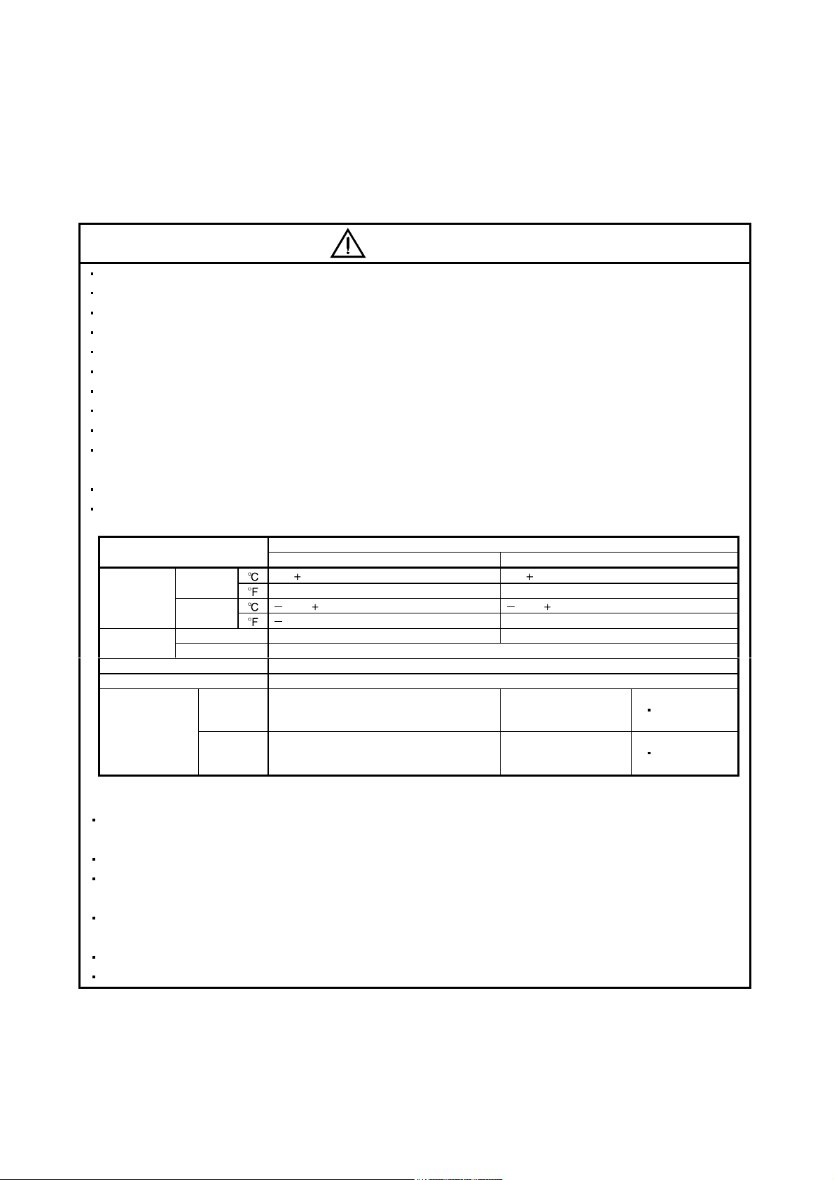
When you keep or use it, please fulfill the following environmental conditions.
Environment
During
Ambient
temperature
Ambient
humidity
Ambience Indoors (no direct sunlight) Free from corrosive gas, flammable gas, oil mist, dust and dirt
Altitude Max. 1000m (3280 ft) above sea level
(Note) Vibration
Note. Except the servo motor with reduction gear.
operation
In storage
During operation 90%RH or less (non-condensing) 80%RH or less (non-condensing)
In storage 90%RH or less (non-condensing)
[ ] 0 to 55 (non-freezing) 0 to 40 (non-freezing)
[
] 32 to 131 (non-freezing) 32 to 104 (non-freezing)
[ ] 20 to 65 (non-freezing) 15 to 70 (non-freezing)
[
] 4 to 149 (non-freezing) 5 to 158 (non-freezing)
[m/s2] 5.9 or less
2
[ft/s
] 19.4 or less
Each unit Servo motor
Conditions
HC-KFS Series
HC-MFS Series
HC-UFS13 to 43
HC-KFS Series
HC-MFS Series
HC-UFS13 to 43
X Y : 49
X Y : 161
Securely attach the servo motor to the machine. If attach insecurely, the servo motor may come off during
operation.
The servo motor with reduction gear must be installed in the specified direction to prevent oil leakage.
Take safety measures, e.g. provide covers, to prevent accidental access to the rotating parts of the servo
motor during operation.
Never hit the servo motor or shaft, especially when coupling the servo motor to the machine. The encoder
may become faulty.
Do not subject the servo motor shaft to more than the permissible load. Otherwise, the shaft may break.
When the equipment has been stored for an extended period of time, consult Mitsubishi.
A - 3
Page 5
(2) Wiring
CAUTION
Wire the equipment correctly and securely. Otherwise, the servo motor may misoperate.
Do not install a power capacitor, surge absorber or radio noise filter (FR-BIF option) between the servo
motor and drive unit.
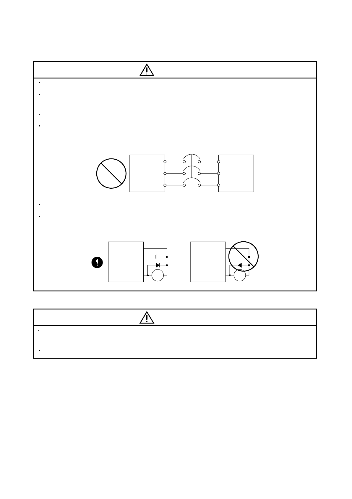
Connect the output terminals (U, V, W) correctly. Otherwise, the servo motor will operate improperly.
Connect the servo motor power terminal (U, V, W) to the servo motor power input terminal (U, V, W)
directly. Do not let a magnetic contactor, etc. intervene.
drive unit
U
V
W
Servo Motor
U
V
W
Do not connect AC power directly to the servo motor. Otherwise, a fault may occur.
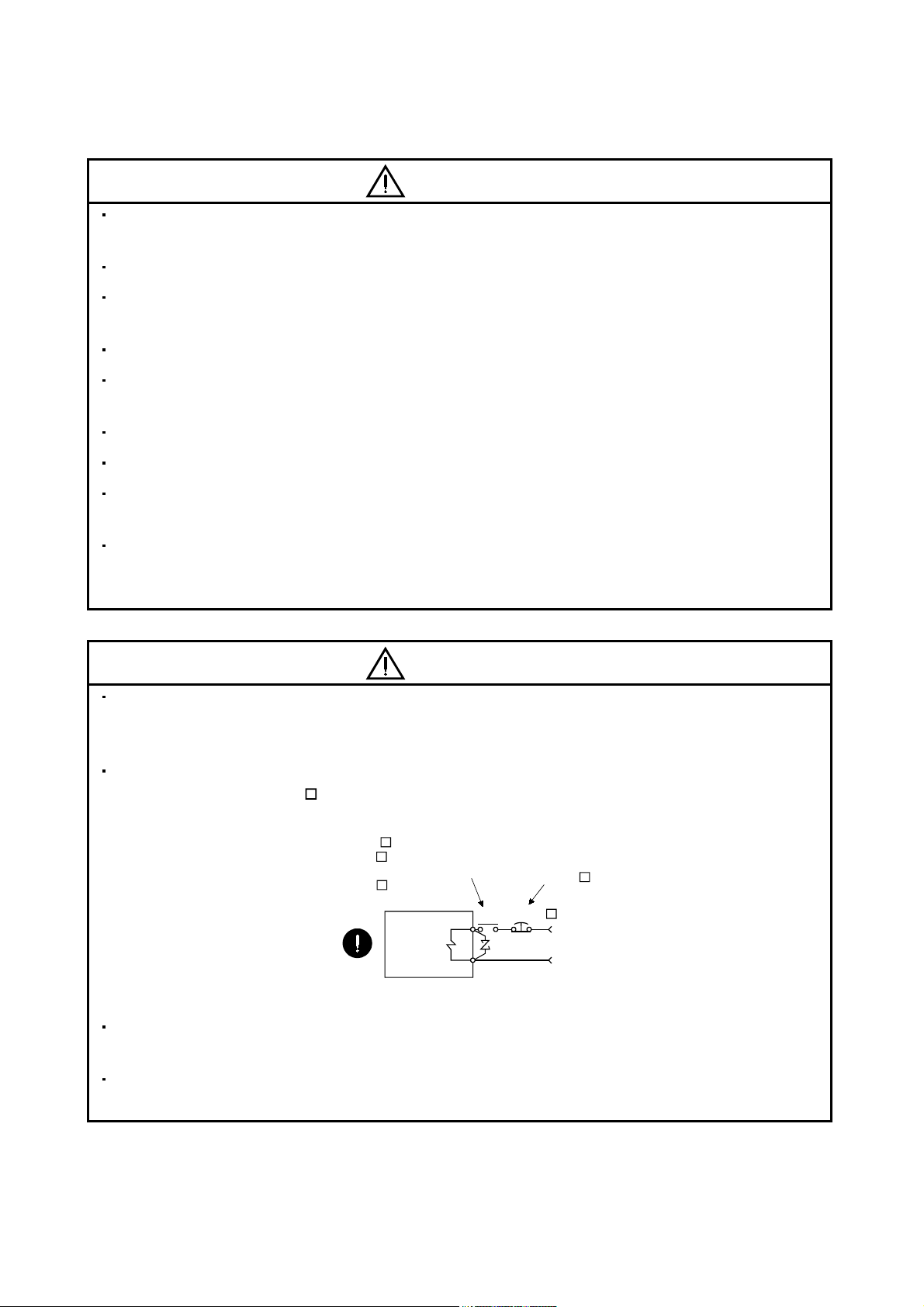
The surge absorbing diode installed on the DC output signal relay of the servo amplifier must be wired in
the specified direction. Otherwise, the forced stop and other protective circuits may not operate.
Interface unit
VIN
SG
Control output
signal
Interface unit
VIN
SG
Control output
signal
RARA
(3) Test run adjustment
CAUTION
Before operation, check the parameter settings. Improper settings may cause some machines to perform
unexpected operation.
The parameter settings must not be changed excessively. Operation will be insatiable.
A - 4
Page 6
(4) Usage
w
CAUTION
Provide an forced stop circuit to ensure that operation can be stopped and power switched off
immediately.
Any person who is involved in disassembly and repair should be fully competent to do the work.
Before resetting an alarm, make sure that the run signal of the servo amplifier is off to prevent an
accident. A sudden restart is made if an alarm is reset with the run signal on.
Do not modify the equipment.
Use a noise filter, etc. to minimize the influence of electromagnetic interference, which may be caused by
electronic equipment used near MELSERVO-J2M.
Burning or breaking each unit may cause a toxic gas. Do not burn or break each unit.
Use the drive unit with the specified servo motor.
The electromagnetic brake on the servo motor is designed to hold the motor shaft and should not be used
for ordinary braking.
For such reasons as service life and mechanical structure (e.g. where a ballscrew and the servo motor
are coupled via a timing belt), the electromagnetic brake may not hold the motor shaft. To ensure safety,
install a stopper on the machine side.
(5) Corrective actions
CAUTION
When it is assumed that a hazardous condition may take place at the occur due to a power failure or a
product fault, use a servo motor with electromagnetic brake or an external brake mechanism for the
purpose of prevention.
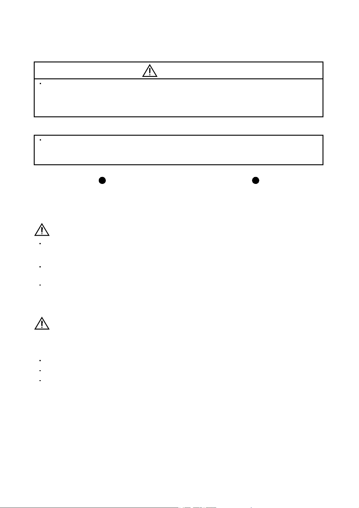
Configure the electromagnetic brake circuit so that it is activated not only by the interface unit signals but
also by a forced stop (EMG_
When any alarm has occurred, eliminate its cause, ensure safety, and deactivate the alarm before
restarting operation.
.
)
Contacts must be open when
servo-on (SON ) is off, when an
trouble (ALM_ ) is present and
hen an electromagnetic brake
interlock (MBR ).
Servo motor
Electromagnetic brake
RA
Circuit must be
opened during
forced stop
(EMG_ ).
EMG_
24VDC
When power is restored after an instantaneous power failure, keep away from the machine because the
machine may be restarted suddenly (design the machine so that it is secured against hazard if restarted).
A - 5
Page 7
(6) Maintenance, inspection and parts replacement
CAUTION
With age, the electrolytic capacitor of the drive unit will deteriorate. To prevent a secondary accident due
to a fault, it is recommended to replace the electrolytic capacitor every 10 years when used in general
environment.
Please consult our sales representative.
(7) General instruction
To illustrate details, the equipment in the diagrams of this Instruction Manual may have been drawn
without covers and safety guards. When the equipment is operated, the covers and safety guards must
be installed as specified. Operation must be performed in accordance with this Instruction Manual.
About processing of waste
When you discard servo amplifier, a battery (primary battery), and other option articles, please follow the law of
each country (area).
FOR MAXIMUM SAFETY
These products have been manufactured as a general-purpose part for general industries, and have not
been designed or manufactured to be incorporated in a device or system used in purposes related to
human life.
Before using the products for special purposes such as nuclear power, electric power, aerospace,
medicine, passenger movement vehicles or under water relays, contact Mitsubishi.
These products have been manufactured under strict quality control. However, when installing the product
where major accidents or losses could occur if the product fails, install appropriate backup or failsafe
functions in the system.
EEP-ROM life
The number of write times to the EEP-ROM, which stores parameter settings, etc., is limited to 100,000. If
the total number of the following operations exceeds 100,000, the servo amplifier and/or converter unit may
fail when the EEP-ROM reaches the end of its useful life.
Write to the EEP-ROM due to parameter setting changes
Home position setting in the absolute position detection system
Write to the EEP-ROM due to device changes
Precautions for Choosing the Products
Mitsubishi will not be held liable for damage caused by factors found not to be the cause of Mitsubishi;
machine damage or lost profits caused by faults in the Mitsubishi products; damage, secondary damage,
accident compensation caused by special factors unpredictable by Mitsubishi; damages to products other
than Mitsubishi products; and to other duties.
A - 6
Page 8
COMPLIANCE WITH EC DIRECTIVES
1. WHAT ARE EC DIRECTIVES?
The EC directives were issued to standardize the regulations of the EU countries and ensure smooth
distribution of safety-guaranteed products. In the EU countries, the machinery directive (effective in
January, 1995), EMC directive (effective in January, 1996) and low voltage directive (effective in January,
1997) of the EC directives require that products to be sold should meet their fundamental safety
requirements and carry the CE marks (CE marking). CE marking applies to machines and equipment
into which servo (MELSERVO-J2M is contained) have been installed.
(1) EMC directive
The EMC directive applies not to the servo units alone but to servo-incorporated machines and
equipment. This requires the EMC filters to be used with the servo-incorporated machines and
equipment to comply with the EMC directive. For specific EMC directive conforming methods, refer to
the EMC Installation Guidelines (IB(NA)67310).
(2) Low voltage directive
The low voltage directive applies also to MELSERVO-J2M. Hence, they are designed to comply with
the low voltage directive.
MELSERVO-J2M is certified by TUV, third-party assessment organization, to comply with the low
voltage directive.
The MELSERVO-J2M complies with EN50178.
(3) Machine directive
Not being machines, MELSERVO-J2M need not comply with this directive.
2. PRECAUTIONS FOR COMPLIANCE
(1) Unit and servo motors used
Use each units and servo motors which comply with the standard model.
Interface unit :MR-J2M-P8A
Drive unit :MR-J2MBase unit :MR-J2M-BU
Servo motor :HC-KFS
HC-MFS
HC-UFS
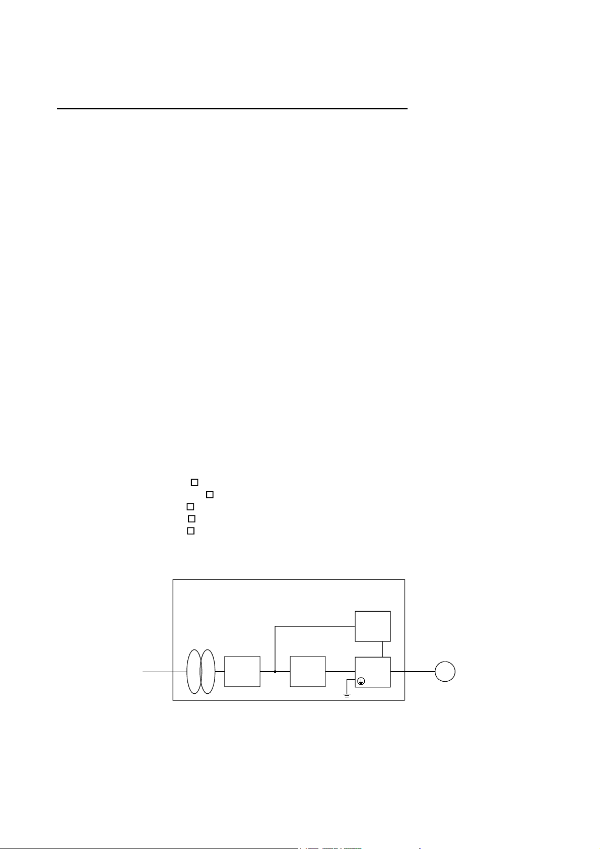
(2) Configuration
DU
Reinforced
insulating
transformer
No-fuse
breaker
NFB
Control box
Magnetic
contactor
Reinforced
insulating type
24VDC
power
supply
MELSERVOJ2M
MC
Servo
motor
M
A - 7
Page 9

(3) Environment
Operate MELSERVO-J2M at or above the contamination level 2 set forth in IEC60664-1 For this
purpose, install MELSERVO-J2M in a control box which is protected against water, oil, carbon, dust,
dirt, etc. (IP54).
(4) Power supply
(a) Operate MELSERVO-J2M to meet the requirements of the overvoltage category II set forth in
IEC60664-1 For this purpose, a reinforced insulating transformer conforming to the IEC or EN
standard should be used in the power input section.
(b) When supplying interface power from external, use a 24VDC power supply which has been
insulation-reinforced in I/O.
(5) Grounding
(a) To prevent an electric shock, always connect the protective earth (PE) terminals (marked
base unit to the protective earth (PE) of the control box.
(b) Do not connect two ground cables to the same protective earth (PE) terminal. Always connect the
cables to the terminals one-to-one.
(c) If a leakage current breaker is used to prevent an electric shock, the protective earth (PE) terminals
of the base unit must be connected to the corresponding earth terminals.
) of the
(d) The protective earth (PE) of the servo motor is connected to the protective earth of the base unit via
the screw which fastens the drive unit to the base unit. When fixing the drive unit to the base unit,
therefore, tighten the accessory screw securely.
(6) Auxiliary equipment and options
(a) The no-fuse breaker and magnetic contactor used should be the EN or IEC standard-compliant
products of the models described in Section 12.2.2.
(b) The sizes of the cables described in Section 12.2.1 meet the following requirements. To meet the
other requirements, follow Table 5 and Appendix C in EN60204-1.
Ambient temperature: 40 (104) [ ( )]
Sheath: PVC (polyvinyl chloride)
Installed on wall surface or open table tray
(c) Use the EMC filter for noise reduction.
(7) Performing EMC tests
When EMC tests are run on a machine/device into which MELSERVO-J2M has been installed, it must
conform to the electromagnetic compatibility (immunity/emission) standards after it has satisfied the
operating environment/electrical equipment specifications.
For the other EMC directive guidelines on MELSERVO-J2M, refer to the EMC Installation
Guidelines(IB(NA)67310).
A - 8
Page 10
CONFORMANCE WITH UL/C-UL STANDARD
The MELSERVO-J2M complies with UL508C.
(1) Unit and servo motors used
Use the each units and servo motors which comply with the standard model.
Interface unit :MR-J2M-P8A
Drive unit :MR-J2MBase unit :MR-J2M-BU
Servo motor :HC-KFS
HC-MFS
HC-UFS
(2) Installation
Install a fan of 100CFM (2.8m
cooling of at least equivalent capability.
(3) Short circuit rating
MELSERVO-J2M conforms to the circuit whose peak current is limited to 5000A or less. Having been
subjected to the short-circuit tests of the UL in the alternating-current circuit, MELSERVO-J2M
conforms to the above circuit.
DU
3
/min) air flow 4 [in] (10.16 [cm]) above the servo amplifier or provide
(4) Capacitor discharge time
The capacitor discharge time is as listed below. To ensure safety, do not touch the charging section for
15 minutes after power-off.
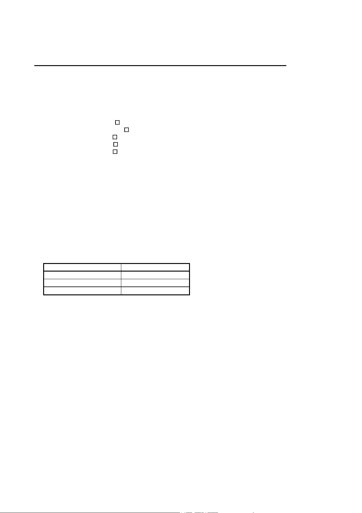
Base unit Discharge time [min]
MR-J2M-BU4 1
MR-J2M-BU6 1
MR-J2M-BU8 1
(5) Options and auxiliary equipment
Use UL/C-UL standard-compliant products.
(6) Attachment of a servo motor
For the flange size of the machine side where the servo motor is installed, refer to “CONFORMANCE
WITH UL/C-UL STANDARD” in the Servo Motor Instruction Manual.
(7) About wiring protection
For installation in United States, branch circuit protection must be provided, in accordance with the
National Electrical Code and any applicable local codes.
For installation in Canada, branch circuit protection must be provided, in accordance with the Canada
Electrical Code and any applicable provincial codes.
A - 9
Page 11

<<About the manuals>>
This Instruction Manual and the MELSERVO Servo Motor Instruction Manual are required if you use
MELSERVO-J2M for the first time. Always purchase them and use the MELSERVO-J2M safely.
Also read the manual of the servo system controller.
Relevant manuals
Manual name Manual No.
MELSERVO-J2M Series To Use the AC Servo Safely
(Packed with the MR-J2M-P8A, MR-J2MMELSERVO Servo Motor Instruction Manual SH(NA)3181
EMC Installation Guidelines IB(NA)67310
DU and MR-J2M-BU )
IB(NA)0300027
In this Instruction Manual, the drive unit, interface unit and base unit may be referred to as follows:
Drive unit : DRU
Interface unit : IFU
Base unit : BU
A - 10
Page 12

CONTENTS
1. FUNCTIONS AND CONFIGURATION 1- 1 to 1-10
1.1 Overview................................................................................................................................................... 1- 1
1.2 Function block diagram ..........................................................................................................................1- 2
1.3 Unit standard specifications................................................................................................................... 1- 3
1.4 Function list ............................................................................................................................................. 1- 4
1.5 Model code definition .............................................................................................................................. 1- 5
1.6 Combination with servo motor............................................................................................................... 1- 6
1.7 Parts identification.................................................................................................................................. 1- 7
1.8 Servo system with auxiliary equipment................................................................................................ 1- 9
2. INSTALLATION AND START UP 2- 1 to 2-10
2.1 Environmental conditions....................................................................................................................... 2- 1
2.2 Installation direction and clearances .................................................................................................... 2- 2
2.3 Keep out foreign materials .....................................................................................................................2- 3
2.4 Cable stress .............................................................................................................................................. 2- 3
2.5 Mounting method ....................................................................................................................................2- 4
2.6 When switching power on for the first time.......................................................................................... 2- 6
2.7 Start up..................................................................................................................................................... 2- 7
3. SIGNALS AND WIRING 3- 1 to 3-48
3.1 Control signal line connection example................................................................................................. 3- 2
3.2 I/O signals of interface unit .................................................................................................................... 3- 5
3.2.1 Connectors and signal arrangements ............................................................................................. 3- 5
3.2.2 Signal explanations .......................................................................................................................... 3- 6
3.2.3 Detailed description of the signals................................................................................................. 3-11
3.2.4 Internal connection diagram ..........................................................................................................3-15
3.2.5 Interface............................................................................................................................................3-16
3.3 Signal and wiring for extension IO unit............................................................................................... 3-20
3.3.1 Connection example ........................................................................................................................ 3-20
3.3.2 Connectors and signal configurations ........................................................................................... 3-22
3.3.3 Signal explanations ......................................................................................................................... 3-23
3.3.4 Device explanations......................................................................................................................... 3-26
3.3.5 Detailed description of the device ..................................................................................................3-30
3.3.6 Device assignment method ............................................................................................................. 3-31
3.4 Signals and wiring for base unit ........................................................................................................... 3-35
3.4.1 Connection example for power line circuit ....................................................................................3-35
3.4.2 Connectors and signal configurations ........................................................................................... 3-37
3.4.3 Terminals.......................................................................................................................................... 3-38
3.4.4 Power-on sequence........................................................................................................................... 3-38
3.5 Connection of drive unit and servo motor ............................................................................................ 3-39
3.5.1 Connection instructions ..................................................................................................................3-39
3.5.2 Connection diagram ........................................................................................................................ 3-40
3.5.3 I/O terminals .................................................................................................................................... 3-41
3.6 Alarm occurrence timing chart .............................................................................................................3-42
1
Page 13

3.7 Servo motor with electromagnetic brake ............................................................................................. 3-43
3.8 Grounding................................................................................................................................................ 3-46
3.9 Instructions for the 3M connector......................................................................................................... 3-47
4. OPERATION AND DISPLAY 4- 1 to 4-18
4.1 Display flowchart..................................................................................................................................... 4- 1
4.1.1 Normal indication ............................................................................................................................. 4- 2
4.1.2 If alarm/warning occurs ................................................................................................................... 4- 3
4.1.3 If test operation................................................................................................................................. 4- 4
4.2 Interface unit display .............................................................................................................................. 4- 5
4.2.1 Display flowchart of interface unit ................................................................................................. 4- 5
4.2.2 Status display of interface unit .......................................................................................................4- 6
4.2.3 Diagnostic mode of interface unit ................................................................................................... 4- 7
4.2.4 Alarm mode of interface unit........................................................................................................... 4- 8
4.2.5 Interface unit parameter mode ....................................................................................................... 4- 9
4.2.6 Interface unit output signal (DO) forced output...........................................................................4-10
4.3 Drive unit display ...................................................................................................................................4-11
4.3.1 Drive unit display sequence............................................................................................................ 4-11
4.3.2 Status display of drive unit............................................................................................................. 4-12
4.3.3 Diagnostic mode of drive unit......................................................................................................... 4-14
4.3.4 Alarm mode of drive unit ................................................................................................................ 4-15
4.3.5 Drive unit parameter mode ............................................................................................................4-16
4.3.6 Drive unit external input signal display ....................................................................................... 4-16
4.3.7 Drive unit external output signal display ..................................................................................... 4-17
4.3.8 Drive unit output signal (DO) forced output................................................................................. 4-18
5. PARAMETERS 5- 1 to 5-30
5.1 DRU parameter list................................................................................................................................. 5- 1
5.1.1 DRU parameter write inhibit .......................................................................................................... 5- 1
5.1.2 Lists.................................................................................................................................................... 5- 2
5.2 Interface unit ..........................................................................................................................................5-14
5.2.1 IFU parameter write inhibit........................................................................................................... 5-14
5.2.2 Lists...................................................................................................................................................5-14
5.3 Detailed description ...............................................................................................................................5-21
5.3.1 Electronic gear ................................................................................................................................. 5-21
5.3.2 Analog monitor................................................................................................................................. 5-25
5.3.3 Using forward rotation stroke end (LSP
) reverse rotation stroke end (LSN ) to change the
stopping pattern.............................................................................................................................. 5-28
5.3.4 Alarm history clear.......................................................................................................................... 5-28
5.3.5 Position smoothing ..........................................................................................................................5-29
6. GENERAL GAIN ADJUSTMENT 6- 1 to 6-10
6.1 Different adjustment methods ...............................................................................................................6- 1
6.1.1 Adjustment on a MELSERVO-J2M................................................................................................ 6- 1
6.1.2 Adjustment using MR Configurator (servo configuration software) ...........................................6- 2
6.2 Auto tuning ..............................................................................................................................................6- 3
6.2.1 Auto tuning mode .............................................................................................................................6- 3
2
Page 14

6.2.2 Auto tuning mode operation ............................................................................................................ 6- 4
6.2.3 Adjustment procedure by auto tuning............................................................................................ 6- 5
6.2.4 Response level setting in auto tuning mode .................................................................................. 6- 6
6.3 Manual mode 1 (simple manual adjustment)....................................................................................... 6- 7
6.3.1 Operation of manual mode 1 ........................................................................................................... 6- 7
6.3.2 Adjustment by manual mode 1 ....................................................................................................... 6- 7
6.4 Interpolation mode .................................................................................................................................. 6- 9
7. SPECIAL ADJUSTMENT FUNCTIONS 7- 1 to 7-10
7.1 Function block diagram ..........................................................................................................................7- 1
7.2 Machine resonance suppression filter ................................................................................................... 7- 1
7.3 Adaptive vibration suppression control................................................................................................. 7- 3
7.4 Low-pass filter ......................................................................................................................................... 7- 4
7.5 Gain changing function........................................................................................................................... 7- 5
7.5.1 Applications....................................................................................................................................... 7- 5
7.5.2 Function block diagram ................................................................................................................... 7- 5
7.5.3 Parameters ........................................................................................................................................ 7- 6
7.5.4 Gain changing operation.................................................................................................................. 7- 8
8. INSPECTION 8- 1 to 8- 2
9. TROUBLESHOOTING 9- 1 to 9-14
9.1 Trouble at start-up .................................................................................................................................. 9- 1
9.2 Alarms and warning list ......................................................................................................................... 9- 4
9.3 Remedies for alarms................................................................................................................................ 9- 6
9.4 Remedies for warnings...........................................................................................................................9-13
10. OUTLINE DRAWINGS 10- 1 to 10-10
10.1 MELSERVO-J2M configuration example.........................................................................................10- 1
10.2 Unit outline drawings ......................................................................................................................... 10- 2
10.2.1 Base unit (MR-J2M-BU
) ...........................................................................................................10- 2
10.2.2 Interface unit (MR-J2M-P8A) .....................................................................................................10- 2
10.2.3 Drive unit (MR-J2M-
DU)......................................................................................................... 10- 3
10.2.4 Extension IO unit (MR-J2M-D01) ..............................................................................................10- 4
10.2.5 Battery unit (MR-J2M-BT).......................................................................................................... 10- 4
10.3 Connectors............................................................................................................................................ 10- 5
11. CHARACTERISTICS 11- 1 to 11- 6
11.1 Overload protection characteristics ................................................................................................... 11- 1
11.2 Power supply equipment capacity and generated loss ....................................................................11- 2
11.3 Dynamic brake characteristics...........................................................................................................11- 4
11.4 Encoder cable flexing life ....................................................................................................................11- 6
12. OPTIONS AND AUXILIARY EQUIPMENT 12- 1 to 12-36
12.1 Options.................................................................................................................................................. 12- 1
3
Page 15

12.1.1 Regenerative brake options ......................................................................................................... 12- 1
12.1.2 Cables and connectors ..................................................................................................................12- 8
12.1.3 Junction terminal block (MR-TB50) .......................................................................................... 12-17
12.1.4 Junction terminal block (MR-TB20) .......................................................................................... 12-19
12.1.5 Maintenance junction card (MR-J2CN3TM) ............................................................................12-21
12.1.6 MR Configurator (servo configurations software) .................................................................... 12-23
12.2 Auxiliary equipment ..........................................................................................................................12-24
12.2.1 Recommended wires ....................................................................................................................12-24
12.2.2 No-fuse breakers, fuses, magnetic contactors........................................................................... 12-26
12.2.3 Power factor improving reactors ................................................................................................12-27
12.2.4 Relays............................................................................................................................................ 12-28
12.2.5 Surge absorbers ...........................................................................................................................12-28
12.2.6 Noise reduction techniques.........................................................................................................12-28
12.2.7 Leakage current breaker ............................................................................................................ 12-34
12.2.8 EMC filter..................................................................................................................................... 12-35
13. COMMUNICATION FUNCTIONS 13- 1 to 13-32
13.1 Configuration ....................................................................................................................................... 13- 1
13.1.1 RS-422 configuration.................................................................................................................... 13- 1
13.1.2 RS-232C configuration ................................................................................................................. 13- 3
13.2 Communication specifications............................................................................................................ 13- 4
13.2.1 Communication overview ............................................................................................................ 13- 4
13.2.2 Parameter setting .........................................................................................................................13- 5
13.3 Protocol ................................................................................................................................................. 13- 6
13.4 Character codes ...................................................................................................................................13- 7
13.5 Error codes ...........................................................................................................................................13- 8
13.6 Checksum .............................................................................................................................................13- 8
13.7 Time-out operation .............................................................................................................................. 13- 9
13.8 Retry operation .................................................................................................................................... 13- 9
13.9 Initialization........................................................................................................................................13-10
13.10 Communication procedure example ...............................................................................................13-10
13.11 Command and data No. list............................................................................................................. 13-11
13.11.1 Read commands .........................................................................................................................13-11
13.11.2 Write commands ........................................................................................................................13-13
13.12 Detailed explanations of commands ............................................................................................... 13-15
13.12.1 Data processing.......................................................................................................................... 13-15
13.12.2 Status display ............................................................................................................................13-17
13.12.3 Parameter...................................................................................................................................13-18
13.12.4 External I/O pin statuses (DIO diagnosis) ..............................................................................13-20
13.12.5 Disable/enable of external I/O signals (DIO) ..........................................................................13-23
13.12.6 External input signal ON/OFF (test operation) .....................................................................13-24
13.12.7 Test operation mode ..................................................................................................................13-25
13.12.8 Output signal pin ON/OFF (output signal (DO) forced output) ...........................................13-28
13.12.9 Alarm history ............................................................................................................................. 13-29
13.12.10 Current alarm .......................................................................................................................... 13-30
13.12.11 Other commands...................................................................................................................... 13-31
4
Page 16

14. ABSOLUTE POSITION DETECTION SYSTEM 14- 1 to 14-12
14.1 Outline.................................................................................................................................................. 14- 1
14.1.1 Features......................................................................................................................................... 14- 1
14.1.2 Restrictions.................................................................................................................................... 14- 1
14.2 Specifications .......................................................................................................................................14- 2
14.3 Signal explanation............................................................................................................................... 14- 3
14.4 Serial communication command........................................................................................................ 14- 3
14.5 Startup procedure................................................................................................................................ 14- 4
14.6 Absolute position data transfer protocol ........................................................................................... 14- 5
14.6.1 Data transfer procedure............................................................................................................... 14- 5
14.6.2 Transfer method ...........................................................................................................................14- 6
14.6.3 Home position setting .................................................................................................................. 14- 9
14.6.4 How to process the absolute position data at detection of stroke end.................................... 14-10
14.7 Confirmation of absolute position detection data............................................................................ 14-11
APPENDIX App- 1 to App- 2
App 1. Status indication block diagram ................................................................................................. App- 1
5
Page 17

Optional Servo Motor Instruction Manual CONTENTS
The rough table of contents of the optional MELSERVO Servo Motor Instruction Manual is introduced
here for your reference. Note that the contents of the Servo Motor Instruction Manual are not included in
this Instruction Manual.
1. INTRODUCTION
2. INSTALLATION
3. CONNECTORS USED FOR SERVO MOTOR WIRING
4. INSPECTION
5. SPECIFICATIONS
6. CHARACTERISTICS
7. OUTLINE DIMENSION DRAWINGS
8. CALCULATION METHODS FOR DESIGNING
6
Page 18
1. FUNCTIONS AND CONFIGURATION
1. FUNCTIONS AND CONFIGURATION
1.1 Overview
The Mitsubishi general-purpose AC servo MELSERVO-J2M series is an AC servo which has realized
wiring-saving, energy-saving and space-saving in addition to the high performance and high functions of
the MELSERVO-J2-Super series.
The MELSERVO-J2M series consists of an interface unit (abbreviated to the IFU) to be connected with a
positioning unit, drive units (abbreviated to the DRU) for driving and controlling servo motors, and a base
unit (abbreviated to the BU) where these units are installed.
A torque limit is applied to the drive unit by the clamp circuit to protect the main circuit power
transistors from overcurrent caused by abrupt acceleration/deceleration or overload. In addition, the
torque limit value can be changed as desired using the parameter.
The interface unit has an RS-232C or RS-422 serial communication function to allow the parameter
setting, test operation, status indication monitoring, gain adjustment and others of all units to be
performed using a personal computer or like where the MR Configurator (servo configuration software) is
installed. By choosing the station number of the drive unit using the MR Configurator (servo
configuration software), you can select the unit to communicate with, without changing the cabling.
The real-time auto tuning function automatically adjusts the servo gains according to a machine.
A maximum 500kpps high-speed pulse train is used to control the speed and direction of a motor and
execute accurate positioning of 131072 pulses/rev resolution.
The position smoothing function has two different systems to allow you to select the appropriate system
for a machine, achieving a smoother start/stop in response to an abrupt position command.
The MELSERVO-J2M series supports as standard the absolute position encoders which have 131072
pulses/rev resolution, ensuring control as accurate as that of the MELSERVO-J2-Super series. Simply
adding the optional battery unit configures an absolute position detection system. Hence, merely setting a
home position once makes it unnecessary to perform a home position return at power-on, alarm
occurrence or like.
The MELSERVO-J2M series has a control circuit power supply in the interface unit and main circuit
converter and regenerative functions in the base unit to batch-wire the main circuit power input,
regenerative brake connection and control circuit power supply input, achieving wiring-saving.
In the MELSERVO-J2M series, main circuit converter sharing has improved the capacitor regeneration
capability dramatically. Except for the operation pattern where all axes slow down simultaneously, the
capacitor can be used for regeneration. You can save the energy which used to be consumed by the
regenerative brake resistor.
Regenerative
brake option
Control circuit power
supply input
Main circuit power input
Forward rotation stroke end
Reverse rotation stroke end
Forced stop input
Input signal (Axes 1 to 4)
Input signal (Axes 5 to 8)
Extension IO unit
MR-J2M-D01
Encoder pulse output
extension DIO (Axes 1 to 4)
Encoder pulse output
extension DIO (Axes 5 to 8)
Encoder cable
Servo motor power cable
Personal computer connection
Monitor output
Forced stop input
Electromagnetic brake interlock output
1 - 1
Page 19
1. FUNCTIONS AND CONFIGURATION
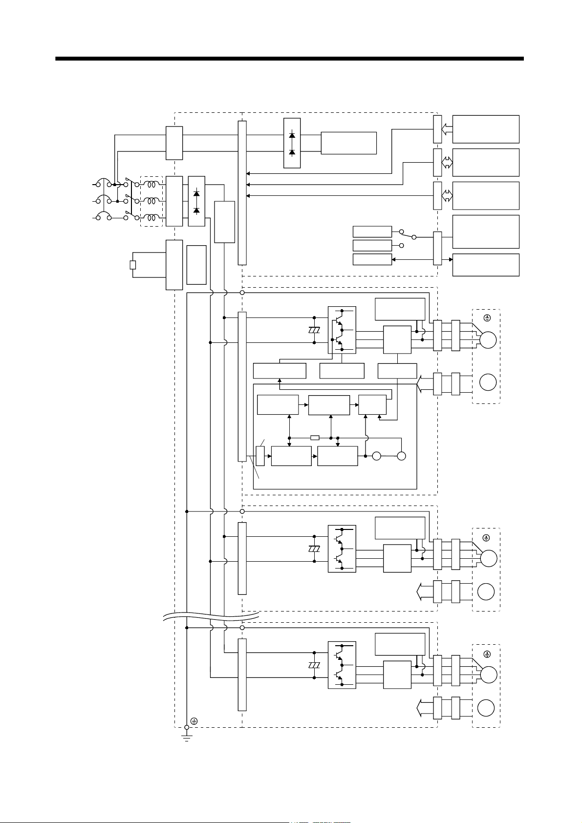
1.2 Function block diagram
Base unit Interface unit
CNP1B
11
CNP1A
L
L
21
L1
L
L
P
N
C
CNP3
2
3
Inrush current
suppression
circuit
Regener-
ative TR
Power
supply
3-phase
200 to
NFB MC
230VAC
(Note)
1-phase
200 to
230VAC
Regenerative brake option
FR-BAL
Control circuit
power suppy
Pulse train position command
Pulse train position command
RS-232C
RS-422
D/A
Drive unit
Input signal
Stroke end
CN5
Forced stop
I/O signals
for slots 1 to 4,
CN1ACN1BCN3CNP2CN2CNP2CN2
e.g. servo-on
I/O signals
for slots 5 to 8,
e.g. servo-on
Personal computer
or
other servo amplifier
Analog monitor
(3 channels)
Overcurrent
Base amplifie
Actual position
control
Pulse
counter
Pulse train position command
r
Model
position
Model position
control
protection
Actual speed
control
Model speed
control
Drive unit
Model
speed
Current
control
Virtual
servo
motor
Dynamic
brake
Current
detector
Current
detection
Model
torque
Virtual
encoder
Dynamic
brake
Current
detection
Servo motor
(Earth)
U
V
M
W
Encoder
Servo motor
(Earth)
U
V
M
W
Drive unit
Dynamic
brake
Current
detection
CON3A-3H CON3A-3H CON3A-3H
Note. For 1-phase 200 to 230VAC, connect the power supply to L1, L2 and leave L3 open.
1 - 2
CNP2CN2
Encoder
Servo motor
(Earth)
U
V
M
W
Encoder
Page 20
1. FUNCTIONS AND CONFIGURATION
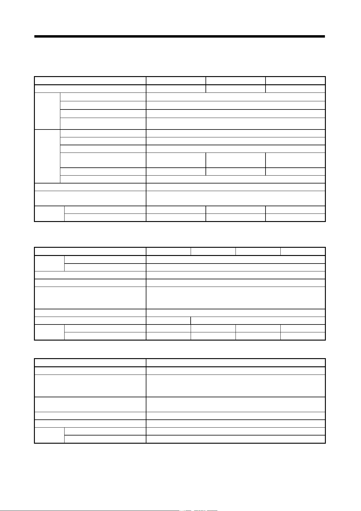
1.3 Unit standard specifications
(1) Base unit
Model MR-J2M-BU4 MR-J2M-BU6 MR-J2M-BU8
Number of slots 4 slots 6 slots 8 slots
(Note)
Control
circuit
power
supply
Main
circuit
power
supply
Function Converter function, regenerative control, rushing into current control function
Protective functions
Mass
Note. The control circuit power supply is recorded to the interface unit.
Voltage/frequency 3-phase 200 to 230VAC or 1-phase 200 to 230VAC, 50/60Hz
Permissible voltage fluctuation 1-phase 170 to 253VAC
Permissible frequency fluctuation Within 5%
Inrush current 20A (5ms)
Voltage/frequency 3-phase 200 to 230VAC or 1-phase 200 to 230VAC, 50/60Hz
Permissible voltage fluctuation 3-phase 170 to 253VAC or 1-phase 170 to 253VAC, 50/60 Hz
Permissible frequency fluctuation Within 5%
Maximum servo motor connection
capacity [W]
Continuous capacity [W] 1280 1920 2560
Inrush current 62.5A (15ms)
Regenerative overvoltage shut-off, regenerative fault protection,
undervoltage /instantaneous power failure protection
[kg] 1.1 1.3 1.5
[lb] 2.4 2.9 3.3
1600 2400 3200
(2) Drive unit
Model MR-J2M-10DU MR-J2M-20DU MR-J2M-40DU MR-J2M-70DU
Power
supply
Control system Sine-wave PWM control, current control system
Dynamic brake Built-in
Protective functions
Structure Open (IP00)
Cooling method Self-cooled Force-cooling (With built-in fan unit)
Mass
Voltage/frequency 270 to 311VDC
Permissible voltage fluctuation 230 to 342VDC
Overcurrent shut-off, functions overload shut-off (electronic thermal relay), servo
motor overheat protection, encoder fault protection, overspeed protection,
excessive error protection
[kg] 0.4 0.4 0.4 0.7
[lb] 0.89 0.89 0.89 1.54
(3) Interface unit
Model MR-J2M-P8A
Control circuit power supply Power supply circuit for each unit(8 slots or less)
Pulse train interface 8 channels
Interface
DIO
AIO Analog monitor 3channels
Structure Open (IP00)
Mass
[kg] 0.5
Forced stop input (2 points), alarm output (2 points), input signal (40 points),
output signal (16 points)
[lb] 1.10
RS-232C interface 1 channel
RS-422 interface 1 channel
1 - 3
Page 21
1. FUNCTIONS AND CONFIGURATION
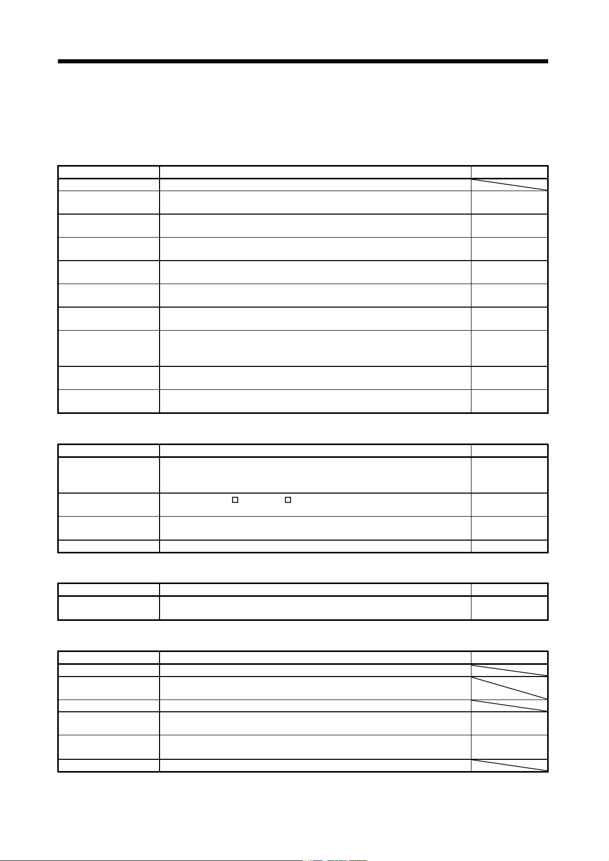
1.4 Function list
The following table lists the functions of this servo. For details of the functions, refer to the Reference
field.
(1) Drive unit (Abbreviation DRU)
Function Description Reference
High-resolution encoder High-resolution encoder of 131072 pulses/rev is used as a servo motor encoder.
Auto tuning
Gain changing function
Adaptive vibration
suppression control
Low-pass filter
Position smoothing Speed can be increased smoothly in response to input pulse.
Slight vibration
suppression control
Electronic gear Input pulses can be multiplied by 1/50 to 50.
Torque limit Servo motor torque can be limited to any value.
Command pulse selection Command pulse train form can be selected from among four different types.
Automatically adjusts the gain to optimum value if load applied to the servo motor
shaft varies.
You can switch between gains during rotation and gains during stop or use an
external signal to change gains during operation.
MELSERVO-J2M detects mechanical resonance and sets filter characteristics
automatically to suppress mechanical vibration.
Suppresses high-frequency resonance which occurs as servo system response is
increased.
Suppresses vibration of 1 pulse produced at a servo motor stop.
Chapter 7
Section 7.5.4
Section 7.3
Section 7.4
DRU parameter
No. 7
DRU parameter
No.20
DRU parameters
No. 3, 4, 69 to 71
Section 5.3.1
DRU parameters
No.28
DRU parameter
No. 21
(2) Interface unit (Abbreviation IFU)
Function Description Reference
Section 2.7
Position control mode This servo is used as position control servo.
I/O signal selection
Status display Servo status is shown on the 5-digit, 7-segment LED display
Analog monitor Servo status is output in terms of voltage in real time. Section 5.3.2
The servo-on (SON
any other pins.
, ready (RD) and other input signals can be reassigned to
)
Section 3.1.2
Section 3.1.5
Section 3.2.6
Section 4.2.2
Section 4.3.2
(3) Base unit (Abbreviation BU)
Function Description Reference
Regenerative brake option
Used when the built-in regenerative brake resistor of the unit does not have
sufficient regenerative capability for the regenerative power generated.
Section 12.1.1
(4) MR Configurator (servo configuration software)
Function Description Reference
Machine analyzer function Analyzes the frequency characteristic of the mechanical system.
Machine simulation
Gain search function Can simulate machine motions on the basis of the machine analyzer results.
External I/O signal
display
Output signal (DO)
forced output
Test operation mode JOG operation and positioning operation are possible.
Can simulate machine motions on a personal computer screen on the basis of the
machine analyzer results.
ON/OFF statuses of external I/O signals are shown on the display.
Output signal can be forced on/off independently of the servo status.
Use this function for output signal wiring check, etc.
Section 4.3.7
Section 4.2.6
Section 4.3.8
1 - 4
Page 22
1. FUNCTIONS AND CONFIGURATION
(5) Option unit
Function Description Reference
Absolute position
detection system
Encoder pulse output
1.5 Model code definition
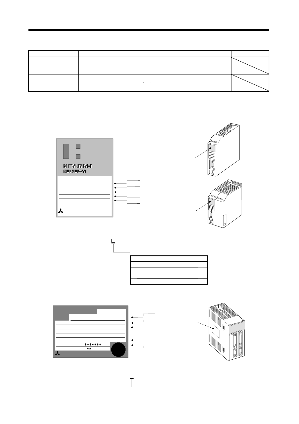
(1) Drive unit
(a) Rating plate
Merely setting a home position once makes home position return unnecessary at
every power-on.
Battery unit MR-J2M-BT (shortly correspondence schedule) is necessary.
The encoder feedback is output from extension IO unit MR-J2M-D01 (shortly
correspondence schedule) by the A
output by the parameter can be changed.
SON
B Z phase pulse. The number of pulses
MODEL
POWER
INPUT
OUTPUT
SERIAL
TC300A***G51
(b) Model code
(2) Interface unit
(a) Rating plate
ALM
MR-J2M-40DU
400W
DC270V-311V
170V 0-360Hz 2.3A
N9Z95046
MITSUBISHI ELECTRIC
MR-J2M- DU
Rating plate
Model
Capacity
Applicable power supply
Rated output current
Serial number
Rating plate
Rated output
Symbol Capacity of applied servo motor
10
20
40
70 750
100
200
400
MITSUBISHI
MODEL
POWER :
AC INPUT:
POWER
OUTPUT :
SERIAL :
MITSUBISHI ELECTRIC CORPORATION
MADE IN JAPAN
(b) Model code
AC SERVO
MR-J2M-P8A
75W
2PH AC200-230V 50Hz
2PH AC200-230V 60Hz
DC5/12/20 4.6A/1.2/0.7A
A5
AAAAG52
TC3
MR-J2M-P8A
AC SERVO
PASSED
Model
Input capacity
Applicable
power supply
Output voltage / current
Serial number
Pulse train interface compatible
Rating
plate
1 - 5
Page 23
1. FUNCTIONS AND CONFIGURATION
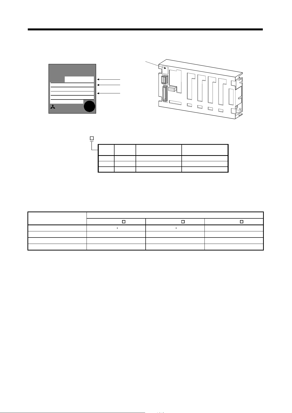
(3) Base unit
(a) Rating plate
Rating plate
MITSUBISHI
MODEL
INPUT :
SERIAL:
N87B95046
BC336U246
MITSUBISHI ELECTRIC
MADE IN JAPAN
(b) Model code
MR-J2M-BU
MR-J2M-BU4
3PH 200-230
14A 50/60Hz
PASSED
Model
Applicable power
supply
Serial number
Symbol
Number of
slots
4
61920
8
Maximum servo motor
connection capacity [W]
4
6
8
1600
2400
3200
Continuous capacity [W]
1280
2560
1.6 Combination with servo motor
The following table lists combinations of drive units and servo motors. The same combinations apply to
the models with electromagnetic brakes and the models with reduction gears.
Drive unit
MR-J2M-10DU 053 13 053 13 13
MR-J2M-20DU 23 23 23
MR-J2M-40DU 43 43 43
MR-J2M-70DU 73 73 73
HC-KFS
Servo motor
HC-MFS HC-UFS
1 - 6
Page 24
1. FUNCTIONS AND CONFIGURATION
A
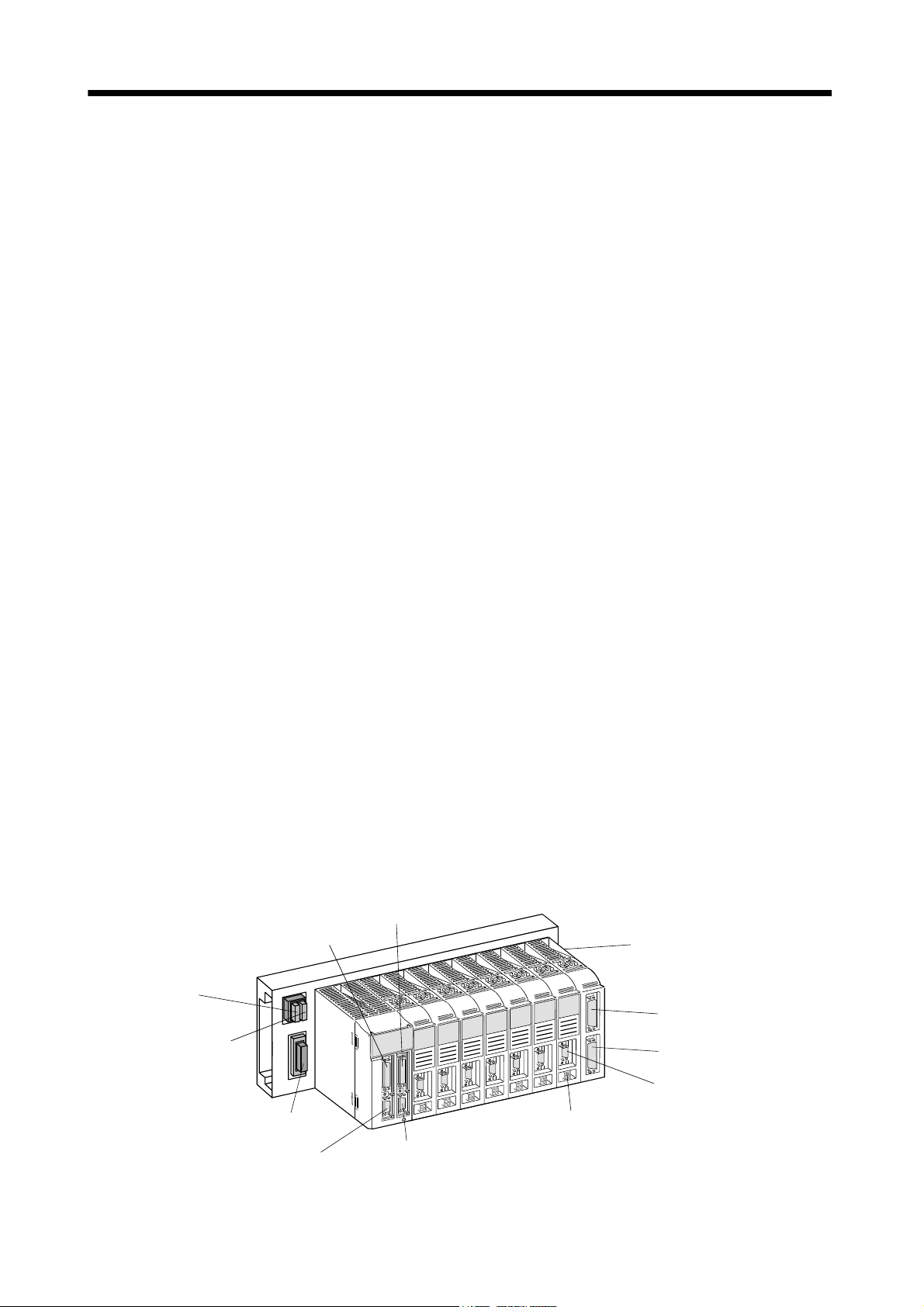
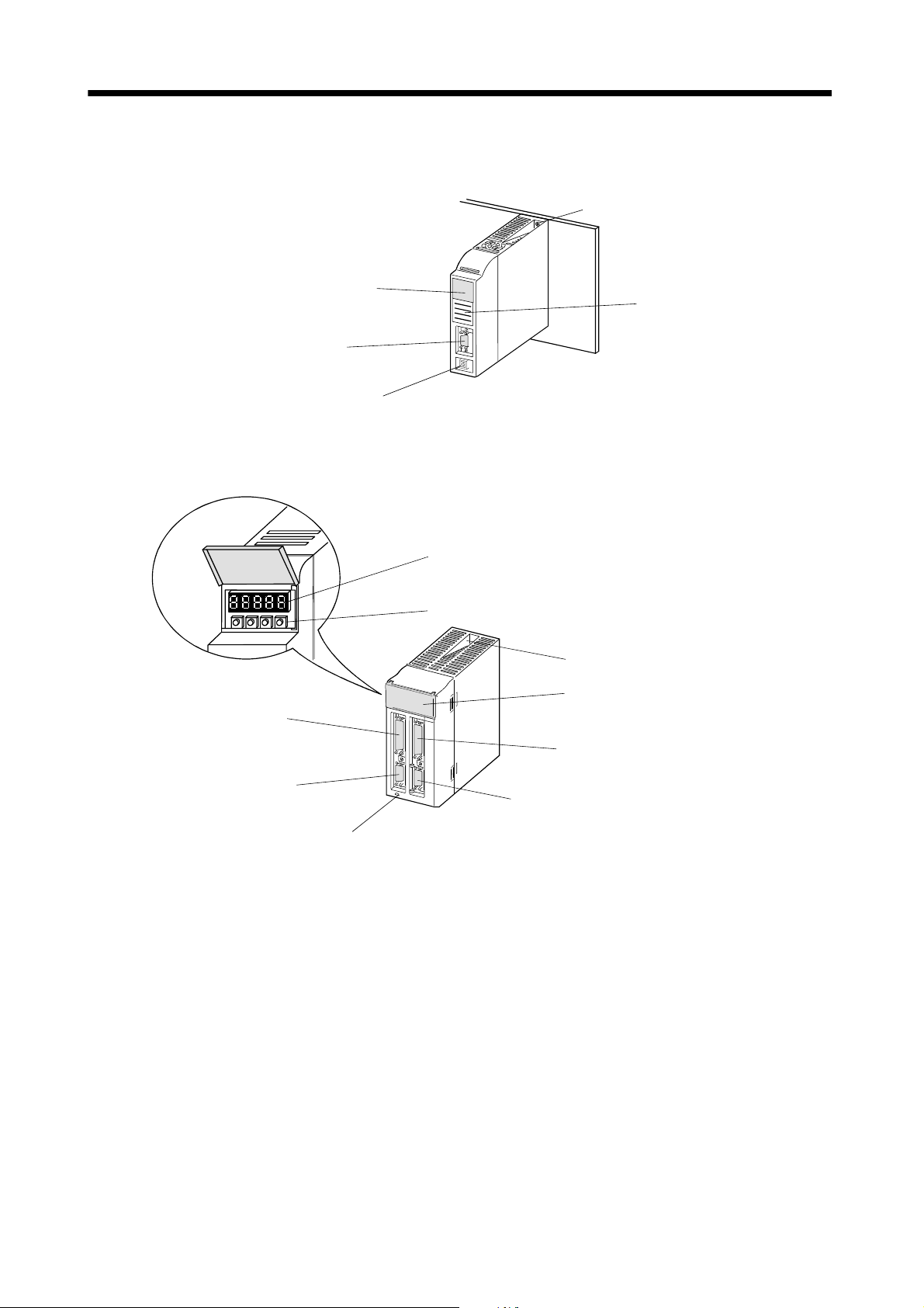
1.7 Parts identification
(1) Drive unit
Status indicator LED
Indicates the status of the drive unit.
Blinking green: Servo off status
Steady green: Servo on status
Blinking red: Warning status
Steady red: Alarm status
CN2
Encoder connector
Connect the
servo motor encoder
CNP2
Servo motor connector
For connection of servo
motor power line cable
(2) Interface unit
Mounting screw
Rating plate
CN1
I/O signal (For 1 to 4 slots)
CN5
Forward rotation stroke end
Reverse rotation stroke end
Forced stop input
Display
Indicates operating status or alarm.
Pushbutton switches
Used to change status indication or set IFU parameters
and DRU parameters.
Mounting screw
Display/setting cover
CN1B
I/O signal (For 5 to 8 slots)
CN3
For connection of personal computer (RS-232C).
Outputs analog monitor.
Charge lamp
Lit when main circuit capacitor carries electrical charge.
When this lamp is on, do not remove/reinstall any unit
from/to base unit and do not unplug/plug cable and
connector from/into any unit.
1 - 7
Page 25
1. FUNCTIONS AND CONFIGURATION
A
r
r
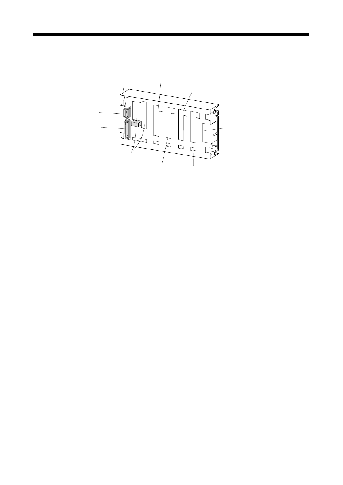
(3) Base unit
The following shows the MR-J2M-BU4.
CNP1B
Control circuit power input connector
CNP1
Regenerative brake
option connecto
CON3A
First slot connector
CON3C
Third slot connector
CNP3
Main circuit power
input connector
CON1,CON2
Interface unit connectors
CON3B
Second slot connector
CON4
Option slot connector
CON5
Battery unit connecto
CON3D
Fourth slot connector
1 - 8
Page 26
1. FUNCTIONS AND CONFIGURATION
r
f
r
r
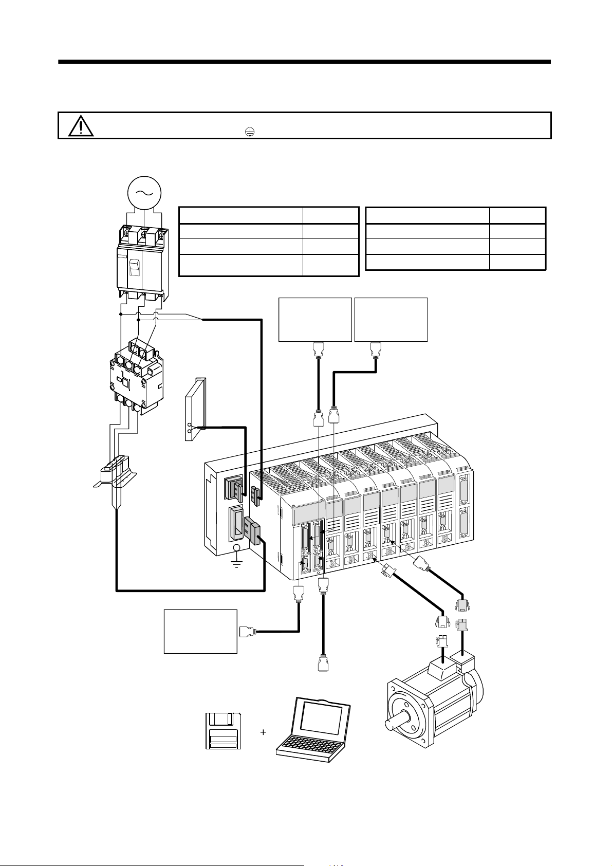
1.8 Servo system with auxiliary equipment
WARNING
3-phase 200V to 230VAC
power supply
(Note) 1-phase 200V to 230VAC
No-fuse
breaker
(NFB) or
fuse
Magnetic
contactor
(MC)
To prevent an electric shock, always connect the protective earth (PE) terminal
(terminal marked
Options and auxiliary equipment
No-fuse breaker
Magnetic contactor
MR Configurator
(servo configuration software)
11
L
L
21
Regenerative brake
option
Control circuit
power supply
) of the base unit to the protective earth (PE) of the control box.
Reference
Section 12.2.2
Section 12.2.2
Section 12.1.4
Command device
(For 1 to 4 slots)
To CN1A
Options and auxiliary equipment
Regenerative brake option
Cables
Power factor improving reactor
Command device
(For 5 to 8 slots)
To CN1B
Reference
Section 12.1.1
Section 12.2.1
Section 12.2.3
Powe
acto
improving
reacto
(FR-BAL)
L1
L2
3
L
Main circuit power supply
P
C
Machine contact
MR Configurator
(servo configuration software
MRZJW3-SETUP151E or later)
To CNP1A
To CNP3
To CNP1B
Encoder cable
To CN3
To CN5
Power supply lead
Personal computer
Note. For 1-phase 200 to 230VAC, connect the power supply to L1, L2 and leave L3 open.
1 - 9
Page 27

1. FUNCTIONS AND CONFIGURATION
MEMO
1 - 10
Page 28
2. INSTALLATION AND START UP
2. INSTALLATION AND START UP
Stacking in excess of the limited number of products is not allowed.
Install the equipment to incombustibles. Installing them directly or close to
combustibles will led to a fire.
Install the equipment in a load-bearing place in accordance with this Instruction
Manual.
Do not get on or put heavy load on the equipment to prevent injury.
Use the equipment within the specified environmental condition range.
Provide an adequate protection to prevent screws, metallic detritus and other
CAUTION
conductive matter or oil and other combustible matter from entering each unit.
Do not block the intake/exhaust ports of each unit. Otherwise, a fault may occur.
Do not subject each unit to drop impact or shock loads as they are precision
equipment.
Do not install or operate a faulty unit.
When the product has been stored for an extended period of time, consult
Mitsubishi.
When treating the servo amplifier, be careful about the edged parts such as the
corners of the servo amplifier.
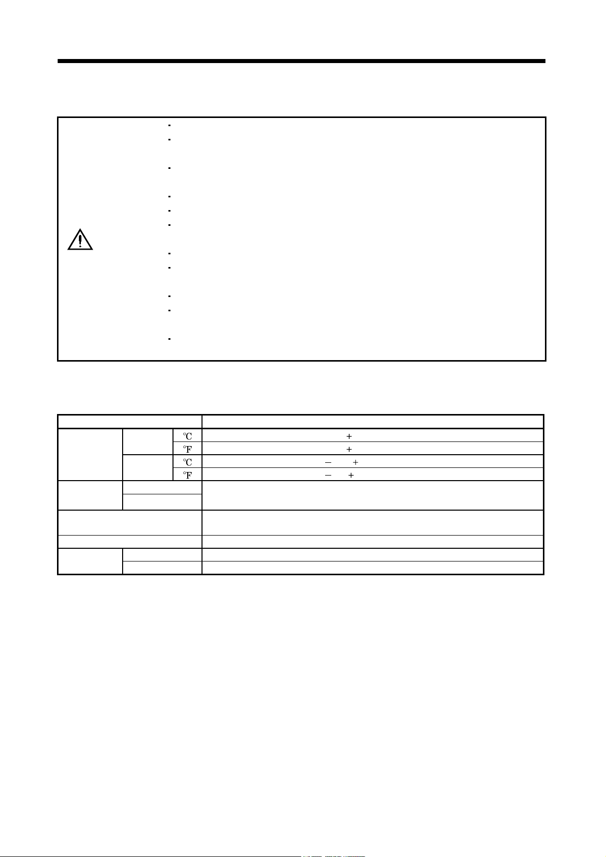
2.1 Environmental conditions
The following environmental conditions are common to the drive unit, interface unit and base unit.
Environment Conditions
During
Ambient
temperature
Ambient
humidity
Ambience
Altitude Max. 1000m (3280 ft) above sea level
Vibration
operation
In storage
During operation
In storage
[ ]0 to 55 (non-freezing)
] 32 to 131 (non-freezing)
[
[ ] 20 to 65 (non-freezing)
] 4 to 149 (non-freezing)
[
90%RH or less (non-condensing)
Indoors (no direct sunlight)
Free from corrosive gas, flammable gas, oil mist, dust and dirt
[m/s2] 5.9 [m/s2] or less
2
[ft/s
] 19.4 [ft/s2] or less
2 - 1
Page 29
2. INSTALLATION AND START UP
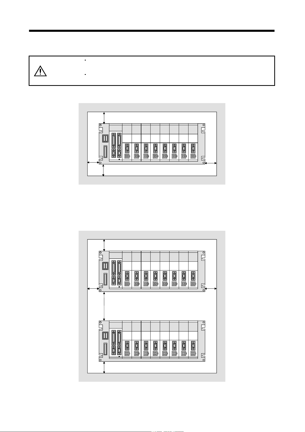
2.2 Installation direction and clearances
The equipment must be installed in the specified direction. Otherwise, a fault may
CAUTION
(1) Installation of one MELSERVO-J2M
occur.
Leave specified clearances between each unit and control box inside walls or other
equipment.
40mm(1.57inch) or more
40mm(1.57inch) or more
40mm(1.57inch) or more
40mm(1.57inch) or more
(2) Installation of two or more MELSERVO-J2M
When installing two units vertically, heat generated by the lower unit influences the ambient
temperature of the upper unit. Suppress temperature rises in the control box so that the temperature
between the upper and lower units satisfies the environmental conditions. Also provide adequate
clearances between the units or install a fan.
40mm(1.57inch) or more
40mm(1.57inch) or more
Leave 100mm(3.94inch) or more
clearance or install fan for forced air cooling.
40mm(1.57inch) or more
40mm(1.57inch) or more
2 - 2
Page 30

2. INSTALLATION AND START UP
(3) Others
When using heat generating equipment such as the regenerative brake option, install them with full
consideration of heat generation so that MELSERVO-J2M is not affected.
Install MELSERVO-J2M on a perpendicular wall in the correct vertical direction.
2.3 Keep out foreign materials
(1) When installing the unit in a control box, prevent drill chips and wire fragments from entering each
unit.
(2) Prevent oil, water, metallic dust, etc. from entering each unit through openings in the control box or a
fan installed on the ceiling.
(3) When installing the control box in a place where there are much toxic gas, dirt and dust, conduct an
air purge (force clean air into the control box from outside to make the internal pressure higher than
the external pressure) to prevent such materials from entering the control box.
2.4 Cable stress
(1) The way of clamping the cable must be fully examined so that flexing stress and cable's own mass
stress are not applied to the cable connection.
(2) For use in any application where the servo motor moves, fix the cables (encoder, power supply, brake)
supplied with the servo motor, and flex the optional encoder cable or the power supply and brake
wiring cables. Use the optional encoder cable within the flexing life range. Use the power supply and
brake wiring cables within the flexing life of the cables.
(3) Avoid any probability that the cable sheath might be cut by sharp chips, rubbed by a machine corner
or stamped by workers or vehicles.
(4) For installation on a machine where the servo motor will move, the flexing radius should be made as
large as possible. Refer to section 11.4 for the flexing life.
2 - 3
Page 31

2. INSTALLATION AND START UP
2.5 Mounting method
(1) Base unit
As shown below, mount the base unit on the wall of a control box or like with M5 screws.
Wall
(2) Interface unit/drive unit (MR-J2M-40DU or less)
The following example gives installation of the drive unit to the base unit. The same also applies to the
interface unit.
Sectional view
Drive unit
Base unit
Catch
1) Hook the catch of the drive unit in the positioning hole of the base unit.
Sectional view
2)
Drive unit
Wall
1)
Positioning hole
Base unit
Wall
2) Using the catch hooked in the positioning hole as a support, push the drive unit in.
2 - 4
Page 32

2. INSTALLATION AND START UP
Sectional view
3)
3)
3) Tighten the M4 screw supplied for the base unit to fasten the drive unit to the base unit.
POINT
Securely tighten the drive unit fixing screw.
Sectional view
Wall
Wall
(3) Drive unit (MR-J2M-70DU)
When using the MR-J2M-70DU, install it on two slots of the base unit. The slot number of this drive
unit is that of the left hand side slot of the two occupied slots, when they are viewed from the front of
the base unit.
2 - 5
Page 33

2. INSTALLATION AND START UP
2.6 When switching power on for the first time
Before starting operation, check the following:
(1) Wiring
(a) Check that the control circuit power cable, main circuit power cable and servo motor power cable
are fabricated properly.
(b) Check that the control circuit power cable is connected to the CNP1B connector and the main
circuit power cable is connected to the CNP3 connector.
(c) Check that the servo motor power cable is connected to the drive unit CNP2 connector.
(d) Check that the base unit is earthed securely. Also check that the drive unit is screwed to the base
unit securely.
(e) When using the regenerative brake option, check that the cable using twisted wires is fabricated
properly and it is connected to the CNP1A connector properly.
(f) When the MR-J2M-70DU is used, it is wired to have the left-hand side slot number of the two slots.
(g) 24VDC or higher voltages are not applied to the pins of connector CN3.
(h) SD and SG of connector CN1A
(i) The wiring cables are free from excessive force.
(j) Check that the encoder cable and servo motor power cable connected to the drive unit are connected
to the same servo motor properly.
(k) When stroke end limit switches are used, the signals across LSP
during operation.
CN1B CN3 CN4A CN4B and CN5 are not shorted.
-SG and LSN -SG are on
(2) Parameters
(a) Check that the drive unit parameters are set to correct values using the servo system controller
screen or MR Configurator (servo configuration software).
(b) Check that the interface unit parameters are set to correct values using the interface unit display
or MR Configurator (servo configuration software).
(3) Environment
Signal cables and power cables are not shorted by wire offcuts, metallic dust or the like.
(4) Machine
(a) The screws in the servo motor installation part and shaft-to-machine connection are tight.
(b) The servo motor and the machine connected with the servo motor can be operated.
2 - 6
Page 34

2. INSTALLATION AND START UP
2.7 Start up
Do not operate the switches with wet hands. You may get an electric shock.
Do not operate the controller with the front cover removed. High-voltage terminals
WARNING
CAUTION
and charging area exposed and you may get an electric shock.
During power-on or for some time after power-off, do not touch or close a parts
(cable etc.) to the regenerative brake resistor, servo motor, etc. Their temperatures
may be high and you may get burnt or a parts may damaged.
Before starting operation, check the parameters. Some machines may perform
unexpected operation.
Take safety measures, e.g. provide covers, to prevent accidental contact of hands
and parts (cables, etc.) with the servo amplifier heat sink, regenerative brake
resistor, servo motor, etc.since they may be hot while power is on or for some time
after power-off. Their temperatures may be high and you may get burnt or a parts
may damaged.
During operation, never touch the rotating parts of the servo motor. Doing so can
cause injury.
Connect the servo motor with a machine after confirming that the servo motor operates properly alone.
2 - 7
Page 35

2. INSTALLATION AND START UP
(1) Power on
Switching on the main circuit power/control circuit power places the interface unit display in the scroll
status as shown below.
In the absolute position detection system, first power-on results in the absolute position lost (A.25)
alarm and the servo system cannot be switched on. This is not a failure and takes place due to the
uncharged capacitor in the encoder.
The alarm can be deactivated by keeping power on for a few minutes in the alarm status and then
switching power off once and on again.
Also in the absolute position detection system, if power is switched on at the servo motor speed of
500r/min or higher, position mismatch may occur due to external force or the like. Power must
therefore be switched on when the servo motor is at a stop.
(2) Test operation
Using JOG operation in the test operation mode, make sure that the servo motor operates. (Refer to
Section 6.8.2.)
(3) Parameter setting
Set the parameters according to the structure and specifications of the machine. Refer to Chapter 5 for
the parameter definitions.
After setting the parameters, switch power off once.
2 - 8
Page 36

2. INSTALLATION AND START UP
(4) Slot number confirmation
Confirm the slot number in the interface unit display section of the installed drive unit.
For MR-J2M-BU4
Display
Slot number
Drive unit status
Slot number
First slot
Second slot
Third slot
Fourth slot
(5) Servo-on
Switch the servo-on in the following procedure:
1) Switch on main circuit/control power supply.
2) Turn on the servo-on (SON
).
When the servo-on status is established, operation is enabled and the servo motor is locked. At
this time, the interface unit displays "@
d@". (@ represents the slot number.)
(6) Command pulse input
Entry of a pulse train from the positioning device rotates the servo motor. At first, run it at low speed
and check the rotation direction, etc. If it does not run in the intended direction, check the input
signal.
On the status display, check the speed, command pulse frequency, load factor, etc. of the servo motor.
When machine operation check is over, check automatic operation with the program of the positioning
device.
This servo amplifier has a real-time auto tuning function under model adaptive control. Performing
operation automatically adjusts gains. The optimum tuning results are provided by setting the
response level appropriate for the machine in DRU parameter No. 2. (Refer to chapter 7.)
(7) Home position return
Make home position return as required.
2 - 9
Page 37

2. INSTALLATION AND START UP
(8) Stop
In any of the following statuses, the servo amplifier interrupts and stops the operation of the servo
motor:
Refer to Section 3.8, (2) for the servo motor equipped with electromagnetic brake. Note that the stop
pattern of forward rotation stroke end (LSP
below.
(a) Servo-on (SON
The base circuit is shut off and the servo motor coasts.
(b) Alarm occurrence
When an alarm occurs, the base circuit is shut off and the dynamic brake is operated to bring the
servo motor to a sudden stop.
(c) Forced stop (EMG_
The base circuit is shut off and the dynamic brake is operated to bring the servo motor to a sudden
stop. Servo forced stop warning (A.E6) occurs.
(d) Forward rotation stroke end (LSP
The droop pulse value is erased and the servo motor is stopped and servo-locked. It can be run in
the opposite direction.
) OFF
) OFF
) reverse rotation stroke end (LSN ) OFF is as described
) reverse rotation stroke end (LSN ) OFF
POINT
A sudden stop indicates deceleration to a stop at the deceleration time
constant of zero.
2 - 10
Page 38

3. SIGNALS AND WIRING
3. SIGNALS AND WIRING
Any person who is involved in wiring should be fully competent to do the work.
Before starting wiring, make sure that the voltage is safe in the tester more than 10
minutes after power-off. Otherwise, you may get an electric shock.
WARNING
Ground the base unit and the servo motor securely.
Do not attempt to wire each unit and servo motor until they have been installed.
Otherwise, you may get an electric shock.
The cables should not be damaged, stressed excessively, loaded heavily, or
pinched. Otherwise, you may get an electric shock.
Wire the equipment correctly and securely. Otherwise, the servo motor may
misoperate, resulting in injury.
Connect cables to correct terminals to prevent a burst, fault, etc.
Ensure that polarity ( , ) is correct. Otherwise, a burst, damage, etc. may occur.
The surge absorbing diode installed to the DC relay designed for control output
should be fitted in the specified direction. Otherwise, the signal is not output due to
a fault, disabling the forced stop and other protective circuits.
Interface unit
Interface unit
CAUTION
VIN
SG
Control output
signal
Control output
VIN
SG
signal
RARA
Use a noise filter, etc. to minimize the influence of electromagnetic interference,
which may be given to electronic equipment used near each unit.
Do not install a power capacitor, surge suppressor or radio noise filter (FR-BIF
option) with the power line of the servo motor.
When using the regenerative brake resistor, switch power off with the alarm signal.
Otherwise, a transistor fault or the like may overheat the regenerative brake
resistor, causing a fire.
Do not modify the equipment.
3 - 1
Page 39

3. SIGNALS AND WIRING
3.1 Control signal line connection example
POINT
Refer to Section 3.4 for connection of the power supply line and to Section
3.5 for connection with servo motors.
(Note 2)
RA
(Note 13)
Symbol
MR-J2M-P8A
CN1A(Note 4)
Slot 1 Slot 2 Slot 3 Slot 4
11 33 6 28RD
Positioning module
QD70
CON1
Slot 1 Slot 2 Slot 3 Slot 4
A1
B1
A16A14B16B14
A15A13B15B13
A6A3B6B3
A7A4B7B4
B2 B5
B18
B20 A18
B17 B19
A2 A5
A20
A17 A19
CON2 (Note 13)
Slot 5 Slot 6 Slot 7 Slot 8
A16
A14B16B14
A15
A13B15B13
A6A3B6B3
A7
A4B7B4
A5
A2B5B2
B18
B20 A18
B17 B19
A20
A17 A19
24VDC
power
supply
(Note 13)
Symbol
24G
24V
CLEAR COM
CLEAR
PULSE COM
PULSE F
PULSE R
PG COM
PG
Symbol
CLEAR COM
CLEAR
PULSE COM
PULSE F
PULSE R
PG COM
PG
(Note 7)
(Note 2)
(Note 7)
RA
RA
INP
ALM_A
SON
RES
LG
(Note 8)
P5
OP_VIN
SG
VIN
OPC
CR
PG
PP
NG
NP
OP
OP_COM
SD
(Note 13) CN1B(Note 4)
Symbol
RA
RA
RA
RD
INP
ALM_B
SON
RES
LG
(Note 8)
P5
OP_VIN
SG
VIN
OPC
CR
PG
PP
NG
NP
OP
OP_COM
SD
358303
27
371210
36
32
5
31
4
9
21, 46, 50
49
47
1
26
2
34
29
7
3844 42 40
1319 17 15
3945 43 41
1420 18 16
2225 24 23
48
Plate
Slot 5 Slot 6 Slot 7 Slot 8
11 33 6
28
358303
27
32
31
5
4
37
36
9
21, 46, 50
49
47
1
26
2
121034
29
7
3844 42 40
1319 17 15
3945 43 41
1420 18 16
2225 24 23
48
Plate
3 - 2
Page 40

3. SIGNALS AND WIRING
(Note 9)
MR Configurator
(servo
configuration
software)
Personal computer
CN3
(Note 5)CN3
4MO1
A
10k
(Note 6)
(Note 6)
(Note 3, 6)
Communication
cable
(Note 13)
Symbol
LSP
LSN
SG
(Note 13)
Symbol Slot 5
LSP
LSN
Symbol Slot 1 to 8
EMG_A
EMG_B
CN5
Slot 1 Slot 2 Slot 3 Slot 4
1
3
5
2
4
6
10
8
CN5
Slot 6 Slot 7 Slot 8
111213
CN5
20
19
14
MR-J2M-P8A
151617
18
14 MO2
7MO3
7
11 LG
Plate
SD
Base unit
CON3A
(Slot 1)
CON3B
(Slot 2)
CON3H
(Slot 8)
A
A
(Note 12)
10k
Monitor
output
Max. +1mA
meter
10k
Zero-center
Drive unit
(Note 5) CN2
Drive unit
(Note 5) CN2
Drive unit
(Note 5) CN2
(Note 11)
Battery unit
MR-J2M-BT
MR-J2MBTCBL M
CON4
(Note 1)
(Note 10)MR-J2M-D01
CN4A
CN4B
3 - 3
Page 41

3. SIGNALS AND WIRING
Note 1. To prevent an electric shock, always connect the protective earth (PE) terminal (terminal marked ) of the base unit to the
protective earth (PE) of the control box.
2. Connect the diode in the correct direction. If it is connected reversely, the servo amplifier will be faulty and will not output signals,
disabling the forced stop and other protective circuits.
3. The forced stop switch (normally closed contact) must be installed.
4. CN1A
5. CN2 and CN3 have the same shape. Wrong connection of the connectors can cause a fault.
6. When starting operation, always connect the forced stop (EMG_A) and forward/reverse rotation stroke end (LSN
7. Trouble (ALM_
8. Always connect P5-OP_VIN when using the 5V output (P5). Keep them open when supplying external power.
9. Use MRZJW3-SETUP151E.
10. Refer to Section 3.3 for the MR-J2M-D01 extension IO unit.
11. The MR-J2M-BT battery unit is required to configure an absolute position detection system. Refer to Chapter 14 for details.
12. When connecting the personal computer together with monitor outputs 1, 2, use the maintenance junction card (MR-J2CN3TM).
13.
CN1B, CN4A CN4B have the same shape. Wrong connection of the connectors will lead to a fault.
/LSP ) with
SG. (Normally closed contacts)
) is connected with COM in normal alarm-free condition. When this signal is switched off (at occurrence of an
alarm), the output of the programmable controller should be stopped by the sequence program.
(Refer to Section 12.1.2)
in Symbol indicates a slot number.
3 - 4
Page 42

3. SIGNALS AND WIRING
3.2 I/O signals of interface unit
3.2.1 Connectors and signal arrangements
POINT
The connector pin-outs shown above are viewed from the cable connector
wiring section side.
(1) Signal arrangement
CN1BCN1A
2
OPC
4
RES4
6
RD3
8
INP2
10
SON2
12
CR1
14
NP4
16
NP3
18
NP2
20
NP1
22
OP4
24
OP2
1
SG
3
INP4
5
SON4
7
CR3
9
RES2
11
RD1
13
PP4
15
PP3
17
PP2
19
PP1
21
LG
23
OP3
25
OP1
27
ALM_A
29
CR4
31
RES3
33
RD2
35
INP1
37
SON1
39
NG4
41
NG3
43
NG2
45
NG1
47
OP_VIN
49
P5
26
VIN
28
RD4
30
INP3
32
SON3
34
CR2
36
RES1
38
PG4
40
PG3
42
PG2
44
PG1
46
LG
48
OP_COM
50
LG
MR-J2M-P8A
2
OPC
4
RES8
6
RD7
8
INP6
10
SON6
12
CR5
14
NP8
16
NP7
18
NP6
20
NP5
22
OP8
24
OP6
1
SG
3
INP8
5
SON8
7
CR7
9
RES6
11
RD5
13
PP8
15
PP7
17
PP6
19
PP5
21
LG
23
OP7
25
OP5
27
ALM_B
29
CR8
31
RES7
33
RD6
35
INP5
37
SON5
39
NG8
41
NG7
43
NG6
45
NG5
47
OP_VIN
49
P5
26
VIN
28
RD8
30
INP7
32
SON7
34
CR6
36
RES5
38
PG8
40
PG7
42
PG6
44
PG5
46
LG
48
OP_COM
50
LG
2
LSN1
4
LSN2
6
LSN3
8
SG
10
LSN4
1
LSP1
3
LSP2
5
LSP3
7
LSP4
9
CN5
12
LSN5
14
LSN6
16
LSN7
18
LSN8
20
EMG_A
11
LSP5
13
LSP6
15
LSP7
17
LSP8
19
EMG_B
The connector frames are
connected with the PE (earth)
terminal inside the servo amplifier.
3 - 5
2
RXD
4
MO1
6
8
10
TRE
1
LG
3
LG
5
RDP
7
MO3
9
SDP
CN3
12
TXD
14
MO2
16
18
20
P5
11
LG
13
15
RDN
17
19
SDN
Page 43

3. SIGNALS AND WIRING
3.2.2 Signal explanations
For the I/O interfaces (symbols in I/O column in the table), refer to Section 3.2.5.
The pin No.s in the connector pin No. column are those in the initial status.
(1) Input signals
Signal Symbol
Servo-on 1 SON 1 CN1A-37
Servo-on 2 SON 2 CN1A-10
Servo-on 3 SON 3 CN1A-32
Servo-on 4 SON 4 CN1A-5
Servo-on 5 SON 5 CN1B-37
Servo-on 6 SON 6 CN1B-10
Servo-on 7 SON 7 CN1B-32
Servo-on 8 SON 8 CN1B-5
Reset 1 RES 1 CN1A-36
Reset 2 RES 2 CN1A-9
Reset 3 RES 3 CN1A-31
Reset 4 RES 4 CN1A-4
Reset 5 RES 5 CN1B-36
Reset 6 RES 6 CN1B-9
Reset 7 RES 7 CN1B-31
Reset 8 RES 8 CN1B-4
Connector
pin No.
Functions/Applications I/O division
SON 1: Servo-on signal for slot 1
SON 2: Servo-on signal for slot 2
SON 3: Servo-on signal for slot 3
SON 4: Servo-on signal for slot 4
SON 5: Servo-on signal for slot 5
SON 6: Servo-on signal for slot 6
SON 7: Servo-on signal for slot 7
SON 8: Servo-on signal for slot 8
Connect SON
amplifier ready to operate (servo-on).
Disconnect SON
motor (servo off).
RES 1: Reset signal for slot 1
RES 2: Reset signal for slot 2
RES 3: Reset signal for slot 3
RES 4: Reset signal for slot 4
RES 5: Reset signal for slot 5
RES 6: Reset signal for slot 6
RES 7: Reset signal for slot 7
RES 8: Reset signal for slot 8
Disconnect RES
Some alarms cannot be deactivated by the reset (RES
Section 9.2.
Shorting RES
The base circuit is not shut off when "
parameter No. 51 (Function selection 6).
-SG to switch on the base circuit and make the servo
-SG to shut off the base circuit and coast the servo
-SG for more than 50ms to reset the alarm.
-SG in an alarm-free status shuts off the base circuit.
1 " is set in DRU
. Refer to
)
DI-1
DI-1
3 - 6
Page 44

3. SIGNALS AND WIRING
Signal Symbol
Forward rotation
stroke end 1
Forward rotation
stroke end 2
Forward rotation
stroke end 3
Forward rotation
stroke end 4
Forward rotation
stroke end 5
Forward rotation
stroke end 6
Forward rotation
stroke end 7
Forward rotation
stroke end 8
Reverse rotation
stroke end 1
Reverse rotation
stroke end 2
stroke end 3
Reverse rotation
stroke end 4
stroke end 5
stroke end 6
Reverse rotation
stroke end 7
Reverse rotation
stroke end 8
Forced stop A EMG_A CN5-20 EMG_A: Forced stop signal for slots 1 to 8
Forced stop B EMG_B CN5-19 EMG_B: Forced stop signal for slots 1 to 8
LSP 1 CN5-1
LSP 2 CN5-3
LSP 3 CN5-5
LSP 4 CN5-7
LSP 5 CN5-11
LSP 6 CN5-13
LSP 7 CN5-15
LSP 8 CN5-17
LSN 1 CN5-2
LSN 2 CN5-4
LSN 3 CN5-6
LSN 4 CN5-10
LSN 5 CN5-12
LSN 6 CN5-14
LSN 7 CN5-16
LSN 8 CN5-18
Connector
pin No.
Functions/Applications I/O division
LSP 1: Forward rotation stroke end signal for slot 1
LSP 2: Forward rotation stroke end signal for slot 2
LSP 3: Forward rotation stroke end signal for slot 3
LSP 4: Forward rotation stroke end signal for slot 4
LSP 5: Forward rotation stroke end signal for slot 5
LSP 6: Forward rotation stroke end signal for slot 6
LSP 7: Forward rotation stroke end signal for slot 7
LSP 8: Forward rotation stroke end signal for slot 8
LSN 1: Reverse rotation stroke end signal for slot 1
LSN 2: Reverse rotation stroke end signal for slot 2
LSN 3: Reverse rotation stroke end signal for slot 3
LSN 4: Reverse rotation stroke end signal for slot 4
LSN 5: Reverse rotation stroke end signal for slot 5
LSN 6: Reverse rotation stroke end signal for slot 6
LSN 7: Reverse rotation stroke end signal for slot 7
LSN 8: Reverse rotation stroke end signal for slot 8
To start operation, short LSP
bring the motor to a sudden stop and make it servo-locked.
1" in parameter No. 22 (Function selection 4) to make a
Set "
slow stop.
(Refer to Section 5.1.2.)
(Note) Input signals OperationReverse rotation
LSP LSN CCW
directionCWdirection
11
01Reverse rotation
10
00Reverse rotation
Note. 0: LSP
1: LSP
Disconnect EMG_
which the servo is switched off and the dynamic brake is operated.
Connect EMG_
When either of EMG-A and EMG-B is to be used, short the unused
signal with SG.
/LSN -SG off (open)
/LSN -SG on (short)
-SG to bring the servo motor to forced stop state, in
-SG in the forced stop state to reset that state.
-SG and/or LSN -SG. Open them to
DI-1
DI-1
3 - 7
Page 45

3. SIGNALS AND WIRING
PP 1
PG 1
PP 2
PG 2
PP 3
PG 3
PP 4
PG 4
PP 5
PG 5
PP 6
PG 6
PP 7
PG 7
PP 8
PG 8
Connector
pin No.
CN1A-19
CN1A-20
CN1A-44
CN1A-45
CN1A-17
CN1A-18
CN1A-42
CN1A-43
CN1A-15
CN1A-16
CN1A-40
CN1A-41
CN1A-13
CN1A-14
CN1A-38
CN1A-39
CN1B-19
CN1B-20
CN1B-44
CN1B-45
CN1B-17
CN1B-18
CN1B-42
CN1B-43
CN1B-15
CN1B-16
CN1B-40
CN1B-41
CN1B-13
CN1B-14
CN1B-38
CN1B-39
Signal Symbol
Clear 1 CR 1 CN1A-12
Clear 2 CR 2 CN1A-34
Clear 3 CR 3 CN1A-7
Clear 4 CR 4 CN1A-29
Clear 5 CR 5 CN1B-12
Clear 6 CR 6 CN1B-34
Clear 7 CR 7 CN1B-7
Clear 8 CR 8 CN1B-29
Forward rotation
pulse train 1
Reverse rotation
pulse train 1
Forward rotation
pulse train 2
Reverse rotation
pulse train 2
Forward rotation
pulse train 3
Reverse rotation
pulse train 3
Forward rotation
pulse train 4
Reverse rotation
pulse train 4
Forward rotation
pulse train 5
Reverse rotation
pulse train 5
Forward rotation
pulse train 6
Reverse rotation
pulse train 6
Forward rotation
pulse train 7
Reverse rotation
pulse train 7
Forward rotation
pulse train 8
Reverse rotation
pulse train 8
NP 1
NG 1
NP 2
NG 2
NP 3
NG 3
NP 4
NG 4
NP 5
NG 5
NP 6
NG 6
NP 7
NG 7
NP 8
NG 8
Functions/Applications I/O division
CR 1: Clear signal for slot 1
CR 2: Clear signal for slot 2
CR 3: Clear signal for slot 3
CR 4: Clear signal for slot 4
CR 5: Clear signal for slot 5
CR 6: Clear signal for slot 6
CR 7: Clear signal for slot 7
CR 8: Clear signal for slot 8
Connect CR
leading edge. The pulse width should be 10ms or more.
When the DRU parameter No.42 (Input signal selection 1) setting is "
", the pulses are always cleared while CR -SG are connected.
PP 1 NP 1 PG 1 NG 1: Forward/reverse rotation pulse train for slot 1
PP 2 NP 2 PG 2 NG 2: Forward/reverse rotation pulse train for slot 2
PP 3 NP 3 PG 3 NG 3: Forward/reverse rotation pulse train for slot 3
PP 4 NP 4 PG 4 NG 4: Forward/reverse rotation pulse train for slot 4
PP 5 NP 5 PG 5 NG 5: Forward/reverse rotation pulse train for slot 5
PP 6 NP 6 PG 6 NG 6: Forward/reverse rotation pulse train for slot 6
PP 7 NP 7 PG 7 NG 7: Forward/reverse rotation pulse train for slot 7
PP 8 NP 8 PG 8 NG 8: Forward/reverse rotation pulse train for slot 8
Used to enter a command pulse train.
In the open collector system (max. input frequency 200kpps):
Forward rotation pulse train across PP
Reverse rotation pulse train across NP
In the differential receiver system (max. input frequency 500kpps):
Forward rotation pulse train across PG
Reverse rotation pulse train across NG -NP
The command pulse train form can be changed using DRU parameter No.
21 (Function selection 3).
-SG to clear the position control counter droop pulses on its
1
-SG
-SG
-PP
DI-1
DI-2
3 - 8
Page 46

3. SIGNALS AND WIRING
(2) Output signals
Signal Symbol
Trouble A ALM_A CN1A-27
Trouble B ALM_B CN1B-27
Ready 1 RD 1 CN1A-11
Ready 2 RD 2 CN1A-33
Ready 3 RD 3 CN1A-6
Ready 4 RD 4 CN1A-28
Ready 5 RD 5 CN1B-11
Ready 6 RD 6 CN1B-33
Ready 7 RD 7 CN1B-6
Ready 8 RD 8 CN1B-28
In position 1 INP 1 CN1A-35
In position 2 INP 2 CN1A-8
In position 3 INP 3 CN1A-30
In position 4 INP 4 CN1A-3
In position 5 INP 5 CN1B-35
In position 6 INP 6 CN1B-8
In position 7 INP 7 CN1B-30
In position 8 INP 8 CN1B-3
Encoder Z-phase
pulse 1
Encoder Z-phase
pulse 2
Encoder Z-phase
pulse 3
Encoder Z-phase
pulse 4
Encoder Z-phase
pulse 5
Encoder Z-phase
pulse 6
Encoder Z-phase
pulse 7
Encoder Z-phase
pulse 8
Analog monitor 1 MO1 CN3-4 Used to output the data set in IFU parameter No.3 (Analog monitor 1
Analog monitor 2 MO2 CN3-14 Used to output the data set in IFU parameter No.4 (Analog monitor 2
Analog monitor 3 MO3 CN3-7 Used to output the data set in IFU parameter No.5 (Analog monitor 3
OP 1 CN1A-25
OP 2 CN1A-24
OP 3 CN1A-23
OP 4 CN1A-22
OP 5 CN1B-25
OP 6 CN1B-24
OP 7 CN1B-23
OP 8 CN1B-22
Connector
pin No.
Functions/Applications I/O division
ALM_A: Alarm signal for slot 1 to 4
ALM_B: Alarm signal for slot 5 to 8
-SG are disconnected when power is switched off or the
ALM
protective circuit is activated to shut off the base circuit. Without
alarm, ALM
RD 1: Ready signal for slot 1
RD 2: Ready signal for slot 2
RD 3: Ready signal for slot 3
RD 4: Ready signal for slot 4
RD 5: Ready signal for slot 5
RD 6: Ready signal for slot 6
RD 7: Ready signal for slot 7
RD 8: Ready signal for slot 8
-SG are connected when the servo is switched on and the servo
RD
amplifier is ready to operate.
INP 1: In position signal for slot 1
INP 2: In position signal for slot 2
INP 3: In position signal for slot 3
INP 4: In position signal for slot 4
INP 5: In position signal for slot 5
INP 6: In position signal for slot 6
INP 7: In position signal for slot 7
INP 8: In position signal for slot 8
-SG are connected when the number of droop pulses is in the
INP
preset in-position range. The in-position range can be changed using
DRU parameter No. 5.
When the in-position range is increased, INP
connected during low-speed rotation.
OP 1: Encoder Z-phase pulse signal for slot 1
OP 2: Encoder Z-phase pulse signal for slot 2
OP 3: Encoder Z-phase pulse signal for slot 3
OP 4: Encoder Z-phase pulse signal for slot 4
OP 5: Encoder Z-phase pulse signal for slot 5
OP 6: Encoder Z-phase pulse signal for slot 6
OP 7: Encoder Z-phase pulse signal for slot 7
OP 8: Encoder Z-phase pulse signal for slot 8
Outputs the zero-point signal of the encoder. One pulse is output per
servo motor revolution. OP and LG are connected when the zero-point
position is reached. (Negative logic)
The minimum pulse width is about 400
using this pulse, set the creep speed to 100r/min. or less.
output) to across MO1-LG in terms of voltage. Resolution 10 bits
output) to across MO2-LG in terms of voltage. Resolution 10 bits
output) to across MO3-LG in terms of voltage. Resolution 10 bits
-SG are connected within about 3s after power on.
-SG may be kept
s. For home position return
DO-1
DO-1
DO-1
DO-2
Analog
output
Analog
output
Analog
output
3 - 9
Page 47

3. SIGNALS AND WIRING
(3) Communication
POINT
Refer to Chapter 13 for the communication function.
Signal Symbol
RS-422 I/F SDP
SDN
RDP
RDN
RS-422
termination
RS-232C I/F RXD
TRE CN3-10 Termination resistor connection terminal of RS-422 interface.
TXD
Connector
pin No.
CN3-9
CN3-19
CN3-5
CN3-15
CN3-2
CN3-12
Functions/Applications
RS-422 and RS-232C functions cannot be used together.
Choose either one in IFU parameter No. 16.
When the servo amplifier is the termination axis, connect this terminal to RDN
(CN3-15).
RS-422 and RS-232C functions cannot be used together.
Choose either one in IFU parameter No. 0.
(4) Power supply
Signal Symbol
Digital I/F power
supply input
Digital I/F
common
5V output P5 CN1A-49
Encoder Z-phase
pulse power
supply
Encoder Z-phase
pulse common
Control common LG CN1A-50
Shield SD Plate Connect the external conductor of the shield cable.
VIN CN1A-26
OP_VIN CN1A-47
OP_COM
Connector
pin No.
CN1B-26
SG CN1A-1
CN1B-1
CN5-8
CN1B-49
CN3-20
CN1B-47
CN1A-48
CN1B-48
CN1A-46
CN1A-21
CN1B-50
CN1B-46
CN1B-21
CN3-1
CN3-3
CN3-11
CN3-13
Functions/Applications
Driver power input terminal for digital interface.
Input 24VDC (300mA or more) for input interface.
24VDC
Common terminal of VIN. Pins are connected internally.
Separated from LG.
Internal power supply for encoder Z-phase pulses. Connect P5-OP_VIN when using
this power supply as an encoder Z-phase pulse common.
5VDC
Power input for encoder Z-phase pulse common. Connect P5-OP_VIN when using
the 5V output (P5) as an encoder Z-phase pulse common. Supply power to OP_VIN
when using an external power supply as an encoder Z-phase pulse common. At this
time, do not connect P5-OP_VIN.
Common for encoder Z-phase pulses. Power input to OP_VIN is output from
OP_COM.
Common terminal for MO1, MO2 and MO3.
10%
5%
3 - 10
Page 48

3. SIGNALS AND WIRING
3.2.3 Detailed description of the signals
(1) Pulse train input
(a) Input pulse waveform selection
Encoder pulses may be input in any of three different forms, for which positive or negative logic
can be chosen. Set the command pulse train form in DRU parameter No. 21.
Arrow
A- and B-phase pulse trains are imported after they have been multiplied by 4.
or in the table indicates the timing of importing a pulse train.
Pulse train form
Forward rotation
pulse train
Reverse rotation
pulse train
Pulse train sign
Negative logic
A-phase pulse train
B-phase pulse train
Forward rotation
pulse train
Reverse rotation
pulse train
Pulse train sign
Positive logic
A-phase pulse train
B-phase pulse train
Forward rotation
command
PP
NP
PP
NP
PP
NP
PP
NP
PP
NP
PP
NP
Reverse rotation
command
L
H
H
L
DRU parameter No. 21
(Command pulse train)
0010
0011
0012
0000
0001
0002
3 - 11
Page 49

3. SIGNALS AND WIRING
(b) Connections and waveforms
1) Open collector system
Connect as shown below:
The explanation assumes that the input waveform has been set to the negative logic and forward
and reverse rotation pulse trains (DRU parameter No.21 has been set to 0010). The waveforms
in the table in (a), (1) of this section are voltage waveforms of PP
relationships with transistor ON/OFF are as follows:
24VDC
Servo amplifier
OPC
PP
NP
SD
Approx. 1.2k
Approx. 1.2k
and NP based on SG. Their
Forward rotation
pulse train
(transistor)
Reverse rotation
pulse train
(transistor)
(OFF)
Forward rotation command Reverse rotation command
(ON)
(OFF)
(ON)
(OFF)(ON)
(ON) (OFF) (ON) (OFF) (ON)(OFF)
3 - 12
Page 50

3. SIGNALS AND WIRING
2) Differential line driver system
Connect as shown below:
The explanation assumes that the input waveform has been set to the negative logic and forward
and reverse rotation pulse trains (DRU parameter No.21 has been set to 0010).
For the differential line driver, the waveforms in the table in (a), (1) of this section are as follows.
The waveforms of PP
line driver.
Servo amplifier
PP
PG
NP
NG
SD
, PG , NP and NG are based on that of the ground of the differential
Forward rotation
pulse train
PP
PG
Reverse rotation
pulse train
NP
NG
Forward rotation command Reverse rotation command
3 - 13
Page 51

3. SIGNALS AND WIRING
A
(2) In-position (INP )
PF-SG are connected when the number of droop pulses in the deviation counter falls within the preset
in-position range (DRU parameter No. 5). INP
is performed with a large value set as the in-position range.
-SG may remain connected when low-speed operation
(3) Ready (RD )
Servo-on(SON )
larm
Droop pulses
In position(INP )
Servo-on(SON )
Alarm
Ready(RD )
ON
OFF
Yes
No
ON
OFF
ON
OFF
Yes
No
ON
OFF
In-position range
100ms less 10ms less 10ms less
3 - 14
Page 52

3. SIGNALS AND WIRING
3.2.4 Internal connection diagram
(Note)
CN1A
symbol
VIN
SG
SON
CR
RES
OPC
PG
PP
NG
NP
SD
(Note)
symbol
OPC
PG
PP
NG
NP
VIN
SG
SON
CR
RES
SD
slot 2 slot 3 slot 4
slot 1
26
1
371210
34
36
32
31
9
5
29
7
4
2
44
19
45
20
42
17
43
18
40
15
41
16
38
13
39
14
Plate
slot 5 slot 6 slot 7 slot 8
2
44
19
45
20
42
17
43
18
40
15
41
16
38
13
39
14
26
1
371210
36
34
32
9
31
5
29
7
4
Plate
Approx.6.8k
Approx.6.8k
Approx.100
Approx.100
Approx.100
Approx.100
Approx.6.8k
Approx.6.8k
MR-J2M-P8A
Approx.1.2k
Approx.1.2k
Approx.1.2k
Approx.1.2k
5V
5VDC
slot 2 slot 3 slot 4
slot 1
113533
8
25
24
21, 46, 50
slot 6 slot 7 slot 8
slot 5
253524
21, 46, 50
33
11
8
27
49
47
48
Plate
47
48
49
27
Plate
30
23
23
30
CN1A
(Note)
symbol
ALM_A
28
6
6
RD
3
INP
22
OP
LG
P5
OP_VIN
OP_COM
SD
(Note)
CN1BCN1B
symbol
OP_VIN
OP_COM
P5
22
OP
LG
ALM_B
RD
28
INP
3
SD
CN5
symbol
EMG_A
EMG_B
CN5
(Note)
symbol
slot 1 slot 2 slot 3 slot 4
LSP
LSN
(Note)
CN5
symbol
slot 5 slot 6 slot 7 slot 8
LSP
LSN
SG
slot 1 to 8
20
19
1357
24 10
6
11 13 15 17
12 14 16 18
8
Note. in Symbol indicates the slot number.
Approx.6.8k
Approx.6.8k
Approx.6.8k
Approx.6.8k
Approx.6.8k
Approx.6.8k
3 - 15
CN3
Plate
12
19
15
MO1
4
MO2
14
MO3
7
LG
11
SD
TXD
RXD
2
SDP
9
SDN
RDP
5
RDN
Page 53

3. SIGNALS AND WIRING
t
3.2.5 Interface
(1) Common line
The following diagram shows the power supply and its common line.
Interface unit
INP , etc.
MO1
MO2
MO3
DI-1
24VDC
VIN
SON , etc.
SG
RA
SD
Analog monitor output
(Note)
Base unit
OPC
PG NG
PG NP
SG
SD
Drive unit
Extension IO unit
LG
SDP
SDN
RDP
RDN
LG
TXD
RXD
MR
MRR
LG
SD
LA, etc.
LAR, etc.
LG
SD
RS-232C
Servo motor encoder
E
RS-422
Servo motor
M
Differential line driver outpu
35mA max.
Ground
DI-1
Note. Assumes a differential line driver pulse train input.
SG
EM1
24VDC
3 - 16
MBR
VIN
RA
Page 54

3. SIGNALS AND WIRING
(2) Detailed description of the interfaces
This section gives the details of the I/O signal interfaces (refer to I/O Division in the table) indicated in
Sections 3.2.2.
Refer to this section and connect the interfaces with the external equipment.
(a) Digital input interface DI-1
Give a signal with a relay or open collector transistor.
Interface unit
24VDC
300mA or more
VIN
R: Approx. 4.7k
For transistor
Approx. 5mA
TR
VCES 1.0V
I
CE0 100 A
SON
etc.
Switch
SG
(b) Digital output interface DO-1
A lamp, relay or photocoupler can be driven. Provide a diode (D) for an inductive load, or an inrush
current suppressing resister (R) for a lamp load. (Permissible current: 40mA or less, inrush
current: 100mA or less)
1) Inductive load
Interface unit
VIN
ALM_
Load
etc.
24VDC
10%
2) Lamp load
SG
Interface unit
ALM_
etc.
VIN
SG
Opposite polarity of diode
will fail interface unit.
R
3 - 17
24VDC
10%
Page 55

3. SIGNALS AND WIRING
A
(c) Pulse train input interface DI-2
Give a pulse train signal in an open collector or differential line driver system.
1) Open collector system
Interface unit
PP
24VDC
2m(78.74in)
or less
0.9
0.1
OPC
Max. input pulse
frequency 200kpps
PP , NP
SD
tHL
tc
Approx.
1.2k
tLH tHL 0.2 s
tc 2 s
tF 3 s
NP
2) Differential line driver system
10m (393.70in) or less
m26LS31 or equivalent
PP PG
0.9
0.1
tc tLH
tc tLH
tc
tF
Interface unit
Max. input pulse
frequency 500kpps
PP (NP )
PG (NG )
SD
tHL
About 100
tF
tLH tHL 0.1 s
tc 0.7 s
tF 3 s
NP NG
3 - 18
Page 56

3. SIGNALS AND WIRING
r
(d) Encoder pulse output DO-2
1) Open collector system
Max. intake current 35mA
Interface unit Interface unit
OP
LG
SD
2) Differential line driver system
Max. output current 35mA
extension IO unit extension IO unit
LA
(LB , LZ )
LAR
(LBR , LZR )
LG
SD SD
Am26LS32 or equivalent
150
(LBR , LZR )
LA
(LB , LZ )
LAR
OP
LG
SD
5 to 24VDC
100
Photocoupler
High-speed
photocouple
(e) Analog output
Output voltage:
4V
Max. output current: 0.5mA
Resolution: 10bit
Interface unit
Sarvo motor CCW rotation
LA
LAR
LB
LBR
LZ
LZR
OP
MO
LG
T
/2
400 s or more
10k
Reading in one or both
A
directions 1mA meter.
SD
3 - 19
Page 57

3. SIGNALS AND WIRING
3.3 Signal and wiring for extension IO unit
3.3.1 Connection example
POINT
The pins without symbols can be assigned any devices using the MR
Configurator (servo configuration software).
MR-J2M-D01
VIN
SG
(Note 2)
CN4A
11, 36
12, 37
1
2
3
4
5
6
7
8
26
27
28
29
30
31
32
33
Approx. 6.8k
Approx. 6.8k
(Note 3)
24VDC
CN4B-11
(Note 2)
CN4A
10
34
35
(Note 2)
CN4A
13, 38
50
25
49
24
48
23
47
22
46
21
45
20
44
19
43
18
42
17
41
16
40
15
39 LZ4
14 LZR4
plate
LG
LA1
LAR1
LB1
LBR1
LZ1
LZR1
LA2
LAR2
LB2
LBR2
LZ2
LZR2
LA3
LAR3
LB3
LBR3
LZ3
LZR3
LA4
LAR4
LB4
LBR4
SD
(Note 1)
RA19
RA2
RA3
RA4
Encoder A-phase pulse 1
(Differential line driver system)
Encoder B-phase pulse 1
(Differential line driver system)
Encoder Z-phase pulse 1
(Differential line driver system)
Encoder A-phase pulse 2
(Differential line driver system)
Encoder B-phase pulse 2
(Differential line driver system)
Encoder Z-phase pulse 2
(Differential line driver system)
Encoder A-phase pulse 3
(Differential line driver system)
Encoder B-phase pulse 3
(Differential line driver system)
Encoder Z-phase pulse 3
(Differential line driver system)
Encoder A-phase pulse 4
(Differential line driver system)
Encoder B-phase pulse 4
(Differential line driver system)
Encoder Z-phase pulse 4
(Differential line driver system)
3 - 20
Page 58

3. SIGNALS AND WIRING
SG
VIN
(Note 2)
CN4B
1
2
3
4
5
6
7
8
26
27
28
29
30
31
32
33
12, 37
11, 36
Approx. 6.8k
Approx. 6.8k
CN4A-11
(Note 2)
CN4B
13, 38
50 LA5
25 LAR5
49 LB5
24 LBR5
48 LZ5
23 LZR5
47 LA6
22 LAR6
46 LB6
21 LBR6
45 LZ6
20 LZR6
44 LA7
19 LAR7
43 LB7
18 LBR7
42 LZ7
17 LZR7
41 LA8
16 LAR8
40 LB8
15 LBR8
39 LZ8
14 LZR8
plate
LG
Encoder A-phase pulse 5
(Differential line driver system)
Encoder B-phase pulse 5
(Differential line driver system)
Encoder Z-phase pulse 5
(Differential line driver system)
Encoder A-phase pulse 6
(Differential line driver system)
Encoder B-phase pulse 6
(Differential line driver system)
Encoder Z-phase pulse 6
(Differential line driver system)
Encoder A-phase pulse 7
(Differential line driver system)
Encoder B-phase pulse 7
(Differential line driver system)
Encoder Z-phase pulse 7
(Differential line driver system)
Encoder A-phase pulse 8
(Differential line driver system)
Encoder B-phase pulse 8
(Differential line driver system)
Encoder Z-phase pulse 8
(Differential line driver system)
SD
(Note 2)
CN4B
9
10
34
35
(Note 1)
RA7
RA8
RA9
RA10
MR-J2M-D01
Note 1. Connect the diodes in the correct orientation. Opposite connection may cause the servo amplifier to be faulty and
disable the signals from being output, making the forced stop and other protective circuits inoperative.
2. The signals having the same name are connected to the inside of the servo amplifier.
3. Always connect 24VDC (200mA).
3 - 21
Page 59

3. SIGNALS AND WIRING
3.3.2 Connectors and signal configurations
(1) Signal configurations
POINT
The pin configurations of the connectors are as viewed from the cable
connector wiring section.
The pins without symbols can be assigned any devices using the MR
Configurator (servo configuration software).
49
LB1
47
LA2
45
LZ2
43
LB3
41
LA4
39
LZ4
37
SG
35
33
31
29
27
50
LA1
48
LZ1
46
LB2
44
LA3
42
LZ3
40
LB4
38
LG
36
VIN
34
32
30
28
26
CN4A
LBR1
LAR2
LZR2
LBR3
LAR4
LZR4
24
22
20
18
16
14
12
SG
10
8
6
4
2
25
LAR1
23
LZR1
21
LBR2
19
LAR3
17
LZR3
15
LBR4
13
LG
11
VIN
9
7
5
3
1
49
LB5
47
LA6
45
LZ6
43
LB7
41
LA8
39
LZ8
37
SG
35
33
31
29
27
50
LA5
48
LZ5
46
LB6
44
LA7
42
LZ7
40
LB8
38
LG
36
VIN
34
32
30
28
26
CN4B
24
LBR5
22
LAR6
20
LZR6
18
LBR7
16
LAR8
14
LZR8
12
SG
10
8
6
4
2
25
LAR5
23
LZR5
21
LBR6
19
LAR7
17
LZR7
15
LBR8
13
LG
11
VIN
9
7
5
3
1
3 - 22
Page 60

3. SIGNALS AND WIRING
3.3.3 Signal explanations
For the IO interfaces (system in I/O column in the table), refer to section 3.2.5.
(1) Input signal
Signal Symbol
Connector
pin No.
CN4A-1
CN4A-2
CN4A-3
CN4A-4
CN4A-5
CN4A-6
CN4A-7
CN4A-8
CN4A-26
CN4A-27
CN4A-28
CN4A-29
CN4A-30
CN4A-31
CN4A-32
CN4A-33
CN4B-1
CN4B-2
CN4B-3
CN4B-4
CN4B-5
CN4B-6
CN4B-7
CN4B-8
CN4B-26
CN4B-27
CN4B-28
CN4B-29
CN4B-30
CN4B-31
CN4B-32
CN4B-33
Functions/Applications
No signals are factory-assigned to these pins. Using the MR Configurator
(servo configuration software), you can assign the input devices for
corresponding slots as signals. Refer to Section 3.3.4 for assignable devices.
Device Name Symbol Device Name Symbol
Servo-on SON Forward rotation stroke end LSP
Reset RES Reverse rotation stroke end LSN
Proportion control PC Clear CR
Internal torque limit selection TL1 (Note) External torque limit TL
Electronic gear selection 1 CM1 (Note) Speed selection 1 SP1
Electronic gear selection 2 CM2 (Note) Speed selection 2 SP2
Gain switching selection CDP (Note) Speed selection 3 SP3
Note. You cannot select these devices when using the MR-J2M-P8A interface
unit.
I/O
division
DI-1
(2) Output signal
Signal Symbol
Connector
pin No.
CN4A-9
CN4A-10
CN4A-34
CN4A-35
CN4B-9
CN4B-10
CN4B-34
CN4B-35
Functions/Applications
No signals are factory-assigned to these pins. Using the MR Configurator
(servo configuration software), you can assign the input devices for
corresponding slots as signals. Refer to Section 3.3.4 for assignable devices.
Device Name Symbol Device Name Symbol
Ready
Electromagnetic brake interlock MBR
In position INP Trouble ALM_
(Note) Up to speed
Zero speed detection ZSP Battery warning BWNG
RD
SA
Limiting torque TLC
(Note) Limiting speed
Warning WNG
VLC
Note. You cannot select these devices when using the MR-J2M-P8A interface
unit.
3 - 23
I/O
division
DO-1
Page 61

3. SIGNALS AND WIRING
Signal Symbol
pulse 1 LAR1 CN4A-25
pulse 1 LBR1 CN4A-24
Encoder Z-phase
pulse 1
Encoder A-phase
pulse 2
pulse 2
Encoder Z-phase
pulse 2
Encoder A-phase
pulse 3
Encoder B-phase
pulse 3
Encoder Z-phase
pulse 3
Encoder A-phase
pulse 4
Encoder B-phase
pulse 4
Encoder Z-phase
pulse 4
Encoder A-phase
pulse 5
Encoder B-phase
pulse 5
Encoder Z-phase
pulse 5
Encoder A-phase
pulse 6
Encoder B-phase
pulse 6
Encoder Z-phase
pulse 6
Encoder A-phase
pulse 7
Encoder B-phase
pulse 7
Encoder Z-phase
pulse 7
Encoder A-phase
pulse 8
Encoder B-phase
pulse 8
Encoder Z-phase
pulse 8
LZR1 CN4A-23
LAR2 CN4A-22
LBR2 CN4A-21
LZR2 CN4A-20
LAR3 CN4A-19 Encoder A-phase pulse 1 LA1
LBR3 CN4A-18 Encoder Z-phase pulse 1 LZ1
LZR3 CN4A-17
LAR4 CN4A-16 Encoder B-phase pulse 2 LB2
LBR4 CN4A-15
LZR4 CN4A-14 Encoder A-phase pulse 3 LA3
LAR5 CN4B-25 Encoder Z-phase pulse 3 LZ3
LBR5 CN4B-24
LZR5 CN4B-23 Encoder B-phase pulse 4 LB4
LAR6 CN4B-22
LBR6 CN4B-21 Encoder A-phase pulse 5 LA5
LZR6 CN4B-20 Encoder Z-phase pulse 5 LZ5
LAR7 CN4B-19
LBR7 CN4B-18 Encoder B-phase pulse 6 LB6
LZR7 CN4B-17
LAR8 CN4B-16 Encoder A-phase pulse 7 LA7
LBR8 CN4B-15 Encoder Z-phase pulse 7 LZ7
LZR8 CN4B-14
Connector
pin No.
LA1 CN4A-50 DO-2Encoder A-phase
LB1 CN4A-49Encoder B-phase
LZ1 CN4A-48
LA2 CN4A-47
LB2 CN4A-46Encoder B-phase
LZ2 CN4A-45
LA3 CN4A-44
LB3 CN4A-43 Encoder B-phase pulse 1 LB1 LBR1
LZ3 CN4A-42 Encoder pulse outputs for slot 2
LA4 CN4A-41 Encoder A-phase pulse 2 LA2 LAR2
LB4 CN4A-40 Encoder Z-phase pulse 2 LZ2 LZR2
LZ4 CN4A-39
LA5 CN4B-50 Encoder B-phase pulse 3 LB3 LBR3
LB5 CN4B-49 Encoder pulse outputs for slot 4
LZ5 CN4B-48 Encoder A-phase pulse 4 LA4 LAR4
LA6 CN4B-47 Encoder Z-phase pulse 4 LZ4 LZR4
LB6 CN4B-46
LZ6 CN4B-45 Encoder B-phase pulse 5 LB5 LBR5
LA7 CN4B-44 Encoder pulse outputs for slot 6
LB7 CN4B-43 Encoder A-phase pulse 6 LA6 LAR6
LZ7 CN4B-42 Encoder Z-phase pulse 6 LZ6 LZR6
LA8 CN4B-41
LB8 CN4B-40 Encoder B-phase pulse 7 LB7 LBR7
LZ8 CN4B-39 Encoder pulse outputs for slot 8
Functions/Applications
As LA
in the DRU parameter No. 27 (Encoder output pulses) of the corresponding
slots are output in the differential line driver system.
In CCW rotation of the servo motor, the encoder B-phase pulse lags the
encoder A-phase pulse by a phase angle of
The relationships between rotation direction and phase difference of the Aand B-phase pulses can be changed using DRU parameter No. 54 (Function
selection 9).
As LZ
corresponding slots are output. One pulse is output per servo motor
revolution. The same signals as OP
driver system.
, LAR , LB and LBR , the pulses per servo motor revolution set
/2.
and LZR the zero-point signals of the encoders of the
are output in the differential line
Encoder pulse outputs for slot 1
Signal Symbol
LAR1
LZR1
Signal Symbol
LBR2
Encoder pulse outputs for slot 3
Signal Symbol
LAR3
LZR3
Signal Symbol
LBR4
Encoder pulse outputs for slot 5
Signal Symbol
LAR5
LZR5
Signal Symbol
LBR6
Encoder pulse outputs for slot 7
Signal Symbol
LAR7
LZR7
Signal Symbol
Encoder A-phase pulse 8 LA8 LAR8
Encoder B-phase pulse 8 LB8 LBR8
Encoder Z-phase pulse 8 LZ8 LZR8
I/O
division
3 - 24
Page 62

3. SIGNALS AND WIRING
(3) Power supply
Signal Symbol
Power input for
digital interface
Common for
digital interface
Control common LG CN4A-13
Shield SD Plate Connect the external conductor of the shield cable.
Connector
pin No.
VIN CN4A-11
CN4A-36
CN4B-11
CN4B-36
SG CN4A-12
CN4A-37
CN4B-12
CN4B-37
CN4A-38
CN4B-13
CN4B-38
Functions/Applications
Driver power input terminal for digital interface.
Used to input 24VDC (200mA or more) for input interface.
24VDC
Not connected to VIN of the interface unit.
Common terminal to VIN. Pins are connected internally.
Separated from LG.
Not connected to SG of the interface unit.
Common terminal to MO1, MO2 and MO3.
10%
3 - 25
Page 63

3. SIGNALS AND WIRING
3.3.4 Device explanations
(1) Input device
Using the MR Configurator (servo configuration software), you can assign the devices given in this
section to the pins of connectors CN4A and CN4B of the MR-J2M-D01 extension IO unit.
Device name Symbol Functions/Applications
Internal torque limit selection 1 TL11
Internal torque limit selection 2 TL12
Internal torque limit selection 3 TL13
Internal torque limit selection 4 TL14
Internal torque limit selection 5 TL15
Internal torque limit selection 6 TL16
Internal torque limit selection 7 TL17
Internal torque limit selection 8
Proportion control 1 PC1
Proportion control 2 PC2
Proportion control 3 PC3
Proportion control 4 PC4
Proportion control 5 PC5
Proportion control 6 PC6
Proportion control 7 PC7
Proportion control 8 PC8
TL18
TL11: Internal torque limit selection device for slot 1
TL12: Internal torque limit selection device for slot 2
TL13: Internal torque limit selection device for slot 3
TL14: Internal torque limit selection device for slot 4
TL15: Internal torque limit selection device for slot 5
TL16: Internal torque limit selection device for slot 6
TL17: Internal torque limit selection device for slot 7
TL18: Internal torque limit selection device for slot 8
Refer to Section 3.3.5 (2) for details.
PC1: Proportion control device for slot 1
PC2: Proportion control device for slot 2
PC3: Proportion control device for slot 3
PC4: Proportion control device for slot 4
PC5: Proportion control device for slot 5
PC6: Proportion control device for slot 6
PC7: Proportion control device for slot 7
PC8: Proportion control device for slot 8
Short PC
type to the proportional type.
If the servo motor at a stop is rotated even one pulse due to any external
factor, it generates torque to compensate for a position shift. When the servo
motor shaft is to be locked mechanically after positioning completion (stop),
switching on the proportion control (PC
suppress the unnecessary torque generated to compensate for a position shift.
-SG to switch the speed amplifier from the proportional integral
) upon positioning completion will
3 - 26
Page 64

3. SIGNALS AND WIRING
Device name Symbol Functions/Applications
Electronic gear selection 11 CM11
Electronic gear selection 12 CM12
Electronic gear selection 13 CM13
Electronic gear selection 14 CM14
Electronic gear selection 15 CM15
Electronic gear selection 16 CM16
Electronic gear selection 17 CM17
Electronic gear selection 18 CM18
Electronic gear selection 21 CM21
Electronic gear selection 22 CM22
Electronic gear selection 23 CM23
Electronic gear selection 24 CM24
Electronic gear selection 25 CM25
Electronic gear selection 26 CM26
Electronic gear selection 27 CM27
Electronic gear selection 28 CM28
Gain switching 1 CDP1
Gain switching 2 CDP2
Gain switching 3 CDP3
Gain switching 4 CDP4
Gain switching 5 CDP5
Gain switching 6 CDP6
Gain switching 7 CDP7
Gain switching 8 CDP8
CM11: Electronic gear selection 1 device for slot 1
CM12: Electronic gear selection 1 device for slot 2
CM13: Electronic gear selection 1 device for slot 3
CM14: Electronic gear selection 1 device for slot 4
CM15: Electronic gear selection 1 device for slot 5
CM16: Electronic gear selection 1 device for slot 6
CM17: Electronic gear selection 1 device for slot 7
CM18: Electronic gear selection 1 device for slot 8
CM21: Electronic gear selection 2 device for slot 1
CM22: Electronic gear selection 2 device for slot 2
CM23: Electronic gear selection 2 device for slot 3
CM24: Electronic gear selection 2 device for slot 4
CM25: Electronic gear selection 2 device for slot 5
CM26: Electronic gear selection 2 device for slot 6
CM27: Electronic gear selection 2 device for slot 7
CM28: Electronic gear selection 2 device for slot 8
The combination of CM1
different electronic gear numerators set in the DRU parameters.
and CM2 cannot be used in the absolute position detection system.
CM1
(Note) Input signal
CM2 CM1
0 0 DRU parameter No.3
0 1 DRU parameter No.69
1 0 DRU parameter No.70
1 1 DRU parameter No.71
Note. 0: Off across terminal-SG (open)
1: On across terminal-SG (shorted)
CDP1: Gain switching device for slot 1
CDP2: Gain switching device for slot 2
CDP3: Gain switching device for slot 3
CDP4: Gain switching device for slot 4
CDP5: Gain switching device for slot 5
CDP6: Gain switching device for slot 6
CDP7: Gain switching device for slot 7
CDP8: Gain switching device for slot 8
Connect CDP
parameter No. 61 setting and the gain values into the values multiplied by the
DRU parameter No. 62 to 64 settings.
-SG to change the load inertia moment ratio into the DRU
-SG and CM2 -SG gives you a choice of four
Electronic gear numerator
3 - 27
Page 65

3. SIGNALS AND WIRING
(2) Output device
Device name Symbol Functions/Applications
Ready 1 RD1
Ready 2 RD2
Ready 3 RD3
Ready 4 RD4
Ready 5 RD5
Ready 6 RD6
Ready 7 RD7
Ready 8 RD8
In position 1 INP1
In position 2 INP2
In position 3 INP3
In position 4 INP4
In position 5 INP5
In position 6 INP6
In position 7 INP7
In position 8 INP8
Limiting torque 1 TLC1
Limiting torque 2 TLC2
Limiting torque 3 TLC3
Limiting torque 4 TLC4
Limiting torque 5 TLC5
Limiting torque 6 TLC6
Limiting torque 7 TLC7
Limiting torque 8 TLC8
Zero speed detection 1 ZSP1
Zero speed detection 2 ZSP2
Zero speed detection 3 ZSP3
Zero speed detection 4 ZSP4
Zero speed detection 5 ZSP5
Zero speed detection 6 ZSP6
Zero speed detection 7 ZSP7
Zero speed detection 8 ZSP8
Electromagnetic brake interlock 1 MBR1
Electromagnetic brake interlock 2 MBR2
Electromagnetic brake interlock 3 MBR3
Electromagnetic brake interlock 4 MBR4
Electromagnetic brake interlock 5 MBR5
Electromagnetic brake interlock 6 MBR6
Electromagnetic brake interlock 7 MBR7
Electromagnetic brake interlock 8 MBR8
RD1: Ready device for slot 1
RD2: Ready device for slot 2
RD3: Ready device for slot 3
RD4: Ready device for slot 4
RD5: Ready device for slot 5
RD6: Ready device for slot 6
RD7: Ready device for slot 7
RD8: Ready device for slot 8
-SG are connected when the servo is switched on and the servo amplifier
RD
is ready to operate.
INP1: In position device for slot 1
INP2: In position device for slot 2
INP3: In position device for slot 3
INP4: In position device for slot 4
INP5: In position device for slot 5
INP6: In position device for slot 6
INP7: In position device for slot 7
INP8: In position device for slot 8
-SG are connected when the number of droop pulses is in the preset in-
INP
position range. The in-position range can be changed using DRU parameter
No. 5.
When the in-position range is increased, INP
during low-speed rotation.
TLC1: Limiting torque device for slot 1
TLC2: Limiting torque device for slot 2
TLC3: Limiting torque device for slot 3
TLC4: Limiting torque device for slot 4
TLC5: Limiting torque device for slot 5
TLC6: Limiting torque device for slot 6
TLC7: Limiting torque device for slot 7
TLC8: Limiting torque device for slot 8
-SG are connected when the torque generated reaches the value set to
TLC
the internal torque limit 1 (DRU parameter No. 28) or internal torque limit
2(DRU parameter No. 76).
ZSP1: Zero speed detection device for slot 1
ZSP2: Zero speed detection device for slot 2
ZSP3: Zero speed detection device for slot 3
ZSP4: Zero speed detection device for slot 4
ZSP5: Zero speed detection device for slot 5
ZSP6: Zero speed detection device for slot 6
ZSP7: Zero speed detection device for slot 7
ZSP8: Zero speed detection device for slot 8
-SG are connected when the servo motor speed is zero speed (50r/min)
ZSP
or less. Zero speed can be changed using DRU parameter No. 24.
MBR1: Electromagnetic brake interlock device for slot 1
MBR2: Electromagnetic brake interlock device for slot 2
MBR3: Electromagnetic brake interlock device for slot 3
MBR4: Electromagnetic brake interlock device for slot 4
MBR5: Electromagnetic brake interlock device for slot 5
MBR6: Electromagnetic brake interlock device for slot 6
MBR7: Electromagnetic brake interlock device for slot 7
MBR8: Electromagnetic brake interlock device for slot 8
In the servo-off or alarm status, MBR
-SG may be kept connected
-SG are disconnected.
3 - 28
Page 66

3. SIGNALS AND WIRING
Device name Symbol Functions/Applications
Warning 1 WNG1
Warning 2 WNG2
Warning 3 WNG3
Warning 4 WNG4
Warning 5 WNG5
Warning 6 WNG6
Warning 7 WNG7
Warning 8 WNG8
Battery warning 1 BWNG1
Battery warning 2 BWNG2
Battery warning 3 BWNG3
Battery warning 4 BWNG4
Battery warning 5 BWNG5
Battery warning 6 BWNG6
Battery warning 7 BWNG7
Battery warning 8 BWNG8
WNG1: Warning device for slot 1
WNG2: Warning device for slot 2
WNG3: Warning device for slot 3
WNG4: Warning device for slot 4
WNG5: Warning device for slot 5
WNG6: Warning device for slot 6
WNG7: Warning device for slot 7
WNG8: Warning device for slot 8
When warning has occurred, WNG
When there is no warning, WNG
after power-on.
BWNG1: Battery warning device for slot 1
BWNG2: Battery warning device for slot 2
BWNG3: Battery warning device for slot 3
BWNG4: Battery warning device for slot 4
BWNG5: Battery warning device for slot 5
BWNG6: Battery warning device for slot 6
BWNG7: Battery warning device for slot 7
BWNG8: Battery warning device for slot 8
BWNG
battery warning (A.9F) has occurred.
When there is no battery warning, BWNG
about 3 second after power-on
-SG are connected when battery cable breakage warning (A.92) or
-SG are connected.
-SG are disconnected within about 3 second
-SG are disconnected within
3 - 29
Page 67

3. SIGNALS AND WIRING
3.3.5 Detailed description of the device
(1) Electronic gear switching
The combination of CM1
numerators set in the DRU parameters.
As soon as Electronic gear selection (CM1
OFF, the denominator of the electronic gear changes. Therefore, if any shock occurs at this change, use
position smoothing (DRU parameter No. 7) to relieve shock.
(Note) External input signal
CM2 CM1
0 0 DRU parameter No. 3
0 1 DRU parameter No. 69
1 0 DRU parameter No. 70
1 1 DRU parameter No. 71
Note. 0: CM1 /CM2 -SG off(open)
1: CM1
/CM2 -SG on(short)
(2) Torque limit
-SG and CM2 -SG gives you a choice of four different electronic gear
/ Electronic gear selection 2 (CM2) is turned ON or
)
Electronic gear numerator
CAUTION
Releasing the torque limit during servo lock may cause the servo motor to
suddenly rotate according to the position deviation from the instructed position.
(a) Torque limit and torque
By setting DRU parameter No. 28 (internal torque limit 1), and DRU parameter No. 76 (internal
torque limit 2), torque is always limited to the maximum value during operation. A relationship
between the limit value and servo motor torque is shown below.
Max. torque
Generated torque
0
0 100
Torque limit value [%]
(b) Torque limit value selection
By making internal torque limit selection (TL1
) usable, you can select the torque limit value as
indicated below.
(Note 1) External input signals
TL1
0 Internal torque limit 1 (DRU parameter No. 28)
1
Note 1. 0: TL1 -SG off (open)
1: TL1
2. Releasing the torque limit during servo lock may cause the servo motor to suddenly rotate according to the position
deviation from the instructed position.
-SG on (short)
DRU parameter No. 76
DRU parameter No. 76
(Note 2) Torque limit value made valid
DRU parameter No. 28: DRU parameter No. 28
DRU parameter No. 28: DRU parameter No. 76
(c) Limiting torque (TLC )
TLC-SG are connected when the torque by the servo motor reaches the torque set to internal
torque limit 1 or internal torque limit 2.
3 - 30
Page 68

3. SIGNALS AND WIRING
3.3.6 Device assignment method
POINT
When using the device setting, preset "000E" in IFU parameter No. 19.
(1) How to open the setting screen
Click "Parameters" on the menu bar and click "Device setting" in the menu.
Making selection displays the following window.
Click "Yes" button reads and displays the function assigned to each pin from the interface unit and
extension IO unit.
Click "No" button displays the initial status of the interface unit and extension IO unit.
Click "Cancel" button terminates the processing.
Click "Yes" button or "No" button displays the following two windows.
3 - 31
Page 69

3. SIGNALS AND WIRING
(2) Screen explanation
(a) DIDO device setting window screen
This is the device assignment screen of the interface unit/option unit. In Dev. selection, choose the
IFU (interface unit) or D01 (extension IO unit). Making selection displays the pin assignment
status per unit.
a)
b)
d)
c)
1) Read of function assignment ( a))
Click the "Read" button reads and displays all functions assigned to the pins from the interface
unit and extension IO unit.
2) Write of function assignment ( b))
Click the "Write" button writes all pins that are assigned the functions to the interface unit and
extension IO unit.
3) Verify of function assignment ( c))
Click the "Verify" button verifies the function assignment in the interface unit and extension IO
unit with the device information on the screen.
4) Initial setting of function assignment ( d))
Click the "Set to Default" button initializes the function assignment.
3 - 32
Page 70

3. SIGNALS AND WIRING
(b) DIDO function display window screen
This screen is used to select the slot numbers and functions assigned to the pins.
Choose the slot numbers in Input device slot selection and Output device slot selection.
The functions displayed below Input device function and Output device function are assignable.
a)
b)
In the DIDO function display window, choose the slot numbers where you want to assign the
functions.
Move the pointer to the place of the function to be assigned. Drag and drop it as-is to the pin you
want to assign in the DIDO device setting window.
1) Assignment check/auto ON setting ( a))
Press this button to display the screen that shows the slot-by-slot assignment list and enables
auto ON setting.
Refer to this section (4) for more information.
2) Quitting
Click "Close" button to exit from the window. ( b))
3 - 33
Page 71

3. SIGNALS AND WIRING
(C) Function device assignment check/auto ON setting display
Click the "Function device assignment check/auto ON setting" button in the DIDO function display
window displays the following window.
a)
b)
c)
d)
e)
The assigned functions are indicated by .
The functions assigned by auto ON are grayed. When you want to set auto ON to the function that
is enabled for auto ON, click the corresponding cell. Clicking it again disables auto ON.
1) Auto ON read of function assignment ( a))
Click "Auto ON read" button reads the functions set for auto ON from the interface unit and
extension IO unit.
2) Auto ON write of function assignment ( b))
Click "Auto ON write" button writes the functions currently set for auto ON to the interface unit
and extension IO unit.
3) Auto ON verify of function assignment ( c))
Click "Auto ON verify" button verifies the current auto ON setting in the interface unit and
extension IO unit with the auto ON setting on the screen.
4) Auto ON initial setting of function assignment ( d))
Click "Auto ON initial setting" button initializes the auto ON setting.
5) Quitting the function device assignment checking/auto ON setting window ( e))
Click "Close" button exits from the window.
3 - 34
Page 72

3. SIGNALS AND WIRING
A
3.4 Signals and wiring for base unit
When each unit has become faulty, switch power off on the servo amplifier power
side. Continuous flow of a large current may cause a fire.
Use the trouble (ALM_
CAUTION
3.4.1 Connection example for power line circuit
transistor fault or the like may overheat the regenerative brake resistor, causing a
fire.
Fabricate the cables noting the shapes of the CNP1A housing (X type) and CNP1B
housing (Y type).
to switch power off. Otherwise, a regenerative brake
)
Wire the power supply and main circuit as shown below so that the servo-on (SON
alarm occurrence, or a servo forced stop is made valid is detected and power is shut off.
A no-fuse breaker (NFB) must be used with the input cables of the power supply.
(1) For 3-phase 200 to 230VAC power supply
Power supply
3-phase
200 to 230VAC
Trouble A
RA1
NFB
Forced stop A
Forced stop B
Trouble B
RA2
Forced
stop A
MC
Forced
stop B
CNP3
L
1
L2
CNP1B
L11
L
21
CN5
EMG_A
EMG_B2019
SG
OFF
MELSERVO-J2M
1
2
3L3
1
2
8
ON
MC
CN1A
CN1B
27
26
27
26
MC
SK
ALM_A
VIN
ALM_B
VIN
turns off as soon as
)
RA1
RA2
Trouble
Trouble B
24VDC
3 - 35
Page 73

3. SIGNALS AND WIRING
(2) For 1-phase 200 to 230 VAC power supply
(Note)
Power supply
1-phase
200 to 230VAC
Trouble A
NFB
Forced stop A
Forced stop B
Trouble B
RA2RA1
MC
Forced
stop A
Forced
stop B
L
1
L2
L
3
11
L
21
L
EMG_A
EMG_B
SG
OFF
MELSERVO-J2M
CNP3
1
2
3
CNP1B
1
2
CN5
20
19
8
ON
MC
CN1A
27
26
CN1B
27
26
ALM_A
VIN
ALM_B
VIN
MC
SK
RA1
RA2
Trouble A
Trouble B
Note. Connect a 1-phase 200 to 230VAC power supply to L1/L2 and keep L3 open.
24VDC
3 - 36
Page 74

3. SIGNALS AND WIRING
3.4.2 Connectors and signal configurations
POINT
The pin configurations of the connectors are as viewed from the cable
connector wiring section.
CNP1A
(X type) (Y type)
1
Base unit
N
2
P
3
C
CNP3
3
3
L
2
L
2
1
The connector frames are connected to
the PE (earth) terminal of the base unit.
Cable side connector
Model Maker
Connector
1
L
Housing: 1-178128-3 (X type)
CNP1A
Contact: 917511-2 (max. sheath OD: 2.8[mm] ( 0.11[in]))
353717-2 (max. sheath OD:
3.4[mm] ( 0.13[in])) (Note)
Housing: 2-178128-3 (Y type)
CNP1B
CNP3
Contact: 917511-2 (max. sheath OD: 2.8[mm] ( 0.11[in]))
353717-2 (max. sheath OD:
3.4[mm] ( 0.13[in])) (Note)
Housing: 1-179958-3
Contact: 316041-2
Note. This contact is not included in the option (MR-J2MCNM).
CNP1B
1
11
L
2
L
21
3
Tyco
Electronics
3 - 37
Page 75

3. SIGNALS AND WIRING
t
3.4.3 Terminals
Refer to Section 10.2 for the layouts and signal configurations of the terminal blocks.
Connector Pin No. Code
CNP3
CNP1B
CNP1A
1L
2L
3L
1L
2L
3
1N
2P
3C
1
2
3
11
21
(Earth)
Connection target
(Application)
Main circuit power
Control circuit power
Regenerative brake
option
Protective earth (PE)
Description
(1) When using a three -phase power supply
Supply L
power.
(2) When using a signal -phase power supply
Supply L
power.
Supply L
power.
Connect the regenerative brake option across P-C.
Accidental connection of the regenerative brake option to P-N may
cause burning (Refer to Section 12.1.1)
Connect this terminal to the protective earth (PE) terminals of the
servo motor and control box for grounding.
, L2 and L3 with three-phase, 200 to 230VAC, 50/60Hz
1
and L2 with signal-phase, 200 to 230VAC, 50/60Hz
1
11
and L
with single-phase, 200 to 230VAC, 50/60Hz
21
3.4.4 Power-on sequence
(1) Power-on procedure
1) Always wire the power supply as shown in above Section 3.7.1 using the magnetic contactor with
the main circuit power supply (three-phase 200V: L
1, L2, L3). Configure up an external sequence to
switch off the magnetic contactor as soon as an alarm occurs.
2) Switch on the control circuit power supply L
, L21 simultaneously with the main circuit power
11
supply or before switching on the main circuit power supply. If the main circuit power supply is not
on, the display shows the corresponding warning. However, by switching on the main circuit power
supply, the warning disappears and the servo amplifier will operate properly.
3) The servo amplifier can accept the servo-on (SON
switched on. Therefore, when SON
is switched on simultaneously with the main circuit power
supply, the base circuit will switch on in about 1 to 2s, and the ready (RD
) about 3s after the main circuit power supply is
) will switch on in
further about 20ms, making the servo amplifier ready to operate. (Refer to paragraph (2) in this
section.)
4) When the reset (RES
) is switched on, the base circuit is shut off and the servo motor shaft coasts.
(2) Timing chart
SON accepted
(3s)
10ms
10ms20ms
100ms
10ms
10ms20ms
100ms
20ms 10ms
Main circui
control circuit
Base circuit
Servo-on
(SON )
Reset
(RES )
Ready
(RD )
power
ON
OFF
ON
OFF
ON
OFF
ON
OFF
ON
OFF
3 - 38
Page 76

3. SIGNALS AND WIRING
(3) Forced stop
CAUTION
Install an forced stop circuit externally to ensure that operation can be stopped and
power shut off immediately.
Make up a circuit which shuts off main circuit power as soon as EMG_ -SG are opened at a forced
stop. To ensure safety, always install a forced stop switch across EMG_
EMG_
-SG, the dynamic brake is operated to bring the servo motor to a stop. At this time, the
-SG. By disconnecting
display shows the servo forced stop warning (A.E6).
During ordinary operation, do not use forced stop (EMG_
) to alternate stop and run. The service life
of each drive unit may be shortened.
Interface unit
24VDC
VIN
EMG_A
EMG_B
SG
3.5 Connection of drive unit and servo motor
3.5.1 Connection instructions
Connect the wires to the correct phase terminals (U, V, W) of the drive unit and
CAUTION
servo motor. Otherwise, the servo motor will operate improperly.
Do not connect AC power supply directly to the servo motor. Otherwise, a fault
may occur.
POINT
Do not apply the test lead bars or like of a tester directly to the pins of the
connectors supplied with the servo motor. Doing so will deform the pins,
causing poor contact.
The connection method differs according to the series and capacity of the servo motor and whether or not
the servo motor has the electromagnetic brake. Perform wiring in accordance with this section.
(1) The protective earth of the servo motor joins to the base unit via the drive unit mounting screw.
Connect the protective earth terminal of the base unit to the protective earth of the control box to
discharge electricity to the earth.
(2) The power supply for the electromagnetic brake should not be used as the 24VDC power supply for
interface. Always use the power supply for electromagnetic brake only.
3 - 39
Page 77

3. SIGNALS AND WIRING
3.5.2 Connection diagram
The following table lists wiring methods according to the servo motor types. Use the connection diagram
which conforms to the servo motor used. For cables required for wiring, refer to Section 12.2.1. For
encoder cable connection, refer to Section 12.1.2. For the signal layouts of the connectors, refer to Section
3.5.3.
For the servo motor connector, refer to Chapter 3 of the Servo Motor Instruction Manual.
Servo motor Connection diagram
U (Red)
V (White)
W (Black)
(Green)
Servo motor
Motor
Base unit Drive unit
(Note 1)
(Note 3)
CNP2
U
V
W
(Earth)
HC-KFS053 (B) to 73 (B)
HC-MFS053 (B) to 73 (B)
HC-UFS13 (B) to 73 (B)
EM1
To be shut off when servoon (SON ) switches off or
by trouble (ALM_ )
CN2
Encoder cable
24VDC
B1
B2
(Note 2)
Electromagnetic
brake
Encoder
Note 1. To prevent an electric shock, always connect the protective earth (PE) terminal of the base
unit to the protective earth (PE) of the control box.
2. This circuit applies to the servo motor with electromagnetic brake.
3. The protective earth of the servo motor is connected to the base unit via the drive unit
mounting screw.
3 - 40
Page 78

3. SIGNALS AND WIRING
3.5.3 I/O terminals
(1) Drive unit
POINT
The pin configurations of the connectors are as viewed from the cable
connector wiring section.
CN2
19
P5
17
MRR
15
13
11
LG
20
P5
18
P5
16
MDR
14 4
12
LG
9
BAT
7
MR
5
3
1
LG
10
MD
LG
Drive unit
8
CNP2
6
24
V
13
UW
2
Connector
(2) Servo motor (HC-KFS HC-MFS HC-UFS3000r/min series)
CN2
CNP2
Cable side connector
Model Maker
1. Soldering type
Connector: 10120-3000VE
Shell kit: 10320-52F0-008
2. Insulation displacement type
Connector: 10120-6000EL
Shell kit: 10320-3210-000
Housing: 5557-04R-210
Terminal: 5556PBT3L
3M
molex
Encoder cable 0.3m(0.98ft)
With connector 1-172169-9
(Tyco Electronics)
Power supply
connector
5557-04R-210
13
24
Pin
1
2
3
4
Signal
U
V
W
(Earth)
Power supply lead
4-AWG19 0.3m(0.98ft)
Power supply connector (molex)
Without electromagnetic brake
5557-04R-210 (receptacle)
5556PBTL (Female terminal)
With electromagnetic brake
5557-06R-210 (receptacle)
5556PBTL (Female terminal)
Power supply
connector
5557-06R-210
3 - 41
Encoder connector signal arrangement
123
MR
MRR BAT
456
MD
MDR
789
P5
LG SHD
Signal
Pin
1
U
V
1
4
25
36
2
3
4
(Note) 5
(Note) 6
W
(Earth)
B1
B2
Note. Supply electromagnetic brake power (24VDC).
There is no polarity.
Page 79

3. SIGNALS AND WIRING
3.6 Alarm occurrence timing chart
When an alarm has occurred, remove its cause, make sure that the operation
signal is not being input, ensure safety, and reset the alarm before restarting
CAUTION
When an alarm occurs in the MELSERVO-J2M, the base circuit is shut off and the servo motor is
coated to a stop. Switch off the main circuit power supply in the external sequence. To reset the alarm,
switch the control circuit power supply from off to on, or turn the reset (RES
the alarm cannot be reset unless its cause is removed.
(Note)
Main circuit
control circuit
power supply
Base circuit
Dynamic brake
Servo-on
(SON )
Ready
(RD )
Trouble
(ALM_ )
Reset
(RES )
Note. Switch off the main circuit power as soon as an alarm occurs.
Invalid
operation.
As soon as an alarm occurs, turn off Servo-on (SON ) and power off the main
circuit.
) from off to on. However,
ON
OFF
ON
OFF
Valid
ON
OFF
ON
OFF
ON
OFF
ON
OFF
Brake operation
3s
50ms or more
Alarm occurs.
Remove cause of trouble.
Power off Power on
Brake operation
30ms or more
(1) Overcurrent, overload 1 or overload 2
If operation is repeated by switching control circuit power off, then on to reset the overcurrent (A.32),
overload 1 (A.50) or overload 2 (A.51) alarm after its occurrence, without removing its cause, the servo
amplifier and servo motor may become faulty due to temperature rise. Securely remove the cause of
the alarm and also allow about 30 minutes for cooling before resuming operation.
(2) Regenerative alarm
If operation is repeated by switching control circuit power off, then on to reset the regenerative (A.30)
alarm after its occurrence, the external regenerative brake resistor will generate heat, resulting in an
accident.
(3) Instantaneous power failure
Undervoltage (A.10) occurs when the input power is in either of the following statuses.
A power failure of the control circuit power supply continues for 30ms or longer and the control
circuit is not completely off.
The bus voltage dropped to 200VDC or less.
(4) Incremental
When an alarm occurs, the home position is lost. When resuming operation after deactivating the
alarm, make a home position return.
3 - 42
Page 80

3. SIGNALS AND WIRING
3.7 Servo motor with electromagnetic brake
Configure the electromagnetic brake operation circuit so that it is activated not only
by the interface unit signals but also by an external forced stop (EMG_
CAUTION
The electromagnetic brake is provided for holding purpose and must not be used
for ordinary braking.
Before performing the operation, be sure to confirm that the electromagnetic brake
operates properly.
Contacts must be open when
servo-on (SON ) is off, when an
trouble (ALM_ ) is present and
when an electromagnetic brake
interlock (MBR ).
Servo motor
Electromagnetic brake
RA
).
Circuit must be
opened during
forced stop
(EMG_ ).
EMG_
24VDC
POINT
Refer to the Servo Motor Instruction Manual for specifications such as the
power supply capacity and operation delay time of the electromagnetic
brake.
Note the following when the servo motor equipped with electromagnetic brake is used:
1) Using the MR Configurator (servo configuration software), make the electromagnetic brake
interlock (MBR
) valid.
2) Do not share the 24VDC interface power supply between the interface and electromagnetic
brake. Always use the power supply designed exclusively for the electromagnetic brake.
3) The brake will operate when the power (24VDC) switches off.
4) While the reset (RES
vertical shaft, use the electromagnetic brake interlock (MBR
5) Switch off the servo-on (SON
is on, the base circuit is shut off. When using the servo motor with a
)
).
command after the servo motor has stopped.
)
(1) Connection diagram
Interface unit
or
extension IO unit
SG
MBR
24VDC
24VDC
RA
Forced stop A
Forced stop B
RA
or
B1
Servo motor
(2) Setting
1) Using the MR Configurator (servo configuration software), make the electromagnetic brake
2) In DRU parameter No.33 (electromagnetic brake sequence output), set the delay time (Tb) from
B2
interlock (MBR
) valid.
electromagnetic brake operation to base circuit shut-off at a servo off time as in the timing chart
in (3) in this section.
3 - 43
Page 81

3. SIGNALS AND WIRING
(
)
(3) Timing charts
(a) Servo-on (SON
Tb [ms] after the servo-on (SON
coasts. If the electromagnetic brake is made valid in the servo lock status, the brake life may be
shorter. Therefore, when using the electromagnetic brake in a vertical lift application or the like,
set delay time (Tb) to about the same as the electromagnetic brake operation delay time to prevent
a drop.
command (from controller) ON/OFF
)
) is switched off, the servo lock is released and the servo motor
Servo motor speed
Base circuit
Electromagnetic
brake(MBR )
Servo-on(SON )
0 r/min
ON
OFF
Invalid(ON)
Valid(OFF)
ON
OFF
(b) Forced stop (EMG_ ) ON/OFF
Servo motor speed
Base circuit
Electromagnetic
brake interlock (MBR )
Forced stop (EMG_ )
ON
OFF
Invalid (ON)
Valid (OFF)
Invalid (ON)
OFF
Valid
(10ms)
(100ms)
(120ms)
Dynamic brake
Dynamic brake
Electromagnetic brake
Electromagnetic brake
Electromagnetic brake
operation delay time
Coasting
Tb
Electromagnetic brake
operation delay time
Electromagnetic brake release
(180ms)
(180ms)
(c) Alarm occurrence
Dynamic brake
Dynamic brake
Servo motor speed
Base circuit
Electromagnetic
brake interlock (MBR )
Trouble (ALM_ )
ON
(10ms)
OFF
Invalid(ON)
Valid(OFF)
No(ON)
Yes(OFF)
Electromagnetic brake
Electromagnetic brake
Electromagnetic brake
operation delay time
3 - 44
Page 82

3. SIGNALS AND WIRING
(d) Both main and control circuit power supplies off
Servo motor speed
(Note)15 to 100ms
Base circuit
ON
OFF
(10ms)
Dynamic brake
Dynamic brake
Electromagnetic brake
Electromagnetic brake
Electromagnetic
brake interlock(MBR )
Trouble (ALM_ )
Main circuit
Control circuit
Note. Changes with the operating status.
power
Invalid(ON)
Valid(OFF)
No(ON)
Yes(OFF)
ON
OFF
Electromagnetic brake
operation delay time
(e) Only main circuit power supply off (control circuit power supply remains on)
Dynamic brake
Dynamic brake
Servo motor speed
Base circuit
Electromagnetic
brake interlock
(MBR )
Trouble (ALM_ )
(10ms)
(Note 1)15ms or more
ON
OFF
Invalid(ON)
Valid(OFF)
No(ON)
Yes(OFF)
Electromagnetic brake
Electromagnetic brake
Electromagnetic brake
operation delay time
(Note 2)
Main circuit power
supply
Note 1. Changes with the operating status.
2. When the main circuit power supply is off in a motor stop status,
the main circuit off warning (A.E9) occurs and the trouble (ALM_ ) does not turn off.
ON
OFF
3 - 45
Page 83

3. SIGNALS AND WIRING
3.8 Grounding
Ground the base unit and servo motor securely.
WARNING
The base unit switches the power transistor on-off to supply power to the servo motor. Depending on the
wiring and ground cablerouting, MELSERVO-J2M may be affected by the switching noise (due to di/dt
and dv/dt) of the transistor. To prevent such a fault, refer to the following diagram and always ground.
To conform to the EMC Directive, refer to the EMC Installation Guidelines (IB(NA)67310).
Power
supply
3-phase
200 to
230VAC
(Note4)
1-phase
200 to
230VAC
NFB
To prevent an electric shock, always connect the protective earth (PE) terminal of
the base unit with the protective earth (PE) of the control box.
Control box
Base unit
Servo motor
Encoder
U
V
W
(Earth)
(Note 3)
Servo motor
Line filter
MC
FR-BAL
L1
L
L
L
L
2
3
11
21
(Note 2)
Drive unit
CNP2
Drive unit
CN2
U
V
W
CN2
M
(Note2)
Interface unit
(Note 1)
Protective earth(PE)
CNP2
CN1A
Programmable
controller
Encoder
U
V
W
U
V
W
(Earth)
M
(Note 3)
Note 1. To reduce the influence of external noise, we recommend you to ground the bus cable near
the controller using a cable clamping fixture or to connect three or four data line filters in series.
2. The mounting screw of the drive unit is also used for PE connection of the servo motor.
3. Ensure to connect it to PE terminal of the drive unit. Do not connect it directly to the protective earth of the control panel.
4. For 1-phase 230VAC, connect the power supply to L
L2 and leave L3 open.
1
3 - 46
Page 84

3. SIGNALS AND WIRING
3.9 Instructions for the 3M connector
When fabricating an encoder cable or the like, securely connect the shielded external conductor of the
cable to the ground plate as shown in this section and fix it to the connector shell.
External conductor Sheath
Strip the sheath.
Ground plate
External conductor
SheathCore
Pull back the external conductor to cover the sheath
Screw
Cable
Screw
3 - 47
Page 85

3. SIGNALS AND WIRING
MEMO
3 - 48
Page 86

4. OPERATION AND DISPLAY
4. OPERATION AND DISPLAY
On the interface unit display (5-digit, seven-segment display), check the status of communication with the
servo system controller at power-on, check the slot number, and diagnose a fault at occurrence of an
alarm.
4.1 Display flowchart
When powered on, the MELSERVO-J2M is placed in the automatic scroll mode in which the statuses of
the interface unit/drive units installed on the base unit appear at intervals of 2 seconds in due order. At
this time, open slot numbers do not appear.
In the initial status, the indication is in the automatic scroll mode. Pressing the "SET" button switches the
automatic scroll mode to the fixed mode. In the fixed mode, pressing the "UP" or "DOWN" button displays
the status of the subsequent-slot drive unit.
If an alarm/warning occurs in the interface unit/drive units, the alarm/warning number of the interface
unit/drive unit appears. (Refer to Section 4.1.2)
Automatic scroll
or
button
DOWN
UP
IFU status indication
DRU status indication DRU status indication DRU status indication DRU status indication
(Slot 1)
(Slot 2)
(Slot 7)
(Slot 8)
In the automatic scroll mode, pressing the "MODE" button for 2s or more switches between the normal
indication and the corresponding unit-related display screen. (Refer to Section 4.2/ Section 4.3.)
4 - 1
Page 87

4. OPERATION AND DISPLAY
4.1.1 Normal indication
The normal indication shows the interface unit status or the slot number and current status (during servo
ON or during servo OFF) of the corresponding drive unit to allow you to diagnose faults at alarm
occurrence.
The following are the drive unit status display data in the normal indication.
(Note 1)Indication Status Description
@ C@ Servo off Servo off status.
@ d@ Servo-on Servo on status.
(Note 2) @A**@ Alarm/Warning The encountered alarm/warning number is displayed.
(Refer to Section 9.1.)
@T d@.
@T C@.
Note 1. @ denotes the slot number of the base unit.
2. ** indicates the warning/alarm No.
Test operation mode Test operation mode status using the MR Configurator
(servo configuration software).
Displayed for JOG operation, positioning operation,
motor-less operation or D0 forced output.
The indication varies with the current condition.
(1) When the drive unit is during servo off
1. C 1
(2) When the drive unit is during servo on
1.
(3) When the interface unit is normal
F.
Slot number
Indicates servo OFF.
Slot number
d
1
Slot number
Indicates servo ON.
Slot number
Indicates the interface unit.
4 - 2
Page 88

4. OPERATION AND DISPLAY
4.1.2 If alarm/warning occurs
(1) If alarm/warning occurs in drive unit
An alarm/warning which occurred in the drive unit is represented by the following indication.
The following indication example assumes that an encoder error (A.16) occurred in the drive unit of
installed on slot 1. During alarm occurrence digits flicker.
1. A 1 6. 1
Slot number
Alarm/warning number
Denotes alarm/warning indication.
Slot number
(2) If alarm/warning occurs in interface unit
An alarm/warning which occurred in the interface unit is represented by the following indication. The
following indication example assumes that interface unit undervoltage (A.10) occurred. During alarm
occurrence digits flicker.
F. A 1 0.
Alarm/warning number
Denotes alarm/warning indication.
Denotes interface unit.
4 - 3
Page 89

4. OPERATION AND DISPLAY
4.1.3 If test operation
POINT
Test operation can be performed using the MR Configurator (servo
configuration software).
(1) When test operation is being performed
Test operation being performed is indicated as follows.
@.
T
Indication Current Status
@T C@. Servo off status
@T d@. Servo on status
@.
C
Slot number. Test operation being performed is indicated as follows.
Indicates the current status. Refer to the following table for below.
Denotes test operation indication.
Slot number
(2) When alarm occurs during test operation
Any alarm that occurred during test operation is indicated as follows.
@.
A
1
@.
6.
Slot number. The decimal point is lit during test operation.
Alarm display
Slot number
4 - 4
Page 90

4. OPERATION AND DISPLAY
4.2 Interface unit display
4.2.1 Display flowchart of interface unit
Use the display (5-digit, 7-segment LED) on the front panel of the interface unit for status display,
parameter setting, etc. Set the parameters before operation, diagnose an alarm, confirm external
sequences, and/or confirm the operation status.
The automatic scroll mode is selected at power-on. Before starting use, therefore, press the "UP" or
"DOWN" button to change the fifth digit to "F" and press the "MODE" button for 2s or more to change the
indication.
Press the "MODE" "UP" or "DOWN" button once to move to the next screen.
button
MODE
Status display Diagnosis
Alarm
Basic IFU parameters
Expansion IFU
parameters
Regenerative load
ratio [%]
Bus voltage [V]
Peak bus voltage
[V]
Interface unit
external input signa
Interface unit
external output signa
Interface unit output
signa
l (DO) forced output
Software version
Low
Software version
High
l
l
Current alarm
Last alarm
Second alarm in past
Third alarm in past
Fourth alarm in past
Fifth alarm in past
Sixth alarm in past
Parameter error No.
IFU parameter No. 0
IFU parameter No. 1
IFU parameter No. 18
IFU parameter No. 19
IFU parameter No. 20
IFU parameter No. 21
UP
DOWN
IFU parameter No. 28
IFU parameter No. 29
Note. The parameter display range varies with the parameter write inhibit.
4 - 5
Page 91

4. OPERATION AND DISPLAY
4.2.2 Status display of interface unit
MELSERVO-J2M status during operation is shown on the 5-digit, 7-segment LED display. Press the "UP"
or "DOWN" button to change display data as desired. When the required data is selected, the
corresponding symbol appears. Press the "SET" button to display its data.
(1) Display examples
The following table lists display examples:
Item Status
Regenerative load ratio 60%
Bus voltage 270V
Displayed data
Interface unit display
Peak bus voltage 350V
(2) Interface unit status display list
The following table indicates the MELSERVO-J2M statuses that can be shown. After it has been
selected, each status display changes to a symbol display. Press the "SET" button to show the
definition of the status display. Refer to Appendix 1 for the measurement point.
Pressing the "MODE" button during a status definition display returns to a symbol display.
Name Symbol Unit Description
Regenerative load
ratio
Bus voltage F.Pn V The voltage (across P-N) of the main circuit converter is displayed. 0 to 450
Peak bus voltage F.PnP V
F.L %
The ratio of regenerative power to permissible regenerative power is
displayed in %.
Shows the maximum voltage of the main circuit converter (across P-N).
The maximum value during past 15s is displayed.
Display
range
0 to 100
0 to 450
4 - 6
Page 92

4. OPERATION AND DISPLAY
4.2.3 Diagnostic mode of interface unit
Name Display Description
2)
Interface unit external
input signal
Interface unit external
output signal
2) 1)
Interface unit output
signal (DO) forced
output
Software version Low Indicates the version of the software.
Shows the ON/OFF states of the external input signals.
1)
1) Forced stop A (EMG_A)
ON: On OFF: Off
2) Forced stop B (EMG_B)
ON: On OFF: Off
Shows the ON/OFF states of the external output signals.
1) Trouble A (ALM_A)
ON: On OFF: Off
2) Trouble B (ALM_B)
ON: On OFF: Off
The digital output signal can be forced on/off. For more
information, refer to section 4.2.6.
During output signal (DO) forced output, the decimal point in the
first digit is lit.
Software version High Indicates the system number of the software.
4 - 7
Page 93

4. OPERATION AND DISPLAY
4.2.4 Alarm mode of interface unit
The current alarm, past alarm history and parameter error are displayed. The lower 2 digits on the
display indicate the alarm number that has occurred or the parameter number in error. Display examples
are shown below.
Name Display Description
Indicates no occurrence of an alarm in the interface unit.
Current alarm
Indicates the occurrence of overvoltage (A.10) in the interface unit.
Flickers at occurrence of the alarm.
Indicates that the last alarm is base unit error (A.1C) in the interface
unit.
Indicates that the second alarm in the past is overvoltage (A.33) in the
interface unit.
Indicates that the third alarm in the past is undervoltage (A.10) in the
interface unit.
Alarm history
Indicates that the fourth alarm in the past is over regenerative (A.30) in
the interface unit.
Indicates that there is no fifth alarm in the past of the interface unit.
Indicates that there is no sixth alarm in the past of the interface unit.
Indicates no occurrence of parameter error (A.37) of the interface unit.
Parameter error No.
Indicates that the data of parameter No. 1 is faulty of the interface unit.
Functions at occurrence of an alarm
(1) Any mode screen displays the current alarm.
(2) The other screen is visible during occurrence of an alarm. At this time, the decimal point in the fourth
digit flickers.
(3) For any alarm, remove its cause and clear it in any of the following: (for clearable alarms, refer to
Section 9.2)
(a) Switch power OFF, then ON.
(b) Press the "SET" button on the current alarm screen.
(4) Use IFU parameter No. 0 to clear the alarm history.
(5) Pressing "SET" button on the alarm history display screen for 2s or longer shows the following detailed
information display screen. Note that this is provided for maintenance by the manufacturer.
(6) Press "UP" or "DOWN" button to move to the next history.
(7) Pressing the "MODE" button on the alarm detail display screen returns to the alarm history display.
4 - 8
Page 94

4. OPERATION AND DISPLAY
4.2.5 Interface unit parameter mode
The parameters whose abbreviations are marked* are made valid by changing the setting and then
switching power off once and switching it on again. Refer to Section 5.2.2.
The following example shows the operation procedure performed after power-on to change the
regenerative brake resistor (IFU parameter No. 1) to 0005 (MR-RB15).
Using the "MODE" button, show the basic parameter screen.
The parameter number is displayed.
Press or button to change the number.
UP DOWN
Press SET twice.
The set value of the specified parameter number flickers.
Press UP fifth.
During flickering, the set value can be changed.
Use or button .
UP DOWN
( 5: regenerative brake option MR-RB14)
Press SET to enter.
Pressing the "MODE" button during a parameter setting display or setting change display cancels the
processing and returns to a parameter number display.
To shift to the next parameter, press the "UP" or "DOWN" button.
4 - 9
Page 95

4. OPERATION AND DISPLAY
4.2.6 Interface unit output signal (DO) forced output
POINT
This function is available during test operation.
The output signal can be forced on/off independently of the servo status. This function is used for output
signal wiring check, etc. This operation must be performed in the servo off state (SON
Call the display screen shown after power-on. Using the "MODE" button, show the diagnostic screen.
Press UP button twice.
Press SET button for more than 2s.
Turns on/off the signal under the lit LED.
Always lit.
Indicates whether the output signal is ON or OFF.
The signals are the same as the external output
ALM_A ALM_B
signals. (On: ON, Off: OFF)
off).
Pressing MODE button once moves the lit LED to the left.
Press UP button once.
The ALM_A turns on.
(There will be continuity across ALM_A-SG.)
Press DOWN button once.
The ALM_A turns off.
Press SET button for more than 2s.
4 - 10
Page 96

4. OPERATION AND DISPLAY
4.3 Drive unit display
4.3.1 Drive unit display sequence
Use the display (5-digit, 7-segment LED) on the front panel of the servo amplifier for status display,
parameter setting, etc. Set the parameters before operation, diagnose an alarm, confirm external
sequences, and/or confirm the operation status.
The automatic scroll mode is selected at power-on. Before starting use, therefore, press the "UP" or
"DOWN" button to change the fifth digit to the necessary slot number "1" to "8" and press the "MODE"
button for 2s or more to change the indication.
Press the "MODE" "UP" or "DOWN" button once to move to the next screen.
To refer to or set the expansion parameters, make them valid with DRU parameter No. 19 (parameter
write disable).
button
Status display
Diagnosis
Alarm
MODE
Basic DRU
parameters
Expansion DRU
parameters 1
Expansion DRU
parameters 2
@
Cumulative feedback
pulses [pulse]
(Note)
@
Motor speed
[r/min]
@
Droop pulses
[pulse]
@
Cumulative comma nd
pulses [pulse]
@
Command pulse
frequency [kpps]
@
Effective load ratio
[%]
@
Peak load ratio
[%]
@
Instantaneous torque
[%]
@
Within one-revolution
position low [pulse]
@
Within one-revolution
position, high [100 pulses]
@
ABS counter
[rev]
@
Load inertia moment
ratio [times]
@
Drive unit external
input signal
@
Drive unit external
output signal
@
Drive unit output signal
(DO) forced output
@
Software version
Low
@
Software version
High
@
Motor series ID
@
Motor type ID
@
Encoder ID
@
Current alarm
@
Last alarm
@
Second alarm in past
@
Third alarm in past
@
Fourth alarm in past
@
Fifth alarm in past
@
Sixth alarm in past
@
Parameter error No.
@
DRU parameter No. 0
@
DRU parameter No. 1
@
DRU parameter No. 18
@
DRU parameter No. 19
@
DRU parameter No. 20
@
DRU parameter No. 21
@
DRU parameter No. 48
@
DRU parameter No. 49
@
DRU parameter No. 50
@
DRU parameter No. 51
@
DRU parameter No. 83
@
DRU parameter No. 84
UP
DOWN
Note 1. @ indicates the slot number.
2. The parameter display range varies with the parameter write inhibit.
4 - 11
Page 97

4. OPERATION AND DISPLAY
4.3.2 Status display of drive unit
The servo status during operation is shown on the 5-digit, 7-segment LED display. Press the "UP" or
"DOWN" button to change display data as desired. When the required data is selected, the corresponding
symbol appears. Press the "SET" button to display its data.
(1) Display examples
The following table lists display examples:
Item Status
Forward rotation at 3000r/min
Motor speed
Reverse rotation at 3000r/min
Reverse rotation is indicated by " ".
Displayed data
Servo amplifier display
Multirevolution
counter
Load inertia
moment
11252pulse
12566pulse
Lit
Negative value is indicated by the lit decimal points in the upper four
digits.
15.5 times
4 - 12
Page 98

4. OPERATION AND DISPLAY
(2) Drive unit status display list
The following table lists the servo statuses that may be shown:
Refer to Appendix 2 for the measurement point.
Name Symbol Unit Description
Cumulative feedback
pulses
Servo motor speed @.r r/min The servo motor speed is displayed.
Droop pulses @.E pulse The number of droop pulses in the deviation counter is displayed.
Cumulative command
pulses
Command pulse
frequency
Effective load ratio @.J % The continuous effective load torque is displayed.
Peak load ratio @.b % The maximum torque generated during acceleration/deceleration, etc.
Instantaneous torque @.T % Torque that occurred instantaneously is displayed.
Within one-revolution
position Low
Within one-revolution
position High
ABS counter @.LS rev Travel value from the home position in the absolute position
Load inertia moment
ratio
@.C pulse Feedback pulses from the servo motor encoder are counted and
displayed. The value in excess of
interface display is five digits, it shows the lower five digits of the
actual value. Press the
zero.
Reverse rotation is indicated by the lit decimal points in the upper
four digits.
The value rounded off is displayed in
When the servo motor is rotating in the reverse direction, the
decimal points in the upper four digits are lit.
Since the servo amplifier display is five digits, it shows the lower five
digits of the actual value.
The number of pulses displayed is not yet multiplied by the electronic
gear.
@.P pulse The position command input pulses are counted and displayed.
As the value displayed is not yet multiplied by the electronic gear
(CMX/CDV), it may not match the indication of the cumulative
feedback pulses.
The value in excess of
display is five digits, it shows the lower five digits of the actual value.
Press the "SET" button to reset the display value to zero. When the
servo motor is rotating in the reverse direction, the decimal points in
the upper four digits are lit.
@.n kpps The frequency of the position command input pulses is displayed.
The value displayed is not multiplied by the electronic gear
(CMX/CDV).
The effective value in the past 15 seconds is displayed relative to the
rated torque of 100%.
The highest value in the past 15 seconds is displayed relative to the
rated torque of 100%.
The value of the torque that occurred is displayed in real time
relative to the rate torque of 100%.
@.CY1 pulse Position within one revolution is displayed in encoder pulses.
The value returns to
pulses.
The value is incremented in the
@.CY2 100
pulse
@.dC 0.1
Times
The within one-revolution position is displayed in 100 pulse
increments of the encoder.
The value returns to
pulses.
The value is incremented in the
detection systems is displayed in terms of the absolute position
detectors counter value.
The estimated ratio of the load inertia moment to the servo motor
shaft inertia moment is displayed.
"SET" button to reset the display value to
99999 is counted, but since the interface
"0" when it exceeds the maximum number of
"0" when it exceeds the maximum number of
99999 is counted, bus since the
0.1r/min.
"CCW" direction of rotation.
"CCW" direction of rotation.
Display
range
99999
to
99999
5400
to
5400
99999
to
99999
99999
to
99999
800
to
800
0
to
300
0
to
400
0
to
400
0
to
99999
0
to
13107
32768
to
32768
0.0
to
300.0
4 - 13
Page 99

4. OPERATION AND DISPLAY
4.3.3 Diagnostic mode of drive unit
Name (Note) Display Description
Drive unit external
input signal
Drive unit external
output signal
Drive unit output
signal (DO) forced
output
Refer to section 4.3.6.
Refer to section 4.3.6.
@
Shows the ON/OFF statuses of the external input signals.
Each signal corresponds to the function assignment. (The
corresponding segment is lit when the function-assigned signal
turns on.)
Shows the ON/OFF statuses of the external output signals.
When the corresponding segment is lit, the output is provided to
the assigned signal.
The digital output signal can be forced on/off. For more
information, refer to section 4.3.8.
Software version Low
Software version High
Motor series ID
Motor type ID
Encoder ID
Note. @ indicates the slot number.
@
@
@
@
@
Indicates the version of the drive unit software.
Indicates the system number of the drive unit software.
Press the "SET" button to show the motor series ID of the servo
motor currently connected.
For indication details, refer to the optional MELSERVO Servo
Motor Instruction Manual.
Press the "SET" button to show the motor type ID of the servo
motor currently connected.
For indication details, refer to the optional MELSERVO Servo
Motor Instruction Manual.
Press the "SET" button to show the encoder ID of the servo motor
currently connected.
For indication details, refer to the optional MELSERVO Servo
Motor Instruction Manual.
4 - 14
Page 100

4. OPERATION AND DISPLAY
4.3.4 Alarm mode of drive unit
Name (Note) Display Description
Current alarm
Alarm history
@
@
@
@
@
@
@
@
Indicates no occurrence of an alarm in the drive unit.
Indicates the occurrence of overvoltage (A.33) in the drive unit.
Flickers at occurrence of the alarm.
Indicates that the last alarm is overload 1 (A.50) in the drive unit.
Indicates that the second alarm in the past is overvoltage (A.33) in the
drive unit.
Indicates that the third alarm in the past is undervoltage (A.52) in the
drive unit.
Indicates that the fourth alarm in the past is encoder error (A.20) in the
drive unit.
Indicates that there is no fifth alarm in the past in the drive unit.
Indicates that there is no sixth alarm in the past in the drive unit.
@
Parameter error No.
@
Note. @ indicates the slot number.
Functions at occurrence of an alarm
(1) Any mode screen displays the current alarm.
(2) The other screen is visible during occurrence of an alarm. At this time, the decimal point in the fourth
digit flickers.
(3) For any alarm, remove its cause and clear it in any of the following methods: (for clearable alarms,
refer to Section 9.2)
(a) Switch power OFF, then ON.
(b) Turn on the reset (RES
(4) Use DRU parameter No. 16 to clear the alarm history.
(5) Pressing "SET" button on the alarm history display screen for 2s or longer shows the following detailed
information display screen. Note that this is provided for maintenance by the manufacturer.
).
Indicates no occurrence of parameter error (A.37) in the drive unit.
Indicates that the data of parameter No. 1 is faulty in the drive unit.
@
(6) Press "UP" or "DOWN" button to move to the next history.
4 - 15
 Loading...