


www.dadehpardazan.ir 88594014-15
General-Purpose AC Servo
MODEL
MR-J2M-P8B
MR-J2M- DU
MR-J2M-BU
SERVO AMPLIFIER
INSTRUCTION MANUAL
SSCNET Compatible
J2M Series
G

ﺖﮐﺮﺷﮏﯾﺮﺘﮑﻟا ﯽﺸﯿﺑﻮﺴﺘﯿﻣ :ﯽﺘﻌﻨﺻ نﻮﯿﺳﺎﻣﻮﺗا تﻻﻮﺼﺤﻣ عاﻮﻧا هﺪﻨﻨﮐ ﺪﯿﻟﻮﺗ
- ﻮﯾارد وﺮﺳ و رﻮﺗﻮﻣ وﺮﺳ
- ﺮﺗرﻮﻨﯾا
- PLC
- ﯽﺘﻌﻨﺻ يﺎﻫﺮﮕﺸﯾﺎﻤﻧ
- ادﺎﮑﺳا ﻢﺘﺴﯿﺳ
- ﯽﺘﻌﻨﺻ يﺎﻫ تﺎﺑر
- لﺎﺘﻣ ﯽﺑ و رﻮﺘﮐﺎﺘﻨﮐ
- ﯽﺘﻇﺎﻔﺣ يﺎﻫ ﻪﻟر
- يﺮﯿﮔ هزاﺪﻧا يﺎﻫ ﻢﺘﺴﯿﺳ
ﺘﺸﭘ تﺎﻣﺪﺧ ﻪﺋارا ﺎﯿﻠﯾا ﺪﻨﻤﺷﻮﻫ نازادﺮﭘ هداد ﺖﮐﺮﺷ هﺪﻨﻨﮐ ﻦﯿﻣﺎﺗ و يا ﻪﻓﺮﺣ ﯽﻧﺎﺒﯿ
تاﺰﯿﻬﺠﺗ Mitsubishi Electric
ﯽﺷزﻮﻣآ يﺎﻫ هرود يراﺰﮔﺮﺑPLC – HMI – Servo – Sensor – Inverter – Industrial Network
ﯽﺘﻌﻨﺻ نﻮﯿﺳﺎﻣﻮﺗا يﺎﻫژوﺮﭘ مﺎﺠﻧا
ﯽﺘﻌﻨﺻ نﻮﯿﺳﺎﻣﻮﺗا تاودا ﻪﯿﻠﮐ ﯽﺼﺼﺨﺗ تاﺮﯿﻤﻌﺗ
: سﺎﻤﺗ يﺎﻫ ﻦﻔﻠﺗ15-88594014 : ﺲﮑﻓ88594013
بو : ﺖﯾﺎﺳwww.dphi.ir – www.indus.ir
www.dadehpardazan.ir 88594014-15
A - 1
Safety Instructions
(Always read these instructions before using the equipment.)
Do not attempt to install, operate, maintain or inspect the un its until you have read through this Instruction
Manual, Installation Guide, Servo Motor Instruction Manual and appended documents carefully and can use
the equipment properly. Do not use the units until you have a full knowledge of the equipment, safety
information and instructions.
In this Instruction Manual, the safety instruction levels are classified into "WARNING" and "CAUTION".
WARNING
Indicates that incorrect handling may cause hazardous conditions,
resulting in death or severe injury.
CAUTION
Indicates that incorrect handling may cause hazardous conditions,
resulting in medium or slight injury to personnel or may cause physical
damage.
Note that the CAUTION level may lead to a serious consequence according to conditions. Please follow the
instructions of both levels because they are important to personnel safety.
What must not be done and what must be done are indicated by the following diagrammatic symbols:
: Indicates what must not be done. For example, "No Fire" is indicated by
.
: Indicates what must be done. For example, grounding is indicated by
.
In this Instruction Manual, instructions at a lower level than the above, instructions for other functions, and so
on are classified into "POINT".
After reading this Instruction Manual, always keep it accessible to the operator.
www.dadehpardazan.ir 88594014-15
A - 2
1. To prevent electric shock, note the following:
WARNING
Before wiring or inspection, switch power off and wait for more than 15 minutes. Then, confirm the voltage
is safe with voltage tester. Otherwise, you may get an electric shock.
Connect the base unit and servo motor to ground.
Any person who is involved in wiring and inspection should be fully competent to do the work.
Do not attempt to wire for each unit and the servo motor until they are installed. Otherwise, you can obtain
the electric shock.
Operate the switches with dry hand to prevent an electric shock.
The cables should not be damaged, stressed, loaded, or pinched. Otherwise, you may get an electric
shock.
During power-on or operation, do not open the front cover of the servo amplifier. You may get an electric
shock.
Do not operate the servo amplifier with the front cover removed. High-voltage terminals and charging area
are exposed and you may get an electric shock.
Except for wiring or periodic inspection, do not remove the front cover even of the servo amplifier if the
power is off. The servo amplifier is charged and you may get an electric shock.
2. To prevent fire, note the following:
CAUTION
Do not install the base unit, servo motor and regenerative brake resistor on or near combustibles.
Otherwise a fire may cause.
When each unit has become faulty, switch off the main base unit power side. Continuous flow of a large
current may cause a fire.
When a regenerative brake resistor is used, use an alarm signal to switch main power off. Otherwise, a
regenerative brake transistor fault or the like may overheat the regenerative brake resistor, causing a fire.
3. To prevent injury, note the follow
CAUTION
Only the voltage specified in the Instruction Manual should be applied to each terminal. Otherwise, a
burst, damage, etc. may occur.
Connect the terminals correctly to prevent a burst, damage, etc.
Ensure that polarity ( , ) is correct. Otherwise, a burst, damage, etc. may occur.
Take safety measures, e.g. provide covers, to prevent accidental contact of hands and parts (cables, etc.)
with the servo amplifier heat sink, regenerative brake resistor, servo motor, etc.since they may be hot
while power is on or for some time after power-off. Their temperatures may be high and you may get
burnt or a parts may damaged.
During operation, never touch the rotating parts of the servo motor. Doing so can cause injury.
www.dadehpardazan.ir 88594014-15
A - 3
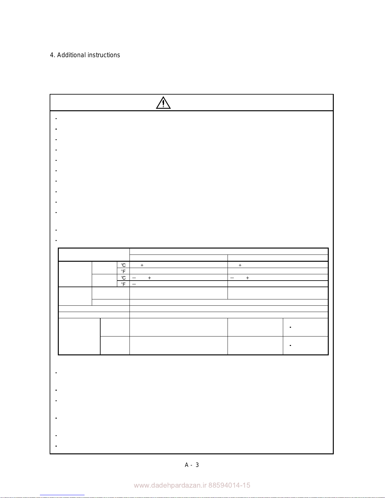
4. Additional instructions
The following instructions should also be fully noted. Incorrect handling may cause a fault, injury, electric
shock, etc.
(1) Transportation and installation
CAUTION
Transport the products correctly according to their masses.
Stacking in excess of the specified number of products is not allowed.
Do not carry the servo motor by the cables, shaft or encoder.
Do not hold the front cover to transport each unit. Each unit may drop.
Install the each unit in a load-bearing place in accordance with the Instruction Manual.
Do not climb or stand on servo equipment. Do not put heavy objects on equipment.
The controller and servo motor must be installed in the specified direction.
Leave specified clearances between the base unit and control enclosure walls or other equipment.
Do not install or operate the unit and servo motor which has been damaged or has any parts missing.
Provide adequate protection to prevent screws and other conductive matter, oil and other combustible
matter from entering each unit and servo motor.
Do not drop or strike each unit or servo motor. Isolate from all impact loads.
When you keep or use it, please fulfill the following environmental conditions.
Conditions
Environment
Each unit Servo motor
[ ] 0 to 55 (non-freezing) 0 to 40 (non-freezing)
During
operation
[
] 32 to 131 (non-freezing) 32 to 104 (non-freezing)
[ ] 20 to 65 (non-freezing) 15 to 70 (non-freezing)
Ambient
temperature
In storage
[
] 4 to 149 (non-freezing) 5 to 158 (non-freezing)
During
operation
90%RH or less (non-condensing) 80%RH or less (non-condensing)
Ambient
humidity
In storage 90%RH or less (non-condensing)
Ambience Indoors (no direct sunlight) Free from corrosive gas, flammable gas, oil mist, dust and dirt
Altitude Max. 1000m (3280 ft) above sea level
[m/s2] 5.9 or less
HC-KFS Series
HC-MFS Series
HC-UFS13 to 43
X Y : 49
(Note)
Vibration
[ft/s
2
] 19.4 or less
HC-KFS Series
HC-MFS Series
HC-UFS13 to 43
X Y : 161
Note. Except the servo motor with reduction gear.
Securely attach the servo motor to the machine. If attach insecurely, the servo motor may come off during
operation.
The servo motor with reduction gear must be installed in the specified direction to prevent oil leakage.
Take safety measures, e.g. provide covers, to prevent accidental access to the rotating parts of the servo
motor during operation.
Never hit the servo motor or shaft, especially when coupling the servo motor to the machine. The encoder
may become faulty.
Do not subject the servo motor shaft to more than the permissible load. Otherwise, the shaft may break.
When the equipment has been stored for an extended period of time, consult Mitsubishi.
www.dadehpardazan.ir 88594014-15
A - 4
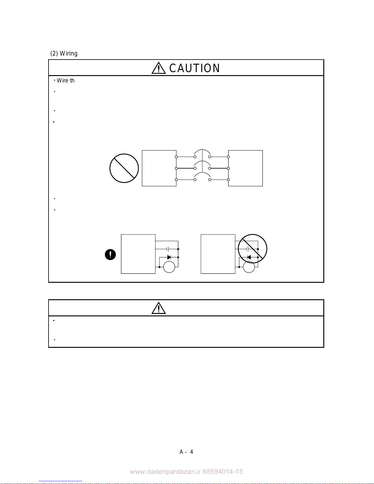
(2) Wiring
CAUTION
Wire the equipment correctly and securely. Otherwise, the servo motor may misoperate.
Do not install a power capacitor, surge absorber or radio noise filter (FR-BIF option) between the servo
motor and drive unit.
Connect the output terminals (U, V, W) correctly. Otherwise, the servo motor will operate improperly.
Connect the servo motor power terminal (U, V, W) to the servo motor power input terminal (U, V, W)
directly. Do not let a magnetic contactor, etc. intervene.
U
Drive unit
V
W
U
V
W
Servo Motor
Do not connect AC power directly to the servo motor. Otherwise, a fault may occur.
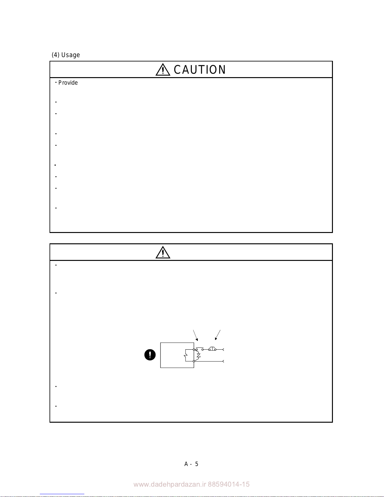
The surge absorbing diode installed on the DC output signal relay of the servo amplifier must be wired in
the specified direction. Otherwise, the forced stop and other protective circuits may not operate.
Interface unit
Control output
signal
VIN
SG
VIN
SG
RARA
Interface unit
Control output
signal
(3) Test run adjustment
CAUTION
Before operation, check the parameter settings. Improper settings may cause some machines to perform
unexpected operation.
The parameter settings must not be changed excessively. Operation will be insatiable.
www.dadehpardazan.ir 88594014-15
A - 5
(4) Usage
CAUTION
Provide a emergency stop circuit to ensure that operation can be stopped and power switched off
immediately.
Any person who is involved in disassembly and repair should be fully competent to do the work.
Before resetting an alarm, make sure that the run signal of the serv o amplifier is off to prevent an accident.
A sudden restart is made if an alarm is reset with the run signal on.
Do not modify the equipment.
Use a noise filter, etc. to minimize the influence of electromagnetic interference, which may be caused by
electronic equipment used near MELSERVO-J2M.
Burning or breaking each unit may cause a toxic gas. Do not burn or break each unit.
Use the drive unit with the specified servo motor.
The electromagnetic brake on the servo motor is designed to hold the motor shaft and should not be used
for ordinary braking.
For such reasons as service life and mechanical structure (e.g. where a ballscrew and the servo motor
are coupled via a timing belt), the electromagnetic brake may not hold the motor shaft. To ensure safety,
install a stopper on the machine side.
(5) Corrective actions
CAUTION
When it is assumed that a hazardous condition may take place at the occur due to a power failure or a
product fault, use a servo motor with electromagnetic brake or an external brake mechanism for the
purpose of prevention.
Configure the electromagnetic brake circuit so that it is activated not only by the interface unit signals bu t
also by a forced stop (EM1).
EM1RA
24VDC
Contacts must be open when
servo-off, when an alarm occurrence
and when an electromagnetic brake
interlock (MBR).
Electromagnetic brake
Servo motor
Circuit must be
opened during
forced stop (EM1).
When any alarm has occurred, eliminate its cause, ensure safety, and deactivate the alarm before
restarting operation.
When power is restored after an instantaneous power failure, keep away from the machine because the
machine may be restarted suddenly (design the machine so that it is secured against hazard if restarted).
www.dadehpardazan.ir 88594014-15
A - 6
(6) Maintenance, inspection and parts replacement
CAUTION
With age, the electrolytic capacitor of the drive unit will deteriorate . To prevent a secondary accident due
to a fault, it is recommended to replace the electrolytic capacitor ever y 10 years when used in general
environment.
Please consult our sales representative.
(7) General instruction
To illustrate details, the equipment in the diagrams of this Instruction Manual may have been drawn
without covers and safety guards. When the equipment is operated, the covers and safety guards must
be installed as specified. Operation must be performed in accordance with this Instruction Manual.
www.dadehpardazan.ir 88594014-15
A - 7
About processing of waste
When you discard servo amplifier, a battery (primary battery), and other option articles, please follow the law of
each country (area).
FOR MAXIMUM SAFETY
These products have been manufactured as a general-purpose part for general industries, and have not
been designed or manufactured to be incorporated in a device or system used in purposes related to
human life.
Before using the products for special purposes such as nuclear power, electric power, aerospace,
medicine, passenger movement vehicles or under water relays, contact Mitsubishi.
These products have been manufactured under strict quality control. However, when installing the product
where major accidents or losses could occur if the product fails, install appropriate backup or failsafe
functions in the system.
EEP-ROM life
The number of write times to the EEP-ROM, which stores parameter settings, etc., is limited to 100,000. If
the total number of the following operations exceeds 100,000, the servo amplifier and/or converter unit may
fail when the EEP-ROM reaches the end of its useful life.
Write to the EEP-ROM due to parameter setting changes
Precautions for Choosing the Products
Mitsubishi will not be held liable for damage caused by factors found not to be the cause of Mitsubishi;
machine damage or lost profits caused by faults in the Mitsubishi products; damage, secondary damage,
accident compensation caused by special factors unpredictable by Mitsubishi; damages to products other
than Mitsubishi products; and to other duties.
www.dadehpardazan.ir 88594014-15
A - 8
COMPLIANCE WITH EC DIRECTIVES
1. WHAT ARE EC DIRECTIVES?
The EC directives were issued to standardize the regulations of the EU countries and ensure smooth
distribution of safety-guaranteed products. In the EU countries, the machinery directive (effective in
January, 1995), EMC directive (effective in January, 1996) and low voltage directive (effective in January,
1997) of the EC directives require that products to be sold should meet their fundamental safety
requirements and carry the CE marks (CE marking). CE marking applies to machines and equipment
into which servo (MELSERVO-J2M is contained) have been installed.
(1) EMC directive
The EMC directive applies not to the servo units alone but to servo-incorporated machines and
equipment. This requires the EMC filters to be used with the servo-incorporated machines and
equipment to comply with the EMC directive. For specific EMC directive conforming methods, refer to
the EMC Installation Guidelines (IB(NA)67310).
(2) Low voltage directive
The low voltage directive applies also to MELSERVO-J2M. Hence, they are designed to comply with
the low voltage directive.
MELSERVO-J2M is certified by TUV, third-party assessment organization, to comply with the low
voltage directive.
(3) Machine directive
Not being machines, MELSERVO-J2M need not comply with this directive.
2. PRECAUTIONS FOR COMPLIANCE
(1) Unit and servo motors used
Use each units and servo motors which comply with the standard model.
Drive unit :MR-J2M-
DU
Interface unit :MR-J2M-P8B
Base unit :MR-J2M-BU
Servo motor :HC-KFS
HC-MFS
HC-UFS
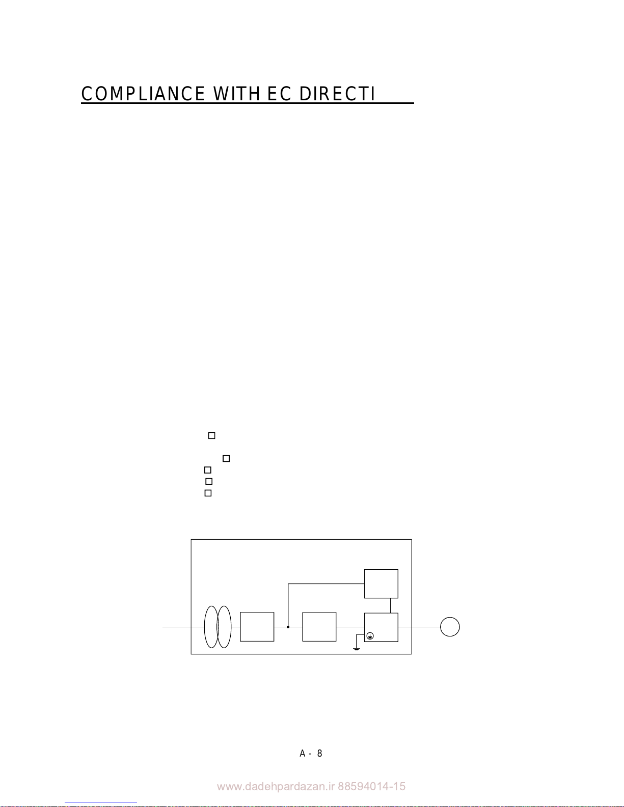
(2) Configuration
Reinforced
insulating
transformer
NFB
MC
M
No-fuse
breaker
Magnetic
contactor
Reinforced
insulating type
24VDC
power
supply
MELSERVOJ2M
Servo
motor
Control box

www.dadehpardazan.ir 88594014-15
A - 9
(3) Environment
Operate MELSERVO-J2M at or above the contamination level 2 set forth in IEC60664-1. For this
purpose, install MELSERVO-J2M in a control box which is protected against water, oil, carbon, dust,
dirt, etc. (IP54).
(4) Power supply
(a) Operate MELSERVO-J2M to meet the requirements of the overvoltage category II set forth in
IEC60664-1. For this purpose, a reinforced insulating transformer conforming to the IEC or EN
standard should be used in the power input section.
(b) When supplying interface power from external, use a 24VDC power supply which has been
insulation-reinforced in I/O.
(5) Grounding
(a) To prevent an electric shock, always connect the protective earth (PE) terminals (marked
) of the
base unit to the protective earth (PE) of the control box.
(b) Do not connect two ground cables to the same protective earth (PE) terminal. Always connect the
cables to the terminals one-to-one.
(c) If a leakage current breaker is used to prevent an electric shock, the protective earth (PE) terminals
of the base unit must be connected to the corresponding earth terminals.
(d) The protective earth (PE) of the servo motor is connected to the protective earth of the base unit via
the screw which fastens the drive unit to the base unit. When fixing the drive unit to the base unit,
therefore, tighten the accessory screw securely.
(6) Auxiliary equipment and options
(a) The no-fuse breaker and magnetic contactor used should be the EN or IEC standard-compliant
products of the models described in Section 12.2.2.
(b) The sizes of the cables described in Section 12.2.1 meet the following requirements. To meet the
other requirements, follow Table 5 and Appendix C in EN60204-1.
Ambient temperature: 40 (104) [ ( )]
Sheath: PVC (polyvinyl chloride)
Installed on wall surface or open table tray
(c) Use the EMC filter for noise reduction.
(7) Performing EMC tests
When EMC tests are run on a machine/device into which MELSERVO-J2M has been installed, it must
conform to the electromagnetic compatibility (immunity/emission) standards after it has satisfied the
operating environment/electrical equipment specifications.
For the other EMC directive guidelines on MELSERVO-J2M, refer to the EMC Installation
Guidelines(IB(NA)67310).
www.dadehpardazan.ir 88594014-15
A - 10
CONFORMANCE WITH UL/C-UL STANDARD
The MELSERVO-J2M complies with UL508C.
(1) Unit and servo motors used
Use the each units and servo motors which comply with the standard model.
Drive unit :MR-J2M-
DU
Interface unit :MR-J2M-P8B
Base unit :MR-J2M-BU
Servo motor :HC-KFS
HC-MFS
HC-UFS
(2) Installation
Install a fan of 100CFM (2.8m
3
/min)air flow 4 in (10.16 cm) above MELSERVO-J2M or provide cooling
of at least equivalent capability.
(3) Short circuit rating
MELSERVO-J2M conforms to the circuit whose peak current is limited to 5000A or less. Having been
subjected to the short-circuit tests of the UL in the alternating-current circuit, MELSERVO-J2M
conforms to the above circuit.
(4) Capacitor discharge time
The capacitor discharge time is as listed below. To ensure safety, do not touch the charging section for
15 minutes after power-off.
Base unit Discharge time [min]
MR-J2M-BU4 3
MR-J2M-BU6 4
MR-J2M-BU8 5
(5) Options and auxiliary equipment
Use UL/C-UL standard-compliant products.
(6) Attachment of a servo motor
For the flange size of the machine side where the servo motor is installed, refer to “CONFORMANCE
WITH UL/C-UL STANDARD” in the Servo Motor Instruction Manual.
(7) About wiring protection
For installation in United States, branch circuit protection must be provided, in accordance with the
National Electrical Code and any applicable local codes.
For installation in Canada, branch circuit protection must be provided, in accordance with the Canada
Electrical Code and any applicable provincial codes.
<<About the manuals>>
This Instruction Manual and the MELSERVO Servo Motor Instruction Manual are required if you use
MELSERVO-J2M for the first time. Always purchase them and use the MELSERVO-J2M safely.
Also read the manual of the servo system controller.
Relevant manuals
Manual name Manual No.
MELSERVO-J2M Series To Use the AC Servo Safely
(Packed with the MR-J2M-P8B, MR-J2M-
BU and MR-J2M-BU )
IB(NA)0300027
MELSERVO Servo Motor Instruction Manual SH(NA)3181
EMC Installation Guidelines IB(NA)67310
In this Instruction Manual, the drive unit, interface unit and base unit may be referred to as follows:
Drive unit : DRU
Interface unit : IFU
Base unit : BU
www.dadehpardazan.ir 88594014-15
1
CONTENTS
1. FUNCTIONS AND CONFIGURATION 1- 1 to 1-10
1.1 Overview................................................................................................................................................... 1- 1
1.2 Function block diagram ..........................................................................................................................1- 2
1.3 Unit standard specifications................................................................................................................... 1- 3
1.4 Function list ............................................................................................................................................. 1- 4
1.5 Model code definition .............................................................................................................................. 1- 5
1.6 Combination with servo motor............................................................................................................... 1- 6
1.7 Parts identification.................................................................................................................................. 1- 7
1.8 Servo system with auxiliary equipment................................................................................................ 1- 9
2. INSTALLATION AND START UP 2- 1 to 2-10
2.1 Environmental conditions....................................................................................................................... 2- 1
2.2 Installation direction and clearances .................................................................................................... 2- 2
2.3 Keep out foreign materials .....................................................................................................................2- 3
2.4 Cable stress .............................................................................................................................................. 2- 3
2.5 Mounting method ....................................................................................................................................2- 4
2.6 When switching power on for the first time.......................................................................................... 2- 6
2.7 Start up..................................................................................................................................................... 2- 7
2.8 Control axis selection .............................................................................................................................. 2- 9
3. SIGNALS AND WIRING 3- 1 to 3-28
3.1 Connection example of control signal system ....................................................................................... 3- 2
3.2 I/O signals of interface unit .................................................................................................................... 3- 4
3.2.1 Connectors and signal arrangements .............................................................................................3- 4
3.2.2 Signal explanations .......................................................................................................................... 3- 5
3.2.3 Interfaces ........................................................................................................................................... 3- 6
3.3 Signals and wiring for extension IO unit .............................................................................................. 3- 9
3.3.1 Connection example ......................................................................................................................... 3- 9
3.3.2 Connectors and signal configurations ........................................................................................... 3-11
3.3.3 Output signal explanations ............................................................................................................3-12
3.4 Signals and wiring for base unit ........................................................................................................... 3-14
3.4.1 Connection example of power line circuit...................................................................................... 3-14
3.4.2 Connectors and signal configurations ........................................................................................... 3-16
3.4.3 Terminals.......................................................................................................................................... 3-17
3.4.4 Power-on sequence........................................................................................................................... 3-18
3.5 Connection of drive unit and servo motor ............................................................................................3-19
3.5.1 Connection instructions ..................................................................................................................3-19
3.5.2 Connection diagram ........................................................................................................................ 3-19
3.5.3 I/O terminals .................................................................................................................................... 3-20
3.6 Alarm occurrence timing chart .............................................................................................................3-21
3.7 Servo motor with electromagnetic brake ............................................................................................. 3-22
3.8 Grounding................................................................................................................................................ 3-26
3.9 Instructions for the 3M connector.........................................................................................................3-27

www.dadehpardazan.ir 88594014-15
2
4. OPERATION AND DISPLAY 4- 1 to 4-10
4.1 Normal indication.................................................................................................................................... 4- 1
4.1.1 Display sequence............................................................................................................................... 4- 2
4.1.2 If alarm/warning occurs ................................................................................................................... 4- 3
4.2 Status display mode of interface unit.................................................................................................... 4- 4
4.2.1 Display flowchart.............................................................................................................................. 4- 4
4.2.2 Status display of interface unit .......................................................................................................4- 5
4.2.3 Diagnostic mode of interface unit ................................................................................................... 4- 6
4.2.4 Alarm mode of interface unit........................................................................................................... 4- 7
4.2.5 Interface unit parameter mode ....................................................................................................... 4- 8
4.2.6 Output signal (DO) forced output ................................................................................................... 4- 9
5. PARAMETERS 5- 1 to 5-26
5.1 Drive unit .................................................................................................................................................5- 1
5.1.1 Parameter write inhibit ...................................................................................................................5- 1
5.1.2 Lists....................................................................................................................................................5- 2
5.2 Interface unit ..........................................................................................................................................5-15
5.2.1 IFU parameter write inhibit........................................................................................................... 5-15
5.2.2 Lists...................................................................................................................................................5-15
5.2.3 Analog monitor................................................................................................................................. 5-21
5.2.4 Test operation mode ........................................................................................................................5-24
6. GENERAL GAIN ADJUSTMENT 6- 1 to 6-12
6.1 Different adjustment methods ...............................................................................................................6- 1
6.1.1 Adjustment on a MELSERVO-J2M................................................................................................ 6- 1
6.1.2 Adjustment using MR Configurator (servo configuration software) ...........................................6- 3
6.2 Auto tuning ..............................................................................................................................................6- 4
6.2.1 Auto tuning mode .............................................................................................................................6- 4
6.2.2 Auto tuning mode operation ............................................................................................................ 6- 5
6.2.3 Adjustment procedure by auto tuning............................................................................................ 6- 6
6.2.4 Response level setting in auto tuning mode .................................................................................. 6- 7
6.3 Manual mode 1 (simple manual adjustment)....................................................................................... 6- 8
6.3.1 Operation of manual mode 1 ........................................................................................................... 6- 8
6.3.2 Adjustment by manual mode 1 ....................................................................................................... 6- 8
6.4 Interpolation mode ................................................................................................................................. 6-11
7. SPECIAL ADJUSTMENT FUNCTIONS 7- 1 to 7-10
7.1 Function block diagram ..........................................................................................................................7- 1
7.2 Machine resonance suppression filter ................................................................................................... 7- 1
7.3 Adaptive vibration suppression control................................................................................................. 7- 3
7.4 Low-pass filter ......................................................................................................................................... 7- 4
7.5 Gain changing function........................................................................................................................... 7- 5
7.5.1 Applications ...................................................................................................................................... 7- 5
7.5.2 Function block diagram ................................................................................................................... 7- 5
7.5.3 Parameters........................................................................................................................................ 7- 6
7.5.4 Gain changing operation .................................................................................................................7- 8
8. INSPECTION 8- 1 to 8- 2
www.dadehpardazan.ir 88594014-15
3
9. TROUBLESHOOTING 9- 1 to 9-10
9.1 Alarms and warning list ......................................................................................................................... 9- 1
9.2 Remedies for alarms................................................................................................................................ 9- 3
9.3 Remedies for warnings........................................................................................................................... 9-10
10. OUTLINE DRAWINGS 10- 1 to 10- 10
10.1 MELSERVO-J2M configuration example......................................................................................... 10- 1
10.2 Unit outline drawings .........................................................................................................................10- 2
10.2.1 Base unit (MR-J2M-BU
)........................................................................................................... 10- 2
10.2.2 Interface unit (MR-J2M-P8B) .....................................................................................................10- 2
10.2.3 Drive unit (MR-J2M-
DU)......................................................................................................... 10- 3
10.2.4 Extension IO unit (MR-J2M-D01) ..............................................................................................10- 4
10.2.5 Battery unit (MR-J2M-BT).......................................................................................................... 10- 4
10.3 Connector .............................................................................................................................................10- 5
11. CHARACTERISTICS 11- 1 to 11- 6
11.1 Overload protection characteristics ...................................................................................................11- 1
11.2 Power supply equipment capacity and generated loss ....................................................................11- 2
11.3 Dynamic brake characteristics...........................................................................................................11- 4
11.4 Encoder cable flexing life .................................................................................................................... 11- 6
12. OPTIONS AND AUXILIARY EQUIPMENT 12- 1 to 12-36
12.1 Options.................................................................................................................................................. 12- 1
12.1.1 Regenerative brake options ......................................................................................................... 12- 1
12.1.2 Cables and connectors .................................................................................................................. 12- 8
12.1.3 Maintenance junction card (MR-J2CN3TM) ............................................................................12-21
12.1.4 MR Configurator (servo configurations software) .................................................................... 12-23
12.2 Auxiliary equipment ..........................................................................................................................12-25
12.2.1 Recommended wires .................................................................................................................... 12-25
12.2.2 No-fuse breakers, fuses, magnetic contactors........................................................................... 12-26
12.2.3 Power factor improving reactors ................................................................................................12-27
12.2.4 Relays............................................................................................................................................ 12-28
12.2.5 Surge absorbers ...........................................................................................................................12-28
12.2.6 Noise reduction techniques.........................................................................................................12-28
12.2.7 Leakage current breaker ............................................................................................................ 12-34
12.2.8 EMC filter..................................................................................................................................... 12-35
13. ABSOLUTE POSITION DETECTION SYSTEM 13- 1 to 13- 4
13.1 Features................................................................................................................................................ 13- 1
13.2 Specifications .......................................................................................................................................13- 2
13.3 Confirmation of absolute position detection data............................................................................. 13- 3
APPENDIX App- 1 to App- 2
App 1. Status indication block diagram ................................................................................................. App- 1
www.dadehpardazan.ir 88594014-15
4
Optional Servo Motor Instruction Manual CONTENTS
The rough table of contents of the optional MELSERVO Servo Motor Instruction Manual is introduced
here for your reference. Note that the contents of the Servo Motor Instruction Manual are not included in
this Instruction Manual.
1. INTRODUCTION
2. INSTALLATION
3. CONNECTORS USED FOR SERVO MOTOR WIRING
4. INSPECTION
5. SPECIFICATIONS
6. CHARACTERISTICS
7. OUTLINE DIMENSION DRAWINGS
8. CALCULATION METHODS FOR DESIGNING
www.dadehpardazan.ir 88594014-15
1 - 1
1. FUNCTIONS AND CONFIGURATION
1. FUNCTIONS AND CONFIGURATION
1.1 Overview
The Mitsubishi general-purpose AC servo MELSERVO-J2M series is an AC servo which has realized
wiring-saving, energy-saving and space-saving in addition to the high performance and high functions of
the MELSERVO-J2-Super series. Connected with a servo system controller or like by a serial bus
(SSCNET), the equipment reads position data directly to perform operation. Data from a command unit
are used to control the speeds and directions of servo motors and execute precision positioning.
The MELSERVO-J2M series consists of an interface unit (abbreviated to the IFU) to be connected with a
servo system controller, drive units (abbreviated to the DRU) for driving and controlling servo motors,
and a base unit (abbreviated to the BU) where these units are installed.
A torque limit is applied to the drive unit by the clamp circuit to protect the main circuit power
transistors from overcurrent caused by abrupt acceleration/deceleration or overload. In addition, the
torque limit value can be changed as desired using the parameter.
The interface unit has an RS-232C serial communication function to allow the parameter setting, test
operation, status indication monitoring, gain adjustment and others of all units to be performed using a
personal computer or like where the MR Configurator (servo configuration software) is installed. By
choosing the axis number of the drive unit using the MR Configurator (servo configuration software), you
can select the unit to communicate with, without changing the cabling.
The real-time auto tuning function automatically adjusts the servo gains according to a machine.
The MELSERVO-J2M series supports as standard the absolute position encoders which have 131072
pulses/rev resolution, ensuring control as accurate as that of the MELSERVO-J2-Super series. Simply
adding the optional battery unit configures an absolute position detection system. Hence, merely setting a
home position once makes it unnecessary to perform a home position return at power-on, alarm
occurrence or like.
The MELSERVO-J2M series has a control circuit power supply in the interface unit and main circuit
converter and regenerative functions in the base unit to batch-wire the main circuit power input,
regenerative brake connection and control circuit power input, achieving wiring-saving.
In the MELSERVO-J2M series, main circuit converter sharing has improved the capacitor regeneration
capability dramatically. Except for the operation pattern where all axes slow down simultaneously, the
capacitor can be used for regeneration. You can save the energy which used to be consumed by the
regenerative brake resistor.
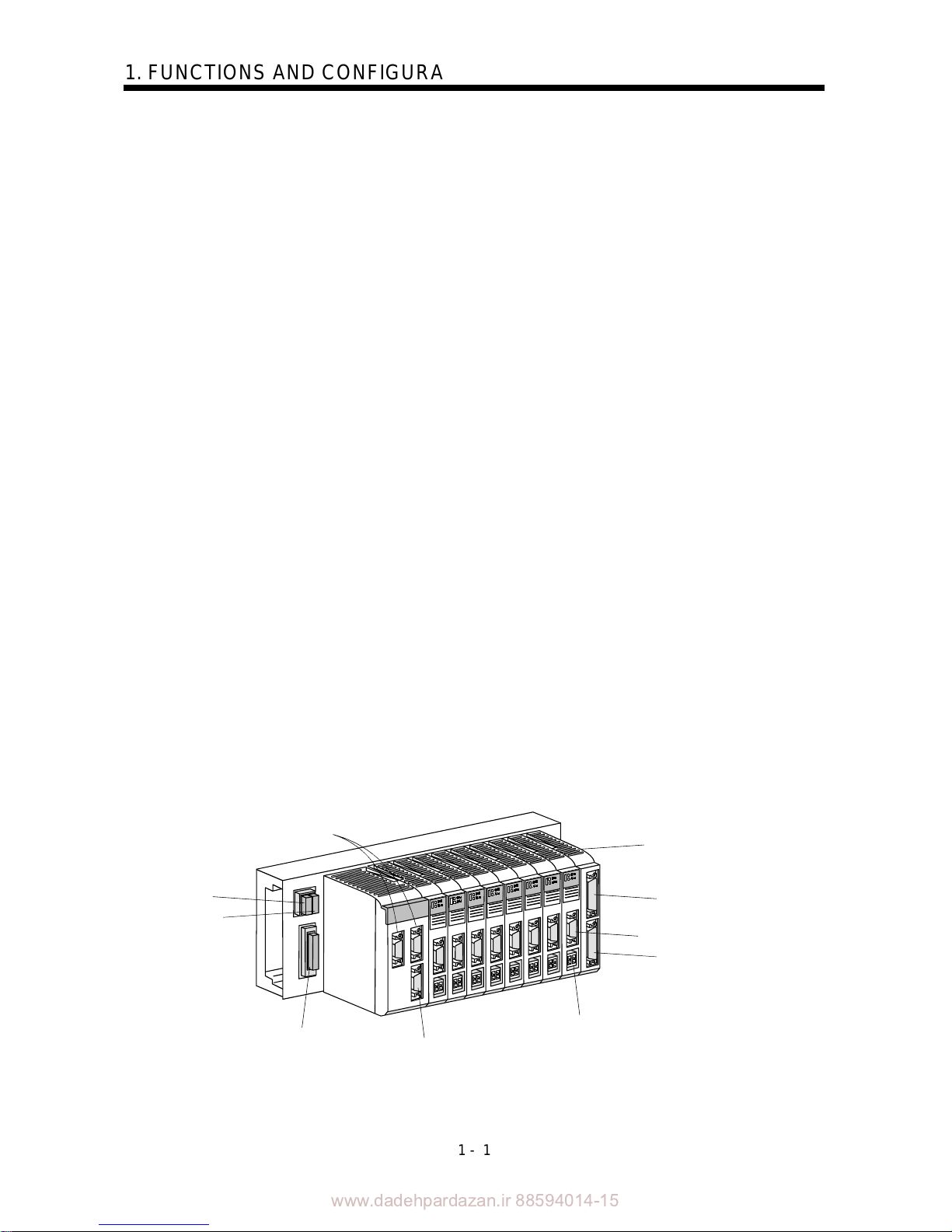
Bus cable connections
Regenerative
brake option
Control circuit
power input
Main circuit power input
Personal computer connection
Analog monitor
Forced stop input
Electromagnetic brake interlock output
Servo motor power cable
Encoder pulse output
extension DIO (Axes 5 to 8
)
Encoder cable
Encoder pulse output
extension DIO (Axes 1 to 4)
Extension IO unit
MR-J2M-D01
www.dadehpardazan.ir 88594014-15
1 - 2
1. FUNCTIONS AND CONFIGURATION
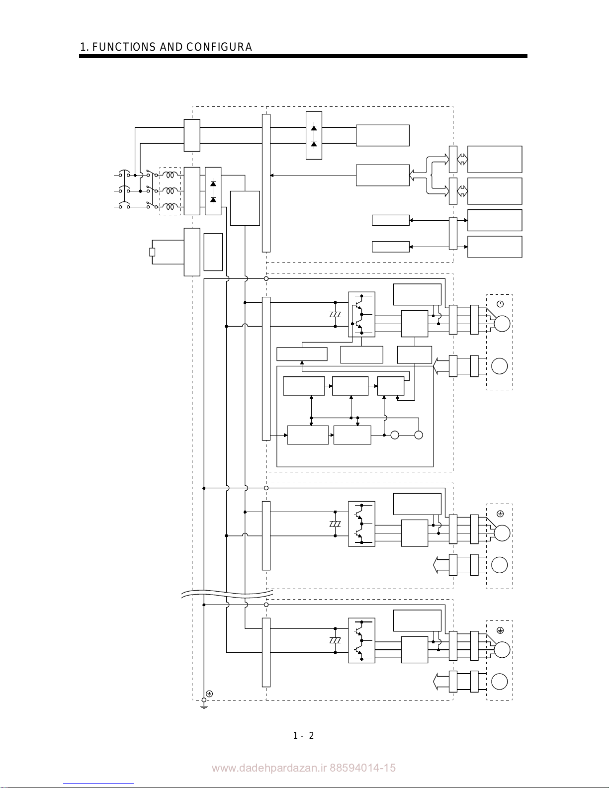
1.2 Function block diagram
W
RS-232C
D/A
NFB MC
U
V
W
M
L11
L
21
L1
L2
L
3
CNP3
P
N
C
CNP1A
U
V
M
CN1ACN1BCN3CNP2CN2CNP2CN2
W
U
V
M
CNP2CN2
CON3A-3H CON3A-3H CON3A-3H
FR-BAL
Power
supply
3-phase
200 to
230VAC
(Note)
1-phase
200 to
230VAC
Base unit Interface unit
I/F Control
I/F Control
Controller or
Servo amplifier
Servo amplifier
or termination
connector
Personal
computer
Analog monitor
(3 channels)
Regenerative brake option
Regener-
ative TR
Drive unit
Dynamic
brake
Servo motor
Inrush
current
suppression
circuit
Current
detector
Overcurrent
protection
Current
detection
Base amplifier
Actual position
control
Actual speed
control
Current
control
Model position
control
Model speed
control
Virtual
encoder
Virtual
servo
motor
Drive unit
Encoder
Drive unit
Dynamic
brake
Servo motor
Encoder
Current
detection
Dynamic
brake
Current
detection
Servo motor
Encoder
Position
command
input
Model
position
Model
speed
Model
torque
Position command
Note. For 1-phase 200 to 230VAC, connect the power supply to L
1
, L2 and leave L3 open.
CNP1B
(Earth)
(Earth)
(Earth)
www.dadehpardazan.ir 88594014-15
1 - 3
1. FUNCTIONS AND CONFIGURATION
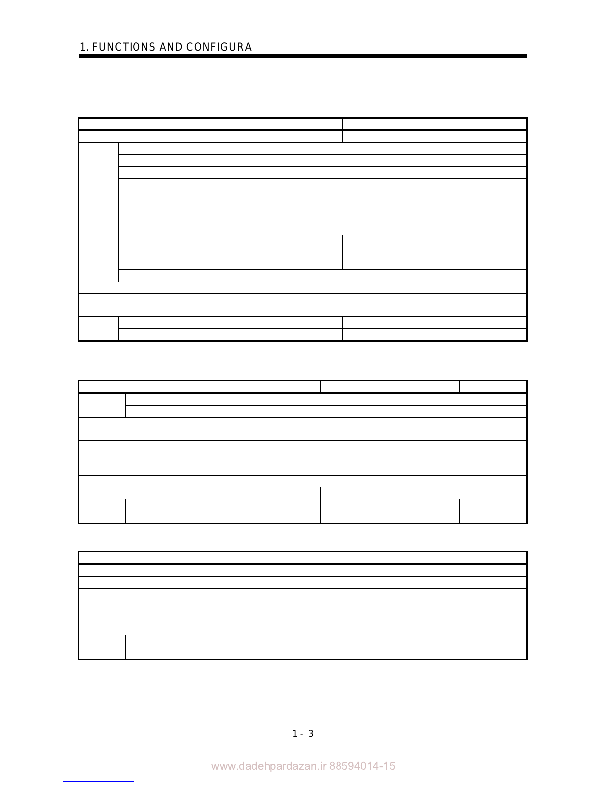
1.3 Unit standard specifications
(1) Base unit
Model MR-J2M-BU4 MR-J2M-BU6 MR-J2M-BU8
Number of slots 4 6 8
Voltage/frequency 3-phase 200 to 230VAC or 1-phase 200 to 230VAC, 50/60Hz
Permissible voltage fluctuation 1-phase 170 to 253VAC
Permissible frequency fluctuation Within 5%
(Note)
Control
circuit
power
supply
Inrush current 20A (5ms)
Voltage/frequency 3-phase 200 to 230VAC or 1-phase 200 to 230VAC, 50/60Hz
Permissible voltage fluctuation 3-phase 170 to 253VAC or 1-phase 170 to 253VAC, 50/60Hz
Permissible frequency fluctuation Within 5%
Maximum servo motor connection
capacity [W]
1600 2400 3200
Continuous capacity [W] 1280 1920 2560
Main
circuit
power
supply
Inrush current 62.5A (15ms)
Function Converter function, regenerative control, rushing into current control function
Protective functions
Regenerative overvoltage shut-off, regenerative fault protection,
undervoltage /instantaneous power failure protection
[kg] 1.1 1.3 1.5
Mass
[lb] 2.4 2.9 3.3
Note. The control circuit power supply is recorded to the interface unit.
(2) Drive unit
Model MR-J2M-10DU MR-J2M-20DU MR-J2M-40DU MR-J2M-70DU
Voltage/frequency 270 to 311VDC
Power
supply
Permissible voltage fluctuation 230 to 342VDC
Control system Sine-wave PWM control, current control system
Dynamic brake Built-in
Protective functions
Overcurrent shut-off, functions overload shut-off (electronic thermal relay),
servo motor overheat protection, encoder fault protection, overspeed
protection, excessive error protection
Structure Open (IP00)
Cooling method Self-cooled Force-cooling (With built-in fan unit)
[kg] 0.4 0.4 0.4 0.7
Mass
[lb] 0.89 0.89 0.89 1.54
(3) Interface unit
Model MR-J2M-P8B
Control circuit power supply Power supply circuit for each unit(8 slots or less)
Interface SSCNET interface 1channel RS-232C interface 1channel
DIO
Forced stop input(1 point), Electromagnetic brake sequence output
(1 point)
AIO Analog monitor 3channel
Structure Open (IP00)
[kg] 0.5
Mass
[lb] 1.10
www.dadehpardazan.ir 88594014-15
1 - 4
1. FUNCTIONS AND CONFIGURATION
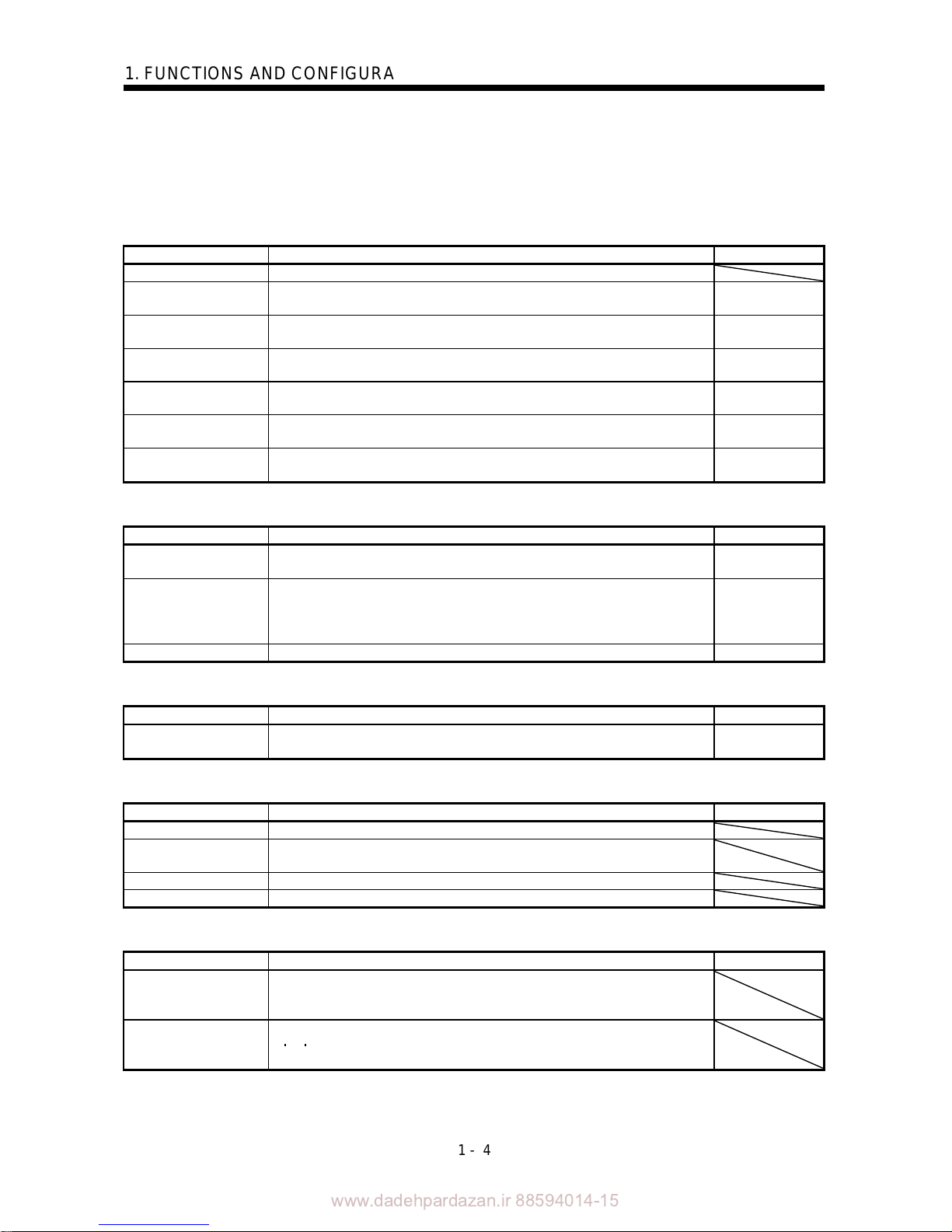
1.4 Function list
The following table lists the functions of this servo. For details of the functions, refer to the Reference
field.
(1) Drive unit (Abbreviation DRU)
Function Description Reference
High-resolution encoder High-resolution encoder of 131072 pulses/rev is used as a servo motor encoder.
Auto tuning
Automatically adjusts the gain to optimum value if load applied to the servo motor
shaft varies.
Chapter 6
Adaptive vibration
suppression control
MELSERVO-J2M detects mechanical resonance and sets filter characteristics
automatically to suppress mechanical vibration.
Section 7.3
Low-pass filter
Suppresses high-frequency resonance which occurs as servo system response is
increased.
Section 7.4
Slight vibration
suppression control
Suppresses vibration of 1 pulse produced at a servo motor stop.
DRU Parameter
No.24
Forced stop signal
automatic ON
Forced stop (EM1) can be automatically switched on internally to invalidate it.
DRU Parameter
No.23
Torque limit Servo motor torque can be limited to any value.
DRU Parameters
No.10, No.11
(2) Interface unit (Abbreviation IFU)
Function Description Reference
Forced stop signal input Disconnect forced stop (EM1) to bring the servo motor to a forced stop state, in
which the servo is switched off and the dynamic brake is operated.
Section 3.2.2
Electromagnetic brake
output
In the servo-off or alarm status, this signal is disconnected.
When an alarm occurs, they are disconnected, independently of the base circuit
status.
It is possible to use it to excite an electromagnetic brake.
Section 3.2.2
Analog monitor Servo status is output in terms of voltage in real time. Section 5.2.3
(3) Base unit (Abbreviation BU)
Function Description Reference
Regenerative brake option
Used when the built-in regenerative brake resistor of the unit does not have
sufficient regenerative capability for the regenerative power generated.
Section 12.1.1
(4) MR Configurator (servo configuration software)
Function Description Reference
Machine analyzer function Analyzes the frequency characteristic of the mechanical system.
Machine simulation
Can simulate machine motions on a personal computer screen on the basis of the
machine analyzer results.
Gain search function Can simulate machine motions on the basis of the machine analyzer results.
Test operation mode JOG operation and positioning operation are possible.
(5) Option unit
Function Description Reference
Absolute position
detection system
Merely setting a home position once makes home position return unnecessary at
every power-on.
Battery unit MR-J2M-BT is necessary.
Encoder pulse output
The encoder feedback is output from enhancing IO unit MR-J2M-D01 by the
A
B Z phase pulse. The number of pulses output by the parameter can be
changed.
www.dadehpardazan.ir 88594014-15
1 - 5
1. FUNCTIONS AND CONFIGURATION
1.5 Model code definition
(1) Drive unit
(a) Rating plate
400W
DC270V-311V
170V 0-360Hz 2.3A
N9Z95046
MR-J2M-40DU
SON
ALM
MODEL
POWER
INPUT
OUTPUT
SERIAL
TC300A***G51
MITSUBISHI ELECTRIC
Model
Capacity
Applicable power supply
Rated output current
Serial number
Rating plate
Rating plate
(b) Model code
100
200
400
Rated output
10
20
40
MR-J2M- DU
Symbol Capacity of applied servo motor
70
750
(2) Interface unit
(a) Rating plate
Model
Input capacity
Applicable
power supply
Output voltage / current
Serial number
Rating
plate
MITSUBISHI
MADE IN JAPAN
MODEL
MITSUBISHI ELECTRIC CORPORATION
AC SERVO
PASSED
POWER :
OUTPUT :
SERIAL :A5*******
TC3**AAAAG52
MR-J2M-P8B
75W
2PH AC200-230V 50Hz
2PH AC200-230V 60Hz
DC5/12/20 4.6A/1.2/0.7A
AC INPUT:
(b) Model code
MR-J2M-P8B
SSCNET compatible
www.dadehpardazan.ir 88594014-15
1 - 6
1. FUNCTIONS AND CONFIGURATION
(3) Base unit
(a) Rating plate
MITSUBISHI
MADE IN JAPAN
MR-J2M-BU4
3PH 200-230
INPUT :
SERIAL:
14A 50/60Hz
N87B95046
BC336U246
MODEL
MITSUBISHI ELECTRIC
PASSED
Model
Applicable power
supply
Serial number
Rating plate
(b) Model code
61920
4
8
1600
2400
3200
1280
2560
MR-J2M-BU
Symbol
4
6
8
Number of
slots
Maximum servo motor
connection capacity [W]
Continuous capacity [W]
1.6 Combination with servo motor
The following table lists combinations of drive units and servo motors. The same combinations apply to
the models with electromagnetic brakes and the models with reduction gears.
Servo motor
Drive unit
HC-KFS
HC-MFS HC-UFS
MR-J2M-10DU 053 13 053 13 13
MR-J2M-20DU 23 23 23
MR-J2M-40DU 43 43 43
MR-J2M-70DU 73 73 73
www.dadehpardazan.ir 88594014-15
1 - 7
1. FUNCTIONS AND CONFIGURATION
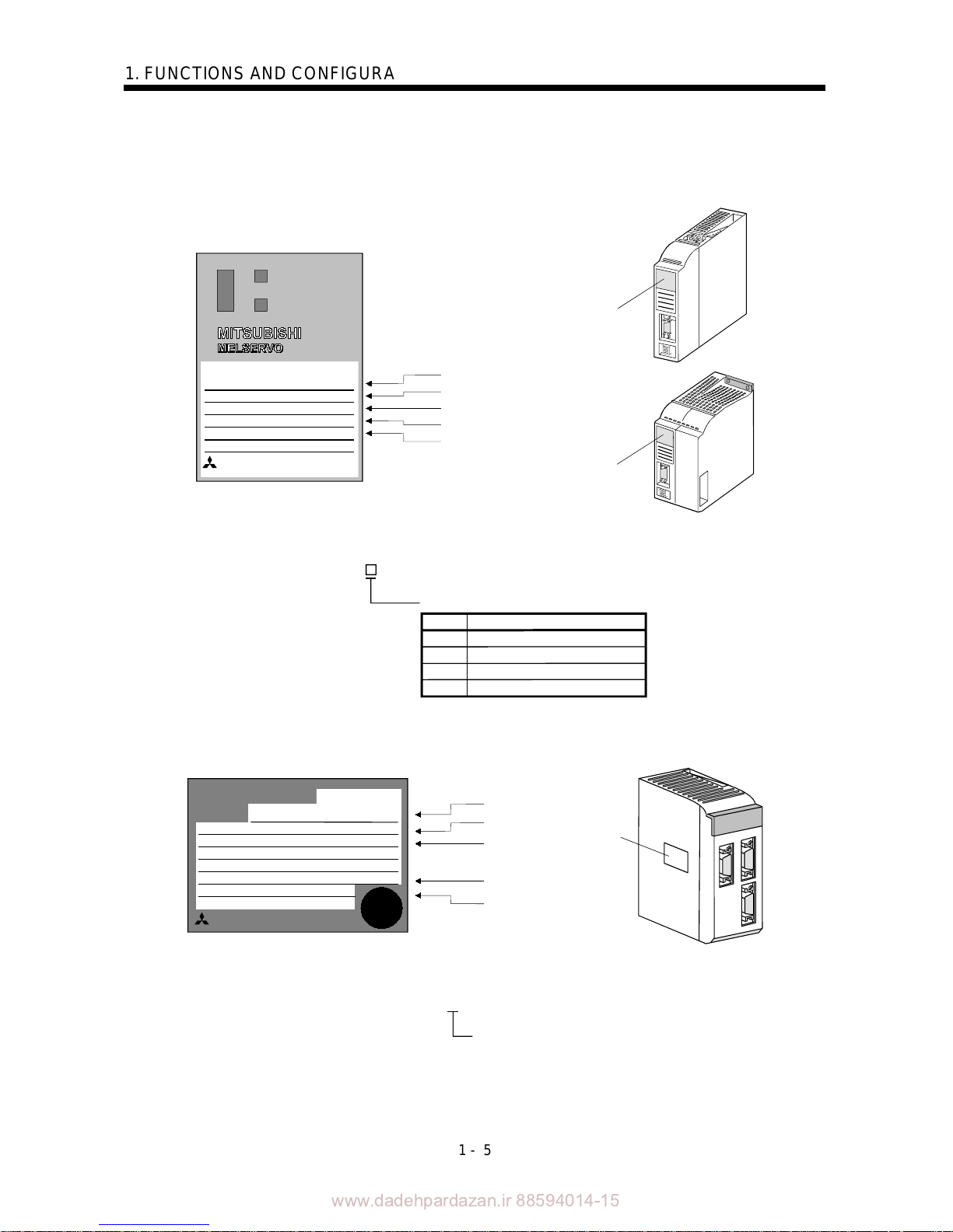
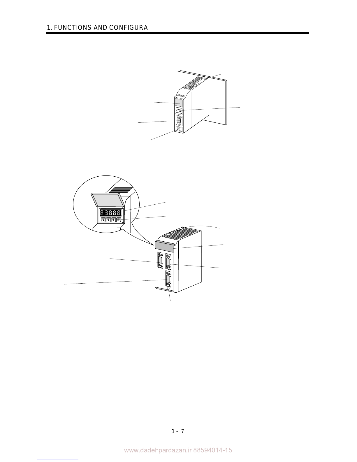
1.7 Parts identification
(1) Drive unit
Status indicator LED
Indicates the status of the drive unit.
Blinking green: Servo off status
Steady green: Servo on status
Blinking red: Warning status
Steady red: Alarm status
CN2
Encoder connector
Connect the servo
motor encoder
CNP2
Servo motor connector
For connection of servo
motor power line cable
Mounting screw
Rating plate
(2) Interface unit
Display
Indicates operating status or alarm.
CN1A
Bus cable connector
For connection of servo system controller or
preceding-axis servo amplifier.
CN3
For connection of personal computer (RS-232C).
Outputs analog monitor.
Pushbutton switches
Used to change status indication or set IFU parameters.
Mounting screw
Display/setting cover
CN1B
Bus cable connector
For connection of subsequent-axis servo
amplifier or MR-A-TM terminati on connector.
Charge lamp
Lit when main circuit capacitor carries electrical charge.
When this lamp is on, do not remove/reinstall any unit
from/to base unit and do not unplug/plug cable and
connector from/into any unit.
www.dadehpardazan.ir 88594014-15
1 - 8
1. FUNCTIONS AND CONFIGURATION
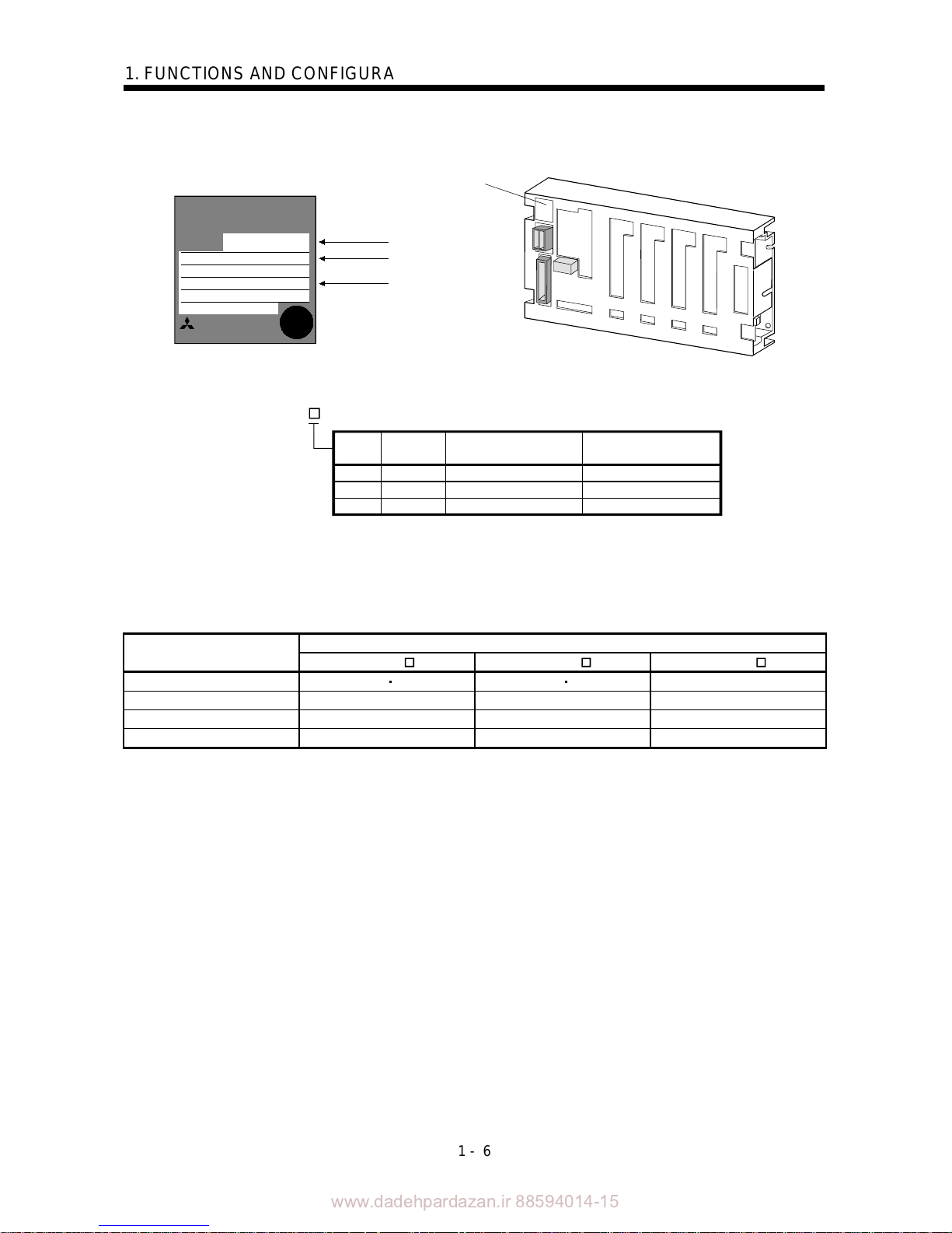
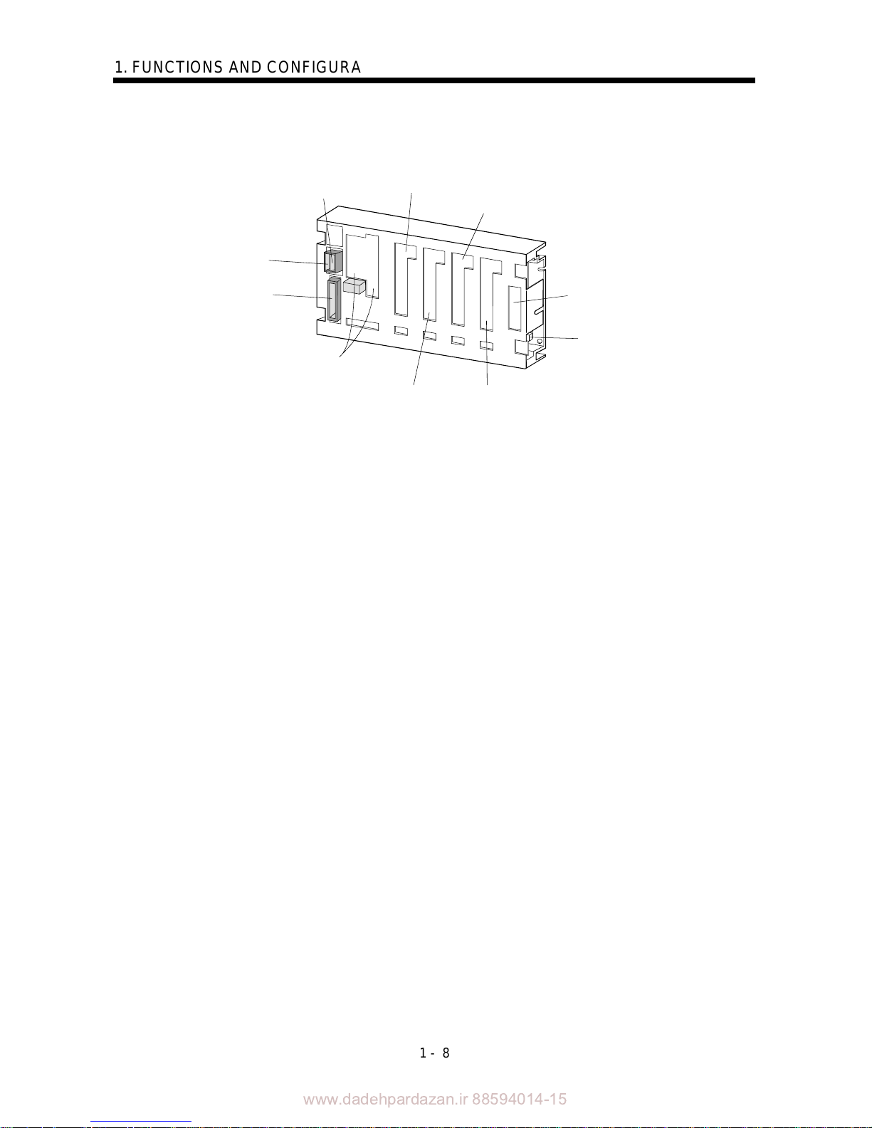
(3) Base unit
The following shows the MR-J2M-BU4.
CNP1B
Control circuit power input connector
CNP1A
Regenerative brake
option connector
CNP3
Main circuit power
input connector
CON1,CON2
Interface unit connectors
CON3B
Second slot connector
CON3D
Fourth slot connector
CON4
Option slot connector
CON5
Battery unit connecto
r
CON3C
Third slot connector
CON3A
First slot connector
www.dadehpardazan.ir 88594014-15
1 - 9
1. FUNCTIONS AND CONFIGURATION
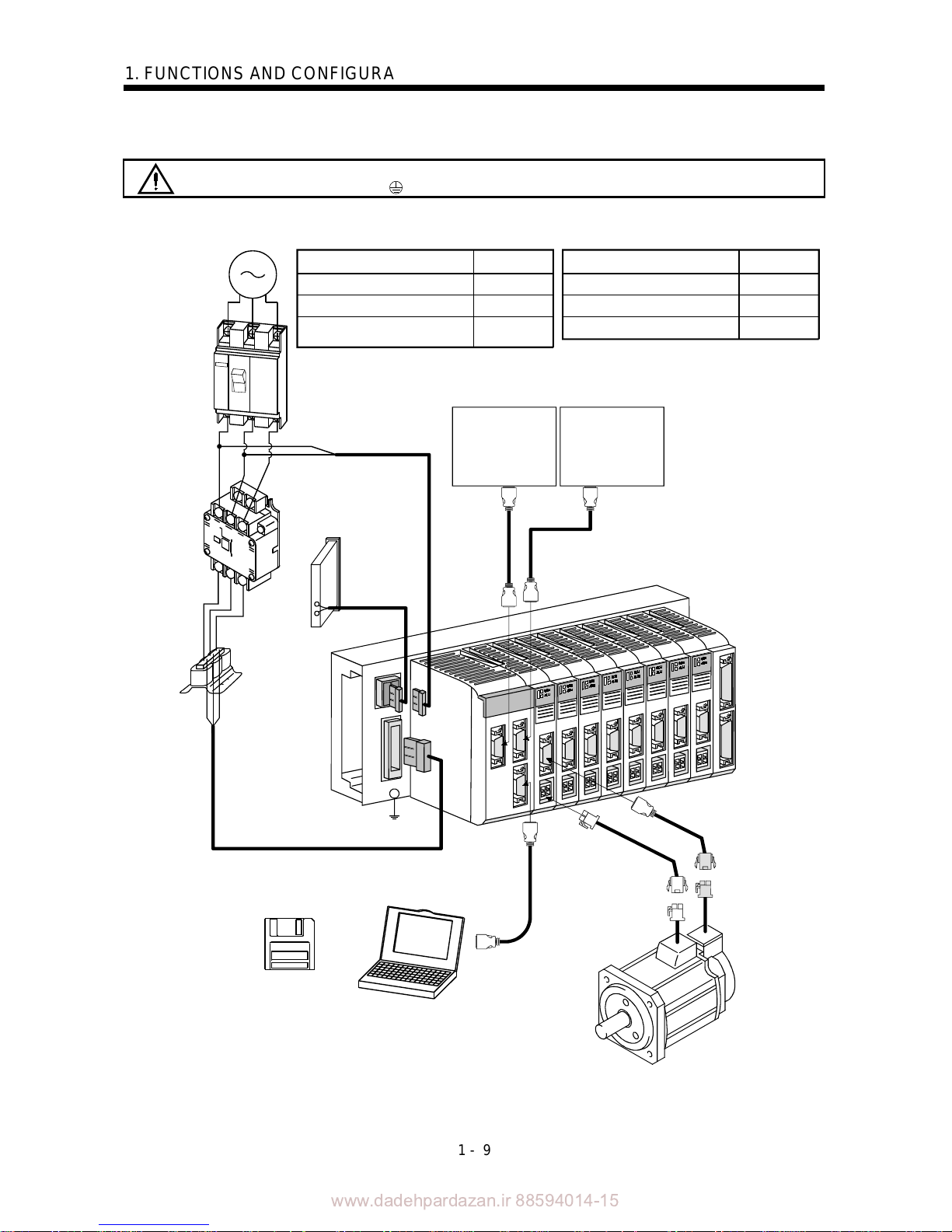
1.8 Servo system with auxiliary equipment
WARNING
To prevent an electric shock, always connect the protective earth (PE) terminal
(terminal marked
) of the base unit to the protective earth (PE) of the control box.
L
21
C
P
L2
L
1
L3
L
11
Options and auxiliary equipment
No-fuse breaker
Magnetic contactor
MR Configurator
(servo configuration software)
Regenerative brake option
Reference
Section 12.2.2
Section 12.2.2
Section 12.1.4
Section 12.1.1
Options and auxiliary equipment
Cables
Section 12.2.1
Power factor improving reactor
Section 12.2.3
3-phase 200V to 230VAC
(Note) 1-phase 200V to 230VAC
power supply
No-fuse breake
r
(NFB) or fuse
Magnetic
contactor
(MC)
Power
factor
improving
reactor
(FR-BAL)
MR Configurator
(servo configuration
software)
Personal
computer
Power supply lead
Encoder cable
To CNP1A
To CN1A To CN1B
Servo system
controller
or
Preceding axis
servo amplifier
Subsequent axis
servo amplifier
or
Termination
connector
Regenerative brake
option
To CNP1B
To CNP3
Reference
Control circuit
power supply
Main circuit
power supply
To CN3
Note. For 1-phase 200 to 230VAC, connect the power supply to L
1
, L2 and leave L3 open.

www.dadehpardazan.ir 88594014-15
1 - 10
1. FUNCTIONS AND CONFIGURATION
MEMO
www.dadehpardazan.ir 88594014-15
2 - 1
2. INSTALLATION AND START UP
2. INSTALLATION AND START UP
CAUTION
Stacking in excess of the limited number of products is not allowed.
Install the equipment to incombustibles. Installing them directly or close to
combustibles will led to a fire.
Install the equipment in a load-bearing place in accordance with this Instruction
Manual.
Do not get on or put heavy load on the equipment to prevent injury.
Use the equipment within the specified environmental condition range.
Provide an adequate protection to prevent screws, metallic detritus and other
conductive matter or oil and other combustible matter from entering each unit.
Do not block the intake/exhaust ports of each unit. Otherwise, a fault may occur.
Do not subject each unit to drop impact or shock loads as they are precision
equipment.
Do not install or operate a faulty unit.
When the product has been stored for an extended period of time, consult
Mitsubishi.
When treating the servo amplifier, be careful about the edged parts such as the
corners of the servo amplifier.
2.1 Environmental conditions
The following environmental conditions are common to the drive unit, interface unit and base unit.
Environment Conditions
[ ]0 to 55 (non-freezing)
During
operation
[
] 32 to 131 (non-freezing)
[ ] 20 to 65 (non-freezing)
Ambient
temperature
In storage
[
] 4 to 149 (non-freezing)
During operation
Ambient
humidity
In storage
90%RH or less (non-condensing)
Ambience
Indoors (no direct sunlight)
Free from corrosive gas, flammable gas, oil mist, dust and dirt
Altitude Max. 1000m (3280 ft) above sea level
[m/s2] 5.9 [m/s2] or less
Vibration
[ft/s
2
] 19.4 [ft/s2] or less
www.dadehpardazan.ir 88594014-15
2 - 2
2. INSTALLATION AND START UP
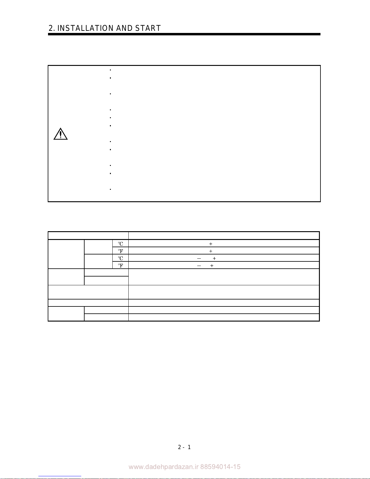
2.2 Installation direction and clearances
CAUTION
The equipment must be installed in the specified direction. Otherwise, a fault may
occur.
Leave specified clearances between each unit and control box inside walls or other
equipment.
(1) Installation of one MELSERVO-J2M
40mm(1.57inch) or more
40mm(1.57inch) or more
40mm(1.57inch) or more
40mm(1.57inch) or more
(2) Installation of two or more MELSERVO-J2M
When installing two units vertically, heat generated by the lower unit influences the ambient
temperature of the upper unit. Suppress temperature rises in the control box so that the temperature
between the upper and lower units satisfies the environmental conditions. Also provide adequate
clearances between the units or install a fan.
40mm(1.57inch) or more
Leave 100mm(3.94inch) or more
clearance or install fan for forced air cooling.
40mm(1.57inch) or more
40mm(1.57inch) or more
40mm(1.57inch) or more

www.dadehpardazan.ir 88594014-15
2 - 3
2. INSTALLATION AND START UP
(3) Others
When using heat generating equipment such as the regenerative brake option, install them with full
consideration of heat generation so that MELSERVO-J2M is not affected.
Install MELSERVO-J2M on a perpendicular wall in the correct vertical direction.
2.3 Keep out foreign materials
(1) When installing the unit in a control box, prevent drill chips and wire fragments from entering each
unit.
(2) Prevent oil, water, metallic dust, etc. from entering each unit through openings in the control box or a
fan installed on the ceiling.
(3) When installing the control box in a place where there are much toxic gas, dirt and dust, conduct an
air purge (force clean air into the control box from outside to make the internal pressure higher than
the external pressure) to prevent such materials from entering the control box.
2.4 Cable stress
(1) The way of clamping the cable must be fully examined so that flexing stress and cable's own mass
stress are not applied to the cable connection.
(2) For use in any application where the servo motor moves, fix the cables (encoder, power supply, brake)
supplied with the servo motor, and flex the optional encoder cable or the power supply and brake
wiring cables. Use the optional encoder cable within the flexing life range. Use the power supply and
brake wiring cables within the flexing life of the cables.
(3) Avoid any probability that the cable sheath might be cut by sharp chips, rubbed by a machine corner
or stamped by workers or vehicles.
(4) For installation on a machine where the servo motor will move, the flexing radius should be made as
large as possible. Refer to section 11.4 for the flexing life.
www.dadehpardazan.ir 88594014-15
2 - 4
2. INSTALLATION AND START UP
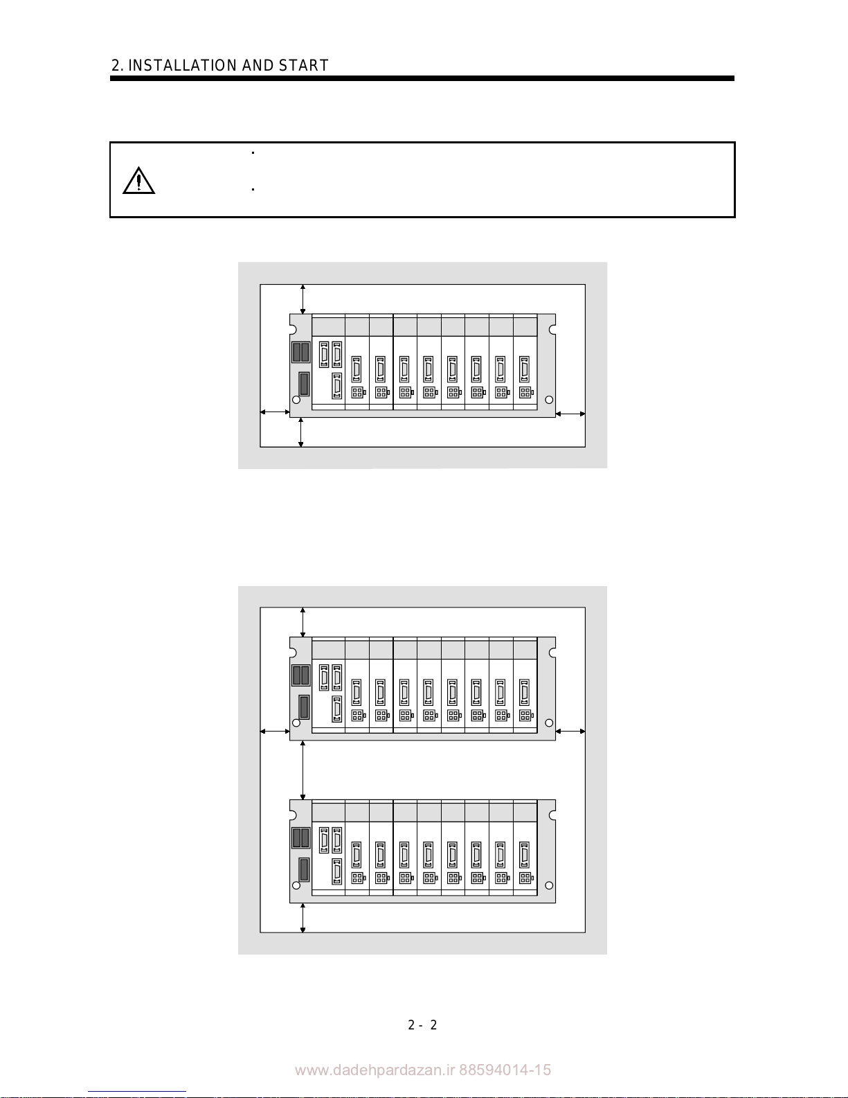
2.5 Mounting method
(1) Base unit
As shown below, mount the base unit on the wall of a control box or like with M5 screws.
Wall
(2) Interface unit/drive unit (MR-J2M-40DU or less)
The following example gives installation of the drive unit to the base unit. The same also applies to the
interface unit.
Sectional view
Drive unit
Base unit
Wall
Catch
Positioning hole
1)
1) Hook the catch of the drive unit in the positioning hole of the base unit.
Sectional view
2)
Drive unit
Base unit
Wall
2) Using the catch hooked in the positioning hole as a support, push the drive unit in.

www.dadehpardazan.ir 88594014-15
2 - 5
2. INSTALLATION AND START UP
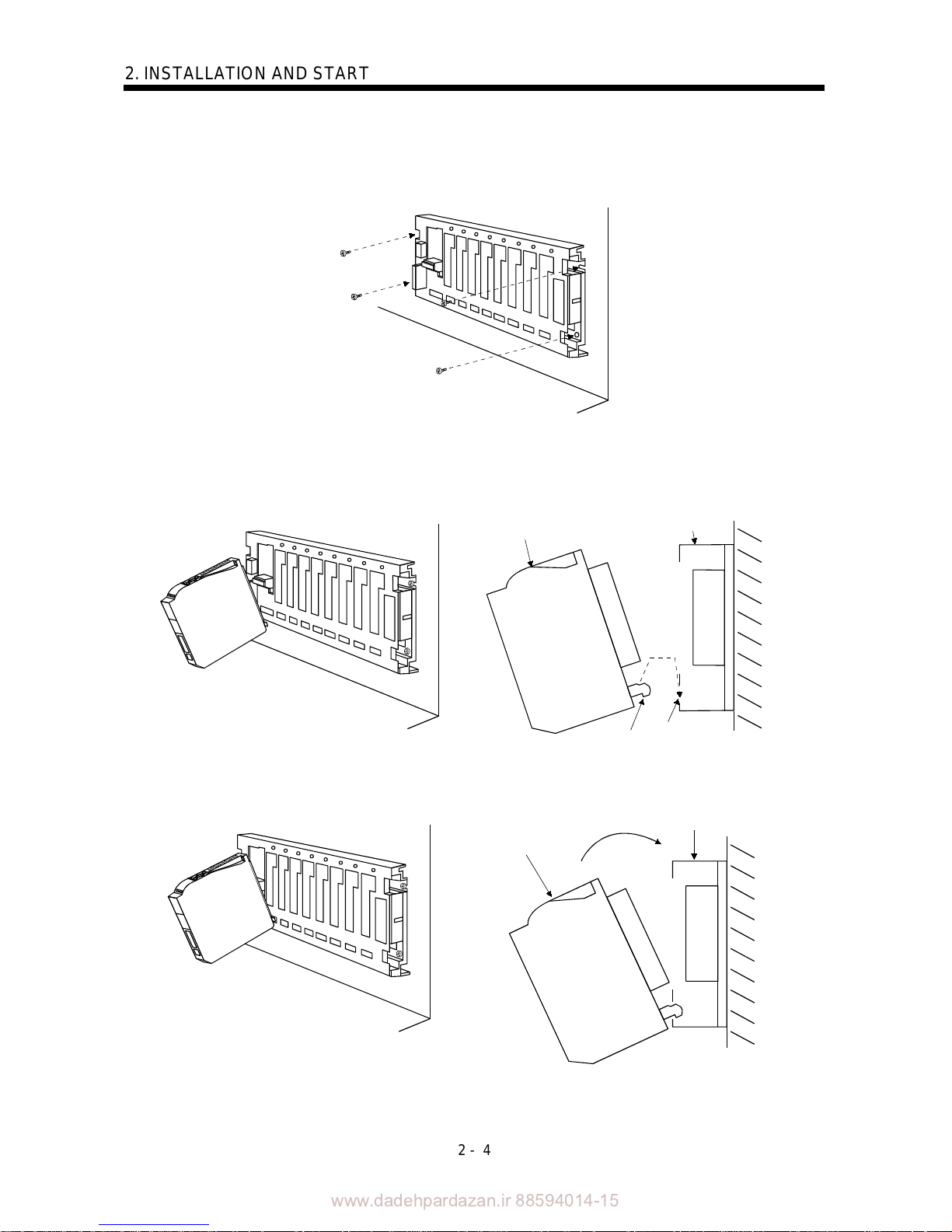
3)
3)
Sectional view
Wall
3) Tighten the M4 screw supplied for the base unit to fasten the drive unit to the base unit.
POINT
Securely tighten the drive unit fixing screw.
Sectional view
Wall
(3) Drive unit (MR-J2M-70DU)
When using the MR-J2M-70DU, install it on two slots of the base unit. The slot number of this drive
unit is that of the left hand side slot of the two occupied slots, when they are viewed from the front of
the base unit.

www.dadehpardazan.ir 88594014-15
2 - 6
2. INSTALLATION AND START UP
2.6 When switching power on for the first time
Before starting operation, check the following:
(1) Wiring
(a) Check that the control circuit power cable, main circuit power cable and servo motor power cable
are fabricated properly.
(b) Check that the control circuit power cable is connected to the CNP1B connector and the main
circuit power cable is connected to the CNP3 connector.
(c) Check that the servo motor power cable is connected to the drive unit CNP2 connector.
(d) The earth terminal of the servo motor is connected to the PE terminal of the drive unit. Also check
that the drive unit is screwed to the base unit securely.
(e) When using the regenerative brake option, check that the cable using twisted wires is fabricated
properly and it is connected to the CNP1A connector properly.
(f) 24VDC or higher voltages are not applied to the pins of connector CN3.
(g) SD and SG of connector CN3 are not shorted.
(h) The wiring cables are free from excessive force.
(i) CN1A should be connected with the bus cable connected to the servo system controller or preceding
axis servo amplifier, and CN1B should connected with the bus cable connected to the subsequent
axis servo amplifier or with the termination connector MR-A-TM.
(j) Check that the encoder cable and servo motor power cable connected to the drive unit are connected
to the same servo motor properly.
(2) Axis number
(a) Check that the axis numbers of the servo system controller match the axis number settings of the
corresponding drive units.
(b) When changing the factory setting of any axis number (axis number
slot number), check that the
IFU parameter No. 11 to 18 values are set without fail.
(c) Check that the encoder cable and motor power cable of the servo motor are wired to the drive unit
mounted to the slot as in the axis setting.
(3) Parameters
(a) Check that the drive unit parameters are set to correct values using the servo system controller
screen or MR Configurator (servo configuration software).
(b) Check that the interface unit parameters are set to correct values using the interface unit display
or MR Configurator (servo configuration software).
(4) Environment
Signal cables and power cables are not shorted by wire offcuts, metallic dust or the like.
(5) Machine
(a) The screws in the servo motor installation part and shaft-to-machine connection are tight.
(b) The servo motor and the machine connected with the servo motor can be operated.

www.dadehpardazan.ir 88594014-15
2 - 7
2. INSTALLATION AND START UP
2.7 Start up
WARNING
Do not operate the switches with wet hands. You may get an electric shock.
Do not operate the controller with the front cover removed. High-voltage terminals
and charging area exposed and you may get an electric shock.
During power-on or operation, do not open the front cover. You may get an electric
shock.
CAUTION
Before starting operation, check the parameters. Some machines may perform
unexpected operation.
Take safety measures, e.g. provide covers, to prevent accidental contact of hands
and parts (cables, etc.) with the servo amplifier heat sink, regenerative brake
resistor, servo motor, etc.since they may be hot while power is on or for some time
after power-off. Their temperatures may be high and you may get burnt or a parts
may damaged.
During operation, never touch the rotating parts of the servo motor. Doing so can
cause injury.
Connect the servo motor with a machine after confirming that the servo motor operates properly alone.
(1) Power on
Switching on the main circuit power/control circuit power places the interface unit display in the scroll
status as shown below.
In the absolute position detection system, first power-on results in the absolute position lost (A.25)
alarm and the servo system cannot be switched on. This is not a failure and takes place due to the
uncharged capacitor in the encoder.
The alarm can be deactivated by keeping power on for a few minutes in the alarm status and then
switching power off once and on again.
Also in the absolute position detection system, if power is switched on at the servo motor speed of
500r/min or higher, position mismatch may occur due to external force or the like. Power must
therefore be switched on when the servo motor is at a stop.

www.dadehpardazan.ir 88594014-15
2 - 8
2. INSTALLATION AND START UP
(2) Parameter setting
Set the parameters according to the structure and specifications of the machine. Refer to Chapter 5 for
the parameter definitions.
(3) Checking the axis number
On the interface unit display, check that the slot numbers and axis numbers are as set. Set the drive
unit axis numbers in the IFU parameters No. 11 to 18.
Display
Axis number
Drive unit status
Slot number
For MR-J2M-BU4
First slot
Third slot
Second slot
Fourth slot
(4) Servo-on
Switch the servo-on in the following procedure:
1) Switch on main circuit/control circuit power supply.
2) The controller transmits the servo-on command.
When placed in the servo-on status, MELSERVO-J2M is ready to operate and the servo motor is
locked.
(5) Home position return
Always perform home position return before starting positioning operation.
(6) Stop
If any of the following situations occurs, MELSERVO-J2M suspends the running of the servo motor
and brings it to a stop.
When the servo motor is equipped with an electromagnetic brake, refer to Section 3.7.
Operation/command Stopping condition
Servo off command The base circuit is shut off and the servo motor coasts.
Servo system controller
Forced stop command
The base circuit is shut off and the dynamic brake operates to
bring the servo motor to stop. The controller forced stop (A.E7)
occurs.
Alarm occurrence
The base circuit is shut off and the dynamic brake operates to
bring the servo motor to stop.
MELSERVO-J2M
Forced stop (EM1) OFF
The base circuit is shut off and the dynamic brake operates to
bring the servo motor to stop. The servo forced stop (A.E6)
occurs.

www.dadehpardazan.ir 88594014-15
2 - 9
2. INSTALLATION AND START UP
2.8 Control axis selection
POINT
The control axis number set to the IFU parameter software should be the
same as the one set to the servo system controller.
Set the control axis numbers of the drive units in the IFU parameters No. 11 to 18.
Setting the same control axis numbers in a single communication system will disable normal operation.
Each control axis can be set independently of the slot number where the drive unit has been installed.
The axis numbers of the drive units installed to the slots are factory-set as listed below.
IFU Parameter No. Name Initial Value (Note) Definition
11 1 slot axis number selection 0000 Axis 1
12 2 slot axis number selection 0001 Axis 2
13 3 slot axis number selection 0002 Axis 3
14 4 slot axis number selection 0003 Axis 4
15 5 slot axis number selection 0004 Axis 5
16 6 slot axis number selection 0005 Axis 6
17 7 slot axis number selection 0006 Axis 7
18 8 slot axis number selection 0007 Axis 8
Note. The axis number is represented as a set va lue 1.

www.dadehpardazan.ir 88594014-15
2 - 10
2. INSTALLATION AND START UP
MEMO

www.dadehpardazan.ir 88594014-15
3 - 1
3. SIGNALS AND WIRING
3. SIGNALS AND WIRING
WARNING
Any person who is involved in wiring should be fully competent to do the work.
Before starting wiring, make sure that the voltage is safe in the tester more than 15
minutes after power-off. Otherwise, you may get an electric shock.
Ground the base unit and the servo motor securely.
Do not attempt to wire each unit and servo motor until they have been installed.
Otherwise, you may get an electric shock.
The cables should not be damaged, stressed excessively, loaded heavily, or
pinched. Otherwise, you may get an electric shock.
CAUTION
Wire the equipment correctly and securely. Otherwise, the servo motor may
misoperate, resulting in injury.
Connect cables to correct terminals to prevent a burst, fault, etc.
Ensure that polarity ( , ) is correct. Otherwise, a burst, damage, etc. may occur.
The surge absorbing diode installed to the DC relay designed for control output
should be fitted in the specified direction. Otherwise, the signal is not output due to
a fault, disabling the forced stop and other protective circuits.
Interface unit
Control output
signal
VIN
SG
VIN
SG
RARA
Interface unit
Control output
signal
Use a noise filter, etc. to minimize the influence of electromagnetic interference,
which may be given to electronic equipment used near each unit.
Do not install a power capacitor, surge suppressor or radio noise filter (FR-BIF
option) with the power line of the servo motor.
When using the regenerative brake resistor, switch power off with the alarm signal.
Otherwise, a transistor fault or the like may overheat the regenerative brake
resistor, causing a fire.
Do not modify the equipment.
POINT
CN1A, CN1B, CN2 and CN3 have the same shape. Wrong connection of
the connectors will lead to a failure. Connect them correctly.

www.dadehpardazan.ir 88594014-15
3 - 2
3. SIGNALS AND WIRING
3.1 Connection example of control signal system
POINT
Refer to Section 3.4 for the connection of the power supply system and to
Section 3.5 for connection with the servo motor.
EM1 20
A
4MO1
14 MO2
7MO3
11 LG
SD
8
VIN
A
A
CON4CON5
MR-J2M-BT
SG 3
13 MBR
RA
CN3 CN3
CN2
CN4A
CN4B
Interface unit
(Note 5) (Note 5)
(Note 3 4 7)
Forced stop
Servo system
controller
Bus cable
(Option)
(Note 10 13)
Cable clamp
(Option)
(Note 9)
MR Configurator
(servo configuration
software)
(Note 4)
Personal compute r
15m(49.2ft) or less
(Note 5)
CN3
(Note 5)
CN1A
(Note 5)
CN1B
Plate
(Note 2 6)
10k
10k
10k
2m(6.56ft) or less
(Note 8)
Analog monitor
Max. 1mA
Reading in
both directions
(Note 11 12 13)
Termination connector (MR-A-TM)
Base unit
(Slot 1)
(Note 5)
CN2
(Note 5)
Drive unit
Drive unit
(Slot 2)
Drive unit
CN2
(Note 5)
(Slot 8)
MR-J2M-D01
Encoder output
pulses
Encoder output
pulses
(Note 1)
Battery unit
(Note 14)
MR-J2MBTCBL M
24VDC
CON3A
CON3B
CON3H

www.dadehpardazan.ir 88594014-15
3 - 3
3. SIGNALS AND WIRING
Note 1. To prevent an electric shock, always connect the protective earth (PE) terminal (terminal marked ) of the base unit to the
protective earth (PE) of the control box.
2. Connect the diode in the correct direction. If it is connected reversely, the interface unit will be faulty and will not output signals,
disabling the forced stop an d othe r prot ect ive cir cuit s.
3. If the controller does not have a forced stop function, always install a forced stop switch (Normally closed).
4. When a personal computer is connected for use of the test operation mode, always use the maintenance junction card (MR-
J2CN3TM) to enable the u se o f th e f orced stop (EM1). (Refer t o se ct io n 12 . 1. 5)
5. CN1A, CN1B, CN2 and CN3 have the same shape. Wrong connection of the connectors will lead to a fault.
6. When using the electromagnetic brake interlock (MBR) or forced stop (EM1), always supply 24VDC between VIN and SG.
7. When starting operation, always connect the forced stop (EM1) and SG. (Normally closed contacts) By setting “0001” in DRU
parameter No.23 of the drive unit , the f orce d st op (E M1) ca n be ma de in valid .
8. When connecting the personal computer together with analog monitor 1
2 3 use the maintenance junction card (MR-J2CN3TM).
(Refer to Section 12.1.3.)
9. Use MRZJW3-SETUP151E.
10. Use the bus cable at the overall distance of 30m(98.4ft) or less. In addition, to improve noise immunity, it is recommended to use a
cable clamp and data line filters (three or four filters connected in series) near the connector outlet.
11. Up to eight axes (n
1 to 8) may be connected. The MR-J2S- B/MR-J2-03B5 servo amplifier may be connected on the same
bus.
12. Always insert the termination connector (MR-A-TM) into CN1B of the interface unit located at the termination.
13. The bus cable used with the SSCNET depends on the preceding or subsequent controller or servo amplifier connected. Refer to
the following table and choose the bus cable.
MR-J2M-P8B MR-J2S-
B MR-J2-03B5
QD75M MR-J2HBUS M
Q172CPU(N) Q172J2BCBL M(-B)
Q173CPU(N) Q173J2B CBL M
Motion
controller
A motion MR-J2HBUS
M-A
MR-J2M-P8B MR-J2S- B
MR-J2-03B5
Maintenance junction card
MR-J2HBUS M
14. When using an absolute position detection system, connect the battery unit (MR-J2M-BT).

www.dadehpardazan.ir 88594014-15
3 - 4
3. SIGNALS AND WIRING
3.2 I/O signals of interface unit
3.2.1 Connectors and signal arrangements
POINT
The pin configurations of the connectors are as viewed from the cable
connector wiring section.
1
2
3
5
4
6
7
9
8
10
11
12
13
14
15
16
17
18
19
20
RXD
MO1
LG
SG
VIN
TXD
MO2
EM1
LG
MBR
1
2
3
5
4
6
7
9
8
10
11
12
13
14
15
16
17
18
19
20
1
2
3
5
4
6
7
9
8
10
11
12
13
14
15
16
17
18
19
20
CN3
CN1A CN1B
RD
LG LG
RD*
TD*TD
LG
EMG
BT
LG
RD
LG LG
RD*
TD*TD
LG
EMG
BT
EMG*
LG
MO3
EMG*
Interface unit
The connector frames are
connected with the PE (earth)
terminal inside the base unit.
Cable side connector
Connector
Model Maker
CN1A
CN1B
CN3
1. Soldering type
Connector: 10120-3000VE
Shell kit: 10320-52F0-008
2. Insulation displacement type
Connector: 10120-6000EL
Shell kit: 10320-3210-000
3M

www.dadehpardazan.ir 88594014-15
3 - 5
3. SIGNALS AND WIRING
3.2.2 Signal explanations
For the I/O interfaces (symbols in I/O column in the table), refer to Section 3.2.3.
(1) Connector applications
Connector Name Function/Application
CN1A Connector for bus cable from preceding axis.
Used for connection with the controller or preceding-axis
servo amplifier.
CN1B Connector for bus cable to next axis
Used for connection with the next-axis servo amplifier or
for connection of the termination connector.
CN3
Communication connector
(I/O signal connector)
Used for connection with the personal computer.
Serves as an I/O signal connector when the personal
computer is not used.
(2) I/O signals
(a) Input signal
Signal Symbol
Connector Pin
No.
Function/Application I/O Division
Forced stop EM1
CN3
20
Disconnect EM1-SG to bring the servo motor to a forced stop
state, in which the servo is switched off and the dynamic
brake is operated.
In the forced stop state, connect EM1-SG to reset that state.
DI-1
(b) Output signals
Signal Symbol
Connector Pin
No.
Function/Application I/O Division
Electromagnetic brake
interlock
MBR
CN3
13
MBR-SG are disconnected when a forced stop is made valid,
an alarm occurs in the interface unit or drive unit, or the
servo switches off.
With IFU parameter No. 10, choose the axis number of the
drive unit that will use this signal.
DO-1
Analog monitor 1 MO1
CN3
4
Used to output the data set in IFU parameter No.3 to across
MO1-LG in terms of voltage. Resolution 10 bits
Analog
output
Analog monitor 2 MO2
CN3
14
Used to output the data set in IFU parameter No.4 to across
MO2-LG in terms of voltage. Resolution 10 bits
Analog
output
Analog monitor 3 MO3
CN3
7
Used to output the data set in IFU parameter No.5 to across
MO3-LG in terms of voltage. Resolution 10 bits
Analog
output
(c) Power supply
Signal Symbol
Connector Pin
No.
Function/Application
Power input for digital
interface
VIN
CN3
8
Driver power input terminal for digital interface.
Used to input 24VDC (200mA or more) for input interface.
Common for digital
interface
SG
CN3
3
Common terminal to VIN. Pins are connected internally.
Separated from LG.
Control common LG
CN3
1
11
Common terminal to MO1, MO2 and MO3.
Shield SD Plate Connect the external conductor of the shield cable.

www.dadehpardazan.ir 88594014-15
3 - 6
3. SIGNALS AND WIRING
3.2.3 Interfaces
(1) Common line
The following diagram shows the power supply and its common line.
MR
LG
SD
SG
VIN
DI-1
RA
TXD
RXD
RS-232
MRR
LG
SD
M
E
LG
SD
SG
RA
MBR
Interface unit
24VDC
SON .etc
Base unit
Drive unit
Extension IO unit
Ground
24VDC
LAR.etc
LA.etc
Differential line
driver output
35mA max.
Servo motor
Servo motor encoder
Analog monitor
INP .etc
MBR
MO1
MO2
MO3

www.dadehpardazan.ir 88594014-15
3 - 7
3. SIGNALS AND WIRING
(2) Detailed description of the interfaces
This section gives the details of the I/O signal interfaces (refer to I/O Division in the table) indicated in
Sections 3.2.2.
Refer to this section and connect the interfaces with the external equipment.
(a) Digital input interface DI-1
Give a signal with a relay or open collector transistor.
VCES 1.0V
I
CE0
100 A
Interface unit
R: Approx. 4.7k
24VDC
200mA or more
VIN
EM1
SG
Switch
For transistor
Approx. 5mA
TR
(b) Digital output interface DO-1
A lamp, relay or photocoupler can be driven. Provide a diode (D) for an inductive load, or an inrush
current suppressing resister (R) for a lamp load. (Permissible current: 40mA or less, inrush
current: 100mA or less)
1) Inductive load
VIN
MBR
SG
24VDC
Interface unit
Load
10%
Opposite polarity of diode
will fail interface unit.

www.dadehpardazan.ir 88594014-15
3 - 8
3. SIGNALS AND WIRING
2) Lamp load
VIN
R
SG
MBR
24VDC
10%
Interface unit
(c) Analog output
Output voltage :
4V
Max. output current :0.5mA
Resolution :10bit
A
SD
Interface unit
MO1
(MO2 M03)
10k
1mA meter which deflects
unidirectionally or bidirectionally
LG

www.dadehpardazan.ir 88594014-15
3 - 9
3. SIGNALS AND WIRING
3.3 Signals and wiring for extension IO unit
3.3.1 Connection example
POINT
The pins without symbols can be assigned any devices using the MR
Configurator (servo configuration software).
RA2
RA4
RA19
10
34
35
MR-J2M-D01
RA3
LA1
LG
LAR1
LB1
LBR1
LZ1
LZR1
LA2
LAR2
LB2
LBR2
LZ2
LZR2
LA3
LAR3
LB3
LBR3
LZ3
LZR3
LA4
LAR4
LB4
LBR4
39 LZ4
14 LZR4
SD
SG
1
2
3
4
5
6
7
8
26
27
28
29
30
31
32
33
VIN
50
25
49
24
48
23
47
22
46
21
45
20
44
19
43
18
42
17
41
16
40
15
CN4B-11
(Note 3)
24VDC
(Note 2)
CN4A
11 36
12 37
Approx. 4.7k
Approx. 4.7k
(Note 2)
CN4A
(Note 1)
(Note 2)
CN4A
13 38
plate
Encoder A-phase pulse 1
(Differential line driver system)
Encoder B-phase pulse 1
(Differential line driver system)
Encoder Z-phase pulse 1
(Differential line driver system)
Encoder A-phase pulse 2
(Differential line driver system)
Encoder B-phase pulse 2
(Differential line driver system)
Encoder Z-phase pulse 2
(Differential line driver system)
Encoder A-phase pulse 3
(Differential line driver system)
Encoder B-phase pulse 3
(Differential line driver system)
Encoder Z-phase pulse 3
(Differential line driver system)
Encoder A-phase pulse 4
(Differential line driver system)
Encoder B-phase pulse 4
(Differential line driver system)
Encoder Z-phase pulse 4
(Differential line driver system)
(Note 4)
MBR1
MBR2
MBR3
MBR4

www.dadehpardazan.ir 88594014-15
3 - 10
3. SIGNALS AND WIRING
RA8
RA10
RA7
9
10
34
35
MR-J2M-D01
RA9
50 LA5
LG
25 LAR5
49 LB5
24 LBR5
48 LZ5
23 LZR5
47 LA6
22 LAR6
46 LB6
21 LBR6
45 LZ6
20 LZR6
44 LA7
19 LAR7
43 LB7
18 LBR7
42 LZ7
17 LZR7
41 LA8
16 LAR8
40 LB8
15 LBR8
39 LZ8
14 LZR8
SD
1
2
3
4
5
6
7
8
26
27
28
29
30
31
32
33
SG
VIN
CN4A-11
(Note 2)
CN4B
(Note 2)
CN4B
plate
Encoder A-phase pulse 5
(Differential line driver system)
Approx. 4.7k
Approx. 4.7k
12 37
11 36
(Note 2)
CN4B
(Note 1)
Encoder B-phase pulse 5
(Differential line driver system)
Encoder Z-phase pulse 5
(Differential line driver system)
Encoder A-phase pulse 6
(Differential line driver system)
Encoder B-phase pulse 6
(Differential line driver system)
Encoder Z-phase pulse 6
(Differential line driver system)
Encoder A-phase pulse 7
(Differential line driver system)
Encoder B-phase pulse 7
(Differential line driver system)
Encoder Z-phase pulse 7
(Differential line driver system)
Encoder A-phase pulse 8
(Differential line driver system)
Encoder B-phase pulse 8
(Differential line driver system)
Encoder Z-phase pulse 8
(Differential line driver system)
Note 1. Connect the diodes in the correct orientation. Opposite connection may cause the servo amplifier to be faulty and
disable the signals from being output, making the forced stop and other protective circuits inoperative.
2. The signals having the same name are connected to the inside of the servo amplifier.
3. Always connect 24VDC (200mA).
4. These pins are unavailable when the MR-J2M-P8B is used as the interface unit.
13 38
(Note 4)
MBR5
MBR6
MBR7
MBR8

www.dadehpardazan.ir 88594014-15
3 - 11
3. SIGNALS AND WIRING
3.3.2 Connectors and signal configurations
(1) Signal configurations
POINT
The pin configurations of the connectors are as viewed from the cable
connector wiring section.
CN4A
LB1
49
LA2
47
LZ2
45
LB3
43
LA4
41
LZ4
39
SG
37
35
33
31
29
27
LA1
50
LZ1
48
LB2
46
LA3
44
LZ3
42
LB4
40
LG
38
VIN
36
34
32
30
28
26
LBR1
24
LAR2
22
LZR2
20
LBR3
18
LAR4
16
LZR4
14
SG
12
10
8
6
4
2
LAR1
25
LZR1
23
LBR2
21
LAR3
19
LZR3
17
LBR4
15
LG
13
VIN
11
9
7
5
3
1
CN4B
LB5
49
LA6
47
LZ6
45
LB7
43
LA8
41
LZ8
39
SG
37
35
33
31
29
27
LA5
50
LZ5
48
LB6
46
LA7
44
LZ7
42
LB8
40
LG
38
VIN
36
34
32
30
28
26
LBR5
24
LAR6
22
LZR6
20
LBR7
18
LAR8
16
LZR8
14
SG
12
10
8
6
4
2
LAR5
25
LZR5
23
LBR6
21
LAR7
19
LZR7
17
LBR8
15
LG
13
VIN
11
9
7
5
3
1
MBR4
MBR3
MBR2
MBR1
MBR8
MBR7
MBR6
MBR5

www.dadehpardazan.ir 88594014-15
3 - 12
3. SIGNALS AND WIRING
3.3.3 Output signal explanations
For the IO interfaces (system in I/O column in the table), refer to section 3.2.3.
Signal Symbol
Connector
pin No.
Function/Applications
I/O
division
LA1 CN4A-50 DO-2Encoder A-phase
pulse 1 LAR1 CN4A-25
LB1 CN4A-49Encoder B-phase
pulse 1 LBR1 CN4A-24
LZ1 CN4A-48
Encoder Z-phase
pulse 1
LZR1 CN4A-23
LA2 CN4A-47
Encoder A-phase
pulse 2
LAR2 CN4A-22
LB2 CN4A-46Encoder B-phase
pulse 2
LBR2 CN4A-21
LZ2 CN4A-45
As LA
, LAR , LB and LBR , the pulses per servo motor revolution set
in the DRU parameter No. 38 of the corresponding slots are output in the
differential line driver system.
In CCW rotation of the servo motor, the encoder B-phase pulse lags the
encoder A-phase pulse by a phase angle of
/2.
The relationships between rotation direction and phase difference of the Aand B-phase pulses can be changed using DRU parameter No. 33.
As LZ
and LZR the zero-point signals of the encoders of the
corresponding slots are output. One pulse is output per servo motor
revolution. The same signals as OP
are output in the differential line
driver system.
Encoder Z-phase
pulse 2
LZR2 CN4A-20
Encoder pulse outputs for slot 1
LA3 CN4A-44
Signal Symbol
Encoder A-phase
pulse 3
LAR3 CN4A-19 Encoder A-phase pulse 1 LA1
LAR1
LB3 CN4A-43 Encoder B-phase pulse 1 LB1 LBR1
Encoder B-phase
pulse 3
LBR3 CN4A-18 Encoder Z-phase pulse 1 LZ1
LZR1
LZ3 CN4A-42 Encoder pulse outputs for slot 2
Encoder Z-phase
pulse 3
LZR3 CN4A-17
Signal Symbol
LA4 CN4A-41 Encoder A-phase pulse 2 LA2 LAR2
Encoder A-phase
pulse 4
LAR4 CN4A-16 Encoder B-phase pulse 2 LB2
LBR2
LB4 CN4A-40 Encoder Z-phase pulse 2 LZ2 LZR2
Encoder B-phase
pulse 4
LBR4 CN4A-15
Encoder pulse outputs for slot 3
LZ4 CN4A-39
Signal Symbol
Encoder Z-phase
pulse 4
LZR4 CN4A-14 Encoder A-phase pulse 3 LA3
LAR3
LA5 CN4B-50 Encoder B-phase pulse 3 LB3 LBR3
Encoder A-phase
pulse 5
LAR5 CN4B-25 Encoder Z-phase pulse 3 LZ3
LZR3
LB5 CN4B-49 Encoder pulse outputs for slot 4
Encoder B-phase
pulse 5
LBR5 CN4B-24
Signal Symbol
LZ5 CN4B-48 Encoder A-phase pulse 4 LA4 LAR4
Encoder Z-phase
pulse 5
LZR5 CN4B-23 Encoder B-phase pulse 4 LB4
LBR4
LA6 CN4B-47 Encoder Z-phase pulse 4 LZ4 LZR4
Encoder A-phase
pulse 6
LAR6 CN4B-22
Encoder pulse outputs for slot 5
LB6 CN4B-46
Signal Symbol
Encoder B-phase
pulse 6
LBR6 CN4B-21 Encoder A-phase pulse 5 LA5
LAR5
LZ6 CN4B-45 Encoder B-phase pulse 5 LB5 LBR5
Encoder Z-phase
pulse 6
LZR6 CN4B-20 Encoder Z-phase pulse 5 LZ5
LZR5
LA7 CN4B-44 Encoder pulse outputs for slot 6
Encoder A-phase
pulse 7
LAR7 CN4B-19
Signal Symbol
LB7 CN4B-43 Encoder A-phase pulse 6 LA6 LAR6
Encoder B-phase
pulse 7
LBR7 CN4B-18 Encoder B-phase pulse 6 LB6
LBR6
LZ7 CN4B-42 Encoder Z-phase pulse 6 LZ6 LZR6
Encoder Z-phase
pulse 7
LZR7 CN4B-17
Encoder pulse outputs for slot 7
LA8 CN4B-41
Signal Symbol
Encoder A-phase
pulse 8
LAR8 CN4B-16 Encoder A-phase pulse 7 LA7
LAR7
LB8 CN4B-40 Encoder B-phase pulse 7 LB7 LBR7
Encoder B-phase
pulse 8
LBR8 CN4B-15 Encoder Z-phase pulse 7 LZ7
LZR7
LZ8 CN4B-39 Encoder pulse outputs for slot 8
Encoder Z-phase
pulse 8
LZR8 CN4B-14
Signal Symbol
Encoder A-phase pulse 8 LA8 LAR8
Encoder B-phase pulse 8 LB8 LBR8
Encoder Z-phase pulse 8 LZ8 LZR8

www.dadehpardazan.ir 88594014-15
3 - 13
3. SIGNALS AND WIRING
Signal Symbol
Connector
pin No.
Function/Applications
I/O
division
Electromagnetic
brake interlock 1
MBR1 CN4A-9
Electromagnetic
brake interlock 2
MBR2 CN4A-10
Electromagnetic
brake interlock 3
MBR3 CN4A-34
Electromagnetic
brake interlock 4
MBR4 CN4A-35
Electromagnetic
brake interlock 5
MBR5 CN4A-9
Electromagnetic
brake interlock 6
MBR6 CN4A-10
Electromagnetic
brake interlock 7
MBR7 CN4A-34
Electromagnetic
brake interlock 8
MBR8 CN4A-35
MBR1: Electromagnetic brake interlock signal for axis 1
MBR2: Electromagnetic brake interlock signal for axis 2
MBR3: Electromagnetic brake interlock signal for axis 3
MBR4: Electromagnetic brake interlock signal for axis 4
MBR5: Electromagnetic brake interlock signal for axis 5
MBR6: Electromagnetic brake interlock signal for axis 6
MBR7: Electromagnetic brake interlock signal for axis 7
MBR8: Electromagnetic brake interlock signal for axis 8
MBR
-SG are disconnected when a forced stop is made valid, an alarm
occurs in the interface unit or drive unit, or the servo switches off. At alarm
occurrence, they are disconnected independently of the base circuit status.
DO-1

www.dadehpardazan.ir 88594014-15
3 - 14
3. SIGNALS AND WIRING
3.4 Signals and wiring for base unit
CAUTION
When each unit has become faulty, switch power off on the base unit power side.
Continuous flow of a large current may cause a fire.
Switch power off at detection of an alarm. Otherwise, a regenerative brake
transistor fault or the like may overheat the regenerative brake resistor, causing a
fire.
Fabricate the cables noting the shapes of the CNP1A housing (X type) and CNP1B
housing (Y type).
3.4.1 Connection example of power line circuit
Wire the power supply/main circuit as shown below so that power is shut off and the servo-on command
turned off as soon as an alarm occurs, a servo forced stop is made valid, or a controller forced stop is made
valid. A no-fuse breaker (NFB) must be used with the input cables of the power supply.
(1) For 3-phase 200 to 230VAC power supply
EM1
VIN
MC
SK
NFB MC
SG
1L
1
L
2
L323
1L
11
L212
CNP3
CNP1B
CN3
(Note)
Alarm
RA1
Controller
forced stop
RA2
Forced
stop
OFF
ON
MC
MELSERVOJ2M
Power supply
3-phase
200 to 230VAC
Forced stop
24VDC
Note. Configure up the power supply circuit which switches off the magnetic contactor after detection of alarm occurrence on the controller
side.

www.dadehpardazan.ir 88594014-15
3 - 15
3. SIGNALS AND WIRING
(2) For 1-phase 200 to 230VAC power supply
EM1
VIN
OFF
MC
SK
NFB MC
SG
1L1
L
2
L323
1L
11
L212
CNP3
CN3
ON
MC
(Note 1)
Alarm
RA1
Controlle
r
forced
stop
RA2
Forced
stop
(Note 2)
Power supply
1-phase
200 to 230VAC
Forced stop
24VDC
MELSERVO-J2M
CNP1B
Note 1. Configure up the power supply circuit which switches off the magnetic contactor after detection of alarm occurrence on the
controller side.
2. For 1-phase 200 to 230VAC, connect the power supply to L
1, L2 and leave L3 open.

www.dadehpardazan.ir 88594014-15
3 - 16
3. SIGNALS AND WIRING
3.4.2 Connectors and signal configurations
POINT
The pin configurations of the connectors are as viewed from the cable
connector wiring section.
1
3
2
2
3
1
N
P
C
L
3
L
2
L1
1
2
3
L
11
L
21
CNP1A
Base unit
(X type) (Y type)
The connector frames are connected to
the PE (earth) terminal of the base unit.
CNP1B
CNP3
Cable side connector
Connector
Model Maker
CNP1A
Housing: 1-178128-3 (X type)
Contact: 917511-2 (max. sheath OD: 2.8[mm])
353717-2 (max. sheath OD:
3.4[mm]) (Note)
CNP1B
Housing: 2-178128-3 (Y type)
Contact: 917511-2 (max. sheath OD: 2.8[mm])
353717-2 (max. sheath OD:
3.4[mm]) (Note)
CNP3
Housing: 1-179958-3
Contact: 316041-2
Tyco
Electronics
Note. This contact is not included in the option (MR-J2MCNM).

www.dadehpardazan.ir 88594014-15
3 - 17
3. SIGNALS AND WIRING
3.4.3 Terminals
Refer to Section 10.2.1 for the layouts and signal configurations of the terminal blocks.
Connector Pin No. Code
Connection target
(Application)
Description
1L
1
2L
2
CNP3
3L
3
Main circuit power
(1) When using a three-phase power supply
Supply L
1, L2 and L3 with three-phase, 200 to 230VAC, 50/60Hz
power.
(2) When using a signal-phase power supply
Supply L
1 and L2 with signal-phase, 200 to 230VAC, 50/60Hz
power.
1L
11
2L
21
CNP1B
3
Control circuit power
Supply L
11
and L
21
with single-phase, 200 to 230VAC, 50/60Hz
power.
1N
2P
CNP1A
3C
Regenerative brake
option
Connect the regenerative brake option across P-C.
Keep N open. (Refer to Section 12.1.1)
Protective earth (PE)
Connect this terminal to the protective earth (PE) terminals of the
servo motor and control box for grounding.

www.dadehpardazan.ir 88594014-15
3 - 18
3. SIGNALS AND WIRING
3.4.4 Power-on sequence
(1) Power-on procedure
1) Always wire the power supply as shown in above Section 3.4.1 using the magnetic contactor with
the main circuit power supply (3-phase 200V: L
1, L2, L3, 1-phase 200 to 230VAC: L1, L2). Configure
up an external sequence to switch off the magnetic contactor as soon as an alarm occurs.
2) Switch on the control circuit power supply L
11, L21 simultaneously with the main circuit power
supply or before switching on the main circuit power supply. If the main circuit power supply is not
on, the display shows the corresponding warning. However, by switching on the main circuit power
supply, the warning disappears and MELSERVO-J2M will operate properly.
3) Each drive unit can accept the servo-on command within 4s the main circuit power supply is
switched on. (Refer to paragraph (2) in this section.)
(2) Timing chart
(4s)
ON
OFF
ON
OFF
ON
OFF
10ms100ms
Base circuit
Servo-on command
(from controller)
SON accepted
Main circuit
Control circuit
power
100ms
(3) Forced stop
CAUTION
Install an emergency stop circuit externally to ensure that operation can be
stopped and power shut off immediately.
If the controller does not have a forced stop function, make up a circuit which shuts off main circuit
power as soon as EM1-SG are opened at a forced stop. To ensure safety, always install a forced stop
switch across EM1-SG. By disconnecting EM1-SG, the dynamic brake is operated to bring the servo
motor to a stop. At this time, the display shows the servo forced stop warning (A.E6).
During ordinary operation, do not use forced stop (EM1) to alternate stop and run. The service life of
each drive unit may be shortened.
SG
VIN
EM1
Interface unit
24VDC
Forced stop

www.dadehpardazan.ir 88594014-15
3 - 19
3. SIGNALS AND WIRING
3.5 Connection of drive unit and servo motor
3.5.1 Connection instructions
CAUTION
Connect the wires to the correct phase terminals (U, V, W) of the drive unit and
servo motor. Otherwise, the servo motor will operate improperly.
Do not connect AC power supply directly to the servo motor. Otherwise, a fault
may occur.
POINT
Do not apply the test lead bars or like of a tester directly to the pins of the
connectors supplied with the servo motor. Doing so will deform the pins,
causing poor contact.
The connection method differs according to the series and capacity of the servo motor and whether or not
the servo motor has the electromagnetic brake. Perform wiring in accordance with this section.
(1) The protective earth of the servo motor joins to the base unit via the drive unit mounting screw.
Connect the protective earth terminal of the base unit to the protective earth of the control box to
discharge electricity to the earth.
(2) The power supply for the electromagnetic brake should not be used as the 24VDC power supply for
interface. Always use the power supply for electromagnetic brake only.
3.5.2 Connection diagram
The following table lists wiring methods according to the servo motor types. Use the connection diagram
which conforms to the servo motor used. For cables required for wiring, refer to Section 12.2.1. For
encoder cable connection, refer to Section 12.1.2. For the signal layouts of the connectors, refer to Section
3.5.3.
For the servo motor connector, refer to Chapter 3 of the Servo Motor Instruction Manual.
Servo motor Connection diagram
HC-KFS053 (B) to 73 (B)
HC-MFS053 (B) to 73 (B)
HC-UFS13 (B) to 73 (B)
U
V
W
EM1
B1
B2
CNP2
CN2
24VDC
(Note 1)
Encoder
Electromagnetic
brake
To be shut off when servooff or alarm occurrence
Encoder cable
Motor
Servo motor
(Note 2)
(Note 3)
U (Red)
V (White)
W (Black)
(Green)
Base unit Drive unit
Note 1. To prevent an electric shock, always connect the protective earth (PE) terminal of the base
unit to the protective earth (PE) of the control box.
2. This circuit applies to the servo motor with electromagnetic brake.
3. The protective earth of the servo motor is connected to the base unit via the drive unit
mounting screw.

www.dadehpardazan.ir 88594014-15
3 - 20
3. SIGNALS AND WIRING
3.5.3 I/O terminals
(1) Drive unit
POINT
The pin configurations of the connectors are as viewed from the cable
connector wiring section.
19
P5
20
P5
10
9
BAT
17
MRR
18
P5
8
7
MR
15
LG
16
MDR
6
MD
5
13
14 4
3
11
12
LG
2
1
LG
24
13
V
UW
CNP2
CN2
3M
Molex
LG
CNP2
CN2
Drive unit
Connector
Cable side connector
Model Maker
1. Soldering type
Connector: 10120-3000VE
Shell kit: 10320-52F0-008
2. Insulation displacement type
Connector: 10120-6000EL
Shell kit: 10320-3210-000
Housing: 5557-04R-210
Terminal: 5556PBT3L
(2) Servo motor (HC-KFS HC-MFS HC-UFS3000r/min series)
24
13
4
Power supply connector (Molex)
Without electromagnetic brake
5557-04R-210 (receptacle)
5556PBTL (Female terminal)
With electromagnetic brake
5557-06R-210 (receptacle)
5556PBTL (Female terminal)
Encoder cable 0.3m (0.98ft.)
Power supply lead
4-AWG19 0.3m (0.98ft.)
With connector 1-172169-9
(Tyco Electronics)
1
2
3
4
1
25
4
36
1
2
3
5
6
Power supply
connector
5557-04R-210
Pin
Signal
(Earth)
U
V
W
Power supply
connector
5557-06R-210
Pin
Signal
(Earth)
U
V
W
MR
123
MRR BAT
MD
456
MDR
P5
789
LG SHD
Encoder connector signal arrangement
B1
B2
(Note)
(Note)
Note. Supply electromagnetic
brake power (24VDC).
There is no polarity.
a
b
View b
View b
View a

www.dadehpardazan.ir 88594014-15
3 - 21
3. SIGNALS AND WIRING
3.6 Alarm occurrence timing chart
CAUTION
When an alarm has occurred, remove its cause, make sure that the operation
signal is not being input, ensure safety, and reset the alarm before restarting
operation.
As soon as an alarm occurs, make the Servo off status and interrupt the main
circuit power.
When an alarm occurs in each unit, the base circuit is shut off and the servo motor is coated to a stop.
Switch off the main circuit power supply in the external sequence. To deactivate the alarm, power the
control circuit off, then on or give the error reset or CPU reset command from the servo system controller.
However, the alarm cannot be deactivated unless its cause is removed.
ON
OFF
ON
OFF
ON
OFF
NO
YES
ON
OFF
4s
NO
YES
Main circuit
Control circuit
power
Base circuit
Dynamic brake
Servo-on command
(from controller)
Alarm
Reset command
(from controller)
Valid
Invalid
Alarm occurs.
Remove cause of trouble.
50ms or more 30ms or more
NO
Brake operation
Brake operation
Power on
Power off
(Note)
Note. Switch off the main circuit power as soon as an alarm occurs.
(1) Overcurrent, overload 1 or overload 2
If operation is repeated by switching control circuit power off, then on to reset the overcurrent (A.32),
overload 1 (A.50), overload 2 (A.51) or multi axis overload (A.53) alarm after its occurrence, without
removing its cause, each unit and servo motor may become faulty due to temperature rise. Securely
remove the cause of the alarm and also allow about 30 minutes for cooling before resuming operation.
(2) Regenerative alarm
If operation is repeated by switching control circuit power off, then on to reset the regenerative (A.30)
alarm after its occurrence, the external regenerative brake resistor will generate heat, resulting in an
accident.
(3) Instantaneous power failure
Undervoltage (A. 10) occurs when the input power is in either of the following statuses.
A power failure of the control circuit power supply continues for 30ms or longer and the control
circuit is not completely off.
The bus voltage dropped to 200VDC or less.

www.dadehpardazan.ir 88594014-15
3 - 22
3. SIGNALS AND WIRING
3.7 Servo motor with electromagnetic brake
CAUTION
Configure the electromagnetic brake operation circuit so that it is activated not only
by the interface unit signals but also by an external forced stop (EM1).
EM1RA
24VDC
Contacts must be open when
servo-off, when an alarm occurrence
and when an electromagnetic brake
interlock (MBR).
Electromagnetic brake
Servo motor
Circuit must be
opened during
forced stop (EM1).
The electromagnetic brake is provided for holding purpose and must not be used
for ordinary braking.
Before performing the operation, be sure to confirm that the electromagnetic brake
operates properly.
POINT
Refer to the Servo Motor Instruction Manual for specifications such as the
power supply capacity and operation delay time of the electromagnetic
brake.
Note the following when the servo motor equipped with electromagnetic brake is used.
1) Do not share the 24VDC interface power supply between the interface and electromagnetic
brake. Always use the power supply designed exclusively for the electromagnetic brake.
2) The brake will operate when the power (24VDC) switches off.
3) Switch off the servo-on command after the servo motor has stopped.
4) Using the IFU parameter No.10, select the axis number of the drive unit which uses the
electromagnetic brake interlock (MBR).
(1) Connection diagram
Interface unit
or
extension IO unit
Servo motor
Forced
stop
24VDC
SG
MBR
RA
B2
B1
24VDC
RA
(2) Setting
In DRU parameter No.21 (electromagnetic brake sequence output), set the delay time (Tb) from
electromagnetic brake operation to base circuit shut-off at a servo off time as in the timing chart in (4)
in this section.

www.dadehpardazan.ir 88594014-15
3 - 23
3. SIGNALS AND WIRING
(3) Electromagnetic brake interlock signal
There are the following electromagnetic brake interlock signals. The MR-J2M-D01 is required to use
MBR1 to MBR8. Load the MR-J2M-D01 to the option slot of the base unit.
Signal Symbol Connector Pin No. Description
Electromagnetic
brake interlock
MBR CN3-13
Electromagnetic brake interlock signal for all axes or the axis
selected in parameter No. 10
Electromagnetic
brake interlock 1
MBR1 CN4A-9 Electromagnetic brake interlock signal for axis 1
Electromagnetic
brake interlock 2
MBR2 CN4A-10 Electromagnetic brake interlock signal for axis 2
Electromagnetic
brake interlock 3
MBR3 CN4A-34 Electromagnetic brake interlock signal for axis 3
Electromagnetic
brake interlock 4
MBR4 CN4A-35 Electromagnetic brake interlock signal for axis 4
Electromagnetic
brake interlock 5
MBR5 CN4B-9 Electromagnetic brake interlock signal for axis 5
Electromagnetic
brake interlock 6
MBR6 CN4B-10 Electromagnetic brake interlock signal for axis 6
Electromagnetic
brake interlock 7
MBR7 CN4B-34 Electromagnetic brake interlock signal for axis 7
Electromagnetic
brake interlock 8
MBR8 CN4B-35 Electromagnetic brake interlock signal for axis 8
(a) Electromagnetic brake interlock (MBR)
This signal is output from the CN3 connector of the interface unit. This signal allows you to select
the axis number of the drive unit to be used with IFU parameter No. 10.
Axis 8
Electromagnetic brake interlock output axis number selection
Choose the axis number of the drive unit
that will use electromagnetic brake interlock output (MBR).
Setting
Selected Axis
All connected axes
Axis 1
Axis 2
Axis 3
Axis 4
Axis 5
Axis 6
Axis 7
8
0
1
2
3
4
5
6
7
1) When selecting the corresponding axis number
The timing chart of the corresponding axis is the same as in (4) of this section.
2) When using all axes
The timing chart in (4)(a) of this section changes as described below.
When the base circuits of all connected axes turn on, electromagnetic brake interlock (MBR)
turns on. If the servo on command timings differ between the axes, the axis whose servo on
occurred first will result in overload alarm. Hence, the servo on command should be given to all
axes at the same timing.
The others are as shown in (4) of this section.

www.dadehpardazan.ir 88594014-15
3 - 24
3. SIGNALS AND WIRING
(b) Electromagnetic brake interlock 1 to 8 (MBR1 to MBR8)
By adding an extension IO unit, you can use the electromagnetic brake interlock (MBR) for each
axis. The timing chart is as shown in (4) of this section.
(4) Timing charts
(a) Servo-on command (from controller) ON/OFF
Delay time (Tb) [ms] after the servo-on is switched off, the servo lock is released and the servo
motor coasts. If the electromagnetic brake is made valid in the servo lock status, the brake life may
be shorter. Therefore, when using the electromagnetic brake in a vertical lift application or the
like, set Tb to about the same as the electromagnetic brake operation delay time to prevent a drop.
(100ms)
(120ms)
Tb
ON
OFF
0 r/min
ON
OFF
Servo motor speed
Base circuit
Servo-on command
(from controller)
Invalid(ON)
Valid(OFF)
Coasting
Electromagnetic brake
operation delay time
Electromagnetic
brake interlock
(MBR MBR1 to MBR8)
(b) Forced stop command (from controller) or forced stop (EM1) ON/OFF
ON
OFF
(10ms)
(180ms)
(180ms)
Servo motor speed
Base circuit
Invalid (ON)
Valid (OFF)
Forced stop
command(from controller)
or
Fo
r
ced stop (EM1)
Dynamic brake
Dynamic brake
Electromagnetic brake
Electromagnetic brake
Invalid (ON)
Valid (OFF)
Electromagnetic brake
operation delay time
Electromagnetic brake release
Electromagnetic
brake interlock
(MBR MBR1 to MBR8)

www.dadehpardazan.ir 88594014-15
3 - 25
3. SIGNALS AND WIRING
(c) Alarm occurrence
ON
OFF
(10ms)
Servo motor speed
Base circuit
Invalid(ON)
Valid(OFF)
No(ON)
Yes(OFF)
Dynamic brake
Dynamic brake
Electromagnetic brake
operation delay time
Electromagnetic brake
Trouble (ALM)
Electromagnetic brake
Electromagnetic
brake interlock
(MBR MBR1 to MBR8)
(d) Both main and control circuit power supplies off
(10ms)
ON
OFF
ON
Servo motor speed
Base circuit
Invalid(ON)
Valid(OFF)
Trouble (ALM)
No(ON)
Yes(OFF)
Main circuit
Dynamic brake
Dynamic brake
Electromagnetic brake
Electromagnetic brake
Control circuit
(Note)15 to 100ms
Electromagnetic brake
operation delay time
Note. Changes with the operating status.
power
OFF
Electromagnetic
brake interlock
(MBR MBR1 to MBR8)
(e) Only main circuit power supply off (control circuit power supply remains on)
(10ms)
ON
OFF
Servo motor speed
Base circuit
Invalid(ON)
Valid(OFF)
Trouble (ALM)
No(ON)
Yes(OFF)
Main circuit power
supply
Dynamic brake
Dynamic brake
Electromagnetic brake
Electromagneti c b ra k e
Electromagnetic brake
operation delay time
(Note 2)
Note 1. Changes with the operating status.
2. When the main circuit power supply is off in a motor stop status,
the main circuit off warning (A.E9) occurs and the trouble (ALM_ ) does not turn off.
(Note 1)15ms or more
ON
OFF
Electromagnetic
brake interlock
(MBR MBR1 to MBR8)

www.dadehpardazan.ir 88594014-15
3 - 26
3. SIGNALS AND WIRING
3.8 Grounding
WARNING
Ground the base unit and servo motor securely.
To prevent an electric shock, always connect the protective earth (PE) terminal of
the base unit with the protective earth (PE) of the control box.
The base unit switches the power transistor on-off to supply power to the servo motor. Depending on the
wiring and ground cablerouting, MELSERVO-J2M may be affected by the switching noise (due to di/dt
and dv/dt) of the transistor. To prevent such a fault, refer to the following diagram and always ground.
To conform to the EMC Directive, refer to the EMC Installation Guidelines (IB(NA)67310).
W
U
U
W
CN2
M
V
L
11
L21
L1
L2
L3
MC
CN1A
CN2
FR-BAL
CNP2
U
V
W
CNP2
U
V
W
M
V
NFB
Control box
Servo motor
Power
supply
3-phase
200 to
230VAC
(Note 4)
1-phase
200 to
230VAC
Encoder
Servo motor
Base unit
Encoder
(Note 3)
(Note 3)
Drive unit
Drive unit
Interface unit
(Note 1)
Protective earth(PE)
3. Ensure to connect it to PE terminal of the drive unit. Do not connect it directly to the protective earth of the control panel.
4. For 1-phase 230VAC, connect the power supply to L
1 L2 and leave L3 open.
Note 1. To reduce the influence of external noise, we recommend you to ground the bus cable near
the controller using a cable clamping fixture or to connect three or four data line filters in series.
2. The mounting screw of the drive unit is also used for PE connection of the servo motor.
Line filter
(Note 2)
(Note 2)
Servo system
controller
(Earth)
(Earth)

www.dadehpardazan.ir 88594014-15
3 - 27
3. SIGNALS AND WIRING
3.9 Instructions for the 3M connector
When fabricating an encoder cable or the like, securely connect the shielded external conductor of the
cable to the ground plate as shown in this section and fix it to the connector shell.
External conductor Sheath
External conductor
Pull back the external conductor to cover the sheath
SheathCore
Strip the sheath.
Screw
Screw
Ground plate
Cable

www.dadehpardazan.ir 88594014-15
3 - 28
3. SIGNALS AND WIRING
MEMO

www.dadehpardazan.ir 88594014-15
4 - 1
4. OPERATION AND DISPLAY
4. OPERATION AND DISPLAY
On the interface unit display (5-digit, seven-segment display), check the status of communication with the
servo system controller at power-on, check the axis number, and diagnose a fault at occurrence of an
alarm.
4.1 Normal indication
When powered on, the MELSERVO-J2M is placed in the automatic scroll mode in which the statuses of
the drive units installed on the base unit appear at intervals of 2 seconds in due order. At this time, open
slot numbers do not appear.
In the initial status, the indication is in the automatic scroll mode. Pressing the "SET" button switches the
automatic scroll mode to the fixed mode. In the fixed mode, pressing the "UP" or "DOWN" button displays
the status of the subsequent-axis drive unit.
If an alarm/warning occurs in the interface unit, the alarm/warning number of the interface unit appears.
(Refer to Section 4.1.2)
# ## ## ## ##
Automatic scroll
button
UP DOWN
DRU status indication
(Slot 1)
DRU status indication
(Slot 2)
DRU status indication
(Slot 3)
DRU status indication
(Slot 7)
DRU status indication
(Slot 8)
or
Pressing the "MODE" button in the automatic scroll mode for more than 2s switches to the interfacerelated display mode in which the data of the interface unit appears. (Refer to Section 4.2)

www.dadehpardazan.ir 88594014-15
4 - 2
4. OPERATION AND DISPLAY
4.1.1 Display sequence
@ in the diagram denotes the slot number of the base unit and # the axis number of the drive unit.
@#
@#
@#
@#
@#
@#
@#
@#
**
MELSERVO-J2M power ON
Waiting for servo system controller
power to switch ON
Servo system controller power ON
Initial data communication
with servo system controller
Interface unit
current alarm indication
When alarm
occurs, alarm
code appears.
Ready OFF/servo OFF
Ready ON/servo OFF
Ready ON
Servo ON
Ordinary operation
Servo system controller power OFF
Servo system controller power ON
At interface unit a l ar m o cc urrence
2s later
To drive unit status indication
Ready ON/servo ON

www.dadehpardazan.ir 88594014-15
4 - 3
4. OPERATION AND DISPLAY
(1) Indication list
(Note 1) Indication Status Description
@ Ab# Initializing
MELSERVO-J2M was switched on when power to the servo system controller
is off.
@ AA# Initializing
Power to the servo system controller was switched off during power-on of
MELSERVO-J2M.
The axis No. set to the servo system controller does not match the axis No.
set with IFU parameter No.11 to No.18.
MELSERVO-J2M fault occurred or an error took place in communication
with the servo system controller. In this case, the indication changes:
"Ab"
"AC" "Ad" "Ab"
The servo system controller is faulty.
@ AC# Initializing
Communication started between the servo system controller and MELSERVO-
J2M.
@ Ad# Initializing The initial parameters from the servo system controller were received.
@ AE# Initialize completion Initial data communication with the servo system controller was completed.
@ b# Ready OFF The ready off signal from the servo system controller was received.
@ C# Servo OFF The ready off signal from the servo system controller was received.
@ d# Servo ON The ready off signal from the servo system controller was received.
(Note 2) @A**# Alarm Warning The alarm No./warning No. that occurred is displayed. (Refer to Section 9.1.)
@T b#.
@T c#.
@T d#.
(Note 3)
Test operation mode
It is a state of the test operation mode with the MR Configurator (servo
configuration software).
JOG operation, positioning operation, programmed operation, DO forced
output, motor-less operation.
Note 1. @ denotes the slot number of the base unit and # the axis number of the drive unit.
2. ** indicates the warning/alarm No.
4.1.2 If alarm/warning occurs
(1) If alarm/warning occurs in drive unit
An alarm/warning which occurred in the drive unit is represented by the following indication.
The following indication example assumes that an encoder error (A.16) occurred in the drive unit of
axis 3 installed on slot 1. During alarm occurrence, the decimal points in the fifth and second digits
flicker.
1. A 1 36.
Axis number
Alarm/warning number
Denotes alarm/warning indication.
Slot number
(2) If alarm/warning occurs in interface unit
An alarm/warning which occurred in the interface unit is represented by the following indication. The
following indication example assumes that interface unit undervoltage (A.10) occurred. During alarm
occurrence, the decimal points in the fifth and second digits flicker.
F. A 1 0.
Alarm/warning number
Denotes alarm/warning indication.
Denotes interface unit.

www.dadehpardazan.ir 88594014-15
4 - 4
4. OPERATION AND DISPLAY
4.2 Status display mode of interface unit
4.2.1 Display flowchart
Use the display (5-digit, 7-segment LED) on the front panel of the interface unit for status display,
parameter setting, etc. Set the parameters before operation, diagnose an alarm, confirm external
sequences, and/or confirm the operation status. The unit is in the automatic scroll mode at power-on.
Press the "MODE" button for more than 2s to change the display before starting operation. Press the
"MODE" "UP" or "DOWN" button once to move to the next screen.
UP
DOWN
MODE
button
Diagnosis Basic IFU parameters
AlarmStatus display
Regenerative load
ratio [%]
Bus voltage [V]
Peak bus voltage
[V]
External I/O
signal display
Output signal
forced output
Software version
low
Software version
high
Current alarm
Last alarm
Second alarm in past
Third alarm in past
Fourth alarm in past
Fifth alarm in past
Sixth alarm in past
Parameter error No.
IFU parameter No. 0
IFU parameter No. 1
IFU parameter No. 18
IFU parameter No. 19

www.dadehpardazan.ir 88594014-15
4 - 5
4. OPERATION AND DISPLAY
4.2.2 Status display of interface unit
MELSERVO-J2M status during operation is shown on the 5-digit, 7-segment LED display. Press the "UP"
or "DOWN" button to change display data as desired. When the required data is selected, the
corresponding symbol appears. Press the "SET" button to display its data.
(1) Display examples
The following table lists display examples:
Displayed data
Item Status
Interface unit display
Regenerative load ratio 60%
Bus voltage 270V
Peak bus voltage 350V
(2) Status display list
The following table lists the servo statuses that may be shown: Refer to Appendix 1 for the
measurement point.
Name Symbol Unit Description
Display
range
Regenerative load
ratio
L%
The ratio of regenerative power to permissible regenerative power is
displayed in %.
0 to 100
Bus voltage Pn V The voltage (across P-N) of the main circuit converter is displayed. 0 to 450
Peak bus voltage PnP V
Shows the maximum voltage of the main circuit converter (across P-N).
The maximum value during past 15s is displayed.
If there is a difference of 40V or more between the bus voltage and peak
bus voltage during normal operation, use the regenerative brake option.
0 to 450

www.dadehpardazan.ir 88594014-15
4 - 6
4. OPERATION AND DISPLAY
4.2.3 Diagnostic mode of interface unit
Name Display Description
External I/O signal
display
1)2)
3)
Shows the ON/OFF states of the external I/O signals and
whether a forced stop command from the servo system controller
is present or not.
1) Forced stop command from servo system controller
Absent: On Present: Off
2) Forced stop (EM1)
ON: On OFF: Off
3) Electromagnetic brake interlock (MBR)
ON: On OFF: Off
Output signal forced
output
The digital output signal can be forced on/off. For more
information, refer to section 4.2.6.
Software version low Indicates the version of the software.
Software version high Indicates the system number of the software.

www.dadehpardazan.ir 88594014-15
4 - 7
4. OPERATION AND DISPLAY
4.2.4 Alarm mode of interface unit
The current alarm, past alarm history and parameter error are displayed. The lower 2 digits on the
display indicate the alarm number that has occurred or the parameter number in error. Display examples
are shown below.
Name Display Description
Indicates no occurrence of an alarm.
Current alarm
Indicates the occurrence of overvoltage (A.33).
Flickers at occurrence of the alarm.
Indicates that the last alarm is Multiple axis overload (A.53).
Indicates that the second alarm in the past is overvoltage (A.33).
Indicates that the third alarm in the past is undervoltage (A.10).
Indicates that the fourth alarm in the past is overspeed (A.31).
Indicates that there is no fifth alarm in the past.
Alarm history
Indicates that there is no sixth alarm in the past.
Indicates no occurrence of parameter error.
Parameter error No.
Indicates that the data of parameter No. 1 is faulty.
Functions at occurrence of an alarm
(1) Any mode screen displays the current alarm.
(2) Even during alarm occurrence, the other screen can be viewed by pressing the button in the operation
area. At this time, the decimal point in the fourth digit remains flickering.
(3) For any alarm, remove its cause and clear it in any of the following:
(a) Switch power OFF, then ON.
(b) Press the "SET" button on the current alarm screen.
(c) Turn on the alarm reset (RES) methods (for clearable alarms, refer to Section 9.1).
(4) Use IFU parameter No. 16 to clear the alarm history.
(5) Pressing "SET" button on the alarm history display screen for 2s or longer shows the following detailed
information display screen. Note that this is provided for maintenance by the manufacturer.
(6) Press "UP" or "DOWN" button to move to the next history.

www.dadehpardazan.ir 88594014-15
4 - 8
4. OPERATION AND DISPLAY
4.2.5 Interface unit parameter mode
The parameters whose abbreviations are marked* are made valid by changing the setting and then
switching power off once and switching it on again. Refer to Section 5.2.2.
The following example shows the operation procedure performed after power-on to change the serial
communication baudrate (IFU parameter No. 0) to 38400bps.
Using the "MODE" button, show the basic parameter screen.
The set value of the specified parameter number flickers.
UP DOWN
The parameter number is displayed.
Press or to change the number.
Press SET twice.
Press UP once.
During flickering, the set value can be changed.
Use or .
Press SET to enter.
( 2: Baudrate 38400bps)
UP DOWN
To shift to the next parameter, press the
UP DOWN
/
button.
When changing the parameter No. 0 setting, change its set value, then switch power off once and switch it
on again to make the new value valid.

www.dadehpardazan.ir 88594014-15
4 - 9
4. OPERATION AND DISPLAY
4.2.6 Output signal (DO) forced output
POINT
This function is available during test operation.
The output signal can be forced on/off independently of the servo status. This function is used for output
signal wiring check, etc. This operation must be performed in the servo off state.
Call the display screen shown after power-on.
Using the "MODE" button, show the diagnostic screen.
CN3
13
Press UP once.
Press SET for more than 2s.
Turns on/off the signal under the lit LED.
Always lit.
Indicates whethe r t h e output signal is ON or OFF .
The signals are the same as the output signals of
the external I/O signal display. (On: ON, Off: OFF)
Pressing MODE once moves the lit LED to the left.
Press UP once.
The CN3-13 pin turns on.
(There will be continuity across CN3-13 pin-SG.)
Press DOWN once.
The CN3-13 pin turns off.
Press SET for more than 2s.

www.dadehpardazan.ir 88594014-15
4 - 10
4. OPERATION AND DISPLAY
MEMO

www.dadehpardazan.ir 88594014-15
5 - 1
5. PARAMETERS
5. PARAMETERS
CAUTION
Never adjust or change the parameter values extremely as it will make operation
instable.
POINT
When MELSERVO-J2M is connected with the servo system controller, the
parameters are set to the values of the servo system controller. Switching
power off, then on makes the values set on the MR Configurator (servo
configuration software) invalid and the servo system controller values valid.
In the maker setting parameters, do not set any values other than the
initial values.
Setting may not be made to some parameters and ranges depending on the
model or version of the servo system controller. For details, refer to the
servo system controller user's manual.
The IFU and DRU parameters can be set in the following methods.
Parameters Setting Method
IFU parameters
Pushbuttons in interface unit operation section
MR Configurator (servo configuration software)
DRU parameters
MR Configurator (servo configuration software)
Servo system controller
5.1 Drive unit
5.1.1 Parameter write inhibit
POINT
When setting the parameter values from the servo system controller, the
DRU parameter No. 40 setting need not be changed.
In this drive unit, the parameters are classified into the basic DRU parameters (No. 1 to 11), adjustment
DRU parameters (No. 12 to 26) and expansion DRU parameters (No. 27 to 40) according to their safety
aspects and frequencies of use. The values of the basic DRU parameters may be set/changed by the
customer, but those of the adjustment and expansion DRU parameters cannot. When in-depth
adjustment such as gain adjustment is required, change the DRU parameter No. 40 value to make all
parameters accessible. DRU parameter No. 40 is made valid by switching power off, then on after setting
its value.
The following table indicates the parameters which are enabled for reference and write by DRU
parameter No. 40 setting.
Setting Operation
Operation from controller
Operation from MR Configurator
(servo configuration software)
Reference
0000(initial value)
Write
DRU parameter No.1 to 39
DRU parameter No.1 to 11
40
Reference
000A
Write
DRU parameter No.1 to 39
DRU parameter No.40
Reference DRU parameter No.1 to 40
000C
Write
DRU parameter No.1 to 39
DRU parameter No.1 to 11
40
Reference
000E
Write
DRU parameter No.1 to 39
DRU parameter No.1 to 40
Reference DRU parameter No.1 to 40
100E
Write
DRU parameter No.1 to 39
DRU parameter No.40

www.dadehpardazan.ir 88594014-15
5 - 2
5. PARAMETERS
5.1.2 Lists
POINT
For any DRU parameter whose symbol is preceded by*, set the DRU
parameter value and switch power off once, then switch it on again to
make that parameter setting valid. The parameter is set when
communication between the servo system controller and servo amplifier is
established (b* is displayed). After that, power the servo amplifier off once
and then on again.
(1) Item list
Classifi-
cation
No. Symbol Name
(Note)
Initial
Value
Unit
Customer
setting
1 *AMS Amplifier setting 0000
2 *REG Regenerative brake resistor 0000
3 0080
4 000
5
For automatic setting by servo system controller
1
6 *FBP Feedback pulse number 0
7 *POL Rotation direction selection 0
8 ATU Auto tuning 0001
9 RSP Servo response 0005
10 TLP Forward rotation torque limit 300 %
Basic parameters
11 TLN Reverse rotation torque limit 300 %
12 GD2 Ratio of load inertia to servo motor inertia (load inertia ratio) 7.0 times
13 PG1 Position control gain 1 35 rad/s
14 VG1 Speed control gain 1 177 rad/s
15 PG2 Position control gain 2 35 rad/s
16 VG2 Speed control gain 2 817 rad/s
17 VIC Speed integral compensation 48 ms
18 NCH Machine resonance suppression filter 1 (Notch filter) 0000
19 FFC Feed forward gain 0 %
20 INP In-position range 100 pulse
21 MBR Electromagnetic brake sequence output 0 ms
22 For manufacturer setting 0001
23 *OP1 Optional function 1 0000
24 *OP2 Optional function 2 0000
25 LPF Low-pass filter/adaptive vibration suppression control 0000
Adjustment parameters
26 0
27 0
28 0
29
For manufacturer setting
0001
30 ZSP Zero speed 50 r/min
31 ERZ Error excessive alarm level 80 0.1rev
32 OP5 Optional function 5 0000
33 *OP6 Optional function 6 0000
34 VPI PI-PID control switch-over position droop 0 pulse
35 For manufacturer setting 0
36 VDC Speed differential compensation 980
37 For manufacturer setting 0010
38 *ENR Encoder output pulses 4000 pulse/rev
39 For manufacturer setting 0
Expansion parameters
40 *BLK DRU parameter write inhibit 0000
Note. Factory settings of the servo amplifier. Connecting it with the servo system controller and switching power on changes them to the
settings of the servo system controller.

www.dadehpardazan.ir 88594014-15
5 - 3
5. PARAMETERS
Classifi-
cation
No. Symbol Name
(Note)
Initial
Value
Unit
Custome
r setting
41 500
42 0000
43 0111
44 20
45 50
46 0
47 0
48
For manufacturer setting
0
49 *CDP Gain changing selection 0000
50 CDS Gain changing condition 10 (Note)
51 CDT Gain changing time constant 1 ms
52 GD2B Ratio of load inertia moment to Servo motor inertia moment 2 7.0 times
53 PG2B Position control gain 2 changing ratio 100 %
54 VG2B Speed control gain 2 changing ratio 100 %
55 VICB Speed integral compensation changing ratio 100 %
56 0000
57 0000
58 0000
59
For manufacturer setting
0000
60 *OPC Optional function C 0000
61 NH2 Machine resonance suppression filter 2 0000
62 0000
63 400
64 100
65 1
66 1
67 0
68 0
69 0
70 0
71 0
72 0
73 0
74 0
Expansion DRU parameters 2
75
For manufacturer setting
0
Note. Depends on the DRU parameter No. 49 setting.

www.dadehpardazan.ir 88594014-15
5 - 4
5. PARAMETERS
(2) Details list
Classifi-
cation
No. Symbol Name and Function
Initial
Value
Unit
Setting
Range
1 *AMS Amplifier setting
Used to select the absolute position detection.
Absolute position detection selection
0: Invalid (Used in incremental system.
)
1: Valid (Used in absolute position
detection system.)
0 00
0000 Refer to
name
and
function
column.
Regenerative brake resistor
Used to select the regenerative brake option used. The values set to
the drive units installed on the base unit should all be the same.
Regenerative selection brake option
(The built-in regenerative brake resister is used.)
00: Not used
06: MR-RB34
07: MR-RB54
10: MR-RB032
11: MR-RB14
0 0
POINT
Wrong setting may cause the regenerative brake option to burn.
If the regenerative brake option selected is not for use with the
drive unit, parameter error (A.37) occurs.
2 *REG 0000 Refer to
name
and
function
column.
3 0080
4 0000
5
For automatic setting by servo system controller
Automatically set from the servo system controller
1
Feedback pulse number
Set the number of pulses per revolution in the controller side
command unit. Information on the motor such as the feedback pulse
value, present position, droop pulses and within-one-revolution
position are derived from the values converted into the number of
pulses set here.
Setting Number of feedback pulses
0 16384
1 8192
6 32768
7 131072
255 Depending on the number of motor resolution pulses.
POINT
If the number of pulses set exceeds the actual motor
resolution, the motor resolution is set automatically.
Basic DRU parameters
6*FBP 0 Refer to
name
and
function
column.

www.dadehpardazan.ir 88594014-15
5 - 5
5. PARAMETERS
Classifi-
cation
No. Symbol Name and Function
Initial
Value
Unit
Setting
Range
7 *POL Rotation direction selection
Used to select the rotation direction of the servo motor.
0: Forward rotation (CCW) with the increase of the positioning
address.
1: Reverse rotation (CW) with the increase of the positioning
address.
CCW
CW
0 Refer to
name
and
function
column.
Basic DRU parameters
8 ATU Auto tuning
Used to select the gain adjustment mode of auto tuning.
Gain adjustment mode selection
(For details, refer to Section 6.1.1.)
Set
value
Gain adjustment
mode
0
Description
1
4Simple manual
adjustment.
2
Manual adjustment
of all gains.
Interpolation mode
Fixes position control
gain 1
(parameter No. 13).
Auto tuning mode 1
Fixes the load inertia
moment ratio set in
parameter No. 12.
Response level setting
can be changed.
Manual mode 1
Manual mode 2
3
Auto tuning mode 2
Ordinary auto tuning.
0 00
0001 Refer to
name
and
function
column.

www.dadehpardazan.ir 88594014-15
5 - 6
5. PARAMETERS
Classifi-
cation
No. Symbol Name and Function
Initial
Value
Unit
Setting
Range
9 RSP Servo response
Used to select the response level of auto tuning.
Auto tuning response level selection
If the machine hunts or generates large gear
sound, decrease the set value.
To improve performance, e.g. shorten the
settling time, increase the set value.
Set
value
Response
level
1
Low
response
Middle
response
High
response
Machine resonance
frequency guideline
15Hz
2
20Hz
3
25Hz
4
30Hz
5
35Hz
6
45Hz
7
55Hz
8
70Hz
9
85Hz
A
105Hz
B
130Hz
C
160Hz
D
200Hz
E
240Hz
F300Hz
0 00
0005 Refer to
name
and
function
column.
10 TLP Forward rotation torque limit
Assume that the rated torque is 100[%].
Used to limit the torque in the forward rotation driving mode and
reverse rotation regenerative mode.
In other than the test operation mode on the MR Configurator (servo
configuration software), the torque limit value on the servo system
controller side is made valid.
300 % 0
to
500
Basic DRU parameters
11 TLN Reverse rotation torque limit
Assume that the rated torque is 100[%].
Used to limit the torque in the forward rotation driving mode and
forward rotation regenerative mode.
In other than the test operation mode on the MR Configurator (servo
configuration software), the torque limit value on the servo system
controller side is made valid.
300 % 0
to
500
12 GD2
Ratio of load inertia moment to servo motor inertia moment
Used to set the ratio of the load inertia moment to the servo motor
shaft inertia moment. When auto tuning mode 1 and interpolation
mode is selected, the result of auto tuning is automatically used.
(Refer to section 6.1.1)
In this case, it varies between 0 and 1000.
7.0 times 0.0
to
300.0
Adjustment DRU parameters
13 PG1 Position loop gain 1
Used to set the gain of position loop 1. Increase the gain to improve
trackability performance in response to the position command.
When auto turning mode 1,2 is selected, the result of auto turning is
automatically used.
35 rad/s 4
to
2000

www.dadehpardazan.ir 88594014-15
5 - 7
5. PARAMETERS
Classifi-
cation
No. Symbol Name and Function
Initial
Value
Unit
Setting
Range
14 VG1 Speed loop gain 1
Normally this parameter setting need not be changed. Higher setting
increases the response level but is liable to generate vibration and/or
noise.
When auto tuning mode 1,2 and interpolation mode is selected, the
result of auto tuning is automatically used.
177 rad/s 20
to
5000
15 PG2 Position loop gain 2
Used to set the gain of the position loop.
Set this parameter to increase position response to load disturbance.
Higher setting increases the response level but is liable to generate
vibration and/or noise.
When auto tuning mode 1
2, manual mode and interpolation mode
is selected, the result of auto tuning is automatically used.
35 rad/s 1
to
1000
16 VG2 Speed loop gain 2
Set this parameter when vibration occurs on machines of low
rigidity or large backlash.
Higher setting increases the response level but is liable to generate
vibration and/or noise.
When auto tuning mode 1
2 and interpolation mode is selected, the
result of auto tuning is automatically used.
817 rad/s 20
to
20000
17 VIC Speed integral compensation
Used to set the constant of integral compensation.
When auto tuning mode 1
2 and interpolation mode is selected, the
result of auto tuning is automatically used.
48 ms 1
to
1000
18 NCH Machine resonance suppression filter 1 (Notch filter)
Used to select the machine resonance suppression filter.
(Refer to Section 7.2.)
2
3
0
0
1
Notch frequency sele ction
00
01
02
03
04
05
06
07
Setting
Frequency
Invalid
4500
2250
1500
1125
900
750
642.9
08
09
0A
0B
0C
0D
0E
0F
Setting
562.5
500
450
409.1
375
346.2
321.4
300
Frequency
10
11
12
13
14
15
16
17
Setting
281.3
264.7
250
236.8
225
214.3
204.5
195.7
Frequency
18
19
1A
1B
1C
1D
1E
1F
Setting
187.5
180
173.1
166.7
160.1
155.2
150
145.2
Frequency
Notch depth selection
Setting
Depth Gain
Deep
Shallow
to
4dB
40dB
14dB
8dB
0 Refer to
name
and
function
column.
Adjustment DRU parameters
19 FFC
Feed forward gain
Set the feed forward gain. When the setting is 100%, the droop
pulses during operation at constant speed are nearly zero. However,
sudden acceleration/deceleration will increase the overshoot. As a
guideline, when the feed forward gain setting is 100%, set 1s or more
as the acceleration/deceleration time constant up to the rated speed.
0%0
to
100

www.dadehpardazan.ir 88594014-15
5 - 8
5. PARAMETERS
Classifi-
cation
No. Symbol Name and Function
Initial
Value
Unit
Setting
Range
20 INP In-position range
Used to set the droop pulse range in which the in-position (INP) will
be output to the controller. Make setting in the feedback pulse unit
(parameter No. 6).
For example, when you want to set
10 m in the conditions that the
ballscrew is direct coupled, the lead is 10mm (0.39inch), and the
feedback pulses are 8192 pulses/rev (parameter No. 6 : 1), set "8" as
indicated by the following expression:
10 10
6
10 10
3
8192 8.192 8
100 pulse 0
to
50000
21 MBR Electromagnetic brake sequence output
Used to set a time delay (Tb) from when the electromagnetic brake
interlock (MBR) turns off until the base circuit is shut off.
100 ms 0
to
1000
22 For manufacturer setting
Do not change this value by any means.
0001
23 *OP1 Optional function 1
Used to make the servo forced stop function invalid.
Servo forced stop selection
0: Valid (Use the forced stop (EM1).)
1: Invalid (Do not use the forced stop (EM1).)
Automatically switched on internally
00
Encoder cable selection
0: 2-wire type (when MR-JCCBL M-L/H is used)
1: 4-wire t
y
pe (when MR-JC4CBL M-H is used
)
0000 Refer to
name
and
function
column.
Adjustment DRU parameters
24 *OP2 Optional function 2
Used to select slight vibration suppression control and motor-less
operation
Slight vibration suppression control selection
Made valid when auto tuning selection is
set to "0002" in parameter No.8.
Used to suppress vibration at a stop.
0: Invalid
1: Valid
Motor-less operation selection
0: Invalid
1: Makes motor-less operation valid.
When motor-less operation is made valid, signal output or
status display can be provided as if the servo motor is running
actually in response to the servo system controller command,
without the servo motor being connected.
Motor-less operation is performed as in the motor-less
operation using the MR Configurator (servo configuration software).
(
Refer to Section 5.2.4.
)
0 0
0000 Refer to
name
and
function
column.

www.dadehpardazan.ir 88594014-15
5 - 9
5. PARAMETERS
Classifi-
cation
No. Symbol Name and Function
Initial
Value
Unit
Setting
Range
25 LPF Low-pass filter/adaptive vibration suppression control
Used to select the low-pass filter and adaptive vibration suppression
control. (Refer to Chapter 7.)
0
Low-pass filter selection
0: Valid (Automatic adjustment)
1: Invalid
When you choose "valid",
2 (1 GD2 setting 0.1)
VG2 setting 10
bandwidth filter is set automatically.
Adaptive vibration suppression control selection
0: Invalid
1: Valid
Machine resonance frequency is always detected
and the filter is generated in response to resonance to
suppress machine vibration.
2: Held
The characteristics of the filter generated so far are
held, and detection of machine resonance is stopped.
Adaptive vibration suppression control sensitivity
selection
Used to select the sensitivity of machine resonance
detection.
0: Normal
1: Large sensitivity
[H
z]
0000 Refer to
name
and
function
column.
Adjustment DRU parameters
26 For manufacturer setting
Do not change this value by any means.
0
27 0
28 0
29
For manufacturer setting
Do not change this value by any means.
0001
30 ZSP Zero speed
Used to set the output range of the zero speed (ZSP).
50 r/min 0
to
10000
31 ERZ Error excessive alarm level
Used to set the output range of the error excessive alarm.
80 0.1rev 0
to
1000
Expansion DRU parameters
32 OP5 Optional function 5
Used to select PI-PID control switch-over.
PI-PID control switch over selection
0: PI control is always valid.
1: Droop-based switching is valid in position
control mode (refer to DRU parameter No. 34).
2: PID control is always valid.
0 00
0000 Refer to
name
and
function
column.

www.dadehpardazan.ir 88594014-15
5 - 10
5. PARAMETERS
Classifi-
cation
No. Symbol Name and Function
Initial
Value
Unit
Setting
Range
33 *OP6 Option function 6
Used to select the serial communication baudrate, serial
communication response delay time setting and encoder output
pulse setting.
0
Encoder output pulse setting selection
(refer to parameter No.38)
0: Output pulse setting
1: Division ratio setting
00
0000 Refer to
name
and
function
column.
34 VPI PI-PID control switch-over position droop
Used to set the position droop value (number of pulses) at which PI
control is switched over to PID control.
Set "0001" in DRU parameter No. 32 to make this function valid.
0pulse0
to
50000
35 For manufacturer setting
Do not change this value by any means.
0
36 VDC Speed differential compensation
Used to set the differential compensation.
980 0
to
1000
37 For manufacturer setting 0010
Encoder output pulses
POINT
The MR-J2M-D01 extension IO unit is required to output the
encoder pulses (A phase, B phase, Z phase).
Expansion DRU parameters
38 *ENR
Used to set the encoder pulses (A-phase, B-phase) output by the
enhancing IO unit.
Set the value 4 times greater than the A-phase and B-phase pulses.
You can use DRU parameter No.33 to choose the output pulse
setting or output division ratio setting.
The number of A-phase and B-phase pulses actually output is 1/4
times greater than the preset number of pulses.
The maximum output frequency is 1.3Mpps (after multiplication by
4). Use this parameter within this range.
For output pulse designation
Set "0
" (initial value) in DRU parameter No.33.
Set the number of pulses per servo motor revolution.
Output pulse
set value [pulses/rev]
At the setting of 5600, for example, the actually output A-phase
and B-phase pulses are as indicated below:
4
5600
A-phase and B-phase output pulses
1400[pulse]
For output division ratio setting
Set "1
" in DRU parameter No.33.
The number of pulses per servo motor revolution is divided by the
set value.
Output pulse
[pulses/rev]
Resolution per servo motor revolution
Set value
At the setting of 8, for example, the actually output A-phase and
B-phase pulses are as indicated below:
A
-phase and B-phase output pulses 4096[pulse]
8
13107241
4000 pulse/rev 1
to
65535

www.dadehpardazan.ir 88594014-15
5 - 11
5. PARAMETERS
Classifi-
cation
No. Symbol Name and Function
Initial
Value
Unit
Setting
Range
39 For manufacturer setting
Do not change this value by any means.
0
DRU Parameter blocks write inhibit
Setting Operation
Operation from
controller
Operation from MR
Configurator (servo
configuration
software)
Reference0000
(initial
value)
Write
DRU parameter
No.1 to 39
DRU parameter
No.1 to 11
40
Reference000A
Write
DRU parameter
No.1 to 39
DRU parameter
No.40
Reference DRU parameter
No.1 to 40
000C
Write
DRU parameter
No.1 to 39
DRU parameter
No.1 to 11
40
Reference000E
Write
DRU parameter
No.1 to 39
DRU parameter
No.1 to 40
Reference DRU parameter
No.1 to 40
100E
Write
DRU parameter
No.1 to 39
DRU parameter
No.40
Expansion DRU parameters
40 *BLK 0000 Refer to
name
and
function
column.

www.dadehpardazan.ir 88594014-15
5 - 12
5. PARAMETERS
Class No. Symbol Name and function
Initial
value
Unit
Setting
range
41 500
42 0000
43 0111
44 20
45 50
46 0
47 0
48
For manufacturer setting
Do not change this value by any means.
0
49 *CDP Gain changing selection
Used to select the gain changing condition. (Refer to Section 7.5.)
000
Gain changing selection
Gains are changed in accordance with the settings
of parameters No. 52 to 55 under any of the following
conditions:
0: Invalid
1: Control command from controller
2: Command frequency is equal to higher than
parameter No. 50 setting
3: Droop pulse value is equal to higher than
parameter No. 50 setting
4: Servo motor speed is equal to higher than
parameter No. 50 setting
0000 Refer to
Name
and
function
column
50 CDS Gain changing condition
Used to set the value of gain changing condition (command
frequency, droop pulses, servo motor speed) selected in parameter
No. 49. The set value unit changes with the changing condition
item. (Refer to Section 7.5.)
10 kpps
pulse
r/min
0
to
9999
51 CDT Gain changing time constant
Used to set the time constant at which the gains will change in
response to the conditions set in parameters No. 49 and 50.
(Refer to Section 7.5.)
1ms 0
to
100
52 GD2B Ratio of load inertia moment to servo motor inertia moment 2
Used to set the ratio of load inertia moment to servo motor inertia
moment when gain changing is valid.
7.0 times 0
to
300.0
53 PG2B Position control gain 2 changing ratio
Used to set the ratio of changing the position control gain 2 when
gain changing is valid.
Made valid when auto tuning is invalid.
100 % 10
to
200
54 VG2B Speed control gain 2 changing ratio
Used to set the ratio of changing the speed control gain 2 when gain
changing is valid.
Made valid when auto tuning is invalid.
100 % 10
to
200
55 VICB Speed integral compensation changing ratio
Used to set the ratio of changing the speed integral compensation
when gain changing is valid. Made valid when auto tuning is
invalid.
100 % 50
to
1000
56 0000
57 0000
58 0000
Expansion DRU parameters 2
59
For manufacturer setting
Do not change this value by any means.
0000

www.dadehpardazan.ir 88594014-15
5 - 13
5. PARAMETERS
Class No. Symbol Name and function
Initial
value
Unit
Setting
range
60 *OPC Optional function C
Use to select the encoder output pulse direction.
0
Encoder pulse output phase changing
Changes the phases of A, B-phase encoder pulses output .
Servo motor rotation direction
Set value
CCW CW
0
1
A phase
B phase
A phase
B phase
A phase
B phase
A phase
B phase
00
0000 Refer to
Name
and
function
column
Expansion DRU parameters 2
61 NH2 Machine resonance suppression filter 2
Used to selection the machine resonance suppression filter.
(Refer to Section 7.2.)
2
3
0
0
1
40dB
14dB
8dB
4dB
Notch frequency selection
Set "00" when you have set adaptive vibration
suppression control to be "valid" or "held"
(parameter No. 25: 1 or 2 ).
00
01
02
03
04
05
06
07
Setting
value
Frequency
Invalid
4500
2250
1500
1125
900
750
642.9
08
09
0A
0B
0C
0D
0E
0F
562.5
500
450
409.1
375
346.2
321.4
300
Frequency
10
11
12
13
14
15
16
17
281.3
264.7
250
236.8
225
214.3
204.5
195.7
Frequency
18
19
1A
1B
1C
1D
1E
1F
187.5
180
173.1
166.7
160.1
155.2
150
145.2
Frequency
Notch depth selection
Setting
value
Depth Gain
Deep
Shallow
to
Setting
value
Setting
value
Setting
value
0000 Refer to
Name
and
function
column

www.dadehpardazan.ir 88594014-15
5 - 14
5. PARAMETERS
Class No. Symbol Name and function
Initial
value
Unit
Setting
range
62 0000
63 400
64 100
65 1
66 1
67 0
68 0
69 0
70 0
71 0
72 0
73 0
74 0
Expansion DRU parameters 2
75
For manufacturer setting
Do not change this value by any means.
0

www.dadehpardazan.ir 88594014-15
5 - 15
5. PARAMETERS
5.2 Interface unit
5.2.1 IFU parameter write inhibit
POINT
Use the unit operation section pushbutton switches or MR Configurator
(servo configuration software) to set the IFU parameters of the interface
unit. They cannot be set from the servo system controller.
Use the unit pushbutton switches or MR Configurator (servo configuration software) to set the interface
unit parameters.
The following table indicates the IFU parameters which are made valid for reference and write by setting
the IFU parameter No. 19.
Setting Setting operation
Operation from unit operation section or MR Configurator
(servo configuration software)
Reference
0000 (initial value)
Write
IFU parameter No. 1 to 19
Reference
000A
Write
IFU parameter No. 19
5.2.2 Lists
POINT
For any IFU parameter whose symbol is preceded by*, set the IFU
parameter value and switch power off once, then switch it on again to
make that parameter setting valid. The parameter is set when
communication between the servo system controller and servo amplifier is
established (b* is displayed). After that, power the servo amplifier off once
and then on again.
(1) Item list
Classifi-
cation
No. Symbol Name
Initial
Value
Unit
Customer
setting
0 *BPS Serial communication baudrate selection, alarm history clear 0000
1 SIC Serial communication time-out selection 0
2 *OP1 Function selection 1 0000
3 MD1 Analog monitor 1 output 0000
4 MD2 Analog monitor 2 output 0000
5 MD3 Analog monitor 3 output 0000
6 MO1 Analog monitor 1 offset 0 mV
7 MO2 Analog monitor 2 offset 0 mV
8 MO3 Analog monitor 3 offset 0 mV
9 *SSC SSCNET type selection 0200
10 *OP2 Optional function 2 0020
11 *SL1 Slot 1 axis number selection 0000
12 *SL2 Slot 2 axis number selection 0001
13 *SL3 Slot 3 axis number selection 0002
14 *SL4 Slot 4 axis number selection 0003
15 *SL5 Slot 5 axis number selection 0004
16 *SL6 Slot 6 axis number selection 0005
17 *SL7 Slot 7 axis number selection 0006
18 *SL8 Slot 8 axis number selection 0007
Basic IFU parameters
19 *BLK IFU parameter write inhibit 0000

www.dadehpardazan.ir 88594014-15
5 - 16
5. PARAMETERS
(2) Details list
Classifi-
cation
No. Symbol Name and Function
Initial
Value
Unit
Setting
Range
0 *BPS Serial communication function selection, alarm history clear
Used to select the serial communication baudrate, select various
communication conditions, and clear the alarm history.
0
Serial baudrate selection
0: 9600 [bps]
1: 19200[bps]
2: 38400[bps]
3: 57600[bps]
Alarm history clear
0: Invalid
1: Valid
When alarm history cl ea r is ma d e valid,
the alarm history is cleared at next power-on.
After the alarm history is cleared, the setting
is automatically made invalid reset to "0".
Serial communication response delay time
0: Invalid
1: Valid, reply sent after delay time of 800 s or more
0000 Refer to
name
and
function
column.
01 SIC Serial communication time-out selection
Set the time-out period of the communication protocol in [s] unit.
Setting "0" disables time-out check.
0
s1
to
60
Basic IFU parameters
2 *OP1 Function selection 1
Used to select the protocol of serial communication.
00
Protocol checksum selection
0: Yes (checksum added)
1: No (checksum not added)
0
0000 Refer to
name
and
function
column.

www.dadehpardazan.ir 88594014-15
5 - 17
5. PARAMETERS
Classifi-
cation
No. Symbol Name and Function
Initial
Value
Unit
Setting
Range
3 *MD1 Analog monitor 1 output
Choose the signal to be output to analog monitor 1.
00
Analog monitor 1 selection
0: Servo motor speed ( 4V/max. Servo motor speed)
1: Torque ( 4V/max. Torque)
2: Servo motor speed ( 4V/max. Servo motor speed)
3: Torque ( 4V/max. Torque)
4: Current command ( 4V/max. Current command)
5: Speed command ( 4V/max. Servo motor speed)
6: Droop pulses ( 4V/128pulse)
7: Droop pulses ( 4V/2048pulse)
8: Droop pulses ( 4V/8192pulse)
9: Droop pulses ( 4V/32768pulse)
A: Droop pulses ( 4V/131072pulse)
B: Bus voltage ( 4V/400V)
C: In position ( 4V/ON)
D: Ready ( 4V/ON)
E: Trouble ( 4V/ON)
Axis number of channel 1
Choose the axis number output to analog monitor 1.
Axis number set value. Selecting 0 disables out put.
0000 Refer to
name
and
function
column.
Basic IFU parameters
4 *MD2 Analog monitor 2 output
Choose the signal to be output to analog monitor 2.
00
Analog monitor 2 selection
0: Servo motor speed ( 4V/max. Servo motor speed)
1: Torque ( 4V/max. Torque)
2: Servo motor speed ( 4V/max. Servo motor speed)
3: Torque ( 4V/max. Torque)
4: Current command ( 4V/max. Current command)
5: Speed command ( 4V/max. Serv o mot or speed)
6: Droop pulses ( 4V/128pulse)
7: Droop pulses ( 4V/2048pulse)
8: Droop pulses ( 4V/8192pulse)
9: Droop pulses ( 4V/32768pulse)
A: Droop pulses ( 4V/131072pulse)
B: Bus voltage ( 4V/400V)
C: In position ( 4V/ON)
D: Ready ( 4V/ON)
E: Trouble ( 4V/ON)
Axis number of channel 2
Choose the axis number output to analog monitor 2.
Axis number set value. Selecting 0 disables output.
0000 Refer to
name
and
function
column.

www.dadehpardazan.ir 88594014-15
5 - 18
5. PARAMETERS
Classifi-
cation
No. Symbol Name and Function
Initial
Value
Unit
Setting
Range
5 *MD3 Analog monitor 3 output
Choose the signal to be output to analog monitor 3.
00
Analog monitor 3 selection
0: Servo motor speed ( 4V/max. Servo motor speed)
1: Torque ( 4V/max. Torque)
2: Servo motor speed ( 4V/max. Servo motor speed)
3: Torque ( 4V/max. Torque)
4: Current command ( 4V/max. Current command)
5: Speed command ( 4V/max. Servo motor speed)
6: Droop pulses ( 4V/128pulse)
7: Droop pulses ( 4V/2048pulse)
8: Droop pulses ( 4V/8192pulse)
9: Droop pulses ( 4V/32768pulse)
A: Droop pulses ( 4V/131072pulse)
B: Bus voltage ( 4V/400V)
C: In position ( 4V/ON)
D: Ready ( 4V/ON)
E: Trouble ( 4V/ON)
Axis number of channel 3
Choose the axis number output to analog monitor 3.
Axis number set value. Selecting 0 disables out put.
0000 Refer to
name
and
function
column.
6
MO1 Analog monitor 1 offset
Used to set the offset voltage of the analog monitor 1 (MO1).
0mV
999
to
999
7
MO2 Analog monitor 2 offset
Used to set the offset voltage of the analog monitor 2 (MO2).
0mV
999
to
999
Basic IFU parameters
8
MO3 Analog monitor 3 offset
Used to set the offset voltage of the analog monitor 3 (MO2).
0mV
999
to
999

www.dadehpardazan.ir 88594014-15
5 - 19
5. PARAMETERS
Classifi-
cation
No. Symbol Name and Function
Initial
Value
Unit
Setting
Range
9 *SSC SSCNET type selection
Select the network type of the interface unit.
02
SSCNET type selection
00: SSCNET3.5ms
01: SSCNET1.7ms
02: SSCNET0.8ms
12: SSCNET
0200 Refer to
name
and
function
column.
POINT
When using motion controller Q series, set the communication
cycle according to the motion controller.
The initial settings of communication cycle/number of control
axes of motion controller Q series are as follows:
1. Q173CPU
SV13: SSCNET0.8ms/1 to 8 axes, SSCNET1.7ms/9 to 16
axes, SSCNET3.5ms/17 to 32 axes
SV22: SSCNET0.8ms/1 to 4 axes, SSCNET1.7ms/5 to 12
axes, SSCNET3.5ms/13 to 32 axes
2. Q172CPU
SV13: SSCNET0.8ms/1 to 8 axes
SV22: SSCNET0.8ms/1 to 4 axes, SSCNET1.7ms/5 to 8
axes
The communication cycle of motion controller can be
changed using the parameter.
In the case of MR-J2M, initialization of servo amplifier MR-
J2M (LED indication "@ Ab#" or "@ AC#") will not be
completed, if the communication cycle settings are different
between the motion controller and servo amplifier MRJ2M.
Basic IFU parameters
10 *OP2 Optional function 2
Choose the input signal filter and test operation.
0
Test operation selection
0: Invalid
1: Valid
Input signal filter
0: No
1: 1.777ms
2: 3.555ms
Electromagnetic brake interlock output axis number selection
Choose the axis number of the drive unit which uses
electromagnetic brake interlock output (MBR).
Setting Selected Axis
First axis
Second axis
Third axis
Fourth axis
Fifth axis
Sixth axis
Seventh axis
Eighth axis
All connected axes
0
1
2
3
4
5
6
7
8
0020 Refer to
name
and
function
column.

www.dadehpardazan.ir 88594014-15
5 - 20
5. PARAMETERS
Classifi-
cation
No. Symbol Name and Function
Initial
Value
Unit
Setting
Range
11 *SL1 Slot 1 axis number selection
Choose the axis number of the drive unit connected to the first slot
of the base unit. (Refer to Section 2.8)
Axis number
set value 1
In the initial setting, the first axis is set to the first slot.
0000 0000
to
0007h
12 *SL2 Slot 2 axis number selection
Choose the axis number of the drive unit connected to the second
slot of the base unit. (Refer to Section 2.8)
Axis number
set value 1
In the initial setting, the second axis is set to the second slot.
0001 0000
to
0007h
13 *SL3 Slot 3 axis number selection
Choose the axis number of the drive unit connected to the third slot
of the base unit. (Refer to Section 2.8)
Axis number
set value 1
In the initial setting, the third axis is set to the third slot.
0002 0000
to
0007h
14 *SL4 Slot 4 axis number selection
Choose the axis number of the drive unit connected to the fourth slot
of the base unit. (Refer to Section 2.8)
Axis number
set value 1
In the initial setting, the fourth axis is set to the fourth slot.
0003 0000
to
0007h
15 *SL5 Slot 5 axis number selection
Choose the axis number of the drive unit connected to the fifth slot
of the base unit. (Refer to Section 2.8)
Axis number
set value 1
In the initial setting, the fifth axis is set to the fifth slot.
0004 0000
to
0007h
16 *SL6 Slot 6 axis number selection
Choose the axis number of the drive unit connected to the sixth slot
of the base unit. (Refer to Section 2.8)
Axis number
set value 1
In the initial setting, the sixth axis is set to the sixth slot.
0005 0000
to
0007h
17 *SL7 Slot 7 axis number selection
Choose the axis number of the drive unit connected to the seventh
slot of the base unit. (Refer to Section 2.8)
Axis number
set value 1
In the initial setting, the seventh axis is set to the seventh slot.
0006 0000
to
0007h
18 *SL8 Slot 8 axis number selection
Choose the axis number of the drive unit connected to the eighth slot
of the base unit. (Refer to Section 2.8)
Axis number
set value 1
In the initial setting, the eighth axis is set to the eighth slot.
0007 0000
to
0007h
IFU parameter write inhibit
Setting
Setting
operation
Operation from unit operation section or
MR Configurator
(servo configuration software)
Reference0000
(initial
value)
Write
IFU parameter No. 1 to 19
Reference
000A
Write
IFU parameter No. 19
Basic IFU parameters
19 *BLK 0000 Refer to
name
and
function
column.

www.dadehpardazan.ir 88594014-15
5 - 21
5. PARAMETERS
5.2.3 Analog monitor
The servo status can be output to 3 channels in terms of voltage. Using an ammeter enables monitoring
the servo status.
(1) Setting
Change the following digits of IFU parameter No.3 to 5:
IFU parameter No. 3
Analog monitor 1 selection
(Signal output to across MO1-LG)
Axis number of analog monitor 1
IFU parameter No. 4
Analog monitor 2 selection
(Signal output to across MO2-LG)
Axis number of analog monitor 2
IFU parameter No. 5
Analog monitor 3 selection
(Signal output to across MO3-LG)
Axis number of analog monitor 3
IFU parameters No.6 to 8 can be used to set the offset voltages to the analog output voltages. The
setting range is between
999 and 999mV.
IFU parameter No. Description Setting range [mV]
6 Used to set the offset voltage for the analog monitor 1.
7 Used to set the offset voltage for the analog monitor 2.
8 Used to set the offset voltage for the analog monitor 3.
999 to 999
(2) Settings
The three channels are all factory-set to output servo motor speeds. By changing the IFU parameter
No. 3 to 5 values, you can change the data as shown in the following tale.
Refer to (3) for measurement points.
Setting Output item Data Setting Output item Data
0 Servo motor speed
4[V]
0
4[V]
CCW direction
Max. speed
Max. speed
CW direction
1 Torque (Note)
4[V]
0
Driving in
CCW direction
Max. torque
Max. torque
Driving in
CW direction
4[V]

www.dadehpardazan.ir 88594014-15
5 - 22
5. PARAMETERS
Setting Output item Data Setting Output item Data
2 Servo motor speed
4[V]
0
CW
direction
CCW
direction
Max. speed Max. speed
9 Droop pulses
(
4V/32768pulse)
4[V]
32768[pulse]
0
4[V]
32768[pulse]
CCW direction
CW direction
3 Torque (Note)
4[V]
0
Driving in
CW direction
Driving in
CCW direction
Max. torque Max. torque
A Droop pulses
(
4V/131072pulse)
4[V]
131072[pulse]
0
4[V]
131072[pulse]
CCW direction
CW direction
4 Current command
4[V]
0
4[V]
Max. current
command
Max. current
command
CCW direction
CW direction
B Bus voltage
4[V]
0
400[V]
5 Speed command
4[V]
0
4[V]
CCW direction
Max. speed
Max. speed
CW direction
CIn-position
OFF
4[V]
0
ON
6 Droop pulses
(
4V/128pulse)
4[V]
128[pulse]
0
4[V]
128[pulse]
CCW direction
CW direction
DReady
OFF
4[V]
0
ON
7 Droop pulses
(
4V/2048pulse)
4[V]
2048[pulse]
0
4[V]
2048[pulse]
CCW direction
CW direction
E Failure
4[V]
0
Alarm
provided
Alarm
not provided
8 Droop pulses
(
4V/8192pulse)
4[V]
8192[pulse]
0
4[V]
8192[pulse]
CCW direction
CW direction
Note. 4V is outputted at the maximum torque.

www.dadehpardazan.ir 88594014-15
5 - 23
5. PARAMETERS
(3) Analog monitor block diagram
PWM M
Current
control
Speed
control
Current
command
Position
control
Droop pulse
Differ-
ential
Bus voltage
Speed
command
ommand
pulse
Current feedback
Position feedback
Current
encoder
Servo Motor
Encoder
Torque
Differ-
ential
Speed command
Servo motor
speed

www.dadehpardazan.ir 88594014-15
5 - 24
5. PARAMETERS
5.2.4 Test operation mode
CAUTION
The test operation mode is designed for servo operation confirmation and not for
machine operation confirmation. Do not use this mode with the machine. Always
use the servo motor alone.
If an operation fault occurred, use the forced stop (EM1) to make a stop.
By using a personal computer and the MR Configurator (servo configuration software), you can execute
jog operation, positioning operation, motor-less operation and DO forced output without connecting the
servo system controller.
(1) Setting and indication
1) Set "
1" in the IFU parameter No. 10 to enable test operation. After setting, switch power off
once, then on again to make the IFU parameter No. 10 valid.
2) Switching power on changes the interface unit display as shown below. # in the figure below
indicates the axis number of the drive unit.
# ## ## ## ##
3) Perform test operation using the personal computer.
(2) Test operation mode
(a) Jog operation
Jog operation can be performed without using the servo system controller. Use this operation with
the forced stop reset. This operation may be used independently of whether the servo is on or off
and whether the servo system controller is connected or not.
Exercise control on the jog operation screen of the MR Configurator (servo configuration software).
1) Operation pattern
Item Initial value Setting range
Speed [r/min] 200 0 to max. speed
Acceleration/deceleration time constant [ms] 1000 1 to 20000
2) Operation method
Operation Screen control
Forward rotation start "Click Forward" button.
Reverse rotation start "Click Reverse" button.
Stop "Click Stop" button.
(b) Positioning operation
Positioning operation can be performed without using the servo system controller. Use this
operation with the forced stop reset. This operation may be used independently of whether the
servo is on or off and whether the servo system controller is connected or not.
Exercise control on the positioning operation screen of the MR Configurator (servo configuration
software).

www.dadehpardazan.ir 88594014-15
5 - 25
5. PARAMETERS
1) Operation pattern
Item Initial value Setting range
Travel [pulse] 100000 0 to 9999999
Speed [r/min] 200 0 to max. speed
Acceleration/deceleration time constant [ms] 1000 1 to 50000
2) Operation method
Operation Screen control
Forward rotation start "Click Forward" button.
Reverse rotation start "Click Reverse" button.
Pause "Click Pause" button.
(c) Program operation
Positioning operation can be performed in two or more operation patterns combined, without using
the servo system controller. Use this operation with the forced stop reset. This operation may be
used independently of whether the servo is on or off and whether the servo system controller is
connected or not.
Exercise control on the programmed operation screen of the MR Configurator (servo configuration
software). For full information, refer to the MR Configurator (servo configuration software)
Installation Guide.
Operation Screen Control
Start "Click Start" button.
Stop "Click Reset" button.
(d) Motorless operation
POINT
Motor-less operation may be used with the MR Configurator (servo
configuration software). Usually, however, use motor-less operation which
is available by making the servo system controller parameter setting.
Without connecting the servo motor, output signals or status displays can be provided in response
to the servo system controller commands as if the servo motor is actually running. This operation
may be used to check the servo system controller sequence. Use this operation with the forced stop
reset. Use this operation with MELSERVO-J2M connected to the servo system controller.
Exercise control on the motor-less operation screen of the MR Configurator (servo configuration
software).
1) Load conditions
Load Item Condition
Load torque 0
Load inertia moment ratio Same as servo motor inertia moment
2) Alarms
The following alarms and warning do not occur. However, the other alarms and warnings occur
as when the servo motor is connected:
Encoder error 1 (A.16)
Encoder error 2 (A.20)
Absolute position erasure (A.25)
Battery cable breakage warning (A.92)

www.dadehpardazan.ir 88594014-15
5 - 26
5. PARAMETERS
(e) Output signal (DO) forced output
Output signals can be switched on/off forcibly independently of the servo status. Use this function
for output signal wiring check, etc.
Exercise control on the DO forced output screen of the MR Configurator (servo configuration
software).
(3) Configuration
Configuration should be as in Section 3.1. Always install a forced stop switch to enable a stop at
occurrence of an alarm.
 Loading...