

Page 1

General-Purpose AC Servo
J2
General-Purpose Interface
MR-J2- A
Specifications and Installation Guide
Series
D
Page 2
– 1 –
Thank you for choosing this Mitsubishi AC servo. This Installation guide gives handling information
and precautions for using the servo amplifier and servo motor. Incorrect handling may cause an
unexpected fault. Before using the servo amplifier and servo motor, please read this Installation
guide carefully to use the equipment to its optimum.
Please forward this Installation guide to the end user.
Safety Instructions
Do not attempt to install, operate, maintain or inspect the servo amplifier and servo motor until
you have read through this Installation guide and appended documents carefully and can use
the equipment correctly. Do not use the servo amplifier and servo motor until you have a full
knowledge of the equipment, safety information and instructions.
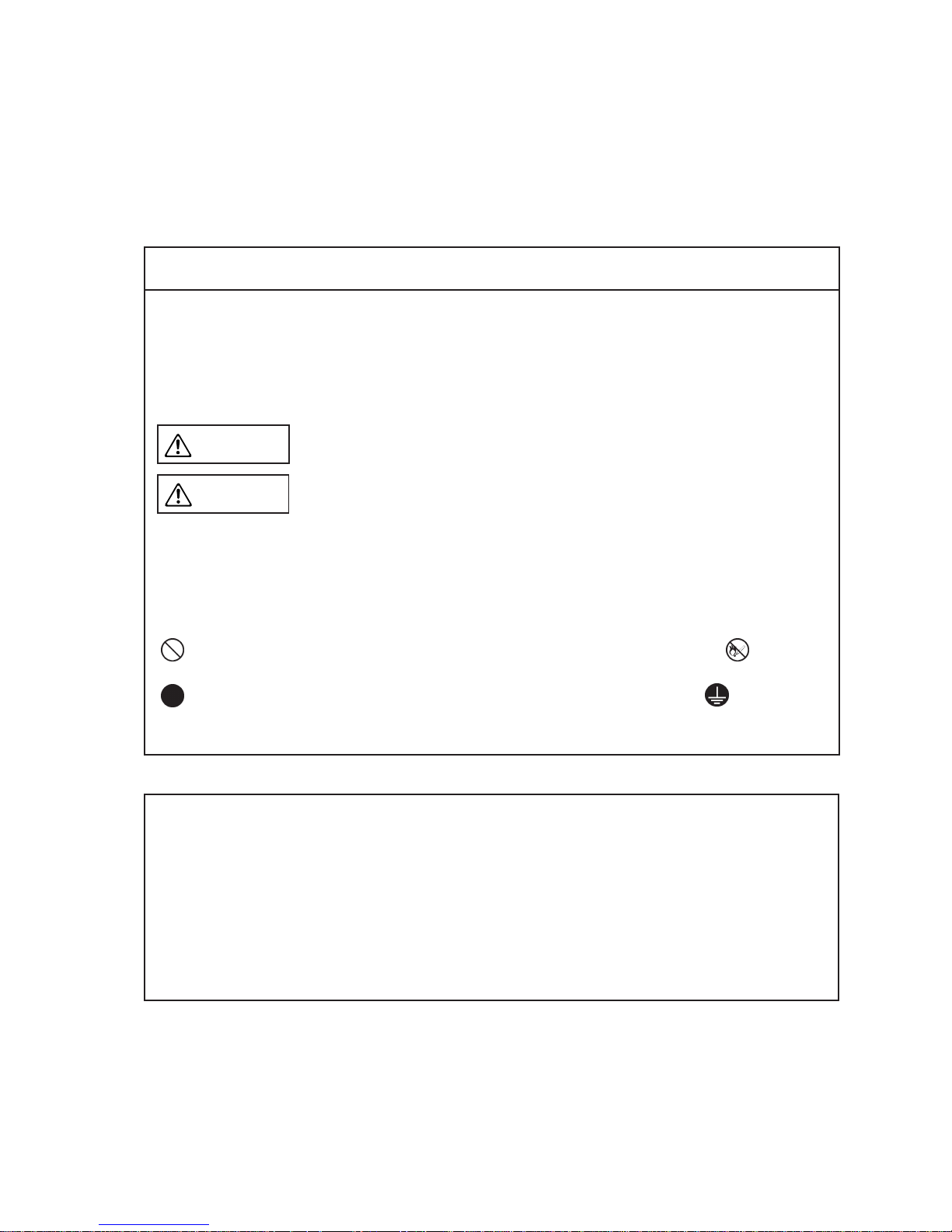
In this Installation guide, the safety instruction levels are classified into "WARNING" and "CAUTION".
Indicates that incorrect handling may cause hazardous conditions,, resulting in death or severe injury.
Indicates that incorrect handling may cause hazardous conditions,, resulting in medium or slight injury to personnel or may cause physical damage.
Note that the CAUTION level may lead to a serious consequence according to conditions. Please
follow the instructions of both levels because they are important to personnel safety.
What must not be done and what must be done are indicated by the following diagrammatic
symbols:
: Indicates what must not be done. For example, "No Fire" is indicated by .
: Indicates what must be done. For example, grounding is indicated by .
After reading this installation guide, always keep it accessible to the operator.
WARNING
CAUTION
In this Installation guide, instructions at a lower level than the above, instructions for other
functions, and so on are classified into "NOTICE", "INFORMATION" and "MEMORANDUM".
Indicates that incorrect handling may cause the servo amplifier to be faulty and may
not lead to physical damage.
Indicates that parameter setting change, etc. will provide another function or there
are other usages.
Indicates information needed for use of this equipment.
NOTICE
INFORMATION
MEMORANDUM
Page 3
– 2 –
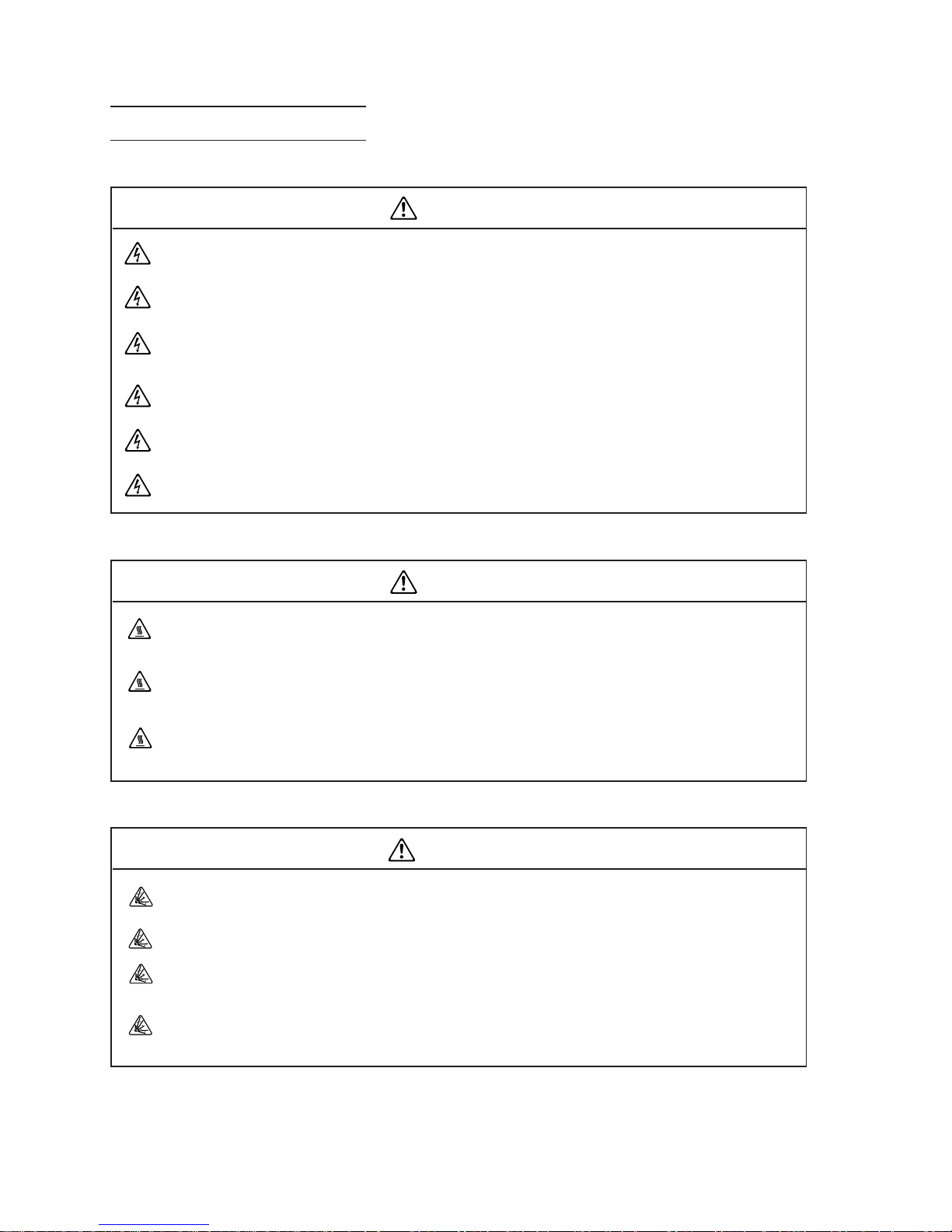
Before wiring or inspection, switch power off and wait for more than 10 minutes. Then,
confirm the voltage is safe with voltage tester. Otherwise, you may get an electric shock.
Connect the servo amplifier and servo motor to ground.
Any person who is involved in wiring and inspection should be fully competent to do the
work.
Do not attempt to wire the servo amplifier and servo motor until they have been installed.
Otherwise, you may get an electric shock.
Operate the switches with dry hand to prevent an electric shock.
The cables should not be damaged, stressed loaded,, or pinched. Otherwise, you may get
an electric shock.
Do not install the servo amplifier, servo motor and regenerative brake resistor on or near
combustibles. Otherwise a fire may cause.
When the servo amplifier has become faulty, switch off the main servo amplifier power
side. Continuous flow of a large current may cause a fire.
When a regenerative brake resistor is used, use an alarm signal to switch main power off.
Otherwise, a regenerative brake transistor fault or the like may overheat the regenerative
brake resistor, causing a fire.
SAFETY INSTRCUTIONS
1. To prevent electric shock, note the following:
WARNING
2. To prevent fire, note the following:
CAUTION
3. To prevent injury, note the following:
Only the voltage specified in the Installation guide should be applied to each terminal,,
Otherwise,, a burst,, damage,, etc. may occur.
Connect the terminals correctly to prevent a burst,, damage,, etc.
Ensure that polarity (+, -) is correct. Otherwise, a burst, damage, etc. may occur.
During power-on or for some time after power-off, do not touch the servo amplifier fins,
regenerative brake resistor, servo motor, etc. Their temperatures may be high and you
may get burnt.
CAUTION
Page 4
– 3 –
4. Additional instructions
The following instructions should also be fully noted. Incorrect handling may cause a fault, injury,
electric shock, etc.
(1) Transportation and installation
Transport the products correctly acordng to their weights.
Stacking in excess of the specified number of products is not allowed.
Do not carry the motor by the cables, shaft or encoder.
Do not hold the front cover to transport the controller. The controller may drop.
Install the servo amplifier in a load-bearing place in accordance with the Installation guide.
Do not climb or stand on servo equipment. Do not put heavy objects on equipment.
The controller and servo motor must be installed in the specified direction.
Leave specified clearances between the servo amplifier and control enclosure walls or
other equipment.
Do not install or operate the servo amplifier and servo motor which has been damaged or
has any parts missing.
Provide adequate protection to prevent screws and other conductive matter, oil and other
combustible matter from entering the servo amplifier.
Do not drop or strike servo amplifier or servo motor. Isolate from all impact loads.
CAUTION
Page 5
– 4 –
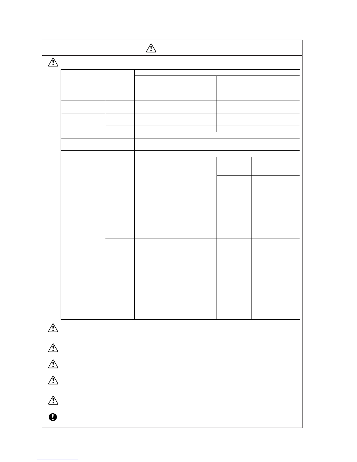
Use the servo amplifier and servo motor under the following environmental conditions:
Securely attach the servo motor to the machine. If attach insecurely, the servo motor may
come off during operation.
The servo motor with reduction gear must be installed in the specified direction to prevent
oil leakage.
For safety of personnel, always cover rotating and moving parts.
Never hit the servo motor or shaft, especially when coupling the servo motor to the ma-
chine. The encoder may become faulty.
Do not subject the servo motor shaft to more than the permissible load. Otherwise, the
shaft may break.
When the equipment has been stored for an extended period of time, consult Mitsubishi.
CAUTION
Servo Amplifier
Environmen
Conditions
Servo Motor
Ambient
temperature
Ambient humidity
Storage humidity
Ambience
Altitude
Vibration
Storage
temperature
0 to +55 (non-freezing)
32 to 131
(non-freezing)
90%RH or less
(non-condensing)
-20 to +65
(non-freezing)
-4 to 149 (non-freezing)
90%RH or less (non-condensing)
Indoors (no direct sunlight)
Free from corrosive gas, flammable gas, oil mist, dust and dirt
Max. 1000m (3280 ft) above sea level
5.9 (0.6G) or less
19.4 or less
[
°
C]
[
°
F]
[
°
C]
[°F]
[m/s
2
]
[ft/s
2
]
0 to +40 (non-freezing)
32 to 104
(non-freezing)
80%RH or less
(non-condensing)
-15 to +70
(non-freezing)
5 to 158 (non-freezing)
MC-MF series
HA-FF series
HU-UF13 to 43
HC-SF81
HC-SF52 to 152
HC-SF53 to 153
HC-RF series
HC-UF72 • 152
HC-SF121 • 201
HC-SF202 • 352
HC-SF203 • 353
HC-UF202
HC-SF301
MC-MF series
HA-FF series
HU-UF13 to 43
HC-SF81
HC-SF52 to 152
HC-SF53 to 153
HC-RF series
HC-UF72 • 152
HC-SF121 • 201
HC-SF202 • 352
HC-SF203 • 353
HC-UF202
HC-SF301
X • Y: 19.6(2G)
X: 9.8(1G)
Y: 24.5(2.5G)
X: 19.6(2G)
Y: 49(5G)
X: 11.7(1.2G) Y: 29.4(3G)
X • Y: 64
X: 32
Y: 80
X: 64 Y: 161
X: 38 Y: 96
Page 6

– 5 –
(2) Wiring
Wire the equipment correctly and securely. Otherwise, the servo motor may misoperate
Do not install a power capacitor, surge absorber or radio noise filter (FR-BIF option) be-
tween the servo motor and servo amplifier.
Connect the output terminals (U, V, W) correctly. Otherwise, the servo motor will operate
improperly.
Do not connect AC power directly to the servo motor. Other-
wise, a fault may occur.
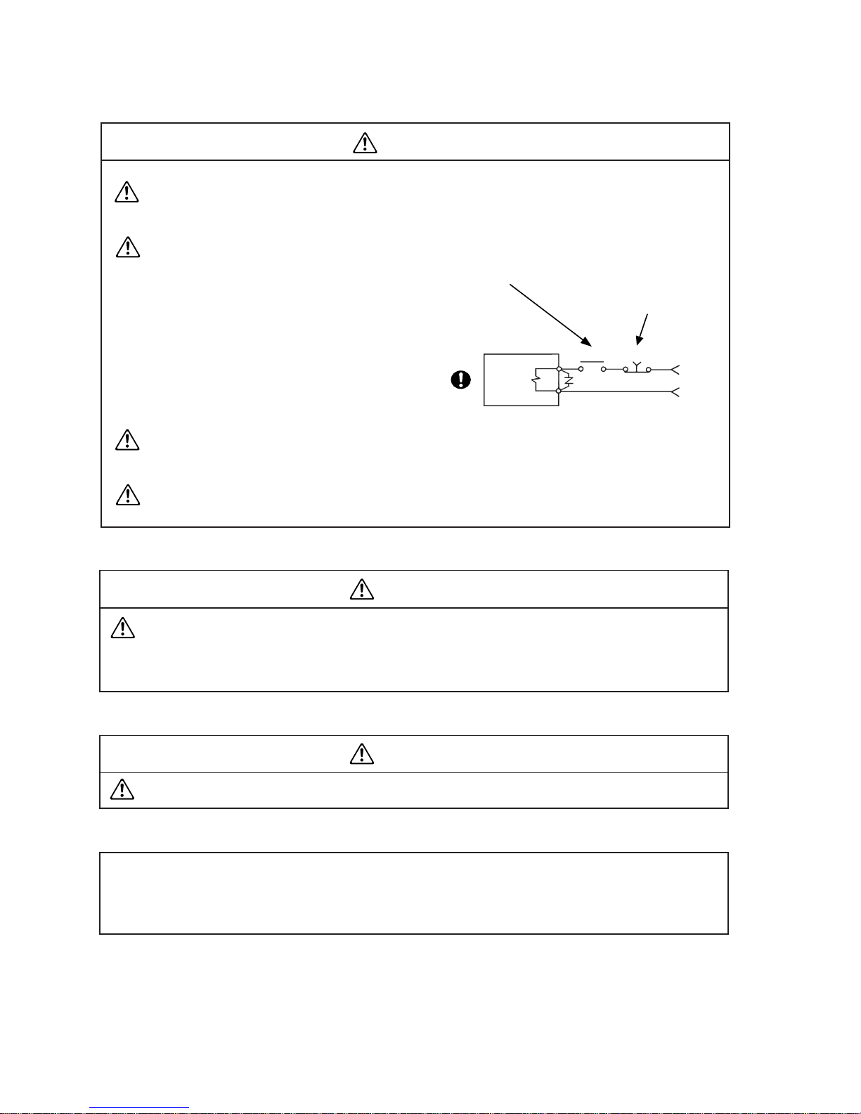
The surge absorbing diode installed on the DC output signal
relay must be wired in the specified direction. Otherwise,
the emergency stop and other protective circuits may not
operate.
CAUTION
Before operation, check the parameter settings. Improper settings may cause some
machines to perform unexpected operation.
The parameter settings must not be changed excessively. Operation will be instable.
CAUTION
(3) Test run adjustment
RA
SG
V+
ALM
PF
Servo
amplifier
(4) Usage
Provide an external emergency stop circuit to ensure that operation can be stopped and
power switched off immediately.
Any person who is involved in disassembly and repair should be fully competent to do the
work.
Before resetting an alarm, make sure that the run signal is off to prevent an accident. A
sudden restart is made if an alarm is reset with the run signal on.
Do not modify the equipment.
Use a noise filter, etc. to minimize the influence of electromagnetic interference, which
may be caused by electronic equipment used near the servo amplifier.
Use the servo amplifier with the specified servo motor.
The electromagnetic brake on the servo motor is designed to hold the motor shaft and
should not be used for ordinary braking.
For such reasons as service life and mechanical structure (e.g. where a ballscrew and the
servo motor are coupled via a timing belt), the electromagnetic brake may not hold the
motor shaft. To ensure safety, install a stopper on the machine side
CAUTION
Page 7
– 6 –
When it is assumed that a hazardous condition may take place at the occur due to a power
failure or a product fault,, use a servo motor with electromag<->netic brake or an external
brake mechanism for the purpose of prevention.
Configure the electromagnetic brake circuit so that it is activated not only by the servo
amplifier signals but also by an external emergency stop signal.
When any alarm has occurred,, eliminate its cause,, ensure safety,, then reset the alarm,,
before restarting operation.
When power is restored after an instantaneous power failure,, keep away from the machine
because the machine may be restarted suddenly (design the machine so that it is secured
against hazard if restarted).
CAUTION
(5) Corrective actions
RA1
EMG
24VDC
Electromagnetic brake
Servo motor
Contacts must be
open when servo
is off or when an
alarm (trouble) is
present.
Circuit must be
opened during
emergency stop.
(6) Maintenance, inspection and parts replacement
With age, the electrolytic capacitor will deteriorate. To prevent a secondary accident due
to a fault, it is recommended to replace the electrolytic capacitor every 10 years when
used in general environment.
Please consult our sales representative.
CAUTION
(7) Disposal
Dispose of the product as general industrial waste.
CAUTION
(8) General instruction
To illustrate details, the equipment in the diagrams of this Installation guide may have been
drawn without covers and safety guards. When the equipment is operated, the covers and safety
guards must be installed as specified. Operation must be performed in accordance with this
Installation guide.
Page 8
– 7 –
1. WHAT ARE EC DIRECTIVES?
The EC Directives were issued to standardize the regulations of the EU countries and ensure smooth
distribution of safety-guaranteed products. In the EU countries, the Machinery Directive (effective
in January, 1995), EMC Directive (effective in January, 1996) and Low Voltage Directive (effective
in January, 1997) of the EC Directives require that products to be sold should meet their fundamental safety requirements and carry the CE marks (CE marking). CE marking applies to machines and equipment into which servo amplifiers have been installed.
The servo amplifiers do not function independently but are designed for use with machines and
equipment. Therefore, the CE marking does not apply to the servo amplifiers but applies to the
machines and equipment into which the servo amplifiers are installed.
This servo amplifier conforms to the standards related to the Low Voltage Directive to facilitate CE
marking on machines and equipment into which the servo amplifiers will be installed. To ensure
ease of compliance with the EMC Directive, Mitsubishi Electric prepared the "EMC INSTALLATION
GUIDELINES" (IB(NA)67310) which provides servo amplifier installation, control box making and
other procedures. Please contact your sales representative.
2. PRECAUTIONS FOR COMPLIANCE
Use the standard model of servo amplifier and the EN Standard-compliant model of servo motor. In
addition to the instructions provided in this Installation Guide, also follow the instructions below.If
the model is not specifically described to comply with the EN Standard in this Installation Guide, it
has the same specifications as those of the standard models:
(1) Structure
(2) Environment
Operate the servo amplifier at or above the contamination level 2 set forth in IEC664. For this
purpose, install the servo amplifier in a control box which is protected against water, oil, carbon, dust, dirt, etc. (IP54).
(3) Power supply
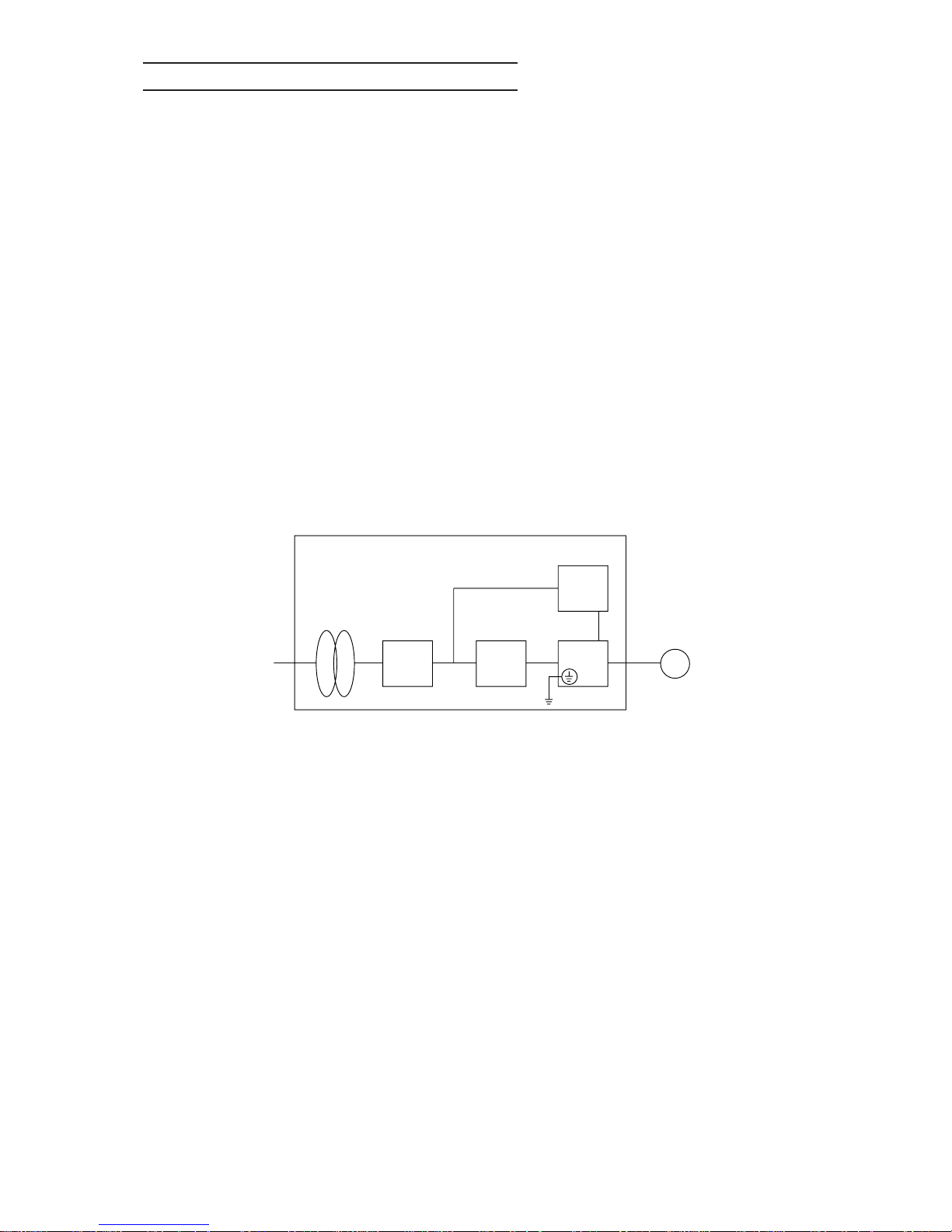
1) Operate the servo amplifier to meet the requirements of the overvoltage category II set forth
in IEC664. For this purpose, a reinforced insulating transformer conforming to the IEC or EN
Standard should be used in the power input section.
2) When supplying interface power from external, use a 24VDC power supply which has been
insulation-reinforced in I/O.
COMPLIANCE WITH EC DIRECTIVES
Servo
motor
Control box
Reinforced
insulating
transformer
No-fuse
breaker
Magnetic
contactor
Reinforced
insulating type
24VDC
power
supply
Servo
amplifier
SMMCNFB
Page 9

– 8 –
(4) Grounding
1) To prevent an electric shock, always connect the protective earth (PE) terminals (marked )
of the servo amplifier to the protective earth (PE) of the control box.
2) Do not connect two ground cables to the same protective earth (PE) terminal. Always connect the cables to the terminals one-to-one.
3) If a leakage current breaker is used to prevent an electric shock, the protective earth (PE)
terminals of the servo amplifier must be connected to the corresponding earth terminals.
(5) Wiring
1) The cables to be connected to the terminal block of the servo amplifier must have crimping
terminals provided with insulating tubes to prevent contact with adjacent terminals.
2) Use a fixed terminal block to connect the power supply lead of the HC-MF/HA-FF series
servo motor to the servo amplifier. Do not connect cables directly.
(6) Auxiliary equipment and options
1) The no-fuse breaker and magnetic contactor used should be the EN or IEC Standard-compliant products of the models described in Section 6-2-1.
2) The sizes of the cables described in Section 6-2-1 meet the following requirements. To meet
the other requirements, follow Table 5 and Appendix C in EN60204.
• Ambient temperature: 40 (104) [°C(°F)]
• Sheath: PVC (polyvinyl chloride)
• Installed on wall surface or open table tray
3) When the EMC filter is used, the radio noise filter (FR-BIF) described in (5), Section 6-2-6 is
not required.
(7) Servo motor
For outline dimension drawings not shown, contact Mitsubishi.
(8) Performing EMC tests
When EMC tests are run on a machine/device into which the servo amplifier has been installed,
it must conform to the electromagnetic compatibility (immunity/emission) standards after it has
satisfied the operating environment/electrical equipment specifications.
For the other EMC Directive guidelines on the servo amplifier, refer to the "EMC INSTALLATION GUIDELINES".
PE terminalsPE terminals
Terminal block
Crimping terminal
Insulating tube
Cable
Page 10
– 9 –
Use the servo amplifiers and servo motors which comply with the UL/C-UL Standard.
Unless otherwise specified, the handling, performance, specifications, etc. of the UL/C-UL Standard-compliant models are the same as those of the standard models.
When using the options and auxiliary equipment, use those which confrom to the UL/C-UL Standard.
INSTRUCTIONS FOR COMPLIANCE WITH THE UL/C-UL STANDARD
To comply with the UL/C-UL Standard, strictly observe the following:
CONFORMANCE WITH UL/C-UL STANDARD
(1) Installation
Install a fan of 100CFM air flow 10.16 cm (4 in) above the servo amplifier or provide cooling of
at least equivalent capability.
(2) Short-circuit rating
Having been subjected to UL's short-circuit test with an AC circuit whose peak current is limited
to 5000A max., this servo amplifier complies with this circuit.
(3) Flange
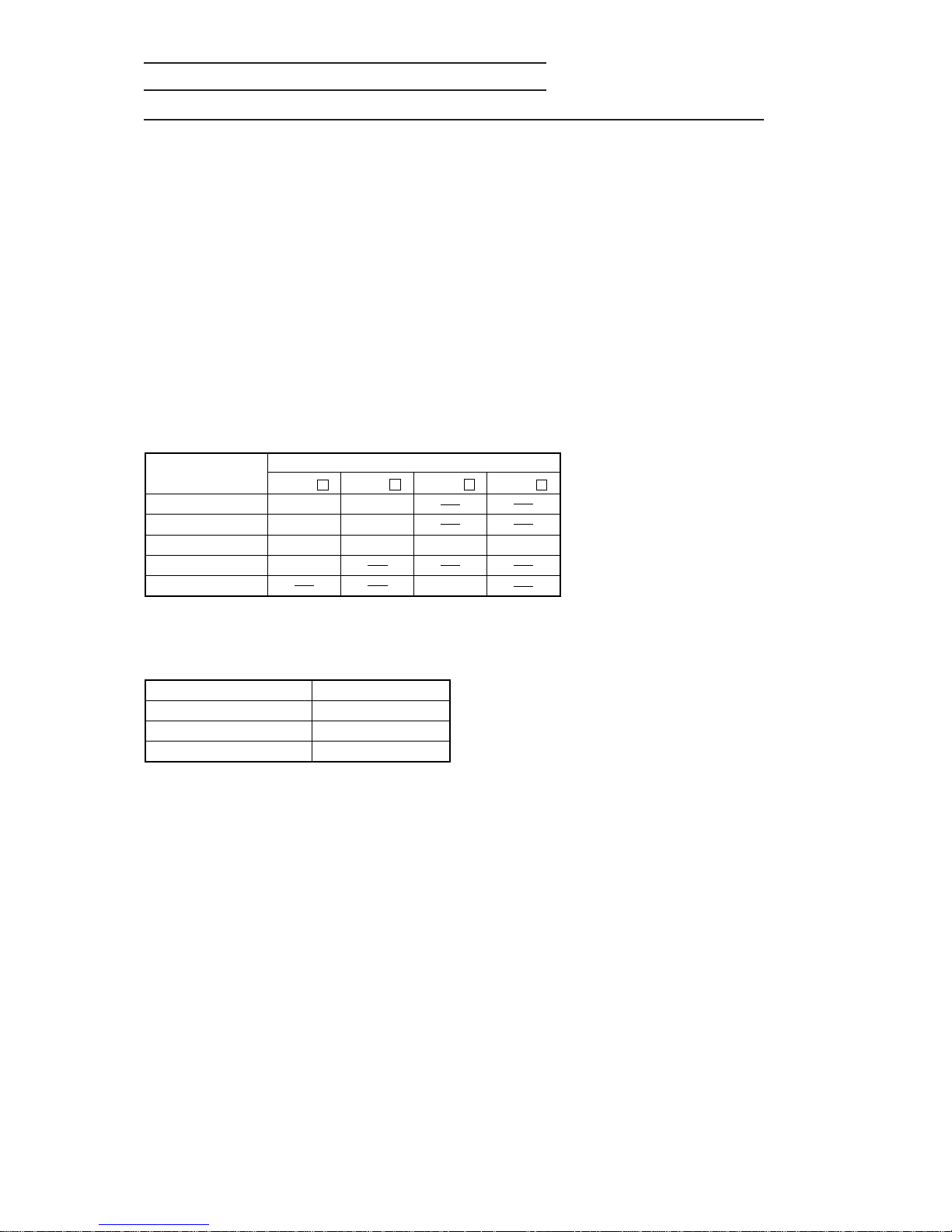
Mount the servo motor on a flange which has the following size or produces an equivalent or
higher heat dissipation effect:
(4) Capacitor discharge time
The capacitor discharge time is as listed below. To ensure safety, do not touch the charging
section for 10 minutes after power-off.
Flange Size
[mm]
150 x 150 x 6
250 x 250 x 6
250 x 250 x 12
300 x 300 x 12
300 x 300 x 20
HC-MF
053 • 13
23
43
73
Servo Motor
HA-FF
053 • 13
23 • 33
43 • 63
HC-SF
52~152
202 • 352
HC-RF
103~203
Servo Amplifier
MR-J2-10A(1)•20A(1)
MR-J2-40A(1)•60A
MR-J2-70A~350A
Discharge Time [min]
1
2
3
Page 11

i
CONTENTS
CHAPTER 1 INTRODUCTION ................................................................................................. 1-1~1-17
1-1 Inspection at Delivery.............................................................................................................1-2
1-1-1 Packing list.................................................................................................................1-2
1-1-2 Model definition .........................................................................................................1-2
1-1-3 Combination with Servo Motor ............................................................................... 1-7
1-2 Parts Identification and Applications................................................................................... 1-8
1-2-1 Servo amplifier ..........................................................................................................1-8
1-2-2 Servo motor............................................................................................................. 1-13
1-3 Function List.......................................................................................................................... 1-14
1-4 Basic Configuration .............................................................................................................. 1-15
1-4-1 MR-J2-100A or less ............................................................................................... 1-15
1-4-2 MR-J2-200A or more ............................................................................................. 1-17
CHAPTER 2 OPERATION ........................................................................................................ 2-1~2-54
2-1 Standard Connection Examples........................................................................................... 2-2
2-1-1 Position control mode.............................................................................................. 2-2
2-1-2 Speed control mode................................................................................................. 2-6
2-1-3 Torque control mode ................................................................................................ 2-8
2-2 Operation ................................................................................................................................ 2-10
2-2-1 Pre-operation checks ............................................................................................. 2-10
2-2-2 Start-up.................................................................................................................... 2-11
2-3 Display and Operation......................................................................................................... 2-18
2-3-1 Display flowchart.................................................................................................... 2-18
2-3-2 Status display ......................................................................................................... 2-19
2-3-3 Diagnostic mode ..................................................................................................... 2-20
2-3-4 Alarm mode............................................................................................................. 2-27
2-3-5 Parameter mode..................................................................................................... 2-28
2-4 Adjustments........................................................................................................................... 2-50
2-4-1 Auto tuning.............................................................................................................. 2-50
2-4-2 Manual gain adjustment ........................................................................................ 2-50
2-4-3 Slight vibration suppression control .................................................................... 2-54
CHAPTER 3 WIRING ................................................................................................................. 3-1~3-62
3-1 Servo Amplifier ........................................................................................................................3-3
3-1-1 Terminal blocks .........................................................................................................3-3
3-1-2 Signal connectors..................................................................................................... 3-6
3-1-3 Detailed information on I/O signals ..................................................................... 3-18
3-1-4 Interfaces ................................................................................................................ 3-32
3-2 Connection of Servo Amplifier and Servo Motor .............................................................3-36
3-2-1 Connection instructions......................................................................................... 3-36
3-2-2 Connection diagram............................................................................................... 3-37
3-2-3 I/O terminals ........................................................................................................... 3-38
3-2-4 Connectors used for Servo Motor wiring ............................................................3-41
3-3 Common Line........................................................................................................................ 3-55
3-4 Grounding ...............................................................................................................................3-56
3-5 Power Supply Circuit ........................................................................................................... 3-57
3-6 Alarm Occurrence Timing Chart ......................................................................................... 3-59
3-7 Servo Motor with Electromagnetic Brake.......................................................................... 3-60
CHAPTER 4 INSTALLATION ......................................................................................................4-1~4-9
4-1 Servo Amplifier ...........................................................................................................................4-2
4-2 Servo Motor.................................................................................................................................4-5
Page 12

ii
CHAPTER 5 ABSOLUTE POSITION DETECTION SYSTEM................................................ 5-1~5-6
CHAPTER 6 OPTIONS AND AUXILIARY EQUIPMENT ...................................................... 6-1~6-27
6-1 Dedicated Options ...................................................................................................................6-2
6-1-1 Regenerative brake options .................................................................................... 6-2
6-1-2 Cable connectors ..................................................................................................... 6-7
6-1-3 Junction terminal block.......................................................................................... 6-14
6-1-4 Maintenance junction card.................................................................................... 6-15
6-1-5 Set-up software ...................................................................................................... 6-16
6-2 Auxiliary Equipment ............................................................................................................. 6-17
6-2-1 Cables...................................................................................................................... 6-17
6-2-2 No-fuse breakers, fuses, magnetic contactors ..................................................6-17
6-2-3 Power factor improving reactors.......................................................................... 6-18
6-2-4 Relays...................................................................................................................... 6-18
6-2-5 Surge absorbers..................................................................................................... 6-19
6-2-6 Noise reduction techniques .................................................................................. 6-20
6-2-7 Leakage current breaker....................................................................................... 6-25
6-2-8 Battery (MR-BAT, A6BAT) .................................................................................... 6-26
6-2-9 Setting potentiometers for analog inputs ............................................................ 6-27
CHAPTER 7 INSPECTION ..........................................................................................................7-1~7-3
CHAPTER 8 TROUBLESHOOTING........................................................................................ 8-1~8-13
8-1 Troubleshooting at Start-Up ................................................................................................. 8-2
8-1-1 Position control mode.............................................................................................. 8-2
8-1-2 Speed control mode................................................................................................. 8-4
8-1-3 Torque control mode ................................................................................................ 8-5
8-2 Alarms and Warnings..............................................................................................................8-6
8-2-1 Alarm and warning list............................................................................................. 8-6
8-2-2 Alarms.........................................................................................................................8-7
8-2-3 Warnings ................................................................................................................. 8-13
CHAPTER 9 CHARACTERISTICS .......................................................................................... 9-1~9-12
9-1 Overload Protection Characteristics .................................................................................... 9-2
9-2 Losses Generated in the Servo Amplifier........................................................................... 9-4
9-3 Electromagnetic Brake Characteristics............................................................................... 9-6
9-4 Dynamic Brake Characteristics.......................................................................................... 9-10
9-5 Vibration Rank ...................................................................................................................... 9-12
CHAPTER 10 SPECIFICATIONS........................................................................................... 10-1~10-79
10-1 Standard Specifications ...................................................................................................... 10-2
10-2 Torque Characteristics ........................................................................................................ 10-6
10-3 Servo Motors with Reduction Gears................................................................................ 10-10
10-4 Servo Motors with Special Shafts.................................................................................... 10-14
10-5 Outline Dimension Drawings ............................................................................................10-16
10-5-1 Servo amplifiers ................................................................................................... 10-16
10-5-2 Servo motors......................................................................................................... 10-19
10-5-3 Servo motors (in inches)..................................................................................... 10-46
10-5-4 Cable side plugs ................................................................................................... 10-73
Page 13

iii
CHAPTER 11 SELECTION..................................................................................................... 11-1~11-13
11-1 Specification Symbol List.................................................................................................... 11-2
11-2 Position Resolution and Electronic Gear Setting ............................................................ 11-3
11-3 Speed and Command Pulse Frequency ............................................................................ 11-4
11-4 Stopping Characteristics..................................................................................................... 11-5
11-5 Capacity Selection ............................................................................................................... 11-6
11-6 Load Torque Equations ....................................................................................................... 11-8
11-7 Load Inertia Moment Equations ......................................................................................... 11-9
11-8 Precautions for Zeroing..................................................................................................... 11-10
11-9 Selection Example.............................................................................................................. 11-11
Page 14
1– 1
CHAPTER 2
CHAPTER 3
CHAPTER 4
CHAPTER 5
CHAPTER 6
CHAPTER 7
CHAPTER 8
CHAPTER 9
CHAPTER 10
CHAPTER 11
INTRODUCTION
OPERATION
WIRING
INSTALLATION
ABSOLUTE POSITION DETECTION SYSTEM
OPTIONS AND AUXILIARY EQUIPMENT
INSPECTION
TROUBLESHOOTING
CHARACTERISTICS
SPECIFICATIONS
SELECTION
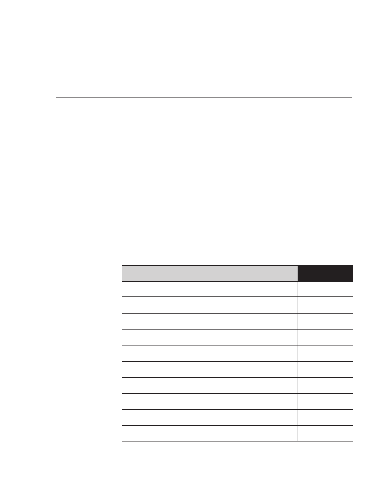
This chapter provides basic information needed to use this servo.
1-1 Inspection at Delivery
1-1-1 Packing list
1-1-2 Model definition
1-1-3 Combination with Servo Motor
1-2 Parts Identification and Applications
1-2-1 Servo amplifier
1-2-2 Servo motor
1-3 Function List
1-4 Basic Configuration
1-4-1 MR-J2-100A or less
1-4-2 MR-J2-200A or more
CHAPTER 1
CHAPTER 1
INTRODUCTION
Page 15
1. INTRODUCTION
1– 2
1-1 Inspection at Delivery
After unpacking, check the name plate to make sure that the servo amplifier and servo motor received are as ordered by the customer.
1) Servo amplifier
Item
Servo amplifier
(Note)Control circuit connector
Qty
1
1
1
2) Servo motor
Item
Servo motor
Qty
1
1
Safety Instructions
for Use of AC Servo
Specifications and
installation guide
Note: Not supplied to the servo amplifier of MR-J2-200A or more.
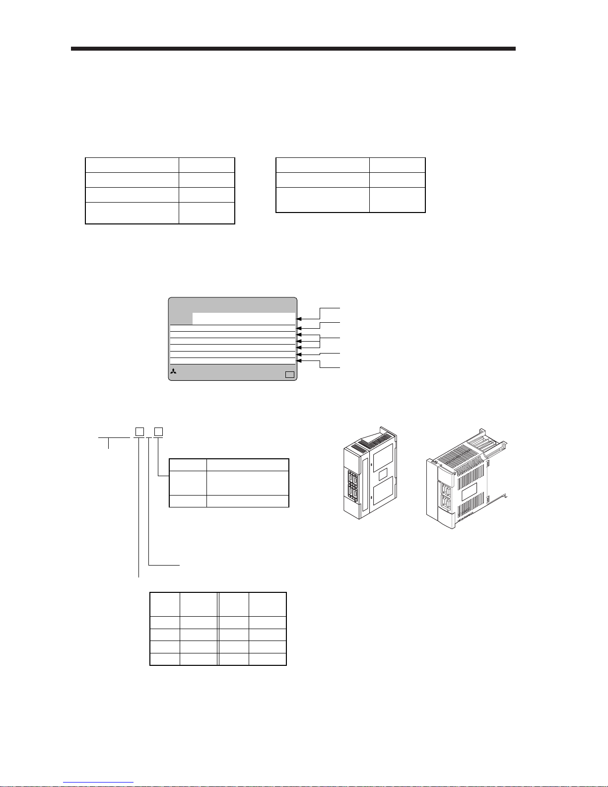
1-1-2 Model definition
1-1-1 Packing list
(1) Servo amplifier
1) Name plate
2) Model
Model
Capacity
Applicable power suppl
Rated output current
Current status + serial number
MITSUBISHI
AC SERVO
MADE IN JAPAN
MITSUBISHI ELECTRIC CORPORATION
MODEL
NB
MR-J2-60A
Series
MR-J2- A
General-purpose AC servo
Rated output
Symbol
None
(Note 1) 1
Power Supply
Three-phase 200V
(Note 2) Single-phase 230V
Single-phase 100V
Symbol
10
20
40
60
Rated
output [W]
100
200
400
600
Symbol
70
100
200
350
Rated
output [W]
750
1000
2000
3500
Note: 1. Not supplied to the servo amplifier
of MR-J2-60A or more.
Note: 2. Not supplied to the servo amplifier
of MR-J2-100A or more.
POWER : 600W
INPUT : 3.2A 3PH+1PH200 – 230V 50Hz
3PH+1PH200 – 230V 60Hz
5.5A 1PH 230V 50/60Hz
OUTPUT: 170V 0 – 360Hz 3.6A
SERIAL : TC3XXAAAAG52
MR-J2-100A or less
MR-J2-200A•350A
Page 16
1. INTRODUCTION
1
1– 3
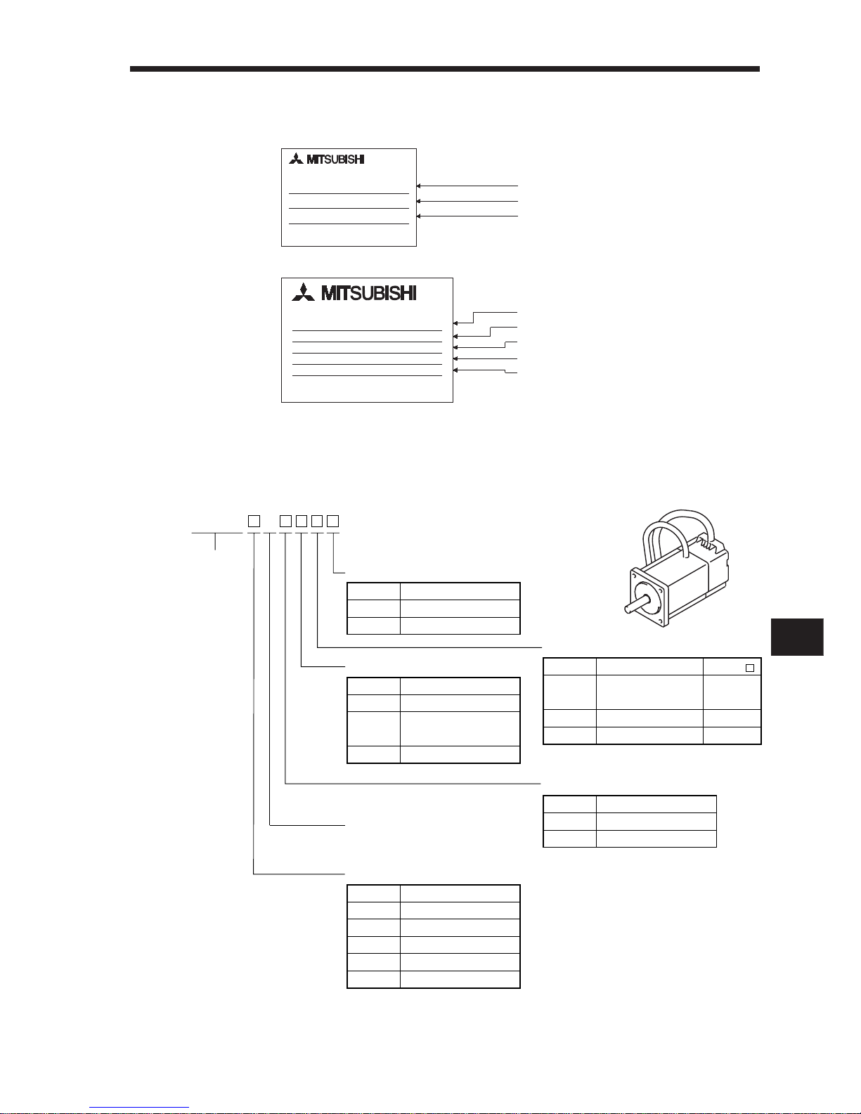
(2) Servo Motors
1) Name plate
AC SERVO MOTOR
HC-MF13
SERIAL
DATE
MITSUBISHI ELECTRIC CORPORATION
MADE IN JAPAN
AC SERVO MOTOR
HC-RF153
INPUT 3AC 145V 8.2A
MITSUBISHI ELECTRIC CORPORATION
MADE IN JAPAN
SPEED 3000r/min
SER.No. 001 DATE
OUTPUT 1.5Kw IEC34-1 1994
or
Model
Serial number
Input power
Rated output
Rated speed
Model
Serial number
Date of manufacture
2) Model
a. HC-MF series (ultra low inertia, small capacity)
Appearance
Series name
HC-MF 3
6) Rated output
5) Rated speed
3000 [r/min]
4) Electromagnetic brake
3) Reduction gear
2) Shaft type
1) Compliance with Standard
Symbol
None
-UE
Specifications
Standard model (Japan)
EN • UL/C-UL Standard
Note: With key
Symbol
05
1
2
4
7
Rated Output [W]
50
100
200
400
750
Symbol
None
B
Electromagnetic Brake
Without
With
Symbol
None
G1
G2
Reduction Gear
Without
For general
industrial machine
For precision application
Symbol
None
K
D
Shaft Shape
Standard
(Straight shaft)
(Note) With keyway
D-cut shaft
HC-MF
053 to 73
23 to 73
53 • 13
Page 17
1. INTRODUCTION
1– 4
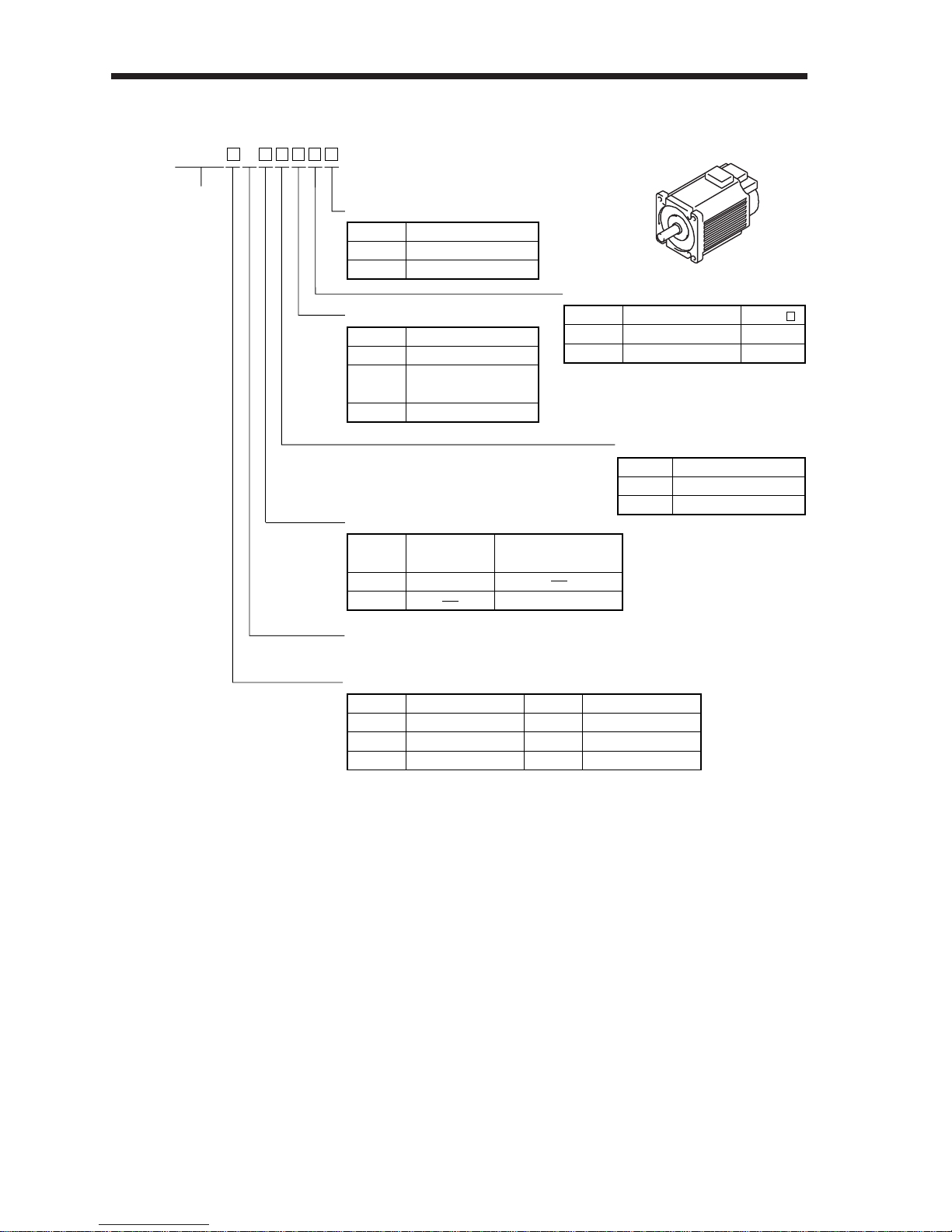
b. HA-FF series (low inertia, small capacity)
Appearance
Series name
HA-FF 3
7) Rated output
5) Input power supply form
6) Rated speed
3000 [r/min]
4) Electromagnetic brake
3) Reduction gear
2) Shaft type
1) Compliance with Standard
Symbol
None
-UE
Specifications
Standard model (Japan)
EN • UL/C-UL Standard
Symbol
05
1
2
Rated Output [W]
50
100
200
Symbol
3
4
6
Rated Output [W]
300
400
600
Symbol
None
B
Electromagnetic Brake
Without
With
Symbol
None
G1
G2
Reduction Gear
Without
For general
industrial machine
For precision application
Symbol
None
C
Standard model
Lead
EN • UL/C-UL Standard-
compliant model
Cannon connector
Symbol
None
D
Shaft Shape
(Note) Standard
D-cut shaft
HA-FF
053 to 73
053 • 13
Note: The Standard shafts of the HA-FF23 to
63 are with keys and those of the other
models are straight shafts.
Page 18
1. INTRODUCTION
1
1– 5
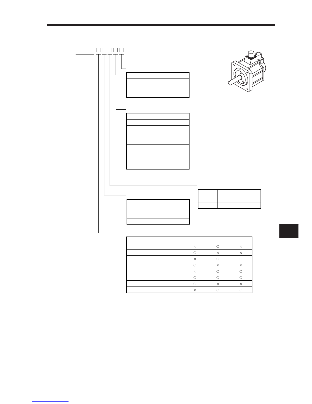
c. HC-SF series (middle inertia, middle capacity)
Appearance
Series name
HC-SF
5) Rated output
4) Rated speed
3) Electromagnetic brake
2) Reduction gear
1) Shaft type
Symbol
None
K
Shaft shape
Standard
(Straight shaft)
With keyway
Note: Without key
Symbol
5
8
10
12
15
20
30
35
Rated Output [W]
500
850
1000
1200
1500
2000
3000
3500
1000 [r/min] 2000 [r/min] 3000 [r/min]
Symbol
1
2
3
Speed [r/min]
1000
2000
3000
Symbol
None
B
Electromagnetic Brake
Without
With
Symbol
None
G1
G1H
G2
(Note) Reduction Gear
Without
For general
industrial machine
(flange type)
For general
industrial machine
(leg type)
For precision application
Note: Not provided for 1000r/min and
3000r/min series.
Page 19
1. INTRODUCTION
1– 6
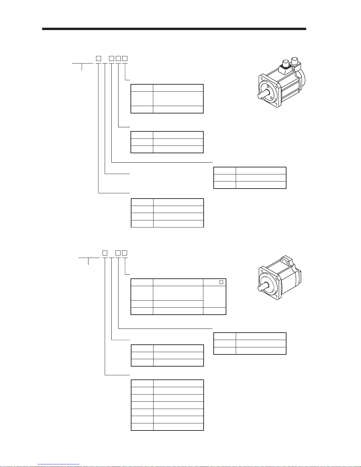
d. HC-RF series (low inertia, middle capacity)
Appearance
Series name
HC-RF 3
5) Rated output
3) Electromagnetic brake
2) Reduction gear
1) Shaft type
Symbol
None
K
Shaft Shape
Standard
(Straight shaft)
With keyway
Note: Without key
Symbol
10
15
20
Rated Output [W]
1000
1500
2000
Symbol
None
B
Electromagnetic Brake
Without
With
Symbol
None
G2
Reduction Gear
Without
For precision application
4) Rated speed
3000 [r/min]
e. HC-UF series (pancake type small capacity)
Appearance
Series name
HC-UF 3
4) Rated output
2) Electromagnetic brake
1) Shaft type
Symbol
None
K
D
Shaft Shape
Standard
(Straight shaft)
With keyway
D-cut shaft
HU-UF
13 to 43
72 to 202
13
Note: Without key
Symbol
1
2
4
7
15
20
Rated Output [W]
100
200
400
750
1500
2000
Symbol
2
3
Speed [r/min]
2000
3000
Symbol
None
B
Electromagnetic Brake
Without
With
3) Rated speed
Page 20

1. INTRODUCTION
1
1– 7
1-1-3 Combination with Servo Motor
The following table lists combinations of servo amplifiers and servo motors. The same combinations
apply to the models with electromagnetic brakes, the models with reduction gears, the EN Standardcompliant models and UL/C-UL Standard-compliant models.
Servo Amplifier
MR–J2–10A (1)
MR–J2–20A (1)
MR–J2–40A (1)
MR–J2–60A
MR–J2–70A
MR–J2–100A
MR–J2–200A
MR–J2–350A
053 • 13
23
43
73
053 • 13
23
33 • 43
63
81
121 • 201
301
52
102
152 • 202
352
53
103
153 • 203
353
103 • 153
203
72
152
202
13
23
43
73
Servo Motors
1000r/min 2000r/min 3000r/min 2000r/min 3000r/min
HC-MF HA-FF HC-RF
HC-SF (Note 2) HC-UF (Note 1)
Note 1. The HC-UF73 may not be connected depending on the production timing of the servo amplifier. Please contact us.
2. The HC-SF203 and 353 will be released soon.
Page 21
1. INTRODUCTION
1– 8
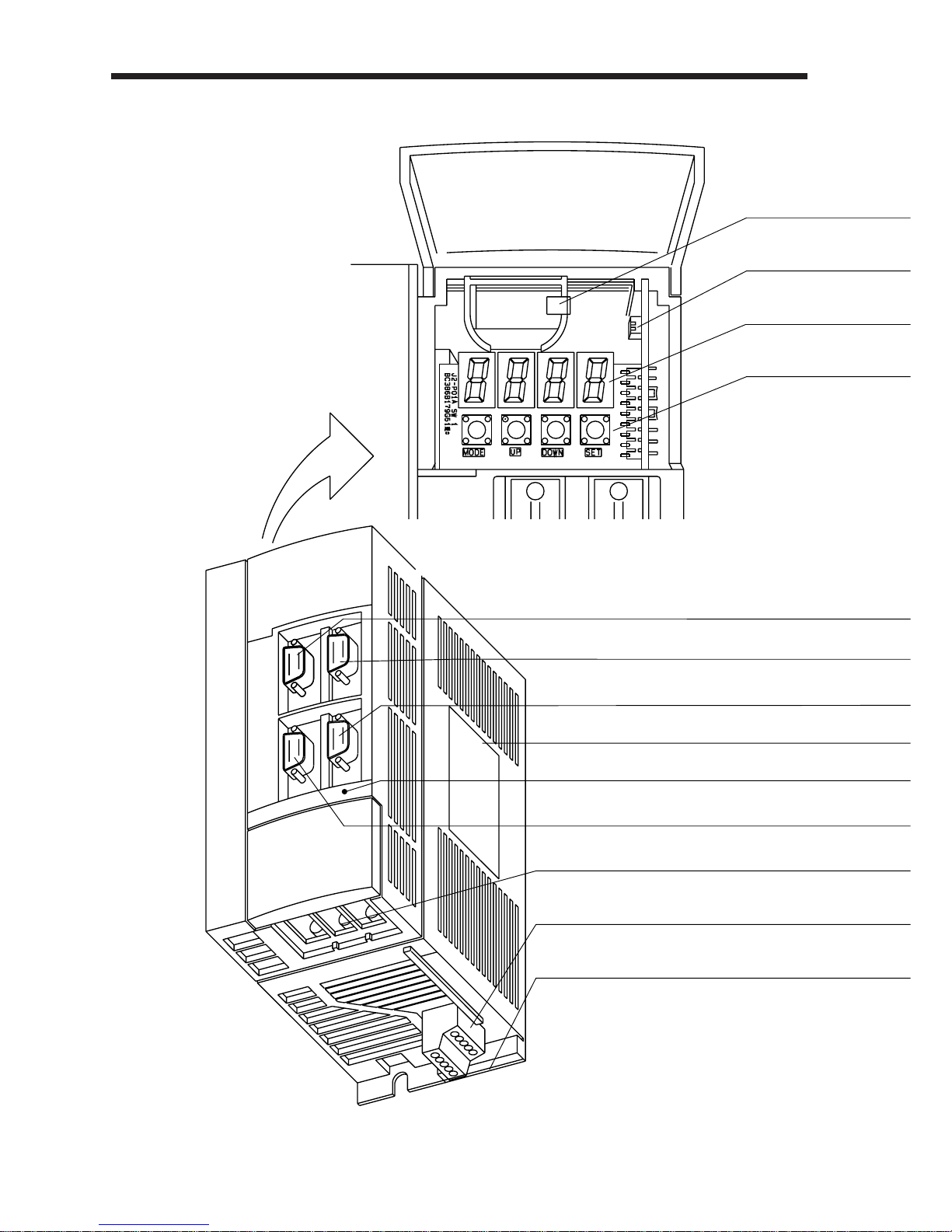
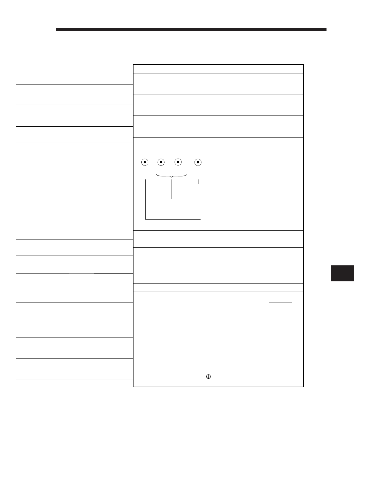
1-2-1 Servo amplifier
(1) MR-J2-200A or less
1-2 Parts Identification and Applications
Page 22
1. INTRODUCTION
1
1– 9
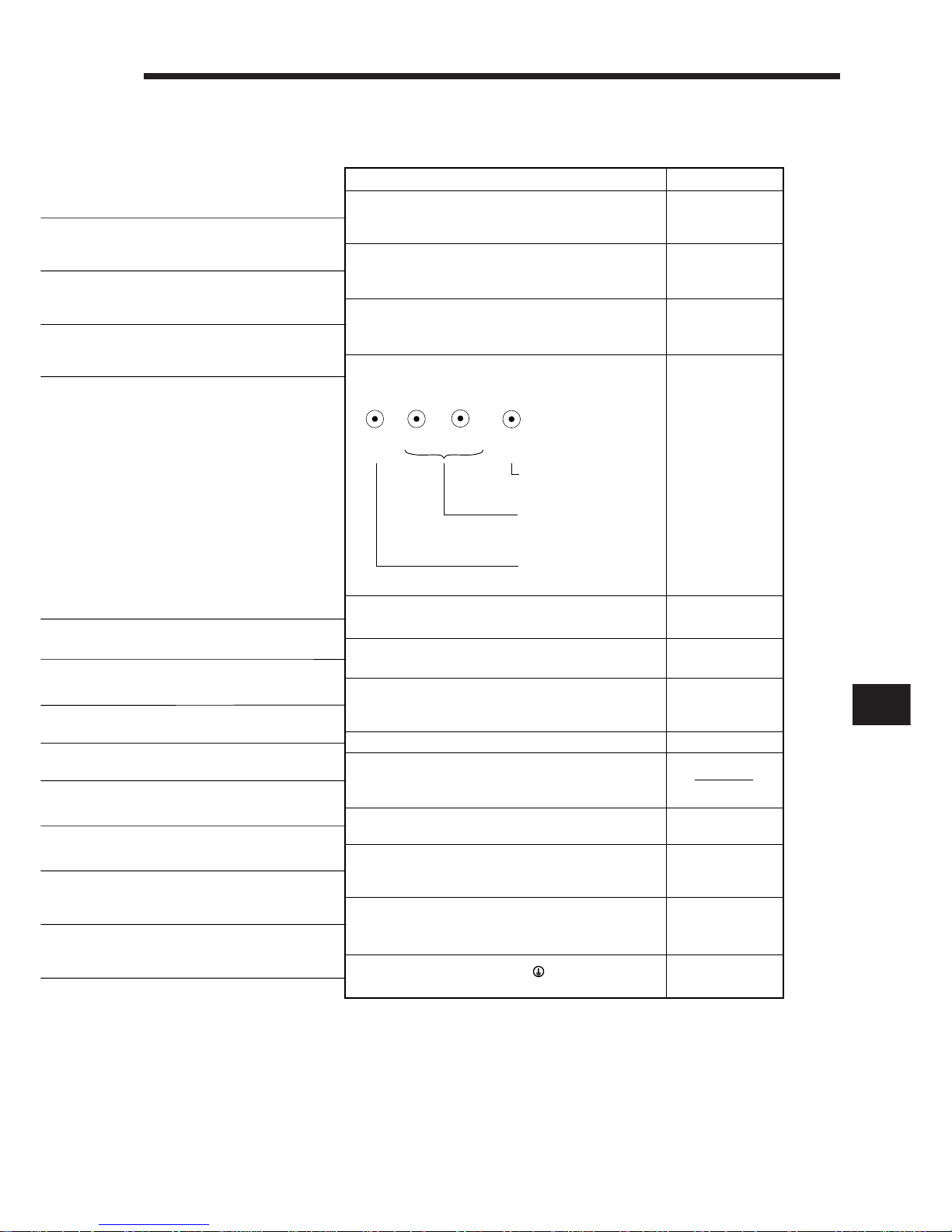
Used to set parameter
data.
Used to change the
display or data in each
mode.
Used to change the
mode.
Refer To
Chapter 5(5)
Section 6-2-8
Chapter 5(5)
Section 2-3
Section 2-3
Section 1-1
Section 3-1-2
Section 6-1-5
Section 3-1-2
Section 3-1-2
Section 3-1-2
Section 3-1-1
Section 3-1-1
Section 3-4
Name/Application
Battery holder
Contains the battery for absolute position data
backup.
Battery connector (CON1)
Used to connect the battery for absolute position
data backup
.
Display
The four-digit, seven-segment LED shows the servo
status and alarm number.
Operation section
Used to perform status display, diagnostic, alarm and
parameter setting operations.
MODE
UP
DOWN
SET
I/O signal connector (CN1A)
Used to connect digital I/O signals.
I/O signal connector (CN1B)
Used to connect digital I/O signals.
Communication connector (CN3)
Used to connect a personal computer or output
analog monitor.
Name plate
Charge lamp
Lit to indicate that the main circuit is charged. While
this lamp is lit, do not reconnect the cables.
Encoder connector (CN2)
Connector for connection of the servo motor encoder
Main circuit terminal block (TE1)
Used to connect the input power supply and servo
motor.
Control circuit terminal block (TE2)
Used to connect the control circuit power supply and
regenerative brake option.
Protective earth (PE) terminal ( )
Ground terminal.
Page 23
1. INTRODUCTION
1– 10
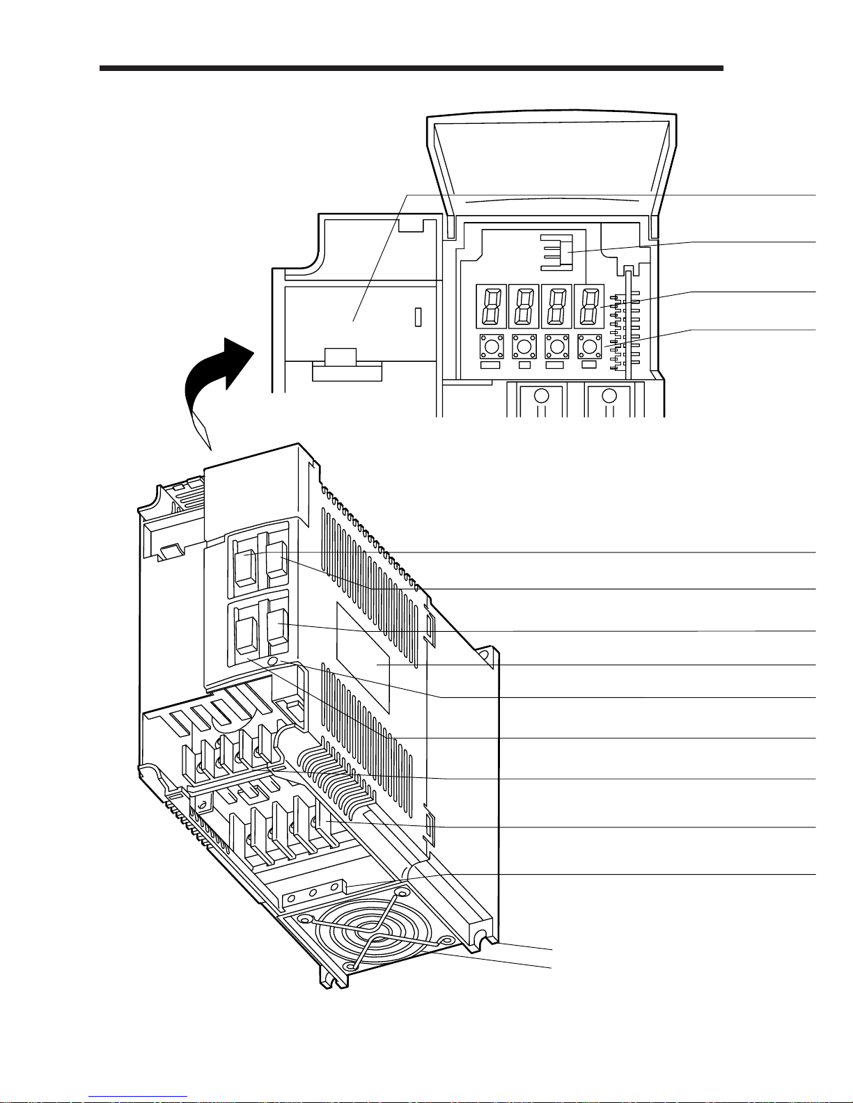
(2) MR-J2-200A or more
Installation notch (4 places)
Cooling fan
The servo amplifier is shown
without the front cover. For
removal of the front cover, refer
to page 1-12.
MODE
UP
DOWN
SET
Page 24
1. INTRODUCTION
1
1– 11
Used to set parameter
data.
Used to change the
display or data in each
mode.
Used to change the
mode.
Refer To
Chapter 5(5)
Section 6-2-8
Chapter 5(5)
Section 2-3
Section 2-3
Section 1-1
Section 3-1-2
Section 6-1-5
Section 3-1-2
Section 3-1-2
Section 3-1-2
Section 3-1-1
Section 3-1-1
Section 3-4
Name/Application
Battery holder
Contains the battery for absolute position data
backup.
Battery connector (CON1)
Used to connect the battery for absolute position
data backup
.
Display
The four-digit, seven-segment LED shows the servo
status and alarm number.
Operation section
Used to perform status display, diagnostic, alarm and
parameter setting operations.
MODE
UP
DOWN
SET
I/O signal connector (CN1A)
Used to connect digital I/O signals.
I/O signal connector (CN1B)
Used to connect digital I/O signals.
Communication connector (CN3)
Used to connect a personal computer or output
analog monitor.
Name plate
Charge lamp
Lit to indicate that the main circuit is charged. While
this lamp is lit, do not reconnect the cables.
Encoder connector (CN2)
Connector for connection of the servo motor encoder
Control circuit terminal block (TE2)
Used to connect the control circuit power supply and
regenerative brake option.Control circuit terminal
Main circuit terminal block (TE1)
Used to connect the input power supply and servo
motor.
Protective earth (PE) terminal ( )
Ground terminal.
Page 25
1. INTRODUCTION
1– 12
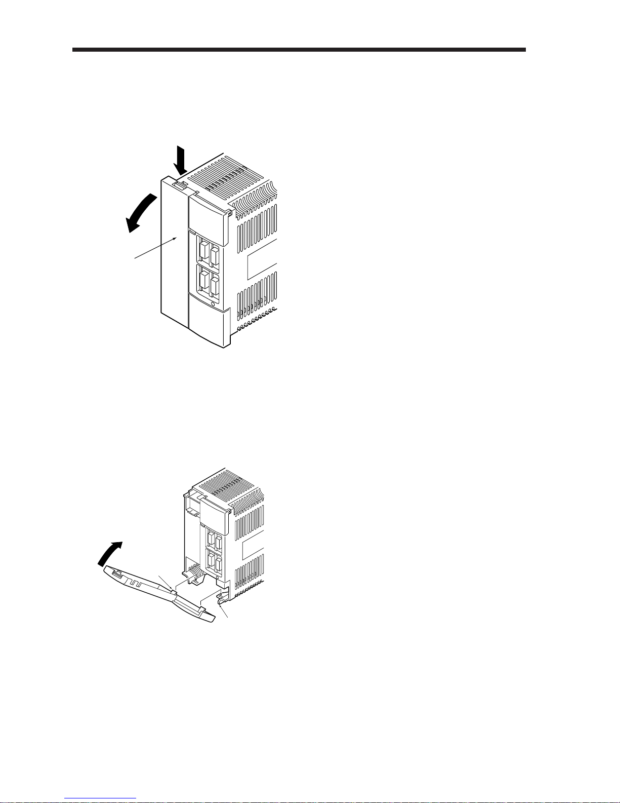
Removal of the front cover
q
w
Front cover
Reinstallation of the front cover
w
q
Front cover hook
(2 places)
Front cover socket (2 places)
1) Hold down the removing knob.
2) Pull the front cover toward you.
1) Insert the front cover hooks into
the front cover sockets of the
servo amplifier.
2)
Press the front cover against the
servo amplifier until the removing
knob clicks.
Page 26
1. INTRODUCTION
1
1– 13
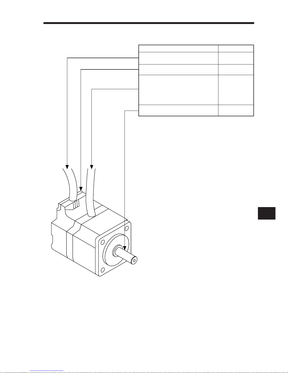
1-2-2 Servo motor
Refer To
Section 6-1-2
Section 3-2
Section 10-1
Section 3-2
Section 4-2 (4)
Section 10-4
Name/Application
Encoder cable
Encoder connector for HC-SF/HC-RF
Encoder
Power cable
• Power leads (U, V, W)
• Earth lead
• Brake lead
(For motor with electromagnetic brake)
Power supply connector for HC-SF/HC-RF
Servo motor shaft
Page 27
1. INTRODUCTION
1– 14
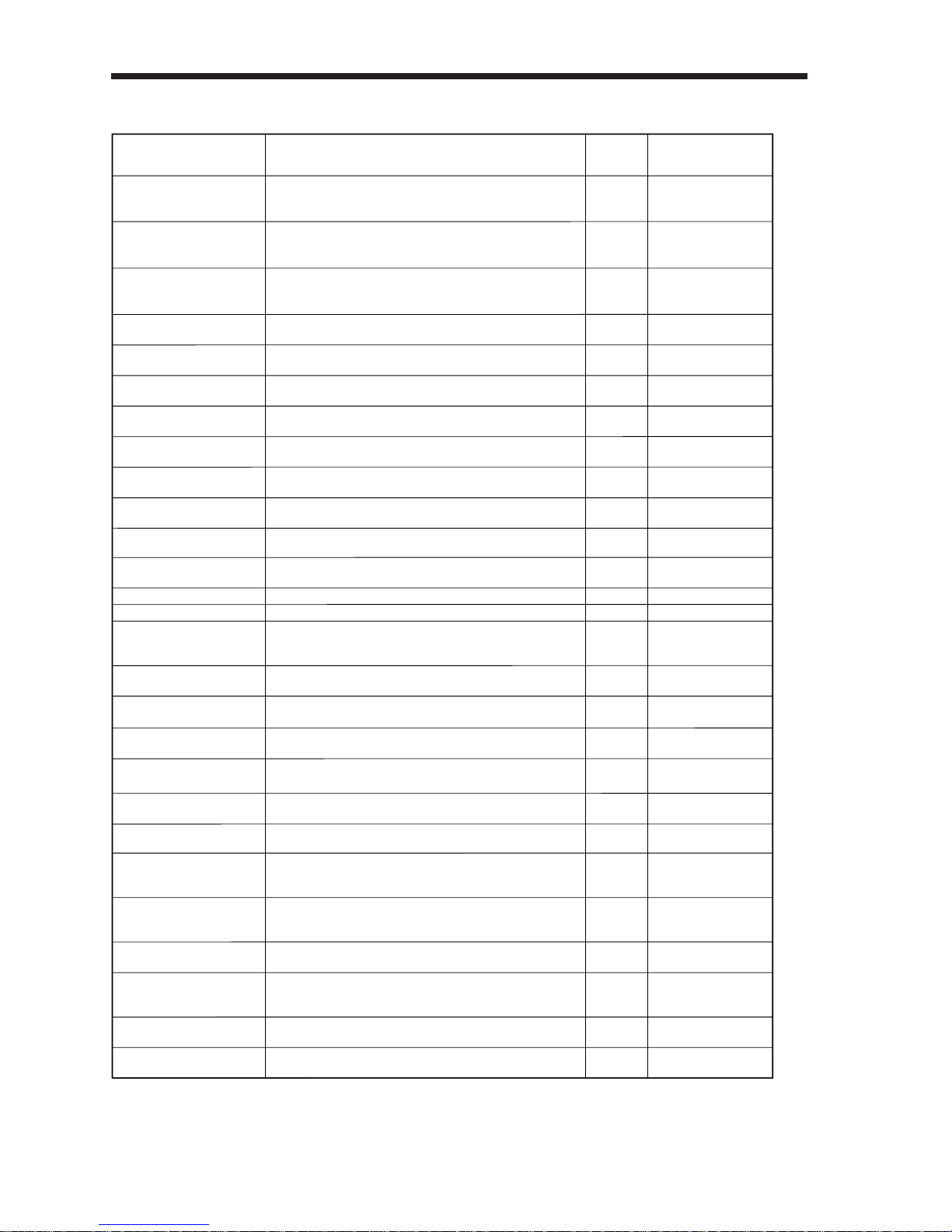
1-3 Function List
Function
Position control mode
Speed control mode
Torque control mode
Description
(Note)
Control Mode
P
S
T
Refer To
Section 2-1-1
Section 2-2-2 (2)
Section 3-1-3 (1)
Section 2-1-2
Section 2-2-2 (3)
Section 3-1-3 (2)
Section 2-1-3
Section 2-2-2 (4)
Section 3-1-3 (3)
Section 3-1-3 (4)
Parameters No. 3, 4
Section 2-4-1
Parameter No. 2
P
P
S
P, S, T
P, S
Note: P: Position control mode, S: Speed control mode, T: Torque control mode
P/S: Position/speed control change mode, S/T: Speed/torque control change mode, T/P: Torque/position
control change mode
MR-J2-A is used as position control servo.
MR-J2-A is used as speed control servo.
MR-J2-A is used as torque control servo.
Electronic gear
Input pulses can be multiplied by 1/50 to 50.
Speed can be increased smoothly in response to input
pulse.
Real-time auto tuning
Smoothing
Servo status is output in terms of voltage in real time.
Analog monitor output
Speed can be increased and decreased smoothly.
S-pattern acceleration/
deceleration time constant
Automatically adjusts the gain to optimum value if load
applied to the servo motor shaft varies.
Position/speed control
change mode
P/S
Using external input signal, control can be switched between position control and speed control.
Section 3-1-3 (5)
Speed/torque control
change mode
S/T
Using external input signal, control can be switched between speed control and torque control.
Section 3-1-3 (6)
Torque/position control
change mode
T/P
Using external input signal, control can be switched between torque control and position control.
Chapter 5
Absolute position detection
system
P
Return to home position is not required at each power on
after it has been made once.
Section 2-4-3
Parameter No. 7
Parameter No. 17
P, S, T
Alarm history is cleared.
Alarm history clear
Parameter No. 16
P
Command pulse train form can be selected from among
four different types.
Command pulse selection
Parameter No. 21
P, S, T
Forward rotation start, reverse rotation start, servo on and
other input signals can be assigned to any pins.
Input signal selection
Parameters No. 43 to
48
P, S
Servo motor-generated torque can be limited to any value.
Torque limit
Section 3-1-3 (1) q
Parameter No. 28
P, S, T
Servo motor can be run from the operation section of the
servo amplifier without the start signal entered.
Test operation mode
Section 2-3-3 (3)
P, S, T
Using a personal computer, parameter setting, test operation, status display, etc. can be performed.
Servo configuration software
Section 6-1-5
P, S, T
If an alarm has occurred, the corresponding alarm number
is output in 3-bit code.
Alarm code output
Section 8-2-1
P, S, T
Used when the built-in regenerative brake resistor of the
servo amplifier does not have sufficient regenerative capability for the regenerative power generated.
Regenerative brake option
Section 6-1-1
Section 3-1-3 (3) e
Parameter No. 8~10
TServo motor speed can be limited to any value.Speed limit
Section 2-3-2
P, S, T
Servo status is shown on the 4-digit, 7-segment LED
display.
Status display
Section 2-3-3 (1)
P, S, T
ON/OFF statuses of external I/O signals are shown on the
display.
External I/O display
Section 2-3-3 (2)
P, S, T
Output signal can be forced on/off independently of the
servo status.
Use this function for output signal wiring check, etc.
Output signal forced output
Section 2-3-3
S, T
Voltage is automatically offset to stop the servo motor
if it does not come to a stop at the analog speed command
(VC) or analog speed limit (VLA) of 0V.
Automatic VC offset
S
If the input power supply voltage had reduced to cause
an alarm but has returned to normal, the servo motor can
be restarted by merely switching on the start signal.
Restart after instantaneous
power failure
Parameter No. 20
Parameter No. 13
Slight vibration suppression
control
P
Suppresses vibration of ±1 pulse produced at a servo
motor stop.
Page 28
1. INTRODUCTION
1
1– 15
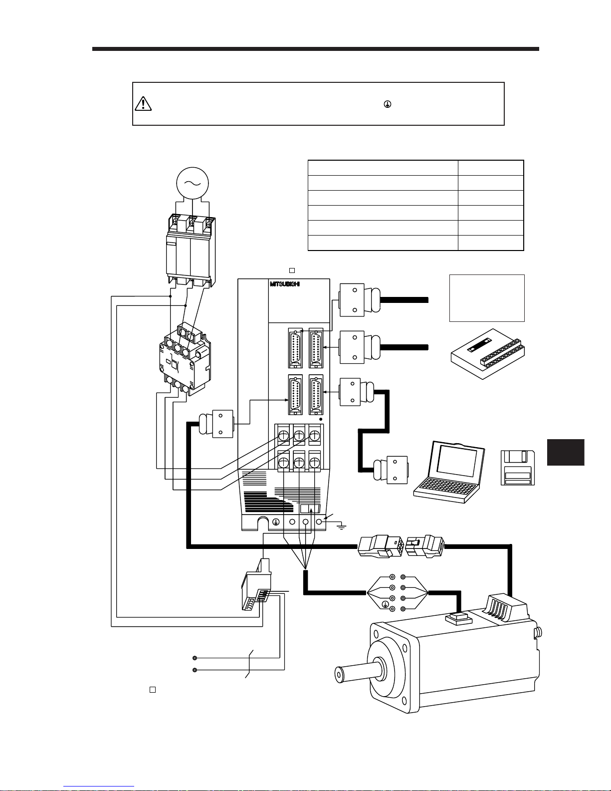
1-4 Basic Configuration
To prevent an electric shock, always connect the protective
earth (PE) terminal (terminal marked ) of the servo amplifier
to the protective earth (PE) of the control box.
WARNING
1-4-1 MR-J2-100A or less
(1) Three-phase 200V or single-phase 230V power supply models
(Note 2)
Power supply
3-phase 200V
or
1-phase 230V
No-fuse breaker
(NFB) or fuse
Magnetic
contactor
(MC)
To CN2
To CN3
To CN1B
To CN1A
L1
L2
L3
L
21
L
11
Protective earth (PE) terminal
(Note 1)
Encoder cable
(Note 1)
Power leads
Servo motor
Junction terminal block
UV
W
Set-up
software
Servo amplifier
MR-J2- A
Regenerative brake option
D
P
C
U
V
W
CHARGE
MR-J2-60A
Options and Auxiliary Equipment
No-fuse breaker
Magnetic contactor
Set-up software
Regenerative brake option
Cables
Refer To
Section 6-2-2
Section 6-2-2
Section 6-1-5
Section 6-1-1
Section 6-2-1
Positioning unit
Control circuit terminal block
Personal
computer
Note: 1. The HA-FF C-UE, HC-SF series have Cannon connectors.
(Refer to Section 3-2-2.)
Note: 2. A single-phase 230V power supply may be used with the servo amplifier of MR-J2-70A or
less. Connect the power supply to L1 and L2 terminals and leave L3 open. Note that this
power supply cannot be used for a combination with the HC-SF52 and 53 servo motor.
Page 29
1. INTRODUCTION
1– 16
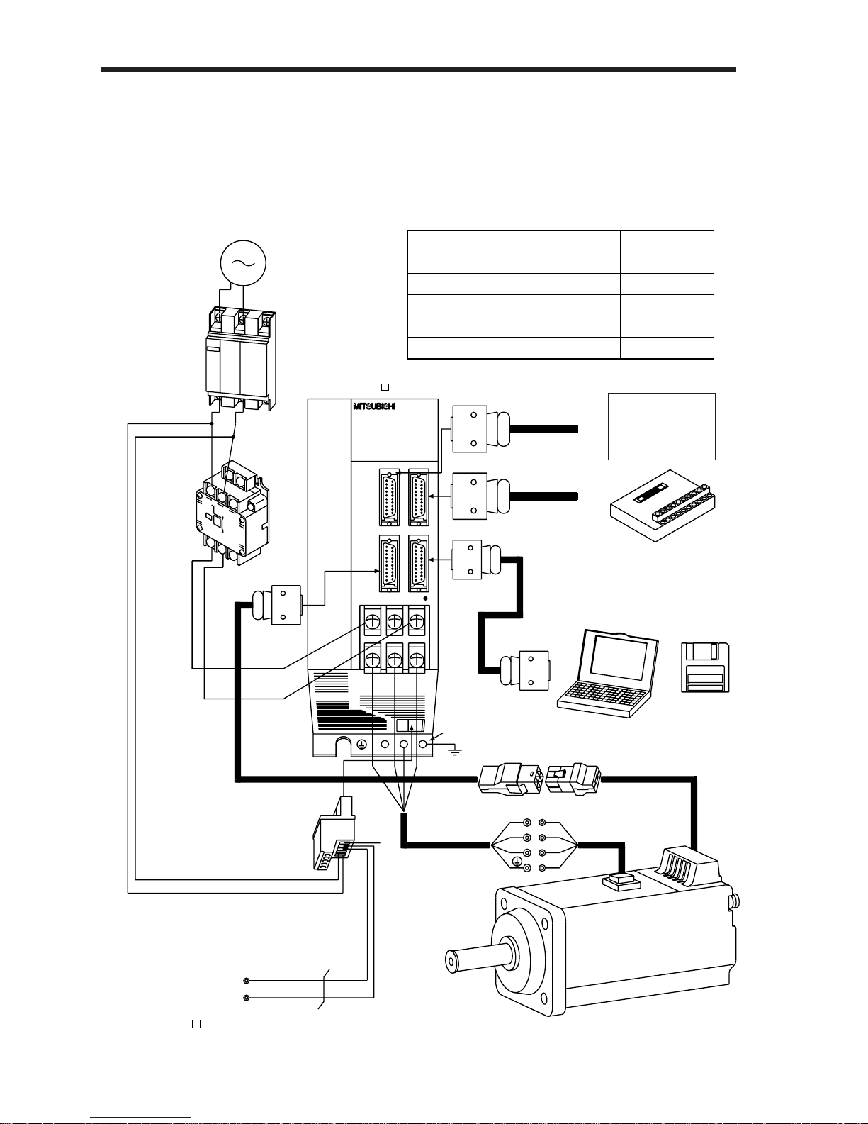
(2) Single-phase 100V power supply model
Note: The HA-FF C-UE series have Cannon connectors.
(Refer to Section 3-2-2.)
1-phase 100V
power supply
No-fuse breaker
(NFB) or fuse
Magnetic
contactor
(MC)
To CN2
To CN3
To CN1B
To CN1A
L1
L2
L
21
L
11
Protective earth (PE) terminal
(Note)
Encoder cable
(Note)
Power leads
Servo motor
Junction terminal block
UV
W
Set-up
software
Servo amplifier
MR-J2- A1
Regenerative brake option
D
P
C
U
V
W
CHARGE
MR-J2-60A
Options and Auxiliary Equipment
No-fuse breaker
Magnetic contactor
Set-up software
Regenerative brake option
Cables
Refer To
Section 6-2-2
Section 6-2-2
Section 6-1-5
Section 6-1-1
Section 6-2-1
Positioning unit
Control circuit terminal block
Personal
computer
Page 30
1. INTRODUCTION
1
1– 17
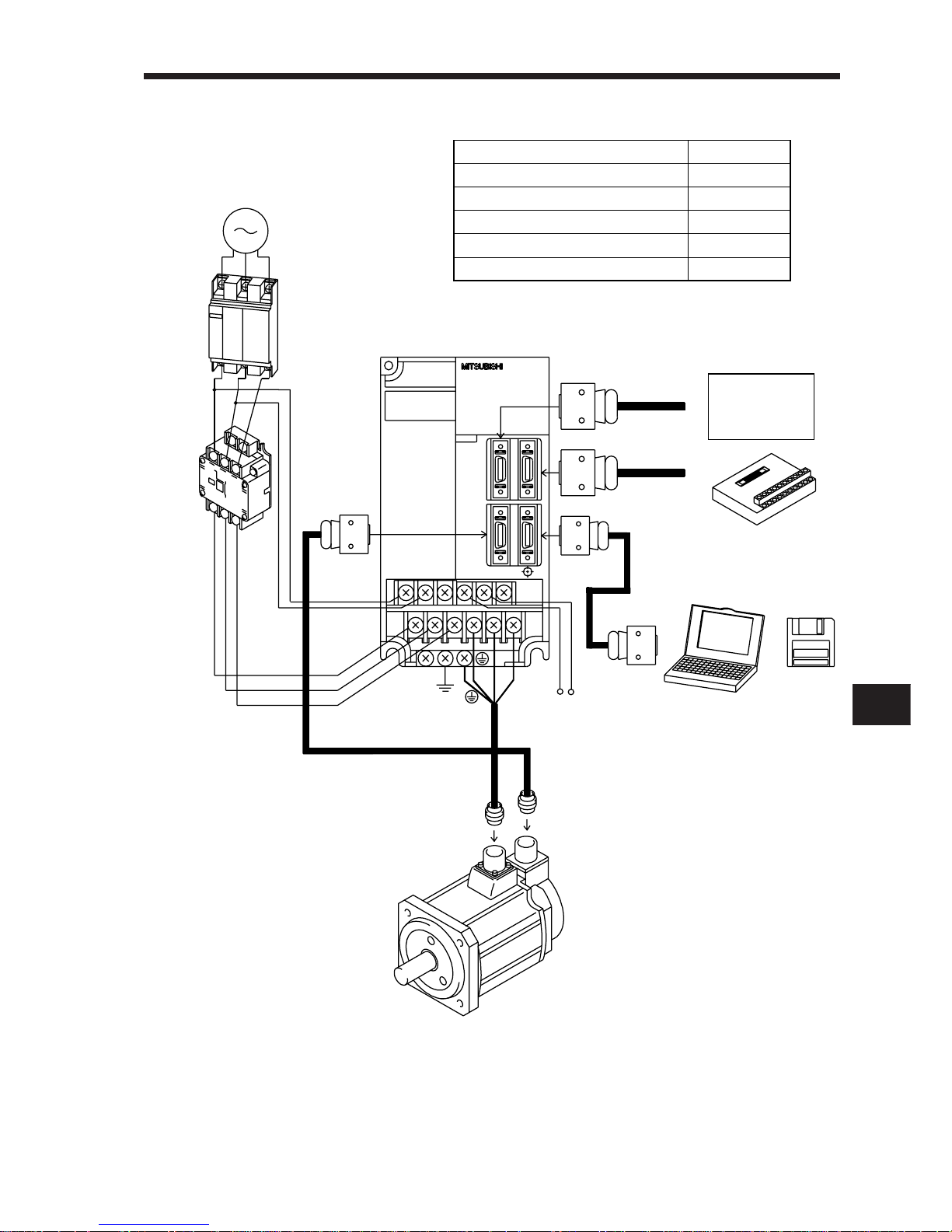
1-4-2 MR-J2-200A or more
3-phase 200V
power supply
No-fuse breaker
(NFB) or fuse
Magnetic
contactor
(MC)
To CN2
To CN3
To CN1B
To CN1A
Junction terminal block
Set-up
software
Regenerative brake option
Options and Auxiliary Equipment
No-fuse breaker
Magnetic contactor
Set-up software
Regenerative brake option
Cables
Refer To
Section 6-2-2
Section 6-2-2
Section 6-1-5
Section 6-1-1
Section 6-2-1
Positioning unit
Personal
computer
L1
L2
L3
L11
L21
U
V
W
PC
Servo amplifier
Page 31
CHAPTER 2
CHAPTER 3
CHAPTER 4
CHAPTER 5
CHAPTER 6
CHAPTER 7
CHAPTER 8
CHAPTER 9
CHAPTER 10
CHAPTER 11
CHAPTER 2
OPERATION
2 – 1
This chapter gives basic connection examples and operation procedures.
CHAPTER 1
INTRODUCTION
OPERATION
WIRING
INSTALLATION
ABSOLUTE POSITION DETECTION SYSTEM
OPTIONS AND AUXILIARY EQUIPMENT
INSPECTION
TROUBLESHOOTING
CHARACTERISTICS
SPECIFICATIONS
SELECTION
2-1 Standard Connection Examples
2-1-1 Position control mode
2-1-2 Speed control mode
2-1-3 Torque control mode
2-2 Operation
2-2-1 Pre-operation checks
2-2-2 Start-up
2-3 Display and Operation
2-3-1 Display flowchart
2-3-2 Status display
2-3-3 Diagnostic mode
2-3-4 Alarm mode
2-3-5 Parameter mode
2-4 Adjustments
2-4-1 Auto tuning
2-4-2 Manual gain adjustment
2-4-3 Slight vibration suppression control
Page 32
2. OPERATION
2– 2
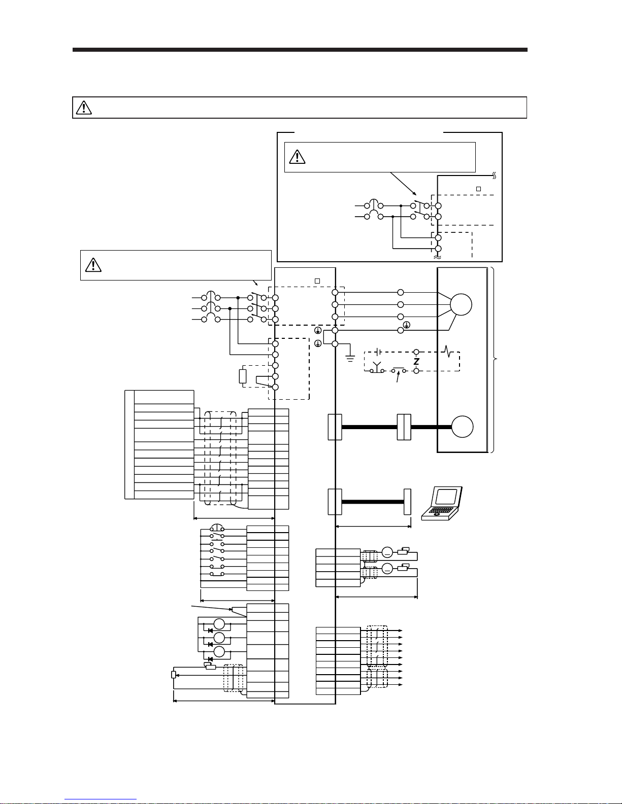
2-1 Standard Connection Examples
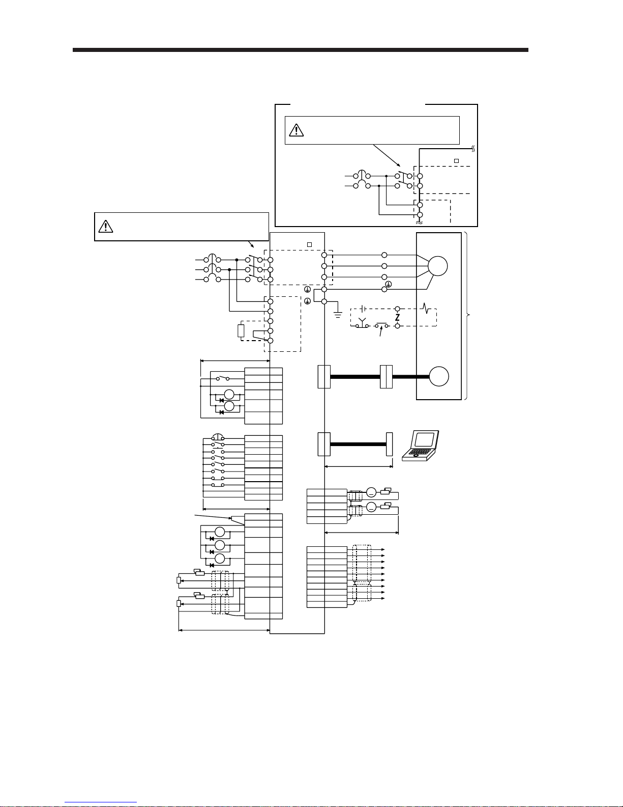
2-1-1 Position control mode
(1) Connection with the FX-1GM
Always follow the instructions in Chapter 3.
CAUTION
MC
NFB
Servo amplifier
MR – J2 – A
TE1
U
U
(Red)
V
(White)
W
(Black)
(Green)
(Note 1)
V
W
L1
L2
L3
L11
L21
C
D
P
TE2
Make up a sequence which
switches off the MC at alarm
occurrence or emergency stop.
CN1A(Note 5, 8)
CN1B(Note 5, 8)
(Note 5, 8, 10)
CN3
(Note 5, 8, 10)
CN3
(Note 5, 8)
CN2
CN1B(Note 5, 8)
OPC
24+
Signal
COM1
SVRDY
SV END
COM2
PG0
COM5
CLR
FP
COM4
RP
COM
RD
INP
P15R
OP
SG
CR
PP
SG
NP
SD
11
9
19
18
4
14
10
8
3
20
2
EMG
15
SON
5
RES
PC
14
TL
8
LSP
9
LSN
16
SG
17
20
SG
3
VDD
MO1
4
LG
3
MO2
14
LG
13
SD
Plate
13
COM
18
ALM
RA1
RA2
RA3
19
ZSP
6
TLC
11
P15R
12
TLA
1
LG
Plate
SD
10
Plate
Positioning unit FX-1GM
2m (6.5ft) or less
10m (32ft) or less
Do not connect when external
power supply is used.
(Note 2, 6)
(Note 9) Trouble
Zero speed
Limiting torque
Upper limit setting
Analog torque limit
±10V/max. current
2m (6.5ft) or less
2m (6.5ft) or less
15m (49ft) or less
10kΩ
10kΩ
A
A
Monitor output
Max. +1mA meter
Reading in both directions
Communication cable
(Option)
Encoder cable
(Option)
Personal computer
+
Windows 3.1
Encoder
EMG
B2
B1
24VDC
To be shut off when servo-on
signal switches off or alarm
signal is given.
SM
Electromagnetic
brake
Servo motor
CAUTION
Power supply
3-phase 200VAC
or
(Note 13) 1-phase 230VAC
(Note 4)
Regenerative
brake option
(Note 11)
(Note 3, 7) External emergency stop
Servo on
Reset
Proportion control
Torque limit
(Note 7) Forward rotation stroke end
Reverse rotation stroke end
MC
NFB
Servo amplifier
MR – J2 – A1
TE1
L1
L2
L11
L21
Power supply
Single-phase 100VAC
For single-phase 100V power supply
5LZ
Encoder Z-phase pulse (differential line driver)
Encoder A-phase pulse (differential line driver)
Encoder B-phase pulse (differential line driver)
Control common
Encoder Z-phase pulse (open collector)
15 LZR
6LA
16 LAR
7LB
17 LBR
1LG
14 OP
4 P15R
Plate
SD
(Note 5, 8)
CN1A
Make up a sequence which
switches off the MC at alarm
occurrence or emergency stop.
CAUTION
(Note 12)
Page 33
2
2. OPERATION
2– 3
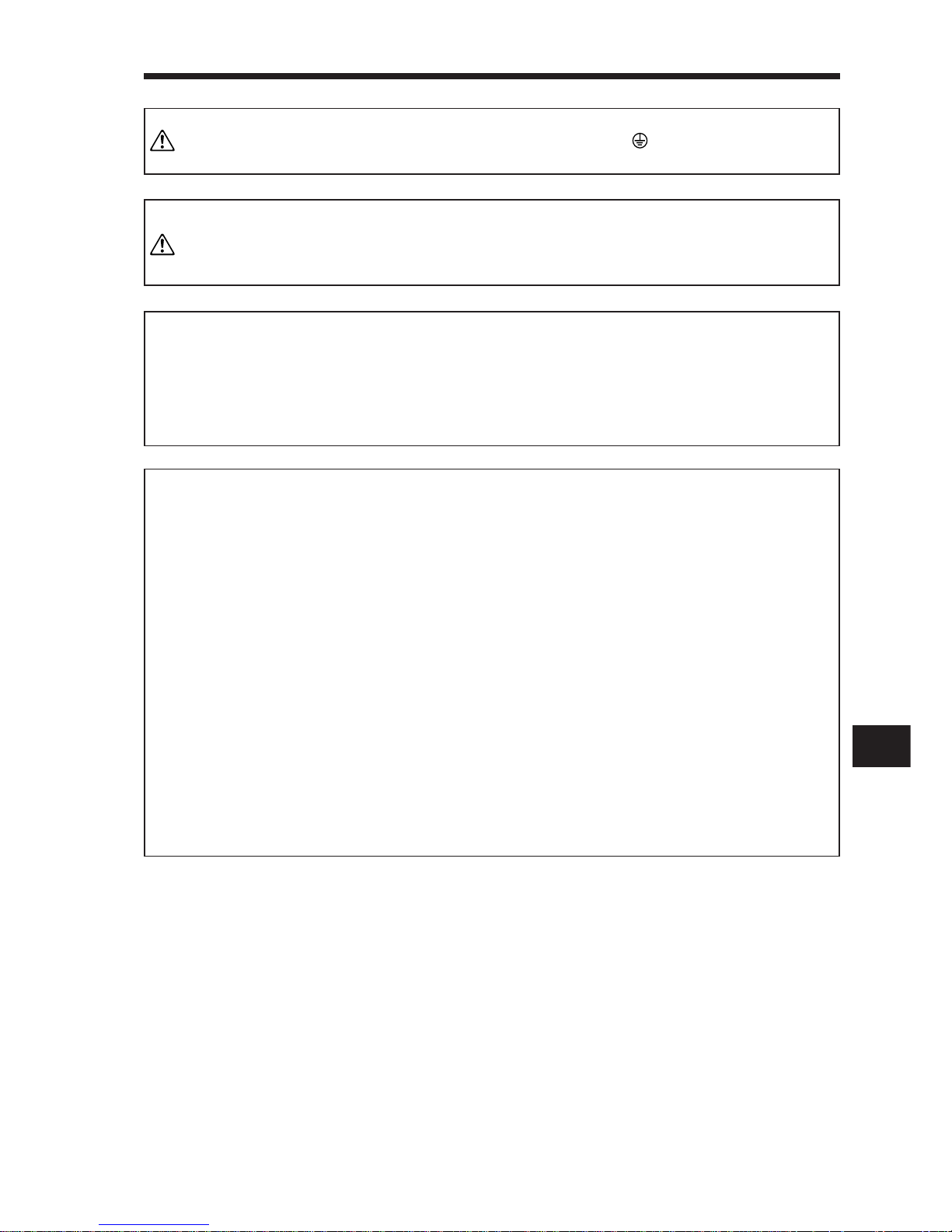
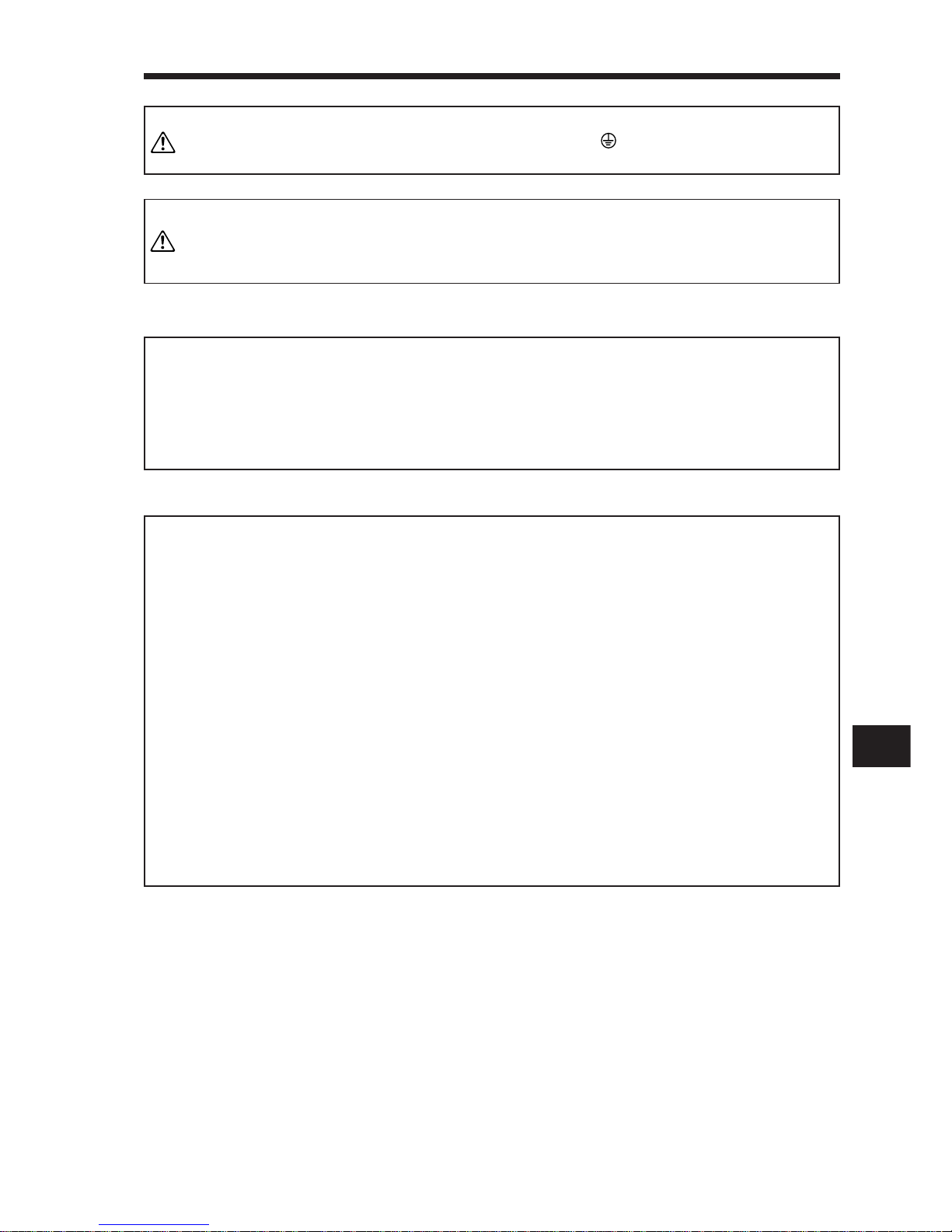
Note: 7. When starting operation, always connect the external emergency
stop signal (EMG) and forward/reverse rotation stroke end signal
(LSN/LSP) with SG. (Normally closed contacts)
8. The pins with the same signal name are connected in the servo
amplifier.
9. The trouble (ALM) signal is on when there is no alarm, i.e. in the
normal state.
When this signal is switched off (at occurrence of an alarm), the
output of the controller should be stopped by the sequence program.
10. When connecting the personal computer together with monitor
outputs 1, 2, use the maintenance junction card (MR-J2CN3TM).
11. This length applies to the command pulse train input in the
opencollector system. It is 10m (32 ft) or less in the differential
line driver system.
12. The connection method changes with the servo motor series.
Refer to Section 3-2-2.
13. A single-phase 230V power supply may be used with the servo
amplifier of MR-J2-70A or less. Connect the power supply to L1
and L2 terminals and leave L3 open. Note that this power supply
cannot be used for a combination with the HC-SF52 servo motor.
Note: 2. Connect the diode in the correct direction. If it is connected re-
versely, the servo amplifier will be faulty and will not output signals, disabling the emergency stop and other protective circuits.
3. The emergency stop switch must be installed.
Note: 1. To prevent an electric shock, always connect the protective
earth(PE) terminal (terminal marked ) of the servo amplifier to
the protective earth (PE) of the control box.
Note: 4. When using the regenerative brake option, always remove the
lead from across D-P.
5. CN1A, CN1B, CN2 and CN3 have the same shape. Wrong connection of the connectors will lead to a fault.
6. The sum of currents that flow in the external relays should be
80mA max. If it exceeds 80mA, supply interface power from external.
WARNING
NOTICE
CAUTION
MEMORANDUM
Page 34
2. OPERATION
2– 4
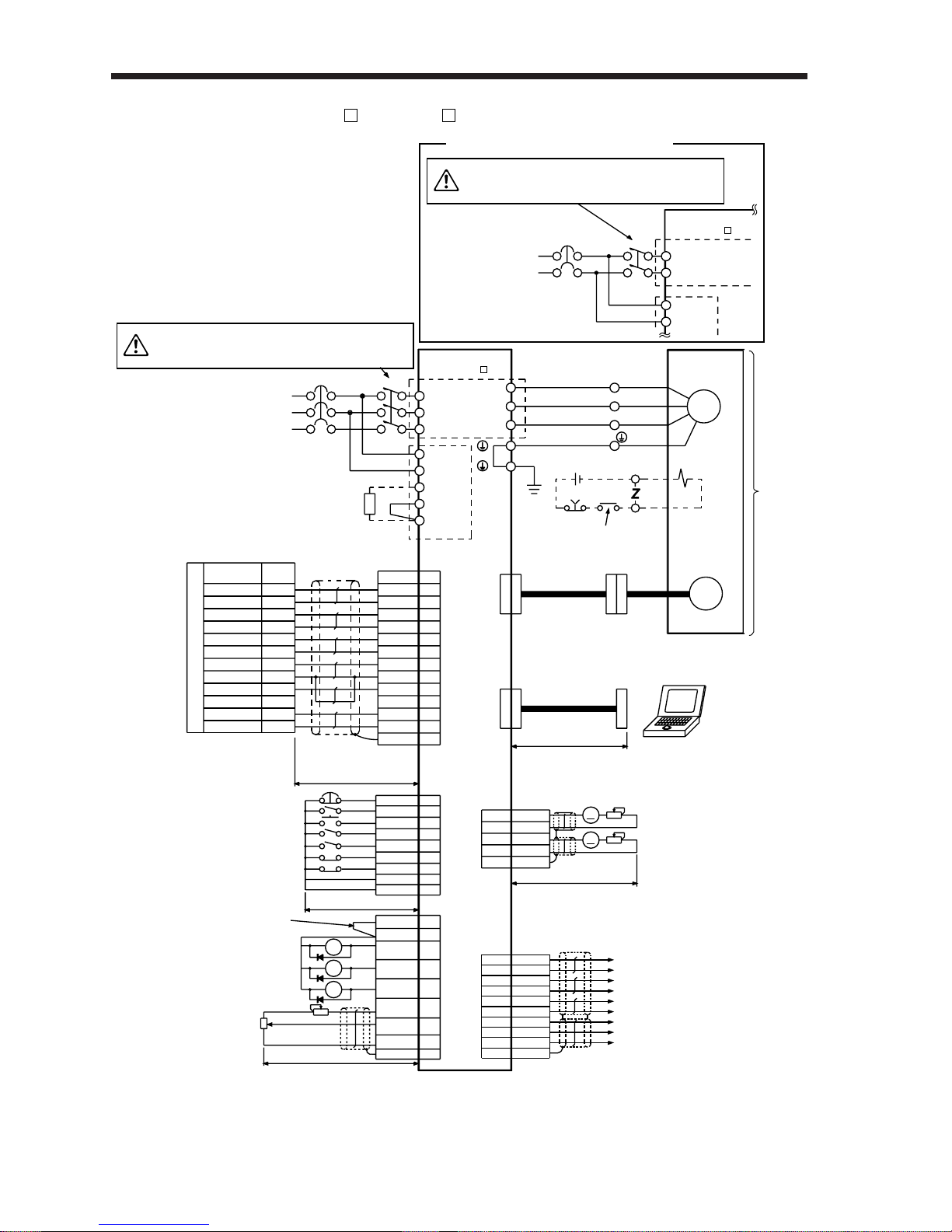
(2) Connection with the AD75P /A1SD75P
MC
NFB
Servo amplifier
MR – J2 – A
TE1
U
V
W
L1
L2
L3
L11
L21
C
D
P
TE2
Power supply
3-phase 200VAC
or
(Note 13) 1-phase 230VAC
Signal
Pin No.
OPC
PP
PULSE F+
3
PULSE F -
21
PULSE R+
4
PULSE R -
22
CLEAR
5
CLEAR COM
23
READY
7
COM
26
INPS
8
PG0(+5V)
24
PG0 COM
25
PG
13
NP
2
NG
12
CR
8
SG
10
RD
COM
19
9
INP
18
LZ
5
LZR
15
EMG
15
SON
5
RES
14
PC
8
TL
9
LSP
16
LSN
17
SG
10
SG
20
11
3
SD
Plate
10m (32ft) or less
Positioning unit AD75P/AISD75P
3
VDD
13
COM
18
ALM
19
ZSP
6
TLC
11
P15R
12
TLA
1
LG
Plate
SD
10m (32ft) or less
RA1
RA2
RA3
Do not connect when external
power supply is used.
(Note 2, 6)
(Note 9) Trouble
Zero speed
Limiting torque
Upper limit setting
Analog torque limit
±10V/max. current
2m (6.5ft) or less
2m (6.5ft) or less
MO1
4
LG
3
MO2
14
LG
13
SD
Plate
15m (49ft) or less
10kΩ
10kΩ
A
A
Monitor output
Max. +1mA meter
Reading in both directions
Communication cable
(Option)
Encoder cable
(Option)
Personal computer
+
Windows 3.1
Encoder
EMG
B2
B1
24VDC
To be shut off when servo-on
signal switches off or alarm
signal is given.
Electromagnetic
brake
U
(Red)
V
(White)
W
(Black)
(Green)
SM
Servo motor
(Note 1)
(Note 4)
Regenerative
brake option
CN1A(Note 5, 8)
CN1B(Note 5, 8)
CN1B(Note 5, 8)
(Note 5, 8, 10)
CN3
(Note 5, 8, 10)
CN3
(Note 5, 8)
CN2
(Note 11)
Make up a sequence which
switches off the MC at alarm
occurrence or emergency stop.
CAUTION
(Note 3, 7) External emergency stop
Servo on
Reset
Proportion control
Torque limit
(Note 7) Forward rotation stroke end
Reverse rotation stroke end
MC
NFB
Servo amplifier
MR – J2 – A1
TE1
L1
L2
L11
L21
Power supply
Single-phase 100VAC
For single-phase 100V power supply
(Note 12)
5LZ
Encoder Z-phase pulse (differential line driver)
Encoder A-phase pulse (differential line driver)
Encoder B-phase pulse (differential line driver)
Control common
Encoder Z-phase pulse (open collector)
15 LZR
6LA
16 LAR
7LB
17 LBR
1LG
14 OP
4 P15R
Plate
SD
(Note 5, 8)
CN1A
Make up a sequence which
switches off the MC at alarm
occurrence or emergency stop.
CAUTION
Page 35
2
2. OPERATION
2– 5
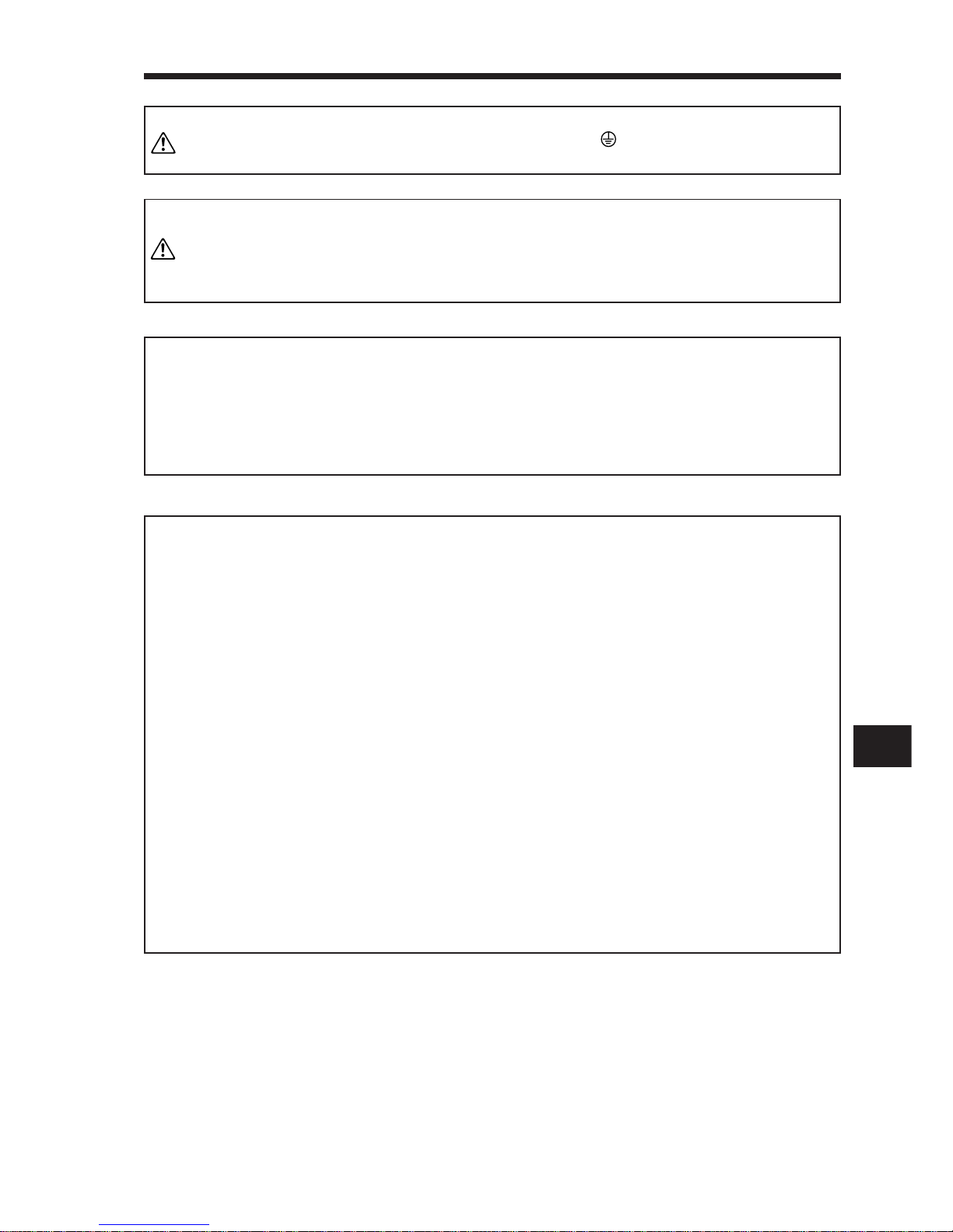
Note: 7. When starting operation, always connect the external emergency
stop signal (EMG) and forward/reverse rotation stroke end signal
(LSN/LSP) with SG. (Normally closed contacts)
8. The pins with the same signal name are connected in the servo
amplifier.
9. The trouble (ALM) signal is on when there is no alarm, i.e. in the
normal state.
When this signal is switched off (at occurrence of an alarm), the
output of the controller should be stopped by the sequence
program.
10. When connecting the personal computer together with monitor
outputs 1, 2, use the maintenance junction card (MR-J2CN3TM).
11. This length applies to the command pulse train input in the
differential line driver system. Though the command pulse train
input may be in the open collector system, we recommend the
differential line driver system which is less affected by external
noises. The length is 2m (6.5ft) or less in the open collector
system.
12. The connection method changes with the servo motor series.
Refer to Section 3-2-2.
13. A single-phase 230V power supply may be used with the servo
amplifier of MR-J2-70A or less. Connect the power supply to L1
and L2 terminals and leave L3 open. Note that this power supply
cannot be used for a combination with the HC-SF52 servo motor.
Note: 1. To prevent an electric shock, always connect the protective earth
(PE) terminal (terminal marked ) of the servo amplifier to the
protective earth (PE) of the control box.
Note: 4. When using the regenerative brake option, always remove the
lead from across D-P.
5. CN1A, CN1B, CN2 and CN3 have the same shape. Wrong
connection of the connectors will lead to a fault.
6. The sum of currents that flow in the external relays should be
80mA max. If it exceeds 80mA, supply interface power from
external.
Note: 2. Connect the diode in the correct direction. If it is connected
reversely, the servo amplifier will be faulty and will not output
signals, disabling the emergency stop and other protective circuits.
3. The emergency stop switch must be installed.
CAUTION
WARNING
NOTICE
MEMORANDUM
Page 36
2. OPERATION
2– 6
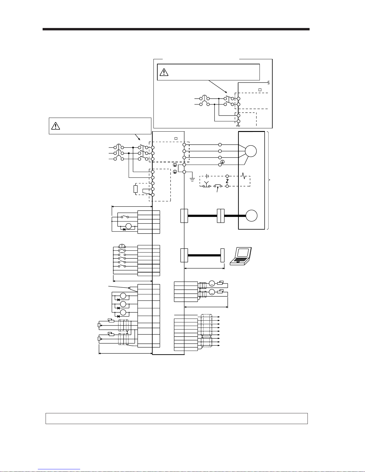
2-1-2 Speed control mode
Servo amplifier
MR – J2 – A
TE1
L1
L11
L21
C TE2
D
P
NFB
Power supply
3-phase 200VAC
or
(Note) 1-phase 230VAC
MC
L2
L3
U
V
W
COM 9
SP1 8
10
SG
RD 19
SA 18
SG 20
10m (32ft) or less
Speed selection 1
Ready
Speed reached
EMG 15
SON 5
RES 14
SP2 7
ST1 8
ST2 9
LSP 16
LSN 17
SG 10
SG 20
10m (32ft) or less
(Note 2, 6)
VDD 3
5LZ
4 MO1
3LG
14 MO2
13 LG
Plate
SD
Encoder Z-phase pulse (differential line driver)
Monitor output
Max. +1mA meter
Reading in both directions
Encoder A-phase pulse (differential line driver)
Encoder B-phase pulse (differential line driver)
Control common
Encoder Z-phase pulse (open collector)
15 LZR
6LA
16 LAR
7LB
17 LBR
1LG
14 OP
4 P15R
Plate
SD
COM 13
ALM 18
ZSP 19
TLC 6
P15R 11
VC 2
TLA 12
LG 1
SD Plate
2m (6.5ft) or less
(Note 9) Trouble
Zero speed
(Note 7) Limiting torque
Do not connect when external
power supply is used.
RA1
RA2
RA3
Servo motor
Electromagnetic
brake
U(Red)
V(White)
W(Black)
(Green)
SM
B1
24VDC
EMG
B2
Encoder cable
(Option)
Communication cable
(Option)
15m (49ft) or less
10kΩ
10kΩ
Personal computer
+
Windows 3.1
A
A
2m (6.5ft) or less
To be shut off when servo-on
signal switches off or alarm
signal is given.
RA4
RA5
(Note 1)
(Note 4)
Regenerative
brake option
(Note 5, 8)
CN1A
CN1B
(Note 5, 8)
CN1B(Note 5, 8)
(Note 5, 8)
CN1A
(Note 5, 8, 10)
CN3
(Note 5, 8, 10)
CN3
(Note 5, 8)
CN2
Upper limit setting
Upper limit setting
Analog speed command
±10V/max. current
±10V/max. current
(Note 11) Analog command limit
Encoder
Make up a sequence which
switches off the MC at alarm
occurrence or emergency stop.
CAUTION
(Note 3, 7) External emergency stop
Servo on
Reset
Speed selection 2
Forward rotation start
Reverse rotation start
(Note 7) Forward rotation stroke end
Reverse rotation stroke end
MC
NFB
Servo amplifier
MR – J2 – A1
TE1
L1
L2
L11
L21
Power supply
Single-phase 100VAC
For single-phase 100V power supply
(Note 12)
Make up a sequence which
switches off the MC at alarm
occurrence or emergency stop.
CAUTION
Page 37
2
2. OPERATION
2– 7
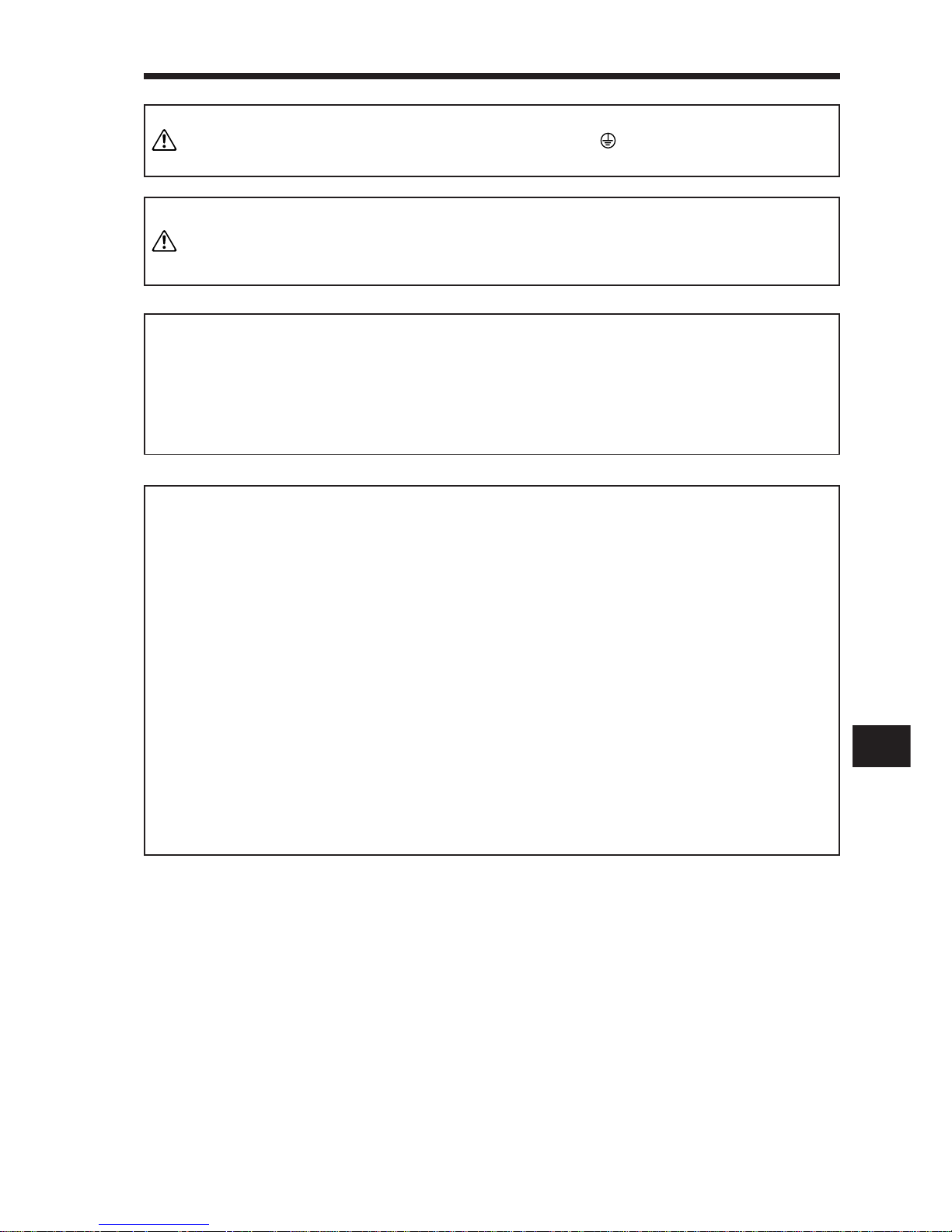
Note: 2. Connect the diode in the correct direction. If it is connected re-
versely, the servo amplifier will be faulty and will not output signals, disabling the emergency stop and other protective circuits.
3. The emergency stop switch must be installed.
Note: 4. When using the regenerative brake option, always remove the
lead from across D-P.
5. CN1A, CN1B, CN2 and CN3 have the same shape. Wrong connection of the connectors will lead to a fault.
6. The sum of currents that flow in the external relays should be
80mA max. If it exceeds 80mA, supply interface power from external.
Note: 1. To prevent an electric shock, always connect the protective earth
(PE) terminal (terminal marked ) of the servo amplifier to the
protective earth (PE) of the control box.
Note: 7. When starting operation, always connect the external emergency
stop signal (EMG) and forward/reverse rotation stroke end signal
(LSN/LSP) with SG. (Normally closed contacts)
8. The pins with the same signal name are connected in the servo
amplifier.
9. The trouble (ALM) signal is on when there is no alarm, i.e. in the
normal state.
When this signal is switched off (at occurrence of an alarm), the
output of the controller should be stopped by the sequence program.
10. When connecting the personal computer together with monitor
outputs 1, 2, use the maintenance junction card (MR-J2CN3TM).
11. TLA can be used by setting any of parameters No. 43 to 48 to
make TL available.
12. The connection method changes with the servo motor series.
Refer to Section 3-2-2.
13. A single-phase 230V power supply may be used with the servo
amplifier of MR-J2-70A or less. Connect the power supply to L1
and L2 terminals and leave L3 open. Note that this power supply
cannot be used for a combination with the HC-SF52 servo motor.
WARNING
CAUTION
NOTICE
MEMORANDUM
Page 38
2. OPERATION
2– 8
2-1-3 Torque control mode
For notes, refer to page 2-6.
Servo amplifier
MR – J2 – A
TE1
L1
L11
L21
C TE2
D
P
NFB
Power supply
3-phase 200VAC
or
(Note 12) 1-phase 230VAC
(Note 4)
Regenerative
brake option
MC
L2
L3
U
V
W
(Note 5, 8)
CN1A
(Note 5, 8)
CN2
COM 9
SP1 8
10
SG
RD 19
SG 20
10m (32ft) or less
Speed selection 1
Ready
CN1B
(Note 5, 8)
(Note 5, 8, 10)
CN3
EMG 15
SON 5
RES 14
SP2 7
RS1 9
RS2 8
SG 10
SG 20
(Note 3, 7) External emergency stop
Servo on
Reset
Speed selection 2
Forward rotation selection
Reverse rotation selection
10m (32ft) or less
CN1B(Note 5, 8)
(Note 2, 6)
VDD 3
COM 13
ALM 18
ZSP 19
VLC 6
P15R 11
TC 12
LG 1
VLA 2
SD
Plate
2m (6.5ft) or less
(Note 9) Trouble
Zero speed
Upper limit setting
Upper limit setting
Analog torque command
±8V/max. current
Analog speed command
0 to +10V/max. current
Limiting speed
Do not connect when external
power supply is used.
RA1
RA2
RA3
5LZ
Encoder Z-phase pulse (differential line driver)
Encoder A-phase pulse (differential line driver)
Encoder B-phase pulse (differential line driver)
Control common
Encoder Z-phase pulse (open collector)
15 LZR
6LA
16 LAR
7LB
17 LBR
1LG
14 OP
4 P15R
Plate
SD
4 MO1
3LG
14 MO2
13 LG
Plate
SD
Monitor output
Max. +1mA meter
Reading in both directions
10kΩ
10kΩ
A
A
2m (6.5ft) or less
(Note 5, 8, 10)
CN3
(Note 5, 8)
CN1A
Communication cable
(Option)
15m (49ft) or less
Personal computer
+
Windows 3.1
Electromagnetic
brake
B1
24VDC
EMG
B2
Encoder cable
(Option)
Encoder
U(Red)
V(White)
W(Black)
(Green)
(Note 1)
Servo motor
SM
To be shut off when servo-on
signal switches off or alarm
signal is given.
RA4
Make up a sequence which
switches off the MC at alarm
occurrence or emergency stop.
CAUTION
MC
NFB
Servo amplifier
MR – J2 – A1
TE1
L1
L2
L11
L21
Power supply
Single-phase 100VAC
For single-phase 100V power supply
(Note 11)
Make up a sequence which
switches off the MC at alarm
occurrence or emergency stop.
CAUTION
Page 39
2
2. OPERATION
2– 9
Note: 1. To prevent an electric shock, always connect the protective earth
(PE) terminal (terminal marked ) of the servo amplifier to the
protective earth (PE) of the control box.
Note: 2. Connect the diode in the correct direction. If it is connected re-
versely, the servo amplifier will be faulty and will not output signals, disabling the emergency stop and other protective circuits.
3. The emergency stop switch must be installed.
Note: 4. When using the regenerative brake option, always remove the
lead from across D-P.
5. CN1A, CN1B, CN2 and CN3 have the same shape. Wrong connection of the connectors will ead to a fault.
6. The sum of currents that flow in the external relays should be
80mA max. If it exceeds 80mA, supply interface power from external.
Note: 7. When starting operation, always connect the external emer-
gency stop signal (EMG) with SG. (Normally closed contacts)
8. The pins with the same signal name are connected in the servo
amplifier.
9. The trouble (ALM) signal is on when there is no alarm, i.e. in
the normal state.
When this signal is switched off (at occurrence of an alarm),
the output of the controller should be stopped by the sequence
program.
10. When connecting the personal computer together with monitor
outputs 1, 2, use the maintenance junction card (MRJ2CN3TM).
11. The connection method changes with the servo motor series.
Refer to Section 3-2-2.
12. A single-phase 230V power supply may be used with the servo
amplifier of MR-J2-70A or less. Connect the power supply to L1
and L2 terminals and leave L3 open. Note that this power
supply cannot be used for a combination with the HC-SF52
servo motor.
WARNING
CAUTION
NOTICE
MEMORANDUM
Page 40
2. OPERATION
2– 10
2-2 Operation
2-2-1 Pre-operation checks
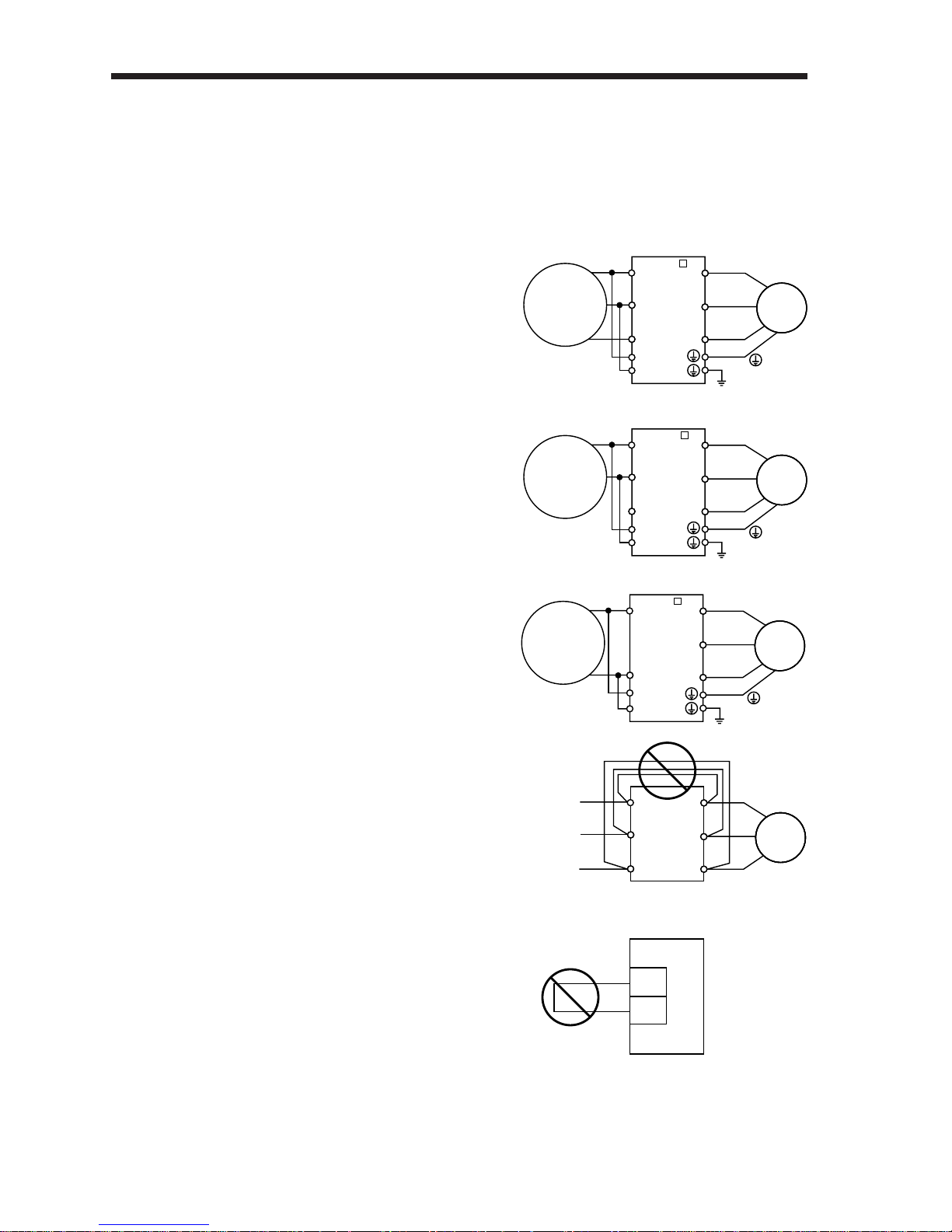
Before starting operation, check the following:
(1) Wiring
1) A correct power supply is connected to the power
input terminals (three-phase 200V: L1, L2, L3;
single-phase 230V: L1, L2; single-phase 100V: L1,
L2) of the servo amplifier.
2) The servo motor power supply terminals (U, V, W)
of the servo amplifier match in phase with the
power input terminals (U, V, W) of the servo motor.
3) The servo motor power supply terminals (U, V, W)
of the servo amplifier are not shorted to the power
input terminals (L1, L2, L3).
4) The servo amplifier and servo motor are grounded
securely.
5) When the regenerative brake option is used, the
lead has been removed across D-P of the control
circuit terminal block. Also, twisted cables are used
for its wiring.
6) When stroke end limit switches are used, the signals across LSP-SG and LSN-SG are on during operation.
7) 24VDC or higher voltages are not applied to the
pins of connectors CN1A and CN1B.
8) SD and SG of connectors CN1A and CN1B are not
shorted.
9) The wiring cables are free from excessive force.
(2) Environment
Signal cables and power cables are not shorted by
wire offcuts,metallic dust or the like.
(3) Machine
1) The screws in the servo motor installation part and
shaft-to-machine connection are tight.
2) The servo motor and the machine connected with
the servo motor can be operated.
Single-phase
100 to 120V
50/60Hz
MR – J2 A1
L
1
Servo amplifier
U
V
W
U
V
W
Servo
motor
SM
L
2
L
11
L
21
Single-phase
230V
50/60Hz
L
1
Servo amplifier
U
V
W
U
V
W
Servo
motor
SM
L
2
L3
L11
L21
MR – J2 A
Three-phase
200 to 230V
50/60Hz
L
1
Servo amplifier
U
V
W
U
V
W
Servo
motor
SM
L
2
L3
L11
L21
MR – J2 A
Servo amplifier
U
V
Servo
motor
SM
W
L
1
L
2
L
3
SD
SG
Servo amplifier
Page 41
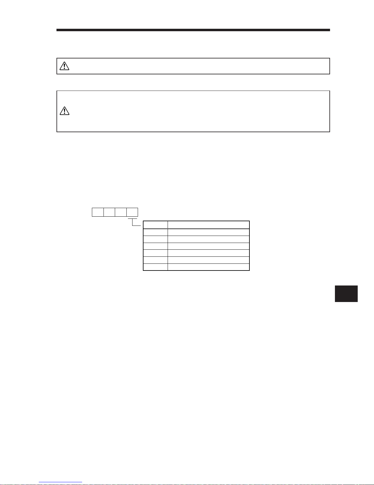
2
2. OPERATION
2– 11
Do not operate the switches with wet hands. You may get an electric shock.
2-2-2 Start-up
1. Before starting operation, check the parameters. Some machines may
perform unexpected operation.
2. During power-on or soon after power-off, do not touch the servo ampli-
fier heat sink, regenerative brake resistor, servo motor, etc. as they
may be at high temperatures. You may get burnt.
(1) Selection of control mode
With parameter No. 0, select the control mode to be used. This parameter is made valid by
setting it and switching power off once, then on again.
WARNING
CAUTION
Set Value
0
1
2
3
4
5
Control Mode
Position control mode
Position/speed control change mode
Speed control mode
Speed/torque control change mode
Torque control mode
Torque/position control change mode
Parameter No. 0
Page 42
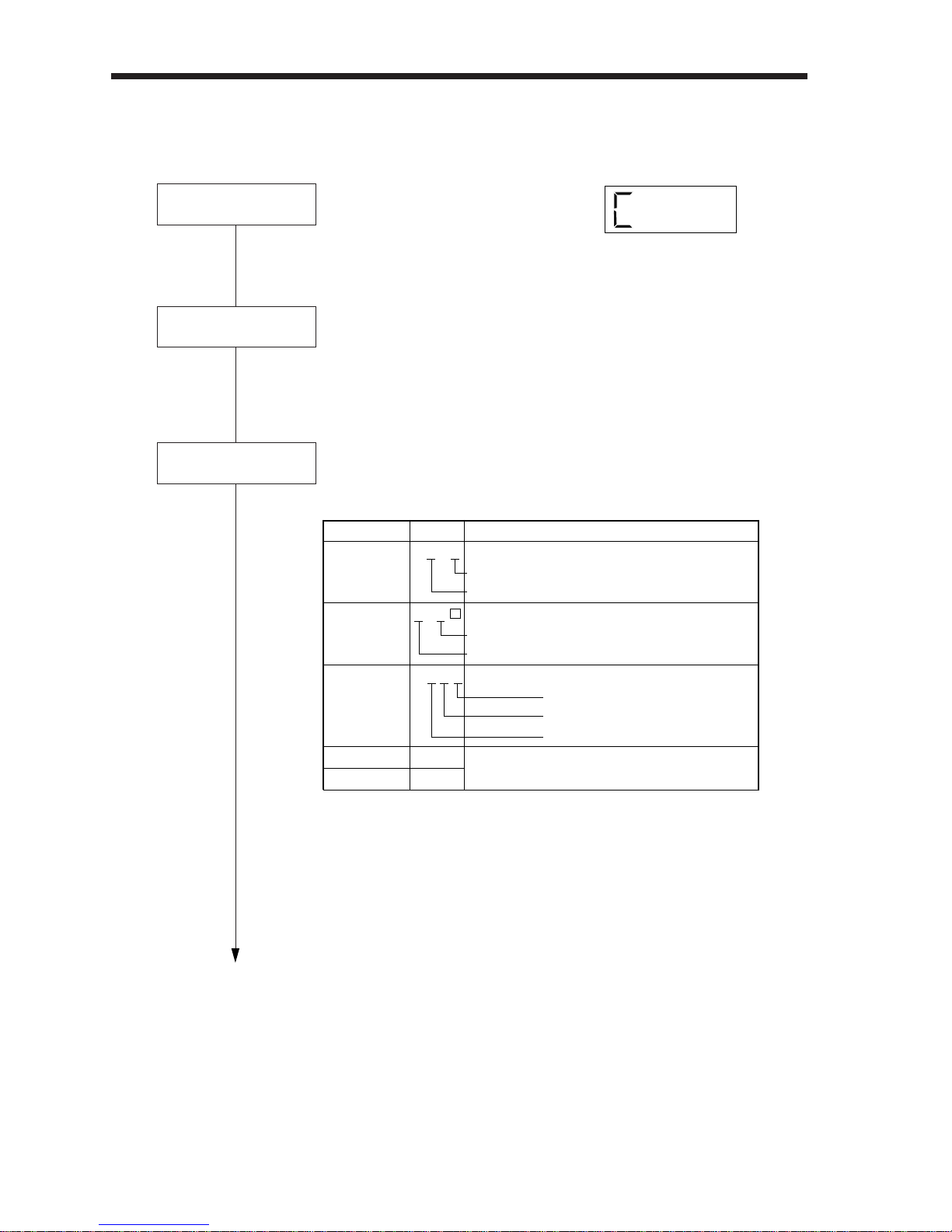
2. OPERATION
2– 12
Parameter setting
Test operation
Power on
1) Switch off the servo-on signal
(SON).
2) When power (NFB) is switched on,
the display shows C (cumulative
feedback pulses).
In the test operation mode, make sure that the servomotor runs.
(Refer to (3) in Section 2-3-3.)
(2) Position control mode
Disconnect the servo motor from the machine, make sure that it operates properly , and reconnect it with the machine.
Set the required parameters. (Refer to Section 2-3-5.)
The servo amplifier and servo motor need not be set in parameters
as they are set automatically.
• Setting example
Parameter Set Value Description
Response level
Machine
Used or not used
No.0
No.1
No.2
No.3
No.4
0 3 0 0
0 0 0
0 1 0 1
2
1
Control mode
Regenerative brake option
Electromagnetic brake interlock signal
Positioning system
Auto tuning
Electronic gear (CMX/CDV)
: Position
: MR-RB12 used.
: Not used.
: Incremental
: Low
: Ordinary
: Used
: 2/1
Page 43
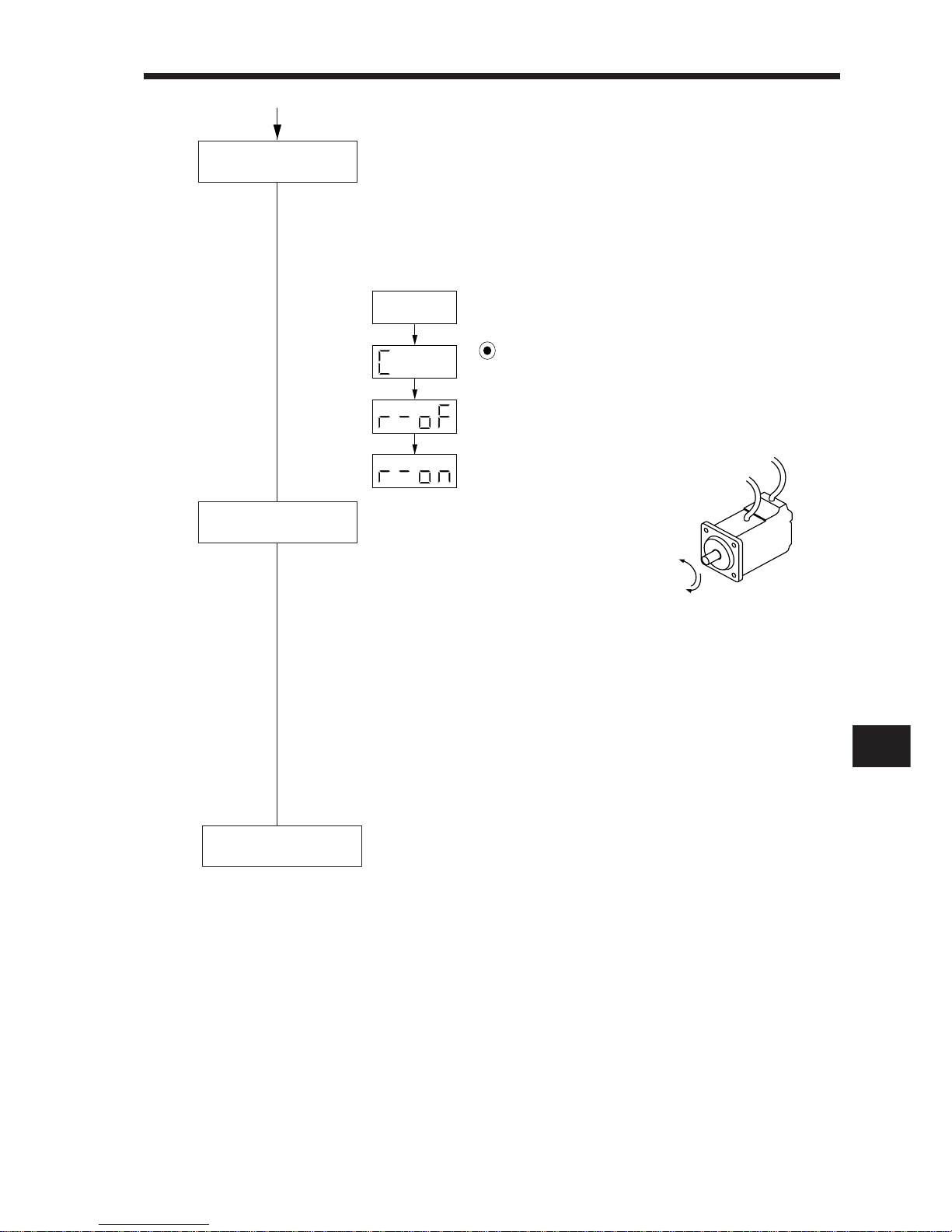
2
2. OPERATION
2– 13
Command pulse
train input
When the servo-on signal (SON) is switched on, the servo amplifier is ready to operate and the servo motor shaft is locked. (Servo
lock state)
If the shaft is not servo-locked, SON is not on. Check the external
sequence on the diagnostic display.
Checking procedure
• When a pulse train is input from the
positioning unit, the servo motor
starts rotating. First, run the servo
motor at low speed and check the rotation direction, etc. If the servo motor does not run as expected, recheck the input signals.
• On the status display monitor, check the servo motor speed, command pulse frequency, load ratios, etc
• When machine operation check is over, confirm automatic operation with the positioning unit program.
• This servo amplifier has the real-time auto tuning function under
model adaptive control. Therefore, starting servo operation automatically makes gain adjustment.
Using parameter No. 2, response level setting can be adjusted to
provide the optimum tuning according to machine rigidity.
Stop
stop signal off
Servo on
Operation is suspended and stopped by:
1) Servo-on signal off ... The base circuit is shut off and the servo
motor coasts.
2) Stroke end signal off ... The servo motor comes to a sudden stop
and is servo-locked. The servo motor is
allowed to run in the opposite direction.
3) Alarm occurrence ... When an alarm occurs, the base circuit
is shut off and the dynamic brake is operated to bring the servo motor to a sudden stop.
4) External emergency ... The base circuit is shut off and the
dynamic brake is operated to bring the
servo motor to a sudden stop. The
display shows A.E6.
This display appears
when SON switches on.
• • • •
Power on
Press MODE once.
Switch SON on.
Forward
rotation
CCW
Reverse
rotation
CW
Page 44
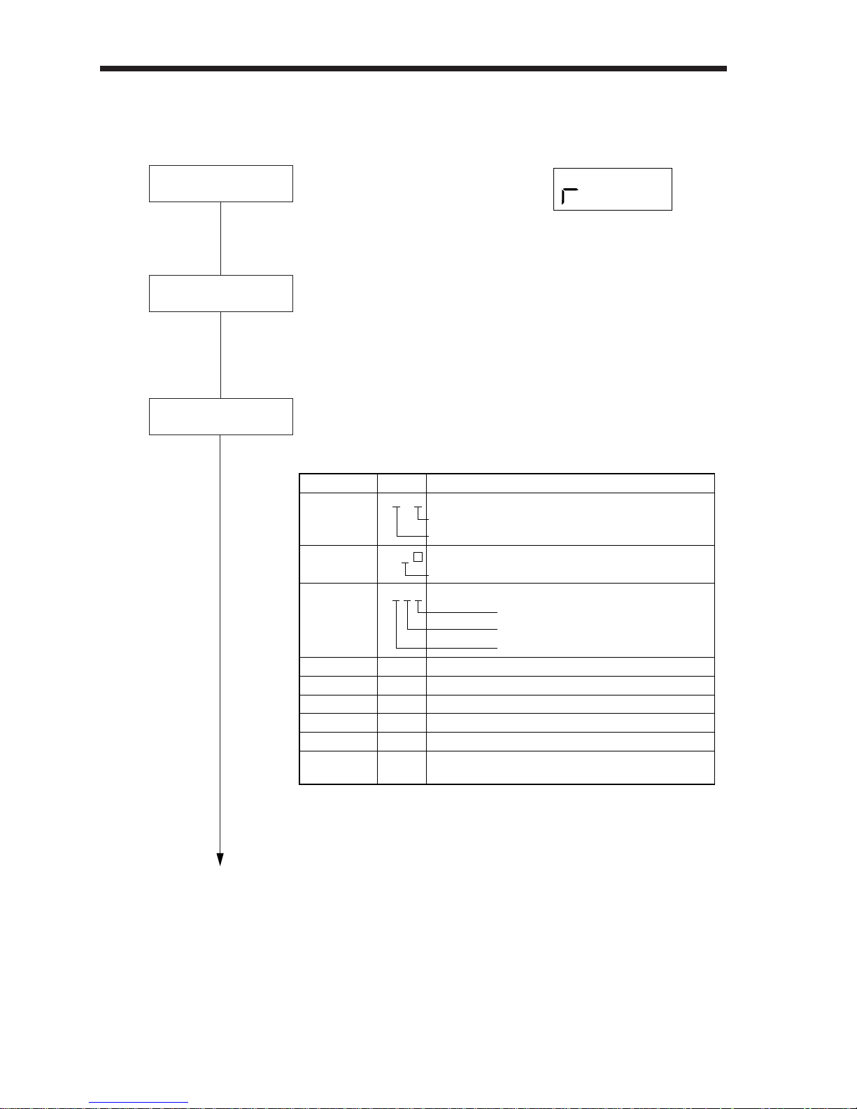
2. OPERATION
2– 14
(3) Speed control mode
Disconnect the servo motor from the machine, make sure that it operates properly , and
reconnect it with the machine.
•Setting example
In the test operation mode, make sure that the servo motor runs. (Refer to (3) in Section 2-3-3.)
Power on
Test operation
1) Switch off the servo-on signal
(SON).
2) When power (NFB) is switched on,
the display shows r (motor speed).
Set the required parameters. (Refer to Section 2-3-5.)
The servo amplifier and servo motor need not be set in parameters
as they are set automatically.
Parameter setting
Parameter Set Value Description
No.0
No.1
No.2
No.8
No.9
No.10
No.11
No.12
No.13
0 0 0 2
0 0 1
0 1 0 1
1000
1500
2000
1000
500
0
Control mode
Regenerative brake option
Electromagnetic brake interlock signal
Auto tuning
Response level
Machine
Used or not used
Internal speed command 1
Internal speed command 2
Internal speed command 3
Acceleration time constant
Deceleration time constant
S-pattern acceleration/deceleration
time constant
: Speed
: Not used.
: Used.
: Low
: Ordinary
: Used
: 1000r/min
: 1500r/min
: 2000r/min
: 1s
: 0.5s
: 0s (not used)
Page 45
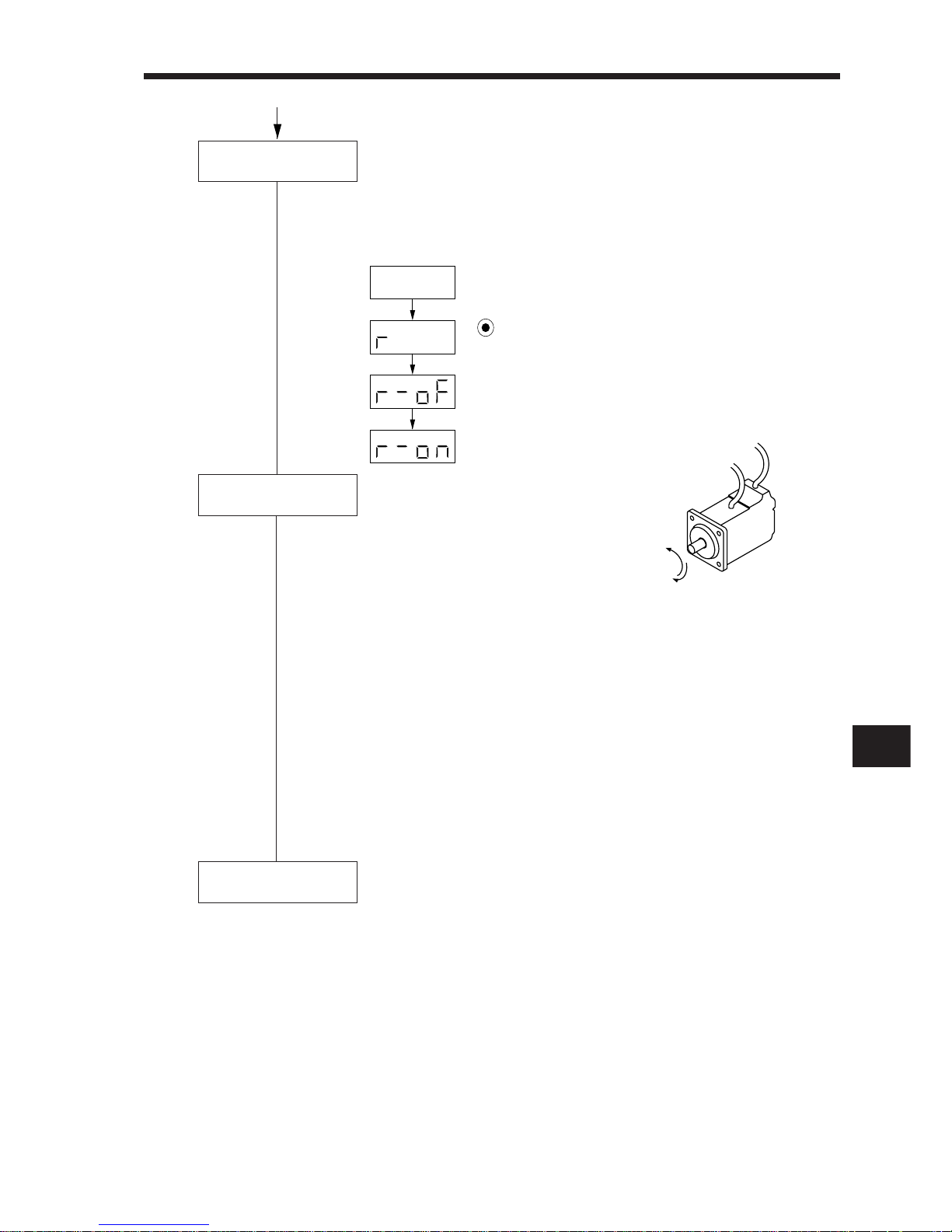
2
2. OPERATION
2– 15
When the servo-on signal (SON) is switched on, the servo amplifier
is ready to operate and the servo motor shaft is locked. (Servo lock
state) If the shaft is not servo-locked, SON is not on. Check the
external sequence on the diagnostic display.
Checking procedure
Forward
rotation
CCW
Reverse
rotation
CW
Servo on
• By selecting speeds (analog speed
command, internal speed commands 1 to 3) with the speed selection 1 signal (SP1) and speed selection 2 signal (SP2) and switching on the start signal (ST1/ST2),
the servo motor starts rotating.
First, run the servo motor at low
speed and check the rotation direction, etc. If the servo motor
does not run as expected, check the input signals and parameters.
• On the status display monitor, check the servo motor speed, load
ratios, etc.
• When machine operation check is over, confirm automatic operation with the host controller or the like.
• This servo amplifier has the real-time auto tuning function under
model adaptive control. Therefore, starting servo operation automatically makes gain adjustment. Using parameter No. 2, response
level setting can be adjusted to provide the optimum tuning according to machine rigidity.
Start
Stop
stop signal off
Operation is suspended and stopped by:
1) Servo-on signal off ... The base circuit is shut off and the servo
motor coasts.
2) Stroke end signal off ... The servo motor comes to a sudden stop
and is servo-locked. The servo motor is
allowed to run in the opposite direction.
3 ) Alarm occurrence ... When an alarm occurs, the base circuit is
shut off and the dynamic brake is operated to bring the servo motor to a sudden stop.
4) External emergency ... The base circuit is shut off and the dy-
namic brake is operated to bring the servo
motor to a sudden stop. The display
shows A.E6.
Power on
Press MODE once.
Switch SON on.
This display appears
when SON switches on.
• •••
Page 46
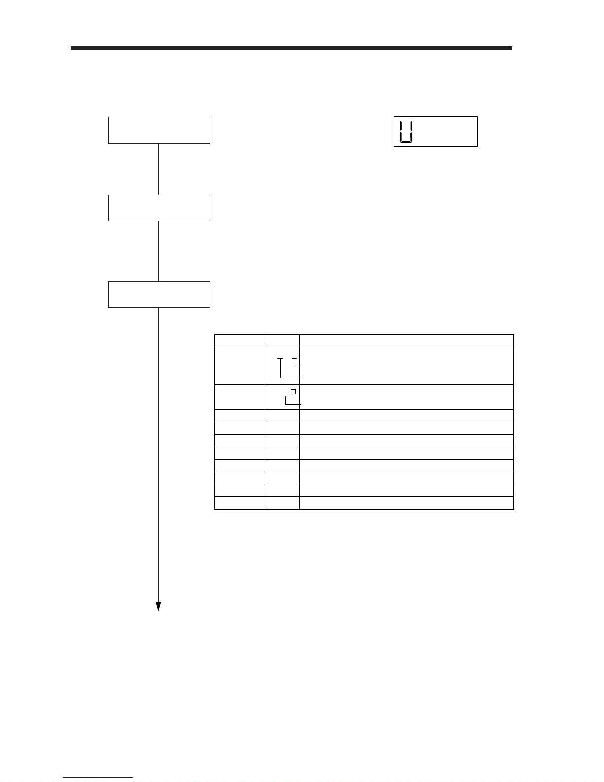
2. OPERATION
2– 16
Set the required parameters. (Refer to Section 2-3-5.)
The servo amplifier and servo motor need not be set in parameters
as they are set automatically .
Power on
Test operation
Parameter setting
1) Switch off the servo-on signal
(SON).
2) When power (NFB) is switched on,
the display shows U (torque command voltage).
In the test operation mode, make sure that the servo motor runs.
(Refer to (3) in Section 2-3-3.)
(4) Torque control mode
Disconnect the servo motor from the machine, make sure that it operates properly, and reconnect it with the machine.
•Setting example
Parameter
Set Value
Description
No.0
No.1
No.8
No.9
No.10
No.11
No.12
No.13
No.14
No.28
0 0 0 4
0 0 0
1000
1500
2000
1000
500
0
2000
50
Control mode
Regenerative brake option
Electromagnetic brake interlock signal
Internal speed command 1
Internal speed command 2
Internal speed command 3
Acceleration time constant
Deceleration time constant
S-pattern acceleration/deceleration time constant
Torque command time constant
Internal torque limit 1
: Torque
: Not used.
: Not used.
: 1000r/min
: 1500r/min
: 2000r/min
: 1s
: 0.5s
: 0s (not used)
: 2s
:
Controlled to 50% output.
Page 47
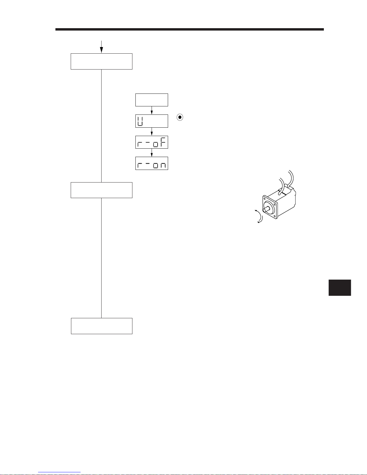
2
2. OPERATION
2– 17
When the servo-on signal (SON) is switched on, the servo amplifier is
ready to operate.Check the external sequence on the diagnostic
display.
Forward
rotation
CCW
Reverse
rotation
CW
Servo on
Start
Stop
Checking procedure
• By selecting speeds (analog
speed command, internal speed
commands 1 to 3) with the speed
selection 1 signal (SP1) and
speed selection 2 signal (SP2)
and switching on the forward/
reverse rotation selection signal
(RS1/RS2), the servo motor
starts rotating. For the torque generation direction, refer to (3) in
Section 3-1-3.First, set the limit speed to low speed and check the
rotation direction, etc. If the servo motor does not run as expected,
recheck the input signals.
• On the status display monitor, check the servo motor speed, load
ratios, etc.
• When machine operation check is over, confirm automatic operation
with the host controller or the like.
Operation is suspended and stopped by:
1) Servo-on signal off ... The base circuit is shut off and the servo
motor coasts.
2) Alarm occurrence ... When an alarm occurs, the base circuit is
shut off and the dynamic brake is operated
to bring the servo motor to a sudden stop.
3) External emergency ... The base circuit is shut off and the dynamic
brake is operated to bring the servo motor
to a sudden stop. The display shows A.E6.
stop signal off
Power on
Press MODE once.
Switch SON on.
• • • •
This display appears
when SON switches on.
Page 48
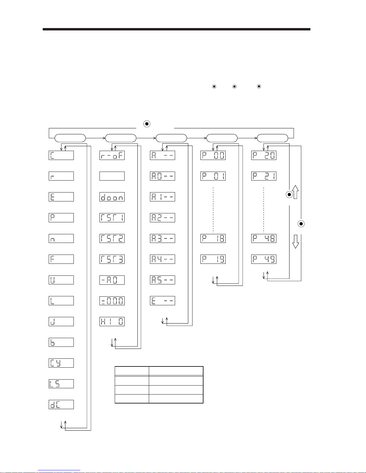
2. OPERATION
2– 18
Status display
Cumulative feedback pulses
[pulse]
Motor speed
[r/min]
Droop pulses
[pulse]
Cumulative command pulses
[pulse]
Command pulse frequency
[kpps]
Speed command voltage
Speed limit voltage[mV]
Torque limit voltage
Torque command voltage[mV]
Regenerative load ratio
[%]
Effective load ratio
[%]
Peak load ratio
[%]
Within one-revolution position
[pulse]
ABS counter
[rev]
Load inertia moment ratio
[times]
Diagnosis
Sequence
External I/O
signal display
Output signal
forced output
Test operation
Jog feed
Test operation
Positioning operation
Test operation
Motor-less operation
Software
version L
Software
version H
Automatic VC
offset
Current alarm
Last alarm
Second alarm
in past
Third alarm
in past
Fourth alarm
in past
Fifth alarm
in past
Sixth alarm
in past
Parameter
error No.
Basic parameters
Servo type
Selective function 1
Status display
Parameter write
disable
Expansion parameters
Selective function 2
Selective function 3
Input signal selection 7
Output signal selection 1
MODE
UP
DOWN
Alarm
(Note)
(Note)
(Note)
button
2-3 Display and Operation
2-3-1 Display flowchart
Use the display (4-digit, 7-segment LED) on the front panel of the servo amplifier for status display,
parameter setting, etc. Set the parameters before operation, diagnose an alarm, confirm external
sequences, and/or confirm the operation status. Press the
MODE
, UP or
DOWN
button once to
move to the next screen. In the position control mode, switching power on displays the symbol C
of the cumulative feedback pulses.
To refer to and/or set the expansion parameters, make them valid with parameter No. 19 (parameter
write disable).
Control Mode
Position
Speed
Torque
Initial Display
Cumulative feedback pulses (C)
Motor speed (r)
Torque command voltage (U)
Note: The initial status display at power-on depends on the control mode.
Page 49
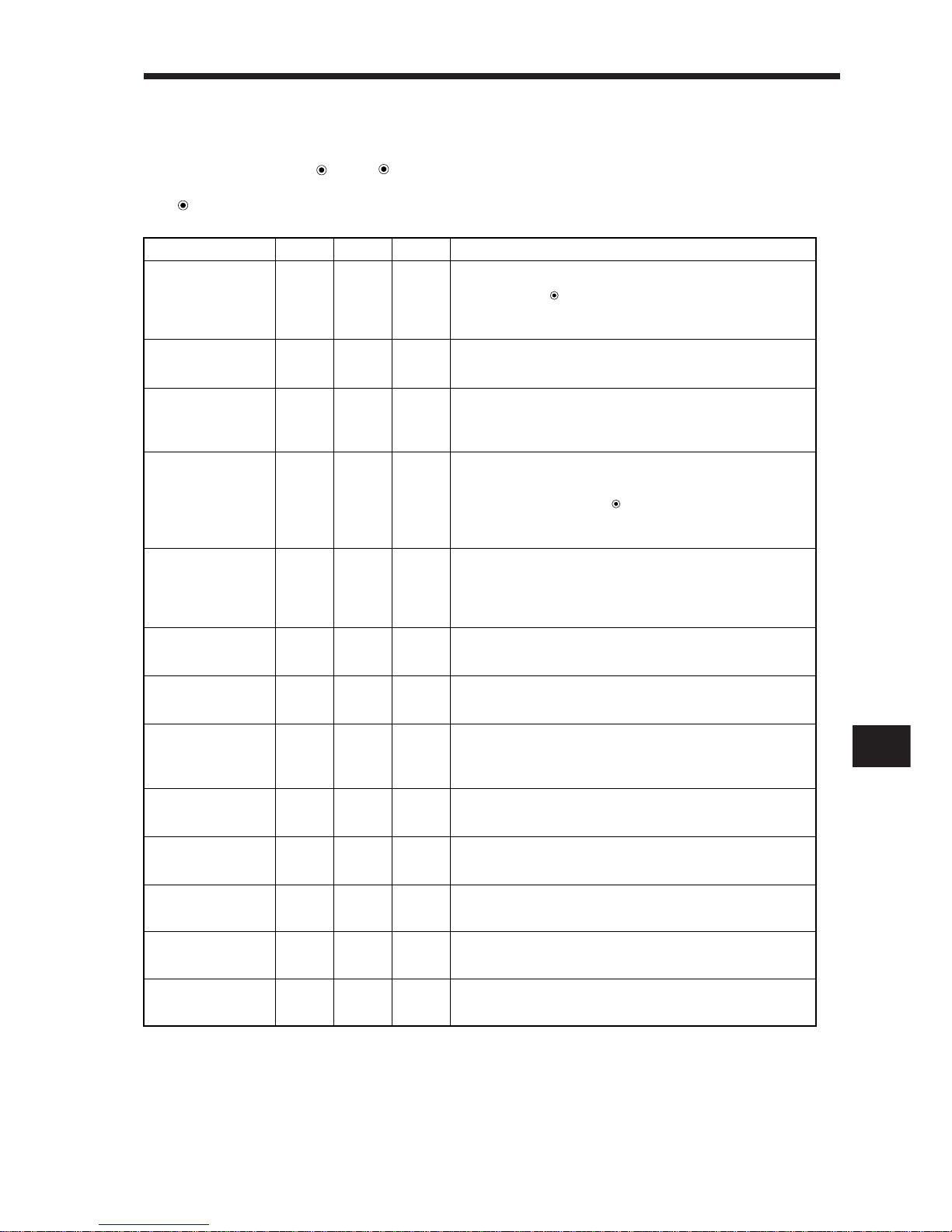
2
2. OPERATION
2– 19
2-3-2 Status display
The servo status during operation is shown on the 4-digit, 7-segment
LED display.Press the UP or
DOWN
button to change display data as desired.
When the required data is selected, the corresponding symbol is displayed. Press
the
SET
button to display that data.
Name Symbol
Display
Range
Unit Description
The ratio of regenerative power to permissible regenerative
power is displayed in %.As the permissible regenerative
power depends on whether there is the regenerative brake
option or not, set parameter No. 0 correctly.
The continuous effective load torque is displayed.When rated
torque is generated, this value is 100%. The effective value
for the past 15 seconds is displayed.
Position within one revolution is displayed in encoder pulses.When
the value exceeds 9999, it begins with 0.
The maximum torque generated during acceleration/deceleration,
etc. is When rated torque is generated, this value is 100%.The peak
torque for the past 15 seconds is displayed.
The estimated ratio of the load inertia moment to the servo
motor shaft inertia moment is displayed.
SET
Travel value from the home position (0) in the absolute position
detection system is displayed in terms of the absolute position
detector's counter value.
Cumulative feedback
pulses
C
-9999
to
9999
Servo motor speed
r
-5400
to
5400
Droop pulses
E
-9999
to
9999
Cumulative command
pulses
P
-9999
to
9999
Command pulse
frequency
n
-400
to
400
Analog speed command voltage
Analog speed limit voltage
F
-10.00
to
10.00
Analog torque command voltage
Analog torque limit voltage
U
-10.00
to
10.00
Regenerative
load ratio
L
0
to
100
Effective load
ratio
J
0
to
300
Peak load ratio
b
0
to
400
Within one-revolution
position
Cy
-9999
to
9999
ABS counter
LS
-9999
to
9999
Load inertia moment
ratio
dc
0.0
to
100.0
pulse
r/min
pulse
kpps
V
V
%
%
%
pulse
rev
Times
pulse
Analog torque command voltage or analog torque limit voltage
is displayed.
Analog speed command voltage or analog speed limit voltage
is displayed.
The frequency of the position command input pulses is
displayed. This value is displayed before it is multiplied by the
electronic gear (CMX/CDV). When the servo motor is rotating
in the reverse direction, the decimal points in the upper 3
digits are lit.
The position command input pulses are counted and
displayed.As this value is displayed before it is multiplied by the
electronic gear (CMX/CDV), it may not match the cumulative
feedback pulses.Press the button to reset the display value
to zero. When the servo motor is rotating in the reverse
direction, the decimal points in the upper 3 digits are lit.
The number of droop pulses in the deviation counter is
displayed. When the value exceeds ±9999, it begins with
zero.When the servo motor is rotating in the reverse direction,
the decimal points in the upper 3 digits are lit.
The servo motor speed is displayed.When the servo motor is
rotating in the reverse direction, the decimal points in the upper 3
digits are lit.The value rounded off is displayed in x 0.1r/min.
Feedback pulses from the servo motor encoder are counted
anddisplayed.When the value exceeds 9999, it begins with
zero.Press the button to reset the display value to zero.
When the servo motor is rotating in the reverse direction, the
decimal points in the upper 3 digits are lit.
SET
Page 50
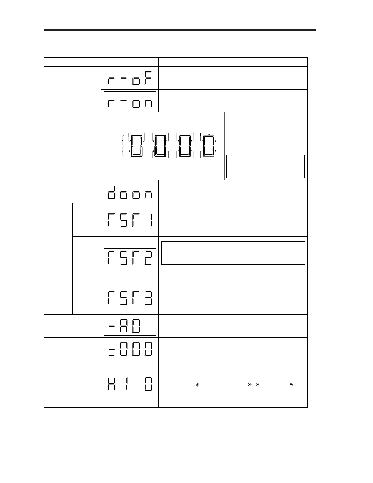
2. OPERATION
2– 20
2-3-3 Diagnostic mode
Name Display Description
Not ready.
Indicates that the servo amplifier is being initialized or an alarm
has
Ready.
Indicates that the servo was switched on after completion of
initialization and the servo amplifier is ready to operate.
The servo motor can be jogged without pulse train input. During jog
feed, the servo amplifier acts as speed control servo.
The status display values of the droop pulses, cumulative command
pulses and command pulse frequency do not change.
For details, refer to (3) in this section.
The digital output signal can be forced on/off. For more information,
refer to (2) in this section.
Indicates the version of the software.
Indicates the system number of the software.
If offset voltages in the analog circuits inside and outside the
servo amplifier cause the servo motor to rotate slowly at the
analog speed command (VC) or analog speed limit (VLA) of 0V,
this function automatically makes zero-adjustment of offset
voltages. Press once, select "1" with / , and press again
to make the automatic VC offset function valid. When this
function is executed, the automatically offset value is set to
parameter No. 29.
Indicates the ON-OFF states of the
external I/O signals.
The upper segments correspond to
the input signals and the lower
segments to the output signals.
Lit: ON
Extinguished: OFF
Input signals
Output signals
CN1A
14
Without connection of the servo motor, the servo amplifier
provides output signals and displays the status as if the servo
motor is running actually in response to the external input
signal. This function can be used to make a sequence check on
the host positioning unit, etc.
For more information, refer to 2), (3) in this section.
CN1B9CN1B
8
CN1A8CN1B14CN1B5CN1B17CN1B
16
CN1B
15
CN1B
7
CN1B4CN1B6CN1B19CN1A18CN1A
19
The set-up software (MRZJW3-SETUP31) is required for positioning operation. This operation
cannot be performed from the operation section
of the servo amplifier.
Output signal forced
output
Automatic VC offset
Software version Low
Software version High
Jog feed
Motorless
operation
Test
operation
mode
The I/O signals can
be changed using
parameters
No. 43 to 49.
Positioning
operation
CN1B
18
The servo motor can be positioned without pulse train input.
SET
UP DOWN
SET
Sequence
External I/O signal
display
NOTICE
NOTICE
Page 51
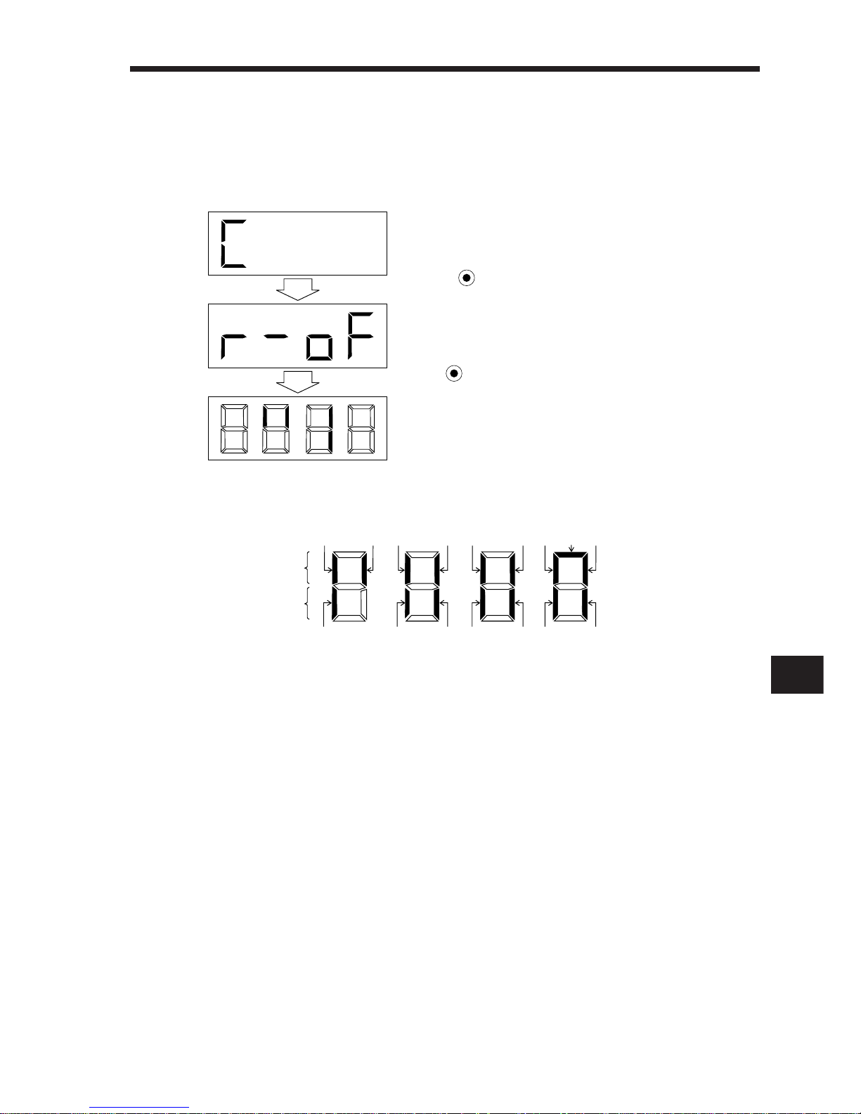
2– 21
2
2. OPERATION
The 7-segment LED shown above indicates ON/OFF.
Each segment at top indicates the input signal and each segment at bottom indicates the output signal.The signals corresponding to the pins in the respective control modes are indicated below:
(1) External I/O signal display
The ON/OFF states of the digital I/O signals connected to the servo amplifier can be confirmed.
1) Operation
Call the display screen shown after power-on.
2) Display definition
External I/O signal display screen
• •• •••••
Press MODE once.
Press UP once.
Input signals
Output signals
CN1A
14
CN1B9CN1B
8
CN1A8CN1B14CN1B5CN1B17CN1B
16
CN1B
15
CN1B
7
CN1B4CN1B6CN1B19CN1A18CN1A
19
Lit: ON
Extinguished: OFF
CN1B
18
Page 52
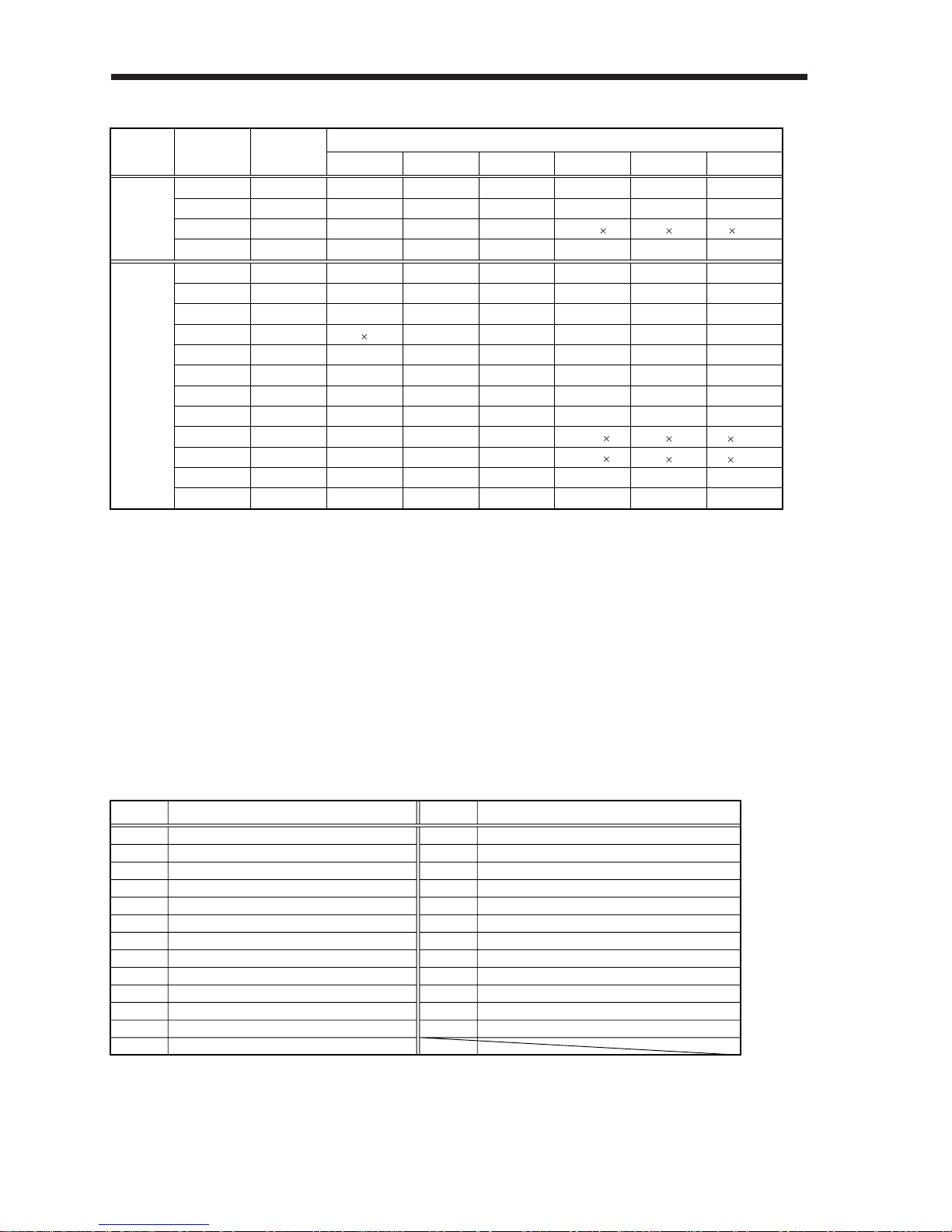
2– 22
2. OPERATION
Note: 1. I: Input signal, O: Output signal
2. P: Position control mode, S: Speed control mode, T: Torque control mode, P/S: Position/
speed control change mode, S/T: Speed/torque control change mode, T/P: Torque/position control change mode
3. Set parameter No. 45 to use CR.
4. Set parameter No. 47 to use PC.
5. Set parameter No. 48 to use TL.
6. Set parameter No. 49 to use WNG and BWNG.
7. Set parameters No. 43 to 48 to change signals.
8. Set parameter No. 49 to output the alarm code. (Refer to Chapter 8.)
9. The signal of CN1A-18 is always output.
a. Control modes and I/O signals
b. Symbols and signal names
Connector
Pin No.
(Note 2) Symbols of I/O Signals in Control Modes
(Note 1) I/O
Signal
Input/Output
P P/S
S S/T T T/P
I
CN1A
8 CR CR/SP1 (Note 3)SP1 SP1 (Note 3)SP1 SP1/CR
O14 OP OP OP OP OP OP
O
(Note 6,8)
18 INP INP/SA SA SA/ /INP
I(Note 7)5 SON SON SON SON SON SON
CN1B
O TLC TLC TLC TLC/VLC VLC VLC/TLC(Note 6)6
I LOP SP2 LOP SP2 LOP(Note 7)7
I PC PC/ST1 (Note 4)ST1 ST1/RS2 (Note 4)RS2 RS2/PC(Note 7)8
I TL TL/ST2 (Note 5)ST2 ST2/RS1 (Note 5)RS1 RS1/TL(Note 7)9
I RES RES RES RES RES RES(Note 7)14
I EMG EMG EMG EMG EMG EMG15
I LSP LSP LSP LSP/ /LSP16
I LSN LSN LSN LSN/ /LSN17
O ALM ALM ALM ALM ALM ALM
O ZSP ZSP ZSP ZSP ZSP ZSP
(Note 6, 8)
19
(Note 6)18
O(Note 8)19 RD RD RD RD RD RD
O(Note 9)4 DO1 DO1 DO1 DO1 DO1 DO1
Symbol
SON
LSP
LSN
CR
SP1
SP2
PC
ST1
ST2
RS1
RS2
TL
RES
Servo on
Forward rotation stroke end
Reverse rotation stroke end
Clear
Speed selection 1
Speed selection 2
Proportion control
Forward rotation start
Reverse rotation start
Forward rotation selection
Reverse rotation selection
Torque limit
Reset
Symbol
EMG
LOP
TLC
VLC
RD
ZSP
INP
SA
ALM
WNG
OP
BWNG
External emergency stop
Control change
Limiting torque
Limiting speed
Ready
Zero speed
In position
Speed reached
Trouble
Warning
Encoder Z-phase pulse (open collector)
Battery warning
Signal Name Signal Name
Page 53
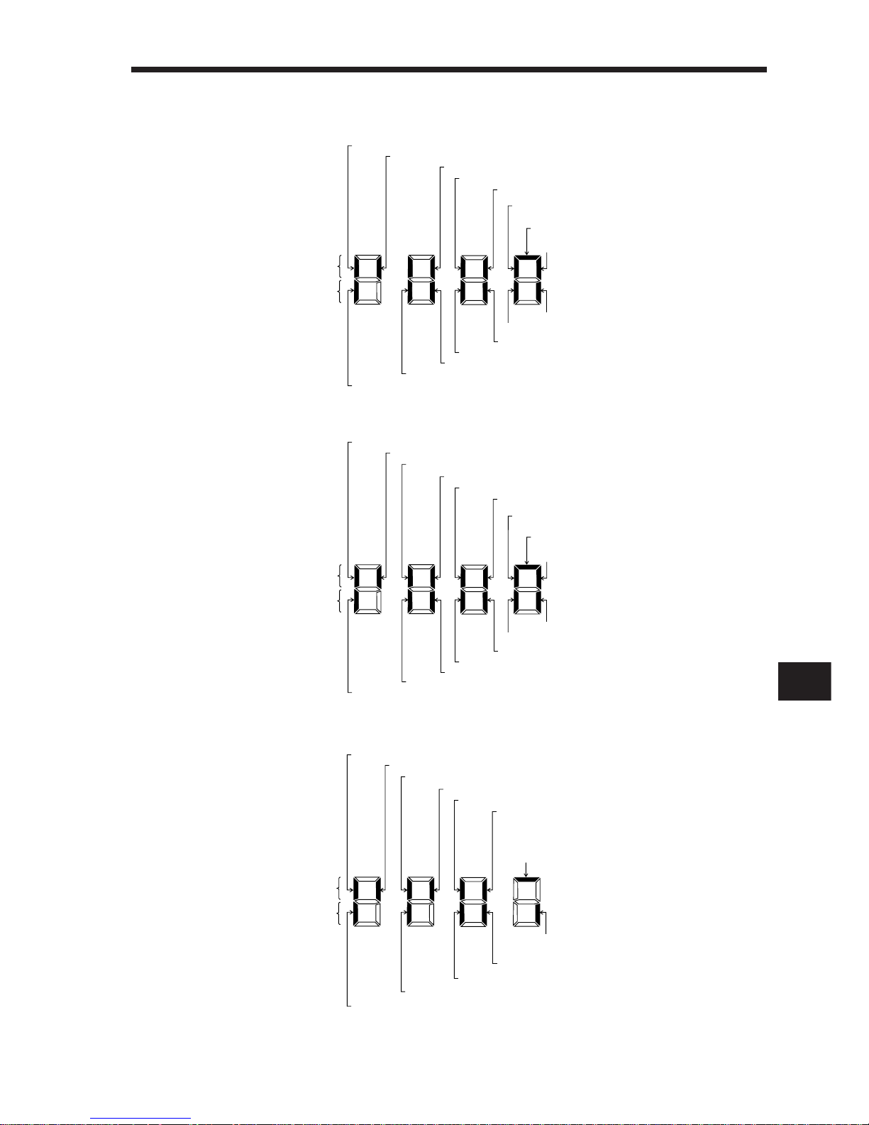
2
2. OPERATION
2– 23
3) Default signal indications
a. Position control mode
TL (CN 1 B-9) Torque limit
Input signals
Output signals
OP (CN 1 A-14) Encoder Z-phase pulse
ALM (CN 1 B-18) Trouble
DO1 (CN 1 B-4) In position
TLC (CN 1 B-6) Limiting torque
ZSP (CN 1 B-19) Zero speed
LNP (CN 1 A-18) In position
RD (CN 1 A-19) Ready
PC (CN 1 B-8) Proportional control
RES (CN 1 B-14) Reset
SON (CN 1 B-5) Servo on
LSN (CN 1 B-17)
Reverse rotation stroke end
LSP (CN 1 B-16)
Forward rotation stroke end
Lit: ON
Extinguished: OFF
CR (CN 1 A-8) Clear
EMG (CN1B-15)
External emergency stop
ST2 (CN 1 B-9) Reverse rotation start
SP2 (CN 1 B-7) Speed selection 2
Input signals
Output signals
OP (CN 1 A-14) Encoder Z-phase pulse
ALM (CN 1 B-18) Trouble
DO1 (CN 1 B-4) In position
TLC (CN 1 B-6) Limiting torque
ZSP (CN 1 B-19) Zero speed
SA (CN 1 A-18) Limiting speed
RD (CN 1 A-19) Ready
ST1 (CN 1 B-8) Forward rotation start
RES (CN 1 B-14) Reset
SON (CN 1 B-5) Servo on
LSN (CN 1 B-17)
External emergency stop
LSP (CN 1 B-16)
Forward rotation stroke end
Lit: ON
Extinguished: OFF
SP1 (CN 1 A-8) Speed selection 1
External emergency stop
EMG (CN 1 B-15)
c. Torque control mode
RS1 (CN 1 B-9) Forward rotation selection
SP2 (CN 1 B-7) Speed selection 2
Input signals
Output signals
OP (CN 1 A-14) Encoder Z-phase pulse
ALM (CN 1 B-18) Trouble
VLC (CN 1 B-6) Speed reached
ZSP (CN 1 B-19) Zero speed
RD (CN 1 A-19) Ready
RS2 (CN 1 B-8) Reverse rotation selection
RES (CN 1 B-14) Reset
SON (CN 1 B-5) Servo on
EMG (CN 1 B-15) External emergency stop
Lit: ON
Extinguished: OFFF
SP1 (CN 1 A-8) Speed selection 1
b. Speed control mode
Page 54
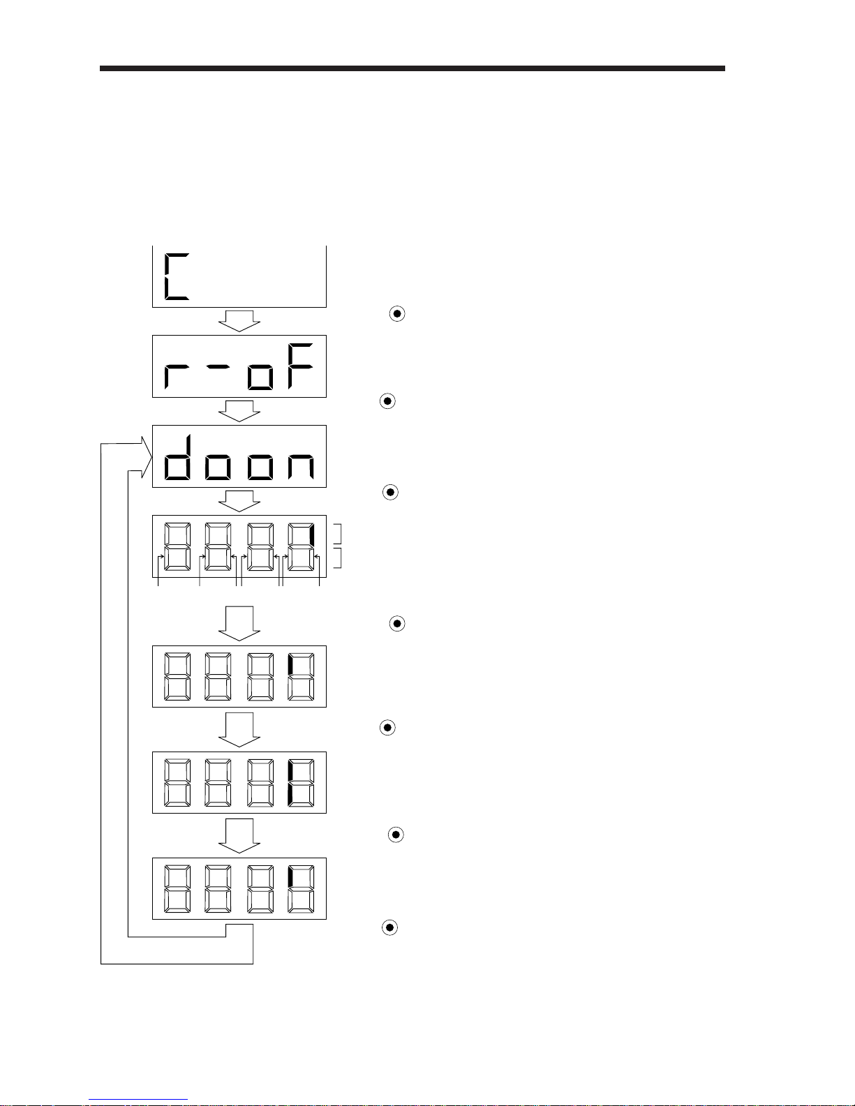
2. OPERATION
2– 24
(2) Output signal forced output
The output signal can be forced on/off independently of the servo status. This function is used
for output signal wiring check, etc. This operation must be performed in the servo off state
(SON signal off).
Operation
Call the display screen shown after power-on.
Switch on/off the signal below the lit segment.
• • •••••
The segment above CN1A-pin 18 is lit.
• • •••••
CN1A-pin 18 is switched off.
• • •••••
CN1A-pin 18 is switched on.
(CN1A-pin 18-SG conduct.)
• • •••••
Indicates the ON/OFF of the output signal. The correspondences
between segments and signals are as in the output signals of the
external I/O signal display.
(Lit: ON, extinguished: OFF)
• • •••••
CN1A
14
CN1B
6
CN1B
4
CN1A
18
CN1B19CN1A
19
CN1B
18
Press MODE once.
Press MODE once.
Press DOWN once.
Press UP twice.
Press UP twice.
Press SET for more than 2 seconds.
Press SET for more than 2 seconds.
Page 55
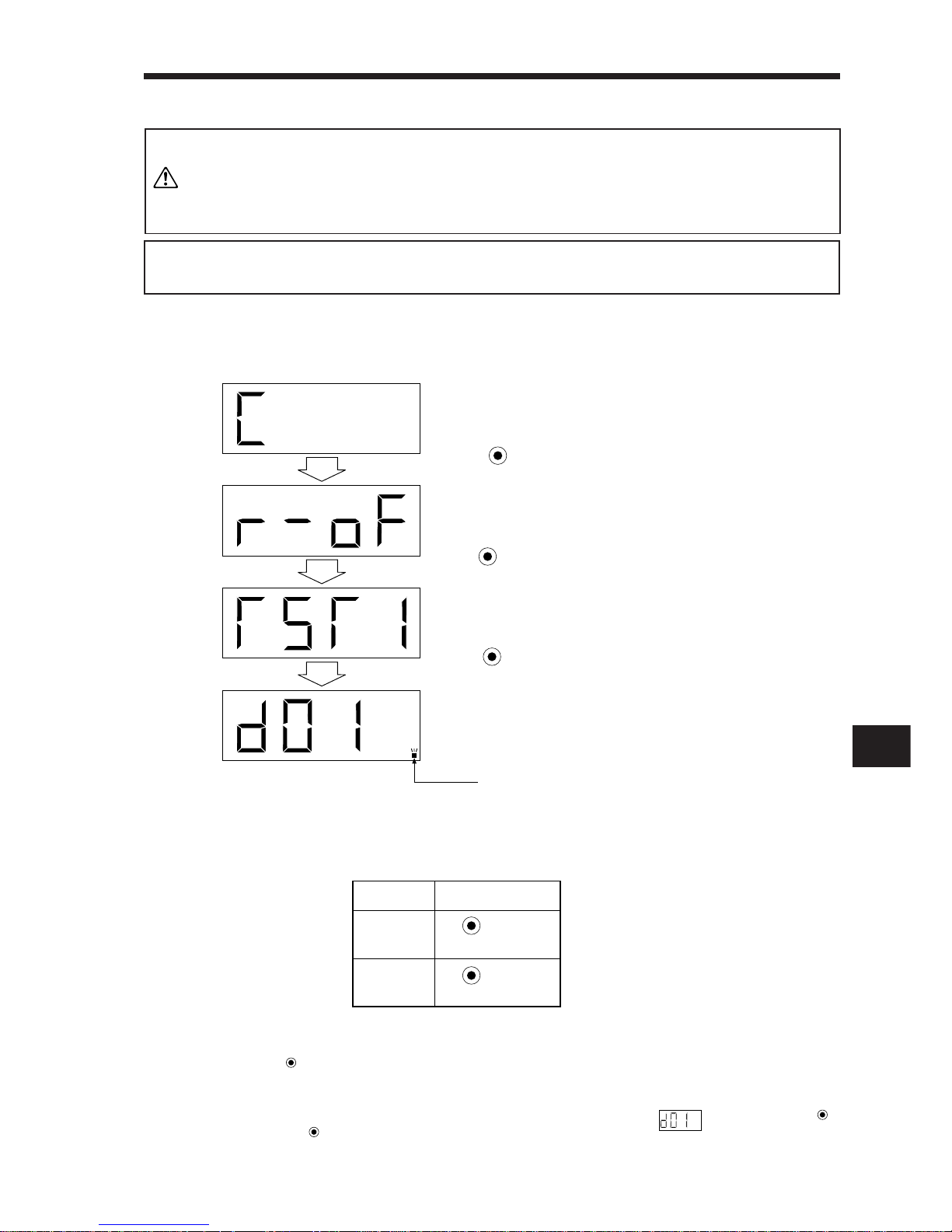
2
2. OPERATION
2– 25
This mode cannot be used for the absolute position detection system.
Set parameter No. 1 to select the incremental positioning system.
MEMORANDUM
(3) Test operation mode
1) Jog feed
Jog feed can be performed without pulse train input from acommand unit or the like.
b. Starting method
Perform the following operation to rotate the servo motor at 200r/min.At this time, the
acceleration/deceleration time constant is 1s. Whenperforming jog feed, connect EMGSG and VDD-COM (when internal power supply is used).
a. Mode change
Call the display screen shown after power-on.
UP
DOWN
Rotation
Direction
CCW
CW
Operation
Press
Press
To stop, release the corresponding button.
c. Status display
Press
MODE
to display the servo status during test operation. The display data is the
same as in the status display in Section 2-3-2.
d. Termination of jog feed
To terminate the jog feed, switch power off once or call the screen using
MODE
and press
SET
for more than 2s.
1.The test operation mode is designed to confirm servo operation and
not to confirm machine operation. In this mode, do not use the servo
motor with the machine.
2.If any operational fault has occurred, stop operation using the external
emergency stop (EMG) signal.
CAUTION
Press UP three times.
When this screen appears, jog feed can be performed.
• • •••••
Flickers in the test operation mode.
Press MODE once.
Press SET for more than 2 seconds.
Page 56
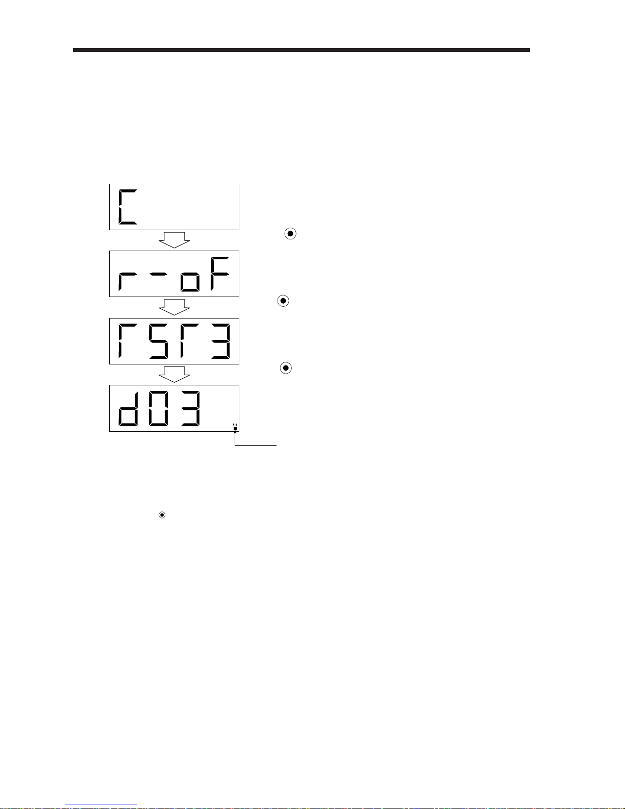
2. OPERATION
2– 26
2) Motor-less operation
Without connection of the servo motor, the servo amplifier can provide output signals and
display the status as if the servo motor is running actually in response to the external input
signal. This function can be used to make a sequence check on the host positioning unit,
etc. Switch off the servo-on signal.
a. Mode change
Call the display screen shown after power-on.
b. Operation method
As in ordinary operation, provide the start signal.
c. Status display
Press
MODE
to shift to the status display screen, on which the status of servo motor
rotation is indicated in simulative value. The display data is the same as in the status
display in Section 2-3-2.
d. Termination of motor-less operation
To terminate the motor-less operation, switch power off.
When this screen is displayed, motor-less operation
can be performed.
• • • • • ••
Flickers in the test operation mode.
Press MODE once.
Press UP five times.
Press SET for more than 2 seconds.
Page 57
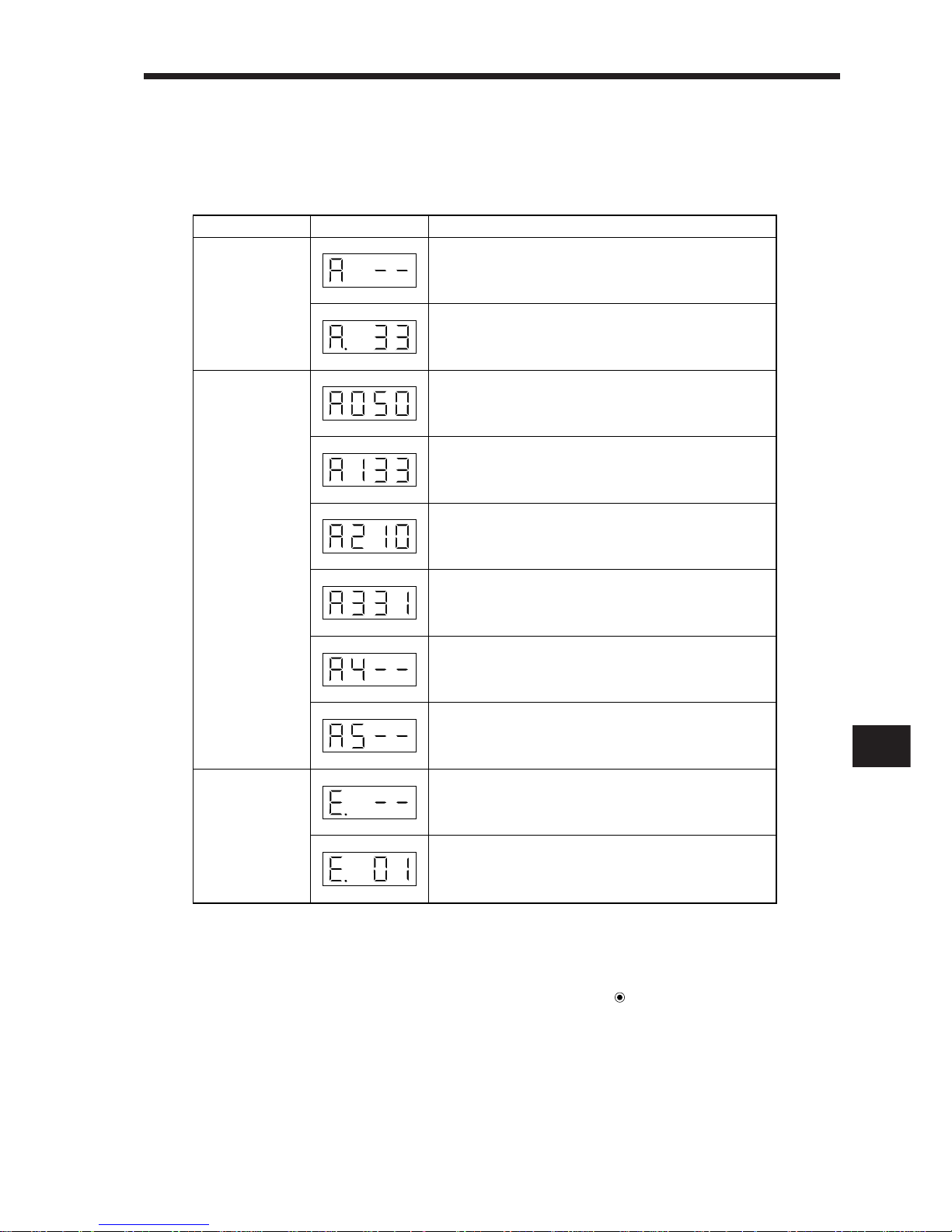
2
2. OPERATION
2– 27
2-3-4 Alarm mode
The current alarm, past alarm history and parameter error are displayed. The lower
2 digits on the display indicate the alarm number that has occurred or the parameter number in error. Display examples are shown below.
Functions at occurrence of an alarm
(1) Any mode screen displays the current alarm.
(2) The other screen is visible during occurrence of an alarm. At this time, the decimal point in the
fourth digit flickers.
(3) To clear any alarm, switch power off, then on or press the
SET
button on the current alarm
screen. Note that this should be done after removing the cause of the alarm.
(4) Use parameter No. 16 to clear the alarm history.
Name Display Description
Current alarm
Indicates no occurrence of an alarm.
Indicates the occurrence of alarm 33 (overvoltage).
Flickers at occurrence of the alarm.
Indicates that the last alarm is alarm 50 (overload 1).
Indicates that the second alarm in the past is alarm 33
(overvoltage).
Indicates that the third alarm in the past is alarm 10
(undervoltage).
Indicates that the fourth alarm in the past is alarm 31
(overspeed).
Indicates that there is no fifth alarm in the past.
Indicates that there is no sixth alarm in the past.
Indicates no occurrence of alarm 37 (parameter error).
Indicates that the data of parameter No. 1 is faulty.
Parameter error
Alarm history
Page 58
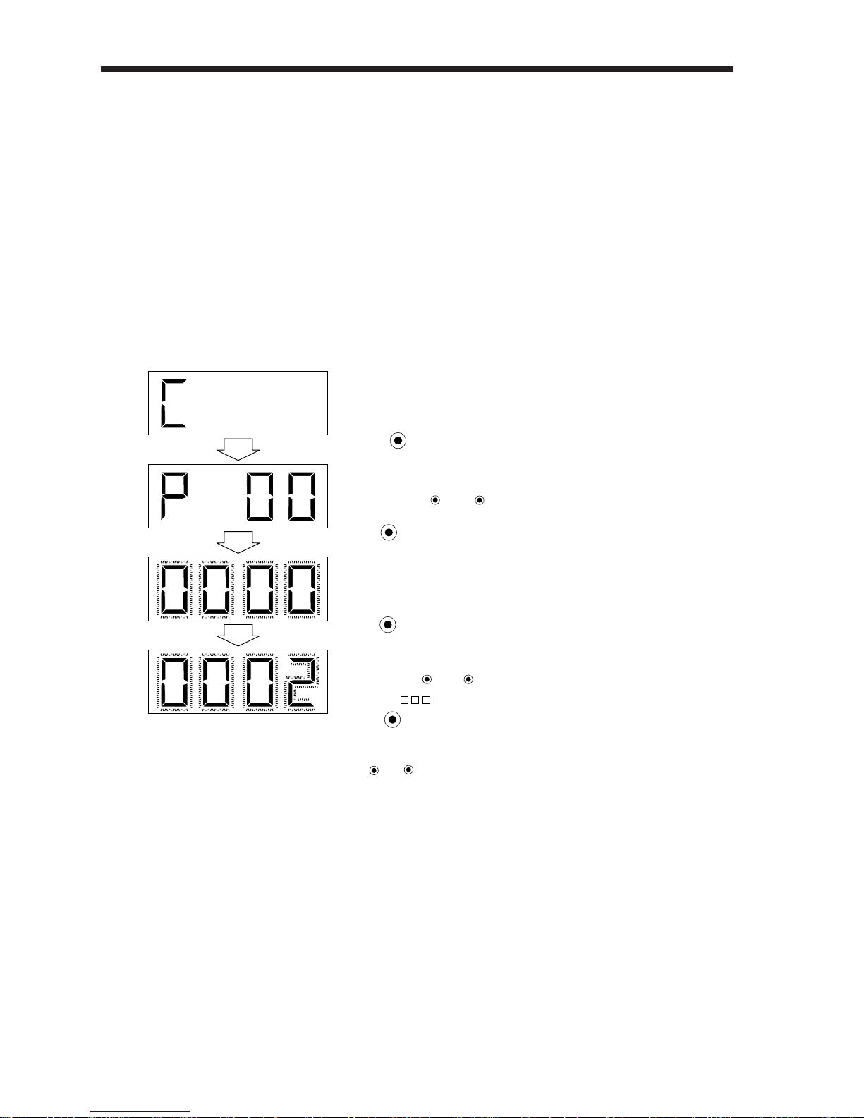
2. OPERATION
2– 28
2-3-5 Parameter mode
The servo amplifier is factory-set in the position control mode. Change the parameter settings
when:
1) The control mode is changed;
2) The regenerative brake option is used;
3) The number of pulses per servo motor revolution is changed
(When the number of pulses per servo motor revolution has been set to the position command unit, set the number of pulses in the parameter of the position command unit unless
the maximum number of pulses is restricted); or
4) The machine mounted with the servo motor hunts or operational performance is further improved.
(1) Operation example
1) 4-digit parameter
The following example shows the operation procedure performed after power-on to place the
servo in the speed control mode:
To shift to the next parameter, press the UP/
DOWN
button.
When changing the parameter No. 0 setting, change its set value, then switch power off once and
switch it on again to make the new value valid.
The parameter number is displayed.
• • •••••
During flickering, the set value can be changed.
Use UP or
DOWN
.
( 2: Speed control mode)
• • •••••
The set value of the specified parameter number flickers.
• • •••••
Press SET to enter.
Press MODE three times.
Press
UP
or
DOWN
to change the number.
Press SET twice.
Press UP once.
Page 59
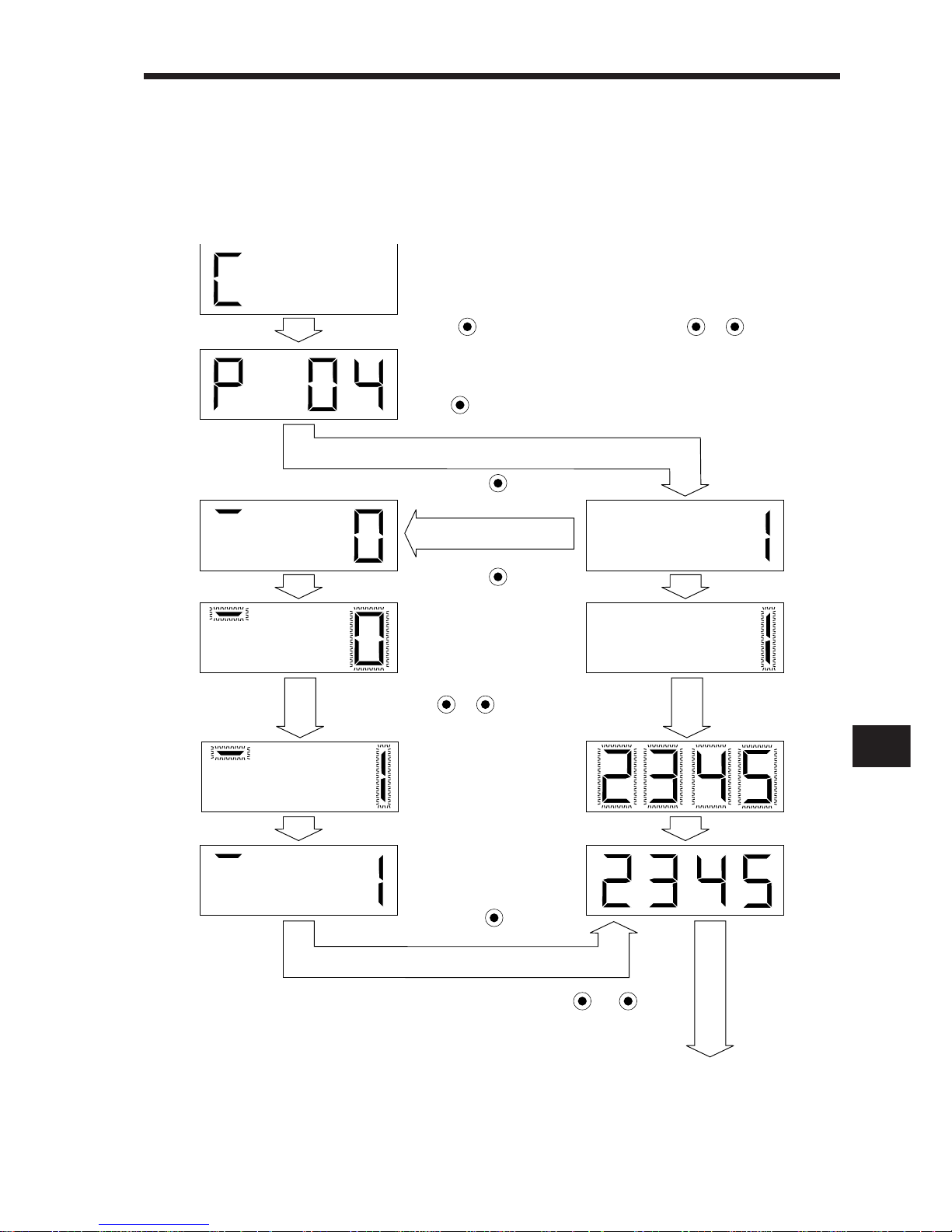
2
2. OPERATION
2– 29
2) 5-digit parameter
The following example shows the operation procedure performed to change the electronic
gear denominator (parameter No. 4) into "12345":
Call the display screen shown after power-on.
To the next parameter
The screen flickers.
• • • • • • • •
The set value is entered.
• • • • • •
Fifth digit setting
Lower 4 digits setting
Press MODE once. Select parameter No. 4 with UP / DOWN .
Press SET once.
Press MODE once.
Press SET once.
Change the set value
with UP / DOWN.
Press SET once.
Press UP or DOWN.
Page 60
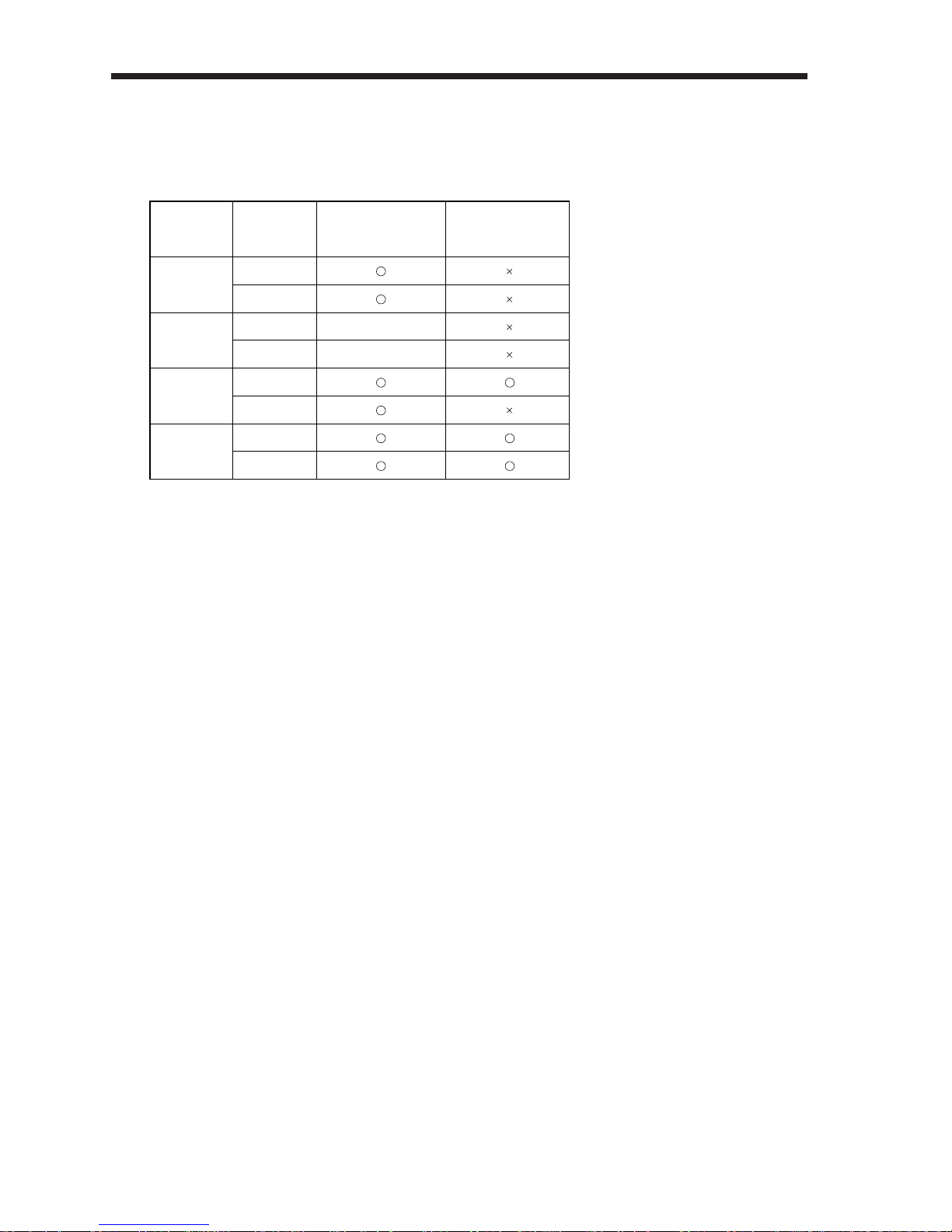
2. OPERATION
2– 30
(2) Expansion parameters
To use the expansion parameters, change the setting of parameter No. 19 (parameter write
disable). After setting parameter No. 19, switch power off once, then switch it on again to make
the parameter valid.
Set Value
0000
(initial value)
000A
000B
000C
Operation
Reference
Write
Reference
Write
Reference
Write
Reference
Write
Basic Parameters
No.0~19
Allowed for No. 19 only
Allowed for No. 19 only
Expansion Parameters
No.20~49
Page 61
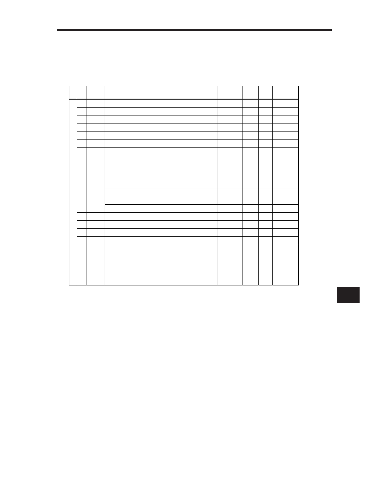
2
2. OPERATION
2– 31
(3) Parameter list
For any parameter whose symbol is preceded by *, set the parameter and switch power off
once, then switch it on again to make that parameter valid.
The symbols in the Control Mode field represent parameters used in the corresponding modes.
(P: Position control mode, S: Speed control mode, T: Torque control mode)
Control mode, regenerative brake option selection
Function selection 1
Auto tuning
Electronic gear (Command pulse multiplying factor numerator)
Electronic gear (Command pulse multiplying factor denominator)
In-position range
Position loop gain 1
Position command acceleration/deceleration time constant (Smoothing)
Internal speed command 1
Internal speed limit 1
Internal speed command 2
Internal speed limit 2
Internal speed command 3
Internal speed limit 3
Acceleration time constant
Deceleration time constant
S-pattern acceleration/deceleration time constant
Torque command time constant
Spare
Communication baudrate selection, alarm history clear
Analog monitor output
Status display selection
Parameter block
*STY
*OP1
ATU
CMX
CDV
INP
PG1
PST
SC1
SC2
SC3
STA
STB
STC
TQC
*BPS
MOD
*DMD
*BLK
P • S • T
P • S • T
P • S
P
P
P
P
P
S
T
S
T
S
T
S • T
S • T
S • T
T
P •S •T
P •S •T
P •S •T
P •S •T
0000
0000
0102
1
1
100
36
3
100
100
500
500
1000
1000
0
0
0
0
0
0000
0100
0000
0000
pulse
rad/s
ms
r / min
r / min
r / min
r / min
r / min
r / min
ms
ms
ms
ms
0
1
2
3
4
5
6
7
8
9
10
11
12
13
14
15
16
17
18
19
No.
Symbol
Name
Control
Mode
Initial
Value
Unit
Customer
Setting
Basic parameters
Page 62
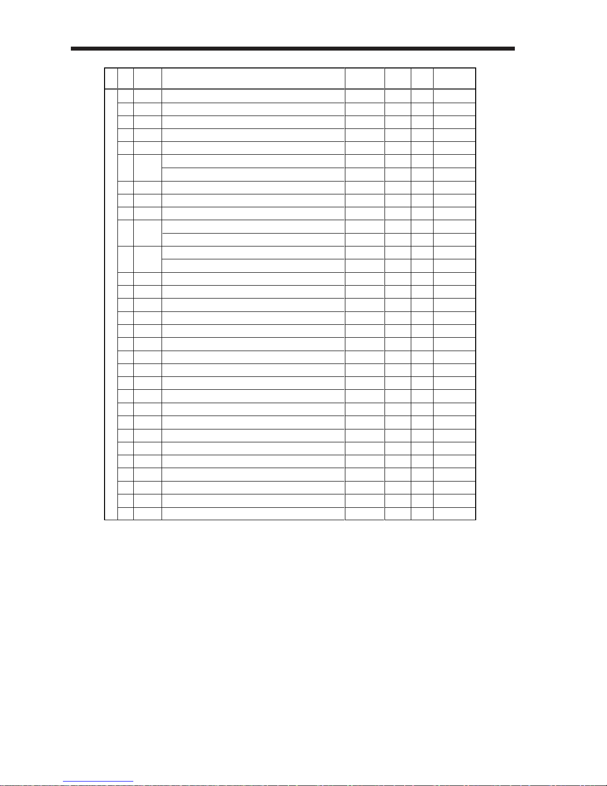
2. OPERATION
2– 32
Function selection 2
Function selection 3 (Command pulse selection)
Function selection 4
Feed forward gain
Zero speed
Analog speed command maximum speed
Analog speed limit maximum speed
Analog torque command maximum output
Encoder output pulses
Internal torque limit 1
Analog speed command offset
Analog speed limit offset
Analog torque command offset
Analog torque limit offset
Analog monitor offset 1
Analog monitor offset 2
Electromagnetic brake sequence output
Ratio of load inertia moment to servo motor inertia moment
Position loop gain 2
Speed loop gain 1
Speed loop gain 2
Speed integral compensation
Speed differential compensation
Spare
Input signal automatic ON selection
Input signal selection 1
Input signal selection 2 (CN1B-pin 5)
Input signal selection 3 (CN1B-pin 14)
Input signal selection 4 (CN1A-pin 8)
Input signal selection 5 (CN1B-pin 7)
Input signal selection 6 (CN1B-pin 8)
Input signal selection 7 (CN1B-pin 9)
Output signal selection 1
*OP2
*OP3
*OP4
FFC
ZSP
VCM
TLC
*ENR
TL1
VCO
TLO
MO1
MO2
MBR
GD2
PG2
VG1
VG2
VIC
VDC
*DIA
*DI1
*DI2
*DI3
*DI4
*DI5
*DI6
*DI7
*DO1
P •S •T
P
P •S •T
P
P •S •T
S
T
T
P •S •T
P •S •T
S
T
T
S
P •S •T
P •S •T
P •S •T
P •S •T
P
P • S
P • S
P • S
P • S
P •S •T
P •S •T
P •S •T
P •S •T
P •S •T
P •S •T
P •S •T
P •S •T
P •S •T
0000
0000
0000
0
50
(Note1)0
(Note1)0
100
4000
100
(Note2)
(Note2)
0
0
0
0
100
70
30
216
714
20
980
0
0000
0003
0111
0222
0665
0770
0883
0994
0000
%
r/min
(r/min)
(r/min)
%
pulse
%
mV
mV
mV
mV
mV
mV
ms
x 0.1times
rad/s
rad/s
rad/s
ms
20
21
22
23
24
25
26
27
28
29
30
31
32
33
34
35
36
37
38
39
40
41
42
43
44
45
46
47
48
49
No.
Symbol
Name
Control
Mode
Initial
Value
Unit
Customer
Setting
Expansion parameters
Note: 1. 0: Rated servo motor speed
2. Depends on the servo amplifier.
Page 63
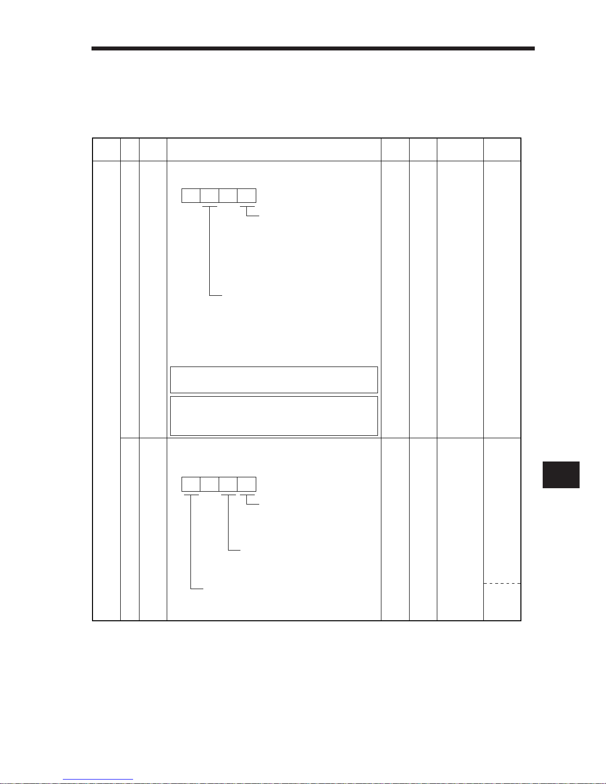
2
2. OPERATION
2– 33
(4) Detailed explanation of the parameters
To make the parameter marked * valid, set the parameter and switch power off once, then
switch it on again.
The symbols in the Control Mode field represent parameters used in the corresponding modes.
(P: Position control mode, S: Speed control mode, T: Torque control mode)
Class No.
Symbol
Initial
Value
Unit
Setting
Range
Control
Mode
Name and Function
0 *STY Control mode, regenerative brake option selection
Used to select the control mode and regenerative brake option.
0000 0000h
to
0605h
P • S • T
Select the control mode.
0: Position
1: Position and speed
2: Speed
3: Speed and torque
4: Torque
5: Torque and position
Select the regenerative brake option.
0: Not used
1: Reserved (do not set)
2: MR – RB032
3: MR – RB12
4: MR – RB32
5: MR – RB30
6: MR – RB50
1 *OP1 Function selection 1:
Used to select the input signal filter, CN1B-pin 19's
output signal and absolute position detection system.
Input signal filter
0: None
1: 1.77ms
2: 3.55ms
CN1B-pin 19's function selection
0: Zero speed detection signal
1: Electromagnetic brake interlock signal
0000 0000h
to
1012h
P • S • T
P
Positioning system
0: Used in incremental positioning system
1: Used in absolute position detection system
Wrong setting may cause the
regenerative brake option to burn.
If the regenerative brake option
selected is not for use with the
servo amplifier, parameter error
(A. 37) occurs.
NOTICE
MEMORANDUM
0
00
Basic parameters
Page 64
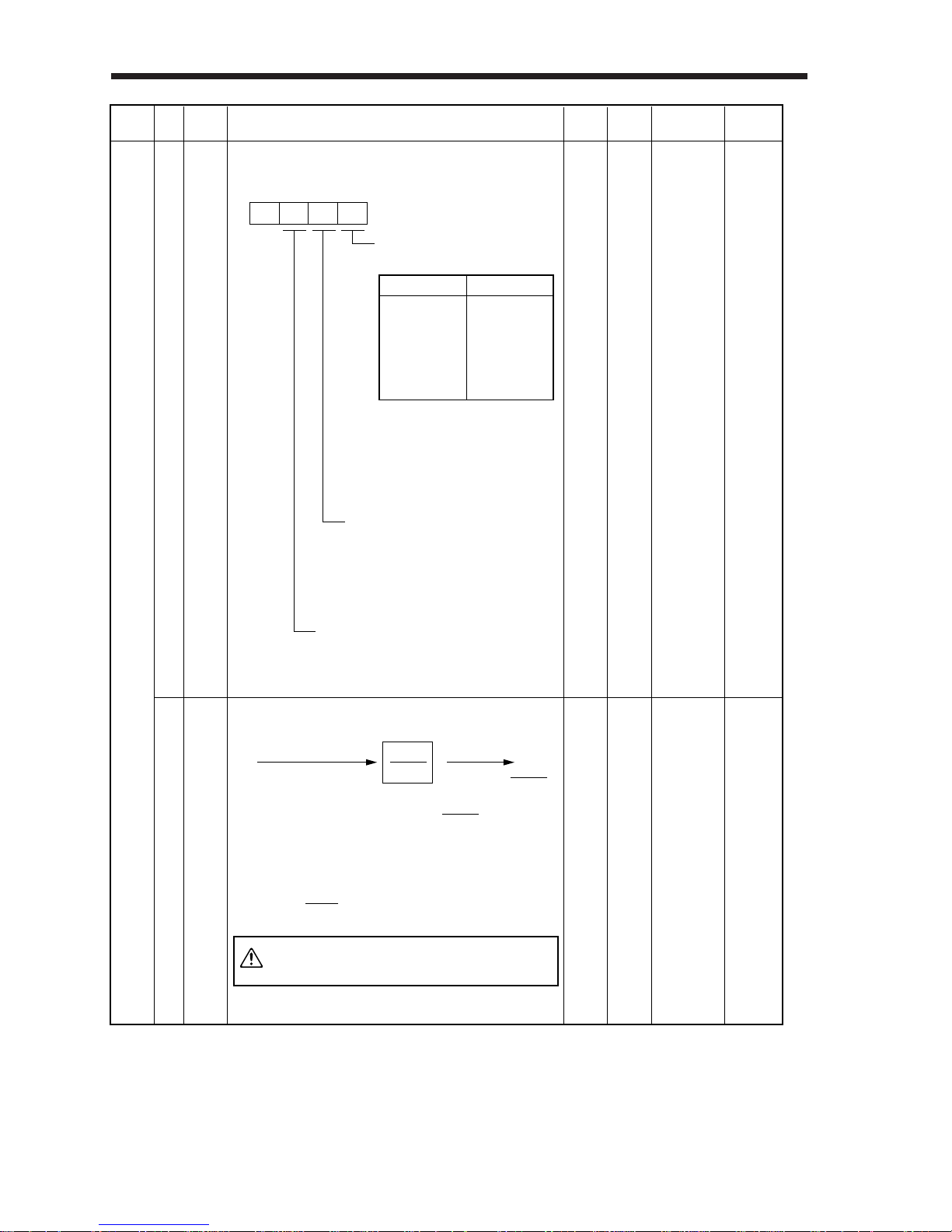
2. OPERATION
2– 34
Class No.
Symbol
Initial
Value
Unit
Setting
Range
Control
Mode
Name and Function
2 ATU Auto tuning:
Used to set the response level, etc. for execution of
auto tuning.
Electronic gear (Command pulse multiplying factor numerator):
Used to set the multiplier of the command pulse input.
Note: Set in the range of 1/50< <50.
0102
1
0001h
to
0215h
P • S
Auto tuning response level
setting
Auto tuning selection
0:
Interpolation axis control(speed loop only)
1:
Executed for both position and speed loops
2: No.
Select the machine.
For example, used to improve the
position settling characteristic
when friction is large.
0: Normal
1: Friction is large
3
CMX
1 to 32767
P
Set Value
1
2
3
4
5
Response Level
Low response
to
Middle response
to
High response
• If the machine hunts or generates
large gear sound, decrease the
set value.
• To improve performance, e.g.
shorten the settling time, increase
the set value.
Command pulse input
Position command
CMX
CDV
CMX
CDV
f
1
f
2 = f1 •
CMX
CDV
The setting of the number of input pulses per servo
motor revolution can be changed by the following
formula:HC-MF series: 8192 pulses/rev)
8192 • [pulse/rev]
CDV
CMX
0
Wrong setting will rotate the
servo motor at unexpectedly
high speed, leading to injury.
CAUTION
Basic parameters
Page 65
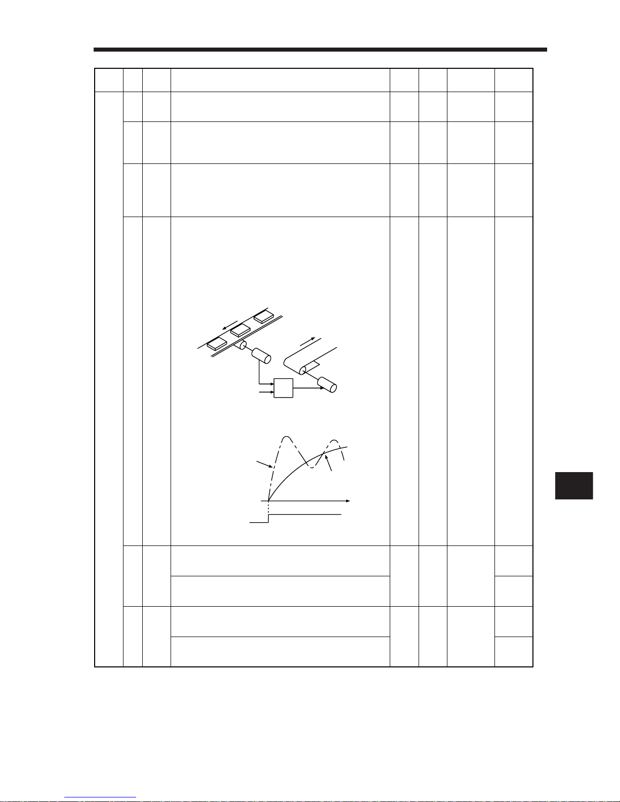
2. OPERATION
2
2– 35
Class No.
Symbol
Initial
Value
Unit
Setting
Range
Control
Mode
Name and Function
Basic parameters
4
5
CDV
INP
Electronic gear (Command pulse multiplying factor denominator):
Used to set the divisor of the command pulse input.
In-position range:
Used to set the droop pulse range in which the inposition (INP) signal will be output.
1
100
1 to 32767
0 to 10000
P
P
pulse
6
PG1
Position loop gain 1:
Used to set the gain of position loop 1.
Increase the gain to improve trackability in response
to the position command.
36
4 to 1000
P
rad/s
8
SC1
Internal speed command 1:
Used to set speed 1 of internal speed commands.
Internal speed limit 1:
Used to set speed 1 of internal speed limits.
100
0 to instan-
taneous per-
missible
speed
S
T
r/min
9
SC2
Internal speed command 2:
Used to set speed 2 of internal speed commands.
Internal speed limit 2:
Used to set speed 2 of internal speed limits.
500
S
T
r/min
7
PST
Position command acceleration/deceleration time constant (smoothing):
Used to set the time constant of a low pass filter in
response to the position command.
Example: When a command is given from a synchronizing detector, synchronous operation can be started
smoothly if started during line operation.
3
0 to 20000
P
ms
Synchronizing
detector
Start
Servo amplifier
Servo motor
Without time
constant setting
With time
constant setting
Start
t
ON
OFF
Servo motor
speed
0 to instan-
taneous per-
missible
speed
Page 66
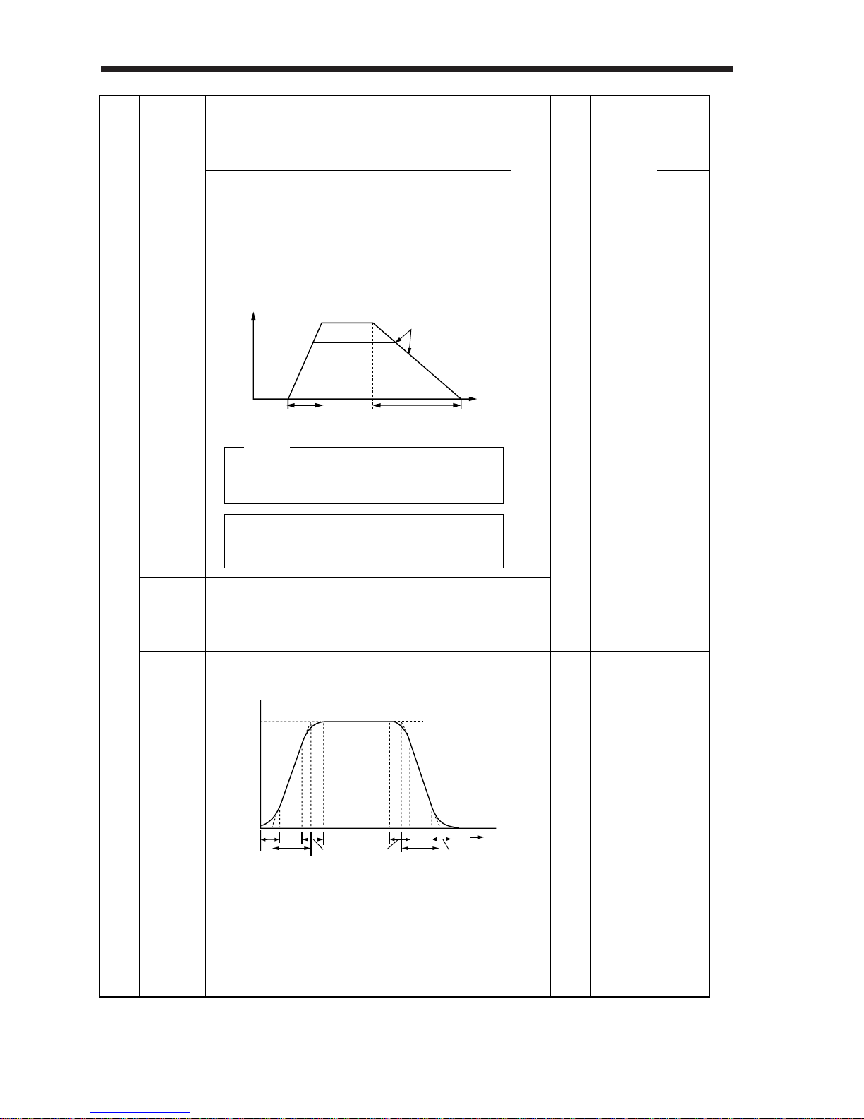
2. OPERATION
2– 36
Basic parameters
10
SC3
Internal speed command 3:
Used to set speed 3 of internal speed commands.
1000
S
Internal speed limit 3:
Used to set speed 3 of internal speed limits.
T
11
STA
Acceleration time constant:
Used to set the acceleration time required to reach the
rated speed from zero speed in response to the analog
speed command and internal speed commands 1 to 3.
0
0 to 20000
S • T
ms
13
STC
S-pattern acceleration/deceleration time constant:
Used to smooth start/stop of the servo motor.
0
0 to 1000
S • T
ms
12
STB
Deceleration time constant:
Used to set the deceleration time required to reach
zero speed from the rated speed in response to the
analog speed command and internal speed commands
1 to 3.
0
r/min
Set 3000 (3s) to accelerate the HC-MF series servo
motor (rated speed: 3000r/min) from 0r/min to 1000
r/min in 1 second.
If the preset command speed is
lower than the rated speed,
acceleration/deceleration time
will be shorter.
Time
Parameter
No. 12 setting
Parameter
No. 11 setting
Speed
Rated
speed
Zero
speed
Command
speed
Servo motor
speed
Zero
speed
STC
STA
STC
STC
STB
STC
Time
STA: Acceleration time constant (parameter No. 11)
STB: Deceleration time constant (parameter No. 12)
STC: S-pattern acceleration/deceleration time con stant (parameter No. 13)
Class No.
Symbol
Initial
Value
Unit
Setting
Range
Control
Mode
Name and Function
0 to instan-
taneous per-
missible
speed
Example
NOTICE
When configuring an external position loop,
set 0 or minimal values in parameters No.
11 and 12.
Page 67
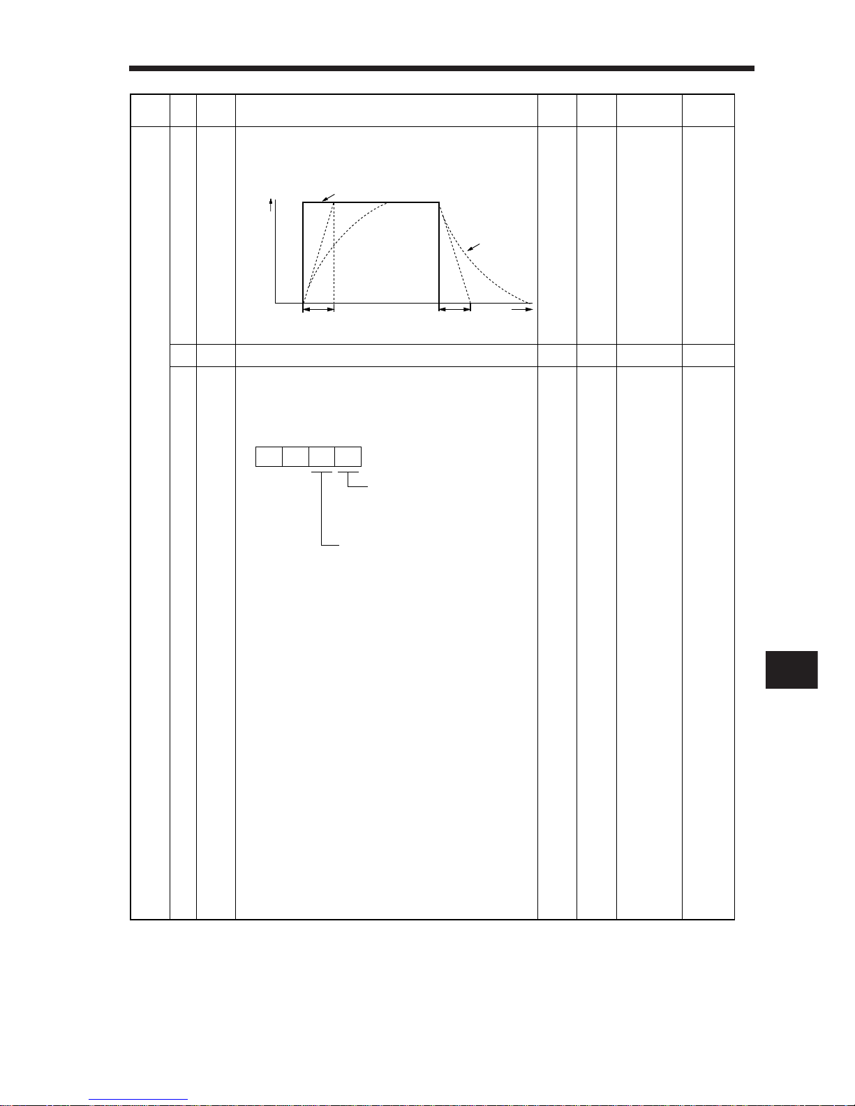
2. OPERATION
2
2– 37
14
TQC
Torque command time constant:
Used to set the constant of a low pass filter in response
to the torque command.
0
0 to 20000
T
15
Spare
0
ms
16 *BPS 0000 0000h
to
0011h
P • S • T
Communication baudrate selection, alarm history clear:
Used to select the communication baudrate for use of
the set-up software and to clear the alarm history.
Selection of baudrate for RS-232C
0: 9600 [bps]
1: 19200 [bps]
Alarm history clear
0: Invalid
1: Valid
When alarm history clear is made
valid, the alarm history is cleared
at next power-on. After the alarm
history is cleared, the setting is
automatically made invalid (reset to 0).
0
Torque
Torque command
After
filtered
TQC TQC
TQC: Torque command time constant
Time
0
Class No.
Symbol
Initial
Value
Unit
Setting
Range
Control
Mode
Name and Function
Basic parameters
Page 68
2. OPERATION
2– 38
17 MOD 0100 0000h
to
0A0Ah
P • S • T
Analog monitor output:
Used to set the signal output for analog monitor.
Analog monitor CH1 output
selectionThe set values and
their definitions are as in analog
monitor CH2.
Analog monitor CH2 output selection
0: Servo motor speed
(±8V/max. speed)
1: Torque (±8V/max. torque)
2: Servo motor speed
(+8V/max. speed)
3: Torque (+8V/max. torque)
4: Current command output
(±8V/max. command current)
5: Command pulse frequency
(±8/400kpps)
6: Droop pulses 1/1
(±10V/128 pulses)
7: Droop pulses 1/16
(±10V/2048 pulses)
8: Droop pulses 1/64
(±10V/8192 pulses)
9: Droop pulses 1/256
(±10V/32768 pulses)
10: Droop pulses 1/1024
(±10V/131072 pulses)
00
Class No.
Symbol
Initial
Value
Unit
Setting
Range
Control
Mode
Name and Function
Basic parameters
Page 69
2. OPERATION
2
2– 39
18 *DMD 0000 0000h
to
001Ch
P • S • T
Status display selection:
Used to select the status display shown at power-on.
Selection of status display at
power-on
0: Cumulative feedback pulses
1: Servo motor speed
2: Droop pulses
3: Cumulative command pulses
4: Command pulse frequency
5:
Analog speed command voltage
(Note 1)
6:
Analog torque command voltage
(Note 2)
7: Regenerative load ratio
8: Effective load ratio
9: Peak load ratio
A:
Within one-revolution position
B: ABS counter
C: Load inertia moment ratio
Status display at power-on in
corresponding control mode
0: Depends on the control mode.
0
Note: 1. In speed control mode. Analog
speed limit voltage in torque
control mode.
2. In torque control mode. Analog
torque limit voltage in speed or
position control mode.
Control
Mode
Position
Position/speed
Speed
Speed/torque
Torque
Torque/position
Status Display at Power-On
Cumulative feedback pulses
Cumulative feedback pulses/servo motor speed
Servo motor speed
Servo motor speed/analog torque command voltage
Analog torque command voltage
Analog torque command voltage/cumulative feedback pulses
0
1: Depends on the first digit setting of this parameter.
Class No.
Symbol
Initial
Value
Unit
Setting
Range
Control
Mode
Name and Function
Basic parameters
Page 70
2. OPERATION
2– 40
19 *BLK 0000 0000h
to
000Ch
P • S • T
Parameter block:
Used to select the reference and write ranges of the parameters.
20 *OP2 0000 0000h
to
0111h
Function selection 2:
Used to select restart after instantaneous power failure,
servo lock at a stop in speed control mode, and slight
vibration suppression control.
Set Value
0000
000A
000B
000C
Reference Range
No.0 to 19
No.19
No.0 to 49
No.0 to 49
Write Range
No.0 to 19
No.19
No.0 to 19
No.0 to 49
Restart after instantaneous
power failure
If the input power supply voltage
had reduced in the speed control
mode to stop the servo motor due
to the undervoltage alarm (A. 10)
but the supply voltage has returned to normal, the servo motor can
be restarted by merely switching
on the start signal without resetting the alarm.
0: Invalid
1: Valid
Slight vibration suppression control
Used to suppress vibration at a stop.
0: Invalid
1: Valid
Stop-time servo lock selection
The shaft can be servo-locked to
remain still at a stop in the speed
control mode.
0: Valid
1: Invalid
Expansion parameters
P
S
0
Class No.
Symbol
Initial
Value
Unit
Setting
Range
Control
Mode
Name and Function
Basic parameters
Page 71
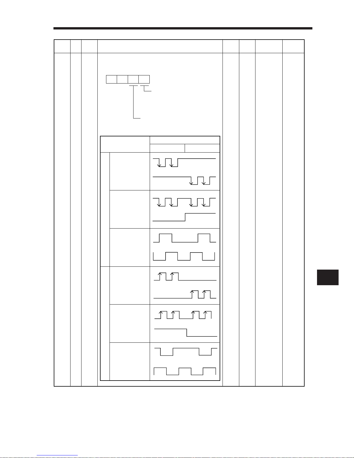
2. OPERATION
2
2– 41
21 *OP3 0000 0000h
to
0012h
P
Function selection 3 (Command pulse selection):
Used to select the input form of the pulse train input signal.
(Refer to Section 3-3 (1) 4).)
Command pulse train input form
0:
Forward/reverse rotation pulse train
1: Signed pulse train
2: A/B phase pulse train
Pulse train logic selection
0: Positive logic
1: Negative logic
00
Command Pulse
Train Form
Forward rotation
Reverse rotation
Forward rotation
pulse train
Reverse rotation
pulse train
(Set value 0010)
Pulse train
positive sign
(Set value 0011)
A-phase pulse train
B-phase pulse train
(Set value 0012)
Negative logic
Positive logic
Input Waveform
Class No.
Symbol
Initial
Value
Unit
Setting
Range
Control
Mode
Name and Function
Expansion parameters
Forward rotation
pulse train
Reverse rotation
pulse train
(Set value 0000)
Pulse train
positive sign
(Set value 0001)
A-phase pulse train
B-phase pulse train
(Set value 0002)
Page 72
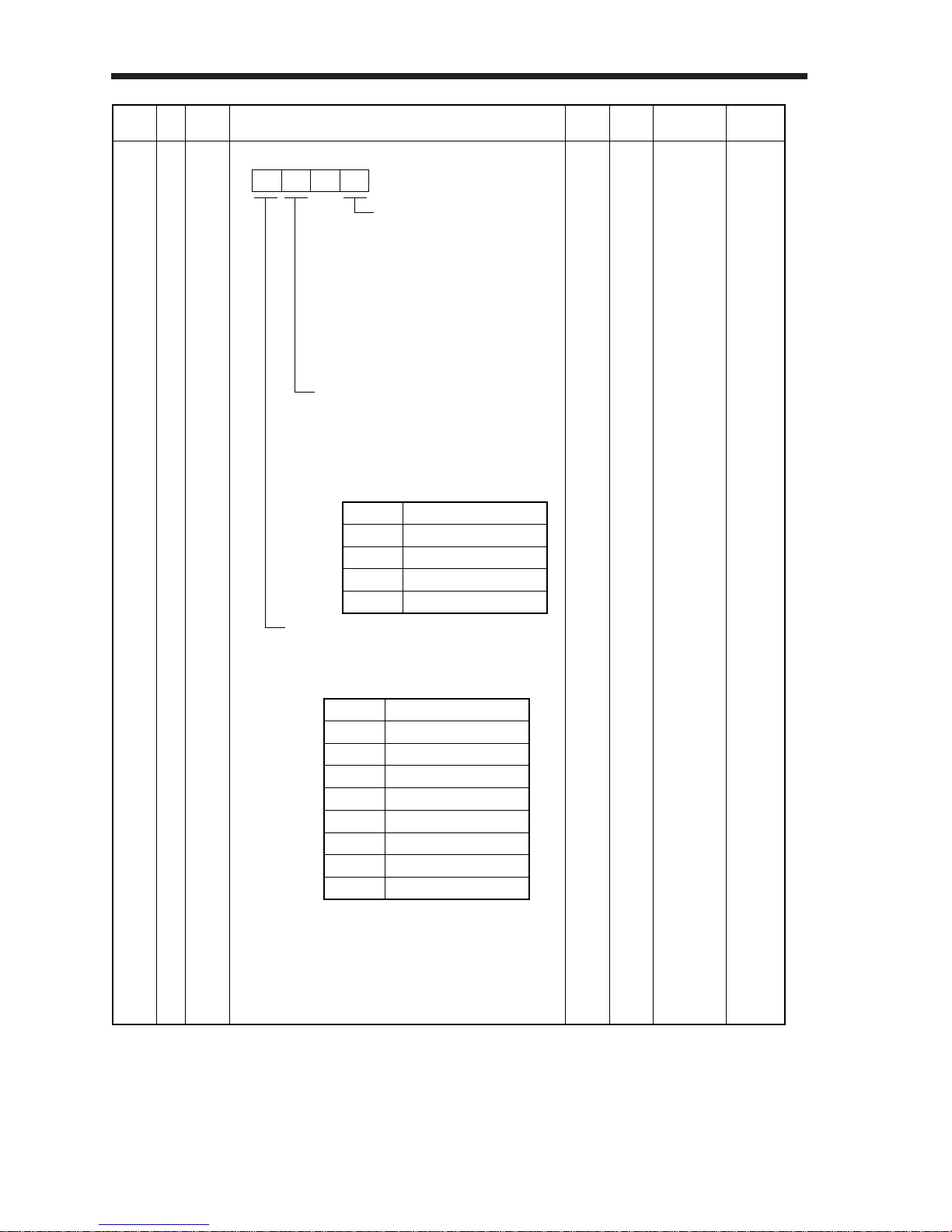
2. OPERATION
2– 42
22 *OP4 0000 0000h
to
7301h
P • S • T
Function selection 4:
Selection of servo motor stop
pattern at LSP/LSN signal off
0: Sudden stop
1: Slow stop
•
In the position control mode,
the servo motor is decelerated
to a stop according to parameter
No. 7 setting.
• In the speed control mode,
the servo motor is decelerated
to a stop according to parameter
No. 12 setting.
0
VC/VLA voltage averaging
Used to set the filtering time when the
analog speed command (VC) voltage or
analog speed limit (VLA) is imported.
Set 0 to vary the speed to voltage fluctua
tion in real time. Increase the set value
to vary the speed slower to voltage fluctuation.
Set Value Filtering Time [ms]
00
1 1.77
2 3.55
3 7.11
Machine resonance suppression filter
Used to set the frequency that matches the
resonance frequency of the mechanical system. (Refer to Section 2-4-2.)
Set value Notch Frequency [Hz]
0 Not used
1 1125
2 563
3 375
4 282
5 225
6 188
7 161
Class No.
Symbol
Initial
Value
Unit
Setting
Range
Control
Mode
Name and Function
Expansion parameters
Page 73
2. OPERATION
2
2– 43
26
TLC
Analog torque command maximum output:
Used to set the output torque at the analog torque
command voltage (TC=±8V) of +8V on the assumption
that the maximum torque is 100[%]. For example, set
50 to output (maximum torque x 50/100) at the TC of
+8V.
100
0 to 1000
T
%
27
*ENR
Encoder output pulses:
Used to set the number of output pulses per encoder
revolution output by the servo amplifier.
4000
5 to 16384
P •S •T
pulse
28
TL1
Internal torque limit 1:
Set this parameter to limit servo motor-generated torque
on the assumption that the maximum torque is 100[%].
When 0 is set, torque is not produced.
When analog monitor output is used to output torque,
this set value is the maximum output voltage (+8V).
100
0 to 100
T
%
Internal torque limit 1:
Set this parameter to limit servo motor-generated torque
on the assumption that the maximum torque is 100[%].
When 0 is set, torque is not produced.
P • S
Across TL-SG
Torque Limit
Internal torque limit 1 (Parameter No. 28)
Torque limit relationship
Analog torque limit < internal torque limit 1
Analog torque limit > internal torque limit 1
Valid torque limit
Analog torque limit
Internal torque limit 1
23
FFC
Feed forward gain:
Used to set the feed forward gain in position control.
By setting 100% for constant-speed operation, droop
pulses will not be generated. Note that sudden acceleration/deceleration will increase overshoot. (As a guideline, acceleration/deceleration time to/from rated speed
is 1s or longer when the set value is 100.)
0
0 to 100
P
%
24
ZSP
Zero speed:
Used to set the output range of the zero speed signal (ZSP)
.
50
0 to 10000
P •S •T
r/min
When setting this parameter,
always set auto tuning to "No"
(parameter No. 2).
25
VCM
Analog speed command maximum speed:
Used to set the speed at the maximum input voltage
(10V) of the analog speed command (VC).
Set 0 to select the rated speed.
Analog speed limit maximum speed:
Used to set the speed at the maximum input voltage
(10V) of the analog speed limit (VLA).
Set 0 to select the rated speed.
0
1 to 10000
S
T
r/min
MEMORANDUM
When analog monitor output is used to output torque, this
set value is the maximum output voltage (+8V).
0
0
0
1 to 10000
r/min
Class No.
Symbol
Initial
Value
Unit
Setting
Range
Control
Mode
Name and Function
Expansion parameters
Open
Short
Page 74
2. OPERATION
2– 44
29
VCO
Analog speed command offset:
Used to set the offset voltage of the analog speed
command (VC). When automatic VC offset is used, the
automatically offset value is set to this parameter.
The initial value is the value provided by the automatic VC
offset function before shipment at the VC-SG voltage of 0V.
Depends
on servo
amplifier.
—999 to 999
S
mV
Analog speed limit offset:
Used to set the offset voltage of the analog speed limit
(VLA). When automatic VC offset is used, the automatically offset value is set to this parameter.
The initial value is the value provided by the automatic VC
offset function before shipment at the VLA-SG voltage of 0V.
T
30
TLO
Analog torque command offset:
Used to set the offset voltage of the analog torque
command (TC).
0
—999 to 999
T
mV
Analog torque limit offset:
Used to set the offset voltage of the analog torque limit
(TLA).
S
31
MO1
Analog monitor 1 offset:
Used to set the offset voltage of the analog monitor 1
output (MO1).
0
—999 to 999
P • S • T
mV
32
MO2
Analog monitor 2 offset:
Used to set the offset voltage of the analog monitor 2
output (MO2).
0
—999 to 999
mV
33
MBR
Electromagnetic brake sequence output:
Used to set the delay time between when the electromagnetic brake interlock signal (MBR) switches off and
when the base circuit is shut off.
100
0
to
1000
ms
P • S • T
34
GD2
Ratio of load inertia moment to servo motor inertia moment:
Used to set the ratio of the load inertia moment to
the servo motor inertia moment. Note that when auto
tuning is selected, the result of auto tuning is automatically set.
70
0 to 1000
0.1
times
P • S • T
35
PG2
Position loop gain 2:
Used to set the gain of the position loop.
Set this parameter to increase position response to
load disturbance. Higher setting increases the response
level but is liable to generate vibration and/or noise.
30
1
to
500
rad/s
P
36
VG1
Speed loop gain 1:
Normally this parameter setting need not be changed.
Higher setting increases the response level but is liable
to generate vibration and/or noise.
216
20
to
5000
rad/s
P • S
37
VG2
Speed loop gain 2:
Set this parameter when vibration occurs on machines of
low rigidity or large backlash. Higher setting increases the
response level but is liable to generate vibration and/or noise
.
714
20
to
8000
rad/s
P • S
Class No.
Symbol
Initial
Value
Unit
Setting
Range
Control
Mode
Name and Function
Expansion parameters
Page 75
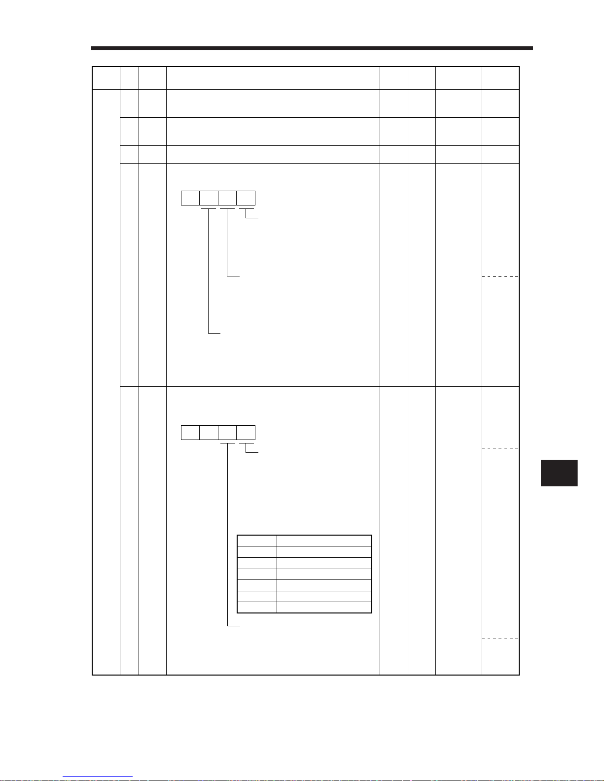
2. OPERATION
2
2– 45
42 *DI1 Input signal selection 1:
Used to assign the control mode changing signal input
pins and to set the clear signal.
0003 0000h
to
0015h
Control change signal (LOP) input pin assignment
Used to set the control mode
change signal input connector
pins. Note that this parameter is
made valid when parameter No.
0 is set to select the position/speed, speed/torque or torque/position change mode.
P/S
S/T
T/P
P • S • T
Set Value
0
1
2
3
4
5
Connector Pin No.
CN1B – 5
CN1B – 14
CN1A – 8
CN1B – 7
CN1B – 8
CN1B – 9
41 *DIA Input signal automatic ON selection:
Used to set automatic ON of SON, LSP and LSN.
0000 0000h
to
0111h
P • S • T
Servo on signal (SON) input selection
0: Switched on/off by external input.
1:
Switched on automatically in servo:
amplifier.
(No need of external wiring)
Forward rotation stroke end signal
(LSP) input selection
0: Switched on/off by external input.
1:
Switched on automatically in servo
amplifier.
(No need of external wiring)
Reverse rotation stroke end signal (LSN)
input selection
0: Switched on/off by external input.
1: Switched on automatically in servo
amplifier.
(No need of external wiring)
P • S
Clear signal (CR) selection
0: Droop pulses are cleared on the
leading edge.
1: Always cleared while on.
0
0
0
38
VIC
Speed integral compensation
Used to set the constant of integral compensation.
20
1 to 1000
P • S
P • S
ms
39
VDC
Speed differential compensation:
Used to set the differential compensation value.
40
Spare
980
0 to 1000
Class No.
Symbol
Initial
Value
Unit
Setting
Range
Control
Mode
Name and Function
Expansion parameters
Page 76
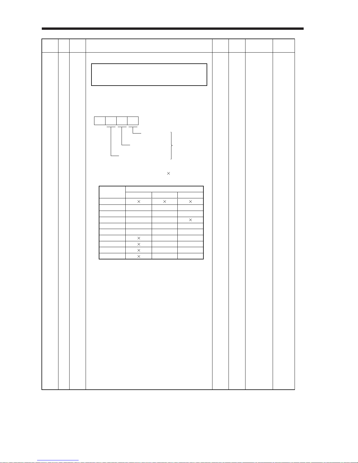
2. OPERATION
2– 46
Position
control mode
Torque control mode
Speed control
mode
43 *DI2 Input signal selection 2 (CN1B-pin 5): 0111 0000h
to
0999h
P • S • T
Input signals of
CN1B-pin 5
selected.
0
Set Value
(Note) Control Mode
PST
0
1
2
3
4
5
6
7
8
9
SON
RES
PC
TL
CR
SON
RES
PC
TL
CR
SP1
SP2
ST1
ST2
SON
RES
TL
CR
SP1
SP2
RS2
RS1
Note: P: Position control mode
S: Speed control mode
T: Torque control mode
Signals that may be assigned in each control mode are
indicated below by their symbols. indicates invalid
setting.
Allows any input signal to be assigned to CN1B-pin 5.
Note that the setting digit and assigned signal differ
according to the control mode.
This parameter is unavailable
when parameter No. 42 is set to
assign the control change signal
(LOP) to CN 1B-pin 5.
MEMORANDUM
Class No.
Symbol
Initial
Value
Unit
Setting
Range
Control
Mode
Name and Function
Expansion parameters
Page 77
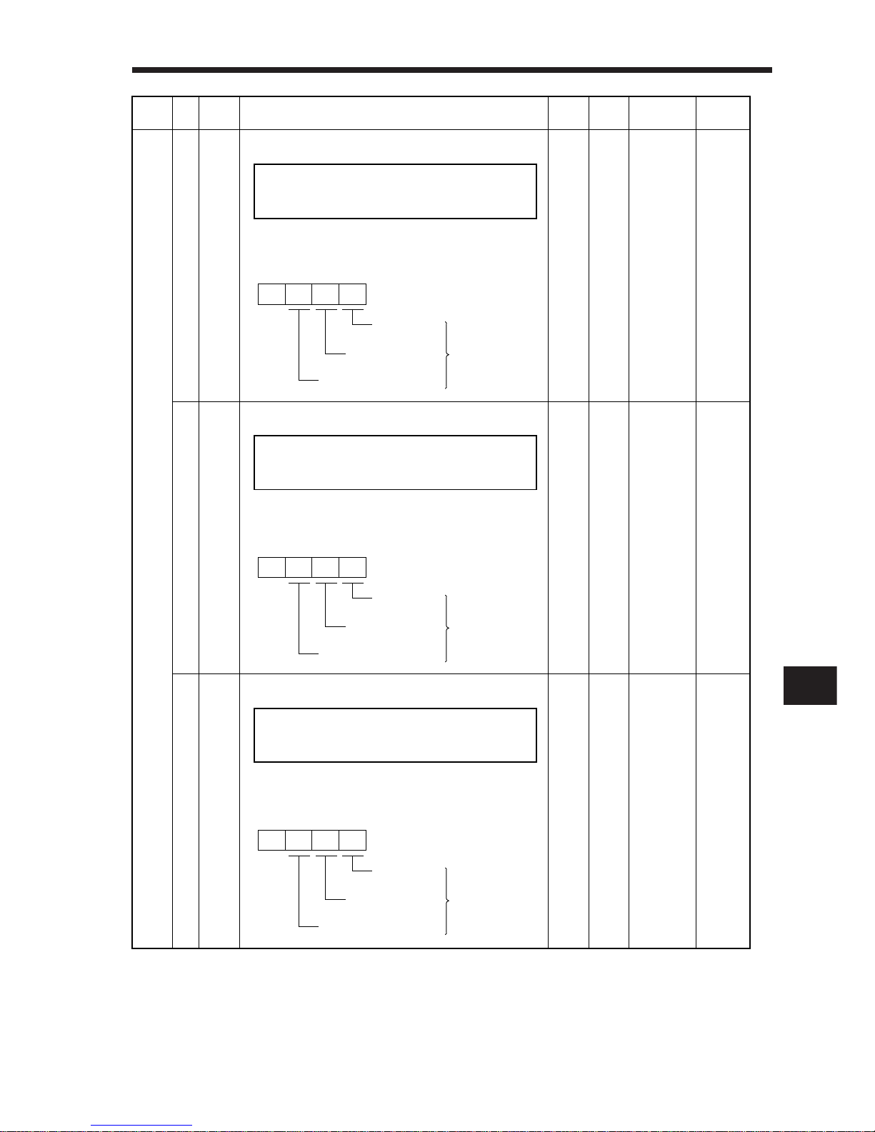
2. OPERATION
2
2– 47
44 *DI3 Input signal selection 3 (CN1B-pin 14): 0222 0000h
to
0999h
P • S • T
45 *DI4 Input signal selection 4 (CN1A-pin 8): 0665 0000h
to
0999h
P • S • T
46 *DI5 Input signal selection 5 (CN1B-pin 7): 0770 0000h
to
0999h
P •S •T
Allows any input signal to be assigned to CN1B-pin 14.
The assignable signals and setting method are the
same as in input signal selection 2 (parameter No. 43).
Allows any input signal to be assigned to CN1A-pin 8.
The assignable signals and setting method are the
same as in input signal selection 2 (parameter No. 43).
Allows any input signal to be assigned to CN1B-pin 7.
The assignable signals and setting method are the
same as in input signal selection 2 (parameter No. 43).
Class No.
Symbol
Initial
Value
Unit
Setting
Range
Control
Mode
Name and Function
Expansion parameters
Position
control mode
Torque control mode
Speed control
mode
Input signals of
CN1B-pin 14
selected.
0
This parameter is unavailable
when
parameter No. 42 is set to
assign the
control change signal
(LOP) to CN1 A-pin 8.
MEMORANDUM
This parameter is unavailable
when
parameter No. 42 is set to
assign the
control change signal
(LOP) to CN1B-pin 14.
MEMORANDUM
MEMORANDUM
Position
control mode
Torque control mode
Speed control
mode
Input signals of
CN1A-pin 8
selected.
0
This parameter is unavailable
when
parameter No. 42 is set to
assign the
control change signal
(LOP) to CN1 B-pin 7.
Position
control mode
Torque control mode
Speed control
mode
Input signals of
CN1B-pin 7
selected.
0
Page 78
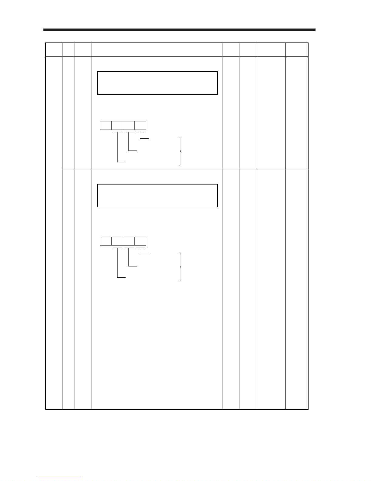
2. OPERATION
2– 48
47 *DI6 Input signal selection 6 (CN1B-pin 8): 0883 0000h
to
0999h
P •S •T
48 *DI7 Input signal selection 7 (CN1B-pin 9): 0994 0000h
to
0999h
P •S •T
Allows any input signal to be assigned to CN1B-pin 8.
The assignable signals and setting method are the
same as in input signal selection 2 (parameter No. 43).
Allows any input signal to be assigned to CN1B-pin 9.
The assignable signals and setting method are the
same as in input signal selection 2 (parameter No. 43).
Class No.
Symbol
Initial
Value
Unit
Setting
Range
Control
Mode
Name and Function
Expansion parameters
This parameter is unavailable
when
parameter No. 42 is set to
assign the
control change signal
(LOP) to CN1B-pin 8.
MEMORANDUM
Position
control mode
Torque control mode
Speed control
mode
Input signals of
CN1B-pin 8
selected.
0
Position
control mode
Torque control mode
Speed control
mode
Input signals of
CN1B-pin 9
selected.
0
This parameter is unavailable
when
parameter No. 42 is set to
assign the
control change signal
(LOP) to CN1B-pin 9.
MEMORANDUM
Page 79
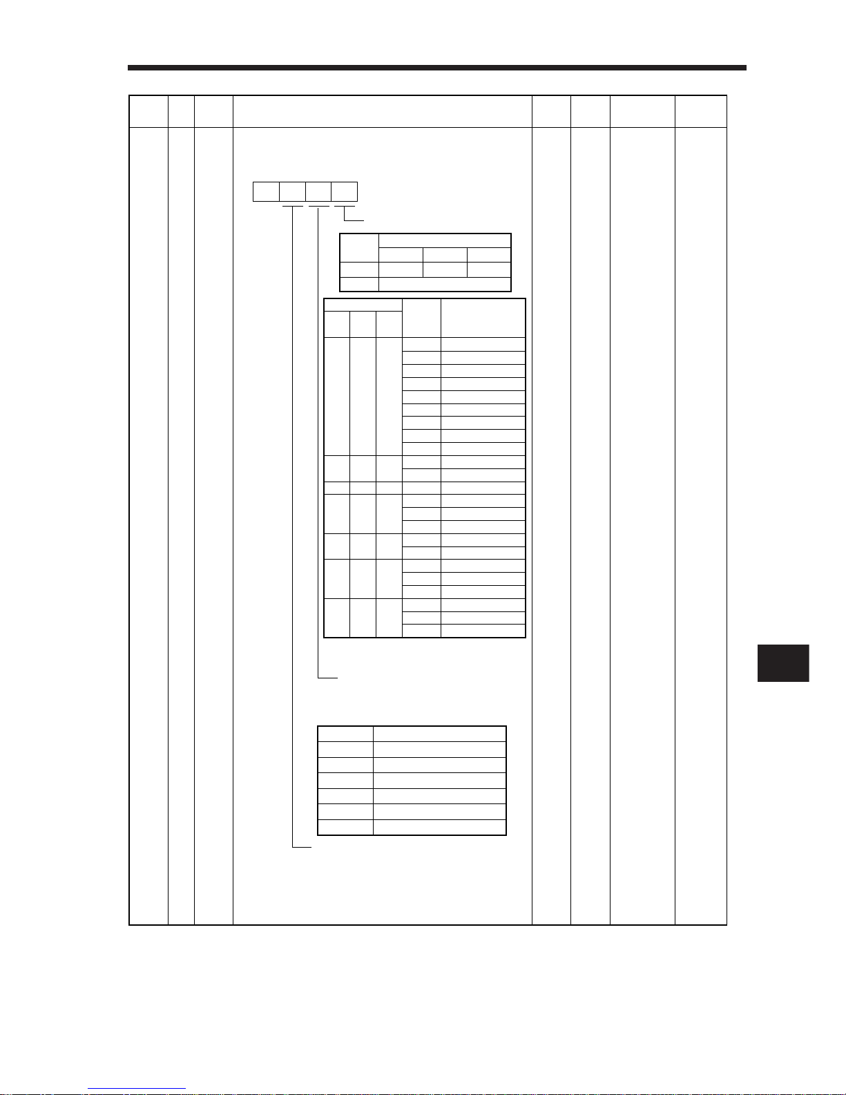
2. OPERATION
2
2– 49
49 *DO1 Output signal selection 1:
Used to select the connector pins to output the alarm
code, warning (WNG) and battery warning (BWNG).
Setting of alarm code output
Setting of battery warning (BWNG) output
Select the connector pin to output battery
warning. The old signal before selection
will be unavailable.
Set this function as in the second digit of
this parameter.
Setting of warning (WNG) output
Select the connector pin to output
warning. The old signal before
selection will be unavailable.
0000 0000h
to
0551h
P •S •T
Set Value
0
1
Connector Pins
CN1A-19
RD
CN1A-18
INP or SA
CN1B-19
ZSP
Alarm code is output at alarm occurrence.
(Note) Alarm Code
CN1B
pin 19
0
0
0
0
1
1
1
CN1A
pin 18
0
0
1
1
0
0
1
CN1A
pin 19
0
1
0
1
0
1
0
Alarm
Display
8888
A. 11
A. 12
A. 13
A. 15
A. 17
A. 18
A. 37
A. 8E
A. 30
A. 33
A. 10
A. 46
A. 50
A. 51
A. 24
A. 32
A. 31
A. 35
A. 52
A. 16
A. 20
A. 25
Name
Watchdog
Board error 1
Memory error 1
Clock error
Memory error 2
Board error 2
Board error 3
Parameter error
RS-232C error
Regenerative fault
Overvoltage
Undervoltage
Motor overheat
Overload 1
Overload 2
Ground fault
Overcurrent
Overspeed
Command pulse fault
Error excessive
Encoder error 1
Encoder error 2
Absolute position erasure
Set Value
0
1
2
3
4
5
Connector Pin No.
Not output.
CN1A-19
CN1B-18
CN1A-18
CN1B-19
CN1B-6
0
Note: 0:OFF
1:ON
Class No.
Symbol
Initial
Value
Unit
Setting
Range
Control
Mode
Name and Function
Expansion parameters
Page 80
2. OPERATION
2– 50
2-4 Adjustments
2-4-1 Auto tuning
Note: Settling time indicates a period of time from when the command pulse value is
zeroed to when the servo motor comes to a stop.
2-4-2 Manual gain adjustment
In general machines, gains are automatically adjusted by auto tuning. As the corresponding parameter is factory-set to make auto tuning valid, merely running the servo motor will automatically
set the optimum gains for the machine without special operation or setting.
However, if you are not satisfied with machine motions during operation, change and adjust the
response level setting (parameter No. 2) of auto tuning in the following procedure.
In most machines, gains can be adjusted automatically by auto tuning.
In the following cases, however, the gains should be adjusted manually.
Manual Gain Adjustment Is Required When Phenomenon Adjustment Procedure
1)
2)
3)
4)
The servo motor shaft vibrates at a high
frequency (10Hz or more)
a. When the machine generates large noise
and vibrates, the motion of the servo
motor shaft is invisible.
b. When the response level setting is
increased by auto tuning, vibration
increases.
The servo motor shaft vibrates at a low
frequency (5Hz or less).
a. When vibration occurs, the lateral vibration
of the servo motor shaft is visible.
b. The ratio of load inertia moment to servo
motor inertia moment is extremely large.
Adjustment 1
Adjustment 2
Adjustment 3
Adjustment 4
Adjustment 5
The machine vibrates at a low-range
resonance frequency.
The servo motor vibrates on a machine
whose ratio of load inertia moment to
servo motor inertia moment is 20 or more
times.
The settling time provided by auto tuning
should be further decreased.
The position control gain of each axis
should be set to the same for
interpolation operation with two or more
axes.
Gear noise is generated from the machine.
Smaller gear noise Decrease the set value of the response level.
Actual Machine Motion
Settling time is long (Note)
Overshoot occurs at a stop.
Ideal Machine Motion
Shorter settling time
Less overshoot
Parameter No. 2 Setting Method
Increase the set value of the response level.
Decrease the set value of the response level.
Select "large friction" in machine selection.
Page 81
2. OPERATION
2
2– 51
The following parameters are used for manual gain adjustment. Note that 000C should be set in
parameter No. 19 (parameter write disable) to make the expansion parameters valid.
Adjustment 1
Parameter No.
No. 2
No.34
No.22
No.6
No.35
No.36
No.37
No.38
Name
Auto tuning
Ratio of load inertia moment to servo motor inertia moment
Function selection 4 (Machine resonance suppression filter)
Position loop gain 1
Position loop gain 2
Speed loop gain 1
Speed loop gain 2
Speed integral compensation
Step
1
2
3
4
5
Operation Description
Set 0101 in parameter No. 2.
Set 1 in parameter No. 22.
Switch servo on and perform operation several
times.
Increase the setting of the fourth digit in
parameter No. 22 sequentially and execute step 3.
To reduce the settling time, increase the
response level of parameter No. 2 sequentially
and execute steps 2 to 4.
Auto tuning is selected.
Response is set to low level.
Machine resonance frequency: 1125Hz
Auto tuning is performed.
Check to see if vibration reduced.
The optimum value is achieved just before
vibration begins to increase.
Page 82
2. OPERATION
2– 52
Adjustment 2
Adjustment 3
Step Operation Description
Set 0101 in parameter No. 2.
Set the machine's load inertia moment to servo
motor inertia moment in parameter No. 34.
(When it is unclear, set an approximate value.)
Set 2 in parameter No. 2.
In parameter No. 37, set a value about 100
smaller than the value set automatically in step 3.
Execute steps 2 to 4 of Adjustment 1.
When machine response does not occur any
more, confirm the operating status, and at the
same time, gradually increase the setting of
parameter No. 37 reduced in step 4.
To reduce the settling time, increase the
response level of parameter No. 2 sequentially
and execute steps 1 to 6.
Auto tuning is selected.
Response is set to low level.
When this parameter value is set, the following
parameter values are set automatically. Each value
provides an ideal, hunting-less gain for parameter
No. 34 if machine resonance does not occur.
• Parameter No. 6
• Parameter No. 35
• Parameter No. 36
• Parameter No. 37
• Parameter No. 38
Auto tuning is made invalid to enable manual
setting of parameters No. 6 • 35 to 38.
The optimum value is achieved just before
vibration begins to increase.
Set a value which is about 50 to 100 smaller than
the set value at which gear noise and/or vibration
begins to be generated by machine resonance.
2
3
4
5
6
7
1
Operation DescriptionStep
Set 0101 in parameter No. 2.
Set the machine's load inertia moment to servo
motor inertia moment in parameter No. 34.
(When it is unclear, set an approximate value.)
Switch servo on and perform operation several
If vibration still persists, execute steps 2 and 3.
If vibration occurs due to machine resonance,
make adjustment in the
procedure of Adjustment 1 or 2.
Auto tuning is selected.
Response is set to low level.
When this parameter value is set, the following
parameter values are set automatically. Each
value provides an ideal, hunting-less gain for
parameter No. 34 if machine resonance does
not occur.
• Parameter No. 6
• Parameter No. 35
• Parameter No. 36
• Parameter No. 37
• Parameter No. 38
Auto tuning is performed.
1
2
3
4
5
Page 83
2. OPERATION
2
2– 53
Adjustment 4
Adjustment 5
Operation DescriptionStep
Set 0101 in parameter No. 2.
Switch servo on and perform operation several
times.
Make gain adjustment in either of the following
methods 1) and 2).
1) Set the machine's load inertia moment to
servo motor inertia moment in parameter No.
34. (When it is unclear, set an approximate
value.)
2) Switch servo on and perform operation
Set 2 in parameter No. 2.
While confirming the operating status, adjust
the following parameters:
• Parameter No. 36
• Parameter No. 37
• Parameter No. 38
Auto tuning is selected.
Response is set to low level.
Auto tuning is performed.
Check to see if vibration reduced.
Temporary adjustment
When this parameter value is set, the following
parameter values are
set automatically. Each value provides an
ideal, hunting-less gain for
parameter No. 34 if machine resonance does
not occur.
• Parameter No. 6
• Parameter No. 35
• Parameter No. 36
• Parameter No. 37
• Parameter No. 38
Auto tuning is performed.
Auto tuning is made invalid to enable manual
setting of parameters No. 6 • 35 to 38.
The optimum value is achieved just before
vibration begins to increase.
Increase the setting to improve servo response.
Note that vibration is more liable to occur.
Decrease the setting to keep the speed
constant to load disturbance and increase
holding force at a stop (servo rigidity). Note that
overshoot
• Parameter No. 6
• Parameter No. 35
Increase the setting to reduce the settling time.
Note that overshoot is more liable to occur.
1
2
3
4
5
Set the following parameter of each axis to the
minimum value of all interpolation-controlled
axes: • Parameter No. 6
Step Operation Description
Adjust the gains of all axes in any of
Adjustment 1 to 4 procedures.The gains of each
axis are adjusted.
Set 0 or 2 in parameter No. 2.
The gains of each axis are adjusted.
The gains for operation of all axes are set to the
same value.
1
2
3
2
0
"no": Auto tuning is made invalid to
enable manual setting of parameters
No. 6 • 35 to 38.
"interpolation axis control": The values
of parameters No. 34 • 35 • 37 • 38
will change in subsequent operation.
Page 84

2. OPERATION
2– 54
2-4-3 Slight vibration suppression control
The slight vibration suppression control mode is used to reduce servo-specific ±1 pulse vibration at
the time of a stop. This mode produces an effect especially when the ratio of load inertia moment to
servo motor inertia moment is small (2 to 5 times). Note that when vibration is attributable to looseness (such as gear backlash) or machine resonance, use the machine resonance suppression filter
in parameter No. 22. The slight vibration suppression control mode should be used after real-time
auto tuning or manual gain adjustment.
Usage
First, perform real-time auto tuning or manual gain adjustment so that vibration falls within ±2 to 3
pulses.
Set 1 in parameter No. 20 to enter the slight vibration suppression mode at the time of a
stop.
Slight vibration suppression
control execution
Parameter No. 20
1
Page 85
3– 1
CHAPTER 2
CHAPTER 3
CHAPTER 4
CHAPTER 5
CHAPTER 6
CHAPTER 7
CHAPTER 8
CHAPTER 9
CHAPTER 10
CHAPTER 11
INTRODUCTION
OPERATION
WIRING
INSTALLATION
ABSOLUTE POSITION DETECTION SYSTEM
OPTIONS AND AUXILIARY EQUIPMENT
INSPECTION
TROUBLESHOOTING
CHARACTERISTICS
SPECIFICATIONS
SELECTION
This chapter provides information required for wiring of connectors, terminals, etc. Before doing wiring
work, always read this chapter.
CHAPTER 1
CHAPTER 3
WIRING
3-1 Servo
3-1-1 Terminal blocks
3-1-2 Signal connectors
3-1-3 Detailed information on I/O signals
3-1-4 Interfaces
3-2 Connection of Servo Amplifier and Servo Motor
3-2-1 Connection instructions
3-2-2 Connection diagram
3-2-3 I/O terminals
3-2-4 Connectors used for Servo Motor wiring
3-3 Common Line
3-4 Grounding
3-5 Power Supply Circuit
3-6 Alarm Occurrence Timing Chart
3-7 Servo Motor with Electromagnetic Brake
Page 86
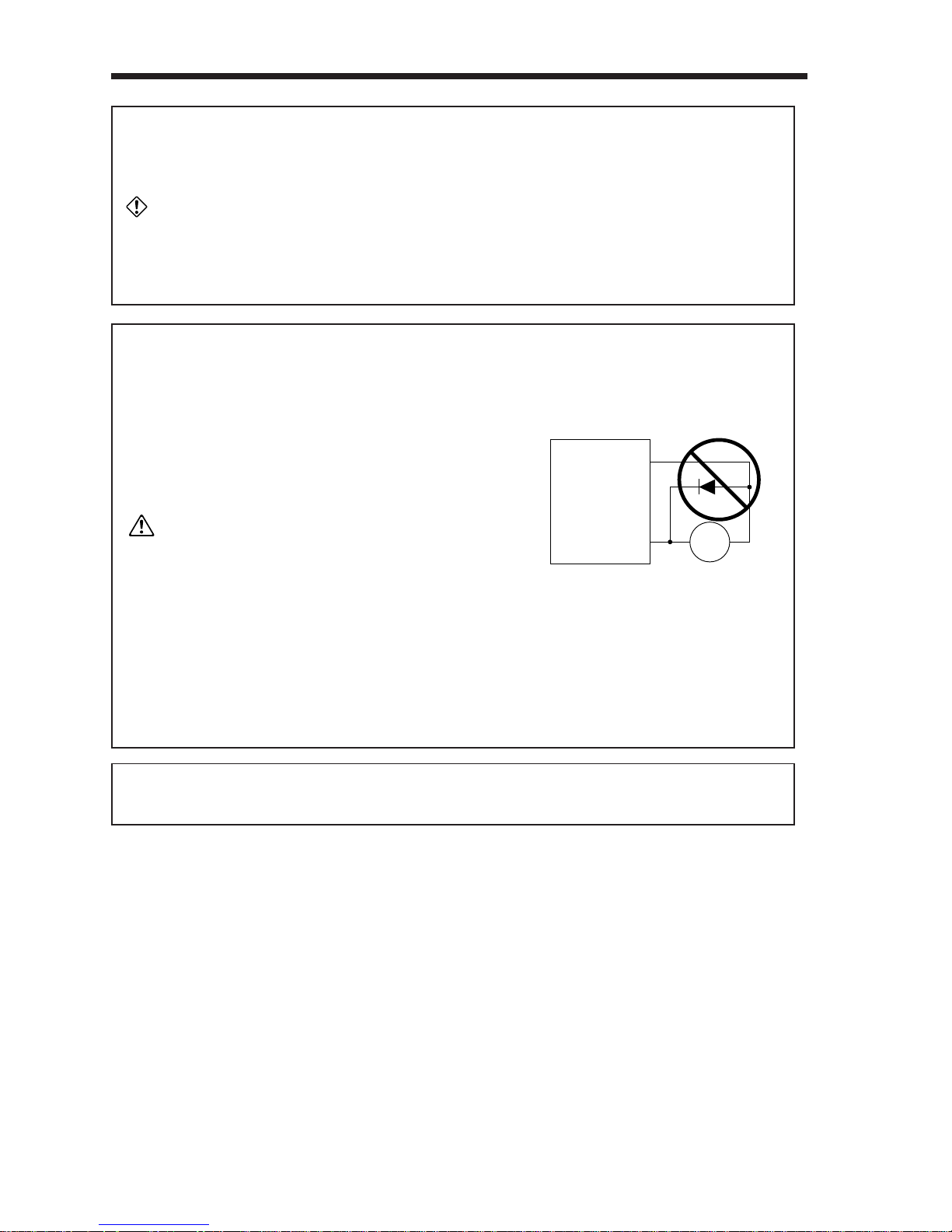
3– 2
3.WIRING
1. Any person who is involved in wiring should be fully competent to do
the work.
2. Before star ting wir ing, make sure that the voltage is safe in the tester
more than 10 minutes after power-off. Otherwise, you may get an
electric shock.
3. Ground the servo amplifier and the servo motor securely.
4. Do not attempt to wire the servo amplifier and servo motor until they
have been installed. Otherwise, you may get an electric shock.
5. The cables should not be damaged, stressed excessively, loaded
heavily, or pinched. Otherwise, you may get an electric shock.
CN1A, CN1B, CN2 and CN3 have the same shape. Wrong connection of the
connectors will lead to a failure. Connect them correctly.
1. Wire the equipment correctly and securely. Otherwise, the servo motor
may misoperate, resulting in injury.
2. Connect cables to correct ter minals to prevent a burst, fault, etc.
3. Ensure that polarity (+, -) is correct. Otherwise, a burst, damage,
etc. may occur.
4. The surge absorbing diode installed to the DC relay designed
for control output should be fitted in the specified direction.
Otherwise, the signal is not output due to a fault, disabling the
emergency stop and other protective circuits.
5. Use a noise filter, etc. to minimize the influence of electromagnetic interference, which may be
given to electronic equipment used near the servo amplifier.
6. Do not install a power capacitor, surge suppressor or radio noise
filter (FR-BIF option) with the power line of the servo motor.
7. When using the regenerative brake resistor, switch power off with
the alarm signal. Otherwise, a transistor fault or the like may
overheat the regenerative brake resistor, causing a fire.
8. Do not modify the equipment.
CAUTION
WARNING
NOTICE
RA
COM
(24VDC)
Control output
signal
Servo amplifier
Page 87
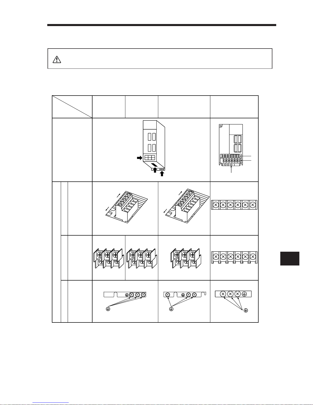
3– 3
3
3.WIRING
3-1-1 Terminal blocks
Only the specified voltage should be applied to each terminal. Otherwise, a
burst, damage, etc. may occur.
(1) Signal arrangement
Terminal block signals are as listed below:
Servo Amplifiers
Terminals
Terminal positions
MR–J2–10A
to
MR–J2–60A
MR–J2–10A1
to
MR–J2–40A1
MR–J2–70A
MR–J2–100A
MR–J2–200A
MR–J2–350A
1)
2)
3)
Control circuit
terminalblock
(TE2)
Main circuit
terminal block
(TE1)
Protective
earth(PE)
terminals
L1 L2 L3
UVW
L1 L2 L3
UVW
L1 L2
UVW
2)
3)
1)
Front
Rear
D
C
P
L
21
L
11
(Phoenix Contact make)
Front
D
C
P
L
21
L
11
N
Rear
(Phoenix Contact make)
L1 L2 L3 U V W
L11 L21 D P C N
3)
1)
2)
Terminal signals
3-1 Servo Amplifier
CAUTION
Page 88
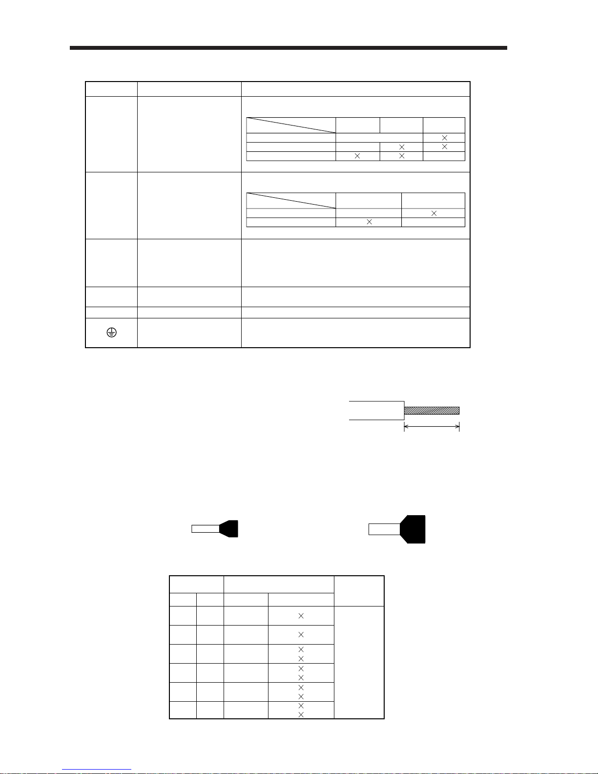
3– 4
3.WIRING
(2) Signals
(3) How to use the control circuit terminal block (Phoenix Contact make)
1) Ter mination of the cables
Solid wire: After the sheath has been stripped,
the cable can be used as it is. (Cable
size: 0.2 to 2.5mm2)
Twisted wire: Use the cable after stripping the sheath and twisting the core. At this
time, take care to avoid a short caused by the loose wires of the
core and the adjacent pole. Do not solder the core as it may cause a
contact fault. (Cable size: 0.2 to 2.5mm2)
Alternatively, a bar terminal may be used to put the wires together.
(Phoenix Contact make)
Approx. 10mm
Bar terminal for 1 cable
(Bar terminal ferrule with insulation sleeve)
Bar terminal for 2 cables
(Twin ferrule with insulation sleeve)
Symbol Signal Description
L1, L2, L3
Main circuit power supply
Main circuit power input terminals
Supply L1, L2 and L3 with the following power:
Servo amplifier
MR-J2-10A
to 70A
MR-J2-100A
to 350A
MR-J2-10A1
to 40A1
Power supply
Note: Cannot be used for combination with the servo motor HC-SF52.
L1•L2•L3
L1•L2
L1•L2
3-phase 200 to 230VAC, 50/60Hz
(Note) Single-phase 230VAC, 50/60Hz
Single-phase 100 to 120VAC, 50/60Hz
L11, L21
Control circuit power supply
Control circuit power input terminals
Supply L11 and L21 with the following power:
L11 and L21 should be in phase with L1 and L2, respectively.
P, C, D Regenerative brake option
U, V, W
Servo motor output
Servo motor power output terminals
Connect to the servo motor power supply terminals (U, V, W).
N
–
Do not connect.
Protective earth (PE)
Ground terminal
Connect this terminal to the protective earth (PE) terminals
of the servo motor and control box for grounding.
Regenerative brake option connection terminals
C and D are factory-connected.
When using the regenerative brake option, always remove
wiring from across P-D and connect the regenerative brake
option across P-C.
Servo amplifier
MR-J2-10A
to 350A
MR-J2-10A1
to 40A1
Power supply
L11•L21
L11•L21
Single-phase 200 to 230VAC, 50/60Hz
Single-phase 100 to 120VAC, 50/60Hz
Cable Size
Bar Terminal Type
Crimping
Tool
[mm ]
2
AWG
For 1 cable For 2 cables
0.25 24
20
18
18
16
14
0.5
0.75
1
1.5
2.5
Al0.25-6YE
Al0.25-8YE
Al-TWIN2 0.75-8GY
Al-TWIN2
0.75-10GY
Al-TWIN2 1-8RD
Al-TWIN2 1-10RD
Al-TWIN2 1.5-8BK
Al-TWIN2 1.5-12BK
Al-TWIN2 2.5-10BU
Al-TWIN2 2.5-13BU
Al0.5-6WH
Al0.5-8WH
Al0.75-6GY
Al0.75-8GY
Al1-6RD
Al1-8RD
Al1.5-6BK
Al1.5-8BK
Al2.5-8BU
Al2.5-8BU-1000
CRIMPFOX-UD6
Page 89
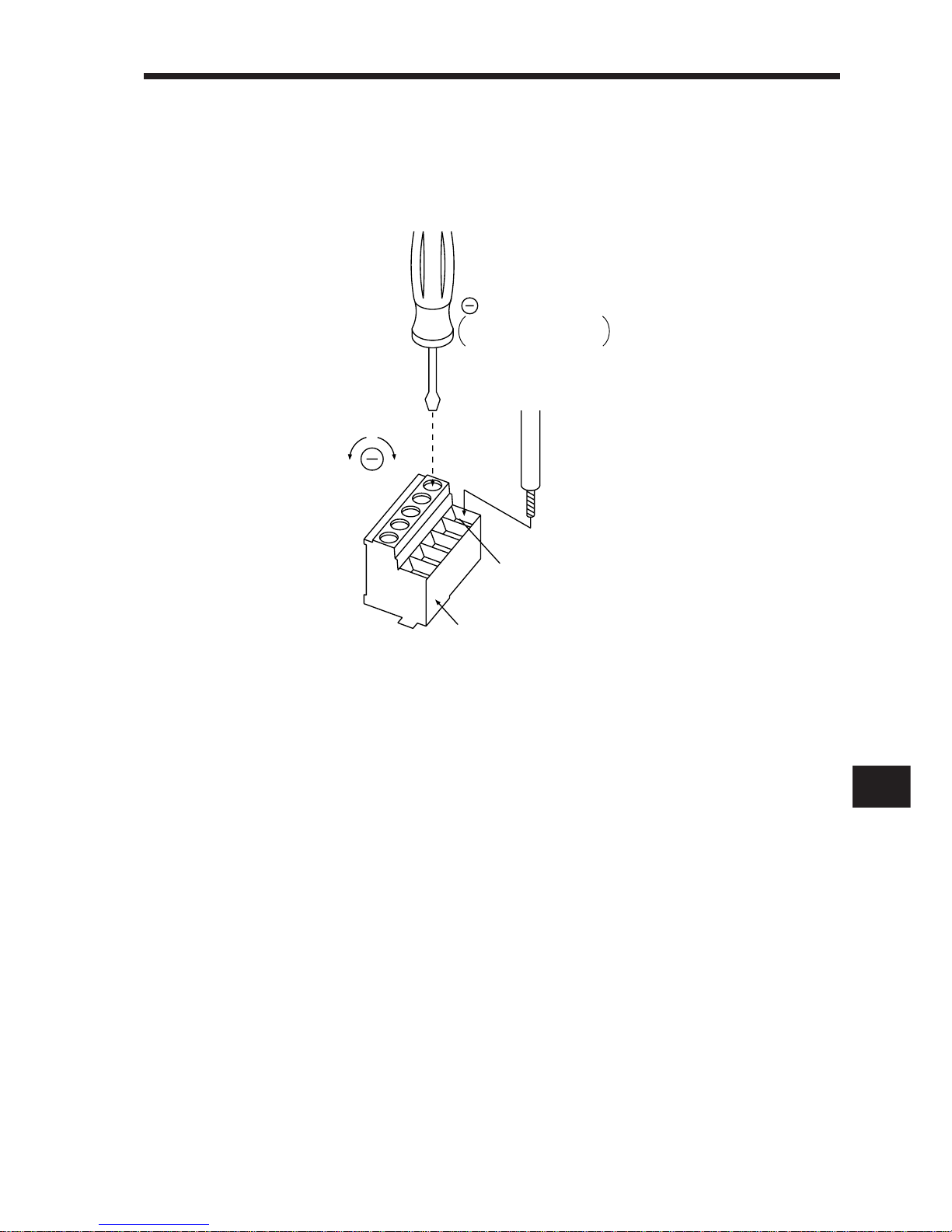
3– 5
3
3.WIRING
2) Connection
Insert the core of the cable into the opening and tighten the screw with a flat-blade
screwdriver so that the cable does not come off. (Tightening torque: 0.5 to 0.6N•m)
Before inserting the cable into the opening, make sure that the screw of the terminal
is fully loose.
When using a cable of 1.5mm2 or less, two cables may be inserted into one opening.
To loosen.
To tighten.
Opening
Control circuit terminal block
Cable
Flat-blade screwdriver
• Tip thickness 0.4 to 0.6mm
• Overall width 2.5 to 3.5mm
Page 90
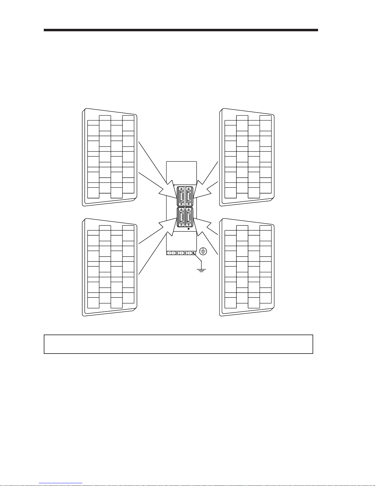
3– 6
3.WIRING
3-1-2 Signal connectors
CN1A
1
3
5
7
9
2
4
6
8
10
12
14
16
18
20
11
13
15
17
19
1
3
5
7
9
2
4
6
8
10
12
14
16
18
20
11
13
15
17
19
CN2
LG
LG
LG
LG
LG
MD MDR
MRRMR
P5
P5
P5
BAT
P5
CN1B
1
3
5
7
9
2
4
6
8
10
12
14
16
18
20
11
13
15
17
19
1
3
5
7
9
2
4
6
8
10
12
14
16
18
20
11
13
15
17
19
CN3
RXD
LG
TXD
LG
MO2
LG
MITSUBISHI
MELSERVO–J2
*The connector frames
are connected with the
PE terminal inside the
servo amplifier.
P5
LG
LG
MO1
LG
(1) Signal arrangement
All connectors are half-pitch connectors (Molex 52986-2011 or
equivalent).CN1A and CN1B signals change with the control mode. Refer to (2) in
this section.
MEMORANDUM
The connector pin-outs shown above are viewed from the cable connector
wiring section side.
Page 91
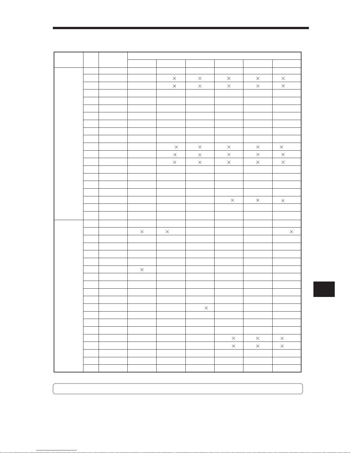
3– 7
3
3.WIRING
(2) CN1A and CN1B signal assignment
For notes, refer to the next page.
Connector
Pin No.
Signal Input/Output
(Note 1) I/O
P P/S S S/T T T/P
(Note 2) Symbols of I/O Signals in Control Modes
1 – LG LG LG LG LG LG
2 I NP NP/ /NP
3 I PP PP/ /PP
4 – P15R P15R/P15R P15R P15R P15R P15R
5 O LZ LZ LZ LZ LZ LZ
6 O LA LA LA LA LA LA
7 O LB LB LB LB LB LB
(Note 8)8
I CR CR/SP1
(Note 3)
SP1 SP1/SP1
(Note 3)
SP1 SP1/CR
9 – COM COM COM COM COM COM
10– SGSGSGSGSGSG
11 – OPC OPC/ /OPC
12 I NG NG/ /NG
13 I PG PG/ /PG
14O OPOPOPOPOPOP
15 O LZR LZR LZR LZR LZR LZR
16 O LAR LAR LAR LAR LAR LAR
17 O LBR LBR LBR LBR LBR LBR
(Note 7, 9)
18
O INP INP/SA SA SA/ /INP
(Note 7, 9)
19
O RDRDRDRDRDRD
20– SGSGSGSGSGSG
CN1A
1 – LG LG LG LG LG LG
2 I /VC VC VC/VLA VLA VLA/
3 – VDD VDD VDD VDD VDD VDD
(Note 10)
4
O DO1 DO1 DO1 DO1 DO1 DO1
(Note 8)5
I SON SON SON SON SON SON
(Note 7)6
O TLC TLC TLC TLC/VLC VLC VLC/TLC
(Note 8)7
I LOP SP2 LOP SP2 LOP
(Note 8)8
I PC PC/ST1
(Note 4)
ST1 ST1/RS2
(Note 4)
RS2 RS2/PC
(Note 8)9
I TL TL/ST2
(Note 5)
ST2 ST2/RS1
(Note 5)
RS1 RS1/TL
10– SGSGSGSGSGSG
11 – P15R P15R P15R P15R P15R P15R
12 I TLA
TLA/TLA(Note 6) (Note 6) (Note 6)TLA/TC
TC TC/TLA
13 – COM COM COM COM COM COM
(Note 8)
14
I RES RES RES RES RES RES
15 I EMG EMG EMG EMG EMG EMG
16 I LSP LSP LSP LSP/ /LSP
17 I LSN LSN LSN LSN/ /LSN
(Note 7)
18
O ALM ALM ALM ALM ALM ALM
(Note 7,
9, 11)19
O ZPS ZSP ZSP ZSP ZSP ZSP
20– SGSGSGSGSGSG
Pin assignment
CN1B
Page 92

3– 8
3.WIRING
Note: 1. I: Input signal, O: Output signal, -: Others (e.g. power)
2. P: Position control mode, S: Speed control mode, T: Torque control
mode, P/S: Position/speed control change mode, S/T: Speed/torque
control change mode, T/P: Torque/position control change mode
3. Set parameter No. 45 to use CR.
4. Set parameter No. 47 to use PC.
5. Set parameter No. 48 to use TL.
6. By setting parameters No. 43 to 48 to make TL available, TLA can be used.
7. Set parameter No. 49 to use WNG and BWNG.
8. Set parameters No. 43 to 48 to change signals.
9. Set parameter No. 49 to select alarm codes. (Refer to Chapter 8.)
10.The signal of CN1A-18 is always output.
11.Set parameter No. 1 to select MBR.
(3) Symbols and signal names
Symbol Symbol
Signal Name Signal Name
SON
LSP
LSN
CR
SP1
SP2
PC
ST1
ST2
TL
RES
EMG
LOP
VC
VLA
TLA
TC
RS1
RS2
PP
NP
PG
NG
TLC
VLC
RD
ZSP
INP
SA
ALM
WNG
BWNG
OP
MBR
LZ
LZR
LA
LAR
LB
LBR
MO1
MO2
VDD
COM
OPC
SG
P15R
LG
SD
Servo on
Forward rotation stroke end
Reverse rotation stroke end
Clear
Speed selection 1
Speed selection 2
Proportion control
Forward rotation start
Reverse rotation start
Torque limit
Reset
External emergency stop
Control change
Analog speed command
Analog speed limit
Analog torque limit
Analog torque command
Forward rotation selection
Reverse rotation selection
Forward/reverse rotation pulse train
Limiting torque
Limiting speed
Ready
Zero speed
In position
Speed reached
Trouble
Warning
Battery warning
Encoder Z-phase pulse (open collector)
Electromagnetic brake interlock
Encoder Z-phase pulse
(differential line driver)
Encoder A-phase pulse
(differential line driver)
Encoder B-phase pulse
(differential line driver)
Analog Monitor output 1
Analog Monitor output 2
I/F internal power supply
Digital I/F power supply input
Open collector power input
Digital I/F common
DC15V power supply
Control common
Shield
Page 93
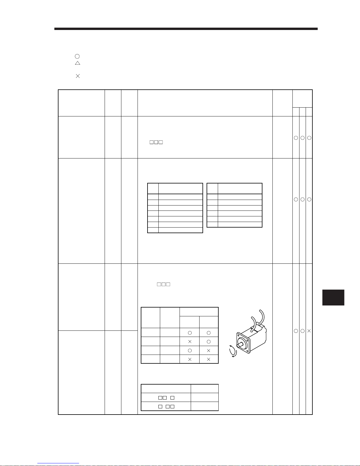
3– 9
3
3.WIRING
(4) Signal explanations
In the Control Mode field of the table
: Denotes that the signal may be used in the initial setting status.
: Denotes that the signal may be used by setting the corresponding parameter among
parameters No. 1 and 43 to 49.
: Denotes that the signal cannot be used.
1) Input signals
Signal
Symbol
Control
Mode
(Note 2)
PST
Functions/Applications
Servo on
I/O
Division
(Note 1)
SON CN1B5Connect SON-SG to switch on the base circuit and make
the servo amplifier ready to operate (servo on).
Disconnect SON-SG to shut off the base circuit (servo off)
andcoast the servo motor.
Set 1 in parameter No. 41 to switch this signal on
(keep terminals connected) automatically in the servo
amplifier.
DI–1
Reset RES CN1B14Disconnect RES-SG for more than 50ms to reset the alarm.
During alarm resetting, the base circuit is shut off.
The following alarms cannot be reset:
Also, the regenerative error (A. 30) and overload 1 (A. 50)
cannot be reset until the regenerative brake resistor and
power transistor are cooled to proper temperatures, respectively.
Connect RES-SG during operation to shut off the base circuit and
coast the servo motor to a stop.
DI–1
Forward rotation
stroke end
LSP CN1B16The forward and/or reverse rotation stroke end signal must
be ON to run the servo motor. If the signal is switched off,
the servo motor will stop suddenly and servo-locked. By
setting 1 in parameter No. 22, the servo motor will
come to a slow stop when the signal is switched off.
Relationships between signal status and operation are as
follows:
DI–1
Connector Pin
No.
Operation
Across
LSP-SG
Across
LSN-SG
Short Short
Open Short
Short Open
Open Open
CCW
directionCWdirection
Set parameter No. 41 as indicated below to switch on the signals
(keep terminals connected) automatically in the servo amplifier:
Parameter No. 41
Automatic ON
LSP
LSN
Reverse rotation
stroke end
LSN CN1B
17
CCW
CW
Board error 1
Memory error 1
Clock error
Memory error 2
Encoder error 1
Board error 2
Board error 3
Display
A. 11
A. 12
A. 13
A. 15
A. 16
A. 17
A. 18
Name
Encoder error 2
Absolute position erase
Regenerative error
Parameter error
Overload 1
Overload 2
Display
A. 20
A. 25
A. 30
A. 37
A. 50
A. 51
Name
Note: 1. Refer to Section 3-1-4.
2. P: Position control mode, S: Speed control mode, T: Torque control mode
Forward
rotation
Reverse rotation
1
1
Page 94
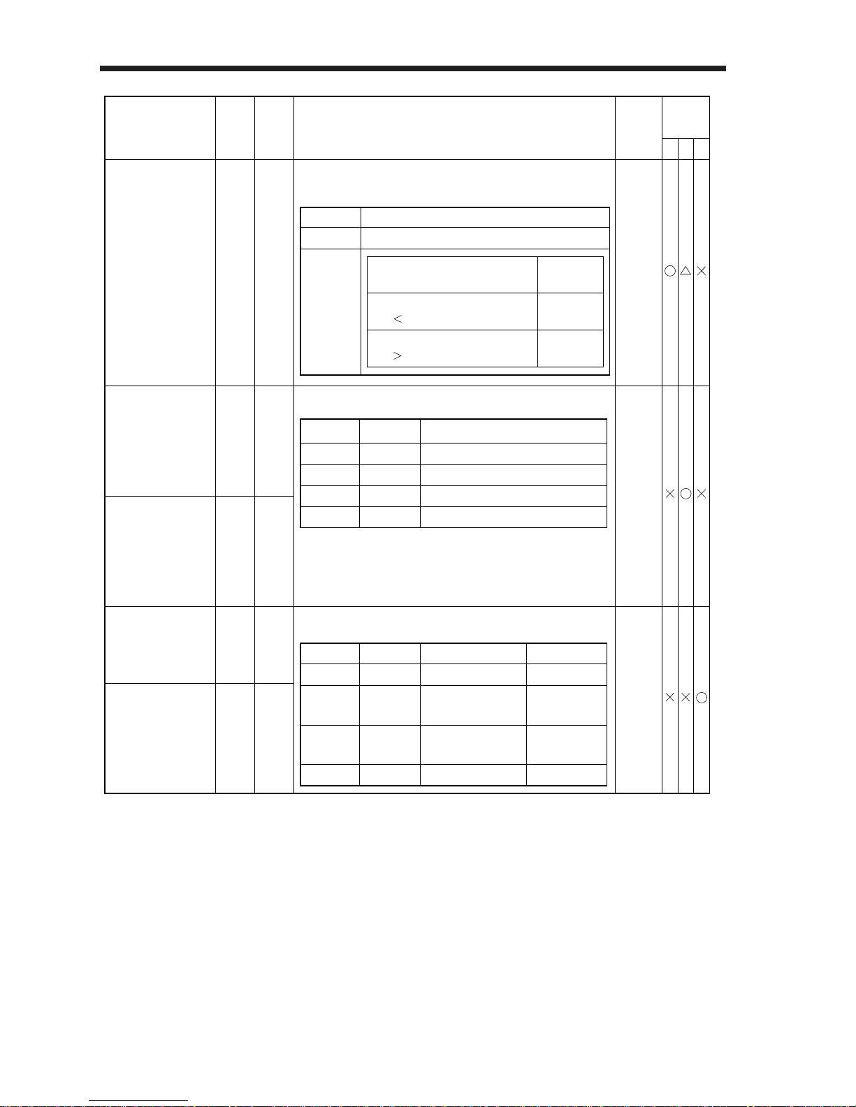
3– 10
3.WIRING
Signal
Symbol
Control
Mode
(Note 2)
PST
Functions/Applications
Torque limit
I/O
Division
(Note 1)
TL CN1B
9
DI–1
Connec-
tor Pin
No.
Torque limit relationship
Valid torque
limit
Connect TL-SG to limit torque according to the voltage
level (max. torque: +8V) of analog torque limit (TLA).
Across TL-SG
Open
Short
Torque Limit
Internal torque limit 1 (parameter No. 28)
Analog torque limit
internal torque limit 1
Analog torque
limit
Analog torque limit
internal torque limit 1
Internal torque
limit 1
DI–1Forward rotation
start
ST1 CN1B8Used to start the servo motor in any of the following directions:
Stop (servo lock)
CCW
CW
Stop (servo lock)
Open
Short
Open
Short
Open
Open
Short
Short
Reverse rotation
start
ST2 CN1B
9
If both ST1 and ST2 are switched on or off during operation,
the servo motor will be decelerated to a stop according to
the parameter No. 12 setting and servo-locked. When the
analog speed command (VC) is 0V, starting the servo motor
will not generate servo lock torque.
Forward rotation
selection
RS1 CN1B9Used to select any of the following servo motor torque
generation directions:
DI–1
Torque Generation DirectionAcross RS1-SG Across RS2-SG
Reverse rotation
selection
RS2 CN1B
8
Rotation Direction
Note: 1. Refer to Section 3-1-4.
2. P: Position control mode, S: Speed control mode, T: Torque control
Forward rotation in driving
mode / reverse rotation in
regenerative mode
Reverse rotation in driving
mode / forward rotation in
regenerative mode
Across
ST1-SG
Across
ST2-SG
Servo Motor Starting Direction
Open
Short
Open
Short
Open
Open
Short
Short
No torque
No torque
Stop
CCW
CW
Stop
Page 95
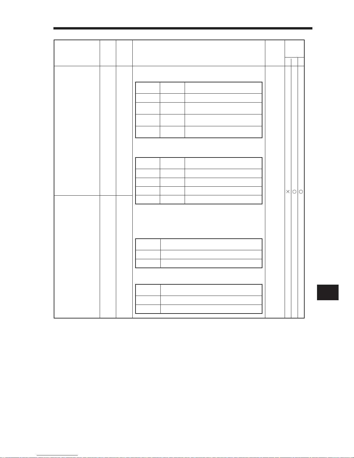
3– 11
3
3.WIRING
Signal
Symbol
Control
Mode
(Note 2)
PST
Functions/Applications
I/O
Division
(Note 1)
Connec-
tor Pin
No.
Speed selection 1 SP1 CN1A8<Speed control mode>
Used to select the command speed for operation.
Analog speed command (VC)
Open
Speed selection 2 SP2 CN1B
7
Analog speed command (VC)
Internal speed command 1 (parameter No. 8)
Open
Short
<Torque control mode>
Used to select the limit speed for operation.
<Position/speed, speed/torque, torque/position control change mode>
As CN1B-7 acts as a control change signal, the speed
selected when the speed or torque control mode is selected
is as follows:
• When speed control mode is selected
• When torque control mode is selected
DI–1
Internal speed command 1
(parameter No. 8)
Analog speed limit (VLA)Open
Short
Open
Short
Open
Open
Short
Short
Internal speed limit 1 (parameter No. 8)
Internal speed limit 2 (parameter No. 9)
Internal speed limit 3 (parameter No. 10)
Analog speed limit (VLA)
Internal speed limit 1 (parameter No. 8)
Open
Short
Note: 1. Refer to Section 3-1-4.
2. P: Position control mode, S: Speed control mode, T: Torque control mode
Across
SP1-SG
Across
SP2-SG
Speed Command
Internal speed command 2
(parameter No. 9)
Internal speed command 3
(parameter No. 10)
Short
Open
Short
Open
Open
Short
Short
Across
SP1-SG
Across
SP2-SG
Speed Limit
Across
SP1-SG
Speed Command
Speed Limit
Across
SP1-SG
Page 96
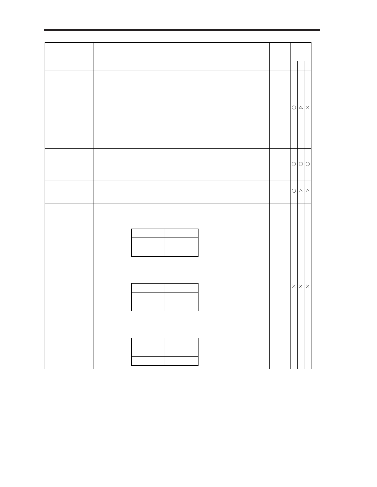
3– 12
3.WIRING
Signal
Symbol
Control
Mode
(Note 2)
PST
Functions/Applications
I/O
Division
(Note 1)
Proportion control PC CN1B
8
Connect PC-SG to switch the speed amplifier from the
proportional integral type to the proportional type.
If the servo motor at a stop is rotated even one pulse due to
any external factor, it generates torque to compensate for a
position shift. When the servo motor shaft is to be locked
mechanically after positioning completion (stop), switching
on the proportion control signal (PC) upon positioning
completion will suppress the unnecessary torque generated
to compensate for a position shift.
When the shaft is to be locked for a long time, switch on the
proportion control signal and torque control signal (TL) at
the same time to make the torque less than the rated by the
analog torque limit.
DI–1
Connec-
tor
Pin No.
Across LOP-SG
Open
Short
Control Mode
Position
Speed
External
emergency stop
EMG CN1B15Disconnect EMG-SG to bring the servo motor to an
emergency stop state, in which the servo is switched off and
the dynamic brake is operated.
Connect EMG-SG in the emergency stop state to reset that
state.
DI–1
Clear CR CN1A8Connect CR-SG to clear the position control counter on the
leading edge of the signal. The pulse width should be 10ms
or more.
DI–1
Control change LOP CN1B7 <Position/speed control change mode>
Used to select the control mode in the position/speed control
change mode.
DI–1
<Speed/torque control change mode>
Used to select the control mode in the speed/torque control
change mode.
<Torque/position control mode>
Used to select the control mode in the torque/position control
change mode.
Across LOP-SG
Open
Short
Control Mode
Speed
Torque
Across LOP-SG
Open
Short
Control Mode
Torque
Position
Note: 1. Refer to Section 3-1-4.
2. P: Position control mode, S: Speed control mode, T: Torque control mode
Page 97
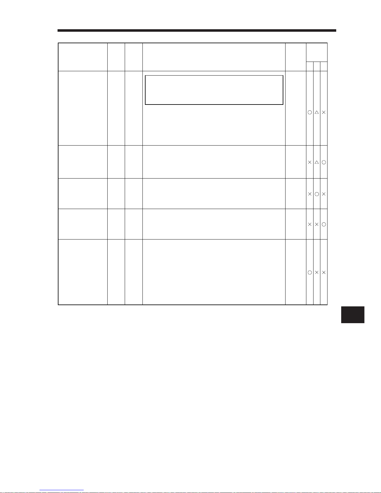
3– 13
3
3.WIRING
Signal
Symbol
Control
Mode
(Note 2)
PST
Functions/Applications
Analog torque limit
I/O
Division
(Note 1)
TLA CN1B
12
Analog
input
Connec-
tor
Pin No.
To use this signal in the speed control
mode, set any of parameters No. 43 to
48 to make TL available.
NOTICE
When the analog torque limit (TLA) is valid, torque is limited
in the full servo motor output torque range. Apply 0 to +10
VDC across TLA-LG. Connect the positive terminal of the
power supply to TLA. Maximum torque is generated at +10
V. (Refer to 1), (1) in Section 3-1-3.))
Analog torque
command
TC CN1B
12
Analog
input
Used to control torque in the full servo motor output torque
range.
Apply -8 to +8VDC across TC-LG. Maximum torque is
generated at +8V.
(Refer to 1), (1) in Section 3-1-3.)
Analog speed
command
VC CN1B2Apply -10 to +10VDC across VC-LG. Speed set in
parameter No. 25 is provided at +10V. (Refer to 1), (2) in
Section 3-1-3.)
Analog
input
Analog speed limit VLA CN1B2Apply -10 to +10VDC across VLA-LG. Speed set in
parameter No. 25 is provided at +10V. (Refer to 1), (3) in
Section 3-1-3.)
Analog
input
Forward rotation
pulse train
Reverse rotation
pulse train
PP
NP
PG
NG
CN1A
3
CN1A
2
CN1A
13
CN1A
12
Used to enter a command pulse train.
• In the open collector system (max. input frequency
200kpps):
Forward rotation pulse train across PP-SG
Reverse rotation pulse train across NP-SG
• In the differential receiver system (max. input frequency
400kpps):
Forward rotation pulse train across PG-PP
Reverse rotation pulse train across NG-NP
The command pulse train form can be changed using
parameter No. 21.
DI–2
Note: 1. Refer to Section 3-1-4.
2. P: Position control mode, S: Speed control mode, T: Torque control mode
Page 98
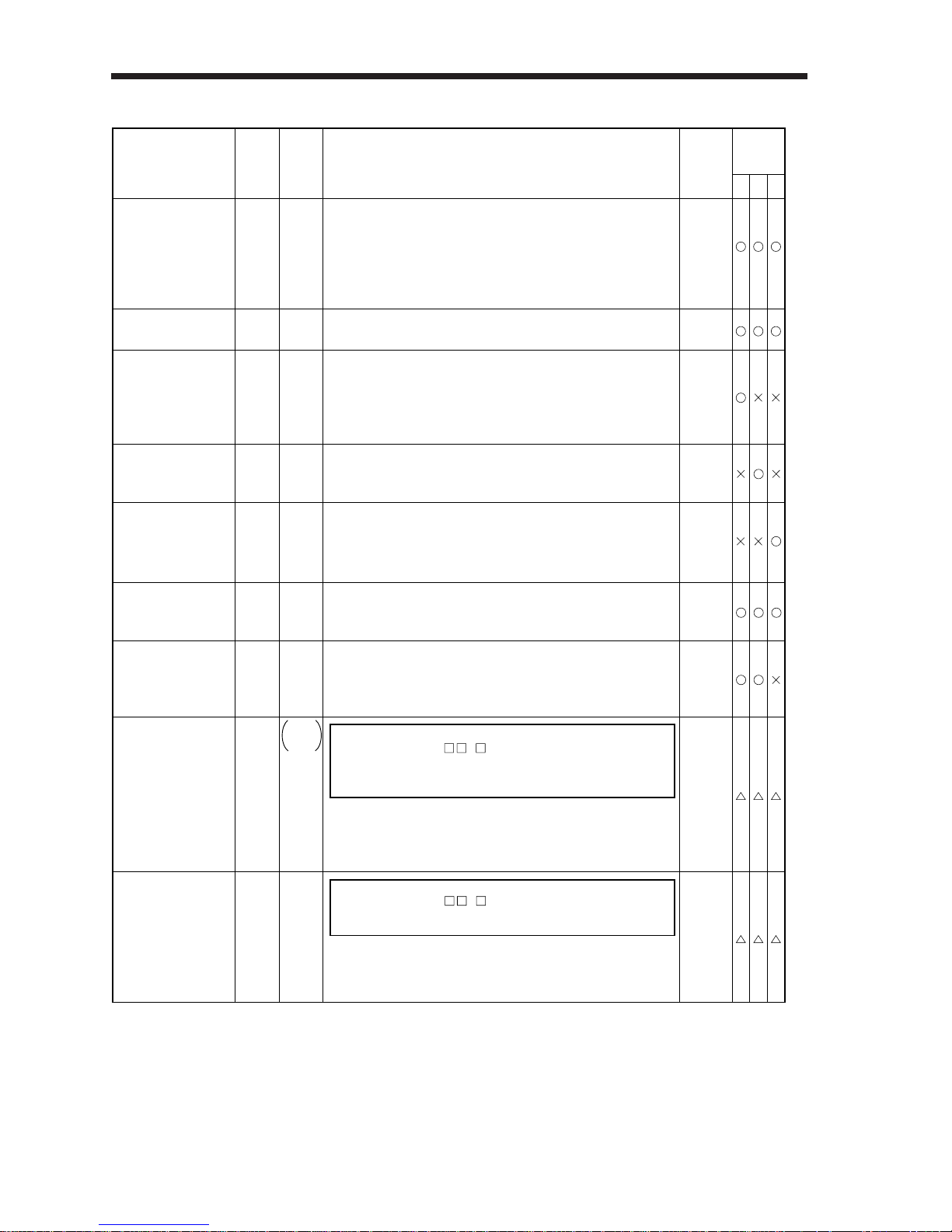
3– 14
3.WIRING
2) Output signals
Signal
Symbol
Control
Mode
(Note 2)
PST
Functions/Applications
I/O
Division
(Note 1)
Connec-
tor
Pin No.
Electromagnetic
brake interlock
MBR
CN1B
19
DO–1
Set
1 in parameter No. 1 to use this
parameter. Note that ZSP will be made
unavailable.
NOTICE
In the servo-off or alarm status, MBR-SG are disconnected.
When an alarm occurs, they are disconnected at zero speed
or less, independently of the base circuit status.
Speed reached SA CN1A18SA-SG are connected when the servo motor speed has
nearly reached the preset speed. When the preset speed is
50r/min or less, SA-SG are kept connected.
DO–1
Limiting speed VLC CN1B
6
DO–1
Zero speed ZSP CN1B19ZSP-SG are connected when the servo motor speed is zero
speed (50r/min) or less. Zero speed can be changed using
parameter No. 24.
DO–1
Limiting torque TLC CN1B6TLC-SG are connected when the torque generated reaches
the value set to the internal torque limit 1 (parameter No. 28)
or analog torque limit (TLA). They are disconnected when the
servo-on signal (SON) switches off.
DO–1
Warning WNG – DO–1
Set
1 in parameter No. 49 to use
this signal.
NOTICE
When warning has occurred, WNG-SG are connected.
When there is no warning, WNG-SG are disconnected within
1 second after power-on.
Trouble ALM CN1B18ALM-SG are disconnected when power is switched off or the
protective circuit is activated to shut off the base circuit.
Without alarm, ALM-SG are connected within 1 second after
power on. Connect the regenerative brake option or the like
with a temperature detector to make up a protective circuit.
DO–1
Ready RD CN1A19RD-SG are connected when the servo is switched on and
the servo amplifier is ready to operate.
DO–1
In position INP CN1A18INP-SG are connected when the number of droop pulses is
in the preset in-position range. The in-position range can be
changed using parameter No. 5.
When the in-position range is increased, INP-SG may be
kept connected during low-speed rotation.
DO–1
Note: 1. Refer to Section 3-1-4.
2. P: Position control mode, S: Speed control mode, T: Torque control mode
VLC-SG are connected when speed reaches the value set
to any of the internal speed limits 1 to 3 (parameters No. 8
to 10) or the analog speed limit (VLA) in the torque control
mode. They are disconnected when the servo-on signal
(SON) switches off.
Page 99
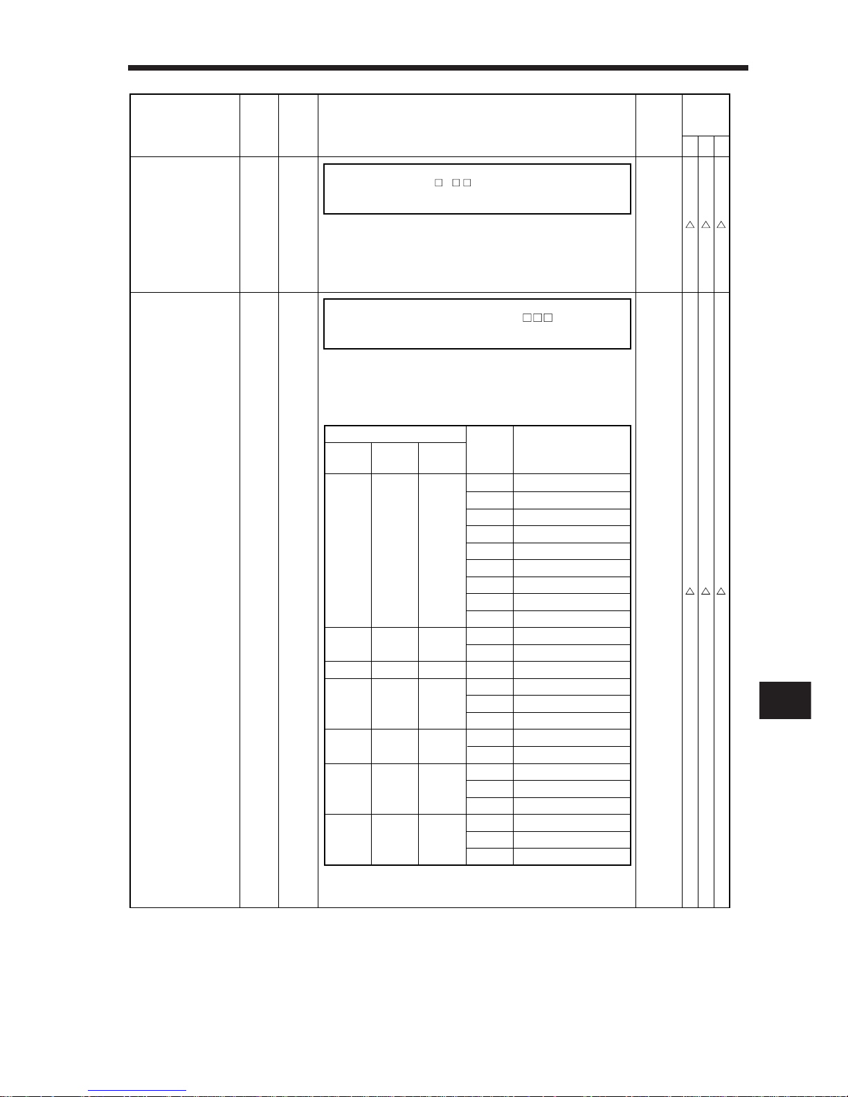
3– 15
3
3.WIRING
Signal
Symbol
Control
Mode
(Note 2)
PST
Functions/Applications
I/O
Division
(Note 1)
Connec-
tor
Pin No.
Alarm code CN1A
19
CN1A
18
CN1B
19
DO–1
To use this signal, set 1 in parameter
No. 49.
NOTICE
This signal is output when an alarm occurs. When there is
no alarm, respective ordinary signals (RD, INP, SA, ZSP)
are output.
Alarm codes and alarm names are listed below:
(Note) Alarm Code
CN1B
19 Pin
CN1A
18 Pin
CN1A
19 Pin
Alarm
Display
Name
8888
A. 11
A. 12
A. 13
A. 15
A. 17
A. 18
A. 37
A. 8E
A. 30
A. 33
A. 10
A. 46
A. 50
A. 51
A. 24
A. 32
A. 31
A. 35
A. 52
A. 16
A. 20
A. 25
Watchdog
Board error 1
Memory error 1
Clock error
Memory error 2
Board error 2
Board error 3
Parameter error
RS-232C error
Regenerative error
Overvoltage
Undervoltage
Motor overheat
Overload 1
Overload 2
Motor output ground fault
Acceleration
Overspeed
Command pulse frequency alarm
Error excessive
Encoder error 1
Encoder error 2
Absolute position erase
000
001
010
011
100
101
110
Note: 0: Each pin and SG are disconnected (OFF).
1: Each pin and SG are connected (ON)
Battery warning
BWNG
– DO–1
Set
1 in parameter No. 49 to use
this signal.
NOTICE
BWNG-SG are connected when battery cable breakage
warning (A. 92) or battery warning (A. 9F) has occurred.
When there is no battery warning, BWNG-SG are
disconnected within 1 second after power-on.
Note: 1. Refer to Section 3-1-4.
2. P: Position control mode, S: Speed control mode, T: Torque control mode
Page 100
3– 16
3.WIRING
Signal
Symbol
Control
Mode
(Note 2)
PST
Functions/Applications
I/O
Division
(Note 1)
Connec-
tor
Pin No.
Analog
Monitor
output 2
MO2
Analog
Monitor
output 1
MO1 CN34Data specified for CH1 in parameter No. 17 is output to
across MO1-LG in analog form.
Analog
output
Encoder B-phase
pulse
(Differential line
driver)
LB
LBR
CN1A
7
CN1A
17
Encoder A-phase
pulse
(Differential line
driver)
LA
LAR
CN1A
6
CN1A
16
Outputs pulses per servo motor revolution set in parameter
No. 27 in the differential line driver system. The encoder
B-phase pulse lags the encoder A-phase pulse by a phase
angle of π/2.
DO–2
Encoder Z-phase
pulse
(Open collector)
OP CN1A14Outputs the zero-point signal of the encoder. One pulse is
output per servo motor revolution. OP and LG are connected
when the zero-point position is reached. ( Negative logic)
The maximum pulse width is about 800µs. For zeroing
using this pulse, set the creep speed to 100r/min. or less.
DO–2
CN3
14
Data specified for CH2 in parameter No. 17 is output to
across MO2-LG in analog form.
Analog
output
Encoder Z-phase
pulse
(Differential line
driver)
LZ
LZR
CN1A
5
CN1A
15
The same signal as OP is output in the differential line
driver system.
DO–2
Note: 1. Refer to Section 3-1-4.
2. P: Position control mode, S: Speed control mode, T: Torque control mode
 Loading...