

Mitsubishi Electric Melservo-H, MR-H30KBN, MR-H30KAN, MR-H30KACN, MR-H30KDN Specifications
...
General-Purpose AC Servo
H Series
200VAC Large-Capacity Servo
MR-H30KAN
MR-H30KBN
MR-H30KACN
MR-H30KTN
MR-H30KDN
Specifications and Instruction Guide
Safety Instructions
(Always read these instructions before using the equipment.)
Do not attempt to install, ope rate, maint ain or inspect the servo amplif ier and servo m otor until you hav e read
through this Specifications and Instruction guide, Installation guide, Servo motor Instruction Manual and
appended docum ents c ar eful ly an d ca n us e th e eq uipm ent cor rec tl y. Do not us e t he s ervo am plif ier and ser v o
motor until you have a full knowledge of the equipment, safety information and instructions.
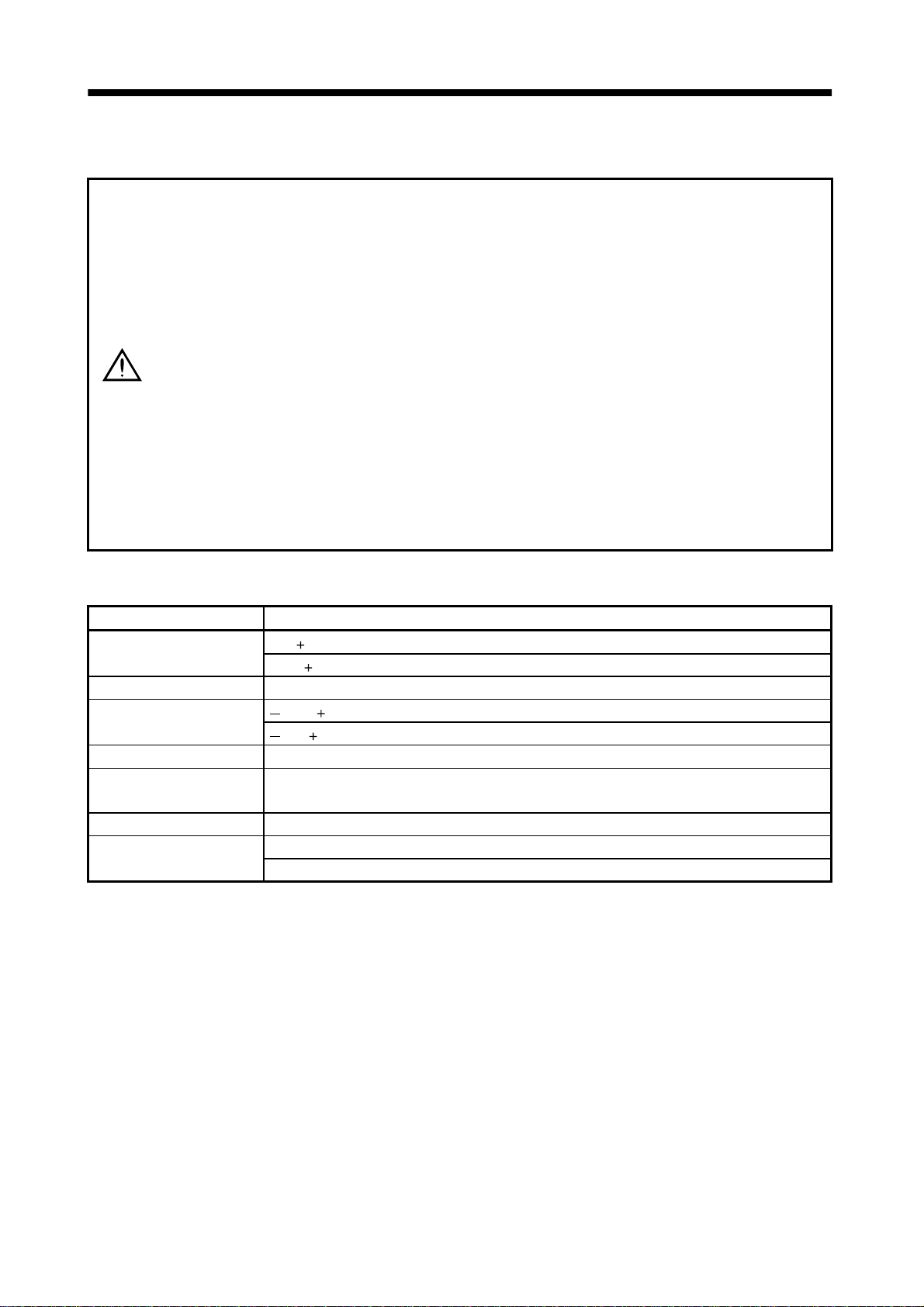
In this Instruction Manual, the safety instruction levels are classified into "WARNING" and "CAUTION".
WARNING
CAUTION
Note that the CAUTION level may lead to a serious consequence according to conditions. Please follow the
instructions of both levels because they are important to personnel safety.
What must not be done and what must be done are indicated by the following diagrammatic symbols:
: Indicates what must not be done. For example, "No Fire" is indicated by
: Indicates what must be done. For example, grounding is indicated by
In this Specific atio ns and Ins truct ion Manu al, instr uctio ns at a lo wer level than the above, ins truct ions for oth er
functions, and so on are classified into "POINT".
After reading this installation guide, always keep it accessible to the operator.
Indicates that incorrect handling may cause hazardous conditions,
resulting in death or severe injury.
Indicates that incorrect handling may cause hazardous conditions,
resulting in medium or slight injury to personnel or may cause physical
damage.
.
.
A - 1

1. To prevent electric shock, note the following:
CAUTION
• Before wiring or inspec t i on, s witc h po wer off an d wa it for more than 1 0 minutes. Then, c o nfirm the volt ag e
is safe with voltage tester. Otherwise, you may get an electric shock.
• Connect the Converter unit to ground.
• Any person who is involved in wiring and inspection should be fully competent to do the work.
• Do not atte mpt to wi re th e C onv e rte r uni t un ti l th ey have been installed. Otherwise , you may get an elect ric
shock.
• Operate the switches with dry hand to prevent an electric shock.
• The cables should not be damaged, stressed loaded,, or pinched. Otherwise, you may get an electric
shock.
• During power-on or operation, do not open the front cover. You may get an electric shock.
• Do not operate the servo amplifier with the fr ont c o ver removed. H ig h-vo l t ag e t er minals and ch ar g ing area
are exposed and you may get an electric shock.
• Except for wiring or periodic inspection, do not remove the front cover even if the power is off.
The Converter unit is charged and you may get an electric shock.
2. To prevent fire, note the following:
CAUTION
• Do not install the Converter unit and regenerative brake resistor on or near combustibles.
Otherwise a fire may cause.
• When the Converter unit has become faulty, switch off the main Converter unit power side.
Continuous flow of a large current may cause a fire.
• When a regenerative brake resistor is used, use an alarm signal to switch main power off. Otherwise, a
regenerative brake transistor fault or the like may overheat the regenerative brake resistor, causing a fire.
3. To prevent injury, note the follow
CAUTION
• Only the vo ltage specified in t he Instruction Man ual should be ap plied to each ter minal,, Otherwis e,, a
burst,, damage,, etc. may occur.
• Connect the terminals correctly to prevent a burst,, damage,, etc.
• Ensure th a t po l a rity (
• During power- on or f or some time after power-off, do no t t ouch the Conver ter unit fins , r e ge nerative brak e
resistor, servo motor, etc. Their temperatures may be high and you may get burnt.
, ) is correct. Otherwise, a burst, damage, etc. may occur.
A - 2
4. Additional instructions
The following instructions should also be fully noted. Incorrect handling may cause a fault, injury, electric
shock, etc.
(1) Transportation and installation
CAUTION
• Transport the products correctly according to their weights.
• Stacking in excess of the specified number of products is not allowed.
• Do not climb or stand on servo equipment. Do not put heavy objects on equipment.
• The Converter unit must be installed in the specified direction.
• Leave specified clearances between the Converter unit and control enclosure walls or other equipment.
• Do not install or operate the Converter unit which has been damaged or has any parts missing.
• Provide adequate pr otection to prevent screws and other co nductive matter, oil and other com bustible
matter from entering the Converter unit.
• Do not drop or strike converter unit or servo motor. Isolate from all impact loads.
• Use the servo amplifier and servo motor under the following environmental conditions:
Environment
Ambient
temperature
Ambient humidity 90%RH or less (non-condensing)
Storage
temperature
Storage humi d i t y 90%RH or less (non-condensing)
Ambience
Altitude Max. 1000m (3280 ft) above sea level
Vibration
[°C] 0 to 55 (non-freezing)
[°F] 32 to 131 (non-freezing)
[°C] 20 to 65 (non-freezing)
[°F]
[m/s2] 5.9 or less
2
[ft/s
] 19.4 or less
4 to 149 (non-freezing)
Indoors (no direct sunlight) Free from corrosive gas, flammable gas, oil mist, dust and
dirt
Conditions
Servo amplifier
• When the equipment has been stored for an extended period of time, consult Mitsubishi.
A - 3

(2) Wiring
CAUTION
• Wire the equipment correctly and securely.
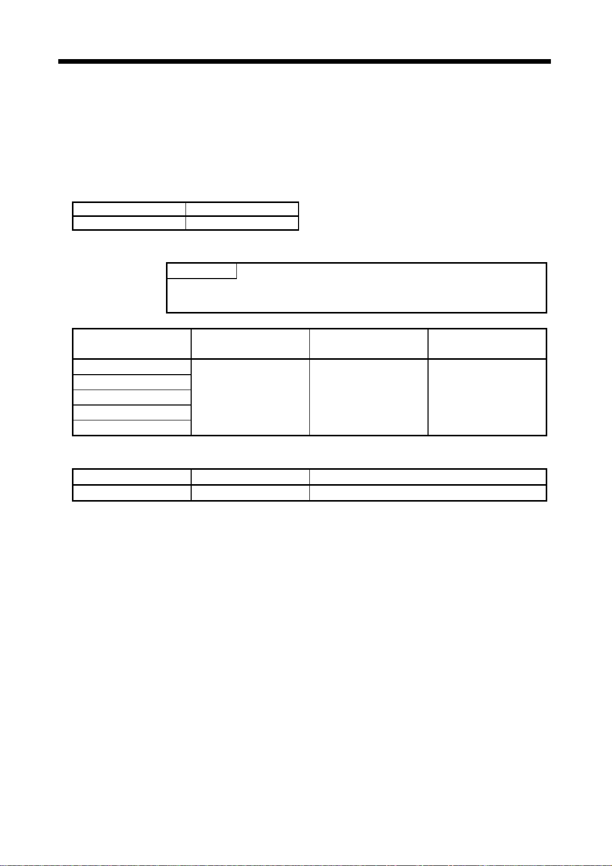
• The surge absorbing dio de i nst a l le d on the DC ou tp ut signal relay mus t b e wired in the specified direc t io n.
Otherwise, the emergency stop and other protective circuits may not operate.
Converter unit
Servo Amplifier
VIN
(24VDC)
Control
output
signal
RA
Converter unit
Servo Amplifier
VIN
(24VDC)
Control
output
signal
RA
(3) Test run adjustment
CAUTION
• Before operat ion, c heck the param eter s ettings. Im proper set tings ma y cause s ome mac hines to p erform
unexpected operation.
• The parameter settings must not be changed excessively. Operation will be insatiable.
A - 4
(4) Usage
CAUTION
• Provide an external em ergency stop circ uit to ensur e that oper ation can b e stopped and power s witched
off immediately.
• Any person who is involved in disassembly and repair should be fully competent to do the work.
• Do not modify the equipment.
• Use a noise f ilter , etc . to m in im ize t he inf luenc e of el ectromagnetic inter fere nce , whic h m a y be c ause d by
electronic equipment used near the servo amplifier.
(5) Corrective actions
CAUTION
• When any alarm has occurred, eliminate its cause, ensure safety, and deactivate the alarm before
restarting operation.
(6) Maintenance, inspection and parts replacement
CAUTION
• With age, the electrol ytic capacitor will deteriora te. To prevent a secondar y accident due to a fault, it is
recommended to replace the electrolytic capacitor every 10 years when used in general environment.
Please consult our sales representative.
(7) Disposal
CAUTION
• Dispose of the product as general industrial waste.
(8) General instruction
• To illustrate details , th e equ i pment in the d ia grams of this Specifications a nd Ins truction Manu al may have
been drawn withou t covers and safety guards. W hen the equipment is op erated, the covers and safety
guards must be installed as specified. Operation must be performed in accordance with this Specifications
and Instruction Manual.
A - 5
COMPLIANCE WITH EC DIRECTIVES
EN Standard-compliant models are scheduled for release.
CONFORMANCE WITH UL/C-UL STANDARD
UL/C-UL Standard-compliant models are scheduled for release.
<About the Manuals>
If it is the first time for you to use this servo, the optionally available Instruction Manual and Servo Motor
Instruction Manual are required in addition to this Specifications and Installation Guide. Always purchase them
and use the servo safely.
Relevant manuals
MR-H AN
Manual Name Manual No.
MR-H AN Servo Amplifier Instruction Manual SH(NA)3190
MELSERVO Servo Motor Instruction Manual
MR-H BN
SH(NA)3181
(Sub number B or later)
Manual Name Manual No.
MR-H BN Servo Amplifier Instruction Manual SH(NA)3192
MELSERVO Servo Motor Instruction Manual
SH(NA)3181
(Sub number B or later)
MR-H ACN
Manual Name Manual No.
MR-H ACN Servo Amplifier Instruction Manual SH(NA)3198
MELSERVO Servo Motor Instruction Manual
SH(NA)3181
(Sub number B or later)
MR-H TN
Manual Name Manual No.
MR-H TN Servo Amplifier Instruction Manual Scheduled for making
MELSERVO Servo Motor Instruction Manual
SH(NA)3181
(Sub number B or later)
MR-H DN
Manual Name Manual No.
MR-H-D-UE Installation Guide IB(NA)67327
MR-H AN Servo Amplifier Instruction Manual SH(NA)3190
MELSERVO Servo Motor Instruction Manual
SH(NA)3181
(Sub number B or later)
A - 6
CONTENTS
1. FUNCTIONS AND CONFIGURATION 1 - 1 to 1 - 12
1.1 Packing list..............................................................................................................................................1 - 1
1.2 Overview..................................................................................................................................................1 - 1
1.3 Function block diagram .........................................................................................................................1 - 1
1.4 Standard specification............................................................................................................................1 - 4
1.4.1 Converter unit..................................................................................................................................1 - 4
1.4.2 Servo amplifier.................................................................................................................................1 - 4
1.5 Model definition......................................................................................................................................1 - 5
1.5.1 Rating plate......................................................................................................................................1 - 5
1.5.2 Model.................................................................................................................................................1 - 5
1.6 Combination with converter unit • servo motor .................................................................................1 - 5
1.7 Parts identification.................................................................................................................................1 - 6
1.7.1 MR-HP-30KA...................................................................................................................................1 - 6
1.7.2 MR-H
1.7.3 MR-H
1.7.4 MR-H
1.7.5 MR-H
1.8 Servo system with auxiliary equipment..............................................................................................1 -11
AN•MR-H DN................................................................................................................1 - 7
BN.......................................................................................................................................1 - 8
ACN....................................................................................................................................1 - 9
TN......................................................................................................................................1 -10
2. INSTALLATION 2 - 1 to 2 - 2
2.1 Environmental conditions......................................................................................................................2 - 1
2.2 Installation direction and clearances ...................................................................................................2 - 2
3. SIGNALS AND WIRING 3 - 1 to 3 - 16
3.1 Connectors and signal layouts ..............................................................................................................3 - 2
3.1.1 MR-HP30KA ....................................................................................................................................3 - 2
3.1.2 MR-H
3.1.3 MR-H
3.1.4 MR-H
3.1.5 MR-H
3.1.6 Explanation of signals.....................................................................................................................3 - 9
3.2 Power line circuit...................................................................................................................................3 -10
3.2.1 Connection example........................................................................................................................3 -11
3.2.2 Terminal ..........................................................................................................................................3 -12
3.2.3 How to use the connection bars.....................................................................................................3 -12
3.2.4 Power-on sequence..........................................................................................................................3 -13
3.3 Servo motor side details........................................................................................................................3 -14
3.4 Grounding...............................................................................................................................................3 -15
AN•MR-H DN................................................................................................................3 - 3
BN.......................................................................................................................................3 - 4
ACN....................................................................................................................................3 - 5
TN.......................................................................................................................................3 - 7
4. DISPLAY SECTION AND OPERATION SECTION OF THE CONVERTER UNIT 4 - 1 to 4 - 8
4.1 Display flowchart....................................................................................................................................4 - 1
4.2 Status display mode...............................................................................................................................4 - 2
- 1 -

4.2.1 Display exapmles.............................................................................................................................4 - 2
4.2.2 Status display list............................................................................................................................4 - 2
4.3 Diagnostic mode......................................................................................................................................4 - 3
4.3.1 Diagnostic list...................................................................................................................................4 - 3
4.3.2 External output signal indication..................................................................................................4 - 3
4.3.3 Output signal forced output............................................................................................................4 - 4
4.4 Alarm mode.............................................................................................................................................4 - 5
4.5 Parameter mode .....................................................................................................................................4 - 6
4.5.1 Operation example...........................................................................................................................4 - 6
4.5.2 Parameter list ..................................................................................................................................4 - 7
5. INSPECTION 5 - 1 to 5- 2
5.1 Inspection ................................................................................................................................................5 - 1
5.2 Life ...........................................................................................................................................................5 - 1
6. TROUBLESHOOTING 6 - 1 to 6 - 4
6.1 Servo amplifier........................................................................................................................................6 - 1
6.1.1 Alarm codes ......................................................................................................................................6 - 1
6.1.2 Alarm corrective actions .................................................................................................................6 - 1
6.2 Converter unit.........................................................................................................................................6 - 2
6.2.1 Alarms and warning list .................................................................................................................6 - 2
6.2.2 Remedies for alarms........................................................................................................................6 - 2
6.2.3 Remedies for warnings....................................................................................................................6 - 4
6.2.4. Cleaning the alarm history............................................................................................................6 - 4
7. OUTLINE DIMENSIONAL DRAWINGS 7 - 1 to 7 - 6
7.1 Converter unit (MR-HP30KA) ..............................................................................................................7 - 1
7.2 Servo amplifier........................................................................................................................................7 - 2
7.3 Connector.................................................................................................................................................7 - 4
8. CHARACTERISTICS 8 - 1 to 8 - 4
8.1 Overload protection characteristics......................................................................................................8 - 1
8.2 Power supply equipment capacity and generated loss .......................................................................8 - 2
8.3 Dynamic brake characteristics..............................................................................................................8 - 3
9. OPTIONS AND AUXILIARY EQUIPMENT 9 - 1 to 9 - 16
9.1 Option ......................................................................................................................................................9 - 1
9.1.1 Regenerative brake option..............................................................................................................9 - 1
9.1.2 External dynamic brake..................................................................................................................9 - 5
9.1.3 Cables and connecotors...................................................................................................................9 - 7
9.1.4 Heat sink outside mounting attachment (MR-ACN) ...................................................................9 - 9
9.1.5 MR-H-D01 option card ...................................................................................................................9 -10
- 2 -

9.2 Auxiliary equipment..............................................................................................................................9 -11
9.2.1 Recommended wires.......................................................................................................................9 -11
9.2.2 No-fuse breakers, magnetic contactors.........................................................................................9 -12
9.2.3 DC reactor........................................................................................................................................9 -12
9.2.4 Noise reduction products ...............................................................................................................9 -13
9.2.5 Leakage current breaker................................................................................................................9 -14
APPENDIX App - 1 to App - 10
APPENDIX 1. 200VAC 37kW SERVO (MR-H37K )......................................................................... App - 1
Appendix 1.1 Precautions for use.......................................................................................................App - 1
Appendix 1.2 Packing list....................................................................................................................App - 1
Appendix 1.3 Standard specifications................................................................................................App - 2
Appendix 1.4 Model code.....................................................................................................................App - 3
Appendix 1.5 Combination with converter unit................................................................................ App - 4
Appendix 1.6 Installation....................................................................................................................App - 4
Appendix 1.7 Outline dimensional drawing...................................................................................... App - 5
Appendix 1.8 Characteristics..............................................................................................................App - 7
Appendix 1.9 Option and auxiliary equipment................................................................................. App - 8
Appendix 1.10 Auxiliary equipment..................................................................................................App - 9
- 3 -

MEMO
- 4 -
1. FUNCTIONS AND CONFIGURATION
1. FUNCTIONS AND CONFIGURATION
1.1 Packing list
After unpacking , check the name plate to m ake sure th at the Conv erter unit re ceived are as ordered by
the customer.
(1) Converter unit
Model Converter unit
MR-HP30KA 1
(2) Servo amplifier
POINT
• The regenerative brake resistor is not packed with the servo amplifier.
Always purchase the regenerati ve brake option. (Refer to Section 9.1.1.)
Model Servo Amplifier Connection conductors
MR-H-30KAN
MR-H30KBN
MR-H30KACN
MR-H30KTN
MR-H30KDN
121
Specification and Installtion
Guide
(3) Servo motor
Model Servo motor [pcs.] T O USE THE AC SERVO SAFELY
HA-LF30K2 1 1
1.2 Overview
The 30kW large-capacity type is newly available a s the Mitsubishi MELSER VO-H serie s general-purpo se
AC servo. This type is applicable to the fields where the same servo functions are used but a larger
capacity is necessary.
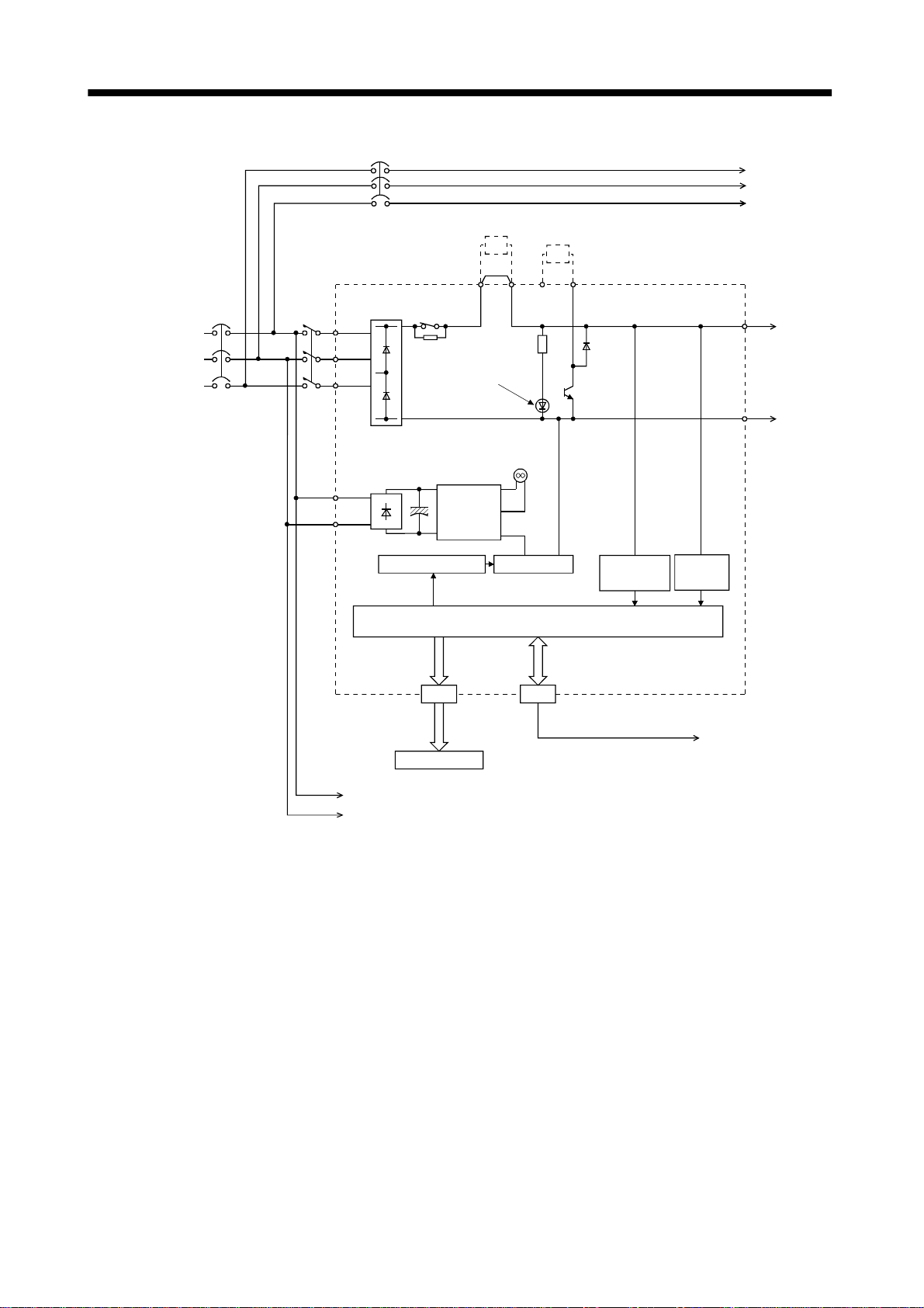
1.3 Function block diagram
The function block diagram of the Servo is shown on the next page.
1 - 1
1. FUNCTIONS AND CONFIGURATION
NFB
DCL
Regenerative brake option
BU
BV
BW
Power Suply
3-phase
200VAC
to 230VAC
NFB MC
Converter unit
DS RA
L1
L2
L3
L11
L21
Regenerative brake
P1 P2 P
CHARGE
lamp
Fan
Control
power
supply
Base amplifier
I/F
CN1 CN5
Trouble
C
Voltage
detection
CPU
Converter-servo amplifier
protection coordination
Overcurrent
protection
CN5A
P
P
N
N
L11
L12
1 - 2
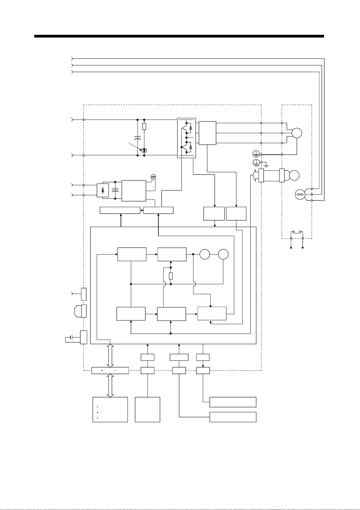
1. FUNCTIONS AND CONFIGURATION
BU
BV
BW
L11
L12
Servo amplifier(Note)
P
P
N
N
L11
L12
CHARGE
lamp
Regenerative brake
(Note)
Pulse input
Control
power
supply
Model position
control
Fan
Base amplifier
Model speed
control
Current
detector
Overcurrent
protection
Virtual
motor
Virtual
encoder
Current
detection
Servo motor
U
U
V
V
SM
W
W
CN2
Encoder
BU
BV
BW
Fan
Thermal relay
OHS1
OHS2
CN5A
MR-A-TM
termination
connector
(Option)
MR-BAT
Optional battery
(for absolute posidtion)
Note: For MR-H-AN
CN5A
CN5B
CN5
CN1 CN11 CN12
(Note)
D I/O control
Servo on
Start
Failure,etc
Model position Model speed
Actual position
control
A/D
I/F
CN1 CN4 CN3
Analog
2ch
Actual speed
control
RS-232C
Model touque
Current control
D/A
Analog monitor 2CH
Parameter uni t
1 - 3

1. FUNCTIONS AND CONFIGURATION
1.4 Standard specificati on
1.4.1 Converter unit
Model
Item
Voltage/frequency 3-phase 200 to 230VAC, 50/60Hz
Main circuit
power supply
Control power
supply
Rated output 30kw
Regenerative power
(Using regenerative brake option)
Protective function
Structure Open(IP00)
Environment
Weight [Kg] [lb] 22 [48.502]
Permissible voltage
fluctuation
Permissible frequency
fluctuation
Voltage/frequency 1-phase 200 to 230VAC, 50/60Hz
Permissible voltage
fluctuation
Permissible frequency
fluctuation
Power consumption 50W
Ambient tempera ture
Ambient humidity 90%RH or less (non-condensing)
Storage temperture
Storage humi d i t y 90%RH or les s (non-condens i ng )
Ambient
Altitud Max. 1000m (3280 ft) above sea level
Vibration
3-phase 170 to 253VAC, 50/60Hz
Within
1-phase 170to 235VAC, 50/60Hz
Within
One MR-RB139: 1300W
Three MR-RB139s: 3900W
Regenerative overvoltage shutoff, overload shutoff (electronic thermal protector)
Regenerative alarm protection, undervoltage, instantaneous power failure protection
0 to 55 [°C] (non-freezing)
32 to
Indoors (no direct sunligh t )
Free from corrosive gas, flammable gas, oil mist, dust and dirt
5.9 [m/s2] or less
19.4 [ft/s
5%
5%
131 [°F] (non-freezing)
20 to 65 [°C] (non-freezing)
4 to 149 [°F] (non-freezing)
2
MP-HP30K
] or less
1.4.2 Servo amplifier
Servo amplifier
Item
Voltage/frequency Single-phase 200 to 230VAC, 50/60Hz
Permissible voltage
Control power
supply
Main circuit power supply The main circuit power of the servo amplifier is supplied by the converter unit.
System Sine-wave PWM control, current control system
Structure Open (IP00)
Environment
Weight Kg [lb] 47 [103.617]
Function Refer to the corresponding Servo Amplifier Instruction Manual of 22kW or less.
fluctuaion
Permissible frequency
fluctuation
Power consumption 50W
Ambient tempera ture 0 to 55 [°C] (non-freezing), storage: 20 to 65 [°C] (no n -free zin g )
Humidity 90%RH or less (non-condensing), storage: 90%RH or less (non-condensing)
Ambience
Altitude Max. 1000m (3280ft) above sea level
Vibration 5.9 [m/s
Single-phase 170 to 253VAC, 50/60Hz
Within
Indoors (no direct sunligh t )
Free from corrosive gas, flammable gas, oil mist, dust and dirt
5%
2
] or less
MR-H30K
1 - 4
1. FUNCTIONS AND CONFIGURATION
1.5 Model definition
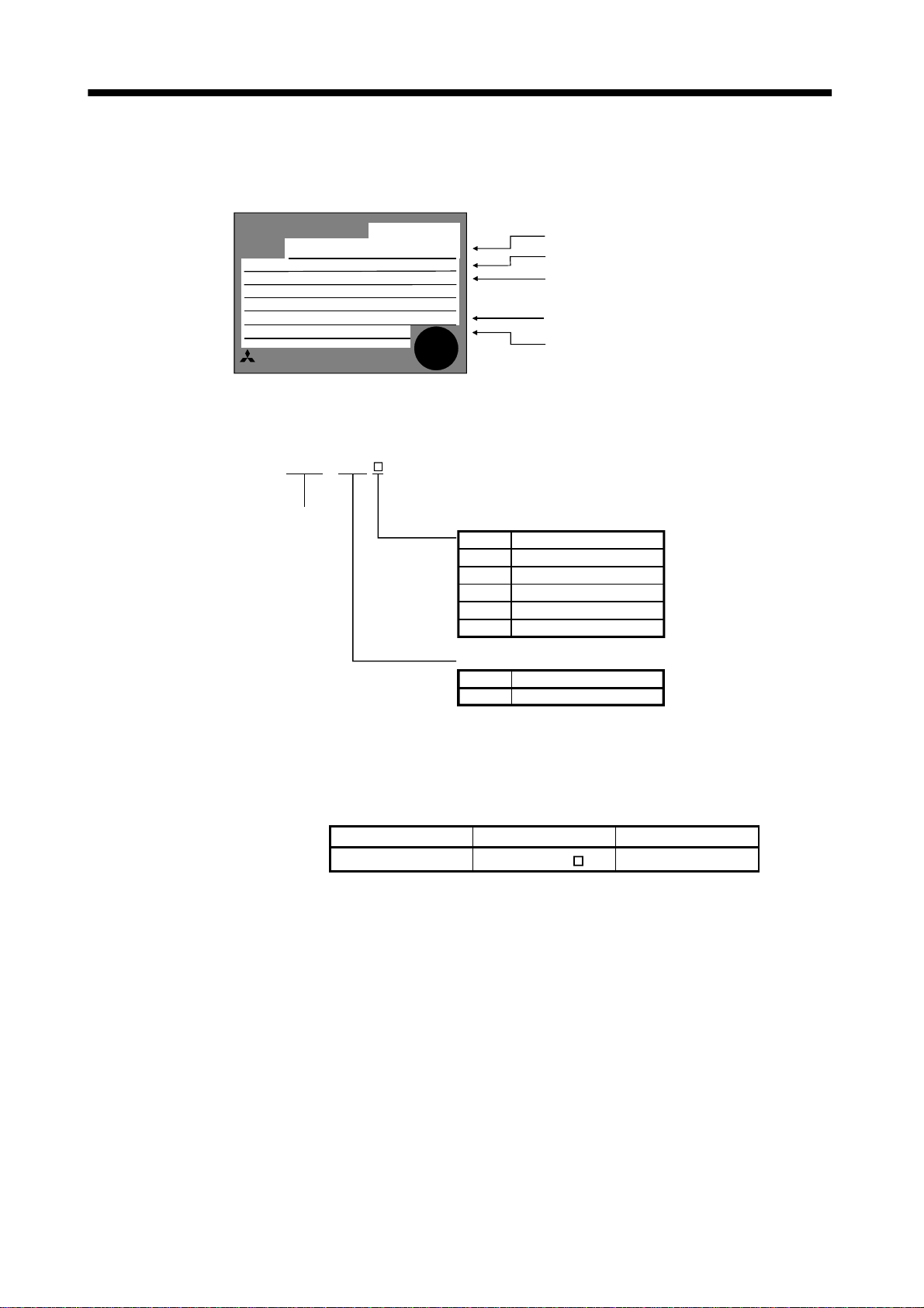
1.5.1 Rating plate
1.5.2 Model
MITSUBISHI
MODEL
POWER
MR-H30KA
POWER :
INPUT :
OUTPUT :
SERIAL :
MITSUBISHI ELECTRIC CORPORATION
MADE IN JAPAN
30kW
AC200V-230V 50/60Hz
A
TC300A156G54
MR-H
30
Series name
AC SERVO
AC SERVO
PASSED
Symbol
AN
General-Purpose Interface
BN
Positioning function built-in
ACN
TN
DN
Rated output
Symbol
30K
Model
Capacity
Applicable power supply
Rated output current
Serial number
Servo Type
SCCNET-compatible
CC-Link-compatible
Source I/O
Output [kW]
30
1.6 Combination with converter unit • servo motor
The following table table lists combinations of Convert er unit • servo amplifi ers and s ervo motors.
Converter unit Servo amplifier Servo motor
MR-HP30KA MR-H30K HA-LF30K2
1 - 5
1. FUNCTIONS AND CONFIGURATION
1.7 Parts identification
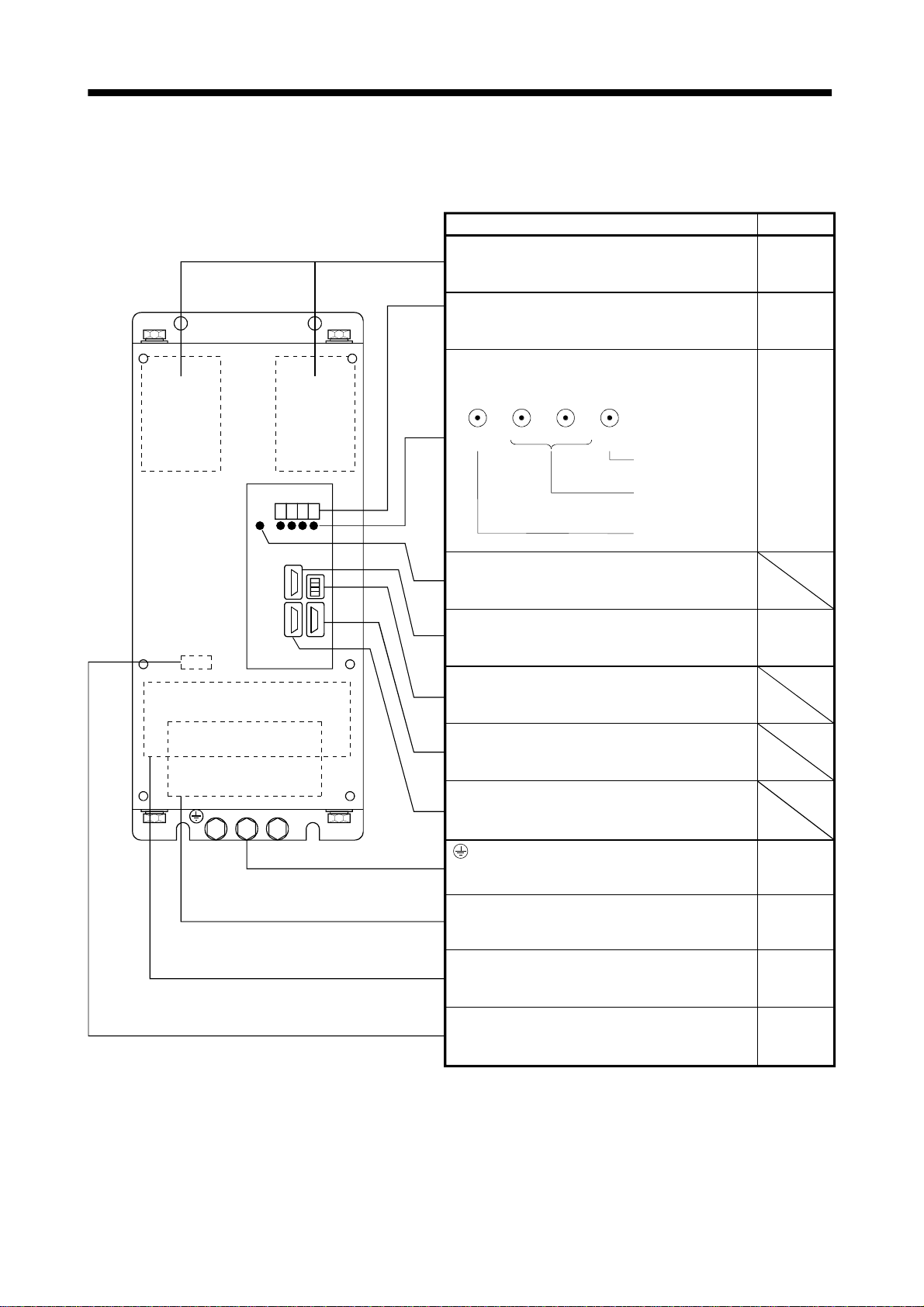
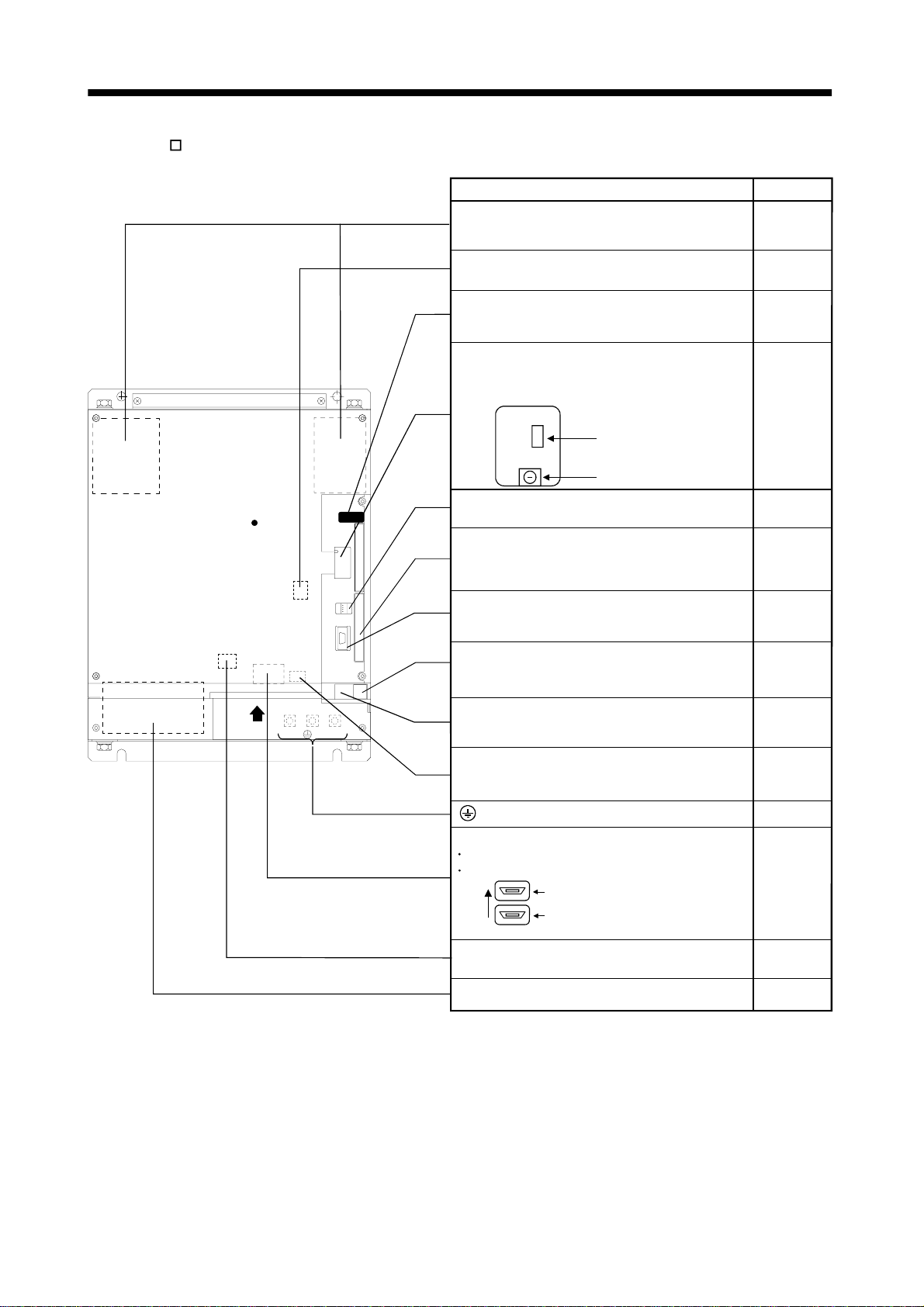
1.7.1 MR-HP-30KA
TE2-1 TE2-2
TE3
TE1-1
Name/Application
TE2-1, TE2-2 (PN terminals)
Connect to the servo amplifier using the connection
conductors supplied to the servo amplifier.
Display
The four-digit, seven-segment LED shows the servo
status and alarm number.
Operation section
Used to perform status display, diagnostic, alarm and
parameter point table operations.
MOVE UP
Charge lamp
Lit to indicate that the main circuit is charged. While
this lamp is lit, do not reconnect the cables.
CN1
Outputs an alarm signal.
CN3
For maker adjustment. Leave this open.
DOWN
SET
Used to set data.
Used to change the
display data in each
mode.
Used to change the
mode.
Refer To
Section
3.2.2(1)
Chapter 4
Chapter 4
Section 3.1.2
TE1-2
CN6
For maker adjustment. Leave this open.
CN5
Connect to CN5A of the servo amplifier.
(Ground terminal)
TE1-2
Supply main circuit power.
TE1-1
Connect the regenerative brake option or DC reactor.
TE3
Supply control circuit power.
Section 3.2.2
Section 3.2.2
Section 3.2.2
Section 3.2.2
1 - 6
1. FUNCTIONS AND CONFIGURATION
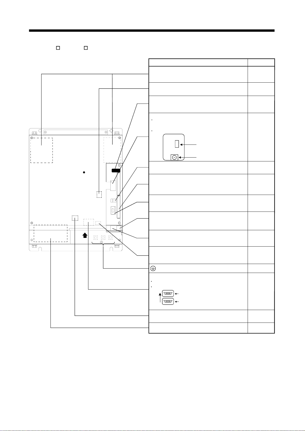
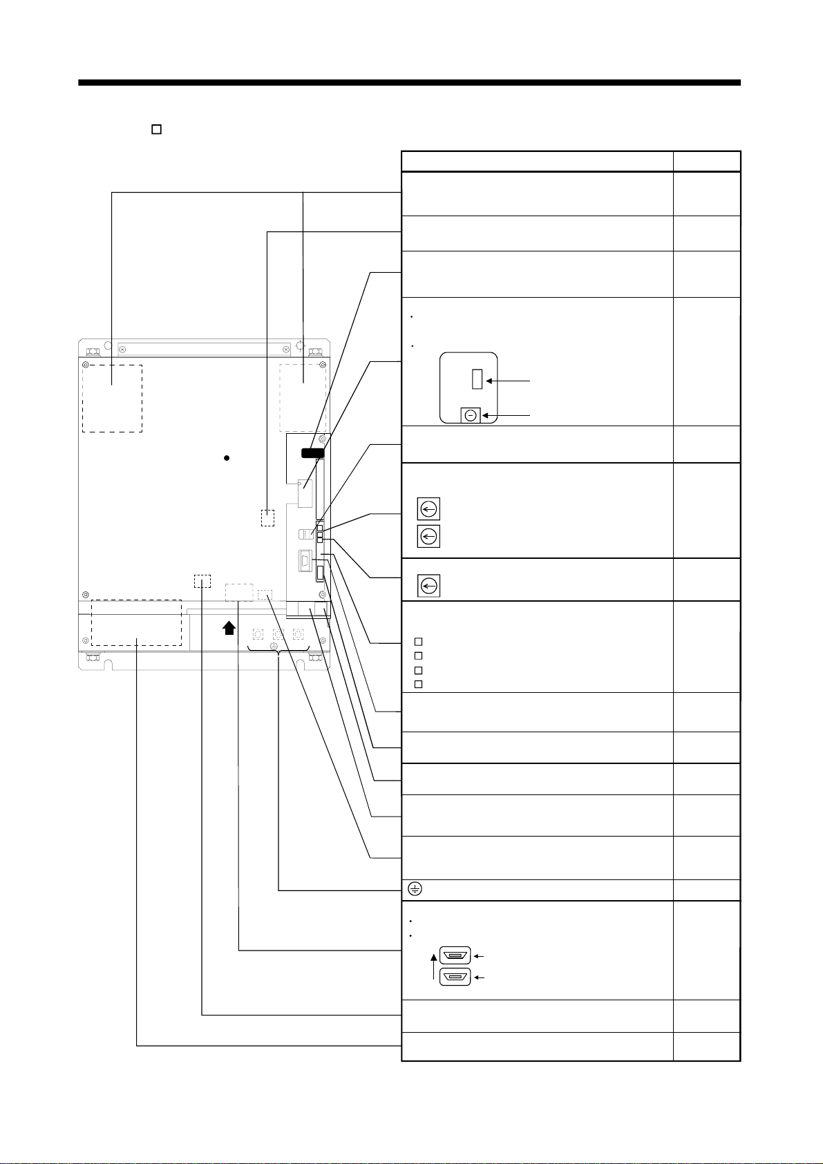
1.7.2 MR-H AN•MR-H DN
TE2-1
TE1
Charge lamp
a
TE2-2
CN3
CN4
CN1
Name/Application
TE2-1, TE2-2 (PN terminals)
Connect to the PN terminals of the converter unit
using the connection conductors supplied.
Battery holder
Contains the battery for absolute position data backup.
Display
The four-digit, seven-segment LED shows the servo
status and alarm number.
Switch window
CN5 : Connector for connection of the battery for
absolute position detection
CS1 : Status indication select switch
CN5
CS1
CN3 (Analog monitor output connector)
Used to output an analog monitor signal.
CN12 (MR-H-D01 option card)
Used to input an auxiliary pulse train when the
MR-H-D01 option card is loaded.
CN4 (Communication connector)
Used for connection with the MR-PRU01A/personal
computer.
CN11 (MR-H-D01 option card)
Used to connect extra digital I/O signals when the
MR-H-D01 option card is loaded.
CN1 (I/O signal connector)
Used to connect digital I/O signals.
CN2 (Encoder connector)
Connector for connection of the servo motor encoder.
(Ground terminal)
CN5A, CN5B (Converter unit connectors)
CN5A: Connect to CN5 of the converter unit.
CN5B: Connect the termination connector (MR-A-TM).
CN5A
Front
CN5B
View a
TE3 (Control circuit terminal)
Supply control circuit power.
TE1
Connect to U, V, W of the servo motor.
Refer To
Section 3.2.2
Servo Amplifier
Instruction
Manual
Servo Amplifier
Instruction
Manual
Servo Amplifier
Instruction
Manual
Servo Amplifier
Instruction
Manual
Section 3.1.2
Section 9.1.5
Servo Amplifier
Instruction
Manual
Servo Amplifier
Instruction
Manual
Section 3.1.2
Section 9.1.5
Servo Amplifier
Instruction
Manual
Section 3.1.2
Servo Amplifier
Instruction
Manual
Section 3.1.2
Servo Amplifier
Instruction
Manual
Section 3.2.2
Section 3.2.1
Section 3.2.2
Section 3.2.2
1 - 7
1. FUNCTIONS AND CONFIGURATION
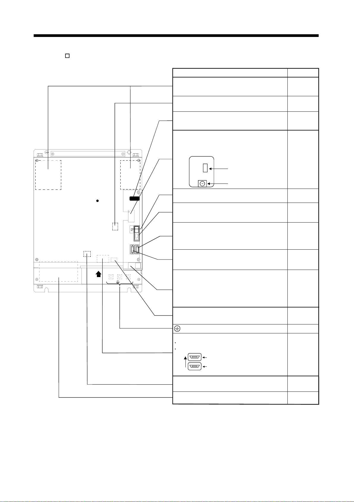
1.7.3 MR-H BN
TE2-1
TE1
Charge lamp
a
TE2-2
CN3
CN6
CN4
CN1BCN1A
Name/Application
TE2-1, TE2-2 (PN terminals)
Connect to the PN terminals of the converter unit
using the connection conductors supplied.
Battery holder
Contains the battery for absolute position data backup.
Display
The four-digit, seven-segment LED shows the servo
status and alarm number.
Switch window
· CN5: Connector for connection of the battery for
absolute position detection
· CN1: Axis select switch
CN5
CS1
CN3 (Analog monitor output connector)
Used to output an analog monitor signal.
CN4 (Communication connector)
Used for connection with the MR-PRU01A/personal
computer.
CN1B (Bus cable connector)
Used to connect a bus cable which links with a
subsequent axis servo amplifier or termination
controller.
CN1A (Bus cable connector)
Used to connect a bus cable which links with a
controller or preceding-axis servo amplifier.
CN6 (I/O signal connector)
Connect the CN6 connector which comes standard.
The CN6 connector is shorted between EM1-EM2.
When making up an emergency stop circuit externally,
open EM1-EM2 and connect an external emergency
stop switch across them.
CN2 (Encoder connector)
Connector for connection of the servo motor encoder.
(Ground terminal)
CN5A, CN5B (Converter unit connectors)
CN5A: Connect to CN5 of the converter unit.
CN5B: Connect the termination connector (MR-A-TM).
CN5A
Front
CN5B
View a
TE3 (Control circuit terminal)
Supply control circuit power.
TE1
Connect to U, V, W of the servo motor.
Refer To
Section 3.2.2
Servo Amplifier
Instruction
Manual
Servo Amplifier
Instruction
Manual
Servo Amplifier
Instruction
Manual
Servo Amplifier
Instruction
Manual
Servo Amplifier
Instruction
Manual
Servo Amplifier
Instruction
Manual
Servo Amplifier
Instruction
Manual
Section 3.1.3
Servo Amplifier
Instruction
Manual
Section 3.1.3
Servo Amplifier
Instruction
Manual
Section 3.2.2
Section 3.2.1
Section 3.2.2
Section 3.2.2
1 - 8
1. FUNCTIONS AND CONFIGURATION
1.7.4 MR-H ACN
TE2-1
TE1
Charge lamp
a
TE2-2
CN3
CN4
CN1
Name/Application
TE2-1, TE2-2 (PN terminals)
Connect to the PN terminals of the converter unit
using the connection conductors supplied.
Battery holder
Contains the battery for absolute position data backup.
Display
The four-digit, seven-segment LED shows the servo
status and alarm number.
Switch window
CN5 : Connector for connection of the battery for
x
absolute position detection
CS1 : Status indication select switch
x
CN5
CS1
CN3 (Analog monitor output connector)
Used to output an analog monitor signal.
CN12 (MR-H-D01 option card)
Used to input an auxiliary pulse train when the
MR-H-D01 option card is loaded.
CN4 (Communication connector)
Used for connection with the MR-PRU01A/personal
computer.
CN11 (MR-H-D01 option card)
Used to connect extra digital I/O signals when the
MR-H-D01 option card is loaded.
CN1 (I/O signal connector)
Used to connect digital I/O signals.
CN2 (Encoder connector)
Connector for connection of the servo motor encoder.
(Ground terminal)
CN5A, CN5B (Converter unit connectors)
CN5A: Connect to CN5 of the converter unit.
CN5B: Connect the termination connector (MR-A-TM).
CN5A
Front
CN5B
View a
TE3 (Control circuit terminal)
Supply control circuit power.
TE1
Connect to U, V, W of the servo motor.
Refer To
Section 3.2.2
Servo Amplifier
Instruction
Manual
Servo Amplifier
Instruction
Manual
Servo Amplifier
Instruction
Manual
Servo Amplifier
Instruction
Manual
Section 9.1.5
Servo Amplifier
Instruction
Manual
Servo Amplifier
Instruction
Manual
Section 9.1.5
Servo Amplifier
Instruction
Manual
Section 3.1.4
Servo Amplifier
Instruction
Manual
Section 3.1.4
Servo Amplifier
Instruction
Manual
Section 3.2.2
Section 3.2.1
Section 3.2.2
Section 3.2.2
1 - 9
1. FUNCTIONS AND CONFIGURATION
1.7.5 MR-H TN
TE2-1
TE1
Charge lamp
a
TE2-2
CN3
CN4
CN1
Name/Application
TE2-1, TE2-2 (PN terminals)
Connect to the PN terminals of the converter unit
using the connection conductors supplied.
Battery holder
Contains the battery for absolute position data backup.
Display
The four-digit, seven-segment LED shows the servo
status and alarm number.
Switch window
CN5 : Connector for connection of the battery for
absolute position detection
CS1 : Status indication select switch
CN5
CS1
CN3 (Analog monitor output connector)
Used to output an analog monitor signal.
Station number switches
Used to set the station number of the servo amplifier.
SW4: Used to set the second digit. (X10)
SW3: Used to set the first digit. (X1)
SW2 (Baudrate switch)
Used to choose the CC-Link communication
baudrate.
Communication alarm display
Shows the alarm in CC-Link communication.
RD
SD
L.ERR
L.RUN
CN4 (Communication connector)
Used for connection with the MR-PRU01A/personal
computer.
SW1 (Occupied station count switch)
Use to set the number of stations occupied.
CC-Link terminal block
Used to wire the CC-Link cables.
CN1 (I/O signal connector)
Used to connect digital I/O signals.
CN2 (Encoder connector)
Connector for connection of the servo motor encoder.
(Ground terminal)
CN5A, CN5B (Converter unit connectors)
CN5A: Connect to CN5 of the converter unit.
CN5B: Connect the termination connector (MR-A-TM).
CN5A
Front
CN5B
View a
TE3 (Control circuit terminal)
Supply control circuit power.
TE1
Connect to U, V, W of the servo motor.
Refer To
Section 3.2.2
Servo Amplifier
Instruction
Manual
Servo Amplifier
Instruction
Manual
Servo Amplifier
Instruction
Manual
Servo Amplifier
Instruction
Manual
Servo Amplifier
Instruction
Manual
Servo Amplifier
Instruction
Manual
Servo Amplifier
Instruction
Manual
Servo Amplifier
Instruction
Manual
Servo Amplifier
Instruction
Manual
Servo Amplifier
Instruction
Manual
Section 3.1.5
Servo Amplifier
Instruction
Manual
Section 3.1.5
Servo Amplifier
Instruction
Manual
Section 3.2.2
Section 3.2.1
Section 3.2.2
Section 3.2.2
1 - 10
1. FUNCTIONS AND CONFIGURATION
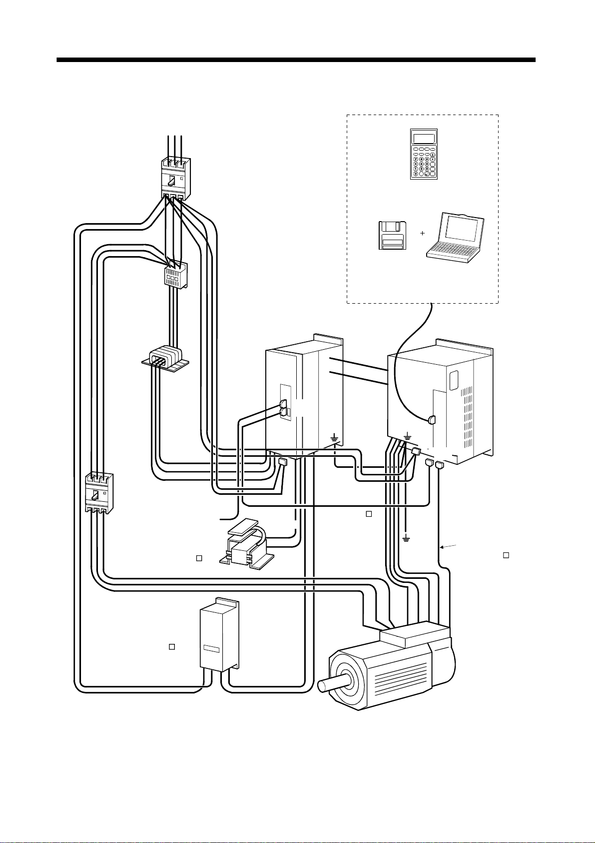
1.8 Servo system with auxiliar y equipm ent
No-fuse
breaker
Magnetic
contactor
Line noise
filter
3-phas e, 200 to 230VAC
RS T
(NFB)
(MC)
(FR-BLF)
(Note3)
Converter unit
CN1
CN5
Servo Configuration
software
The parameter unit or Servo
Configuration software is required
for parameter setting .
Parameter unit cable
communication cable
P
N
or
(Note 1)
P
N
Parameter unit
or
Servo amplifier
CN4
Personal
computer
No-fuse
breaker
(NFB)
(Control signal)
Power factor improving
DC reactor
(MR-DCL K)
Regenerative
brake option
(MR-RB )
(Note 2)
R1
U
V
W
L11
L21
CN5A
L1
L2
L3
L11
L21
P1
PC
(MR-J2HBUS M)
P2
CN2
CN1
Encoder cable
(MR-HSCBL M)
U
BU
BV
BW
VWE
P
S1
C
Servo motor
HA-LF series
1 - 11

1. FUNCTIONS AND CONFIGURATION
MEMO
1 - 12
2. INSTALLATION
2. INSTALLATION
• Stacking in excess of the limited number of products is not allowed.
• Install the equipment to incombustibles. Installing them directly or close to
• Install the equipment in a load-bearing place in accordance with this Instruction
• Do not get on or put heavy load on the equipment to prevent injury.
• Use the equipment within the specified environmental condition range.
• Provide an adequ a te prot e cti on to preve nt scr ew s, meta lli c de t rit u s and ot he r
CAUTION
• Do not block the intake/exhaust ports of the Converter unit and servo amplifier.
• Do not subject the Converter unit and servo amplifier to drop impact or shock loads
• Do not install or operate a faulty Converter unit and servo amplifier.
• When the product has been stored for an extended period of time, consult
combustibles will led to a fire.
Manual.
conductive matter or oil and other combustible matter from entering the Converter
unit and servo amplifier.
Otherwise, a fault may occur.
as they are precision equipment.
Mitsubishi.
2.1 Environmental con dit ions
Environment Conditions
Ambient temperature
Ambient humidity 90%RH or less (non-condensing)
Storage temperature
Storage humidity 90%RH or less (non-condensing)
Ambient
Altitude Max. 1000m (3280 ft) above sea level
Vibration
0 to 55 [°C] (non-freezing)
32 to
131 [°F] (non-freezing)
20 to 65 [°C] (non-freezing)
4 to 149 [°F] (non-freezing)
Indoors (no direct sunlight)
Free from corrosive gas, flammable gas, oil mist, dust and dirt
5.9 [m/s2] or less
2
19.4 [ft/s
] or less
2 - 1
2. INSTALLATION
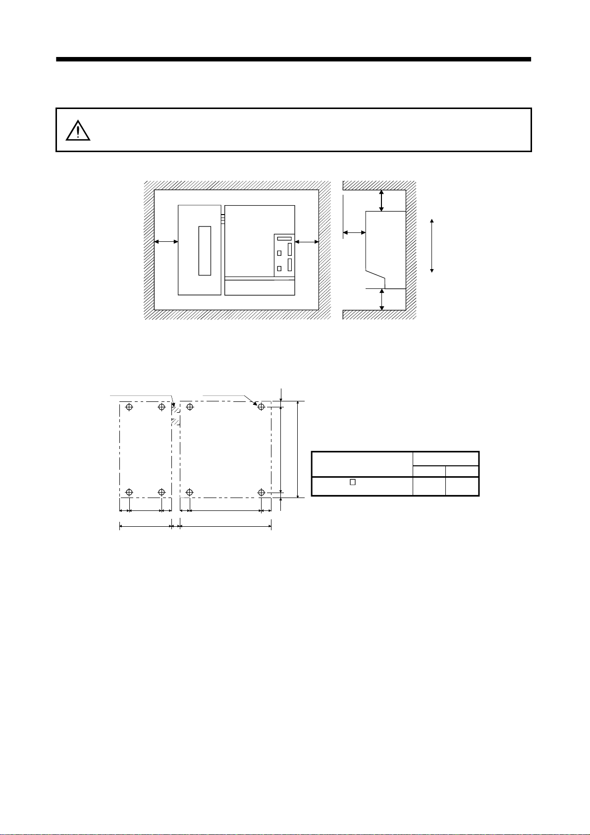
2.2 Installation direction and clearances
• Install the equipment in the specified direction. Not doing so can cause a failure.
CAUTION
(1) Installation of one servo amplifier
• Leave the specified clearances between the converter unit/servo amplifier and the
control box inside walls or other equipment. Not doing so can cause a failure.
Converter unit
50mm
(1.969in)
or more
Servo Amplifier
50mm
(1.969in)
or more
100mm
100mm
(3.937in)
or more
(3.937in)
or more
Top
Bottom
120mm
(4.724in)
or more
Front view
Side view
(2) Mounting dimensional diagram
Exclusive
connection co nductor
Converter
unit
110
(4.33)
200
(4.66)
45
(1.77)
(0.47)
45
(1.77)
(1.77)
20
8-M10 screw
Servo amplifier
45
W2
W1
45
(1.77)
10(0.39)10
480(18.9)
(0.39)
500(19.69)
Servo Amplifier Model
MR-H30K
[Unit: mm]
([Unit: in])
Dimension
W1
450
(17.717)
W2
360
(14.173)
(3) Others
When using heat generating equipment such as the regenerative brake option, install them with full
consideration of heat generation so that the Converter unit and servo amplifier is not affected.
Install the Converter unit and servo amplifier on a perpendicular wall in the correct vertical direction.
2 - 2
3. SIGNALS AND WIRING
3. SIGNALS AND WIRING
• Any person who is involved in wiring should be fully competent to do the work.
• Before starting wiring, make sure that the charge lamp is off and the voltage is safe
in the tester or the like more than 10 minutes after power-off. Otherwise, you may
get an electric shock.
WARNING
CAUTION
• Ground the Conv e rte r uni t an d se rvo a mpl i fie r and th e se rvo mot o r se cur ely .
• Do not attempt to wire the Converter unit and servo amplifier and servo motor until
they have been installed. Otherwise, you may get an electric shock.
• The cables should not be damaged, stressed excessively, loaded heavily, or
pinched. Otherwise, you may get an electric shock.
• Wire the equipment correctly and securely. Otherwise, the servo motor may
misoperate resulting in injury.
• Connect cables to correct terminals to prevent a burst, fault, etc.
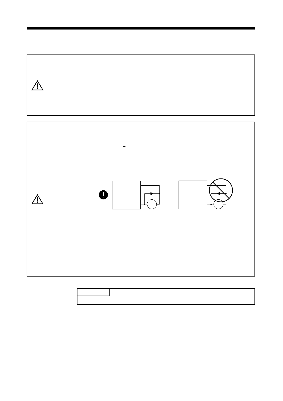
• Ensure th a t po l a rity (
• The surge absorbing diode installed to the DC relay designed for control output
should be fitted in the specified direction. Otherwise, the signal is not output due to
a fault, disabling the emergency stop and other protective circuits.
, ) is correct. Otherwise, a burst, damage, etc. may occur.
Converter unit
Servo Amplifier
VIN
(24VDC)
Control
output
signal
RA
Converter unit
Servo Amplifier
VIN
(24VDC)
Control
output
signal
RA
• Use a noise filter, etc. to minimize the influence of electromagnetic interference,
which may be given to electronic equipment used near the Converter unit and
servo amplifier.
• Do not install a power capacitor, surge suppressor or radio noise filter (FR-BIF
option) with the power line of the servo motor.
• When using the regenerative brake resistor, switch power off with the alarm signal.
Otherwise, a transistor fault or the like may overheat the regenerative brake
resistor, causing a fire.
• Do not modify the equipment.
POINT
• The pin with the same signal name are connected in the servo amplif ier.
3 - 1
3. SIGNALS AND WIRING
3.1 Connectors and signal layouts POINT
• The signal layouts of the connectors are views from the wiring section of
the cable connectors.
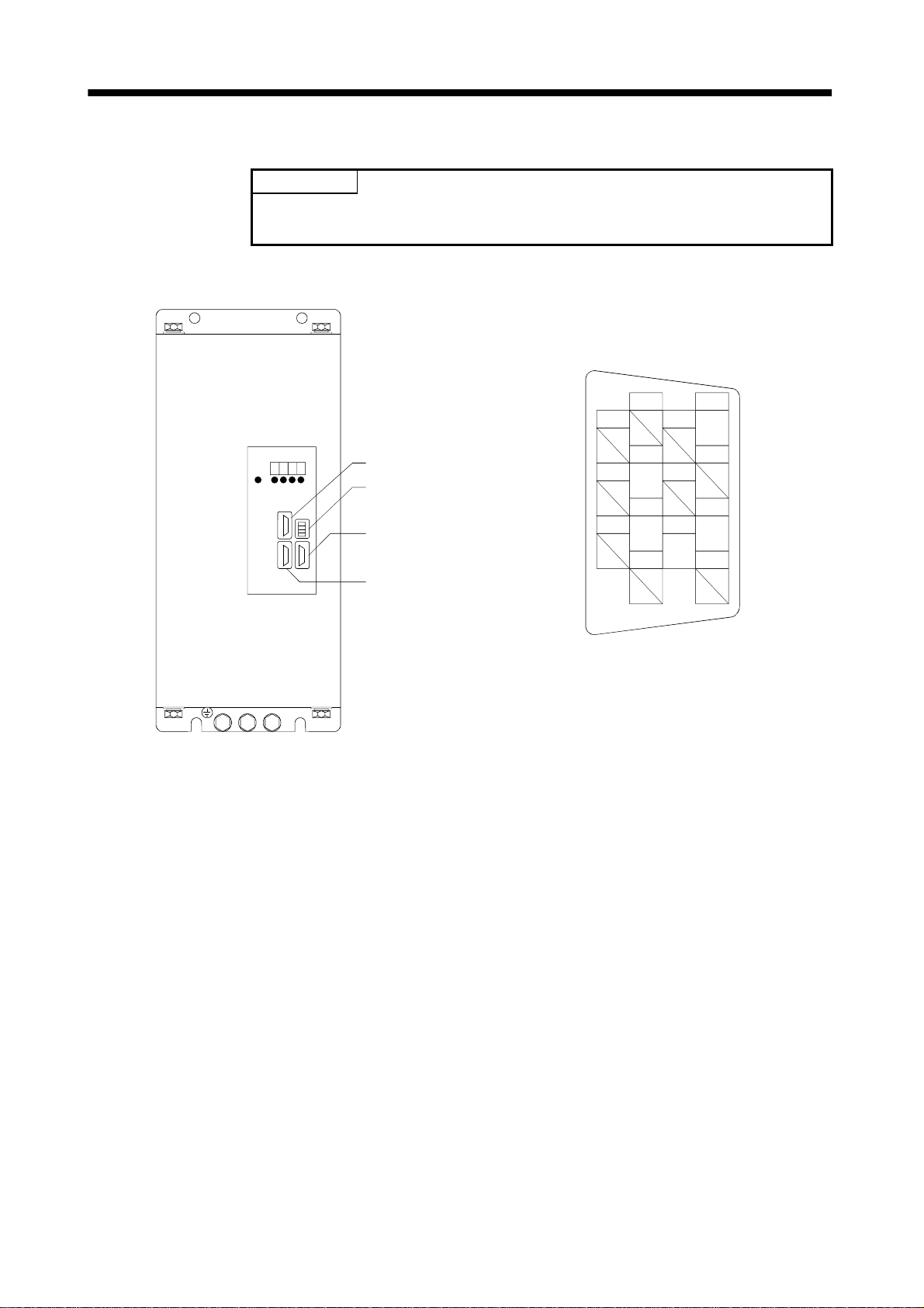
3.1.1 MR-HP30KA
CN1 (alarm output connector)
Model: 10114-3000VE(3M make)
Converter unit
CN1
CN3
Leave this open.
CN6
Leave this open.
CN5
Connect to CN5A of the servo
amplifier.
1
2
3
4
SE
5
6
SG
7
9
11
13
COM
8
ALM
10
12
VDD
14
3 - 2
3. SIGNALS AND WIRING
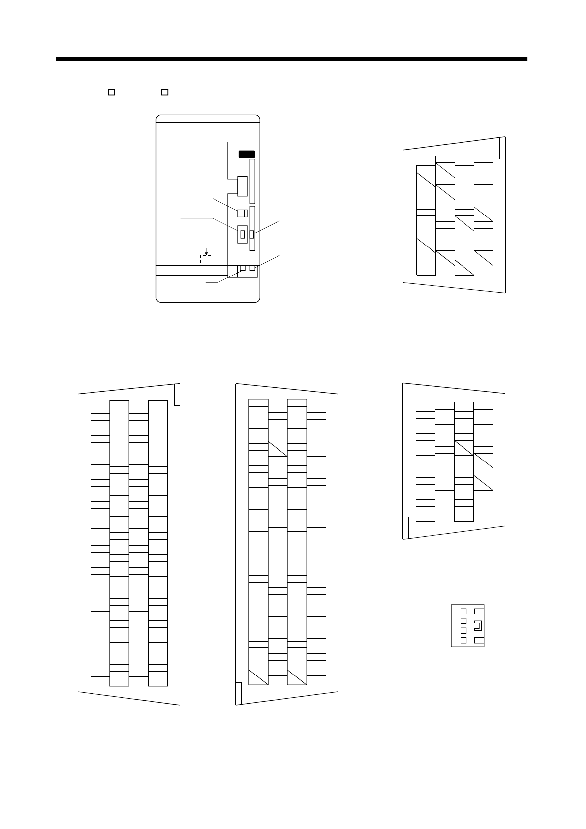
3.1.2 MR-H AN•MR-H DN
Servo amplifier
CN2 (for encoder signals)
Model PCR-S20FS (Honda Tsushin make)
CN4
(For parameter unit)
CN2
CN1
CN1 (for I/O signals)
Model PCR-S50FS (Honda Tsushin make)
27
TLAP
29
TLAN
31
FPA
33
OP
35
NP
37
CR
39
LSN
41
DI0
43
DI2
45
DI4
47
SG
49
RD
26
N15R
28
LG
30
LG
32
FPB
34
LG
36
NPR
38
LSP
40
SG
42
DI1
44
DI3
46
EMG
48
ALM
50
SD
2
VC
4
LA
6
LB
8
LZ
10
PP
12
SON
14
PC
16
SG
18
PPO
20
VIN
22
VDD
24
PF
1
P15R
3
LG
5
LAR
7
LBR
9
LZR
11
PPR
13
TL
15
RES
17
SG
19
NPO
21
VDD
23
ZSP
25
TLC
CN3
(Note)
CN12
(MR-H-D01)
(Note)
CN11
(MR-H-D01)
Note: Used when the MR-H-D01
option card is loaded.
CN11 (for MR-H-D01 I/O signals)
Model PCR-S50FS (Honda Tsushin make)
25
DO13
23
DO11
21
VDD
19
DI19
17
SG
15
DI05
13
DI03
11
DI01
9
DO05
7
DO03
5
DO01
3
DI21
1
24
DO12
22
20
VIND
18
DI18
16
SG
14
DI04
12
DI02
10
DI10
8
DO04
6
DO02
4
DO00
2
DI20
50
SD
48
DO14
46
DI17
44
DI15
42
DI13
40
SG
38
DI10
36
DI08
34
DI06
32
DO09
30
DI23
28
DI22
26
DO15
SG
DI16
DI14
DI12
DI11
DI09
DI07
DO10
DO08
DO07
DO06
12
14
BAT
16
P5
18
20
SD
11
13
15
LG
17
LG
19
MR
1
2
LG
LG
3
4
MRR
5
6
7
8
P5
P5
9
10
CN12 (for MR-H-D01 input signals)
Model PCR-S20FS (Honda Tsushin make)
10
49
47
45
43
41
39
37
35
33
31
9
OP24
OP5
8
7
P5
P5
6
5
NP1D
PP1D
4
3
NPD
NPRD
2
1
LG
NTR
CN3 (for analog monitor)
Model 171822-4 (AMP mak e)
(M01) 1
19
SG
17
15
PTR
13
PPRD
11
LG
20
SD
18
P24
16
14
12
PPD
(M02) 2
29
27
(M0G) 4
3 - 3
 Loading...