

Changes for the Better
Models
MR-FT35EH-SW-C
MR-FT46EH-SW-C
MR-FT51EH-SW-C
CONTENTS
1. SPECIFICATIONS......................................................
2. OUTLINES AND DIMENSIONS...................................
3. WIRING DIAGRAM....................................................
4. REFRIGERANT CIRCUIT...........................................
5. NAME OF THE PARTS...............................................
6. TROUBLE SHOOTING................................................
6.1 TROUBLE CRITERION OF MAIN PARTS............
6.2 TEST POINT DIAGRAM OF MAIN CONTROL
BOARD..............................
6.3 LED TROUBLE DISPLAY AND CHECK
POINT.....................................................................
6.4 IMPORTANCE DETAIL OF FAULT ANALYSIS.....
7. DISASSEMBLY INSTRUCTIONS...............................
8. PARTS LIST...............................................................
2015
SERVICE MANUAL
NO.SM-RE-1508
MITSUBISHI
ELECTRIC
HOME REFRIGERATORS
C..............Taiwan
1
3
6
8
10
12
12
14
15
17
19
22
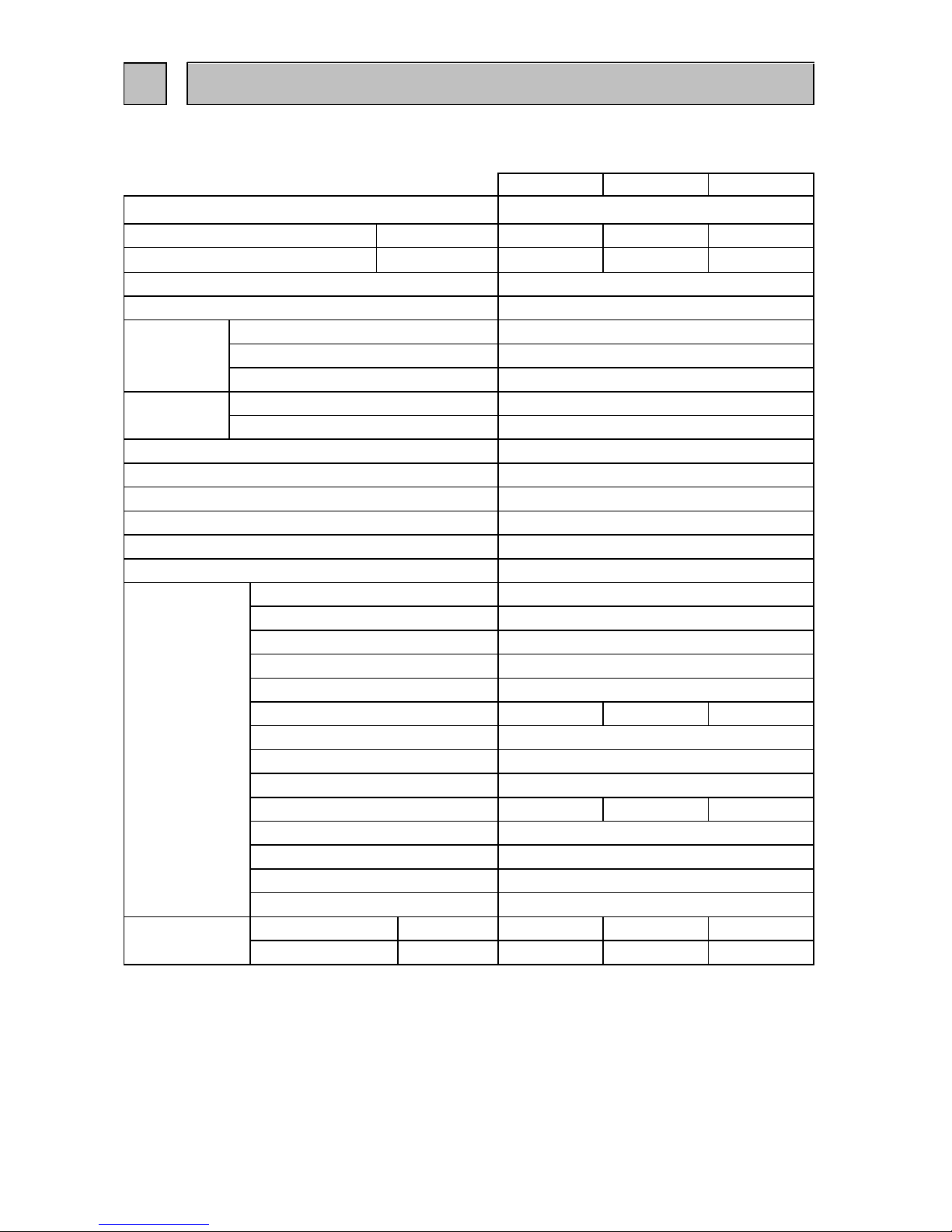
1.1 SPECIFICATIONS
MR-FT35EH-C MR-FT46EH-C MR-FT51EH-C
Egg rack
1 pc.
2 pcs.
2 pcs.
Forced air convection
Surround cooling,multi air flow,front air flow
2 pcs.
1 pc.
1 pc.
Automatic control
Shipping
Weight
kg
kg
Vegetable case
Drain pan
Unit
Adjust pocket
Bottle pocket
Acrylic resin coated steel
ABS resin
Foamed cyclopenthane
Fin and tube type
Concealed type
Crystal shelf (R)
Automatic (Heater defrost)
Freezer pocket
Slide chilled case
Crystal shelf (F)
Temperature control system
Refrigerator room light
Ice tray
Ice box
Accessories
Bottle stopper
Free pocket
Crystal shelf (RV)
Cabinet
Freezer door
Refrigerator door
Freezer
Refrigerator
Insulation
1
SPECIFICATIONS
110V 60HzPower supply
Total capacity
Dimensions (HXWXD) mm.
L
MR-FT35EH-C
MR-FT46EH-C
MR-FT51EH-C
352 (F : 106 R : 246) 460 (F : 150 R : 310) 510 (F : 150 R : 360)
Cabinet
Evaporator
Foamed cyclopenthane
Foamed cyclopenthane
Food liner
Cooling system
1 pc.
1 pc.
Condenser
1586 x 686 x 706 1652 x 751 x 795 1777 x 751 x 795
3 pcs.
Defrost system
Drain
3 pcs.
Automatic (drainage)
1 pc.
1 pc.
LED Light Board
2 pcs. 2 pcs.
2 pcs. 2 pcs.
1 pc.
1 pc.
67 80 85
73 89 94
1
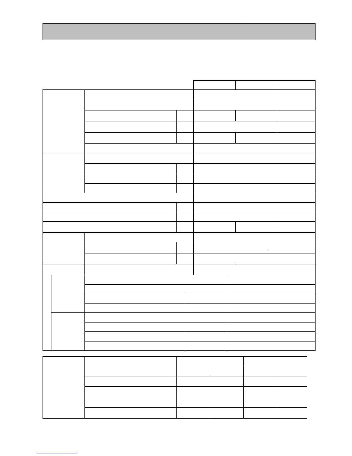
1.2 ELECTRICAL PARTS SPECIFICATION
MR-FT35EH-C MR-FT46EH-C MR-FT51EH-C
Running capacitor
Capillary tube
Dehydrant Molecular sieve
Refrigerant R600a
Model
Type
Input
Revolution
Model
Type
Input
Revolution
Dial position ON OFF OPEN SHUT
Warmer
o
C
-13.1 -16.1 3.9 2.9
Normal
o
C
-18.8 -21.8 2.4 1.4
Colder
o
C
-23.6 -26.6 -3.0 -4.0
4(Current limiter)
Running current (A.T. : 30 ºC)
A
Heater Defrost heater
Defrosting control
mm.
g
g
Defrosting timer
Defrost finish
Thermal fuse
Current
Motor protector
Model
Ambient temperature
Time
0.78 0.81
0.83
1.8 X 0.65 X 2350
9
Compressor
Model
Power supply
Rated input W
o
C
Sec.
A
Starting current
Winding resistance (A.T. : 20 oC)
Control board
Thermister 14 +
1.5
73
A
12.4
W
MM3-71CCY
o
C
o
C
FBA12J12VXC
DC brushless
1.44 (12V DC)
1450
(12V DC)
25
16 MAX
17.0
4
m
F 400VAC
81 W
(110V 150W)
7
6
W
(110V 160W)
MR-FT35EH-C
MR-FT46EH-C
MR-FT51EH-C
109 108 112
EEI91E13DCH
110V 60Hz
Machine
Chamber
W
r.p.m
W
r.p.m
4.2 (12V DC)
2300
(12V DC)
4715JL04WS16G51
DC brushless
Temperature control
Thermistor R
Freezer
Refrigerator
Thermistor F
73 82
85
Fan motor
Freezer
2

Unit : mm
MR-FT35EH-C
2
OUTLINES AND DIMENSIONS
PLUG CORD LENGTH
REQUIRED SPACE FOR INSTALLATION
3

Unit : mm
MR-FT46EH-C
PLUG CORD LENGTH
REQUIRED SPACE FOR INSTALLATION
629
795
4

Unit : mm
MR-FT51EH-C
PLUG CORD LENGTH
REQUIRED SPACE FOR INSTALLATION
629
795
5
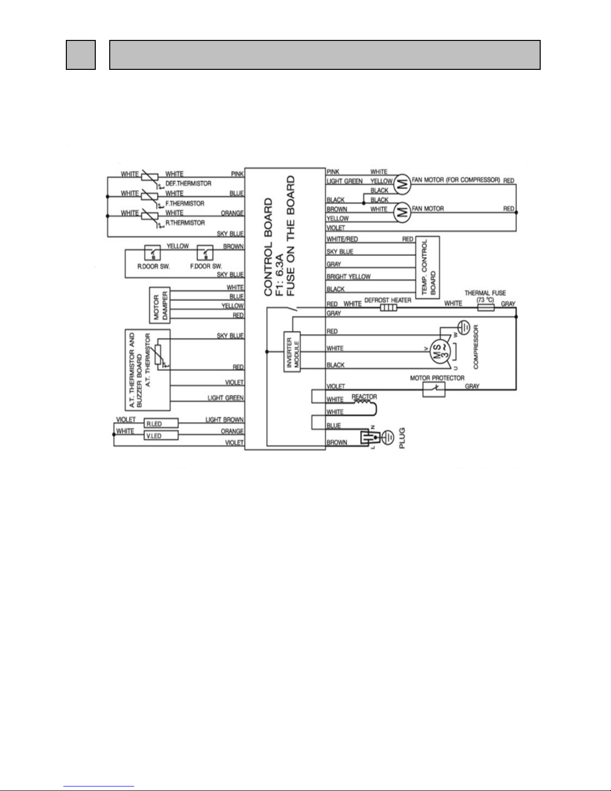
MR-FT35EH-C
MR-FT46EH-C (SKELETON WIRING DIAGRAM)
MR-FT51EH-C
3
WIRING DIAGRAM
6

7
MR-FT35EH-C
4
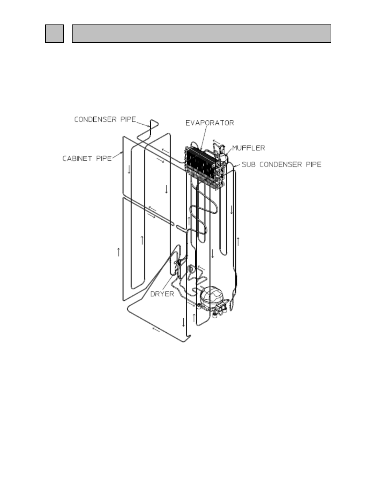
REFRIGERANT CIRCUIT
8

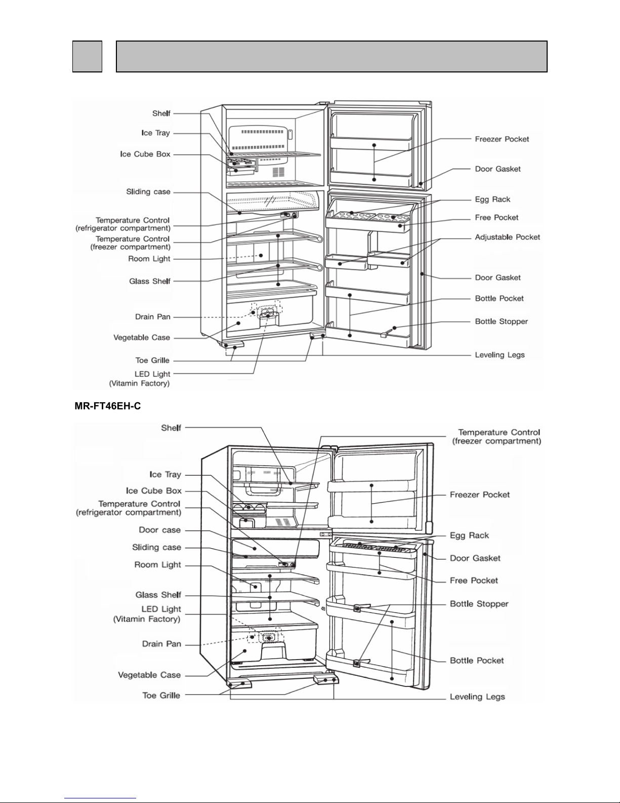
MR-FT46EH-C
MR-FT51EH-C
9
MR-FT35EH-C
MR-FT46EH-C
5
NAME OF PARTS
10
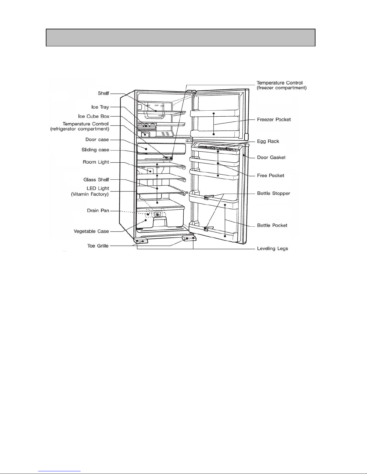
MR-FT51EH-C
11

6.1) TROUBLE CRITERION OF MAIN PARTS
MR-FT35EH-C MR-FT46EH-C MR-FT51EH-C
Measure the resistance with a tester.
(Ambient temperature:Room temperature 15oC ~ 25oC)
Open
Close
Opened (
W
)
Measure the resistance with a tester.(Ambient temperature:Room temperature 15oC ~ 25oC)
Measure the resistance with a tester.(Ambient temperature:Room temperature 15
o
C ~ 25oC)
Machine
chamber fan
motor
In the machine
chamber at the
rear side of the
frame.
Less than 1W
Motor
damper for
refrigerator
compartment
In the control
panel
of the refrigerator
compartment.
Normal
Abnormal
(faulty)
Winding
(Blue-White,
Red-Yellow)
415 W (Approx.)
Open ( W ) or
short circuit
(0W)
chamber at the
61 + 8o C
rear side of
Measure the resistance with a tester.(Ambient temperature:Room
temperature 15
o
C ~ 25oC)
the frame
Normal
Abnormal(faulty)
Winding
(Black-White)
(White-Red)
(Red-Black)
12.4 W
(20 ºC)
Opened ( W ) or
short circuit (0W)
Motor
protector
Compressor in
Model
MM3-71CCY
the machine
Connected Point
100 + 5o C
Rated current
A
0.84/1.10 (27/37 rps) the frame
Normal
Abnormal
(faulty)
the machine
Rated input
W
35.1/48.7(27/37 rps) chamber at the
Starting current
A
4.0 rear side of
6
TROUBLE SHOOTING
Components
/ Part Name
Check Method and Criterion
Parts Mounted
Position
Compressor
Compressor in
Model
EEI91E13DCH
Model
4715JL04WS16G51
Type
DC brushless
Normal
Abnormal (faulty)
Between 3 - 1 (GND
and Vcc): About 25kW
Between 3-1 : open(
W ) or
between 2-1 : short ( 0
12

In fan grille of the
freezer compartment.
Measure the resistance with a tester.(Ambient temperature:Room temperature 15oC ~ 25oC)
In the drip tray under
the evaporator of the
Measure the resistance with a tester.
freezer compartment
(Ambient temperature:Room temperature 15oC ~ 25oC)
Resistance measured under
Defrost thermistor
the ambient temperature from
(kW)
at the muffler
-50: to +50:
of evaporator
in freezer compartment.
1. 200" to 500k"
............normal
Freezer thermistor at
2. Out of the above range
fan grille of freezer
............abnormal
compartment.
Out air thermistor
under hinge cover
Thermistor Check Procedure
Thermistor resistance will vary
with the change of temperature.
Take the temperature around the thermistor,
and then measure resistance using a tester.
The relation of resistance and temperature is as shown on
the above graph.
Thermistor
MR-FT35EH
MR-FT46EH,FT51EH
331Ω (Approx.)
3
53Ω (Approx.)
Defrost
Heater
DC brushless
Model
Type
Model refrigerator
Rated input
Operation method
Abnormal (faulty)
Normal
Between 3 - 1 (GND
and Vcc): About 12kW
MR-FT35EH MR-FT46EH,FT51EH
Normal
Refrigerator
fan motor
Check Method and Criterion
Parts Mounted Position
Components/
Part Name
FBA12J12VXC
Between 3-1 : open( ¥ W )
or
between 3-4 : short ( 0 W)
150 W (110V) 160 W (110V)
Power ON after defrosting (14 ± 1.5ºC or more)
Abnormal (faulty)
Opened ( ∞ Ω )
Resistance
-20
20 30
-10
0
10
30
20
15
10
5
0
25
35
Thermistor resistance valves against
temperature
Temperature
Outside air thermistor
Freezer
thermistor,
Defrost
thermistor
Inner
thermistor
13

6.2 TEST POINT DIAGRAM OF MAIN CONTROL BOARD
14

MR-FT35EH,MR-FT46EH,MR-FT51EH
6.3 LED trouble display and check point.
1) Trouble is indicated by the blinking number of self-check LED(Red color) which locate
at near dial of control panel(The detail picture as shown in right side.)
The blinking number of self-check LED specifies the trouble which has occurred.
LED repeats to blinks as many times as the number specified for each trouble cycle.
Rule for convert error code from LED to numerical data as below :
- For ten's place, LED will light for 0.9s.(Long light period) - Time period while LED off inside its cycle was 0.3 s
- For ones' place, LED will light for 0.3s.(Short light period) - Time period while LED off between each cycle was 3 s
Example of error code 12 as shown in below timeline.
Table shown error code
Tens'
place
Ones'
place
0 2 Compressor turns OFF.
1 1
2. Check the resistance of thermistor.
>Replace.
1 2
2. Check the resistance of thermistor.
>Replace.
1 3
2. Check the resistance of thermistor.
>Replace.
1 8
3 1
>Replace.
3 2
2.Check BOX FAN operation. >Replace.
Trouble of BOX FAN When motor doesn’t rotate even though
power is on
1.Connector CN9S and CN5D
on control board, fan motor 4-pin
wire to wire connector
>Repair the
contact failure.
* 3 minutes later, the fan motor is
reactivated to be checked.
* Until the fan motor gets to operate
correctly, the buzzer sounds every time
the door is closed.
Trouble of freezer fan
motor
When motor doesn’t rotate even though
power is on
1.Connector CN9S and CN5D
on control board, fan motor 4-pin
wire to wire connector
2.Check fan motor operation.
>Repair the
contact failure.
* 3 minutes later, the fan motor is
reactivated to be checked.
* Until the fan motor gets to operate
correctly, the buzzer sounds every time
the door is closed.
Trouble of refrigerator
thermistor
When there is a short or open circuit in
the
F-room thermistor.
1. Connector CN9S on control board,
4-pin wire to wire connector
>Repair the
contact failure.
Synchronize the open/close status of R
damper with that of compressor
Trouble of outside air
thermistor
(NOTE 2)
When there is a short or open circuit in
the outside air thermistor.
>Replace
OPERATION
PCB
Control it by refering to outside temp at
25 ºC.
After compressor off, the compressor
repeats 30-minute ON and 20-minute
OFF
Trouble of defrost
thermistor
When there is a short or open circuit in
the defrost thermistor.
1. Connector CN9S on control board,
4-pin wire to wire connector
>Repair the
contact failure.
The defrost heater won’t be turned ON.
Communication
error of inverter
A commutation error occurs between
refrigerator control circuit and inverter
control circuit in control board. (They
do not transmit and receive data for 10
seconds.)
>Replace the
control board
Trouble of freezer
thermistor
When there is a short or open circuit in
the
refrigerator compartment thermistor.
(NOTE2)
1. Connector CN9S on control
board,
>Repair the
contact failure.
ERROR CODE
Trouble Detecting method Check point How to fix Control
LED self
check
Tens' place Ones' place Tens' place Ones' place
0.9 s 0.3 s 0.3 s 0.3 s 0.3 s 3 s 0.9 s 0.3 s 0.3 s 0.3 s 0.3 s
1 CYCLE 1 CYCLE
LED ON
LED OFF
15

Tens'
place
Ones'
place
3 4
5 0
5 1
5 2
5 3
5 5
5 6
5 7
The setting of Self Mode Check will be displayed and blinks during or Self Mode Check operation.
SHORT or OPEN circuit of thermister.
When the resistance is ∞ Ω, the circuit is deemed open-circuited.
When the resistance is 0 Ω , the circuit is deemed short-circuited.
The error codes E50 to E55are not displayed even if those abnormalities occur when power is turned on.
Therefore, be sure to perform self check mode operation in order to check if any abnormality
indicated by these error codes occurs.
If those errors still continue for 1 minute after the restart, E56 will be displayed again.
(NOTE4)
(NOTE5)
(NOTE1)
(NOTE2)
Inverter drive module
abnormality
The overcurrent error is detected before
starting the compressor (failure of the IC
in the inverter drive module)
>Replace
the control board.
An attempt to restart the compressor is
repeated every 3 minutes
Trouble of control board
(EEPROM related trouble)
(NOTE4)
EEPROM (IC11M)
accumulates data necessary for control.
• The data are not input accurately.
• The microcomputer cannot read the
data.
>Replace the
control board.
If abnormality occurs when power is
turned on, the compressor is stopped
for 10 minutes.
When abnormality occurs during
normal operation, the compressor
keeps operating.
Defective wiring
connecting or trouble of
control board
The errors E50 to E53 keep occurring
over one and a half hour. (The situation,
which compressor cannot be operated,
continues.)
• The error display starts after
the error is determined as E56.
• The error display continues
until defrosting starts or cooling
operation gets back to normal. (The
error display does not disappear by
unplugging and plugging the power
cord.)
(Note5)
• An attempt to restart the compressor
is repeated every 3 minutes.
Trouble of bus-bar voltage
• The range of bus-bar voltage is not
approx. 50 ~ 340 VDC
Trouble of inverter
software reset function
• The inverter driving software
malfunctions.
Trouble of startup,
synchronization or
overcurrent detection
(NOTE4)
• There is no current at compressor
startup.
• The phase current exceeds 5.5 A at
compressor startup.
• The phase current exceeds 3.3 A
during compressor operation.
•A current of 5.3 A or more runs into the
bus-bar of control board.
The compressor is stopped and
reactivated 10 minutes later
Refer to “Compressor does not operate” topic
Refer to “Compressor does not operate” topic
Clogging of refrigerant
pipe or trouble relatedto
compressor.
(T0: Defrost thermistor temperature at
power input, T1: Defrost thermistor
temperature when 15 minutes have
passed from the power input)
• When the difference between T0 and
T1 is T0 ≦ T1
Check the compressor and the pipe. When cooling operation returns to
normal condition, the display of error
code disappears.
Trouble of inverter circuit
(NOTE4)
• There is any trouble in the circuit
which detects current of compressor
>Replace the
control board.
ERROR CODE
Trouble Detecting method Check point How to fix Control
16

6.4 Importance detail of fault analysis
6.4.1 Flow chart of self - check
1)Self - check monitor circuit
For show the fault condition of refrigerator and clarify point. Therefore, self - check monitor control is provided
that are able to monitor No. of blinking condition with electric circuit and electric part . Before disconnect power plug please
confirm LED self - check .
Caution
1.As the part list below couldn't analysis by self - check , then
please check by reference to trouble shooting page.
- Dilapidation of door switch ,refrigerator room and freezer room.
- Dilapidation of compressor and fan motor .
2.If have malfunction when supply the power . Compressor and
fan motor will not operate 20 minutes.
2)
Interval of self check analysis
- Troubles of thermistor : will check always.
- Trouble of defrost heater : will just analyse during defrost display only.
(The period checking will analyse the defrost circuit after connect the plug 2 hours )
Refrigerator plug
connect?
Connect power plug
Self - check
Mal Function Display
(No .of blinking)
No change on display
Normal operation
Check the fault point as
malfunction list
Disconnect power plug
Repair the macfunction cause
Connect power plug
No
Yes
Yes
No
17

6.4.2 LED for deodorition and bacteria eradication display
Install part point
Normal Use tester's diode range with swing meter during (-)-1 (+) of 2 PM connector by asking use
tester which have diode range ( )
Timing connect power
After compressor off 3 min. , after the defrost heater off 8 min during open the door ( max 5 min.)
Malfunction
LED will shine the violet
light with in timing hole
above.( right picture )
Use tester's diode range with swing meter during 2 (-)-1 (+) , and for make sure which change
poles and observe must be not swing of short resistance ( 0
W
)
LED
18

19

Defrost heater and Drip tray
(6)
Photo 6 Lift up Evaporator and remove the Defrost
heater out of base after remove Heater cover plate
and Drip tray
Caution on assembly
1. Insert the Fan into the base of Fan motor's shaft,
check if the Fan rotates with your finger.
2. When inserted Drip tray to effect to slacken the
lead wire of Defrost heater in order to prevent water
from entering the glass tube.
3. Attach Defrost thermistor with Muffler and tighten
the binder.
2. Remove parts inside the Refrigerator room
(1) Remove Chilled case door and Slide chilled case ,
remove Glass shelves of refrigerator room , remove
the Control panel
(2)
Remove Lamp cover R from Catch
(Photo 8)
(3) Remove Screw (Photo 8) and Rivet (Photo 7) , pull
the Control panel with to right refrigerator wall.
(4)
Remove S-tape lam, Detach connector between
control panel and refrigerator wall.
(5) Remove Catch in left side (Photo 9) and right side of
Duct R assy, Remove Duct R assy (Photo 9)
(Duct damper setting inside Duct R assy)
(6)
Remove S-tape lam, Detach Temp control board
from Catch before Remove Temp control board from
lock socket, Remove Connector from Temp control
board
Remove LED attach assy after remove Lamp cover
(Photo 11,12)
(7) Remove Screw between LED attach assy and Control
panel (Sub) and unlock Catch before remove LED
board from LED attach socket.
(*Remark : LED attach assy is assembling between
LED board attach and LED light board)
OPERATING PROCEDURE
PHOTOS
Photo 7
Photo 6
Defrost heater
Heater roof
Drip tray
Evaporator Def thermistor
Rivet
Catch
Screw
Control panel
Lamp cover R
Control panel (Sub)
Catch
Photo 8
Duct R assy
Control panel
Temp control board
Photo 11
S-tape lam
S-tape lam
Catch (Left)
Connector
(สําหร ับรุ่น
MR-
Screw
Screw
LED attach
assy(Back)
LED attach
assy(ด้านหลัง)
Catch
Connector
Catch
LED attach
assy(Front)
(For model
MR-FT35EH)
LED attach
assy(Front)
LED light
board
Catch
Connector
Photo 12
LED light
board
Photo 9
Photo 10
(For model MRFT46EH,FT51EH)
LED attach
assy(Back)
20

Removing vitamin up assy
(8)
Remove the Vitamin up attach.
(Photo 13)
(9)
Remove the 2 screw and remove the vitamin up.
(Photo 14)
Remove the Elect cover
(10)
Take out screw (2 points)
(Photo 15)
(11) Take out screw (2 points)at left side and right side
of electric box cover ,then pull the electric box cover
(Photo 16)
OPERATING PROCEDURE PHOTOS
Welding point at back side of refrigerator
(For model MR-FT46EH,FT51EH)
CHARGE PIPE
DRYER
DISCHARGE PIPE
COMPRESSOR
B
B
BINDER
(For model MR-FT35EH)
SUCTION PIPE
Screws
Photo 14
Photo 13
Vitamin up
Vitamin up
attach
Screw
Screw
Photo 15
Photo 16
Connector
Connector
Catch
Elect cover
Refcon assy
Elect attach
Catch
21

DOOR, BODY PARTS
MR-FT35EH-C
8 PARTS LIST
2
3
4
5
6
8
12
11
13
9
10
1
7
22

DOOR , BODY PARTS
Q'TY/UNIT
MR-FT35EH-C
sw
1 KIEL76131 <G> FREEZER POCKET
1
2 KIEL76131 <G> FREEZER POCKET
1
3 KIE401115 <G> EGG RACK
2
4 KIEL75118 <G> FREE POCKET
1
5 KIEL75159 <G> ADJUST POCKET
2
6 KIEL76124 <G> BOTTLE POCKET
1
7 KIEL76124 <G> BOTTLE POCKET
1
8 KIEH88143 <G> BOTTLE STOPPER
1
9 KIEYE1001 <G> DOOR F
1
10 KIEH79111 <G> MAGNET GASKET ASSY (F)
1
11 KIEYE1000 <G> DOOR R
1
12 KIEH79110 <G> MAGNET GASKET ASSY (R)
1
13 KIEG05741 <G> CATCHER
2
14 KIEY82031 <G> BADGE ASSY
1
ABBREVIATION
ENCIRCLED PART NUMBER ARE NOT SHOWN IN THE FIGURES.
Remark
- Country code : C = TAIWAN
- Color code : SW = SNOWY WHITE
PRICE/PIECE
(US$-FCA)
NO. PART NO. PART NAMESRoHS SPEC
F
R
FREEZER ROOM
REFRIGERATOR ROOM
23

ACCESSORY PARTS
MR-FT35EH-C
24

ACCESSORY PARTS
Q'TY/UNIT
MR-FT35EH-C
sw
1 KIEWD0662 <G> BELL MOUTH 1
2 KIET73663 <G> FAN GRILLE
PLASTIC PART ONLY
1
3 KIEWD0450 <G> ICE CORNER ASSY 1
4 KIEWD0665 <G> DUCT R ASSY 1
5 KIEL75411 <G> SLIDE CHILLED CASE 1
6 KIEWD0850 <G> CONTROL PANEL
PLASTIC PART ONLY
1
7 KIEHJ3305 <G> THERMO DIAL (R) 2
8 KIEY54853 <G> CONTROL PANEL (SUB) 1
9 KIEL75470 <G> LAMP COVER (R) 1
10 KIEK66430 <G> GLASS SHELF ( R ) 3
11 KIEV68405 <G> VEGETABLE CASE 1
12 KIEWD0435 <G> DRAIN PAN 1
13 KIE805794 <G> CASTER SET 2
14 KIEH79326 <G> LEAD COVER F 1
15 KIER65705 <G> HINGE COVER 1
16 KIEP89701 <G> HINGE ASSY (UPPER) 1
17 KIEH79431 <G> CRYSTAL SHELF (F) 1
18 KIEL55440 <G> ICE TRAY 1
19 KIEG63487 <G> ICE BOX 1
20 KIEWD0746 <G> STOPPER HINGE 2
21 KIEMQ4703 <G> HINGE ASSY (MIDDLE) 1
22 KIEV91418 <G> CHILLED CASE DOOR 1
23 KIEWD1795 <G> CASTER ASSY RH 1
24 KIEWD0795 <G> CASTER ASSY LH 1
25 KIEWD1460 <G> ADJUST FOOT RH 1
26 KIEWD0460 <G> ADJUST FOOT LH 1
27
KIEY86730 <G> KICK PLATE RH 1
28 KIEY82730 <G> KICK PLATE LH 1
29
KIEWD0652 <G> COMP COVER ASSY
ATTACH AT LOWER SIDE OF
BEHIND REF
1
30
KIEYE1663 <G> FAN GRILLE ASSY
INCLUDE ALL OF ELECTRICAL PART
& PLASTIC PART
1
31
KIEWD0449 <G> ICE CORNER SUPPORT
ATTACH AT BETWEEN ICE
CORNER LH & RH
1
32 KIEYE1858 <G> CONTROL PANEL ASSY
INCLUDE ALL OF ELECTRICAL PART
& PLASTIC PART
1
ABBREVIATION
ENCIRCLED PART NUMBER ARE NOT SHOWN IN THE FIGURES.
NO. PART NO. RoHS PART NAMES SPEC
PRICE/PIECE
(US$-FCA)
F
R REFRIGERATOR ROOM
FREEZER ROOM
25

ELECTRICIAL PARTS AND UNIT PARTS
MR-FT35EH-C
26

ELECTRICIAL PARTS AND UNIT PARTS
Q'TY/UNIT
MR-FT35EH-C
sw
1 KIEY82326 <G> ELECT COVER ASSY 1
2 KIEWD0367 <G> REACTOR 1
3 KIEYE1339 <G> REFCON ASSY 1
4 KIEYE1336 <G> THERMISTOR & FUSE ASSY 1
5 KIEYE1354 <G> PLUG CORD ASSY 1
6 KIEMQ4995 <G> EVAPORATOR 1
7 KIEWD0537 <G> HEATER ROOF 1
8 KIEYE1392 <G> DEFROST HEATER ASSY 110V 150W 1
9 KIEHJ4682 <G> DUCT DAMPER 1
10 KIEWD0313 <G> THERMITOR ( R ) ASSY 1
11 KIEH61399 <G> FILTER 1
12 KIEWD0980 <G> DRYER XH-9,9GR 1
13 KIEK48369 <G> VITAMIN UP ATTACH 1
14 KIEK48379 <G> VITAMIN UP 1
15 KIEWD1662 <G> FAN ATTACH 1
16 KIEP89325 <G> OUT FAN MOTOR ASSY 4715JL04WS16G51 1
17 KIEB66378 <G> THERMISTOR (F) 1
18 KIEMQ4312 <G> THERMISTOR (DEF) 1
19 KIEV61374 <G>
BUZZER BOARD & THERMISTOR (A.T.)
1
20 KIEMQ4320 <G> FAN MOTOR FBA12J12VXC 1
21 KIEWD0538 <G> DRIP TRAY 1
22 KIEMQ4363 <G> LAMP SWITCH 2
23 KIEP64382 <G> TEMP CONTROL BOARD 1
24 KIEWD0360 <G> LED LIGHT BOARD ASSY 1
25 KIEWD0361 <G> LED BOARD ATTACH 1
26 KIEWD0341 <G> PROTECTOR COVER 1
27 KIEWD0340 <G> MOTOR PROTECTOR MM3-71CCY 1
28 KIEWD0277 <G> COMPRESSOR EEI91E13DCH 1
29 KIE902735 <G> U WASHER 3
30 KIEHJ3797 <G> RUBBER MOUNT 4
31 KIEN43919 <G> MINUS ION 1
32 KIEWD0327 <G> ELECT ATTACH
PLASTIC PART ONLY
(ATTACH WITH REFCON
ASSY)
1
ABBREVIATION
ENCIRCLED PART NUMBER ARE NOT SHOWN IN THE FIGURES.
NO. PART NO. RoHS PART NAMES SPEC
PRICE/PIECE
(US$-FCA)
FRFREEZER ROOM
REFRIGERATOR ROOM
DEF DEFROST
27

PACKING PARTS
MR-FT35EH-C
NO STEP ON
1
C.F.B B OX ASSY
9
C.F.B TOP COVER
6
DF CORUGATED BOARD
5
PACKING COVER
8
C.F.B PALL ET
7
BOTTOM CUSHION
4
INSU TOP CUSHION (S)
3
INSU TOP CUSHION
(L)
2
TOP CUSHION
28

PACKING PARTS
Q'TY/UNIT
MR-FT35EH-C
sw
1 KIEYE1970
<G>
C.F.B BOX ASSY 1
2 KIEWD0979 <G> TOP CUSHION 1
3 KIEWD0972 <G> INSU TOP CUSHION (L) 1
4 KIEWD1972 <G> INSU TOP CUSHION (S) 2
5 KIEG55973 <G> PACKING COVER 1
6 KIEH79971 <G> DF CORUGATED BOARD 1
7 KIEWD0978 <G> BOTTOM CUSHION 1
8 KIEWD0974 <G> C.F.B PALLET 1
9 KIEH79975 <G> C.F.B TOP COVER 1
NO. PART NO. RoHS PART NAMES SPEC
PRICE/PIECE
(US$-FCA)
29

DOOR , BODY PARTS
MR-FT46EH-C
MR-F51EH-C
30

DOOR , BODY PARTS
MR-FT46EH-C MR-FT51EH-C
SW SW
1
KIEV80131 <G> FREEZER POCKET 2 2
2
KIE401115 <G> EGG RACK 2 2
3
KIEV80118 <G> FREE POCKET ( S ) 1 1
4
KIEV80119 <G> FREE POCKET ( L ) 1 2
5
KIEV80124 <G> BOTTLE POCKET 2 2
6
KIEH88143 <G> BOTTLE STOPPER 2 2
7
KIEY82001 <G> DOOR F 1 1
8
KIEV80111 <G> MAGNET GASKET ASSY ( F ) 1 1
KIEY82000 <G> 1
KIEY86000 <G> 1
KIEV80110 <G> 1
KIEV82110 <G> 1
11
KIEY82031 <G> BADGE ASSY 1 1
RECOMMED PART NO. 7, 8, 9, 10
PART NO. THAT ARE CIRCLED ARE NOT SHOWN IN THE FIGURES
ABBREVIATION
Remark
- Country code : C = TAIWAN
- Color code : SW = SNOWY WHITE
PRICE/PIECE
(US$-FCA)
9
DOOR R
10
MAGNET GASKET ASSY ( R )
NO. PART NO.
RoHS
PART NAME SPEC
Q'TY/UNIT
FRFREEZER ROOM
REFRIGERATOR ROOM
31

ACCESSORY PARTS
MR-FT46EH-C
MR-FT51EH-C
32

ACCESSORY PARTS
MR-FT46EH-C MR-FT51EH-C
SW SW
1
KIEWD6662 <G> BELL MOUTH
1 1
2
KIEMR7492 <G> COVER GRILLE
1 1
3
KIEPM7663 <G> FAN GRILLE
1 1
4
KIEG05450 <G> ICE CORNER
1 1
KIEWD6665 <G>
1
KIEWD9665 <G>
1
6
KIEWD6850 <G> CONTROL PANEL
1 1
7
KIEHJ3305 <G> THREMO DIAL ( R )
2 2
8
KIEC02411 <G> SLIDE CHILLED CASE
1 1
KIEWD6853 <G>
1
KIEWD9853 <G>
1
KIEL85470 <G>
1 1
KIEL87470 <G>
11
KIEL85430 <G> GLASS SHELF ASSY ( R )
1 1
KIEC02685 <G>
1
KIEC08685 <G>
1
13
KIEL85430 <G> GLASS SHELF ASSY ( R )
1 2
14
KIE805794 <G> CASTER SET
2 2
15
KIEWD0435 <G> DRAIN PAN
1 1
16
KIEC02789 <G> SHAFT ROLLER
2 2
17
KIEG05326 <G> COVER F
1 1
18
KIER65705 <G> HINGE COVER (RH)
1 1
19
KIEP89701 <G> HINGE ASSY (UPPER) RH
1 1
20
KIEWD6431 <G> CRYSTAL SHELF ( F )
1 1
21
KIEME5438 <G> ICE CORNER TRAY
1 1
22
KIEL85440 <G> ICE TRAY
1 1
23
KIEC02467 <G> ICE BOX
1 1
24
KIEMQ4703 <G> HINGE ASSY (MIDDLE) RH
1 1
25
KIEWD0746 <G> DOOR STOPPER (F/R) RH
2 2
26
KIEV80418 <G> CHILLED CASE DOOR
1 1
27
KIEH88429 <G> GLASS SHELF ( RV )
1 1
28
KIEV80405 <G> VEGETABLE CASE
1 1
29
KIEG05788 <G> ROLLER BOX
2 2
30
KIEG05798 <G> ROLLER
2 2
31
KIEWD1795 <G> CASTER ASSY RH
1 1
32
KIEWD0795 <G> CASTER ASSY LH
1 1
33
KIEWD1460 <G> ADJUST FOOT RH
1 1
34
KIEWD0460 <G> ADJUST FOOT LH
1 1
35
KIEY86730 <G> KICK PLATE RH
1 1
36
KIEY82730 <G> KICK PLATE LH
1 1
37
KIEWD6652 <G>
COMP COVER ASSY
Attach at lower side of behind ref 1 1
38
KIEYE2663 <G>
FAN GRILLE ASSY
Include all of electrical part & plastic part 1 1
KIEYE2858 <G>
1
KIEYE3858 <G>
1
ABBREVIATION
ENCIRCLED PART NUMBER ARE NOT SHOWN IN THE FIGURES.
Include all of electrical part & plastic part
10
LAMP COVER ( R )
12
DUCT R (SUB)
39
CONTROL PANEL ASSY
PRICE/PIECE
(US$-FCA)
5
DUCT R ASSY
9
CONTROL PANEL ( SUB )
NO. PART NO.
RoHS
PART NAME SPEC
Q'TY/UNIT
FRFREEZER ROOM
REFRIGERATOR ROOM
R.V. BETWEEN REFRIGERATOR ROOM AND VEGETABLE ROOM
33

ELECTRICIAL PARTS AND UNIT PARTS
MR-FT46EH-C
MR-FT51EH-C
34

ELECTRICIAL PARTS AND UNIT PARTS
MR-FT46EH-C MR-FT51EH-C
SW SW
1 KIEY82326
<G> ELECT COVER ASSY
1 1
2 KIEWD0367
<G> REACTOR
1 1
3 KIEYE2339
<G> REFCON ASSY
1 1
4 KIEYE2336
<G> THERMAL FUSE ASSY ( DEF )
1 1
5 KIEYE1354
<G> PLUG CORD ASSY
1 1
6 KIENB1995
<G> EVAPORATOR
1 1
7 KIEWD6537
<G> HEATER ROOF
1 1
8 KIEYE2392
<G> DEFROST HEATER ASSY
1 1
9 KIEHJ4682
<G> DUCT DAMPER
1 1
10 KIEWD6313
<G> THERMITOR ( R ) ASSY
1 1
11 KIEH61399
<G> FILTER
1 1
12 KIEN43919
<G> MINUS ION
1 1
13 KIEWD0980
<G> DRYER XH-9,9GR
1 1
14 KIEK48369
<G> VITAMIN UP ATTACH
1 1
15 KIEK48379
<G> VITAMIN UP
1 1
16 KIEWD7662
<G> FAN ATTACH
1 1
17 KIEP89325
<G> OUT FAN MOTOR ASSY 4715JL04WS16G51
1 1
18 KIEB66378
<G> THERMISTOR ( F )
1 1
19 KIEMQ4312
<G> THERMISTOR ( DEF )
1 1
20 KIEV61374
<G> BUZZER BOARD & THERMISTOR (A.T.)
1 1
21 KIEMQ4320
<G> FAN MOTOR FBA12J12VXC
1 1
22 KIEB66538
<G> DRIP TRAY
1 1
23 KIEMQ4363
<G> LAMP SWITCH
2 2
24 KIEP64382
<G> TEMP CONTROL BOARD
1 1
25 KIEW73360
<G> LED LIGHT BOARD ASSY
1 1
26 KIEWD6361
<G> LED BOARD ATTACH
1 1
27 KIEWD0341
<G> PROTECTOR COVER
1 1
28 KIEWD0340
<G> MOTOR PROTECTOR MM3-71CCY
1 1
29 KIEWD0277
<G> COMPRESSOR EEI91E13DCH
1 1
30 KIE902735
<G> U WASHER
4 4
31 KIEHJ3797
<G> RUBBER MOUNT
4 4
32 KIEWD6990
<G> CONDENSER
1 1
33 KIEWD0327
<G> ELECT ATTACH
PLASTIC PART ONLY
(ATTACH WITH REFCON
ASSY)
1 1
ABBREVIATION
ENCIRCLED PART NUMBER ARE NOT SHOWN IN THE FIGURES.
PRICE/PIECE
(US$-FCA)
NO. PART NO.
RoHS
PART NAME SPEC
Q'TY/UNIT
F
DEF
FREEZER ROOM
DEFROST
35
110V 160W

PACKING PARTS
MR-FT46EH-C
MR-FT51EH-C
NO STEP ON
1
C.F.B B OX ASSY
9
C.F.B TOP COVER
6
SIDE CUSHION
5
PACKING COVER
8
C.F.B PALL ET
7
BOTTOM CUSHION
4
INSU TOP CUSHION (S)
3
INSU TOP CUSHION (L)
2
TOP CUSHION
36

PACKING PARTS
MR-FT46EH-C MR-FT51EH-C
SW SW
KIEYE2970 <G> 1
KIEYE3970 <G> 1
2
KIEWD6979 <G> TOP CUSHION 1 1
3
KIEWD6972 <G> INSU TOP CUSHION (L) 1 1
4
KIEWD7972 <G> INSU TOP CUSHION (S) 2 2
5
KIEG55973 <G> PACKING COVER 1 1
6
KIEG55971 <G> SIDE CUSHION 1 1
7
KIEWD6978 <G> BOTTOM CUSHION 1 1
8
KIEWD6974 <G> C.F.B PALLET 1 1
9
KIEWD6975 <G> C.F.B TOP COVER 1 1
PRICE/PIECE
(US$-FCA)
1
C.F.B BOX ASSY
NO. PART NO.
RoHS
PART NAME SPEC
Q'TY/UNIT
37

KANG YONG ELECTRIC PUBLIC COMPANY LIMITED.
67 Moo 11, Bangna-Trad Road Km.20, Bangplee, Samutprakarn 10540 Thailand.
TEL : 0-2337-2900 FAX : 0-2337-2954
http:www.mitsubishi-kye.com
Printing Date : September 2015
e-mail: information@kye.meap.com
 Loading...