

Page 1

General-Purpose AC Servo
MODEL
MR-E- A/AG
INSTRUCTION MANUAL
B
Page 2
Safety Instructions
(Always read these instructions before using the equipment.)
Do not attempt to install, ope rate, maint ain or inspect the servo amplif ier and servo m otor until you hav e read
through this I nstruction M anual, Insta llation guid e, Servo motor Instructio n Manual and appen ded docum ents
carefully and can us e th e equ i pment correctly. D o no t us e t he s er vo amplifier and servo motor un ti l you have a
full knowledge of the equipment, safety information and instructions.
In this Instruction Manual, the safety instruction levels are classified into "WARNING" and "CAUTION".
Indicates that incorrect handling may cause hazardous conditions,
WARNING
CAUTION
Note that the CAUTION level may lead to a serious consequence according to conditions. Please follow the
instructions of both levels because they are important to personnel safety.
What must not be done and what must be done are indicated by the following diagrammatic symbols:
resulting in death or severe injury.
Indicates that incorrect handling may cause hazardous conditions,
resulting in medium or slight injury to personnel or may cause physical
damage.
: Indicates what must not be done. For example, "No Fire" is indicated by
: Indicates what must be done . F o r exa mple , grou nd ing is in di cat ed by
In this Instruction Manual, instructions at a lower level than the above, instructions for other functions, and so
on are classified into "POINT".
After reading this installation guide, always keep it accessible to the operator.
.
.
A - 1
Page 3
1. To prevent electric shock, note the following:
WARNING
Before wiring or inspection, switch power off and wait for more than 10 minutes. Then, confirm the voltage
is safe with voltage tester. Otherwise, you may get an electric shock.
Connect the serv o a mpl i fie r and se rvo mot o r to grou nd .
Any person who is involved in wiring and inspection should be fully competent to do the work.
Do not attempt to wire the servo amplifier and servo motor until they have been installed. Otherwise, you
may get an electric shock.
Operate the switches with dry hand to prevent an electric shock.
The cables should not be damaged , stressed, loaded, or pinched. Othe rwi se, you may get an ele ctric shoc k.
2. To prevent fire, note the following:
CAUTION
Do not install the servo amplifier, servo motor and regenerative brake resistor on or near combustibles.
Otherwise a fire may cause.
When the servo amplifier has become faulty, switch off the main servo amplifier power side. Continuous
flow of a large current may cause a fire.
When a regenerative brake resistor is used, use an alarm signal to switch main power off. Otherwise, a
regenerative brake transistor fault or the like may overheat the regenerative brake resistor, causing a fire.
3. To prevent injury, note the follow
CAUTION
Only the voltage specified in the Instruction Manual should be applied to each terminal, Otherwise, a
burst, damage, etc. may occur.
Connect the terminals correctly to prevent a burst, damage, etc.
Ensure that polarity ( , ) is correct. Otherwise, a burst, damage, etc. may occur.
During power-on or for some time after power-off, do not touch or close a parts (cable etc.) to the servo
amplifier heat sink, regenerative brake resistor, servo motor, etc. Their temperatures may be high and you
may get burnt or a parts may damaged.
During operation, never touch the rotating parts of the servo motor. Doing so can cause injury.
A - 2
Page 4
4. Additional instructions
The following instructions should also be fully noted. Incorrect handling may cause a fault, injury, electric
shock, etc.
(1) Transportation and installation
CAUTION
Transport the products correctly according to their weights.
Stacking in excess of the specified number of products is not allowed.
Do not carry the servo motor by the cables, shaft or encoder.
Do not hold the front cover to transport the servo amplifier. The servo amplifier may drop.
Install the servo amplifier in a load-bearing place in accordance with the Instruction Manual.
Do not climb or stand on servo equipment. Do not put heavy objects on equipment.
The servo amplifier and servo motor must be installed in the specified direction.
Leave specified clearances between the servo amplifier and control enclosure walls or other equipment.
Do not install or operate the servo amplifier and servo motor which has been damaged or has any parts
missing.
Provide adequate protection to prevent screws and other conductive matter, oil and other combustible
matter from entering the servo amplifier.
Do not drop or strike servo amplifier or servo motor. Isolate from all impact loads.
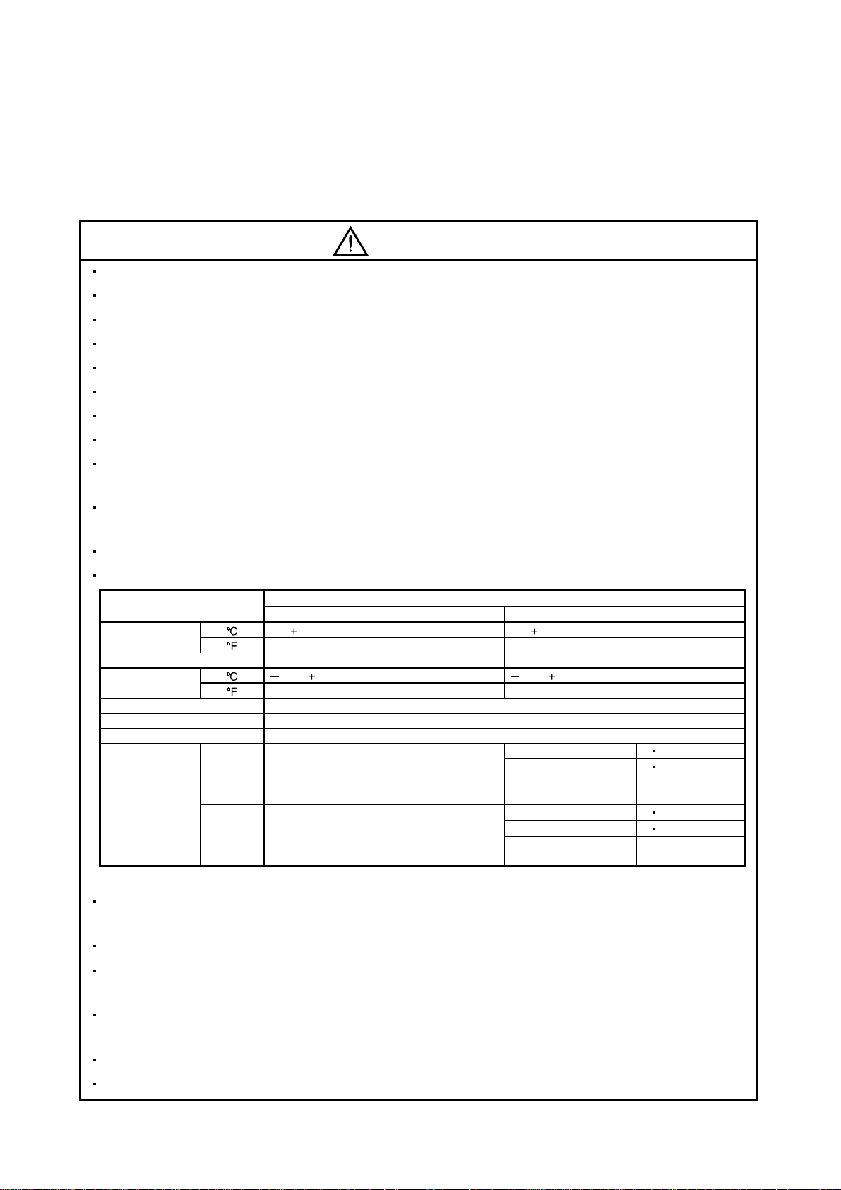
Use the servo amplifier and servo motor under the following environmental conditions:
Environment
Ambient
temperature
Ambient humidity 90%RH or less (non-condensing) 80%RH or less (non-condensing)
Storage
temperature
Storage humidity 90%RH or less (non-condensing)
Ambience Indoors (no direct sunlight) Free from corrosive gas, flammable gas, oil mist, dust and dirt
Altitude Max. 1000m (3280 ft) above sea level
(Note)
Vibration
Note: Except the servo motor with reduction gear.
[ ]0 to 55 (non-freezing) 0 to 40 (non-freezing)
[
] 32 to 131 (non-freezing) 32 to 104 (non-freezing)
[ ] 20 to 65 (non-freezing) 15 to 70 (non-freezing)
] 4 to 149 (non-freezing) 5 to 158 (non-freezing)
[
[m/s2] 5.9 or less
2
[ft/s
] 19.4 or less
Servo amplifier Servo motor
Conditions
HC-KFE Series X Y : 49
HC-SFE52 to 152 X Y : 24.5
HC-SFE202
HC-KFE Series X Y : 161
HC-SFE52 to 152 X Y : 80
HC-SFE202
X : 24.5
Y : 49
X : 80
Y : 161
Securely attach the servo motor to the machine. If attach insecurely, the servo motor may come off during
operation.
The servo motor with reduction gear must be installed in the specified direction to prevent oil leakage.
Take safety measures, e.g. provide covers, to prevent accidental access to the rotating parts of the servo
motor during operation.
Never hit the servo motor or shaft, especially when coupling the servo motor to the machine. The encoder
may become faulty.
Do not subject the servo motor shaft to more than the permissible load. Otherwise, the shaft may break.
When the equipment has been stored for an extended period of time, consult Mitsubishi.
A - 3
Page 5
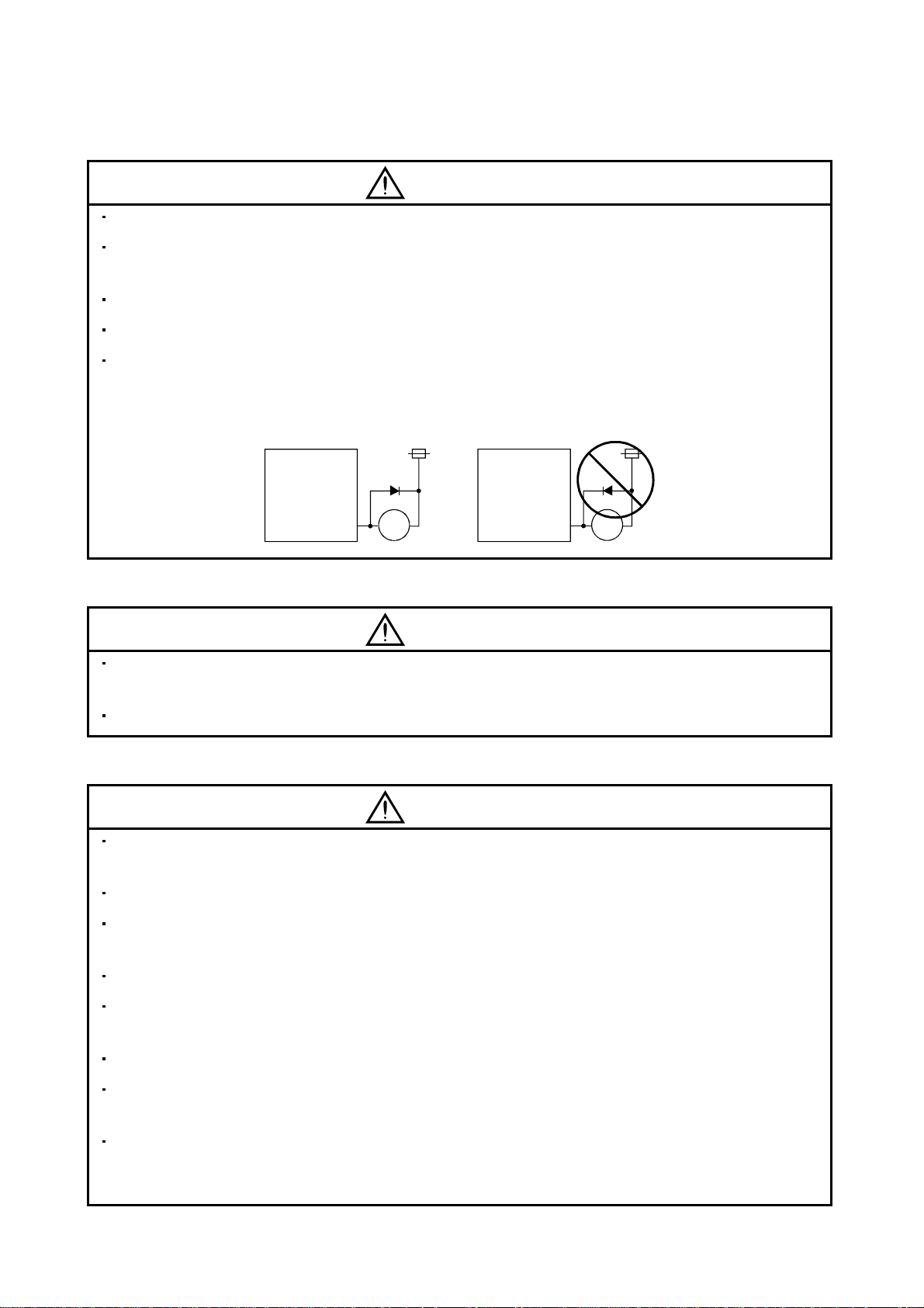
(2) Wiring
CAUTION
Wire the equipment correctly and securely. Otherwise, the servo motor may misoperate.
Do not install a power capacitor, surge absorber or radio noise filter (FR-BIF option) between the servo
motor and servo amplifier.
Connect the output terminals (U, V, W) correctly. Otherwise, the servo motor will operate improperly.
Do not connect AC power directly to the servo motor. Otherwise, a fault may occur.
The surge absorbi ng diode in stal le d on th e D C out pu t si gnal r el ay must be wi red in th e spe ci fie d di re ctio n .
Otherwise, the emergency stop and other protective circuits may not operate.
Servo
Amplifier
Control output
signal
External
24VDC
RA
Servo
Amplifier
Control output
signal
External
24VDC
RA
(3) Test run adjustment
CAUTION
Before operation, check the parameter settings. Improper settings may cause some machines to perform
unexpected operation.
The parameter settings must not be changed excessively. Operation will be insatiable.
(4) Usage
CAUTION
Provide an exter nal emergenc y stop c ircuit to ensure that oper ation c an be sto pped an d power s witched
off immediately.
Any person who is involved in disassembly and repair should be fully competent to do the work.
Before resettin g an alarm , make sure th at the run s igna l is of f to pr event an acc ident. A sudde n rest art is
made if an alarm is reset with the run signal on.
Do not modify the equipment.
Use a noise filter, etc. to minim i ze the inf lue nce of electr om agne tic int erfer enc e, wh ich m ay b e ca use d b y
electronic equipment used near the servo amplifier.
Use the servo amplifier with the specified servo motor.
The electromagnetic brake on the servo motor is designed to hold the motor shaft and should not be used
for ordinary braking.
For such reas ons as servic e life and mec hanical struc ture (e.g. wher e a ballscrew and the s ervo motor
are coupled via a tim ing belt), the electrom agnetic brak e may not ho ld the m otor shaf t. To ensur e safe ty,
install a stoppe r on the machin e si de.
A - 4
Page 6

(5) Corrective actions
CAUTION
When it is ass umed that a ha zardous con dition ma y take place at t he occur due to a power f ailure or a
product fault, use a servo motor with electromagnetic brake or an external brake mechanism for the
purpose of prev en ti on .
Configure th e electromagnet ic brake circu it so that it is activated n ot only by the servo am plifier sign als
but also by an external emergency stop signal (EMG).
Contacts must be open when
servo-on signal is off, when an
alarm (trouble) is present and when
an electromagnetic brake signal.
Circuit must be
opened during
emergency stop signal.
Servo motor
Electromagnetic brake
When any alarm has occurred, eliminate its cause, ensure safety, and deactivate the alarm before
restarting operation.
When power is restor ed after an inst antaneous power failure, keep awa y from the m achine bec ause the
machine may be restarted suddenly (design the machine so that it is secured against hazard if restarted).
EMGRA
24VDC
(6) Storage for servo motor
CAUTION
Note the follo wing points whe n storing th e servo motor for an exten ded period of time (guide line: three or
more months).
Always store the servo motor indoors in a clean and dry place.
If it is stored in a dusty or damp place, make adequate provision, e.g. cover the whole product.
If the insulation resistance of the winding decreases, reexamine the storage method.
Though the servo motor is rust-proofed befor e shipment using paint or rust preven tion oil, rust ma y be
produced depending on the storage conditions or storage period.
If the servo motor is to be stored for longer than six months, apply rust prevention oil again especially to
the machined surfaces of the shaft, etc.
Before using the pr oduct after st orage for an exte nded peri od of tim e, h and- turn the m otor out put s haf t to
confirm that not hing is wrong with the ser vo motor. (When the servo m otor is equipped with a br ake,
make the above check after releasing the brake with the brake power supply.)
(7) Maintenance, inspection and parts replacement
CAUTION
With age, the electrolytic capacitor will deteriorate. To prevent a secondary accident due to a fault, it is
recommended to replace the electrolytic capacitor every 10 years when used in general environment.
Please consult our sales representative.
(8) General instruction
To illustrate details, the equipment in the diagrams of this Instruction Manual may have been drawn
without covers and safety guards. When the equipment is operated, the covers and safety guards must be
installed as specified. Operation must be performed in accordance with this Instruction Manual.
A - 5
Page 7

About processing of waste
When you discard servo amplifier, a battery (primary battery), and other option articles, please follow the law of
each country (area).
FOR MAXIMUM SAFETY
This product is not designed or manufactured to be used in equipment or systems in situations that can
affect or enda nge r hu man li fe .
When considering this product for operation in special applications such as machinery or systems used in
passenger transportation, medical, aerospace, atomic power, electric power, or submarine repeating
applications, please contact your nearest Mitsubishi sales representative.
Although this product was manufactured under conditions of strict quality control, you are strongly advised
to install safety devices to forestall serious accidents when it is used in facilities where a breakdown in the
product is likely to cause a serious accident.
EEP-ROM life
The number of write times to the EEP-ROM, which stores parameter settings, etc., is limited to 100,000. If
the total number of the following operations exceeds 100,000, the servo amplifier and/or converter unit may
fail when the EEP-ROM reaches the end of its useful life.
Write to the EEP-R OM du e to pa ra met er se t ting ch an ge s
A - 6
Page 8
COMPLIANCE WITH EC DIRECTIVES
1. WHAT ARE EC DIRE C TIVES ?
The EC directives were issued to standardize the regulations of the EU countries and ensure smooth
distribution of safety-guaranteed products. In the EU countries, the machinery directive (effective in
January, 1995), EMC directive (effective in January, 1996) and low voltage directive (effective in January,
1997) of the EC directives require that products to be sold should meet their fundamental safety
requirements and carry the CE marks (CE mar king). CE marking applies to machines and equipment
into which servo amplifiers have been installed.
(1) EMC directive
The EMC directive applies not to the servo units alone but to servo-incorporated machines and
equipment. This requires the EMC filters to be used with the servo-incorporated machines and
equipment to comply with the EMC directive. For specific EMC directive conforming methods, refer to
the EMC Installation Guidelines (IB(NA)67310).
(2) Low voltage di re ctiv e
The low voltage directive applies also to servo units alone. Hence, they are designed to comply with
the low voltage directive.
(3) Machine directive
Not being machines, the servo amplifiers need not comply with this directive.
2. PRECAUTIONS FOR COMPLIANCE
(1) Servo amplifiers and servo motors used (Acquisition schedule)
Use the servo amplifiers and servo motors which comply with the standard model.
Servo amplifier :MR-E-10A to MR-E-200A
Servo motor :HC-KFE
HC-SFE
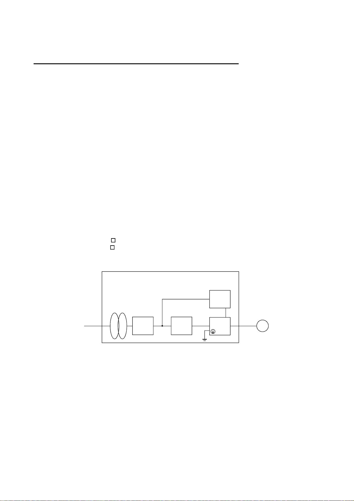
(2) Configuration
Control box
Reinforced
insulating type
Reinforced
insulating
transformer
No-fuse
breaker
NFB
Magnetic
contactor
MC
24VDC
power
supply
Servo
amplifier
Servo
motor
SM
Use the no-fuse breaker and magnetic contactor which conform to the EN or IEC Standard.
Design notice: Where residual-current-operated protective device (RCD) is used for protection case of
direvt or indirect contact, only RCD of type B is allowed on the supply side of this Electronic
Equipment(EE).
(3) Environment
Operate the servo amplifier at or above the contamination level 2 set forth in IEC664. For this
purpose, install the servo amplifier in a control box which is protected against water, oil, carbon, dust,
dirt, etc. (IP54).
(4) Power supply
(a) Operate the servo amplifier to meet the requirements of the overvoltage category II set forth in
IEC664. For this purpose, a reinforced insulating transformer conforming to the IEC or EN
Standard should be used in the power input section.
(b) As the external power supply for interface, use a 24VDC power supply that has been insulation-
reinforced in I/O.
A - 7
Page 9
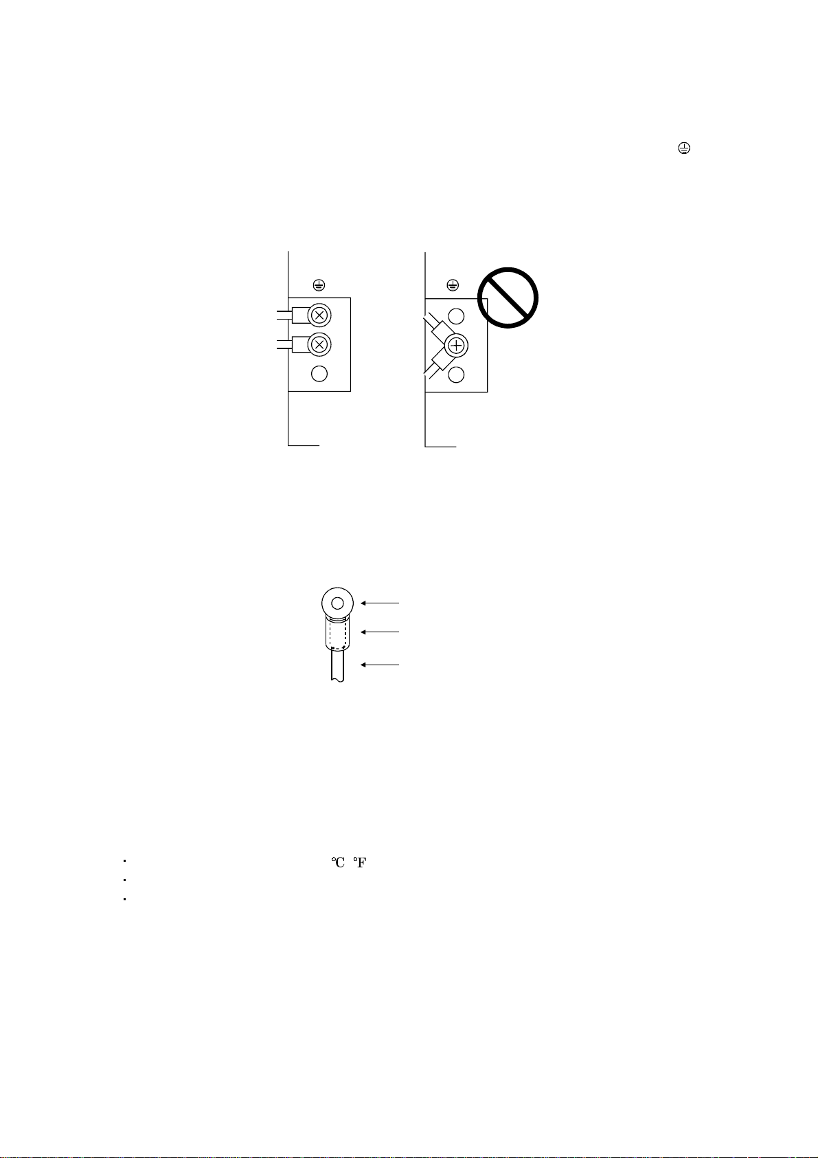
(5) Grounding
(a) To prevent an electric shock, always connect the protective earth (PE) terminals (marked
servo amplifier to the protective earth (PE) of the control box. Connect PE terminal of the control
box to the NEUTRAL of a power supply. Be sure to ground the NEUTRAL of a power supply.
(b) Do not co nnect two g round c ables to the same pro tective e arth (PE) terminal. Always c onnect the
cables to the terminals one-to-one.
PE terminals PE terminals
(c) If a leakage current breaker is used to prevent an electric shock, the protective earth (PE) terminals
of the servo amplifier must be c onne ct ed t o t h e c orr es pondi n g eart h te rmi nal s.
) of the
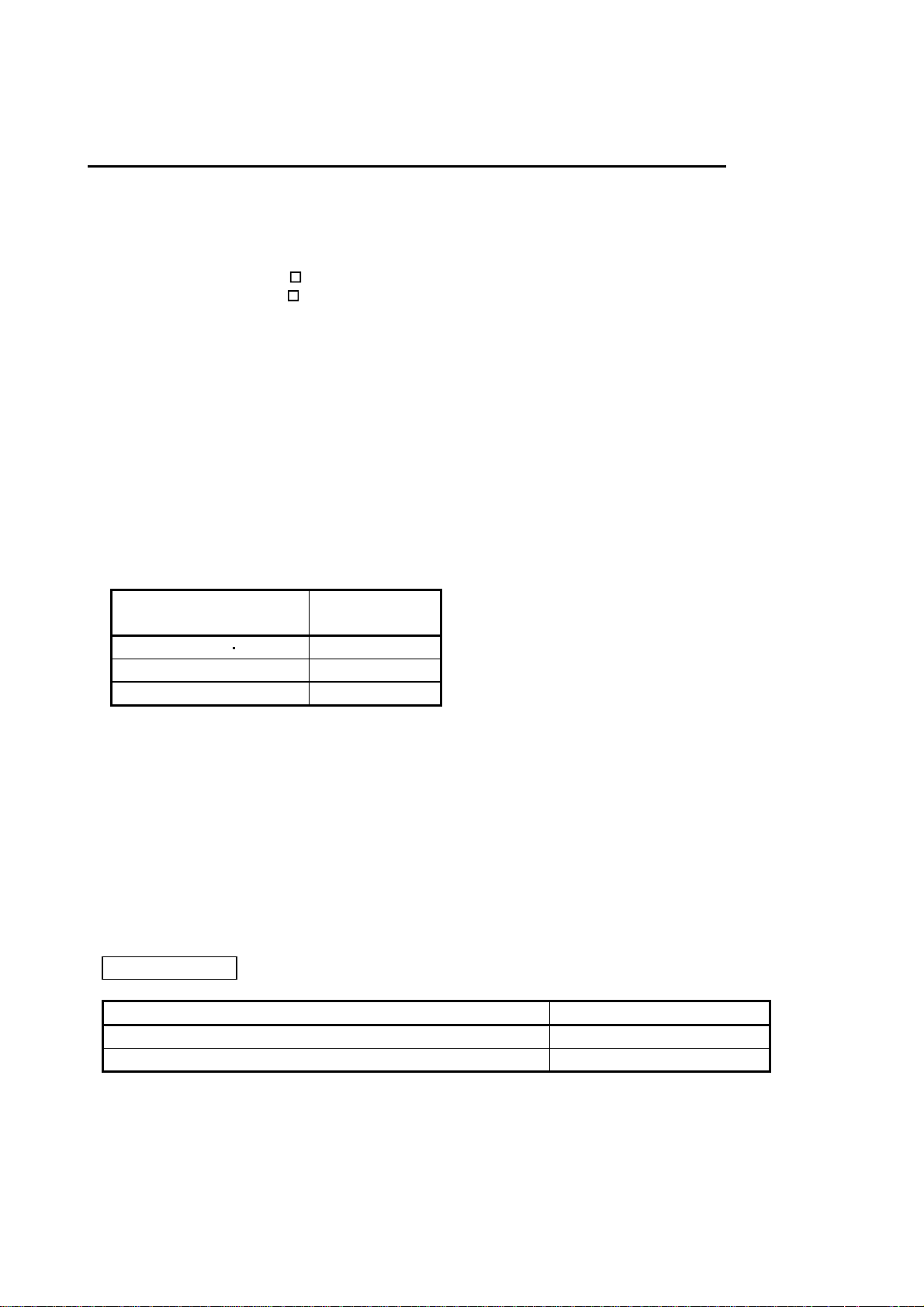
(6) Wiring
(a) The cables to be connected to the terminal block of the servo amplifier must have crimping
terminals provided with insulating tubes to prevent contact with adjacent terminals.
Crimping terminal
Insulating tube
Cable
(b) Use the servo motor side power connector which complies with the EN Standard. The EN
Standard-compliant power connector sets are available from us as options. (Refer to Section 13 .1.2)
(7) Auxiliary equipment and options
(a) The no-fuse breaker and magnetic contactor used should be the EN or IEC standard-compliant
products of the models described in Section 13.2.2.
(b) The sizes of the cable s described in Section 13.2. 1 meet the following req uirements. To meet t he
other requirements, follow Table 5 and Appendix C in EN60204-1.
Ambient tempera t ur e: 40 (104 ) [ ( )]
Sheath: PVC (polyvinyl chloride)
Installed on wall surface or open table tray
(c) Use the EMC filter for noise reduction.
(8) Performing EMC tests
When EMC tests are ru n on a machine/device into which the servo amplifier has been installed, it
must conform to the electromagnetic compatibility (immunity/emission) standards after it has
satisfied the operating environment/electrical equipment specificati ons.
For the other EMC directive guidelines on the servo amplifier, refer to the EMC Installation
Guidelines(IB(NA)67310).
A - 8
Page 10
CONFORMANCE WITH UL/C-UL STANDARD
(1) Servo amplifiers and servo motors used (Acquisition schedule)
Use the servo amplifiers and servo motors which comply with the standard model.
Servo amplifier :MR-E-10A to MR-E-200A
Servo motor :HC-KFE
HC-SFE
(2) Installation
3
Install a fan of 100CFM (2.8 m
cooling of at least equivalent capability.
(3) Short circuit rating
This servo amplifier conforms to the circuit whose peak current is limited to 5000A or less. Having
been subjected to the short-circuit tests of the UL in the alternating-current circuit, the servo
amplifier conforms to the above circuit.
(4) Capacitor discharge time
The capacitor disc har ge tim e is a s listed belo w. To ensu re safety , do no t touch th e ch arg ing sec tion for
10 minutes after power-off.
/min) air flow 4 in (10.16 cm) above the servo amplifier or provide
Servo amplifier
MR-E-10A 20A 1
MR-E-40A 2
MR-E-70A to 200A 3
(5) Options and auxiliary equipment
Use UL/C-UL standard-compliant products.
(6) About wiring protection
For installation in United States , branch circuit protecti on must be provided, in accordance with the
National Electrical Code and any applicable local codes.
For installation in Canada, branch circuit protection must be provided, in accordance with the Canada
Electrical Code and any applicable provincial codes.
<<About the manual s>>
Relevant manuals
MR-E Series To Use the AC Servo Safely IB(NA)0300057
EMC Installation Guidelines IB(NA)67310
Discharge time
[min]
Manual name Manual No.
A - 9
Page 11

MEMO
A - 10
Page 12

CONTENTS
1. FUNCTIONS AND CONFIGURATION 1- 1 to 1-10
1.1 Introduction.............................................................................................................................................. 1- 1
1.2 Function block diagram ..........................................................................................................................1- 2
1.3 Servo amplifier standard specifications................................................................................................1- 3
1.4 Function list.............................................................................................................. ...............................1- 4
1.5 Model code definition ..............................................................................................................................1- 6
1.6 Combination with servo motor............................................................................................... ................1- 6
1.7 Parts identification..................................................................................................................................1- 7
1.8 Servo system with auxiliary equipment................................................................................................1- 9
2. INSTALLATION 2- 1 to 2- 4
2.1 Environmental conditions.......................................................................................................................2- 1
2.2 Installation direction and clearances ....................................................................................................2- 2
2.3 Keep out foreign materials .....................................................................................................................2- 3
2.4 Cable stress..............................................................................................................................................2- 3
3. SIGNALS AND WIRING 3- 1 to 3- 48
3.1 Standard connection example ................................................................................................................3- 2
3.1.1 Position control mode .......................................................................................................................3- 2
3.1.2 Internal speed control mode ............................................................................................................3- 8
3.2 Internal connection diagram of servo amplifier ...................................................................................3- 9
3.3 I/O signals................................................................................................................................................3-10
3.3.1 Connectors and signal arrangements............................................................................................3-10
3.3.2 Signal explanations .........................................................................................................................3-13
3.4 Detailed description of the signals........................................................................................................3-19
3.4.1 Position control mode ......................................................................................................................3-19
3.4.2 Internal speed control mode ...........................................................................................................3-24
3.4.3 Position/internal speed control change mode................................................................................3-26
3.5 Alarm occurrence timing chart .............................................................................................................3-28
3.6 Interfaces.................................................................................................................................................3-29
3.6.1 Common line ....................................................................................................................................3-29
3.6.2 Detailed description of the interfaces............................................................................................3-30
3.7 Input power supply circuit.....................................................................................................................3-34
3.7.1 Connection example.........................................................................................................................3-34
3.7.2 Terminals..........................................................................................................................................3-35
3.7.3 Power-on sequence...........................................................................................................................3-36
3.8 Connection of servo amplifier and servo motor...................................................................................3-37
3.8.1 Connection instructions ..................................................................................................................3-37
3.8.2 Connection diagram.........................................................................................................................3-37
3.8.3 I/O terminals....................................................................................................................................3-39
3.9 Servo motor with electromagnetic brake .............................................................................................3-41
3.10 Grounding .............................................................................................................................................3-44
3.11 Servo amplifier connectors (CNP1, CNP2) wiring method
(When MR-ECPN1-B and MR-ECPN2-B of an option are used.)...................................................3-45
3.12 Instructions for the 3M connector.......................................................................................................3-48
1
Page 13

4. OPERATION 4- 1 to 4- 6
4.1 When switching power on for the first time..........................................................................................4- 1
4.2 Startup......................................................................................................................................................4- 2
4.2.1 Selection of control mode..................................................................................................................4- 2
4.2.2 Position control mode .......................................................................................................................4- 2
4.2.3 Internal speed control mode ............................................................................................................4- 4
5. PARAMETERS 5- 1 to 5- 30
5.1 Parameter list..........................................................................................................................................5- 1
5.1.1 Parameter write inhibit ...................................................................................................................5- 1
5.1.2 Lists....................................................................................................................................................5- 2
5.2 Detailed description ...............................................................................................................................5-25
5.2.1 Electronic gear .................................................................................................................................5-25
5.2.2 Analog monitor.................................................................................................................................5-26
5.2.3 Using forward/reverse rotation stroke end to change the stopping pattern..............................5-29
5.2.4 Alarm history clear..........................................................................................................................5-29
5.2.5 Position smoothing ..........................................................................................................................5-30
6. DISPLAY AND OPERATION 6- 1 to 6-14
6.1 Display flowchart..................................................................................................................................... 6- 1
6.2 Status display ..........................................................................................................................................6- 2
6.2.1 Display examples.............................................................................................................................. 6- 2
6.2.2 Status display list.............................................................................................................................6- 3
6.2.3 Changing the status display screen................................................................................................6- 4
6.3 Diagnostic mode.......................................................................................................................................6- 5
6.4 Alarm mode..............................................................................................................................................6- 6
6.5 Parameter mode ......................................................................................................................................6- 7
6.6 External I/O signal display.....................................................................................................................6- 8
6.7 Output signal (DO) forced output .........................................................................................................6-10
6.8 Test operation mode...............................................................................................................................6-11
6.8.1 Mode change.....................................................................................................................................6-11
6.8.2 Jog operation....................................................................................................................................6-12
6.8.3 Positioning operation.......................................................................................................................6-13
6.8.4 Motor-less operation........................................................................................................................6-14
7. GENERAL GAIN ADJUSTMENT 7- 1 to 7-10
7.1 Different adjustment methods ...............................................................................................................7- 1
7.1.1 Adjustment on a single servo amplifier..........................................................................................7- 1
7.1.2 Adjustment using servo configuration software............................................................................7- 2
7.2 Auto tuning ..............................................................................................................................................7- 3
7.2.1 Auto tuning mode .............................................................................................................................7- 3
7.2.2 Auto tuning mode operation............................................................................................................7- 4
7.2.3 Adjustment procedure by auto tuning............................................................................................7- 5
7.2.4 Response level setting in auto tuning mode...................................................................................7- 6
2
Page 14

7.3 Manual mode 1 (simple manual adjustment).......................................................................................7- 7
7.3.1 Operation of manual mode 1 ...........................................................................................................7- 7
7.3.2 Adjustment by manual mode 1 .......................................................................................................7- 7
7.4 Interpolation mode .................................................................................................................................7-10
8. SPECIAL ADJUSTMENT FUNCTIONS 8- 1 to 8-10
8.1 Function block diagram ..........................................................................................................................8- 1
8.2 Machine resonance suppression filter ...................................................................................................8- 1
8.3 Adaptive vibration suppression control.................................................................................................8- 3
8.4 Low-pass filter .........................................................................................................................................8- 4
8.5 Gain changing function...........................................................................................................................8- 5
8.5.1 Applications....................................................................................................................................... 8- 5
8.5.2 Function block diagram....................................................................................................................8- 5
8.5.3 Parameters........................................................................................................................................8- 6
8.5.4 Gain changing operation..................................................................................................................8- 8
9. INSPECTION 9- 1 to 9- 2
10. TROUBLESHOOTING 10- 1 to 10-12
10.1 Trouble at start-up ..............................................................................................................................10- 1
10.1.1 Position control mode...................................................................................................................10- 1
10.1.2 Internal speed control mode ........................................................................................................10- 4
10.2 When alarm or warning has occurred...............................................................................................10- 5
10.2.1 Alarms and warning list ..............................................................................................................10- 5
10.2.2 Remedies for alarms.....................................................................................................................10- 6
10.2.3 Remedies for warnings................................................................................................................10-11
11. OUTLINE DIMENSION DRAWINGS 11- 1 to 11- 8
11.1 Servo amplifiers...................................................................................................................................11- 1
11.2 Connectors............................................................................................................................................11- 5
12. CHARACTERISTICS 12- 1 to 12- 4
12.1 Overload protection characteristics...................................................................................................12- 1
12.2 Power supply equipment capacity and generated loss ....................................................................12- 1
12.3 Dynamic brake characteristics...........................................................................................................12- 3
12.4 Encoder cable flexing life....................................................................................................................12- 4
13. OPTIONS AND AUXILIARY EQUIPMENT 13- 1 to 13-32
13.1 Options..................................................................................................................................................13- 1
13.1.1 Regenerative brake options.........................................................................................................13- 1
13.1.2 Cables and connectors..................................................................................................................13- 6
13.1.3 Analog monitor, RS-232C branch cable (MR-E3CBL15-P).....................................................13-19
13.1.4 Servo configurations software....................................................................................................13-20
3
Page 15

13.2 Auxiliary equipment ..........................................................................................................................13-21
13.2.1 Recommended wires....................................................................................................................13-21
13.2.2 No-fuse breakers, fuses, magnetic contactors...........................................................................13-23
13.2.3 Power factor improving reactors................................................................................................13-23
13.2.4 Relays............................................................................................................................................13-24
13.2.5 Surge absorbers ...........................................................................................................................13-24
13.2.6 Noise reduction techniques.........................................................................................................13-24
13.2.7 Leakage current breaker.............................................................................................................13-30
13.2.8 EMC filter.....................................................................................................................................13-32
14. SERVO MOTOR 14- 1 to 14- 38
14.1 Compliance with the overseas standards..........................................................................................14- 1
14.1.1 Compliance with EC directives...................................................................................................14- 1
14.1.2 Conformance with UL/C-UL standard.......................................................................................14- 1
14.2 Model name make-up..........................................................................................................................14- 2
14.3 Parts identification..............................................................................................................................14- 4
14.4 Installation...........................................................................................................................................14- 5
14.4.1 Environmental conditions............................................................................................................14- 6
14.4.2 Installation orientation................................................................................................................14- 6
14.4.3 Load mounting precautions.........................................................................................................14- 7
14.4.4 Permissible load for the shaft......................................................................................................14- 8
14.4.5 Protection from oil and water.....................................................................................................14-11
14.4.6 Cable .............................................................................................................................................14-12
14.5 Connectors used for servo motor wiring...........................................................................................14-13
14.5.1 HC-KFE series.............................................................................................................................14-13
14.5.2 HC-SFE series..............................................................................................................................14-13
14.6 Specifications......................................................................................................................................14-19
14.6.1 Standard specifications...............................................................................................................14-19
14.6.2 Torque characteristics.................................................................................................................14-21
14.6.3 Servo motors with reduction gears............................................................................................14-22
14.6.4 Servo motors with special shafts................................................................................................14-25
14.6.5 D cut..............................................................................................................................................14-25
14.7 Characteristics....................................................................................................................................14-26
14.7.1 Electromagnetic brake characteristics......................................................................................14-26
14.7.2 Vibration rank..............................................................................................................................14-28
14.7.3 Machine Accuracies.....................................................................................................................14-28
14.8 Outline dimension drawing...............................................................................................................14-29
14.8.1 HC-KFE series.............................................................................................................................14-29
14.8.2 HC-SFE series..............................................................................................................................14-32
14.9 Outline dimension drawing (in inches) ............................................................................................14-34
14.9.1 HC-KFE series.............................................................................................................................14-34
14.9.2 HC-SFE series..............................................................................................................................14-37
4
Page 16

15. MR-E-
15.1. Functions and configuration..............................................................................................................15- 1
15.1.1 Introduction...................................................................................................................................15- 1
15.1.2 Function block diagram ...............................................................................................................15- 2
15.1.3 Servo amplifier standard specifications.....................................................................................15- 3
15.1.4 Model code definition....................................................................................................................15- 4
15.1.5 Parts identification.......................................................................................................................15- 4
15.1.6 Servo system with auxiliary equipment.....................................................................................15- 6
15.2. Signals and wiring..............................................................................................................................15- 8
15.2.1 Standard connection example .....................................................................................................15- 8
15.2.2 Internal connection diagram of servo amplifier .......................................................................15-11
15.2.3 Connectors and signal arrangements........................................................................................15-12
15.2.4 Signal explanations.....................................................................................................................15-14
15.2.5 Detailed description of the signals.............................................................................................15-18
15.3 Startup.................................................................................................................................................15-25
15.3.1 Speed control mode......................................................................................................................15-25
15.3.2 Torque control mode....................................................................................................................15-27
15.4 Parameters..........................................................................................................................................15-29
15.4.1 Item list.........................................................................................................................................15-29
15.4.2 Details list ....................................................................................................................................15-32
15.5 Display and operation........................................................................................................................15-51
15.5.1 Display flowchart.........................................................................................................................15-51
15.5.2 Status display...............................................................................................................................15-53
15.5.3 Diagnostic mode...........................................................................................................................15-55
15.5.4 External I/O signal display.........................................................................................................15-57
15.6. Troubleshooting.................................................................................................................................15-59
15.6.1 Trouble at start-up ......................................................................................................................15-59
15.6.2 Alarms and warning list .............................................................................................................15-61
AG SERVO AMPLIFIER COMPATIBLE WITH ANALOG INPUT 15- 1 to 15- 62
5
Page 17

MEMO
6
Page 18

1. FUNCTIONS AND CONFIGURATION
1. FUNCTIONS AND CONFIGURATION
1.1 Introduction
The Mitsubishi MR-E series general-purpose AC servo is based on the MR-J2-Super series, and has the
same high performance and limited functions.
It has position control and internal speed control modes. Further, it can perform operation with the
control modes changed, e.g. position/internal speed control. Hence, it is applicable to a wide range of
fields, precision positioning and smooth speed control of machine tools and general industrial machines.
As this new series has the RS-232C or RS-422 serial communication function, a servo configuration
software-installed personal computer or the like can be used to perform parameter setting, test operation,
status display monitoring, gain adjustment, etc.
With real-time auto tuning, you can automatically adjust the servo gains according to the machine.
The MR-E series servo motor is equipped with an incremental position encoder that has the resolution of
10000 pulses/rev to ensure high precision positioning.
(1) Position control mode
An up to 500kpps high-speed pulse train is used to control the speed and direction of a motor and
execute precision positioning of 10000 pulses/rev resolution.
The position smoothing function provides a choice of two different modes appropriate for a machine, so
a smoother start/stop can be made in response to a sudden position command.
A torque lim it is imposed on th e se rv o amp l if ier by the clamp circuit to p ro te c t the powe r transisto r in
the main circuit from overcurrent due to sudden acceleration/deceleration or overload. This torque
limit value can be changed to any value with the parameter.
(2) Internal spee d co nt rol mode
The parameter-driven internal speed command (max. 7 speeds) is used to control the speed and
direction of a servo motor smoothly.
There are also the acceleration/deceleration time constant setting in response to speed command, the
servo lock function at a stop time.
1 - 1
Page 19
1. FUNCTIONS AND CONFIGURATION
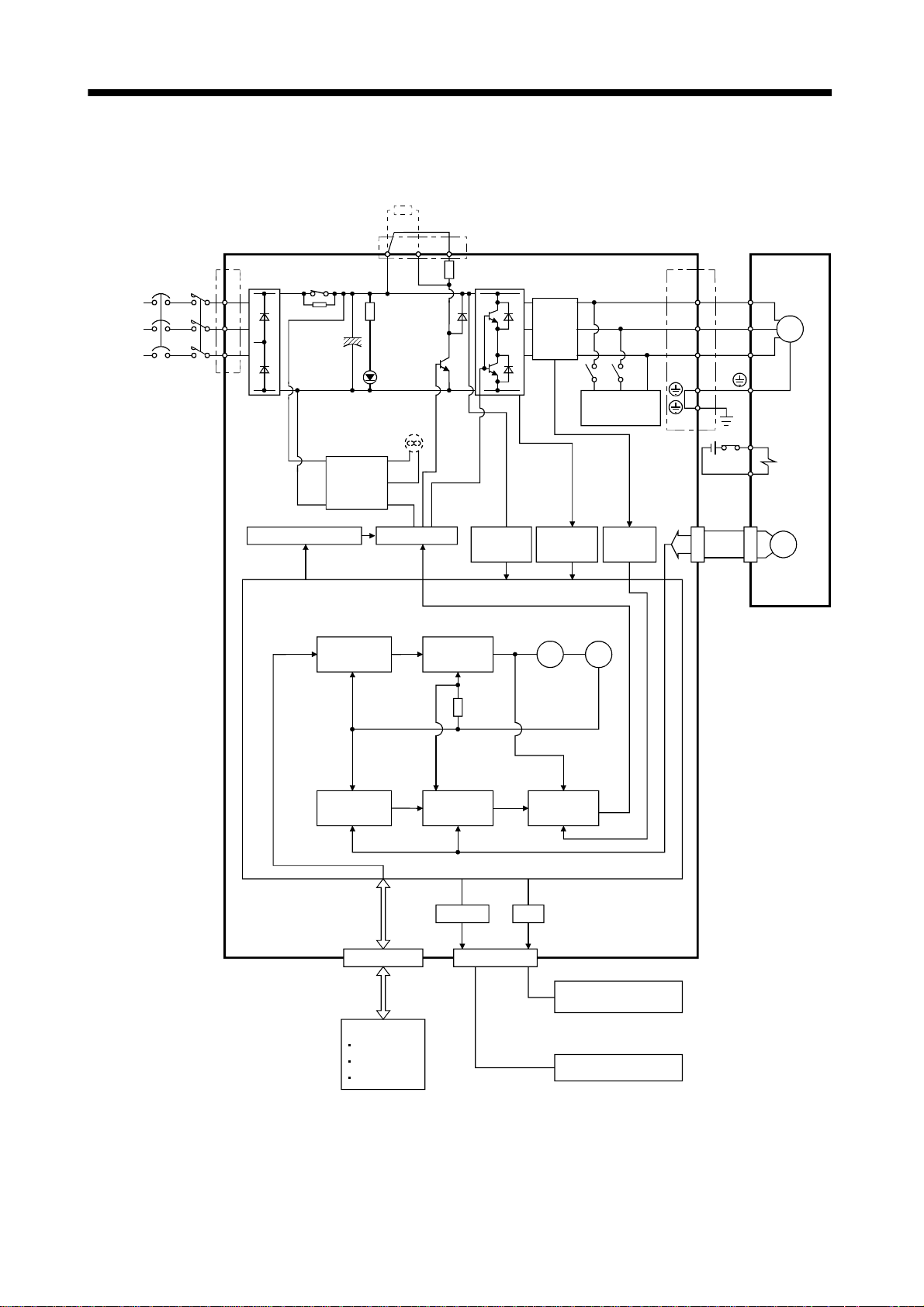
1.2 Function block diagram
The function block diagram of this servo is shown below.
Regenerative brake option
(Note 3)
(Note 2)
Power
supply
3-phase
200 to
230VAC,
1-phase
230VAC
(Note 3)
NFB MC
Servo amplifier
1
L
2
L
3
L
Regene rative br ake
RADS
Regenerative
TR
CHARGE
Fan
(MR-E-200A only)
Control
power
supply
Base amplifier
P
lamp
D
C
(Note 1)
Voltage
detection
Current
detector
Overcurrent
protection
Dynamic
brake
Current
detection
(Note 3)
U
V
W
(Note 3)
CN2
Servo motor
U
V
W
E1
E2
Encoder
SM
Electromagnetic
brake
Pulse
input
Model position
control
Model speed
control
Virtual
encoder
Virtual
motor
Model
position
Actual position
control
Model
speed
Actual speed
control
Model torque
Current
control
RS-232C D/A
I/F
CN1
(Note 3)(Note 3)
CN3
Analog monitor
(2 channels)
D I/O control
Servo on
Start
Failure, etc.
Controller
RS-232C
Note:1. The built-in regenerative brake resistor is not provided for the MR-E-10A/20A.
2. The single-phase 230VAC can be used for MR-E-70A or smaller servo amplifier.
1
Connect the power supply cables to L
and L2 while leaving L3 open.
3. The control circuit connectors (CN1, CN2 and CN3) are safely isolated from main circuit terminals
1
(L
, L2, L3, U, V, W, P, C and D).
1 - 2
Page 20
1. FUNCTIONS AND CONFIGURATION
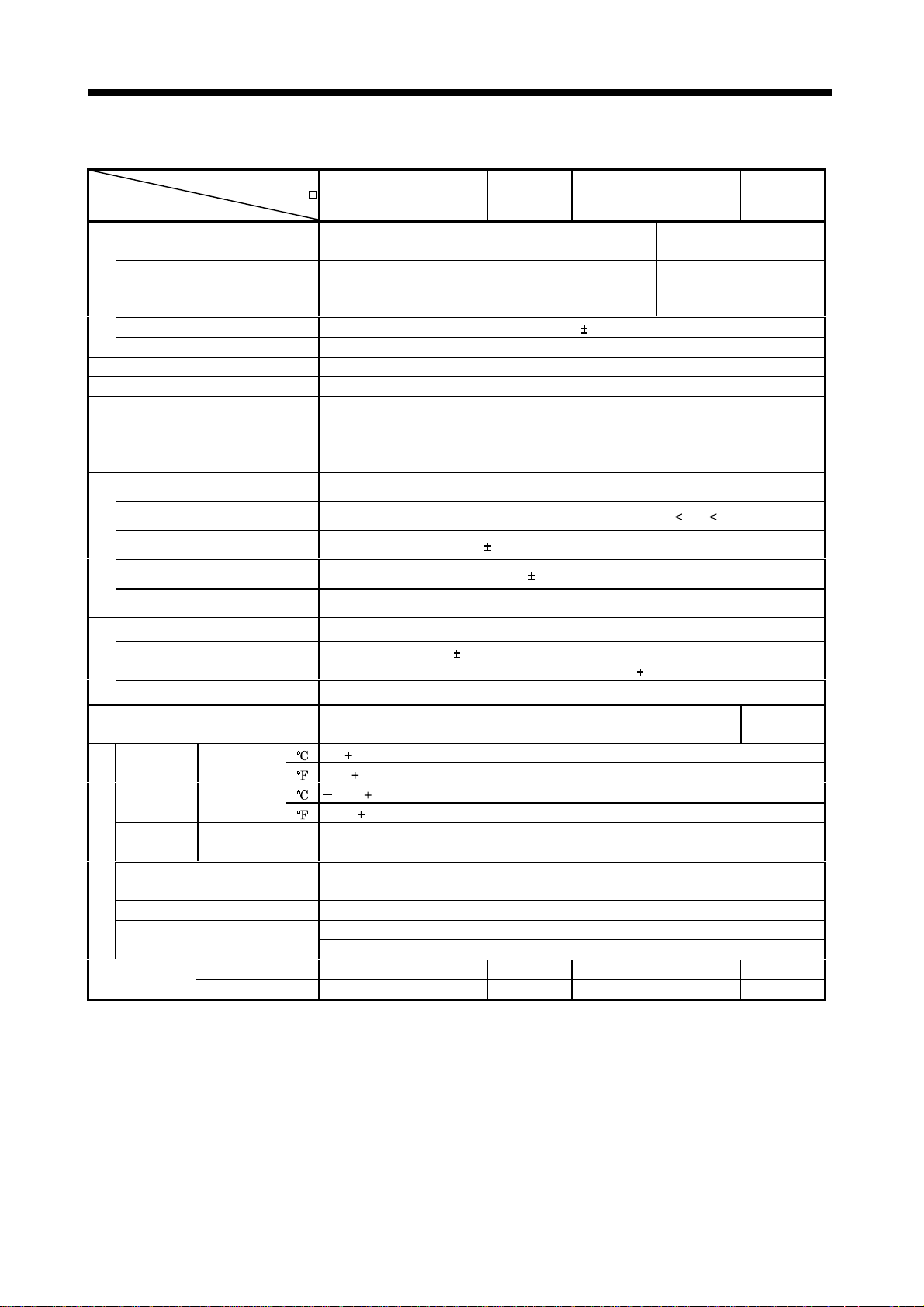
1.3 Servo amplifier standard specifications
Servo Amplifier
MR-E-
Item
Voltage/frequency
Permissible voltage fluctuation
Power supply
Permissible frequency fluctuation Within 5%
Power supply capacity Refer to Section12.2
System Sine-wave PWM control, curr ent control system
Dynamic brake Built-in
Protective functions
Max. input pulse frequency 500kpps (for differential receiver), 200kpps (for open collector)
Command pulse multiplying factor Electronic gear A:1 to 65535 B:1 to 65535, 1/50 A/B 50
10A 20A 40A 70A 100A 200A
3-phase 200 to 230VAC, 50/60Hz or 1-phase 230VAC,
50/60Hz
3-phase 200 to 230VAC:
170 to 253VAC
1-phase 230VAC: 207 to 253VAC
Overcurrent shut-off, regenerative overvoltage shut-off, overload shut-off (electronic
thermal relay), encoder error protection, regenerative brake error protection,
undervoltage, instantaneous power failure protection, overspeed protection, excessive
error protection
3-phase 200 to 230VAC,
50/60Hz
3-phase 170 to 253VAC
In-position range setting 0 to 10000 pulse (command pulse unit)
Error excessive 10 revolutions
Position control mode
Torque limit Set by pa rameter setting
Speed control range Internal speed command 1: 5000
Speed fluctuation ratio
control mode
Torque limit Set by pa rameter setting
Internal speed
Structure Self-cooled, open (I P00 )
Ambient
temperature
Ambient
humidity
Ambient
Environment
Altitude Max. 1000m (3280ft) above sea level
Vibration
Weight
Operation
Storage
Operation
Storage
[ ]0 to 55 (non-freezing)
[
] 32 to 131 (non-freezing)
[ ] 20 to 65 (non-freezing)
[
] 4 to 149 (non-freezing)
90%RH or less ( non - condensing)
Indoors (no dir ect su nl i gh t )
Free from corrosive gas, flammable gas, oil mist, dust and dirt
5.9 [m/s2] or less
19.4 [ft/s
[kg] 0.8 0.8 1.2 1.8 1.8 2.0
[lb] 1.8 1.8 2.6 4.0 4.0 4.4
2
] or less
0.01% or less (load fluctuation 0 to 100%)
0% or less (power fluctuation
10%)
Force-cooling,
open (IP00)
1 - 3
Page 21
1. FUNCTIONS AND CONFIGURATION
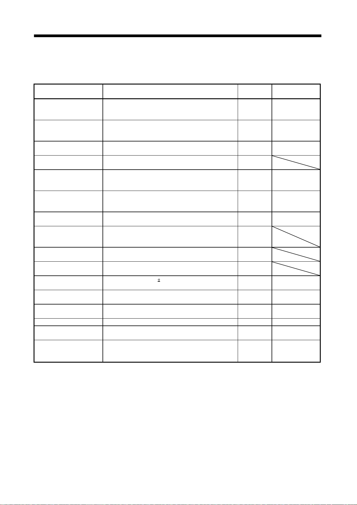
1.4 Function list
The following table lists the functions of this servo. For details of the functions, refer to the corresponding
chapters and sections.
Function Description
Position control mode This servo is used as position control servo. P
Internal speed control mod e This servo is used as internal spe ed cont rol servo. S
Position/internal speed
control change mode
High-resolut ion encoder
Gain changing function
Adaptive vibration
suppression control
Low-pass filter
Machine analyzer function
Machine simulation
Gain search function
Slight vibration suppression
control
Electronic gear Input pulses can be multiplied by 1/50 to 50. P
Auto tuning
Position smoothing Speed can be increased smoothly in response to input pulse. P Parameter No. 7
S-pattern acceleration/
deceleration time constant
Regenerative brake option
Using external input signal, control can be switched
between position control and internal speed control.
High-resolution encoder of 131072 pulses/rev is used as a
servo motor encoder.
You can switch between gains during rotation and gains
during stop or use an external input signal to change gains
during operation.
Servo amplifier detects mechanical resonance and sets filter
characteristics automatically to suppress mechanical
vibration.
Suppresses high-frequency resonance which occurs as servo
system response is increased.
Analyzes the frequency characteristic of the mechanical
system by simply connecting a servo configuration softwareinstalled personal computer and servo amplifier.
Can simulate machine motions on a personal computer
screen on the basis of the machine analyzer results.
Personal computer changes gains automatically and
searches for overshoot-free gains in a short time.
Suppresses vibration of 1 pulse produced at a servo motor
stop.
Automatically adjusts the gain to optimum value if load
applied to the servo motor shaft varies.
Speed can be increased and decreased smoothly. S Parameter No. 13
Used when the built-in regenerative brake resistor of the
servo amplifier does not have sufficient regenerative
capability for the regenerative power generated.
(Note)
Control mode
Section 3.1.1
Section 3.4.1
Section 4.2.2
Section 3.1.2
Section 3.4.2
Section 4.2.3
P/S Section 3.4.4
P, S, T
P, S Section 8.5
P, S Section 8.3
P, S Section 8.4
P
P
P
P Parameter No. 20
Parameters No. 3, 4,
69 to 71
P, S Chapter 7
P, S Section 13.1.1
Refer to
1 - 4
Page 22

1. FUNCTIONS AND CONFIGURATION
Function Description
Alarm history cl ea r Alarm history is cl eared. P, S Parameter No. 16
Restart after instantaneous
power failure
Command pulse selection
Input signal selection
Torque limit Servo motor torque can be limited to any value. P, S
Status display
External I/O signal display
Output signal (DO)
forced output
Test operati on mode
Analog monitor output Servo status is output in terms of voltage in real time. P, S Parameter No. 17
Servo configurati on sof t wa re
Alarm code output
Note:P: Position control mode, S: Internal speed control mode
P/S: Position/internal speed control change mode
If the input power supply vol tage had reduced to cause an
alarm but has returned to normal, the servo motor can be
restarted by merely switching on the start signal.
Command pulse train form can be selected from among four
different types.
Forward rotation start, reverse rotation start, servo-on and
other input signals can be assigned to any pins.
Servo status is shown on the 5-digit, 7-segment LED
display
ON/OFF statuses of external I/O signals are shown on the
display.
Output signal can be forced on/off independently of the
servo status.
Use this function for output signal wiring check, etc.
Servo motor can be run from the operation section of the
servo amplifier without the start signal entered.
Using a personal computer, parameter setting, test
operation, status display, etc. can be performed.
If an alarm has occurred, the corresponding alarm number
is output in 3-bit code.
(Note)
Control mode
S Parameter No. 20
P Parameter No. 21
P, S
P, S Section 6.2
P, S Section 6.6
P, S Section 6.7
P, S Section 6.8
P, S Section 13.1.8
P, S Section 10.2.1
Refer to
Parameters
No. 43 to 48
Section 3.4.1 (5)
Parameter No. 28
1 - 5
Page 23
1. FUNCTIONS AND CONFIGURATION
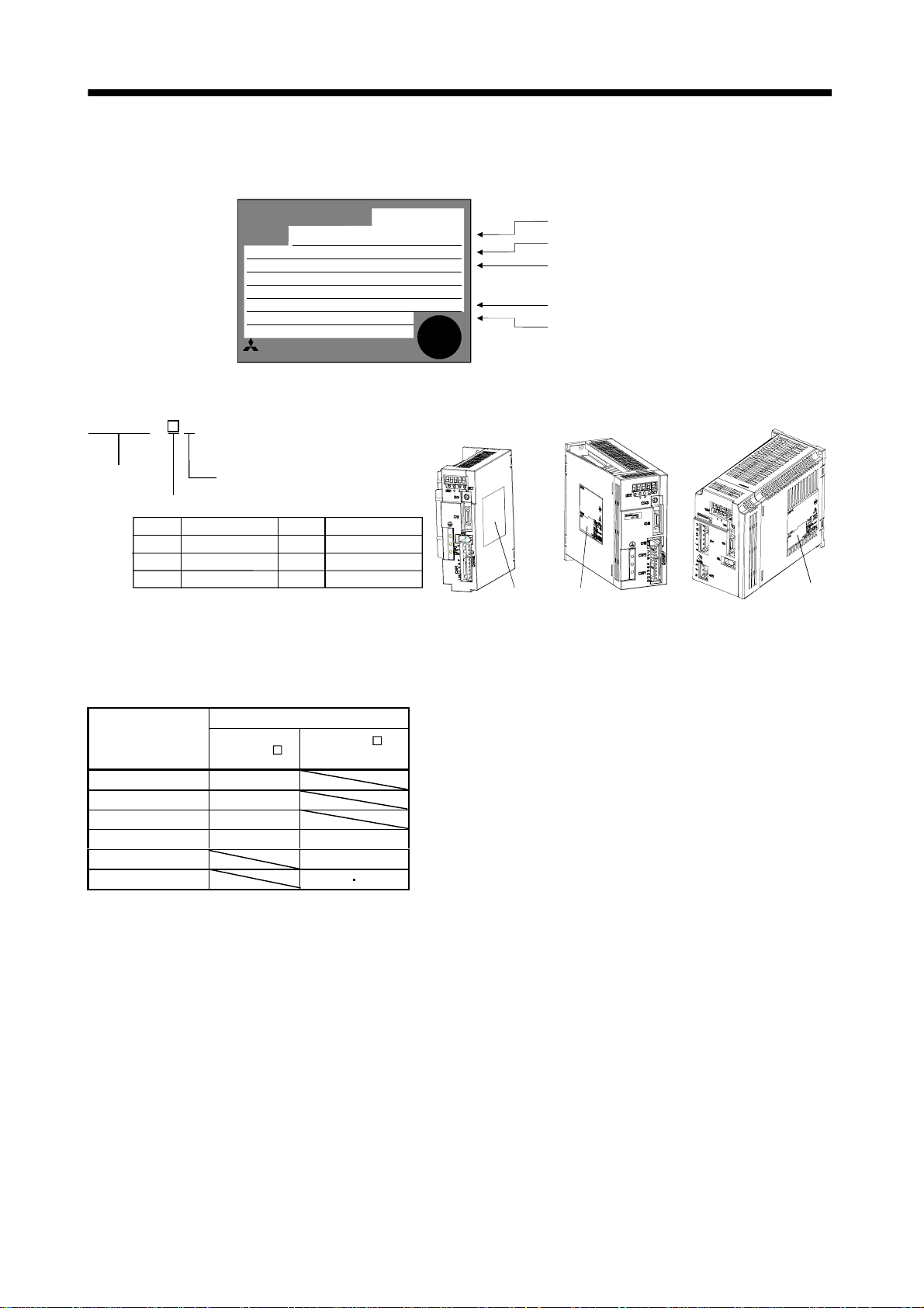
1.5 Model code definition (1) Rating plate
MITSUBISHI
MODEL
POWER
INPUT
OUTPUT
SERIAL
(2) Model
- AMR - E
Series
Rated output
Symbol
10
20
40 40 0
General-purpose interface
Rated output [W]
100
200
1.6 Combination with servo motor
MR-E-40A
:400W
:2.6A 3PH200-230V 50Hz
:2.6A3PH200-230V 60Hz
:
:170V 0-360Hz 2.8A
:XXXXYYYYY
:TCXXXAYYYGZZ
MITSUBISHI ELECTRIC CORPORATION
MADE IN JAPAN
Symbol
70
100
200 2000
Rated output [W]
750
1000
AC SERVO
AC SERVO
PASSED
Model
Capacity
Applicable power supply
Rated output current
Serial number
Rating plate Rating plate
MR-E-200AMR-E-40A or less M R-E-70A, 100A
Rating plate
The following table li sts comb ina tio n s of se rvo ampl if iers and servo mo to rs. T he sa me comb in a t ion s ap ply
to the models with electromagnetic brakes and the models with reduction gears.
Servo motors
Servo amplifier
MR-E-10A 13
MR-E-20A 23
MR-E-40A 43
MR-E-70A 73 52
MR-E-100A 102
MR-E-200A 152 202
HC-KFE
HC-SFE
2000r/min
1 - 6
Page 24
1. FUNCTIONS AND CONFIGURATION
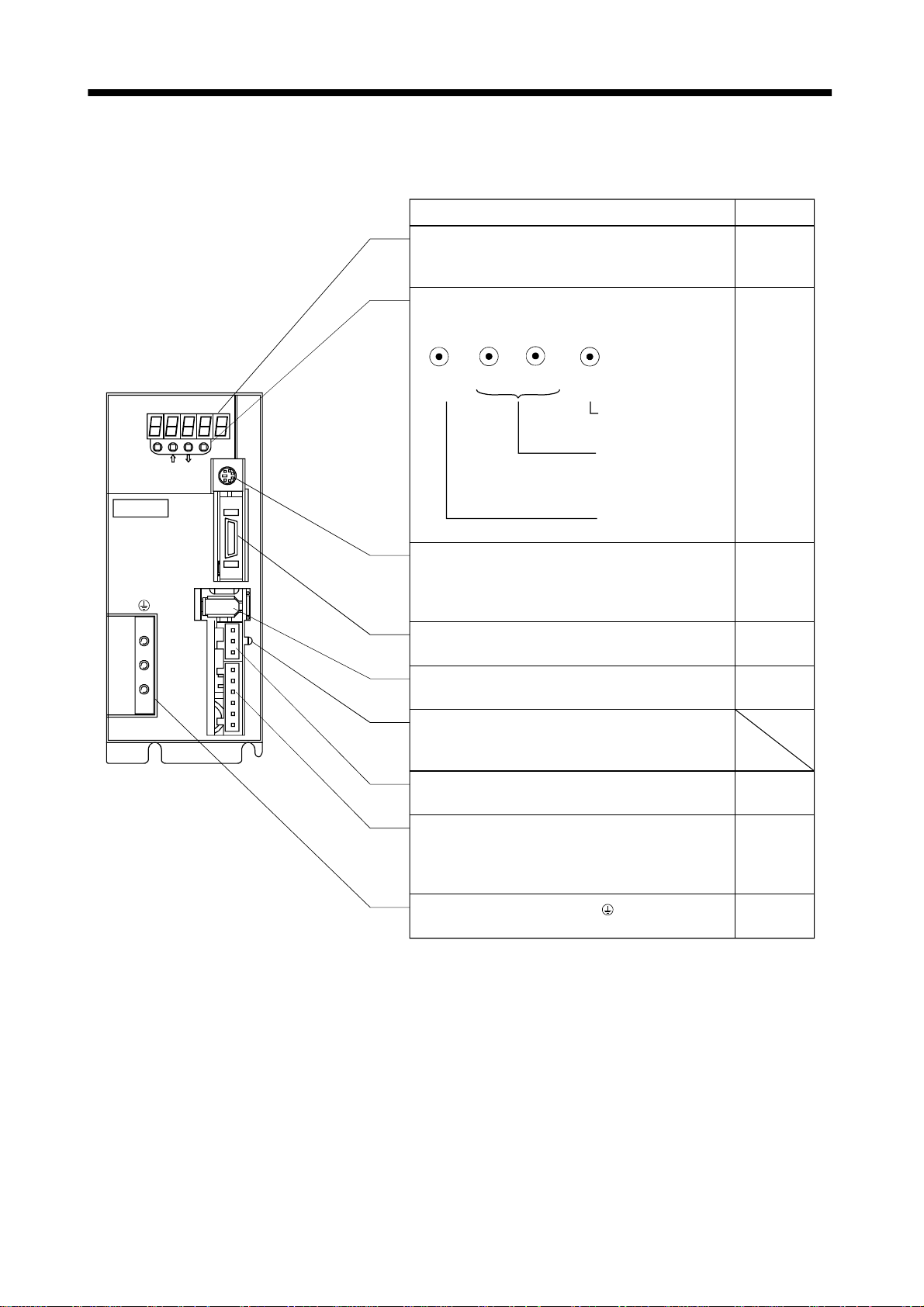
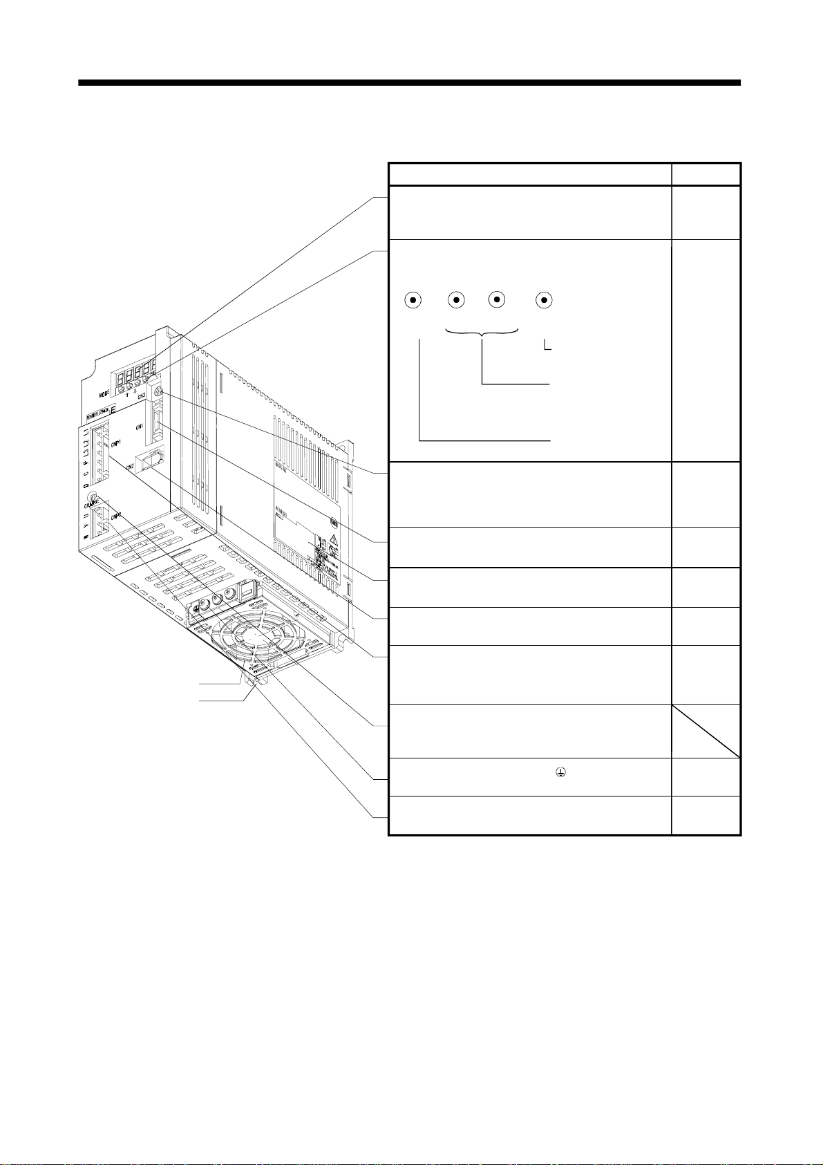
1.7 Parts identification (1) MR-E-100A or less
MODE
MITSUBISHI
MR-
CN3
CN1
CN2
CNP2
SET
Name/Application
Display
The 5-digit, seven-segment LED shows the servo
status and alarm number.
Operation section
Used to perform status display, diagnostic, alarm and
parameter setting operations.
UP
MODE
Communication connector (CN3)
Used to connect a command device (RS-232C)
and output analog monitor data.
I/O signal connector (CN1)
Used t o connect dig ital I/O signals.
DOWN
SET
Used to set data.
Used to change the
display or data in each
mode.
Used to change the
mode.
Refer to
Chapter6
Chapter6
Section3.3
Section13.1.2
Chapter14
Section3.3
CNP1
CHARGE
L3L2L1 D C P W V U
Encoder connector ( C N2 )
Connector for connection of the servo motor encoder.
Charge lamp
Lit to indicate that the main circuit is charged. While
this lamp is lit, do not reconnect the cables.
Motor power supply connector (CNP2)
Used to connect the servo mo tor.
Power supply/regenerative connector (CNP1)
Used to connect the input power supply and
regenerative brake option.
Protective earth (PE) terminal ( )
Ground terminal.
Section3.3
Section13.1.2
Section3.7
Section11.1
Section3.7
Section11.1
Section13.1.1
Section3.10
Section11.1
1 - 7
Page 25
1. FUNCTIONS AND CONFIGURATION
(2) MR-E-200A
Name/Application
Display
The 5-digit, seven-segment LED shows the servo
status and alarm number.
Operation section
Used to perform status display, diagnostic, alarm and
parameter setting operations.
DOWN
MODE
Communication connector (CN3)
Used to connect a command device (RS232C)
and output analog monitor data.
I/O signal connector (CN1)
Used to connect digital I/O signals.
UP
SET
Used to set data.
Used to change the
display or data in each
mode.
Used to change the
mode.
Refer to
Chapter6
Chapter6
Section3.3
Section13.1.2
Chapter14
Section3.3
Cooling fan
Installation notch
(4 places)
Name plate
Encoder connector (C N2)
Connector for connection of the servo motor encoder.
Power supply/regenerative connector (CNP1)
Used to connect the input power supply and
regenerative brake option.
Charge lamp
Lit to indicate that the main circuit is charged. While
this lamp is lit, do not reconnect the cables.
Protective earth (PE) terminal ( )
Ground terminal.
Motor power supply connector (CNP2)
Used to connect the servo motor.
Section1.5
Section3.3
Section13.1.2
Section3.7
Section11.1
Section13.1.1
Section3.10
Section11.1
Section3.7
Section11.1
1 - 8
Page 26
1. FUNCTIONS AND CONFIGURATION
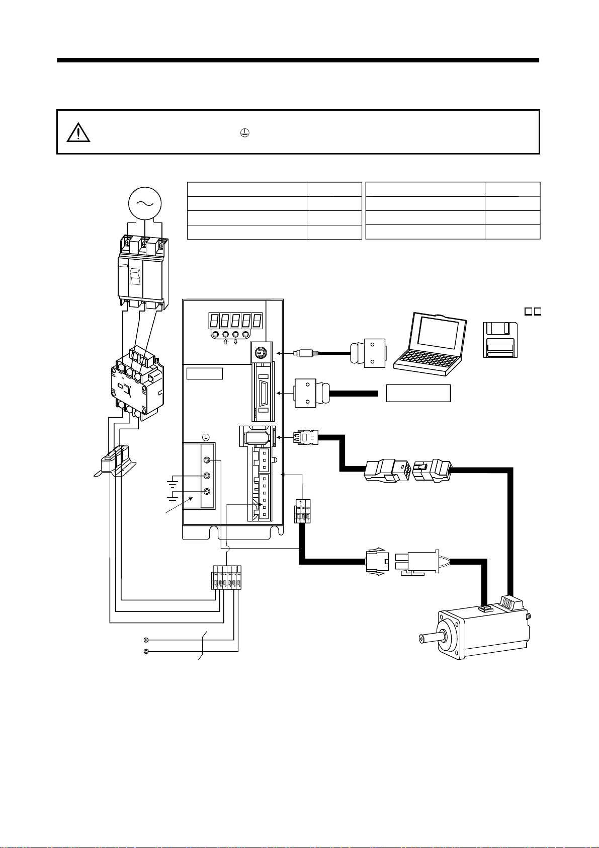
1.8 Servo system with auxiliar y equipm ent To prevent an electric shock, always connect the protective earth (PE) terminal
WARNING
(1) MR-E-100A or less
(Note 2)
3-phase 200V
to 230VAC power
supply or
1-phase 230VAC
power supply
No-fus e breaker
(NFB) or fuse
(terminal m ar ked
box.
Options and auxiliary equipment
No-fuse breaker
Magnetic contactor
Servo configuration software
) of the servo amplifier to the prot ecti ve earth (P E) of the contr ol
Refer to
Section 13.2.2
Section 13.2.2
Section 13.1.4
Options and auxiliary equipment
Regenera tive option
Cables
Power factor improving reactor
Refer to
Section 13.1.1
Section 13.2.1
Section 13.2.3
Magnetic
contactor
(MC)
Power
factor
improving
reactor
(FR-BAL)
Protective earth
(PE) terminal
Servo amplifier
MODE
MITSUBISHI
MR-E-
CN3
CN1
CN2
CNP2
CNP1
L3L2L1 D C P W V U
SET
To CN3
To CN1
To CN2
CHARGE
Personal
computer
Command device
(Note 1)
Power supply lead
Servo configuration
software
MRZJW3-SETUP1
(Note 1)
Encoder cable
3
L
2
L
1
L
P
Regenerative option
C
Servo motor
Note: 1. The HC-SFE series have cannon connectors.
2. A 1-phase 230VAC power supply may be used with the servo amplifier of MR-E-70A or less. Connect the power supply to
L
and L2 terminals and leave L3 open.
1
1 - 9
Page 27
1. FUNCTIONS AND CONFIGURATION
f
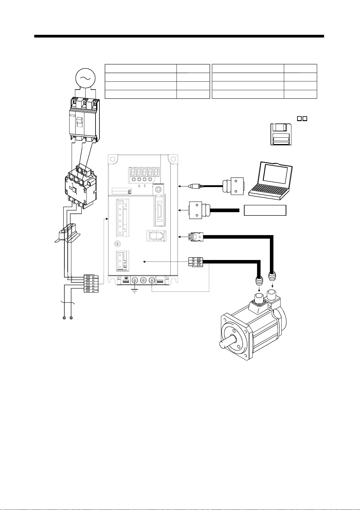
(2) MR-E-200A
3-phase 200V
to 230VAC
power supply
No-fuse
breaker
(NFB) or
fuse
Magnetic
contactor
(MC)
Power
actor
improving
reactor
(FR-BAL)
Options and auxiliary equipment
No-fuse breaker
Magnetic contactor
Servo configuration software
Servo amplifier
MODE
MITSUBIS HI
DC L3PL1L2
EZMotion
CNP1
SET
CN3
CN1
CN2
Refer to
Section 13.2.2
Section 13.2.2
Section 13.1.4
To CN3
To CN1
To CN2
Options and auxiliary equipment
Regene rative option
Refer to
Section 13.1.1
Cables Section 13.2.1
Power factor improving reactor
Section 13.2.3
Servo configuration
software
MRZJW3-SETUP1
Personal
computer
Command device
L
1
L
2
L
3
C
P
Regene rative option
CHARGE
UVW
To CNP2
CNP2
1 - 10
Page 28
2. INSTALLATION
2. INSTALLATION
CAUTION
Stacking in excess of the limited number of products is not allowed.
Install the equipment to incombustibles. Installing them directly or close to
combustibles will led to a fire.
Install the equipment in a load-bearing place in accordance with this Instruction
Manual.
Do not get on or put heavy load on the equipment to prevent injury.
Use the equipment within the specified environmental condition range.
Provide an adequate protection to prevent screws, metallic detritus and other
conductive matter or oil and other combustible matter from entering the servo
amplifier.
Do not block the intake/exhaust ports of the servo amplifier. Otherwise, a fault may
occur.
Do not subject the servo amplifier to drop impact or shock loads as they are
precision equipment.
Do not install or operate a faulty servo amplifier.
When the product has been stored for an extended period of time, consult
Mitsubishi.
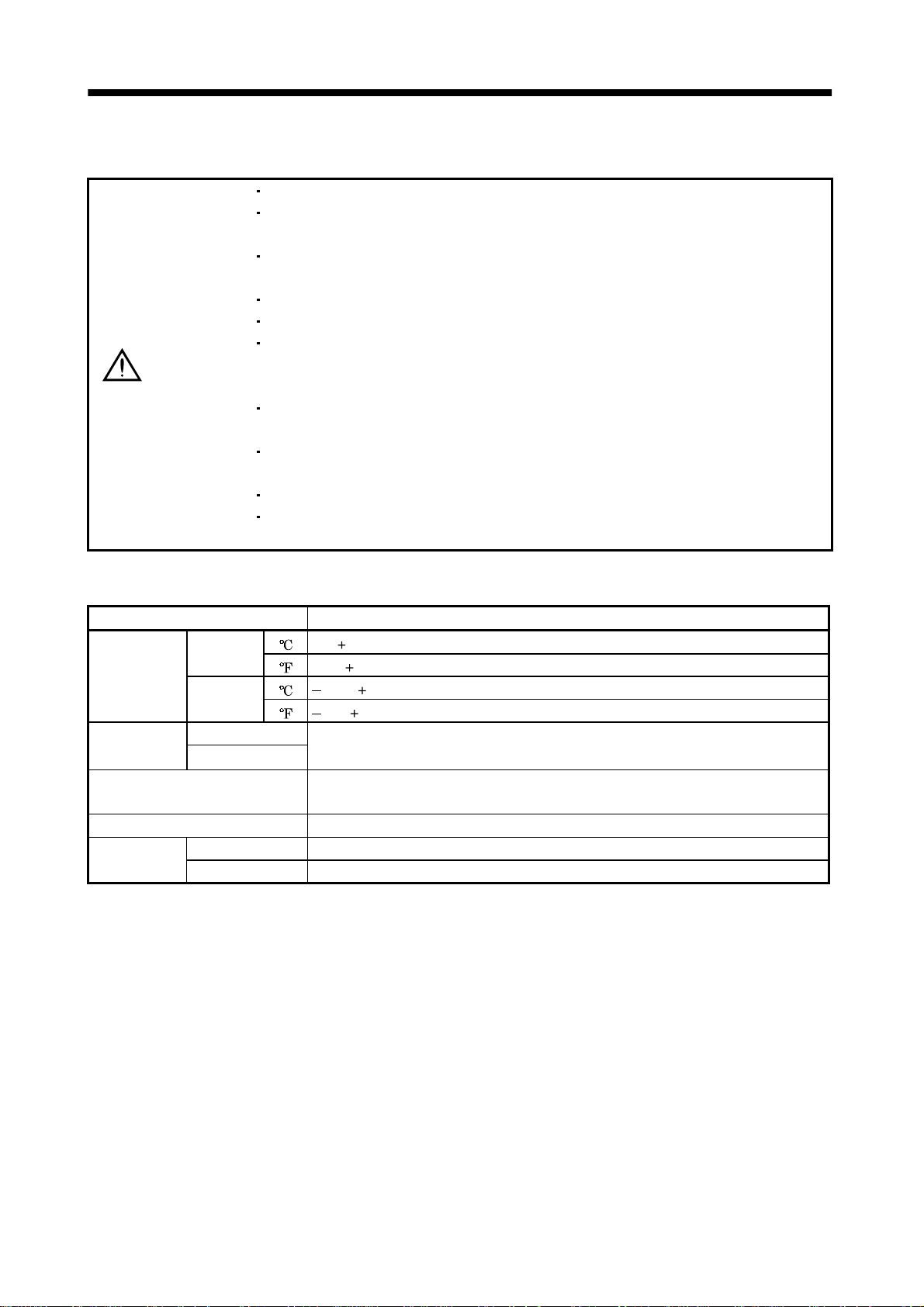
2.1 Environmental con dit ions
Environment Conditions
Ambient
temperature
Ambient
humidity
Ambience
Altitude Max. 1000m (3280 ft) above sea level
Vibration
Operation
Storage
Operation
Storage
[ ]0 to 55 (non-freezing)
[
] 32 to 131 (non-freezing)
[ ] 20 to 65 (non-freezing)
] 4 to 149 (non-freezing)
[
90%RH or less (non-condensing)
Indoors (no direct sunlight)
Free from corrosive gas, flammable gas, oil mist, dust and dirt
[m/s2] 5.9 [m/s2] or less
2
] 19.4 [ft/s2] or less
[ft/s
2 - 1
Page 29
2. INSTALLATION
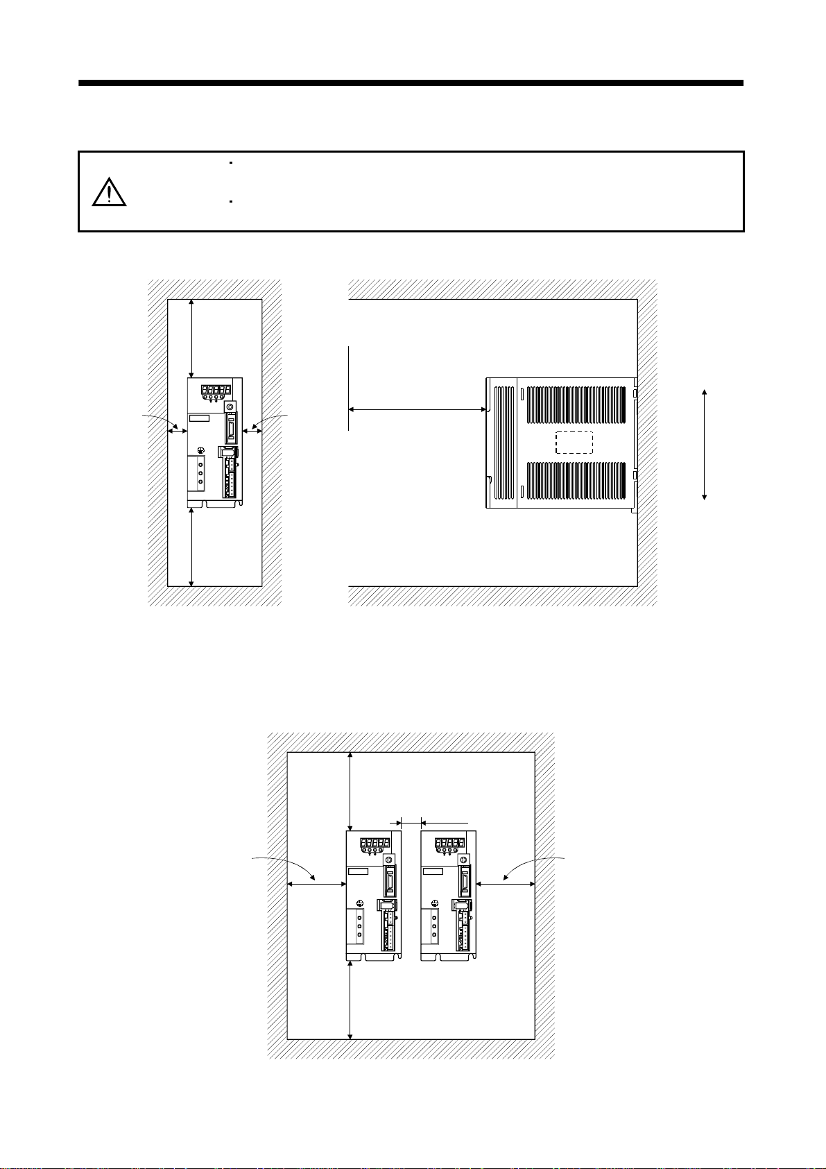
2.2 Installation direction and clearances The equipment mus t be installe d in the specif ied direc tion. Other wise, a fau lt ma y
CAUTION
(1) Installation of one servo amplifier
Control box Control box
10mm
(0.4 in.)
or more
MODE
MITSUBISHI
MR-
occur.
Leave specified clearances between the servo amplifier and control box inside
walls or other equipment.
40mm
(1.6 in.)
or more
Servo
amplifier
SET
CN3
CN1
CN2
CNP2
CNP1
L3L2 L1 D C P W V U
40mm
(1.6 in.)
or more
CHARGE
10mm
(0.4 in.)
or more
Wiring clearance
(2.8 in.)
70mm
Top
Bottom
(2) Installation of two or more servo amplifiers
Leave a large clearance between the top of the servo amplifier and the internal surface of the control
box, and install a fan to prevent the internal temperature of the control box from exceeding the
environmental conditions.
Control box
30mm
(1.2 in.)
or more
100mm
(4.0 in.)
or more
MODE
CN3
MITSUBISHI
MR-
CN1
CN2
CNP2
CNP1
40mm
(1.6 in.)
or more
SET
L3L2 L1 D C P W V U
CHARGE
10mm
(0.4 in.)
or more
MODE
CN3
MITSUBISHI
MR-
CN1
CN2
CNP2
CNP1
SET
30mm
(1.2 in.)
or more
CHARGE
L3L2 L1 D C P W V U
2 - 2
Page 30

2. INSTALLATION
(3) Others
When using heat generating equipment such as the regenerative brake option, install them with full
consideration of heat generation so that the servo amplifier is not affected.
Install the servo amplifier on a perpendicular wall in the correct vertical direction.
2.3 Keep out foreign materials
(1) When installin g the unit in a control box, prevent drill ch ips and wire fragmen ts from entering the
servo amplifier.
(2) Prevent oil, water, metallic dust, etc. from entering the servo amplifier through openings in the control
box or a fan installed on the ceiling.
(3) When insta lling the co ntrol box in a place whe re there are much toxic g as, dirt and dust, conduct an
air purge (force clean air into the contro l box from outside to make the internal pressure higher than
the external pressure) to prevent such materials from entering the control box.
2.4 Cable stress
(1) The way of clamping the cable must be fully examined so that flexing stress and cable's own weight
stress are not applied to the cable connection.
(2) For use in any application where the servo motor moves, fix the cables (encoder, power supply, brake)
supplied with the servo motor, and flex the optional encoder cable or the power supply and brake
wiring cables. Use the optional encoder cable within the flexing life range. Use the power supply and
brake wiring cables within the flexing li fe of the cabl es.
(3) Avoid any probability that the cable sheath might be cut by sharp chips, rubbed by a machine corner
or stamped by workers or vehicles.
(4) For installation on a machine where the servo motor will move, the flexing radius should be made as
large as possible. Refer to section 12.4 for the flexing life.
2 - 3
Page 31

2. INSTALLATION
MEMO
2 - 4
Page 32

3. SIGNALS AND WIRING
3. SIGNALS AND WIRING
Any person who is involved in wiring should be fully competent to do the work.
Before starting wiring, switch power off, then wait for more than 10 minutes, and
after the charge lamp has gone off, make sure that the voltage is safe in the tester
or like. Otherwise, you may get an electric shock.
WARNING
Ground the servo amplifier and the servo motor securely.
Do not attempt to wire the servo amplifier and servo motor until they have been
installed. Otherwise, you may get an electric shock.
The cables should not be damaged, stressed excessively, loaded heavily, or
pinched. Otherwise, you may get an electric shock.
Wire the equipment correctly and securely. Otherwise, the servo motor may
misoperate, resulting in injury.
Connect cables to correct terminals to prevent a burst, fault, etc.
Ensure that polarity ( , ) is correct. Otherwise, a burst, damage, etc. may occur.
The surge absorbing diode installed to the DC relay designed for control output
should be fitted in the specified direction. Otherwise, the signal is not output due to
a fault, disabling the emergency stop and other protective circuits.
Servo
Amplifier
External
24VDC
Servo
Amplifier
External
24VDC
CAUTION
Control output
signal
RA
Control output
signal
RA
Use a noise filter, etc. to minimize the influence of electromagnetic interference,
which may be given to electronic equipment used near the servo amplifier.
Do not install a power capacitor, surge suppressor or radio noise filter (FR-BIF
option) with the power line of the servo motor.
When using the regenerative brake resistor, switch power off with the alarm signal.
Otherwise, a transistor fault or the like may overheat the regenerative brake
resistor, causing a fire.
Do not modify the equipment.
3 - 1
Page 33

3. SIGNALS AND WIRING
3.1 Standard connection example
POINT
Refer to Section 3.7.1 for the connection of the power supply system and to
Section 3.8 for connection with the servo motor.
3.1.1 Position control mode
(1) FX-10GM
Positioni n g modu l e
FX-10GM
PGO
24
VC
FPO
FP
RP
RPO
CLR
STOP
ZRN
FWD
RVS
DOG
LSF
LSR
1
2
12
11
14
13
7,17
8,18
5
6
9,19
16
15
3
4
1
2
3
4
5
6
7
8
9,19
SVRDY
COM2
COM2
SVEND
COM4
COM5
COM3
START
COM1
(Note 3, 5) Emergency stop
Servo-on
Reset
(Note 5) Forward rotation stroke end
Reverse rotation stroke end
(Note 9) 2m(6.5ft) max.
10m(32ft) max.
RD
VIN
INP
VIN
OP
LG
OPC
VIN
PP
SG
NP
CR
SG
SD
EMG
SON
RES
LSP
LSN
SG
Servo amplifier
(Note 8)
CN1
11
1
10
1
21
14
2
1
23
13
25
5
13
(Note 8)
Plate
(Note 8)
(Note 8)
CN1
8
4
3
6
7
13
(Note 8)
CN1
1VIN
9
12
13 SG
CN1
15
16
17
18
19
20
Plate
CN3
4
3
6
Plate
ALM
ZSP
LA
LAR
LB
LBR
LZ
LZR
SD
MO1
LG
MO2
SD
(Note2, 4)
RA1
RA2
A
A
2m (6.5ft) max.
Trouble
(Note 6)
Zero speed
Encoder A-phase pulse
(differential line driver)
Encoder B-phase pulse
(differential line driver)
Encoder Z-phase pulse
(differential line driver)
(Note 7)
10k
Monitor output
Max. 1mA
Reading in both
10k
directions
(Note 11)
External
power
supply
24VDC
(Note 10)
Servo configuration
software
Personal
computer
(Note 7)
Communication cable
3 - 2
(Note 8)
CN3
(Note 1)
Page 34

3. SIGNALS AND WIRING
Note: 1. To prevent an electric shock, always connect the protective earth (PE) terminal (t erminal mark ed ) of the servo amplifier to
the protective earth (PE) of the control box.
2. Connect the diode in the correct direction. If it is connected reversely, the servo amplifier will be faulty and will not output
signals, disabling the emergency stop and other protective circuits.
3. The emergency stop switch (normally closed contact) must be installed.
4. The sum of currents that flow in the external relays should be 80mA max. If it exceeds 80mA, supply interface power from
external. (Refer to Section 3.6.2)
5. When starting operation, always connect the emergency stop signal (EMG) and forward/ reverse rotation stroke end signal
(LSN/LSP) with SG. (Normally closed contacts)
6. Trouble (ALM) is connected with COM in normal alarm-free condition. When this signal is switched off (at occurrence of an
alarm), the output of the controller should be stopped by the sequence program.
7. When connecting the personal computer together with monitor outputs 1, 2, use the branch cable (MR-E3CBL15-P). (Refer to
Section 13.1.3)
8. The pins with the same signal name are connected in the servo amplifier.
9. This length applies to the command pulse train input in the opencollector system. It is 10m (32ft) or less in the differential line
driver system.
10. Use MRZJW3-SETUP 154E.
11. Connect the external 24VDC power supply if the output signals are not used.
3 - 3
Page 35

3. SIGNALS AND WIRING
(2) AD75P (A 1SD75P )
Positioning module
AD75P
(A1SD75P )
READY
COM
INPS
PGO(24V)
PGO(5V)
PGO COM
CLEAR
CLEAR COM
PULSE FPULSE F+
PULSE R-
PULSE R+
PULSE F
PULSE COM
PULSE R
PULSE COM
DOG
FLS
RLS
STOP
CHG
START
COM
COM
7
26
8
6
24
25
5
23
21
3
22
4
1
19
2
20
11
12
13
14
15
16
35
36
(Note 9) 10m(32ft) max.
(Note 11)
24VDC
RD
VIN
INP
LZ
LZR
CR
SG
PG
PP
NG
NP
LG
SD
Servo amplifier
(Note 8)
CN1
11
1
10
19
20
5
13
22
23
24
25
14
Plate
(Note 8)
CN1
1VIN
9
12
13 SG
(Note 8)
CN1
15
16
17
18
14
21
Plate
ALM
ZSP
LA
LAR
LB
LBR
LG
OP
SD
(Note 2, 4)
RA1
RA2
Encoder A-phase pulse
(differential line driver)
Encoder B-phase pulse
(differential line driver)
Control common
Encoder Z-phase pulse
(open collector)
Trouble
(Note 6)
Zero speed
(Note 12)
External
power
supply
24VDC
(Note 3, 5) Emergency stop
Servo-on
Reset
(Note 5) Forward rotation stroke end
Reverse rotation stroke end
(Note 10)
Servo configuration
software
Personal
computer
(Note 7)
Communication cable
EMG
SON
RES
LSP
LSN
SG
(Note 8)
CN1
8
4
3
6
7
13
(Note 8)
CN3
(Note 8)
CN3
4
3
6
Plate
MO1
LG
MO2
SD
(Note 1)
A
A
2m(6.5ft) max.
10k
10k
(Note 7)
Monitor output
Max. 1mA
Reading in both
directions
3 - 4
Page 36

3. SIGNALS AND WIRING
Note: 1. To prevent an electric shock, always connect the protective earth (PE) terminal (t erminal mark ed ) of the servo amplifier to
the protective earth (PE) of the control box.
2. Connect the diode in the correct direction. If it is connected reversely, the servo amplifier will be faulty and will not output
signals, disabling the emergency stop and other protective circuits.
3. The emergency stop switch (normally closed contact) must be installed.
4. The sum of currents that flow in the external relays should be 80mA max. If it exceeds 80mA, supply interface power from
external.(Refer to Section 3.6.2)
5. When starting operation, always connect the emergency stop signal (EMG) and forward/ reverse rotation stroke end signal
(LSN/LSP) with SG. (Normally closed contacts)
6. Trouble (ALM) is connected with COM in normal alarm-free condition. When this signal is switched off (at occurrence of an
alarm), the output of the controller should be stopped by the sequence program.
7. When connecting the personal computer together with monitor outputs 1, 2, use the branch cable (MR-E3CBL15-P). (Refer to
Section 13.1.3)
8. The pins with the same signal name are connected in the servo amplifier.
9. This length applies to the command pulse train input in the differential line driver system.
It is 2m (6.5ft) or less in the opencollector system.
10. Use MRZJW3-SETUP 154E.
11. Connect LG and pulse output COM to increase noise immunity.
12. Connect the external 24VDC power supply if the output signals are not used.
3 - 5
Page 37

3. SIGNALS AND WIRING
(3) QD75D (differential driver)
Positioning module
QD75D
READY
RDY COM
PGO5
PGO COM
CLEAR
CLEAR COM
PULSE FPULSE F+
PULSE RPULSE R+
COM
COM
DOG
FLS
RLS
STOP
CHG
PULSER A+
PULSER A-
PULSER B+
PULSER B-
11
12
9
10
13
14
16
15
18
17
6
7
3
1
2
4
5
A19
B19
A20
B20
Manual pulse
generator
MR-HDP01
(Note 9) 10m(32ft) m ax.
External power
supply 24VDC
5V
5V
A
B
0V
5G
RD
VIN
LZ
LZR
CR
SG
PG
PP
NG
NP
LG
SD
Servo amplifier
(Note 8)
CN1
11
1
19
20
5
13
22
23
24
25
14
Plate
(Note 8)
(Note 8)
CN1
1VIN
9
ALM
12
ZSP
13 SG
CN1
15
LAR
16
17
LBR
18
14
21
Plate
LA
LB
LG
OP
SG
(Note 2, 4)
RA1
RA2
Encoder A-phase pulse
(differential line driver)
Encoder B-phase pulse
(differential line driver)
Control common
Encoder Z-phase pulse
(open collector)
Trouble
(Note 6)
Zero speed
(Note 11)
External
power
supply
24VDC
(Note 3, 5) Emergency stop
Servo-on
Reset
(Note 5) Forward rotation stroke end
Reverse rotation stroke end
(Note 10)
Servo configuration
software
Personal
computer
(Note 7)
Communication cable
(Note 8)
CN1 CN3
EMG
SON
RES
LSP
LSN
SG
(Note 8)
CN3
(Note 8)
8
4
3
6
7
13
4
MO1
3
LG
6
MO2
SD
Plate
2m(6.5ft) max.
(Note 1)
A
A
10k
10k
(Note 7)
Monitor output
Max. 1mA
Reading in both
directions
3 - 6
Page 38

3. SIGNALS AND WIRING
Note: 1. To prevent an electric shock, always connect the protective earth (PE) terminal (t erminal mark ed ) of the servo amplifier to
the protective earth (PE) of the control box.
2. Connect the diode in the correct direction. If it is connected reversely, the servo amplifier will be faulty and will not output
signals, disabling the emergency stop and other protective circuits.
3. The emergency stop switch (normally closed contact) must be installed.
4. The sum of currents that flow in the external relays should be 80mA max. If it exceeds 80mA, supply interface power from
external.(Refer to Section 3.6.2)
5. When starting operation, always connect the emergency stop signal (EMG) and forward/ reverse rotation stroke end signal
(LSN/LSP) with SG. (Normally closed contacts)
6. Trouble (ALM) is connected with COM in normal alarm-free condition. When this signal is switched off (at occurrence of an
alarm), the output of the controller should be stopped by the sequence program.
7. When connecting the personal computer together with monitor outputs 1, 2, use the branch cable (MR-E3CBL15-P). (Refer to
Section 13.1.3)
8. The pins with the same signal name are connected in the servo amplifier.
9. This length applies to the command pulse train input in the differential line driver system.
It is 2m (6.5ft) or less in the opencollector system.
10. Use MRZJW3-SETUP 154E.
11. Connect the external 24VDC power supply if the output signals are not used.
3 - 7
Page 39

3. SIGNALS AND WIRING
3.1.2 Internal speed control mode
(Note 3, 5) Emergency stop
Servo-on
Forward rotation start
Reverse rotation start
(Note 5) Forward rotation stroke end
Reverse rotation stroke end
10m(32ft) max.
EMG
SON
ST1
ST2
LSP
LSN
SG 13
Servo amplifier
(Note 8)
CN1
(Note 8)
CN1
8
4
3
5
6
7
1
9
12
10 SA
11
13 SG
19
20
15
16
17
18
14
21
Plate
VIN
ALM
ZSP
RD
LZ
LZR
LA
LAR
LB
LBR
LG
OP
SD
(Note 2, 4)
RA1
RA2
RA5
RA4
Encoder Z-phase pulse
(differential line driver)
Encoder A-phase pulse
(differential line driver)
Encoder B-phase pulse
(differential line driver)
Control common
Encoder Z-phase pulse
(open collector)
Trouble
(Note 6)
Zero speed
Speed reached
Ready
(Note 10)
External
power
supply
24VDC
(Note 8)
CN3
10k
10k
(Note 7)
Monitor output
Max. 1mA
Reading in
both directions
(Note 9)
Servo configuration
software
Personal
computer
(Note 7)
Communication cable
(Note 8)
CN3
4
3
6
Plate
MO1
LG
MO2
SD
(Note 1)
A
A
2m(6.5ft) max.
Note: 1. To prevent an electric shock, always connect the protective earth (PE) terminal (t erminal mark ed ) of the s ervo amplifier to
the protective earth (PE) of the control box.
2. Connect the diode in the correct direction. If it is connected reversely, the servo amplifier will be faulty and will not output
signals, disabling the emergency stop and other protective circuits.
3. The emergency stop switch (normally closed contact) must be installed.
4. The sum of currents that flow in the external relays should be 80mA max. If it exceeds 80mA, supply interface power from
external.(Refer to Section 3.6.2)
5. When starting operation, always connect the emergency stop signal (EMG) and forward/ reverse rotation stroke end signal
(LSN/LSP) with SG. (Normally closed contacts)
6. Trouble (ALM) is connected with COM in normal alarm-free condition.
7. When connecting the personal computer together with monitor outputs 1, 2, use the branch cable (MR-E3CBL15-P). (Refer to
Section 13.1.3)
8. The pins with the same signal name are connected in the servo amplifier.
9. Use MRZJW3-SETUP 154E.
10. Connect the external 24VDC power supply if the output signals are not used.
3 - 8
Page 40

3. SIGNALS AND WIRING
3.2 Internal connection diagram of servo amplifier
The following is the internal connection diagram where the signal assignment has been made in the
initial status in each control mode.
Servo amplifier
(Note)
PS
CN1
INP SA10
RD RD11CR
ALM ALM9
ZSP ZSP12
CN1
15
LA
16
LAR
17
LB
18
LBR
19
LZ
20
LZR
21
OP
LG14
CN3
4MO1
External
power
supply
24VDC
(Note)
S
P
VIN VIN 1
ST2 5
SON SON 4
RES
ST1
EMG
EMG
LSP
LSP
LSN
LSN
SG
SG
OPC
PG
PP
NG
NP
SD
SD
CN1
3
8
6
7
13
2
22
23
24
25
Case
Approx. 100k
Approx. 100k
Approx. 4.7k
Approx. 4.7k
Approx. 4.7k
Approx. 4.7k
Approx. 4.7k
Approx. 4.7k
Approx. 1.2k
Approx. 1.2k
Note. P: Position control mode, S: Internal speed control mode
62MO2
TXD
1RXD
3LG
SD
Case
PE
3 - 9
Page 41

3. SIGNALS AND WIRING
3.3 I/O signals
3.3.1 Connectors and signal arrangements POINT
The pin configurations of the connectors are as viewed from the cable
connector wiring section.
Refer to the next page for CN1 signal assignment.
(1) Signal arrangement
5 3
6
MO2
2LG4
MRR
1
3MR57MD9
P5
LG1RXD
4
MO1
68
MDR
2
TXD2TXD
10
LG
MODE
MITSUBISHI
MR-E
CNP2
CNP1
The connector frames are
connected with the PE (earth)
terminal inside the servo amplifier.
SET
CN3
CN1
CN2
CHARGE
L3L2L1 D C P W V U
2
OPC
4
SON
6
LSP
8
EMG
10
INP
12
ZSP
1
VIN
3
RES
5
CR
7
LSN
9
ALM
11
RD
SG
CN1
15
LA
17
LB
19
LZ
21
OP
23
PP
25
NP
14
LG
16
LAR
18
LBR
20
LZR
22
PG
24
NG
2613
3 - 10
Page 42

3. SIGNALS AND WIRING
(2) CN1 signal assignment
The signal assignment of connector changes with the control mode as indicated below;
For the pins which are given parameter No.s in the related parameter column, their signals can be
changed using those parameters.
Connector Pin No. (Note1) I/O
1 VIN VIN VIN
2OPCOPC
3 I RES RES/ST1 ST1 No.43 to 48
4I SON SON
5I CR LOP
6 I LSP LSP LSP No.43 48
7I LSN LSN LSN No.4348
8 I EMG EMG EMG
9O ALM ALM ALM No.49
10 O INP INP/SA SA No.49
11 O RD RD RD No.49
12 O ZSP ZSP ZSP No.1, 49
CN1
Note: 1. I : Input signal, O: Output signal
2. P : Position control mode, S: Internal speed control mode, P/S: Position/internal speed control change mode.
13 SG SG SG
14 LG LG LG
15 O LA LA LA
16 O LAR LAR LAR
17 O LB LB LB
18 O LBR LBR LBR
19 O LZ LZ LZ
20 O LZR LZR LZR
21 O OP OP OP
22 I PG PG/
23 I PP PP/
24 I NG NG/
25 I NP NP/
26
(Note2) I/O Signals in control modes
PP/SS
SON
ST2
Related
parameter
No.43 to 48
No.43 to 48
3 - 11
Page 43

3. SIGNALS AND WIRING
(3) Symbols and sig na l na mes
Symbol Signal name Symbol Signal name
SON Servo-on ZSP Zero speed
LSP Forward rotation stroke end INP In position
LSN Reverse rotation stroke end SA Speed reached
CR Clear ALM Trouble
SP1 Speed selection 1 WNG Warning
SP2 Speed selection 2 OP Encoder Z-phase pulse (open collector)
PC Proportion control MBR Electromagnetic brake interlock
ST1 Forward rotation start LZ
ST2 Reverse rotation start LZR
TL Torque limit selection LA
RES Reset LAR
EMG Emergency stop LB
LOP Control change LBR
PP VIN Digital I/F power supply input
NP OPC Open collector power input
PG SG Digital I/F common
NG
RD Ready SD Shield
Forward/reverse rotation pulse train
LG Control common
Encoder Z-phase pulse
(differential line driver)
Encoder A-phase pulse
(differential line driver)
Encoder B-phase pulse
(differential line driver)
3 - 12
Page 44

3. SIGNALS AND WIRING
3.3.2 Signal explanations
For the I/O interfaces (symbols in I/O column in the table), refer to Section 3.6.2.
In the control mode field of the table
P : Position control mode, S: Internal speed control mode
: Denotes that the signal may be used in the initial setting status.
: Denotes th a t th e signal may be u se d by se t ting the corre spo n d in g pa r ameter among parameters 43 to
49.
The pin No.s in the connector pin No. column are those in the initial status.
(1) Input si gn al s
POINT
The acceptance delay time of each input signal is less than 10ms.
Connec-
Signal Symbol
Servo-on SON CN1-4 Connect SON-SG to switch on the base c i rcuit and make the ser vo
Reset RES CN1-3 Disconnect RES-SG for more than 50ms to reset the alarm.
Forward rotation
stroke end
Reverse rotation
stroke end
LSP CN1-6
LSN CN1-7
tor pin
No.
Functions/Applications
amplifier ready to operate (servo-on).
Disconnect SON-SG to shut off the base circuit and coast the
servo motor (servo off) .
Set "
1" in pa rameter No. 41 to switch thi s si gnal on
(keep te rminals connected) automatically in th e servo
amplifier.
Some alarms cannot be deactivated by the reset signal. (Refer to
Section 10.2.1.)
Shorting RES-SG in an alarm-free status shuts off the base
circuit. The base circuit is not shut off when "
parameter No. 51.
To start operation, short LSP-SG and/or LSN-SG. Open them to
bring the motor to a sudden stop and make it servo-locked.
Set "
1" in parameter No. 22 to make a slow stop.
(Refer to Section 5.2.3.)
(Note) Input signals Operation
LSP LSN
11
01
10
00
Note. 0: LSP/LSN-SG off (open)
1: SP/LSN-SG on (short)
Set parameter No. 41 as indicated below to switch on the signals
(keep terminals connected) automatically in the servo amplifier:
Parameter No.41 Automatic ON
1 LSP
1 LSN
CCW
directionCWdirection
1 " is set in
I/O
division
DI-1
DI-1
DI-1
Control
mode
PS
3 - 13
Page 45

3. SIGNALS AND WIRING
Connec-
Signal Symbol
Internal
torque limit
selection
Forward rotation
start
Reverse rotation
start
Speed selection 1 SP1 <Internal speed control m ode>
Speed selection 2 SP2
Speed selection 3 SP3
Proportion
control
TL1 When using this signal, make it usable by making the setting of
ST1 CN1-3
ST2 CN1-5
PC Connect PC-SG to switch the speed amplifier from the proportional
tor pin
No.
Functions/Applications
parameter No. 43 to 48.
(Refer to (5), Section 3.4.1.)
Used to start the servo motor in any of the following directions:
(Note) Input signals
ST2 ST1
0 0 Stop (servo lock)
0 1 CCW
10 CW
1 1 Stop (servo lock)
Note. 0: ST1/ST2-SG off (open)
1: ST1/ST2-SG on (short)
If both ST1 and ST2 are switched on or off during operation, the
servo motor will be decelerated to a stop according to the parameter
No. 12 setting and servo-locked.
Used to select the command sp e ed f or op era t ion.
When using SP1 to SP3, make it usable by making the setting of
parameter No. 43 to 48.
(Note) Input signals
SP3 SP2 SP1
00 0
0 0 1 Internal speed command 1 (parameter No. 8)
0 1 0 Internal speed command 2 (parameter No. 9)
0 1 1 Internal speed command 3 (pa rameter No. 10 )
10 0
1 0 1 Internal speed command 5 (pa rameter No. 73 )
1 1 0 Internal speed command 6 (pa rameter No. 74 )
1 1 1 Internal speed command 7 (pa rameter No. 75 )
Note 0: SP1/SP2/SP3-SG off (open)
1: SP1/SP2/SP3-SG o n ( sh o r t)
integral type to the proportional type.
If the servo motor at a stop is rotated even one pulse due to any
external factor, it generates torque to compensate for a position
shift. When the servo motor shaft is to be locked mechanically after
positioning completion (stop), switching on the proportion control
signal (PC) upon positioning completion will suppress the
unnecessary torque generated to compensate for a position shift.
When the shaft is to be locked for a long time, switch on the
proportion control signal and torque control signal (TL) at the same
time to make the torque less than the rated by the analog torque
limit.
Internal speed command 1 (parameter No. 8) DI-1
Internal speed command 4 (parameter No. 72)
Servo motor starting direction
Speed command
I/O
division
DI-1
DI-1
DI-1
DI-1
DI-1
Control
mode
PS
3 - 14
Page 46

3. SIGNALS AND WIRING
Connec-
Signal Symbol
Emergency stop EMG CN1-8 Disconnect EMG-SG to bring the servo motor to emergency stop
Clear CR CN1-5 Connect CR-SG to clear the position control counter droop pulses on
Electronic gear
selection 1
Electronic gear
selection 2
Gain changing CDP When using this signal, make it usable by the setting of parameter
Control change LOP <Positi on/i nternal sp e ed cont rol change mode>
Forward rotation
pulse train
Reverse rotation
pulse train
CM1 When using CM1 and CM2, make them usable by the setting of
CM2
PP
NP
PG
NG
tor pin
No.
CN1-23
CN1-25
CN1-22
CN1-24
Functions/Applications
state, in which the servo is switched off and the dynamic brake is
operated.
Connect EMG-SG in the emergency stop state to reset that state.
its leading edge. The pulse width should be 10ms or more.
When the parameter No.42 setting is "
cleared while CR- SG a re connected.
parameters No. 43 to 48.
The combination of CM1-SG and CM2-SG gives you a choice of four
different electronic gear numerators set in the parameters.
CM1 and CM2 cannot be used in the absolute position detection
system.
(Note) Input signals
CM2 CM1
00 Parameter No. 3
01 Parameter No. 69
10 Parameter No. 70
11 Parameter No. 71
Note.0: CM1/CM2-SG off (open)
1: CM1/CM2-SG on (short)
No. 43 to 48.
Connect CDP-SG to change the load inertia moment ratio into the
parameter No. 61 setting and the gain values into the values
multiplied by the parameter No. 62 to 64 settings.
Used to select the control mode in the position/internal speed
control change mode.
(Note) LOP Control mode
0Position
1 Internal speed
Note.0: LOP-SG off (open)
1: LOP-SG on (short)
Used to enter a command puls e t ra i n.
In the open collector system (max. input frequency 200kpps):
Forward rotation pulse train across PP-SG
Reverse rotation pulse train across NP-SG
In the differential receiver system (max. input frequency 500kpps):
Forward rotation pulse train across PG-PP
Reverse rotation pulse train across NG-NP
The command pulse train f o rm ca n b e cha nged using
parameter No. 21.
1 ", the pulses are al w a y s
Electronic gear namerator
I/O
division
DI-1
DI-1
DI-1
DI-1
DI-1
DI-1
DI-2
Control
mode
PS
Refer to
Functions/
Appli-
cations.
3 - 15
Page 47

3. SIGNALS AND WIRING
(2) Output signals
Connec-
Signal Symbol
Trouble ALM CN1-9 ALM-SG are disconnected when power is switched off or the
Ready RD CN1-11 RD-SG are connected when the servo is switched on and the servo
In position INP INP-SG are connected when the number of droop pulses is in the
Speed reach ed SA
Zero speed ZSP CN1-12 ZSP-SG are connected when the servo motor speed is zero speed
Electromagnetic
brake interlock
Warning WNG To use this signal, assign the connector pin for output using
MBR
tor pin
No.
CN1-10
(CN1-12)
Functions/Applications
protective circuit is activated to shut off the base circuit. Without
alarm, ALM-SG are connected within 1 after power on.
amplifier is ready to operate.
preset in-position range. The in-position range can be changed
using parameter No. 5.
When the in-position range is increased, INP-SG may be kept
connected during low-speed rotation.
SA-SG are connected when the servo motor speed has nearly
reached the preset speed. When the preset speed is 50r/min or
less, SA-SG are kept connec ted.
(50r/min) or less. Zero speed can be changed using parameter No.
24.
Set " 1 " in parameter No. 1 to use this parameter. Note that
ZSP will be unusable.
In the servo-off or alarm status, MBR-SG are disconnected.
When an alarm occurs, they are disconnected independently of
the base circuit status.
parameter No.49. The old signal before assignment will be
unusable.
When warning has occurred, WNG-SG are connected.
When there is no warning, WNG-SG are disconnected within 1
second after power-on.
I/O
division
DO-1
DO-1
DO-1
DO-1
DO-1
DO-1
DO-1
Control
mode
PS
3 - 16
Page 48

3. SIGNALS AND WIRING
Signal Symbol
Alarm code ACD 0
ACD 1
ACD 2
Connec-
tor pin
No.
Functions/Applications
To use this signal, set " 1" in parameter No.49.
This signal is output when an alarm occurs. When there is no
alarm, respective ordinary signals (RD, INP, SA, ZSP) are output.
Alarm codes and alarm names are listed below:
(Note) Alarm code
CN1
CN1
CN1
12 Pin
11 Pin
000
010
001AL.10Undervoltage
011
100
110
101
Note.0: Pin-SG off (open)
1: Pin-SG on (short)
10 Pin
Alarm
display
88888 Watchdog
AL.12 Memory error 1
AL.13 Clock error
AL.15 Memory error 2
AL.17 Board error
AL.19 Memory error 3
AL.37 Parameter error
AL.8A
AL.8E Serial communication error
AL.30 Regenerative error
AL.33 Overvoltage
AL.45 Main circuit device
AL.46 Servo motor overheat
AL.50 Overload 1
AL.51 Overload 2
AL.24 Main circuit error
AL.32 Overcurrent
AL.31 Overspeed
AL.35
AL.52 Error exc essi ve
AL.16 Encoder error 1
AL.1A Monitor combination error
AL.20 Encoder error 2
Serial communication
timeout
Command pulse frequency
alarm
Name
I/O
division
DO-1
Control
mode
PS
3 - 17
Page 49

3. SIGNALS AND WIRING
Connec-
Signal Symbol
Encoder Z-phase
pulse
(Open collector)
Encoder A-phase
pulse
(Differential line
driver)
Encoder B-phase
pulse
(Differential line
driver)
Encoder Z-phase
pulse
(Differential line
driver)
Analog monitor 1 MO1 CN3-4 Used to output the data set in parameter No.17 to across MO1-LG
Analog monitor 2 MO2 CN3-6 Used to output the data set in parameter No.17 to across MO2-LG
OP CN 1-21 Out puts the zero-point signal of the encoder. One pul se is output
LA
LAR
LB
LBR
LZR
LZ
tor pin
No.
CN1-15
CN1-16
CN1-17
CN1-18
CN1-19
CN1-20
Functions/Applications
per servo motor revo lution. OP and LG are connec ted when the
zero-point position is reached. (Negative logic)
The minimum pulse width is about 400
return using this pulse, set the creep speed to 100r/min. or less.
Outputs pulses per servo motor revolution set in parameter No.
27 in the differential line driver system. In CCW rotation of the
servo motor, the encoder B-phase pulse lags the encoder A-phase
pulse by a phase angle of
The relationships between rotation direction and phase difference
of the A- and B-phase pulses c an be c hange d usi ng par ame ter No .
54.
The same signal as OP is output in the differential line driver
system.
in terms of voltage. Resolution 10 bits
in terms of voltage. Resolution 10 bits
/2.
s. For home position
I/O
division
DO-2
DO-2
DO-2
Analog
output
Analog
output
Control
mode
PS
(3) Communication
Connec-
Signal Symbol
RS-232C I/F RXD
TXD
tor pin
No.
CN3-1
CN3-2
Functions/Applications
RS-232C communication interface.
(4) Power supply
Connec-
Signal Symbol
Digital I/F power
supply input
Open collector
power input
Digital I/F
common
Control common LG CN1-14 Common terminal for OP, MO1, and MO2.
Shield SD Plate Connect the external conductor of the shield cable.
VIN CN1-1 Used to input 24VDC for input interface.
OPC CN1-2 When inputting a pulse train in the open collector system, supply
SG CN 1-13 Commo n terminal for input signals such as SON and EMG. Pins
tor pin
No.
Functions/Applications
Connect the positive terminal of the 24VDC external power
supply.
24VDC
this terminal with the positive (
are connected internally.
Separated from LG.
Pins are connecte d internally.
10%
) power of 24VDC.
I/O
division
I/O
division
Control
mode
PS
Control
mode
PS
3 - 18
Page 50

3. SIGNALS AND WIRING
3.4 Detailed description of the signals
3.4.1 Position control mode (1) Pulse trai n inpu t
(a) Input pulse waveform selection
Encoder pulses may be input in any of three different forms, for which positive or negative logic
can be chosen. Set the command pulse train form in parameter No. 21.
Arrow
A- and B-phase pulse trains are imported after they have been multi pli ed b y 4.
or in the table indicates the timing of importing a pulse train.
Pulse train form
Forward rotation
pulse train
Reverse rotation
pulse train
Pulse train sign
Negative logic
A-phase pulse train
B-phase pulse train
Forward rotation
pulse train
Reverse rotation
pulse train
Pulse train sign
Positive logic
A-phase pulse train
B-phase pulse train
Forward rotation
command
PP
NP
PP
NP
PP
NP
PP
NP
PP
NP
PP
NP
Reverse rotation
command
L
H
H
L
Parameter No. 21
(Command pulse train)
0010
0011
0012
0000
0001
0002
3 - 19
Page 51

3. SIGNALS AND WIRING
(b) Connections and waveforms
1) Open collector system
Connect as shown below:
The explanation assumes that the input waveform has b een set to the negati ve logi c and forward
and reverse rotation pulse trains (parameter No.21 has been set to 0010). The waveforms in the
table in (a), (1) of this section are voltage waveforms of PP and NP based on SG. Their
relationships with transistor ON/OFF are as follows:
Forward rotation
pulse train
(transistor)
Reverse rotation
pulse train
(transistor)
Servo amplifier
External power
supply 24VDC
(ON)(OFF)
Forward rotation command Reverse rotation command
(ON)(OFF)
(OFF)
OPC
PP
NP
SG
SD
Approx.
1.2k
Approx.
1.2k
(OFF)
(ON) (OFF) (ON) (OFF) (ON)
3 - 20
Page 52

3. SIGNALS AND WIRING
2) Differential line driver system
Connect as shown below:
The explanation assumes that the input waveform has b een set to the negati ve logi c and forward
and reverse rotation pulse trains (parameter No.21 has been set t o 0010 ).
For the differential line driver, the waveforms in the table in (a), (1) of this section are as follows.
The waveforms of PP, PG, NP and NG are based on that of the ground of the differential line
driver.
Servo amplifier
PP
PG
NP
NG
SD
Forward rotation
pulse train
PP
PG
Reverse rotation
pulse train
NP
NG
Forward rotation command Reverse rotation command
3 - 21
Page 53

3. SIGNALS AND WIRING
(2) In-position (INP)
PF-SG are connected when the number of droop pulses in the deviation counter falls within the preset
in-position range (parameter No. 5). INP-SG may remain connected when low-speed operation is
performed with a large value set as the in-position range.
Servo-on (SON)
ON
OFF
Alarm
Droop pulses
In position (INP)
Yes
No
In-position range
ON
OFF
(3) Ready (RD)
Servo-on (SON)
Alarm
Ready (RD)
ON
OFF
Yes
No
ON
OFF
80ms or less 10ms or less 10ms or less
(4) Electronic gear switching
The combination of CM1-SG and CM2-SG gives you a choice of four different electronic gear
numerators set in the parameters.
As soon as CM1/CM2 is turned ON or OFF, the namerator of the electronic gear changes. Therefore, if
any shock occurs at this change, use position smoothing (parameter No. 7) to relieve shock.
(Note) External input signal
CM2 CM1
00 Parameter No. 3
01 Parameter No. 69
10 Parameter No. 70
11 Parameter No. 71
Note.0: CM1/CM2-SG off(open)
1: CM1/CM2-SG on(short)
Electronic gear namerator
3 - 22
Page 54

3. SIGNALS AND WIRING
(5) Torque limit
(a) Torque limit and torque
By setting param eter No. 28 (interna l torque limit 1), to rque is always limi ted to the maximum
value during operation. A relationship between the limit value and servo motor torque is shown
below.
(b) Torque limit value selection
When internal torque limit selection (TL1) is made usable by parameter No. 43 to 48, internal
torque limit 2 (paramete r No. 76) can be selected. However, if the p arameter No. 28 v alue is less
than the limit value selected by parameter No.76, the parameter No. 28 value is made valid.
(Note) External input signals
TL1
0 Internal torque limit value 1 (parameter No. 28)
1
Note.0: TL/TL1-SG off (open)
1: TL/TL1-SG on (short)
Max. torque
Parameter No. 76
Parameter No. 76
Torque
0
0 100
Torque limit value [%]
Torque limit value made valid
Parameter No. 28: Parameter No. 28
Parameter No. 28: Parameter No. 76
3 - 23
Page 55

3. SIGNALS AND WIRING
3.4.2 Internal speed control mode (1) Speed setting
(a) Speed command and speed
The servo motor is run at the speeds set in the parameters.
The following ta ble indicates the rota tion direction accor ding to forward rotation start ( ST1) and
reverse rotation start (ST2) combination:
(Note) External input signals Rotation direction
ST2 ST1
00 Stop (Servo lock)
01 CCW
10 CW
11 Stop (Servo lock)
Note.0: ST1/ST2-SG off (open)
1: ST1/ST2-SG on (short)
Forward rotation (CCW)
Reverse rotation (CW)
Internal speed commands
The forward rotation start signal (ST1) and reverse rotation start signal (ST2) can be assigned to
any pins of the connector CN1 using parameters No. 43 to 48.
Generally, make connection as shown below:
Servo amplifier
ST1
ST2
SG
SD
3 - 24
Page 56

3. SIGNALS AND WIRING
(b) Speed selection 1 (SP1), speed selection 2 (SP2), speed selection 3 (SP3) and speed command value
By making speed selection 1 (S P1), sp eed sele ction 2 (S P2) and sp eed se lection 3 (S P3) usab le by
setting of parameter No. 43 to 47, you can choose the speed command values of internal speed
commands 1 to 7.
(Note) External input signals
SP3 SP2 SP1
0 0 0 Internal speed command 1 (parameter No. 8)
0 0 1 Internal speed command 1 (parameter No. 8)
0 1 0 Internal speed command 2 (parameter No. 9)
0 1 1 Internal speed command 3 (parame t er No. 10)
1 0 0 Internal speed command 4 (parame t er No. 72)
1 0 1 Internal speed command 5 (parame t er No. 73)
1 1 0 Internal speed command 6 (parame t er No. 74)
1 1 1 Internal speed command 7 (parame t er No. 75)
Note.0 : SP1/SP2/SP3-SG off (open)
1 : SP1/SP2/SP3-SG on (short)
The speed may be ch anged during rotation. In this case, the value s set in par ameters No. 11 and
12 are used for acceleration/deceleration.
When the speed has been specified under any internal speed command, it does not vary due to the
ambient temperature.
Speed command value
(2) Speed reached (SA)
SA-SG are connected when the servo motor speed nearly reaches the speed set to the internal speed
command.
Internal speed
Set speed selection
Start (ST1,ST2)
Servo motor speed
Speed reached (SA)
Internal speed
command 1
ON
OFF
ON
OFF
command 2
(3) Torque limit
As in Section 3.4.1 (5).
3 - 25
Page 57

3. SIGNALS AND WIRING
3.4.3 Position/internal speed control change mode
Set "0001" in par ame ter N o. 0 to sw itch to the po sitio n/ inte rn al spe ed co ntro l ch ang e mo de. Th is f unct ion
is not available in the absolute position detection system.
(1) Control change (LOP)
Use control change (LOP) to switch between the position control mode and the internal speed control
mode from an external contact. Relationships between LOP-SG status and control modes are indicated
below:
(Note) LOP Servo control mode
0 Position control mode
1 Speed control m od e
Note.0: LOP-SG off (open)
1: LOP-SG on (short)
The control mode may be changed in the zero-speed status. To ensure safety, change control after the
servo motor has stopped. When position control mode is changed to speed control mode, droop pulses are
reset.
If the signal has been switched on-off at the speed higher than the zero speed and the speed is then
reduced to the zero speed or less, the control mode cannot be changed. A change timing char t is shown
below:
Position
control mode
Internal speed
control mode
Position
control mode
Zero speed
Servo motor speed
Zero speed (ZSP)
Control change (LOP)
Note: When ZSP is not on, control cannot be changed if LOP is switched on-off.
If ZSP switches on after that, control cannot not be changed.
level
ON
OFF
ON
OFF
(2) Torque limit in position control mode
As in Section 3.4.1 (5).
(Note)
(Note)
3 - 26
Page 58

3. SIGNALS AND WIRING
(3) Internal speed setting in speed control mode
(a) Speed command and speed
The servo motor is run at the speed set in parameter No. 8 (internal speed command 1) the forward
rotation start signal (ST1) and reverse rotation start signal (ST2) are as in (a), (1) in section 3.4.2.
Generally, make connection as shown below:
Servo amplifier
SP2
SG
SD
(b) Speed selection 2 (SP2) and speed command value
Use speed selection 2 (SP2) to select between the speed set by the internal speed command 1 and
the speed set by the Internal speed command 2 as indicated in the following table:
(Note) External input signals
SP1
0 Internal speed command 1 (parameter No. 8)
1 Internal speed command 2 (parameter No. 9)
Note.0: SP1-SG off (open)
1: SP1-SG on (short)
Speed command value
The speed may also be changed during rotation. In this case, it is increased or decreased according
to the value set in parameter No. 11 or 12.
When the internal speed command 1 is used to command the speed, the speed does not vary with
the ambient temperature.
(c) Speed reached (SA)
As in Section 3.4.2 (2).
3 - 27
Page 59

3. SIGNALS AND WIRING
3.5 Alarm occurrence timing chart When an alarm has occurred, remove its cause, make sure that the operation
CAUTION
When an alarm occurs in the servo amplifier, t he base circuit is shut off and the servo motor is coated to a
stop. Switch off the power supply in the external sequence. To reset the alarm, switch the power supply
from off to on, press the "SET" button on the current alarm screen, or turn the reset signal (RES) from off
to on. However, the alarm cannot be reset unless its cause is removed.
signal is not being input, ensure safety, and reset the alarm before restarting
operation.
(Note)
Power supply
Base circuit
Dynamic brake
Servo-on
(SON)
Ready
(RD)
Trouble
(ALM)
Reset
(RES)
Note: Shut off the power as soon as an alarm occurs.
ON
OFF
ON
OFF
Valid
Invalid
ON
OFF
ON
OFF
ON
OFF
ON
OFF
1s
Alarm occurs.
Remove cause of trouble.
Brake operation
50ms or more
Power off
Brake operation
60ms or more
Power on
(1) Overcurrent, overload 1 or overload 2
If operation is repeated by switching power off, then on to reset the overcurrent (AL.32),
overload 1 (AL.50) or overload 2 (AL.51) alarm after its occurrence, without removing its cause,
the servo amplifier and servo motor may become faulty due to temperature rise. Securely
remove the cause of the alarm and also allow about 30 minutes for cooling before resuming
operation.
(2) Regenerative alarm
If operation is repeated by switching power off, then on to reset the regenerative (AL.30) alarm
after its occurrence, the external regenerative brake resistor will generate heat, resulting in an
accident.
(3) Instantane ou s pow e r fa il ur e
Undervoltage (AL.10) occurs if power is restored after a 60ms or longer power failure of the
power supply or after a drop of the bus voltage to or below 200VDC. If the power failure persists
further, the power switches off. When the power failure is reset in this state, the alarm is re set
and the servo motor will start suddenly if the servo-on signal (SON) is on. To prevent hazard,
make up a sequence which will switch off the servo-on signal (SON) if an alarm occurs.
(4) In position control mode (incremental)
When an alarm occurs, the home position is lost. When resuming operation after deactivating
the alarm, make a home position return.
3 - 28
Page 60

3. SIGNALS AND WIRING
3.6 Interfaces
3.6.1 Common line
The following diagram shows the power supply and its common line.
External
power
supply
24VDC
DI-1
(Note)
CN1
VIN
SON, etc.
SG
OPC
PG NG
PP NP
SG
Isolated
ALM, et c.
SG
OP
LG
LA etc.
LAR
etc.
LG
SD
MO1
MO2
CN1
RA
DO-1
Analog monitor output
CN3
Differential line
driver output
35mA max.
LG
SD
Servo motor
SM
Ground
Note: For the open collection pulse train input. Make the following
connection for the different line driver pulse train input.
SD
TXD
RXD
MR
MRR
LG
SD
OPC
PG NG
PP NP
SG
RS-232C
Servo motor encoder
CN2
3 - 29
Page 61

3. SIGNALS AND WIRING
3.6.2 Detailed description of the interfaces
This section gives the details of the I/O signal interfaces (refer to I/O Division in the table) indicated in
Sections 3.3.2.
Refer to this section and connect the interfaces with the external equipment.
(1) Digital input interface DI-1
Give a signal with a relay or open collector transistor.
Servo amplifier
External power
supply 24VDC
200mA or more
Switch
VIN
SON, etc.
SG
R: Approx. 4.7
(2) Digital output interface DO-1
A lamp, relay or photocoupler can be driven. Provide a diode (D) for an inductive load, or an inrush
current suppressing resister (R) for a lamp load. (Permissible current: 40mA or less, inrush current:
100mA or less)
(a) Inductive load
Servo amplifier
VIN
External power
Load
ALM, etc.
SG
If the diode is not
connected as shown,
the servo amplifie r
will be damaged.
supply 24VDC
10%
3 - 30
Page 62

3. SIGNALS AND WIRING
(b) Lamp load
Servo amplifier
VIN
R
ALM, etc.
SG
External power
supply 24VDC
10%
(3) Pulse trai n in put int e rfa ce DI -2
Provide a pulse train signal in the open collector or differential line driver system.
(a) Open collector system
1) Interface
Servo amplifier
VIN
External power
supply 24VDC
PP, NP
SG
Max. input pulse
frequency 200kpps
About 1.2k
SD
2) Conditions of the input pulse
0.9
PP
0.1
NP
tc
tc tLH
tHL
tLH tHL 0.2 s
tc 2 s
tF 3 s
tF
3 - 31
Page 63

3. SIGNALS AND WIRING
(b) Differential line driver system
1) Interface
Am26LS31 or equivalent
Servo amplifier
Max. input pulse
frequency 500kpps
PP(NP)
2) Conditions of the input pulse
(4) Encoder pul se outp ut
(a) Open collector system
Interface
Max. output current : 35mA
Servo amplifier
OP
LG
PP PG
NP NG
0.9
0.1
tc
tc tLH
PG(NG)
SD
tHL
Servo amplifier
About 100
tF
tLH tHL 0.1 s
tc 1 s
tF 3 s
OP
LG
5 to 24VDC
Photocoupler
SD
SD
3 - 32
Page 64

3. SIGNALS AND WIRING
(b) Differential line driver system
1) Interface
Max. output current: 35mA
Servo amplifier Servo amplifier
LA
(LB, LZ)
LAR
(LBR, LZR)
LG
SD
2) Output pulse
Servo motor CCW rotation
LA
Am26LS32 or equivalent High-speed photocoupler
150
LA
(LB, LZ)
LAR
(LBR, LZR)
SD
100
(5) Analog output
Output voltage 10V
Max.1mA
Max. output current
Resolution : 10bit
Servo amplifier
MO1
(MO2)
LG
SD
LAR
LB
LBR
LZ
LZR
OP
10k
Reading in one or
both directions
1mA meter
T
/2
LZ signal varies 3/8T on its leading edge.
400 s or more
A
3 - 33
Page 65

3. SIGNALS AND WIRING
3.7 Input power supply circuit When the servo amplifier has become faulty, switch power off on the servo
amplifier power side. Continuous flow of a large current may cause a fire.
CAUTION
3.7.1 Connection example
Wire the power supp ly and main circui t as shown below so th at the servo-on signal turns off a s soon as
alarm occurrence is detected and power is shut off.
A no-fuse breaker (NFB) must be used with the input cables of the power supply.
(1) For 3-phase 200 to 230VAC power supply
Use the trouble signal to switch power off. Otherwise, a regenerative brake
transistor fault or the like may o verheat the r egenerative b rake resist or, causing a
fire.
POINT
The power supply connector (CNP1) is optional. Purchase it without fail.
Emergency
stop
OFF
RA
ON
MC
MC
SK
NFB MC
3-phase
200 to 230 VAC
(Note)
Emergency stop
Servo-on
Note: To use the built-in regenerative resistor, be sure to connect across P and D of the power supply connector (CNP1).
CNP1
Servo amplifier
1
L
2
L
3
L
P
D
C
EMG
SON
SG
VIN
ALM
SG
RA
Trouble
External
power
supply
24VDC
3 - 34
Page 66

3. SIGNALS AND WIRING
(2) For 1-phase 230VAC power supply
Emergency
stop
OFF
RA
ON
MC
MC
SK
NFB MC
Power supply
1-phase 230VAC
(Note)
CNP1
Servo amplifier
1
L
2
L
3
L
P
D
C
Emergency stop
Servo-on
EMG
SON
SG
VIN
ALM
RA
SG
Note: To use the built-in regenerative resistor, be sure to connect across P and D of the power supply connector (CNP1).
3.7.2 Terminals
Refer to Section 11.1 (4) for the signal arrangement.
Connected terminal
(Application)
Power supply
Symbol Description
Supply L1, L2 and L3 with the following power:
For 1-phase 230VAC, connect the power supply to L
L
1
Servo amplifier
L
Power supply
2
3-phase 200 to 230VAC,
50/60Hz
1-phase 230VAC,
L
50/60Hz
3
MR-E-10A to
70A
L
1L2L3
L
1L2
and leave L3 open.
1/L2
MR-E-100A/
200A
Trouble
External
power
supply
24VDC
Servo motor output
Regenerative brake
option
Protective eart h (PE)
U
Connect to the ser vo motor power supply terminal s (U, V, W).
V
W
To use the built-in regenerative brake resistor of the servo amplifier, connect the
P
wiring across P-D of the power supply connector (CNP1).
When using the regenerative brake option, always remove the wiring from across
C
P-D and connect the regenerative b ra ke option acr os s P-C.
D
Refer to Section 13.1.1 for details.
Connect this terminal to the protective earth (PE) terminals of the servo motor
and contro l box for groundi ng.
3 - 35
Page 67

3. SIGNALS AND WIRING
3.7.3 Power-on sequence
(1) Power-on procedure
1) Always wire the power supp ly as shown in above Section 3. 7.1 using the magnetic con tactor with
the power supply (three-phase 200V: L
external sequence to switch off the magnetic contactor as soon as an alarm occurs.
2) The servo amplifier can accept the servo-on signal (SON) 2s or more after the power supply is
switched on. Therefore, when SON is switched on simultaneously with the power supply, the base
circuit will switch on in about 1 to 2 s, and the ready signal (RD) will switch on in further about
20ms, making the servo amplifier ready to operate. (Refer to paragraph (2) in this section.)
3) When the reset signal (RES) is switched on, the base circuit is shut off and the servo motor shaft
coasts.
(2) Timing chart
SON accepted
2s or longer
(1 to 2s)
, L2, L3, single-phase 230V: L1, L2). Configure up an
1
power supply
Base circuit
Servo-on
(SON)
Reset
(RES)
Ready
(RD)
ON
OFF
ON
OFF
ON
OFF
ON
OFF
ON
OFF
20ms
10ms
60ms
20ms
10ms
10ms
60ms
20ms10ms
10ms
(3) Emergency stop
Make up a circuit which shuts off power as soon as EMG-SG are opened at an emergency stop. To
ensure safety, always install an external emergency stop switch across EMG-SG. By disconnecting
EMG-SG, the dynamic brake is operated to bring the servo motor to a sudden stop. At this time, the
display shows the servo emergency stop warning (AL.E6).
During ordinary operation, do not use the external emergency stop signal to alternate stop and run.
The servo amplifier life may be shortened.
Also, if the start signal is on or a pulse train is input during an emergency stop, the servo motor will
rotate as soon as the warning is reset. During an emergency stop, always shut off the run command.
External power
supply 24VDC
Emergency
stop
VIN
EMG
SG
3 - 36
Page 68

3. SIGNALS AND WIRING
r
3.8 Connection of servo amplifier and servo motor
3.8.1 Connection instructions
WARNING
Insulate the connections of the power supply terminals to prevent an electric
shock.
Connect the wires to the corr ect phase term inals (U, V, W ) of the servo am plifier
CAUTION
and servo motor. Otherwise, the servo motor will operate improperly.
Do not connect AC power supp ly directly to the servo m otor. Otherwis e, a fault
may occur.
POINT
Do not apply the test lead bars or like of a tester directly to the pins of the
connectors supplied with the servo motor. Doing so will deform the pins,
causing poor contact.
The connector (CNP2) for supplying the power to the motor is optional. Be
sure to purchase it.
The connection method differs according to the series and capacity of the servo motor and whether or not
the servo motor has the electromagnetic brake. Perform wiring in accordance with this section.
(1) For grounding, connect the earth cable of the servo motor to the protective earth (PE) terminal of the
servo amplifier and connect the ground cable of the servo amplifier to the earth via the protective
earth of the control box. Do not connect them directly to the protective earth of the control panel.
Control box
Servo amplifier
Servo moto
PE terminal
(2) Do not share the 24VDC interface power supply between the interface and electromagnetic brake.
Always use the power supply designed exclusively for the electromagnetic brake.
3.8.2 Connection diagram
The followin g table lists w iring me thods accord ing to the servo motor types. U se the conne ction diagram
which conforms to the servo motor used. For cables required for wiring, refer to Section 13.2.1. For
encoder cable connection, refer to Section 13.1.4. For the signal layouts of the connectors, refer to Section
3.8.3.
For the servo motor connector, refer to Chapter 3 of the Servo Motor Instruction Manual.
3 - 37
Page 69

3. SIGNALS AND WIRING
Servo motor Connection diagram
Servo amplifier
CNP2
U
V
W
(Note 1)
U (Red)
V (White)
W (Black)
(Green)
Servo motor
Motor
HC-KFE13 (B) to 73 (B)
HC-SFE52 (B) to 152 (B)
CN2
24VDC
EMG
To be shut off when servo
on signal switches off or by
alarm signal
Encoder cable
B1
B2
(Note2)
Electromagnetic
brake
Encoder
Note:1. To prevent an electric shock, always connect the protective earth (PE) term i nal of the
servo amplifier to the protective earth (PE) of the control box.
2. This circuit applies to the servo motor with electromagnetic brake.
Servo amplifier
CNP2
U
V
W
EMG
To be shut off when servo
on signal switches off or by
CN2
alarm signal
Encoder cable
(Note 1)
24VDC
Servo motor
U
V
Motor
W
B1
Electro-
B2
magnetic
brake
Encoder
(Note2)
Note:1. To prevent an electric shock, always connect the protective earth (PE) term i nal of the
servo amplifier to the protective earth (PE) of the control box.
2. This circuit applies to the servo motor with electromagnetic brake.
Servo amplifier
CNP2
U
V
W
Servo motor
U
V
Motor
W
HC-SFE202 (B)
(Note 1)
CN2
24VDC
EMG
To be shut off when servo
on signal switches off or by
alarm signal
Encoder cable
B1
B2
(Note2)
Electromagnetic
brake
Encoder
Note:1. To prevent an electric shock, always connect the protective earth (PE) term i nal of the
servo amplifier to the protective earth (PE) of the control box.
2. This circuit applies to the servo motor with electromagnetic brake.
3 - 38
Page 70

3. SIGNALS AND WIRING
t
3.8.3 I/O terminals (1) HC-KFE series
Encoder cable 0.3m (0.98ft.)
With connector 1-172169-9
(AMP)
Power supply
a
connector
5557-04R-210
13
24
View b
Pin
1
2
3
4
Signal
Earth
Power supply lead
4-AWG19 0.3m (0.98ft.)
Power supply connector (molex)
Without electrom agnetic brake
5557-04R-210 (receptacle)
5556PBTL ( F emale terminal)
b
With electromagnetic brake
5557-06R-210 (receptacle)
5556PBTL ( F emale terminal)
Power supply
connector
U
V
W
5557-06R-210
1
25
36
View b
Encoder connector signal arrangemen
123
MR
MRR
456
MD
MDR
789
P5
LG SHD
View a
Signal
Pin
1
4
2
3
4
5
6
U
V
W
Earth
(Note)
(Note)
B1
B2
CONT
Note:Supply electromagnetic
brake power (24VDC).
There is no polarity.
3 - 39
Page 71

3. SIGNALS AND WIRING
c
(2) HC-SFE series
a
Servo motor
HC-SFE52(B) to 152(B)
HC-SFE202(B)
Servo motor side connectors
For power supply For encoder
CE05-2A2223PD-B
CE05-2A2417PD-B
MS3102A2029P
Electromagnetic
brake connector
The connector
for power is
shared.
MS3102A10SL4P
Encoder connector
b
Brake connector
c
Power supply connecto r
Power supply connector signal arrangement
CE05-2A22-23PD-B
Key
F
A
G
B
H
E
C
D
View c View c
Encoder connector signal arrangement
MS3102A20-29P
Key
Signal
Pin
A
M
L
K
J
H
B
A
C
N
TP
SR
G
F
D
E
MD
B
MDR
MR
C
MRR
D
E
F
F
G
View a
H
J
CE05-2A24-10PD-B
Signal
Pin
A
B
C
D
E
F
G
H
U
V
W
(Earth)
B1
(Note)
B2
(Note)
F
E
D
Note:Supply electromagnetic
brake power (24VDC).
There is no polarity.
Signal
Pin
K
L
M
CONT
N
SHD
P
LG
R
P5
S
T
Key
A
G
C
Pin
Signal
A
B
C
B
D
E
F
U
V
W
(Earth)
B1
(Note)
B2
(Note)
G
Note:Supply electromagnetic
brake power (24VDC).
There is no polarity.
Electromagnetic brake connector signal arrangement
MS3102A10SL-4P
Key
Pin
A
B
Signal
(Note)
(Note)
B1
B2
Note:Supply electromagneti
brake power (24VDC).
A
B
There is no polarity.
View b
3 - 40
Page 72

3. SIGNALS AND WIRING
3.9 Servo motor with electromagnetic brake Configure the electromagnetic brake operation circuit so that it is activated not only
by the servo amplifier signals but also by an external emergency stop signal.
Contacts must be open when
servo-on signal is off or when an
alarm (trouble) is present and when
an electromagnetic brake signal.
Circuit must be
opened during
emergency stop signal.
Servo motor
CAUTION
Electromagnetic brake
EMGRA
24VDC
The electrom agnetic brake is provided f or holding p urpose and m ust not be used
for ordinary braking.
POINT
Refer to the Servo Motor Instruction Manual for specifications such as the
power supply capacity and operation delay time of the electromagnetic
brake.
Note the following when the servo motor equipped with electromagnetic brake is used for applications
requiring a brake to hold the motor shaft (vertical lift applications):
1) Set "
1 " in parameter No.1 to make the electromagnetic brake interlock signal (MBR) valid.
Note that this will make the zero speed signal (ZSP) unavailable.
2) Do not share the 24VDC interface power supply between the interface and electromagnetic
brake. Always use the power supply designed exclusively for the electromagnetic brak e.
3) The brake will operate when the power (24VDC) switches off.
4) While the reset signal is on, the base circuit is shut off. When using the servo motor with a
vertical shaft, use the electromagnetic brake interlock signal (MBR).
5) Switch off the servo-on signal after the servo motor has stopped.
(1) Connection diagram
Servo amplifier Servo motorEmergency
VIN
MBR
SG
RA
External power
supply 24VDC
External
power
supply
24VDC
RA
stop
B1
B2
(2) Setting
1) Set "
1 " in parameter No.1 to make the electromagnetic brake interlock signal (MBR) valid.
2) Using parameter No. 33 (electromagnetic brake sequence output), set a time dela y (Tb) at servo-off
from electromagnetic brake operation to base circuit shut-off as in the timing chart shown in (3) in
this section.
3 - 41
Page 73

3. SIGNALS AND WIRING
(3) Timing charts
(a) Servo-on signal command (from controller) ON/OFF
Tb [ms] after the servo-on (SON) signal is switched off, the servo lock is released and the servo
motor coasts. If the electromagnetic brake is made valid in the servo lock status, the brake life may
be shorter. Therefore, when using the electromagnetic brake in a vertical lift application or the
like, set Tb to about the same as the electromagnetic brake operati on delay ti me to prevent a drop.
Coasting
Servo motor speed
0 r/min
(60ms)
Base circuit
Electromagnetic
brake (M BR)
Servo-on(SON)
ON
OFF
Invalid(ON)
Valid(OFF)
ON
OFF
(80ms)
(b) Emergency stop signal (EMG) ON/OFF
Servo motor speed
(10ms)
Base circuit
Electromagnetic
brake interlock (MBR)
Emergency stop (EMG)
ON
OFF
Invalid (ON)
Valid (OFF)
Invalid (ON)
Valid (OFF)
Tb
Electromagnetic brake
operation delay time
Dynamic brake
Dynamic brake
Electromagnetic brake
Electromagnetic brake
Electromagnetic brake release
(180ms)
(180ms)
Electromagnetic brake
operation delay time
3 - 42
Page 74

3. SIGNALS AND WIRING
(c) Alarm occurrence
Servo motor speed
Base circuit
Electromagnetic
brake interlock (MBR)
ON
OFF
Invalid(ON)
Valid(OFF)
Dynamic brake
Dynamic brake
Electromagnetic brake
Electromagnetic brake
(10ms)
Electromagnetic brake
operation delay time
Trouble (ALM)
No(ON)
Yes(OFF)
(d) Power off
Servo motor speed
Base circuit
Electromagnetic
brake interlock(MBR)
Trouble (ALM)
power
Note: Changes with the operating status.
ON
OFF
Invalid(ON)
Valid(OFF)
No(ON)
Yes(OFF)
ON
OFF
(Note)
15 to 100ms
(10ms)
Dynamic brake
Dynamic brake
Electromagnetic brake
Electromagnetic brake
(10ms or less)
Electromagnetic brake
operation delay time
(Note 2)
3 - 43
Page 75

3. SIGNALS AND WIRING
3.10 Grounding Ground the servo amplifier and servo motor securely.
WARNING
The servo amplifier switches the power transistor on-off to supply power to the servo motor. Depending on
the wiring and ground cablerouting, the servo amplifier may be affected by the switching noise (due to
di/dt and dv/dt) of the transistor. To prevent such a fault, refer to the following diagram and always
ground.
To conform to the EMC Directive, refer to the EMC Installation Guidelines (IB(NA)67310).
(Note)
Power supply
3-phase
200 to 230VAC,
1-phase
230VAC
To prevent an electric shock, always connect the protective earth (PE) terminal of
the servo amplifier with the protective earth (PE) of the control box.
Control box
Servo motor
Servo amplifier
NFB
Line fi l ter
MC
CN2
L
1
L
2
L
3
Encoder
U
V
W
CN1
controller
Programmable
Protective earth(PE)
Note: For 1-phase 230VAC, connect the power supply to L1 L2 and leave L3 open.
Outer
box
U
SM
V
W
Ensure to connect it to PE
terminal of the servo amplifier.
Do not connect it directly to
the protective earth of
the control panel.
3 - 44
Page 76

3. SIGNALS AND WIRING
3.11 Servo amplifier connectors (CNP1, CNP2) wiring method (When MR-ECPN1-B and MR-ECPN2-B of
an option are used.)
(1) Termination of the cables
Solid wire: After the sheath has been stripped, the cable can be used as it is. (Cabl e size: 0.2 to
2
2.5mm
Twisted wire: Use the cable after str ippi ng the she ath an d twi stin g the core. At thi s time , take ca re to
)
8 to 9 mm
avoid a short caused by the loose wires of the core and the adjacent pole. Do not solder
the core as it m ay cause a con tact fault. (C able size : 0.2 to 2.5mm
2
)Alternatively, a bar
terminal may be used to put the wires together.(Phoenix contact make)
Cable size Bar te rminal type
[mm2] AWG For 1 cable For 2 cables
1.25 16
1.5 16 AI1.5-8BK
214
2.5 14
BT1.25-9-1 NH1 NICHIFU
TUB-1.25 YHT-2210 JST
AI-TWIN2 1.5-8BK
AI-TWIN2
BT2-9-1 NH1 NICHIFU
TUB-2 YHT-2210 JST
AI2.5-8BU
AI2.5-8BK-1000
AI-TWIN2
AI-TWIN2
1.5-12BK
2.5-10BU
2.5-13BU
Crimping tool Maker
CRIMPFOX-UD6 Phoenix Contact
CRIMPFOX-UD6 Phoenix Contact
3 - 45
Page 77

3. SIGNALS AND WIRING
(2) Inserting the cable into the connector
(a) Applicable flat-blade screwdriver dimensions
Always use the screwdriver shown here to do the work.
(R0.3)
0.6
(R0.3)
3 to 3.5
(b) When using the flat-blade screwdriver - part 1
(22)
1) Insert the screwdriver into the square hole.
Insert it along the top of the square hole to insert it smoothly.
[Unit: mm]
3
2) If inserted properly, the screwdriver is held.
3) With the screwdriver held, insert the cable in the direction
of arrow. (Insert the cable as far as it will go.)
4) Releasing the screwdriver connects the cable.
3 - 46
Page 78

3. SIGNALS AND WIRING
(c) When using the flat-blade screwdriver - part 2
1) Insert the screwdriver into the
square window at top of the
connector.
4) Releasing the screwdriver connects the cable.
2) Push the screwdriver in the
direction of arrow.
3) With the screwdriver pushed, insert the cable in the
direction of arrow. (I n s ert th e c able as far as it will go.)
3 - 47
Page 79

3. SIGNALS AND WIRING
3.12 Instructions for the 3M connector
When fabricating an encoder cable or the like, securely connect the shielded external conductor of the
cable to the ground plate as shown in this section and fix it to the connector shell.
External conductor Sheath
Strip the sheath.
Ground plate
External conductor
SheathCore
Pull back the external conductor to cover the sheath
Screw
Cable
Screw
3 - 48
Page 80

4. OPERATION
4. OPERATION
4.1 When switching power on for the first time
Before starting operation, check the following:
(1) Wiring
(a) A correct power supply is connected to the power input terminals (L
(b) The servo motor power supply terminals (U, V, W) of the servo amplifier match in phase with the
power input terminals (U, V, W) of the servo motor.
(c) The servo motor power supply terminals (U, V, W) of the servo amplifier are not shorted to the
power input terminals (L
(d) The earth terminal of the servo motor is connected to the PE terminal of the servo am plifier.
(e) When using the regenerative brake option, the lead has been removed from across D-P of the servo
amplifier built-in regenerative brake resistor, and twisted cables are used for its wiring.
(f) When stroke end limit switches are used, the signals across LSP-SG and LSN-SG are on during
operation.
(g) 24VDC or higher voltages are not applied to the pins of connectors CN1.
(h) SD and SG of connectors CN1 are not shorted.
(i) The wiring cables are free from excessive force.
, L2, L3) of the servo motor.
1
, L2, L3) of the servo amplifier.
1
(2) Environment
Signal cables and power cables are not shorted by wire offcuts, metallic dust or the like.
(3) Machine
(a) The screws in the servo motor installation part and shaft-to-machine connection are tight.
(b) The servo motor and the machine connected with the servo motor can be operated.
4 - 1
Page 81

4. OPERATION
4.2 Startup
WARNING
Do not operate the switches with wet hands. You may get an electric shock.
Before starting operation, check the parameters. Some machines may perform
unexpected operation.
CAUTION
During power- on fo r so me aft e r powe r- off, d o no t touc h or clo s e a par t s (cab le et c. )
to the servo amplifier heat sink, regenerative brake resistor, the servo motor, etc.
Their temperatures may be high and you may get burnt or a parts may damaged.
Connect the servo motor with a machine after confirming that the servo motor operates properly alone.
4.2.1 Selection of control mode
Use parameter No. 0 to choose the control mode used. After setting, this parameter is made valid by
switching power off, then on.
4.2.2 Position control mode (1) Power on
1) Switch off the servo-on (SON) signal.
2) When power is switched on, the display shows "C (Cumulative feedback pulses)", and in two second
later, shows data.
(2) Test operation 1
Using jog operation in the test operation mode, make sure that the servo motor oper ates. (Refer to
Section 6.8. 2 . )
(3) Parameter setting
Set the parameters according to the structure and specifications of the machine. Refer to Chapter 5 for
the parameter definitions and to Sections 6.5 for the setting method.
Parameter No. Name Setting Description
0
3 0
Position control mode
MR-RB12 regenerative brake option is used.
0 2
Input filter 3.555ms (initial value)
Electromagnetic brake interlock signal is not used.
Used in incremental positioning system.
1 5
Middle response (initial value) is selected.
Auto tuning mode 1 is selected.
0
1 Function selection 1
2 Auto tuning
3 Electronic gear numerator (CMX) 1 Electronic gear numerator
4 Electronic gear denominator (CDV) 1 Electronic gear denominator
Control mode, regenerative brake
option selection
Turn the power off after setting parameters No. 0 and 1. Then switch power on again to make
the set parameter values valid.
4 - 2
Page 82

4. OPERATION
(4) Servo-on
Switch the servo-on in the following procedure:
1) Switch on power supply.
2) Switch on the servo-on signal (SON).
When placed in the servo-on status, the servo amplifier is ready to operate and the servo motor is
locked.
(5) Command pulse input
Entry of a pu lse train f rom the po sitio ni ng d evic e ro tat e s the serv o moto r. A t f irs t, ru n it a t lo w spe ed
and check the rotation direction, etc. If it does not run in the intended direction, check the input
signal.
On the status display, check the speed, command pulse frequency, load factor, etc. of the servo motor.
When machine operation check is over, check automatic operation with the program of the positioning
device.
This servo amplifier has a real-time auto tuning func tion under model adaptive control. Performing
operation automatically adjusts gains. The optimum tuning results are provided by setting the
response level appropriate for the machine in parameter No. 2. (Refer to chapter 7)
(6) Home position return
Make home position return as required.
(7) Stop
In any of the following statuses, the servo amplifier interrupts and stops the operation of the servo
motor:
Refer to Section 3.9, (2) for the servo motor equipped with electromagnetic brake. Note that the stop
pattern of stroke end (LSP/LSN) OFF is as described below.
(a) Servo-on (SON) OFF
The base circuit is shut off and the servo motor coasts.
(b) Alarm occurrence
When an alarm occurs, the base circuit is shut off and the dynamic brake is operated to bring the
servo motor to a sudden stop.
(c) Emergency stop (EMG) OFF
The base circuit is shut off and the dynamic brake is operated to bring the servo motor to a sudden
stop. Alarm AL.E6 o cc urs.
(d) Forward rotation stroke end (LSP), reverse rotation stroke end (LSN) OFF
The droop pulse value is erased and the servo motor is stopped and servo-locked. It can be run in
the opposite direction.
4 - 3
Page 83

4. OPERATION
4.2.3 Internal speed control mode (1) Power on
1) Switch off the servo-on (SON) signal.
2) When circuit power is switched on, the display shows "r (servo motor speed)", and in two second
later, shows data.
(2) Test operation
Using jog operation in the test operation mode, make sure that the servo motor oper ates. (Refer to
Section 6.8. 2 . )
(3) Parameter setting
Set the parameters according to the structure and specifications of the machine. Refer to Chapter 5 for
the parameter definitions and to Sections 6.5 for the setting method.
Parameter No. Name Setting Description
0
1 Function selection 1
2 Auto tuning
8 Internal speed command 1 1000 Set 1000r/min.
9 Internal speed command 2 1500 Set 1500r/min.
10 Internal speed command 3 2000 Set 2000r/min.
11 Acceleration time constant 1000 Set 1000ms.
12 Deceleration time constant 500 Set 500ms.
13
Control mode, regenerative brake
option selection
S-pattern acceleration/deceleration
time constant
0 2
Internal speed control mode
Regenerative brake option is not used.
1 2
Input filter 3.555ms (initial value)
Electromagnetic brake interlock signal (MBR) is used.
1 5
Middle response (initial value) is selected.
Auto tuning mode 1 is selected.
0 Not used
Turn the power off after setting parameters No. 0 and 1. Then switch power on again to make
the set parameter values valid.
(4) Servo-on
Switch the servo-on in the following procedure:
1) Switch on circuit power supply.
2) Switch on the servo-on signal (SON).
When placed in the servo-on status, the servo amplifier is ready to operate and the servo motor is
locked.
(5) Start
Using speed selection 1 (SP1) and speed selection 2 (SP2), choose the servo motor speed. Turn on
forward rotation start (ST1) to run the motor in the forward rotation (CCW) direction or reverse
rotation start (ST2) to run it in the reverse rotation (CW) direction. At fir s t, set a low spee d and chec k
the rotation direction, etc. If it does not run in the intended direction, check the input signal.
On the status display, check the speed, load factor, etc. of the servo motor.
When machine operation check is over, check automatic operation with the host controller or the like.
This servo amplifier has a real-time auto tuning func tion under model adaptive control. Performing
operation automatically adjusts gains. The optimum tuning results are provided by setting the
response level appropriate for the machine in parameter No. 2. (Refer to chapter 7)
4 - 4
Page 84

4. OPERATION
(6) Stop
In any of the following statuses, the servo amplifier interrupts and stops the operation of the servo
motor:
Refer to Section 3.9, (2) for the servo motor equipped with electromagnetic brake. Note that
simultaneous ON or simultaneous OFF of stroke end (LSP, LSN) OFF and forward rotation start
(ST1) or reverse rotation start (ST2) signal has the same stop pattern as described below.
(a) Servo-on (SON) OFF
The base circuit is shut off and the servo motor coasts.
(b) Alarm occurrence
When an alarm occurs, the base circuit is shut off and the dynamic brake is operated to bring the
servo motor to a sudden stop.
(c) Emergency stop (EMG) OFF
The base circuit is shut off and the dynamic brake is operated to bring the servo motor to a sudden
stop. Alarm AL.E6 o cc urs.
(d) Stroke end (LSP/LSN) OFF
The servo motor is brought to a sudden stop and servo-locked. The motor may be run in the
opposite direction.
(e) Simultaneous ON or simultaneous OFF of forward rotation start (ST1) and reverse rotation start
(ST2) signals
The servo motor is decelerated to a stop.
POINT
A sudden stop indicates deceleration to a stop at the deceleration time
constant of zero.
4 - 5
Page 85

4. OPERATION
MEMO
4 - 6
Page 86

5. PARAMETERS
5. PARAMETERS
CAUTION
instable.
5.1 Parameter list
5.1.1 Parameter write inhibit POINT
After setting the parameter No. 19 value, switch power off, then on to
make that setting valid.
This servo amplifier, its parameters are classified into the basic parameters (No. 0 to 19), expansion
parameters 1 (No. 20 to 49) and expan sion parame ters 2 (No.50 to 84) according to th eir safe ty aspe cts
and frequencies of use. In the factory setting condition, the customer can change the basic parameter
values but cannot change the expansion parameter values. When fine adjustment, e.g. gain adjustment,
is required, change the parameter No. 19 setting to make the expansion parameters write-enabled.
The following table indicates the parameters which are enabled for reference and write by the setting of
Never adjust or change the parameter values extremely as it will make operation
parameter No. 19. Operation can be performed for the parameters marked
Parameter No. 19 setting Operation
0000
(initial value)
000A
000B
000C
000E
100B
100C
100E
Reference
Write
Reference No. 19 only
Write No. 19 only
Reference
Write
Reference
Write
Reference
Write
Reference
Write No. 19 only
Reference
Write No. 19 only
Reference
Write No. 19 only
Basic parameters
No. 0 to No. 19
Expansion parameters 1
No. 20 to No. 49
.
Expansion parameters 2
No. 50 to No. 84
5 - 1
Page 87

5. PARAMETERS
5.1.2 Lists
(1) Item list
No. Symbol Name
0 *STY Control m ode ,regenerat ive brake opt ion selection P S
1 *OP1 Function selection 1 P S 0002
2 ATU Auto tuning P S 0105
3 CMX Electronic gear numerator P 1
4 CDV Electronic gear denominator P 1
5 INP In-position range P 100 pulse
6 PG1 Position loop gain 1 P 35 rad/s
7PST
8 SC1 Internal speed command 1 S 100 r/min
9 SC2 Internal speed command 2 S 500 r/min
10 SC3 Inte rnal spee d command 3 S 1000 r/mi n
11 STA Acceleration time constant S 0 ms
Basic parameters
12 STB Deceleration time constant S 0 ms
13 STC S-pattern acceleration/deceleration time constant S 0 ms
14 For manufacturer setting 0
15 *SNO Station number setting P S0station
16 *BP S Serial communication function selection, alarm history clear P S 0000
17 MOD Analog monitor output P S 0100
18 *DMD Status display selection P S 0000
19 *BLK Parameter block P S 0000
POINT
For any parameter whose symbol is preceded by *, set the parameter
value and switch power off once, then switch it on again to make that
parameter setting valid.
The symbols in the control mode column of the table indicate the following
modes:
P : Position control mode
S : Internal speed control mode
Unit
Customer
Position command acceleration/deceleration time constant
(Smoothing)
Control
mode
Initial
value
(Note 1)
P3ms
setting
5 - 2
Page 88

5. PARAMETERS
No. Symbol Name
20 *OP2 Function selection 2 P S 0000
21 *O P 3 Function selection 3 (Command pulse selection) P 0000
22 *OP4 Function selection 4 P S 0000
23 FFC Feed forward gain P 0 %
24 ZSP Zero spe ed P S50r/min
25 For manufacturer setting
26 For manufacturer setting 100
27 *ENR Encoder out put pulses P S 4000
28 TL1 Internal torque limit 1 P S 100 %
29 For manufacturer setting 0
30 For manufacturer setting 0
31 MO1 Analog monitor 1 offset P S0mV
32 MO2 Analog monitor 2 offset P S0mV
33 MBR Electromagnetic brake sequence output P S 100 ms
34 GD2 Ratio of load inertia moment to servo motor inertia moment P S70
35 PG2 Position loop gain 2 P 35 rad/s
36 VG1 Speed loop gain 1 P S 177 rad/s
Expansion parameters 1
37 VG2 Speed loop gain 2 P S 817 rad/s
38 VIC Speed integral compensation P S48ms
39 VDC Spe ed differential compensation P S 980
40 For manufacturer setting 0
41 *DIA Input signal automatic ON selection P S 0000
42 * DI1 Input signal selection 1 P S 0002
43 * DI2 Input signal selection 2 (CN1-4) P S 0111
44 * DI3 Input signal selection 3 (CN1-3) P S 0882
45 * DI4 Input signal selection 4 (CN1-5) P S 0995
46 * DI5 Input signal selection 5 (CN1-6) P S 0000
47 * DI6 Input signal selection 6 (CN1-7) P S 0000
48 *LSPN LSP LSN input terminals selection P S 0403
49 *DO1 Output signal selection 1 P S 0000
Control
mode
Initial
value
0
Unit
pulse
/rev
0.1
times
Customer
setting
5 - 3
Page 89

5. PARAMETERS
No. Symbol Name
50 For manufacturer setting 0000
51 *OP6 Function selection 6 P S 0000
52 For manufacturer setting 0000
53 *OP8 Function selection 8 P S 0000
54 *OP9 Function selection 9 P S 0000
55 *OPA Function selection A P 0000
56 SIC Serial communication time-out selection P S0 s
57 For manufacturer setting 10
58 NH1 Machine resonance suppression filter 1 P S 0000
59 NH2 Machine resonance suppression filter 2 P S 0000
60 LPF Lo w-pass filter, adaptive vibration suppression control P S 0000
61 GD2B Ratio of load inertia moment to Servo motor inertia moment 2 P S70
62 PG2B Position control gain 2 changing ratio P 100 %
63 VG2B Speed control gain 2 changing ratio P S 100 %
64 VICB Speed integral compensation changing ratio P S 100 %
65 *CDP Gain changing selection P S 0000
66 CDS Gain changing condition P S10
67 CDT Gain changing time constant P S1ms
68 For manufacturer setting 0
69 CMX2 Command pulse multiplying factor numerator 2 P 1
Expansion parameters 2
70 CMX3 Command pulse multiplying factor numerator 3 P 1
71 CMX4 Command pulse multiplying factor numerator 4 P 1
72 SC4 Internal speed command 4 S 200 r/min
73 SC5 Internal speed command 5 S 300 r/min
74 SC6 Internal speed command 6 S 500 r/min
75 SC7 Internal speed command 7 S 800 r/min
76 TL2 Internal torque limit 2 P S 100 %
77 100
78 10000
79 10
80 10
81 100
82 100
83 100
84
Note 1. Depends on the capacity of the servo amplifier.
2. Depends on the parameter No. 65 setting.
For manufacturer setting
Control
mode
Initial
value
0000
Unit
0.1
times
(Note 2)
Customer
setting
5 - 4
Page 90

5. PARAMETERS
(2) Details list
Class No. Symbol Name and function
0*STY 100W
Basic parameters
Control mode, regenerative brake option selecti on
Used to select the control mode and regenerative brake option.
Select the control mode.
0:Position
1:Position and internal speed
2:Internal speed
Motor series selection
0:HC-KFE
1:HC-SFE
Selection of regenerative brake option
0:Not used
(The built-in regenerative brake resistor used.)
2:MR-RB032
3:MR-RB12
4:MR-RB32
5:MR-RB30
6:MR-RB50
Motor capacity selection
0:100W
1:200W
2:400W
3:500W
4:750W
5:1kW
6:1.5kW
7:2kW
POINT
Wrong setting may cause the regenerative brake option to burn.
If the regenerative brake option selected is not for use with the
servo amplifier, parameter error (AL.37) occurs.
Initial
value
: 0000
200W
: 1000
400W
: 2000
750W
: 4000
1kW
: 5010
2kW
: 6010
Unit
Setting
range
Refer to
Name
and
function
column.
Control
mode
P S
1 *OP1 Function selection 1
Used to select the input signal filter, the function of pin CN1-12.
00
Input signal filter
If external input signal causes chattering
due to noise, etc., input filter is used to
suppress it.
0:None
1:1.777[ms]
2:3.555[ms]
3:5.333[ms]
CN1-12 function selection
0:Zero Speed detection signal
1:Electromagnetic brake interlock signal
5 - 5
0002
Refer to
Name
and
function
column.
P S
Page 91

5. PARAMETERS
Class No. Symbol Name and function
2 ATU Auto tuning
Used to selection the response level, etc. for execution of auto tuning.
Refer to Chapter 7.
0 0
Auto tuning response lev el set ti ng
Set
Response
value
1
2
3
4
5
6
7
8
9
A
B
C
D
E
F300Hz
If the machine hunts or generates
large gear sound, decrease the
set value.
To improve performance, e.g.
shorten the settling time, increase
Basic parameters
the set value.
Gain adjustment mode selection
(For more information, refer to Section 7.1.1.)
Set
value
0
1
2
3 Simple manual adjustment.
4 Manual adjustment of all gains.
level
Low
response
Middle
response
High
response
Gain adjustment mod e
Interpolation mode
Auto tuning mode 1
Auto tuning mode 2
Manual mode 1
Manual mode 2
Machine resonance
frequency guideline
15Hz
20Hz
25Hz
30Hz
35Hz
45Hz
55Hz
70Hz
85Hz
105Hz
130Hz
160Hz
200Hz
240Hz
Description
Fixes position control ga i n 1
(paramete r N o . 6).
Ordinary auto tuning.
Fixes the load inertia moment
ratio set in parameter No. 34.
Response level setting can be
changed.
Initial
value
0105
Unit
Setting
range
Refer to
Name
and
function
column.
Control
mode
P S
3 CMX Electronic gear nume ra t or
Used to set the electronic gea r nu m erator value.
For the setting, refer to Section 5.2.1.
Setting "0" automatically sets the resolution of the servo motor
connected.
4 CDV Electronic gear denominator
Used to set the electronic gear denominator value.
For the setting, refer to Section 5.2.1.
5 - 6
10
P
1
to
65535
11
P
to
65535
Page 92

5. PARAMETERS
Class No. Symbol Name and function
5 INP In-position range
Used to set the in-position signal (INP) output range in the command
pulse incremen ts prior to electronic gear calculation.
6 PG1 Position loop gain 1
Used to set the gain of position loop.
Increase the gain to improve trackability in response to the position
command.
When auto turning mode 1,2 is selected, the result of auto turning is
automatically used.
7PST
Position command a c c el era t i on/deceleration time constant
(position smoothing)
Used to set the time constant of a low pass filter in response to the
position command .
You can use parameter No. 55 to choose the primary delay or linear
acceleration/deceleration control system. When you choose linear
acceleration/deceleration, the setting range is 0 to 10ms. Setting of
longer than 10ms is recognized as 10ms.
POINT
When you have chosen linear acceleration/deceleration, do not
select control selection (parameter No. 0) and restart after
instantaneous power failure (parameter No. 20). Doing so will
cause the servo motor to make a sudden stop at the time of
position control switching or restart.
Example: When a command is given from a synchronizing detector,
synchronous operation can be started smoothly if started during line
operation.
Initial
value
Unit
Setting
range
100 pulse 0
to
10000
35 red/s 4
to
2000
3ms0
to
20000
Control
mode
P
P
P
Basic parameters
8 SC1 Internal speed command 1
Used to set speed 1 of internal speed commands.
Start
Without time
constant setting
Servo motor
speed
ON
OFF
Start
Synchronizing
detector
Servo motor
Servo amplifier
With time
constant setting
t
100 r/min
0 to
instan-
taneous
permi-
ssible
speed
S
5 - 7
Page 93

5. PARAMETERS
e
Class No. Symbol Name and function
9 SC2 Internal speed command 2
Used to set speed 2 of internal speed commands.
10 SC3 Internal speed command 3
Used to set speed 3 of internal speed commands.
11 STA
Acceleration time constant
Used to set the acceleration time required to reach the rated speed
from 0r/min in response to the internal speed commands 1 to 7.
If the preset speed command is
Speed
Rated
lower than the rated speed,
acceleration/deceleration time
will be shorter.
speed
Zero
speed
Parameter
No.11 setting
Parameter
No.12 setting
Tim
Initial
value
Unit
500 r/min
1000 r/min
ms 0
0
Setting
range
0 to
instan-
taneous
permi-
ssible
speed
0 to
instan-
taneous
permi-
ssible
speed
to
20000
Control
mode
S
S
S
For example for the servo motor of 3000r/min rated speed, set 3000
(3s) to increase speed from 0r/min to 1000r/min in 1 second.
12 STB
Deceleration time constant
Used to set the deceleration time required to reach 0r/min from the
rated speed in response to the internal speed commands 1 to 7.
13 STC S-pattern acceleration/deceleration time constant
Basic parameters
Used to smooth start/stop of the servo motor.
Set the time of the arc part for S-pattern acceleration/deceleration.
Speed command
Speed
Servo motor
0r/min
STA STC
STC
STA: Acceleration time constant (parameter No.11)
STB: Deceleration time constant (parameter No.12)
STC: S-pattern acceleration/deceleration time con-
Long setting of STA (acceleration time constant) or STB (deceleration time
constant) may produce an error in the time of the arc part for the setting of the
S-pattern acceleration/deceleration time constant.
The upper limit value of the actual arc part time is limited by
2000000
STA
(Example)
During acceleration: 100[ms]
During deceleration: 200[ms]
stant (parameter No.13)
for acceleration or by for deceleration.
At the setting of STA 20000, STB 5000 and STC 200,
the actual arc part times are as follows:
2000000
STB
Limited to 100[ms] since
2000000
20000
200[ms] as set since
2000000
5000
STC STB
100[ms] 200[ms].
400[ms] 200[ms].
STC
Time
0
0ms0
to
1000
S
5 - 8
Page 94

5. PARAMETERS
Class No. Symbol Name and function
14 For manufacturer setting
Don’t change this value by any means.
15 *SNO Station number setting
Used to specify the station number for serial communication.
Always set one station to one axis of servo amplifier. If one station
number is set to two or more stations, normal communication cannot
be made.
16 *BPS Serial communication function selection, alarm history clear
Used to select the serial communication baudrate, select various
communication conditions, and clear the alarm history.
0
Serial baudrate selection
0: 9600 [bps]
1: 19200[bps]
2: 38400[bps]
3: 57600[bps]
Alarm history clear
0: Invalid
1: Valid
When alarm history clear is made valid,
the alarm history is cleared at next power-on.
After the alarm history is cleared, the setting
is automatically made invalid (reset to 0).
Serial communication response delay time
0: Invalid
1: Valid, reply sent after delay time of 800 s or more
Basic parameters
17 MOD Analog monitor output
Used to selectio n the sign al provided to the an alog monitor
(MO1)
analog monitor (MO2) output. (Refer to Section 5.2.2)
00
Initial
value
0000
0100
Unit
0
0sta-
tion0to
Setting
range
31
Refer to
Name
and
function
column.
Refer to
Name
and
function
column.
Control
mode
P
S
P S
P S
Setting
Analog monitor 2 (MO2)
0
Servo motor speed ( 8V/max. speed)
1 Torque ( 8V/max. torque)
2 Servo moto r sp eed ( 8V/max. speed)
3 Torque ( 8V/max. torque)
4 Current command ( 8V/max. current command )
5 Command pulse frequency ( 10V/500kpulse/s)
6 Droop pulses ( 10V/128 pulses)
7 Droop pulses ( 10V/2048 pulses)
8 Droop pulses ( 10V/8192 pulses)
9 Droop pulses ( 10V/32768 pulses)
A Droop pulses ( 10V/131072 pulses)
B Bus voltage ( 8V/400V)
Analog monitor 1 (MO1)
5 - 9
Page 95

5. PARAMETERS
Class No. Symbol Name and function
18 *
Status display selectio n
DMD
Used to select the status display shown at power-on.
0 0
Selection of status display at
power-on
0: Cumulative feedback pulses
1: Servo motor speed
2: Droop pulses
3: Cumulative command pulses
4: Command pulse frequency
7: Regenerativ e load ratio
8: Effective load ratio
9: Peak load rati o
A: Instantaneous torque
B: Within one-revolution position low
C: Within one-revolution position high
D: Load inertia moment ratio
E: Bus voltage
Status display at power-on in
corresponding control mode
0: Depends on the control mode.
Control Mode
Position
Position/internal speed
Internal speed
1: Depends on the first digit setting of this parameter.
Initial
value
0000
Unit
Setting
range
Refer to
Name
and
function
column.
Status display at power-on
Cumulative feedback pulses
Cumulative feedback pulses/servo motor speed
Servo motor speed
Control
mode
P S
Basic parameters
19 *BLK 0000
Parameter block
Used to select the reference and write ranges of the parameters.
Operation can be performed for the parameters marked
Set
value
Operation
Basic
parameters
No. 0
to No. 19
Expansion
parameters 1
No. 20
to No. 49
.
Expansion
parameters 2
No. 50
to No. 84
Reference0000
(Initial
value)
000A
000B
000C
000E
100B
100C
100E
Write
Reference No. 19 only
Write No. 19 only
Reference
Write
Reference
Write
Reference
Write
Reference
Write No. 19 only
Reference
Write No. 19 only
Reference
Write No. 19 only
Refer to
Name
and
function
column.
P S
5 - 10
Page 96

5. PARAMETERS
Class No. Symbol Name and function
20 *OP2 0000
Function selection 2
Used to select restart after instantaneous power failure,
servo lock at a stop in internal speed control mode, and slight
vibration suppression control.
Restart after instantaneous
power failure
If the input power supply voltage
had reduced in the internal speed
control mode to stop the servo motor
due to the undervoltage alarm (AL.10)
but the supply voltage has returned to normal, the servo motor can
be restarted by merely switching
on the start signal without resetting the alarm.
0: Invalid
1: Valid
Stop-time servo lock selection
The shaft can be servo-locked to
remain still at a stop in th e in te rn a l
speed control mode.
0: Valid
1: Invalid
Initial
value
Unit
Setting
range
Refer to
Name
and
function
column.
Control
mode
S
Slight vibration suppression control
Made valid when auto tuning selection is
set to "0400" in parameter No. 2.
Used to suppress vibration at a stop.
Expansion parameters 1
0: Invalid
1: Valid
In case of the internal speed control mode,
set "1" at the second digit and validate servo
lock at stop to use this setting.
Encoder cable communication system selection
0: Two-wire type
1: Four-wire type
Incorrect setting will result in an encoder alarm 1
(AL. 16) or encoder alarm 2 (AL. 20).
21 *OP3 Function selection 3 (Command pulse selection)
Used to select the input form of the pulse train input signal.
(Refer to Section 3.4.1.)
0 0
Command pulse train input form
0: Forward/reverse rotation pulse train
1: Signed pulse train
2: A/B phase pulse train
Pulse train lo gic selec tion
0: Positive logic
1: Negative logic
0000
Refer to
Name
and
function
column.
P S
P S
P
5 - 11
Page 97

5. PARAMETERS
Class No. Symbol Name and function
22 *OP4 Function selection 4
Used to select stop processing at forward rotation stroke end (LSP)
reverse rotation stroke end (LSN)
0
0
23 FFC
Expansion parameters 1
24 ZSP Zero speed
25 For manufacturer setting
26 For manufacturer setting
Feed forward gain
Set the feed forward gain. When the setting is 100%, the droop pulses
during operation at constant speed are nearly zero. However, sudden
acceleration/deceleration will increase the overshoot. As a guideline,
when the feed forward gain setting is 100%, set 1s or more as the
acceleration/deceleration time constant up to the rated speed.
Used to set the output range of the zero speed (ZSP).
Don’t change this value by any means.
Don’t change this value by any means.
0
off and choose TLC/VLC output.
How to make a stop when forward
rotation stroke end (LSP)
reverse rotation stroke end (LSN)
is valid. (Refer to Section 5.2.3.)
0: Sudden stop
1: Slow stop
Initial
value
0000
0%0
50 r/min 0
0
100
Unit
Setting
range
Refer to
Name
and
function
column.
to
100
to
10000
Control
mode
P S
P
P S
5 - 12
Page 98

5. PARAMETERS
Class No. Symbol Name and function
27 *ENR Encoder output pulses
28 TL1
Expansion parameters 1
29 For manufacturer setting
30 For manufacturer setting
31 MO1 Analog monitor 1 offset
32 MO2 Analog monitor 2 offset
33 MBR Electromagnetic brake sequence output
34 GD2 Ratio of load inertia moment to servo motor inertia moment
Used to set the encoder pulses (A-phase or B-phase) output by the
servo amplifier.
Set the value 4 times greater than the A-phase or B-phase pulses.
You can use parameter No. 54 to choose the output pulse designation
or output division ratio setting.
The number of A/B-phase pulses actually output is 1/4 times greater
than the preset number of pulses.
The maximum output frequency is 1.3Mpps (after multiplication by
4). Use this parameter within this range.
For output pulse designation
Set " 0
" (initial value) in parameter No. 54.
Set the number of pulses per servo motor revolution.
Output pulse
At the setting of 5600, for example, the actually output A/B-phase
pulses are as indicated below:
A B-phase output pulses 1 400 [pulse]
For output division ratio setting
Set " 1
The number of pulses per ser v o motor revolution is divi ded by the
set value.
Output pulse
At the setting of 8, for example, the actually output A/B-phase
pulses are as indicated below:
A B-phase output pulses 313[puls e]
Interna l torque limit 1
Set this parameter to limit servo motor torque on the assumption
that the maximum torque is 100[%].
When 0 is set, torq ue is not pro d uced.
(Note)
External
input
signals
TL1
0 Internal torque limit value 1 (parameter No. 28)
1 Parameter No. 76 Parameter No. 28: Parameter No. 28
Note.0 :off
1 :on
When torque is output in analog monitor output, this set value is the
maximum output voltage (
Don’t change this value by any means.
Don’t change this value by any means.
Used to set the offset voltage of the analog monitor 1 (MO1).
Used to set the offset voltage of the analog monitor 2 (MO2).
Used to set the delay time (Tb) between electronic brake interlock
(MBR) and the base drive circuit is shut-off.
Used to set the ratio of the load inertia moment to the servo motor
shaft inertia moment. When auto tuning mode 1 and interpolation
mode is selected, the result of auto tuning is automatically used.
(Refer to section 7.1.1)
In this case, it varies between 0 and 1000.
set value [pulses/rev]
5600
4
" in parameter No. 54.
Resolution per servo motor revol ution
Set value
1000041
8
Torque limit value made valid
Parameter No. 76
Parameter No. 28: Parameter No. 76
8V). (Refer to Section 3.4.1, (5))
[pulses/rev]
Initial
value
4000 pulse/
100 % 0
0
0
0
0
100 ms 0
70 0.1
Setting
Unit
rev
65535
mV
to 999
mV
to 999
times0to
range
1
to
to
100
999
999
to
1000
3000
Control
mode
P S
P S
S
P
P
S
P S
P
S
5 - 13
Page 99

5. PARAMETERS
Class No. Symbol Name and function
35 PG2 Position loop gain 2
Used to set the gain of the position loop.
Set this parameter to increase the position response to level load
disturbance. Higher setting increases the response level but is liable
to generate vibration and/or noise.
When auto tuning mode 1,2 and interpolation mode is selected, the
result of auto tuning is automatically used.
36 VG1 Speed loop gain 1
Normally this parameter setting need not be changed.
Higher setting increases the response level but is liable to generate
vibration and/or noise.
When auto tuning mode 1
is selected, the result of auto tuning is automatically used.
37 VG2 Speed loop gain 2
Set this parameter when vibration occurs on machines of low rigidity
or large backlash. Higher setting increases the response level but is
liable to generate vibration and/or noise.
When auto tuning mode 1
result of auto tuning is automatically used.
38 VIC Speed integral compensation
Used to set the integral time constant of the speed loop.
Higher setting increases the response level but is liable to generate
vibration and/or noise.
When auto tuning mode 1
result of auto tuning is automatically used.
39 VDC Speed differential compensation
Used to set the differential compensation.
Made valid when the proportion control (PC) is switched on.
40 For manufacturer setting
Expansion parameters 1
41 *DIA Input signal automatic ON selection
Don’t change this value by any means.
Used to set automatic servo-on (SON)
(LSP)
reverse rotation stroke end (LSN).
2, manual mode and interpolation mode
2 and interpolation mode is selected, the
2 and interpolation mode is selected, the
0
Servo-on (SON) input selection
0: Switched on/off by external input.
1: Switched on automatically in servo
amplifier.
(No need of external wiring)
Forward rotation stroke end (LSP)
input selection
0: Switched on/off by external input.
1: Switched on automatically in servo
amplifier.
(No need of external wiring)
Reverse rotation stroke end (LSN)
input selection
0: Switched on/off by external input.
1: Switched on automatically in servo
amplifier.
(No need of external wiring)
forward rotation stroke end
Initial
value
35 rad/s 1
177 rad/s 20
817 rad/s 20
48 ms 1
980 0
0
0000
Unit
Setting
range
1000
8000
20000
1000
1000
Refer to
Name
and
function
column.
Control
mode
P
to
P
S
to
P S
to
S
P
to
P
S
to
P S
S
P
5 - 14
Page 100

5. PARAMETERS
Class No. Symbol Name and function
42
Input signal selection 1
*DI1 0002
Used to assign the control mode changing signal input pi ns and to set
the clear (CR).
0 0
Control change (LOP) input pin
assignment
Used to set the control mode
change signal input connector
pins. Note that this parameter is
made valid when parameter No.
0 is set to select the posi tio n/internal speed change mode.
Set value
0
1
2
Expansion parameters 1
3CN1-6
4CN1-7
If forward rota tion stroke end ( LSP)
or reverse rotation stroke end
(LSN) is assigned to any pin with
parameter No. 48, this sett ing is
invalid.
Connector pin No.
CN1-4
CN1-3
CN1-5
Initial
value
Unit
Setting
range
Refer to
Name
and
function
column.
Control
mode
P/S
Clear (CR) selection
0: Droop pulses are cleared on the
leading edge.
1: While turning on, droop pulses are
always cleared.
S
P
5 - 15
 Loading...