

SERVICE MANUAL
Models
MR-E55R-F-C
MR-E55R-PS-C
MR-E60R-F-C
MR-E60R-PS-C
CONTENTS
1. SPECIFICATIONS •••••••••••••••••••••••••••••••••••••••••••••••••••••••••• 2
2. WIRING DIAGRAM •••••••••••••••••••••••••••••••••••••••••••••••••••••••• 5
3. OUTLINES AND DIMENSIONS •••••••••••••••••••••••••••••••••••••••••7
4. REFRIGERANT CIRCUIT ••••••••••••••••••••••••••••••••••••••••••••••••9
5. TROUBLESHOOTING••••••••••••••••••••••••••••••••••••••••••••••••••• 10
5-1 FUNCTION OF OPERATION PANEL ••••••••••••••••••••••••••• 10
5-2 FLOWCHART OF SELF-CHECK •••••••••••••••••••••••••••••••• 22
5-3 BLOCK DIAGRAM OF PRINTED CIRCUIT BOARD ••••••••26
5-4 AUTO ICE MAKER •••••••••••••••••••••••••••••••••••••••••••••••••26
5-5 FLOWCHART OF TROUBLE CRITERION •••••••••••••••••••• 28
5-6 TROUBLE CRITERION OF MAIN PARTS •••••••••••••••••••••35
5-7 TEST POINT DIAGRAM OF FILTER BOARD •••••••••••••••• 42
5-8 TEST POINT DIAGRAM OF CONTROL BOARD •••••••••••• 42
5-9
TROUBLESHOOTING FOR SUPERCOOL FREEZING OPERATION
•••• 43
6. NAMES OF THE PARTS ••••••••••••••••••••••••••••••••••••••••••••••• 47
7. DISASSEMBLY INSTRUCTIONS ••••••••••••••••••••••••••••••••••••• 48
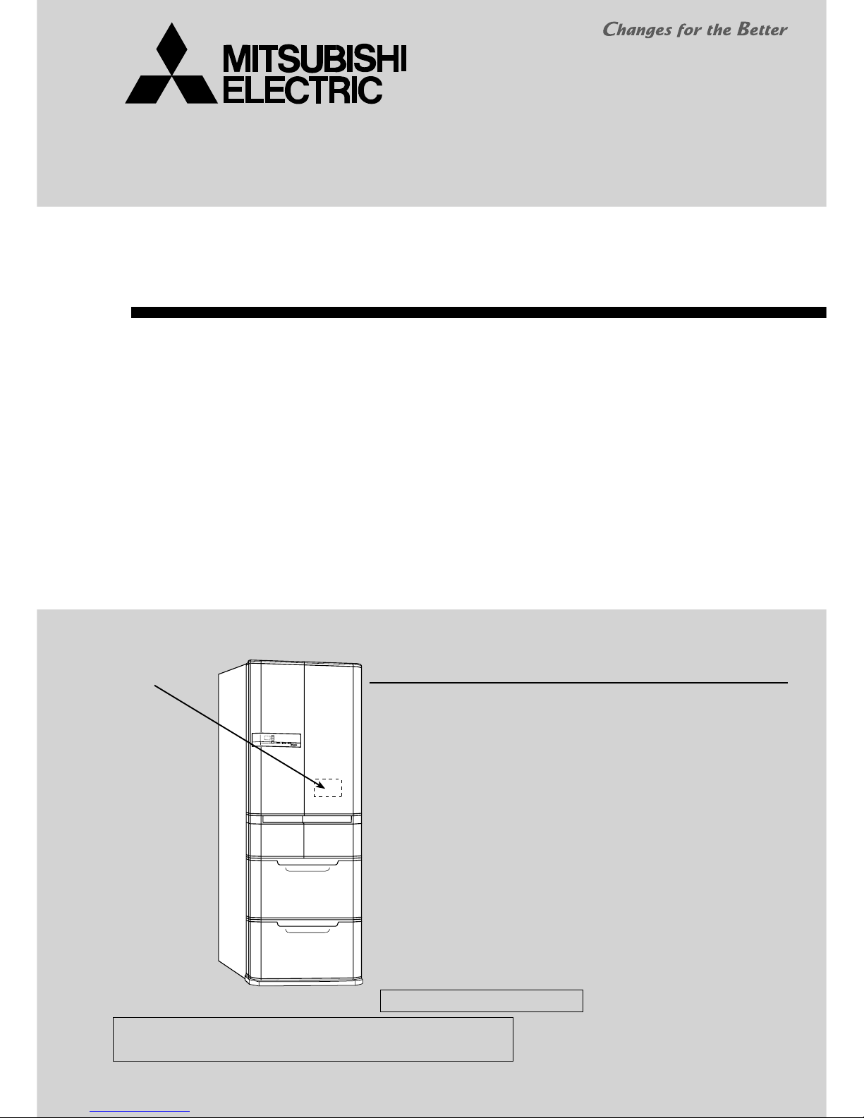
HOME REFRIGERATOR
No. OAH110
NOTE:
• RoHS compliant products have <G> mark on the spec name plate.
C •••• Taiwan
PARTS CATALOG (OAB110)
Model name
indication
(Inside this door)
2
SPECIFICATIONS
1
SPECIFICATIONS
110 V, 60 Hz
E55R E60R
545 (gross) 601 (gross)
1821 × 685 × 728 1821 × 745 × 728
Cabinet, cabinet ceiling
,
sides,
back and front flange
Cabinet, cabinet ceiling, sides, back,
front flange and machine chamber condenser
103 108
109 115
Acrylic resin coated steel
ABS resin
Foamed polyurethane (Cyclopentane)
Foamed polyurethane (Cyclopentane)
Foamed polyurethane (Cyclopentane)
Forced air convection
Forced air convection
Fin and tube type
Automatic heater defrost
Automatic drainage, Forced evaporation method
Automatic control
LED
187 (FREOL S10)
9
kg
kg
mm
g
g
g
V,Hz
L
mm
Unit
Shipping
Weight
Accessories
Evaporator
Condenser
Defrost system
Drain
Temperature control system
Refrigerator compartment interior light
Power supply
Total capacity
Dimensions (H × W × D)
Cabinet
Food liner
Cabinet
Freezer door
Refrigerator door
Freezer
Refrigerator
Insulation
Cooling system
Capillary tube
Desiccant (molecular sieve)
Refrigerant filling capacity R600a
Refrigerating oil (model)
Change pocket (large)
Change pocket (small)
Bottle pocket (large)
Bottle pocket (small)
AUTO-shelf
Two-way flexishelf
Small item case
Free egg shelf
Slide chilled case
Lid of slide chilled case
Versa case
Aluminum tray (Versa case)
Water tank (with light-type bacteria removing filter with lead elimination function)
Freezing case (top)
Freezing case (bottom)
Ice server
Soundproof mat
Ice storage box
Vegetable case
Sliding case (Vegetable case)
Leg cover
2pcs.
2pcs.
1pc.
1pc.
2pcs.
1pc.
1pc.
1pc.
1pc.
1pc.
1pc.
1pc.
1pc.
1pc.
1pc.
1pc.
1pc.
1pc.
1pc.
1pc.
1pc.
1.6 × 0.63 × 2740, 1.8 × 0.67 × 2740
94
MR-E55R-C
MR-E60R-C
3
Temperature control
ON
−22.2
−18.9
−14.3
–
–
–
–
–
–
–
–
–
OFF
−23.8
−20.6
−16.0
–
–
–
–
–
–
–
–
–
OPEN
1.9
5.1
8.4
–
–
–
–
–
–
–
–
–
SHUT
0.1
3.2
6.4
–
–
–
–
–
–
–
–
–
Dial position
HI
MID
LOW
LOW (Soft freezing)
MID (Soft freezing)
HI
(Soft freezing)
FREEZER(LOW)
FREEZER(MID)
FREEZER(HI)
ICE MAKING
ICE MAKING STOP
CRYSTAL ICE MAKING
Model
NTC thermistor
Freezer
Compressor HeaterMotor damper
Refrigerator
OFF
4.2
6.1
7.7
–
–
–
–
–
–
–
–
–
ON
2.9
4.8
6.4
–
–
–
–
–
–
–
–
–
OPEN
–
–
–
−5.9
−9.8
−11.1
−12.0
−16.1
−17.7
–
–
–
SHUT
–
–
–
−7.1
−11.1
−12.3
−15.1
−19.4
−21.2
–
–
–
VegetableVersa
OPEN
–
–
–
–
–
–
–
–
–
−21.6
−21.6
−21.6
SHUT
–
–
–
–
–
–
–
–
–
−23.4
−23.4
−23.4
Ice making
W
A
A
Sec.
A
W
rpm
W
rpm
Compressor
Motor protector
Heater
(Rating)
Freezer
compartment
Refrigerator
Machine
chamber
Fan motor
Defrosting
control
Model
Power supply
Rated input
Starting current
Running current
Winding resistance (A.T.20 )
Model
Ambient temperature
Time
Current
Model
Type
Model
Specification
Defrost finish
Thermal fuse
Defrost heater 1
Defrost heater 2
Deodorizing function of defrost heater
Model
Type
Input
Revolution
Number of poles
Model
Input
Revolution
Number of poles
Water pipe heater
Rotational heater board
Vegetable compartment heater
Ice making tray heater
Water tank heater
EFI100E 13DHH
110 V, 60Hz
45 (1620rpm)
4 (Current limiter)
0.69 (1620rpm)
12.4
MM3-71CCV
25
16 or less
17.0
NSCE001DC1
4-phase stepping motor drive voltage DC12V
141 (110V,86W)
81 (110V,150W)
Control board
Microcomputer
Thermistor 14 ± 1.5
70 ± 2
Not equipped
UDQM002B3
DC brushless motor
2.4 (12V DC)
1520 (12V DC)
10P
4715JL04WS16G51
1.4 (12V DC)
1450 (12V DC)
4P
110V-4.0W
110V-8.0W
110V-7.3W
110V -12.1W
110V-4.0W
Defrosting
timer
Three-way valve
ELECTRICAL PARTS SPECIFICATIONS
MR-E55R-C
4
Temperature control
ON
−21.9
−19.2
−13.7
–
–
–
–
–
–
–
–
–
OFF
−23.5
−20.8
−15.4
–
–
–
–
–
–
–
–
–
OPEN
0.7
3.8
7.0
–
–
–
–
–
–
–
–
–
SHUT
−1.2
1.9
5.1
–
–
–
–
–
–
–
–
–
Dial position
HI
MID
LOW
LOW (Soft freezing)
MID (Soft freezing)
HI
(Soft freezing)
FREEZER (LOW)
FREEZER (MID)
FREEZER (HI)
ICE MAKING
ICE MAKING STOP
CRYSTAL ICE MAKING
Model
NTC thermistor
Freezer
Compressor HeaterMotor damper
Refrigerator
OFF
7.0
9.0
10.7
–
–
–
–
–
–
–
–
–
ON
5.1
7.0
8.7
–
–
–
–
–
–
–
–
–
OPEN
–
–
–
−7.1
−9.5
−10.7
−11.4
−16.5
−18.0
–
–
–
SHUT
–
–
–
−8.3
−10.7
−12.0
−14.5
−19.7
−21.5
–
–
–
VegetableVersa
OPEN
–
–
–
–
–
–
–
–
–
−17.9
−17.9
−17.9
SHUT
–
–
–
–
–
–
–
–
–
−20.8
−20.8
−20.8
Ice making
W
A
A
Sec.
A
W
rpm
W
rpm
Compressor
Motor protector
Heater
(Rating)
Freezer
compartment
Refrigerator
Machine
chamber
Fan motor
Defrosting
control
Model
Power supply
Rated input
Starting current
Running current
Winding resistance (A.T.20 )
Model
Ambient temperature
Time
Current
Model
Type
Model
Specification
Defrost finish
Thermal fuse
Defrost heater 1
Defrost heater 2
Deodorizing function of defrost heater
Model
Type
Input
Revolution
Number of poles
Model
Input
Revolution
Number of poles
Water pipe heater
Rotational heater board
Vegetable compartment heater
Ice making tray heater
Water tank heater
EFI100E 13DHH
110 V, 60Hz
45 (1620rpm)
4 (Current limiter)
0.69 (1620rpm)
12.4
MM3-71CCV
25
16 or less
17.0
NSCE001DC1
4-phase stepping motor drive voltage DC12V
110V-4.0W
110V-12.1W
81Ω (110V, 150W)
141Ω (110V, 86W)
Control board
Microcomputer
Thermistor 14 ± 1.5
70 ± 2
Not equipped
UDQM002B3
DC brushless motor
2.4 (12V DC)
1520 (12V DC)
10P
4715JL04WS16G51
1.4 (12V DC)
1450 (12V DC)
4P
110V-4.0W
110V-8.0W
110V-7.3W
Defrosting
timer
Three-way valve
ELECTRICAL PARTS SPECIFICATIONS
MR-E60R-C
5
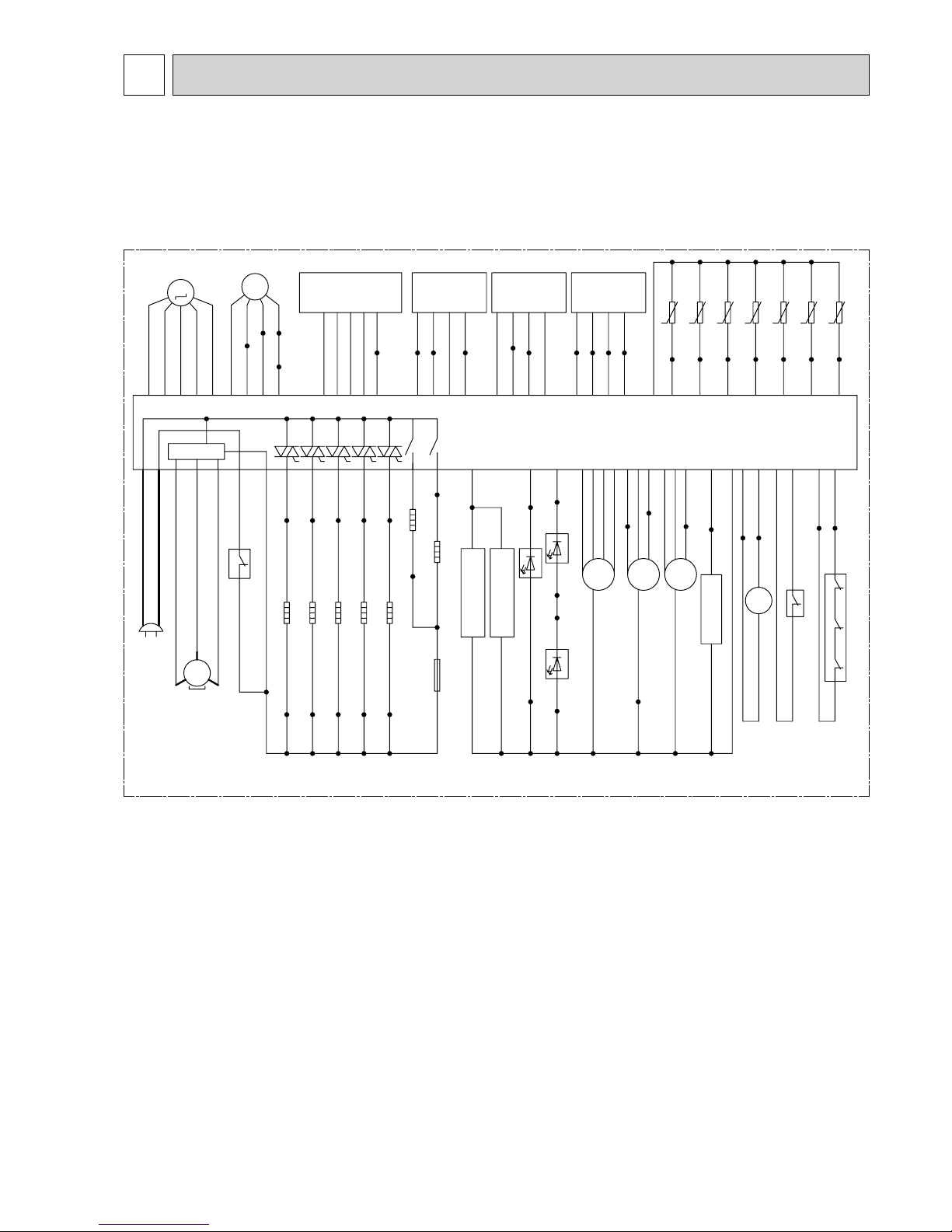
WIRING DIAGRAM
2
( SKELETON WIRING DIAGRAM )
MR-E55R-C
MR-E60R-C
I.THERMISTOR (Ice making compartment thermistor)
V.THERMISTOR (Vegetable compartment thermistor)
VERSA.THERMISTOR (Versa compartment thermistor)
DEF.THERMISTOR (Defrost thermistor)
ICE-TRAY THERMISTOR (Ice making tray thermistor)
F.THERMISTOR (Freezer compartment thermistor)
R.THERMISTOR (Refrigerator compartment thermistor)
TEMP. CONTROL BOARD: (Operation P.C. board)
COMPENSATIONAL HEATER FOR VEGETABLE ROOM: (Vegetable compartment heater)
DIVIDER HEATER: (Rotational heater board)
LED BOARD IN VEGETABLE ROOM: LEDs (Vegetable compartment)
TANK LED: (LED for bacteria removal from water tank)
LED BOARD IN REFRIGERATOR ROOM (R): Interior LED (right)
LED BOARD IN REFRIGERATOR ROOM (L): Interior LED (left)
S.LED: Versa compartment supercool freezing LED
R.LED(D): Refrigerator deodorization LED
DOOR SW. (FOR R-COMPARTMENT & ICE ROOM): Door switch (for refrigerator compartment, ice compartment)
DOOR SW. (FOR F-COMPARTMENT): Door switch (for freezer compartment)
FAN MOTOR (FOR COMPRESSOR): (BOX FAN)
VALVE MOTOR: Three-way valve
MOTOR DAMPER VS: Motor damper (for vegetable/versa compartment)
MOTOR DAMPER RI: Motor damper (for refrigerator/ice making compartment)
The wiring diagram in the dashed line is the
same as the one attached to the products.
Although the following parts are called in different names here,
they are identical with the parts shown in the service manual.
BLACKBLACK
WATER PIPE HEATER
GRAY GRAYGRAY BLUE
GRAY REDBLUEWHITE
THERMAL FUSE(73
°C
)
DEFROST
HEATER 1
BLACK
M
M
GRAY
RED
VIOLET
YELLOW
BLUE
VALVE MOTOR
WATER TANK HEATER
R.LED(D)
BLUEBLACK
S.LED
VIOLET
BLACK
PLUG
F1 : 10A FUSE
FUSE3
:
3A FUSE
ON THE BOARD
CONTROL BOARD,N/F BOARD
INVERTER
*
WHEN THE DOORS ARE CLOSED.
ICE GEAR BOX
(ON DISPLAY PANEL)
TEMP. CONTROL BOARD
MOTOR DAMPERRIMOTOR DAMPER
VS
THERMOPILE
WHITE
RED
YELLOW
SKY BLUE
LIGHT
BROWN
WHITE
WHITE/RED
BLUE
VIOLET
SKY BLUE
BLACK
GRAY
PINK RED
SKY BLUE
WHITE
GRAY
BLACK
BLACK
BLACK
BLACK
BLUE
WHITE
YELLOW
RED
ORANGE
BLUE
WHITE
YELLOW
RED
YELLOW
GREEN
PINK
GRAY
BROWN
SKY BLUE
WHITE/RED
LIGHT
BROWN
ORANGE
BLUE
PINK
BRIGHT
YELLOW
YELLOW
BROWN
WHITE
WHITE
WHITE
WHITE
WHITE
WHITE
WHITE WHITE
WHITE
WHITE
WHITE
WHITE
WHITE
WHITE
R.THERMISTOR
F.THERMISTOR
ICE TRAY THERMISTOR
DEF.THERMISTOR
VERSA THERMISTOR
V.THERMISTOR
I.THERMISTOR
WHITE
BLACK
WHITE
RED
YELLOW
GRAY
WHITE
GRAY
GRAY
GRAY
GRAY
LIGHT
GREEN
YELLOW
WHITE
ORANGE
BLUE
WHITE
GRAY
GRAY
WHITE
BLUE
GRAY
GRAY
WHITE
WHITEWHITE
WHITE
DEFROST
HEATER 2
GRAY
DIVIDER HEATER
COMPENSATIONAL HEATER
FOR VEGETABLE ROOM
ICE TRAY HEATER
MOTOR PROTECTOR
COMPRESSOR
LIGHT
GREEN
BLACKREDVIOLET
WHITE/RED
WHITE/RED
TANK LED
LIGHT BROWN
BRIGHT YELLOW
RED
YELLOWVIOLET
MOVE EYE MOTOR
FAN MOTOR (FOR COMPRESSOR)
FAN MOTOR
LIGHT GREENWHITE
ORANGE
BLACK
BRIGHT YELLOW
YELLOW
BLACK
YELLOW
VIOLET
VIOLET
VIOLET
VIOLET
PINK
RED
LIGHT BROWNWHITE
WATER PUMP
YELLOW GREENWHITE
BROWNRED
DOOR SW.(FOR F-COMPARTMENT)
*
DOOR SW.(FOR R-COMPARTMENT & ICE ROOM)
*
LED BOARD IN
VEGETABLE ROOM
SKY BLUE
SKY BLUE
WHITE/RED
WHITE LIGHT BROWN
LED BOARD IN
REFRIGERATOR ROOM
(L)
WHITE
V
MS
3
˜
W
U
LED BOARD IN
REFRIGERATOR ROOM
(R)
LIGHT
BROWN
RED
LIGHT
GREEN
M
MMM
6
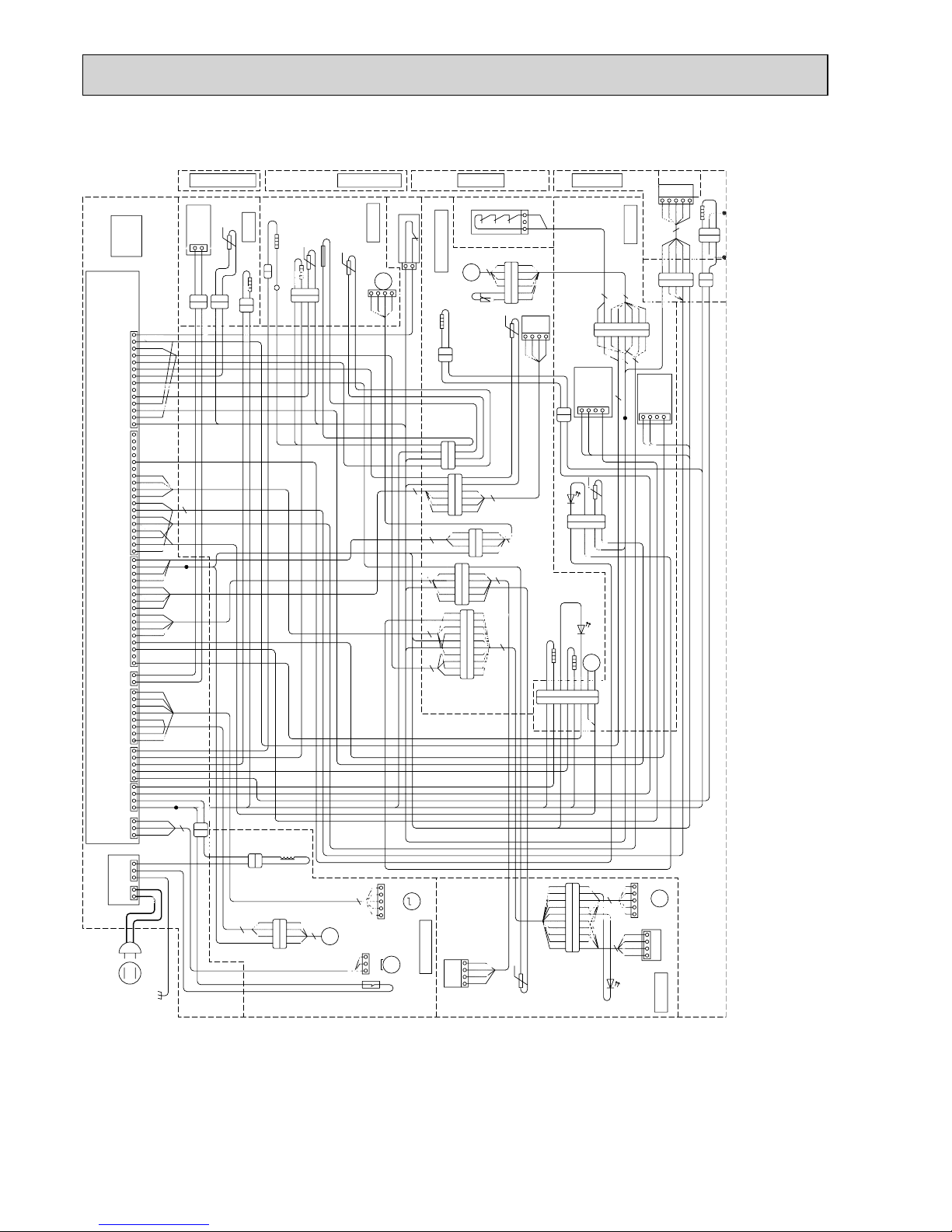
MR-E55R-C
MR-E60R-C
( ACTUAL WIRING DIAGRAM )
( When the doors are closed. )
I.THERMISTOR (Ice making compartment thermistor) V.THERMISTOR (Vegetable compartment thermistor)
VERSA.THERMISTOR (Versa compartment thermistor) DEF.THERMISTOR (Defrost thermistor)
ICE-TRAY THERMISTOR (Ice making tray thermistor) F.THERMISTOR (Freezer compartment thermistor)
R.THERMISTOR (Refrigerator compartment thermistor) TEMP. CONTROL BOARD: (Operation P.C. board)
V.HEATER (Vegetable compartment heater) DIVIDER HEATER: (Rotational heater board)
VEGETABLE LED: LEDs (Vegetable compartment) TANK LED: (LED for bacteria removal from water tank)
R/I ROOM DOOR SWITCH: Door switch (for vegetable compartment, ice compartment)
FREEZER ROOM DOOR SWITCH: Door switch (for freezer compartment)
FAN MOTOR (FOR COMPRESSOR): (BOX FAN) R.LED(R): Interior LED (right)
R.LED(L): Interior LED (left) S.LED: Versa compartment supercool freezing LED
R.LED(D): Refrigerator deodorization LED VALVE MOTOR: Three-way valve
MOVE EYE MOTOR: i-see sensor
3
1
2
AC110V
60Hz
13
26
7
13
5
31
5
7
31
87 54 13
8 5
7
1
24
8
12
3
4
56
8791012 112134576910
5
1112
69
3
5
2
1
9101112131415
14 13
4
3
3
1
221
1
2
1
2
1
3
8765432
1
6
2
3
3
2
3
1
5
5
423
1
1
2
2
1
3421
145623
654321
4321
98 462753110
3
4
4
3
4
654321
4
1
4
4
2
1
2
1
1234567
8
4
4
10
3
4
4
5
3
131415161718
1
2
16
2
1
CN61L
5
31
1
2
4
4
4
3
2
2
GRAY
GRAY
GRAY
GRAY
GRAY
GRAY
GREEN
GREEN
WHITE
WHITE
GRAY
WHITE
RED
RED
PINK
BLACK
BLACK BLACK
SKY BLUE
SKY BLUE SKY BLUE
VAIOLET
VAIOLET
GRAY
VAIOLET
5
1
3
1
t°
t°
t°
t°
t°
t°
t°
TEMP.
CONTROL BOARD
DIVIDER
HEATER
REFRIGERATOR
COMPARTMENT
REFRIGERATOR
COMPARTMENT DOOR
WHITE
WHITE
RED
SKY BLUE
SKY BLUE
SKY BLUE
SKY BLUE
SKY BLUE
LIGHT BROWN
LIGHT GREEN
LIGHT GREEN
LIGHT BROWN
BLUE
BLUE
WHITE
WHITE/ RED
R, LED
(R):
WHITE
WHITE
WHITE/ RED
WHITE/ RED
WHITE/ RED
WHITE/ RED
R, LED
(L):
ICE/ VERSA
COMPARTMENT DOOR
WHITE
WHITE
2
R/ I ROOM
DOOR SWITCH
ICE COMPERTMENT
RED
SKY BLUE
SKY BLUE
LIGHT BROWN
LIGHT GREEN
BLUE
WHITE
WHITE
WHITE
RED
BLUE
YELLOW
M
MOTOR
DAMPER
ICE
GEAR
BOX
ICE TRY
THERMISTOR
ICE TRY HEATER
I. THERMISTOR
RED
BLUE
WHITE
YELLOW
WHITE
WHITE
FREEZR COMPARTMENT DOOR
VEGETABLE COMPRATMENT DOOR
FREEZER ROOM DOOR SWITCH
FREEZR
COMPARTMENT
M
FAN
MOTOR
WHITE/ RED
SKY BLUE
PINK
YELLOW
BRIGHT YELLOW
VAIOLET
THERMAL
FUZE (73ºC)
F. THERMISTOR
DEF. THERMISTOR
DEFROST
HEATER 2
DEFROST HEATER 1
WHITE
WHITE
BLACK
BLACK
PINK
SKY BLUE
BLACK
WHITE
WHITE
WHITE
WHITE
WHITE WHITE
LIGHT BROWN
WHITE
BLUE
RED
VEGETABLE
COMPARTMENT
VEGETABLE
LEDS
BLUE
BLUE
VAIOLET
VAIOLET
VAIOLET
YELLOW
SKY BLUE
ELECTRIC
BOX
CONTROL
BOARD
GRAYGRAY
YELLOWYELLOW
GRAY
YELLOW
R. THERMISTOR
R. LED (D)
WHITE
WHITE
LIGHT GREEN
ORANGE
SKY BLUE
LIGHT GREEN
LIGHT BROWN
LIGHT BROWN
M
WATER PUMP MOTOR
TANK LED
WHITE
RED
RED
BLACK
GRAY GRAY
GRAY
BLUE
VIOLET
ORANGE
GRAY
GRAY
GRAY
WATER PIPE HEATER
YELLOW GREEN
LIGHT GREEN
BROWN
WHITE
GRAY
WHITE
WHITE
WHITE
WHITE
WHITE
WHITE
WHITE
YELLOW
YELLOW
WHITE
RED
RED
RED
BLUE
BLUE
BLUE
WHITE
GRAY
SKY BULE
SKY BULE
ORANGE
BLUE
RED
WHITE/ RED
YELLOW
VIOLET
PINK
BRIGHT YELLOW
YELLOW
VIOLET
BLACK
BRIGHT YELLOW
BRIGHT YELLOW
BRIGHT YELLOWBRIGHT YELLOW
LIGHT GREENYELLOW GREEN
LIGHT BROWN
WHITE
LIGHT BROWN
WHITE
YELLOW GREEN
GRAY
SKY BULE
PINK
BROWN
SKY BULESKY BULE
VIOLETVIOLET
YELLOWYELLOW
GRAYGRAY
RED
BLACK
RED
BLACK
FILTER BOARD
WHITE/ RED
LIGHT BROWN
WHITE
BLACK
BLUE
RED
YELLOW
YELLOW
YELLOW
YELLOW
YELLOW
YELLOW
BRIGHT YELLOW
LIGHT GREEN
PINK
PINK
PINK
ORANGE
ORANGE
ORANGE
ORANGE
GRAY
GRAY
GRAY
GRAY
GRAY
SKY BULE
LIGHT BROWN
BROWN
BROWN
LIGHT BROWN
BRIGHT YELLOW
RED
RED
RED
RED
RED
WHITE
WHITE/ RED
WHITE/ RED
BLUE
BLUE
BLUE
BLUE
YELLOW GREEN
YELLOW GREEN
BRIGHT YELLOW
BLACK
BLACK
BLACK
BLACK
BLACK
BLACK
BLACK
VIOLET
VIOLET
VIOLET
VIOLET VIOLET
WHITE
WHITE
WHITE
WHITE
WHITE
WHITE
LIGHT GREEN
LIGHT GREEN
LIGHT GREEN
LIGHT BROWN
BLACK
WHITE
WHITE
BLACK
WHITE
WHITE
REACTOR
2
1
43
YELLOWORANGE
BLACK BLACK
VIOLET
LIGHT GREEN WHITE
RED
M
M
MS
3
˜
M
YELLOW
VIOLET
GRAY
RED
BLUE
25413
VALVE MOTOR
COMPRESSOR
(VIEW FROM REAR LEFT SIDE)
MACHINE CHAMBER
COMPARTMENT
213
WHITE
BLACK
RED
FAN MOTOR
(COMPRESSOR)
MOTOR
PROTECTOR
4
1
YELLOW
RED
BLUE
WHITE
MOTOR
DAMPER
VERSA
THERMISTOR
7
1
248563910
1
2453
2
3
LIGHT BROWN
LIGHT GREEN
LIGHT BROWN
LIGHT BROWN
BRIGHT YELLOW
BRIGHT
YELLOW
BRIGHT YELLOW
WHITE
SKY BLUE
YELLOW
YELLOW
YELLOW
GRAY
BLACK
RED
RED
BLACK
BLACK
BLACK
BLACK
BLACK
VIOLET /BLACKVIOLET
VIOLET
RED
BLACK
BLACK
BLACK
BLACK
4
1
2
3
VERSA
COMPARTMENT
THERMOPILE
MOVE EYE MOTOR
S.LED
TANK HEATER
432
1
V. HEATE R
LIGHT GREEN
GRAY
V. THERMISTOR
1
2
VIOLET
7
393
245
309
300
96
547
541
666(
Pitch between the front wheels
)
631(
Pitch between the adjust bolts
)
578(
Pitch between the rear wheels
)
363
8
363
8
128
8
5.5
2500
407
363
394.5
6
283.5
363 212 822
394.5283.5
6
1821
(Display)
685(Display)
680(Cabinet)
77
318
400
408
436
337
249
595
595
595
196
203
307
541
581
539
596
655
37
728(Display)
142
179
101
760
53
633
10
331
37
333
175
41
1075
204
314
86
104
358.5
358.8
348
255
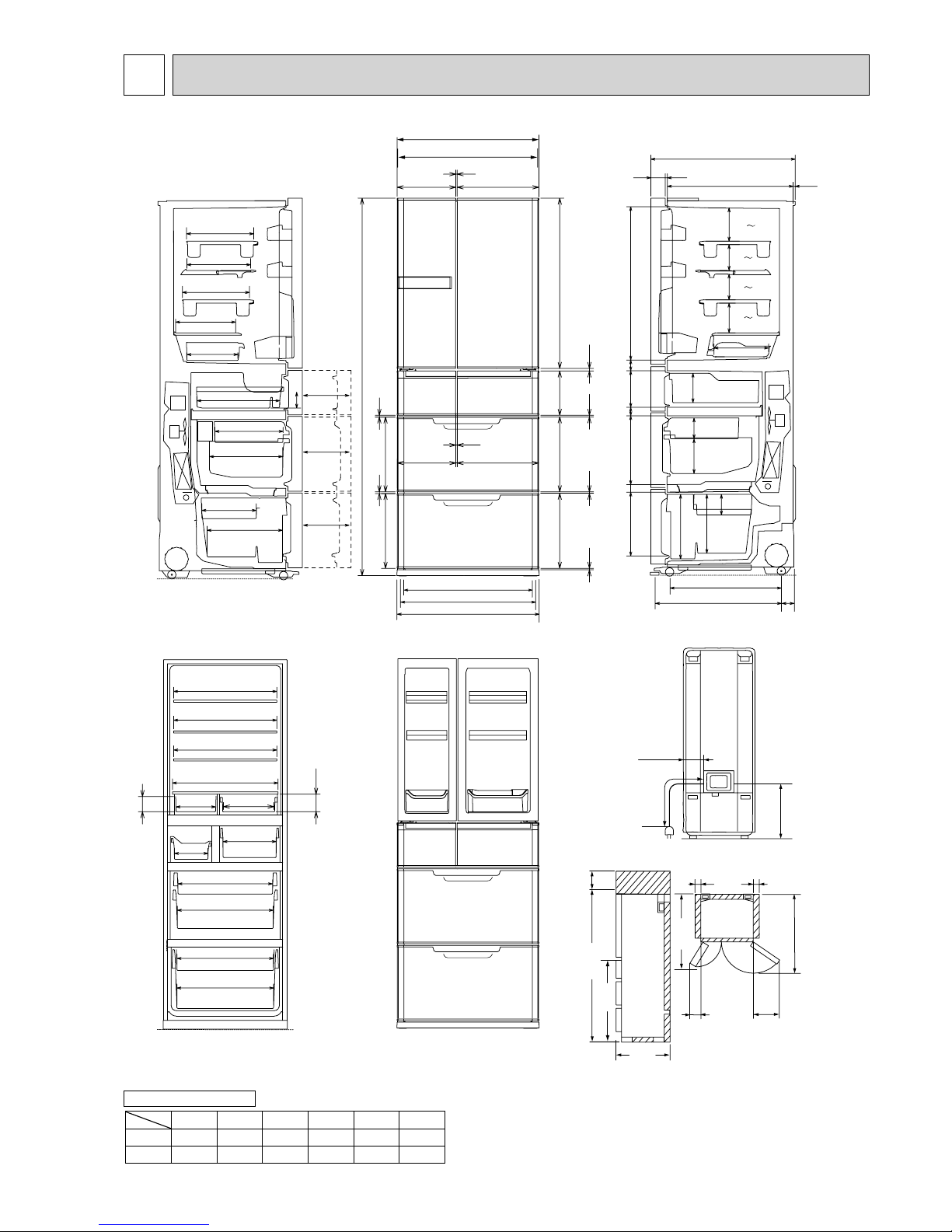
REQUIRED SPACE FOR INSTALLATION
1821
20 685 20
211
290
950
728
100
1061
989
180.5
222
125
83.5
125
83.5
159.5
201
406
413
OUTLINES AND DIMENSIONS
3
MR-E55R-C
Unit : mm
R(L) : Refrigerator compartment (Left)
R(R) : Refrigerator compartment (Right)
I : Ice making compartment
S : Select compartment [Versa compartment]
F : Freezer compartment
V : Vegetable compartment
R(L) R(R) I S F V
Hight 822 822 212 212 363 363
Width 283.5 394.5 283.5 394.5 684 684
DOOR DIMENSION
8
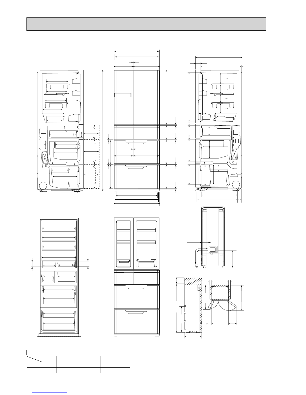
MR-E60R-C
393
245
309
300
96
607
601
REQUIRED SPACE FOR INSTALLATION
726(
Pitch between the front wheels
)
691(
Pitch between the adjust bolts
)
638(
Pitch between the rear wheels
)
363
8
363
8
12
8
8
5.5
2500
407
363
454.5
6
283.5
363 212 822
454.5283.5
6
1821
(Display)
745(Display)
740(Cabinet)
77
318
400
408
436
337
249
655
655
655
196
203
367
601
641
599
596
655
37
728(Display)
142
179
101
760
53
633
10
331
37
333
175
41
1075
204
374
86
104
358.5
358.5
348
255
1821
20 745 20
211
335
950
728
100
1121
180.5
222
125
83.5
125
83.5
159.5
201
989
406
413
R(L) : Refrigerator compartment (Left)
R(R) : Refrigerator compartment (Right)
I : Ice making compartment
S : Select compartment [Versa compartment]
F : Freezer compartment
V : Vegetable compartment
R(L) R(R) I S F V
Hight 822 822 212 212 363 363
Width 283.5 454.4 283.5 454.5 744 744
DOOR DIMENSION
9
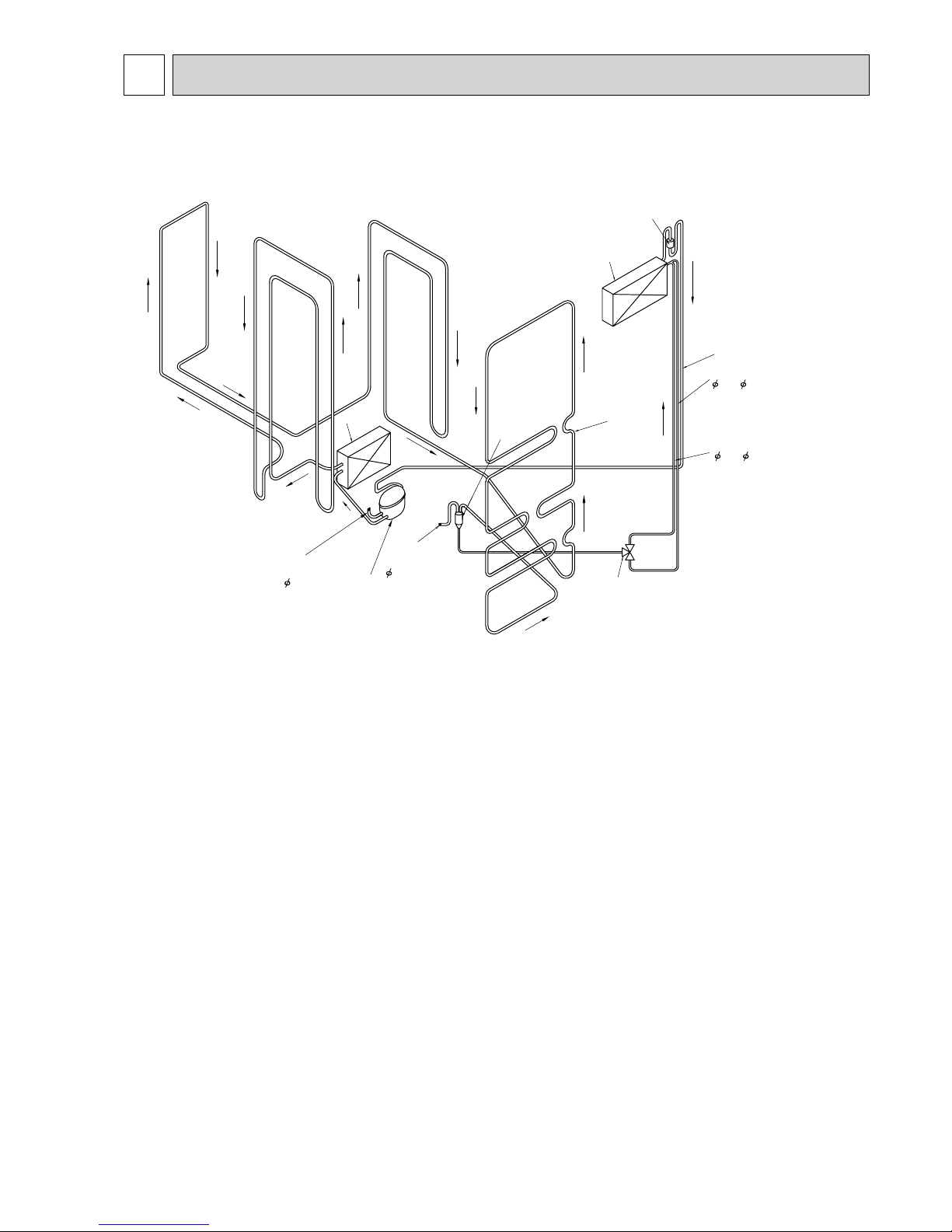
REFRIGERANT CIRCUIT
4
Capillary tube
1.8× 0.67×2740 (mm)
1.6× 0.63×2740(mm)
Suction pipe
Muffler
Evaporator
Dryer
Cabinet
pipe
#150
Compressor
Charge pipe
(Low pressure
side) 6.35
Charge pipe
(High pressure side)
Condenser
Capillary tube
Three-way
valve
4.0
MR-E55R-C
MR-E60R-C
10
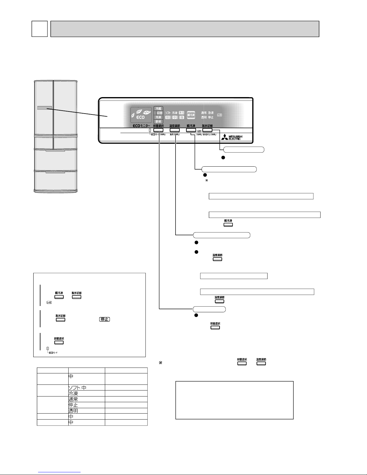
ROOM button
Pressing this button selects the
compartment to be displayed.
Press to select the compartment before adjusting
the temperature or cooling fast.
When the versa compartment is set at soft freezing
mode, fast cooling cannot be selected.
SELECT / QUICK button
Pressing this button sets each compartment’s temperature.
In order to cool fast:
QUICK mode stops automatically
• QUICK mode automatically stops in 2 hours.
When stopping QUICK mode before it automatically ends
Press for 3 seconds.
This operation starts only when the room selection is set to
the versa compartment, and also the versa compartment is
set to soft freezing mode.
• Press once.
The supercool freezing operation ends automatically
• The superc ool freezing operation automatically ends
after 6 to 8 hours.
When stopping the supercool freezing operation before it automatically ends
• Press once.
ICE SELECT button
Supercool freezing button
Pressing this button selects the setting
of the ice making compartment.
The supercool freezing operation starts.
To reset the settings when initialled, press and simultaneously
for 3 seconds. The temperatures of the refrigerator, vegetable, and freezer compartments
will be set to “Middle” .The Fast Cooling operations in all the compartments will stop.
USEFUL FUNCTIONS
Press and simultaneously for 3 seconds.
Child lock
( lamp turns on)
1
2
Press several times until is displayed.
Stop ice making
3
Press button for 3 seconds.
( lamp turns on)
ECO mode (To start and cancel)
Operating mode and Temperature range
Compartment
Mode
Temp. range
Approx.
0 to 6
°C
Approx.
−9 to −5°C
Approx.
−
18 to −12
°C
Approx.
−
21 to −17
°C
Approx.
−
21 to −17
°C
Approx.
−21 to −17°C
Approx.
3 to 9°C
Approx.
−21 to −17°C
Refrigerator
compartment
Versa
compartment
Ice making
compartment
Vegetable compartment
Freezer compartment
The temp. range is based on the data measured at the center of each compartment with the door closed and with no
food inside under the condition of ambient temperature 30°C.
TROUBLESHOOTING
5
MR-E55R-C
MR-E60R-C
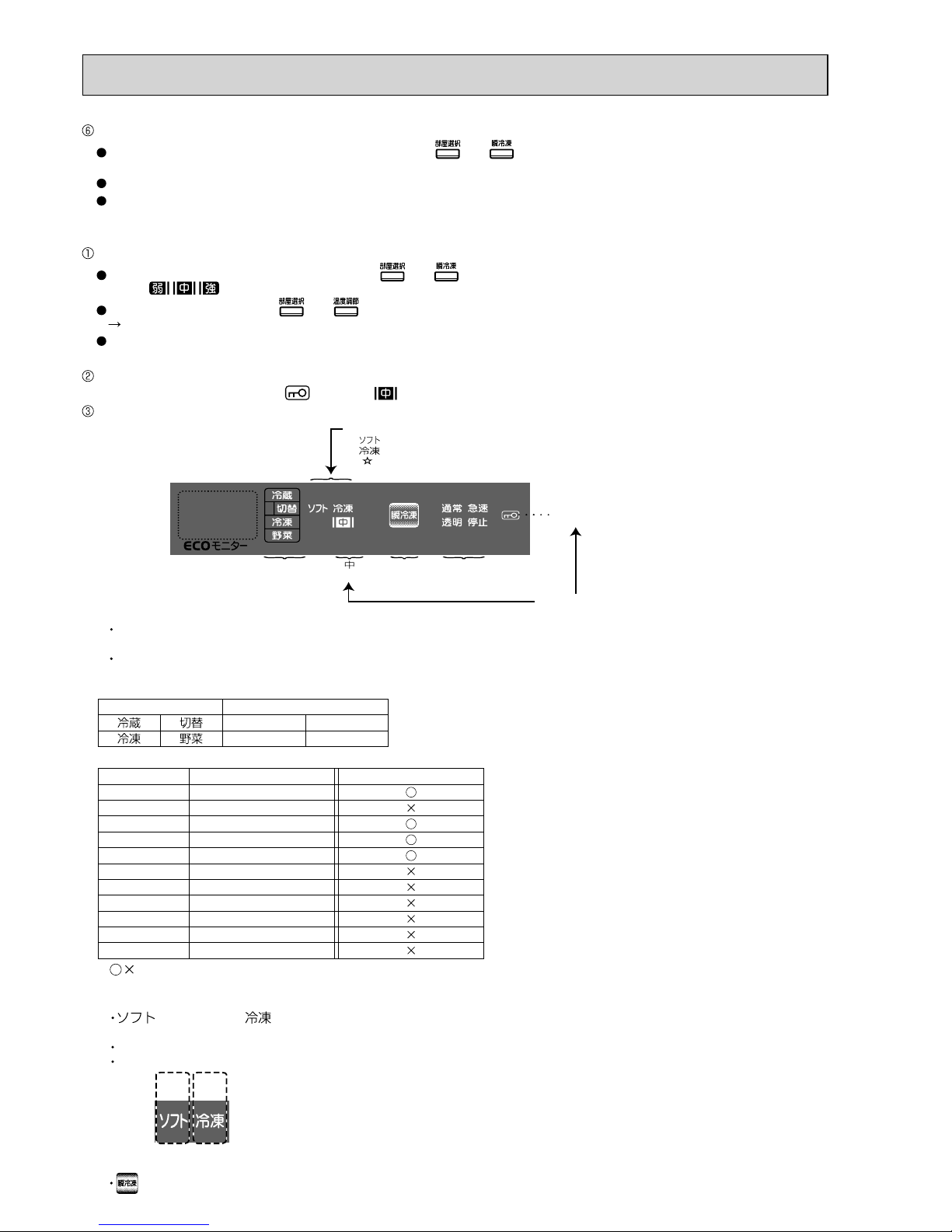
(1) Function of normal operation
5-1 FUNCTION OF OPERATION PANEL
· The display extinguishes in 30 seconds
after the last button is pressed.
(No failure in refrigerator)
· Pushing any button turns on the display
again.

11
(2) Demonstration mode for shop display
Setting
Within 1 minute after power supply turns on, press the , , and simultaneously for 5 seconds
with the door of the ice making compartment opened.
When the setting is complete, a “beep” sound is heard and “Auto Demo Mode” is displayed.
Demonstration mode is not available when the temperature of freezer compartment is –7°C or lower.
Panel operation mode during demonstration mode
The panel operation mode changes to “manual” if any of the switches is pressed. It changes to "auto" if none of the switches
is pressed for 45 seconds since the last time any of the switches was pressed.
Manual mode: Panel indication changes according to switch operation.
Auto mode: Panel indication is automatically changed.
Release
1) Open the ice making compartment’s door during demonstration mode, and leave it open.
2) Press
button twice.
3) Simultaneously press
, , and for 5 seconds. (A “beep” sound is heard in about 5 seconds.)
Verify that the room display and the temperature adjustment display on the operation panel do not light by turns a minute
after the 3 steps above are performed.
Note: Follow the procedure above to release demonstration mode as it cannot be released by simply turning
on/off the power supply.
(3) Fine adjustment of temperature
Fine adjustment of temperature is available for refrigerator compartment, freezer compartment and versa
compartment.
As for versa compartment, however, it is only available when the compartment is set to
.
Setting
Simultaneously press and for about 3 seconds until a “beep” sound is heard.
Room display blinks every 10 seconds in fine adjustment mode.
Fine adjustments of temperature
Follow the same operation procedure for temperature adjustment.
Release
Follow the same procedure as Setting and the finely-adjusted
temperatures are reset for refrigerator compartment, freezer
compartment and versa compartment at once.
Temperature is adjusted in approximately 0.3 to 0.6°C
increments.
(4) Ice making test/Self-check
Setting
Press for about 5 seconds.
Operation and its display
While automatic ice making is testing, the indication of ice
making compartment setting blinks on display.
When something is faulty, the error code is indicated.
Release
The test automatically finishes in 10 minutes.
Fine adjustment of temperature
Normal mode
Fine adjustment mode
Note: -25 °C freezing.
Select the maximum setting of the
temperature adjustment function for the
freezer compartment.
There is no particular display when the
setting is selected.
(5)
“LOW” setting on the anti-condensation heater
Outline
This setting lowers energy on the anti-condensation heater,
allowing for lower power consumption.
If, however, the condensation forms on the partitions, cancel
the setting.
Setting
Press and buttons simultaneously for 3 seconds
(until 1 beep sound is heard ).
Cancellation
Go through the same procedure as that of Setting (2 beep
sounds are heard when cancelled).
When the settings are reset, this setting is also cancelled.
Display/indication of the setting status
No display is available to show the low setting state on the
anti-condensation heater.
The number of beep sounds indicates the setting state.
Beep (1 time) Set to Low
Beep beep (2 times)
Low setting is canceled and returned to normal state.
12
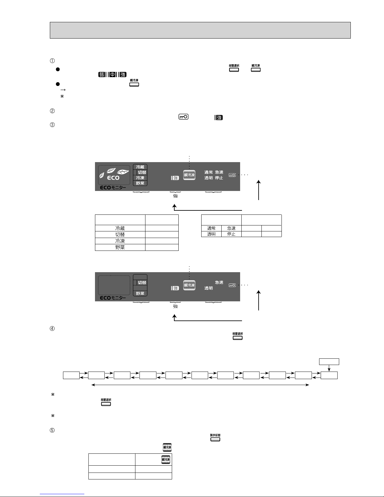
(6) Service Check Function
1) Outline
• The chart below shows the outline of service check function.
• “Service check entry” needs to be set in order to perform each check mode. After setting “service check entry,” start the
setting operation of the check mode to be displayed.
• blinks while service check function is performed.
• The display of
indicates which mode is in operation.
• When one of the check modes is in operation, other modes cannot be set. The mode in operation needs to be cancelled
before setting another mode.
Once each check mode starts, it continues operating even if the door gets closed.
(Open the door when releasing each mode.)
Refer to the next sections about the operation procedure and display of each check mode.
• In order to release “service check function entry,” follow the same procedure as setting operation during “service check
function entry” or each check mode.
Setting / releasing method Display
Door Button operation Blinking
(1)
(2)
(3)
(4)
(4)(1)
(4)(2)
(5)
Open the
ice making com-
partment’s door
Leave the
ice making
compartment’s
door open
Leave the
ice making
compartment’s
door open
Leave the
ice making
compartment’s
door open
Leave the
ice making
compartment’s
door open
Leave the
ice making
compartment’s
door open
Simultaneously press
and for 3 seconds
Simultaneously press
and for
3 seconds
Simultaneously press
and for
3 seconds
Simultaneously press
and for
3 seconds
Press
Press
Press for
3 seconds
Press for
3 seconds
DisplaySetting method
Mode
Door Button operation Lighting
Blinking
1) Compressor’s rotational speed change mode
…The rotational speed of the compressor can be
changed; The fan motor in machine chamber
can be switched on and off.
2) Damper Operation mode
…Each damper can be opened and closed; Refrigerator
fan can be switched on/off.
3) Thermistor temperature check mode
…The detected temperature of each thermistor can
be checked.
4) Error history display mode
…The error occurred in the past can be checked.
(1) History display mode
…All the errors occurred in the past can be
checked in numeric order.
-
(2) Order of occurrence mode
…The newest 5 errors (at the maximum) are
displayed from the newest to the older.
-
5) Set temperature adjustment mode
…The set temperature in each compartment can be
adjusted.
Service check function entry
“History display mode” and “Order of occurrence mode” are
switched over each time is pressed.
13
e.g.) Compressor’s rotational speed 56rps, Fan box fan ON
Blinking
“ ”
Lighting
Fan in box fan ON/OFF
Compressor’s
rotational speed
Tens’ place
Compressor’s
rotational speed
Ones’ place
Display during Compressor’s
rotational speed change mode
Room display
Corresponding
values
8
4
2
1
Ice making mode
display
Corresponding
values
84
21
Blinking
“ ”
Lighting
Fan in box fan ON
Tens’ place "5"
(=4+1)
Ones’ place "6"
(=4+2)
Display during Compressor’ s
rotational speed change mode
Changing the rotational speed
After setting this mode, compressor’s rotational speed changes every time button is pressed.
Rotational speed (rps) is divided into ones’ place and tens’ place when it is displayed.
(Basically the compressor starts operation at level 10, however, it may be different depending on models, or as a result of
specification change.)
<Change of rotational speed>
Rotational speed can be changed only when the compressor is in operation. While the compressor stops, rotational speed is
not displayed, and
button operation is not effective. When the compressor stops, unplug the power code, and wait for
a several minutes, then plug it again.
Operation sound may get increase in the process of changing rotational speed, but that is not dysfunction. Check the sound
level when rotational speed is stabilized.
Switching ON/OFF the box fan
In this mode, box fan can be switched on and off at each press of .
Box fan
The ON/OFF state is displayed with on the display panel.
ON
OFF
Display of
Lighting
Not lighting
2) Compressor’s rotational speed change mode
Setting
With the ice making compartment’s door opened, simultaneously press and for 3 seconds until a “beep”
sound is heard. starts to blink.
With the door opened, press for 3 seconds to start compressor’s rotational speed change mode.
Once this mode starts, it continues operating even if the door is closed.
Compressor’s rotational speed change mode is not available during demonstration mode, thermistor temperature check
mode, set temperature adjustment mode, error history display mode, or when child lock is effective.
Display during compressor’s rotational speed change mode
During compressor’s rotational speed change mode, blinks and lights up.
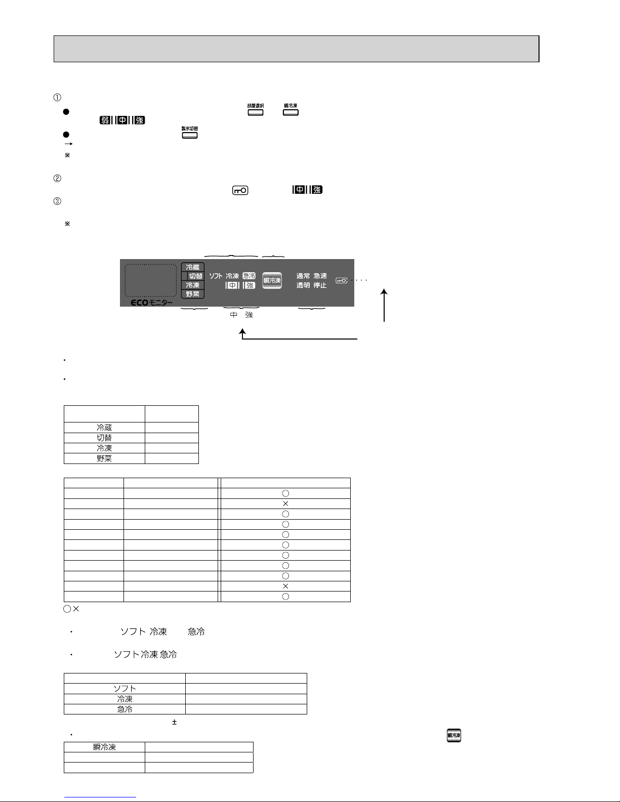
Display of rotational speed
• Compressor’s rotational speed is divided into ones’ place and tens’ place when it is displayed.
• One of the values (8/4/2/1) is assigned to each indicator of both tens’ place and one’ place on the display panel. The sum of
the corresponding values of the lighting indicators is the compressor’s rotational speed.
Level 0 Level 1 Level 2 Level 3 Level 4 Level 5
Normal
Low speed
High speed
Level 6 Level 7 Level 8 Level 9
Level 10
14
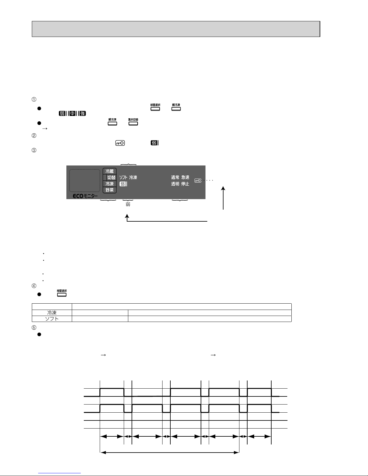
3) Damper Operation Mode
Setting
With the ice compartment door opened, press and simultaneously for 3 seconds until a “beep” sound is
heard. blinks.
With the door opened, press and simultaneously for 3 seconds until a “beep” sound is heard.
Damper operation mode starts. Once this mode starts, it continues operating even if the door gets closed.
Damper operation mode is not available during demonstration mode, thermistor temperature check mode, compressor’s
rotational speed change mode, temperature adjustment mode, error history display mode, or when child lock is effective.
Display during damper operation mode
During damper operation mode, blinks and lights up.
Control state display of each damper
Blinking
“ ”
Lighting
a) Damper
serial number
b) State of damper
: present state
: next state
( The damper of the selected compartment is in operation, the indicator
in the present state blinks.)
During damper operation mode
c) Refrigerator
fan ON/OFF
d) Display during damper
operation “Blinks”
a) Damper serial number
The room display on the display panel corresponds to the values representing damper types. The room display indicators
and their corresponding values (8/4/2/1) are shown in the tables below.
Each serial number is assigned to each compartment (thermistor), which is used in thermistor temperature mode and
set temperature adjustment mode besides damper operation mode. The sum of the corresponding values of the lighting
indicators is the damper’s serial number.
Room Display Corresponding values
84
21
Serial number Assigned compartment Damper operation mode
1 Refrigerator compartment
2 Slide chilled compartment
3 Ice making compartment
4 Versa compartment
5 Vegetable compartment
6 Freezer compartment
7 Defrosting
8 Ice tray
9 Outdoor air
10 Deodorization
11 Thermopile
/ : SW operation is effective/ineffective
b) State of damper
on the left and on the right represent respectively the present state and the next state of the damper
operation.
When the right and left indicators are ON, it indicates that the damper is open.
When the right and left indicators are OFF, it indicates that the damper is close.
c) ON/OFF state of refrigerator fan motor
indicates the ON/OFF state of refrigerator fan motor.
Next
Present
Release
With the ice making compartment’s door opened, press and simultaneously for 3 seconds until a “beep”
sound is heard. The screen returns to the normal temperature display.
The function is automatically released in one hour.
Although unplugging and plugging the power code can release this function, it is recommended to follow the procedure
above for protection of the compressor.
15
Opening and closing dampers
(1) Press to select the damper to be set. Each press of the button makes a “beep” sound and changes the kind of
dampers. The serial number described in a) indicates the selected damper.
The selected damper is displayed using the serial number (1: refrigerator ~ 10: deodorization) in numeric order repeatedly.
Refrigerator damper slide chilled compartment damper ice making compartment damper outdoor air deodorization damper
Slide chilled compartment, defrosting, ice tray, outdoor air, and deodorization can be selected;
however, it is ineffective in damper operation mode.
(2) To open the damper, turn on , and to close the damper, turn off by pressing
button.
Damper operation indicators
on the left and on the right represent respectively the present state and the next state of the damper operation.
The on and off of the right and left indicators indicate respectively the opening and closing of the damper.
The damper operation of the indicator blinking in the “present state” is in operation.
When any of the damper operations including those not selected is in operation, blinks.
Next
Present
Switching ON/OFF the refrigerator fan motor in the unit
In this mode, each press of switches on and off the refrigerator fan motor.
The ON/OFF state of the refrigerator fan motor is represented with .
display Fan motor in the unit
Lighting ON
Not lighting OFF
Release
With the ice making compartment’s door opened, press and simultaneously for 3 seconds until a “beep” sound is
heard. The screen returns to the normal temperature display.
The function is automatically released in one hour.
Although unplugging and plugging the power code can release this function, it is recommended to follow the procedure
above for protection of the compressor.
“ ”
Lighting
a) Serial
number
“3” : Ice making
compartment
b) State of damper
Present: “ ”
Next: “ ”
c) Refrigerator fan
Lighting: ON
Blinking
(3) Press
for 3 seconds to operate the damper. (A “beep” sound is heard when the setting has been conveyed.)
Setting of the operating damper cannot be changed.
Damper operation stops automatically. (Blinking changes to lighting.)
e.g.) When changing the damper of ice making compartment from “CLOSE” state to “OPEN” state, select the indicators as
shown below and press
for 3 seconds.
The present and next damper operations of the selected
compartment illuminate.
When the damper of the selected compartment is in
operation, the indicator in the present state blinks.
<Present and next states of the damper of the selected
compartment>
< The damper of any compartment is in operation>
}
}
16
4) Thermistor temperature check mode
Setting
With the ice compartment door opened, press and simultaneously for 3 seconds until a “beep” sound is
heard. blinks.
With the door opened, press for 3 seconds.
Thermistor temperature check mode starts. Once this mode starts, it continues operating even if the door gets closed.
Thermistor temperature check mode is not available during demonstration mode, compressor's rotational speed change
mode, set temperature adjustment mode, error history display mode, or when child lock is effective.
Display during thermistor temperature check mode
During thermistor temperature check mode, blinks and lights up.
Displaying the thermistor temperature
The kind and temperature of thermistor is displayed on the operation panel.
The ambient temperature detected by thermistor may be a little different from the actual one due to the influence of the
temperature in the refrigerator.
a) Thermistor serial number
The room display on the display panel corresponds to the values representing thermistor types. The room display indicators
and their corresponding values (8/4/2/1) are shown in the tables below.
Each serial number is assigned to each compartment (thermistor), which is used in damper operation mode and
set temperature adjustment mode besides thermistor temperature mode. The sum of the corresponding values of the
lighting indicators is the thermistor’s serial number.
Room display
Corresponding
values
8
4
2
1
Serial number Assigned compartment Thermistor temperature check mode
1 Refrigerator compartment
2 Slide chilled compartment
3 Ice making compartment
4 Versa compartment
5 Vegetable compartment
6 Freezer compartment
7 Defrosting
8 Ice tray
9 Outdoor air
10 Deodorization
11 Thermopile
/ : SW operation is effective/ineffective
b) Thermistor temperature tens’ place
Usually, the , , and indicators that are used for temprature adjustment in the versa compartment represent
tens' place of the thermistor temprature.
Display of
// corresponds to the values, 4/2/1. The sum of the corresponding values of the blinking
indicators is the tens’ place of thermistor temperature.
Room display Corresponding values
4
2
1
c) Thermistor temperature signs
Plus and minus signs of thermistor temperature are indicated on the display which is usually used for mode.
Thermistor temperature signs
Lighting
-
Not lighting +
a) Thermistor
Serial number
b) Thermistor temperature
tens’ place
c) Thermistor temperature
± signs
d) Thermistor
temperature
ones’ place
“ ” “ ”
Lighting
Blinking
Display during
thermistor temperature
check mode
17
d) Thermistor temperature ones’ place
Ones’ place of thermistor temperature is indicated on the display part which is usually used for ice making setting.
Display of
/ / / corresponds to the values, 8/4/2/1. The sum of the corresponding values of lighting
indicators is the ones’ place of thermistor temperature.
Room display
Corresponding
values
8
4
2
1
e.g.) When freezer compartment thermistor is –25 ºC.
“ ” “ ”
Lighting
Blinking
Display during
thermistor temperature
check mode
a) Serial number
“6” : Freezer
b) Tens’ place
“2”
c) Sign
“-”
d) Ones’ place
“5” (=4+1)
Changing the thermistor on display
While thermistor temperature is on display, press .
Each press of the button makes a “beep” sound and changes the kind of thermistor.
Each thermistor is displayed using the serial numbers described in a) in numeric order repeatedly (1: refrigerator
compartment ~ 11: thermopile).
Refrigerator compartment slide chilled compartment ice making compartment versa compartment vegetable
compartment
freezer compartment defrosting ice tray outdoor air deodorization thermopile
When this mode is set, the display always starts from the refrigerator thermistor.
Slide chilled compartment thermistor can be selected; however, it is ineffective because slide chilled compartment thermistor
is not installed.
Deodorization can be selected; however, it is ineffective in thermistor temperature check mode.
Release
With the ice making compartment’s door opened, press and simultaneously for 3 seconds until a “beep”
sound is heard. The screen returns to the normal temperature display.
The function is automatically released in one hour.
Although unplugging and plugging the power code can release this function, it is recommended to follow the procedure
above for protection of the compressor.
18
5) Error history display mode
The errors occurred in the past can be observed as an error history. Use this mode when the actual problem of
the refrigerator is different from the error that was displayed at the service-call received.
Error history display mode offers two ways of display. One of the two is “history display mode,” which shows all
errors occurred in the past in numeric order of the error code; the other is “order of occurrence mode,” which
shows the newest 5 errors (at the maximum) from the newest to the older.
Error history display mode starts with “history display mode.”
Setting
With the ice compartment’s door opened, press and simultaneously for 3 seconds until a “beep” sound is
heard. blinks.
With the door opened, press
and simultaneously for 3 seconds until a “beep” sound is heard.
History error mode starts. Once this mode starts, it continues operating even if a door gets opened.
Display during error history display mode
During error history display mode, blinks and lights up.
Display of error history information.
a)
Mode display
b) Error code
Tens’ place
c) Error code
Ones’ place
“ ”
Lighting
Display during error
history display mode
Blinking
a) Mode display
Display the selected mode between “history display mode” and “order of occurrence mode.”
b) Error code tens’ place
It displays the tens’ place of error code.
It applies the same representative method as the error display of self-check.
c) Error code ones’ place
It displays the ones’ place of error code.
It applies the same representative method as the error display of self-check.
Switching over the mode
Press to select one of the error history display modes. Each press of the button makes a “beep” sound and
switches over between “history display mode” and “order of occurrence mode.”
Compartment Error history display mode
History display mode Display all errors occurred in the past in numeric order of the error code
Order of occurrence mode Display the newest 5 errors (at the maximum) from the newest to the older.
Tens’ place
Ones’ place
Error code
Pre-display
3sec.
0.5
sec.
Repetition
0.5
sec.
0.5
sec.
0.5
sec.
5sec. 5sec. 5sec.
E01 E13 E31
3sec.
Pre-display
Display method
Display method of the error code is the same as self check error display. (Refer to 5-2(3)); however, all indicators used for
the display of error code light up simultaneously for 3 seconds before the first error code is displayed (“pre-display”).
e.g.) When errors occurred in the following order:
fan motor error (E31) communication error of operation panel (E01) refrigerator thermistor error (E13)
• Display during history display mode
Errors are displayed in numeric order.
19
•Display during order of occurrence mode
Errors are displayed from the newest to the older.
Tens’ place
Ones’ place
Error code
Pre-display E13 E01 E31
3sec.
0.5
sec.
Repetition
0.5
sec.
0.5
sec.
0.5
sec.
5sec. 5sec. 5sec. 3sec.
Pre-display
When no error occurred in the past, error code is not displayed.
Check points and resetting the error history
Check and take appropriate measures according to the procedures as stated in 5-2(1).
Conduct self-check again to confirm there is no malfunction. (Make sure all connectors are connected properly and there is
no loose connection.)
Refer to “ Setting” above and activate the error history mode again. With the ice making compartment’s door opend,
press
for 3 seconds to reset error history. (Resetting the error history is completed.) If it is completed correctly,
no error code would be displayed.
Release
With the ice making compartment’s door opened, press and simultaneously for 3 seconds until a “beep”
sound is heard. The screen returns to the normal temperature display.
The function is automatically released in one hour.
Although unplugging and plugging the power code can release this function, it is recommended to follow the procedure
above for protection of the compressor.
a) Compartment
serial number
b) Set temperature
adjustment level
“ ” “ ”
Lighting
Display during set
temperature
adjustment mode
Blinking
6) Set temperature adjustment mode
Switch operation on the operation panel changes the set temperature in each compartment.
Setting
With the ice compartment door opened, press and simultaneously for 3 seconds until a “beep” sound is heard.
blinks.
With the door opened, press
and simultaneously for 3 seconds until a “beep” sound is heard.
Set temperature adjustment mode starts. Once this mode starts, it continues operating even if the door gets closed.
Display during set temperature adjustment mode
During set temperature adjustment mode, blinks and lights up.
Control state display of each compartment

20
a) Compartment serial number
Serial number of the selected compartment for set temperature adjustment is displayed on the part that are usually used
for room display.
Each serial number is assigned to each compartment that will be used in set temperature adjustment mode besides damper
operation mode and thermistor temperature check mode.
The sum of the corresponding values of the lighting indicators is the compartment serial number.
Room display
Corresponding
values
8
4
2
1
Serial number Assigned compartment Set temperature adjustment mode
1 Refrigerator compartment
2 Slide chilled compartment
3 Ice making compartment
4 Versa compartment
5 Vegetable compartment
6 Freezer compartment
7 Defrosting
8 Ice tray
9 Outdoor air
10 Deodorization
11 Thermopile
/ : SW operation is effective/ineffective
b) Set temperature adjustment level
Adjusting the set temperature
(1) Select the compartment with button.
(2) Each press of the button makes a “beep” sound and changes the compartment to adjust the set temperature.
Each compartment will be displayed using the serial numbers (1: Refrigerator compartment~ 6: Freezer
compartment) in numeric order repeatedly.
Refrigerator compartment slide chilled compartment ice making compartment versa compartment
vegetable compartment freezer compartment
Set temperature adjustment operation of slide chilled compartment is possible; however, it is ineffective because slide chilled
compartment thermistor is not installed.
(3) Select the adjustment level of set temperature with .
Each press of the button makes a “beep” sound and changes the adjustment level of set temperature.
There are 5 adjustment levels of set temperature (
2 & 0), and the selected level is displayed.
The indicator that lights up represents minus (−).
Adjustment level Temperature adjustment display
Change of the set
temperature
+2
About +2 ºC
+1 About +1 ºC
±0 No change
−1 About −1 ºC
−2
About −2 ºC
The changed adjustment levels are stored on the control board. If the control board is replaced, the updated information will be lost.
Release
With the ice making compartment’s door opened, press and simultaneously for 3 seconds until a “beep”
sound is heard. The screen returns to the normal temperature display.
The function is automatically released in one hour.
Although unplugging and plugging the power code can release this function, it is recommended to follow the procedure
above for protection of the compressor.

21
Door Buzzer System :
Door buzzer has been installed so that one will not forget to close the door.
• The buzzer rings in the following conditions:
1. When door is left open.
2. When refrigerator fan motor or box fan is abnormal.
1. The buzzer rings to inform the open door when the door of ice making compartment, refrigerator compartment, or freezer
compartment is left open for more than 1 minute.
• The buzzer rings every minute. After 5 minutes, the buzzer rings continuously.
• The buzzer will stop ringing as soon as the door is closed.
• When the buzzer does not stop even if all the doors are closed, the door switch may be abnormal.
The buzzer can be stopped by the following operations.
Perform the ice making test operation. (Refer to 5-2(1).)
(Note: If the test is conducted with water in the ice tray, water may fall into the ice storage box
because the tray is rolled over in the ice making operation.)
Synchronizing the buzzer sound, the indicator(s) of the compartment(s) with door(s) that are(is) left
open blink(s) to alert.
2. Buzzer sounds when a trouble is found in refrigerator fan motor or in box fan. The buzzer sounds
every time the door is closed until normal operation is obtained.
(Check the error code by following the steps in Specification of display in self-check result on page 22.)
Buzzer
1. When door is left open
Every 1 minute, for 4 minutes "Beep beep" 4 times
After 5 minutes “"Beep beep" continuously
2. Refrigerator fan motor or box fan is abnormal "Beep beep" 2 times
Interior LED :
• Interior LED inside the refrigerator compartment lights when the door of refrigerator compartment or ice making compart ment is open.
• When interior LED is lighted continuously for more than 60 minutes, it is turned off to prevent heating.
• The protection is released when doors of refrigerator compartment and ice making compartment are closed. Then, interior
LED will be lighted the next time at normal timing.
Blinks while
interlocking
with “beep, beep”
tone.

22
MR-E55R-C
MR-E60R-C
(1) Troubleshooting with self-check
This refrigerator has self-check feature to clarify and indicate where & what the trouble is.
You can perform operation checks and identify malfunction of electric or electronic parts.
Error history is recorded and can be displayed by the refrigerator.
5-2 FLOWCHART OF SELF-CHECK
Self-check
Error history mode (Refer to 5-1.(6)5))
Problem may recover automatically.
Perform the following if error is not displayed
before taking measures or the error which was informed
from user by telephone is not displayed.
Operate the ice-making test.
(Current displayed error: Refer to
in the table below.)
The display of ice making compartment setting will blink during the test.
Self-check
Plug the power cord into outlet.
(Current displayed error:
Refer to in the table below.)
Locate the trouble according to error
display. (See page 23-25)
Is error displayed?
Is error displayed?
Is error displayed?
Release error displayed
mode, and the self-check
is finished.
Release error display
mode and perform the
self-check again.
(go to )
Yes
No
Is error displayed?
Was more than one error
displayed during repair?
No
Yes
No
Yes
NoYes
Yes
Yes
During the ice-making
test mode, watch the
operation ice-maker
gear box and water
pump in refrigerator.
*Wait 10 minutes
before plugging
the cord once
it's unplugged.
(If the cord is
plugged in within
10 minutes, error
may be displayed.)
Unplug the power cord from outlet.
Repair /replace defective part(s)
according to error display.
Self-check is finished.
Set the error display mode.
Reset the error history.
(Refer to 5-1.(6)5))
Perform self-check
procedures through .
Perform error
history mode.
No
No
Was the error which was informed
from user by telephone displayed?
And were measures taken?
Perform error
history mode.
Note1: Self-check cannot detect abnormalities in the following parts.
See page 28-41 for troubleshooting.
Door switch
Motor damper
Heater (Water pipe/Vegetable compartment heater, etc.)
Water pump motor
Note2: If any abnormality is found when plugging the power cord,
compressor and fan motor are suspended for 10 minutes.
Note3: The alarm beeps when some abnormalities (motor-locked) have
occurred at the refrigerator fan motor or box fan restarts its normal
operation.
Note4: If any abnormality occurs in compressor's inverter circuit,
the compressor and the refrigerator fan motor stop for 10 minutes
(not only when plugging the power cord).
Self-check and error display method and operation
Release of self-check display mode
Self-check finishes automatically. Error cord display is automatically released 10 minutes later.
Operation method Display or self-check operation Display period OthersItem
Ice making test operation.
All items except (*6) listed
up on the table at page
25 will be checked.
1.Conduct the automatic ice making test.
(The display of ice making compartment
setting blinks)
2.When trouble is found, all error codes
are displayed.
3.When error is not found, nothing is
displayed.
For 10 minutes
after setting.
Self-check is not available
during child lock, cooking
timer, changing the rotational speed of compressor,
checking the temperature
of thermistor, damper operation and demonstration
modes.
Self-check is not available
during child lock, cooking
timer, changing the rotational speed of compressor,
checking the temperature
of thermistor, damper operation and demonstration
modes.
Self-check is not available
during demonstration
mode.
For 10 minutes
after power is
supplied.
For 1 hour after
setting, or until
mode is released.
1.When trouble is found, all troubles except
E50 ~ E55 are displayed.
2.When error is not found, nothing is
displayed.
1.When trouble is found, all troubles except
E50 ~ E57 are displayed.
2.When error is not found, nothing is
displayed.
Press the switch.
for 5 seconds.
(“Beep” is heard)
Plug the power
cord into outlet.
Refer to 5-1.(6)5)
Error history
display mode.
Power input.
All items except (*6) listed
up on the table at page
25 will be checked.
Error history
Self-check
(current displayed error)
Display error
history.

23
(3) Error display and trouble locating
1. Display details
After conducting the self-check referring to 5-2(1), flashes repetitively and the error code will be displayed and divided
into tens’ place and ones’ place if any.
When two or more errors occur, they are displayed alternately. The error whose code has smaller number has priority to be
displayed first. There are 0.5 seconds intervals between the error codes
(2) Timing in self-check
Trouble of Defrost heater : Self-check is conducted after defrosting.
(Make sure to confirm the display before unplugging the power cord
because it is automatically reset once the power cord is unplugged.)
Trouble of Ice maker : Press the switch on the panel for 5 seconds. (Ice making test mode)
The setting of ice making compartment blinks on display during the test operation.
Trouble of Fan motor : Open the door and then close it.
When abnormality is found in fan motor, buzzer sound is heard every time the door is closed.
Trouble of Inverter : Check the error when compressor starts up or is operating.
Trouble of Thermistor : Self-check is continuously working
For 2 minutes in self-check, a high-tone sound is heard due to the operation check of damper.
2. Check point and measures
b) Error code
Tens’ place
…
c) Error code
Ones’ place
…
Flashing
Room display
Corresponding
values
8
4
2
1
Ice making mode display Corresponding values
84
21
e.g.) In case the errors of refrigerator thermistor (E13) and ice maker gear box (E33) are occuring simultaneously.
Tens’ place
Ones’ place
Error code
0.5
sec.
0.5
sec.
0.5
sec.
5sec.
E13 E33 E13 E33
5sec. 5sec. 5sec.
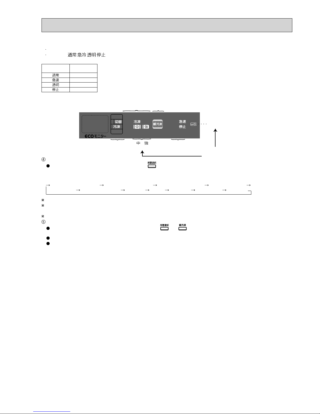
Display
Error
code
Display
Trouble
Detecting method
(*3)
Check point Measures Control
Tens' place
Ones' place
Self-check
Testing
(*1) Ice maker is under testing
Error display
E
01
(*4)
Communication
error of
operation panel
When the following communication errors occur
between control board and
operation P.C. board:
• They transmit and receive
data that has nothing to
do with settings.
•
They cannot transmit
and
receive data each
other for about 2 seconds.
1. Connector CN10K, CN9S, CN5D on control board
5-pin wire to wire connector (hinge)
5-pin connector on operation P.C. board
Repair the
contact failure.
Keep the same operation
as the one before the
communication error has
occurred.
2. Trouble of control board and operation
P.C. board
Replace.
E
02
Communication
error of inverter
When abnormality is found in the
communication between refrigerator control circuit and inverter
control circuit in control board.
(When they do not transmit and
receive data for 10 seconds.)
Replace the
control board.
Compressor OFF.
E03
Trouble of
model judgement
When the model of
control board is different
from that of operation
P.C. board.
1. Check the model name of control board. Replace. Keep operating the unit,
and conduct error code
indication only.
2. Check the operation P.C. board. Replace.
E10
Trouble of ice
making tray
thermistor
When there is a short
or open circuit in the ice
making tray thermistor.
1. Connector CN9S on control board, ice gear
box 6-pin wire to wire connector, 8-pin wire
to wire connector
Repair the
contact failure.
When the compartment door
has been closed for 3 hours
and when freezer compartment thermistor is -10 or
less, ice-detecting operation
starts.
2. Check the resistance of thermistor. Replace.
E11
Trouble of
freezer compartment
thermistor
When there is a short
or open circuit in the
freezer compartment
thermistor.
1. Connector CN9S on control board,
4-pin wire to wire connector
Repair the
contact failure.
After 10 minutes off, the
compressor repeats 30minute ON and 20-minute
OFF.
2. Check the resistance of thermistor. Replace.
E12
Trouble of
defrost
thermistor
When there is a short
or open circuit in the
defrost thermistor.
1. Connector CN9S on control board,
2-pin wire to wire connector
Repair the
contact failure.
The defrost heater won’t
be turned ON.
2. Check the resistance of thermistor. Replace.

24
Display
Error
code
Display
Trouble
Detecting method
(*3)
Check point Measures Control
Tens' place
Ones' place
Self-check
Error display
E13
Trouble of
refrigerator
thermistor
When there is a short
or open circuit in the
refrigerator compartment
thermistor.
1. Connector CN9S on control board,
4-pin wire to wire connector
Repair the
contact failure.
Synchronize the open/
close status of R damper
with that of compressor
ON/OFF.
2. Check the resistance of thermistor. Replace.
E15
Trouble of
versa compartment thermistor
When there is a short or
open circuit in the versa
compartment thermistor.
1. Connector CN9S on control board,
6-pin wire to wire connector
Repair the
contact failure.
• When S-compartment
is used as “freezer”:
S-damper is open when
compressor is turned
on, S-damper is closed
when compressor is
turned off.
•
When S-compartment
is used as other than
“freezer”: S-damper
remains open for the
first 3 minutes and then
closed for the rest of
time.
S-compartment: Versa
(select) compartment.
2. Check the resistance of thermistor. Replace.
E16
Trouble of vegetable compartment thermistor
When there is a short
or open circuit in the
vegetable compartment
thermistor .
1. Connector CN9S on control board, 2-pin
wire to wire connector
Repair the
contact failure.
•
When R-damper is open,
V-heater is turned on.
• When R-damper is
closed, V-heater is
turned off.
2. Check the resistance of thermistor. Replace.
E17
Trouble of ice
making compartment
thermistor
When there is a short
or open circuit in the ice
making compartment
thermistor.
1. Connector CN9S on control board, 6-pin
wire to wire connector
Repair the
contact failure.
• When ice making compartment is used as
“refrigerator”, synchronize
I-damper with R-damper.
• When ice making compartment is used as “ice
making”, synchronize
I-damper with F-damper.
2. Check the resistance of thermistor. Replace.
E18
Trouble of
outside air
thermistor
When there is a short or
open circuit in the outside air thermistor.
Replace the
operation
P.C. board.
Compressor is activated
at “Speed-level 2.”
E23
Trouble of
thermopile
When there is a short or
open circuit in the outside air thermistor.
Relay connector 10 pin 2 positions.
Refer to "5-9.3 Failure diagnosis for the
thermopile (HIKARI i-see Sensor)".
Perform supercool freezing control in emergency
operation mode.
E30
Trouble of
defrost heater 1
(*6)
When defrosting is not
finished in 2 hours.
1. Connector CN2A on control board,
Defrost heater plug and receptacle,
1-pin wire to wire connector,
Thermal fuse 4-pin wire to wire connec-
tor
Repair the
contact failure.
The defrost heater is
stopped and if the next
defrosting finishes in 2
hours, the error code will
disappear.
2. Check the resistance of defrost heater. Replace.
3. Check the continuity of thermal fuse. Replace.
E31
Trouble of
refrigerator
fan motor
• When motor doesn’
t rotate even though
power is on.
• When the waveform,
which indicates the
rotation times of motor,
cannot be detected.
1. Connector CN5D on control board,
Refrigerator fan motor 4-pin wire to wire
connector
Repair the
contact failure.
•
3 minutes later, the refrig-
erator fan motor is reactivated to be checked.
• Until the fan motor gets
to operate correctly, the
buzzer sounds every
time the door is closed.
2. Check refrigerator fan motor operation. Replace.
E32
Trouble of box
fan
• When motor doesn’
t rotate even though
power is on.
• When the waveform,
which indicates the
rotation times of motor,
cannot be detected.
1. Connector CN4D, CN5D on control
board,
Box fan, 4-pin wire to wire con-
nector
Repair the
contact failure.
• 3 minutes later, the box
fan is reactivated to be
checked.
• Until the fan motor gets
to operate correctly, the
buzzer sounds every
time the door is closed.
2. Check box fan operation.
Replace.
E33
Trouble of ice
maker gear
box
When the gear box
operation is not finished
in 30 seconds.
1. Connector CN8K, CN10K on control board, ice gear box
6-pin wire to wire connector, 8-pin wire to wire connector
Repair the
contact failure.
100 minutes later, the
gear box is reactivated to
be checked again.
2. Ice gear box frozen point Replace.
3. Check the trouble of the ice gear box
with the ice making test operation.
Replace.
E34
Clogging of
refrigerant
pipe or trouble related to
compressor
(T0: Defrost thermistor
temperature at power
input, T1: Defrost thermistor temperature when
15 minutes have passed
from the power input)
•When the difference
between
T0 and T1 is T0
T1. (*5)
Check the compressor and the pipe. When cooling operation
returns to normal condition, the display of error
code disappears.
E41
Trouble of
solenoid
three-way
valve
When defrost thermistor
reads -10 or above in five
minutes after the compressor’s startup. (*5)
Connector CN4D on control board,
5-pin connector to three-way valve
Repair the
contact failure.
Check the operation of
solenoid three-way valve
and then open the valve.

25
*1 : The setting of ice making compartment will be displayed and blinks during or after ice making test operation.
*2 : This operation is called the recovery operation:
If the damper has not operated ever once during the compressor operation, make the damper operate when the compressor stops.
*3 : When the resistance is
, the circuit is deemed open-circuited.
When the resistance is 0 , the circuit is deemed short-circuited.
*4 : Once E01 is detected, other errors would be ignored and not displayed on the panel.
*5 : Characteristic value may change in order to improve the product.
*6 : The error codes E50 to E55 are not displayed even if those abnormalities occur at power input.
Therefore, be sure to perform ice making test operation in order to check if any abnormality indicated by these error codes occurs. (See page 22.)
*7 : If those errors still continue for 1 minute after the restart, E56 will be displayed again.
Display
Error
code
Display
Trouble
Detecting method
(*3)
Check point Measures Control
Tens' place
Ones' place
Self-check
Error display
E50
Trouble of
inverter circuit
• When there is any
trouble in the circuit
which detects current
of compressor.
Refer to “Compressor does not operate” at page 30.
The compressor is suspended and reactivated
10 minutes later.
E51
Trouble of
bus-bar voltage
•
When the range of bus-
bar voltage is not approx.
50 ~ 380 V DC.
E52
Trouble of
inverter software
reset function
• When the inverter driving software malfunctions.
E53
Trouble of
startup, synchronization
or overcurrent
detection
• When there is no current at compressor
startup.
• When phase current
exceeds 5.5A at compressor startup.
•
When phase current
exceeds 3.3A during compressor operation.
•
When current of 5.3A or
more runs into the busbar of control board.
E55
Trouble of
control board
(EEPROM
related trouble)
EEPROM (IC11M)
accumulates data necessary for control.
• When the data are not
input accurately.
• When microcomputer
cannot read the data.
Replace the
control
board.
When abnormality occurs in
power input, the compressor is suspended for 10
minutes.
When abnormality occurs in
normal operation, the compressor keeps operating.
E56
Defective wiring connecting
or trouble of
control board
The errors E50 to E53
keep occurring over one
and a half hour. (The
situation, which compressor cannot be operated,
continues.)
Refer to “Compressor does not operate” at page 31.
• Error display starts after
it is regarded as E56.
• Error display continues
until defrosting starts or
cooling operation gets
back to normal. (Error
display doesn’t disappear by unplugging and
plugging the power cord.
*7)
• Try to restart compressor
every 3 minutes.
E57
Inverter drive
module abnormality
When the overcurrent
error is detected before
starting the compressor
(failure of the IC in the
inverter drive module).
Replace the
control
board.
Try to start the compressor every 3 minutes.
(*6)
(*6)
(*6)
(*6)
(*6)

26
MR-E55R-C
MR-E60R-C
5-3 BLOCK DIAGRAM OF PRINTED CIRCUIT BOARD
MR-E55R-C
MR-E60R-C
(1) Ice making cycle
(2) Automatic ice maker circuit
5-4 AUTO ICE-MAKER
CN2A
CN5D
CN10K
CN9S
CN1A
Water pump motor
LED for bacteria
removal from water
tank
6-pin connector
6-pin connector8-pin connector
Ice tray thermistor
Ice making
compartment
thermistor
Water pipe heater
Water tank heater
9-pin connector
Ice making
gear box
Control board
Ice stock
Ice is stocked in the ice storage box.
Ice making capacity is about 100 120 cubes a day.
Stock capacity of ice cubes is about
100 cubes.
(With 8-cube ice tray)
Ice ejection
After the detection lever checks
the amount of ice, the ice tray
is rolled over for ice ejection.
When the ice storage box is
filled with ice, the ice tray does
not roll over.
Water supply
The ice tray is filled with water
from the water tank.
Parts outside/inside refrigerator
For 311V DC system
• Compressor
For 110V AC system
• Defrost heater 1
• Defrost heater 2
• Water tank heater
•
Vegetable compartment heater
• Rotational heater board
• Water pipe heater
• Ice making tray heater
For 5V DC system
• Freezer compartment thermistor
•
Refrigerator compartment thermistor
• Defrost thermistor
• Door switch (for refrigerator compartment, ice compartment & freezer
compartment)
• Ice tray thermistor
• Ice making compartment thermistor
• Vegetable compartment thermistor
• Position-specifying switch in ice
maker gear box
• Versa compartment thermistor
For 12V DC system
• Refrigerator fan motor
• Box fan
• Motor damper
• Ice maker gear box
• Three-way valve
• LED for bacteria removal from
water tank
• I-see sensor motor
• Interior LED
•
Refrigerator deodorization LED
• Versa compartment supercool
freezing LED
• Vegetable compartment LED
Ice making
Ice tray thermistor watches
and controls the ice making
operation
Operation P.C. board
• Setting up temperature, feature, quick mode and eco mode for each
compartment
• Display of self-check
• Outside air thermistor
• Buzzer
Control board
Control circuit of refrigerator
• Read/control each compartment temperature (Neuro-fuzzy)
• Control on timers
• Operation control of the parts such
as fan motor or heater, etc. equipped
inside/outside
Inverter control circuit of compressor
• Inverter control of compressor
• Inverter-drive power module
• Detection of bus-bar voltage

27
Ice making test completes
about 20 seconds later.
(3) Operation by ice making test
Press the
switch for 5 seconds or more.
(See 5-2(1) “• Self-check
and error display method
and operation,
Ice
making test operation”
Ice stock detective
lever detects the
amount of ice.
Detective lever once
comes down to detection
point then returns to the
original position.
The ice tray is
rolled over and the
system is reset.
The ice tray rolls
over once to drop the
ice, then returns to
the original position.
Water pump motor
is operates.
Remove the lid of
the water tank then
check the sounds of
water running.
Completion
When abnormality
occurs, the error code
is displayed on the
panel.
Inspect the abnormal
points by referring to
page 23-25.
Ice tray
Detection lever
(Upper ice making compartment)
[Check point of automatic ice maker operation]
* Never touch the automatic ice maker while it is operating.
After the operational test, a popping sound is heard several times because the operation of three-way valve is checked automatically. During the operation, do not insert a hand into the automatic ice maker.
(4) Maintenance for water pump and water pipe
The inside of the pump can be cleaned after disassembling the pump in the water tank.
The inside of the pipe can be cleaned after disassembling the water supply pipe in the tank holder. Follow the procedures below
when disassembling, cleaning, and assembling the pump and the pipe.
Be sure to explain to customers that they need to clean the water pump and the water supply pipe once a month.
After the test run, a “pop” sound is heard several times to automatically confirm the proper operation of the three-way valve.
(Lower-left part of refrigerator compartment)
Check here.
Water pipe · Tank holder
1. Pull out water supply
pipe. Wipe the tank
holder with clean cloth.
• Do not let water flow into
the tank holder.
Water pump
1. Pull out the pipe.
2. Turn the tank
pump to detach.
5. Put the parts back in the reverse order of disassembly.
3. Pull out the tank pipe, turn the cap
to remove, and then wash the propeller with water.
• The propeller is made
of the magnet.
Wash it well with water
so that no alien substance remains on it.
4. Remove the light-type bacteria removing filter and
wash it in water.
Normally the filter needs not be replaced. However, replace it
in the following condition:
• When the filter is clogged by passing something other than
water through the filter.
• When the filter is broken.
In such a case, contact the dealer where you purchased
this refrigerator.
Light-type bacteria removing filter
Cap
Propeller
Tank pipe
Cover
Tank
pipe
Water
tank
Water pump & Light-type bacteria removing filter
3. Reverse steps to replace the pipe.
Water
pipe
Tank holder
Side A
Side B
Water pipe
• Replace the water
pipe.
Be sure that sides
A and B fit flush to
each other.
2. Separate pieces and wash with water.
Packing
Aluminum pipe
• Twist the
aluminum
pipe to
replace it.
(5) Troubleshooting for automatic ice-maker
Trouble with ice-making
Water or ice is on the
ice tray
The ice-maker gear box may be defective, cooling may be poor or ice cubes may be full in the ice storage box.
The ice does not
come out from the
tray
1. Check inside of the ice storage box. • Ice cubes are not stored flatly
and the amount is detected
as full.
•
Food inside the ice storage box
Inspection
2. Measure the resistance of ice tray thermistor circuit. • Open circuit ( ) or short
circuit (0 )
Replace the ice tray
thermistor.
3. Check if the temperature of the freezer compartment
is cool enough.
(It takes longer to make ice during summer days
or if the door is frequently opened.)
• Not enough
Poor cooling
No water or ice in the ice tray
The water saucer may be defective, or the ice tray may get cracked.
Water in
water sau-
cer
4. Check the water pipe for dirt and foreign objects. • Clogging
• Freezing (For freezing, check
installation and measure
the resistance of water pipe
heater and tank heater.)
Clean the water pipe.
Deice
Check connection of
water pipe heater and
tank heater.
No waterdrops in water
saucer
5. Check the condition of ice tray. • Broken or cracked
• Not placed properly
Replace the tray.
Reinstall it properly.
6. Disassemble the water pump and check the inside of
the pipe.
• Dirt or foreign objects
Repair and explain to the
user for proper usage.
7. Tank pipe is clogged, has a hole or is not
properly installed.
• Clogging, disconnecting
• Hole or crack
Clean/Reinstall it prop-
erly.
Change the tank pipe.
8. Check the coil resistance of pump motor. • Open or short circuit
Check the water pump.
9. Check if there are any dirt or foreign objects which
are difficult to remove in the water tank. Also, check if
there is any crack or deformation on the tank.
• Crack or deformation
Change the water tank.
Water in the tank holder
10. Check the water pipe for dirt and foreign objects.
Also, check the water pipe position and connection.
• Clogging, disconnecting
• Hole or crack
Clean/Reinstall it prop-
erly.
Replace the pipe.
Chained ice,
water leaking from the
ice server
11. Check the water pump operation by the ice-making
test
• Water filling period is longer
than 9 seconds.
Replace the control
board.
12. Water spill at the installation of water tank or more water over the full water level may cause formation of
chained ice.
13. Measure the water pump coil resistance. • Open or short circuit Change the water pump
motor.

Excessive cooling No cooling, poor cooling
28
MR-E55R-C
MR-E60R-C
5-5 FLOWCHART OF TROUBLE CRITERION
Refrigerator compartment/ Slide chilled compartment
[1]
Set the temperature to
“Low”.
No
Keep the food away
from air outlet.
Yes
Yes
Set the temperature to
“High”.
No
Proceed to [5] at page
32.
No
No
Normal
No
Yes
Yes
The baffle does not operate
Yes
Repair the frosted part.
Refrigerator compartment
thermistor abnormal
Replace the refrigerator
compartment thermistor.
Is the temperature of
refrigerator compartment/ set to “Low”?
Only food around the
air outlet gets frozen.
Is the temperature of
refrigerator compartment/ set to “High”?
Check the refrigerator compartment thermistor.
Replace the motor damper (for refrigerator compartment/slide chilled compartment)
Motor damper is combined with
fan grille assembly.
Is the motor damper (for refrigerator compartment/slide
compartment) covered with frost?
Expose the damper (for refrigerator compartment/slide compartment) so that its operation can be visibly checked and
conduct an ice-making test. Does the baffle open/close?
(Wait 1 minute for self-check).
(See “Self check method and its operation, Ice making
test operation” at page 22.)
Dip refrigerator compartment thermistor into ice water (0 ),
disconnect the 2-pin connector, and measure resistance
between (white) and
(white).
• Resistance at 0 : approx. 6-7k .
CN9S
4-pin connector
Weak
Low
HighMiddle
Refrigerator
compartment
Cooling Strong
Refrigerator compartment
thermistor
Control board
Adjustment of the set temperature is
possible.
Page 20
Open the refrigerator
compartment door and
attach a magnet on the
door switch to check that
cold air blows from the
outlet. (See 1)
Refrigerator
compartment
Versa
compartment
Ice
making
compartment
Attach a
magnet bar
here.
1

Poor cooling
29
CN50G
CN1A
CN1 CN2
Filter board
Control board
Noise filter
Compressor
Lead wire assembly
Reactor
Motor
protector
2
-pin
connector
2
-pin
connector
Not cooling at all (In case any error codes doesn’t appear as shown in pages 30, 31 even though switch is pressed for 5 seconds)
Freezer compartment
[2]
Exchange the unit.
Replace the lead wire
assembly (lead wire of
compressor).
Abnormal
No
Yes
Set the temperature to “High”.
No
Proceed to “The refrigerator fan motor does not work.”
No
No continuity
Abnormal
Normal
Replace freezer compartment thermistor
1
Is the set temperature of freezer compartment set to “High”?
Does 110V AC run between and terminals of CN1 on filter board?
3
Defective thermistor
Check freezer compartment thermistor.
When compressor
operates,
E41
is displayed as a result
of self-check.
Normal
Control board
4
-pin connector
Freezer
compartment
thermistor
CN9S
Is the voltage between and , terminal of
CN2 on the filter board 110V AC?
Yes
Remove the CN1A connector on the control
board and the CN2 connector on the filter
board and check for continuity between the
CN1A terminal
and the CN2 connector terminal on the wiring side. (Check for short
and/or open circuit on the motor protector.)
Detach connector CN50G on control board and check the resistance
respectively between terminals of
, and
:approx. 12.4 .
Check the error display of selfcheck after turning on and off the
power supply.
With all the connectors connected.
Inverter-related parts may be
defective. Conduct ice making
test operation. (See pages 30, 31
for error codes.)
Continuity detected
Continuity detected
No
Inspect power-supply wiring such as power cord and
breaker etc.
Replace the filter board.
Motor protector (open circuit)
Just in case, by measuring the
resistance, ensure that the circuit is open.
Measure the resistance of compressor’s winding between terminals of black, white, and red:
approx. 12.4 .
Compressor does not operate
[3]
Exchange the
unit.
Yes
Is refrigerator in the demonstration mode?
Release the demonstration mode. (See page 11.)
No
Dip freezer compartment thermistor into ice water (0 ), and
measure the resistance between terminal (white) and
(white) by detaching 2-pin connector at the left-back bottom
of vegetable compartment.
•Resistance at 0 :approx. 6~7k .
Yes
Yes
Does cool air come out of air outlet when opening the refrigerator
compartment door and attaching a magnet bar on the door switch ?
2
Adjustment of the set temperature is
possible.
Page 20
No continuity

30
Inverter-related indication “Compressor does not operate”
Error
code
Abnormality
Possible cause
Symptom Measures
E50
• Abnormal
start-up
• Abnormal synchronization
• Trouble of
overcurrent
detection
• When there is
any trouble in
the circuit which
detects phase
current of compressor.
E51
Compressor
does not
rotate.
Replace the control board.
Bus-bar
voltage is
abnormal.
• Power supply
voltage is abnormal.
• Defective reactor on the N/F
board
Replace the control board.
E52
E52 displays again.
Check the error code by performing the ice making test operation.
Trouble of
inverter circuit
Compressor
does not
rotate.
Arrange
power supply to obtain
the rated
voltage,
99~121V.
Start
Measure the voltage of
power supply.
99V or
less
121V or more
Does 121V AC run
between CN1A terminals
and , on
the control board?
(See page 42.)
Arrange power supply to make the voltage within 121V and conduct the following
checks.
Check the
connection
between filter
board and
control board.
Connect
them
properly.
Abnormal
Replace the
filter board.
Yes Normal
Replace the
control board.
No
Trouble of
inverter software
reset function
• When the
inverter driving
software malfunctions due to
electric noise.
Unplug the power cord and wait more than 10 minutes then plug it again
No error code display
Explain to customer.
E53
• Compressor
motor gets
locked.
• Defective circuit
on control board
• Defective contact of CN50G
on control board
Compressor
does not
rotate.
Compressor
does not
rotate.
Start
Remove the CN50G
connector on the control board, and measure the resistance
on the compressor.
Are the resistances
between the terminals
-
, - , and
- respectively
approx. 12.4
(20 )?
Exchange
the unit.
Yes
*If control board is normal, compressor is energized
every 10 minutes.
Compressor vibrates at startup when it is being ener-
gized. Touch it with your hand to check.
Measure the
resistance
of compressor’s winding
between each
terminal. Is
the resistance
approx. 12.4
(20
)?
No
No
Replace the
compressor.
*Replace lead wire assembly.
*Is compressor
energized at
startup?
Check the connection status
of the CN50G connector on
the control board.
No
Correct the
connection of
the CN50G
connector on
the control
board.
Abnormal
Replace the
control board.
Yes
Yes Normal

31
Inverter-related indication “Compressor does not operate”
Error
code
Abnormality Possible cause Symptom Measures
E56
Compressor
cannot be
activeted for
more than 1.5
hours.
1. Locate the trouble and decide the measures.
• Decide the measures by checking the followings.
(1) Defective connector connections.
(Board-side, wire to wire, comp-side)
(2) Resistance of compressor’s winding
2. Flowchart of troubleshooting
• Defective wiring continuity
• Trouble of the
control board
• Defective connection of connectors related
to compressor
(board-side,
relay, comp-side)
• Defective wiring
connecting of the
compressor
• Trouble of control board
• Trouble of compressor
3. Recheck after measures
• After any measures are taken, unplug and plug power cord
again to check if the compressor operates properly.
• If the compressor can operate properly for more than 1
minute after power cord is plugged again, it’s presumed
that the cause of trouble is eliminated.
*If the cause of trouble cannot be eliminated,
E56 will be dis-
played again 1 minute later after the power cord is plugged
again.
*If the control board has been replaced, E56 won’t be dis-
played even though the cause of trouble is still not eliminated. In such a case, perform the ice making test operation
to check what the error is. At the same time, also confirm
that the compressor is operating for more than 3 minutes and
each compartment is getting cooled.
start
Connector CN50G on the
control board is properly
connected?
The connector of compressor
is properly connected?
Remove the CN50G
connector on the control
board, and measure the
winding resistance on the
compressor. , and
(Point1). Is the resistance
approx. 12.4Ω (at 20ºC)?
Measure the
resistance of
compressor’s
winding between
individual
terminals (Point 2).
Is the resistance
approx.
12.4Ω
(at 20ºC)?
Is compressor being
energized at startup?
Exchange the unit.
Connect properly.
Exchange
the unit.
Replace the lead wire assembly.
Replace the control board.
Replace it only when error display
keeps blinking even though all the
above mentioned connectors are
properly connected.
Check
No
Yes
Yes
Yes Yes
Yes
No
NoNo
No
Treatment
Compressor
Control board
Point+2 (to measure resistance)
Point+1 (to measure resistance)
For checking the connection
to compressor
For checking the lead wire
assembly to compressor
Lead wire assembly
CN50G
E57
Replace the control board.
Inverter drive
module abnormality
Failure of the
inverter drive module in the control
P.C. board
Overcurrent is
detected in the
inverter drive
module before
starting the compressor, and the
compressor does
not start rotating.

Poor cooling
32
Contact failure of
connector.
Connect it properly.
Poor defrosting
[4]
The refrigerator fan motor does not work
[5]
No
No
Yes
Yes (heats up)
Check the following and explain the
result: half-open door, space between
gaskets, the amount of ice.
Replace the defrost heater 1 and the
thermal fuse.
Check the resistance of the defrost
thermistor.
*1 The compulsory defrosting will not
work when the temperature of
the defrost thermistor is 14°C or
more.
CN9S
CN1A
CN2A
Control board
4-pin connector
4-pin connector
1-pin connector
Thermal fuse
Defrost heater 1
Defrost thermistor
Check if the connector on
the door switch is connected properly. If it is, replace
the door switch.
Abnormal
Normal
Interior LED
is not turned
on and off.
Interior LED is turned on and off properly.
OFF
etc
ON
R-door (right, left): closed
Door of the ice making
compartment : closed
Any one of the doors
is open
Doors
3-Pin connector
between
and
1
3
1 2
5~10mm
Door of vegetable
compartment
Door of freezer
compartment
Left door of refrigerator
comparttment
Door of ice
making
compartment
Door
of
versa
compartment
Right door of refrigerator
compartment
Door switches for refrigerator compartment (right and left) and ice making compartment
No
Not rotating
Yes
Replace refrigerator fan motor.
Check if CN5D connector on control
board is connected properly.
If it is, replace the control board.
Running
No
continuity
Connect the connectors properly.
Continuity detected
Replace refrigerator fan motor.
CN9S
CN5D
Control board
8
-pin
connector
4
-pin
connector
Refrigerator
fan motor
Reed switch board
3
-pin connector
4
-pin connector
2
-pin
connector
Refrigerator compartment
(right and left)/ Ice making
compartment door switch
Freezer compartment
door switch
2
Unplug and plug the power cord to check if box
fan is rotating.
3
2
Check if there is continuity between thermal fuse
and defrost heater 1.
4
Check the continuity by
disconnecting the CN9S
on the control board.
1
<Control board>
Compulsory defrosting
Short circuit
CN7M
Note: Refrigerator fan motor is combined
with fan grille.
Note: Refrigerator fan motor is combined
with fan grille.
5
If any one of those doors is open, the switch between
and , terminals of 3-pin connector, will be OFF.
1
Short-circuit the terminals and of the compulsory
defrosting terminals (CN7M) of the control board to actuate
the compulsory defrosting function and check whether the
defrost heater is working properly. *1
1
Check the door switch for continuity.
• Open and close the refrigerator door several times and
check if the interior LED will be turned on and off (interior
LED should get turned off when the door comes 10 mm
close to the refrigerator body .)
• Close the refrigerator compartment door until the LED is
turned off . Open and close the ice making compartment
door , and from the space of refrigerator compartment
door, check that the interior LED is turned on and off.
Unplug and plug the power cord to perform self-check on
refrigerator fan motor. Is the display indicating abnormality?
Check if there is continuity in 4-pin fan motor connector in
versa compartment.

Excessive cooling
Poor cooling
33
Vegetable compartment
[6]
Set the temperature to
“Low”.
No
Set the temperature to
“High”.
No
Set the temperature to
“Middle” or “High”.
Yes
Is the temperature of
vegetable compartment
set to “Low”?
Is the temperature of
vegetable compartment
set to “High”?
Is the temperature of
freezer compartment
set to “Low”?
Yes
No
CN2A
CN5D
CN1A
CN9S
CN10K
CN5D
5-pin connector
Operation P.C. board
Outside air
thermistor
TH1
Vegetable
compartment heater
Vegetable
compartment thermistor
6-pin connector
2-pin connector
Motor damper
(for vegetable copartment/
versa compartment)
2-pin connector
Control board
Not frosted
No
Expose the damper (for
refrigerator compartment/
slide compartment) so that
its operation can be visibly
checked and conduct an
ice-making test. Does the
baffle open/close?
Connect the connector
properly.
No
Disconnect CN5D and measure
the resistances between and
, and between and .
Check that the winding of motor
damper (for vegetable compartment/ versa compartment) has a
resistance of approx. 415 .
0
or
Is 6-pin connector which is in connector cover
on the back of ice maiking compartment connected properly?
(6-pin connector is connected to motor damper.
Refer to the figure below.)
Defective thermistor
Replace the vegetable
compartment thermistor.
Check the thermistor on the vegetable compartment.
1. Dip the thermistor into ice water with a temperature of 0 .
2. Remove the 4 - pi n c onn ec tor f ro m th e c onne c tor b ox on th e
upper-left-front.
3. Measure between the terminals -.
• Resistance at 0 : Approx. 6~7k
Is the motor damper covered with frost?
Frosted
Repair the frosted part.
Replace the motor damper (for vegetable compartment/versa compartment).
Replace the fan grille as well as the motor
damper because they are combined together.
Normal
Yes
No
Yes
Is connector CN5D on
control board connected
properly?
Normal
Adjustment of the set temperature is
possible.
Page 20
Yes

34
only applies to versa compartment. Excessive cooling
Versa compartment/ Ice making compartment
[7]
No cooling; poor cooling
Set the temperature to “Low”.
Yes
No
Refer to the section:
“The refrigerator fan
motor does not work”.
Not frosted
The baffles
do not function
CN9S
CN5D
Control board
6
-pin connector
Versa
compartment thermistor
Motor damper
(for versa compartment/
vegetable compartment)
6
-pin connector
Ice making
compartment
thermistor
Motor damper
(for refrigerator compartment/
ice making compartment)
Only the food around
cool-air outlet is excessively cooled.
Does cool air come out
of air outlet when opening the refrigeratorcompartment door and
attaching a magnet bar
on the door switch?
Make the operation of
motor damper (for versa
compartment/vegetable
compartment) visible,
and conduct ice making
test. Check that the baffles open and close. (Wait
1 minute for self-check.)
(See “• Self-check and
error display method and
operation, Ice making
test operation” on page
22.)
Connect the connector
properly.
No
Disconnect CN5D and measure the resistance between
and , and between and .
Check that the winding of motor
damper (for versa compartment/
vegetable compartment) has a
resistance of approx. 415 .
0
or
Is 6-pin connector which is in connector cover
on the back of ice making compartment connected properly?
(6-pin connector is connected to motor damper.
Refer to the figure below.)
Refrigerator
compartment
Versa
compartment
Ice
making
compartment
Attach a
magnet bar
here.
1
Defective thermistor
Replace the versa
compartment thermistor.
Check the versa compartment thermistor.
Dip the versa compartment thermistor into the ice water
(0 ) and disconnect 6-pin connector for fan grille at the
back of versa compartment. Measure the resistance
between terminals (white) and (white).
• Resistance at 0 : Approx. 6~7k
Defective thermistor
Check the ice making compartment thermistor.
Dip the ice making compartment thermistor into the ice
water (0 ) and disconnect 6-pin connector of fan grille at
the back of ice making compartment. Measure the resistance between terminals (white) and
(white).
• Resistance at 0 : Approx. 6~7k
Is the motor damper covered with frost?
Frosted
Repair the frosted part.
Replace the motor damper (for versa compartment/vegetable compartment).
Replace the fan grille as well as the motor
damper because they are combined together.
Normal
Yes
No
Yes
Is connector CN5D on
control board connected
properly?
Keep food away from
air outlet when storing
food.
Is the
temperature
set to “Low”?
Which operation mode is
versa compartment set to?
It is set to “Soft freezing”.
Set the temperature to
“High”.
Set the temperature to “High”.
Which operation mode is versa compartment set to?
Check the set temperature in freezer compartment. Is the temperature set to “High”?
Is the temperature
set to “High”?
It is set to “Soft freezing”.
It is set to “Freezer”.
Yes
No
No
No
No
Yes
1
Normal
Replace the ice making
compartment thermistor.
Adjustment of the set temperature is
possible.
Page 20
Yes

Components/
Part Name
Check Method and Criterion
Parts Mounted
Position
35
MR-E55R-C MR-E60R-C
5-6 TROUBLE CRITERION OF MAIN PARTS
Compressor
Motor
protector
In the machine
chamber at the
rear side of the
frame
Black Red
White
1
1
2
2
Contact point
Model
MM3-71CCV
100 ± 50 or more
Energize it at 17.0A, 25 for 16 seconds at the longest
.
61±8 or less
Connected
point
Open
Close
Measure the resistance with a tester. (Ambient temperature: Room temperature)
Normal Abnormal (faulty)
Less than 1
Open circuit (0)
In the machine
chamber at the
rear side of the
frame
Refrigerator
fan motor
In the fan grille
of the freezer
compartment
Model
UDQM002B3
DC brushless
10
150 (Mixed flow fan)
Number of poles
Diameter
Normal
Abnormal
(faulty)
Between and (GND and IC
Power): About 12k
Between and :
open circuit ( )
Between and :
short circuit (
0
)
Measure the resistance with a tester. (Ambient temperature : Room temperature)
Between and (Power and
IC Power):
1
1
2
3
4
2 3 4 : Pin No.
IC
IC Power
Power
FG
GND
Measure the resistance
with a tester.
Machine
chamber fan
motor
In the machine
chamber at the
rear side of the
frame
Measure the resistance with a tester. (Ambient temperature: Room temperature)
Normal
Abnormal (faulty)
Between and (GND and
Vcc): About 25k
Between and :
open circuit ( )
Between and (Vs and Vcc):
Between and :
short circuit (0 )
4321 Pin No.
Model 4715JL04WS16G51
Operation method
During compressor operation
Model EFI100E13DHH
Rated input
W
45 (1620 rpm)
Starting current
A
4.0
Running current
A
0.69 (1620 rpm)
(For only 1 minute after startup)
Normal
Abnormal
(faulty)
Winding
(Black-White)
(White-Red)
(Red-Black)
12.4
(20 )
Open ( )
or
short circuit (0 )

Components/
Part Name
Check Method and Criterion
Parts Mounted
Position
36
Red
Yellow
Blue White
Water pump
motor
Under the water
tank holder in
refrigerator compartment
Measure the resistance with a tester. (Ambient temperature : Room temperature)
Normal
Abnormal (faulty)
16 (Approx.)
Open ( ) or
short circuit
(0 )
Motor damper
for refrigerator
compartment/
ice making
compartment
In the fan grille
for freezer
compartment
Connector is at
the left-back bottom of refrigerator compartment.
Measure the winding resistance.
Normal
Abnormal (faulty)
415
(Approx.)
Open ( ) or
short circuit
(0 )
Winding
Blue-White
Red-Yellow
(
)
Red
Yellow
Blue White
Motor damper
for versa com-
partment/vegetable compartment
In the fan grille
for freezer
compartment
Connector is at
the back of versa
compartment.
Measure the winding resistance.
Normal
Abnormal (faulty)
415
(Approx.)
Open ( ) or
short circuit
(0 )
Winding
Blue-White
Red-Yellow
(
)

Components/
Part Name
Check Method and Criterion
Parts Mounted
Position
37
Vegetable
compartment
heater
Water pipe
heater
At the bottom of
the vegetable
compartment
(inside polyurethane foam)
The connectors
are in the connector box on
the ceiling of
the vegetable
compartment
Under the water
tank holder
Normal
Abnormal (faulty)
3.0k
(Approx.) Open circuit ( )
Measure the resistance with a tester. (Ambient temperature : Room temperature)
Operation method
When ice-making thermistor has reached approx. 10 or
below, the heater is turned on with energizing rate adjusted by the set temperature of refrigerator compartment and
freezer compartment.
Normal Abnormal (faulty)
1.7k (Approx.)
Open circuit ( )
Measure the resistance with a tester. (Ambient temperature : Room temperature)
Operation method
The heater is turned on when vegetable compartment
thermistor has reached a lower temperature than the set
temperature for vegetable compartment.
Defrost heater 1
At the drip tray
under the evaporator of the
freezer
compartment.
Rated input
150
The heater is energized while defrosting.
(Defrosting is finished when the evaporator is 14±1.5 or more)
W
Operation method
Measure the resistance with a tester. (Ambient temperature : Room temperature)
Normal Abnormal (faulty)
81
(Approx.)
Open circuit ( )
Water tank
heater
Under the water
tank holder
Normal
Abnormal (faulty)
3.0k
(Approx.) Open circuit ( )
Measure the resistance with a tester. (Ambient temperature : Room temperature)
Operation method
The heater is turned on with energizing rate adjusted by
the set temperature of refrigerator compartment.
Defrost heater 2
Embedded in
the evaporator
(protected with
the dedicated
aluminum piping)
Rated input
86
The heater is energized while defrosting.
(Defrosting is finished when the evaporator is 14±1.5 or more)
W
Operation method
Measure the resistance with a tester. (Ambient temperature : Room temperature)
Normal Abnormal (faulty)
141
(Approx.)
Open circuit ( )

Components/
Part Name
Check Method and Criterion
Parts Mounted
Position
38
Rotational heater
board
In partition of
refrigerator compartment door
Normal Abnormal (faulty)
1.5k (Approx.) Open circuit ( )
Measure the resistance with a tester. (Ambient temperature : Room temperature)
Operation method
While compressor is operating, the heater is turned on.
When compressor stops, the heater is suspended for the
first 20 minutes and then reactivated.
Ice making
tray heater
Lower part
of ice tray
Measure the resistance with a tester. (Ambient temperature: Room temperature)
Operation method
During CRYSTAL ICE mode
(The heater is turned on 5 minutes after water supply for
up to 4 hours.)
Normal Abnormal (faulty)
1.0k (Approx.) Open circuit (
)
Thermistor
Measure the resistance with a tester according to the following graph.
(Thermistor resistance values against temperature)
• Resistance measured under the ambient temperature from -50 to +50
1. 200 to 500 k •••••••••••••••••Normal
2. Out of the above range •••••••••Abnormal
Thermistor Check Procedure
• Thermistor resistance value will vary
with the change of temperature.
•
Take the temperature around the ther-
mistor, and then measure thermistor
resistance using a tester.
The relation between resistance and temperature is as shown on the left side.
0
0
5
10
15
20
25
30
35
10 20 30-10-20
Thermistor resistance
values against temperature
Outside air thermistor
(In the operation
P.C. board)
Resistance values
Temperature
Inner
thermistor
Refrigerator
compartment
Ice making tray
thermistor
Freezer
compartment
Defrosting
Versa
compartment
Ice making
compartment
Vegetable
compartment
Troubleshooting with self-check
(1) If the self-check indicates the abnor-
mality of thermistor when the power is
turned on, measure the resistance of
the thermistor.
• If there is a short circuit in the thermistor, there may be a defect in the
contact of the connector or the element of the thermistor.
(2) When the self-check indicates the
abnormality of thermistor a few seconds after the power is turned on,
check the contact of the connector.
Defrost
thermistor
Evaporator
Ice making
thermistor,
Versa
compartment
thermistor,
and Freezer
compartment
thermistor
In the fan grille
of each
compartment
Vegetable
compartment
In the back of
partitions
between
Freezing and
Vegetable
compartments
Ice making
tray
thermistor
In the ice
making
compartment
Refrigerator
compartment
thermistor
Back of the
refrigerator
control panel
Outside air
thermistor
In the operation
P.C. board

Components/
Part Name
Check Method and Criterion
Parts Mounted
Position
39
Three-way
valve
In the machine
chamber at the
rear side of the
frame
Normal
Abnormal
54~66
(Gray
[common] A/ A/ B/
B each phase)
Open ( ) or
short circuit (0 )
A 5
A 2
B1COM
3B4
12345
BA
COM
BA
Check the operation by following either (1) or (2) below. When a popping sound is
heard 1 to 25 times, it is considered that the valve is operating normally. The sound
is clearly heard around the back of the product.
(1) Reset the power supply. Check the operation right after this.
(2) Ice making test. Check the operation right after the test is over.
Model NSCE001DC1
Check the operation of three-way valve
LED for bacteria
removal from
water tank
(12V DC)
On the external
surface of the
tank holder
LED lighting
duration
• After water is supplied to the ice tray.
• After the ice level sensor lever detects that ice storage
becomes full.
• While the door is kept open for maximum of 5 minutes.
Abnormal criterion
When the door is opened, LED goes out within 5 minutes.
Make sure if the connector is securely connected.
LED
Note: LED cannot be replaced individually because
it is embedded in the tank holder.
Photosynthesis LED (2 pieces)
LED lighting
duration
Always
Abnormal
criterion
Means
Check with the diode range( ) of tester.
(Use a tester equipped with diode range.)
The pointer of the tester does not shake when measuring
between 2-pin connector No.1 (-) and No.2 (+). Make
sure the pointer of the tester does not shake even if the
polarities are reversed. Resistance: Short-circuited (0Ω)
LEDs light in following
colors at the above timing.
Photosynthesis LED: Orange
Photosynthesis
LED
21
LED
Use a tester equipped
with a diode range
LEDs
(Vegetable com-
partment)
On the ceiling
vegetable compartment
(Vegetable
compartment
LED board)

Components/
Part Name
Check Method and Criterion
Parts Mounted
Position
Interior LED
(12V DC)
LED lighting
duration
It lights up while the refrigerator compartment door is open.(If the
door stays open for 60 minutes in a row, the LED automatically goes
off. Once the door is closed, it will light up again next time the door is
opened.)
Abnormal criterion
The LED does not go on at the above timing.
In the refrigerator
compartment:
on the left and
right wall towards
the front of the
compartment
(Interior LED
control board)
Refrigerator
deodorization LED
(12V DC)
LED lighting
duration
1. While the i-see sensor motor is moving
2. During the defrost process, or for about 10 minutes after defrosting
completes
3. For about 90 seconds after the compressor stops
4. While the compartment door (refrigerator, ice making, and/or
freezer compartment) is opened (for 5 minutes at the maximum)
This LED and the versa compartment supercool freezing LED light
up simultaneously.
Abnormal criterion
The light does not go on at the above timing.
In the refrigerator
compartment:
in the control panel
which is towards
the back of the
compartment
(Refrigerator
deodorization LED
control board)
Versa compartment
supercool freezing
LED (12V DC)
LED lighting
duration
1. While the i-see sensor motor is moving
2. During the defrost process, or for about 10 minutes after defrosting
completes
3. For about 90 seconds after the compressor stops
4. While the compartment door (refrigerator, ice making, and/or
freezer compartment) is opened (for 5 minutes at the maximum)
This LED and the refrigerator deodorization LED light up
simultaneously.
Abnormal criterion
The light does not go on at the above timing.
On the ceiling near
front in the versa
compartment
(Mounted on the
i-see sensor motor:
Versa compartment
supercool freezing
LED control board
)
40

Components/
Part Name
Check Method and Criterion
Parts Mounted
Position
i-see sensor
motor (12V DC)
Model NSEV001DA1
Resistance 126
- 154 (common-A/A/B/B each phase)
Abnormal criterion
1) Operation check… Refer to “Operation check of the i-see sensor
motor” below.
2) Resistance check… Open or short
<Operation check of the i-see sensor>
The i-see sensor motor operates by performing (1) or (2) below. Open the versa compartment
door to visually confi rm the operation.
(1) Power reset (Check the operation right after the power is reset.)
(2) Ice making test (Check the operation right after the ice making test.)
Operation of the i-see sensor motor
The operation pattern during the operation checking is different according to which starting
procedure, (1) or (2), was selected.
(1) The operation was started by the power reset
The motor moves from back to front.
The motor moves from front to back, and stops
at the prescribed position.
(2) The operation was started by the ice making test
The motor moves from front to back
The motor moves from back to front.
The motor moves from front to back, and stops
at the prescribed position.
On the
ceiling
near
front in the versa
compartment
Front
Back
Front
Back
41
5
4
3
2
1
A
B
COM
A
B

42
280~340V DC
Compulsory
defrosting by
short circuit
CN7M
15 16 171413121110
9
CN9S
18
87654321
CN10K
34567128
CN4D
1
Rotational heater board
3
Water pipe heater
5
Vegetable compartment heater
7
Defrost heater 2 (for evaporator pipe)
9
Defrost heater 1 (for Glass tube heater)
CN2A
+5V DC
(Inverter circuit)
Compressor
1 U phase
3 V phase
5 W phase
CN50G
1
3
5
7
110V AC
Ice tray heater
Tank heater
CN1A
21
16151413121110
9876543
CN5D
+12~20V DC
(Inverter circuit)
+5V DC
(Refrigerator
control board)
+12V~14V DC
(Refrigerator
control circuit)
13.5 V com
Box fan (Speed control)
Box fan FG signal
GND
GND
13.5 V com
Refrigerator fan motor FG signal
Fan motor (+)
Reception of operation panel data
Transmission of operation panel data
Ice maker (reverse)
Ice maker (rotation)
Water pump (+)
Ice maker position switch
Water pump (-)
GND
I-see sensor motor
HIKARI (optical) air deodrization LED +
Supercool freezing LED
7.4V
Vegetable compartment LED
Door switch input for freezer compartment
Door switch input for refrigerator compartment / ice making compartment
Thermopile (Object)
Thermopile (Thermistor)
Freezer compartment thermistor
Ice making compartment thermistor
Vegetable compartment thermistor
Versa compartment thermistor
Defrost thermistor
Ice making tray thermistor
Refrigerator compartment thermistor
GND
5V com
Damper for vegetable compartment/
versa compartment
Damper for ice making compartment/
refrigerator compartment
Interior LED (left)
Interior LED (right)
LED for bacteria removal from water tank
Power supply
of three-way
valve
1312 141110
987654321
The capacitor that is used for the inverter is charged to 330V DC,
so electric charge remains for a while even after power off.
Therefore, an electric shock may occur if the charging portion is
touched by hand.
Short-circuiting between J91C and J92 for 20 seconds or longer
with a tool such as a flat-blade screwdriver allows the capacitor to
discharge safely. When replacement of the control board follows,
be sure to perform this operation.
After discharge, measure between the C91C terminals + and –
with a tester. Before inspection, be sure to check that the voltage
is 10V DC or lower.
CN61L
21
MR-E55R-C
MR-E60R-C
5-7 TEST POINT DIAGRAM OF FILTER BOARD
110V AC
3
1
CN1
MR-E55R-C
MR-E60R-C
5-8 TEST POINT DIAGRAM OF CONTROL BOARD

43
5-9 TROUBLESHOOTING FOR SUPERCOOL FREEZING OPERATION
Symptom/Problem Possible cause Explanation to the customer/Solution
1
Supercool freezing does not keep foods fresh.
Supercool freezing does not work.
Improper supercool freezing operation
• The amount of drip from meat and/or
fi sh is same as before.
• Meat is dried out.
• Potatoes become fl oury.
• Vegetables lose their crispy texture.
• Bamboo shoots are sinewy.
• Rice is not tasty.
• The versa compartment is not set to the
soft freezing mode.
• Supercool freezing button is not pressed.
• Food was added to the compartment in the
middle of the supercool freezing mode.
• Food is wrapped in aluminum foil or paper.
• A separate item of food is on the top of the
food for supercool freezing and preventing
even supercool freezing.
•
Food that had thawed out once was refrozen.
• Food is old or expired.
• Hot food and cold food are put in the
compartment at the same time.
• Set the versa compartment to the soft
freezing mode. (Supercool freezing is only
available in the soft freezing mode.)
• Be sure to press the supercool freezing
button.
• Food that was added to the compartment
in the middle of the supercool freezing
mode may not be frozen.
•
The temperature of wrapped food is difficult to
be detected by the supercool freezing sensor.
• Refrozen food and old food may not
besupercool-freezed occasionally.
• As the cooling of hot food takes precedence over that of cold food, the cold food
may not be supercooled occasionally.
2
Food does not freeze after one night. Check the settings of the versa compartment.
Yoghurt does not freeze.
Meat and fi sh do not freeze.
Fresh jam does not freeze.
• The versa compartment is not set to the
soft freezing mode.
• The compartment is set to “Low.”
• The compartment doors are opened and
closed frequently.
•
The coagulating temperature of the food is low.
(e.g. processed food, such as soybean paste)
• Set the versa compartment to the soft
freezing mode.
• Set the compartment to “High.”
• Open and close the compartment doors
as infrequently as possible during the
supercool freezing mode. Since this
function freezes the food at a slow speed,
it takes a long time to complete freezing.
• Food with a low coagulating temperature
may not freeze in the soft freezing mode.
3
Food and drink freeze hard. (They are not maintained in the supercooled state.)
Water in a plastic bottle freezes hard.
Drinks freeze hard.
• The user did not check the food and drink
right after the indicator on the
display goes out.
•
Supercool freezing is a function which releases
the object from the supercooling state and freezes
it into the fine particles. When the supercool
freezing indicator goes out, supercooling is over.
•
It is diffi cult to make supercooled water in the
refrigerator. (It does not always work well.)
4
When the food is frozen, the state of food looks same as that frozen in the normal freezer.
Check the settings of the versa compartment.
Icicles form on the surface.
There is some frost.
• The versa compartment is not set to the
soft mode.
• The food is stored for a long time.
• The compartment doors are opened and
closed frequently.
• Set the versa compartment to the soft
freezing mode.
• The longer the food is stored, the more
frost forms.
• Frequent door opening changes temperature inside the refrigerator. That causes
frost formation.
5
Food in the versa compartment melts. Check the settings of the versa compartment.
• The food is in contact with hot food.
• The “supercool freezing” button was
not pressed when hot food is put in the
compartment.
• Food with temperature that is more than
80 is in the compartment.
• The doors are not closed completely.
Supercool freezing is not available in the following operation
For 4 hours after the power is turned on
• Cooling for the whole refrigerator has priority over the supercool freezing mode.
When the temperatures in the other compartments rise to higher than a certain degree
• Cooling for the other compartments has priority over the supercool freezing mode.
When the temperature of the versa compartment is out of the specifi ed temperature range for soft freezing
• Right after switching from other than soft freezing mode
(The instruction manual mentions that supercool freezing should be started about 2 hours after switching to soft freezing.)
5-9.1 FAQ

44
5-9.2 Failure diagnosis
First diagnosis…Diagnosis of air path switching according to food temperature
Do not remove the power plug. (The supercool freezing mode is not available for four hours after the power is
turned on.)
Check the temperature of the versa compartment when the supercool freezing mode is OFF.
(Make sure that the cooling function is working properly according to the settings of soft freezing.)
Press the button. (The control varies depending on the temperatures of the food to be supercooled.)
•
When the food temperature is low (about 25 or less):Turning on supercool freezing starts the supercool freezing control.
5 minutes later make sure the cool air stops coming out from the air outlet on the back of the versa compartment.
Note: Turning on supercool freezing raises the temperature in the versa compartment compared to that measured in
(to prevent freezing from the surface). (Refer to 1 for details.)
•
When the food temperature is high (about 25 or more): Turning on supercool freezing starts the fast cooling control.
5 minutes later make sure the cool air is coming out from the air outlet on the back and ceiling of the versa compartment.
When fast cooling ends, if the food temperature is low enough, the supercool freezing control will start.
If the control performs as it is mentioned above, the airfl ow control is working properly and the supercool freezing
function is normal
Second diagnosis…Diagnosis made with food
Prepare two pouches of ready-meal-style curry. Freeze one in the freezer and supercool-freeze the other in the
versa compartment. Compare the texture of the ingredients, especially potatoes, in the curry.
Put a pouch of ready-meal-style curry in the versa compartment, and press the supercool freezing button.
Put the other pouch of ready-meal-style curry in the freezer.
Let the both pouches stay in there more than overnight.
Warm up and thaw the frozen curry and check the texture of potatoes.
If the potatoes in the supercooled curry maintains higher fi rmness compared to the ones in the frozen curry,
the supercool freezing function has no problem.
Rear air outlet
Twin damper
1: Supercool freezing control
It is normal that the temperature rises after
the supercool freezing is set.
The temperature in the versa compartment is,
at least for 50 minutes, set to approximately 4°C
lower than the temperature before supercool
freezing is set.

45
Temperature control
Compressor
Freezer
thermistor
Model NTC thermistor
Low ( ) −14.3/−16.0 (ON/OFF)
Middle ( ) −18.9/−20.6 (ON/OFF)
High (
) −22.2/−23.8 (ON/OFF)
Motor damper
Refrigerator
thermistor
Model NTC thermistor
Low ( ) 8.4/6.4
(Open/Close)
Middle ( ) 5.1/3.2
(Open/Close)
High ( ) 1.9/0.1
(Open/Close)
Versa
compartment
thermistor
Model NTC thermistor
Soft freezing(Low)
( ) −5.9/−7.1
(Open/Close)
Soft freezing(Middle)
() −9.8/−11.1
(Open/Close)
Soft freezing(High)
() −11.1/−12.3
(Open/Close)
Freezer(Low) ( ) −12.0/−15.1
(Open/Close)
Freezer(Middle) ( ) −16.1/−19.4
(Open/Close)
Freezer(High) ( ) −17.7/−21.2
(Open/Close)
Ice making
thermistor
Model NTC thermistor
Ice making (
) −21.6/−23.4
(Open/Close)
Ice making stop ( ) −21.6/−23.4
(Open/Close)
Crystal ice making
( ) −21.6/−23.4
(Open/Close)
Vegetable
compartment
thermistor
Model NTC thermistor
Low ( ) 10.7/8.7
(Open/Close)
Middle ( ) 9.0/7.0
(Open/Close)
High ( ) 7.0/5.1
(Open/Close)
Heater
Vegetable
compartment
thermistor
Model NTC thermistor
Low (
) 7.7/6.4 (OFF/ON)
Middle ( ) 6.1/4.8 (OFF/ON)
High ( ) 4.2/2.9 (OFF/ON)
1. Diagnostic procedure <Outline>
• In the “Thermistor check mode”, check the following: Response and Detected temperature.
• Set the versa compartment to “soft freezing” and check and .
Response check: Make sure that the detected temperature changes by placing your hand under the sensor.
Detected temperature check: Put the vinyl tape on the aperture of the thermopile, and check the detected temperature.
Accuracy of the temperature detected by the thermopile
• Since there is considerable individual variation in the temperature detected by the thermopile, the tolerance of the absolute temperature is
relatively large.
• It is controlled by the relative temperature so that the thermopile’s individual variation does not affect the refrigerator.
If no problem is found by the check , it is generally regarded as normal.
If the check results in normal, it can be regarded as normal even if the detected temperature, found by the check , is slightly out of
the normal range.
2. Diagnosis
1) Procedure for Response check
(1) Procedure
Step 1: Start the “Thermistor check” mode.
Step 2: Confirm that the detected temperature changes by placing your hand under the thermopile.
(2) Failure diagnosis
• If the temperature does not rise 2 to 3 or more when your hand is introduced, the thermopile is broken.
(However, if the inside of refrigerator is not cool enough, the temperature change cannot be observed.)
2) Procedure for Detected temperature check
(1) Procedure
Step 1: Open the versa compartment. Put the vinyl tape to cover the aperture of i-see Sensor monitor.
Step 2: Wait for about five minutes until the temperature of the versa compartment becomes stable.
Step 3: Start the “Thermistor temperature check mode”.
Step 4: Check the temperature of the versa compartment thermistor and the thermopile temperature.
(2) Failure diagnosis
• If the temperature detected by the thermopile is roughly in the range of −2 to + 5 against the temperature of the versa com partment thermistor, which is listed in the temperature control chart ("ELECTRICAL SPECIFICATIONS" of "2. SPECIFICATIONS"),
it is normal.
(The temperature of the thermopile tends to be 3 to 5 higher than the temperature detected by the versa compartment thermistor.)
<Reference> E55R Temperature control chart
−1/−9
−5/−13
−6/−14
Thermopile detected temperature
It is normal if the detected temperature
is in the range of −2 to +5 against the
temperature of the versa compartment
thermistor.
Put the vinyl tape onthe aperture.
5-9.3 Failure diagnosis for the thermopile (HIKARI i-see Sensor)

46
1.1 ± 0.2
9.5
max.
8.2 ± 0.3
4.2 ± 0.2
0.1 max. gap
14 ± 0.3
6.5 ± 0.2
11.3
4.8
12.5 ± 0.3
8.15
4.2 ± 0.3
0.1 max. gap
9.15
2.5 max.
3. Outline and detected temperature of the thermopile
• 2 kinds of temperature information (voltage) are output from the thermopile.
Vtamb: Temperature information about the thermopile itself ( ambient temperature)
Vtobj: Temperature information about the object to be detected by the thermopile (infrared ray)
Each output changes between 0 V ~ 5 V.
Temperature information (voltage) about the object to be detected by the thermopile varies depending on the temperature of the thermopile itself.
Even if the temperature of the object stays constant, the values of temperature information about the object (Vtobj) will be various if the
temperature of the thermopile itself varies.
• The following chart shows rough standards of the output voltage of thermopile
Temperature Information about the object according to the ambient temperature (Vtobj: unit: V)
Each voltage value is a representative value as a guide.
Values of Vtobj in the following chart are output when the object is placed under the entire field of view of the thermopile.
Temperature of
the object(
)
−20 −100 102030
Ambient temperature
()
1.077 1.298 1.565 1.879 2.24 2.647 Vtamb(V)
−20 2.225 1.66 1.02 0.302 - -
−15 2.498 1.933 1.294 0.575 - -
−10 2.79 2.225 1.585 0.867 0.066 -
−5 3.1 2.535 1.896 1.177 0.376 -
0 3.43 2.865 2.225 1.507 0.706 -
5 3.779 3.214 2.574 1.856 1.055 0.168 Vtobj(V)
10 4.148 3.583 2.943 2.225 1.424 0.537
15 4.538 3.973 3.333 2.615 1.814 0.927
20 4.949 4.384 3.744 3.026 2.225 1.338
25 - 4.817 4.177 3.458 2.657 1.771
30 - - 4.631 3.913 3.112 2.225
E.g.) The object at about 5 is measured at the ambient temperature of –10 .
Vtamb: approx. 1.298V, Vtobj: approx. 3.214V
5.5
5
4.5
4
3.5
3
2.5
2
1.5
1
0.5
0
-30 -20 -10 0 10 20 30 40 50 60
VTobj/V
Temperature of the object
VTamb:1.08V
VTamb:1.57V
VTamb:2.65V
VTamb:1.30V
VTamb:1.88V
5-9.3 Failure diagnosis for the thermopile (HIKARI i-see Sensor)

47
HIKARI i-see sensor
(Infrared sensor, blue LED)
Turns off if the LED
stay lit for 5 minutes
Lid of slide chilled case
Slide chilled case
BLUE LED
Food is cooled quickly
due to pre-coold tray
Senses positions and temperatures of foods.
Irradiate light-type bacteria removing
filter to prevent the bacteria from being
bred in the water tank.
Cannot be removed
2L PET bottles
can also be stored
LEDs (ceiling area)
Refrigerator compartment
Operation panel
Change pocket (small)
Change pocket (large)
Interior LED
Do not close the door
with the rotating partition
turned up.
Small item case
Bottle pocket (small)
Rotating
partition
Water tank
Free egg shelf
Automatic ice maker
(Ice making compartment)
Freezer compartment
Freezing case
(top)
Adjustable
partition
Freezing case (bottom)
For freezing only
Freezable 500 ml PET bottles
can be placed in upright.
Bottle pocket (large)
AUTO-shelf
Two-way
flexishelf
Slide case
Vegetable
case
Aluminum tray
Water tank (app. 1.2L)
Water supply port cap
Water supply
pipe
Water tank lid
Pipe
Water supply pump,
Light-type bacteria
removing filter
Ice storage box
Ice server
Ice tray
V-LED lamp
Soundproof mat
Reduces the
sound of ice
dropping into
the storage bin.
Do not discard it.
Versa compartment is set to soft freezing
mode at factory shipping.
Versa compartment
Versa compartment is applicable to freezer and
soft freezing,
Vegetable compartment
ROOM button
SELECT/QUICK button
ICE SELECT button
Supercool freezing button
NAMES OF THE PARTS6
MR-E55R-C
MR-E60R-C

OPERATING PROCEDURE
PHOTOS
48
DISASSEMBLY INSTRUCTIONS
7
Plug out before work!!
Check the automatic ice-maker pressing ice making stop switch.
When assembling & disassembling parts seven kinds of screws and rivets are used. Do not mistake to use them.
MR-E55R-C
MR-E60R-C
Rivet
4 12
Stainless steel
4 12 (Black)
With metal washer
4 16 (White)
With plastic washer
Specified screw
Rivet
Photo 1
Photo 2
Photo 3
1. Parts inside the refrigerator compartment: AUTOshelf
(1) Remove two-way flexishelf from the refrigerator compartment.
Move the lever to the right, and slide the AUTO-shelf to the
uppermost position. (See photo 1)
Push the catches (4 places) inward, and remove the AUTO-
shelf from the metal stoppers. Lift up and remove the AUTOshelf toward you. (See photo 2)
Remove the metal stoppers in front, back, left, and right sides
of the unit.
First, install the metal stoppers to the unit. Then, place the
AUTO-shelf on top, and push the AUTO-shelf downward until it
clicks into place (4 places). Refer to photos 3, 4 for the direction of the metal stopper installation.
Metal stopper
Photo 4
AUTO-shelf
Metal
stopper
Levers
AUTO-shelf
Ceiling of slide chilled
compartment
Two-way
flexshelf
Catch
Metal
stopper
Catches
Catches
Catches
Catches
AUTO-shelf
Caution on assembly

OPERATING PROCEDURE
PHOTOS
49
Ceiling of slide
chilled compartment
Slide chilled case lid
Slide chilled case
Vertical partition
Small item case
(with free egg
shelf (S))
2. Parts inside the refrigerator compartment: Vertical
partition
Right rail of the slide compartment Left
rail of the slide compartment Interior LED (right
and left) Cover (Control panel) Control panel,
Duct R Deodorizing unit and thermistor attachment
(1) Remove the AUTO-shelf and two-way flexishelf from the refrig-
erator compartment.
Remove the small item case and the slide chilled case.
Pull out the ceiling by unhooking the front catches on both
sides.
Remove the slide chilled case lid.
Remove the vertical partition.
Photo 5
Removing the AUTO-shelf from the AUTO-shelf frame.
Remove the catches in the back (3 places), and lift up the
AUTO-shelf as shown in photo 6. (See photos 5, 6)
The catches in front (4 places) will detach. Pull the AUTO-shelf
toward you to remove.
Photo 6
AUTO-shelf
AUTO-shelf frame
AUTO-shelf
AUTO-shelf frame
Catch
Catch
Catch
(2) Slide the right rail out toward you. (See photo 7)
(3) Remove the screw at the left rail of the slide compartment,
and slide the left rail toward you. (See photo 8)
Photo 7
Photo 8
Control panel
Right rail of the
slide compartment
Left rail of the slide
compartment
Control panel
Screw
Vertical partition
Right rail of the slide compartment
Left rail of the slide compartment

OPERATING PROCEDURE
PHOTOS
50
(5) Remove rivet , and pull out the mirror hinge on the lower left
of the control panel to remove the connector. (See photo 10)
(6) Remove rivet (2 rivets) in the upper left and right side, screw
(1 screw) on the lower left side.
Detach catches (5 places). (See photo 10)
Photo 10
Photo 11
(The assembly consists of the following: control panel, and duct R).
To prevent poor contact of connectors, connect them properly.
Fix the control panel by inserting the lower catches (2 places)
into the bottom of refrigerator compartment.
(7) Remove screws (3 screws), the catch (1 place), and the
connector. (See photo 11)
(4) Remove the catches while pushing the catches at sides of
the control panel, and remove the tabs in order of bottom,
top. (See photo 10)
Catch
Catch
Rivet
Rivet
Mirror hinge
Rivet
Control panel
Screw
Catches
Catch
Deodorizing unit &
thermistor attachment
Screws
Catches
Catch
Catch
Catch
Cover (
Control panel
)
Remove the screw on the right or left LED. (See photo 9)
Slide upward the right or left interior LED while pushing up the
bottom, and pull toward you to remove.
Note:
If the interior LED is too stiff to slide upward and to remove by
hand, place a piece of board at the bottom of the LED, and
gradually tap the board in the sliding direction shown to remove
the LED.
Photo 9
Interior LED (Left)
Sliding direction
Screw
Control panel Duct R
Control panel assembly
Caution on assembly
Deodorizing unit & thermistor attachment
Cover (Control panel)
Interior LED (right and left)
Removing

OPERATING PROCEDURE
PHOTOS
51
3. Parts inside the versa compartment : I-see sensor
Versa compartment ceiling with deodorizing filter
(1) Remove the parts in the versa compartment.
(2) Slide the two-way flexishelf toward you.
(3) Remove the screw (1 screw) and the connector.
(See photo 12, 13)
(4) Remove rivets (2 rivets) and pull down the ceiling.
(See photo 14, 15)
Push the parts firmly into place with no clearance around the
parts.
Photo 12
Photo 13
Screw
I-see sensor
I-see sensor
Connector
Versa compartment
Supercool freezing LED
Photo 14
Photo 15
Versa
compartment
ceiling
Rivet
Rivet
Deodorizing filter
I-see sensor
Versa
compartment
ceiling
I-see sensor
Versa compartment ceiling with deodorizing filter
Caution on installation

OPERATING PROCEDURE
PHOTOS
52
Photo 17
Photo 18
Photo 19
4.
Parts inside the ice making compartment, versa compartment, vegetable compartment, and freezer compartment :
Partition I
Partition S Partition I/S cover Partition I/
S Cover (IM) Automatic ice maker assembly Cover
(upper) Fan grille Evaporator Defrost heater, Drip
tray, DEF thermistor Vegetable compartment ceiling
Connector cover V Vegetable compartment LED
Vegetable compartment thermistor
(1)
Remove interior parts out of ice making compartment, versa
compartment, vegetable compartment, and freezer compartment.
(2) To detach them, pull out the doors of ice making compartment,
versa compartment, vegetable compartment, and freezer compartment.
(3) Lift the partition I to remove.
(4) Remove the catches (4 places) with a flat-blade screwdriver.
(See photo 16)
(5) Remove screw
(2 screws) at the front of the refrigerator and
4 rollers. Remove the catches at the both sides of partition
I/S cover. (Remove them with a driver or another tool which
is wrapped in cloth in order to protect the cover surface from
scratches.) (See photo 17)
(6) Remove the catches on the upper and lower right of the parti-
tion I/S (see photo 18), and then slide the partition I/S toward
right while being careful not to deform or damage the pipe.
(See photo 19)
Deforming or damaging the partition I/S causes refrigerant leak-
age or failure of cooling.
Do not deform or damage the pipe. (See photo 18)
Deforming or damaging the pipe causes refrigerant leakage or
failure of cooling.
Install the partition I/S so that the arrow points up.
(See photo 17)
Screws
Partition I/S cover
Rollers
Move to right
Catch
Catch
A
r
r
o
w
Rollers
Partition I/S
Pipe
Catch
Partition I/S
Screw
Catches
Parttition S
Photo 16
Partition I/ S cover
Caution on assembly
Partition I/ S
Partition I
Partition S

OPERATING PROCEDURE
PHOTOS
53
Photo 21
Photo 22
Fan grille
(Fan grille consists of the following: motor
dampers (for ice making compartment/refrigerator compartment, versa compartment/vegetable compartment), refrigerator fan motor,
fan, thermal fuse, and 3 thermistors).
Photo 20
Tank holder
Pipe
Catches
(Automatic
Ice maker
assembly)
Cover (IM)
Automatic
Ice maker
assembly
Catches
(7) Remove catches (3 places) in order to detach the cover. (See
photo 20)
(8) Remove pressing catches (2 places) upward, and pull auto-
matic ice maker assembly to the right side. (See photo 20)
(9) Remove rivet
(1 rivet) to remove the cover from the fan
grille. (See photo 21)
(
10
) To remove the fan grille, remove the screws (4 screws) on
the right, left, bottom, the lower catches (3 places), and the
connectors (4 connectors) in the connector area (See photo
21) on the upper left. (See photo 22)
After removing the fan grille, attach the lead wire on the side
of the refrigerator with a tape to protect it from getting wet with
evaporator condensation.
Fan grille consists of the following: motor dampers (for ice-
making compartment/ refrigerator compartment, versa compartment/vegetable compartment), refrigerator fan motor, fan,
thermal fuse, and 3 thermistors. (See photo 22)
Fan grille
Catches
Rivet
Cover (upper)
Screws
Fan grille
Screws
Connector area
Cover (IM)
Automatic ice maker assembly
Cover (upper)
Fan grille
Note

OPERATING PROCEDURE
PHOTOS
54
(11)
Remove the 4-pin connector that is stowed in the contoured
section of main refrigerator housing.
Detach the brazed section of piping. Remove the catch pro-
truding from the contoured section of main refrigerator housing to remove the evaporator. (See photo 23, figure 1, 2)
Installation:
Attach the evaporator to the catch protruding from the main
refrigerator housing. (See figure 1, 2)
Check both the entry side (black tube) and the exit side (gray
tube) of the evaporator. Braze the entry side to the pipe with
black marking, leading from the main refrigerator housing;
and the exit side to the other pipe.
Figure 2
Connect the connector leading from the evaporator to the con-
nector on the contouring section of main refrigerator housing.
Stow the lead wires in the contouring section and cover it with
seal tape.
Evaporator
outlet pipe
Gray tube
Unit outlet pipe
No marking
Exit side
Evaporator
inlet pipe
Black tube
Unit inlet pipe
With marking
Entry side
30
Evaporator
Defrost heater 1
DEF thermistor
Defrost
heater 2
Brazed section
Catch to fix the evaporator
Catch to fix the defrost heater
Pull the evaporator up in the direction of arrow
A to detach it from the catch.Slide the defrost
heater out in the direction of arrow B.
Catch to
fix the
evaporator
Catch to fix the defrost heater
Evaporator
Heater roof
Evaporator
Figure 1
Figure 2
Photo 23
The refrigerant flows in the muffler from top to bottom. The pipe from the evaporator exit leads to the
top of the muffler. The pipe from the muffler (gray
tube) leads to the no-marking unit outlet pipe.
Evaporator

OPERATING PROCEDURE
PHOTOS
55
Lead wire
Defrost heater 1
Tab
Lead wire
Defrost heater 1
Seal tape
Defrost heater 1
Defrost heater
connector
Bullet terminal
Tab
Seal tape
Defrost heater 1
Heater roof
Remove the defrost heater from the clips on the both ends
of the heater roof.
The arrow C indicates the front side of the refrigerator.
Drip tray
Aluminum tape (4 sides)
Defrost heater 2
Defrost heater 2
Put 4 pieces of seal tape on the
positions indicated in the picture
above.
Defrost heater
connector
Defrost heater 2
Stow the bullet terminal (right) and defrost
heater connector (left) in the contouring
section. Cover it with seal tape.
Figure 3
Figure 4
Photo 24
Photo 25
Photo 26
Photo 27
(
12
) Detach the defrost heater from the catch on the main refrig-
erator housing. Slide the defrost heater out towards you.
Remove the defrost heater from the heater roof. (See figure 3)
Remove the aluminum tape, then the drip tray. (See figure 4)
Installation:
Attach the drip tray so that it closely fits into the right place of
the main refrigerator housing. (See figure 4)
Loosen the lead wires to prevent water from entering the
glass tube. Make sure the orientation of the defrost heater is
correct. (See figure 3)
Attach the defrost heater to the catch. Use the respective tabs
to secure the 2 lead wires on the left and right side of main
refrigerator housing. (See photo 24, 25)
Fix the lead wires to the main refrigerator housing with seal
tape. (See photo 26)
Firmly connect the bullet terminal (right) with the defrost
heater connector (left). Stow the lead wires in the contouring
section of main refrigerator housing. Cover that section with
seal tape. (Use the seal tape provided with the evaporator.)
(See photo 27)
Defrost heater Drip tray

OPERATING PROCEDURE
PHOTOS
56
Cut the nylon fastener.
Replacement defrost thermistor
Connect the housing.
Muffler
Nylon fastener (large)
Nylon fastener (small)
Replacement defrost thermistor
As the picture shows, attach the thermistor to
the muffler on the side which does not face
the evaporator.
Photo 28
Photo 29
Photo 30
Photo 31
Photo 32
(13)
Cut the nylon fastener and detach the defrost thermistor from
the evaporator. (See photo 28)
The defrost thermistor and the evaporator pipe heater are
connected to the 4-pin connector. Cut the lead wires of the
defrost thermistor at the base of the 4-pin connector.
(See photo 29)
Installation:
Connect the replacement defrost thermistor to the evaporator
connector. (See photo 30)
Secure the defrost thermistor to the muffler with 3 nylon
fasteners (large) provided with the replacement defrost thermistor. Then, tie the lead wires of defrost thermistor and the
evaporator pipe heater together with a nylon fastener (small).
(See photo 31, 32) (If they are attached to an incorrect position, thermal characteristics will be altered.)
Stow the evaporator defrost thermistor connector in the con-
touring section of main refrigerator housing. Cover the contouring section with seal tape. (Use the seal tape provided
with evaporator.) (See photo 27)
Defrost thermistor

OPERATING PROCEDURE
PHOTOS
57
(14) Remove the rivets (3 rivets) to pull the ceiling toward you. (See
photo 33)
(15) Remove the rivet (1 rivet). (See photo 34)
(16) Remove the screw (1 screw) (See photo 35)
(17) Remove the screw (1 screw) and the catch (1 place). (See
photo 36)
Photo 33
Rivet
Rivet
Vegetable compartment ceiling
Rivet Connector cover V
Rivet
Photo 34
Vegetable compartment ceiling
Screw
Vegetable compartment thermistor
Catch
Screw
Vegetable compartment LED
Vegetable compartment ceiling
Photo 35
Photo 36
Vegetable compartment ceiling
Connector cover V
Vegetable compartment LED
Vegetable compartment thermistor

PHOTOSOPERATING PROCEDURE
58
5. Parts inside the refrigerator compartment Left rail
of the slide compartment Parts inside the ice making compartment Ice making compartment door
Tank holder Door switch
(1) Remove the parts inside the refrigerator compartment.
(See procedure [1])
(2) Remove the left rail of the slide compartment.
(See procedure [2])
(3) Remove the parts inside the ice making compartment.
(4) Remove the ice making compartment door.
Tank holder
(5) Remove a screw on the side of the refrigerator compartment.
(6) Loosen screw (3 screws) halfway on the side of the ice
making compartment. Put a screwdriver on the head of each
screw and tap the bottom side of the holder softly to detach it.
(See photo 37)
(7) Lift up the tank holder from the refrigerator compartment to
remove it.
Note:
Put the lead wires in place so that they do not get caught in
water supply hole.
Put the tank holder in place so that the water does not leak
from it.
Door switch
(8) Insert a flat-blade screwdriver between the switch and the body
to remove the door switch.
Photo 37
Figure 5
Tank holder
Door switch
Screw
Tank holder
6. Operation panel
How to remove
(1) Slide the operation panel in the direction of the arrows, until it
stops. (See photo 38)
(2) Pull out the operation panel as shown in photo 39.
(See photo 39)
Note:
Please pull it out carefully because it is still wired to the body.
(3) Take out the panel by detaching the connector of lead wires
from the body.
Note:
If the horizontal slide is hard to remove with hands, put plate
on the right edge of the panel (please put protective object
such as tapes on the area of contact on the door panel and the
operation panel), and gently tap it in the sliding direction.
Pipe
Photo 38
Photo 39
Operational panel
Sliding direction

PHOTOSOPERATING PROCEDURE
59
8. Leg cover
Remove the leg cover by sliding back and forward.
After adjusting the casters, install the leg cover by sliding back
and forward.
Before installing the leg cover, be sure to adjust the casters.
7. Rotational heater board
(1) Remove 4 fixing screws to remove the rotational heater board.
(See photo 40)
(2) Remove a screw on the wiring cover and disconnect the con-
nector in the cover. (See photo 40)
Caution on assembly
When raising the rotational heater board, replace the rotational
heater board as it was. If the refrigerator door is closed with
the board raised, the rotational heater board may hit against
the left door of refrigerator and be damaged.
Though the anti-condensation heater may make rotational
heater board hot, it does not affect food inside.
Refer to the right figure when installing the rotational heater
board. (See figure 6)
Loosen the fixing screw and adjust a vertical (upper and
lower) motion.
After assembling, make sure that the rotational heater board
fits the guide properly and works properly.
Figure 6
Guide
(4)mm
3 2mm
(715)
Rotational heater
board
Left door of
refrigerator
compartment
Photo 40
Photo 41
Screws
Rotational
heater board
Wiring cover
Screws
Screw
(Wiring cover)
Leg cover
Catch
Catch
Casters
Removing
Installing

PHOTOSOPERATING PROCEDURE
60
Photo 42
Photo 43
Photo 44
Photo 45
9.
Compressor cover Elect cover Control board
Drain pan Reactor Box fan
(1) Remove 8 screws for compressor cover at the back of the
refrigerator. (See photo 42)
(2)
Remove the fixing screws (3 screws) and the rivet (1 rivet) on
the elect cover on the back of the refrigerator. (See photo 43)
(3) Remove the control board by removing the connector and the
fixing screws of the lead wires.
To prevent pinching of the lead wires and poor insertion of the
connector, be sure to install the lead wires and connectors in
the appropriate positions.
(4) Remove screw (1 screw). (See photo 44)
Wash the drain pan with water in case it is dirty.
(5) Remove the drain pan while bending upward the wiring inside
the drain pan.
Note:
Avoid bending or crushing the piping.
(6) Remove the screws (2 screws). (See photo 45)
(7) Remove the reactor by removing the holders (2 positions) and
the connector. (See photo 46)
(8) Remove the connector.
(9) Pull out the box fan by removing the fixing screw (1 screw) (See
photo 44) and the connector.
Compressor
cover
Screws
Box fan
Drain pan
Screw
(Drain pan)
Screw (Box fan)
Screws
Screw
Screw
Rivet
Compressor
Reactor
Reactor
Screws
Holder
Holder
Photo 46
Elect cover
Connector
Compressor cover
Drain pan
Caution
Box fan
Elect cover
Control board
Caution on installation
Reactor

OPERATING PROCEDURE
61
E50: PEFI100E
From back to left side
From left side to back
W
From dryer to cabinet pipe
From cabinet pipe to right side
From right side to back
W
W
W
W
W
W
W
W
W
W
W
W
W
W
W
W
W
Charge pipe
(High pressure side)
: This mark shows welded point.
Three-way
valve
Compressor
Charge pipe
(Low pressure side)
Box fan
Reactor
Adjust piping and secure clearance of about 10 to 15 mm around pipes.
Make sure clearance is secured especially between the following parts.
Between charge pipe and compressor cover, bottom pan, compressor,
or discharge pipe.
Between suction pipe and compressor cover or capillary tube.
Between capillary tube and three-way valve or lead wires.
Attach U washer as shown in the figure below.
Piping connection of three-way valve
Inlet
Outlet
Dryer
Dryer holder
Figure 7

Door adjustment
If the adjustment bolt is not in contact with the floor, lower the bolt, and adjust it so that the caster is slightly above the floor.
When the refrigerator is installed in the corner of the room, the bolt of the refrigerator may sink into the floor and cause the refrig-
erator to tilt. It is recommended to make adjustments by objects like boards beforehand.
When the refrigerator bolt sinks into the floor, and it can be confirmed visually, prevent sinking by using objects like boards.
<Adjusting refrigerator compartment doors>
• Common elements
First, check the installation condition.
Note: The refrigerator weighs about 100 kg, and is held by 4 bolts. How far each bolt sinks into the floor depends on
factors such as floor pillars. Change in balance due to position of stored food (such as large or small amount of food
stored in the door pockets) may also affect sinking.
ProblemSolution
Adjusting doors horizontally
B
A
A
B
A
B
Adjusting vertical space between doors
Too much space Not enough space
A > B (More space in outer side)
Or
A < B (More space in inner side)
A > B (Too much space between the
ice making compartment and versa
compartment doors.)
Misaligned versa compartment door
Misaligned ice making compartment
doors
A < B (Small space between the ice
making compartment and versa compartment doors.)
Misaligned versa compartment door
Misaligned ice making compartment
door
Place spacer set under the
outer roller of the tilted door
(ice making compartment door
in the above illustration) to
adjust position.
Place spacer set under the
inner roller of the tilted door
(ice making compartment door
in the above illustration) to
adjust position.
Replace roller set of the right
and left versa compartment doors.
a To adjust about 0.5 mm replace
with roller set C.
b To make large adjustment replace
with roller set D.
Replace lower roller set of the ice
making compartment door.
c To adjust about 0.5 mm replace
with roller set A.
d To make large adjustment replace
with roller set B.
Replace roller set of the right
and left versa compartment doors.
a To adjust about 0.5 mm replace
with roller set A.
b To make large adjustment replace
with roller set B.
Replace lower roller set of the ice
making compartment door.
c To adjust about 0.5 mm replace
with roller set C.
d To make large adjustment replace
with roller set D.
<Adjusting ice making compartment and versa compartment doors>
Right 0.5 [09]
Right 1.0 [11]
Left 0.5 [13]
Left 1.0 [15]
Marking
LH RH
Identifying roller sets (Marking)
Right 0.5 [10]
Right 1.0 [12]
Left 0.5 [14]
Left 1.0 [16]
Marking
LH RH
Roller set A (0.5 mm to the right)
Roller set B (1.0 mm to the right)
Roller set C (0.5 mm to the right)
Roller set D (1.0 mm to the right)
09
11
13
15
10
12
14
16
Check points after adjustment
When adjustments such as hinge position have been made without food in the door pockets, confirm the door position again with food stored inside.
When the refrigerator is moved to make adjustments in the back bolts, floor may be damaged due to objects trapped in the caster. It is recommended to take preventive measures such as cleaning around the refrigerator and covering the floor with boards before moving the refrigerator.
After adjusting the refrigerator compartment doors, confirm auto closer operation.
HEAD OFFICE: TOKYO BLDG., 2-7-3, MARUNOUCHI, CHIYODA-KU, TOKYO 100-8310, JAPAN
Copyright 2010 MITSUBISHI ELECTRIC ENGINEERING CO., LTD.
Distributed in Dec. 2010 No. OAH110 7
Made in Japan
New publication, effective Dec. 2010
Specifications subject to change without notice
 Loading...