


General-Purpose AC Servo
Functional safety unit
MODEL
MR-D30
INSTRUCTION MANUAL
E
Safety Instructions
Please read the instructions carefully before using the equipment.
To use the equipment correctly, do not attempt to install, operate, maintain, or inspect the equipment until
you have read through this Instruction Manual, Installation guide, and appended documents carefully. Do not
use the equipment until you have a full knowledge of the equipment, safety information and instructions.
In this Instruction Manual, the safety instruction levels are classified into "WARNING" and "CAUTION".
WARNING
CAUTION
Note that the
Please follow the instructions of both levels because they are important to personnel safety.
What must not be done and what must be done are indicated by the following diagrammatic symbols.
CAUTION level may lead to a serious consequence according to conditions.
Indicates that incorrect handling may cause hazardous conditions,
resulting in death or severe injury.
Indicates that incorrect handling may cause hazardous conditions,
resulting in medium or slight injury to personnel or may cause physical
damage.
Indicates what must not be done. For example, "No Fire" is indicated by
Indicates what must be done. For example, grounding is indicated by
In this Instruction Manual, instructions at a lower level than the above, instructions for other functions, and so
on are classified into "POINT".
After reading this Instruction Manual, keep it accessible to the operator.
.
.
A - 1

1. To prevent electric shock, note the following
WARNING
Before wiring or inspection, turn off the power and wait for 15 minutes or more until the charge lamp
turns off. Then, confirm that the voltage between P+ and N- is safe with a voltage tester and others.
Otherwise, an electric shock may occur. In addition, when confirming whether the charge lamp is off or
not, always confirm it from the front of the servo amplifier.
Ground the servo amplifier and servo motor securely.
Any person who is involved in wiring and inspection should be fully competent to do the work.
Do not attempt to wire the servo amplifier and servo motor until they have been installed. Otherwise, it
may cause an electric shock.
Do not operate switches with wet hands. Otherwise, it may cause an electric shock.
The cables should not be damaged, stressed, loaded, or pinched. Otherwise, it may cause an electric
shock.
During power-on or operation, do not open the front cover of the servo amplifier. Otherwise, it may cause
an electric shock.
Do not operate the servo amplifier with the front cover removed. High-voltage terminals and charging
area are exposed and you may get an electric shock.
Except for wiring and periodic inspection, do not remove the front cover of the servo amplifier even if the
power is off. The servo amplifier is charged and you may get an electric shock.
To prevent an electric shock, always connect the protective earth (PE) terminal (marked ) of the servo
amplifier to the protective earth (PE) of the cabinet.
To avoid an electric shock, insulate the connections of the power supply terminals.
2. To prevent fire, note the following
CAUTION
Install the servo amplifier, servo motor, and regenerative resistor on incombustible material. Installing
them directly or close to combustibles will lead to smoke or a fire.
Always connect a magnetic contactor between the power supply and the main circuit power supply
(L1/L2/L3) of the servo amplifier, in order to configure a circuit that shuts down the power supply on the
side of the servo amplifier’s power supply. If a magnetic contactor is not connected, continuous flow of a
large current may cause smoke or a fire when the converter unit or servo amplifier malfunctions.
Always connect a molded-case circuit breaker, or a fuse to each servo amplifier between the power
supply and the main circuit power supply (L1/L2/L3) of the servo amplifier, in order to configure a circuit
that shuts down the power supply on the side of the servo amplifier’s power supply. If a molded-case
circuit breaker or fuse is not connected, continuous flow of a large current may cause smoke or a fire
when the servo amplifier malfunctions.
When using the regenerative resistor, switch power off with the alarm signal. Otherwise, a regenerative
transistor malfunction or the like may overheat the regenerative resistor, causing smoke or a fire.
Provide adequate protection to prevent screws and other conductive matter, oil and other combustible
matter from entering the servo amplifier, servo motor, and MR-D30.
A - 2

3. To prevent injury, note the following
CAUTION
Only the power/signal specified in the Instruction Manual should be applied to each terminal. Otherwise,
it may cause an electric shock, fire, injury, etc.
Connect cables to the correct terminals. Otherwise, a burst, damage, etc. may occur.
Ensure that polarity (+/-) is correct. Otherwise, a burst, damage, etc. may occur.
The servo amplifier heat sink, regenerative resistor, servo motor, etc., may be hot while the power is on
and for some time after power-off. Take safety measures such as providing covers to avoid accidentally
touching them by hands and parts such as cables.
4. Additional instructions
The following instructions should also be fully noted. Incorrect handling may cause a malfunction, injury,
electric shock, fire, etc.
(1) Transportation and installation
CAUTION
Transport the products correctly according to their mass.
Stacking in excess of the specified number of product packages is not allowed.
Do not hold the front cover, cables, or connectors when carrying the servo amplifier.
Install the servo amplifier and the servo motor in a load-bearing place in accordance with the Instruction
Manual.
Do not get on or put heavy load on the equipment. Otherwise, it may cause injury.
The equipment must be installed in the specified direction.
Leave specified clearances between the servo amplifier and the cabinet walls or other equipment.
Do not install or operate the servo amplifier and MR-D30 which have been damaged or have any parts
missing.
Do not block the intake and exhaust areas of the servo amplifier and MR-D30. Otherwise, it may cause a
malfunction.
Do not drop or apply heavy impact on the servo amplifiers, servo motors, and MR-D30. Otherwise, it may
cause injury, malfunction, etc.
Do not strike the connector. Otherwise, it may cause a connection failure, malfunction, etc.
When you keep or use the equipment, please fulfill the following environment.
Item Environment
Ambient
temperature
Storage -20 °C to 65 °C (non-freezing)
Ambient
humidity
Storage
Ambience Indoors (no direct sunlight), free from corrosive gas, flammable gas, oil mist, dust, and dirt
Altitude 2000 m or less above sea level
Vibration resistance 5.9 m/s2, at 10 Hz to 55 Hz (directions of X, Y and Z axes)
When the product has been stored for an extended period of time, contact your local sales office.
When handling the servo amplifier and MR-D30, be careful about the edged parts such as corners of
them.
Operation 0 °C to 55 °C (non-freezing)
Operation
5 %RH to 90 %RH (non-condensing)
A - 3

CAUTION
The servo amplifier and MR-D30 must be installed in a metal cabinet.
When fumigants that contain halogen materials such as fluorine, chlorine, bromine, and iodine are used
for disinfecting and protecting wooden packaging from insects, they cause malfunction when entering our
products. Please take necessary precautions to ensure that remaining materials from fumigant do not
enter our products, or treat packaging with methods other than fumigation (heat method). Additionally,
disinfect and protect wood from insects before packing products.
To prevent a fire or injury in case of an earthquake or other natural disasters, securely install, mount, and
wire the servo motor in accordance with the Instruction Manual.
(2) Wiring
CAUTION
Wire the equipment correctly and securely. Otherwise, the servo motor may operate unexpectedly.
Make sure to connect the cables and connectors by using the fixing screws and the locking mechanism.
Otherwise, the cables and connectors may be disconnected during operation.
Do not install a power capacitor, surge killer, or radio noise filter (optional FR-BIF(-H)) on the servo
amplifier output side.
To avoid a malfunction, connect the wires to the correct phase terminals (U/V/W) of the servo amplifier
and servo motor.
Connect the servo amplifier power output (U/V/W) to the servo motor power input (U/V/W) directly. Do
not let a magnetic contactor, etc. intervene. Otherwise, it may cause a malfunction.
Servo amplifier
U
V
W
Servo motor
U
V
W
Servo motorServo amplifier
U
M
V
W
U
V
W
M
The surge absorbing diode installed to the DC relay for control output signals should be fitted in the
specified direction. Otherwise, the emergency stop and other protective circuits may not operate.
MR-D30
DO4NB
DO4PB
For sink output interface
24 V DC
RA
For source output interface
MR-D30
DO24VA/
DO24VB/
DO4PA
Control
output signal
24 V DC
RA
When the cable is not tightened enough to the terminal block, the cable or terminal block may generate
heat because of the poor contact. Be sure to tighten the cable with specified torque.
Connecting a servo motor of the wrong axis to U, V, W, or CN2 of the servo amplifier may cause a
malfunction.
Configure a circuit to turn off EM2 or EM1 when the main circuit power is turned off to prevent an
unexpected restart of the servo amplifier.
To prevent malfunction, avoid bundling power lines (input/output) and signal cables together or running
them in parallel to each other. Separate the power lines from the signal cables.
A - 4

(3) Test run and adjustment
CAUTION
When executing a test run, follow the notice and procedures in this instruction manual. Otherwise, it may
cause a malfunction, damage to the machine, or injury.
Before operation, check and adjust the parameter settings. Improper settings may cause some machines
to operate unexpectedly.
Never make a drastic adjustment or change to the parameter values as doing so will make the operation
unstable.
Do not get close to moving parts during the servo-on status.
(4) Usage
CAUTION
Provide an external emergency stop circuit to stop the operation and shut the power off immediately.
For equipment in which the moving part of the machine may collide against the load side, install a limit
switch or stopper to the end of the moving part. The machine may be damaged due to a collision.
Do not disassemble, repair, or modify the product. Otherwise, it may cause an electric shock, fire, injury,
etc. Disassembled, repaired, and/or modified products are not covered under warranty.
Before resetting an alarm, make sure that the run signal of the servo amplifier is off in order to prevent a
sudden restart. Otherwise, it may cause an accident.
Use a noise filter, etc., to minimize the influence of electromagnetic interference. Electromagnetic
interference may affect the electronic equipment used near the servo amplifier.
Do not burn or destroy the servo amplifier. Doing so may generate a toxic gas.
Use the servo amplifier with the specified servo motor.
Wire options and peripheral equipment, etc. correctly in the specified combination. Otherwise, it may
cause an electric shock, fire, injury, etc.
The electromagnetic brake on the servo motor is designed to hold the motor shaft and should not be
used for ordinary braking.
For such reasons as incorrect wiring, service life, and mechanical structure (e.g. where a ball screw and
the servo motor are coupled via a timing belt), the electromagnetic brake may not hold the motor shaft.
To ensure safety, install a stopper on the machine side.
If the dynamic brake is activated at power-off, alarm occurrence, etc., do not rotate the servo motor by an
external force. Otherwise, it may cause a fire.
A - 5

(5) Corrective actions
CAUTION
Ensure safety by confirming the power off, etc. before performing corrective actions. Otherwise, it may
cause an accident.
If it is assumed that a power failure, machine stoppage, or product malfunction may result in a hazardous
situation, use a servo motor with an electromagnetic brake or provide an external brake system for
holding purpose to prevent such hazard.
Configure an electromagnetic brake circuit which is interlocked with an external emergency stop switch.
Use ALM (Malfunction) or SBCS
(SBC output) to open the contacts.
Contacts must be opened with
the emergency stop switch.
Servo motor
B
Electromagnetic brake
When an alarm occurs, eliminate its cause, ensure safety, and deactivate the alarm to restart operation.
If the molded-case circuit breaker or fuse is activated, be sure to remove the cause and secure safety
before switching the power on. If necessary, replace the servo amplifier and recheck the wiring.
Otherwise, it may cause smoke, fire, or an electric shock.
Provide an adequate protection to prevent unexpected restart after an instantaneous power failure.
After an earthquake or other natural disasters, ensure safety by checking the conditions of the
installation, mounting, wiring, and equipment before switching the power on to prevent an electric shock,
injury, or fire.
RA
24 V DC
(6) Maintenance, inspection and parts replacement
CAUTION
Make sure that the emergency stop circuit operates properly such that an operation can be stopped
immediately and a power is shut off by the emergency stop switch.
It is recommended that the servo amplifier be replaced every 10 years when it is used in general
environment.
When using a servo amplifier whose power has not been turned on for a long time, contact your local
sales office.
Do not touch the lead sections such as ICs or the connector contacts.
Do not place the unit on metal that may cause a power leakage or wood, plastic or vinyl that may cause
static electricity buildup.
The parameters of MR-D30 are protected by passwords to prevent incorrect settings. The parameters of
MR-D30 which are returned for fixing/investigation will be initialized. The parameters and other settings
need to be set again.
A - 6

(7) General instruction
To illustrate details, the equipment in the diagrams of this Instruction Manual may have been drawn
without covers and safety guards. When the equipment is operated, the covers and safety guards must
be installed as specified. Operation must be performed in accordance with this Instruction Manual.
(8) Conditions of use for the product
MR-D30 complies with a safety standard, but this fact does not guarantee that MR-D30 will be free from
any malfunction or failure. The user of this product shall comply with any and all applicable safety
standard, regulation or law and take appropriate safety measures for the system in which the product is
installed or used and shall take the second or third safety measures other than the product. Our
company is not liable for damages that could have been prevented by compliance with any applicable
safety standard, regulation or law.
Our company prohibits the use of Products with or in any application involving, and we shall not be liable
for a default, a liability for defect warranty, a quality assurance, negligence or other tort and a product
liability in these applications.
(1) Power plants
(2) Trains, railway systems, airplanes, airline operations, and other transportation systems
(3) Hospitals, medical care, dialysis and life support facilities or equipment
(4) Amusement equipment
(5) Incineration and fuel devices
(6) Handling of nuclear or hazardous materials or chemicals
(7) Mining and drilling
(8) Other applications where the level of risk to human life, health or property are elevated.
A - 7

DISPOSAL OF WASTE
Please dispose a servo amplifier, battery (primary battery) and other options according to your local laws and
regulations.
EEP-ROM life
The number of write times to the EEP-ROM, which stores parameter settings, etc., is limited to 100,000. If
the total number of the following operations exceeds 100,000, MR-D30 may malfunction when the EEP-ROM
reaches the end of its useful life.
Write to the EEP-ROM due to parameter setting changes
Write to the EEP-ROM due to device changes
«About the manual»
You must have this Instruction Manual and the following manuals to use this servo. Ensure to prepare
them to use the servo safely.
Servo amplifiers and drive units are written as servo amplifiers in this Instruction Manual under certain
circumstances, unless otherwise stated.
Relevant manuals
Manual name Manual No.
MELSERVO MR-J4-_B_(-RJ) Servo Amplifier Instruction Manual (Note 5) SH(NA)030106ENG
MELSERVO MR-J4-_A_(-RJ) Servo Amplifier Instruction Manual (Note 6) SH(NA)030107ENG
MELSERVO MR-J4-_GF_(-RJ) Servo Amplifier Instruction Manual (Motion Mode) (Note 8, 9) SH(NA)030218ENG
MELSERVO MR-J4-_GF_(-RJ) Servo Amplifier Instruction Manual (I/O Mode) (Note 9) SH(NA)030221ENG
MELSERVO MR-CV_/MR-CR55K_/MR-J4-DU_(-RJ) Amplifier Instruction Manual (Note 7) SH(NA)030153ENG
MELSERVO MR-J4-DU_B4-RJ100 Drive Unit Instruction Manual (Note 10) SH(NA)030280ENG
MR-J4 Servo Amplifier Instruction Manual (Troubleshooting) SH(NA)030109ENG
MELSERVO Servo Motor Instruction Manual (Vol. 3) (Note 1) SH(NA)030113ENG
MELSERVO Linear Servo Motor Instruction Manual (Note 2) SH(NA)030110ENG
MELSERVO Direct Drive Motor Instruction Manual (Note 3) SH(NA)030112ENG
MELSERVO Linear Encoder Instruction Manual (Note 2, 4) SH(NA)030111ENG
MELSERVO EMC Installation Guidelines IB(NA)67310ENG
MELSEC iQ-R Safety Application Guide SH(NA)081538ENG
«Cables used for wiring»
Q173D(S)CPU/Q172D(S)CPU Motion Controller Programming Manual (Safety Observation) IB(NA)0300183
Note 1. It is necessary for using a rotary servo motor.
2. It is necessary for using a linear servo motor.
3. It is necessary for using a direct drive motor.
4. It is necessary for using a fully closed loop system.
5. It is necessary for using an MR-J4-_B_(-RJ) servo amplifier.
6. It is necessary for using an MR-J4-_A_(-RJ) servo amplifier.
7. It is necessary for using an MR-J4-DU_-RJ drive unit.
8. It is necessary for using an MR-J4-_GF_-RJ servo amplifier in the motion mode.
9. It is necessary for using an MR-J4-_GF_-RJ servo amplifier in the I/O mode.
10. It is necessary for using an MR-J4-DU_B4-RJ100 drive unit.
Wires mentioned in this Instruction Manual are selected based on the ambient temperature of 40 °C.
A - 8

CONTENTS
1. FUNCTIONS AND CONFIGURATION 1- 1 to 1-28
1.1 Summary ........................................................................................................................................... 1- 1
1.2 Outline of safety observation function .............................................................................................. 1- 5
1.3 Function block diagram ..................................................................................................................... 1- 6
1.3.1 MR-J4-_GF_-RJ ......................................................................................................................... 1- 6
1.3.2 MR-J4-_B_-RJ ........................................................................................................................... 1- 8
1.3.3 MR-J4-_A_-RJ .......................................................................................................................... 1-10
1.3.4 MR-J4-DU_B_-RJ ..................................................................................................................... 1-11
1.3.5 MR-J4-DU_A_-RJ ..................................................................................................................... 1-13
1.4 System configuration ....................................................................................................................... 1-14
1.4.1 MR-J4-_GF_-RJ ........................................................................................................................ 1-14
1.4.2 MR-J4-_B_-RJ/MR-J4-DU_B-RJ .............................................................................................. 1-16
1.4.3 MR-J4-_A_-RJ/MR-J4-DU_A-RJ .............................................................................................. 1-18
1.5 Standard specifications .................................................................................................................... 1-19
1.6 Function list ...................................................................................................................................... 1-21
1.7 Combinations with servo amplifiers and servo motors .................................................................... 1-21
1.8 Rating plate ...................................................................................................................................... 1-26
1.9 Risk assessments ............................................................................................................................ 1-26
1.9.1 Common residual risks in each function ................................................................................... 1-26
1.9.2 Residual risks in each function ................................................................................................. 1-27
2. INSTALLATION 2- 1 to 2- 8
2.1 Installation direction and clearances ................................................................................................ 2- 2
2.2 Keep out foreign materials ................................................................................................................ 2- 4
2.3 Inspection items ................................................................................................................................ 2- 4
2.4 Parts having service life .................................................................................................................... 2- 4
2.5 Maintenance ..................................................................................................................................... 2- 4
2.6 Attachment and detachment of MR-D30 .......................................................................................... 2- 5
3. SIGNALS AND WIRING 3- 1 to 3-22
3.1 Connectors and pin assignment ....................................................................................................... 3- 3
3.2 I/O signal connection example .......................................................................................................... 3- 4
3.2.1 Input signal ................................................................................................................................. 3- 4
3.2.2 Output signal .............................................................................................................................. 3- 5
3.3 Connection of I/O interface ............................................................................................................... 3- 6
3.3.1 Source output ............................................................................................................................. 3- 6
3.3.2 Sink input .................................................................................................................................... 3- 7
3.3.3 DO1_ to DO3_ source output .................................................................................................... 3- 9
3.3.4 DO4NA source output and DO4NB sink output ......................................................................... 3- 9
3.4 Wiring for SBC output ...................................................................................................................... 3-10
3.5 Noise reduction techniques ............................................................................................................. 3-11
3.6 Signal explanations .......................................................................................................................... 3-13
3.6.1 Input device ............................................................................................................................... 3-13
3.6.2 Output device ............................................................................................................................ 3-14
3.6.3 Power supply ............................................................................................................................. 3-15
1

3.7 Wiring method of CN10A/CN10B connectors.................................................................................. 3-16
3.8 Connection example with other devices .......................................................................................... 3-17
3.8.1 MR-J4-_GF_-RJ ........................................................................................................................ 3-17
3.8.2 MR-J4-_B_-RJ/MR-J4-DU_B_-RJ ............................................................................................ 3-19
3.8.3 MR-J4-_A_-RJ/MR-J4-DU_A_-RJ ............................................................................................ 3-21
3.9 Power-on sequence ......................................................................................................................... 3-22
4. SAFETY OBSERVATION FUNCTION 4- 1 to 4-46
4.1 Achievable safety level ..................................................................................................................... 4- 2
4.2 Safety diagnosis function list ............................................................................................................ 4- 3
4.3 Startup .............................................................................................................................................. 4- 4
4.3.1 Switching power on for the first time .......................................................................................... 4- 4
4.3.2 Parameter ................................................................................................................................... 4- 6
4.3.3 Mandatory parameter setting ..................................................................................................... 4- 8
4.3.4 Test operation ............................................................................................................................ 4- 9
4.3.5 Unit replacement ........................................................................................................................ 4- 9
4.4 I/O function ........................................................................................................................................ 4- 9
4.4.1 Input device ................................................................................................................................ 4- 9
4.4.2 Output device ............................................................................................................................ 4-18
4.4.3 Safety observation function control by input device .................................................................. 4-21
4.4.4 Servo motor with functional safety ............................................................................................ 4-27
4.4.5 Position feedback fixing diagnosis function .............................................................................. 4-27
4.5 Safety observation function ............................................................................................................. 4-28
4.5.1 STO function ............................................................................................................................. 4-28
4.5.2 SS1 function .............................................................................................................................. 4-30
4.5.3 SS2/SOS function ..................................................................................................................... 4-34
4.5.4 SLS function .............................................................................................................................. 4-38
4.5.5 SSM function ............................................................................................................................. 4-41
4.5.6 SBC function ............................................................................................................................. 4-42
4.5.7 Status monitor (SM) function ..................................................................................................... 4-43
4.5.8 Multiple inputs of safety observation functional operation commands ..................................... 4-43
4.5.9 Simultaneous operation of STO and SS1 functions ................................................................. 4-44
4.5.10 At alarm occurrence ................................................................................................................ 4-44
5. PARAMETERS 5- 1 to 5-22
5.1 Parameter list .................................................................................................................................... 5- 1
5.1.1 Safety observation function parameters 1 ([Pr. PSA_ _ ]) ......................................................... 5- 2
5.1.2 Network parameters ([Pr. PSC_ _ ]) .......................................................................................... 5- 3
5.1.3 Safety I/O device parameters ([Pr. PSD_ _ ]) ............................................................................ 5- 5
5.2 Detailed list of parameters ................................................................................................................ 5- 7
5.2.1 Safety observation function parameters 1 ([Pr. PSA_ _ ]) ......................................................... 5- 7
5.2.2 Network parameters ([Pr. PSC_ _ ]) ......................................................................................... 5-10
5.2.3 Safety I/O device parameters ([Pr. PSD_ _ ]) ........................................................................... 5-13
6. DISPLAY 6- 1 to 6- 2
2

7. TROUBLESHOOTING 7- 1 to 7- 4
7.1 Alarm and warning list ...................................................................................................................... 7- 1
7.2 Combinations of the parameters that trigger [AL. 7A.3 Parameter combination error
(safety observation function)] ............................................................................................................ 7- 4
8. DIMENSIONS 8- 1 to 8- 2
8.1 MR-D30 functional safety unit ........................................................................................................... 8- 1
8.2 When an MR-D30 is attached to a servo amplifier ........................................................................... 8- 2
APPENDIX App. - 1 to App. - 1
App. 1 EC declaration of conformity ................................................................................................. App.- 1
3

MEMO
4
1. FUNCTIONS AND CONFIGURATION
1. FUNCTIONS AND CONFIGURATION
1.1 Summary
POINT
Servo amplifiers and drive units are written as servo amplifiers in this Instruction
Manual under certain circumstances, unless otherwise stated.
If the combination of MR-D30 and servo amplifier is wrong, "ERROR" will turn
on.
The simple cam function cannot be used with a servo amplifier on which MRD30 is mounted.
When replacing MR-D30 with one having a different software version, check that
the software version of MR-D30 supports the safety observation functions to
prevent them from operating unintentionally. As necessary, disable the safety
observation function.
This Instruction Manual only describes the functions of MR-D30. For servo amplifiers, refer to each servo
amplifier instruction manual.
You can extend the safety observation function by using MR-D30 with a compatible servo amplifier or drive
unit. However, which extension you can use depends on software version. The safety observation function
cannot be used other than the following combinations. "ERROR" on the MR-D30 display will turn on with
other combinations.
(1) Compatibility of servo amplifiers
(a) MR-J4-_GF_-RJ
1) Safety observation function control by input device
MR-D30
software version
A1 or later A3 or later
Servo amplifier
software version
2) Safety observation function control by network
MR-D30
software version
A2 or later A3 or later
Servo amplifier
software version
Safety observation function
STO/SS1/SBC/SLS/SSM/SOS/
SS2/SM
Safety observation function
STO/SS1/SBC/SLS/SSM/SOS/
SS2/SM
Servo motor
with functional
safety
HG-KR_W0C
HG-SR_W0C
HG-JR_W0C
Servo motor
with functional
safety
HG-KR_W0C
HG-SR_W0C
HG-JR_W0C
Servo amplifier
MR-J4-_GF_-RJ
Servo amplifier
MR-J4-_GF_-RJ
1 - 1

1. FUNCTIONS AND CONFIGURATION
(b) MR-J4-(DU)_B_-RJ/MR-J4-(DU)_A_-RJ
MR-D30
software version
A0 B3 or later STO/SS1/SBC/SLS/SSM/SM Not compatible MR-J4-_B_-RJ
A1 or later
Servo amplifier
software version
B3/B4 STO/SS1/SBC/SLS/SSM Not compatible MR-J4-_B_-RJ
B5 or later
Safety observation function
STO/SS1/SBC/SLS/SSM/SOS/
SS2/SM
Note. MR-J4-(DU)_A_-RJ manufactured in November, 2014 or later is supported.
(c) MR-J4-DU_B4-RJ100
MR-D30
software version
A2 or later A3 or later
Servo amplifier
software version
Safety observation function
STO/SS1/SBC/SLS/SSM/SOS/SS2/
SM
(2) Characteristics of functions
(a) When using the safety observation function with wiring to the CN10_ connector of MR-D30 (Safety
observation function control by input device)
By combination of MR-D30 functional safety unit, servo amplifier compatible with MR-D30, and servo
motor with functional safety, the safety observation functions (STO/SS1/SBC/SLS/SSM/SOS/SS2)
compatible with Category 4, PL e, SIL 3 can be used. When a servo motor with functional safety is
not used, the SOS/SS2 functions are not available. The SLS/SSM functions are compatible with
Category 3, PL d, SIL 2.
Servo motor
with functional
safety
HG-KR_W0C
HG-SR_W0C
HG-JR_W0C
Servo motor
with functional
safety
HG-JR_W0C MR-J4-DU_B4-RJ100
Servo amplifier
MR-J4-_B_-RJ
MR-J4-_A_-RJ (Note)
MR-J4-DU_B_-RJ
MR-J4-DU_A_-RJ (Note)
Servo amplifier
1 - 2

1. FUNCTIONS AND CONFIGURATION
A
A
(b) When using the safety observation function through SSCNET III/H or CC-Link IE Field Network
(Safety observation function control by network)
The safety observation function is available by combining MR-D30 with MR-J4-B_-RJ through
SSCNET III/H, or with MR-J4-GF_-RJ through CC-Link IE Field Network. This ensures reduced
wiring. (Refer to table 1.1.)
Table 1.1 Compatibility of safety observation function
Safety observation function
(CC-Link IE Field Network) (Note 9)
Compatible controller
STO
SS1
SBC
SLS (Note 2)
SSM (Note 2)
SS2 (Note 2, 4)
SOS (Note 2, 4)
control by network
Safety Programmable Controller
R_SFCPU (Note 5)
+
Safety function module
R6SFM (Note 7)
+
Simple motion module
RD77GF_ (Note 6)
Category 4, PL e, SIL 3 (Note 1)
Category 3, PL d, SIL 2
Category 4, PL e, SIL 3 (Note 3)
Category 4, PL e, SIL 3 (Note 1) Category 4, PL e, SIL 3 (Note 1)
Note 1. To meet Category 4, PL e, SIL 3 for input signals, a diagnosis using test pulses is required. Refer to section 4.1 for detailed
conditions.
2. Linear servo system, direct drive servo system, and fully closed loop system are not compatible with SLS, SSM, SS2, and
SOS. Table 1.2 shows safety observation functions compatible with each system.
3. To meet Category 4, PL e, SIL 3, a servo motor with functional safety is required.
4. To enable SS2 and SOS, a servo motor with functional safety is required.
5.
6.
7. Safety function unit with Manufacturer Software Version 07 or later is required.
8. The combination of MR-D30 and MR-J4-_GF_-RJ is supported by MR Configurator2 with software version 1.60N or later. The
9. This is supported by GX Works3 with software version 1.035M or later and MR Configurator2 with software version 1.60N or
10. This is supported by MT Works2 with software version 1.100E or later.
safety programmable controller with software version 07 or later is necessary.
simple Motion module with software version 05 or later is necessary.
combination of MR-D30 and MR-J4-_B_-RJ is supported by MR Configurator2 with software version 1.25B or later. The
combination of MR-D30 and MR-J4-_A_-RJ is supported by MR Configurator2 with software version 1.34L or later.
later.
Safety observation function
control by network
(SSCNET III/H) (Note 10)
Drive safety integrated motion
controller
Q173DSCPU
Q172DSCPU
+
Safety signal module
Q173DSXY
Category 3, PL d, SIL 2
Safety observation function
control by input device (Note 8)
Category 4, PL e, SIL 3 (Note 1)
Category 3, PL d, SIL 2
Category 4, PL e, SIL 3 (Note 3)
1 - 3

1. FUNCTIONS AND CONFIGURATION
y
Table 1.2 Safety observation functions
compatible with each system.
System (Note)
Full.
Servo motor
functional safety
Servo motor with
STO
SS1
SBC
SLS
SSM
SS2
SOS
: Usable
Note. The systems indicate the following.
Servo motor with functional safety: Semi closed loop system using the servo motor
with functional safet
Servo motor: Semi closed loop system using the servo motor
Full.: Fully closed loop system using the servo motor or servo motor with functional
safety
Lin.: Linear servo motor system
DD: Direct drive motor system
Lin.
DD
1 - 4

1. FUNCTIONS AND CONFIGURATION
1.2 Outline of safety observation function
The following functions can be used by MR-D30 functional safety unit.
(1) STO (Safe torque off)
Shuts off servo motor drive energy electronically with based on an input signal from an external device
(secondary-side output shut-off). This corresponds to stop category 0 of IEC/EN 60204-1.
(2) SS1 (Safe stop 1)
Starts deceleration based on an input signal from an external device (EM2). After a specified time for the
check of stop, the STO function will be activated (SS1). This corresponds to stop category 1 of IEC/EN
60204-1.
(3) SS2 (Safe stop 2)
Starts deceleration based on an input signal from an external device (EM2). After a specified time for the
check of stop, the SOS function will be activated (SS2). This corresponds to stop category 2 of IEC/EN
60204-1.
(4) SOS (Safe operating stop)
Monitors whether the servo motor stops within the prescribed range for the stop position. The power is
supplied to the servo motor.
(5) SLS (Safely-limited speed)
Observes whether the speed is within a regulated speed limit value. When the speed is over a specified
speed, energy will be shut off by STO.
(6) SSM (Safe speed monitor)
Outputs a signal when the servo motor speed is within a regulated speed.
(7) SBC (Safe brake control)
Outputs a signal for an external brake control.
(8) Status monitor (SM: Status monitor)
Outputs a signal for the safety observation function status. This is an original function of the functional
safety unit, not the one defined in IEC/EN 61800-5-2.
1 - 5

1. FUNCTIONS AND CONFIGURATION
r
s
y
r
1.3 Function block diagram
1.3.1 MR-J4-_GF_-RJ
(1) Safety observation function control by input device
The following block diagram shows an operation of the safety observation function using input devices
assigned to pins of the CN10A and CN10B connectors. By diagnosis of input signals, the servo amplifier
complies with safety level Category 4, PL e, SIL 3.
Servo amplifie
Servo motor
MCCB MC L1
Powe
uppl
Not used
(Remove the short-circuit
connector.)
USB
CC-Link IE
Field Network
CC-Link IE
Field Network
Controller
or
CC-Link IE Field
Network device
Controller
or
CC-Link IE Field
Network device
Parameter setting
Input signal
(Note)
L2
L3
L11
L21
CN8CN1ACN1BCN5
Functional safety
unit
CN10ACN10B
Control circuit
power supply
Safety observation
function
Processing part 1
Input device
control
Self-check
Parameter
CN9
CN90
Safety observation
function
STO function
SS1 function
SS2 function
SOS function
SLS function
SSM function
SBC function
SM function
Gate circuit
Control
CN7
CN70
Output device
control
U
V
W
CN2
CN10ACN10B
24 V DC
RA
U
V
W
B1
B
B2
Encoder
Output signal
(Note)
M
Electromagnetic
brake
Safety observation
function
Processing part 2
Safety observation
function
Input device
control
Self-check
Parameter
STO function
SS1 function
SS2 function
SOS function
SLS function
SSM function
SBC function
SM function
Output device
control
Note. Safety switch, safety relay, etc.
1 - 6

1. FUNCTIONS AND CONFIGURATION
(2) Safety observation function control by network
The following block diagram shows an operation of the safety observation function through CC-Link IE
Field Network. The electric wiring can be omitted.
Servo amplifier
Servo motor
MCCB MC L1
Power
supply
Not used
Controller
or
CC-Link IE
Field Network device
iQ-R series safety remote I/O module
input module
NZ2GFSS2-32D
iQ-R series safety CPU
RD77GF_
(Remove the short-circuit
connector.)
CC-Link IE Field
Network device
or cap
USB
Parameter setting
Main
Input signal
(Note)
Safety
function
module
R6SFM
CC-Link IE
Field Network
CC-Link IE
Field Network
Extension
output module
NZ2EXSS2-8TE
Output signal
(Note)
iQ-R
series
safety CPU
L2
L3
L11
L21
CN8
CN1ACN1BCN5
Functional safety
unit
Control circuit
power supply
Safety observation
function
Processing part 1
Self-check
Parameter
Safety observation
function
Processing part 2
Self-check
Parameter
CN9
CN90
Safety observation
function
STO function
SS1 function
SS2 function
SOS function
SLS function
SSM function
SBC function
SM function
Safety observation
function
STO function
SS1 function
SS2 function
SOS function
SLS function
SSM function
SBC function
SM function
Gate circuit
Control
CN7
CN70
Output device
control
Output device
control
24 V DC
RA
U
V
M
W
B1
Electromagnetic
B
B2
brake
Encoder
U
V
W
CN2
Output signal
CN10A
CN10B
(Note)
Note. Safety switch, safety relay, etc.
1 - 7

1. FUNCTIONS AND CONFIGURATION
1.3.2 MR-J4-_B_-RJ
(1) Safety observation function control by input device
The following block diagram shows an operation of the safety observation function using input devices
assigned to pins of the CN10A and CN10B connectors. By diagnosis of input signals, the servo amplifier
complies with safety level Category 4, PL e, SIL 3.
Servo amplifier Servo motor
MCCB MC
Power
supply
Not used
(Remove the short-circuit
connector.)
Controller
or servo
amplifier
Servo
amplifier
USB
Parameter setting
Input signal
(Note)
SSCNET III/H
SSCNET III/H
L1
L2
L3
L11
L21
CN8CN1ACN1BCN5
Functional safety
unit
CN10ACN10B
Control circuit
power supply
Safety observation
function
processing part 1
Input device
control
Self-check
Parameter
CN9
CN90
Safety observation
function
STO function
SS1 function
SS2 function
SOS function
SLS function
SSM function
SBC function
SM function
Gate circuit
Control
CN7
CN70
Output
device
control
U
V
W
CN2
CN10ACN10B
24 V DC
RA
U
V
W
B1
B
B2
Encoder
Output signal
(Note)
M
Electromagnetic
brake
Note. Safety switch, safety relay, etc.
Safety observation
function
processing part 2
Input device
control
Self-check
Parameter
Safety observation
function
STO function
SS1 function
SS2 function
SOS function
SLS function
SSM function
SBC function
SM function
1 - 8
Output
device
control

1. FUNCTIONS AND CONFIGURATION
(2) Safety observation function control by network
The following block diagram shows an operation of the safety observation function through SSCNET
III/H. The electric wiring can be omitted.
Servo amplifier
Servo motor
MCCB MC L1
Power
supply
Not used
(Remove the short-circuit
Servo amplifier or
controller
connector.)
SSCNET III/H
Servo
amplifier
or cap
Parameter setting
CPU (iQ platform compatible)
Q17_DSCPU
Motion controller safety signal
unit Q173DSXY
Input signal
(Note 1)
USB
SSCNET III/H
Programmable
controller CPU
(iQ platform
compatible)
Output signal
(Note 2)
(Note 1)
L2
L3
L11
L21
CN8
CN1ACN1BCN5
Functional safety
unit
Control circuit
power supply
Safety observation
function
processing part 1
Self-check
Parameter
CN9
CN90
Safety observation
function
STO function
SS1 function
SS2 function
SOS function
SLS function
SSM function
SBC function
SM function
Gate circuit
Control
CN7
CN70
Output
device
control
U
V
W
CN2
CN10A
24 V DC
RA
U
V
W
B1
B2
Output signal
M
Electromagnetic
B
brake
Encoder
(Note 1)
Safety observation
function
processing part 2
Self-check
Parameter
Safety observation
function
STO function
SS1 function
SS2 function
SOS function
SLS function
SSM function
SBC function
SM function
Output
device
control
CN10B
Note 1. Safety switch, safety relay, etc.
2. The safety observation function is certified by Certification Body only by combination of Q17_DSCPU/Q17_DSXY and
QnUD(E)(H)CPU programmable controller.
1 - 9

1. FUNCTIONS AND CONFIGURATION
r
1.3.3 MR-J4-_A_-RJ
The following block diagram shows an operation of the safety observation function using input devices
assigned to pins of the CN10A and CN10B connectors. By diagnosis of input signals, the servo amplifier
complies with safety level Category 4, PL e, SIL 3.
Servo amplifie
Servo motor
MCCB MC
Power
supply
Not used
(Remove the short-circuit
connector.)
DIO control
Controller
RS-422
USB
Parameter setting
Input signal
(Note)
L1
L2
L3
L11
L21
CN8CN5
CN1CN3
Functional safety
unit
CN10ACN10B
Control circuit
power supply
Safety observation
function
Processing part 1
Input device
control
Self-check
Parameter
CN9
CN90
Safety observation
function
STO function
SS1 function
SS2 function
SOS function
SLS function
SSM function
SBC function
SM function
Gate circuit
Control
CN7
CN70
Output device
control
U
V
W
CN2
CN10ACN10B
24 V DC
RA
U
V
W
B1
B
B2
Encoder
Output signal
(Note)
M
Electromagnetic
brake
Note. Safety switch, safety relay, etc.
Safety observation
function
Processing part 2
Input device
control
Self-check
Parameter
Safety observation
function
STO function
SS1 function
SS2 function
SOS function
SLS function
SSM function
SBC function
SM function
1 - 10
Output device
control

1. FUNCTIONS AND CONFIGURATION
T
T
1.3.4 MR-J4-DU_B_-RJ
(1) Safety observation function control by input device
The following block diagram shows an operation of the safety observation function using input devices
assigned to pins of the CN10A and CN10B connectors. By diagnosis of input signals, the servo amplifier
complies with safety level Category 4, PL e, SIL 3.
Drive unit
Servo motor
o L+ of converter unit
o L- of converter unit
Power
supply
Not used
(Remove the short-circuit
connector.)
Controller
or servo
amplifier
Servo
amplifier
USB
Parameter setting
Input signal
(Note)
SSCNET III/H
SSCNET III/H
L+
L-
L11
L21
CN8CN1ACN1BCN5
Functional safety
unit
CN10ACN10B
Control circuit
power supply
Safety observation
function
processing part 1
Input device
control
Self-check
Parameter
CN9
CN90
Safety observation
function
STO function
SS1 function
SS2 function
SOS function
SLS function
SSM function
SBC function
SM function
Gate circuit
Control
CN7
CN70
Output
device control
24 V DC
RA
U
V
M
W
B1
Electromagnetic
B
B2
brake
Encoder
U
V
W
CN2
CN10ACN10B
Output signal
(Note)
Safety observation
function
processing part 2
Safety observation
function
Input device
control
Self-check
Parameter
STO function
SS1 function
SS2 function
SOS function
SLS function
SSM function
SBC function
SM function
Output
device control
Note. Safety switch, safety relay, etc.
1 - 11

1. FUNCTIONS AND CONFIGURATION
(2) Safety observation function control by network
The following block diagram shows an operation of the safety observation function through SSCNET
III/H. The electric wiring can be omitted.
Drive unit
Servo motor
To L+ of converter unit
To L- of converter unit
Power
supply
Not used
(Remove the short-circuit
Servo amplifier or
controller
connector.)
SSCNET III/H
Servo
amplifier
or cap
Parameter setting
CPU (iQ platform compatible)
Q17_DSCPU
Motion controller safety signal
unit Q173DSXY
Input signal
(Note)
USB
SSCNET III/H
Programmable
controller CPU
(iQ plat form
compatible)
Output signal
(Note 2)
(Note)
L+
L-
L11
L21
CN8
CN1ACN1BCN5
Functional safety
unit
Control circuit
power supply
Safety observation
function
processing part 1
Self-check
Parameter
CN9
CN90
Safety observation
function
STO function
SS1 function
SS2 function
SOS function
SLS function
SSM function
SBC function
SM function
Gate circuit
Control
CN7
CN70
Output
device control
U
V
W
CN2
CN10A
24 V DC
RA
U
V
W
B1
B2
Output signal
M
Electromagnetic
B
brake
Encoder
(Note 1)
Safety observation
function
processing part 2
Safety observation
function
STO function
SS1 function
Self-check
Parameter
SS2 function
SOS function
SLS function
SSM function
SBC function
SM function
Output
device control
CN10B
Note 1. Safety switch, safety relay, etc.
2. The safety observation function is certified by Certification Body only by combination of Q17_DSCPU/Q17_DSXY and
QnUD(E)(H)CPU programmable controller.
1 - 12

1. FUNCTIONS AND CONFIGURATION
T
T
1.3.5 MR-J4-DU_A_-RJ
The following block diagram shows an operation of the safety observation function using input devices
assigned to pins of the CN10A and CN10B connectors. By diagnosis of input signals, the servo amplifier
complies with safety level Category 4, PL e, SIL 3.
Drive unit
Servo motor
o L+ of converter unit
o L- of converter unit
Power
supply
Not used
(Remove the short-circuit
connector.)
DIO control
Controller
RS-422
USB
Parameter setting
Input signal
(Note)
L+
L-
L11
L21
CN8CN5
CN1CN3
Functional safety
unit
CN10ACN10B
Control circuit
power supply
Safety observation
function
processing part 1
Input device
control
Self-check
Parameter
CN9
CN90
Safety observation
function
STO function
SS1 function
SS2 function
SOS function
SLS function
SSM function
SBC function
SM function
Gate circuit
Control
CN7
CN70
Output
device control
U
V
W
CN2
CN10ACN10B
24 V DC
RA
U
V
W
B1
B
B2
Encoder
Output signal
(Note)
M
Electromagnetic
brake
Safety observation
function
processing part 2
Safety observation
function
Input device
control
Self-check
Parameter
STO function
SS1 function
SS2 function
SOS function
SLS function
SSM function
SBC function
SM function
Output
device control
Note. Safety switch, safety relay, etc.
1 - 13

1. FUNCTIONS AND CONFIGURATION
1.4 System configuration
For wirings other than in diagram, refer to each servo amplifier instruction manual.
1.4.1 MR-J4-_GF_-RJ
(1) Safety observation function control by input device
POINT
Remove the short-circuit connector on CN8.
Personal
MR Configurator2
computer
MR-J4-_GF_-RJ MR-D30
CN5
Junction terminal
block
CC-Link IE
Field Network
Field Network
Not used
(Remove the short-circuit
connector.)
CN1A
CN1BCC-Link IE
CN8
CN3
CN2
CN10A/CN10B
24 V DC power
supply for IO
Safety signal
U
V
W
Safety programmable
controller
Emergency stop
switch
Light curtain
1 - 14

1. FUNCTIONS AND CONFIGURATION
0
(2) Safety observation function control by network
POINT
Remove the short-circuit connector on CN8.
MR Configurator2
Personal
computer
MR-J4-_GF_-RJ MR-D3
Emergency stop
switch
Light curtain
R_SFCPU + R6SFM + RD77GF_
R_SFCPU + R6SFM + RD77GF_
Junction terminal
block
Safety signal
CC-Link IE
Field Network
CC-Link IE
Field Network
Not used
(Remove the short-circuit
connector.)
CN1A
CN1B
CN5
CN8
CN3
CN2
U
V
W
1 - 15

1. FUNCTIONS AND CONFIGURATION
1.4.2 MR-J4-_B_-RJ/MR-J4-DU_B-RJ
(1) Safety observation function control by input device
POINT
Remove the short-circuit connector on CN8.
Personal
MR Configurator2
computer
MR-J4-_B_-RJ MR-D30
CN5
Junction terminal
block
Not used
(Remove the short-circuit
connector.)
Servo system controller
or previous servo amplifier
CN1B
Next servo amplifier
CN1A or cap
CN1A
CN1B
CN3
CN8
CN2
CN10A/CN10B
24 V DC power
supply for IO
Safety signal
U
V
W
Safety programmable
controller
Emergency stop
switch
Light curtain
1 - 16

1. FUNCTIONS AND CONFIGURATION
0
(2) Safety observation function control by network
POINT
Remove the short-circuit connector on CN8.
MR Configurator2
Personal
computer
MR-J4-_B_-RJ MR-D3
Emergency stop
switch
Light curtain
Q17_DSCPU + Q173DSXY
Junction
terminal
block
Safety signal
Servo system controller
or previous servo amplifier
CN1B
Next servo amplifier
CN1A or cap
Not used
(Remove the short-circuit
connector.)
CN1A
CN2B
CN5
CN3
CN8
CN2
U
V
W
1 - 17

1. FUNCTIONS AND CONFIGURATION
1.4.3 MR-J4-_A_-RJ/MR-J4-DU_A-RJ
MR-J4-_A_-RJ MR-D30
CN5
CN6
CN3
CN8
CN1
U
V
W
MR Configurator2
Analog monitor
Personal computer, etc.
Junction terminal
block
POINT
Remove the short-circuit connector on CN8.
Personal
computer
Not used
(Remove the short-circuit
connector.)
CN10A/CN10B
24 V DC power
supply for IO
Safety signal
Safety programmable
controller
CN2
Emergency stop
switch
Light curtain
1 - 18

1. FUNCTIONS AND CONFIGURATION
1.5 Standard specifications
Model MR-D30
Output
Interface power
supply
Safety
performance
Safety
observation
function
(IEC/EN 618005-2)
Compliance with
global standards
Structure (IP rating) Natural cooling, open (mounted on a servo amplifier: IP20, MR-D30 (single): IP00)
Environment
Mass [g] 150
Rated voltage 24 V DC
Rated current [A] 0.3
Voltage 24 V DC ± 10%
Power supply
capacity [A]
EN ISO 13849-1 Category 4, PL e and Category 3, PL d
Standards certified by
CB
Mean time to
dangerous failure
Effectiveness of fault
monitoring of a
system or subsystem
Average probability of
dangerous failures per
hour
Mission time TM = 20 [years]
Response
performance (Note 2)
Speed observation
resolution
Position observation
resolution
Safety position data
resolution
Input device 6 points × 2 systems (source/sink)
Output device
Safe torque off (STO) Category 4, PL e, SIL 3 (Note 3)/Category 3, PL d, SIL 2
Safe stop 1 (SS1) Category 4, PL e, SIL 3 (Note 3)/Category 3, PL d, SIL 2
Safely-limited speed
(SLS) (Note 7)
Safe speed monitor
(SSM) (Note 7)
Safe brake control
(SBC)
Safe operating stop
(SOS) (Note 5, 7)
Safe stop 2 (SS2)
(Note 5, 7)
Status monitor
(Note 6)
CE marking
Ambient temperature Operation: 0 °C to 55 °C (non-freezing), storage: -20 °C to 65 °C (non-freezing)
Ambient humidity
Ambience Indoors (no direct sunlight); no corrosive gas, inflammable gas, oil mist or dust
Altitude 2000 m or less above sea level
Vibration resistance 5.9 m/s2, 10 Hz to 57 Hz
Depends on a command resolution (22 bit position command: 0.1 r/min or less)
Using drive safety integrated motion controller: 60 ms or less
Using drive safety integrated programmable controller: 65 ms or less
Source: 3 points × 2 systems and 1 point × 1 system
Category 4, PL e, SIL 3 (Note 3, 4)/Category 3, PL d, SIL 2
Category 4, PL e, SIL 3 (Note 3, 4)/Category 3, PL d, SIL 2
Category 4, PL e, SIL 3 (Note 3)/Category 3, PL d, SIL 2
Category 4, PL e, SIL 3 (Note 3)/Category 3, PL d, SIL 2
Category 4, PL e, SIL 3 (Note 3)/Category 3, PL d, SIL 2
EN 62061 SIL CL 2 and SIL CL 3
Using input device: 15 ms or less
Category 4, PL e, SIL 3/Category 3 PL d, SIL 2
MD: EN ISO 13849-1, EN 61800-5-2, EN 62061
Operation: 5 %RH to 90 %RH (non-condensing),
storage: 5 %RH to 90 %RH (non-condensing)
0.8 (Note 1)
IEC 61508 SIL 2 and SIL 3
EN 61800-5-2
MTTFd ≥ 100 [years] (313a)
DC = High, 97.6 [%]
PFH = 6.57 × 10
1/32 rev
32 pulses/rev (5 bits)
Sink: 1 point × 1 system
EMC: EN 61800-3
-9
[1/h]
1 - 19

1. FUNCTIONS AND CONFIGURATION
Note 1. This is the value applicable when all I/O signals are used. The current capacity can be decreased by reducing the number of
I/O points.
2. Time from STO input off to energy shut off
3. To meet Category 4, PL e, SIL 3 for input signals, a diagnosis using test pulses is required.
4. To meet Category 4, PL e, SIL 3, using with an HG-KR_W0C, HG-SR_W0C, or HG-JR_W0C servo motor is required.
5. To enable SS2 and SOS, using with an HG-KR_W0C, HG-SR_W0C, or HG-JR_W0C servo motor is required.
6. Status monitor is a Mitsubishi Electric original function. For the observation functions and the safety levels which can be
displayed on the monitor, refer to the items of “Safety observation function (IEC/EN 61800-5-2)”.
7. Linear servo system, direct drive servo system, and fully closed loop system are not compatible with SLS, SSM, SS2, and
SOS.
1 - 20

1. FUNCTIONS AND CONFIGURATION
1.6 Function list
Function Description
15 ms or less (using input device)
STO Shut-off response time
SS1 Deceleration delay time 0 ms to 60000 ms (parameter setting)
Safety
observation
function
Input/output
function
Parameter setting
Safety communication function
SBC Shut-off response time
SLS1/SLS2/SLS3/SLS4 Observation speed 0 r/min to 10000 r/min (parameter setting) (Note 3)
SSM Observation speed 0 r/min to 10000 r/min (parameter setting)
SS2 Deceleration delay time 0 ms to 60000 ms (parameter setting)
SOS Observation position 0 rev to 100 rev (parameter setting)
Status monitor (SM) Response time 200 μs
Number of inputs 6 points × 2 systems
Mismatch permissible
time of duplication input
Input device
Number of outputs 4 points × 2 systems (Note 4)
Output device Test pulse off time 0.444 ms to 1.77 ms (parameter setting)
Test pulse interval 1 s or less
mismatch detection
Test pulse off time 0.444 ms to 1.77 ms (parameter setting)
Test pulse interval 1 s or less
Noise rejection filter 0.888 ms to 28.4 ms (parameter setting)
Safety communication
cycle
Safety communication
delay time
Note 1. This is when the safety communication cycle is 14.2 ms.
2. This is when the safety communication cycle is 16.0 ms. For details on how to calculate the response time, refer to the
MELSEC iQ-R Safety Application Guide.
3. Each observation speed can be set separately.
4. MR-D30 manufactured in September, 2014 or earlier has three output points. Connecting a circuit to DO4NA or DO4PB of MR-
D30 manufactured in September, 2014 or earlier may cause a malfunction of MR-D30. Connecting MR-D30 manufactured in
September, 2014 or earlier to the servo amplifier will deactivate displays about DO4_ of MR Configurator2.
1.7 Combinations with servo amplifiers and servo motors
POINT
MR-D30 supported by with MR-J4-(DU)_A_-RJ with software version B5 or
later, MR-J4-(DU)_B_-RJ with software version B5 or later, or MR-J4-_GF_-RJ
with software version A3 or later.
When you use a servo motor with functional safety, MR-BT6VCASE battery
case cannot be used.
60 ms or less (using SSCNET III/H) (Note 1)
65 ms or less (Using CC-Link IE Field Network) (Note 2)
15 ms or less (using input device)
60 ms or less (using SSCNET III/H) (Note 1)
65 ms or less (Using CC-Link IE Field Network) (Note 2)
1 ms to 60000 ms (parameter setting)
Failure diagnosis by duplication parameter, writing protection by
password
14.2 ms to 28.4 ms (parameter setting) (Using SSCNET III/H)
16.0 ms to 32.0 ms (parameter setting) (Using CC-Link IE Field
Network)
60 ms or less (Using SSCNET III/H) (Note 1)
65 ms or less (Using CC-Link IE Field Network) (Note 2)
Servo amplifiers and servo motors that can be used with MR-D30 are listed as follows. The usable safety
observation function and achievable safety performance level vary depending on each servo motor to be
used. Refer to section 4.1 for details.
1 - 21

1. FUNCTIONS AND CONFIGURATION
(1) 200 V class
(a) Combinations with MR-J4-_ servo amplifiers
Servo amplifier
MR-J4-10B-RJ
MR-J4-10A-RJ
MR-J4-10GF-RJ
MR-J4-20B-RJ
MR-J4-20A-RJ
MR-J4-20GF-RJ
MR-J4-40B-RJ
MR-J4-40A-RJ
MR-J4-40GF-RJ
MR-J4-60B-RJ
MR-J4-60A-RJ
MR-J4-60GF-RJ
MR-J4-70B-RJ
MR-J4-70A-RJ
MR-J4-70GF-RJ
MR-J4-100B-RJ
MR-J4-100A-RJ
MR-J4-100GF-RJ
MR-J4-200B-RJ
MR-J4-200A-RJ
MR-J4-200GF-RJ
MR-J4-350B-RJ
MR-J4-350A-RJ
MR-J4-350GF-RJ
MR-J4-500B-RJ
MR-J4-500A-RJ
MR-J4-500GF-RJ
Servo motor
HG-KR053
HG-KR13
HG-MR053
HG-MR13
HG-KR23
HG-MR23
HG-KR43
HG-MR43
HG-SR51
HG-SR52
HG-JR53
HG-KR73
HG-MR73
HG-JR73
HG-UR72
HG-SR81
HG-SR102
HG-JR53 (Note)
HG-JR103
HG-SR121
HG-SR201
HG-SR152
HG-SR202
HG-JR73 (Note)
HG-JR103 (Note)
HG-JR153
HG-JR203
HG-RR103
HG-RR153
HG-UR152
HG-SR301
HG-SR352
HG-JR153 (Note)
HG-JR203 (Note)
HG-JR353
HG-RR203
HG-UR202
HG-SR421
HG-SR502
HG-JR353 (Note)
HG-JR503
HG-RR353
HG-RR503
HG-UR352
HG-UR502
Rotary servo motor
Servo motor with functional
safety
HG-KR053W0C
HG-KR13W0C
HG-KR23W0C LM-U2PAB-05M-0SS0
HG-KR43W0C LM-H3P2A-07P-BSS0
HG-SR51W0C
HG-SR52W0C
HG-JR53W0C
HG-KR73W0C
HG-JR73W0C
HG-SR81W0C
HG-SR102W0C
HG-JR53W0C (Note)
HG-JR103W0C
HG-SR121W0C
HG-SR201W0C
HG-SR152W0C
HG-SR202W0C
HG-JR73W0C (Note)
HG-JR103W0C (Note)
HG-JR153W0C
HG-JR203W0C
HG-SR301W0C
HG-SR352W0C
HG-JR153W0C (Note)
HG-JR203W0C (Note)
HG-JR353W0C
HG-SR421W0C
HG-SR502W0C
HG-JR353W0C (Note)
HG-JR503W0C
Linear servo motor
(primary side)
LM-U2PBB-07M-1SS0
LM-H3P3A-12P-CSS0
LM-K2P1A-01M-2SS1
LM-U2PAD-10M-0SS0
LM-U2PAF-15M-0SS0
LM-U2PBD-15M-1SS0 TM-RFM006C20
LM-H3P3B-24P-CSS0
LM-H3P3C-36P-CSS0
LM-H3P7A-24P-ASS0
LM-K2P2A-02M-1SS1
LM-U2PBF-22M-1SS0
TM-RFM018E20
LM-H3P3D-48P-CSS0
LM-H3P7B-48P-ASS0
LM-H3P7C-72P-ASS0
LM-FP2B-06M-1SS0
LM-K2P1C-03M-2SS1
LM-U2P2B-40M-2SS0
LM-H3P7D-96P-ASS0
LM-K2P2C-07M-1SS1
LM-K2P3C-14M-1SS1
LM-U2P2C-60M-2SS0
LM-FP2D-12M-1SS0
LM-FP4B-12M-1SS0
LM-K2P2E-12M-1SS1
LM-K2P3E-24M-1SS1
LM-U2P2D-80M-2SS0
Direct drive motor
TM-RG2M002C30
TM-RU2M002C30
TM-RG2M004E30
TM-RU2M004E30
TM-RFM002C20
TM-RG2M004E30
TM-RU2M004E30
TM-RG2M009G30
TM-RU2M009G30
TM-RFM004C20
TM-RFM006E20
TM-RFM012E20
TM-RFM012G20
TM-RFM040J10
TM-RFM048G20
TM-RFM072G20
TM-RFM120J10
TM-RFM240J10
1 - 22

1. FUNCTIONS AND CONFIGURATION
Rotary servo motor
Servo amplifier
MR-J4-700B-RJ
MR-J4-700A-RJ
MR-J4-700GF-RJ
MR-J4-11KB-RJ
MR-J4-11KA-RJ
MR-J4-11KGF-RJ
MR-J4-15KB-RJ
MR-J4-15KA-RJ
MR-J4-15KGF-RJ
MR-J4-22KB-RJ
MR-J4-22KA-RJ
MR-J4-22KGF-RJ
Servo motor
HG-SR702
HG-JR703
HG-JR503 (Note)
HG-JR601
HG-JR701M
HG-JR903
HG-JR801
HG-JR12K1
HG-JR11K1M
HG-JR15K1
HG-JR15K1M
HG-JR20K1
HG-JR25K1
HG-JR22K1M
Note. The maximum torque can be increased to 400% of the rated torque.
(b) Combinations with MR-J4-DU_ drive units
Drive unit
MR-J4-DU900B-RJ HG-SR702 (Note 2)
MR-J4-DU11KB-RJ HG-JR12K1
MR-J4-DU15KB-RJ HG-JR15K1
MR-J4-DU22KB-RJ HG-JR20K1
MR-J4-DU30KB-RJ
MR-J4-DU30KA-RJ
MR-J4-DU37KB-RJ
MR-J4-DU37KA-RJ
Servo motor
HG-JR601
HG-JR801
HG-JR701M (Note 2)
HG-JR503 (Note 1)
HG-JR703 (Note 2)
HG-JR903
HG-JR11K1M
HG-JR15K1M
HG-JR25K1
HG-JR22K1M
HG-JR30K1
HG-JR30K1M
HG-JR37K1
HG-JR37K1M
Note 1. The maximum torque can be increased to 400% of the rated torque.
2. By enabling the maximally increased torque function when drive unit is connected, the maximum
torque can be increased.
Servo motor with functional
safety
HG-SR702W0C
HG-JR703W0C
HG-JR503W0C (Note)
HG-JR701MW0C
HG-JR903W0C
HG-JR11K1MW0C
HG-JR15K1MW0C LM-FP4F-48M-1SS0
HG-JR22K1MW0C
Rotary servo motor
Servo motor with functional
HG-SR702W0C (Note 2)
HG-JR701MW0C (Note 2)
HG-JR503W0C (Note 1)
HG-JR703W0C (Note 2)
HG-JR903W0C
HG-JR11K1MW0C LM-FP4F-36M-1SS0
HG-JR15K1MW0C LM-FP4H-48M-1SS0
HG-JR22K1MW0C
safety
Linear servo motor
(primary side)
LM-FP2F-18M-1SS0
LM-FP4D-24M-1SS0
LM-FP4F-36M-1SS0
Linear servo motor
(primary side)
LM-FP2F-18M-1SS0
LM-FP4D-24M-1SS0
Direct drive motor
1 - 23

1. FUNCTIONS AND CONFIGURATION
(2) 400 V class
(a) Combinations with MR-J4-_ servo amplifiers
Servo amplifier
MR-J4-60B4-RJ
MR-J4-60A4-RJ
MR-J4-60GF4-RJ
MR-J4-100B4-RJ
MR-J4-100A4-RJ
MR-J4-100GF4-RJ
MR-J4-200B4-RJ
MR-J4-200A4-RJ
MR-J4-200GF4-RJ
MR-J4-350B4-RJ
MR-J4-350A4-RJ
MR-J4-350GF4-RJ
MR-J4-500B4-RJ
MR-J4-500A4-RJ
MR-J4-500GF4-RJ
MR-J4-700B4-RJ
MR-J4-700A4-RJ
MR-J4-700GF4-RJ
MR-J4-11KB4-RJ
MR-J4-11KA4-RJ
MR-J4-11KGF4-RJ
MR-J4-15KB4-RJ
MR-J4-15KA4-RJ
MR-J4-15KGF4-RJ
MR-J4-22KB4-RJ
MR-J4-22KA4-RJ
MR-J4-22KGF4-RJ
Servo motor
HG-SR524
HG-JR534
HG-SR1024
HG-JR534 (Note)
HG-JR734
HG-JR1034
HG-SR1524
HG-SR2024
HG-JR734 (Note)
HG-JR1034 (Note)
HG-JR1534
HG-JR2034
HG-SR3524
HG-JR1534 (Note)
HG-JR2034 (Note)
HG-JR3534
HG-SR5024
HG-JR3534 (Note)
HG-JR5034
HG-SR7024
HG-JR5034 (Note)
HG-JR6014
HG-JR701M4
HG-JR7034
HG-JR8014
HG-JR12K14
HG-JR11K1M4
HG-JR9034
HG-JR15K14
HG-JR15K1M4
HG-JR20K14
HG-JR25K14
HG-JR22K1M4
Note. The maximum torque can be increased to 400% of the rated torque.
Rotary servo motor
Servo motor with functional
HG-SR524W0C
HG-JR534W0C
HG-SR1024W0C
HG-JR534W0C (Note)
HG-JR734W0C
HG-JR1034W0C
HG-SR1524W0C
HG-SR2024W0C
HG-JR734W0C (Note)
HG-JR1034W0C (Note)
HG-JR1534W0C
HG-JR2034W0C
HG-SR3524W0C
HG-JR1534W0C (Note)
HG-JR2034W0C (Note)
HG-JR3534W0C
HG-SR5024W0C
HG-JR3534W0C (Note)
HG-JR5034W0C
HG-SR7024W0C
HG-JR5034W0C (Note)
HG-JR7034W0C
HG-JR701M4W0C
HG-JR11K1M4W0C
HG-JR9034W0C
HG-JR15K1M4W0C
HG-JR22K1M4W0C LM-FP5H-60M-1SS0
safety
Linear servo motor
(primary side)
1 - 24

1. FUNCTIONS AND CONFIGURATION
(b) Combinations with MR-J4-DU_ drive units
MR-J4-DU900B4-RJ HG-SR7024 (Note 2)
MR-J4-DU11KB4-RJ HG-JR12K14
MR-J4-DU15KB4-RJ HG-JR15K14
MR-J4-DU22KB4-RJ HG-JR20K14
MR-J4-DU30KB4-RJ
MR-J4-DU30KA4-RJ
MR-J4-DU37KB4-RJ
MR-J4-DU37KA4-RJ
MR-J4-DU45KB4-RJ
MR-J4-DU45KA4-RJ
MR-J4-DU55KB4-RJ
MR-J4-DU55KA4-RJ
Two units of MR-J4DU55KB4-RJ100
Four units of MR-J4DU45KB4-RJ100
Four units of MR-J4DU55KB4-RJ100
Note 1. The maximum torque can be increased to 400% of the rated torque.
2. By enabling the maximally increased torque function when drive unit is connected, the maximum
(3) 100 V class
Servo amplifier
MR-J4-10B1-RJ
MR-J4-10A1-RJ
MR-J4-10GF1-RJ
MR-J4-20B1-RJ
MR-J4-20A1-RJ
MR-J4-20GF1-RJ
MR-J4-40B1-RJ
MR-J4-40A1-RJ
MR-J4-40GF1-RJ
Drive unit
HG-JR6014
HG-JR8014
HG-JR701M4 (Note 2)
HG-JR5034 (Note 1)
HG-JR7034 (Note 2)
HG-JR9034
HG-JR11K1M4
HG-JR15K1M4
HG-JR22K1M4
HG-JR25K14
HG-JR30K14
HG-JR30K1M4
HG-JR37K14
HG-JR37K1M4
HG-JR45K1M4
HG-JR55K1M4
torque can be increased.
Servo motor
HG-KR053
HG-KR13
HG-MR053
HG-MR13
HG-KR23
HG-MR23
HG-KR43
HG-MR43
Servo motor
Rotary servo motor
Rotary servo motor
Servo motor with functional
HG-SR7024W0C (Note 2)
HG-JR701M4W0C (Note 2)
HG-JR5034W0C (Note 1)
HG-JR7034W0C (Note 2)
HG-JR9034W0C
HG-JR11K1M4W0C
HG-JR15K1M4W0C
HG-JR22K1M4W0C LM-FP5H-60M-1SS0
HG-JR110K24W0C
HG-JR150K24W0C
HG-JR180K24W0C
HG-JR200K24W0C
HG-JR220K24W0C
Servo motor with functional
safety
HG-KR053W0C
HG-KR13W0C
HG-KR23W0C LM-U2PAB-05M-0SS0
HG-KR43W0C LM-H3P2A-07P-BSS0
safety
Linear servo motor
(primary side)
Linear servo motor
(primary side)
LM-U2PBB-07M-1SS0
LM-H3P3A-12P-CSS0
LM-K2P1A-01M-2SS1
LM-U2PAD-10M-0SS0
LM-U2PAF-15M-0SS0
Direct drive motor
TM-RG2M002C30
TM-RU2M002C30
TM-RG2M004E30
TM-RU2M004E30
TM-RFM002C20
TM-RG2M004E30
TM-RU2M004E30
TM-RG2M009G30
TM-RU2M009G30
TM-RFM004C20
1 - 25

1. FUNCTIONS AND CONFIGURATION
1.8 Rating plate
The following shows an example of rating plate for explanation of each item.
Serial number
Model
IP rating, Manual number
Capacity
Applicable power supply
Rated output power
Standard
Ambient temperature
KC certification number
The year and month of manufacture
Country of origin
1.9 Risk assessments
To ensure safety, users should decide all the risk assessments and residual risks in the entire machine
equipment. A company and individual who constructed the safety related system must take full responsibility
for installation and commissioning of the system. Additionally, when complying with a European machinery
directive, the system must acquire safety standards certification as a whole.
Perform all risk assessments and safe level certification to the machine or the system as a whole. It is
recommended that a Certification Body final safety certification of the system be used.
The following shows residual risks concerning the safety observation function of this product.
1.9.1 Common residual risks in each function
(1) At the shipment to end-users, check the settings of safety related components with programming tools
and monitored/displayed contents on display and record and save the setting data concerning the safety
observation function and the programming tools you used. Perform them using a check sheet, etc.
(2) The safety will not be ensured such as in assembling machine until installing, wiring, and adjustment are
completed properly. Install, wire, and adjust your system referring to installation guide for each unit.
(3) Only qualified personnel are authorized to install, start-up, repair or adjust the machines in which these
components are installed. Only trained engineers should install and operate the equipment. (ISO 138491 Table F.1 No. 5)
(4) Separate the wiring for safety observation function from other signal wiring.
(ISO 13849-1 Table F.1 No. 1)
(5) Protect the cables with appropriate ways (routing them in a cabinet, using a cable guard, etc.).
(6) We recommend using a switch, relay, sensor, etc. which comply with safety standards. When using a
switch, relay, sensor, etc. which do not comply with safety standards, perform a safety confirmation.
(7) Keep the required clearance/creepage distance depending on voltage you use.
(8) The time to a safety observation error depends on parameter settings.
1 - 26

1. FUNCTIONS AND CONFIGURATION
1.9.2 Residual risks in each function
(1) Speed monitoring (SLS)
(a) Speed monitoring function guarantees the servo motor speed, but it does not guarantee the actual
machine safety speed. Set parameters so that the safe speed of the machine is the same as the
(2) Safe speed monitor (SSM)
(3) Safe brake control (SBC)
safety speed of the specified motor.
(b) Check if the speed of the monitored servo axis is the same as the actual speed by using a
tachometer, etc. considering the speed includes an error caused by the command and encoder
resolution.
(c) The defect of the mechanical section such as slid of shaft and wanting of a timing belt, etc. is not
covered. Be sure to eliminate the risk of mechanical section before operation.
(d) Speed monitoring error detection time is set to 1 ms. Error in shorter than this time is not detected.
(e) After speed is over the limit, safety observation error (shut-off signal off) does not occur during the
speed error detection time set by the parameter. Make sure that safety can be ensured during this
period.
When SSM is used as a restart trigger, perform it according to IEC/EN 60204-1.
This function guarantees only that power to mechanic break is properly supplied and abrasion of the
brake cannot be detected. Check this function regularly that the mechanic brake can operate.
1 - 27

1. FUNCTIONS AND CONFIGURATION
MEMO
1 - 28

2. INSTALLATION
2. INSTALLATION
WARNING
CAUTION
To prevent electric shock, ground each equipment securely.
Stacking in excess of the specified number of product packages is not allowed.
Install the equipment on incombustible material. Installing them directly or close to
combustibles will lead to a fire.
Install the servo amplifier and the servo motor in a load-bearing place in
accordance with the Instruction Manual.
Do not get on or put heavy load on the equipment. Otherwise, it may cause injury.
Use the equipment within the specified environment. For the environment, refer to
section 1.5.
Provide adequate protection to prevent screws and other conductive matter, oil
and other combustible matter from entering the servo amplifier and MR-D30.
Do not block the intake and exhaust areas of the servo amplifier and MR-D30.
Otherwise, it may cause a malfunction.
Do not drop or strike the servo amplifier and MR-D30. Isolate them from all impact
loads.
Do not install or operate the servo amplifier and MR-D30 which have been
damaged or have any parts missing.
When the product has been stored for an extended period of time, contact your
local sales office.
When handling the servo amplifier and MR-D30, be careful about the edged parts
such as corners of them.
The servo amplifier and MR-D30 must be installed in a metal cabinet.
When fumigants that contain halogen materials such as fluorine, chlorine,
bromine, and iodine are used for disinfecting and protecting wooden packaging
from insects, they cause malfunction when entering our products. Please take
necessary precautions to ensure that remaining materials from fumigant do not
enter our products, or treat packaging with methods other than fumigation (heat
method). Additionally, disinfect and protect wood from insects before packing
products.
POINT
When pulling out CNP1, CNP2, and CNP3 connectors of 100 V class or 200 V
class servo amplifiers of 600 W or lower, pull out the following connectors
beforehand.
MR-J4-_A_-RJ: CN1/CN3
MR-J4-_B_-RJ: CN1A/CN1B/CN3
2 - 1

2. INSTALLATION
2.1 Installation direction and clearances
The equipment must be installed in the specified direction. Otherwise, it may
CAUTION
(1) Installation clearances of the servo amplifier
(a) Installation of one servo amplifier
cause a malfunction.
Leave specified clearances between the servo amplifier/MR-D30 and the cabinet
walls or other equipment. Otherwise, it may cause a malfunction.
POINT
For the installation direction and clearances of the MR-J4-DU_-RJ, refer to "MRCV_/MR-CR55K_/MR-J4DU_(-RJ) Instruction Manual".
Cabinet Cabinet
40 mm or more
Servo amplifier
10 mm
or more
(Note 2)
40 mm
or more
(Note 1)
Note 1. For the 11 kW to 22 kW servo amplifiers, the clearance between the bottom and the ground will be 120 mm or more.
2. When mounting MR-J4-500_-RJ, maintain a minimum clearance of 25 mm on the left side.
10 mm
or more
Wiring allowance
80 mm
or more
Top
Bottom
2 - 2

2. INSTALLATION
(b) Installation of two or more servo amplifiers
POINT
Close mounting is possible depending on the capacity of the servo amplifier. For
the possibility of close mounting, refer to each servo amplifier instruction
manual.
When closely mounting multiple servo amplifiers, the servo amplifier on the right
must have a larger depth than that on the left. Otherwise, the CNP1, CNP2, and
CNP3 connectors cannot be removed.
Leave a large clearance between the top of the servo amplifier and the cabinet walls, and install a
cooling fan to prevent the internal temperature of the cabinet from exceeding the environment.
When mounting the servo amplifiers closely, leave a clearance of 1 mm between the adjacent servo
amplifiers in consideration of mounting tolerances. In this case, keep the ambient temperature within
0 ˚C to 45 ˚C or use the servo amplifier with 75% or less of the effective load ratio.
Cabinet
Cabinet
100 mm or more
10 mm or more
(Note 2)
30 mm
or more
40 mm or more
(Note 1)
Leaving clearance Mounting closely
Note 1. For the 11 kW to 22 kW servo amplifiers, the clearance between the bottom and the ground will be 120 mm or more.
2. When mounting MR-J4-500_-RJ, maintain a minimum clearance of 25 mm between the MR-J4-500_-RJ and a servo amplifier
mounted on the left side.
30 mm
or more
1 mm
100 mm or more
1 mm
40 mm or more
30 mm
or more
Top
Bottom
(2) Others
When using heat generating equipment such as the regenerative option, install them with full
consideration of heat generation so that the servo amplifier is not affected.
Install the servo amplifier on a perpendicular wall in the correct vertical direction.
2 - 3

2. INSTALLATION
2.2 Keep out foreign materials
(1) When drilling in the cabinet, prevent drill chips and wire fragments from entering MR-D30 and servo
amplifier.
(2) Prevent oil, water, metallic dust, etc. from entering the servo amplifier through openings in the cabinet or
a cooling fan installed on the ceiling.
(3) When installing the cabinet in a place where toxic gas, dirt and dust exist, conduct an air purge (force
clean air into the cabinet from outside to make the internal pressure higher than the external pressure) to
prevent such materials from entering the cabinet.
2.3 Inspection items
CAUTION
It is recommended that the following points periodically be checked.
(1) Check for loose terminal block screws. Retighten any loose screws.
(2) Check the cables and the like for scratches or cracks. Inspect them periodically according to operating
conditions especially when the servo motor is movable.
(3) Check that the connector is securely connected to the servo amplifier.
(4) Check that the wires are not coming out from the connector.
(5) Check for dust accumulation on the servo amplifier.
(6) Check for unusual noise generated from the servo amplifier.
(7) Make sure that the emergency stop circuit operates properly such that an operation can be stopped
immediately and a power is shut off by the emergency stop switch.
2.4 Parts having service life
Do not disassemble and/or repair the equipment on customer side.
MR-D30 has no parts for replacement.
2.5 Maintenance
POINT
When you order a repair, please return the MR-D30 with a note of No. of
occurred alarm.
The parameters of MR-D30 are protected by passwords to prevent incorrect settings. The parameters of
MR-D30 which are returned for fixing/investigation will be initialized. The parameters and other settings need
to be set again.
Changing the combination of MR-D30 and MR-J4 servo amplifier will trigger [AL. 7A.4 Functional safety unit
combination error (safety observation function)], and the safety observation function you set will not operate.
2 - 4
2. INSTALLATION
2.6 Attachment and detachment of MR-D30
Before attaching and detaching MR-D30, turn off the power and wait for 15
minutes or more until the charge lamp turns off. Then, confirm that the voltage
WARNING
CAUTION
between P+ and N- is safe with a voltage tester and others. Otherwise, an electric
shock may occur. In addition, when confirming whether the charge lamp is off or
not, always confirm it from the front of the servo amplifier.
Do not repeatedly attach and detach MR-D30. Otherwise, a contact failure may
be caused in the connector.
To protect the connectors from dusts and dirt, do not unpack MR-D30 until it is
ready to be attached. When storing MR-D30, be sure to cover the unit with a
packing bag in which the unit had been covered prior to shipping.
Do not use MR-D30 if its fixing hook or clips are broken. Otherwise, a contact
failure may be caused in the connector.
When attaching/detaching MR-D30 to/from MR-J4-500_-RJ to MR-J4-22K_-RJ
and MR-J4-350_4-RJ to MR-J4-22K_4-RJ servo amplifiers, be careful not to drop
the mounting screw in the servo amplifiers. Otherwise, it may cause a malfunction
to the servo amplifiers.
When mounting MR-D30 to MR-J4-500_-RJ to MR-J4-22K_-RJ and MR-J4350_4-RJ to MR-J4-22K_4-RJ servo amplifiers, be careful not to damage the
board in the servo amplifier by the fixing plate. Otherwise, it may cause a
malfunction to the servo amplifiers.
Make sure to tighten MR-D30 with the enclosed mounting screw when installing.
POINT
The internal circuits of the servo amplifier and MR-D30 may be damaged by
static electricity. Always take the following precautions.
Ground human body and work bench.
Do not touch the conductive areas, such as connector pins and electrical parts,
directly by hand.
2 - 5

2. INSTALLATION
(1) MR-J4-200_(4)-RJ or less/MR-J4-350_-RJ
(a) Attachment of MR-D30
1)
Guide hole
MR-D30
2)
2)
Guide pin
1) Remove the covers of CN7 and CN9 connectors.
Use caution not to lose the removed covers.
2) Insert the guide pins of the MR-D30 in the guide holes located on the side of
the servo amplifier.
3) To connect the CN7 and CN9 connectors straight, push the four corners of the
MR-D30 against the servo amplifier simultaneously, and keep pushing until the
clips click into place.
4) Tighten the unit with the enclosed mounting screw (M4).
Clip
(b) Detachment of MR-D30
c)
a)
2)
d)
b)
3)
4)
3)
1) Remove the mounting screw.
2) While pushing the clips ( a), b), c), d)), pull out MR-D30 to the arrow direction.
Do not pull the MR-D30 without removing the mounting screw.
1)
3) When the MR-D30 is detached, be sure to cover the CN7 and CN9 connectors
to protect from dust and dirt.
2 - 6
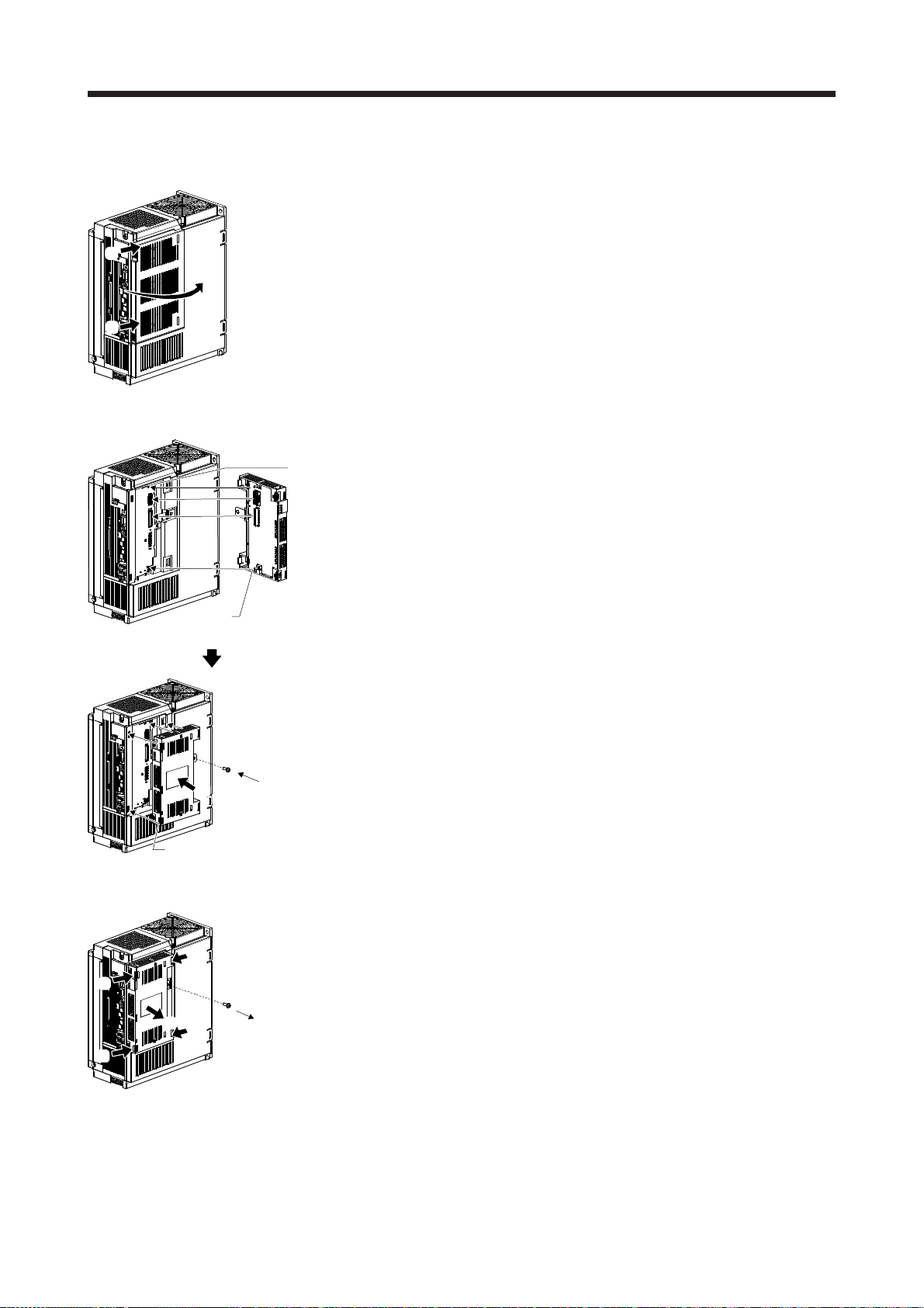
2. INSTALLATION
(2) MR-J4-500_-RJ to MR-J4-700_-RJ/MR-J4-350_4-RJ to MR-J4-700_4-RJ
(a) Detachment of the side cover
1) While pushing the clips ( a) , b)), and pull out the side cover to the arrow
direction.
a)
1)
b)
(b) Attachment of MR-D30
1) Insert the guide pins of the MR-D30 in the guide holes located on the side of
Guide hole
1)
the servo amplifier.
1)
Guide pin
2)
Clip
3)
(c) Detachment of MR-D30
c)
a)
2)
d)
1)
2) To connect the CN7 and CN9 connectors straight, push the four corners of the
MR-D30 against the servo amplifier simultaneously, and keep pushing until the
clips click into place.
3) Tighten the unit with the enclosed mounting screw (M4).
1) Remove the mounting screw.
2) While pushing the clips ( a), b), c), d)), pull out MR-D30 to the arrow direction.
Do not pull the MR-D30 without removing the mounting screw.
b)
2 - 7

2. INSTALLATION
(d) Attachment of the side cover
a)
1)
1)
Side cover setting clip
1) Insert the side cover setting clips into the recesses a) of the servo amplifier.
2) Push the side cover at the supporting point a) in procedure 1) until the clips clip
into place.
2)
Clip
(3) MR-J4-11K_-RJ to MR-J4-22K_-RJ, and drive units of 30 kW or more
Avoid touching burr remained after the part a) being cut off from the case shown
CAUTION
in the figure below. Otherwise, it may cause injury.
The mounting screw hole on these servo amplifiers are covered and not shown at shipping. When
attaching the unit for the first time, cut off the part a) from the case after removing the side cover.
When cutting off the part a), be careful not to damage the case of the servo amplifier. After the part a) is
cut off, inside of the servo amplifier will be exposed even after the side cover or the unit is attached.
Prevent foreign materials from entering through the opened area into the servo amplifier.
For attaching and detaching the unit, refer to (2) in this section. Attachment and detachment of the cover
is in the same manner as the unit.
a)
2 - 8

3. SIGNALS AND WIRING
3. SIGNALS AND WIRING
Any person who is involved in wiring should be fully competent to do the work.
Before wiring, turn off the power and wait for 15 minutes or more until the charge
lamp of the servo amplifier turns off. Then, confirm that the voltage between P+
and N- is safe with a voltage tester and others. Otherwise, an electric shock may
occur. In addition, when confirming whether the charge lamp is off or not, always
confirm it from the front of the servo amplifier.
WARNING
Ground the servo amplifier and servo motor securely.
Do not attempt to wire the servo amplifier and servo motor until they have been
installed. Otherwise, it may cause an electric shock.
The cables should not be damaged, stressed, loaded, or pinched. Otherwise, it
may cause an electric shock.
To avoid an electric shock, insulate the connections of the power supply
terminals.
Wire the equipment correctly and securely. Otherwise, the servo motor may
operate unexpectedly, resulting in injury.
Connect cables to the correct terminals. Otherwise, a burst, damage, etc. may
occur.
Ensure that polarity (+/-) is correct. Otherwise, a burst, damage, etc. may occur.
The surge absorbing diode installed to the DC relay for control output should be
fitted in the specified direction. Otherwise, the emergency stop and other
protective circuits may not operate.
MR-D30
DO4NB
DO4PB
For sink output interface
24 V DC
RA
MR-D30
Control
output signal
For source output interface
DO24VA/
DO24VB/
DO4PA
24 V DC
RA
CAUTION
Use a noise filter, etc. to minimize the influence of electromagnetic interference.
Electromagnetic interference may be given to the electronic equipment used near
the servo amplifier.
Do not install a power capacitor, surge killer or radio noise filter (optional FR-BIF(H)) with the power line of the servo motor.
When using a regenerative resistor, switch power off with the alarm signal.
Otherwise, a transistor fault or the like may overheat the regenerative resistor,
causing a fire.
Do not modify the equipment.
Connect the servo amplifier power output (U/V/W) to the servo motor power input
(U/V/W) directly. Do not let a magnetic contactor, etc. intervene. Otherwise, it may
cause a malfunction.
Servo amplifier
U
V
W
Servo motor
U
V
W
Servo motorServo amplifier
U
M
V
W
U
V
W
3 - 1
M

3. SIGNALS AND WIRING
Connecting a servo motor of the wrong axis to U, V, W, or CN2 of the servo
amplifier may cause a malfunction.
CAUTION
For signals and wiring of servo amplifiers, refer to each servo amplifier instruction manual.
Before wiring, switch operation, etc., eliminate static electricity. Otherwise, it may
cause a malfunction.
POINT
The following indicate hardware abbreviations (H/W abbreviation) of the
connector pin No., not functions.
H/W
abbreviation
DI1A CN10A-4 DO1A CN10A-8
DI2A CN10A-13 DO2A CN10A-17
DI3A CN10A-5 DO3A CN10A-9
DI4A CN10A-14 DO4NA CN10A-18
DI5A CN10A-6 DO1B CN10B-8
DI6A CN10A-15 DO2B CN10B-17
DI1B CN10B-4 DO3B CN10B-9
DI2B CN10B-13 DO4PB CN10B-16
DI3B CN10B-5
DI4B CN10B-14
DI5B CN10B-6
DI6B CN10B-15
Pin No.
H/W
abbreviation
Pin No.
3 - 2

3. SIGNALS AND WIRING
3.1 Connectors and pin assignment
The servo amplifier front view shown is an example of the MR-J4-20B-RJ or less. Refer to section 4.4.1 for
functions that can be assigned to DI1_ to DI6_, and section 4.4.2 for DO1_ to DO4_.
For connectors other than CN10A/CN10B, refer to each servo amplifier instruction manual.
CN10A (Note)
No. Symbol Symbol No.
CN8
Remove the short-circuit
connector.
10 DC24VA DC24VA
11 DICOMA DICOMA 2
12 PLSA 3
13 DI2A DI1A 4
14 DI4A DI3A 5
15 DI6A DI5A 6
16 7
DO4PA
17 DO2A DO1A 8
18 DO3A 9
DO4NA
CN10B (Note)
No. Symbol Symbol No.
10 DC24VB DC24VB
11 DICOMB DICOMB 2
12 PLSB 3
13 DI2B DI1B 4
14 DI4B DI3B 5
15 DI6B DI5B 6
16 7
DO4PB
17 DO2B DO1B 8
18 DO3B 9
DO4NB
DO24VA
DO24VB
1
1
Note. DO4PA (CN10A-16), DO4NA (CN10A-18), DO4PB (CN10B-16), and DO4NB (CN10B-18) are not supported by MR-D30
manufactured in September, 2014 or earlier. Do not connect anything to the pins.
3 - 3

3. SIGNALS AND WIRING
A
3.2 I/O signal connection example
Consider 15 ms or shorter delay time from input (DI1A to DI6A and DI1B to DI6B) to output (DO1A to DO4A
and DO1B to DO4B) when connecting cascade.
For connection examples of servo amplifiers, refer to each servo amplifier instruction manual.
3.2.1 Input signal
(Note 1, 2)
10 m or less
24 V DC (Note 3)
10 m or less
DICOMA
DICOMA
DI1A
DI3A
DI4A
DI5A
DI6A
MR-D30
CN10A
2
11
4
13DI2A
5
14
6
15
(Note 1, 2)
10 m or less
24 V DC (Note 3)
10 m or less
DICOMA
DICOMA
DI1A
DI3A
DI4A
DI5A
DI6A
MR-D30
CN10A
2
11
4
13DI2A
5
14
6
15
24 V DC (Note 3)
(Note 1, 2)
For source input interface For sink input interface
Note 1. Separate all the external wires by two types, CN10A and CN10B.
2.
ssign each input device to the following combinations of connector and pin. For details of each device, refer to section 4.4.1
and 4.4.2.
DICOMB
DICOMB
DI1B
DI3B
DI4B
DI5B
DI6B
CN10B
2
11
4
13DI2B
5
14
6
15
Servo amplifier
(Note 1, 2)
24 V DC (Note 3)
DICOMB
DICOMB
DI1B
DI3B
DI4B
DI5B
DI6B
CN10B
2
11
4
13DI2B
5
14
6
15
Servo amplifier
Combination of connector and pin for input
DI1A (CN10A-4)/DI1B (CN10B-4)
DI2A (CN10A-13)/DI2B (CN10B-13)
DI3A (CN10A-5)/DI3B (CN10B-5)
DI4A (CN10A-14)/DI4B (CN10B-14)
DI5A (CN10A-6)/DI5B (CN10B-6)
DI6A (CN10A-15)/DI6B (CN10B-15)
3. Supply 24 V DC ± 10% to interfaces from outside. When all the I/O points are used, the required current capacity is 0.8 A in
total. The current capacity can be decreased by reducing the number of I/O points. Refer to section 3.3 that gives the current
value necessary for the interface. The illustration of the 24 V DC power supply is divided between input signal and output
signal for convenience. However, they can be configured by one.
3 - 4

3. SIGNALS AND WIRING
A
3.2.2 Output signal
DO1A to DO3A, DO1B to DO3B, and DO4NA can be used as source output. DO4PB can be used as sink
output.
MR-D30
(Note 4)
(Note 4)
CN10A
7
8 DO1A
17 DO2A
9 DO3A
16
18 DO4NA
CN10B
7
8 DO1B
17 DO2B
9 DO3B
10 m or less
DO24VA
DO4PA
10 m or less
DO24VB
24 V DC (Note 3)
RA1
RA2
RA3
24 V DC (Note 3)
RA4
24 V DC (Note 3)
RA5
RA6
RA7
Source output
(Note 1, 2)
Source output
(Note 1, 2)
Source output
(Note 1, 2)
(Note 4)
(Note 4)
16 DO4PB
18 DO4NB
RA8
Sink output
(Note 1, 2)
24 V DC (Note 3)
Servo amplifier
Note 1. Separate all the external wires by two types, CN10A and CN10B. Be sure to wire them separately by the two types for power
supply for IO (24 V DC, 0 V common). Do not mix them when wiring.
2.
ssign each output device to the following combinations of connector and pin. For details of each device, refer to section 4.4.1
and 4.4.2.
Combination of connector and pin for output
DO1A (CN10A-8)/DO1B (CN10B-8)
DO2A (CN10A-17)/DO2B (CN10B-17)
DO3A (CN10A-9)/DO3B (CN10B-9)
DO4NA (CN10A-18)/DO4PB (CN10B-16)
3. Supply 24 V DC ± 10% to interfaces from outside. When all the I/O points are used, the required current capacity is 0.8 A in
total. The current capacity can be decreased by reducing the number of I/O points. Refer to section 3.3 that gives the current
value necessary for the interface. The illustration of the 24 V DC power supply is divided between input signal and output
signal for convenience. However, they can be configured by one.
4. DO4PA (CN10A-16), DO4NA (CN10A-18), DO4PB (CN10B-16), and DO4NB (CN10B-18) are not supported by MR-D30
manufactured in September, 2014 or earlier. Do not connect anything to the pins.
3 - 5

3. SIGNALS AND WIRING
3.3 Connection of I/O interface
The following shows a connection of I/O interface. Refer to this section and make connection with an
external device.
3.3.1 Source output
This is an input circuit in which the anode of the photocoupler is the input terminal. Transmit signals from
source (open collector) type transistor output, relay switch, etc.
The wiring differs depending on a device to be connected, and on whether or not a test pulse diagnosis is
executed. Refer to section 4.4.1 for the test pulse diagnosis. (Rated current: 5 mA, maximum current: 10
mA)
(1) Connection of external device
Connect the output signal of external device to DI _ _.
MR-D30
CN10A
DICOMA
24 V DC 5 mA
24 V DC
External device
Control
24V IN
output 1
Control
0V IN
output 2
24 V DC 5 mA
(2) Switch connection (not when executing a test pulse diagnosis)
Wire without using PLSA and PLSB.
24 V DC ± 10%
0.8 A
(Test pulse diagnosis disabled)
Switch
DI1A, etc.
Approx. 5.6 kΩ
CN10B
DICOMB
DI1B, etc.
Approx. 5.6 kΩ
CN10A
DICOMA
DI1A, etc.
Approx. 5.6 k
MR-D30
Ω
24 V DC ± 10%
0.8 A
CN10B
DICOMB
DI1B, etc.
Approx. 5.6 k
Ω
3 - 6

3. SIGNALS AND WIRING
(3) Switch connection (when executing a test pulse diagnosis)
The pulses for diagnosis will be outputted from PLSA and PLSB. Wire so that the pulse signals
outputted from PLSA and PLSB pass through the switch.
MR-D30
CN10A
DC24VA
PLSA
DICOMA
DI1A, etc.
Approx. 5.6 kΩ
CN10B
DC24VB
PLSB
DICOMB
DI1B, etc.
Approx. 5.6 kΩ
(Test pulse diagnosis enabled)
Switch
24 V DC ± 10%
0.8 A
24 V DC ± 10%
0.8 A
3.3.2 Sink input
This is an input circuit whose photocoupler cathode side is input terminal. Transmit signals from sink (open
collector) type transistor output, relay switch, etc.
The wiring differs depending on a device to be connected, and on whether or not a test pulse diagnosis is
executed. Refer to section 4.4.1 for the test pulse diagnosis. (Rated current: 5 mA, maximum current: 10
mA)
(1) Connection of external device
Connect the output signal of external device to DI _ _.
MR-D30
CN10A
DICOMA
DI1A, etc.
Approx.
CN210B
DICOMB
DI1B, etc.
Approx. 5.6 k
5.6 k
Ω
Ω
24 V DC
24 V DC 5 mA
External device
Control
24V IN
output 1
Control
0V IN
output 2
24 V DC 5 mA
3 - 7

3. SIGNALS AND WIRING
(2) Switch connection (not when executing a test pulse diagnosis)
Wire without using PLSA and PLSB.
24 V DC ± 10%
0.8 A
(Test pulse diagnosis disabled)
Switch
CN10A
DICOMA
DI1A, etc.
Approx.
MR-D30
5.6 kΩ
24 V DC ± 10%
0.8 A
CN10B
DICOMB
DI1B, etc.
Approx. 5.6 kΩ
(3) Switch connection (when executing a test pulse diagnosis)
The pulses for diagnosis will be outputted from PLSA and PLSB. Wire so that the pulse signals
outputted from PLSA and PLSB pass through the switch.
MR-D30
(Test pulse diagnosis enabled)
Switch
24 V DC ± 10%
0.8 A
24 V DC ± 10%
0.8 A
CN10A
DC24VA
PLSA
DICOMA
DI1A, etc.
Approx.
CN10B
DC24VB
PLSB
5.6 kΩ
DICOMB
DI1B, etc.
Approx. 5.6 kΩ
3 - 8

3. SIGNALS AND WIRING
3.3.3 DO1_ to DO3_ source output
When the output transistor is turned on, the current will flow to the output terminal to a load. A lamp, relay, or
photocoupler can be driven. Install a diode (D) for an inductive load, or install an inrush current suppressing
resistor (R) for a lamp load. (Rated current: 5 mA to 40 mA, maximum current: 50 mA, inrush current: 100
mA or less) A maximum of 2.4 V voltage drop occurs in MR-D30.
MR-D30
CN10A
DO24VA
DO1A to
DO3A
24 V DC ± 10%
0.8 A
(Note)
Load
If polarity of diode is
reversed, MR-D30
will malfunction.
Safety relay
CN10B
DO24VB
DO1B to
DO3B
Note. If polarity of power is reversed, the safety relay may malfunction.
24 V DC ± 10%
0.8 A
(Note)
Load
If polarity of diode is
reversed, MR-D30
will malfunction.
3.3.4 DO4NA source output and DO4NB sink output
DO4NA as source output and DO4PB as sink output can be combined to use. As for DO4NA, when the
output transistor is turned on, the current will flow from the output terminal to a load. As for DO4PB, when the
output transistor is turned on, the current will flow from a load to the output terminal. A lamp, relay, or
photocoupler can be driven. Install a diode (D) for an inductive load, or install an inrush current suppressing
resistor (R) for a lamp load. (Rated current: 5 mA to 40 mA, maximum current: 50 mA, inrush current: 100
mA or less) A maximum of 2.4 V voltage drop occurs in MR-D30.
MR-D30
CN10A
DO4PA
DO4NA
24 V DC ± 10%
0.8 A
(Note)
Load
If polarity of diode is
reversed, MR-D30
will malfunction.
Safety relay
CN10B
DO4PB
DO4NB
Note. If polarity of power is reversed, the safety relay may malfunction.
(Note)
24 V DC ± 10%
0.8 A
Load
If polarity of diode is
reversed, MR-D30
will malfunction.
3 - 9

3. SIGNALS AND WIRING
r
3.4 Wiring for SBC output
POINT
This function guarantees only that power to mechanical brake is properly
supplied, and abrasion of the brake cannot be detected. Check this function
regularly that the mechanical brake can operate.
SBCS (SBC output) can be used by being connected to the electromagnetic brake on the servo motor. Wire
it so that the electromagnetic brake operates when SBCS (SBC output) turns off. Using MBR of servo
amplifier (electromagnetic brake interlock) is not necessary.
Refer to section 4.5.6 for the operation sequence for when using SBC function.
Servo amplifie
MR-D30
CN10A
DO24VA
SBCS
CN10B
DO24VB
SBCS
Note 1. Create the circuit in order to shut off by being interlocked with the emergency stop switch.
2. Do not use the 24 V DC interface power supply for the electromagnetic brake.
24 V DC
RA1
RA2
RA1
24 V DC (Note 2)
RA2
ALM
(Malfunction)
(Note 1)
U
Servo motor
B1
B
B2
3 - 10

3. SIGNALS AND WIRING
t
3.5 Noise reduction techniques
(1) Grounding shield of shielded cable
The following show measures against malfunctions of MR-D30 and servo amplifier for when the MR-D30
is installed near a device which generates excessive noise.
Ground a shield of the shielded cable near the MR-D30, and be careful that the cable after grounding
should not be affected by electromagnetic induction of the cable before grounding.
Partly remove the insulator of the shielded cable, and ground the exposed shielded part by making
contact in a large area with the cabinet. You can also use clamp metal parts as shown in figure 3.2.
Mask the painted internal wall of the cabinet that touches the clamp metal parts.
Screw
Shielded par
Masked paint part
Figure 3.1 The shielded part to be exposed Figure 3.2 Grounding shields
Ground the shield of the signal input cable as close as possible (30 cm or less) to the MR-D30.
MR-D30
Inside the cabinet
AD75CK
30 cm or less
Clamp fitting
Shielded cable
3 - 11
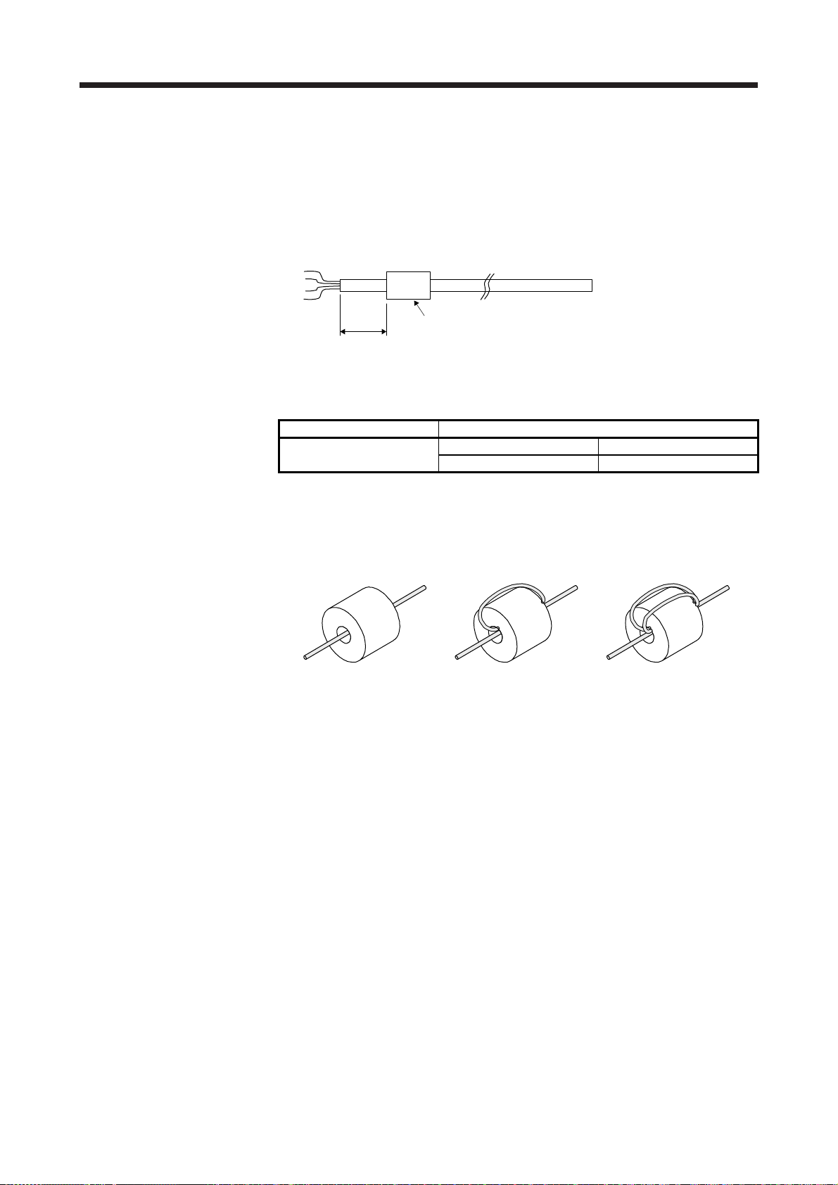
3. SIGNALS AND WIRING
(2) Ferrite core
A ferrite core has the effect of reducing conduction noise in the band around 10 MHz and radiated noise
in the bands between 30 MHz to 100 MHz. When the shield effect of the shielded cable drawn out from
the cabinet is not obtained enough or when emission of conduction noise from a power supply line
should be suppressed, we recommend that you install the ferrite core.
Install the ferrite core at the position of the cable shown in the following figure. If the installation position
is incorrect, the ferrite core will not be effective.
Ferrite core
120 mm or less
Installing ferrite cores to the signal input wires and cables will suppress more noise. The following table
lists a ferrite core as an example.
Model Impedance [Ω] (Note)
ZCAT3035-1330 (TDK)
10 MHz to 100 MHz 100 MHz to 500 MHz
80 150
Note. The values include wires (reference values) and are not guaranteed values.
ESD-SR-250 (NEC TOKIN), E04SRM563218 (SEIWA ELECTRIC) can also be used.
The effect of noise suppression rises as the number of passes though the ferrite core increases. Two or
more passes are recommended.
One pass Two passes Three passes
3 - 12

3. SIGNALS AND WIRING
3.6 Signal explanations
3.6.1 Input device
Assign the devices to DI1_ to DI6_ with [Pr. PSD02 Input device selection DI1] to [Pr. PSD07 Input device
selection DI6]. Refer to section 4.4.1 for details.
For the safety observation function control by network, you can input through network.
Device Symbol
STO
command
SS1
command
SS2
command
SLS1
command
SLS2
command
SLS3
command
SLS4
command
Test pulse
output A
Test pulse
output B
STOC CN10A-4
SS1C The SS1 function operates by the SS1 command. Refer to section 4.5.2
SS2C The SS2/SOS functions operate by the SS2 command. Refer to section
SLS1C The SLS function 1 operates by the SLS1 command. [Pr. PSA07 SLS
SLS2C The SLS function 2 operates by the SLS2 command. [Pr. PSA08 SLS
SLS3C The SLS function 3 operates by the SLS3 command. [Pr. PSA09 SLS
SLS4C The SLS function 4 operates by the SLS4 command. [Pr. PSA10 SLS
PLSA CN10A-12 Outputs test pulses for external wiring diagnosis.
PLSB CN10B-12 Outputs test pulses for external wiring diagnosis.
Connector and pin
No.
CN10A-5
CN10A-6
CN10A-13
CN10A-14
CN10A-15
CN10B-4
CN10B-5
CN10B-6
CN10B-13
CN10B-14
CN10B-15
Function
The STO function operates by the STO command. Refer to section
4.5.1 for details of the STO function.
for details of the SS1 function.
4.5.3 for details of the SS1 function.
deceleration monitoring time 1] and [Pr. PSA11 SLS speed 1] are used.
Refer to section 4.5.4 for details of the SLS function.
deceleration monitoring time 2] and [Pr. PSA12 SLS speed 2] are used.
Refer to section 4.5.4 for details of the SLS function.
deceleration monitoring time 3] and [Pr. PSA13 SLS speed 3] are used.
Refer to section 4.5.4 for details of the SLS function.
deceleration monitoring time 4] and [Pr. PSA14 SLS speed 4] are used.
Refer to section 4.5.4 for details of the SLS function.
Status of
input pin
when the
function is
enabled
Open
Open
Open
Open
Open
Open
Open
3 - 13

3. SIGNALS AND WIRING
3.6.2 Output device
The status monitor (SM) of the safety observation function is outputted from the devices of DO1_ to DO4_.
The devices can be assigned to DO1_ to DO4_ with [Pr. PSD08 Output device selection DO1] to [Pr. PSD11
Output device selection DO4]. Refer to section 4.4.2 for details. For the safety observation function control
by network, you can output through network. Then, DO1_ to DO4_ can be used simultaneously.
Device Symbol
SSM output SSMS CN10A-8
SBC output SBCS Outputs a control signal of the electromagnetic brake. Refer to section
STO output STOS This is a monitor output signal meaning that the STO function is
SOS output SOSS This is a monitor output signal meaning that the servo motor in stop
SS1 output SS1S This is a monitor output signal meaning that the SS1 function is
SS2 output SS2S This is a monitor output signal meaning that the SS2/SOS function is
SLS1 output SLS1S This is a monitor output signal meaning that the SLS function 1 is
SLS2 output SLS2S This is a monitor output signal meaning that the SLS function 2 is
SLS3 output SLS3S This is a monitor output signal meaning that the SLS function 3 is
SLS4 output SLS4S This is a monitor output signal meaning that the SLS function 4 is
Connector and pin
No.
CN10A-9
CN10A-17
CN10A-18
CN10B-8
CN10B-9
CN10B-17
CN10B-16
Indicates that the servo motor speed is at SLS speed or less while
speed observation is operating by SLS function. Refer to section 4.5.5
for details.
4.5.6 for details.
operating. Refer to section 4.5.1 for details.
state is being monitored with the SS2/SOS functions. Refer to section
4.5.3 for details.
operating. Refer to section 4.5.2 for details.
operating. Refer to section 4.5.3 for details.
operating. Refer to section 4.5.4 for details.
operating. Refer to section 4.5.4 for details.
operating. Refer to section 4.5.4 for details.
operating. Refer to section 4.5.4 for details.
Function
Status of
output pin
during
operation
Closed
Open
Open
Open
Open
Open
Open
Open
Open
Open
3 - 14

3. SIGNALS AND WIRING
3.6.3 Power supply
Name Symbol
Digital input
I/F common
A
Test pulse
power
supply input
A
Digital
output I/F
common A
Digital
output I/F
DO4A
power
supply
Digital input
I/F common
B
Test pulse
power
supply input
B
Digital
output I/F
common B
Digital
output I/F
DO4B
power
supply
DICOMA CN10A-2
DC24VA CN10A-1
DO24VA CN10A-7 This is a common terminal for output signal.
DO4PA CN10A-16 This is a power supply terminal of DO4A output signal. Connect + of 24 V DC external
DICOMB CN10B-2
DC24VB CN10B-1
DO24VB CN10B-7 This is a common terminal for output signal.
DO4NB CN10B-18 This is a power supply terminal of DO4B output signal. Connect - of the 24 V DC
Connector and pin
No.
CN10A-11
CN10A-10
CN10B-11
CN10B-10
Function and application
This is a common terminal for input signal. Input 24 V DC (24 V DC ± 10% 0.8 A) for
I/O interface. The power supply capacity varies depending on the number of I/O
interface points to be used.
For sink interface, connect + of 24 V DC external power supply.
For source interface, connect - of 24 V DC external power supply.
Input a power supply to output test pulses for external wiring diagnosis. Connect + of
the 24 V DC external power supply.
For source interface, connect + of the 24 V DC external power supply.
power supply.
This is a common terminal for input signal. Input 24 V DC (24 V DC ± 10% 0.8 A) for
I/O interface. The power supply capacity varies depending on the number of I/O
interface points to be used.
For sink interface, connect + of 24 V DC external power supply.
For source interface, connect - of 24 V DC external power supply.
Input a power supply to output test pulses for external wiring diagnosis. Connect + of
the 24 V DC external power supply.
For source interface, connect + of the 24 V DC external power supply.
external power supply.
3 - 15

3. SIGNALS AND WIRING
3.7 Wiring method of CN10A/CN10B connectors
When wiring to CN10 and CN10B, use the connector DFMC 1,5/9-STF-3,5 (Phoenix Contact) packed with
the servo amplifier.
(1) Fabricating wire insulator
Use a wire with AWG 24 to 16, and strip the wire end to make the stripped length 10 mm ± 0.5 mm.
(2) Inserting wire
Insert the wire while pressing the release button with a flat-blade screwdriver with a blade width of 2.0
mm to 2.5 mm. When the wire is inserted all the way, remove the screw driver.
It is recommended using the following screwdriver manufactured by Phoenix Contact: model: SZS
0,4X2,5, product No.: 1205037.
Upper row
Lower row
Release button
Wire insertion hole
Flat-blade
screwdriver
Wire
(3) Removing wire
Pull out the wire while pressing the release button with the flat-blade screwdriver.
Remove the screwdriver
to connect.
3 - 16

3. SIGNALS AND WIRING
3.8 Connection example with other devices
3.8.1 MR-J4-_GF_-RJ
(1) Safety observation function control by input device
The following connection diagram shows an operation of the safety observation function using input
devices assigned to pins of the CN10A and CN10B connectors with a safety controller. By diagnosis of
input signals, the servo amplifier complies with safety level Category 4, PL e, SIL 3.
24 V
Safety controller MELSEC-WS series
CPU module WSO-CPU0
Safety I/O combined module WS0-XTIO
I1
WS0-CPU0
A1
(24V)
A2
(0V)
WS0-XTIO
FLEXB
Application
US+
24 V 0 V
FLEXB
US+
Application
A1
(24V)
A2
(0V)
X1
X2
Q1
Q2
Q3
I2
KM1
I3
I4
S1
MR-D30 MR-J4-_GF_-RJ
CN10A
DO24VA
DO_A
CN10B
DO24VB
DO_B
CN10A
DICOMA
DI_A
CN10B
DICOMB
DI_B
CC-Link IE Field
Network
Control circuit
Safety observation function
CN1A
Servo
motor
Controller
0 V
3 - 17
Deceleration
command
QX_
COM
KM1: Magnetic contactor
S1: Safety switch
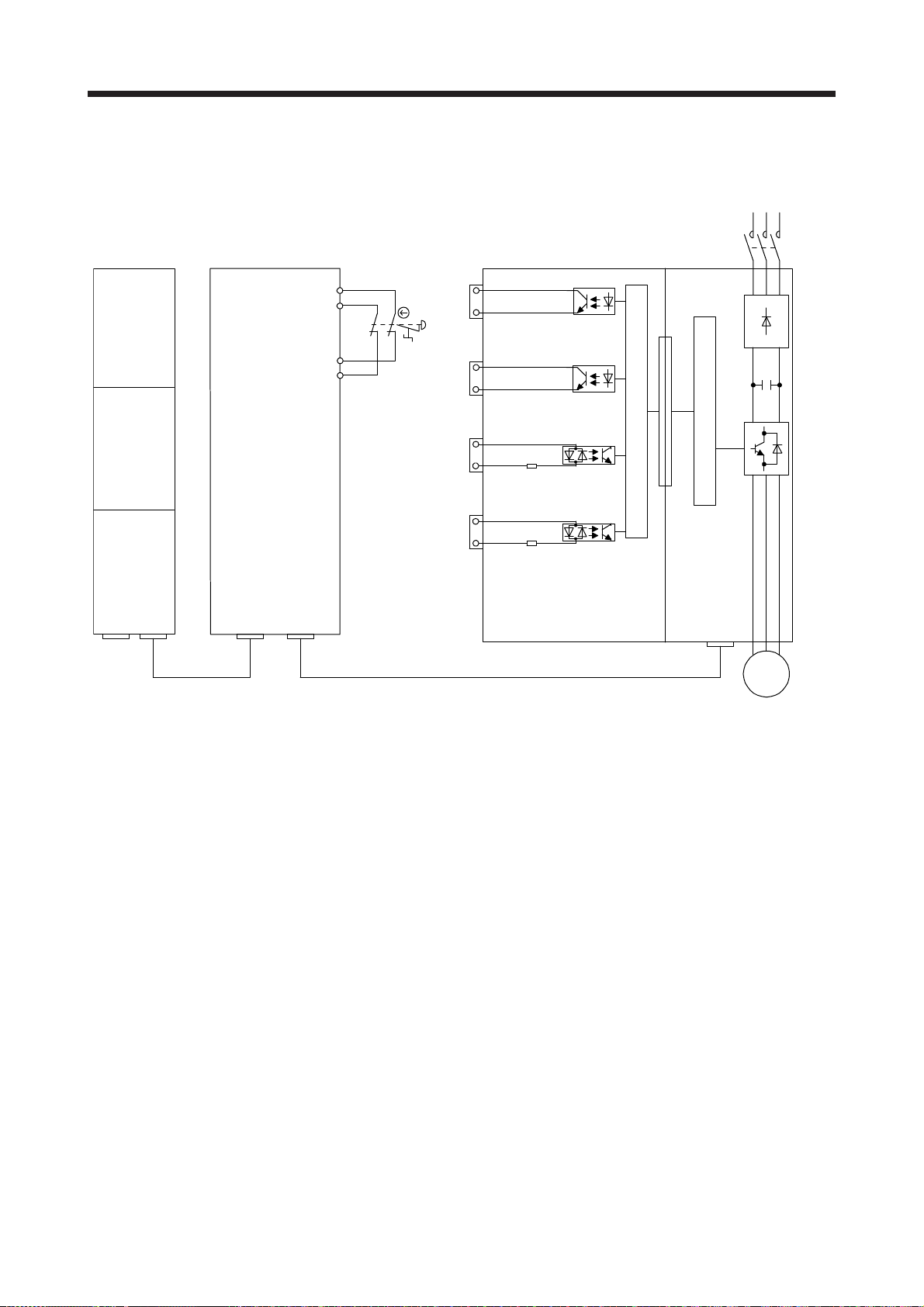
3. SIGNALS AND WIRING
(2) Safety observation function control by network
The following connection diagram shows an operation of the safety observation function through CCLink IE Field Network. The electric wiring can be omitted.
MR-D30 MR-J4-_GF_-RJ
R_SFPU
X0
X1
T0
T1
R6SFM
RD77GF_
CN10A
S1
CN10B
CN10A
CN10B
DO24VA
DOXA
DO24VB
DOXB
DICOMA
DI_A
DICOMB
DI_B
Control circuit
Safety observation function
KM1
NZ2GFSS2-32D
P1/P2 P1/P2
CC-Link IE Field Network
CN1A
CN1B
KM1: Magnetic contactor
S1: Safety switch
Servo
motor
3 - 18

3. SIGNALS AND WIRING
3.8.2 MR-J4-_B_-RJ/MR-J4-DU_B_-RJ
(1) Safety observation function control by input device
The following connection diagram shows an operation of the safety observation function using input
devices assigned to pins of the CN10A and CN10B connectors with a safety controller. By diagnosis of
input signals, the servo amplifier complies with safety level Category 4, PL e, SIL 3.
24 V
Safety controller MELSEC-WS series
CPU module WSO-CPU0
Safety I/O combined module WS0-XTIO
I1
0 V
WS0-CPU0
A1
(24V)
A2
(0V)
WS0-XTIO
FLEXB
Application
US+
24 V 0 V
FLEXB
US+
Application
A1
(24V)
Q1
Q2
Q3
A2
(0V)
X1
X2
I2
MR-J4-_B_-RJ/
MR-J4-DU_B_-RJ
Safety observation function
CN1A
SSCNET III/H
CN1/2
Servo system
Deceleration
command
X00
COM
KM1: Magnetic contactor
S1: Safety switch
Control circuit
controller
CN10A
CN10B
CN10A
CN10B
MR-D30
DO24VA
DO_A
DO24VB
DO_B
DICOMA
DI_A
DICOMB
DI_B
I3
I4
S1
KM1
Servo
motor
IO unit
QX_
3 - 19

3. SIGNALS AND WIRING
(2) Safety observation function control by network
The following connection diagram shows an operation of the safety observation function through
SSCNET III/H. The electric wiring can be omitted.
Drive safety integrated motion controller
Motion controller Q17_DSCPU
Safety signal module Q173DSXY
Q173DSCPU
Q172DSCPU
CN1/2
or
Q173DSXY
SSCNET III/H
MC-X01
PLC-X01
COM
CN10A
S1
CN10B
CN10A
CN10B
MR-D30 MR-J4-_B_-RJ
DO24VA
DOXA
DO24VB
DOXB
DICOMA
DI_A
Safety observation function
DICOMB
DI_B
Control circuit
CN1A
KM1: Magnetic contactor
S1: Safety switch
Servo
motor
KM1
3 - 20

3. SIGNALS AND WIRING
3.8.3 MR-J4-_A_-RJ/MR-J4-DU_A_-RJ
The following connection diagram shows an operation of the safety observation function using input devices
assigned to pins of the CN10A and CN10B connectors with a safety controller. By diagnosis of input signals,
the servo amplifier complies with safety level Category 4, PL e, SIL 3.
24 V
Safety controller MELSEC-WS series
CPU module WSO-CPU0
Safety I/O combined module WS0-XTIO
I1
WS0-CPU0
A1
(24V)
A2
(0V)
WS0-XTIO
FLEXB
Application
US+
24 V 0 V
FLEXB
US+
Application
A1
(24V)
Q1
Q2
Q3
A2
(0V)
X1
X2
I2
Servo
motor
KM1
MR-J4-_A_-RJ/
MR-J4-DU_A_-RJ
Control circuit
Safety observation function
CN1A
General-purpose
interface
CN1/2
DIO control
CN10A
CN10B
CN10A
CN10B
MR-D30
DO24VA
DO_A
DO24VB
DO_B
DICOMA
DI_A
DICOMB
DI_B
I3
I4
S1
0 V
3 - 21
Deceleration
command
QX_
COM
KM1: Magnetic contactor
S1: Safety switch

3. SIGNALS AND WIRING
3.9 Power-on sequence
Maintain about 0.5 s to 2 s in addition to the startup time of the servo amplifier in the system using MR-D30
and servo motor with functional safety for the initial diagnosis of the encoder.
3 - 22

4. SAFETY OBSERVATION FUNCTION
4. SAFETY OBSERVATION FUNCTION
POINT
The following indicate hardware abbreviations (H/W abbreviation) of the
connector pin No., not functions.
DI1A CN10A-4 DO1A CN10A-8
DI2A CN10A-13 DO2A CN10A-17
DI3A CN10A-5 DO3A CN10A-9
DI4A CN10A-14 DO4NA CN10A-18
DI5A CN10A-6 DO1B CN10B-8
DI6A CN10A-15 DO2B CN10B-17
DI1B CN10B-4 DO3B CN10B-9
DI2B CN10B-13 DO4PB CN10B-16
DI3B CN10B-5
DI4B CN10B-14
DI5B CN10B-6
DI6B CN10B-15
H/W
abbreviation
Pin No.
H/W
abbreviation
Pin No.
4 - 1

4. SAFETY OBSERVATION FUNCTION
4.1 Achievable safety level
The achievable safety level and usable safety observation function depend on devices to be connected.
Note that parameters need to be set according to the devices connected. The following shows servo motors
and parameter settings required to meet each functional safety level.
(1) Shut off/Observation function
(a) Safety observation function control by network (CC-Link IE Field Network)
Category 4, PL e, SIL 3 Category 3, PL d, SIL 2 Not required _ _ 0 1 (no execution)
Category 4, PL e, SIL 3 Category 4, PL e, SIL 3 Category 4, PL e, SIL 3 Required _ _ 1 1 (execution)
(b) Safety observation function control by network (SSCNETIII/H)
Category 3, PL d, SIL 2 Category 3, PL d, SIL 2 Not required _ _ 0 1 (no execution)
Category 3, PL d, SIL 2 Category 3, PL d, SIL 2 Category 3, PL d, SIL 2 Required _ _ 1 1 (execution)
(c) Safety observation function control by input device
STO function
SS1 function
Category 3,
PL d, SIL 2
Category 4,
PL e, SIL 3
Category 3,
PL d, SIL 2
Category 4,
PL e, SIL 3
Category 3,
PL d, SIL 2
Category 4,
PL e, SIL 3
Note 1. Set the IO diagnosis pulses of the controller to disabled (not use).
2. Set the IO diagnosis pulses of the controller to enabled (use). The controller needs to be compatible with SIL 3.
Safety observation function Connected device Parameter setting
STO function
SS1 function
Safety observation function Connected device Parameter setting
STO function
SS1 function
Safety observation function Connected device Parameter setting
SLS function
Category 3,
PL d, SIL 2
Category 3,
PL d, SIL 2
Category 4,
PL e, SIL 3
SLS function SS2/SOS function
SLS function SS2/SOS function
SS2/SOS
function
Category 3,
PL d, SIL 2
Category 4,
PL e, SIL 3
Device to be connected to the input
devices (DI1_ to DI6_) (example)
Emergency stop push button, safety
switch, enable switch
Safety programmable controller (Note
1), safety controller (Note 1)
Emergency stop push button, safety
switch, enable switch
Safety programmable controller (Note
2), safety controller (Note 2)
Emergency stop push button, safety
switch, enable switch
Safety programmable controller (Note
1), safety controller (Note 1)
Emergency stop push button, safety
switch, enable switch
Safety programmable controller (Note
2), safety controller (Note 2)
Emergency stop push button, safety
switch, enable switch
Safety programmable controller (Note
1), safety controller (Note 1)
Emergency stop push button, safety
switch, enable switch
Safety programmable controller (Note
2), safety controller (Note 2)
Servo motor with functional
Servo motor with functional
Servo motor
with functional
Not required
Not required
Not required
Not required
Not required
Not required
Not required
Not required
Required
Required
Required
Required
safety
safety
safety
Position/speed
observation
Pr. PSA02
_ _ 0 0
(no execution)
_ _ 0 0
(no execution)
_ _ 0 0
(no execution)
_ _ 0 0
(no execution)
_ _ 2 0
(execution)
_ _ 2 0
(execution)
_ _ 2 0
(execution)
_ _ 2 0
(execution)
_ _ 1 0
(execution)
_ _ 1 0
(execution)
_ _ 1 0
(execution)
_ _ 1 0
(execution)
Position/speed observation
Pr. PSA02
Position/speed observation
Pr. PSA02
Built-in test
pulse
diagnosis
Pr. PSD24
Pr. PSD25
0
(no execution)
0
(no execution)
1
(execution)
0
(no execution)
0
(no execution)
0
(no execution)
1
(execution)
0
(no execution)
0
(no execution)
0
(no execution)
1
(execution)
0
(no execution)
Fixing-
diagnosis at
start-up
Pr. PSD27
Pr. PSD28
1
(execution)
1
(execution)
1
(execution)
0
(no execution)
1
(execution)
1
(execution)
1
(execution)
0
(no execution)
1
(execution)
1
(execution)
1
(execution)
0
(no execution)
4 - 2

4. SAFETY OBSERVATION FUNCTION
(2) Output function
SSM function Status monitor function (STO/SS1/SBC)
SSMS
Category 3,
PL d, SIL 2
Category 3,
PL d, SIL 2
Category 4,
PL e, SIL 3
Note 1. Set the IO diagnosis pulses on the controller side (compatible with SIL 3) to disabled (not use).
2. Set the IO diagnosis pulses on the controller side (compatible with SIL 3) to enabled (use).
3. It is recommended checking (diagnosing) if the output devices operates correctly at least once in 24 hours.
4.2 Safety diagnosis function list
Safety observation function Connected device Parameter setting
Position/speed
observation
_ _ 0 0
(no execution)
_ _ 0 1
(no execution)
_ _ 0 0
(no execution)
_ _ 0 0
(no execution)
_ _ 2 0
(execution)
_ _ 2 1
(execution)
_ _ 2 0
(execution)
_ _ 2 0
(execution)
_ _ 1 0
(execution)
_ _ 1 0
(execution)
_ _ 1 0
(execution)
STOS/SS1S/
SBCS
Category 3,
PL d, SIL 2
Category 4,
PL e, SIL 3
Category 3,
PL d, SIL 2
Category 4,
PL e, SIL 3
Category 3,
PL d, SIL 2
Category 4,
PL e, SIL 3
SLS1S/SLS2S/
SLS3S/SLS4S
Category 3,
PL d, SIL 2
Category 3,
PL d, SIL 2
Category 4,
PL e, SIL 3
Device to be connected to the output
SOSS/SS2S Pr. PSA02 Pr. PSD29
Category 3,
PL d, SIL 2
Category 4,
PL e, SIL 3
devices (DO1_ to DO4_) (example)
Magnetic contactor, safety relay Not required
Drive safety integrated motion
controller, magnetic contactor, safety
relay
Safety programmable controller (Note
1), safety controller (Note 1)
Safety programmable controller (Note
2), safety controller (Note 2)
Magnetic contactor, safety relay Not required
Drive safety integrated motion
controller, magnetic contactor, safety
relay
Safety programmable controller (Note
1), safety controller (Note 1)
Safety programmable controller (Note
2), safety controller (Note 2)
Magnetic contactor, safety relay Required
Safety programmable controller (Note
1), safety controller (Note 1)
Safety programmable controller (Note
2), safety controller (Note 2)
Servo motor
with functional
safety
Not required
Not required
Not required
Not required
Not required
Not required
Required
Required
Built-in test
pulse
diagnosis
0
(no execution)
(Note 3)
0
(no execution)
(Note 3)
1
(execution)
0
(no execution)
(Note 3)
0
(no execution)
(Note 3)
0
(no execution)
(Note 3)
1
(execution)
0
(no execution)
(Note 3)
0
(no execution)
(Note 3)
1
(execution)
0
(no execution)
Diagnosis item Description
I/O device Duplication input mismatch
detection
Input device test pulse
diagnosis
Output device test pulse
diagnosis
Safety device fixing diagnosis
at start-up
This function diagnoses that the duplicated input device states are matched.
This function diagnoses that the input circuit and the externally connected machine
are not fixed to on.
This function diagnoses that the output circuit and the externally connected
machine are not fixed to on.
This function diagnoses that input devices are not fixed by repeatedly turning the
devices on and off individually when the power to MR-D30 is switched on.
4 - 3

4. SAFETY OBSERVATION FUNCTION
4.3 Startup
4.3.1 Switching power on for the first time
POINT
The following symbols mean respective servo amplifier instruction manuals.
[GF]: MR-J4-_GF_(-RJ) Servo Amplifier Instruction Manual (Motion Mode)
[B]: MR-J4-_B(-RJ) Servo Amplifier Instruction Manual
[A]: MR-J4-_A(-RJ) Servo Amplifier Instruction Manual
[Motion]: Q173D(S)CPU/Q172D(S)CPU Motion Controller Programming Manual
The password is set for MR-D30 to prevent changing the parameters. The initial
password is "000000".
(Safety Observation)
4 - 4

4. SAFETY OBSERVATION FUNCTION
When switching power on for the first time, follow this section to make a startup.
"[GF]" means "MR-J4-_GF_(-RJ) Servo Amplifier Instruction Manual (Motion Mode)". "[B]" means "MR-J4_B_(-RJ) Servo Amplifier Instruction Manual". "[A]" means "MR-J4-_A_(-RJ) Servo Amplifier Instruction
Manual".
Wiring check of servo amplifier
Wiring check of MR-D30
Surrounding environment check
Wiring/preparation
Startup of servo amplifier
Parameter setting (actual operation)
Parameter check
Safety observation function
activation setting
Test operation of the servo motor
alone in test operation mode
Cancellation of STO by inputting
Test operation of the servo motor
STO command
alone by commands
Test operation with the servo
motor and machine connected
Gain adjustment
Password setting
Parameter inspection
Check whether the servo amplifier and servo motor are wired
correctly using visual inspection, DO forced output function, etc.
Check whether MR-D30 is wired correctly using visual inspection,
DO forced output function, etc.
Check the surrounding environment of the servo amplifier and servo
motor.
Set the parameters of the servo amplifier as necessary, such as
operation mode and regenerative option selection.
Confirm the combination of MR-D30 and servo amplifier, then
enable the MR-D30 referring to section 4.3.3.
The password is set for MR-D30 to prevent changing the
parameters. The initial password is "000000".
In the test operation, operate the servo motor at the lowest speed
possible, with the servo motor disconnected from the machine, and
check whether the servo motor rotates correctly.
Cancel STO state by a controller or an input signal.
For the safety observation function control by input device, refer to
section 4.4.1.
For the safety observation function control by network, for MR-J4-
_GF_-RJ, refer to section 4.4.3 (2) (3) (4). For MR-J4-_B_-RJ, refer
to section 2.9.1 of "Q173D(S)CPU/Q172D(S)CPU Motion Controller
Programming Manual (Safety Observation)".
As necessary, set MR-D30 parameters.
In the test operation, operate the servo motor at the lowest speed
possible by giving commands to the servo amplifier, with the servo
motor disconnected from the machine, and check whether the servo
motor rotates correctly.
Connect the servo motor with the machine, and check machine
motions by giving operation commands from the controller.
Make gain adjustment to optimize the machine motions. [GF]: Chapter 6
Set the parameters of MR-D30.
Lock the safety observation function parameter 1 ([Pr. PSA_ _ ]) by
password to prevent easily changing the settings.
Read the each parameter to verify that the parameter is set correctly.
Description Reference
[GF]: Section 4.5
[B]: Section 4.5.1
[A]: Section 4.5.8
Section 4.3.4 (2)
[GF]: Section 4.1
[B]: Section 4.1.3
[A]: Section 4.1.3
[GF]: Chapter 5
[B]: Chapter 5
[A]: Chapter 5
Section 4.3.3
Section 4.3.4
[GF]: Section 4.5
[B]: Section 4.5
[A]: Section 4.2.3
Section 4.3.3
Section 4.4.3
Section 4.4.1
Section 4.4.3 (2),
(3), (4)
[Motion]: Section
2.9.1
[B]: Chapter 6
[A]: Chapter 6
Chapter 5
Section 4.3.2 (2)
Startup of safety
observation function
Operation check of safety
observation function
Actual operation
Stop
Check if the safety observation function operates correctly.
Stop giving commands and stop operation.
4 - 5

4. SAFETY OBSERVATION FUNCTION
4.3.2 Parameter
When using MR-D30, the safety observation function parameters 1 ([Pr. PSA_ _ ]), network parameters ([Pr.
PSC_ _ ]) and I/O device parameters ([Pr. PSD_ _ ]) can be set by using MR Configurator2.
Execute the setting that involves safety observation function by these parameter groups. The following
shows the difference between these and other parameter groups. The password is set to MR-D30 to prevent
changing the parameters. The default password is "000000".
(a) Set a password to prevent easily changing the parameter settings of MR-D30.
(b) After the settings are changed, the power needs to be cycled.
(c) After changing the settings, follow the procedure to check if the parameters are correct.
(d) The parameter settings of MR-D30 cannot be stored in the Motion controller or safety programmable
controller.
(e) Set the parameters of MR-D30 with MR Configurator2.
(f) The parameters of MR-D30 cannot be set with the parameter unit.
4 - 6

4. SAFETY OBSERVATION FUNCTION
(1) Parameter setting procedure
Set the parameter by the procedure as follows.
Connection to MR Configurator2
Parameter setting
Parameter inspection
Cycling of power
(2) Protection by password.
Set a password to the safety observation function parameters 1 ([Pr. PSA_ _ ]), network parameters
([Pr. PSC_ _ ]), and I/O device parameters ([Pr. PSD_ _ ]) to prevent changing them easily. There are
no restrictions for reading parameters when a password is set. However, changing parameter is
restricted until the password is confirmed.
(a) Setting and changing password
Connection to MR Configurator2
Password setting
Cycling of power
(b) If password is forgotten
The password is forgotten, you can reconfigure the parameter settings by initializing MR-D30.
Initialize the password by the password initializing function of MR Configurator2. When the password
is initialized, all the parameter setting values will be initialized. [AL. 7A Parameter setting error
(safety observation function)] occurs until the parameter is set again.
Set the parameter with MR Configurator2 connected. When the parameter
protection is set, input the password.
Set the each parameter.
Read the each parameter and check if the parameter is set correctly.
The set parameter will be enabled after the power is cycled.
To set and change a password, connect MR Configurator2. When the
parameter protection is set, input the password.
Set a password with MR Configurator2. Set a password using one to six
digits alphanumeric. The password is case sensitive and letter case matters.
The set password will be valid after the power is cycled.
4 - 7

4. SAFETY OBSERVATION FUNCTION
4.3.3 Mandatory parameter setting
(1) Safety observation function control by input device
(2) Safety observation function control by network
(a) MR-J4-_GF_-RJ
(b) MR-J4-_B_-RJ
(3) Details of parameters
(a) [Pr. PSA01 Safety observation function activation setting]
Check the contents of [Pr. PSA _ _ ], [Pr. PSC _ _ ], and [Pr. PSD _ _ ] and set [Pr. PSA01 Safety
observation function activation setting] to "_ _ _ 1". Until this parameter is set, STO cannot be
canceled due to [AL. 7A Parameter setting error (safety observation function)] occurrence.
(b) [Pr. PSA02 Functional safety unit setting]
Set the items according to your system configuration. The recommended parameter settings and
achievable safety level differ by the system structure. Refer to section 4.1 for details.
(c) [Pr. PSA03 SS1/SS2 monitoring deceleration time]
The parameter for SS1 function must be set because the function will be used when an error is
detected by self-diagnosis. Set a proper value referring to section 4.5.2.
(d) [Pr. PSC01 Safety communication - Communication cycle]
Set the communication cycle of SSCNET III/H or CC-Link IE Field Network. For MR-J4-_B_-RJ, set
the same value as of the controller to "Safety communication - Communication cycle". When a
different value is set, [AL. 7C.1 Functional safety unit communication setting error (safety
observation function)] will occur.
(e) [Pr. PSC04 Safety communication - Network communication selection]
Set the network number of CC-Link IE Field Network. Match the network number of the master
station with that of MR-J4_-GF_-RJ. Otherwise, [AL. 95.4 STO warning 2 (safety observation
function)] will occur.
Parameter Name
PSA01 Safety observation function activation setting
PSA02 Functional safety unit setting
PSA03 SS1/SS2 monitoring deceleration time
Parameter Name
PSA01 Safety observation function activation setting
PSA02 Functional safety unit setting
PSA03 SS1/SS2 monitoring deceleration time
PSC01 Safety communication - Communication cycle
PSC04 Safety communication - Network communication selection
Parameter Name
PSA01 Safety observation function activation setting
PSA02 Functional safety unit setting
PSA03 SS1/SS2 monitoring deceleration time
PSC01 Safety communication - Communication cycle
4 - 8

4. SAFETY OBSERVATION FUNCTION
4.3.4 Test operation
(1) Summary
When using MR-D30, parameter setting is necessary for using the test operation. Set [Pr. PSA02
Functional safety unit setting] to "_ _ _ 2". The diagnosis function and safety observation function are
partially disabled in the test operation mode. The mode can be used for the JOG operation, positioning
operation, machine analyzer, etc. for when the startup of safety devices is not complete. Note the
following for test operation mode.
(a) Set the test operation mode. For details of the test operation mode, refer to each servo amplifier
(2) DO forced output
4.3.5 Unit replacement
instruction manual.
(b) I/O will not be diagnosed.
(c) Operate with great care because the safety observation function is disabled.
(d) If the servo motor operates abnormally, use EM2 (Forced stop 2) to stop it.
For details of the test operation, refer to each servo amplifier instruction manual.
To stop the test operation, set [Pr. PSA02 Functional safety unit setting] to "_ _ _ 0" or "_ _ _ 1"
according to your system configuration, and cycle the power.
Output signals of DO1_ to DO4_ can be switched on/off forcibly and independently regardless of servo
status. This function is used to check the wirings of signal output, etc. Exercise control on the DO forced
output screen of MR Configurator2.
This function can be used only when [Pr. PSA02 Functional safety unit setting] is set to "_ _ _ 2" (test
operation mode).
When an MR-D30 that has already been attached to MR-J4-_-RJ servo amplifier once is attached to the
other MR-J4-_-RJ servo amplifier, [AL. 7A Parameter setting error (safety observation function)] will occur.
To use the MR-D30 with other MR-J4-_-RJ servo amplifier, initialize the password by the password
initializing function of MR Configurator2. When the password is initialized, all the parameters will be
initialized. [AL. 7A Parameter setting error (safety observation function)] occurs until the parameters are set
again.
4.4 I/O function
4.4.1 Input device
(1) Summary
For the safety observation function control by network, input devices cannot be used. The input devices
of MR-D30 have the following characteristics.
(a) Input device selection
Any device can be assigned to DI1_ to DI6_ with parameters.
(b) Duplication of the input wiring
The input error will be detected immediately by verifying input signals with duplicated wirings.
4 - 9

4. SAFETY OBSERVATION FUNCTION
(c) Fixing-diagnosis at start-up
The input devices including the external wiring are diagnosed for failure by individually being turned
on and off repeatedly when the power is switched on. Enabled/disabled can be switched with [Pr.
(2) Input device selection
PSD27] and [Pr. PSD28].
(d) Diagnosis with test pulses
The input devices including the external wiring are diagnosed for failure by using pulse signals that
temporarily turns off the input signals when the input signals are on. Enabled/disabled can be
selected with [Pr. PSD24] and [Pr. PSD25].
Set any test pulse width considering the wiring length of the external circuit, impedance of the circuit,
etc. If the pulse width is not enough, change the test pulse off-time with [Pr. PSD26 Input device Test pulse off time].
(e) Noise rejection filter
This function is to reduce the noise to input signals.
(a) Input device selection
The input devices can be assigned to DI1_ to DI6_ with [Pr. PSD02 Input device selection DI1] to
[Pr. PSD07 Input device selection DI6].
CN10A CN10B
Pin No.
4 DI1A 4 DI1B [Pr. PSD02 Input device selection DI1]
13 DI2A 13 DI2B [Pr. PSD03 Input device selection DI2]
5 DI3A 5 DI3B [Pr. PSD04 Input device selection DI3]
14 DI4A 14 DI4B [Pr. PSD05 Input device selection DI4]
6 DI5A 6 DI5B [Pr. PSD06 Input device selection DI5]
15 DI6A 15 DI6B [Pr. PSD07 Input device selection DI6]
H/W
abbreviation
Pin No.
H/W
abbreviation
For details of each input device, refer to the following section. Note that one input device cannot be
assigned to multiple connector pins of the same connector.
Input signal Reference
STOC (STO command) Section 4.5.1
SS1C (SS1 command) Section 4.5.2
SS2C (SS2 command) Section 4.5.3
SLS1C (SLS1 command)
SLS2C (SLS2 command)
SLS3C (SLS3 command)
SLS4C (SLS4 command)
Section 4.5.4
(b) Input device automatic activation selection
Setting [Pr. PSD01 Input device automatic activation selection] activates operation command of each
function automatically. The automatically activated input device will be enabled regardless of input
device condition, and the corresponding function will operate automatically.
SLS1C (SLS1 command), SLS2C (SLS2 command), SLS3C (SLS3 command), and SLS4C (SLS4
command) can be automatically activated.
Parameter
4 - 10

4. SAFETY OBSERVATION FUNCTION
(3) Duplication of the input wiring
(a) Duplication of the input wiring
Switch DI_A and DI_B within the mismatch permissible time.
This function continuously monitors whether signals of duplicated input are matched. The
corresponding input device will be processed as off when a mismatch is detected. The following
shows the operation sequence when SLS1C (SLS1 command) is assigned to DI1. SLS1C (SLS1
command) is off while DI1A and DI1B are mismatched. SLS1C (SLS1 command) is on when both
DI1A and DI1B turn on. When the mismatch continues exceeding the mismatch permissible time
specified by the parameter, [AL. 79.7 Mismatched input signal error] occurs and SS1 function
operates.
An error will not occur when the
mismatch time is within
the permissible time.
DI1A
ON
OFF
Input device
Mismatch permissible time
DI1B
SLS1C
(SLS1 command)
Servo amplifier
display
ON
OFF
ON (disabled)
OFF (enabled)
No display
Normal
operation
SLS in progress SS1 in progressSLS in progressOperation status
(b) Parameter setting
For the input devices that are assigned by [Pr. PSD02 Input device selection DI1] to [Pr. PSD07
Input device selection DI6], set the following parameters. Setting the mismatch permissible time to 0
disables the diagnosis.
Parameter Name
PSD18 Mismatch permissible time DI1
PSD19 Mismatch permissible time DI2
PSD20 Mismatch permissible time DI3
PSD21 Mismatch permissible time DI4
PSD22 Mismatch permissible time DI5
PSD23 Mismatch permissible time DI6
(4) Fixing-diagnosis at start-up
This function diagnoses that each input pin has no failure by repeatedly turning the signals on and off
when the power to MR-D30 is switched on.
79.7
4 - 11

4. SAFETY OBSERVATION FUNCTION
(a) Executing fixing-diagnosis at start-up
This function diagnoses a fixing by turning each of DI1_ to DI6_ on, off and on one by one. When all
diagnoses are completed, a warning will be reset, and STO state will be canceled. Keep the pins not
to be diagnosed to on.
The following pins are diagnosed: pins to which functions are assigned with [Pr. PSD02 Input device
selection DI1] to [Pr. PSD07 Input device selection DI6], and in which [Pr. PSD27 Input device Fixing-diagnosis execution selection 1 at start-up] and [Pr. PSD28 Input device - Fixing-diagnosis
execution selection 2 at start-up] are set to "execute".
Additionally, the diagnosis will not be executed to the pin (unused pin) to which an input device is not
assigned with [Pr. PSD02 Input device selection DI1] to [Pr. PSD07 Input device selection DI6].
50 ms
or more
4 s or more
Main circuit
Control circuit
DI1A
DI1B
DI2A
DI2B
DI3A
DI3B
DI4A
DI4B
DI5A
DI5B
DI6A
DI6B
WNG (Warning)
STOS (STO output)
Servo-on
(Controller or DI)
Base circuit
Servo amplifier display
Power
supply
ON
OFF
ON
OFF
ON
OFF
ON
OFF
ON
OFF
ON
OFF
ON
OFF
ON
OFF
ON
OFF
ON
OFF
ON
OFF
ON
OFF
ON
OFF
ON
(Occurring)
OFF
(Not occurring)
ON
OFF
(Shut-off)
ON
OFF
ON
OFF
50 ms
or more
95.3Initialization No alarm
Start of Servo-on acceptance
95 ms
(Enabled)
(Enabled)
(Enabled)
(Unused)
(Diagnosis
disabled)
(Diagnosis
disabled)
4 - 12

4. SAFETY OBSERVATION FUNCTION
(b) Not executing fixing-diagnosis at start-up
If there is no device for the fixing-diagnosis at start-up, an internal diagnosis is executed after poweron. Then, the warning will be reset when all input devices turn on, and the STO state will be
canceled.
Start of servo-on acceptance
3 s to 4 s
Main circuit
Control circuit
DI1A
DI1B
DI2A
DI2B
Power
supply
ON
OFF
ON
OFF
ON
OFF
ON
OFF
ON
OFF
(Diagnosis
disabled)
(Diagnosis
disabled)
DI3A
DI3B
DI4A
DI4B
DI5A
DI5B
DI6A
DI6B
WNG (Warning)
STOS (STO output)
Servo-on
(Controller or DI)
Base circuit
Servo amplifier display
ON
OFF
ON
OFF
ON
OFF
ON
OFF
ON
OFF
ON
OFF
ON
OFF
ON
OFF
ON
(Occurring)
OFF
(Not occurring)
ON
OFF
(Shut-off)
ON
OFF
ON
OFF
95.3
95 ms
(Diagnosis
disabled)
(Unused)
(Diagnosis
disabled)
(Diagnosis
disabled)
4 - 13

4. SAFETY OBSERVATION FUNCTION
(c) Parameter setting
For the pins to which input devices are assigned with [Pr. PSD02 Input device selection DI1] to [Pr.
PSD07 Input device selection DI6] , set whether or not to execute the fixing-diagnosis at start-up with
[Pr. PSD27 Input device - Fixing-diagnosis execution selection 1 at start-up] and [Pr. PSD28 Input
device - Fixing-diagnosis execution selection 2 at start-up].
The achievable safety level will depend on the settings of [Pr. PSD27] and [Pr. PSD28]. Refer to
section 4.1 for details.
(5) Diagnosis with test pulses
(a) When connecting a device which does not have a diagnosis function (such as switch)
The external wirings can be diagnosed by using the pulse signals outputted from PLSA and PLSB.
Refer to section 3.3, and check that the wiring is properly connected to execute the test pulse
diagnosis.
The following shows the operation sequence to execute the test pulse diagnosis by the switch
connected to DI1A and DI1B. The off-pulses are outputted from PLSA/PLSB periodically. PLSA and
PLSB output the off-pulses at different timing, not the same time. The width of off-pulses can be set
with [Pr. PSD26 Input device test pulse off time]. Set the parameter so that external devices such as
switches are affected by the output pulses.
Input device - Test pulse off time
Input device - Test pulse off time
PLSA
PLSB
ON
OFF
ON
OFF
Closed
Switch
DI1A
DI1B
Opened
ON
OFF
ON
OFF
[AL. 79.5 Input device error] occurs when an error is detected by the test pulse diagnosis.
Whether or not the test pulse diagnosis is executed to each input device can be set with [Pr. PSD24
Input device - Test pulse diagnosis execution selection 1] and [Pr. PSD25 Input device - Test pulse
diagnosis execution selection 2].
(b) When connecting a device which has a diagnosis function (such as safety controller)
To diagnose external wiring, use diagnosis function of the device. The test pulse diagnosis of MRD30 cannot be used. Set the relevant device settings to "0" (not diagnose) with [Pr. PSD24 Input
device - Test pulse diagnosis execution selection 1] and [Pr. PSD25 Input device - Test pulse
diagnosis execution selection 2].
4 - 14

4. SAFETY OBSERVATION FUNCTION
(c) Cautions for executing test pulse diagnosis by multiple devices.
When there are multiple input devices for the test pulse diagnosis, share PLSA/PLSB with those
input devices. A short-circuit failure between wirings sharing PLSA/PLSB cannot be detected with
the test pulse diagnosis. Execute the input device fixing-diagnosis at start-up (refer to section 4.4.1
(4)) in addition.
Switch
Switch
24 V DC
Shorted
MR-D30
CN10A
DC24VA
PLSA
DICOMA
DI1A
DI2A
CN10B
DC24VB
(d) Parameter setting
Set the following parameters for DI1_ to DI6_ which input devices are assigned to with [Pr. PSD02
Input device selection DI1] to [Pr. PSD07 Input device selection DI6].
Select whether or not to execute the test pulse diagnosis with [Pr. PSD24 Input device - Test pulse
diagnosis execution selection 1] and [Pr. PSD25 Input device - Test pulse diagnosis execution
selection 2]. Set the off-time of test pulses outputted from PLSA and PLSB to [Pr. PSD26 Input
device - Test pulse off time].
The achievable safety level depends on the input devices you use and parameter settings of this
function. Refer to section 4.1 for details.
24 V DC
Parameter Name
PSD24 Input device - Test pulse diagnosis execution selection 1
PSD25 Input device - Test pulse diagnosis execution selection 2
PSD26 Input device - Test pulse off time
PLSB
DICOMB
DI1B
DI2B
4 - 15

4. SAFETY OBSERVATION FUNCTION
(6) Noise rejection filter
(a) Summary
The noise rejection filter is a function to set a filtering time to reduce the noise of input signals. Set
the filtering time of the noise rejection filter with [Pr. PSD12 Input device - Noise rejection filtering
time DI1] to [Pr. PSD17 Input device - Noise rejection filtering time DI6].
The longer the noise rejection filtering time, the higher the tolerance to chattering or noise, but the
response to the input signals will be lower. The shorter the noise rejection filtering time, the higher
the response to the input signals, but the tolerance to chattering or noise will be lower.
When the test pulses are in superposition in the input signals, the noise rejection filtering time needs
to be set considering the test pulse off-time. The following shows the specific settings of the noise
Using a switch
Using a device
rejection filtering time.
Structure Noise rejection filtering time
Executing a test pulse diagnosis
Not executing a test pulse diagnosis Set 0.888 ms or longer time.
Test pulses are in superposition in the output
signal of the device.
Test pulses are not in superposition in the
output signal of the device.
(b) Parameter setting
With the following parameters, set the noise rejection filtering time to each input device to which
function is assigned with [Pr. PSD02 Input device selection DI1] to [Pr. PSD07 Input device selection
DI6]. In addition, refer to section 4.4.1 (7) because the response time of the input device changes
depending on the noise rejection filtering time.
Parameter Name
PSD12 Input device - Noise rejection filtering time DI1
PSD13 Input device - Noise rejection filtering time DI2
PSD14 Input device - Noise rejection filtering time DI3
PSD15 Input device - Noise rejection filtering time DI4
PSD16 Input device - Noise rejection filtering time DI5
PSD17 Input device - Noise rejection filtering time DI6
Set 0.888 ms or longer time than set time in [Pr. PSD26 Input
device - Test pulse off time].
Set 0.888 ms or longer time than the test pulse off-time
outputted from the device.
Set 0.888 ms or longer time.
4 - 16

4. SAFETY OBSERVATION FUNCTION
(7) Response time of input device
The response time of input devices changes depending on noise rejection filtering time set with [Pr.
PSD12 Input device - Noise rejection filtering time DI1] to [Pr. PSD17 Input device - Noise rejection
filtering time DI6].
The following example shows a sequence for when STOC (STO command) is assigned to DI1_. A delay
equal to the input device noise rejection filtering time occurs in the response time from signals are
inputted to input devices until the corresponding functions switch to enabled/disabled.
DI1A
Input device - Noise rejection
ON
OFF
filtering time
DI1B
STOC
(STO command)
Base circuit
(Energy supply to
the servo motor)
STOS (STO output)
ON
OFF
ON (disabled)
OFF (enabled)
ON
OFF
ON (disabled)
OFF (enabled)
4 - 17

4. SAFETY OBSERVATION FUNCTION
4.4.2 Output device
(1) Summary
The output device of the status monitor function (SM) of MR-D30 has following characteristics.
(a) Output device selection
(2) Output device selection
Any device can be assigned to DO1_ to DO4_ with parameters.
(b) Duplication of the output
Same signal is duplicately outputted by duplicated wiring. With this, a function will not be lost even if
an error occurs in one output device.
DO4_ can be configured with source output and sink output in combination.
(c) Diagnosis with test pulses
The output devices including the external wiring are diagnosed for failure by using pulse signals that
temporarily turns off the output signals when the output signals are on. Enabled/disabled can be
selected with [Pr. PSD29 Output device - Test pulse execution selection].
The devices can be assigned to DO1_ to DO4_ with [Pr. PSD08 Output device selection DO1] to [Pr.
PSD11 Output device selection DO4].
CN10A CN10B
Pin No. H/W abbreviation Pin No. H/W abbreviation
8 DO1A 8 DO1B [Pr. PSD08 Output device selection DO1]
17 DO2A 17 DO2B [Pr. PSD09 Output device selection DO2]
9 DO3A 9 DO3B [Pr. PSD10 Output device selection DO3]
18 DO4NA 16 DO4PB [Pr. PSD11 Output device selection DO4]
Parameter
For details of each output device, refer to the following section. For output devices, the same signal can
be assigned to different terminal.
Output signal Reference
STOS (STO output) Section 4.5.1
SS1S (SS1 output) Section 4.5.2
SS2S (SS2 output) Section 4.5.3
SLS1S (SLS1 output) Section 4.5.4
SLS2S (SLS2 output) Section 4.5.4
SLS3S (SLS3 output) Section 4.5.4
SLS4S (SLS4 output) Section 4.5.4
SSMS (SSM output) Section 4.5.5
SOSS (SOS output) Section 4.5.3
SBCS (SBC output) Section 4.5.6
4 - 18
4. SAFETY OBSERVATION FUNCTION
(3) Diagnosis with test pulses
(a) Test pulse diagnosis function
This function diagnoses the wiring by periodically outputting the off-pulses when DO1_ to DO4_ are
on.
The following shows the operation sequence for when STOS (STO output) is assigned to DO1_. The
off-pulses are outputted to DO1A and DO1B periodically when STOS (STO output) is on. DO1A and
DO1B output the off-pulses at different timing, not the same time. The width of off-pulses can be set
with [Pr. PSD30 Output device - Test pulse off time]. Set the parameter so that external devices are
not affected by the outputted off-pulses.
STOS (STO output)
DO1A
DO1B
[AL. 79.6 Output device error] occurs when an error is detected by the test pulse diagnosis. Whether
or not the test pulse diagnosis is executed to each output device can be set with [Pr. PSD29 Output
device - Test pulse execution selection].
(b) Parameter setting
For the output device that is assigned by [Pr. PSD08 Output device selection DO1] to [Pr. PSD11
Output device selection DO4], set the following parameters.
Set whether or not to execute the test pulse diagnosis to each output device with [Pr. PSD29 Output
device - Test pulse execution selection]. Set the off-time of test pulses outputted from the output
devices to [Pr. PSD30 Output device - Test pulse off time].
The achievable safety level depends on the device you use and parameter settings of this function.
Refer to section 4.1 for details.
ON
OFF
ON
OFF
ON
OFF
Parameter Name
PSD29 Output device - Test pulse execution selection
PSD30 Output device - Test pulse off time
Output device - Test pulse off time
Output device - Test pulse off time
4 - 19

4. SAFETY OBSERVATION FUNCTION
(4) Input signal conditions at start-up/error detection
(a) At start-up
The each output device remains off until the diagnosis completes after the MR-D30 is turned on.
After the diagnosis is completed, devices assigned with [Pr. PSD08 Output device selection DO1] to
[Pr. PSD11 Output device selection DO4] will be activated.
The diagnosis completion time differs depending on the safety observation function control by input
device or by network. For the safety observation function control by input device, refer to section
4.4.1 (4). For the safety observation function control by network, refer to section 4.4.3.
Power
supply
ON
OFF
Diagnosing
STOS (STO output)
DO1A
DO1B
DO2A
DO2B
DO3A
DO3B
DO4NA
DO4PB
ON
OFF
ON
OFF
ON
OFF
ON
OFF
ON
OFF
ON
OFF
ON
OFF
ON
OFF
ON
OFF
(b) At error detection
If MR-D30 detects an error and an alarm which disables SSM occurs, the each device turns off.
Refer to chapter 7 for corresponding alarm Nos. If a non-corresponding alarm occurs, assigned
devices will be outputted continuously.
4 - 20

4. SAFETY OBSERVATION FUNCTION
4.4.3 Safety observation function control by input device
(1) Summary
For the safety observation function control by network, input devices cannot be used. The safety
observation function control by network has the following characteristics.
(a) Transmitting each function command input through network
STOC (STO command), SS1C (SS1 command), SS2C (SS2 command), SLS1C (SLS1 command),
SLS2C (SLS2 command), SLS3C (SLS3 command), and SLS4C (SLS4 command) can be
(2) Setting method of CC-Link IE Field Network for MR-J4-_GF_-RJ
transmitted through network.
(b) Feedback for each function output through network
Safety position data of servo motor with functional safety, STOS (STO output), SOSS (SOS output),
SSMS (SSM output), etc. can be transmitted through network.
The following shows function outputs for each bit of the safety data storage device in MR-J4-_GF_RJ.
POINT
For the system profile (CSP+) of MR-J4-_GF_-RJ, use the file version 4 or later.
If the parameters of MR-D30 are not set, "Safety communication activation
setting" cannot be executed by the parameter processing of slave station.
If "Safety communication activation setting" is not selected in the parameter
processing of slave station, "Safety communication setting" of "Application
setting" cannot be set. For "Safety communication setting", refer to chapter 5 of
"MELSEC iQ-R Safety Application Guide".
The setting method of "Safety communication setting" of CC-Link IE Field Network is as follows. For the
descriptions of each window, operation, and controller setting of GX Works3, refer to "MELSEC iQ-R
Safety Application Guide".
4 - 21

4. SAFETY OBSERVATION FUNCTION
(a) Basic settings (network configuration settings)
To perform the safety communication, select "Motion Mode (Safety Communication)" or "IO Mode
(Safety Communication)" for the station-specific mode setting. Set the number of devices for the
RWw/RWr setting as follows:
Motion mode: 52 points I/O mode: 32 points
Select Motion Mode (Safety Communication) or
IO Mode (Safety Communication).
Double-click the icon to start MR Configurator2.
When the I/O mode is used in the safety communication, the first 16 points in the cyclic RWw/RWr
frame are used for the safety communication.
Thus, to assign link device RWwn/RWrn, consider 16 points for offsets.
For RWwn6 (point table No. selection/next station No. selection), add 16 points as offsets and set a
value to RWw (n + 1) 6.
The following shows the number of offsets necessary for each frame.
(b) Position check of safety slave station
The MR-J4-_GF_-RJ and MR-D30 do not support the position check start function for the safety
slave station. Visually check the station number displayed on the 7-segment LED display of each
servo amplifier to ensure that the safety slave station is installed as designed and intended.
Frame name Offsets for safety communication
RWw 16 points
RWr 16 points
RX 0 points
RY 0 points
4 - 22

4. SAFETY OBSERVATION FUNCTION
(c) Parameter setting of slave station
Right-click "MR-J4-GF" in the network configuration diagram, then select "Parameter processing of
slave station".
Select Parameter processing
of slave station
Select "Safety communication activation setting" for the executing process, then click "Execute".
Select Safety communication activation setting
Click Execute
4 - 23

4. SAFETY OBSERVATION FUNCTION
(d) Application setting (Safety communication setting)
Display "Unit selection for safety communication" by selecting "Local Network" to "Communication
Destination" in the safety communication setting window, add "MR-J4-GF", and then "Transmission
interval monitoring time", "Safety Refresh Monitoring Time" and "Safety data Transfer Device
Setting". Change the setting of [Pr. PSC01 Safety communication - Communication cycle] depending
on "Transmission interval monitoring time". When execute the safety communication after setting,
[AL. 95.5] is displayed on the 7-segment LED display of MR-J4-_GF_-RJ. [AL. 95.5] can be
deactivated with STO command/SS1 command on (disable).
(3) Setting methods for transmission interval monitoring time and safety refresh monitoring time of MR-J4-
_GF_-RJ
For the safety observation function control by network, calculate the transmission interval monitoring
time between MR-D30 and CC-Link IE Field Network master module according to the Safety Application
Guide.
Use the following values for safety remote station refresh response time (SRef).
Safety remote station refresh response time 8.0 ms 16.0 ms
Set the safety communication communication cycle according to the following transmission interval
monitoring time. For MR-J4-_GF_-RJ, do not select "_ _ 0 6" (14.2 ms) or "_ _ 0 7" (28.4 ms).
Otherwise, [AL. 7C.1 Functional safety unit communication setting error (safety observation function)]
will occur.
Calculated transmission interval monitoring time
The following shows another value used for calculating safety response time.
Transmission interval monitoring time of MR-D30 Safety communication communication cycle × 1.5
Motion mode I/O mode
Safety communication
communication cycle
16 ms to 24 ms 16 ms "_ _ 1 6"
24 ms to 48 ms 32 ms "_ _ 1 7"
Name Value
[Pr. PSC01]
4 - 24

4. SAFETY OBSERVATION FUNCTION
Calculate the safety refresh monitoring time. For MR-J4-_GF_-RJ, set the safety refresh monitoring time
so that the following equation is satisfied.
Safety refresh monitoring time [ms] ≥ TMact + TMpas + (LS × 2) + SCmst + (SRef/2)
TMact: Transmission interval monitoring time of CC-Link IE Field Network master module [ms]
TMpas: Transmission interval monitoring time of MR-D30 [ms] (= Safety communication communication
cycle [ms] × 1.5)
LS: Link scan time of CC-Link IE Field Network Network [ms], or the calculation cycle of the simple
Motion module [ms] when a simple Motion module is used as the master module.
SCmst: Safety cycle time of CC-Link IE Field Network master module
SRef: Safety remote station refresh response time [ms]
Set the calculated transmission interval monitoring time of CC-Link IE Field Network master module and
the safety refresh monitoring time to the master module.
(4) Safety data storing devices for MR-J4-_GF_-RJ
(a) Function input
Master station → Servo amplifier (SA\n)
The following shows the function inputs for each bit of the safety data storing devices.
Bit Function input Description
0 STO command When the STO command is turned off, the STO function of the servo amplifier operates, and the
power is shut off.
1 SS1 command When the SS1 command is turned off, the SS1 function operates.
2 SS2 command When the SS2 command is turned off, the SS2 function operates.
3
4
5 Unavailable
6
7
8 SLS1 command When the SLS1 command is turned off, the SLS1 function operates.
9 SLS2 command When the SLS2 command is turned off, the SLS2 function operates.
10 SLS3 command When the SLS3 command is turned off, the SLS3 function operates.
11 SLS4 command When the SLS4 command is turned off, the SLS4 function operates.
12
13
14
15
16
17
18
19
20
21
Unavailable
22
23
24
25
26
27
28
29
30
31
4 - 25

4. SAFETY OBSERVATION FUNCTION
(b) Function output
Servo amplifier → Master station (SA\n)
The following shows the function outputs for each bit of the safety data storing devices.
Bit Function output Description
0 STO status When the STO function operates and the power is shut off, the status turns on. The status is off
under other conditions.
1 SSM status When the servo motor rotates at the set SSM speed or less, the status turns on. When the SSM
function is disabled, the status is always off.
2 Unavailable
3 SOS status When the SS2 function activates the SOS function, the status turns on. The status is off under
other conditions.
4
5 Unavailable
6
7 Error status If an error related to the safety communication occurs, the status turns on. The status is off under
other conditions.
8 SLS1 status When the SLS1 function operates, the status turns on. The status is off under other conditions.
9 SLS2 status When the SLS2 function operates, the status turns on. The status is off under other conditions.
10 SLS3 status When the SLS3 function operates, the status turns on. The status is off under other conditions.
11 SLS4 status When the SLS4 function operates, the status turns on. The status is off under other conditions.
12 SS1 status When the SS1 function operates, the status turns on. The status is off under other conditions.
13 SS2 status When the SS2 function operates, the status turns on. The status is off under other conditions.
14
15 Unavailable
16
17 Error status 2 In [Pr. PSA02 Functional safety unit setting], when a command signal is inputted for an
unavailable safety observation function, the status turns on. The status is off under other
conditions.
18 SBC status This is a status signal for the servo motor holding brake. When the STO function operates and a
power supplied to the electromagnetic brake is shut off, the status turns off. The status is on
under other conditions.
19
20
21
22
23
24
25 Unavailable
26
27
28
29
30
31
4 - 26

4. SAFETY OBSERVATION FUNCTION
A
4.4.4 Servo motor with functional safety
Using a servo motor with functional safety enables you to use speed monitoring functions and position
monitoring functions without external encoders for duplication of encoders.
When using a servo motor with functional safety, set [Pr. PSA02 Functional safety unit setting] to "_ _ 1 _".
When not using it, set [Pr. PSA02] to "_ _ 0 _". Refer to section 4.1 for details.
4.4.5 Position feedback fixing diagnosis function
(1) Summary
The position feedback fixing diagnosis function generates [AL. 79.8 Position feedback fixing error] to
make the servo amplifier STO state when position data from the encoder is fixed.
(2) Operation summary
The position feedback fixing diagnosis function will be enabled when the safety observation function is
enabled and moreover the servo amplifier is not in STO state. When a position feedback does not
change for the time set with [Pr. PSA22 Position feedback fixing error detection time], [AL. 79.8 Position
feedback fixing error] occurs and the STO function operates.
Position (P)
Position change: 0 pulse
Stop STO statusRotation
[Pr. PSA22]
Servo motor
position
LM (Malfunction)
STOS (STO output)
ON (no alarm)
OFF (alarm)
ON (disabled)
OFF (enabled)
4 - 27

4. SAFETY OBSERVATION FUNCTION
4.5 Safety observation function
4.5.1 STO function
(1) Summary
This function electronically shuts off power to the servo motor based on an input signal from an external
device (secondary-side output shut-off). This corresponds to stop category 0 of IEC/EN 60204-1. The
STO function is also used for an emergency stop when an error is detected in an internal diagnosis. Use
the STO function while the servo motor stops.
(2) Operation sequence
(a) STOC (STO command)
Turn off STOC (STO command) only when the servo motor stops after servo off. The STO function
will operate when STOC (STO command) is turned off. While STO is in operation, the power to the
servo motor is shut off and the dynamic brake activates. Turning STOC (STO command) back to on
will return to normal operation.
Ordinary operation Ordinary operation
STO status
Servo motor speed
SON (Servo-on)
or
servo-on command
STOC (STO command)
WNG (Warning)
Base circuit (Energy
supply to the servo
motor)
STOS (STO output)
50 r/min
0 r/min
ON
OFF
ON (disabled)
OFF (enabled)
ON (alarm)
OFF (no alarm)
ON
OFF
ON
OFF (shut-off)
4 - 28

4. SAFETY OBSERVATION FUNCTION
A
A
(b) Alarm occurrence
The STO function operates also during alarm occurrence. While STO is in operation, power to the
servo motor is shut off and the dynamic brake activates. For alarms which activate STO, refer to
chapter 7. For returning to normal operation, refer to section 4.5.10.
The timing chart is for STO/DB stop method.
STO statusOrdinary operation
Servo motor speed
LM (Malfunction)
Base circuit (Energy
supply to the servo
motor)
STOS (STO output)
50 r/min
0 r/min
ON (alarm)
OFF (no alarm)
ON
OFF
ON
OFF (shut-off)
(c) STO shut-off during servo motor operation
Turn off STOC (STO command) only when the servo motor stops after servo off. [AL. 63 STO timing
error] occurs if STOC (STO command) is turned off during operation. Use the SS1 function when
decelerating at the same time.
STO statusOrdinary operation
Servo motor speed
50 r/min
0 r/min
STOC
(STO command)
LM (Malfunction)
Base circuit
(Energy supply to
the servo motor)
STOS (STO output)
ON (disabled)
OFF (enabled)
ON (alarm)
OFF (no alarm)
ON
OFF
ON
OFF (shut-off)
(3) Parameter setting
To set the parameters, refer to section 4.3.3. Set the parameters referring to section 4.4.1 when using
the STO function with input devices, and section 4.4.3 when using the STO function in the safety
observation function control by network.
Additionally, when using STOS (STO output) with output devices, refer to 4.4.2 to set parameters.
4 - 29
 Loading...