

Mitsubishi Electric MR-CU375S-W-A, MR-CU375S-W-ANZ, MR-CU375S-ST-ANZ, MR-CU375S-ST-A, MR-CU375SL-W-A Service Manual
...
Changes for the Better
Models
CONTENTS
A………….......Australia
A(NZ)...............New Zealand
1. SPECIFICATIONS....................................................
2. OUTLINES AND DIMENSIONS..................................
3. WIRING DIAGRAM....................................................
4. REFRIGERANT CIRCUIT...........................................
5. NAMES OF THE PARTS...........................................
6. TROUBLE SHOOTING..............................................
6.1 TROUBLE CRITERION OF MAIN PARTS.......
6.2 FUNCTION OF OPERATION PANEL..............
6.3 FLOW CHART OF SELF-CHECK....................
6.4 TEST POINT DIAGRAM OF MAIN CONTROL
BOARD........................................................
7. DISASSEMBLY INSTRUCTIONS...............................
8. PARTS LIST............................................................
1
3
4
6
7
8
8
11
12
15
16
21
MR-CU375S-W-A
MR-CU375S-ST-A
MR-CU375S-W-A(NZ)
MR-CU375S-ST-A(NZ)
MR-CU375SL-W-A
MR-CU375SL-ST-A
MR-CU375SL-W-A(NZ)
MR-CU375SL-ST-A(NZ)
2006
SERVICE MANUAL
NO.SM-RE-0605
MITSUBISHI
ELECTRIC
HOME REFRIGERATORS
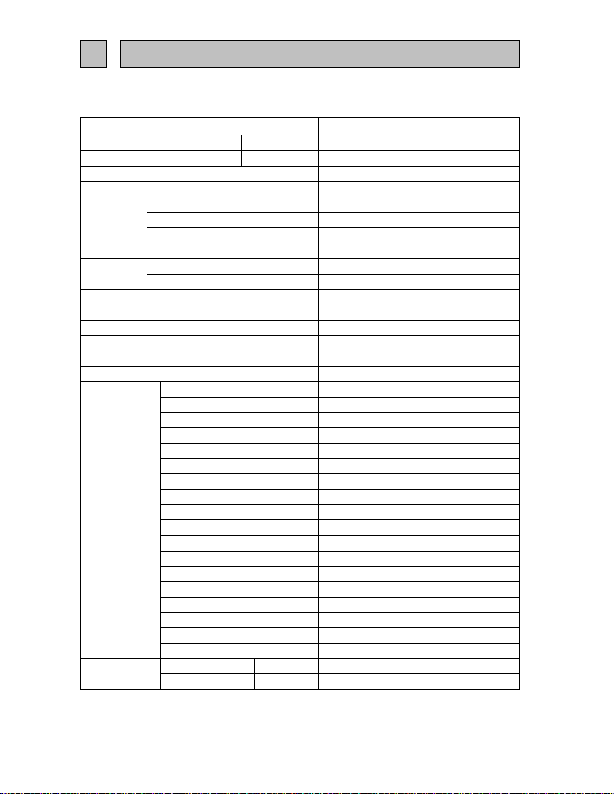
1-1 SPECIFICATIONS
MR-CU375S/SL-A
MR-CU375S/SL-A(NZ)
Power supply
Total capacity L
Dimensions (HXWXD) mm. 1655 x 600 x 639
Cabinet Acrylic resin coated steel
Food liner ABS resin
Cabinet Foamed cyclopenthane
Refrigerator door Foamed cyclopenthane
Vegetable door Foamed cyclopenthane
Freezer door Foamed cyclopenthane
Cooling system
Freezer Forced air convection
Refrigerator 3 way air flow
Evaporator Fin and tube type
Condenser Concealed type
Defrost system Automatic (Defrost heater )
Drain Automatic (drainage)
Temperature control system Automatic control
Refrigerator room light 240V, 15W (E12)
Ice spoon 1 pc.
Slide chilled case (UP) 1 pc.
Slide chilled case (LR) 1 pc.
Freezing case (UP)
1 pc.
Freezing case (LOW)
1 pc.
Crystal shelf (R)
1 pc.
Top plate
1 pc.
Slide shelf
1 pc.
Free pocket (M) 2 pcs.
Tube stand 1 pc.
Egg case 1 pc.
Bottle pocket 1 pc.
Vegetable case 1 pc.
Vegetable case cover
1 pc.
Drain pan 1 pc.
Fruit case 1 pc.
Water tank 1 pc.
Kick plate 1 pc.
Weight
Unit kg 69
Shipping kg 76
1 SPECIFICATIONS
- 1 -
Insulation
Accessories
GROSS (AS) 376 (R : 198 V : 111 F : 67)
230-240V 50Hz
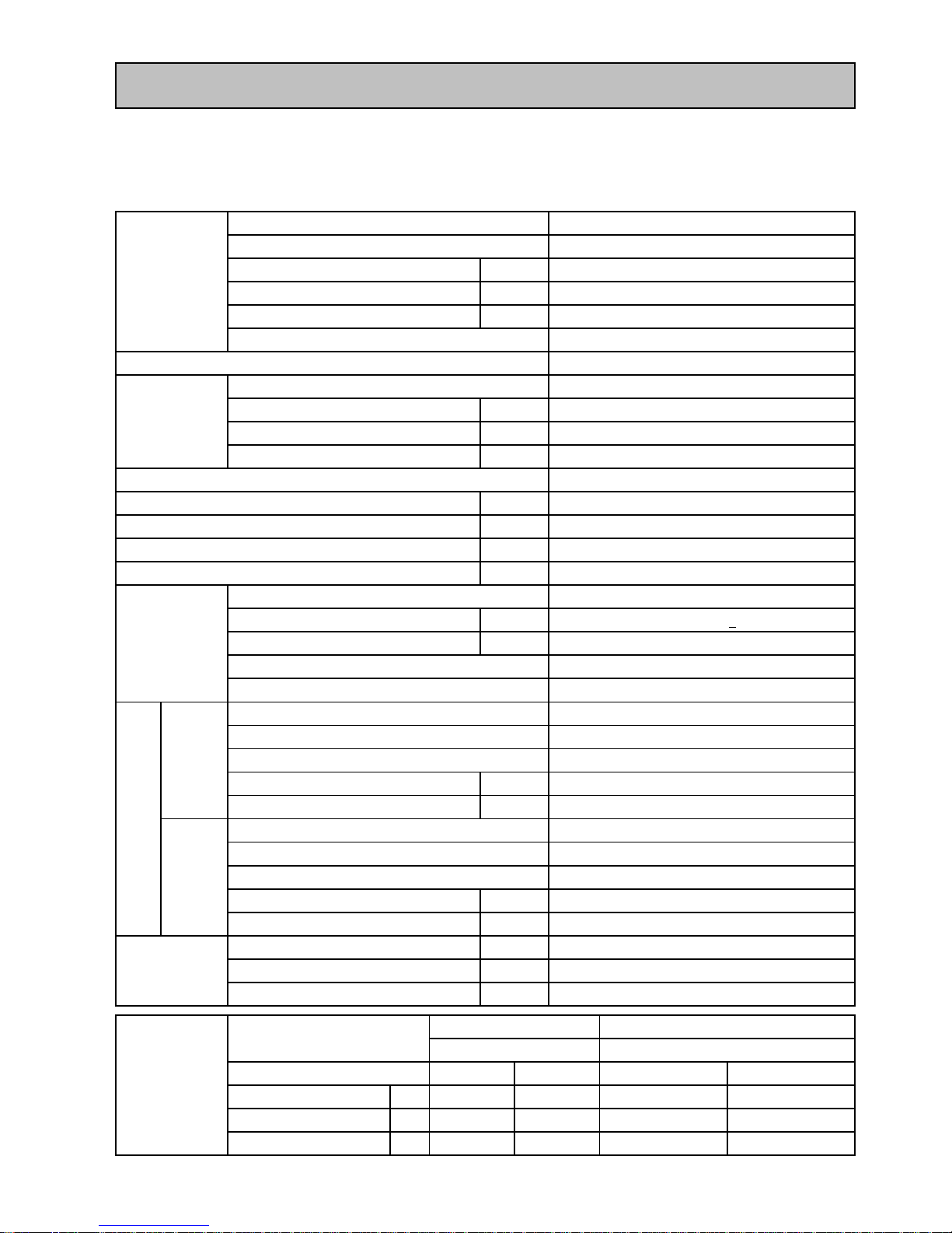
1-2 ELECTRICAL PARTS SPECIFICATION
MR-CU375S/SL-A
MR-CU375S/SL-A(NZ)
Model ESS60C11RAW
Power supply 220-240V, 50Hz
Compresso
r
Rated input W 116/118 (220/240V 50Hz)
Starting current A 8.49/9.31 (220/240V 50Hz)
Running current A 0.57/0.55 (220/240V 50Hz)
Winding resistance (A.T. 20
o
C)
17.9
Ω(Main) / 15.1 Ω(Aux)
PTC RELAY PTH7M330MD2
Model 5TM222NHBYY-53
Motor protecto
r
Ambient temperature
o
C
25
Time Sec. 16 MAX
Current A 6.7
Running capacito
r
4µF 400VAC
Capillary tube mm.
∅ 1.8 X ∅ 0.65 X 2350
Dehydrant Molecular sieve g 10
Refrigerant HFC. 134a g 220
Compressor oil g
Defrosting timer Control board
Defrost finish
o
C
Thermister 14 +
1.5
Thermal fuse
o
C
73
Defrost heater
Not equipped
Model UDQM002B3
Type DC brushless
Number of poles 10P
Input W 2.4 (12V DC)
Revolution r.p.m 1520(12V DC)
Model UDQM004B3
Type DC brushless
Number of poles 10P
Input W 1 (12V DC)
Revolution r.p.m 1200(12V DC)
Vegetable case heate
r
W6
Water pipe heate
r
W0.9
Drain pipe heate
r
W6
Freeze
r
Refrigerato
r
Dial position ON OFF OPEN SHUT
LOW
o
C
-16.0 -21.9 7.0 5.8
MID
o
C
-18.4 -24.3 5.1 3.8
HI
o
C
-21.1 -27.1 3.2 1.9
186 (FREOL ∝ 10)
Refrigerator
384 Ω (240V, 150W)
- 2 -
Defrosting control
Deodorizing function of defrost heater
Thermistor RThermistor F
Fan motor
Heater
Machine
Chamber
Temperature control
MR-CU375S/SL-A
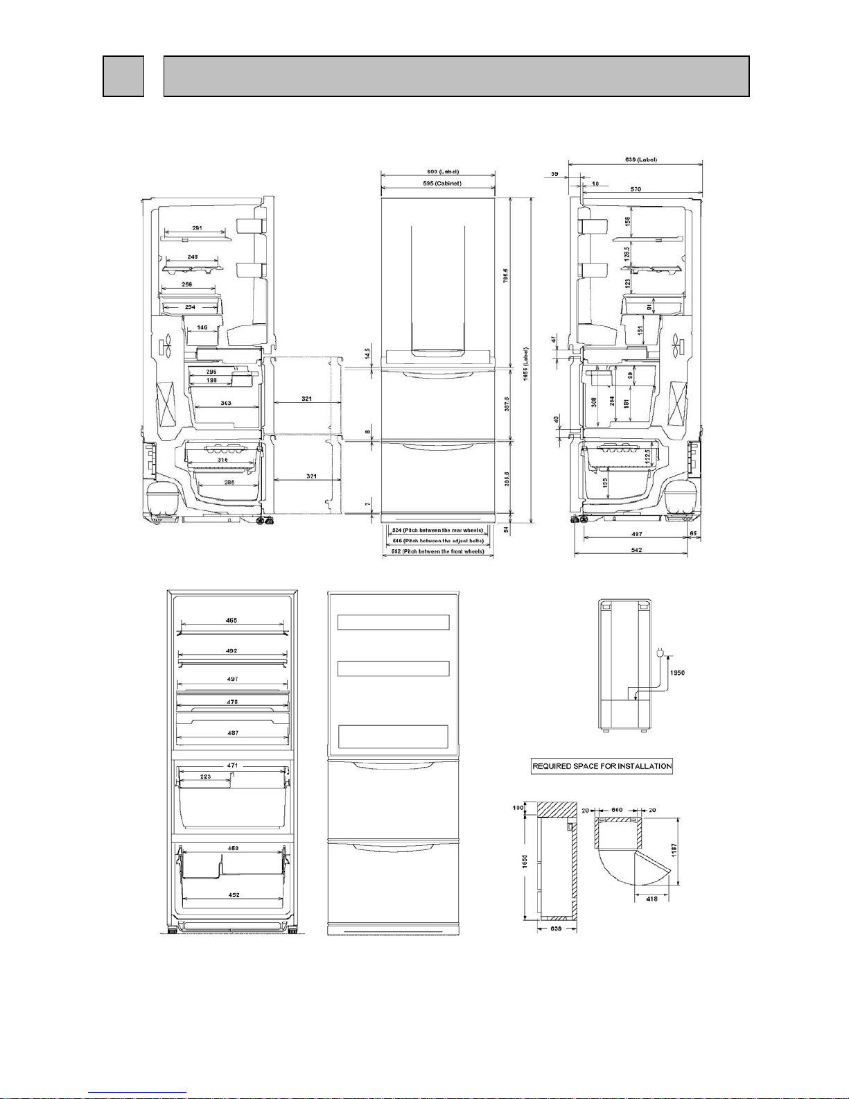
Unit : mm
MR-CU375S/SL-A(NZ)
- 3 -
2 OUTLINES AND DIMENSIONS
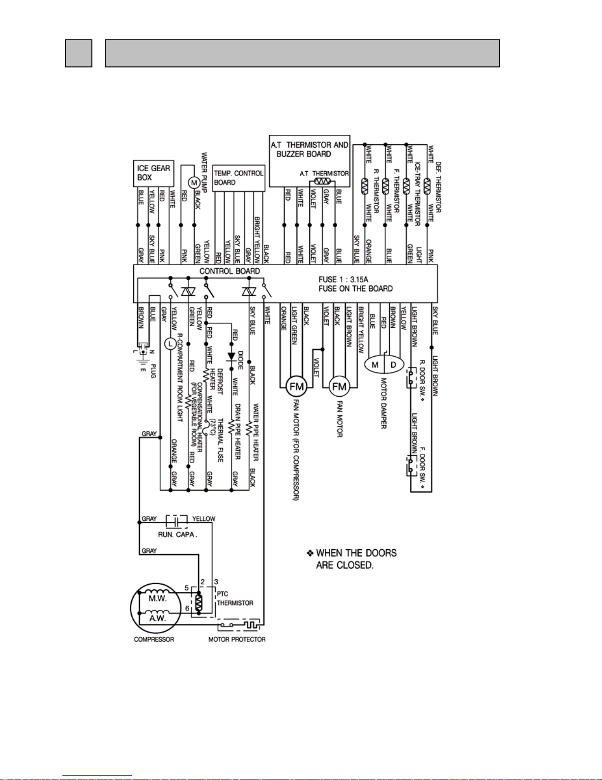
MR-CU375S/SL-A
(SKELETON WIRING DIAGRAM)
MR-CU375S/SL-A(NZ)
3 WIRING DIAGRAM
- 4 -
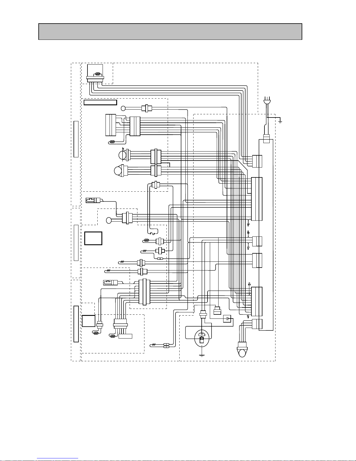
(ACTUAL WIRING DIAGRAM)
Remark GY = GRAY BK = BLACK BR = BROWN
W = WHITE OR = ORANGE
R = RED Y = YELLOW
SB = SKY BLUE YG = YELLOW GREEN
P = PINK LG = LIGHT GREEN
LB = LIGHT BROWN BY = BRIGHT YELLOW
V = VIOLET B = BLUE
- 5 -
THERMALFUSE(73°
7 6 5 4 3 2 1
LL
BUZZER&
THERMISTORA.T
REFRIGERATORROOM
9
8
7
6
5
4
3
2
1
R
Y
SB
GY
BY
BK
8
7
6
5
4
3
2
1
R
Y
SB
GY
BY
BK
W
W
R
Y
SB
GY
BY
BK
OR
SB
THERMISTORR
MOTORDAMPER
MD
1
2
3
4
1
2
3
4
R
Y
B
BR
1
2
3
4
5
6
R
Y
B
BR
R
Y
B
BR
FM
FANMOTOR
BK
V
LB
BY
1
2
3
4
BK
V
LB
BY
BK
V
LB
BY
ROOMLIGHT
1
2
YORY
GY
2
1
GY
W
GY
W
4
3
2
1
1
2
LB
LB
LB
LB
LB
LB
R
B
YG
P
M
WATERPUMP
DOORSW.R
C)
VEGETABLE
ROOM
DEF.THERMISTOR
DEF.HEATER
1
2
1
W
W
W
W
P
SB
R
WATERPIPEHEATER
1
2
1
2
1
2
3
4
5
6
7
8
9
10
1
2
LB
LB
LB
LB
LB
R
GY
R
GY
YG
SBBK
BK
SB
SB
SB
SB
SB
SB
SB
B
B
LG
LG
GY
GY
W
W
P
P
VHEATER
DOORSW.F
FREEZER
ROOM
THERMISTORF
THERMISTORI
GEARBOX
6 5 4 3 2 12 1
DRAIN
HEATER
WW
B
SB
W
GYGY
W
PTC
THERMISTOR
OUTER
FANMOTOR
1 2 3 4
Y
GY
GY
Y
MOTORPROTECTOR
FM
V
BK
OR
LG
4
3
2
1
CN10
12
11
10
9
8
7
6
5
4
3
2
1
V
BK
GY
B
BY
BR
LB
Y
P
R
W
YG
CN4
11
9
7
5
3
1
YG
SB
Y
7
5
3
1
R
W
GY
18
17
16
15
14
13
12
11
10
9
8
7
6
5
4
3
2
1
SB
LB
P
LG
OR
SB
B
Y
R
BY
GY
BK
V
GY
R
W
5
4
3
2
1
3 1
B
BR
CN3
CN2
CN7
CN9
CN1
R
W
V
GY
SB
TEMPCONTROL
W
V
W
V
W
REFRIGERATORDOOR
LG
OR
BK
V
1
2
GY
GY
W
W
2
1
R
DIODE
W
CONTROLBOARD
VEGETABLEDOOR
FREEZERDOOR
W
R
P
SB
YB
W
W
SBLGGY
MR-CU375S/SL-A
MR-CU375S/SL-A(NZ)
MR-CU375S/SL-A
MR-CU375S/SL-A(NZ)
- 6 -
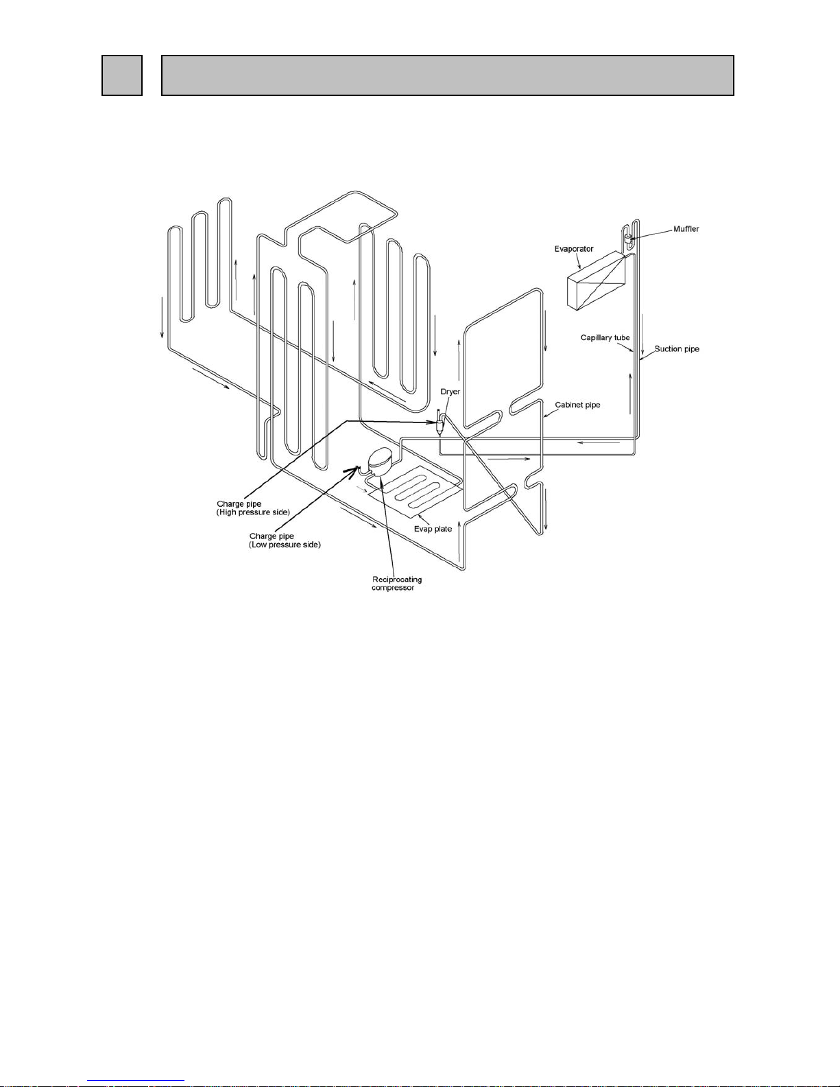
4 REFRIGERANT CIRCUIT
MR-CU375S/SL-A
MR-CU375S/SL-A(NZ)
- 7 -
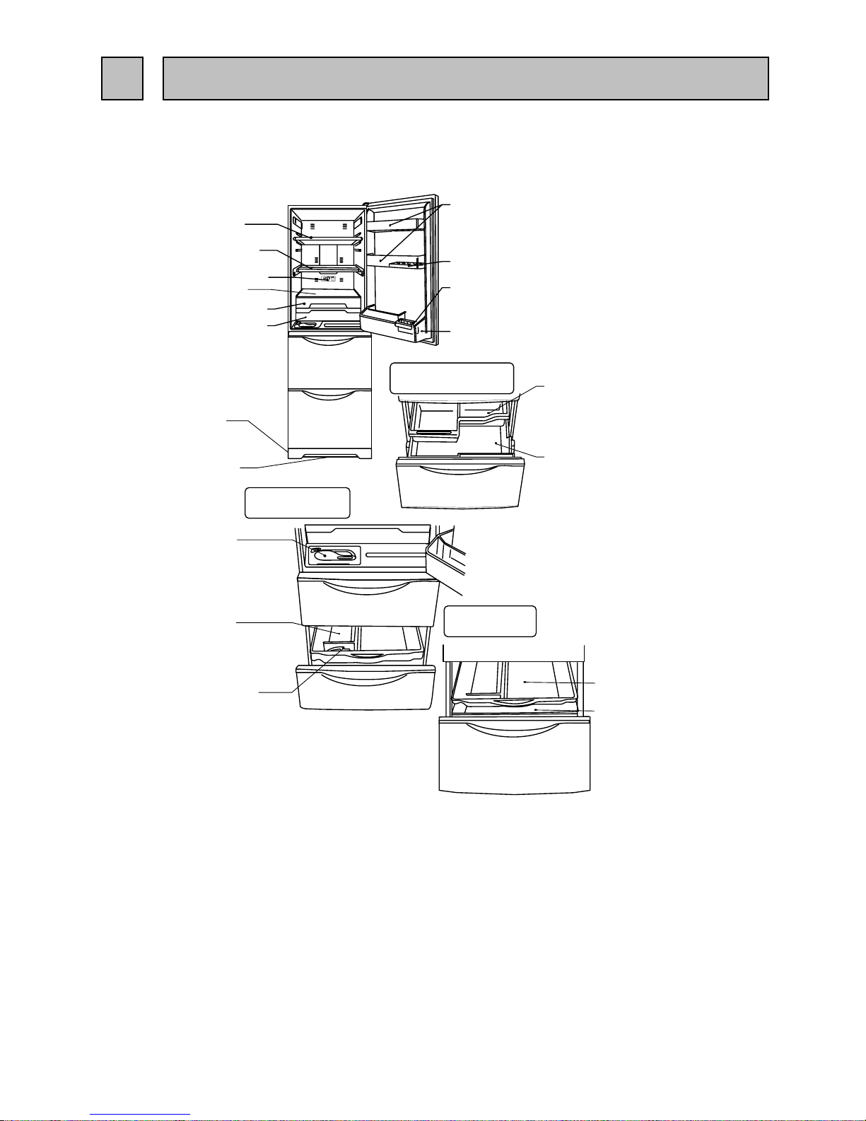
5 NAMES OF PARTS
Fruit case
Vegetable case
Water tank
Ice box sheet
Ice spoon
Freezing case (UP)
Freezing case (LOW)
Vegetable case room
Auto ice making
Freezer room
Free pocket (M)
Egg case
Tube stand
Bottle pocket
Crystal shelf (R)
Slide shelf
Thermo dial (R)
Slide Chilled case (UP)
Slide chilled case (LOW)
Top plate
Kick plate
Drain pan
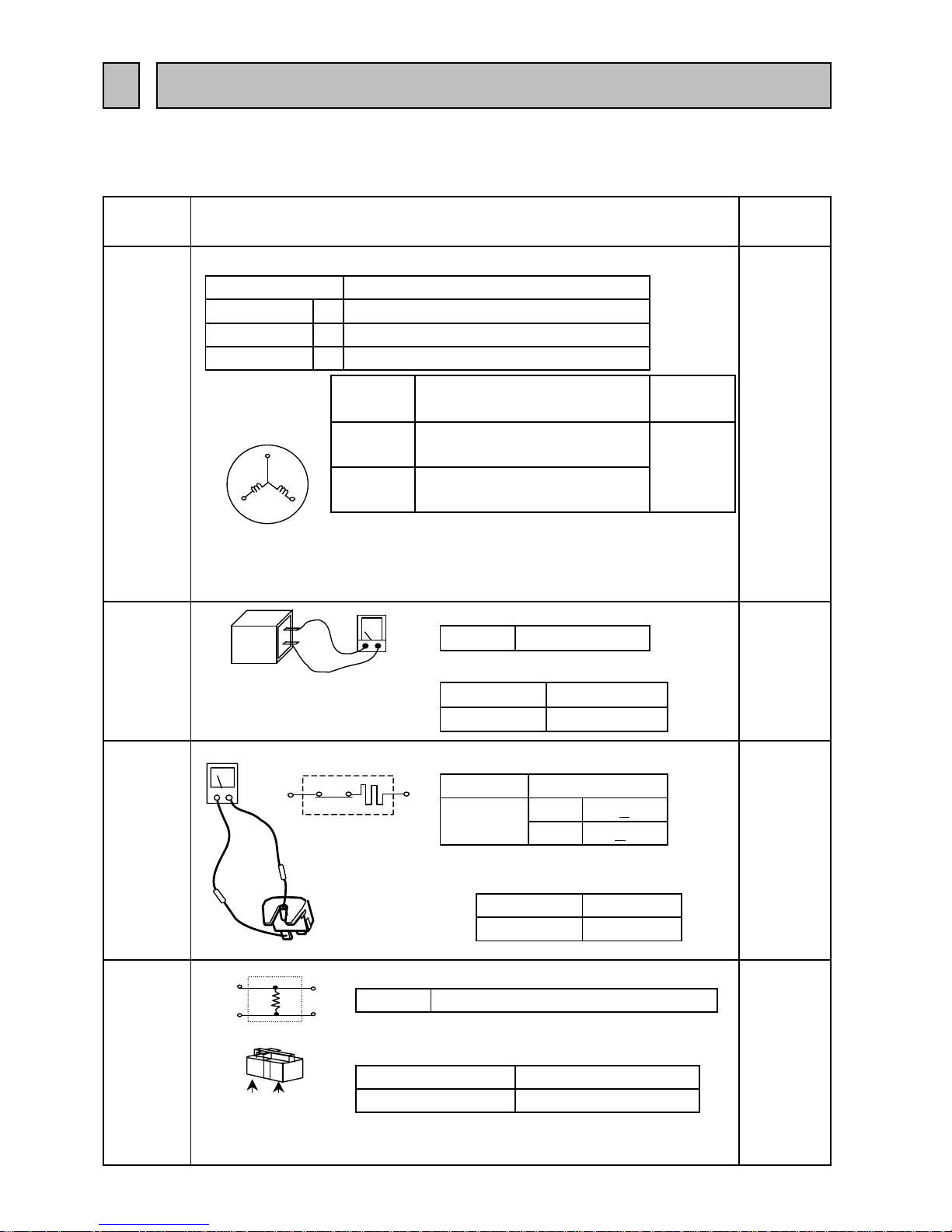
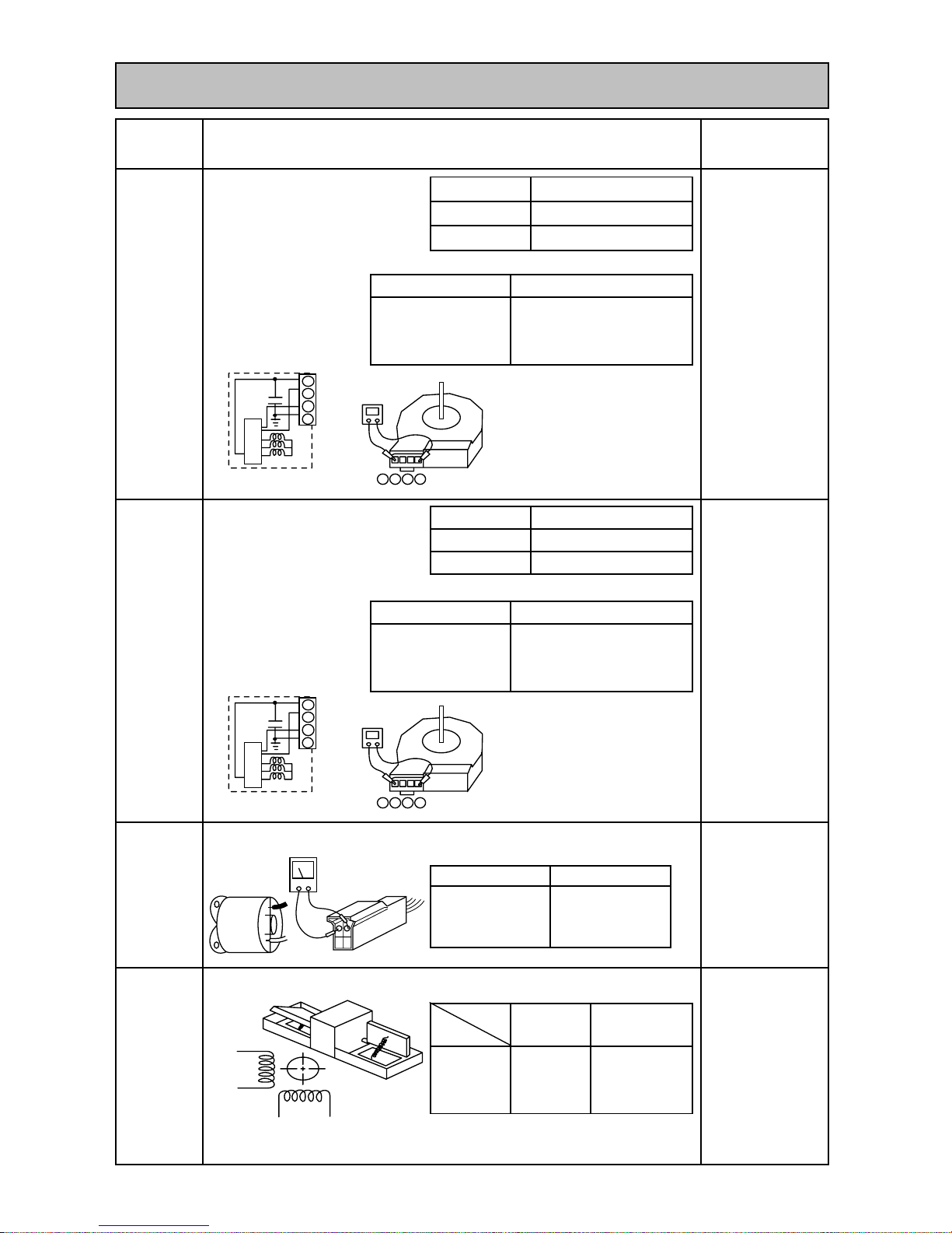
6.1 TROUBLE CRITERION OF MAIN PARTS
MR-CU375S/SL-A
MR-CU375S/SL-A(NZ)
Compressor
Measure the resistance with a tester.
(Ambient temperature:Room temperature 15
o
C ~ 25oC)
Measure the resistance with a teste
r
Open
Close
Opened (∞ Ω )
PTC Relay
PTH7M330MD2
Measure the resistance with a tester.
(Ambient temperature:Room temperature 15
o
C ~ 25oC)
Normal
As PTC Relay has been heated while refrigerator is running be sure
to measure the resistance after the thermistor has got cool enough.
33 Ω (Approx.)
Abnormal(faulty)
Opened (∞ Ω ) or Short (0Ω)
Rated input W 116/118 (220/240V 50Hz)
Short (0Ω )
15.1 Ω (Approx.)
Normal
Main wiring
A
Starting current
chamber at the
rear side of
0.57/0.55 (220/240V 50Hz)
A 8.49/9.31 (220/240V 50Hz)
Running current
Measure the resistance with a tester.(Ambient
temperature:Room temperature 15
o
C ~ 25oC)
69 + 9o C
Abnormal
(faulty)
5TM222NHBYY-53
Opened
(∞ Ω )
or
Short (0Ω)
120 +
5o C
Connected
Point
Normal
17.9 Ω (Approx.)
Auxilliary wiring
Run capacitor
4 µF
Rated input
Motor
protector
400VAC
Abnormal(faulty)
Model
the frame
the frame
In the control
panel of the
rear side at
compressor
room
Compressor in
the machine
chamber at the
rear side of
the frame
- 8 -
Model
Normal
Abnormal(faulty)
Less than 1Ω
rear side of
chamber at the
the machine
Compressor in
6
Components
/ Part Name
TROUBLE SHOOTING
Model
Parts
Mounted
Position
Check Method and Criterion
ESS60C11RAW (220-240V 50Hz)
Compressor in
the machine
Auxilialy
wiring
Main
wiring
5
6
3
2
5
6
2
3
1
3
Therminal check point
Measure the resistance with a tester.(Ambient temperature: Room temperature 15oC ~ 25oC)
Measure the resistance with a tester.(Ambient temperature: Room temperature 15
o
C ~ 25oC)
Measure the resistance with a tester.(Ambient temperature: Room temperature 15
o
C ~ 25oC)
Normal
Abnormal (faulty)
Measure the resistance with a tester.(Ambient temperature: Room temperature 15oC ~ 25oC)
Number of pole
DC brushless
Diameter
∅ 140 (Diagonal fan)
In the machine
chanber at the rear
side of the frame.
UDQM004B3
Model
Number of pole
DC brushless
Diameter
∅ 140 (Diagonal fan)
Open (∞Ω) or
short circuit (0Ω)
Motor
damper for
refrigerator
compartment
slide
compartment
In the fan grille of
the refrigerator
compartment.
Normal
415 Ω
(Approx.)
Model
Normal
Between 1 - 4 (GND
and IC Power ) :
About 12k Ω
- 9 -
Under the water
tank holder in
refrigerator
compartment.
Open (∞ Ω )
or short
circuit (0Ω)
Abnormal
(faulty)
Winding
(Blue-White,
Red-Yellow)
Water
pump motor
(DC 5V)
16 Ω (Approx.)
In the fan grille of
the refrigerator
compartment.
Refrigerator
fan motor
UDQM002B3
Machine
chamber
fan motor
Normal
Abnormal (faulty)
B
etween 1 - 4
(GND and IC
Power ) : About
9
k Ω
Between 1-4 : open( ∞
Ω ) or
between 3-4 : short ( 0 Ω)
Abnormal (faulty)
Between 1-4 : open( ∞
Ω ) or
between 3-4 : short ( 0 Ω)
Check Method and Criterion
Parts Mounted Position
Components/
Part Name
IC power
Power
GND
FG
IC
Pin no.
1
2
3
4
123
4
IC power
Power
GND
FG
IC
Pin no.
1
2
3
4
123
4
Yellow
Red
Blue Brown

Measure the resistance with a tester.(Ambient temperature:Room temperature 15oC ~ 25oC)
Measure the resistance with a tester.
(Ambient temperature:Room temperature 15oC ~ 25oC)
Measure the resistance with a tester according to t he f ollowing graph.
(Thermistor resistance values against temperature)
Resistance measured under the ambient temperature from - 50
o
C to +50 oC
1. 200 Ω to 500kΩ ............normal
2. Out of the above range ............abnormal
(kΩ)
Thermistor Check Procedure
Thermistor resistance will vary
with the change of temperature.
Take the temperature ar ound t he
thermistor, and then m easur e
thermistor resistance using a
tester.
The relation between resistance
and temperature is as shown on
the left side.
Trouble shooting with self-check
(1) If the self - check indicates the abnormality of thermistor right after the power is
turned on, measure the resistance of the thermistor.
If the circuit of thermistor is short , check the element of the thermistor and the
contact of the connector.
(2) When the self - check indicates the abnormality of thermistor a few seconds
after the power is turned on , check the contact of the connector.
Check Method and Criterion
Parts Mounted
Position
Components/
Part Name
384Ω (Approx.)
- 10 -
Rated input 150 W
operation method
Power ON after defrosting
(14 + 1.5oC or more)
Thermistor
Opened ( ∞ Ω )
Defrost
Heater
(Out air thermistor)
In the buzzer board
(check board)
(Defrost
thermistor) To the
cooler at the back of
vegetable
compartment
(Freezer
compartment
thermistor and Ice
making tray
thermistor) In Ice
maker of freezer
compartment
Abnormal (faulty)
(Refrigerator
compartment
thermistor) In the
control panel of
refrigerator
compartment
Water pipe
heater
Normal
Abnormal (faulty)
1.3 kΩ (Approx.) Open (∞ Ω )
Normal
At the left
bottom of
vegetable
compartment
The heater is turned on when th e temperature of tray
for automatic ice mak i ng tray is about 10
o
C or less
Operation method
In the drip tray
under the
evaporator of the
freezer
compartment
-20
20 30
-10
0
10
30
20
15
10
5
0
25
35
Thermistor resistance valves against
temperature
Temperature
Black
Black
Outside air thermistor
Refrigerator
compartment,
Freezer
compartment,
Defrosting,
Ice making
Inner
thermistor

13,14
11

6.3 FLOW CHART OF SELF-CHECK
(1) Trouble shooting with self-check
This refrigerator has self-check feature to clarify and indicate where & what the trouble is. It can be checked that
there is something wrong with electronic circuit and electric parts.
Remark
(2) Timing of self-check
Defrost heater and related parts :
Self-check is conducted after defrosting.(Make sure to confirm the display before unplugging
because it is automatically reset once the power cord is pulled out.)
Ice maker and related parts :
To check the ice- making and then, check the blink amount of LED see the reference as (3)
Fan motor and related parts :
To check the blink amount of LED see the reference as (3)
Thermistor and related parts :
Self-check is continuously working.
Caution: The self-check will automat ic start to begin power supply. But in the portion of the abnormality show the detail as (3) .
And the caution checking couldn't be summar ized, please use self- c heck means by using operation panel.
- 12 -
Self-check
Press Ice making stop button
Was trouble
displayed?
Locate the trouble according to
LED indication.(See page13,14)
Disconnect power plug
Repair/replace defective part(s)
according to LED indication
Connect power plug ∗
Press Ice making stop button
Self-check ,Ice making stop
LED blink during the operational
test of automatic ice maker.
Check the parts whose
Abnormalities cannot be
detected by self-check.
(Remark.1)
Is error no
longer
displayed?
Self-check is finished.
Slide room
Refrigerator room
Ice making
stop LED
Refrigerato
r
Freeze
r
Ice maker of
f
No
No
Yes
Yes
∗
Wait 10 minutes
before inserting the cord
once it's unplugged.(If
the cord is plugged in
within 10
minutes,trouble may be
display.)
During the ice making test
mode,watch the operation of ice
maker gear box and water pump
in refrigerator.
Is trouble no
longer displayed?
No
1.) Self-check cannot detect abnormalities of the
following parts. See page 10~12 for trouble
criterion of main parts.
- Freezer & refrigerator door sw NG
- Thermo heater NG ( Water pipe / Vegetable
case heater etc.)
- Motor damper NG (See page 12.)
- Water pump motor NG (See page 12.)
2.) If the abnormality is found when power is
turned on, compressor and fan motor will be
suspended for 20 minutes.

(3) LED trouble display and the check point
(3.1) LED trouble display : follow the procedure of "self check method
and its operation" at page 11. Trouble is indicated by the blinking number
of ice making stop LED.
∗ When several troubles occur
,
smaller blinking number of LEDs has to be indicated first.
(3.2) Check point and treatment
Normal
1. Normally display and the Auto ice-maker
system display.
* If non-power supply, it'll show as same
the effect.
Auto ice maker NG
1. The connector lead wire of Auto ice maker 1. Check all points of the Auto ice maker
is not orderly. connector lead wire. May be un-lock
and struck insert.
2. 2.
3.
3. PCB plate ( Ref Con assy) NG
Thermistor(I) NG
1.
The connector thermistor (I) lead wire 1.
Check all points of the thermistor (I)
isn't orderly.
connector lead wire, may be unloc
k
and struck insert.
2.
Thermistor (I) NG (break or short) 2.
If the resistance of thermistor (I) is NG,
should be changed the thermistor and
re-check the resistance.
3.
PCB plate (Ref Con assay) NG 3.
If the resistance is OK,should be changed
PCB plate (Ref Con assy and re-check
the resistance).
Thermistor (F) NG
1. The connector thermistor (F) lead wire 1.
Check all points of the thermistor (F)
isn't orderly.
connector lead wire, may be unloc
k
and struck insert.
2. Thermistor (F) NG (break or short) 2.
If the resistance of thermistor (F) is
NG,should be changed the thermistor and
re-check the resistance.
3. PCB plate (Ref Con assy) NG 3.
If the resistance is OK,should be changed
PCB plate (Ref Con assy and re-check
the resistance.
Thermistor (DEF) NG
1. The connector DEF. thermistor lead wire 1.
Check all points of the thermistor
isn't orderly.
(DEF) connector lead wires, may be
unlock and struck insert.
2. Thermistor (DEF) NG (break or short) 2.
If the resistance of thermistor (DEF) is
NG,should be changed the thermistor and
re-check the resistance.
3. PCB plate (Ref Con assy) NG 3.
If the resistance is OK,should be changed
PCB plate (Ref Con assy and re-check
the resistance.
Defrost heater NG
1. 1.
2. Defrost heater break or 2.
Thermal fuse break.
and thermal fuse.
3. PCB plate (Ref Con assy) break. 3.
If the resistance is OK,should be changed
PCB plate (Ref Con assy and re-check
the resistance.
-13 -
isn't orderly.
maker.
Replace and re-check the PCB plate
and non-display)
connector lead wire, may be un-lock
Blink
Blink
Light
Light
Light
1 Blink
No Light
Display function of LED
Off
NO
Function Explanation
Light
No Light
Detecting method and corrective NG points
2 Blinks
Check the resistance of the defrost heate
r
and struck insert.
3 Blinks
Light
No Light
No Light
No Light
0.1 second
0.3 seconds
No Light
Replace and re-check the Auto ice
( Ref Con assy)
A
uto ice maker (Motor's not rotate
The Defrost heater connector lead wire
Check all points of the defrost heater
Light
0.1 sec
5 sec
1
1
5 sec
1 2 1 2
5 sec
1 2 13
1 Cycle
0.1 sec
0.3 sec 0.3 sec
0.3 sec
1 Cycle
0.3 sec
1 Cycle
0.3 sec
Slide room
Refrigerator room
Ice making
stop LED
Refri
g
erato
r
Freeze
r
Ice maker off

Thermistor (R) NG
1. The Thermistor (R) connector lead wire
1. Check all points of Thermistor (R) connector
isn't orderly.
lead wire, may be unlock and struck insert.
2. Thermistor (R) NG (break or short)
2. If the resistance of Thermistor (R) is NG,
should be replaced the Thermistor (R) and
re-check the resistance.
3. PCB plate (Ref Con assy) NG
3. If the resistance is OK., should be replaced
PCB plate (Ref Con assy) and re-check the
resistance.
Thermistor (A.T.) NG
1. The Thermistor (A.T.) connector lead 1. Check all points of the thermistor (A.T.)
wire isn't orderly. connector lead wire, may be unlock and
struck insert.
2. Thermistor (A.T.) NG (break or short) 2. If the resistance of Thermistor (A.T) is NG,
3. PCB plate (Ref Con assy) NG should be replaced the Thermistor (R)
and re-check the resistance.
3. If the resistance is OK., should be replaced
PCB plate (Ref Con assy) and re-check the
resistance.
1. DC motor is orderly connected. 1. Check all points of DC motor connector
lead wire, may be unlock and struck insert.
2. DC motor NG (Motor un-rotate and 2.
non-display) re-check display.
3. PCB plate (Ref Con assy) NG 3. If the resistance is OK., should be replaced
PCB plate (Ref Con assy) and re-check the
resistance.
1. DC fan motor is orderly connected. 1. Check all points of DC Fan motor connector
lead wire, may be unlock and struck insert.
2. DC fan motor NG (Motor un-rotated, 2. Replace DC fan motor (Outer motor assy)
and non-display.) and check display.
3. PCB plate (Ref Con assy) NG 3. If the resistance is OK., should be replaced
PCB plate (Ref Con assy) and re-check the
resistance.
PCB plate (Ref Con assy) NG
1. PCB program (Ref Con assy) is NG 1. Replace a new PCB plate (Ref Con assy)
Refrigerant circuit is NG.
1. Pipe cracked (Welding joint) 1. Check and corrective to each problem.
2. Gas leak
3. Compressor NG
Remark :
1.) For the refrigerator is NG more than one case, will show as the first symptoms before, such as Thermistor (F) NG (1 blink in 0.3 seconds) and
Thermistor (R) NG (4 blinks in 0.3 seconds). LED will blink 1 blink in 0.3 seconds until Thermistor (F) was corrected. Then change to 4 blinks in 0.3 seconds
and LED won't blink when Thermistor (R) was corrected.
2.) Ice making stop LED blink during the operational test for ice maker.
3.) Compressor won't work if the fridge have problem and LED blink.
4.) Characteristic value may be changed due to the product improvement.
-14 -
6 Blinks
Display function of LED
Light
No Light
Light
Function Explanation Detecting method and corrective NG points
4 Blinks
Replace DC motor (Fan grille assy) and
Fan motor (Fan grille assy) NG
11 Blinks
Fan motor (Outer motor assy) NG
Light
Light
No Light
No Light
Light
No Light
10 Blinks
No Light
Light
16 Blinks
No Light
19 Blinks
5 sec
1 2 3
1 Cycle
4
1 2 6
1 Cycle
1 2
1 2 10
1 Cycle
1 2
1 2 11
1 Cycle
1 2
1 2 16
1 Cycle
1 2
1 2 19
1 Cycle
1 2
0.3 sec
0.3 sec
0.3 sec
0.3 sec
0.3 sec
0.3 sec

6.4 TEST POINT DIAGRAM OF MAIN CONTROL BOARD
MR-CU375S/SL-A
MR-CU375S/SL-A(NZ)
-15 -
1 = INNER FAN MOTOR VCC
2 = GND
3 = ICE MAKER POSITION SW
4 = DAMPER
5 = INNER FAN MOTOR FG
6 = DAMPER
7 = INNER FAN MOTOR DC+
8 = DAMPER
9 = ICE MAKER AND WATER PUMP FORWARD
10= DAMPER
11= ICE MAKER REVERSE
12 = WATER PUMP DC-
1 = OUTER FAN MOTOR VCC
2 = GND
3 = OUTER FAN MOTOR FG
4 = OUTER FAN MOTOR DC+
1 = 5 V COMMON
2 = DOOR SW
6 = DEF THERMISTOR
7 = ICE TRAY THERMISTOR
8 = R THERMISTOR
9 = F THERMISTOR
11 = ICE MAKER STOP SW
12
14 = ICE MAKER STOP LED
16 = DIAL R
17 = DIAL F
18 = GND
1 = 5 V COMMON
2 = OUTER THERMISTOR
3 =COMPULSION DEF
4 = BUZZER
1 =
3 = 230V AC COMMON 3 = V HEATER 5 = 12V
230 VAC
5 = COMPRESSOR 5 = PIPE HEATER
3 =
7 = DEFROST HEATER 11= LAMP
CN4CN10CN7CN9
CN1 CN2 CN3
+
-
325V DC12V DC
+
-
+
-
5V DC

DISASSEMBLY INSTRUCTIONS
MR-CU375S/SL-A
MR-CU375S/SL-A(NZ)
Plug out before work.
Check the automatic i ce-maker by pressing ice making stop switch.
In assembling & disassembling parts us e several kind of Screw and Rivet. Do not mistake to use them .
1. Detachment Control PCB parts Photo 1
Compressor cover
(1) Detach 7 pcs. of compressor cover sc rews behind the
refrigerator. (Photo 1)
Elect cover
(2) Detach 7 pcs. of Elect cover screws. (Photo 2)
Elect attach Photo 2
(3) Disconnect the connector and remove Elect attach. (Photo 3)
PCB(Ref Con assy)
(4) Remove the catch of elect attach to releas e the PCB plate.
(Photo 3)
Caution on assembly Photo 3
(1) Firmly connect the lead wire and the connector. Ensure the
wire are not pinched.
(2) Please use the new material of sealing insulation when
re-attach.
2. Detachment Lamp cover parts Photo 4
(1) Remove parts inside the refrigerator Shelf 1,2,3 s hel f
Lamp cover inside the refrigerator
(1) Push up the lower catch, and pull the room light cover toward you.
(2) Detach two upper catches to take out the cover (Photo 4)
OPERATING PROCEDURE PHOTOS
7
-16 -
7 fixing screws
Comp cover
Elect
PCB
Catch
Catch
Catch
4 x12
4 x12 (Black) With metal washer
Rivet
A
B
D
C
Rivet
7 fixing screws
Elect cover
Lamp cover

3. Detachment the Vegetable case parts Photo 5
(1) Detach parts inside vegetable compartment (Vegetable case, Fruit case).
(2) Detach the door of vegetable compartment.
(3) Detach rivet (F ) at the right and unhooking 2 catch at front,
(center and left). (Photo 5)
Caution on assembly
Be sure to put vegetable case cover on the catches at the rear of
vegetable compartment.
Water pump motor
(4) Remove two screws and cut the lead wire of water-pump motor to
detach it.
4. Detach the refrigerator room parts Photo 6
(1) Detach parts inside the refrigerator compartment.
(See procedure (2))
(2) Detach parts inside the vegetable compartment.
(See procedure (3))
(3) Detach a left screw of mirror hinge and pull out the lead wire.
(Photo 7)
(4) Detach the connect or.
Control panel ,Duct R, Temperature control panel Photo 7
(5) Remove the upper and lower rivets (F) of right side and unhook 6 catches.
* Remove the right catch before push the control panel to the right
and detach it. (Photo 7)
Fan grille
(6) Remove the following; Screw (A) at the upper and right center,
2 screws (B) at the left and 2 screws (B) at the right.
* Motor damper and thermal fuse are combined with fan grille.
* Fan and fan motor are combined with fan grille.
Caution on assembly
(1) Use new tapes and sealing materials for assembly.
(2) Putting some tape across joints, tape them securely so that they will
not leak the cool air.
(3) Attach a connect or securely in order to prevent contact failure.
OPERATING PROCEDURE PHOTOS
- 17 -
Rivet
Catches
Catch
Catch
Vegetable cave
cover
Vegetable cave
ScrewScrew
Fan grille
F-room
Catch
CatchCatch
Catch
Catch
Catch
Screw
Screw
Screw
Lamp
Rivet
Mirror hinge
Fan grille
Control panel

OPERATING PROCEDURE PHOTOS
r
Defrost heater Drip tray Photo 8
(7) Peel off the tape that f i xes lead wires on t he side wall
of the vegetable compartment. Then take out defrost heater
together with heater roof.
Detach heater roof and Heater cover from Defrost heater.
Detach the drip tray after removing the defrost heater.
Defrost thermistor
(8) Cut the binder and disconnect t he connector. (Photo 9)
Caution on assembly
1) Loosen the lead wire at the defrost heather to prevent
water from entering the glass t ube and careful the
direction for the correct assembly.
2) Attach the drip t ray securely to the lower parts.
3) Attach the defrost thermistor in t he correct place. (If
they're attached out of plac e, thermal characteris tics
will go wrong).
Photo 9
Tape
Defrost
Aluminium tape
Heater roof
Defrost
Evaporato
Drip tray
Heater cover
DEF thermistor
Tape
DEF
4) Attach the lead wires to t he fixture.
5 Detachment the parts in Freezer compartment
(1) Detach the parts inside t he Freezer room (Ice spoon,
Freezing case [upper] and Freezing case [ l ower] ).
(2) Pull the door of Freezer compartm ent by pulling t oward you.
Cover (upper)
(3) Detach 3 catches and remove it.
(4) Disconnect the connec t or.
Automatic ice-maker
(5) push a catch to upper and pull the part to the right
and detach it. (Photo 10)
Photo 10
Cover
Ice corner
Rivet
Catch
Rivet
Catch
F- room
-18 -

OPERATING PROCEDURE PHOTOS
6 Detachment the vegetable compartment parts Photo 11
(1) Detach the door of the vegetable compartment.
Water pipe (lower)
(2) Detach a rivet (E), pipe cover and c onnector. Then
remove the water pipe lower.
Water tank tray
(3) Pull Tank tray to R-room upper and t ake it out together Photo 12
with the water pipe.
Caution on assembly
(1) Fit the water tank tray properly in order to prevent a
water leak.
DOOR SW.
(4) Insert a minus s crewdriver between switch and body
to remove the door switch.
Pipe cover
Vegetable case room
R-room
Water
Tank tray
-19 -

Compressor cover
(1) Remove 7 screws for compressor cover at the back of the refrigerator.
Fan motor of compressor compartment
(2) Detach the Elect cover
(3) Detach the Connector.
(4) Remove a screw that fixed bellmouth. Pull out the whole fan motor and disconnect the terminals.
(5) Pull out the fan from the fan motor.
(6) Detach the lid-fixing screw to take out the fan motor.
7 Detachment compressor.
(1) Collect gas from the charge pipe on the high pressure side.
(2) After collecting gas, cut the charge pipe on the low pressure side.
(3) Detach the welded section of the discharge pipe and suction pipe.
(4) Replace the compressor and the dryer at a time.
Caution on assembly
(1) After attaching the compressor, must to Vacuum and charge gas from charge pipe.
(2) Arrage the piping so that the pipe will not hit each other and compressor cover, (which causes loud noise). Then
attach the compressor cover.
(3) After all the work is complete, be sure to check the cooling preformance and the gas leak from the welded points.
- 20 -
OPERATING PROCEDURE
Keep the clearance between each parts about the big
of fiinger (for 10 -15 mm.)
Attach U washer as the figure shown below
This mark shows welded point.
Heat radiation pipe at the left.
Machine chamber
fan motor
Charge pipe(Low pressure side)
Dryer
W
W
W
W
W
W
W
W
W
W
W
W
Heat radition pipe at the right.
Heat rediation pipe of
flat face flange
Heat radiation pipe at back
Heat radiation pipe at back side

DOOR PARTS
MR-CU375S/SL-A
MR-CU375S/SL-A(NZ)
- 21 -
8 PARTS LIST
1
2
3
4
5
6
13
12
11
10
9
8
7

WSTWSTWSTWST
KIEK96000
<G>
11
KIEK97000
<G>
11
KIEK98000
<G>
11
KIEK99000
<G>
11
KIEK96002
<G>
1111
KIEHB1002
<G>
1111
KIEK96001
<G>
1111
KIEHB1001
<G>
1111
KIEB66746
<G>
1111
KIEEA3746
<G>
1111
5
KIEHJ3151
<G>
FRAME (V)
11111111
6
KIEHJ3157
<G>
FRAME (F)
11111111
7
KIEHJ3118
<G>
FREE POCKET (M)
22222222
8
KIEHJ3115
<G>
EGG CASE
11111111
9
KIEHJ3139
<G>
TUBE STAND
11111111
10
KIEHN8110
<G>
MAGNET GASKET ASSY ( R )
11111111
11
KIEHJ3124
<G>
BOTTLE POCKET
11111111
12
KIEHJ3112
<G>
MAGNET GASKET ASSY ( V )
11111111
13
KIEHJ3111
<G>
MAGNET GASKET ASSY ( F )
11111111
RECOMMEND PART NO. 1,2,3,10,12,13
ABBREVIATION
- 22 -
PRICESPEC
CU375S
A
A
(NZ)
A
Q'TY/UNIT
CU375SL
DOOR V
DOOR F3
A(NZ)
DOOR STOPPER (R)4
RoHS
PART NO. PART NAMENO.
1 DOOR R
2
FRFREEZER ROOM
REFRIGERATOR ROOM
V VEGETABLE ROOM

BODY PARTS
MR-CU375S/SL-A
M
R
MR-CU375P/PL-A(NZ)
- 23 -
1
2
3
4
5
6
7
8
9
10
11
26
25
24
23
22
21
20
19
18
17
16
15
14
12
13
11

WSTWSTWSTWST
1 KIEHN8858
<G>
CONTROL PANEL 11111111
2 KIEHJ3305
<G>
THERMO DIAL (R) 22222222
3 KIEHJ3503
<G>
WATER TRAY ASSY 11111111
4 KIEK96663
<G>
FAN GRILLE ASSY 11111111
KIEHJ3708
<G>
1111
KIEHH5708
<G>
1111
6 KIEHJ3442
<G>
PIPE COVER 11111111
7 KIEHJ3350
<G>
A
UTO ICE MAKER 11111111
8 KIEHJ3652
<G>
COMP COVER ASSY 11111111
9 KIEHJ3328
<G>
ELECT COVER 11111111
10 KIE805794
<G>
CASTER SET 22222222
11 KIEHJ3709
<G>
SCREW LABEL (F) 22222222
12 KIE805795
<G>
CASTER ASSY 22222222
13 KIEC02460
<G>
A
DJUST BOLT 22222222
KIEHJ3705
<G>
11
KIEHH5705
<G>
11
KIEHJ2705
<G>
11
KIEJM7705
<G>
11
KIEHJ3701
<G>
1111
KIEHJ2701
<G>
1111
16 KIEHJ3470
<G>
LAMP COVER 11111111
17 KIEHJ4503
<G>
JOINT PIPE (TANK) 11111111
18 KIEHJ3531
<G>
WATER TANK CAP 11111111
19 KIEHJ3519
<G>
WATER PUMP 11111111
20 KIEK96527
<G>
WATER TANK COVER ASSY
11111111
KIEHJ3702
<G>
1111
KIEHJ2702
<G>
1111
22 KIEHJ3798
<G>
ROLLER 44444444
23 KIEHJ3520
<G>
WATER TANK 11111111
24 KIEHJ3526
<G>
FILTER (TANK) 11111111
25 KIEHJ3442
<G>
COVER (IM) 11111111
KIEKA0730
<G>
1111
KIEKA1730
<G>
1111
27
KIEK96663
<G>
FAN GRILLE 11111111
28
KIEHJ4662
<G>
BELL MOUTH 11111111
29
KIEHJ3320
<G>
FAN MOTOR
UDQM002B3
11111111
30
KIEHJ4321
<G>
FAN (IN) 11111111
31
KIEHJ4682
<G>
DUCT DAMPER 11111111
32
KIEHJ4336
<G>
THERMAL FUSE ASSY 11111111
RECOMMEND PART NO. 4,18, 20,32
ABBREVIATION
ENCIRCLED PART NUMBER ARE NOT SHOWN IN THE FIGURES.
CU375S
A
A
(NZ)
A
Q'TY/UNIT
CU375SL
A(NZ)
- 24 -
NO. PART NAMEPART NO. PRICESPEC
26
RoHS
KICK PLATE
5 LABEL FC
14
HINGE ASSY (UP)15
HINGE ASSY (LOW)21
HINGE COVER
FRFREEZER ROOM
REFRIGERATOR ROOM
IMVICE MAKER
VEGETABLE ROOM

ELECTRICIAL PARTS
MR-CU375S/SL-A
MR-CU375S/SL-A(NZ)
- 25 -
1
2
3
4
5
6
9
10
11
12
13
14
25
26
25
24
23
22
21
20
19
18
17
10
16
15
8
7

WSTWSTWSTWST
1 KIEHJ3313
<G>
THERMISTOR (R) 11111111
2 KIEHD6386
<G>
LAMP SOCKET 11111111
3 KIE402360
<G>
LAMP
E12 240V 15W
11111111
4 KIEHJ3312
<G>
THERMISTOR (DEF) 11111111
5 KIEHJ3378
<G>
THERMISTOR (F) 11111111
6 KIEHJ3365
<G>
WATER PUMP 11111111
7 KIEHJ3469
<G>
GEAR BOX (IM) 11111111
8 KIEHJ3316
<G>
THERMISTOR (I) 11111111
9 KIEHB2354
<G>
PLUG CORD ASSY 11111111
10 KIEHJ3362
<G>
LAMP SWITCH 22222222
11 KIEHJ3364
<G>
WATER PIPE ASSY 11111111
12 KIEK96339
<G>
REFCON ASSY 11111111
13 KIECC9346
<G>
RUNNING CAPACITOR 4µF 400VAC 11111111
14 KIEHJ3662
<G>
BELL MOUTH M 11111111
15 KIEKA0374
<G>
BUZZER BOARD &
THERMISTOR (A.T.)
11111111
16 KIEKA0382
<G>
TEMP CONTROL PANEL
11111111
17 KIEHJ3537
<G>
HEATER ROOF 11111111
18 KIEHP1392
<G>
DEFROST HEATER
240V, 150W NOT
DEODORIZER
11111111
19 KIEHJ3397
<G>
HEATER COVER 11111111
20 KIEHJ3538
<G>
DRIP TRAY 11111111
21 KIEG01340
<G>
MOTOR PROTECTOR
5TM222NHBYY-53
11111111
22 KIEE76330
<G>
PTC RELAY
PTH7M330MD2
11111111
23 KIEHJ3341
<G>
THERMINAL COVER 11111111
24 KIEHJ3321
<G>
FAN (OUT) 11111111
25 KIEHJ3329
<G>
FAN MOTOR BUSH 22222222
26 KIEHJ3325
<G>
OUT FAN MOTOR
UDQM004B3
11111111
RECOMMEND PART NO. 1 , 3, 4, 5, 8, 12, 15, 16, 18, 21, 22
Q'TY/UNIT
CU375SL
A(NZ)
CU375S
- 26 -
NO. PART NAMEPART NO. PRICESPEC
A
A
(NZ)
RoHS
A

ACCESSORY AND UNIT PARTS
MR-CU375S/SL-A
MR-CU375S/SL-A(NZ)
- 27 -
1
5
14
16
20
21
18
17
15
13
19
2
3
4
5
8
10
11
12
9
7
6

WSTWSTWSTWST
1 KIEHJ3420
<G>
CRYSTAL SHELF (R) 11111111
2 KIEHJ3427
<G>
SLIDE SHELF (REAR) 11111111
3 KIEHJ3428
<G>
SLIDE SHELF (FRONT) 11111111
4 KIEHJ3411
<G>
SLIDE CHILLED CASE (UP) 11111111
5 KIEG59471
<G>
STOPPER 22222222
6 KIEHJ3413
<G>
SLIDE CHILLED CASE (LR) 11111111
7 KIEHJ3409
<G>
VEGEATABLE CASE COVER 11111111
8 KIEHJ3406
<G>
FRUIT CASE 11111111
9 KIEHJ3468
<G>
ICE BOX SHEET 11111111
10 KIEJ77474
<G>
FREEZING CASE (UP) 11111111
11 KIEHJ3477
<G>
ICE SPOON 11111111
12 KIEHJ3475
<G>
FREEZING CASE (LOW) 11111111
13 KIEKA0479
<G>
TOP PLATE 11111111
14 KIEHJ3405
<G>
VEGEATABLE CASE 11111111
15 KIEE76435
<G>
DRAIN PAN 11111111
16 KIEHJ3995
<G>
EVAPORATOR 11111111
17 KIEHJ3735
<G>
U WASHER 44444444
18 KIEHJ3797
<G>
RUBBER MOUTH 44444444
19 KIEAA1980
<G>
DRYER 11111111
20 KIEHD6277
<G>
COMPRESSOR
ESS60C11RAW
11111111
21 KIEHJ3940
<G>
E PLATE FINAL ASSY 11111111
RECOMMEND PART NO. 1, 2, 3, 4, 6, 16, 19, 20
CU375SL
A(NZ)
A
(NZ)
A
- 28 -
NO. PART NAMEPART NO. PRICESPEC
CU375S
RoHS
A
Q'TY/UNIT

PACKING PARTS
MR-CU375S/SL-A
MR-CU375S/SL-A(NZ)
- 29 -
NO STEP ON
1
C.F.B BOX ASSY
7
C.F.B TOP COVER
4
SIDE CUSHION ASSY
3
PACKING COVER
6
C.F.B PALLET
5
BOTTOM CUSHION
L
R
2
TOP CUSHION

WSTWSTWSTWST
KIEK96970 <G> 1 1
KIEK97970 <G> 1 1
KIEK98970 <G> 1 1
KIEK99970 <G> 1 1
2 KIEHJ3979 <G> TOP CUSHION 11111111
3 KIEHN8973 <G> PACKING COVER 11111111
4 KIEHB2971 <G> SIDE CUSHION ASSY 11111111
5 KIEHJ3978 <G> BOTTOM CUSHION 11111111
6 KIEHJ3974 <G> C.F.B PALLET 11111111
7 KIEHJ3975 <G> C.F.B TOP COVER 11111111
CU375SL
A(NZ)
CU375S
A
A
(NZ)
A
1 C.F.B BOX ASSY
- 30 -
NO. PART NAMEPART NO. PRICESPEC
RoHS
Q'TY/UNIT

MITSUBISHI ELECTRIC CORPORATATION
HEAD OFFICE : MITSUBISHI DENKI BLDG., MARUNOUCHI,TOKYO 100. TELEX : J24532 CABLE MELCO TOKYO
Distributed by Mitsubishi Electric Australia
MITSUBISHI ELECTRIC AUSTRALIA PTY LTD.
(Incorporated in New South Wales) ABN 58 001 215 792
New South Walse : Queensland: South Australia /
348 Victoria Road, Unit 12, 469 Northern territory :
Rydalmere NSW 2116 Nudgee Road, 77 Port Road
Ph : (02) 9684 7777 Hendra, 4011 Hindmarsh SA 5007
Fax : (02) 9898 1043 Ph : (07) 3263 2000 Ph: (08) 8340 2000
Fax : (07) 3630 1888 Fax : (08) 8340 0555
Western Australia : Victoria / Tasmania : Far North
329 collier Road, Unit 4, 303 Burwood Queensland:
Bassendean WA 6054 Hightway, Capricorn Air,
Ph : (08) 9377 3400 East Burwood 3151 13 Mackley St,
Fax : (08) 9377 3499 Ph : (03) 9262 9855 Garbutt 4814
Fax : (03) 9262 9844 Ph: (07) 4775 5222
Fax : (07) 4775 5303
Distributed by
BLACK DIAMOIND TECHNOLOGIES LIMITED (BDT)
Wellington Office (Head Office)Auckland Office Christchurch Office
1 Parliament Street Unit1, 4 Walls Road Suite 2, Level 1
PO Box 30-772 Penrose 37 Manderville Street
Lower Hutt
A
uckland PO Box 12-726 Chischurch PO Box 1604
Ph : (04) 560 9100 Ph: (09) 526 9340 Ph : (03) 341 7052
Fax : (04) 560 9133 Fax : (09) 526 9369 Fax : (03) 341 7054
 Loading...