

Mitsubishi Electric MR-CU375S-W-A, MR-CU375S-W-ANZ, MR-CU375S-ST-ANZ, MR-CU375S-ST-A, MR-CU375SL-W-A Service Manual
...
Changes for the Better
Models
CONTENTS
A………….......Australia
A(NZ)...............New Zealand
1. SPECIFICATIONS....................................................
2. OUTLINES AND DIMENSIONS..................................
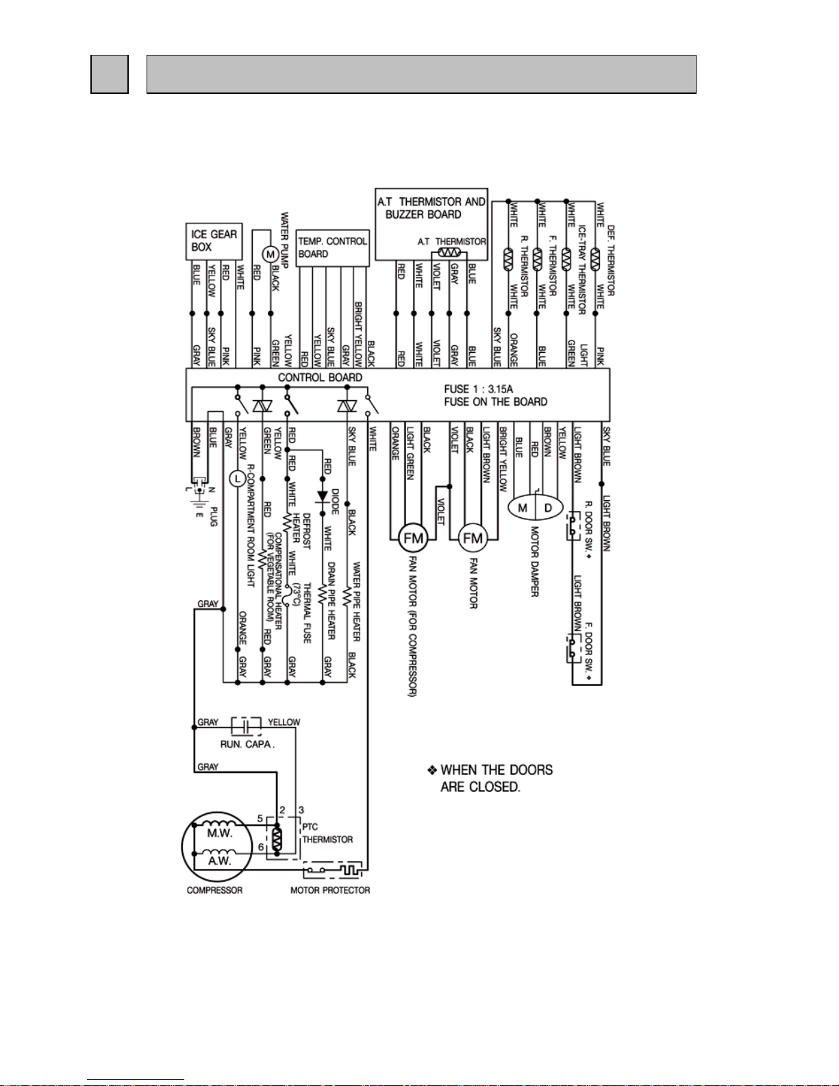
3. WIRING DIAGRAM....................................................
4. REFRIGERANT CIRCUIT...........................................
5. NAMES OF THE PARTS...........................................
6. TROUBLE SHOOTING..............................................
6.1 TROUBLE CRITERION OF MAIN PARTS.......
6.2 FUNCTION OF OPERATION PANEL..............
6.3 FLOW CHART OF SELF-CHECK....................
6.4 TEST POINT DIAGRAM OF MAIN CONTROL
BOARD........................................................
7. DISASSEMBLY INSTRUCTIONS...............................
8. PARTS LIST............................................................
1
3
4
6
7
8
8
11
12
15
16
21
MR-CU375S-W-A
MR-CU375S-ST-A
MR-CU375S-W-A(NZ)
MR-CU375S-ST-A(NZ)
MR-CU375SL-W-A
MR-CU375SL-ST-A
MR-CU375SL-W-A(NZ)
MR-CU375SL-ST-A(NZ)
2006
SERVICE MANUAL
NO.SM-RE-0605
MITSUBISHI
ELECTRIC
HOME REFRIGERATORS
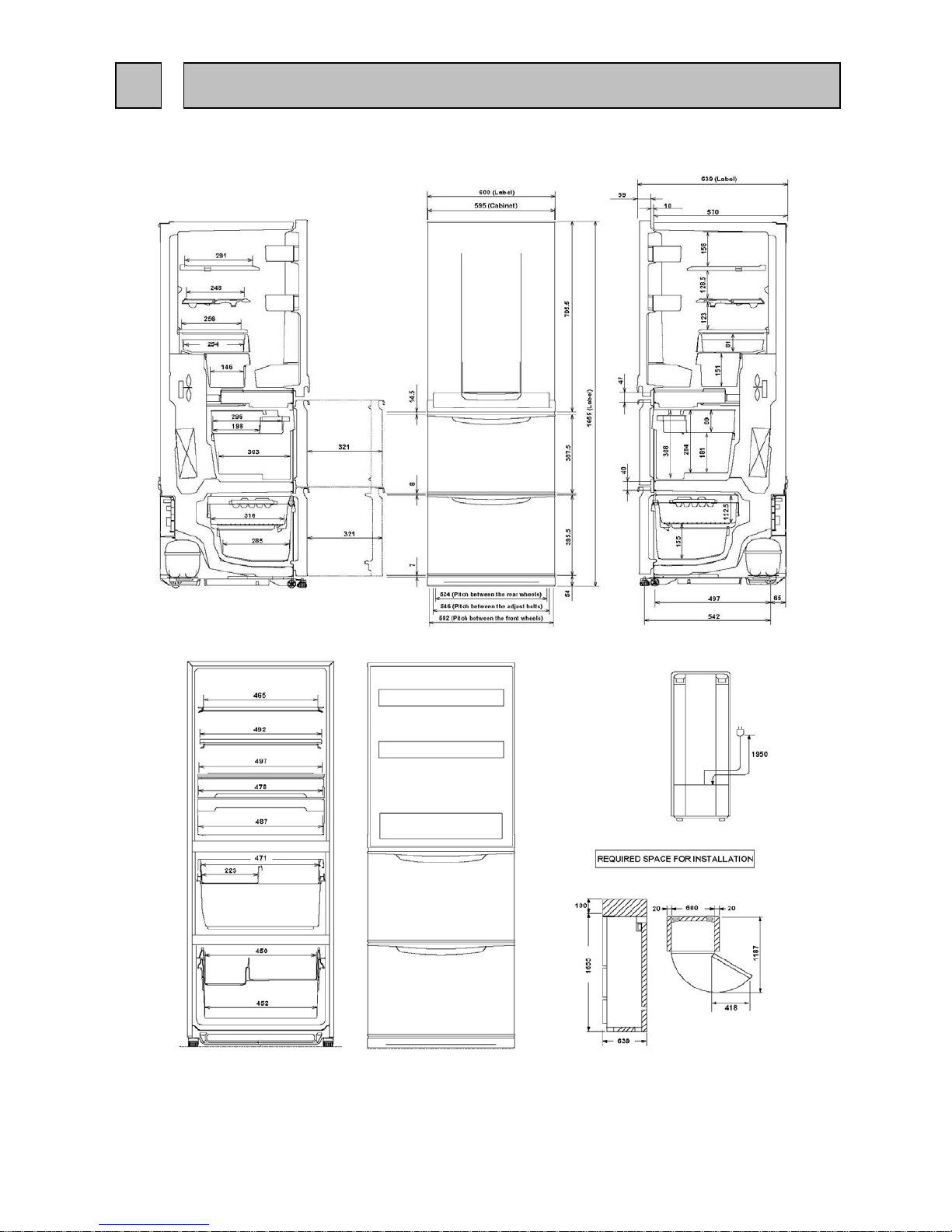
1-1 SPECIFICATIONS
MR-CU375S/SL-A
MR-CU375S/SL-A(NZ)
Power supply
Total capacity L
Dimensions (HXWXD) mm. 1655 x 600 x 639
Cabinet Acrylic resin coated steel
Food liner ABS resin
Cabinet Foamed cyclopenthane
Refrigerator door Foamed cyclopenthane
Vegetable door Foamed cyclopenthane
Freezer door Foamed cyclopenthane
Cooling system
Freezer Forced air convection
Refrigerator 3 way air flow
Evaporator Fin and tube type
Condenser Concealed type
Defrost system Automatic (Defrost heater )
Drain Automatic (drainage)
Temperature control system Automatic control
Refrigerator room light 240V, 15W (E12)
Ice spoon 1 pc.
Slide chilled case (UP) 1 pc.
Slide chilled case (LR) 1 pc.
Freezing case (UP)
1 pc.
Freezing case (LOW)
1 pc.
Crystal shelf (R)
1 pc.
Top plate
1 pc.
Slide shelf
1 pc.
Free pocket (M) 2 pcs.
Tube stand 1 pc.
Egg case 1 pc.
Bottle pocket 1 pc.
Vegetable case 1 pc.
Vegetable case cover
1 pc.
Drain pan 1 pc.
Fruit case 1 pc.
Water tank 1 pc.
Kick plate 1 pc.
Weight
Unit kg 69
Shipping kg 76
1 SPECIFICATIONS
- 1 -
Insulation
Accessories
GROSS (AS) 376 (R : 198 V : 111 F : 67)
230-240V 50Hz
1-2 ELECTRICAL PARTS SPECIFICATION
MR-CU375S/SL-A
MR-CU375S/SL-A(NZ)
Model ESS60C11RAW
Power supply 220-240V, 50Hz
Compresso
r
Rated input W 116/118 (220/240V 50Hz)
Starting current A 8.49/9.31 (220/240V 50Hz)
Running current A 0.57/0.55 (220/240V 50Hz)
Winding resistance (A.T. 20
o
C)
17.9
Ω(Main) / 15.1 Ω(Aux)
PTC RELAY PTH7M330MD2
Model 5TM222NHBYY-53
Motor protecto
r
Ambient temperature
o
C
25
Time Sec. 16 MAX
Current A 6.7
Running capacito
r
4µF 400VAC
Capillary tube mm.
∅ 1.8 X ∅ 0.65 X 2350
Dehydrant Molecular sieve g 10
Refrigerant HFC. 134a g 220
Compressor oil g
Defrosting timer Control board
Defrost finish
o
C
Thermister 14 +
1.5
Thermal fuse
o
C
73
Defrost heater
Not equipped
Model UDQM002B3
Type DC brushless
Number of poles 10P
Input W 2.4 (12V DC)
Revolution r.p.m 1520(12V DC)
Model UDQM004B3
Type DC brushless
Number of poles 10P
Input W 1 (12V DC)
Revolution r.p.m 1200(12V DC)
Vegetable case heate
r
W6
Water pipe heate
r
W0.9
Drain pipe heate
r
W6
Freeze
r
Refrigerato
r
Dial position ON OFF OPEN SHUT
LOW
o
C
-16.0 -21.9 7.0 5.8
MID
o
C
-18.4 -24.3 5.1 3.8
HI
o
C
-21.1 -27.1 3.2 1.9
186 (FREOL ∝ 10)
Refrigerator
384 Ω (240V, 150W)
- 2 -
Defrosting control
Deodorizing function of defrost heater
Thermistor RThermistor F
Fan motor
Heater
Machine
Chamber
Temperature control
MR-CU375S/SL-A
Unit : mm
MR-CU375S/SL-A(NZ)
- 3 -
2 OUTLINES AND DIMENSIONS
MR-CU375S/SL-A
(SKELETON WIRING DIAGRAM)
MR-CU375S/SL-A(NZ)
3 WIRING DIAGRAM
- 4 -
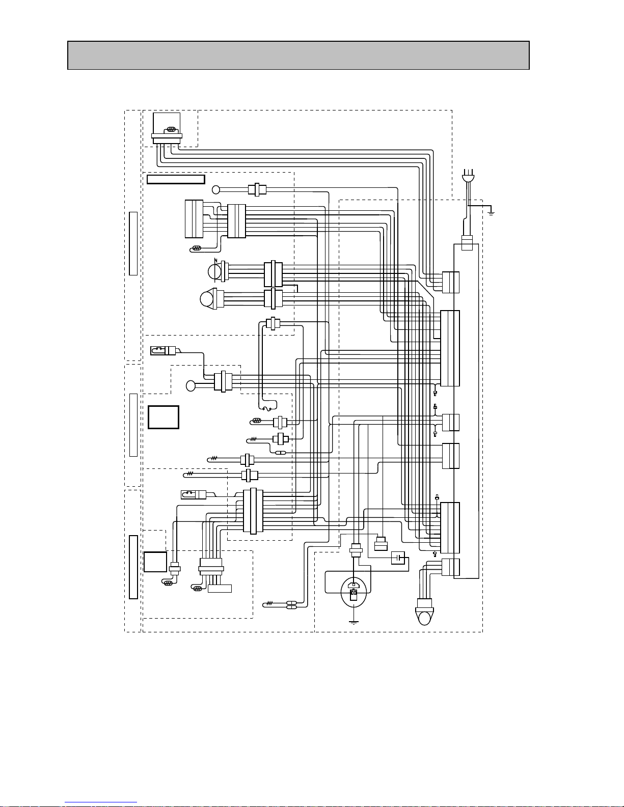
(ACTUAL WIRING DIAGRAM)
Remark GY = GRAY BK = BLACK BR = BROWN
W = WHITE OR = ORANGE
R = RED Y = YELLOW
SB = SKY BLUE YG = YELLOW GREEN
P = PINK LG = LIGHT GREEN
LB = LIGHT BROWN BY = BRIGHT YELLOW
V = VIOLET B = BLUE
- 5 -
THERMALFUSE(73°
7 6 5 4 3 2 1
LL
BUZZER&
THERMISTORA.T
REFRIGERATORROOM
9
8
7
6
5
4
3
2
1
R
Y
SB
GY
BY
BK
8
7
6
5
4
3
2
1
R
Y
SB
GY
BY
BK
W
W
R
Y
SB
GY
BY
BK
OR
SB
THERMISTORR
MOTORDAMPER
MD
1
2
3
4
1
2
3
4
R
Y
B
BR
1
2
3
4
5
6
R
Y
B
BR
R
Y
B
BR
FM
FANMOTOR
BK
V
LB
BY
1
2
3
4
BK
V
LB
BY
BK
V
LB
BY
ROOMLIGHT
1
2
YORY
GY
2
1
GY
W
GY
W
4
3
2
1
1
2
LB
LB
LB
LB
LB
LB
R
B
YG
P
M
WATERPUMP
DOORSW.R
C)
VEGETABLE
ROOM
DEF.THERMISTOR
DEF.HEATER
1
2
1
W
W
W
W
P
SB
R
WATERPIPEHEATER
1
2
1
2
1
2
3
4
5
6
7
8
9
10
1
2
LB
LB
LB
LB
LB
R
GY
R
GY
YG
SBBK
BK
SB
SB
SB
SB
SB
SB
SB
B
B
LG
LG
GY
GY
W
W
P
P
VHEATER
DOORSW.F
FREEZER
ROOM
THERMISTORF
THERMISTORI
GEARBOX
6 5 4 3 2 12 1
DRAIN
HEATER
WW
B
SB
W
GYGY
W
PTC
THERMISTOR
OUTER
FANMOTOR
1 2 3 4
Y
GY
GY
Y
MOTORPROTECTOR
FM
V
BK
OR
LG
4
3
2
1
CN10
12
11
10
9
8
7
6
5
4
3
2
1
V
BK
GY
B
BY
BR
LB
Y
P
R
W
YG
CN4
11
9
7
5
3
1
YG
SB
Y
7
5
3
1
R
W
GY
18
17
16
15
14
13
12
11
10
9
8
7
6
5
4
3
2
1
SB
LB
P
LG
OR
SB
B
Y
R
BY
GY
BK
V
GY
R
W
5
4
3
2
1
3 1
B
BR
CN3
CN2
CN7
CN9
CN1
R
W
V
GY
SB
TEMPCONTROL
W
V
W
V
W
REFRIGERATORDOOR
LG
OR
BK
V
1
2
GY
GY
W
W
2
1
R
DIODE
W
CONTROLBOARD
VEGETABLEDOOR
FREEZERDOOR
W
R
P
SB
YB
W
W
SBLGGY
MR-CU375S/SL-A
MR-CU375S/SL-A(NZ)
MR-CU375S/SL-A
MR-CU375S/SL-A(NZ)
- 6 -
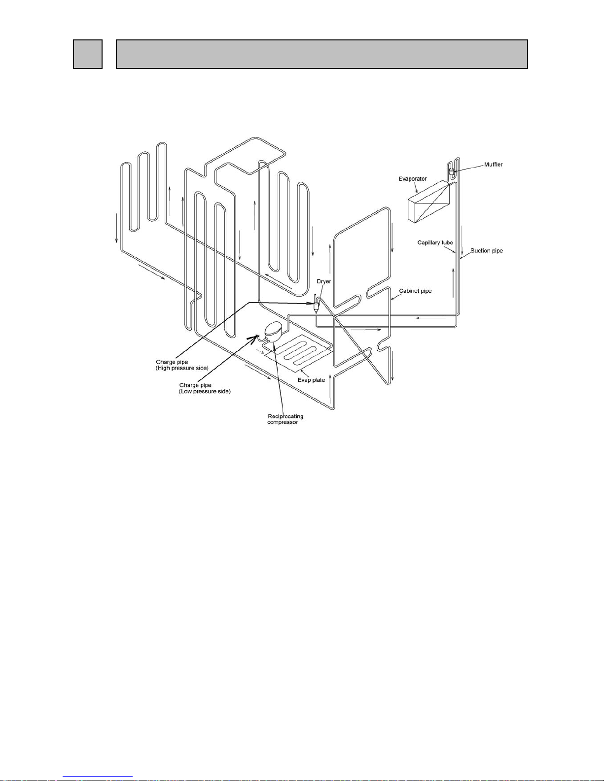
4 REFRIGERANT CIRCUIT
MR-CU375S/SL-A
MR-CU375S/SL-A(NZ)
- 7 -
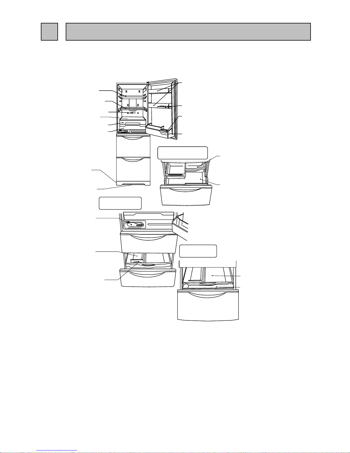
5 NAMES OF PARTS
Fruit case
Vegetable case
Water tank
Ice box sheet
Ice spoon
Freezing case (UP)
Freezing case (LOW)
Vegetable case room
Auto ice making
Freezer room
Free pocket (M)
Egg case
Tube stand
Bottle pocket
Crystal shelf (R)
Slide shelf
Thermo dial (R)
Slide Chilled case (UP)
Slide chilled case (LOW)
Top plate
Kick plate
Drain pan
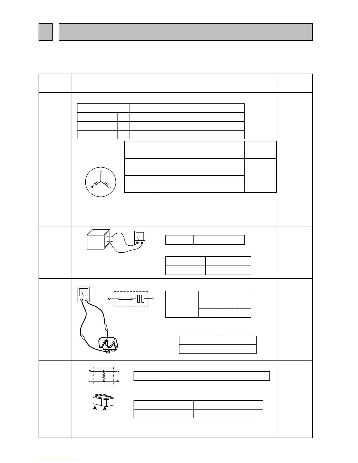
6.1 TROUBLE CRITERION OF MAIN PARTS
MR-CU375S/SL-A
MR-CU375S/SL-A(NZ)
Compressor
Measure the resistance with a tester.
(Ambient temperature:Room temperature 15
o
C ~ 25oC)
Measure the resistance with a teste
r
Open
Close
Opened (∞ Ω )
PTC Relay
PTH7M330MD2
Measure the resistance with a tester.
(Ambient temperature:Room temperature 15
o
C ~ 25oC)
Normal
As PTC Relay has been heated while refrigerator is running be sure
to measure the resistance after the thermistor has got cool enough.
33 Ω (Approx.)
Abnormal(faulty)
Opened (∞ Ω ) or Short (0Ω)
Rated input W 116/118 (220/240V 50Hz)
Short (0Ω )
15.1 Ω (Approx.)
Normal
Main wiring
A
Starting current
chamber at the
rear side of
0.57/0.55 (220/240V 50Hz)
A 8.49/9.31 (220/240V 50Hz)
Running current
Measure the resistance with a tester.(Ambient
temperature:Room temperature 15
o
C ~ 25oC)
69 + 9o C
Abnormal
(faulty)
5TM222NHBYY-53
Opened
(∞ Ω )
or
Short (0Ω)
120 +
5o C
Connected
Point
Normal
17.9 Ω (Approx.)
Auxilliary wiring
Run capacitor
4 µF
Rated input
Motor
protector
400VAC
Abnormal(faulty)
Model
the frame
the frame
In the control
panel of the
rear side at
compressor
room
Compressor in
the machine
chamber at the
rear side of
the frame
- 8 -
Model
Normal
Abnormal(faulty)
Less than 1Ω
rear side of
chamber at the
the machine
Compressor in
6
Components
/ Part Name
TROUBLE SHOOTING
Model
Parts
Mounted
Position
Check Method and Criterion
ESS60C11RAW (220-240V 50Hz)
Compressor in
the machine
Auxilialy
wiring
Main
wiring
5
6
3
2
5
6
2
3
1
3
Therminal check point
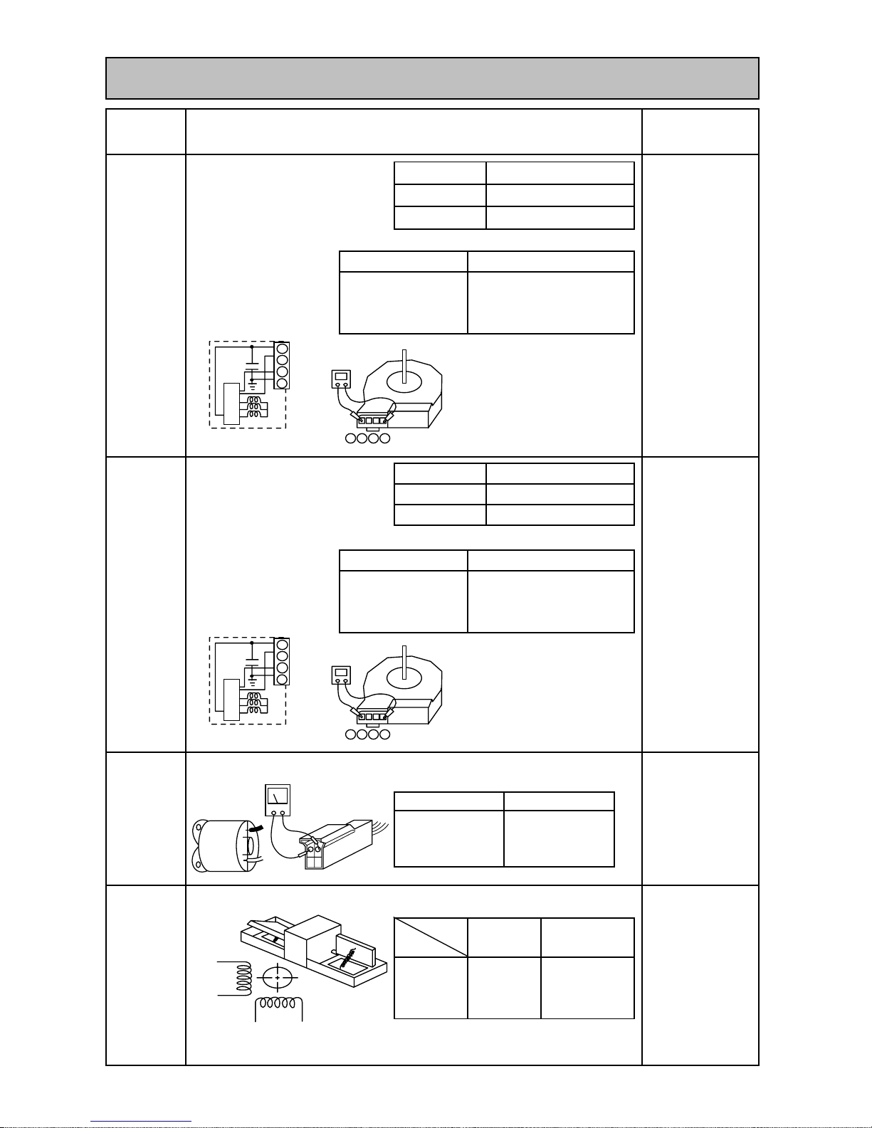
Measure the resistance with a tester.(Ambient temperature: Room temperature 15oC ~ 25oC)
Measure the resistance with a tester.(Ambient temperature: Room temperature 15
o
C ~ 25oC)
Measure the resistance with a tester.(Ambient temperature: Room temperature 15
o
C ~ 25oC)
Normal
Abnormal (faulty)
Measure the resistance with a tester.(Ambient temperature: Room temperature 15oC ~ 25oC)
Number of pole
DC brushless
Diameter
∅ 140 (Diagonal fan)
In the machine
chanber at the rear
side of the frame.
UDQM004B3
Model
Number of pole
DC brushless
Diameter
∅ 140 (Diagonal fan)
Open (∞Ω) or
short circuit (0Ω)
Motor
damper for
refrigerator
compartment
slide
compartment
In the fan grille of
the refrigerator
compartment.
Normal
415 Ω
(Approx.)
Model
Normal
Between 1 - 4 (GND
and IC Power ) :
About 12k Ω
- 9 -
Under the water
tank holder in
refrigerator
compartment.
Open (∞ Ω )
or short
circuit (0Ω)
Abnormal
(faulty)
Winding
(Blue-White,
Red-Yellow)
Water
pump motor
(DC 5V)
16 Ω (Approx.)
In the fan grille of
the refrigerator
compartment.
Refrigerator
fan motor
UDQM002B3
Machine
chamber
fan motor
Normal
Abnormal (faulty)
B
etween 1 - 4
(GND and IC
Power ) : About
9
k Ω
Between 1-4 : open( ∞
Ω ) or
between 3-4 : short ( 0 Ω)
Abnormal (faulty)
Between 1-4 : open( ∞
Ω ) or
between 3-4 : short ( 0 Ω)
Check Method and Criterion
Parts Mounted Position
Components/
Part Name
IC power
Power
GND
FG
IC
Pin no.
1
2
3
4
123
4
IC power
Power
GND
FG
IC
Pin no.
1
2
3
4
123
4
Yellow
Red
Blue Brown
 Loading...