

Mitsubishi Electric MELSERVO-J4, MR-CV, MR-J4-B(-RJ), MR-CR55K(4), MR-J4-B-RJ010 Instruction Manual
...
General-Purpose AC Servo
MELSERVO-J4 Servo amplifier
INSTRUCTION MANUAL (TROUBLE SHOOTING)
M
Safety Instructions
Please read the instructions carefully before using the equipment.
To use the equipment correctly, do not attempt to install, operate, maintain, or inspect the equipment until
you have read through this Instruction Manual, Installation guide, and appended documents carefully. Do not
use the equipment until you have a full knowledge of the equipment, safety information and instructions.
In this Instruction Manual, the safety instruction levels are classified into "WARNING" and "CAUTION".
WARNING
CAUTION
Note that the CAUTION level may lead to a serious consequence according to conditions.
Please follow the instructions of both levels because they are important to personnel safety.
What must not be done and what must be done are indicated by the following diagrammatic symbols.
Indicates that incorrect handling may cause hazardous conditions,
resulting in death or severe injury.
Indicates that incorrect handling may cause hazardous conditions,
resulting in medium or slight injury to personnel or may cause physical
damage.
Indicates what must not be done. For example, "No Fire" is indicated by .
Indicates what must be done. For example, grounding is indicated by .
In this Instruction Manual, instructions at a lower level than the above, instructions for other functions, and so
on are classified into "POINT".
After reading this Instruction Manual, keep it accessible to the operator.
A - 1
1. To prevent electric shock, note the following
WARNING
Before wiring or inspection, turn off the power and wait for 15 minutes or more (20 minutes or more for
converter unit) until the charge lamp turns off. Then, confirm that the voltage between P+ and N(between L+ and L- for converter unit) is safe with a voltage tester and others. Otherwise, an electric
shock may occur. In addition, always confirm whether the charge lamp is off or not from the front of the
servo amplifier (converter unit).
Do not operate switches with wet hands. Otherwise, it may cause an electric shock.
2. To prevent fire, note the following
CAUTION
When you use an MR-J4 multi-axis servo amplifier, connecting an encoder for wrong axis to the CN2A,
CN2B, or CN2C connector may cause a fire.
3. To prevent injury, note the following
CAUTION
The servo amplifier (drive unit), converter unit heat sink, regenerative resistor, servo motor, etc. may
become hot while power is on or for some time after power-off. Take safety measures, e.g. provide
covers, to avoid accidentally touching the parts (cables, etc.) by hand.
4. Additional instructions
The following instructions should also be fully noted. Incorrect handling may cause a malfunction, injury,
electric shock, etc.
(1) Wiring
CAUTION
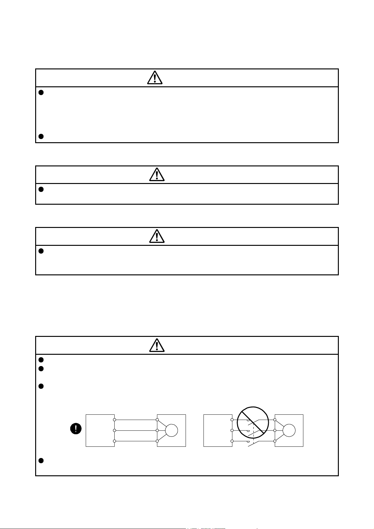
Wire the equipment correctly and securely. Otherwise, the servo motor may operate unexpectedly.
To avoid a malfunction of the servo motor, connect the wires to the correct phase terminals (U/V/W) of
the servo amplifier (drive unit) and the servo motor.
Connect the servo amplifier (drive unit) power output (U/V/W) to the servo motor power input (U/V/W)
directly. Do not let a magnetic contactor, etc. intervene. Otherwise, it may cause a malfunction.
Servo amplifier
(drive unit)
U
V
W
Servo motor
U
V
W
M
Servo amplifier
(drive unit)
U
V
W
Servo motor
U
V
W
M
Configure a circuit to turn off EM2 or EM1 when the main circuit power is turned off to prevent an
unexpected restart of the servo amplifier (drive unit).
A - 2
(2) Usage
CAUTION
Before resetting an alarm, make sure that the run signal of the servo amplifier (drive unit) is off in order to
prevent a sudden restart. Otherwise, it may cause an accident.
Use the servo amplifier (drive unit) and converter unit with the specified servo motor.
(3) Corrective actions
CAUTION
Ensure safety by confirming the power off, etc. before performing corrective actions. Otherwise, it may
cause an accident.
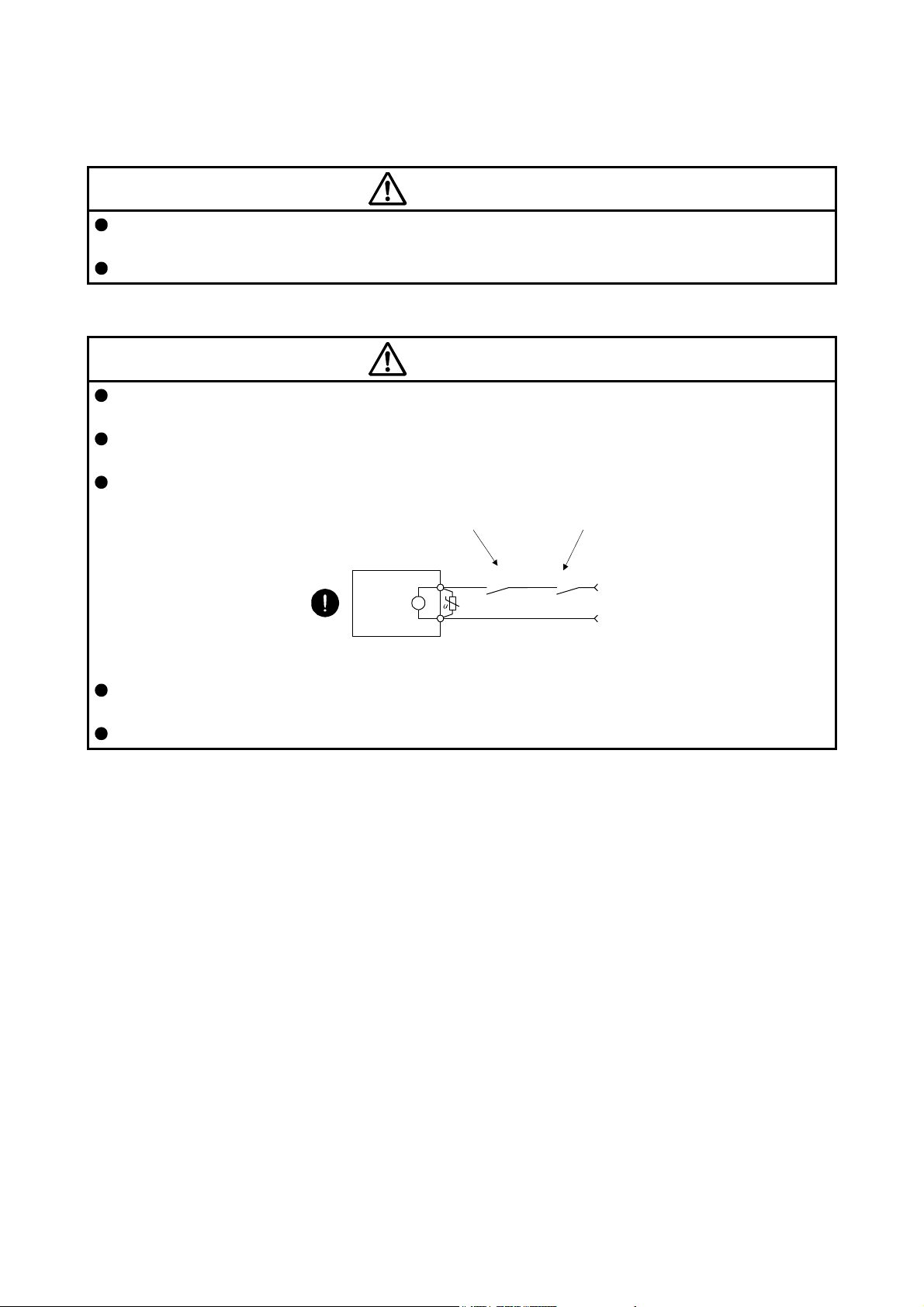
When it is assumed that a hazardous condition may occur due to a power failure or product malfunction,
use a servo motor with an electromagnetic brake or external brake to prevent the condition.
Configure an electromagnetic brake circuit which is interlocked with an external emergency stop switch.
Contacts must be opened when CALM (Common
malfunction) or MBR (Electromagnetic brake
interlock) turns off.
Contacts must be opened with
the emergency stop switch.
Servo motor
B
Electromagnetic brake
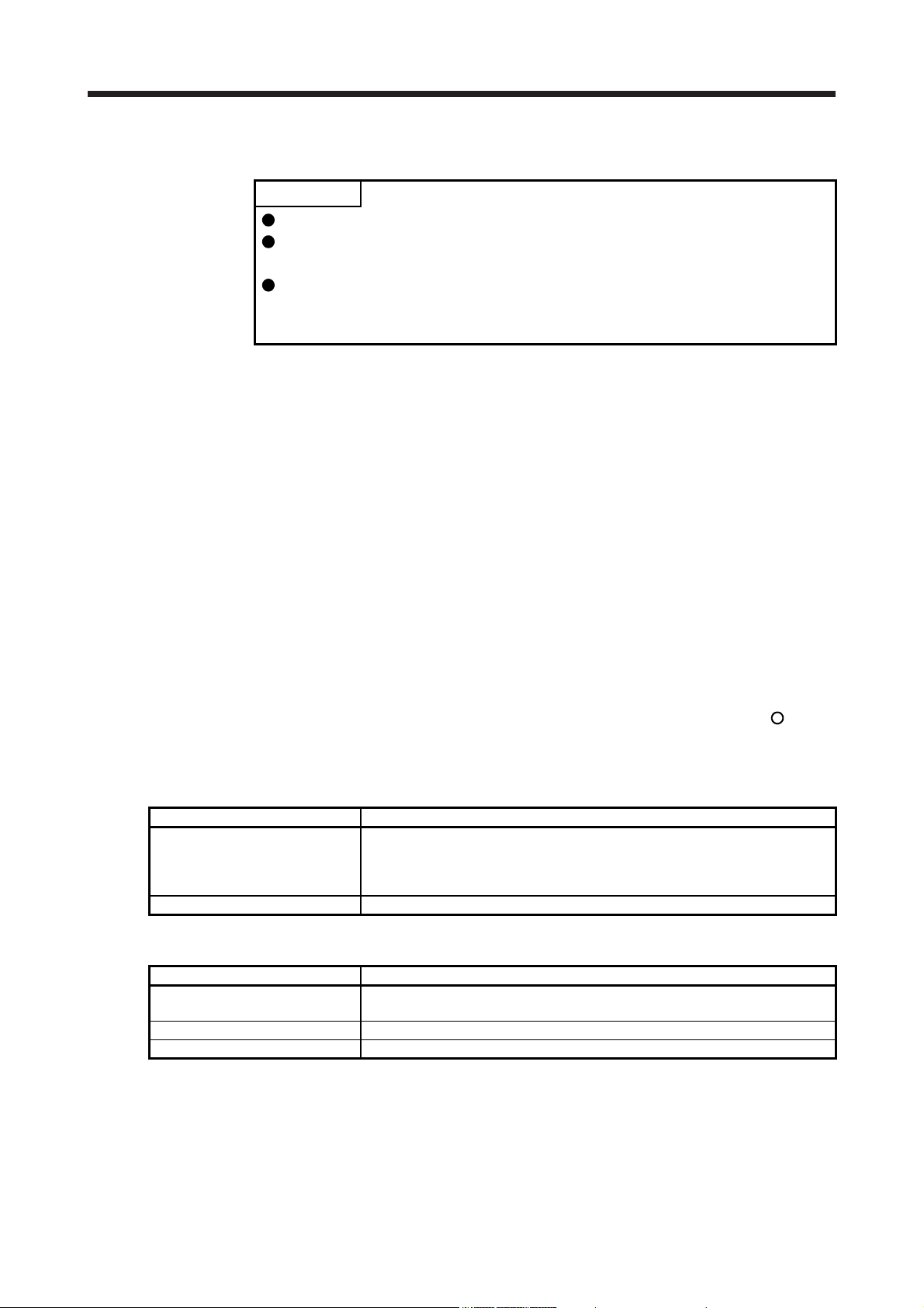
When any alarm has occurred, eliminate its cause, ensure safety, and deactivate the alarm before
restarting operation.
Provide an adequate protection to prevent unexpected restart after an instantaneous power failure.
RA
24 V DC
A - 3

«About the manual»
This Instruction Manual covers the following models. These include servo amplifiers (drive units) which
have optional units.
MR-J4-_A/MR-J4-_A4/MR-J4-_A1/MR-J4-_A-RJ/MR-J4-_A4-RJ/MR-J4-_A1-RJ
MR-J4-_B/MR-J4-_B4/MR-J4-_B1/MR-J4-_B-RJ/MR-J4-_B4-RJ/MR-J4-_B1-RJ
MR-J4W_-_B
MR-J4-_B-RJ010/MR-J4-_B4-RJ010
MR-J4-03A6/MR-J4-03A6-RJ/MR-J4W2-0303B6
MR-J4-_GF/MR-J4-_GF4/MR-J4-_GF-RJ/MR-J4-_GF4-RJ
MR-J4-DU_A/MR-J4-DU_A4/MR-J4-DU_A-RJ/MR-J4-DU_A4-RJ
MR-J4-DU_B/MR-J4-DU_B4/MR-J4-DU_B-RJ/MR-J4-DU_B4-RJ
MR-CV_
MR-CR55K/MR-CR55K4
The symbols in the target column mean as follows.
[A]: MR-J4-_A/MR-J4-_A4/MR-J4-_A1/MR-J4-_A-RJ/MR-J4-_A4-RJ/MR-J4-_A1-RJ/MR-J4-DU_A/
MR-J4-DU_A4/MR-J4-DU_A-RJ/MR-J4-DU_A4-RJ/MR-J4-03A6/MR-J4-03A6-RJ
[B]: MR-J4-_B/MR-J4-_B4/MR-J4-_B1/MR-J4-_B-RJ/MR-J4-_B4-RJ/MR-J4-_B1-RJ/
MR-J4-DU_B/MR-J4-DU_B4/MR-J4-DU_B-RJ/MR-J4-DU_B4-RJ
[WB]: MR-J4W_-_B/MR-J4W2-0303B6
[RJ010]: MR-J4-_B-RJ010/MR-J4-_B4-RJ010
[GF]: MR-J4-_GF/MR-J4-_GF4/MR-J4-_GF-RJ/MR-J4-_GF4-RJ
[Other]: For manufacturer adjustment
A - 4

CONTENTS
1. TROUBLESHOOTING FOR SERVO AMPLIFIER (DRIVE UNIT) 1- 1 to 1-130
1.1 Explanation for the lists ..................................................................................................................... 1- 1
1.2 Alarm list ........................................................................................................................................... 1- 3
1.3 Warning list ...................................................................................................................................... 1-13
1.4 Remedies for alarms ........................................................................................................................ 1-16
1.5 Remedies for warnings .................................................................................................................... 1-92
1.6 Trouble which does not trigger alarm/warning .............................................................................. 1-116
1.7 Network module error codes.......................................................................................................... 1-129
2. TROUBLESHOOTING FOR MR-CV_POWER REGENERATION CONVERTER UNIT 2- 1 to 2- 8
2.1 Explanations of the lists .................................................................................................................... 2- 1
2.2 Alarm list ........................................................................................................................................... 2- 1
2.3 Warning list ....................................................................................................................................... 2- 2
2.4 Remedies for alarms ......................................................................................................................... 2- 2
2.5 Remedies for warnings ..................................................................................................................... 2- 7
3. TROUBLESHOOTING FOR MR-CR55K(4) RESISTANCE REGENERATION CONVERTER UNIT 3- 1 to 3-10
3.1 Explanation for the lists ..................................................................................................................... 3- 1
3.2 Alarm/warning list .............................................................................................................................. 3- 1
3.3 Remedies for alarms ......................................................................................................................... 3- 2
3.4 Remedies for warnings ..................................................................................................................... 3- 8
4. DRIVE RECORDER 4- 1 to 4-10
4.1 How to use drive recorder .................................................................................................................. 4- 1
4.2 How to display drive recorder information ........................................................................................ 4-10
APPENDIX App.- 1 to App.- 1
App. 1 Detection points of [AL. 25], [AL. 92], and [AL. 9F] ............................................................... App.- 1
1

MEMO
2
1. TROUBLESHOOTING FOR SERVO AMPLIFIER (DRIVE UNIT)
1. TROUBLESHOOTING FOR SERVO AMPLIFIER (DRIVE UNIT)
POINT
As soon as an alarm occurs, turn SON (Servo-on) off and interrupt the power.
[AL. 37 Parameter error] and warnings (except [AL. F0 Tough drive warning])
are not recorded in the alarm history.
[AL. 8D.1 CC-Link IE communication error 1] and [AL. 8D.2 CC-Link IE
communication error 2] are not recorded in the alarm history. For MR-J4-_GF_(RJ), these alarms are recorded by setting [Pr. PN06] to "_ _ _ 1".
When an error occurs during operation, the corresponding alarm or warning is displayed. When an alarm is
displayed, refer to section 1.4 and take the appropriate action. When an alarm occurs, ALM will turn off.
When an warning is displayed, refer to section 1.5 and take the appropriate action.
1.1 Explanation for the lists
(1) No./Name/Detail No./Detail name
Indicates each No./Name/Detail No./Detail name of alarms or warnings.
(2) Stop method
For the alarms and warnings in which "SD" is written in the stop method column, the servo motor stops
with the dynamic brake after forced stop deceleration. For the alarms and warnings in which "DB" or
"EDB" is written in the stop method column, the servo motor stops with the dynamic brake without forced
stop deceleration.
(3) Alarm deactivation
After its cause has been removed, the alarm can be deactivated in any of the methods marked
in the
alarm deactivation column. Warnings are automatically canceled after the cause of occurrence is
removed. Alarms are deactivated with alarm reset, CPU reset, or cycling the power.
(a) MR-J4-_A_(-RJ)/MR-J4-DU_A_(-RJ)
Alarm reset 1. Turning on RES (Reset) with input device
Cycling the power Turning the power off and then turning it on again.
Alarm deactivation Explanation
2. Pushing the "SET" button while the display of the servo amplifier is the current
alarm display status
3. Click "Occurring Alarm Reset" in the "Alarm Display" window of MR Configurator2
(b) MR-J4-_B_(-RJ010)/MR-J4W_-_B/MR-J4-DU_B_(-RJ)/MR-J4-_GF_(-RJ)
Alarm reset 1. Reset command from controller
CPU reset Resetting the controller itself
Cycling the power Turning the power off and then turning it on again.
Alarm deactivation Explanation
2. Click "Occurring Alarm Reset" in the "Alarm Display" window of MR Configurator2
(4) Processing system (only for MR-J4W_-_B_)
Processing system of alarms is as follows.
Each axis: Alarm is detected for each axis.
Common: Alarm is detected as the whole servo amplifier.
1 - 1

1. TROUBLESHOOTING FOR SERVO AMPLIFIER (DRIVE UNIT)
(5) Stop system (only for MR-J4W_-_B_)
This means target axis to stop when the alarm occurs.
Each axis: Only alarming axis will stop.
All axes: All axes will stop.
(6) Alarm code (only MR-J4-_A_(-RJ)/MR-J4-DU_A_(-RJ))
To output alarm codes, set [Pr. PD34] to "_ _ _ 1" when using an MR-J4-_A_(-RJ)/MR-J4-DU_A_(-RJ).
Alarm codes are outputted by on/off of bit 0 to bit 2. Warnings ([AL. 90] to [AL. F3]) do not have alarm
codes. The alarm codes in the following table will be outputted when they occur. The alarm codes will
not be outputted in normal condition.
When using an MR-D01 extension IO unit, you can output alarm codes by setting [Pr. Po12] to "_ _ _ 1".
Alarm codes are outputted by on/off of bit 0 to bit 3.
1 - 2
1. TROUBLESHOOTING FOR SERVO AMPLIFIER (DRIVE UNIT)
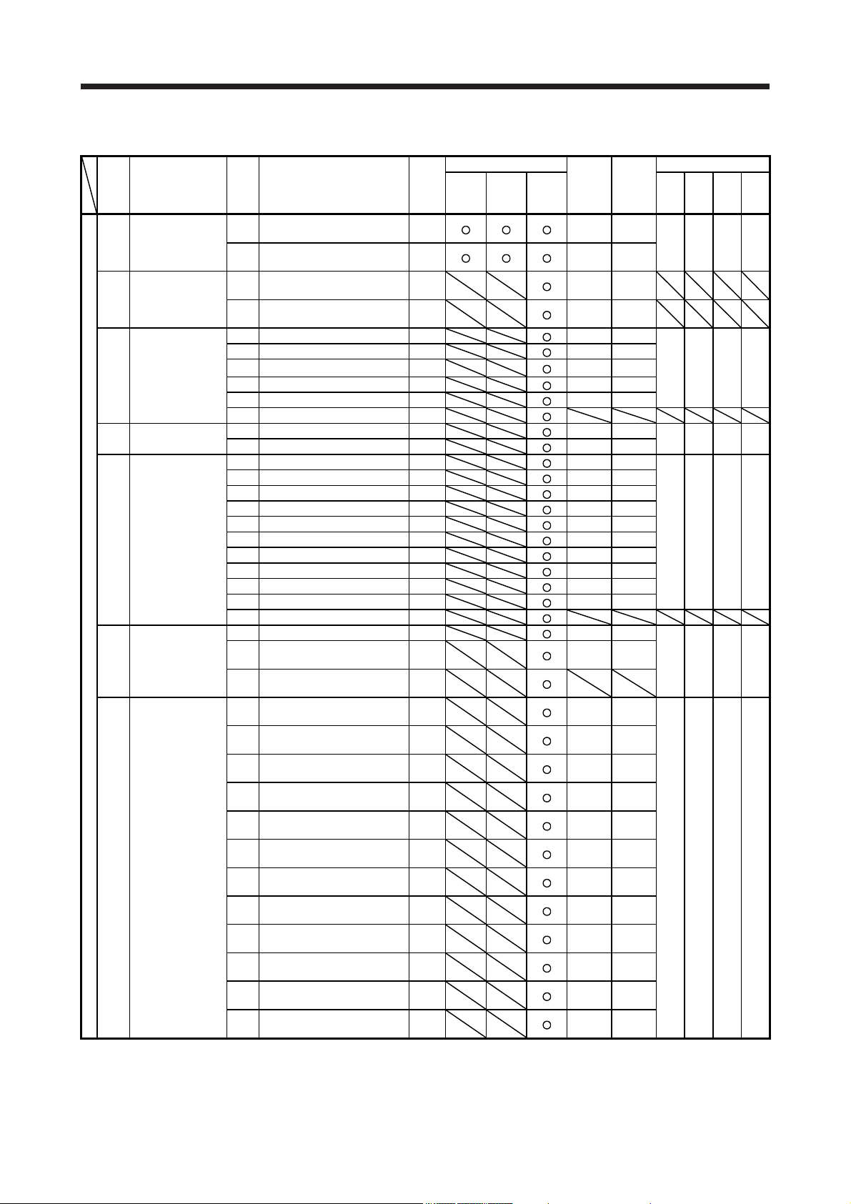
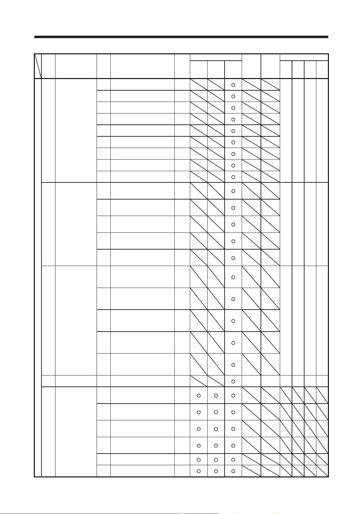
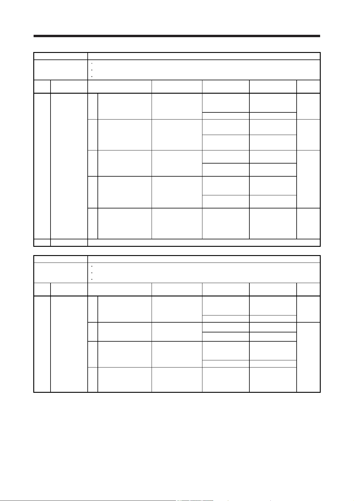
1.2 Alarm list
Stop
No. Name
Alarm
10 Undervoltage
11 Switch setting error
11.2
12.1 RAM error 1 DB
12.2 RAM error 2 DB
12.4 RAM error 4 DB
12.5 RAM error 5 DB
12.6 RAM error 6 DB
13.2 Clock error 2 DB
14.1 Control process error 1 DB
14.2 Control process error 2 DB
14.3 Control process error 3 DB
14.4 Control process error 4 DB
14 14.6 Control process error 6 DB
14.7 Control process error 7 DB
14.8 Control process error 8 DB
14.9 Control process error 9 DB
14.A Control process error 10 DB
14.B Control process error 11 DB
Memory error 1
12
13 Clock error
15
16.1
16.2
16.3
16.5
16.6
16
16.B
16.C
16.D
16.E
16.F
(RAM)
Control process
error
Memory error 2
(EEP-ROM)
Encoder initial
communication
error 1
Detail
No.
Voltage drop in the control
10.1
circuit power
Voltage drop in the main circuit
10.2
power
Axis number setting error/
11.1
Station number setting error
Disabling control axis setting
error
12.3 RAM error 3 DB
13.1 Clock error 1 DB
14.5 Control process error 5 DB
15.1 EEP-ROM error at power on DB
EEP-ROM error during
15.2
operation
Home position information read
15.4
error
Encoder initial communication Receive data error 1
Encoder initial communication Receive data error 2
Encoder initial communication Receive data error 3
Encoder initial communication Transmission data error 1
Encoder initial communication Transmission data error 2
Encoder initial communication -
16.7
Transmission data error 3
Encoder initial communication -
16.A
Process error 1
Encoder initial communication Process error 2
Encoder initial communication Process error 3
Encoder initial communication Process error 4
Encoder initial communication Process error 5
Encoder initial communication Process error 6
Detail name
method
(Note
2, 3)
EDB
SD
DB
DB
DB
DB
DB
DB
DB
DB
DB
DB
DB
DB
DB
DB
DB
DB
Alarm deactivation
Alarm
reset
CPU
reset
Process-
Cycling
system
the
(Note 9)
power
Common All axes
Common All axes
Common All axes
Common All axes
Common All axes
Common All axes
Common All axes 0 0 0 0
Common All axes
Common All axes
Common All axes
Common All axes
Common All axes
Common All axes
Common All axes
Common All axes
Common All axes
Common All axes
Common All axes
Common All axes
Common All axes
Common All axes
Common All axes
Common All axes
Each
axis
Each
axis
Each
axis
Each
axis
Each
axis
Each
axis
Each
axis
Each
axis
Each
axis
Each
axis
Each
axis
Each
axis
Stop
ing
system
(Note 9)
Each
Each
Each
Each
Each
Each
Each
Each
Each
Each
Each
Each
Alarm code (Note 8)
ACD3
(Bit 3)
0 0 1 0
0 0 0 0
0 0 0 0
0 0 0 0
axis
axis
axis
axis
axis
axis
axis
axis
axis
axis
axis
axis
0 1 1 0
ACD2
(Bit 2)
ACD1
(Bit 1)
ACD0
(Bit 0)
1 - 3
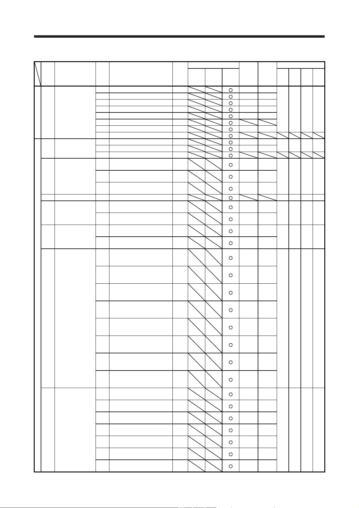
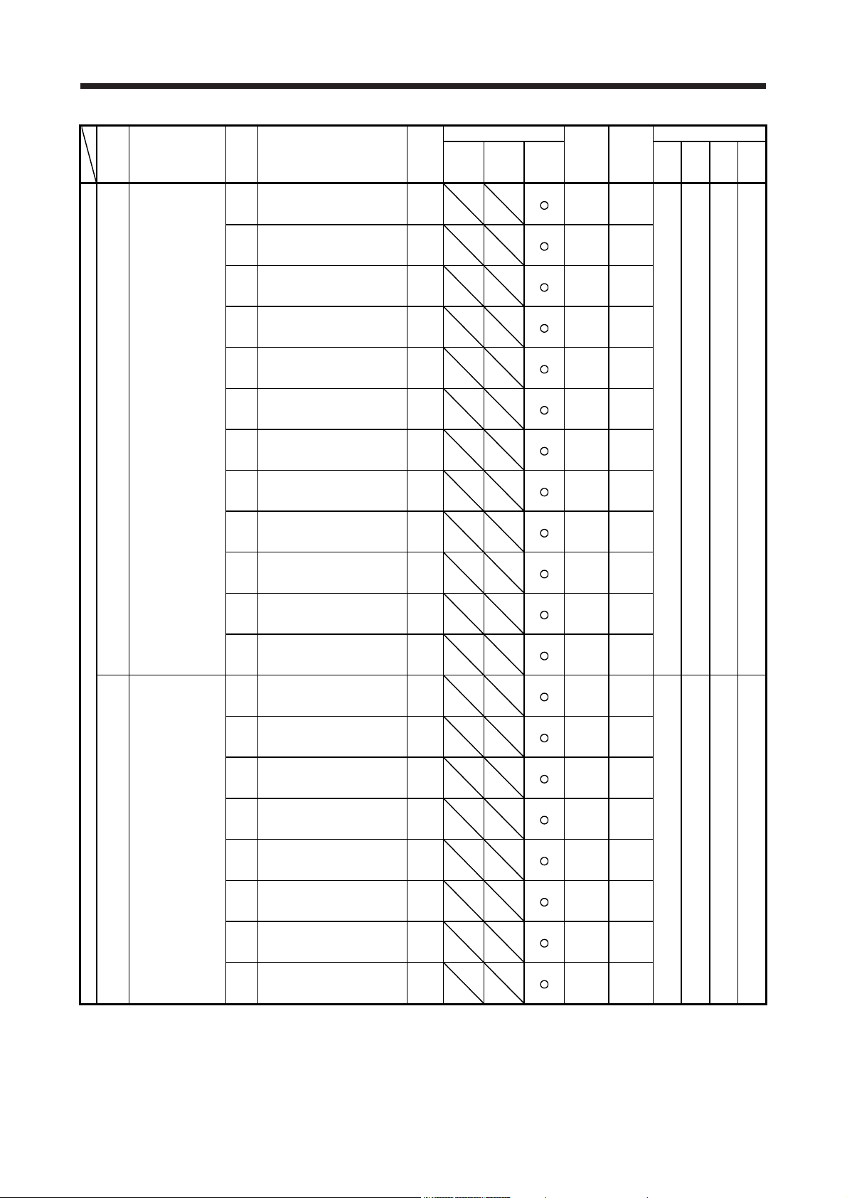
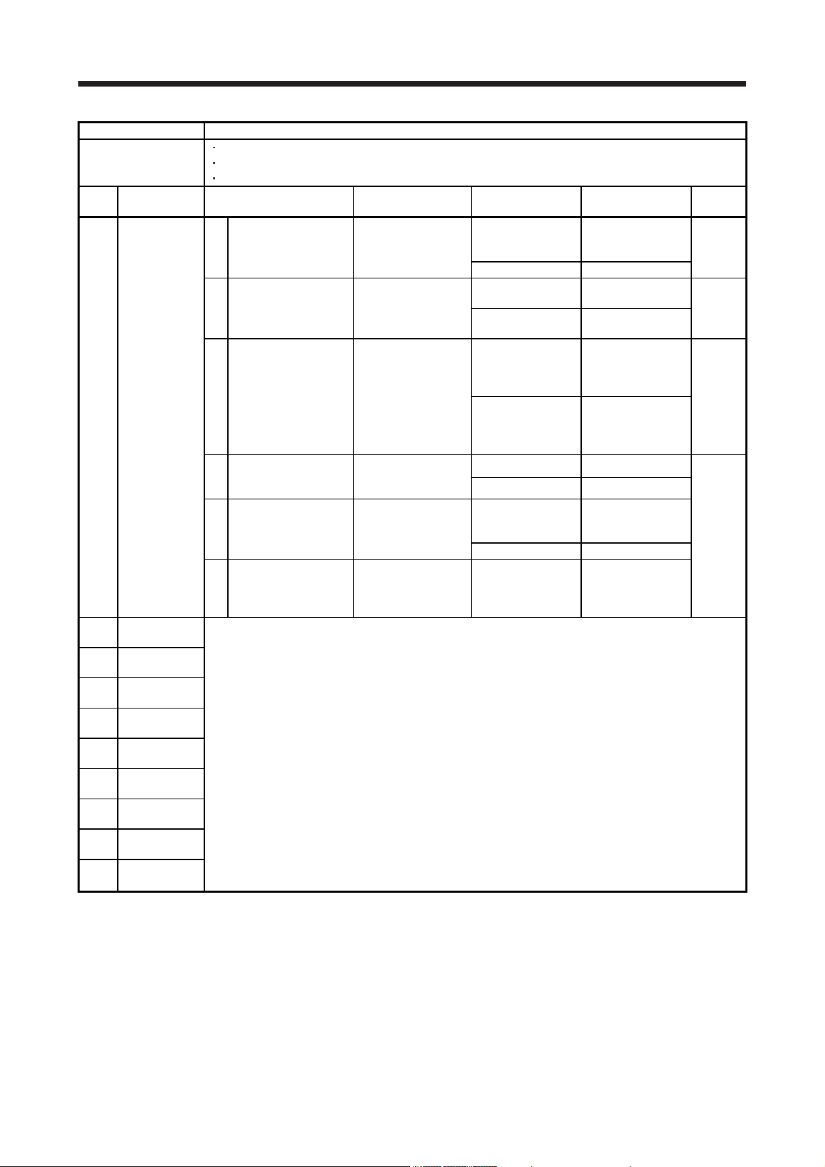
1. TROUBLESHOOTING FOR SERVO AMPLIFIER (DRIVE UNIT)
Stop
No. Name
17.1 Board error 1 DB
17.3 Board error 2 DB
Alarm
17.4 Board error 3 DB
17 Board error
17.6 Board error 5 DB
17.7 Board error 7 DB
17.8 Board error 6 (Note 6) EDB
17.9 Board error 8 DB
19 19.2 Flash-ROM error 2 DB
19.3 Flash-ROM error 3 DB
1B Converter error 1B.1 Converter unit error DB
Memory error 3
(Flash-ROM)
1A.1
1A
1E
1F
20
21 21.4 Encoder non-signal error EDB
Servo motor
combination error
1A.4
Encoder initial
communication
error 2
Encoder initial
communication
error 3
20.1
20.2
20.3
Encoder normal
communication
error 1
20.7
20.9
20.A
21.1 Encoder data error 1 EDB
21.2 Encoder data update error EDB
Encoder normal
communication
error 2
21.5 Encoder hardware error 1 EDB
21.6 Encoder hardware error 2 EDB
21.9 Encoder data error 2 EDB
Detail
No.
17.5 Board error 4 DB
19.1 Flash-ROM error 1 DB
Servo motor combination error
1
Servo motor control mode
1A.2
combination error
Servo motor combination error
2
1E.1 Encoder malfunction DB
1E.2 Load-side encoder malfunction DB
1F.1 Incompatible encoder DB
1F.2 Incompatible load-side encoder DB
Encoder normal
communication - Receive data
error 1
Encoder normal
communication - Receive data
error 2
Encoder normal
communication - Receive data
error 3
Encoder normal
20.5
communication - Transmission
data error 1
Encoder normal
20.6
communication - Transmission
data error 2
Encoder normal
communication - Transmission
data error 3
Encoder normal
communication - Receive data
error 4
Encoder normal
communication - Receive data
error 5
21.3 Encoder data waveform error EDB
Detail name
method
(Note
2, 3)
DB
DB
DB
EDB
EDB
EDB
EDB
EDB
EDB
EDB
EDB
Alarm deactivation
Alarm
reset
CPU
reset
Process-
Cycling
system
the
(Note 9)
power
Common All axes
Common All axes
Common All axes
Common All axes 0 0 0 0
Common All axes
Common All axes
Common All axes
Common All axes
Each
axis
Each
axis
Each
axis
Each
axis
Each
axis
Each
axis
Each
axis
Each
axis
Each
axis
Each
axis
Each
axis
Each
axis
Each
axis
Each
axis
Each
axis
Each
axis
Each
axis
Each
axis
Each
axis
Each
axis
Each
axis
Each
axis
Stop
ing
system
(Note 9)
0 0 1 0
ACD3
(Bit 3)
Each
axis
Each
axis
Each
axis
Each
axis
Each
axis
Each
axis
Each
axis
Each
axis
Each
axis
Each
axis
Each
axis
Each
axis
Each
axis
Each
axis
Each
axis
Each
axis
Each
axis
Each
axis
Each
axis
Each
axis
Each
axis
Each
axis
Alarm code (Note 8)
ACD2
ACD1
ACD0
(Bit 2)
(Bit 1)
(Bit 0)
0 0 0 0
0 1 1 0
0 1 1 0
0 1 1 0
0 1 1 0
0 1 1 0
1 - 4

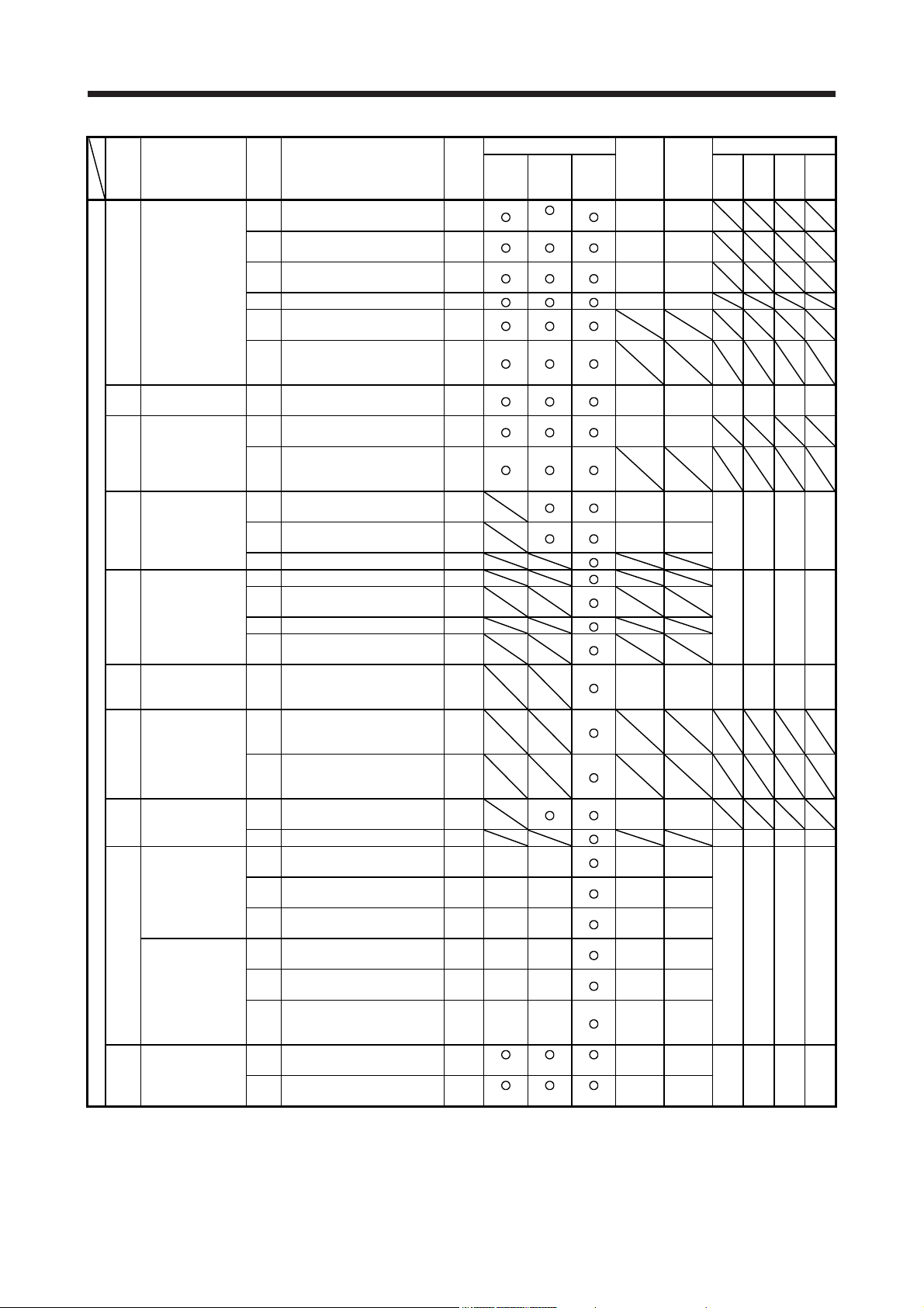
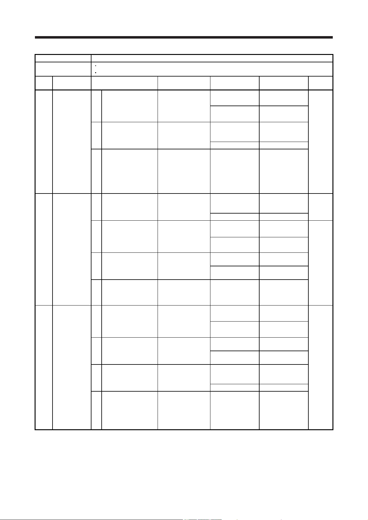
1. TROUBLESHOOTING FOR SERVO AMPLIFIER (DRIVE UNIT)
Stop
No. Name
Alarm
24 Main circuit error
33 Overvoltage 33.1 Main circuit voltage error EDB
Absolute position
25
27.1
27.2
27.3
27
27.5
27.6
27.7
28
2A.1 Linear encoder error 1-1 EDB
2A.2 Linear encoder error 1-2 EDB
2A.3 Linear encoder error 1-3 EDB
2A
2A.6 Linear encoder error 1-6 EDB
2A.7 Linear encoder error 1-7 EDB
2A.8 Linear encoder error 1-8 EDB
2B
30.1 Regeneration heat error DB
30 Regenerative error 30.2 Regeneration signal error DB
30.3
31 Overspeed 31.1 Abnormal motor speed SD
32.1
32 Overcurrent
32.4
erased
Initial magnetic
pole detection error
Linear encoder
error 2
Linear encoder
error 1
Encoder counter
error
Detail
No.
Ground fault detected by
24.1
hardware detection circuit
Ground fault detected by
24.2
software detection function
Servo motor encoder -
25.1
Absolute position erased
Scale measurement encoder -
25.2
Absolute position erased
Initial magnetic pole detection Abnormal termination
Initial magnetic pole detection Time out error
Initial magnetic pole detection Limit switch error
Initial magnetic pole detection -
27.4
Estimated error
Initial magnetic pole detection Position deviation error
Initial magnetic pole detection Speed deviation error
Initial magnetic pole detection Current error
Linear encoder - Environment
28.1
error
2A.4 Linear encoder error 1-4 EDB
2A.5 Linear encoder error 1-5 EDB
2B.1 Encoder counter error 1 EDB
2B.2 Encoder counter error 2 EDB
Regeneration feedback signal
error
Overcurrent detected at
hardware detection circuit
(during operation)
Overcurrent detected at
32.2
software detection function
(during operation)
Overcurrent detected at
32.3
hardware detection circuit
(during a stop)
Overcurrent detected at
software detection function
(during a stop)
Detail name
method
(Note
2, 3)
DB
DB
DB
DB
DB
DB
DB
DB
DB
DB
DB
EDB
DB
DB
DB
DB
DB
Alarm deactivation
Alarm
reset
(Note 1) (Note 1) (Note 1)
(Note 1) (Note 1) (Note 1)
(Note 1) (Note 1) (Note 1)
CPU
reset
Cycling
the
power
Process-
system
(Note 9)
Each
axis
Each
axis
Each
axis
Each
axis
Each
axis
Each
axis
Each
axis
Each
axis
Each
axis
Each
axis
Each
axis
Each
axis
Each
axis
Each
axis
Each
axis
Each
axis
Each
axis
Each
axis
Each
axis
Each
axis
Each
axis
Each
axis
Common All axes
Common All axes 0 0 0 1
Common All axes
Each
axis
Each
axis
Each
axis
Each
axis
Each
axis
Common All axes 1 0 0 1
Stop
ing
system
(Note 9)
All axes
All axes
All axes
All axes
All axes
All axes
ACD3
(Bit 3)
Each
axis
Each
axis
Each
axis
Each
axis
Each
axis
Each
axis
Each
axis
Each
axis
Each
axis
Each
axis
Each
axis
Each
axis
Each
axis
Each
axis
Each
axis
Each
axis
Each
axis
Each
axis
Each
axis
Each
axis
Each
axis
Alarm code (Note 8)
ACD2
ACD1
ACD0
(Bit 2)
(Bit 1)
(Bit 0)
1 1 0 0
1 1 1 0
1 1 1 0
0 1 1 0
0 1 1 0
1 1 1 0
0 1 0 1
0 1 0 0
1 - 5
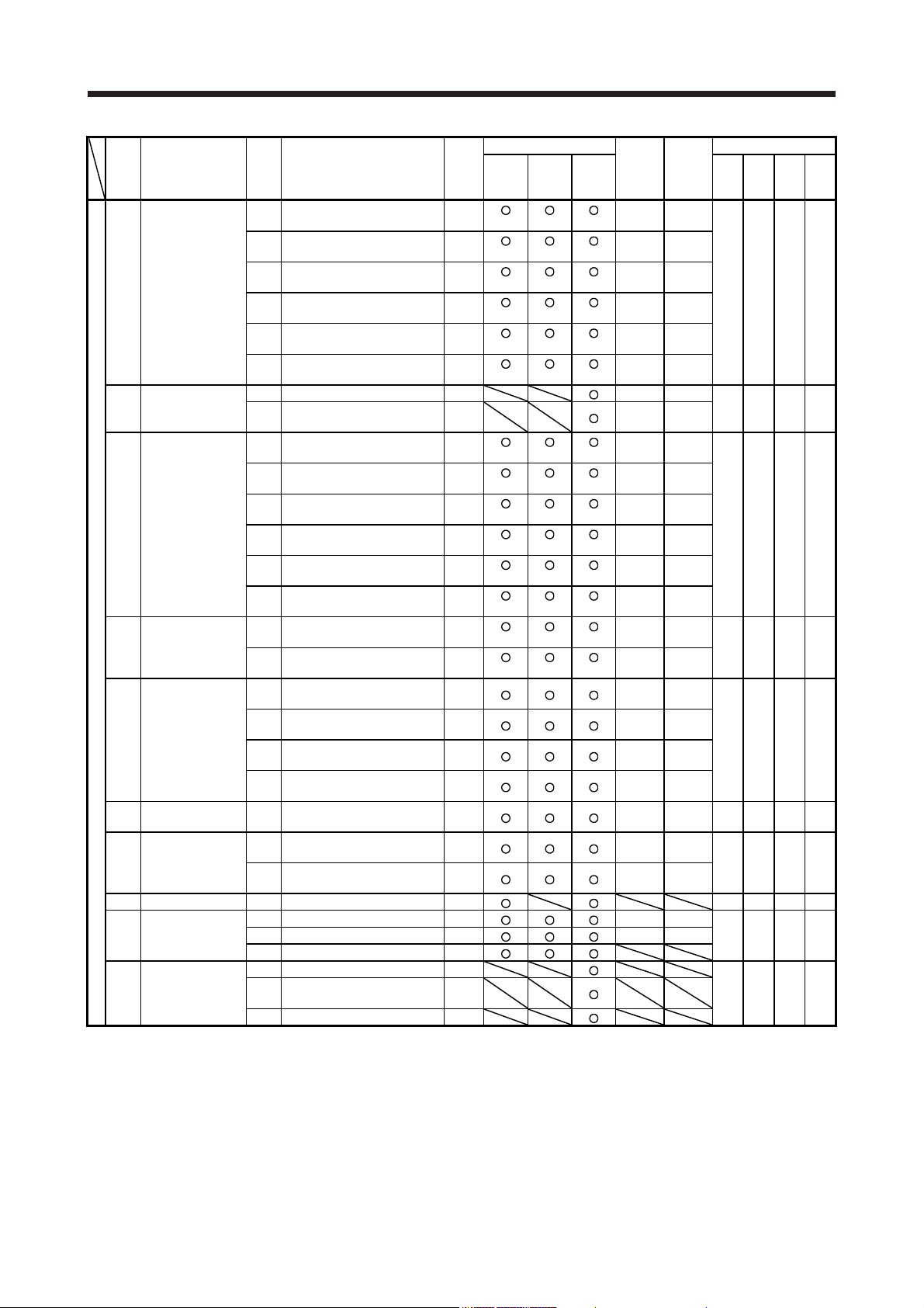
1. TROUBLESHOOTING FOR SERVO AMPLIFIER (DRIVE UNIT)
Stop
No. Name
Alarm
34.4 Hardware error signal detection SD
37.3 Point table setting error DB
39.3 Register No. error DB
3E.6 Operation mode switch error DB
SSCNET receive
34
35
36
37 Parameter error
39 Program error
3A
3D
3E
42
45
error 1
Command
frequency error
SSCNET receive
error 2
Inrush current
suppression circuit
error
Parameter setting
error for driver
communication
Operation mode
error
Servo control error
(for linear servo
motor and direct
drive motor)
Fully closed loop
control error
(for fully closed
loop control)
Main circuit device
overheat
Detail
No.
34.1 SSCNET receive data error SD
SSCNET connector connection
34.2
error
SSCNET communication data
34.3
error
SSCNET receive data error
34.5
(safety observation function)
SSCNET communication data
34.6
error (safety observation
function)
35.1 Command frequency error SD
Continuous communication
36.1
data error
Continuous communication
36.2
data error (safety observation
function)
37.1 Parameter setting range error DB
37.2 Parameter combination error DB
39.1 Program error DB
Instruction argument external
39.2
error
Non-correspondence instruction
39.4
error
Inrush current suppression
3A.1
circuit error
Parameter combination error
3D.1
for driver communication on
slave
Parameter combination error
3D.2
for driver communication on
master
3E.1 Operation mode error DB
Servo control error by position
42.1
deviation
Servo control error by speed
42.2
deviation
Servo control error by
42.3
torque/thrust deviation
Fully closed loop control error
42.8
by position deviation
Fully closed loop control error
42.9
by speed deviation
Fully closed loop control error
42.A
by position deviation during
command stop
Main circuit device overheat
45.1
error 1
Main circuit device overheat
45.2
error 2
Detail name
method
(Note
2, 3)
SD
SD
SD
SD
SD
SD
DB
DB
EDB
DB
DB
EDB (Note 4) (Note 4)
EDB (Note 4) (Note 4)
EDB (Note 4) (Note 4)
EDB (Note 4) (Note 4)
EDB (Note 4) (Note 4)
EDB (Note 4) (Note 4)
SD
SD
Alarm deactivation
Alarm
reset
(Note 1) (Note 1) (Note 1)
(Note 1) (Note 1) (Note 1)
CPU
reset
(Note 5)
Cycling
the
power
Process-
system
(Note 9)
Common All axes
Common All axes
Each
axis
Common All axes
Each
axis
Each
axis
Each
axis
Each
axis
Common All axes 0 0 0 0
Each
axis
Each
axis
Each
axis
Each
axis
Each
axis
Each
axis
Each
axis
Common All axes
Common All axes
Stop
ing
system
(Note 9)
1 0 0 0
ACD3
(Bit 3)
Each
axis
Each
axis
Each
axis
Each
axis
Each
axis
Each
axis
Each
axis
Each
axis
Each
axis
Each
axis
Each
axis
Each
axis
Alarm code (Note 8)
ACD2
ACD1
ACD0
(Bit 2)
(Bit 1)
(Bit 0)
1 1 0 1
1 0 0 0
0 0 0 0
0 1 1 0
0 0 1 1
1 - 6
1. TROUBLESHOOTING FOR SERVO AMPLIFIER (DRIVE UNIT)
Stop
No. Name
46.1
Alarm
46.2
46
46.4 Thermistor circuit error SD
46.5
46.6
47 Cooling fan error
47.2
50.1
50.2
50 Overload 1
50.4
50.5
50.6
51 Overload 2
51.2
52.1 Excess droop pulse 1 SD
52 Error excessive
52.4
52.5 Excess droop pulse 3 EDB
54
56 Forced stop error
56.3
61 Operation error 61.1 Point table setting range error DB
63.1 STO1 off DB
63 STO timing error 63.2 STO2 off DB
63.5 STO by functional safety unit DB
64.1 STO input error DB
64
Servo motor
overheat
Oscillation
detection
Functional safety
unit setting error
64.3 Operation mode setting error DB
Detail
No.
Abnormal temperature of servo
motor 1
Abnormal temperature of servo
motor 2
46.3 Thermistor disconnected error SD
Abnormal temperature of servo
motor 3
Abnormal temperature of servo
motor 4
47.1 Cooling fan stop error SD
Cooling fan speed reduction
error
Thermal overload error 1
during operation
Thermal overload error 2
during operation
Thermal overload error 4
50.3
during operation
Thermal overload error 1
during a stop
Thermal overload error 2
during a stop
Thermal overload error 4
during a stop
Thermal overload error 3
51.1
during operation
Thermal overload error 3
during a stop
52.3 Excess droop pulse 2 SD
Error excessive during 0 torque
limit
54.1 Oscillation detection error EDB
56.2 Over speed during forced stop EDB
Estimated distance over during
forced stop
Compatibility mode setting
64.2
error
Detail name
method
(Note
2, 3)
SD
SD
DB
DB
SD
SD
SD
SD
SD
SD
SD
DB
DB
SD
EDB
DB
Alarm deactivation
Alarm
reset
(Note 1) (Note 1) (Note 1)
(Note 1) (Note 1) (Note 1)
(Note 1) (Note 1) (Note 1)
(Note 1) (Note 1) (Note 1)
(Note 1) (Note 1) (Note 1)
(Note 1) (Note 1) (Note 1)
(Note 1) (Note 1) (Note 1)
(Note 1) (Note 1) (Note 1)
(Note 1) (Note 1) (Note 1)
(Note 1) (Note 1) (Note 1)
(Note 1) (Note 1) (Note 1)
(Note 1) (Note 1) (Note 1)
(Note 1) (Note 1) (Note 1)
(Note 1) (Note 1) (Note 1)
CPU
reset
Cycling
the
power
Process-
system
(Note 9)
Each
axis
Each
axis
Each
axis
Each
axis
Each
axis
Each
axis
Common All axes
Common All axes
Each
axis
Each
axis
Each
axis
Each
axis
Each
axis
Each
axis
Each
axis
Each
axis
Each
axis
Each
axis
Each
axis
Each
axis
Each
axis
Each
axis
Each
axis
Common All axes
Common All axes 0 1 1 0
Stop
ing
system
(Note 9)
0 1 0 1
1 0 0 0
ACD3
(Bit 3)
Each
axis
Each
axis
Each
axis
Each
axis
Each
axis
Each
axis
Each
axis
Each
axis
Each
axis
Each
axis
Each
axis
Each
axis
Each
axis
Each
axis
Each
axis
Each
axis
Each
axis
Each
axis
Each
axis
Each
axis
Each
axis
Alarm code (Note 8)
ACD2
ACD1
ACD0
(Bit 2)
(Bit 1)
(Bit 0)
0 0 1 1
0 0 1 1
0 0 1 1
0 0 1 1
0 1 0 1
0 0 1 1
0 1 1 0
1 - 7
1. TROUBLESHOOTING FOR SERVO AMPLIFIER (DRIVE UNIT)
No. Name
65.1
Alarm
65.2
65.3
65 65.5
65.6
65.7
65.8
65.9
66.1
66 66.3
66.7
66.9
67.1
67 67.3
67.4
67.7
68
69.2
69.3
69.4
69.5
69.6
Functional safety
unit connection
error
Encoder initial
communication
error (safety
observation
function)
Encoder normal
communication
error 1
(safety observation
function)
STO diagnosis
error
69 Command error
Detail
No.
Functional safety unit
communication error 1
Functional safety unit
communication error 2
Functional safety unit
communication error 3
Functional safety unit
65.4
communication error 4
Functional safety unit
communication error 5
Functional safety unit
communication error 6
Functional safety unit
communication error 7
Functional safety unit shut-off
signal error 1
Functional safety unit shut-off
signal error 2
Encoder initial communication Receive data error 1 (safety
observation function)
Encoder initial communication -
66.2
Receive data error 2 (safety
observation function)
Encoder initial communication Receive data error 3 (safety
observation function)
Encoder initial communication Transmission data error 1
(safety observation function)
Encoder initial communication Process error 1 (safety
observation function)
Encoder normal
communication - Receive data
error 1 (safety observation
function)
Encoder normal
communication - Receive data
67.2
error 2 (safety observation
function)
Encoder normal
communication - Receive data
error 3 (safety observation
function)
Encoder normal
communication - Receive data
error 4 (safety observation
function)
Encoder normal
communication - Transmission
data error 1 (safety observation
function)
68.1 Mismatched STO signal error DB
Forward rotation-side software
69.1
limit detection - Command
excess error
Reverse rotation-side software
limit detection - Command
excess error
Forward rotation stroke end
detection - Command excess
error
Reverse rotation stroke end
detection - Command excess
error
Upper stroke limit detection Command excess error
Lower stroke limit detection Command excess error
Detail name
Stop
method
(Note
2, 3)
SD
SD
SD
SD
SD
SD
SD
DB
DB
DB
DB
DB
DB
DB
DB
DB
DB
DB
DB
SD
SD
SD
SD
SD
SD
Alarm deactivation
Alarm
CPU
reset
reset
Process-
Cycling
system
the
(Note 9)
power
Common Common 0 0 0 0
Stop
ing
system
(Note 9)
0 0 0 0
0 1 1 0
0 1 1 0
ACD3
(Bit 3)
Alarm code (Note 8)
ACD2
ACD1
ACD0
(Bit 2)
(Bit 1)
(Bit 0)
1 - 8
1. TROUBLESHOOTING FOR SERVO AMPLIFIER (DRIVE UNIT)
No. Name
70.1
Alarm
70.2
70.3
70.5
70.6
70.A
70.B
70.C
70.D
70.E
70.F
Load-side encoder
70
71.1
71.2
71.3
71
71.7
71.9
71.A
initial
communication
error 1
Load-side encoder
normal
communication
error 1
Detail
No.
Load-side encoder initial
communication - Receive data
error 1
Load-side encoder initial
communication - Receive data
error 2
Load-side encoder initial
communication - Receive data
error 3
Load-side encoder initial
communication - Transmission
data error 1
Load-side encoder initial
communication - Transmission
data error 2
Load-side encoder initial
70.7
communication - Transmission
data error 3
Load-side encoder initial
communication - Process error 1 DB
Load-side encoder initial
communication - Process error 2 DB
Load-side encoder initial
communication - Process error 3 DB
Load-side encoder initial
communication - Process error 4 DB
Load-side encoder initial
communication - Process error 5 DB
Load-side encoder initial
communication - Process error 6 DB
Load-side encoder normal
communication - Receive data
error 1
Load-side encoder normal
communication - Receive data
error 2
Load-side encoder normal
communication - Receive data
error 3
Load-side encoder normal
71.5
communication - Transmission
data error 1
Load-side encoder normal
71.6
communication - Transmission
data error 2
Load-side encoder normal
communication - Transmission
data error 3
Load-side encoder normal
communication - Receive data
error 4
Load-side encoder normal
communication - Receive data
error 5
Detail name
Stop
method
(Note
2, 3)
DB
DB
DB
DB
DB
DB
EDB
EDB
EDB
EDB
EDB
EDB
EDB
EDB
Alarm deactivation
Alarm
reset
CPU
reset
Cycling
the
power
Process-
ing
system
(Note 9)
Each
axis
Each
axis
Each
axis
Each
axis
Each
axis
Each
axis
Each
axis
Each
axis
Each
axis
Each
axis
Each
axis
Each
axis
Each
axis
Each
axis
Each
axis
Each
axis
Each
axis
Each
axis
Each
axis
Each
axis
Stop
system
(Note 9)
Each
axis
Each
axis
Each
axis
Each
axis
Each
axis
Each
axis
Each
axis
Each
axis
Each
axis
Each
axis
Each
axis
Each
axis
Each
axis
Each
axis
Each
axis
Each
axis
Each
axis
Each
axis
Each
axis
Each
axis
ACD3
(Bit 3)
Alarm code (Note 8)
ACD2
ACD1
ACD0
(Bit 2)
(Bit 1)
(Bit 0)
0 1 1 0
0 1 1 0
1 - 9

1. TROUBLESHOOTING FOR SERVO AMPLIFIER (DRIVE UNIT)
Stop
No. Name
72.1 Load-side encoder data error 1 EDB
Alarm
72.2
Load-side encoder
72 72.4
72.5
72.6
72.9 Load-side encoder data error 2 EDB
74.1 Option card error 1 DB
74.2 Option card error 2 DB
74 Option card error 1 74.3 Option card error 3 DB
74.4 Option card error 4 DB
74.5 Option card error 5 DB
75 Option card error 2
75.4 Option card disconnected DB
79.1
79.2
79
79.4 Servo amplifier error SD
79.5 Input device error SD
79.6 Output device error SD
79.7 Mismatched input signal error SD
79.8 Position feedback fixing error DB
7A.2
7A
7A.3
7A.4
7B.1
7B
7B.3
7B.4
7C
7C.2
7D
7D.2 Speed observation error DB
82
normal
communication
error 2
Functional safety
unit diagnosis error
Parameter setting
error
(safety observation
function)
Encoder diagnosis
error
(safety observation
function)
Functional safety
unit communication
diagnosis error
(safety observation
function)
Safety observation
error
Master-slave
operation error 1
Detail
No.
Load-side encoder data update
error
Load-side encoder data
72.3
waveform error
Load-side encoder non-signal
error
Load-side encoder hardware
error 1
Load-side encoder hardware
error 2
75.3 Option card connection error EDB
Functional safety unit power
voltage error
Functional safety unit internal
error
Abnormal temperature of
79.3
functional safety unit
Parameter verification error
7A.1
(safety observation function)
Parameter setting range error
(safety observation function)
Parameter combination error
(safety observation function)
Functional safety unit
combination error (safety
observation function)
Encoder diagnosis error 1
(safety observation function)
Encoder diagnosis error 2
7B.2
(safety observation function)
Encoder diagnosis error 3
(safety observation function)
Encoder diagnosis error 4
(safety observation function)
Functional safety unit
7C.1
communication setting error
(safety observation function)
Functional safety unit
communication data error
(safety observation function)
7D.1 Stop observation error DB
82.1 Master-slave operation error 1 EDB
Detail name
method
(Note
2, 3)
EDB
EDB
EDB
EDB
EDB
DB
DB
SD
DB
DB
DB
DB
DB
DB
DB
DB
SD
SD
Alarm deactivation
Alarm
(Note 7)
(Note 7)
(Note 7)
(Note 7)
(Note 3)
(Note 7)
CPU
reset
reset
Cycling
power
the
Process-
system
(Note 9)
Each
axis
Each
axis
Each
axis
Each
axis
Each
axis
Each
axis
Each
axis
Stop
ing
system
(Note 9)
ACD3
(Bit 3)
Each
axis
Each
axis
Each
axis
Each
axis
Each
axis
Each
axis
Each
axis
Alarm code (Note 8)
ACD2
ACD1
ACD0
(Bit 2)
(Bit 1)
(Bit 0)
0 1 1 0
1 1 1 1
1 0 0 0
0 1 1 0
0 0 0 0
1 1 1 1
1 - 10
1. TROUBLESHOOTING FOR SERVO AMPLIFIER (DRIVE UNIT)
Stop
No. Name
Alarm
8D.1
8D.2
8D.5 Master station setting error 2 DB
8D 8D.6
8D.7
8D.8
8D.9 Synchronization error 1 SD
8D.A Synchronization error 2 SD
8E.1
88888 Watchdog 8888._ Watchdog DB
Network module
84
initialization error
Network module
85
86
8A
8E.2
8E
8E.6
8E.7
8E.8
error
Network
communication
error
USB
communication
time-out error/serial
communication
time-out
error/Modbus-RTU
communication
time-out error
CC-Link IE
communication
error
USB
communication
error/serial
communication
error/Modbus-RTU
communication
error
Detail
No.
Network module undetected
84.1
error
Network module initialization
84.2
error 1
Network module initialization
84.3
error 2
85.1 Network module error 1 SD
85.2 Network module error 2 SD
85.3 Network module error 3 SD
86.1 Network communication error 1 SD
86.2 Network communication error 2 SD
86.3 Network communication error 3 SD
USB communication time-out
8A.1
error/serial communication
time-out error
Modbus-RTU communication
8A.2
time-out error
CC-Link IE communication
error 1
CC-Link IE communication
error 2
8D.3 Master station setting error 1 DB
CC-Link IE communication
error 3
CC-Link IE communication
error 4
CC-Link IE communication
error 5
USB communication receive
error/serial communication
receive error
USB communication checksum
error/serial communication
checksum error
USB communication character
8E.3
error/serial communication
character error
USB communication command
8E.4
error/serial communication
command error
USB communication data
number error/serial
8E.5
communication data number
error
Modbus-RTU communication
receive error
Modbus-RTU communication
message frame error
Modbus-RTU communication
CRC error
Detail name
method
(Note
2, 3)
DB
DB
DB
SD
SD
SD
SD
SD
SD
SD
SD
SD
SD
SD
SD
SD
SD
SD
Alarm deactivation
Alarm
CPU
reset
reset
Process-
Cycling
system
the
(Note 9)
power
Common All axes
Common All axes
Common All axes
Common All axes
Common All axes
Common All axes
Common All axes
Stop
ing
system
(Note 9)
ACD3
(Bit 3)
Alarm code (Note 8)
ACD2
ACD1
ACD0
(Bit 2)
(Bit 1)
(Bit 0)
0 0 0 0
0 0 0 0
1 - 11
1. TROUBLESHOOTING FOR SERVO AMPLIFIER (DRIVE UNIT)
A
Note 1. After resolving the source of trouble, cool the equipment for approximately 30 minutes.
2. The following shows three stop methods of DB, EDB, and SD.
DB: Stops with dynamic brake. (Coasts for the servo amplifier without dynamic brake.)
Coasts for MR-J4-03A6(-RJ) and MR-J4W2-0303B6. Note that EDB is applied when an alarm below occurs;
[AL. 30.1], [AL. 32.2], [AL. 32.4], [AL. 51.1], [AL. 51.2], [AL. 888]
EDB: Electronic dynamic brake stop (available with specified servo motors)
Refer to the following table for the specified servo motors. The stop method for other than the specified servo motors will
be DB.
3. This is applicable when [Pr. PA04] is set to the initial value. The stop system of SD can be changed to DB using [Pr. PA04].
4. The alarm can be canceled by setting as follows:
5. In some controller communication status, the alarm factor may not be removed.
6. This alarm will occur only in the J3 compatibility mode.
7. Reset this while all the safety observation functions are stopped.
8.
9. The processing and stop systems are applicable only for the multi-axis servo amplifiers (MR-J4W_-_B_). Refer to section 1.1
SD: Forced stop deceleration
For the fully closed loop control: set [Pr. PE03] to "1 _ _ _".
When a linear servo motor or direct drive motor is used: set [Pr. PL04] to "1 _ _ _".
larm codes are outputted only from MR-J4-_A_(-RJ)/MR-J4-DU_A_(-RJ). Refer to section 1.1 for details.
for details.
Series Servo motor
HG-KR HG-KR053/HG-KR13/HG-KR23/HG-KR43
HG-MR HG-MR053/HG-MR13/HG-MR23/HG-MR43
HG-SR HG-SR51/HG-SR52
HG-AK HG-AK0136/HG-AK0236/HG-AK0336
1 - 12
1. TROUBLESHOOTING FOR SERVO AMPLIFIER (DRIVE UNIT)
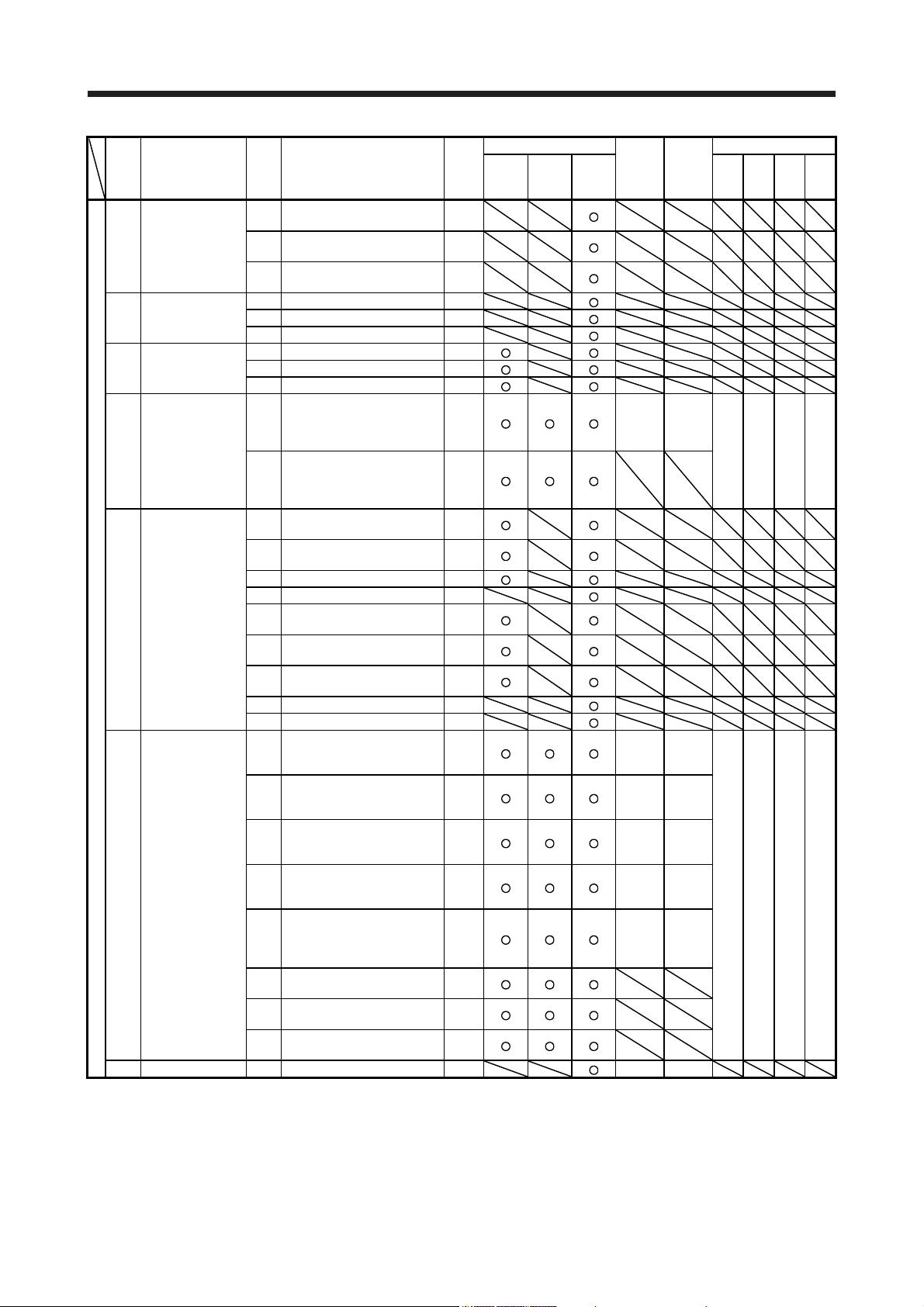
1.3 Warning list
Stop
No. Name
Home position
return incomplete
90 90.2
Warning
90.5 Z-phase unpassed
91
92
92.3 Battery degradation
93
95.1 STO1 off detection DB Common All axes
95.2 STO2 off detection DB Common All axes
95 STO warning
95.4
95.5
96.1
96
96.3
96.4
97
97.2 Next station position warning
98
98.2
99.1 Forward rotation stroke end off
99 Stroke limit warning
99.4 Upper stroke limit off (Note 7)
99.5 Lower stroke limit off (Note 7)
9A
9A.2 Optional unit BCD input data error
9B
9B.3 Excess droop pulse 2 warning
9B.4
9C Converter error 9C.1 Converter unit error
9D.1
9D
9D.3
9D.4
warning
Servo amplifier
overheat warning
(Note 1)
Battery cable
disconnection
warning
ABS data transfer
warning
Home position
setting warning
Positioning
specification
warning
Software limit
warning
Optional unit input
data error warning
Error excessive
warning
CC-Link IE warning
1
Detail
No.
90.1 Home position return incomplete
Home position return abnormal
termination
Main circuit device overheat
91.1
warning
Encoder battery cable
92.1
disconnection warning
ABS data transfer requirement
93.1
warning during magnetic pole
detection
STO warning 1 (safety observation
95.3
function)
STO warning 2 (safety observation
function)
STO warning 3 (safety observation
function)
In-position warning at home
positioning
Command input warning at home
96.2
positioning
Servo off warning at home
positioning
Home positioning warning during
magnetic pole detection
Program operation disabled
97.1
warning
Forward rotation-side software
98.1
stroke limit reached
Reverse rotation-side software
stroke limit reached
99.2 Reverse rotation stroke end off
9A.1 Optional unit input data sign error
9B.1 Excess droop pulse 1 warning
Error excessive warning during 0
torque limit
Station number switch change
warning
9D.2 Master station setting warning
Overlapping station number
warning
Mismatched station number
warning
Detail name
Process-
method
(Note 2,
system
3)
(Note 5)
Common
Each
Each
DB
DB
DB
Each
Each
(Note
4, 7)
(Note
4, 7)
Each
Each
Each
Each
Each
Stop
ing
system
(Note 5)
axis
axis
axis
axis
axis
axis
axis
axis
axis
1 - 13
1. TROUBLESHOOTING FOR SERVO AMPLIFIER (DRIVE UNIT)
Stop
No. Name
CC-Link IE warning
9E
Warning
9F Battery warning
9F.2 Battery degradation warning
E0
E1.1
E1.2
E1.3
E1 Overload warning 1
E1.5
E1.6
E1.7
E1.8
E2
E3.1
E3
E3.4
E3.5
E4 Parameter warning E4.1
E5
E5.2 ABSM off during ABS data transfer
E5.3 SON off during ABS data transfer
E6.2
E6
E6.3
Controller forced stop
E7
E8
E8.2 Cooling fan stop Common
E9.2
E9
E9.3
E9.4 Converter unit forced stop DB
EA
EB
EC Overload warning 2 EC.1 Overload warning 2
2
Excessive
regeneration
warning
Servo motor
overheat warning
Absolute position
counter warning
ABS time-out
warning
Servo forced stop
warning
warning
Cooling fan speed
reduction warning
Main circuit off
warning
ABS servo-on
warning
The other axis error
warning
Detail
No.
9E.1 CC-Link IE communication warning
9F.1 Low battery
E0.1 Excessive regeneration warning Common
Thermal overload warning 1 during
operation
Thermal overload warning 2 during
operation
Thermal overload warning 3 during
operation
Thermal overload warning 4 during
E1.4
operation
Thermal overload error 1 during a
stop
Thermal overload error 2 during a
stop
Thermal overload error 3 during a
stop
Thermal overload error 4 during a
stop
E2.1 Servo motor temperature warning
Multi-revolution counter travel
distance excess warning
E3.2 Absolute position counter warning
Absolute positioning counter EEPROM writing frequency warning
Encoder absolute positioning
counter warning
Parameter setting range error
warning
E5.1 Time-out during ABS data transfer
E6.1 Forced stop warning SD Common All axes
SS1 forced stop warning 1 (safety
observation function)
SS1 forced stop warning 2 (safety
observation function)
E7.1 Controller forced stop warning SD Common All axes
Decreased cooling fan speed
E8.1
warning
Servo-on signal on during main
E9.1
circuit off
Bus voltage drop during low speed
operation
Ready-on signal on during main
circuit off
EA.1 ABS servo-on warning
EB.1 The other axis error warning DB
Detail name
Process-
method
(Note 2,
system
3)
(Note 5)
Each
Each
Each
Each
Each
Each
Each
Each
Each
Each
Each
Each
Each
Each
SD
SD
Common
DB Common All axes
DB Common All axes
DB Common All axes
Each
Each
Stop
ing
system
(Note 5)
axis
axis
axis
axis
axis
axis
axis
axis
axis
axis
axis
axis
axis
axis
(Note 6)
axis
axis
1 - 14
1. TROUBLESHOOTING FOR SERVO AMPLIFIER (DRIVE UNIT)
A
Stop
No. Name
Output watt excess
ED
Warning
F0 Tough drive warning
F2
F2.2
F3
F4.6
F4 Positioning warning
F4.7
F4.9
F5
F5.2 Cam data - Area miswriting warning
F5.3 Cam data checksum error
F6.1
F6
F6.3 Cam unregistered error
F6.4
F6.5 Cam No. external error
F6.6 Cam control inactive
F7
F7.2 Friction failure prediction warning
F7.3
Note 1. After resolving the source of trouble, cool the equipment for approximately 30 minutes.
warning
Drive recorder -
Miswriting warning
Oscillation detection
warning
Simple cam
function - Cam data
miswriting warning
Simple cam
function - Cam
control warning
Machine diagnosis
warning
Detail
No.
ED.1 Output watt excess warning
Instantaneous power failure tough
F0.1
drive warning
F0.3 Vibration tough drive warning
Drive recorder - Area writing time-
F2.1
out warning
Drive recorder - Data miswriting
warning
F3.1 Oscillation detection warning
Target position setting range error
F4.4
warning
Acceleration time constant setting
range error warning
Deceleration time constant setting
range error warning
Home position return type error
warning
Cam data - Area writing time-out
F5.1
warning
Cam axis one cycle current value
restoration failed
Cam axis feed current value
F6.2
restoration failed
Cam control data setting range
error
F7.1 Vibration failure prediction warning
Total travel distance failure
prediction warning
Detail name
Process-
method
(Note 2,
system
3)
(Note 5)
Each
Each
Each
Common
Common
Each
Each
Each
Each
2. The following shows two stop methods of DB and SD.
DB: Stops with dynamic brake. (Coasts for the servo amplifier without dynamic brake.)
Coasts for MR-J4-03A6(-RJ) and MR-J4W2-0303B6.
SD: Forced stop deceleration
3. This is applicable when [Pr. PA04] is set to the initial value. The stop system of SD can be changed to DB
using [Pr. PA04].
4. For MR-J4-_A_ servo amplifier, quick stop or slow stop can be selected using [Pr. PD30].
5. The processing and stop systems are applicable only for the multi-axis servo amplifiers (MR-J4W_-_B_).
Refer to section 1.1 for details.
6.
s the initial value, it is applicable only for [AL. 24] and [AL. 32]. All-axis stop can be selected using [Pr.
PF02].
7. For MR-J4-_GF_ servo amplifier, quick stop or slow stop can be selected using [Pr. PD12]. (I/O mode
only)
ing
axis
axis
axis
axis
axis
axis
axis
Stop
system
(Note 5)
1 - 15
1. TROUBLESHOOTING FOR SERVO AMPLIFIER (DRIVE UNIT)
1.4 Remedies for alarms
When any alarm has occurred, eliminate its cause, ensure safety, and deactivate
the alarm before restarting operation. Otherwise, it may cause injury.
CAUTION
If [AL. 25 Absolute position erased] occurs, always make home position setting
again. Otherwise, it may cause an unexpected operation.
As soon as an alarm occurs, make the Servo-off status and interrupt the main
circuit power.
POINT
When any of the following alarms has occurred, do not cycle the power
repeatedly to restart. Doing so will cause a malfunction of the servo amplifier
and servo motor. Remove its cause and allow about 30 minutes for cooling
before resuming the operation.
[AL. 30 Regenerative error] [AL. 45 Main circuit device overheat]
[AL. 46 Servo motor overheat] [AL. 50 Overload 1]
[AL. 51 Overload 2]
[AL. 37 Parameter error] is not recorded in the alarm history.
Remove the cause of the alarm in accordance with this section. Use MR Configurator2 to refer to the cause
of alarm occurrence.
1 - 16
1. TROUBLESHOOTING FOR SERVO AMPLIFIER (DRIVE UNIT)
Alarm No.: 10 Name: Undervoltage
Alarm content
Detail
No.
10.1 Voltage drop in
Detail name Cause Check method Check result Action Target
the control
It has no failure. Check (2).
circuit power
(2) The voltage of the
The voltage is
(3) The power was cycled
It has no problem. Check (4).
(4) An instantaneous
It has no problem. Check (5).
(5) When a power
The voltage of the control circuit power supply has dropped.
The voltage of the main circuit power supply has dropped.
(1) The control circuit
power supply
connection is incorrect.
control circuit power
supply is low.
before the internal
control circuit power
supply stopped.
power failure has
occurred for longer
time than the specified
time.
The time will be 60 ms
when [Pr. PA20] is "_ 0
_ _".
The time will be the
value set in [Pr. PF25]
when [Pr. PA20] is "_ 1
_ _".
The time will be 60 ms
when [Pr. PX25] is "_ 0
_ _" and the J3
extension function is
used. The time will be
the value set in [Pr.
PX28] when [Pr. PX25]
is "_ 1 _ _".
An instantaneous power
failure of 15 ms or
longer has occurred on
MR-J4-03A6(-RJ) or
MR-J4W2-0303B6.
regeneration converter
is used, the voltage of
the control circuit power
supply is distorted.
Check the connection
of the control circuit
power supply.
Check if the voltage of
the control circuit
power supply is lower
than prescribed value.
200 V class: 160 V
AC
400 V class: 280 V
AC
100 V class: 83 V AC
24 V DC input: 17 V
DC
Check the power-on
method if it has a
problem.
Check if the power
has a problem.
Check if the power
has a problem.
When power supply
impedance is high,
power supply voltage
will be distorted due to
current at power
regeneration, and it
may be recognized as
undervoltage.
It has a failure. Connect it correctly. [A]
The voltage is the
prescribed value or
lower.
higher than the
prescribed value.
It has a problem. Cycle the power
It has a problem. Review the power.
It has a problem. Review the setting
Review the voltage
of the control circuit
power supply.
Check (3).
after the sevensegment LED of the
servo amplifier is
turned off.
of "[AL. 10
Undervoltage]
detection method
selection" with the
following
parameters.
[A]: [Pr. PC27]
[B] [WB] [RJ010]
[GF]: [Pr. PC20]
Review the power.
[B]
[WB]
[RJ010]
[GF]
1 - 17
1. TROUBLESHOOTING FOR SERVO AMPLIFIER (DRIVE UNIT)
Alarm No.: 10 Name: Undervoltage
Alarm content
Detail
No.
10.2 Voltage drop in
Detail name Cause Check method Check result Action Target
the main circuit
power
It is connected. Check (2).
(2) The wiring between P3
It is connected. Check (3).
(3) For the drive unit, the
It has no failure. Check (4).
(4) For the drive unit, the
It has no failure. Check (5).
(5) The voltage of the main
The voltage is
(6) The alarm has
The voltage is equal
The voltage of the control circuit power supply has dropped.
The voltage of the main circuit power supply has dropped.
(1) The main circuit power
supply wiring was
disconnected.
For the drive unit, the
main circuit power
supply wiring of the
converter unit was
disconnected.
and P4 was
disconnected.
For the drive unit, the
wiring between P1 and
P2 of the converter unit
was disconnected.
magnetic contactor
control connector of the
converter unit was
disconnected.
bus bar between the
converter unit and drive
unit was disconnected.
circuit power supply is
low.
occurred during
acceleration.
Check the main circuit
power supply wiring.
Check the main circuit
power supply wiring of
the converter unit.
Check the wiring
between P3 and P4.
Check the wiring
between P1 and P2 of
the converter unit.
Check the magnetic
contactor control
connector of the
converter unit.
Check the bus bar
between the converter
unit and drive unit.
Check if the voltage of
the main circuit power
supply is the
prescribed value or
lower.
200 V class: 160 V
AC
400 V class: 280 V
AC
100 V class: 83 V AC
48 V DC setting: 35 V
DC
24 V DC setting: 15 V
DC
Check if the bus
voltage during
acceleration is lower
than the prescribed
value.
200 V class: 200 V
DC
400 V class: 380 V
DC
100 V class: 158 V
DC
48 V DC setting: 35 V
DC
24 V DC setting: 15 V
DC
It is disconnected. Connect it correctly. [A]
It is disconnected. Connect it correctly.
It is disconnected. Connect it correctly.
It is disconnected. Connect it correctly.
The voltage is the
prescribed value or
lower.
higher than the
prescribed value.
The voltage is lower
than the prescribed
value.
to or higher than the
prescribed value.
Increase the voltage
of the main circuit
power supply.
Check (6).
Increase the
acceleration time
constant. Or
increase the power
supply capacity.
Check (7).
[B]
[WB]
[RJ010]
[GF]
1 - 18
1. TROUBLESHOOTING FOR SERVO AMPLIFIER (DRIVE UNIT)
Alarm No.: 10 Name: Undervoltage
Alarm content
Detail
No.
10.2 Voltage drop in
Detail name Cause Check method Check result Action Target
the main circuit
power
(8) For the drive unit, the
The voltage of the control circuit power supply has dropped.
The voltage of the main circuit power supply has dropped.
(7) The servo amplifier is
malfunctioning.
converter unit is
malfunctioning.
Check the bus
voltage value.
Replace the converter
unit, and then check
the repeatability.
The bus voltage is
less than the
prescribed value
although the voltage
of the main circuit
power supply is
within specifications.
200 V class: 200 V
DC
400 V class: 380 V
DC
100 V class: 158 V
DC
48 V DC setting:
24 V DC setting:
It is not repeatable. Replace the
Replace the servo
amplifier.
35 V DC
15 V DC
converter unit.
[A]
[B]
[WB]
[RJ010]
1 - 19
1. TROUBLESHOOTING FOR SERVO AMPLIFIER (DRIVE UNIT)
Alarm No.: 11 Name: Switch setting error
The setting of the axis selection rotary switch or auxiliary axis number setting switch is incorrect.
Alarm content
Detail
No.
11.1 Axis number
11.2 Disabling
The setting is other
Detail name Cause Check method Check result Action Target
setting error
Both of the auxiliary
Station number
setting error
The station number
control axis
setting error
Alarm No.: 12 Name: Memory error 1 (RAM)
Alarm content A part (RAM) in the servo amplifier is failure.
Detail
No.
12.1 RAM error 1 (1) A part in the servo
12.2 RAM error 2 Check it with the check method for [AL. 12.1].
12.3 RAM error 3
12.4 RAM error 4
12.5 RAM error 5
12.6 RAM error 6
Detail name Cause Check method Check result Action Target
It is not repeatable. Check (2).
(2) Something near the
The setting of the disabling control axis switch is incorrect.
The setting of the station number selection rotary switch is incorrect.
(1) The setting of the axis
No. is incorrect.
(2) The station number is
set to a value other
than "1" to "120" with
the station number
selection rotary switch.
(1) The setting of the
disabling control axis
switch is incorrect.
amplifier is failure.
device caused it.
Check the settings of
the auxiliary axis
number setting
switches (SW25/SW2-6) and axis
selection rotary switch
(SW1).
Check the settings of
the station number
selection rotary
switches (SW2/SW3).
Check the setting of
the disabling control
axis switch.
Disconnect the cables
except for the control
circuit power supply,
and then check the
repeatability.
Check the power
supply for noise.
When both of the
auxiliary axis
number setting
switches are on,
check the axis
selection rotary
switch if "F" is
selected for MRJ4W2, ("E" or "F" is
selected for MRJ4W3).
axis number setting
switches are off.
The setting of the
station number
selection rotary
switch is set to "0"
or "121" or more.
is set to a value from
"1" to "120" with the
station number
selection rotary
switch.
Check if the setting
is as follows.
1) Only A-axis is
disabled.
2) Only B-axis is
disabled.
3) A-axis and B-axis
are disabled.
4) A-axis and C-axis
are disabled.
5) All axes are
disabled.
than above.
It is repeatable. Replace the servo
It has a failure. Take
Set the axis No.
correctly.
Replace the servo
amplifier.
Set the station
number correctly.
Replace the servo
amplifier.
Set it correctly. [WB]
Replace the servo
amplifier.
amplifier.
countermeasures
against its cause.
[WB]
[GF]
[A]
[B]
[WB]
[RJ010]
[GF]
1 - 20
1. TROUBLESHOOTING FOR SERVO AMPLIFIER (DRIVE UNIT)
Alarm No.: 13 Name: Clock error
A part in the servo amplifier is failure.
Alarm content
Detail
No.
13.1 Clock error 1 (1) The MR-J3-T10 came
13.2 Clock error 2 Check it with the check method for [AL. 13.1].
Detail name Cause Check method Check result Action Target
It did not occur. Check (2).
(2) A part in the servo
It is not repeatable. Check (3).
(3) A clock error
It does not occur. Check (4).
(4) The servo amplifier of
It is not
(5) Something near the
Alarm No.: 14 Name: Control process error
Alarm content
Detail
No.
14.1 Control
Detail name Cause Check method Check result Action Target
process error 1
It did not occur. Check (2).
(2) The parameter setting
It is correct. Check (3).
(3) Something near the
It has no failure. Check (4).
(4) The servo amplifier is
A clock error transmitted from the controller occurred.
[RJ010]: MR-J3-T10 came off.
Check if [AL. 74
off during the CC-Link
IE communication.
amplifier is failure.
transmitted from the
controller occurred.
the next axis is
malfunctioning.
device caused it.
The process did not complete within the specified time.
[RJ010]: MR-J3-T10 came off.
[GF]: A part (communication IC) in the servo amplifier is failure.
(1) The MR-J3-T10 came
off during the CC-Link
IE communication.
is incorrect.
device caused it.
malfunctioning.
Option card error 1]
occurred with alarm
history.
Disconnect the cables
except for the control
circuit power supply,
and then check the
repeatability.
Check if the alarm
occurs when you
connect the amplifier
to the controller.
Check if the servo
amplifier of the next
axis is malfunctioning.
Check the power
supply for noise.
Check if the connector
is shorted.
Check if [AL. 74
Option card error 1]
occurred with alarm
history.
Check if the
parameter setting is
incorrect.
Check the power
supply for noise.
Check if the connector
is shorted.
Replace the servo
amplifier, and then
check the
repeatability.
It is occurring. Check it with the
It is repeatable. Replace the servo
It occurs. Replace the
It is malfunctioning. Replace the servo
malfunctioning.
It has a failure. Take
It is occurring. Check it with the
It is incorrect. Set it correctly. [A]
It has a failure. Take
It is not repeatable. Replace the servo
check method for
[AL. 74].
amplifier.
controller.
amplifier of the next
axis.
Check (5).
countermeasures
against its cause.
check method for
[AL. 74].
countermeasures
against its cause.
amplifier.
[RJ010]
[A]
[B]
[WB]
[RJ010]
[GF]
[B]
[WB]
[A]
[B]
[WB]
[RJ010]
[GF]
[RJ010]
[B]
[WB]
[RJ010]
[GF]
1 - 21
1. TROUBLESHOOTING FOR SERVO AMPLIFIER (DRIVE UNIT)
Alarm No.: 14 Name: Control process error
The process did not complete within the specified time.
Alarm content
Detail
No.
14.2 Control
14.3 Control
14.4 Control
14.5 Control
14.6 Control
14.7 Control
14.8 Control
14.9 Control
14.A Control
14.B Control
Detail name Cause Check method Check result Action Target
process error 2
It did not occur. Check (2).
(2) A synchronous signal
It is not repeatable. Check (3).
(3) Adaptive tuning mode
It has not been
(4) The parameter setting
It is correct. Check (5).
(5) Something near the
It has no failure. Check (6).
(6) The servo amplifier is
process error 3
process error 4
process error 5
process error 6
process error 7
process error 8
process error 9
process error 10
process error 11
[RJ010]: MR-J3-T10 came off.
[GF]: A part (communication IC) in the servo amplifier is failure.
(1) The MR-J3-T10 came
off during the CC-Link
IE communication.
error transmitted from
the controller occurred.
or vibration
suppression control
tuning mode has been
executed for multiple
axes simultaneously.
is incorrect.
device caused it.
malfunctioning.
Check it with the check method for [AL. 14.1].
Check if [AL. 74
Option card error 1]
occurred with alarm
history.
Replace the
controller, and then
check the
repeatability.
Check the setting of
[Pr. PB01] or [Pr.
PB02].
With the J3 extension
function, Check the
setting of [Pr. PB01],
[Pr. PB02], or [Pr.
PX03].
Check if the
parameter setting is
incorrect.
Check the power
supply for noise.
Check if the
connector is shorted.
Replace the servo
amplifier, and then
check the
repeatability.
It is occurring. Check it with the
check method for
[AL. 74].
It is repeatable. Replace the servo
amplifier.
It has been
executed for
multiple axes
simultaneously.
executed for
multiple axes
simultaneously.
It is incorrect. Set it correctly. [A]
It has a failure. Take
It is not repeatable. Replace the servo
Execute it for each
axis.
Check (4).
countermeasures
against its cause.
amplifier.
[RJ010]
[B]
[WB]
[WB]
[B]
[WB]
[RJ010]
[GF]
1 - 22
1. TROUBLESHOOTING FOR SERVO AMPLIFIER (DRIVE UNIT)
Alarm No.: 15 Name: Memory error 2 (EEP-ROM)
Alarm content
Detail
No.
15.1 EEP-ROM error
15.2 EEP-ROM error
15.4 Home position
Detail name Cause Check method Check result Action Target
at power on
It is not repeatable. Check (2).
(2) Something near the
It has no failure. Check (3).
(3) The number of write
during operation
It did not occur. Check (2).
(2) EEP-ROM is
It does not occur. Check (3).
(3) A write error occurred
It takes less than an
(4) Something near the
information read
error
It is not repeatable. Check (2).
(2) Multiple rotation data
It has no failure. Check (3).
(3) Something near the
It has no failure. Check (4).
(4) The number of write
A part (EEP-ROM) in the servo amplifier is failure.
[RJ010]: MR-J3-T10 came off.
(1) EEP-ROM is
malfunctioning at power
on.
device caused it.
times exceeded
100,000.
(1) The MR-J3-T10 came
off during the CC-Link
IE communication.
malfunctioning during
normal operation.
while adjustment results
were processed.
device caused it.
(1) EEP-ROM is
malfunctioning at power
on.
saved as a home
position and read from
EEP-ROM were failure.
device caused it.
times exceeded
100,000.
Disconnect the cables
except for the control
circuit power supply,
and then check the
repeatability.
Check the power
supply for noise.
Check if the connector
is shorted.
Check if parameters,
point tables, or
programs are changed
very frequently.
Check if [AL. 74
Option card error 1]
occurred with alarm
history.
Check if the error
occurs when you
change parameters
during normal
operation.
Check if the alarm
occurs after an hour
from power on.
Check the power
supply for noise.
Check if the connector
is shorted.
Disconnect the cables
except for the control
circuit power supply,
and then check the
repeatability.
Check if the home
position was set
correctly.
Check the power
supply for noise.
Check if the connector
is shorted.
Check if parameters
has been used very
frequently.
It is repeatable. Replace the servo
amplifier.
It has a failure. Take
countermeasures
against its cause.
It was changed. Replace the servo
amplifier. Change
the process to use
parameters, point
tables, and programs
less frequently after
replacement.
It is occurring. Check it with the
check method for
[AL. 74].
It occurs. Replace the servo
amplifier.
It takes an hour or
more.
hour.
It has a failure. Take
It is repeatable. Replace the servo
It has a failure. Make home position
It has a failure. Take
It was changed. Replace the servo
Replace the servo
amplifier.
Check (4).
countermeasures
against its cause.
amplifier.
setting again.
countermeasures
against its cause.
amplifier. Change
the process to use
parameters less
frequently after
replacement.
[A]
[B]
[WB]
[RJ010]
[GF]
[RJ010]
[A]
[B]
[WB]
[RJ010]
[GF]
[A]
[GF]
1 - 23

1. TROUBLESHOOTING FOR SERVO AMPLIFIER (DRIVE UNIT)
Alarm No.: 16 Name: Encoder initial communication error 1
Alarm content An error occurred in the communication between an encoder and servo amplifier.
Detail
No.
16.1 Encoder initial
16.2 Encoder initial
Detail name Cause Check method Check result Action Target
(1) An encoder cable is
communication
- Receive data
It has no failure. Check (2).
error 1
(2) When you use a linear
The servo amplifier
(3) When you use a linear
The wiring is
(4) The servo amplifier is
It is repeatable. Check (5).
(5) An encoder is
It is repeatable. Check (6).
(6) Something near the
communication
- Receive data
error 2
malfunctioning.
servo motor with an
A/B/Z-phase differential
output linear encoder,
the servo amplifier is
not compatible with the
linear encoder.
servo motor with an
A/B/Z-phase differential
output linear encoder,
the connection with the
linear encoder is
incorrect.
malfunctioning.
malfunctioning.
device caused it.
Check it with the check method for [AL. 16.1].
Check if the encoder
cable is disconnected
or shorted.
Check if the servo
amplifier (MR-J4-_-RJ)
is compatible with the
A/B/Z-phase
differential output
linear encoder.
Check if the wiring of
the linear encoder is
correct. (Check if it is
wired to PSEL.)
Replace the servo
amplifier, and then
check the
repeatability.
Replace the servo
motor or linear
encoder, and then
check the
repeatability.
Check the noise,
ambient temperature,
vibration, etc.
It has a failure. Replace or repair
the cable.
The servo amplifier
is not compatible
with it.
is compatible with it.
The wiring is
incorrect.
correct.
It is not repeatable. Replace the servo
It is not repeatable. Replace the servo
It has a failure. Take
Use a servo
amplifier which is
compatible with it.
Check (3).
Wire it correctly.
Check (4).
amplifier.
motor.
countermeasures
against its cause.
[A]
[B]
[WB]
[RJ010]
[GF]
[A]
[B]
[GF]
[A]
[B]
[WB]
[RJ010]
[GF]
1 - 24

1. TROUBLESHOOTING FOR SERVO AMPLIFIER (DRIVE UNIT)
Alarm No.: 16 Name: Encoder initial communication error 1
Alarm content An error occurred in the communication between an encoder and servo amplifier.
Detail
No.
16.3 Encoder initial
Detail name Cause Check method Check result Action Target
(1) An axis not used is not
communication
- Receive data
It is set as disabled-
error 3
(2) An encoder cable was
It is connected. Check (3).
(3) The parameter setting
The setting is
(4) An encoder cable is
It has no failure. Check (5).
set as disabled-axis.
disconnected.
of communication
method is incorrect.
[A]: [Pr. PC22]
[B] [WB] [RJ010] [GF]:
[Pr. PC04]
malfunctioning.
Check the setting of
the disabling control
axis switches (SW2-
2/SW2-3/SW2-4).
Check if the encoder
cable is connected
correctly.
Check the parameter
setting.
Check if the encoder
cable is disconnected
or shorted.
It is not set as
disabled-axis.
axis.
It is not connected. Connect it correctly. [A]
The setting is
incorrect.
correct.
It has a failure. Replace or repair
Set it as disabledaxis.
Check (2).
Set it correctly.
Check (4).
the cable.
[WB]
[B]
[WB]
[RJ010]
[GF]
(5) When you use a linear
servo motor with an
A/B/Z-phase differential
The wiring is
(6) The voltage of the
It has no failure. Check (7).
(7) The servo amplifier is
It is repeatable. Check (8).
(8) An encoder is
It is repeatable. Check (9).
(9) Something near the
16.5 Encoder initial
communication
- Transmission
data error 1
16.6 Encoder initial
communication
- Transmission
data error 2
16.7 Encoder initial
communication
- Transmission
data error 3
output linear encoder,
the connection with the
linear encoder is
incorrect.
control circuit power
supply has been
unstable.
malfunctioning.
malfunctioning.
device caused it.
Check it with the check method for [AL. 16.1].
Check if the wiring of
the linear encoder is
correct. (Check if it is
wired to PSEL.)
Check the voltage of
the control circuit
power supply.
Replace the servo
amplifier, and then
check the
repeatability.
Replace the servo
motor, and then
check the
repeatability.
Check the noise,
ambient temperature,
vibration, etc.
The wiring is
incorrect.
correct.
An instantaneous
power failure is
occurring at the
control circuit power
supply.
It is not repeatable. Replace the servo
It is not repeatable. Replace the servo
It has a failure. Take
Wire it correctly. [A]
Check (6).
Review the power
and related parts.
amplifier.
motor.
countermeasures
against its cause.
[B]
[GF]
[A]
[B]
[WB]
[RJ010]
[GF]
1 - 25

1. TROUBLESHOOTING FOR SERVO AMPLIFIER (DRIVE UNIT)
Alarm No.: 16 Name: Encoder initial communication error 1
Alarm content An error occurred in the communication between an encoder and servo amplifier.
Detail
No.
16.A Encoder initial
Detail name Cause Check method Check result Action Target
(1) The servo amplifier is
communication Process error 1
It is repeatable. Check (2).
(2) An encoder is
It is repeatable. Check (3).
malfunctioning.
malfunctioning.
Replace the servo
amplifier, and then
check the
repeatability.
Replace the servo
motor, and then check
the repeatability.
It is not repeatable. Replace the servo
amplifier.
It is not repeatable. Replace the servo
motor.
[A]
[B]
[WB]
[RJ010]
[GF]
(3) Something near the
device caused it.
16.B Encoder initial
communication Process error 2
16.C Encoder initial
communication Process error 3
16.D Encoder initial
communication Process error 4
16.E Encoder initial
communication Process error 5
16.F Encoder initial
communication Process error 6
Check it with the check method for [AL. 16.A].
Check the noise,
ambient temperature,
vibration, etc.
It has a failure. Take
countermeasures
against its cause.
Alarm No.: 17 Name: Board error
Alarm content A part in the servo amplifier is malfunctioning.
Detail
No.
17.1 Board error 1 (1) A current detection
17.3 Board error 2 Check it with the check method for [AL. 17.1].
17.4 Board error 3 (1) The servo amplifier
17.5 Board error 4 (1) The setting value of the
Detail name Cause Check method Check result Action Target
Check if the alarm
circuit is
It does not occur. Check (2).
(2) Something near the
It is not repeatable. Check (2).
(2) Something near the
It is not repeatable. Check (2).
(2) Something near the
malfunctioning.
device caused it.
recognition signal was
not read properly.
device caused it.
axis selection rotary
switch (SW1) was not
read properly.
device caused it.
occurs during the
servo-on status.
Check the noise,
ambient temperature,
etc.
Disconnect the cables
except for the control
circuit power supply,
and then check the
repeatability.
Check the noise,
ambient temperature,
etc.
Disconnect the cables
except for the control
circuit power supply,
and then check the
repeatability.
Check the noise,
ambient temperature,
etc.
It occurs. Replace the servo
amplifier.
It has a failure. Take
countermeasures
against its cause.
It is repeatable. Replace the servo
amplifier.
It has a failure. Take
countermeasures
against its cause.
It is repeatable. Replace the servo
amplifier.
It has a failure. Take
countermeasures
against its cause.
[A]
[B]
[WB]
[RJ010]
[GF]
[B]
[WB]
1 - 26

1. TROUBLESHOOTING FOR SERVO AMPLIFIER (DRIVE UNIT)
Alarm No.: 17 Name: Board error
Alarm content A part in the servo amplifier is malfunctioning.
Detail
No.
17.6 Board error 5 (1) The setting value of the
17.7 Board error 7 Check it with the check method for [AL. 17.4].
17.8 Board error 6 (1) Inrush current
17.9 Board error 8 (1) Something near the
Alarm No.: 19 Name: Memory error 3 (Flash-ROM)
Detail
No.
19.1 Flash-ROM
19.2 Flash-ROM
19.3 Flash-ROM
Detail name Cause Check method Check result Action Target
Disconnect the cables
control axis setting
It is not repeatable. Check (2).
(2) Something near the
It has no failure. Check (2).
(2) The servo amplifier is
Alarm content A part (Flash-ROM) in the servo amplifier is failure.
Detail name Cause Check method Check result Action Target
error 1
It is not repeatable. Check (2).
(2) Something near the
error 2
error 3
switch (SW2) was not
read properly.
device caused it.
suppressor circuit is
malfunctioning.
device caused it.
malfunctioning.
(1) The Flash-ROM is
malfunctioning.
device caused it.
Check it with the check method for [AL. 19.1].
except for the control
circuit power supply,
and then check the
repeatability.
Check the noise,
ambient temperature,
etc.
Replace the servo
amplifier, and then
check the
repeatability.
Check the noise,
ambient temperature,
etc.
Replace the servo
amplifier, and then
check the
repeatability.
Disconnect the cables
except for the control
circuit power supply,
and then check the
repeatability.
Check the noise,
ambient temperature,
etc.
It is repeatable. Replace the servo
amplifier.
It has a failure. Take
countermeasures
against its cause.
It is not repeatable. Replace the servo
amplifier.
It has a failure. Take
countermeasures
against its cause.
It is not repeatable. Replace the servo
amplifier.
It is repeatable. Replace the servo
amplifier.
It has a failure. Take
countermeasures
against its cause.
[B]
[WB]
[B]
[WB]
[GF]
[A]
[B]
[WB]
[RJ010]
[GF]
1 - 27

1. TROUBLESHOOTING FOR SERVO AMPLIFIER (DRIVE UNIT)
Alarm No.: 1A Name: Servo motor combination error
Alarm content The combination of servo amplifier and servo motor is incorrect.
Detail
No.
1A.1 Servo motor
1A.2 Servo motor
1A.4 Servo motor
Alarm No.: 1B Name: Converter alarm
Detail
No.
1B.1 Converter unit
Detail name Cause Check method Check result Action Target
(1) The servo amplifier and
combination
error 1
The combination is
(2) The setting of [Pr. PA01]
The combination is
(3) [Pr. PA17] and [Pr.
It is set correctly. Check (4).
(4) The software version of
It is C8 or later. Check (5).
(5) An encoder is
control mode
combination
error
(2) When the fully closed
combination
error 2
Alarm content An alarm occurred in the converter unit during the servo-on.
Detail name Cause Check method Check result Action Target
error
It is connected. Check (2).
the servo motor was
connected incorrectly.
is not corresponding to
the connected servo
motor.
PA18] were not set
according to the linear
servo motor to be used.
the servo amplifier
does not support the
TM-RG2M/TM-RU2M
series direct drive
motor.
malfunctioning.
(1) The setting of [Pr. PA01]
is not corresponding to
the connected servo
motor.
loop control mode is
selected, encoders of
the servo motor side
and the machine side
are connected
reversely.
(1) The servo amplifier is
malfunctioning.
(1) The protection
coordination cable is not
correctly connected.
(2) An alarm occurred in
the converter unit
during the servo-on.
Check the model
name of the servo
motor and
corresponding servo
amplifier.
Check the [Pr. PA01]
setting.
Rotary servo motor:
"_ _ 0 _"
Linear servo motor: "_
_ 4 _"
Direct drive motor: "_
_ 6 _"
Check if [Pr. PA17]
and [Pr. PA18] are
set correctly.
Check if the software
version of the servo
amplifier supports the
TM-RG2M/TM-RU2M
series.
Replace the servo
motor, and then
check the
repeatability.
Check the [Pr. PA01]
setting.
Rotary servo motor:
"_ _ 0 _"
Linear servo motor: "_
_ 4 _"
Direct drive motor: "_
_ 6 _"
Check the connection
destination of the
encoder.
Replace the servo
amplifier, and then
check the
repeatability.
Check the protection
coordination cable
connection.
Check the alarm of the converter unit, and take the action following
the remedies for alarms of the converter unit.
The combination is
incorrect.
correct.
The combination is
incorrect.
correct.
It is not set
correctly.
It is C7 or earlier. Replace the servo
It is not repeatable. Replace the servo
The combination is
incorrect.
The connection
destination of the
encoder is incorrect.
It is not repeatable. Replace the servo
It is not connected. Connect it correctly. [A]
Use them in the
correct combination.
Check (2).
Set [Pr. PA01]
correctly.
When using a linear
servo motor, also
check (3).
Check (4).
Set them correctly
according to the
linear servo motor to
be used.
amplifier with a one
whose software
version supports the
TM-RG2M/TMRU2M series.
motor.
Set [Pr. PA01]
correctly.
Connect it correctly.
amplifier.
[A]
[B]
[WB]
[RJ010]
[GF]
[A]
[B]
[WB]
[GF]
[A]
[B]
[WB]
[RJ010]
[GF]
[A]
[B]
[WB]
[GF]
[B]
1 - 28

1. TROUBLESHOOTING FOR SERVO AMPLIFIER (DRIVE UNIT)
Alarm No.: 1E Name: Encoder initial communication error 2
Alarm content An encoder is malfunctioning.
Detail
No.
1E.1 Encoder
1E.2 Load-side
Alarm No.: 1F Name: Encoder initial communication error 3
Detail
No.
1F.1 Incompatible
Detail name Cause Check method Check result Action Target
(1) An encoder is
malfunction
It is repeatable. Check (2).
(2) Something near the
encoder
malfunction
It is repeatable. Check (2).
(2) Something near the
Alarm content The connected encoder is not compatible with the servo amplifier.
Detail name Cause Check method Check result Action Target
encoder
It is compatible with
(2) The software version of
It is compatible. Check (3).
(3) An encoder is
It is repeatable. Replace the servo
malfunctioning.
device caused it.
(1) A load-side encoder is
malfunctioning.
device caused it.
(1) A servo motor or linear
encoder, which is not
compatible with the
servo amplifier, was
connected.
the servo amplifier does
not support the servo
motor or linear encoder.
malfunctioning.
Replace the servo
motor, and then
check the
repeatability.
Check the noise,
ambient temperature,
vibration, etc.
Replace the load-side
encoder, and then
check the
repeatability.
Check the noise,
ambient temperature,
vibration, etc.
Check the model the
servo motor/linear
encoder.
Check if the software
version supports the
servo motor/linear
encoder.
Replace the servo
motor or linear
encoder, and then
check the
repeatability.
It is not repeatable. Replace the servo
motor.
It has a failure. Take
countermeasures
against its cause.
It is not repeatable. Replace the load-
side encoder.
It has a failure. Take
countermeasures
against its cause.
It is not compatible
with the servo
amplifier.
the servo amplifier.
It is not compatible. Replace the servo
It is not repeatable. Replace the servo
Replace it with a
compatible one.
Check (2).
amplifier to one
which software
version supports the
servo motor/linear
encoder.
motor or linear
encoder.
amplifier.
[A]
[B]
[WB]
[RJ010]
[GF]
[A]
[B]
[WB]
[GF]
[A]
[B]
[WB]
[RJ010]
[GF]
1F.2 Incompatible
load-side
encoder
It is compatible with
(2) The software version of
It is compatible. Check (3).
(3) A load-side encoder is
It is repeatable. Replace the servo
(1) A load-side encoder,
which is not compatible
with the servo amplifier,
was connected.
the servo amplifier
does not support the
load-side encoder.
malfunctioning.
Check the model of
the load-side
encoder.
Check if the software
version of the servo
amplifier supports the
load-side encoder.
Replace the load-side
encoder, and then
check the
repeatability.
It is not compatible
with the servo
amplifier.
the servo amplifier.
It is not compatible. Replace the servo
It is not repeatable. Replace the load-
Use a load-side
encoder which is
compatible with the
servo amplifier.
Check (2).
amplifier to one
which software
version supports the
load-side encoder.
side encoder.
amplifier.
1 - 29
[A]
[B]
[WB]
[GF]

1. TROUBLESHOOTING FOR SERVO AMPLIFIER (DRIVE UNIT)
Alarm No.: 20 Name: Encoder normal communication error 1
Alarm content An error occurred in the communication between an encoder and servo amplifier.
Detail
No.
20.1 Encoder
20.2 Encoder
20.3 Encoder
Detail name Cause Check method Check result Action Target
(1) An encoder cable is
normal
communication
- Receive data
error 1
It has no failure. Check (2).
(2) The external conductor
It is connected. Check (3).
(3) The parameter setting
The setting is
(4) The servo amplifier is
It is repeatable. Check (5).
(5) An encoder is
It is repeatable. Check (6).
(6) Something near the
normal
communication
- Receive data
error 2
normal
communication
- Receive data
error 3
malfunctioning.
of the encoder cable is
not connected to the
ground plate of the
connector.
of communication
method is incorrect.
[A]: [Pr. PC22]
[B] [WB] [RJ010] [GF]:
[Pr. PC04]
malfunctioning.
malfunctioning.
device caused it.
Check it with the check method for [AL. 20.1].
Check if the encoder
cable is disconnected
or shorted. When you
use an A/B/Z-phase
differential output
linear encoder, check
the wiring of the linear
encoder.
Check if it is
connected.
Check the parameter
setting.
Replace the servo
amplifier, and then
check the
repeatability.
Replace the servo
motor or linear
encoder, and then
check the
repeatability.
Check the noise,
ambient temperature,
vibration, etc.
It has a failure. Repair or replace
the cable.
It is not connected. Connect it correctly.
The setting is
incorrect.
correct.
It is not repeatable. Replace the servo
It is not repeatable. Replace the servo
It has a failure. Take
Set it correctly.
Check (4).
amplifier.
motor or linear
encoder.
countermeasures
against its cause.
[A]
[B]
[WB]
[RJ010]
[GF]
1 - 30

1. TROUBLESHOOTING FOR SERVO AMPLIFIER (DRIVE UNIT)
Alarm No.: 20 Name: Encoder normal communication error 1
Alarm content An error occurred in the communication between an encoder and servo amplifier.
Detail
No.
20.5 Encoder
20.6 Encoder
20.7 Encoder
Detail name Cause Check method Check result Action Target
(1) When you use an
normal
communication
- Transmission
It is not
data error 1
(2) An encoder cable is
(3) The external conductor
(4) When you use an
(5) The servo amplifier is
(6) An encoder is
(7) Something near the
normal
communication
- Transmission
It is not
data error 2
(2) An encoder cable is
(3) The external conductor
(4) When you use an
(5) The servo amplifier is
(6) An encoder is
(7) Something near the
normal
communication
- Transmission
data error 3
A/B/Z-phase differential
output linear encoder,
the wiring of the linear
encoder is incorrect.
malfunctioning.
of the encoder cable is
not connected to the
ground plate of the
connector.
A/B/Z-phase differential
output linear encoder,
the parameter setting is
incorrect.
malfunctioning.
malfunctioning.
device caused it.
(1) When you use an
A/B/Z-phase differential
output linear encoder,
the wiring of the linear
encoder is incorrect.
malfunctioning.
of the encoder cable is
not connected to the
ground plate of the
connector.
A/B/Z-phase differential
output linear encoder,
the parameter setting is
incorrect.
malfunctioning.
malfunctioning.
device caused it.
Check it with the check method for [AL. 20.1].
Check if the A/Bphase pulse signals
(PA, PAR, PB, and
PBR) of the encoder
cable are
disconnected or
shorted.
Check it with the check method for [AL. 20.1]. [A]
Check if the Z-phase
pulse signals
(PZ/PZR) of the
encoder cable are
disconnected or
shorted.
Check it with the check method for [AL. 20.1]. [A]
It is disconnected or
shorted.
disconnected or
shorted.
It is disconnected or
shorted.
disconnected or
shorted.
Repair the encoder
cable.
Check (2).
Repair the encoder
cable.
Check (2).
[A]
[B]
[GF]
[B]
[WB]
[RJ010]
[GF]
[A]
[B]
[GF]
[B]
[WB]
[RJ010]
[GF]
1 - 31

1. TROUBLESHOOTING FOR SERVO AMPLIFIER (DRIVE UNIT)
Alarm No.: 20 Name: Encoder normal communication error 1
Alarm content An error occurred in the communication between an encoder and servo amplifier.
Detail
No.
20.9 Encoder
20.A Encoder
Alarm No.: 21 Name: Encoder normal communication error 2
Detail
No.
21.1 Encoder data
21.2 Encoder data
21.3 Encoder data
21.4 Encoder non-
Detail name Cause Check method Check result Action Target
Check it with the check method for [AL. 20.1].
normal
communication
- Receive data
error 4
normal
communication
- Receive data
error 5
Alarm content The encoder detected an error signal.
Detail name Cause Check method Check result Action Target
(1) The encoder detected
error 1
It is repeatable. Check (2).
(2) The external conductor
It is connected. Check (3).
(3) An encoder is
It is repeatable. Check (4).
(4) Something near the
update error
It is repeatable. Check (2).
(2) The external conductor
It is connected. Check (3).
(3) Something near the
waveform error
signal error
It has no failure. Check (2).
(2) The external conductor
It is connected. Check (3).
(3) Something near the
a high speed/
acceleration rate due to
an oscillation or other
factors.
of the encoder cable is
not connected to the
ground plate of the
connector.
malfunctioning.
device caused it.
(1) An encoder is
malfunctioning.
of the encoder cable is
not connected to the
ground plate of the
connector.
device caused it.
Check it with the check method for [AL. 21.2].
(1) A signal of the encoder
has not been inputted.
of the encoder cable is
not connected to the
ground plate of the
connector.
device caused it.
Decrease the loop
gain, and then check
the repeatability.
Check if it is
connected.
Replace the servo
motor, and then
check the
repeatability.
Check the noise,
ambient temperature,
vibration, etc.
Replace the servo
motor, and then check
the repeatability.
Check if it is
connected.
Check the noise,
ambient temperature,
etc.
Check if the encoder
cable is wired
correctly.
Check if it is
connected.
Check the noise,
ambient temperature,
etc.
It is not repeatable. Use the encoder
with low loop gain.
It is not connected. Connect it correctly.
It is not repeatable. Replace the servo
motor.
It has a failure. Take
countermeasures
against its cause.
It is not repeatable. Replace the servo
motor.
It is not connected. Connect it correctly.
It has a failure. Take
countermeasures
against its cause.
It has a failure. Review the wiring. [A]
It is not connected. Connect it correctly.
It has a failure. Take
countermeasures
against its cause.
[A]
[B]
[WB]
[RJ010]
[GF]
[A]
[B]
[WB]
[RJ010]
[GF]
[B]
[WB]
[GF]
1 - 32

1. TROUBLESHOOTING FOR SERVO AMPLIFIER (DRIVE UNIT)
Alarm No.: 21 Name: Encoder normal communication error 2
Alarm content The encoder detected an error signal.
Detail
No.
21.5 Encoder
21.6 Encoder
21.9 Encoder data
Alarm No.: 24 Name: Main circuit error
Detail
No.
24.1 Ground fault
Detail name Cause Check method Check result Action Target
Check it with the check method for [AL. 21.2].
hardware error
1
hardware error
2
Check it with the check method for [AL. 21.1].
error 2
A ground fault occurred on the servo motor power lines.
Alarm content
Detail name Cause Check method Check result Action Target
detected by
hardware
It does not occur. Check (2).
detection circuit
(2) A ground fault or short
It is not shorted. Check (3).
(3) A ground fault occurred
It is not shorted. Check (4).
(4) The main circuit power
They are not in
(5) Something near the
A ground fault occurred at the servo motor.
Power supply voltage for inverter circuit control is low. (Only for MR-J4W2-0303B6)
(1) The servo amplifier is
malfunctioning.
occurred at the servo
motor power cable.
at the servo motor.
supply cable and servo
motor power cable
were shorted.
device caused it.
Disconnect the servo
motor power cables
(U/V/W) and check if
the alarm occurs.
Check if only the
servo motor power
cable is shorted.
Disconnect the servo
motor power cables
on motor side, and
check insulation of
the motor (between
U/V/W/
Shut off the power,
and check if the main
circuit power supply
cable and servo
motor power cable
are in contact.
Check the noise,
ambient temperature,
etc.
).
It occurs. Replace the servo
amplifier.
It is shorted. Replace the servo
motor power cable.
It is shorted. Replace the servo
motor.
They are in contact. Correct the wiring.
Check (5).
contact.
It has a failure. Take
countermeasures
against its cause.
[A]
[B]
[WB]
[RJ010]
[GF]
1 - 33

1. TROUBLESHOOTING FOR SERVO AMPLIFIER (DRIVE UNIT)
Alarm No.: 24 Name: Main circuit error
A ground fault occurred on the servo motor power lines.
Alarm content
Detail
No.
24.2 Ground fault
Detail name Cause Check method Check result Action Target
detected by
software
detection
function
The control circuit
(2) The servo amplifier is
It does not occur. Check (3).
(3) A ground fault or short
It is not shorted. Check (4).
A ground fault occurred at the servo motor.
Power supply voltage for inverter circuit control is low. (Only for MR-J4W2-0303B6)
(1) For MR-J4W2-0303B6,
the servo-on command
was inputted when the
control circuit power
supply voltage was
below 20 V.
malfunctioning.
occurred at the servo
motor power cable.
Check the control
circuit power supply
voltage when the
servo-on command
was inputted.
Disconnect the servo
motor power cable
(U/V/W), and check if
the alarm occurs.
Check if only the
servo motor power
cable is shorted.
The control circuit
power supply
voltage was below
20 V.
power supply voltage
was 20 V or higher.
It occurs. Replace the servo
It is shorted. Replace the servo
Input the servo-on
command after the
control circuit power
supply voltage
reaches 20 V or
higher.
Check (2).
amplifier.
motor power cable.
[WB]
[A]
[B]
[WB]
[RJ010]
[GF]
(4) A ground fault occurred
at the servo motor.
It is not shorted. Check (5).
(5) The main circuit power
supply cable and servo
They are not in
(6) Something near the
motor power cable
were shorted.
device caused it.
Disconnect the servo
motor power cables
on motor side, and
check insulation
between phases
(U/V/W/
Shut off the power,
and check if the main
circuit power supply
cable and servo
motor power cable
are in contact.
Check the noise,
ambient temperature,
etc.
).
It is shorted. Replace the servo
motor.
They are in contact. Correct the wiring.
Check (6).
contact.
It has a failure. Take
countermeasures
against its cause.
1 - 34

1. TROUBLESHOOTING FOR SERVO AMPLIFIER (DRIVE UNIT)
Alarm No.: 25 Name: Absolute position erased
The absolute position data is faulty.
Alarm content
Detail
No.
25.1 Servo motor
Detail name Cause Check method Check result Action Target
encoder Absolute
position erased
This is not the first
(2) 1) When an MR-
It was not removed. Check (3).
(3) 1) When an MR-
It was not turned off. MR-BAT6V1BJ
(4) The encoder cable was
It was not
Power was switched on for the first time in the absolute position detection system.
After the scale measurement encoder was set to the absolute position detection system, the power was
switched on for the first time.
(1) Power was switched on
for the first time in the
absolute position
detection system.
BAT6V1SET(-A)
battery or MRBT6VCASE battery
case was used, CN4
of the servo amplifier
was disconnected
during control circuit
power supply off.
2) When an MRBAT6V1BJ battery
for junction battery
cable was used, both
CN4 of the servo
amplifier and MRBAT6V1BJ battery
for junction battery
cable were
disconnected from
the MRBT6VCBL03M
junction battery
cable.
BAT6V1SET(-A)
battery or MRBT6VCASE battery
case was used, the
power was turned
off with the battery
disconnected from
CN4.
2) When an MRBAT6V1BJ battery
for junction battery
cable was used, the
power was turned off
with the battery
disconnected from
CN4 and MRBT6VCBL03M
junction battery
cable.
disconnected with the
MR-BAT6V1BJ battery
disconnected from MRBT6VCBL03M junction
battery cable.
Check if this is the
first time you switched
on the power in the
absolute position
detection system.
Check if the battery
was removed in this
way when the control
circuit power supply
was off.
Check if the power
was turned off in this
state.
Check if the encoder
cable was
disconnected in this
state.
This is the first time. Check that the
battery is mounted
correctly, and make
home position return.
Check (2).
time.
It was removed. Check that the
battery is mounted
correctly, and make
home position
return.
It was turned off. Check that the
battery is mounted
correctly, and make
home position
return.
battery for junction
battery cable: Refer
to (4).
MR-BAT6V1SET(-A)
battery or MRBT6VCASE battery
case: Refer to (6).
It was disconnected. Check that the MR-
BAT6V1BJ battery is
connected to CN4
and MRBT6VCBL03M
junction battery
cable, and execute a
home position return.
Check (5).
disconnected.
[A]
[B]
[WB]
[RJ010]
[GF]
[A]
[B]
[RJ010]
[GF]
1 - 35

1. TROUBLESHOOTING FOR SERVO AMPLIFIER (DRIVE UNIT)
j
Alarm No.: 25 Name: Absolute position erased
The absolute position data is faulty.
Alarm content
Detail
No.
25.1 Servo motor
Detail name Cause Check method Check result Action Target
encoder Absolute
position erased
It is connected. Check (6).
(6) The battery voltage is
It is 3 V DC or more. Check (7).
(7) The voltage has
It is used. Check (8).
(8) A battery cable is
It has no failure. Check (9).
Power was switched on for the first time in the absolute position detection system.
After the scale measurement encoder was set to the absolute position detection system, the power was
switched on for the first time.
(5) The MR-BT6VCBL03M
junction battery cable is
not connected to the
encoder cable.
low. The battery is
consumed.
dropped greatly in the
encoder cable wired to
the battery.
malfunctioning.
Check if the MRBT6VCBL03M
junction battery cable
is connected to the
encoder cable.
Check the battery
voltage with a tester.
When an MRBAT6V1BJ battery for
junction battery cable
was used, check the
voltage of the
connector (orange) for
servo amplifier.
Check if a
recommended cable is
used for the encoder
cable.
Check for the loose
connection with a
tester.
It is not connected. Connect the MR-
BT6VCBL03M
unction battery cable
to the encoder cable.
It is less than 3 V
DC.
It is not used. Use a
It has a failure. Replace the battery
Replace the battery. [A]
recommended wire.
cable.
[A]
[B]
[RJ010]
[GF]
[B]
[WB]
[RJ010]
[GF]
(9) There is a loose
connection of the
It has no failure. Check (10).
(10) The absolute position
It is connected. Check (11).
(11) The servo amplifier is
It is repeatable. Check (12).
(12) An encoder is
encoder cable on the
servo motor side.
storage unit was not
connected for using a
direct drive motor.
malfunctioning.
malfunctioning.
Check for the loose
connection with a
tester. Measure the
voltage on the servo
motor side.
Check if the absolute
position storage unit is
connected correctly.
Replace the servo
amplifier, and then
check the
repeatability.
Replace the servo
motor, and then
check the
repeatability.
It has a failure. Repair or replace
the encoder cable.
It is not connected. Connect the absolute
position storage unit
correctly.
It is not repeatable. Replace the servo
amplifier.
It is not repeatable. Replace the servo
motor.
[A]
[B]
[WB]
[GF]
[A]
[B]
[WB]
[RJ010]
[GF]
1 - 36

1. TROUBLESHOOTING FOR SERVO AMPLIFIER (DRIVE UNIT)
Alarm No.: 25 Name: Absolute position erased
The absolute position data is faulty.
Alarm content
Detail
No.
25.2 Scale
Detail name Cause Check method Check result Action Target
measurement
encoder Absolute
position erased
This is not the first
(2) The battery was
It was not removed. Check (3).
(3) The power was turned
It was not turned off. Check (4).
(4) The battery voltage is
It is 3 V DC or more. Check (5).
(5) The voltage has
It is used. Check (6).
(6) A battery cable is
It has no failure. Check (7).
(7) There is a loose
It has no failure. Check (8).
(8) The servo amplifier is
It is repeatable. Check (9).
(9) The scale
Power was switched on for the first time in the absolute position detection system.
After the scale measurement encoder was set to the absolute position detection system, the power was
switched on for the first time.
(1) After the scale
measurement encoder
was set to the absolute
position detection
system, the power was
switched on for the first
time.
removed (replaced)
when the control circuit
power supply was off.
off with the battery
disconnected from
CN4.
low. The battery is
consumed.
dropped greatly in the
encoder cable wired to
the battery.
malfunctioning.
connection of the
encoder cable on the
scale measurement
encoder side.
malfunctioning.
measurement encoder
is malfunctioning.
Check if this is the
first time to switch on
the power after the
scale measurement
encoder was set to
the absolute position
detection system.
Check if the battery
was removed when
the control circuit
power supply was off.
Check if the power
was turned off in this
state.
Check the battery
voltage with a tester.
Check if a
recommended cable
is used for the
encoder cable.
Check for the loose
connection with a
tester.
Check for the loose
connection with a
tester. Measure the
voltage on the scale
measurement
encoder side.
Replace the servo
amplifier, and then
check the
repeatability.
Replace the scale
measurement
encoder, and then
check the
repeatability.
This is the first time. Check that the
battery is mounted
correctly, and make
home position return.
Check (2).
time.
It was removed. Check that the
battery is mounted
correctly, and make
home position return.
It was turned off. Check that the
battery is mounted
correctly, and make
home position return.
It is less than 3 V
DC.
It is not used. Use a
It has a failure. Replace the battery
It has a failure. Repair or replace
It is not repeatable. Replace the servo
It is not repeatable. Replace the scale
Replace the battery.
recommended wire.
cable.
the encoder cable.
amplifier.
measurement
encoder.
[B]
[WB]
[GF]
1 - 37

1. TROUBLESHOOTING FOR SERVO AMPLIFIER (DRIVE UNIT)
Alarm No.: 27 Name: Initial magnetic pole detection error
Alarm content The initial magnetic pole detection was not completed properly.
Detail
No.
27.1 Magnetic pole
27.2 Magnetic pole
Detail name Cause Check method Check result Action Target
(1) A moving part collided
detection Abnormal
termination
It did not collided. Check (2).
(2) The wiring of the servo
It has no failure. Check (3).
(3) The linear encoder
The setting is
(4) The direction of
The mounting
(5) An excitation level of
Check if the travel
detection Time out error
Servo-on was
(2) Only one of the limit
It has no failure. Check (3).
(3) The magnetic pole
against the machine.
motor power cable is
incorrect.
resolution setting
differs from the setting
value.
mounting linear
encoder is incorrect.
the magnetic pole
detection voltage level
is small.
(1) Servo-on was enabled
when the primary side
of linear servo motor or
rotor of direct drive
motor did not stop.
switches is on during
magnetic pole detection.
detection voltage level
is small.
Check if it collided. It collided. Move the start
position of the
magnetic pole
detection.
Check if the wiring of
the servo motor
power cable is
correct.
Check the setting of
[Pr. PL02] and [Pr.
PL03].
Check polarities of
the linear encoder
and the linear servo
motor.
Check if the travel
distance during the
magnetic pole
detection is too short
(for a position
detection method).
distance during the
magnetic pole
detection is too long
or if a vibration is
occurring (for a
minute position
detection method).
Check if servo-on was
enabled when the
motor did not stop.
Check the limit
switches.
Check if the travel
distance during the
magnetic pole
detection is too short
(for a position
detection method).
It has a failure. Correct the wiring.
The setting is
incorrect.
correct.
The mounting
direction is incorrect.
direction is correct.
It is too short. Increase it with the
The travel distance is
too long or a
vibration is occurring.
Servo-on was
enabled when the
motor did not stop.
enabled when the
motor stopped.
It has a failure. Remove the cause.
It is too short. Increase it with the
Set it correctly.
Check (4).
Mount it correctly.
Review the "encoder
pulse count polarity
selection" setting of
the parameter as
required.
[A]: [Pr. PC45]
[B] [WB] [GF]:
[Pr. PC27]
Check (5).
[Pr. PL09] setting.
Review the [Pr.
PL17] setting.
Stop the linear servo
motor and the direct
drive motor, and
enable servo-on
again.
Check (2).
Move the start
position of the
magnetic pole
detection.
[Pr. PL09] setting.
[A]
[B]
[WB]
[GF]
1 - 38

1. TROUBLESHOOTING FOR SERVO AMPLIFIER (DRIVE UNIT)
Alarm No.: 27 Name: Initial magnetic pole detection error
Alarm content The initial magnetic pole detection was not completed properly.
Detail
No.
27.3 Magnetic pole
27.4 Magnetic pole
27.5 Magnetic pole
27.6 Magnetic pole
27.7 Magnetic pole
Alarm No.: 28 Name: Linear encoder error 2
Detail
No.
28.1 Linear encoder
Detail name Cause Check method Check result Action Target
(1) Both of the limit
detection Limit switch
error
(2) When using a direct
detection Estimated error
detection Position
deviation error
detection Speed deviation
error
detection Current error
Alarm content Working environment of linear encoder is not normal.
Detail name Cause Check method Check result Action Target
- Environment
error
It is within
(2) The signal level of the
switches are off during
the magnetic pole
detection.
drive motor in a system
where the motor
rotates one revolution
or more, the following
stroke limit signals are
not enabled with a
parameter.
[A]: LSP and LSN
[B] [WB]: FLS and RLS
[GF]: LSP and LSN
(FLS and RLS from the
controller)
Check it with the check method for [AL. 27.1].
(1) The ambient
temperature of the
linear encoder is out of
specifications.
linear encoder has
dropped.
Check the limit
switches.
Check the [Pr. PL08]
setting.
Check the ambient
temperature of the
linear encoder.
Check the mounting
condition of the linear
encoder.
Both of them are off. Turn on the limit
switches.
When using a direct
drive motor, also
check (2).
The [Pr. PL08]
setting is "_ 0 _ _".
It is out of
specifications.
specifications.
It has a failure. Correct the mounting
Set the [Pr. PL08]
setting to "_ 1 _ _".
Lower the
temperature.
Contact the linear
encoder
manufacturer.
Check (2).
method of the linear
encoder.
[A]
[B]
[WB]
[GF]
[A]
[B]
[WB]
[GF]
1 - 39

1. TROUBLESHOOTING FOR SERVO AMPLIFIER (DRIVE UNIT)
Alarm No.: 2A Name: Linear encoder error 1
Alarm content
Detail
No.
2A.1 Linear encoder
2A.2 Linear encoder
2A.3 Linear encoder
2A.4 Linear encoder
2A.5 Linear encoder
2A.6 Linear encoder
2A.7 Linear encoder
2A.8 Linear encoder
Detail name Cause Check method Check result Action Target
error 1-1
It is repeatable. Check (2).
(2) The external conductor
It is connected. Check (3).
(3) Something near the
It has no failure. Check (4).
(4) An alarm of the linear
error 1-2
error 1-3
error 1-4
error 1-5
error 1-6
error 1-7
error 1-8
Alarm No.: 2B Name: Encoder counter error
Alarm content Data which encoder created is failure.
Detail
No.
2B.1 Encoder
2B.2 Encoder
Detail name Cause Check method Check result Action Target
counter error 1
It has no failure. Check (2).
(2) The external conductor
It is connected. Check (3).
(3) Something near the
It has no failure. Check (4).
(4) An encoder is
counter error 2
An error of the linear encoder was detected. (The details vary depending on the linear encoder
manufacturer.)
(1) Mounting condition of
the linear encoder and
head is failure.
of the encoder cable is
not connected to the
ground plate of the
connector.
device caused it.
encoder was detected.
Check it with the check method for [AL. 2A.1].
(1) An encoder cable is
malfunctioning.
of the encoder cable is
not connected to the
ground plate of the
connector.
device caused it.
malfunctioning.
Check it with the check method for [AL. 2B.1].
Adjust the positions of
the scale and head,
and then check the
repeatability.
Check if it is
connected.
Check the noise,
ambient temperature,
vibration, etc.
Check the content of
the alarm detail list of
the Linear Encoder
Instruction Manual.
Check if the encoder
cable is disconnected
or shorted.
Check if it is
connected.
Check the noise,
ambient temperature,
vibration, etc.
Replace the direct
drive motor, and then
check the
repeatability.
It is not repeatable. Use the equipment
at the adjusted
position.
It is not connected. Connect it correctly.
It has a failure. Take
countermeasures
against its cause.
Remove its cause
described in the
instruction manual.
It has a failure. Repair or replace
It is not connected. Connect it correctly.
It has a failure. Take
It is not repeatable. Replace the direct
Contact each
encoder
manufacturer for
how to deal with it.
the cable.
countermeasures
against its cause.
drive motor.
[A]
[B]
[WB]
[GF]
[A]
[B]
[WB]
[GF]
1 - 40

1. TROUBLESHOOTING FOR SERVO AMPLIFIER (DRIVE UNIT)
Alarm No.: 30 Name: Regenerative error
Alarm content
Detail
No.
30.1 Regeneration
30.2 Regeneration
Detail name Cause Check method Check result Action Target
heat error
It is set correctly. Check (2).
(2) The regenerative
It is connected
(3) The combination of
The combination is
(4) The power supply
It is at the
(5) The regenerative load
signal error
Permissible regenerative power of the built-in regenerative resistor or regenerative option is exceeded.
A regenerative transistor in the servo amplifier is malfunctioning.
(1) The setting of the
regenerative resistor
(regenerative option) is
incorrect.
resistor (regenerative
option) is not
connected.
regenerative resistor
(regenerative option)
and servo amplifier is
incorrect.
voltage is high.
ratio exceeded 100%.
(1) A detection circuit of
the servo amplifier is
malfunctioning.
Check the
regenerative resistor
(regenerative option)
and [Pr. PA02] setting.
Check if the
regenerative resistor
(regenerative option)
is connected
correctly.
Check if the
regenerative resistor
(regenerative option)
and the servo amplifier
are connected in the
specified combination.
Check if the voltage of
the input power supply
is over the prescribed
value.
200 V class: 264 V AC
400 V class: 528 V AC
100 V class: 132 V AC
48 V DC setting: 70 V
DC
24 V DC setting: 50 V
DC
Check the
regenerative load ratio
when alarm occurs.
Check if the
regenerative resistor
(regenerative option)
is overheating.
The setting value is
incorrect.
It is not connected
correctly.
correctly.
The combination is
incorrect.
correct.
It is higher than the
prescribed value.
prescribed value or
lower.
It is 100% or more. Reduce the
It is overheating
abnormally.
Set it correctly. [A]
Connect it correctly.
Check (3).
Use them in the
correct combination.
Check (4).
Reduce the power
supply voltage.
Check (5).
frequency of
positioning. Increase
the deceleration time
constant. Reduce the
load. Use a
regenerative option if
it is not being used.
Review the
regenerative option
capacity.
For MR-J4-03A6(RJ) and MR-J4W20303B6, check if the
main circuit power
supply voltage is 48
V DC even though
the setting is 24 V
DC.
Replace the servo
amplifier.
[B]
[WB]
[RJ010]
[GF]
1 - 41

1. TROUBLESHOOTING FOR SERVO AMPLIFIER (DRIVE UNIT)
Alarm No.: 30 Name: Regenerative error
Alarm content
Detail
No.
30.3 Regeneration
Detail name Cause Check method Check result Action Target
feedback signal
error
The alarm does not
(2) Something near the
Alarm No.: 31 Name: Overspeed
Alarm content
Detail
No.
31.1 Abnormal
Detail name Cause Check method Check result Action Target
motor speed
The command pulse
(2) The settings of the
The setting value is
(3) The command from the
It is less than the
(4) A larger speed
The servo motor
(5) The servo motor was at
It is less than the
(6) The servo system is
It is not oscillating. Check (7).
(7) The velocity waveform
It is not
Permissible regenerative power of the built-in regenerative resistor or regenerative option is exceeded.
A regenerative transistor in the servo amplifier is malfunctioning.
(1) A detection circuit of
the servo amplifier is
malfunctioning.
device caused it.
The servo motor seed has exceeded the permissible instantaneous speed.
The linear servo motor seed has exceeded the permissible instantaneous speed.
(1) The command pulse
frequency is high.
electronic gear are
incorrect.
controller is excessive.
command than the
overspeed alarm level
was inputted.
the maximum torque
(maximum thrust) at the
time of acceleration.
unstable and oscillating.
has overshot.
Remove the
regenerative option or
built-in regenerative
resistor, and then
check if the alarm
occurs at power on.
For MR-J4-03A6(-RJ)
and MR-J4W2-0303B,
check if the alarm
occurs at power on.
Check the noise,
ground fault, ambient
temperature, etc.
Check the command
pulse frequency.
Check the setting
value of the electronic
gear.
Check if the command
from the controller is
over the permissible
speed.
Check that the actual
servo motor speed is
higher than the setting
value of [Pr. PC08
Overspeed alarm
detection level].
Check if the torque
(thrust) at the time of
acceleration is the
maximum torque
(maximum thrust).
Check if the servo
motor is oscillating.
Check if it is
overshooting because
the acceleration time
constant is too short.
The alarm occurs. Replace the servo
amplifier.
Check (2).
occur.
It has a failure. Take
countermeasures
against its cause.
The command pulse
frequency is high.
frequency is low.
The setting value is
incorrect.
correct.
It is over the
permissible speed.
permissible speed.
The servo motor
speed is higher than
the overspeed alarm
detection level.
speed is lower than
the overspeed alarm
detection level.
It is the maximum
torque (maximum
thrust).
maximum torque
(maximum thrust).
It is oscillating. Adjust the servo
It is overshooting. Increase the
overshooting.
Check operation
pattern.
Check (2).
Review the settings.
Check (5).
Check operation
pattern.
Check (4).
Review the [Pr.
PC08] setting.
Check (5).
Increase the
acceleration/
deceleration time
constant. Or reduce
the load.
Check (6).
gain. Or reduce the
load.
acceleration/
deceleration time
constant.
Check (8).
[A]
[B]
[WB]
[RJ010]
[GF]
[A]
[B]
[WB]
[RJ010]
[GF]
[A]
[B]
[WB]
[RJ010]
[GF]
1 - 42

1. TROUBLESHOOTING FOR SERVO AMPLIFIER (DRIVE UNIT)
Alarm No.: 31 Name: Overspeed
Alarm content
Detail
No.
31.1 Abnormal
Detail name Cause Check method Check result Action Target
motor speed
The bus voltage has
(9) The connection
It is correct. Check (10).
(10) The connection of the
It is correct. Check (11).
(11) The encoder or linear
Alarm No.: 32 Name: Overcurrent
Alarm content A current higher than the permissible current was applied to the servo amplifier.
Detail
No.
32.1 Overcurrent
Detail name Cause Check method Check result Action Target
detected at
hardware
It does not occur. Check (2).
detection circuit
(during
(2) A ground fault or short
operation)
It is not shorted. Check (3).
(3) The servo motor is
A ground fault is not
(4) The dynamic brake is
It does not occur. [WB]: Check (5).
(5) The connection
It is correct. Check (6).
(6) Something near the
The servo motor seed has exceeded the permissible instantaneous speed.
The linear servo motor seed has exceeded the permissible instantaneous speed.
(8) For MR-J4-03A6(-RJ)
and MR-J4W2-0303B6,
the speed has overshot
when the power was
restored from a
temporary bus voltage
drop during an
operation.
destination of the
encoder cable is
incorrect.
servo motor is incorrect.
encoder is
malfunctioning.
(1) The servo amplifier is
malfunctioning.
occurred at the servo
motor power cable.
malfunctioning.
malfunctioning.
destination of the
encoder cable is
incorrect.
device caused it.
Check if a bus voltage
drops temporarily
during an operation.
Check the connection
destinations of CN2A,
CN2B, and CN2C.
Check the wiring of
U/V/W.
Check if the alarm is
occurring during less
than permissible
instantaneous speed.
Disconnect the servo
motor power cables
(U/V/W) and check if
the alarm occurs.
Check if only the
servo motor power
cable is shorted.
Disconnect the servo
motor power cables
on motor side, and
check insulation of
the motor (between
U/V/W/
Check if the alarm
occurs when you turn
on the servo-on
command.
Check the connection
destinations of CN2A,
CN2B, and CN2C.
Check the noise,
ambient temperature,
etc.
/ ).
The bus voltage has
dropped.
not dropped.
It is not correct. Wire it correctly. [WB]
It is incorrect. Set it correctly. [A]
It is occurring during
less than permissible
instantaneous
speed.
It occurs. Replace the servo
It is shorted. Replace the servo
A ground fault is
occurring.
occurring.
It occurs. Replace the servo
It is not correct. Wire it correctly. [WB]
It has a failure. Take
Review the capacity
of the 24 V DC main
circuit power supply.
Increase the voltage
of the 24 V DC main
circuit power supply
within the
permissible voltage
fluctuation range.
Change the main
circuit input voltage
to 48 V DC. Check
operation pattern.
Check (9).
Replace the servo
motor or linear
encoder.
amplifier.
motor power cable.
Replace the servo
motor.
Check (4).
amplifier.
[A] [B] [RJ010] [GF]:
Check (7).
countermeasures
against its cause.
[A]
[WB]
[B]
[WB]
[RJ010]
[GF]
[A]
[B]
[WB]
[RJ010]
[GF]
1 - 43

1. TROUBLESHOOTING FOR SERVO AMPLIFIER (DRIVE UNIT)
Alarm No.: 32 Name: Overcurrent
Alarm content A current higher than the permissible current was applied to the servo amplifier.
Detail
No.
32.1 Overcurrent
32.2 Overcurrent
32.3 Overcurrent
32.4 Overcurrent
Detail name Cause Check method Check result Action Target
(7) Something near the
detected at
hardware
detection circuit
It has no failure. Check it with the
(during
operation)
detected at
software
detection
function (during
operation)
An oscillation is not
(2) The servo amplifier is
It does not occur. Check (3).
(3) A ground fault or short
It is not shorted. Check (4).
(4) The servo motor is
A ground fault is not
(5) The connection
It is correct. Check (6).
(6) Something near the
detected at
hardware
detection circuit
(during a stop)
detected at
software
detection
function (during
a stop)
device caused it.
(1) The servo gain is high. Check if an oscillation
malfunctioning.
occurred at the servo
motor power cable.
malfunctioning.
destination of the
encoder cable is
incorrect.
device caused it.
Check it with the check method for [AL. 32.1].
Check it with the check method for [AL. 32.2].
Check the noise,
ambient temperature,
etc.
is occurring.
Disconnect the servo
motor power cables
(U/V/W) and check if
the alarm occurs.
Check if only the
servo motor power
cable is shorted.
Disconnect the servo
motor power cables
on motor side, and
check insulation of
the motor (between
U/V/W/
Check the connection
destinations of CN2A,
CN2B, and CN2C.
Check the noise,
ambient temperature,
etc.
/ ).
It has a failure. Take
countermeasures
against its cause.
check method for
[AL. 45.1].
An oscillation is
occurring.
occurring.
It occurs. Replace the servo
It is shorted. Replace the servo
A ground fault is
occurring.
occurring.
It is not correct. Connect it correctly. [WB]
It has a failure. Take
Reduce the speed
loop gain ([Pr.
PB09]).
For MR-J4-03A6(RJ) and MR-J4W20303B6, check if the
main circuit power
supply voltage is 48
V DC even though
the setting is 24 V
DC.
Check (2).
amplifier.
motor power cable.
Replace the servo
motor.
Check (5).
countermeasures
against its cause.
[A]
[B]
[RJ010]
[GF]
[A]
[B]
[WB]
[RJ010]
[GF]
[A]
[B]
[WB]
[RJ010]
[GF]
1 - 44

1. TROUBLESHOOTING FOR SERVO AMPLIFIER (DRIVE UNIT)
r
Alarm No.: 33 Name: Overvoltage
The value of the bus voltage exceeded the prescribed value.
200 V class: 400 V DC
Alarm content
Detail
No.
33.1 Main circuit
Detail name Cause Check method Check result Action Target
voltage error
It is set correctly. Check (2).
(2) The regenerative
It is connected
(3) Wire breakage of built-
The resistance is
(4) The regeneration
It is repeatable. Check (5).
(5) Power supply voltage
It is at the
(6) Something near the
400 V class: 800 V DC
100 V class: 400 V DC
48 V DC setting: 75 V DC
24 V DC setting: 55 V DC
(1) The setting of the
regenerative resistor
(regenerative option) is
incorrect.
resistor (regenerative
option) is not
connected.
in regenerative resistor
or regenerative option
capacity is insufficient.
high.
device caused it.
Check the
regenerative resistor
(regenerative option)
and [Pr. PA02] setting.
Check if the
regenerative resistor
(regenerative option)
is connected correctly.
Measure the
resistance of the builtin regenerative resisto
or regenerative option.
Set a longer
deceleration time
constant, and then
check the
repeatability.
Check if the voltage of
the input power supply
is over the prescribed
value.
200 V class: 264 V AC
400 V class: 528 V AC
100 V class: 132 V AC
48 V DC setting: 75 V
DC
24 V DC setting: 55 V
DC
Check the noise,
ambient temperature,
etc.
The setting value is
incorrect.
It is not connected
correctly.
correctly.
The resistance is
abnormal.
normal.
It is not repeatable. When using a built-in
It is higher than the
prescribed value.
prescribed value or
lower.
It has a failure. Take
Set it correctly. [A]
Connect it correctly.
Check (3).
When using a built-in
regenerative resistor,
replace the servo
amplifier. When
using a regenerative
option, replace the
regenerative option.
Check (4).
regenerative resistor,
use a regenerative
option. When using a
regenerative option,
use a larger capacity
one.
Reduce the power
supply voltage.
Check (6).
countermeasures
against its cause.
[B]
[WB]
[RJ010]
[GF]
1 - 45

1. TROUBLESHOOTING FOR SERVO AMPLIFIER (DRIVE UNIT)
Alarm No.: 34 Name: SSCNET receive error 1
Alarm content An error occurred in SSCNET III/H communication. (continuous communication error with 3.5 ms interval)
Detail
No.
34.1 SSCNET
34.2 SSCNET
34.3 SSCNET
34.4 Hardware error
34.5 SSCNET
34.6 SSCNET
Detail name Cause Check method Check result Action Target
(1) The SSCNET III cable
receive data
error
It is connected. Check (2).
(2) The surface at the end
It is repeatable. Check (3).
(3) The SSCNET III cable
It has no failure. Check (4).
(4) A vinyl tape is stacked
It is not used. They
(5) The servo amplifier is
It is repeatable. Check (6).
(6) The previous or next
It is repeatable. Check (7).
(7) The controller is
It is repeatable. Check (8).
(8) Something near the
connector
connection
error
communication
data error
signal detection
receive data
error (safety
observation
function)
communication
data error
(safety
observation
function)
was disconnected.
of SSCNET III cable
got dirty.
is broken or severed.
to the SSCNET III
cable. Or a wire
insulator containing
migrating plasticizer is
adhered to the cable.
malfunctioning.
axis servo amplifier of
the alarm occurred is
malfunctioning.
malfunctioning.
device caused it.
Check it with the check method for [AL. 34.1].
Check the SSCNET
III cable connection.
Wipe off the dirt from
the cable tip, and
then check the
repeatability.
Check if the SSCNET
III cable is
malfunctioning.
Check if a vinyl tape
is used. Check if the
cable is contacting
with other cables.
Replace the servo
amplifier, and then
check the
repeatability.
Replace the previous
and next servo
amplifier of the axis
alarm occurred, and
then check the
repeatability.
Replace the
controller, and then
check the
repeatability.
Check the noise,
ambient temperature,
etc.
It is disconnected. Turn off the control
circuit power supply
of the servo
amplifier, and then
connect the
SSCNET III cable.
It is not repeatable. Take measure to
keep the cable tip
clean.
It has a failure. Replace the
SSCNET III cable.
It is used. They are
in contact.
are not in contact.
It is not repeatable. Replace the servo
It is not repeatable. Replace the servo
It is not repeatable. Replace the
It has a failure. Take
Take
countermeasures
against its cause.
Check (5).
amplifier.
amplifier.
controller.
countermeasures
against its cause.
[B]
[WB]
1 - 46

1. TROUBLESHOOTING FOR SERVO AMPLIFIER (DRIVE UNIT)
Alarm No.: 35 Name: Command frequency error
Alarm content Input pulse frequency of command pulse is too high.
Detail
No.
35.1 Command
Detail name Cause Check method Check result Action Target
(1) The command pulse
frequency error
The command pulse
(2) The setting of
It is within the
(3) Inputted frequency with
The command pulse
(4) The command from the
It is lower than the
(5) The controller is
It is repeatable. Check (6).
(6) The command pulse
The command pulse
(7) Something near the
frequency is high.
"Command input pulse
train filter selection" in
[Pr. PA13] is not correct.
a manual pulse
generator is high.
controller is excessive.
malfunctioning.
frequency is high when
the synchronous
encoder axis is
selected.
device caused it.
Check the command
pulse frequency.
Check if the command
pulse frequency is
within the setting
range of the filter.
Check the inputted
frequency of the
manual pulse
generator.
Check if the
command from the
controller is the
permissible speed or
higher.
Replace the controller,
and then check the
repeatability.
Check the command
pulse frequency.
Check the noise,
ambient temperature,
etc.
The command pulse
frequency is high.
frequency is low.
It is out of setting
range.
setting range.
The command pulse
frequency is high.
frequency is low.
It is the permissible
speed or higher.
permissible speed.
It is not repeatable. Replace the
The command pulse
frequency is high.
frequency is low.
It has a failure. Take
Check operation
pattern.
Check (2).
Review the filter
setting.
Check (6).
Reduce the inputted
frequency of the
manual pulse
generator.
Check (6).
Check operation
pattern.
Check (5).
controller.
Check operation
pattern.
Check (7).
countermeasures
against its cause.
[A]
[B]
[WB]
[RJ010]
[GF]
[GF]
[A]
[B]
[WB]
[RJ010]
[GF]
1 - 47

1. TROUBLESHOOTING FOR SERVO AMPLIFIER (DRIVE UNIT)
Alarm No.: 36 Name: SSCNET receive error 2
Alarm content
Detail
No.
36.1 Continuous
36.2 Continuous
Detail name Cause Check method Check result Action Target
communication
data error
It is connected. Check (2).
(2) The surface at the end
It is repeatable. Check (3).
(3) The SSCNET III cable
It has no failure. Check (4).
(4) A vinyl tape is stacked
It is not used. They
(5) The servo amplifier is
It is repeatable. Check (6).
(6) The previous or next
It is repeatable. Check (7).
(7) The controller is
It is repeatable. Check (8).
(8) Something near the
communication
data error
(safety
observation
function)
An error occurred in SSCNET III/H communication. (intermittent communication error with about 70 ms
interval)
(1) The SSCNET III cable
was disconnected.
of SSCNET III cable
got dirty.
is broken or severed.
to the SSCNET III
cable. Or a wire
insulator containing
migrating plasticizer is
adhered to the cable.
malfunctioning.
axis servo amplifier of
the alarm occurred is
malfunctioning.
malfunctioning.
device caused it.
Check it with the check method for [AL. 36.1].
Check the SSCNET
III cable connection.
Wipe off the dirt from
the cable tip, and
then check the
repeatability.
Check if the SSCNET
III cable is
malfunctioning.
Check if a vinyl tape
is used. Check if the
cable is contacting
with other cables.
Replace the servo
amplifier, and then
check the
repeatability.
Replace the previous
and next servo
amplifier of the axis
alarm occurred, and
then check the
repeatability.
Replace the controller,
and then check the
repeatability.
Check the noise,
ambient temperature,
etc.
It is disconnected. Turn off the control
circuit power supply
of the servo
amplifier, and then
connect the
SSCNET III cable.
It is not repeatable. Take measure to
keep the cable tip
clean.
It has a failure. Replace the
SSCNET III cable.
It is used. They are
in contact.
are not in contact.
It is not repeatable. Replace the servo
It is not repeatable. Replace the servo
It is not repeatable. Replace the
It has a failure. Take
Take
countermeasures
against its cause.
Check (5).
amplifier.
amplifier.
controller.
countermeasures
against its cause.
[B]
[WB]
1 - 48

1. TROUBLESHOOTING FOR SERVO AMPLIFIER (DRIVE UNIT)
Alarm No.: 37 Name: Parameter error
Alarm content
Detail
No.
37.1 Parameter
37.2 Parameter
37.3 Point table
Detail name Cause Check method Check result Action Target
setting range
error
It is within the
(2) A parameter setting
A setting value is
(3) The parameter setting
combination
error
(2) [Pr. PA01] on the
[Pr. PA01] is set to
(3) [Pr. PA01] on the slave
[Pr. PA01] is set to
(4) "Forced stop
setting error
A setting value is
(2) A point table setting
Parameter setting is incorrect.
Point table setting is incorrect.
(1) A parameter was set
out of setting range.
contradicts another.
has changed due to a
servo amplifier
malfunction.
(1) A parameter setting
contradicts another.
master side was set to
other than "standard
control mode" or "fully
closed loop control
mode".
side was set to other
than "standard control
mode".
deceleration function
selection" in [Pr. PA04]
is enabled.
(1) The setting of point
tables is incorrect.
has changed due to a
servo amplifier
malfunction.
Check the parameter
error No. and setting
value.
Check the parameter
error No. and setting
value.
Replace the servo
amplifier, and then
check the
repeatability.
Check the parameter
error No. and setting
value.
Check the parameter
setting.
Check the parameter
setting.
Check the parameter
setting.
Check if the setting of
point tables is within
the setting range.
Check the parameter
error No. and point
table error No. with the
point table error No.
display on the display
of the servo amplifier.
Or check the setting
value with the point
table display of MR
Configurator2.
Replace the servo
amplifier, and then
check the
repeatability.
It is out of setting
range.
setting range.
A setting value is
incorrect.
correct.
It is not repeatable. Replace the servo
A setting value is
incorrect.
[Pr. PA01] is set to
other than "standard
control mode" or
"fully closed loop
control mode".
"standard control
mode" or "fully
closed loop control
mode".
[Pr. PA01] is set to
other than "standard
control mode".
"standard control
mode".
"Forced stop
deceleration
function selection"
setting in [Pr. PA04]
is enabled.
A setting value is
incorrect.
correct.
It is not repeatable. Replace the servo
Set it within the
range.
Check (2).
Correct the setting
value.
Check (3).
amplifier.
Correct the setting
value. (When the
master-slave
function is set, also
check (2).)
Set [Pr. PA01] to
"standard control
mode" or "fully
closed loop control
mode".
Check (4).
Set [Pr. PA01] to
"standard control
mode".
Check (4).
Disable "forced stop
deceleration
function selection"
in [Pr. PA04].
Correct the setting
value.
Check (2).
amplifier.
[A]
[B]
[WB]
[RJ010]
[GF]
[B]
(master)
[B]
(slave)
[B]
(master)
(slave)
[A]
[GF]
1 - 49

1. TROUBLESHOOTING FOR SERVO AMPLIFIER (DRIVE UNIT)
Alarm No.: 39 Name: Program error
Alarm content A program used for the program operation is incorrect.
Detail
No.
39.1 Program error (1) A checksum of the
39.2 Instruction
39.3 Register No.
39.4 Non-
Alarm No.: 3A Name: Inrush current suppression circuit error
Detail
No.
3A.1 Inrush current
Detail name Cause Check method Check result Action Target
Check if an error
program did not match
It has no failure. Check (2).
(2) A program has
argument
It was executed. Check (2).
external error
(2) A command argument is
error
It has no failure. Check (2).
(2) A program has
correspondence
instruction error
It has no failure. Check (2).
(2) A program has
Alarm content The inrush current suppression circuit error was detected.
Detail name Cause Check method Check result Action Target
suppression
circuit error
at power-on. (The
program has an error.)
changed due to a servo
amplifier malfunction.
(1) A program has never
been written since
program initialization.
using a value out of
specifications.
(3) A program has
changed due to a servo
amplifier malfunction.
(1) A specified number of
the general purpose
register used for a
command is a value
out of specifications.
changed due to a servo
amplifier malfunction.
(1) A used command is not
correspondent to the
program.
changed due to a servo
amplifier malfunction.
(1) Inrush current
suppressor circuit is
malfunctioning.
occurred (such as
entered noise, poweroff) at program write.
Replace the servo
amplifier, and then
check the
repeatability.
Check if a program
was written.
Check if the command
description has a
failure.
Replace the servo
amplifier, and then
check the
repeatability.
Check if the command
description has a
failure.
Replace the servo
amplifier, and then
check the
repeatability.
Check if the command
description has a
failure.
Replace the servo
amplifier, and then
check the
repeatability.
Replace the servo
amplifier, and then
check the
repeatability.
It has a failure. Rewrite the
program.
It is not repeatable. Replace the servo
amplifier.
It was not executed. Write the program.
It has a failure. Correct the
command
description.
It has no failure. Check (3).
It is not repeatable. Replace the servo
amplifier.
It has a failure. Correct the
command
description.
It is not repeatable. Replace the servo
amplifier.
It has a failure. Correct the
command
description.
It is not repeatable. Replace the servo
amplifier.
It is not repeatable. Replace the servo
amplifier.
[A]
[A]
[B]
[WB]
[RJ010]
[GF]
1 - 50

1. TROUBLESHOOTING FOR SERVO AMPLIFIER (DRIVE UNIT)
Alarm No.: 3D Name: Parameter setting error for driver communication
Alarm content The control parameter setting value for driver communication is incorrect.
Detail
No.
3D.1 Parameter
3D.2 Parameter
Alarm No.: 3E Name: Operation mode error
Detail
No.
3E.1 Operation
3E.6 Operation mode
Detail name Cause Check method Check result Action Target
(1) The master transmit
combination
error for driver
communication
on slave
combination
error for driver
communication
on master
Alarm content The operation mode setting was changed.
Detail name Cause Check method Check result Action Target
mode error
(2) The [Pr. PA01] setting
switch error
It was changed by
data selection for driver
communication is not
set correctly.
Check it with the check method for [AL. 3D.1]. [B]
(1) The MR-J4 servo
amplifier used in J3
compatibility mode was
connected to the other
SSCNET III/H controller.
Or an MR-J4 servo
amplifier which was
connected to SSCNET
III/H controller was
connected to another
SSCNET III controller.
value was changed.
(1) A method of positioning
data memorized in the
servo amplifier (point
table method/program
method) is different from
the actual positioning
mode (point table
method/program
method).
Check the settings of
[Pr. PD16] and
[Pr. PD17] on the
master side.
Check if the
connection was
changed to like these.
Check if [Pr. PA01]
was changed.
Check if the
positioning mode
(point table
method/program
method) was
changed.
Positioning mode:
[Pr. PA01] "_ _ _ x"
The setting is
incorrect.
The connection was
changed.
It was changed. Set [Pr. PA01]
It was changed.
(with a purpose)
mistake.
Set it correctly. [B]
Initialize the servo
amplifier with the
built-in application
software "MRJ4(W)-B mode
selection" of MR
Configurator2, and
then connect the
amplifier to the
controller.
correctly.
After changing the
positioning mode,
initialize the point
table method/
program method.
(Refer to section
7.2.8 [Pr. PT34] of
"MR-J4-_A_-RJ
Servo Amplifier
Instruction Manual
(Positioning Mode)")
Set the positioning
mode back to the
correct setting.
(slave)
(master)
[B]
[WB]
[A]
1 - 51

1. TROUBLESHOOTING FOR SERVO AMPLIFIER (DRIVE UNIT)
Alarm No.: 42 Name: Servo control error (for linear servo motor and direct drive motor)
Alarm content A servo control error occurred.
Detail
No.
42.1 Servo control
42.2 Servo control
Detail name Cause Check method Check result Action Target
(1) The linear encoder
error by
position
The setting is
deviation
(2) The direction of
The mounting
(3) The connection of the
The wiring is
(4) The initial magnetic
It is repeatable. Check (5).
(5) The position deviation
error by speed
deviation
The setting is
(2) The direction of
The mounting
(3) The connection of the
The wiring is correct. Check (4).
(4) The initial magnetic
It is repeatable. Check (5).
(5) The speed deviation
resolution setting
differs from the setting
value.
mounting linear encoder
is incorrect.
servo motor is
incorrect.
pole detection was not
executed.
exceeded the detection
level.
(1) The linear encoder
resolution setting differs
from the setting value.
mounting linear encoder
is incorrect.
servo motor is incorrect.
pole detection was not
executed.
exceeded the detection
level.
Check the setting of
[Pr. PL02] and [Pr.
PL03].
Check polarities of the
linear encoder and the
linear servo motor.
Check the wiring. The wiring is
Execute the magnetic
pole detection, and
then check the
repeatability.
Check the value of
droop pulses.
Check the setting of
[Pr. PL02] and [Pr.
PL03].
Check polarities of the
linear encoder and the
linear servo motor.
Check the wiring. The wiring is
Execute the magnetic
pole detection, and
then check the
repeatability.
Calculate the deviation
between the speed
command and actual
speed.
The setting is
incorrect.
correct.
The mounting
direction is incorrect.
direction is correct.
incorrect.
correct.
It is not repeatable. Execute the
The deviation is
large.
The setting is
incorrect.
correct.
The mounting
direction is incorrect.
direction is correct.
incorrect.
It is not repeatable. Execute the
The deviation is
large.
Set it correctly. [A]
Check (2).
Mount it correctly.
Review the "encoder
pulse count polarity
selection" setting of
the parameter as
required.
[A]: [Pr. PC45]
[B] [WB] [GF]:
[Pr. PC27]
Check (3).
Connect it correctly.
Check (4).
magnetic pole
detection.
Review the operation
status. Review the
[Pr. PL05] setting
depending on
circumstances.
Set it correctly.
Check (2).
Mount it correctly.
Review the "encoder
pulse count polarity
selection" setting of
the parameter as
required.
[A]: [Pr. PC45]
[B] [WB] [GF]:
[Pr. PC27]
Check (3).
Connect it correctly.
magnetic pole
detection.
Review the operation
status. Review the
[Pr. PL06] setting
depending on
circumstances.
[B]
[WB]
[GF]
1 - 52

1. TROUBLESHOOTING FOR SERVO AMPLIFIER (DRIVE UNIT)
Alarm No.: 42 Name: Servo control error (for linear servo motor and direct drive motor)
Alarm content A servo control error occurred.
Detail
No.
42.3 Servo control
Alarm No.: 42 Name: Fully closed loop control error detection (during fully closed loop control)
Detail
No.
42.8 Fully closed
Detail name Cause Check method Check result Action Target
(1) The linear encoder
error by torque/
thrust deviation
The setting is
(2) The direction of
The mounting
(3) The connection of the
The wiring is correct. Check (4).
(4) The initial magnetic pole
It is repeatable. Check (5).
(5) The torque/thrust
Alarm content A fully closed loop control error has occurred.
Detail name Cause Check method Check result Action Target
loop control
error by position
The setting is
deviation
(2) The direction of
The mounting
(3) The position deviation
resolution setting differs
from the setting value.
mounting linear encoder
is incorrect.
servo motor is incorrect.
detection was not
executed.
deviation exceeded the
detection level.
(1) The resolution of the
load-side encoder
setting differs from the
setting value.
mounting load-side
encoder is incorrect.
exceeded the detection
level.
Check the setting of
[Pr. PL02] and [Pr.
PL03].
Check polarities of
the linear encoder
and the linear servo
motor.
Check the wiring. The wiring is
Execute the magnetic
pole detection, and
then check the
repeatability.
Calculate the deviation
between the current
command and
torque/thrust.
Check the setting of
[Pr. PE04] and [Pr.
PE05].
Check the mounting
direction of the loadside encoder.
Check the value of
droop pulses.
The setting is
incorrect.
correct.
The mounting
direction is incorrect.
direction is correct.
incorrect.
It is not repeatable. Execute the
The deviation is
large.
The setting is
incorrect.
correct.
The mounting
direction is incorrect.
direction is correct.
The deviation is
large.
Set it correctly. [A]
Check (2).
Mount it correctly.
Review the "encoder
pulse count polarity
selection" setting of
the parameter as
required.
[A]: [Pr. PC45]
[B] [WB] [GF]:
[Pr. PC27]
Check (3).
Connect it correctly.
magnetic pole
detection.
Review the operation
status. Review the
[Pr. PL07] setting
depending on
circumstances.
Set it correctly. [A]
Check (2).
Mount it correctly.
Review the "encoder
pulse count polarity
selection" setting of
the parameter as
required.
[A]: [Pr. PC45]
[B] [WB] [GF]:
[Pr. PC27]
Check (3).
Review the operation
status. Review the
[Pr. PE07] setting
depending on
circumstances.
[B]
[WB]
[GF]
[B]
[WB]
[GF]
1 - 53

1. TROUBLESHOOTING FOR SERVO AMPLIFIER (DRIVE UNIT)
Alarm No.: 42 Name: Fully closed loop control error detection (during fully closed loop control)
Alarm content A fully closed loop control error has occurred.
Detail
No.
42.9 Fully closed
42.A Fully closed
Alarm No.: 45 Name: Main circuit device overheat
Detail
No.
45.1 Main circuit
45.2 Main circuit
Detail name Cause Check method Check result Action Target
(1) The resolution of the
loop control
error by speed
The setting is
deviation
(2) The direction of
The mounting
(3) The speed deviation
loop control
error by position
deviation during
command stop
Alarm content Inside of the servo amplifier overheated.
Detail name Cause Check method Check result Action Target
device overheat
error 1
It is less than 55 ˚C. Check (2).
(2) The close mounting is
It is within
(3) Turning on and off
It did not occur. Check (4).
(4) A cooling fan, heat sink,
It is repeatable. Check (5).
(5) The servo amplifier is
device overheat
error 2
load-side encoder
setting differs from the
setting value.
mounting load-side
encoder is incorrect.
exceeded the detection
level.
Check it with the check method for [AL. 42.8].
(1) Ambient temperature
has exceeded 55 ˚C.
out of specifications.
were repeated under
the overload status.
or openings is clogged
with foreign matter.
malfunctioning.
(1) Check it with the check method for [AL. 45.1].
Check the setting of
[Pr. PE04] and [Pr.
PE05].
Check the mounting
direction of the loadside encoder.
Calculate the deviation
between the speed
command and actual
speed.
Check the ambient
temperature.
Check the
specifications of close
mounting.
Check if the overload
status occurred many
times.
Clean the cooling fan,
heat sink, or openings,
and then check the
repeatability.
Replace the servo
amplifier, and then
check the
repeatability.
The setting is
incorrect.
correct.
The mounting
direction is incorrect.
direction is correct.
The deviation is
large.
It is over 55 ˚C. Lower the ambient
It is out of
specifications.
specifications.
It occurred. Check operation
It is not repeatable. Clean it periodically.
It is not repeatable. Replace the servo
Set it correctly. [A]
Check (2).
Mount it correctly.
Review the "encoder
pulse count polarity
selection" setting of
the parameter as
required.
[A]: [Pr. PC45]
[B] [WB] [GF]:
[Pr. PC27]
Check (3).
Review the operation
status. Review the
[Pr. PE06] setting
depending on
circumstances.
temperature.
Use within the range
of specifications.
Check (3).
pattern.
amplifier.
[B]
[WB]
[GF]
[A]
[B]
[WB]
[RJ010]
[GF]
1 - 54

1. TROUBLESHOOTING FOR SERVO AMPLIFIER (DRIVE UNIT)
Alarm No.: 46 Name: Servo motor overheat
Alarm content The servo motor overheated.
Detail
No.
46.1 Abnormal
46.2 Abnormal
46.3 Thermistor
(3) The thermistor wire is
It is not
46.4 Thermistor
46.5 Abnormal
46.6 Abnormal
Detail name Cause Check method Check result Action Target
(1) Ambient temperature of
temperature of
servo motor 1
It is less than 40 ˚C. Check (2).
(2) Servo motor is
The effective load
(3) The thermal sensor in
temperature of
servo motor 2
It is less than 40 ˚C. Check (2).
(2) The linear servo motor
The effective load
disconnected
It is connected. Check (2).
error
(2) The encoder cable MR-
MR-ENECBL_M-H-
circuit error
temperature of
servo motor 3
temperature of
servo motor 4
the servo motor has
exceeded 40 ˚C.
overloaded.
the encoder is
malfunctioning.
(1) Ambient temperature of
the linear servo motor
or direct drive motor
has exceeded 40 ˚C.
or direct drive motor
has been under
overload status.
(1) A thermistor wire is not
connected.
ENECBL_M-H for HFJP series servo motors
is used for the HGJR22K1M(4) servo
motor.
disconnected.
(1) A thermistor circuit of
the servo amplifier is
malfunctioning.
Check it with the check method for [AL. 46.1].
(1) A current was applied to
the servo amplifier in
excess of its continuous
output current.
Check the ambient
temperature of the
servo motor.
Check the effective
load ratio.
Check the servo motor
temperature when the
alarm occurs.
Check the ambient
temperature of the
linear servo motor or
direct drive motor.
Check the effective
load ratio.
Check the thermistor
wire.
Check the model of
the encoder cable.
Check the thermistor
wire.
Replace the servo
amplifier, and then
check the
repeatability.
Check the effective
load ratio.
It is over 40 ˚C. Lower the ambient
temperature.
The effective load
ratio is high.
ratio is small.
The servo motor
temperature is low.
It is over 40 ˚C. Lower the ambient
The effective load
ratio is high.
ratio is small.
It is not connected. Connect it correctly.
MR-ENECBL_M-H
is used.
MTH is used.
It is disconnected. Repair the lead wire.
disconnected.
It is not repeatable. Replace the servo
The effective load
ratio is high.
Reduce the load or
review the operation
pattern.
Check (3).
Replace the servo
motor.
temperature.
Reduce the load or
review the operation
pattern.
Replace the servo
motor.
Change it to MRENECBL_M-H-MTH.
Check (3).
Replace the servo
motor.
amplifier.
Reduce the load or
review the operation
pattern. Or use a
larger capacity
motor.
[A]
[B]
[WB]
[RJ010]
[GF]
[A]
[B]
[WB]
[GF]
[A]
[B]
[WB]
[RJ010]
[GF]
1 - 55

1. TROUBLESHOOTING FOR SERVO AMPLIFIER (DRIVE UNIT)
Alarm No.: 47 Name: Cooling fan error
Alarm content
Detail
No.
47.1 Cooling fan
47.2 Cooling fan
Detail name Cause Check method Check result Action Target
stop error
Nothing has been
(2) Cooling fan life expired. Check if the cooling
speed reduction
error
Nothing has been
(2) Cooling fan life expired. Check the cooling fan
Alarm No.: 50 Name: Overload 1
Alarm content Load exceeded overload protection characteristic of servo amplifier.
Detail
No.
50.1 Thermal
Detail name Cause Check method Check result Action Target
overload error 1
during operation
It is not
(2) The connection of the
It is correct. Check (3).
(3) The electromagnetic
It is released. Check (4).
(4) A current was applied to
The effective load
(5) The connection
It is correct. Check (6).
(6) The servo system is
It is not resonating. Check (7).
(7) The servo amplifier is
It is repeatable. Check (8).
(8) The encoder or linear
The speed of the servo amplifier cooling fan decreased.
Or the fan speed decreased to the alarm occurrence level or less.
(1) Foreign matter was
caught in the cooling
fan.
(1) Foreign matter was
caught in the cooling
fan.
(1) The servo motor power
cable was
disconnected.
servo motor is incorrect.
brake has not released.
(The electromagnetic
brake has been
activated.)
the servo amplifier in
excess of its continuous
output current.
destination of the
encoder cable is
incorrect.
unstable and
resonating.
malfunctioning.
encoder is
malfunctioning.
Check if a foreign
matter is caught in
the cooling fan.
fan is stopping.
Check if a foreign
matter is caught in
the cooling fan.
speed.
Check the servo motor
power cable.
Check the wiring of
U/V/W.
Check if the
electromagnetic
brake is released
during operation.
Check the effective
load ratio.
Check the connection
destinations of CN2A,
CN2B, and CN2C.
Check if it is
resonating.
Replace the servo
amplifier, and then
check the
repeatability.
Replace the servo
motor or linear
encoder, and then
check the
repeatability.
Something has
been caught.
caught.
It is stopping. Replace the servo
Something has been
caught.
caught.
The fan speed is
less than the alarm
occurrence level.
It is disconnected. Repair or replace
disconnected.
It is incorrect. Connect it correctly.
It is not released. Release the
The effective load
ratio is high.
ratio is small.
It is not correct. Connect it correctly. [WB]
It is resonating. Adjust gains.
It is not repeatable. Replace the servo
It is not repeatable. Replace the servo
Remove the foreign
matter.
Check (2).
amplifier.
Remove the foreign
matter.
Check (2).
Replace the servo
amplifier.
the servo motor
power cable.
Check (2).
electromagnetic
brake.
Reduce the load. Or
use a larger capacity
motor.
Check (5).
For MR-J4-03A6(RJ) and MR-J4W20303B6, check if the
main circuit power
supply voltage is 48
V DC even though
the setting is 24 V
DC.
amplifier.
motor or linear
encoder.
[A]
[B]
[WB]
[RJ010]
[GF]
[A]
[B]
[WB]
[RJ010]
[GF]
[A]
[B]
[WB]
[RJ010]
[GF]
1 - 56

1. TROUBLESHOOTING FOR SERVO AMPLIFIER (DRIVE UNIT)
Alarm No.: 50 Name: Overload 1
Alarm content Load exceeded overload protection characteristic of servo amplifier.
Detail
No.
50.2 Thermal
50.3 Thermal
50.4 Thermal
50.5 Thermal
50.6 Thermal
Detail name Cause Check method Check result Action Target
Check it with the check method for [AL. 50.1].
overload error
2 during
operation
overload error
4 during
operation
(1) A moving part collided
overload error
1 during a stop
It did not collide. Check (2).
(2) The servo motor power
It is not
(3) Hunting occurs during
The hunting is not
(4) The electromagnetic
It is released. Check (5).
(5) A current was applied to
The effective load
(6) The connection
It is correct. Check (7).
(7) The servo system is
It is not resonating. Check (8).
(8) The servo amplifier is
It is repeatable. Check (9).
(9) The encoder, servo
overload error
2 during a stop
overload error
4 during a stop
against the machine.
cable was
disconnected.
servo-lock.
brake has not released.
(The electromagnetic
brake has been
activated.)
the servo amplifier in
excess of its continuous
output current.
destination of the
encoder cable is
incorrect.
unstable and
resonating.
malfunctioning.
motor, or linear encoder
is malfunctioning.
Check it with the check method for [AL. 50.4].
Check if it collided. It collided. Check operation
pattern.
Check the servo motor
power cable.
Check if the hunting
is occurring.
Check if the
electromagnetic brake
is released.
Check the effective
load ratio.
Check the connection
destinations of CN2A,
CN2B, and CN2C.
Check if it is
resonating.
Replace the servo
amplifier, and then
check the
repeatability.
Replace the servo
motor or linear
encoder, and then
check the
repeatability.
It is disconnected. Repair or replace
the servo motor
power cable.
Check (3).
disconnected.
The hunting is
occurring.
occurring.
It is not released. Release the
The effective load
ratio is high.
ratio is small.
It is not correct. Connect it correctly. [WB]
It is resonating. Adjust gains. [A]
It is not repeatable. Replace the servo
It is not repeatable. Replace the servo
Adjust gains.
Check (4).
electromagnetic
brake.
Reduce the load. Or
use a larger capacity
motor.
Check (6).
amplifier.
motor or linear
encoder.
[A]
[B]
[WB]
[RJ010]
[GF]
[B]
[WB]
[RJ010]
[GF]
1 - 57

1. TROUBLESHOOTING FOR SERVO AMPLIFIER (DRIVE UNIT)
Alarm No.: 51 Name: Overload 2
Alarm content Maximum output current flowed continuously due to machine collision or the like.
Detail
No.
51.1 Thermal
51.2 Thermal
Detail name Cause Check method Check result Action Target
(1) The servo motor power
overload error
3 during
operation
It is not
(2) The connection of the
It is correct. Check (3).
(3) The connection of the
It is correct. Check (4).
(4) The torque is
The torque is not
(5) The servo amplifier is
It is repeatable. Check (6).
(6) An encoder or servo
overload error 3
during a stop
It did not collide. Refer to (2).
(2) The servo motor power
(3) The connection of the
(4) The connection of the
(5) The torque is
(6) The servo amplifier is
(7) An encoder is
cable was
disconnected.
servo motor is incorrect.
encoder cable is
incorrect.
insufficient.
malfunctioning.
motor is malfunctioning.
(1) A moving part collided
against the machine.
cable was
disconnected.
servo motor is
incorrect.
encoder cable is
incorrect.
saturated.
malfunctioning.
malfunctioning.
Check the servo
motor power cable.
Check the wiring of
U/V/W.
Check if the encoder
cable is connected
correctly.
Check the peak load
ratio.
Replace the servo
amplifier, and then
check the
repeatability.
Replace the servo
motor, and then check
the repeatability.
Check if it collided. It collided. Check operation
Check it with the check method for [AL. 51.1].
It is disconnected. Repair or replace
the servo motor
power cable.
Check (2).
disconnected.
It is incorrect. Connect it correctly.
It is incorrect. Connect it correctly.
The torque is
saturated.
saturated.
It is not repeatable. Replace the servo
It is not repeatable. Replace the servo
Reduce the load or
review the operation
pattern. Or use a
larger capacity
motor.
Check (5).
amplifier.
motor.
pattern.
[A]
[B]
[WB]
[RJ010]
[GF]
1 - 58

1. TROUBLESHOOTING FOR SERVO AMPLIFIER (DRIVE UNIT)
Alarm No.: 52 Name: Error excessive
Alarm content Droop pulses have exceeded the alarm occurrence level.
Detail
No.
52.1 Excess droop
Detail name Cause Check method Check result Action Target
(1) The servo motor power
pulse 1
It is not
(2) The connection of the
It is correct. Check (3).
(3) The connection of the
It is correct. Check (4).
(4) The torque limit has
The limiting torque
(5) A moving part collided
It did not collide. Check (6).
(6) The electromagnetic
It is released. Check (7).
(7) The torque is
The torque is not
(8) Power supply voltage
The bus voltage is
(9) Acceleration/
It is repeatable. Check (10).
(10) The position loop gain
It is repeatable. Check (11).
(11) The error excessive
It is set correctly. Check (12).
cable was
disconnected.
servo motor is incorrect.
encoder cable is
incorrect.
been enabled.
against the machine.
brake has not released.
(The electromagnetic
brake has been
activated.)
insufficient.
dropped.
deceleration time
constant is too short.
is small.
alarm level was not set
correctly.
Check the servo motor
power cable.
Check the wiring of
U/V/W.
Check if the encoder
cable is connected
correctly.
Check if the limiting
torque is in progress.
Check if it collided. It collided. Check operation
Check if
electromagnetic
brake is released.
Check the peak load
ratio.
Check the bus
voltage value.
Set a longer
deceleration time
constant, and then
check the
repeatability.
Increase the position
loop gain, and then
check the
repeatability.
Check the setting of
the error excessive
alarm level.
[A]: [Pr. PC24], [Pr.
PC43]
[B] [WB] [RJ010] [GF]:
[Pr. PC01], [Pr. PC06]
It is disconnected. Repair or replace
the servo motor
power cable.
Check (2).
disconnected.
It is incorrect. Connect it correctly.
It is incorrect. Connect it correctly.
The limiting torque
is in progress.
is not in progress.
It is not released. Release the
The torque is
saturated.
saturated.
The bus voltage is
low.
high.
It is not repeatable. Increase the
It is not repeatable. Increase the
It is not set correctly. Set it correctly.
Increase the torque
limit value.
Check (5).
pattern.
electromagnetic
brake.
Reduce the load or
review the operation
pattern. Or use a
larger capacity
motor.
Check (8).
Check the power
supply voltage and
power supply
capacity.
Check (9).
acceleration/
deceleration time
constant.
position loop gain
([Pr. PB08]).
[A]
[B]
[WB]
[RJ010]
[GF]
1 - 59

1. TROUBLESHOOTING FOR SERVO AMPLIFIER (DRIVE UNIT)
Alarm No.: 52 Name: Error excessive
Alarm content Droop pulses have exceeded the alarm occurrence level.
Detail
No.
52.1 Excess droop
52.3 Excess droop
52.4 Error excessive
52.5 Excess droop
Alarm No.: 54 Name: Oscillation detection
Detail
No.
54.1 Oscillation
Detail name Cause Check method Check result Action Target
(12) Servo motor shaft was
pulse 1
It is not rotated by
(13) The encoder or the
It is repeatable. Check (14).
(14) The servo amplifier is
pulse 2
during 0 torque
limit
pulse 3
Alarm content An oscillation of the servo motor was detected.
Detail name Cause Check method Check result Action Target
detection error
The torque ripple is
(2) The resonance
The resonance
(3) The encoder or linear
rotated by external
force./ The moving part
of the linear servo motor
was moved by external
force.
servo motor is
malfunctioning.
malfunctioning.
Check it with the check method for [AL. 52.1].
(1) The torque limit has
been 0.
Check it with the check method for [AL. 52.1].
(1) The servo system is
unstable and oscillating.
frequency has changed
due to deterioration.
encoder is
malfunctioning.
Measure the actual
position under the
servo-lock status.
Replace the servo
motor, and then check
the repeatability.
Replace the servo
amplifier, and then
check the
repeatability.
Check the torque limit
value.
Check if the servo
motor is oscillating.
Check the torque
ripple with MR
Configurator2.
Measure the
resonance frequency
of the equipment and
compare it with the
setting value of the
machine resonance
suppression filter.
Replace the servo
motor or linear
encoder, and then
check the
repeatability.
It is rotated by
external force./ It
was moved by
external force.
external force./ It
was not moved by
external force.
It is not repeatable. Replace the servo
It is not repeatable. Replace the servo
The torque limit has
been 0.
The torque ripple is
vibrating.
not vibrating.
The resonance
frequency of the
equipment is
different from the
filter setting value.
frequency of the
equipment is the
same as the filter
setting value.
It is not repeatable. Replace the servo
Review the machine. [A]
Check (13).
motor.
amplifier.
Do not input a
command while the
torque limit value is
0.
Adjust the servo gain
with the auto tuning.
Set the machine
resonance
suppression filter.
Check (2).
Change the setting
value of the
machine resonance
suppression filter.
Check (3).
motor or linear
encoder.
[B]
[WB]
[RJ010]
[GF]
[A]
[B]
[WB]
[RJ010]
[GF]
[A]
[B]
[WB]
[RJ010]
[GF]
1 - 60

1. TROUBLESHOOTING FOR SERVO AMPLIFIER (DRIVE UNIT)
Alarm No.: 56 Name: Forced stop error
Alarm content The servo motor does not decelerate normally during forced stop deceleration.
Detail
No.
56.2 Over speed
56.3 Estimated
Alarm No.: 61 Name: Operation error
Detail
No.
61.1 Point table
Detail name Cause Check method Check result Action Target
(1) The forced stop
during forced
stop
It is repeatable. Check (2).
(2) The torque limit has
The limiting torque
(3) The servo system is
The torque ripple is
(4) The encoder or linear
distance over
during forced
stop
It is repeatable. Check (2).
(2) The torque limit has
The limiting torque
(3) The encoder or linear
Alarm content An operation of the positioning function failed.
Detail name Cause Check method Check result Action Target
setting range
error
deceleration time
constant is short.
[A]: [Pr. PC51]
[B] [WB] [RJ010] [GF]:
[Pr. PC24]
been enabled.
unstable and
oscillating.
encoder is
malfunctioning.
(1) The forced stop
deceleration time
constant is short.
[A]: [Pr. PC51]
[B] [WB] [RJ010] [GF]:
[Pr. PC24]
been enabled.
encoder is
malfunctioning.
(1) "1" or "3" was set to the
sub function of the last
point table (255).
Increase the
parameter setting
value, and then check
the repeatability.
Check if the limiting
torque is in progress.
Check if the servo
motor is oscillating.
Check the torque
ripple with MR
Configurator2.
Replace the servo
motor or linear
encoder, and then
check the
repeatability.
Increase the
parameter setting
value, and then check
the repeatability.
Check if the limiting
torque is in progress.
Replace the servo
motor or linear
encoder, and then
check the
repeatability.
Check if "1" or "3" was
set.
It is not repeatable. Adjust the
deceleration time
constant.
The limiting torque
is in progress.
is not in progress.
The torque ripple is
vibrating.
not vibrating.
It is not repeatable. Replace the servo
It is not repeatable. Adjust the
The limiting torque
is in progress.
is not in progress.
It is not repeatable. Replace the servo
It was set. Review the settings. [A]
Review the torque
limit value.
Check (3).
Adjust the servo
gain. Set the
machine resonance
suppression filter.
Check (4).
motor or linear
encoder.
deceleration time
constant.
Review the torque
limit value.
Check (3).
motor or linear
encoder.
[A]
[B]
[WB]
[RJ010]
[GF]
[GF]
1 - 61

1. TROUBLESHOOTING FOR SERVO AMPLIFIER (DRIVE UNIT)
Alarm No.: 63 Name: STO timing error
Alarm content STO input signal turns off while the servo motor is rotating.
Detail
No.
63.1 STO1 off (1) STO1 was turned off
63.2 STO2 off (1) STO2 was turned off
63.5 STO by
Alarm No.: 64 Name: Functional safety unit setting error
Detail
No.
64.1 STO input error (1) When a functional
64.2 Compatibility
64.3 Operation mode
Detail name Cause Check method Check result Action Target
Check if STO1 is off
(enabled) under the
following speed
conditions.
1) Servo motor speed:
50 r/min or more
2) Linear servo motor
speed: 50 mm/s or
more
3) Direct drive motor
speed: 5 r/min or
more
(enabled) under the
following speed
conditions.
1) Servo motor speed:
50 r/min or more
2) Linear servo motor
speed: 50 mm/s or
more
3) Direct drive motor
speed: 5 r/min or
more
(1) STO of the functional
functional safety
unit
Alarm content A setting of the servo amplifier or functional safety unit was incorrect.
Detail name Cause Check method Check result Action Target
mode setting
error
setting error
safety unit was turned
off (enabled) under the
following speed
conditions.
1) Servo motor speed:
50 r/min or more
2) Linear servo motor
speed: 50 mm/s or
more
3) Direct drive motor
speed: 5 r/min or
more
safety unit is used, a
connector is connected
to CN8 of the servo
amplifier.
(1) When a functional
safety unit is used, the
J3 compatibility mode is
set.
(1) The speed observation
function turned to be
enabled in the fully
closed loop control
mode, linear servo
motor control mode, or
DD motor control mode.
(enabled).
Check if STO2 is off
(enabled).
Check if STO of the
functional safety unit is
off (enabled).
Check the connection
of the CN8 connector.
Check the parameter
setting.
Check if the parameter
setting is correct.
It is off (enabled). Turn on STO1
(disabled).
It is off (enabled). Turn on STO2
(disabled).
It is off (enabled). Turn on STO
(disabled).
It is connected. Turn off the control
circuit power supply
of the servo
amplifier, and then
remove the
connector of CN8.
The J3 compatibility
mode is set.
The setting is
incorrect.
The J3 compatibility
mode is not
supported with the
functional safety
unit. Set it correctly.
Set it correctly. [A]
[A]
[B]
[WB]
[RJ010]
[GF]
[A]
[B]
[GF]
[A]
[B]
[GF]
[B]
[B]
[GF]
1 - 62

1. TROUBLESHOOTING FOR SERVO AMPLIFIER (DRIVE UNIT)
Alarm No.: 65 Name: Functional safety unit connection error
Alarm content Communication or signal between a functional safety unit and servo amplifier failed.
Detail
No.
65.1 Functional
65.2 Functional
65.3 Functional
65.4 Functional
65.5 Functional
65.6 Functional
65.7 Functional
65.8 Functional
65.9 Functional
Detail name Cause Check method Check result Action Target
(1) The functional safety
safety unit
communication
error 1
It is connected. Check (2).
(2) The functional safety
It is repeatable. Check (3).
(3) The servo amplifier is
It is repeatable. Check (4).
(4) Something near the
safety unit
communication
error 2
safety unit
communication
error 3
safety unit
communication
error 4
safety unit
communication
error 5
safety unit
communication
error 6
safety unit
communication
error 7
safety unit shutoff signal error 1
safety unit shutoff signal error 2
unit came off.
unit is malfunctioning.
malfunctioning.
device caused it.
Check it with the check method for [AL. 65.1].
Check the installation
of the functional
safety unit.
Replace the
functional safety unit,
and then check the
repeatability.
Replace the servo
amplifier, and then
check the
repeatability.
Check the noise,
ambient temperature,
etc.
It is disconnected. Turn off the control
circuit power supply
of the servo
amplifier, and then
connect the
functional safety unit.
It is not repeatable. Replace the
functional safety unit.
It is not repeatable. Replace the servo
amplifier.
It has a failure. Take
countermeasures
against its cause.
[A]
[B]
[GF]
1 - 63

1. TROUBLESHOOTING FOR SERVO AMPLIFIER (DRIVE UNIT)
Alarm No.: 66 Name: Encoder initial communication error (safety observation function)
Alarm content
Detail
No.
66.1 Encoder initial
66.2 Encoder initial
66.3 Encoder initial
66.7 Encoder initial
66.9 Encoder initial
Detail name Cause Check method Check result Action Target
communication
- Receive data
It has no failure. Check (2).
error 1 (safety
(2) The servo amplifier is
observation
function)
It is repeatable. Check (3).
(3) An encoder is
It is repeatable. Check (4).
(4) Something near the
communication
- Receive data
error 2 (safety
observation
function)
communication
- Receive data
error 3 (safety
observation
function)
communication
- Transmission
data error 1
(safety
observation
function)
communication
- Process error
1 (safety
It is a servo motor
observation
function)
(2) The functional safety
It is repeatable. Check (3).
(3) The servo amplifier is
It is repeatable. Check (4).
(4) An encoder is
It is repeatable. Check (5).
(5) Something near the
The connected encoder is not compatible with the servo amplifier.
An error has occurred in the communication between an encoder and servo amplifier.
(1) An encoder cable is
malfunctioning.
malfunctioning.
malfunctioning.
device caused it.
Check it with the check method for [AL. 66.1].
(1) A servo motor with
functional safety is not
connected.
unit is malfunctioning.
malfunctioning.
malfunctioning.
device caused it.
Check if the encoder
cable is disconnected
or shorted.
Replace the servo
amplifier, and then
check the
repeatability.
Replace the servo
motor, and then
check the
repeatability.
Check the noise,
ambient temperature,
vibration, etc.
Check if a servo motor
with functional safety
is connected.
Replace the functional
safety unit, and then
check the
repeatability.
Replace the servo
amplifier, and then
check the
repeatability.
Replace the servo
motor, and then
check the
repeatability.
Check the noise,
ambient temperature,
etc.
It has a failure. Replace or repair
the cable.
It is not repeatable. Replace the servo
amplifier.
It is not repeatable. Replace the servo
motor.
It has a failure. Take
countermeasures
against its cause.
It is not a servo
motor with
functional safety.
with functional
safety.
It is not repeatable. Replace the
It is not repeatable. Replace the servo
It is not repeatable. Replace the servo
It has a failure. Take
Connect a servo
motor with
functional safety.
Check (2).
functional safety unit.
amplifier.
motor.
countermeasures
against its cause.
[A]
[B]
[GF]
[A]
[B]
[GF]
1 - 64

1. TROUBLESHOOTING FOR SERVO AMPLIFIER (DRIVE UNIT)
Alarm No.: 67 Name: Encoder normal communication error 1 (safety observation function)
Alarm content An error has occurred in the communication between an encoder and servo amplifier.
Detail
No.
67.1 Encoder normal
Detail name Cause Check method Check result Action Target
(1) An encoder cable is
communication Receive data
It has no failure. Check (2).
error 1 (safety
(2) The servo amplifier is
observation
function)
It is repeatable. Check (3).
(3) An encoder is
It is repeatable. Check (4).
malfunctioning.
malfunctioning.
malfunctioning.
Check if the encoder
cable is disconnected
or shorted.
Replace the servo
amplifier, and then
check the
repeatability.
Replace the servo
motor, and then check
the repeatability.
It has a failure. Repair or replace
the cable.
It is not repeatable. Replace the servo
amplifier.
It is not repeatable. Replace the servo
motor.
[A]
[B]
[GF]
(4) Something near the
device caused it.
67.2 Encoder normal
communication Receive data
error 2 (safety
observation
function)
67.3 Encoder normal
communication Receive data
error 3 (safety
observation
function)
67.4 Encoder normal
communication Receive data
error 4 (safety
observation
function)
67.7 Encoder normal
communication Transmission
data error 1
(safety
observation
function)
Check it with the check method for [AL. 67.1].
Check the noise,
ambient temperature,
vibration, etc.
It has a failure. Take
countermeasures
against its cause.
1 - 65

1. TROUBLESHOOTING FOR SERVO AMPLIFIER (DRIVE UNIT)
Alarm No.: 68 Name: STO diagnosis error
Alarm content An error of STO input signal was detected.
Detail
No.
68.1 Mismatched
Detail name Cause Check method Check result Action Target
STO signal
error
(1) STO1 and STO2 are
not inputted correctly.
(2) The input states of
STO1 and STO2 are
different.
(3) The setting of [Pr. PF18
STO diagnosis error
detection time] ([Pr.
PX43] for when the J3
extension function is
used) is incorrect.
(4) The STO circuit is
malfunctioning.
(5) Something near the
device caused it.
Check if the STO1
and STO2 of CN8
connector are wired
correctly.
Check the on/off
states of STO1 and
STO2.
Set a longer time in
the parameter, and
then check the
repeatability.
Replace the servo
amplifier, and then
check the
repeatability.
Check the noise,
ambient temperature,
etc.
It is not wired
correctly.
It is wired correctly. Check (2).
The on/off states of
STO1 and STO2 are
different.
The on/off states of
STO1 and STO2 are
the same.
It is not repeatable. Review the
It is repeatable. Check (4).
It is not repeatable. Replace the servo
It is repeatable. Check (5).
It has a failure. Take
Wire it correctly. [A]
Set STO1 and STO2
to the same input
states.
Check (3).
parameter setting.
amplifier.
countermeasures
against its cause.
[B]
[WB]
[GF]
1 - 66

1. TROUBLESHOOTING FOR SERVO AMPLIFIER (DRIVE UNIT)
Alarm No.: 69 Name: Command error
The command position exceeded 32 bits (-2147483648 to 2147483647) when the software limit is
activated.
The command position exceeded 30 bits (-536870912 to 536870911) from the value that was set when the
Alarm content
Detail
No.
69.1 Forward
69.2 Reverse
69.3 Forward
Detail name Cause Check method Check result Action Target
rotation-side
software limit
detection -
The command
Command
excess error
(2) The command position
It was set correctly. Check (3).
(3) The controller is
It is repeatable. Check (4).
(4) Something near the
rotation-side
software limit
detection Command
excess error
rotation stroke
end detection Command
It was set correctly. Check (2).
excess error
(2) The forward rotation
It is connected. Check (3).
(3) The controller is
It is repeatable. Check (4).
(4) Something near the
software limit was activated.
After the detection of LSP (Forward rotation stroke end) or LSN (Reverse rotation stroke end), the
command position exceeded 30 bits (-536870912 to 536870911) from the detected position.
After the detection of FLS (Upper stroke limit) or RLS (Lower stroke limit), the command position exceeded
30 bits (-536870912 to 536870911) from the detected position.
(1) The command position
exceeded 32 bits when
the software limit is
activated.
exceeded 30 bits from
the value that was set
when the software limit
was activated.
malfunctioning.
device caused it.
Check it with the check method for [AL. 69.1].
(1) The command position
exceeded 30 bits from
the detected position
after the detection of
LSP (Forward rotation
stroke end).
stroke limit switch is not
connected to LSP
(Forward rotation
stroke end).
malfunctioning.
device caused it.
Check if the command
position is correct.
Check if the parameter
settings of the
software limit ([Pr.
PT15] to [Pr. PT18]) to
the command position
are correct.
Replace the controller,
and then check the
repeatability.
Check the noise,
ambient temperature,
etc.
Check the command
position.
Check if the limit
switch is connected
correctly.
Replace the controller,
and then check the
repeatability.
Check the noise,
ambient temperature,
etc.
The command
position was set to
32 bits or more.
position was set
correctly.
It was set within the
command position.
It is not repeatable. Replace the
It has a failure. Take
The command
position was set to
30 bits or more.
It is not connected. Connect it correctly.
It is not repeatable. Replace the
It has a failure. Take
Set the command
position correctly.
Check (2).
Set [Pr. PT15] to
[Pr. PT18] correctly.
controller.
countermeasures
against its cause.
Check operation
pattern.
controller.
countermeasures
against its cause.
[GF]
1 - 67

1. TROUBLESHOOTING FOR SERVO AMPLIFIER (DRIVE UNIT)
Alarm No.: 69 Name: Command error
The command position exceeded 32 bits (-2147483648 to 2147483647) when the software limit is
activated.
The command position exceeded 30 bits (-536870912 to 536870911) from the value that was set when the
Alarm content
Detail
No.
69.4 Reverse
69.5 Upper stroke
69.6 Lower stroke
Detail name Cause Check method Check result Action Target
rotation stroke
end detection Command
It was set correctly. Check (2).
excess error
(2) The reverse rotation
It is connected. Check (3).
(3) The controller is
It is repeatable. Check (4).
(4) Something near the
limit detection Command
excess error
It was set correctly. Check (2).
(2) The upper stroke limit
Or the switch is
(3) Something near the
It has no failure. Check (4).
(4) The controller is
limit detection Command
excess error
It was set correctly. Check (2).
(2) The lower stroke limit
Or the switch is
(3) Something near the
It has no failure. Check (4).
(4) The controller is
software limit was activated.
After the detection of LSP (Forward rotation stroke end) or LSN (Reverse rotation stroke end), the
command position exceeded 30 bits (-536870912 to 536870911) from the detected position.
After the detection of FLS (Upper stroke limit) or RLS (Lower stroke limit), the command position exceeded
30 bits (-536870912 to 536870911) from the detected position.
(1) The command position
exceeded 30 bits from
the detected position
after the detection of
LSN (Reverse rotation
stroke end).
stroke limit switch is not
connected to LSN
(Reverse rotation
stroke end).
malfunctioning.
device caused it.
(1) The command position
exceeded 30 bits from
the detected position
after the detection of
FLS (Upper stroke limit).
switch is not wired.
incorrectly positioned.
device caused it.
malfunctioning.
(1) The command position
exceeded 30 bits from
the detected position
after the detection of
RLS (Lower stroke
limit).
switch is not wired.
incorrectly positioned.
device caused it.
malfunctioning.
Check the command
position.
Check if the limit
switch is connected
correctly.
Replace the controller,
and then check the
repeatability.
Check the noise,
ambient temperature,
etc.
Check the command
position.
Check if the limit
switch is wired
correctly.
Or check if the switch
is incorrectly
positioned.
Check the noise,
ambient temperature,
etc.
Replace the controller,
and then check the
repeatability.
Check the command
position.
Check if the limit
switch is wired
correctly.
Or check if the switch
is incorrectly
positioned.
Check the noise,
ambient temperature,
etc.
Replace the controller,
and then check the
repeatability.
The command
position was set to
30 bits or more.
It is not connected. Connect it correctly.
It is not repeatable. Replace the
It has a failure. Take
The command
position was set to
30 bits or more.
It has a failure. Take
It has no failure. Check (3).
It has a failure. Take
It is not repeatable. Replace the
The command
position was set to
30 bits or more.
It has a failure. Take
It has no failure. Check (3).
It has a failure. Take
It is not repeatable. Replace the
Check operation
pattern.
controller.
countermeasures
against its cause.
Check operation
pattern.
countermeasures
against its cause.
countermeasures
against its cause.
controller.
Check operation
pattern.
countermeasures
against its cause.
countermeasures
against its cause.
controller.
[GF]
1 - 68

1. TROUBLESHOOTING FOR SERVO AMPLIFIER (DRIVE UNIT)
Alarm No.: 70 Name: Load-side encoder initial communication error 1
Alarm content An error occurred in the communication between the load-side encoder and servo amplifier.
Detail
No.
70.1 Load-side
70.2 Load-side
Detail name Cause Check method Check result Action Target
(1) A load-side encoder
encoder initial
communication -
It has no failure. Check (2).
Receive data
error 1
(2) When you use an A/B/Z-
The servo amplifier
(3) When you use an A/B/Z-
The wiring is
(4) The servo amplifier is
It is repeatable. Check (5).
(5) A load-side encoder is
It is repeatable. Check (6).
(6) Something near the
encoder initial
communication Receive data
error 2
cable is malfunctioning.
phase differential output
linear encoder, the
servo amplifier is not
compatible with the
linear encoder.
phase differential output
linear encoder, the
connection with the
linear encoder is
incorrect.
malfunctioning.
malfunctioning.
device caused it.
Check it with the check method for [AL. 70.1].
Check if the load-side
encoder cable is
disconnected or
shorted.
Check if the servo
amplifier (MR-J4-_-RJ)
is compatible with the
A/B/Z-phase
differential output
linear encoder.
Check if the wiring of
the linear encoder is
correct. (Check if it is
wired to PSEL.)
Replace the servo
amplifier, and then
check the
repeatability.
Replace the load-side
encoder, and then
check the
repeatability.
Check the noise,
ambient temperature,
vibration, etc.
It has a failure. Replace or repair
the cable.
The servo amplifier
is not compatible
with it.
is compatible with it.
The wiring is
incorrect.
correct.
It is not repeatable. Replace the servo
It is not repeatable. Replace the load-
It has a failure. Take
Use a servo
amplifier which is
compatible with it.
Check (3).
Wire it correctly.
Check (4).
amplifier.
side encoder.
countermeasures
against its cause.
[A]
[B]
[WB]
[GF]
[A]
[B]
[GF]
[A]
[B]
[WB]
[GF]
1 - 69

1. TROUBLESHOOTING FOR SERVO AMPLIFIER (DRIVE UNIT)
Alarm No.: 70 Name: Load-side encoder initial communication error 1
Alarm content An error occurred in the communication between the load-side encoder and servo amplifier.
Detail
No.
70.3 Load-side
Detail name Cause Check method Check result Action Target
(1) An axis not used is not
encoder initial
communication
It is set as disabled-
- Receive data
error 3
(2) The load-side encoder
It is connected. Check (3).
(3) A load-side encoder
It has no failure. Check (4).
(4) The power voltage has
It has no failure. Check (5).
(5) The parameter setting
The setting is
(6) When you use an A/B/Z-
The wiring is correct. Check (7).
(7) When you use a four-
It is compatible. Check (8).
(8) The servo amplifier is
It is repeatable. Check (9).
(9) A load-side encoder is
It is repeatable. Check (10).
(10) Something near the
set as disabled-axis.
cable was
disconnected.
cable is malfunctioning.
been unstable. (For the
load-side encoder with
the external power
supply input)
of communication
method is incorrect.
[A]: [Pr. PC44]
[B] [GF]: [Pr. PC26]
phase differential output
linear encoder, the
connection with the
linear encoder is
incorrect.
wire type linear encoder,
the servo amplifier is not
compatible with the fourwire type linear encoder.
malfunctioning.
malfunctioning.
device caused it.
Check the setting of
the disabling control
axis switches (SW22/SW2-3/SW2-4).
Check if the load-side
encoder cable is
connected correctly.
Check if the load-side
encoder cable is
disconnected or
shorted.
Check the power
capacity and voltage.
Check the parameter
setting.
Check if the wiring of
the linear encoder is
correct. (Check if it is
wired to PSEL.)
Check if the servo
amplifier is compatible
with the four-wire type
linear encoder. (MRJ4-_-RJ)
Replace the servo
amplifier, and then
check the
repeatability.
Replace the load-side
encoder, and then
check the
repeatability.
Check the noise,
ambient temperature,
vibration, etc.
It is not set as
disabled-axis.
axis.
It is not connected. Connect it correctly. [A]
It has a failure. Replace or repair
It has a failure. Review the power
The setting is
incorrect.
correct.
The wiring is
incorrect.
It is not compatible. Use a servo
It is not repeatable. Replace the servo
It is not repeatable. Replace the load-
It has a failure. Take
Set it as disabledaxis.
Check (2).
the cable.
and related parts.
Set it correctly. [A]
Check (6).
Wire it correctly.
amplifier which is
compatible with it.
amplifier.
side encoder.
countermeasures
against its cause.
[WB]
[B]
[WB]
[GF]
[B]
[GF]
[A]
[B]
[WB]
[GF]
1 - 70

1. TROUBLESHOOTING FOR SERVO AMPLIFIER (DRIVE UNIT)
Alarm No.: 70 Name: Load-side encoder initial communication error 1
Alarm content An error occurred in the initial communication between the load-side encoder and servo amplifier.
Detail
No.
70.5 Load-side
70.6 Load-side
70.7 Load-side
70.A Load-side
Detail name Cause Check method Check result Action Target
(1) When you use an
encoder initial
communication
- Transmission
It is not disconnected
data error 1
(2) A load-side encoder
(3) The servo amplifier is
(4) A load-side encoder is
(5) Something near the
encoder initial
communication
- Transmission
It is not disconnected
data error 2
(2) A load-side encoder
(3) The servo amplifier is
(4) A load-side encoder is
(5) Something near the
encoder initial
communication
- Transmission
data error 3
encoder initial
communication -
It is repeatable. Check (2).
Process error 1
(2) A load-side encoder is
It is repeatable. Check (3).
(3) Something near the
A/B/Z-phase differential
output linear encoder,
the wiring of the linear
encoder is incorrect.
cable is malfunctioning.
malfunctioning.
malfunctioning.
device caused it.
(1) When you use an
A/B/Z-phase differential
output linear encoder,
the wiring of the linear
encoder is incorrect.
cable is malfunctioning.
malfunctioning.
malfunctioning.
device caused it.
Check it with the check method for [AL. 70.1].
(1) The servo amplifier is
malfunctioning.
malfunctioning.
device caused it.
Check if the A/Bphase pulse signals
(PA, PAR, PB, and
PBR) of the encoder
cable are
disconnected or
shorted.
Check it with the check method for [AL. 70.1]. [A]
Check if the Z-phase
pulse signals
(PZ/PZR) of the
encoder cable are
disconnected or
shorted.
Check it with the check method for [AL. 70.1]. [A]
Replace the servo
amplifier, and then
check the
repeatability.
Replace the load-side
encoder, and then
check the
repeatability.
Check the noise,
ambient temperature,
vibration, etc.
It is disconnected or
shorted.
or shorted.
It is disconnected or
shorted.
or shorted.
It is not repeatable. Replace the servo
It is not repeatable. Replace the load-
It has a failure. Take
Repair the encoder
cable.
Check (2).
Repair the encoder
cable.
Check (2).
amplifier.
side encoder.
countermeasures
against its cause.
[A]
[B]
[GF]
[B]
[WB]
[GF]
[A]
[B]
[GF]
[B]
[WB]
[GF]
[A]
[B]
[WB]
[GF]
1 - 71

1. TROUBLESHOOTING FOR SERVO AMPLIFIER (DRIVE UNIT)
Alarm No.: 70 Name: Load-side encoder initial communication error 1
Alarm content An error occurred in the initial communication between the load-side encoder and servo amplifier.
Detail
No.
70.B Load-side
70.C Load-side
70.D Load-side
70.E Load-side
70.F Load-side
Alarm No.: 71 Name: Load-side encoder normal communication error 1
Detail
No.
71.1 Load-side
Detail name Cause Check method Check result Action Target
Check it with the check method for [AL. 70.A].
encoder initial
communication
- Process error
2
encoder initial
communication
- Process error
3
encoder initial
communication
- Process error
4
encoder initial
communication
- Process error
5
encoder initial
communication
- Process error
6
Alarm content An error occurred in the communication between the load-side encoder and servo amplifier.
Detail name Cause Check method Check result Action Target
(1) A load-side encoder
encoder normal
communication
It has no failure. Check (2).
- Receive data
error 1
(2) The external conductor
It is connected. Check (3).
(3) The parameter setting
The setting is
(4) The servo amplifier is
It is repeatable. Check (5).
(5) A load-side encoder is
It is repeatable. Check (6).
(6) Something near the
cable is malfunctioning.
of the encoder cable is
not connected to the
ground plate of the
connector.
of communication
method is incorrect.
[A]: [Pr. PC44]
[B] [GF]: [Pr. PC26]
malfunctioning.
malfunctioning.
device caused it.
Check if the load-side
encoder cable is
disconnected or
shorted.
Check if it is
connected.
Check the parameter
setting.
Replace the servo
amplifier, and then
check the
repeatability.
Replace the load-side
encoder, and then
check the
repeatability.
Check the noise,
ambient temperature,
vibration, etc.
It has a failure. Repair or replace
the cable.
It is not connected. Connect it correctly.
The setting is
incorrect.
correct.
It is not repeatable. Replace the servo
It is not repeatable. Replace the load-
It has a failure. Take
Set it correctly. [A]
Check (4).
amplifier.
side encoder.
countermeasures
against its cause.
[A]
[B]
[WB]
[GF]
[B]
[GF]
[A]
[B]
[WB]
[GF]
1 - 72

1. TROUBLESHOOTING FOR SERVO AMPLIFIER (DRIVE UNIT)
Alarm No.: 71 Name: Load-side encoder normal communication error 1
Alarm content An error occurred in the communication between the load-side encoder and servo amplifier.
Detail
No.
71.2 Load-side
71.3 Load-side
71.5 Load-side
71.6 Load-side
71.7 Load-side
71.9 Load-side
71.A Load-side
Alarm No.: 72 Name: Load-side encoder normal communication error 2
Detail
No.
72.1 Load-side
Detail name Cause Check method Check result Action Target
Check it with the check method for [AL. 71.1].
encoder normal
communication Receive data
error 2
encoder normal
communication Receive data
error 3
encoder normal
communication Transmission
data error 1
encoder normal
communication Transmission
data error 2
encoder normal
communication Transmission
data error 3
encoder normal
communication Receive data
error 4
encoder normal
communication Receive data
error 5
Alarm content The load-side encoder detected an error signal.
Detail name Cause Check method Check result Action Target
(1) The encoder detected a
encoder data
error 1
It is repeatable. Check (2).
(2) A load-side encoder is
It is repeatable. Check (3).
(3) Something near the
high speed/acceleration
rate due to an oscillation
or other factors.
malfunctioning.
device caused it.
Decrease the loop
gain, and then check
the repeatability.
Replace the load-side
encoder, and then
check the
repeatability.
Check the noise,
ambient temperature,
vibration, etc.
It is not repeatable. Use the encoder
with low loop gain.
It is not repeatable. Replace the load-
side encoder.
It has a failure. Take
countermeasures
against its cause.
[A]
[B]
[WB]
[GF]
1 - 73

1. TROUBLESHOOTING FOR SERVO AMPLIFIER (DRIVE UNIT)
Alarm No.: 72 Name: Load-side encoder normal communication error 2
Alarm content The load-side encoder detected an error signal.
Detail
No.
72.2 Load-side
72.3 Load-side
72.4 Load-side
72.5 Load-side
72.6 Load-side
72.9 Load-side
Alarm No.: 74 Name: Option card error 1
Detail
No.
74.1 Option card
74.2 Option card
74.3 Option card
74.4 Option card
74.5 Option card
Detail name Cause Check method Check result Action Target
(1) A load-side encoder is
encoder data
update error
It is repeatable. Check (2).
(2) Something near the
encoder data
waveform error
encoder non-
It has no failure. Check (2).
signal error
(2) Something near the
encoder
hardware error 1
encoder
hardware error 2
encoder data
error 2
Alarm content
Detail name Cause Check method Check result Action Target
error 1
It is mounted
(2) MR-J3-T10 is
It is repeatable. Check (3).
(3) The servo amplifier is
error 2
error 3
error 4
error 5
malfunctioning.
device caused it.
Check it with the check method for [AL. 72.2].
(1) A signal of the load-
side encoder has not
been inputted.
device caused it.
Check it with the check method for [AL. 72.2].
Check it with the check method for [AL. 72.1].
MR-J3-T10 came off.
MR-J3-T10 is not properly recognized.
(1) The MR-J3-T10 came
off during the CC-Link
IE communication.
malfunctioning.
malfunctioning.
Check it with the check method for [AL. 74.1].
Replace the load-side
encoder, and then
check the
repeatability.
Check the noise,
ambient temperature,
etc.
Check if the load-side
encoder cable is
wired correctly.
Check the noise,
ambient temperature,
etc.
Check if the MR-J3T10 is mounted
correctly.
Replace the MR-J3T10, and then check
the repeatability.
Replace the servo
amplifier, and then
check the
repeatability.
It is not repeatable. Replace the load-
side encoder.
It has a failure. Take
countermeasures
against its cause.
It has a failure. Review the wiring. [A]
It has a failure. Take
countermeasures
against its cause.
It is not mounted
correctly.
correctly.
It is not repeatable. Replace the MR-J3-
It is not repeatable. Replace the servo
Install it correctly. [RJ010]
Check (2).
T10.
amplifier.
[A]
[B]
[WB]
[GF]
[B]
[WB]
[GF]
1 - 74

1. TROUBLESHOOTING FOR SERVO AMPLIFIER (DRIVE UNIT)
Alarm No.: 75 Name: Option card error 2
Alarm content MR-J3-T10 came off.
Detail
No.
75.3 Option card
75.4 Option card
Alarm No.: 79 Name: Functional safety unit diagnosis error
Detail
No.
79.1 Functional
79.2 Functional
Detail name Cause Check method Check result Action Target
(1) MR-J3-T10 came off. Check if the MR-J3connection error
It is mounted
(2) MR-J3-T10 is
malfunctioning.
It is repeatable. Check (3).
(3) The servo amplifier is
malfunctioning.
(1) MR-J3-T10 was not
disconnected
It is mounted
(2) MR-J3-T10 is
It is repeatable. Check (3).
(3) The servo amplifier is
Alarm content A diagnosis of the functional safety unit failed.
Detail name Cause Check method Check result Action Target
safety unit
power voltage
It has no failure. Check (2).
error
(2) The functional safety
It is repeatable. Check (3).
(3) The servo amplifier is
It is repeatable. Check (4).
(4) Something near the
safety unit
internal error
It is repeatable. Check (2).
(2) Something near the
connected correctly.
malfunctioning.
malfunctioning.
(1) The power supply of
the functional safety
unit is failure.
unit is malfunctioning.
malfunctioning.
device caused it.
(1) The functional safety
unit is malfunctioning.
device caused it.
T10 is mounted
correctly.
Replace the MR-J3T10, and then check
the repeatability.
Replace the servo
amplifier, and then
check the
repeatability.
Check if the MR-J3T10 is mounted
correctly.
Replace the MR-J3T10, and then check
the repeatability.
Replace the servo
amplifier, and then
check the
repeatability.
Check the installation
of the functional safety
unit.
Replace the functional
safety unit, and then
check the
repeatability.
Replace the servo
amplifier, and then
check the
repeatability.
Check the power
supply for noise.
Replace the functional
safety unit, and then
check the
repeatability.
Check the power
supply for noise.
It is not mounted
correctly.
correctly.
It is not repeatable. Replace the MR-J3-
It is not repeatable. Replace the servo
It is not mounted
correctly.
correctly.
It is not repeatable. Replace the MR-J3-
It is not repeatable. Replace the servo
It has a failure. Install it correctly. [A]
It is not repeatable. Replace the
It is not repeatable. Replace the servo
It has a failure. Take
It is not repeatable. Replace the
It has a failure. Take
Install it correctly. [RJ010]
Check (2).
T10.
amplifier.
Install it correctly.
Check (2).
T10.
amplifier.
functional safety unit.
amplifier.
countermeasures
against its cause.
functional safety unit.
countermeasures
against its cause.
[B]
[GF]
1 - 75

1. TROUBLESHOOTING FOR SERVO AMPLIFIER (DRIVE UNIT)
Alarm No.: 79 Name: Functional safety unit diagnosis error
Alarm content A diagnosis of the functional safety unit failed.
Detail
No.
79.3 Abnormal
79.4 Servo amplifier
79.5 Input device
Detail name Cause Check method Check result Action Target
(1) Ambient temperature
temperature of
functional safety
It is less than 55 ˚C. Check (2).
unit
(2) Ambient temperature is
It is 0 ˚C or more. Check (3).
(3) The close mounting is
It is within
(4) An opening is clogged
It is repeatable. Check (5).
(5) The functional safety
It is repeatable. Check (6).
(6) Something near the
error
It has no failure. Check (2).
(2) The functional safety
It is repeatable. Check (3).
(3) The servo amplifier is
It is repeatable. Check (4).
(4) Something near the
error
It has no failure. Check (2).
(2) The input device
It is set correctly. Check (3).
(3) The test pulse time was
The test pulse width
(4) The functional safety
It is repeatable. Check (5).
(5) Something near the
has exceeded 55 ˚C.
less than 0 ˚C.
out of specifications.
up.
unit is malfunctioning.
device caused it.
(1) The functional safety
unit came off.
unit is malfunctioning.
malfunctioning.
device caused it.
(1) A signal of input device
is not inputted
correctly.
setting parameter is not
set correctly.
not set correctly.
unit is malfunctioning.
device caused it.
Check the ambient
temperature.
Check the ambient
temperature.
Check the
specifications of close
mounting.
Clean the opening and
check the
repeatability.
Replace the functional
safety unit, and then
check the
repeatability.
Check the power
supply for noise.
Check the installation
of the functional safety
unit.
Replace the functional
safety unit, and then
check the
repeatability.
Replace the servo
amplifier, and then
check the
repeatability.
Check the noise,
ambient temperature,
etc.
Check if the input
device cable is wired
correctly.
Check if the
parameter is set
correctly.
Check the setting of
[Pr. PSD26 Input
device - Test pulse off
time].
Replace the functional
safety unit, and then
check the
repeatability.
Check the noise,
ambient temperature,
etc.
It is over 55 ˚C. Lower the ambient
temperature.
It is less than 0 ˚C. Increase the ambient
temperature.
It is out of
specifications.
specifications.
It is not repeatable. Clean it periodically.
It is not repeatable. Replace the
It has a failure. Take
It has a failure. Install it correctly.
It is not repeatable. Replace the
It is not repeatable. Replace the servo
It has a failure. Take
It has a failure. Review the wiring.
It is not set correctly. Review the
The test pulse width
is longer than the
set value.
is shorter than the
set value.
It is not repeatable. Replace the
It has a failure. Take
Mount it correctly.
Check (4).
functional safety unit.
countermeasures
against its cause.
functional safety unit.
amplifier.
countermeasures
against its cause.
parameter.
Set the value longer.
Check (4).
functional safety unit.
countermeasures
against its cause.
[A]
[B]
[GF]
1 - 76

1. TROUBLESHOOTING FOR SERVO AMPLIFIER (DRIVE UNIT)
Alarm No.: 79 Name: Functional safety unit diagnosis error
Alarm content A diagnosis of the functional safety unit failed.
Detail
No.
79.6 Output device
79.7 Mismatched
Detail name Cause Check method Check result Action Target
(1) A signal of an output
error
It has no failure. Check (2).
(2) The test pulse time was
The test pulse width
(3) Current of the output
Within prescribed. Check (4).
(4) The functional safety
It is repeatable. Check (5).
(5) Something near the
input signal
error
It has no failure. Check (2).
(2) An input mismatch time
The mismatched
(3) The functional safety
It is repeatable. Check (4).
(4) Something near the
device has not been
outputted correctly.
not set correctly.
device is excessive.
unit is malfunctioning.
device caused it.
(1) A mismatch of input
signal DI_A and DI_B
continued for a fixed
time ([Pr. PSD18] to [Pr.
PSD23]).
was not set correctly.
unit is malfunctioning.
device caused it.
Check if the output
device cable is wired
correctly. Or check if
the load of the output
device is within the
specifications.
Check the setting of
[Pr. PSD30 Output
device - Test pulse off
time].
Check if the current is
used within
prescribed.
Replace the functional
safety unit, and then
check the
repeatability.
Check the noise,
ambient temperature,
etc.
Check if the input
device cable is wired
correctly.
Check the settings of
[Pr. PSD18 Mismatch
permissible time DI1]
to [Pr. PSD23
Mismatch permissible
time DI6].
Replace the functional
safety unit, and then
check the
repeatability.
Check the noise,
ambient temperature,
etc.
It has a failure. Review the wiring or
load.
The test pulse width
is longer than the
set value.
is shorter than the
set value.
Not within
prescribed.
It is not repeatable. Replace the
It has a failure. Take
It has a failure. Review the wiring.
The mismatched
time is longer than
the set value.
time is shorter than
the set value.
It is not repeatable. Replace the
It has a failure. Take
Set the value longer.
Check (3).
Reduce the output
current.
functional safety
unit.
countermeasures
against its cause.
Set the value
longer.
Check (3).
functional safety
unit.
countermeasures
against its cause.
[A]
[B]
[GF]
1 - 77

1. TROUBLESHOOTING FOR SERVO AMPLIFIER (DRIVE UNIT)
Alarm No.: 79 Name: Functional safety unit diagnosis error
Alarm content A diagnosis of the functional safety unit failed.
Detail
No.
79.8 Position
Detail name Cause Check method Check result Action Target
(1) The position feedback
feedback fixing
error
It is set correctly. Check (2).
(2) The position feedback
The position
(3) The servo motor is
It is repeatable. Check (4).
data do not change
within the position
feedback fixing error
detection time [Pr.
PSA22].
data do not change.
malfunctioning.
Check the [Pr.
PSA22] setting.
Check the feedback
data by rotating the
servo motor.
Replace the servo
motor, and then check
the repeatability.
It is not set
correctly.
The position
feedback data
changes.
feedback data do
not change.
It is not repeatable. Replace the servo
Review the
parameter.
Perform an operation
which rotates the
servo motor within
the position feedback
fixing error detection
time [Pr. PSA22].
Check (3).
motor.
[A]
[B]
[GF]
(4) The functional safety
unit is malfunctioning.
Replace the functional
safety unit, and then
check the
repeatability.
It is not repeatable. Replace the
functional safety unit.
Alarm No.: 7A Name: Parameter setting error (safety observation function)
Alarm content A parameter of the functional safety unit failed.
Detail
No.
7A.1 Parameter
7A.2 Parameter
7A.3 Parameter
Detail name Cause Check method Check result Action Target
(1) A parameter of the
verification error
(safety
It is repeatable. Check (2).
observation
(2) The functional safety
function)
It is repeatable. Check (3).
(3) Something near the
setting range
error (safety
observation
It is enabled. Check (2).
function)
(2) A parameter of the
combination
error (safety
observation
function)
functional safety unit is
incorrect.
unit is malfunctioning.
device caused it.
(1) The initial settings for
the functional safety unit
have not been finished.
functional safety unit
was set out of range.
(1) A parameter of the
functional safety unit or
servo amplifier is
incorrect.
Review the parameter. It is not repeatable. Set the parameter
correctly.
Replace the functional
safety unit, and then
check the
repeatability.
Check the noise,
ambient temperature,
etc.
Check the [Pr. PSA01]
setting.
Check the value of set
parameters.
Check the parameter
settings of the
functional safety unit
and servo amplifier.
Functional safety unit:
[Pr. PSA02], [Pr.
PSA18] to [Pr.
PSA21], [Pr. PSC03],
[Pr. PSD01] to [Pr.
PSD17], [Pr. PSD26]
Servo amplifier:
[Pr. PA14]
It is not repeatable. Replace the
functional safety unit.
It has a failure. Take
countermeasures
against its cause.
It is not enabled. Enable the setting
with checking
parameter contents.
It is out of setting
range.
It is not set correctly. Set the parameter
Set it within the
range.
correctly.
[A]
[B]
[GF]
1 - 78

1. TROUBLESHOOTING FOR SERVO AMPLIFIER (DRIVE UNIT)
Alarm No.: 7A Name: Parameter setting error (safety observation function)
Alarm content A parameter of the functional safety unit failed.
Detail
No.
7A.4 Functional
Alarm No.: 7B Name: Encoder diagnosis error (safety observation function)
Detail
No.
7B.1 Encoder
7B.2 Encoder
7B.3 Encoder
7B.4 Encoder
Detail name Cause Check method Check result Action Target
(1) A combination of
safety unit
combination
error (safety
observation
function)
Alarm content Error occurred in encoder.
Detail name Cause Check method Check result Action Target
diagnosis error
1 (safety
It has no failure. Check (2).
observation
(2) An encoder is
function)
It is repeatable. Check (3).
(3) The functional safety
It is repeatable. Check (4).
(4) The servo amplifier is
It is repeatable. Check (5).
(5) Something near the
diagnosis error
2 (safety
observation
function)
diagnosis error
3 (safety
observation
function)
diagnosis error
4 (safety
It is 40 ˚C or less. Check (2).
observation
(2) Ambient temperature of
function)
It is 0 ˚C or more. Check (3).
(3) Servo motor is
The effective load
(4) The thermal sensor in
It is repeatable. Check (5).
(5) The functional safety
functional safety unit
and servo amplifier is
incorrect.
(1) An encoder cable is
malfunctioning.
malfunctioning.
unit is malfunctioning.
malfunctioning.
device caused it.
(1) Check it with the check method for [AL. 7B.1].
(1)
(1) Ambient temperature of
the encoder has
exceeded 40 °C.
the encoder is less than
0 ˚C.
overloaded.
the encoder is
malfunctioning.
unit is malfunctioning.
Check if correct
combination of servo
amplifier is connected.
Check if the encoder
cable is disconnected
or shorted.
Replace the servo
motor, and then check
the repeatability.
Replace the functional
safety unit, and then
check the
repeatability.
Replace the servo
amplifier, and then
check the
repeatability.
Check the noise,
ambient temperature,
vibration, etc.
Check the ambient
temperature of the
encoder.
Check the ambient
temperature of the
encoder.
Check the effective
load ratio.
Replace the servo
motor, and then check
the repeatability.
Replace the functional
safety unit, and then
check the
repeatability.
A different servo
amplifier is
connected.
It has a failure. Repair or replace
It is not repeatable. Replace the servo
It is not repeatable. Replace the
It is not repeatable. Replace the servo
It has a failure. Take
It is over 40 ˚C. Lower the ambient
It is 0 ˚C or less. Increase the ambient
The effective load
ratio is high.
ratio is small.
It is not repeatable. Replace the servo
It is not repeatable. Replace the
Return to the servo
amplifier which was
combined with the
functional safety unit
and was set the
safety observation
function, or initialize
the setting.
the cable.
motor.
functional safety unit.
amplifier.
countermeasures
against its cause.
temperature.
temperature.
Reduce the load or
review the operation
pattern.
Check (4).
motor.
functional safety unit.
[A]
[B]
[GF]
[A]
[B]
[GF]
[A]
[B]
[GF]
1 - 79

1. TROUBLESHOOTING FOR SERVO AMPLIFIER (DRIVE UNIT)
Alarm No.: 7C Name: Functional safety unit communication diagnosis error (safety observation function)
Alarm content The network communication had an error in the functional safety unit.
Detail
No.
7C.1 Functional
Detail name Cause Check method Check result Action Target
(1) Communication cycle
safety unit
communication
setting error
Communication
(safety
observation
function)
(2) The time taken for the
It is set correctly. Check (3).
does not match.
detection of safety
communication errors
is not set correctly.
Check the
communication cycle
setting ([Pr. PSC01])
of the servo system
controller and the
functional safety unit.
Refer to "MR-D30
Instruction Manual"
and check the setting.
Communication
cycle setting is
incorrect.
cycle setting is
correct.
It is not set
correctly.
Set it correctly. [B]
Check (2).
Set it correctly. [GF]
[GF]
(3) The functional safety
unit is malfunctioning.
It is repeatable. Check (4).
(4) Something near the
device caused it.
7C.2 Functional
safety unit
communication
It is set correctly. Check (2).
data error
(safety
(2) An error occurred at
observation
function)
It did not occur. Check (3).
(3) An error occurred at
It has no failure. Check (4).
(4) [B]: Check it with the check method for [AL. 34.1].
(1) The time taken for the
detection of safety
communication errors
is not set correctly.
the safety master
station side.
the servo system
controller side.
[GF]: Check it with the check method for [AL. 8D.1].
Replace the functional
safety unit, and then
check the
repeatability.
Check the noise,
ambient temperature,
etc.
Refer to "MR-D30
Instruction Manual"
and check the setting.
Check if an alarm
occurs at the safety
master station.
Check if the settings of
the servo system
controller side are
correct.
It is not repeatable. Replace the
functional safety
unit.
It has a failure. Take
countermeasures
against its cause.
It is not set
correctly.
It is occurring. Refer to the
It has a failure. Set it correctly. [B]
Set it correctly. [GF]
troubleshooting for
the master station
and take
countermeasures.
[B]
[B]
[GF]
[GF]
1 - 80

1. TROUBLESHOOTING FOR SERVO AMPLIFIER (DRIVE UNIT)
Alarm No.: 7D Name: Safety observation error
Alarm content The safety observation function detected an error.
Detail
No.
7D.1 Stop
Detail name Cause Check method Check result Action Target
(1) During activation of
observation
error
The travel distance
(2) During activation of
The servo motor
(3) During activation of
The command from
(4) An encoder is
It is repeatable. Check (5).
(5) The functional safety
It is repeatable. Check (6).
(6) The servo amplifier is
It is repeatable. Check (7).
(7) Something near the
SOS function, the
position of the servo
motor has changed by
more than the SOS
allowance value set by
parameter.
SOS function, the servo
motor speed has
changed by larger than
the SOS allowance
value set by parameter,
and that state has
continued for longer
than the set time
(specified by [Pr.
PSA15]).
SOS function, the
speed command has
changed by larger than
the SOS allowance
value set by parameter,
and that state has
continued for longer
than the set time
(specified by [Pr.
PSA15]).
malfunctioning.
unit is malfunctioning.
malfunctioning.
device caused it.
Check that the actual
servo motor position is
higher than the setting
value of [Pr. PSA05].
The actual servo
motor speed is higher
than the setting value
of [Pr. PSA04].
Check if the command
from the controller is
over the standstill
speed set in [Pr.
PSA04].
Replace the servo
motor, and then check
the repeatability.
Replace the functional
safety unit, and then
check the
repeatability.
Replace the servo
amplifier, and then
check the
repeatability.
Check the noise,
ambient temperature,
vibration, etc.
The travel distance
of the servo motor is
larger than the
setting value in [Pr.
PSA05].
of the servo motor is
smaller than the
alarm detection level.
The servo motor
speed is higher than
the setting value in
[Pr. PSA04].
speed is higher than
the setting value in
[Pr. PSA15] and
equal to or lower
than that in [Pr.
PSA04].
The command from
the controller is over
the setting valued in
[Pr. PSA04].
controller is higher
than the setting
value in [Pr. PSA15]
and equal to or
lower than that in
[Pr. PSA04].
It is not repeatable. Replace the servo
It is not repeatable. Replace the
It is not repeatable. Replace the servo
It has a failure. Take
Review the alarm
level.
Check (2).
Review the
parameter setting.
Check (3).
Check the operation
pattern.
Check (4).
motor.
functional safety unit.
motor.
countermeasures
against its cause.
[A]
[B]
[GF]
1 - 81

1. TROUBLESHOOTING FOR SERVO AMPLIFIER (DRIVE UNIT)
Alarm No.: 7D Name: Safety observation error
Alarm content The safety observation function detected an error.
Detail
No.
7D.2 Speed
Alarm No.: 82 Name: Master-slave operation error 1
Detail
No.
82.1 Master-slave
Detail name Cause Check method Check result Action Target
(1) The command pulse
observation
error
The command pulse
(2) The settings of the
The setting value is
(3) The command from the
It is less than the
(4) A larger speed
The servo motor
(5) The servo system is
It is not oscillating. Check (6).
(6) The velocity waveform
It is not
(7) The connection
It is correct. Check (8).
(8) The encoder or linear
It is repeatable. Check (9).
(9) The functional safety
It is repeatable. Check (10).
(10) The servo amplifier is
It is repeatable. Check (11).
(11) Something near the
Alarm content Driver communication error was detected.
Detail name Cause Check method Check result Action Target
operation error
1
frequency is high.
electronic gear are
incorrect.
controller is excessive.
command than the SLS
speed ([Pr. PSA11] to
[Pr. PSA14]) was
inputted.
unstable and
oscillating.
has overshot.
destination of the
encoder cable is
incorrect.
encoder is
malfunctioning.
unit is malfunctioning.
malfunctioning.
device caused it.
Check it with the check method for [AL. 34.1]. [B]
Check the command
pulse frequency.
Check the setting
value of the electronic
gear.
Check if the command
from the controller is
the SLS speed ([Pr.
PSA11] to [Pr.
PSA14]) or more.
Check that the actual
servo motor speed is
higher than the setting
value of the SLS
speed.
Check if the servo
motor is oscillating.
Check if it is
overshooting because
the acceleration time
constant is too short.
Check the connection
destination of the
encoder.
Replace the servo
motor, and then check
the repeatability.
Replace the functional
safety unit, and then
check the
repeatability.
Replace the servo
amplifier, and then
check the
repeatability.
Check the noise,
ambient temperature,
etc.
The command pulse
frequency is high.
frequency is low.
The setting value is
incorrect.
correct.
It is over the
permissible speed.
permissible speed.
The servo motor
speed is higher than
the SLS speed.
speed is lower than
the SLS speed.
It is oscillating. Adjust the servo
It is overshooting. Increase the
overshooting.
It is not correct. Wire it correctly.
It is not repeatable. Replace the servo
It is not repeatable. Replace the
It is not repeatable. Replace the servo
It has a failure. Take
Check operation
pattern.
Check (2).
Review the settings.
Check (3).
Check operation
pattern.
Check (4).
Review the setting
value of the SLS
speed.
Check (5).
gain. Or reduce the
load.
acceleration/
deceleration time
constant.
Check (7).
motor.
functional safety unit.
amplifier.
countermeasures
against its cause.
[A]
[B]
[GF]
(slave)
1 - 82

1. TROUBLESHOOTING FOR SERVO AMPLIFIER (DRIVE UNIT)
Alarm No.: 84 Name: Network module initialization error
Alarm content
Detail
No.
84.1 Network
Detail name Cause Check method Check result Action Target
module
undetected
error
It is connected
(2) Something near the
It has no failure. Check (3).
(3) The network module is
It is repeatable. Check (4).
The network module is not connected.
An error occurred at initialization of the network module.
(1) The network module
was disconnected.
device caused it.
malfunctioning.
Check if the network
module is connected
correctly.
Check the noise,
ambient temperature,
etc. Refer to section
11.14 for the noise
reduction techniques.
Replace the network
module, and then
check the
repeatability.
It is not connected
correctly.
correctly.
It has a failure. Take
It is not repeatable. Replace the network
Connect it correctly. [Other]
Check (2).
countermeasures
against its cause.
module.
(4) The servo amplifier is
malfunctioning.
Replace the servo
amplifier, and then
check the
repeatability.
It is not repeatable. Replace the servo
amplifier.
1 - 83

1. TROUBLESHOOTING FOR SERVO AMPLIFIER (DRIVE UNIT)
Alarm No.: 84 Name: Network module initialization error
Alarm content
Detail
No.
84.2 Network
Detail name Cause Check method Check result Action Target
module
initialization
It is connected
error 1
(2) A network module,
It is compatible. Check (3).
(3) A network cable was
It is connected. Check (4).
(4) The wiring of the
The wiring is
(5) A network cable was
It has no failure. Check (6).
The network module is not connected.
An error occurred at initialization of the network module.
(1) The network module
was disconnected.
which is not compatible
with the servo amplifier,
has been connected.
disconnected.
network cable was
incorrect.
disconnected.
Check if the network
module is connected
correctly.
Check if the network
module is compatible
with the servo
amplifier.
Check if the network
cable is connected
correctly.
Check if the wiring of
network cable is
correct.
Check if the network
cable is
malfunctioning.
It is not connected
correctly.
correctly.
It is not compatible. Replace with a
It is not connected. Connect it correctly.
The wiring is
incorrect.
correct.
It has a failure. Replace the network
Connect it correctly. [Other]
Check (2).
network module
compatible with the
servo amplifier.
Wire it correctly.
Check (5).
cable.
(6) Something near the
device caused it.
It has no failure. Check (7).
(7) The network module is
malfunctioning.
It is repeatable. Check (8).
(8) The servo amplifier is
malfunctioning.
84.3 Network
module
initialization
error 2
Check it with the check method for [AL. 84.2].
Check the noise,
ambient temperature,
etc. Refer to section
11.14 for the noise
reduction techniques.
Replace the network
module, and then
check the
repeatability.
Replace the servo
amplifier, and then
check the
repeatability.
It has a failure. Take
countermeasures
against its cause.
It is not repeatable. Replace the network
module.
It is not repeatable. Replace the servo
amplifier.
1 - 84

1. TROUBLESHOOTING FOR SERVO AMPLIFIER (DRIVE UNIT)
Alarm No.: 85 Name: Network module error
Alarm content
Detail
No.
85.1 Network
85.2 Network
85.3 Network
Detail name Cause Check method Check result Action Target
module error 1
It is connected
(2) A network cable was
It is connected. Check (3).
(3) The wiring of the
The wiring is
(4) A network cable was
It has no failure. Check (5).
(5) The setting of the
It is correct. Check (6).
(6) Something near the
It has no failure. Check (7).
(7) The network module is
It is repeatable. Check (8).
(8) The servo amplifier is
It is repeatable. Check (9).
(9) The controller is
module error 2
module error 3
The network module was disconnected.
An error occurred in the network module. (Refer to section 1.7.)
(1) The network module
was disconnected.
disconnected.
network cable was
incorrect.
disconnected.
controller is incorrect.
device caused it.
malfunctioning.
malfunctioning.
malfunctioning.
Check it with the check method for [AL. 85.1].
Check if the network
module is connected
correctly.
Check if the network
cable is connected
correctly.
Check if the wiring of
network cable is
correct.
Check if the network
cable is
malfunctioning.
Check the controller
setting.
Check the noise,
ambient temperature,
etc. Refer to section
11.14 for the noise
reduction techniques.
Replace the network
module, and then
check the
repeatability.
Replace the servo
amplifier, and then
check the
repeatability.
Replace the
controller, and then
check the
repeatability.
It is not connected
correctly.
correctly.
It is not connected. Connect it correctly.
The wiring is
incorrect.
correct.
It has a failure. Replace the network
It is incorrect. Review the settings.
It has a failure. Take
It is not repeatable. Replace the network
It is not repeatable. Replace the servo
It is not repeatable. Replace the
Connect it correctly. [Other]
Check (2).
Wire it correctly.
Check (4).
cable.
countermeasures
against its cause.
module.
amplifier.
controller.
1 - 85

1. TROUBLESHOOTING FOR SERVO AMPLIFIER (DRIVE UNIT)
Alarm No.: 86 Name: Network communication error
Alarm content
Detail
No.
86.1 Network
Detail name Cause Check method Check result Action Target
communication
It is connected
error 1
(2) A network cable was
It is connected. Check (3).
(3) The wiring of the
The wiring is
(4) A network cable was
It has no failure. Check (5).
An error occurred in the network module.
An error occurred in the network communication.
(1) The network module
was disconnected.
disconnected.
network cable was
incorrect.
disconnected.
Check if the network
module is connected
correctly.
Check if the network
cable is connected
correctly.
Check if the wiring of
network cable is
correct.
Check if the network
cable is
malfunctioning.
It is not connected
correctly.
correctly.
It is not connected. Turn off the control
The wiring is
incorrect.
correct.
It has a failure. Replace the network
Connect it correctly. [Other]
Check (2).
circuit power supply
of the servo
amplifier, and then
connect the network
cable correctly.
Wire it correctly.
Check (4).
cable.
(5) The network was
disconnected by a
It was performed. Check (6).
(6) Data transmission from
It is not interrupted. Check (7).
(7) The setting of the
It is correct. Check (8).
(8) Something near the
It has no failure. Check (9).
(9) The network module is
It is repeatable. Check (10).
(10) The servo amplifier is
It is repeatable. Check (11).
(11) The controller is
86.2 Network
communication
error 2
86.3 Network
communication
error 3
wrong procedure.
the controller was
interrupted for a certain
period of time.
controller is incorrect.
device caused it.
malfunctioning.
malfunctioning.
malfunctioning.
Check it with the check method for [AL. 86.1].
Check if the network
was disconnected
according to the kind
of network.
Check if data
transmission from the
controller is not
interrupted.
Check the controller
setting.
Check the noise,
ambient temperature,
etc. Refer to section
11.14 for the noise
reduction techniques.
Replace the network
module, and then
check the
repeatability.
Replace the servo
amplifier, and then
check the
repeatability.
Replace the
controller, and then
check the
repeatability.
It was not
performed.
It is interrupted. Review the
It is incorrect. Review the settings.
It has a failure. Take
It is not repeatable. Replace the network
It is not repeatable. Replace the servo
It is not repeatable. Replace the
Perform it.
controller
communication
setting.
Countermeasures
against its cause.
module.
amplifier.
controller.
1 - 86

1. TROUBLESHOOTING FOR SERVO AMPLIFIER (DRIVE UNIT)
Alarm No.: 8A
Alarm content
Detail
No.
8A.1 USB
8A.2 Modbus-RTU
Detail name Cause Check method Check result Action Target
communication
time-out
error/serial
It was transmitted. Check (2).
communication
time-out error
(2) A communication cable
It is repeatable. Check (3).
(3) The servo amplifier is
communication
time-out error
It was transmitted. Check (2).
(2) A communication cable
It is repeatable. Check (3).
(3) The servo amplifier is
Name: USB communication time-out error/serial communication time-out error/Modbus-RTU communication
time-out error
Communication between the servo amplifier and a personal computer/controller stopped for the specified
time or longer.
An error occurred in USB communication, serial communication (Mitsubishi general-purpose AC servo
protocol), or Modbus-RTU communication.
(1) Communication
commands have not
been transmitted.
was disconnected.
malfunctioning.
(1) Communication
commands have not
been transmitted.
was disconnected.
malfunctioning.
Check if a command
was transmitted from
the personal
computer, etc.
Replace the
communication cable,
and then check the
repeatability.
Replace the servo
amplifier, and then
check the
repeatability.
Check if a command
was transmitted from
the controller, etc.
Replace the
communication cable,
and then check the
repeatability.
Replace the servo
amplifier, and then
check the
repeatability.
It was not
transmitted.
It is not repeatable. Replace the
It is not repeatable. Replace the servo
It was not
transmitted.
It is not repeatable. Replace the
It is not repeatable. Replace the servo
Transmit a
command.
communication
cable.
amplifier.
Transmit a
command.
communication
cable.
amplifier.
[A]
[B]
[WB]
[RJ010]
[GF]
[A]
1 - 87

1. TROUBLESHOOTING FOR SERVO AMPLIFIER (DRIVE UNIT)
Alarm No.: 8D Name: CC-Link IE communication error
Alarm content
Detail
No.
8D.1 CC-Link IE
8D.2 CC-Link IE
8D.3 Master station
Detail name Cause Check method Check result Action Target
communication
error 1
It did not occur. Check (2).
(2) The Ethernet cable was
It is connected. Check (3).
(3) The CC-Link IE
The communication
(4) The wiring of the
The wiring is correct. Check (5).
(5) An Ethernet cable was
It has no failure. Check (6).
(6) The transmission
It has no failure. Check (7).
(7) MR-J3-T10 is
It is repeatable. Check (8).
(8) The servo amplifier is
It is repeatable. Check (9).
(9) The master station is
communication
error 2
setting error 1
The setting value is
(2) The network number is
The setting value is
(3) MR-J3-T10 is
It is repeatable. Check (4).
(4) The servo amplifier is
It is repeatable. Check (5).
(5) The master station is
MR-J3-T10 came off.
An error occurred in CC-Link IE communication.
(1) The MR-J3-T10 came
off during the CC-Link
IE communication.
disconnected.
communication was
disconnected by using
a wrong procedure.
Ethernet cable was
incorrect.
disconnected.
status of the CC-Link
IE communication is
abnormal.
malfunctioning.
malfunctioning.
malfunctioning.
Check it with the check method for [AL. 8D.1].
(1) The station No. is set to
a value other than 1 to
120 with the master
station.
set to a value other
than 1 to 239 with the
master station.
malfunctioning.
malfunctioning.
malfunctioning.
Check if [AL. 74
Option card error 1]
occurred with alarm
history.
Check the Ethernet
cable connection.
Check if the
communication was
disconnected by
using the correct
procedure.
Check if the wiring of
Ethernet cable is
correct.
Check if the Ethernet
cable is
malfunctioning.
Check the noise,
ambient temperature,
etc.
Replace the MR-J3T10, and then check
the repeatability.
Replace the servo
amplifier, and then
check the
repeatability.
Check if the master
station is
malfunctioning.
Check the [Pr. Po02]
setting.
Check the [Pr. Po03]
setting.
Replace the MR-J3T10, and then check
the repeatability.
Replace the servo
amplifier, and then
check the
repeatability.
Check if the master
station is
malfunctioning.
It is occurring. Check it with the
It is disconnected. Turn off the control
The communication
was disconnected by
using a wrong
procedure.
was disconnected by
using the correct
procedure.
The wiring is incorrect. Wire it correctly.
It has a failure. Replace the
It has a failure. Take
It is not repeatable. Replace the MR-
It is not repeatable. Replace the servo
It has a failure. Replace the master
The setting value is
incorrect.
correct.
The setting value is
incorrect.
correct.
It is not repeatable. Replace the MR-
It is not repeatable. Replace the servo
It has a failure. Replace the master
check method for
[AL. 74].
circuit power
supply of the servo
amplifier, and then
connect the
Ethernet cable.
Follow the correct
procedure for
disconnecting the
communication.
Check (4).
Ethernet cable.
countermeasures
against its cause.
J3-T10.
amplifier.
station.
Set it correctly. [RJ010]
Check (2).
Set it correctly.
Check (3).
J3-T10.
amplifier.
station.
[RJ010]
[RJ010]
[GF]
[RJ010]
[RJ010]
[GF]
1 - 88

1. TROUBLESHOOTING FOR SERVO AMPLIFIER (DRIVE UNIT)
Alarm No.: 8D Name: CC-Link IE communication error
Alarm content
Detail
No.
8D.5 Master station
8D.6 CC-Link IE
8D.7 CC-Link IE
8D.8 CC-Link IE
8D.9 Synchronization
8D.A Synchronization
Alarm No.: 8E Name: USB communication error/serial communication error/Modbus-RTU communication error
Detail
No.
8E.1 USB
8E.2 USB
Detail name Cause Check method Check result Action Target
setting error 2
communication
error 3
communication
error 4
It has no failure. Check (2).
(2) MR-J3-T10 is
It is repeatable. Check (3).
(3) The servo amplifier is
It is repeatable. Check (4).
(4) The master station is
communication
error 5
error 1
error 2
Alarm content
Detail name Cause Check method Check result Action Target
communication
It is correct. Check (2).
receive
error/serial
(2) A communication cable
communication
receive error
It is repeatable. Check (3).
(3) The servo amplifier is
communication
checksum
error/serial
communication
checksum error
MR-J3-T10 came off.
An error occurred in CC-Link IE communication.
(1) A reserved station has
been selected by the
master station, and the
cyclic communication
has stopped.
Check it with the check method for [AL. 8D.1].
(1) The transmission
status of the CC-Link IE
communication is
abnormal.
malfunctioning.
malfunctioning.
malfunctioning.
Check it with the check method for [AL. 8D.7].
Check it with the check method for [AL. 8D.1].
A communication error occurred between the servo amplifier and a personal computer/controller.
An error occurred in USB communication, serial communication (Mitsubishi general-purpose AC servo
protocol), or Modbus-RTU communication.
(1) The setting of the
personal computer, etc.
is incorrect.
is malfunctioning.
malfunctioning.
(1) The setting of the
personal computer, etc.
is incorrect.
Check if a reserved
station is selected.
Check the noise,
ambient temperature,
etc.
Replace the MR-J3T10, and then check
the repeatability.
Replace the servo
amplifier, and then
check the
repeatability.
Check if the master
station is
malfunctioning.
Check the setting of
the personal
computer, etc.
Check the
communication cable,
and then check the
repeatability.
Replace the servo
amplifier, and then
check the
repeatability.
Check the setting of
the personal
computer, etc.
It is selected. Cancel the
reserved station.
It has a failure. Take
countermeasures
against its cause.
It is not repeatable. Replace the MR-
J3-T10.
It is not repeatable. Replace the servo
amplifier.
It has a failure. Replace the master
station.
It is incorrect. Review the settings. [A]
It is not repeatable. Replace the
communication
cable.
It is not repeatable. Replace the servo
amplifier.
It is incorrect. Review the settings.
[RJ010]
[RJ010]
[GF]
[RJ010]
[RJ010]
[GF]
[B]
[WB]
[RJ010]
[GF]
1 - 89

1. TROUBLESHOOTING FOR SERVO AMPLIFIER (DRIVE UNIT)
Alarm No.: 8E Name: USB communication error/serial communication error/Modbus-RTU communication error
A communication error occurred between the servo amplifier and a personal computer/controller.
Alarm content
Detail
No.
8E.3 USB
8E.4 USB
8E.5 USB
Detail name Cause Check method Check result Action Target
communication
character
error/serial
The transmitted
communication
character error
(2) The communication
It is conforming. Check (3).
(3) The setting of the
communication
command
error/serial
The transmitted
communication
command error
(2) The communication
It is conforming. Check (3).
(3) The setting of the
communication
data number
error/serial
The transmitted data
communication
data number
error
(2) The communication
It is conforming. Check (3).
(3) The setting of the
An error occurred in USB communication, serial communication (Mitsubishi general-purpose AC servo
protocol), or Modbus-RTU communication.
(1) The transmitted
character is out of
specifications.
protocol is failure.
personal computer, etc.
is incorrect.
(1) The transmitted
command is out of
specifications.
protocol is failure.
personal computer, etc.
is incorrect.
(1) The transmitted data
number is out of
specifications.
protocol is failure.
personal computer, etc.
is incorrect.
Check the character
code at the time of
transmission.
Check if transmission
data supports the
communication
protocol.
Check the setting of
the personal
computer, etc.
Check the command
at the time of
transmission.
Check if transmission
data supports the
communication
protocol.
Check the setting of
the personal
computer, etc.
Check the data
number at the time of
transmission.
Check if transmission
data supports the
communication
protocol.
Check the setting of
the personal
computer, etc.
The transmitted
character is out of
specifications.
character is within
specifications.
It is not conforming. Modify the
It is incorrect. Review the settings.
The transmitted
command is out of
specifications.
command is within
specifications.
It is not conforming. Modify the
It is incorrect. Review the settings.
The transmitted
data number is out
of specifications.
number is within
specifications.
It is not conforming. Modify the
It is incorrect. Review the settings.
Correct the
transmission data.
Check (2).
transmission data
according to the
communication
protocol.
Correct the
transmission data.
Check (2).
transmission data
according to the
communication
protocol.
Correct the
transmission data.
Check (2).
transmission data
according to the
communication
protocol.
[A]
[B]
[WB]
[RJ010]
[A]
[B]
[WB]
[RJ010]
[A]
[B]
[WB]
[RJ010]
1 - 90

1. TROUBLESHOOTING FOR SERVO AMPLIFIER (DRIVE UNIT)
Alarm No.: 8E Name: USB communication error/serial communication error/Modbus-RTU communication error
A communication error occurred between the servo amplifier and a personal computer/controller.
Alarm content
Detail
No.
8E.6 Modbus-RTU
8E.7 Modbus-RTU
8E.8 Modbus-RTU
Alarm No.: 88888 Name: Watchdog
Detail
No.
88._/
8888._
Detail name Cause Check method Check result Action Target
communication
receive error
It is correct. Check (2).
(2) A communication cable
It is repeatable. Check (3).
(3) The servo amplifier is
communication
message frame
error
communication
CRC error
Alarm content
Detail name Cause Check method Check result Action Target
Watchdog (1) The MR-J3-T10 came
It did not occur. Check (2).
(2) A part in the servo
An error occurred in USB communication, serial communication (Mitsubishi general-purpose AC servo
protocol), or Modbus-RTU communication.
(1) The setting of the
controller, servo
amplifier, etc. is
incorrect.
is malfunctioning.
malfunctioning.
(1) The communication
protocol is failure.
(2) The setting of the
controller, servo
amplifier, etc. is
incorrect.
Check it with the check method for [AL. 8E.7].
[RJ010]: MR-J3-T10 came off.
A part such as CPU is malfunctioning.
off during the CC-Link
IE communication.
amplifier is failure.
Check the setting of
the controller, servo
amplifier, etc. (such as
communication
protocol selection,
baud rate, parity).
Check the
communication cable,
and then check the
repeatability.
Replace the servo
amplifier, and then
check the
repeatability.
Check if transmission
data conforms the
communication
protocol.
Check the setting of
the controller, servo
amplifier, etc. (such as
communication
protocol selection,
baud rate, parity).
Check if [AL. 74
Option card error 1]
occurred with alarm
history.
Replace the servo
amplifier, and then
check the
repeatability.
It is incorrect. Review the settings. [A]
It is not repeatable. Replace the
communication
cable.
It is not repeatable. Replace the servo
amplifier.
It is not conforming. Modify the
transmission data
according to the
communication
protocol.
It is conforming. Check (2).
It is incorrect. Review the settings.
It is occurring. Check it with the
check method for
[AL. 74].
It is not repeatable. Replace the servo
amplifier.
[RJ010]
[A]
[B]
[WB]
[RJ010]
[GF]
1 - 91

1. TROUBLESHOOTING FOR SERVO AMPLIFIER (DRIVE UNIT)
1.5 Remedies for warnings
If [AL. E3 Absolute position counter warning] occurs, remove the cause of the
CAUTION
warning, and always make home position setting again. Otherwise, it may cause
an unexpected operation.
POINT
When any of the following alarms has occurred, do not cycle the power of the
servo amplifier repeatedly to restart. Doing so will cause a malfunction of the
servo amplifier and servo motor. If the power of the servo amplifier is switched
off/on during the alarms, allow more than 30 minutes for cooling before
resuming operation.
[[AL. 91 Servo amplifier overheat warning]
[AL. E0 Excessive regeneration warning]
[AL.E1 Overload warning 1]
[AL. E2 Servo motor overheat warning]
[AL.EC Overload warning 2]
Warnings (except [AL. F0 Tough drive warning]) are not recorded in the alarm
history.
1 - 92

1. TROUBLESHOOTING FOR SERVO AMPLIFIER (DRIVE UNIT)
If [AL. E6], [AL. E7], [AL. E9], [AL. EA], or [AL. EB] occurs, the amplifier will be the servo-off status. If any
other warning occurs, operation can be continued but an alarm may take place or proper operation may not
be performed.
Remove the cause of warning according to this section. Use MR Configurator2 to refer to the cause of
warning occurrence.
Alarm No.: 90 Name: Home position return incomplete warning
Alarm content A home position return did not complete normally with the positioning function.
Detail
No.
90.1 Home position
Detail name Cause Check method Check result Action Target
(1) An automatic operation
return
incomplete
A home position
(2) A positioning operation
[AL. 25 Absolute
(3) With the indexer
[AL. 90.1] occurred
(4) ZP (Home position
was executed at home
position return
incompletion.
was executed without
home position setting
with absolute position
after [AL. 25 Absolute
position erased]
occurred.
method, [AL. E3
Absolute position
counter warning]
occurred simultaneously
with the alarm.
return completion)
turned off after the
home position return
was executed.
Check if the home
position return was
not executed (the
following devices are
not off.).
[A]: ZP (Home
position return
completion)
[GF]: ZP2 (Home
position return
completion 2)
Check if [AL. 25
Absolute position
erased] occurred
using alarm history.
Check if [AL. 90.1]
occurred
simultaneously with
start of the positioning
operation.
Check if ZP (Home
position return
completion) is off.
A home position
return was not
executed.
return was executed.
[AL. 25 Absolute
position erased]
occurred.
position erased] did
not occur.
[AL. 90.1] did not
occur simultaneously
with start of the
positioning operation
but occurred during
positioning
operation.
simultaneously with
start of the
positioning
operation.
ZP (Home position
return completion) is
off.
Execute a home
position return.
Check (2).
Check the battery
voltage and battery
cable if they have a
failure and execute
a home position
return after remove
the failure.
Check (3).
Remove the cause
of [AL. E3], and
perform home
position return.
(Check it with the
check method for
[AL. E3].)
Check (4).
Check the conditions
if ZP (Home position
return completion)
can be off. (Refer to
section 2.3 of "MRJ4-_A_-RJ Servo
Amplifier Instruction
Manual (Positioning
Mode)")
[A]
[GF]
[A]
1 - 93
 Loading...