

Page 1

MELSEC iQ-R Series Energy Measuring Module
User’ s Manual
RE81WH
Details
(
)
Page 2

Mark
Meaning of the mark
Danger
Indicates that incorrect handling by ignoring this mark may result in death or severe
damage.
Title
Document number
IB63D82A
RE81WH
INTRODUCTION
(Read these precautions before using this product.)
This manual contains important instructions for MELSEC iQ-R series RE81W H.
Before using this module, please read this manual and the relevant manuals carefully and pay full attention to
safety to handle the product correctly.
The precautions given in this manual are concerned with this module only. For the safety precautions of the
programmable controller system, refer to the “MELSEC iQ-R Module Configuration Manual”.
Make sure that end users read this manual and then keep the manual in a safe place for future reference.
■Notations in this manual
Use the following marks in this manual.
injury.
Caution Indicates that incorrect handling by ignoring this mark may result in injury or property
Supplement Indicates precautions to avoid malfunction, to work the module properly.
Depending on circumstances, failure to follow the precautions given under “ Caution” may lead to further
serious consequences.
Please follow the precautions with full care because they are critical for personal and system safety.
The “n” used in this manual (for example: Xn0, Yn0, Un\G0, etc.) indicates the Start I/O No. of this module.
■Relevant manuals
The following manuals are also related to this module. You can download each manuals from the following
web site.
http://www.mitsubishielectric.com/fa/
MITSUBISHI Programmable Controller
MELSEC iQ-R Series Energy Measuring Module
Model RE81WH User’s Manual (Hardware)
MELSEC iQ-R Module Configuration Manual SH-081262ENG
GX Works3 Operating Manual SH-081215ENG
IB63D83
1
Page 3

Energy Measuring Module (RE81WH) x1
User’s Manual (Hardware) x1
RE81WH
■Checking package contents
This following items for this device and included in package. Check that no items are missing.
This module is not compliant for dealing / proving electric energy specified in a measurement law. Please use
the certified watt-hour meter to be used for deal and proof of electric energy measurement stipulated.
When considering to use this module for an atomic power, aerospace, medical fields or passenger use mobile,
please contact to a sales representative beforehand.
2
Page 4

RE81WH
FEATURES
(1) This Energy Measuring Module can measure various types of electric quantity just ONE module.
This Energy Measuring module can measure electric energy, reactive energy, current, voltage, electric
power, power factor, frequency, harmonic current and harmonic voltage.
Both consumption and regeneration of the electric energy can be measured.
(2) Extensive monitoring functions.
In addition to memorizing the maximum and minimum values, two types of alarm monitoring for upper
and lower limit can be performed.
Since the alarm setting is stored in the buffer memory, there is no need to complicated programs.
(3) It also can measure the electric energy for a certain period.
It can measure the electric energy for the duration of time for which the output device is on.
This feature enables to acquire the electric energy needed during device operation or energy per tact.
(4) It can acquire waveform data of current and voltage.
It can acquire waveform data of the measured current and voltage.
Thus, it is able to monitor / indicate using waveform data.
3
Page 5

Revision data
Manual number *
Revision
Mar, 2018
IB63D82
First edition
Nov, 2018
IB63D82A
Modification, addition for the description of the version
Revision history
RE81WH
* Manual Number is provided at the bottom of the cover page.
■
related to RE81WH
Section 2.2, 6.4
■Modification for the errors and other description
Section 4.2, 5.1, 5.5 and 8.1
This manual does not guarantee to protect or does not give permission to any industrial property and any related rights.
Also, our company shall not be held any responsible for any issues related to industrial properties due to product usage
described in this manual.
© 2018 MITSUBISHI ELECTRIC CORPORATION
4
Page 6

RE81WH
CONTENTS
INTRODUCTION ......................................................................................................................................... 1
FEATURES .............................................................................................................................................. 3
CONTENTS .............................................................................................................................................. 5
Section 1 SAFETY PRECAUTIONS ...................................................................................................... 7
1.1 Precautions for Operating Environment and Conditions .................................................................... 7
1.2 Matters concerning the preparation before use ................................................................................. 7
1.3 Installation and Wiring Precautions .................................................................................................... 8
1.4 Precautions for Start-up and Maintenance ....................................................................................... 10
1.5 Storage Precautions ......................................................................................................................... 10
1.6 Disposal Precautions ........................................................................................................................ 10
1.7 Packaging materials and this manual ............................................................................................... 10
Section 2 SYSTEM CONFIGURATION ................................................................................................ 11
2.1 Precautions for system configuration ............................................................................................... 11
2.2 Applicable system ............................................................................................................................. 11
Section 3 NAME AND FUNCTION OF EACH PART ............................................................................ 14
3.1 Name of each part ............................................................................................................................ 14
3.2 Indication and function of LEDs ........................................................................................................ 15
3.3 List of functions ................................................................................................................................. 16
3.4 Functions in detail ............................................................................................................................. 17
Section 4 I/O SIGNALS TO CPU MODULE ......................................................................................... 38
4.1 List of I/O signals .............................................................................................................................. 38
4.2 Details of I/O signals ......................................................................................................................... 39
Section 5 BUFFER MEMORY ............................................................................................................. 51
5.1 Buffer memory assignment .............................................................................................................. 51
5.2 Configurable sections (Un\G0 - Un\G99) ......................................................................................... 60
5.3 Measurement sections (Un\G100 - Un\G2999) ................................................................................ 70
5.4 Common sections (Un\G3000 - Un\G4999) ..................................................................................... 91
5.5 Waveform data sections (Un\G10000 - Un\G22013) ....................................................................... 94
Section 6 SETTING AND PROCEDURE FOR OPERATION ................................................................ 98
6.1 Procedure for operation .................................................................................................................... 98
6.2 Mounting and removing the module ................................................................................................. 99
6.3 Wiring.............................................................................................................................................. 101
6.4 Parameter setting ........................................................................................................................... 112
Section 7 PROGRAMMING ................................................................................................................ 126
7.1 Programming procedure ................................................................................................................. 126
7.2 System configuration and usage conditions for sample program .................................................. 127
7.3 Sample programming ..................................................................................................................... 129
Section 8 TROUBLESHOOTING ........................................................................................................ 135
8.1 List of error codes ........................................................................................................................... 135
8.2 Troubleshooting .............................................................................................................................. 137
8.3 Q&A ................................................................................................................................................ 140
5
Page 7

RE81WH
Section 9 REQUIREMENT FOR THE COMPLIANCE WITH EMC
AND LOW VOLTAGE DIRECTIVES .................................................................................. 143
Section 10 SPECIFICATION ................................................................................................................ 144
10.1 General specifications .................................................................................................................... 144
10.2 Electrical and mechanical specifications ........................................................................................ 146
10.3 External dimensions ....................................................................................................................... 147
10.4 Optional devices ............................................................................................................................. 148
APPENDIX ........................................................................................................................................... 153
INDEX ........................................................................................................................................... 154
WARRANTY ........................................................................................................................................... 156
6
Page 8

Section 1 SAFETY PRECAUTIONS
Places the ambient temperature exceeds the range 0 – 55ºC.
Places the relative humidity exceeds the range 5 – 95% or places with dewfall.
Places metal fragments or conductive substance are flying.
Dust, corrosive gas, saline and oil smoke exist.
Places in strong electromagnetic field or places large amounts of external noise exist.
Vibration and impact exceed the specifications.
RE81WH
Section 1 SAFETY PRECAUTIONS
1.1 Precautions for Operating Environment and Conditions
This module is premised on being used in pollution degree 2
degree, protect the module from the pollution on another device side to be incorporated.
Overvoltage category of measuring circuit in this module is CAT III
Do not use this product in the places listed below. Failure to follow the instruction may cause malfunctions and
a life decrease of product.
・
・Places the average daily temperature exceeds +35℃
・
・Altitude exceeds 2000 m.
・
・Places exposed to direct sunlight.
・
・Places exposed to rain or water drop.
・
・
・Installed places excluding the control panel.
This module is the open type device, which are designed to be housed within another device for prevention of
electric shock. House the module within the device such as the control panel before use. (Indoor use)
(Note 1) For the definition of the pollution degree and the over voltage category, refer to EN61010-1/2010.
1.2 Matters concerning the preparation before use
Use the module in the specified usage environment and conditions.
The setting of this module (phase wire system, primary voltage, primary current) is necessary before using it.
*Refer to "5.2 Configurable sections (Un\G0 - Un\G99)" about each setting method.
(Note1)
environment. When used in higher pollution
(Note 1)
.
Danger
● Do not write data into “System Area” in the buffer memory of the intelligent function module.
Also, do not output (turn ON) the “use prohibited” signal in the output signal sent from the sequencer
CPU to the intelligent function module.
Doing so may cause a malfunction to the sequencer system.
7
Page 9

Section 1 SAFETY PRECAUTIONS
Use the programmable controller in an environment that meets the general specifications in the
RE81WH
1.3 Installation and Wiring Precautions
Make sure to use the module by following cautions of this section. Improper use may impair protection provided
by this module.
Danger
● Shut off the external power supply for the module in all phases before installing or wiring. Failure to do
so may cause an electric shock or a damage of the module.
● Shut off the power supply for the module in all phases before installing or wiring. Failure to do so may
cause an electric shock or a damage, a fire on the module.
Caution
<Precautions for Electric work>
● Any person who is involved in the installation and the wiring of this Programmable Controller should be
fully competent to do the work.
●
“MELSEC iQ-R Module Configuration Manual”. Failure to do so may result in electric shock, fire,
malfunction, or damage to or deterioration of the product.
● After mounting the module, ensure that the module fixing hook is securely applied on the base unit and
the module is surely mounted. Incorrect mounting may cause malfunctions, a failure or a drop of the
module. When using the Programmable Controller in an environment of frequent vibrations, fix the
module with a screw.
● Tighten the screw within the specified torque range. Loose tightening can cause drop of the screw, short
circuit or malfunction. Over tightening can damage the screw and/or module, resulting in drop, short
circuit, or malfunction.
● Do not directly touch any conductive part of the module. Doing so can cause malfunctions or a failure of
the module.
● Take care not entering any foreign objects such as strips and wire pieces into the module. It may cause
a fire, a failure or a malfunction.
● In order to prevent the module from incoming foreign objects such as wire pieces during wiring work, a
foreign-object preventive label is placed on the module. While a wiring work is performed, keep the label
on the module. Before operating the system, peel off the label for heat release. If the foreign-object
preventive label is not peeled off and the system is in use, residual heat inside the module may reduce
the product life.
● After inserting the electric wire or a bar terminal, make sure that no missing insertion is existing. Missing
insertion may cause a malfunction, a fire, or an electric shock on the device.
● Ensure the wiring to the module properly after checking the rated voltage and current of the product and
the terminal pin assignment. If the input voltage exceeds the rated voltage or the wiring is improper, it
may cause a fire or a breakage.
● The wires to be connected to the module shall be placed in a duct or fixed together by clamping. If the
electric wires are not placed in the duct or clamped together, loosen wires or their movement or careless
stretch may cause a breakage of the module or wire or a malfunction due to poor contact of electric wires.
● For protection against noise, transmission lines and input lines shall not be placed close to or bound
together with the power lines and high voltage lines. Keep distance as below between them. (Except for
the terminal block.)
Condition Distance
High-voltage line 600V or less 300mm or more
Other high-voltage line 600mm or more
8
Page 10

Section 1 SAFETY PRECAUTIONS
Cover the dangerous voltage part of the module.
RE81WH
Caution
<Connection of terminal block>
● In case using stranded wire, take measures so that the filament should not vary by using a bar terminal
or by processing the point twisted. Use the bar terminal appropriated for the size of electric wires. If
inappropriate bar terminal is used, a wire breakage or a contact failure may occur, which may cause a
device malfunction, a failure, a burnout or a fire.
● Use appropriate size of electric wires. If inappropriate size of electric wire is used, it may cause a fire due
to generated heat.
<Connection with the current sensor>
● When using this module, make sure to use it in combination with the dedicated current sensor. Do not
exceed the rating of the module for input of the current sensor. A secondary side (5A) of transformer
cannot directly input tot this module. For further details, refer the manuals for the current sensor to
maintain the functionalities and the accuracy of the module.
● The dedicated current sensor (excludes EMU2-CT5 and EMU-CT5-A) is used only for low voltage circuit.
It cannot be used for a high voltage circuit. EMU2-CT5 and EMU-CT5-A should be used with secondary
side (5A) of transformer transfixed. If it is connected with a high voltage circuit by mistake, it may cause
a burnout of the device and a fire. It is critically dangerous. For the allowance maximum voltage of current
sensor, refer to “10.4.1” in this manual.
● The dedicated current sensor has a polarity (directionality). Be careful about it when installing the module.
● If the wires connected to the module are strongly pulled off, it may cause a malfunction or a breakage to
the module or the wire.
<Connection of ground>
● Do not exceed the specified voltage when doing an insulation resistance test and a commercial frequency
withstand voltage test.
● To prevent persons with little knowledge about electric equipment from electric shock, panel must be
taken either following measure.
・ Lock the panel so that only those who get an education about electrical equipment and have
sufficient knowledge can unlock, or shut off power supply automatically upon opening the panel.
・
9
Page 11

Section 1 SAFETY PRECAUTIONS
Places the ambient temperature exceeds the range -25 - +75 ºC.
Places the relative humidity exceeds the range 5 - 95% or places with dewfall.
Places with metal fragments or conductive substance are flying.
Dust, corrosive gas, saline and oil smoke exist.
RE81WH
1.4 Precautions for Start-up and Maintenance
Caution
● Use the product within the ratings specified in this manual. If it is used outside the ratings, it may cause
not only a malfunction or a failure but also a fire or a burnout.
● Before operating the product, check that active bare wire etc. does not exist around the product. If any
bare wire is found, stop the operation immediately, and take an appropriate action such as isolation
protection.
● Do not disassemble or modify the module. It may cause a failure, a malfunction, an injury or a fire.
● Attaching and detaching the module must be performed after the power source is shut off for all outside
phases. If all phases are not shut off, it may cause an electric shock, a failure or a malfunction of the
module.
● Do not touch powered wires. It may cause a malfunction.
● Tightening mounting screws and cleaning module must be performed after the power source is shut off
for all outside phases. If all phases are not shut off, it may cause an electric shock, a failure or a
malfunction of the module.
● Use a soft dry cloth to clean off dirt of the module surface.
● Do not let a chemical cloth remain on the surface for an extended period of time nor wipe the surface
with thinner or benzene.
● Check for the following items to use this module properly for a long time.
<Daily maintenance>
(1) No damage on this module.
(2) No abnormality with LED indicators.
(3) No abnormal noise, smell or heat.
<Periodical maintenance (Once every 6 months to 1 year) >
(4) No looseness with installation, wire connection to terminal blocks, and connector connection.
(Check these items under the electric outage condition.)
1.5 Storage Precautions
To store the module, turn off the power and remove wires, and put it in a plastic bag.
For long-time storage, avoid the following places. Failure to follow the instruction may cause a failure and
reduced life of the module.
・
・Places the average daily temperature exceeds 35 ºC.
・
・Vibration and impact exceed the specifications.
・
・Places exposed to rain, water drops or direct sunlight.
・
1.6 Disposal Precautions
When disposing of this module, treat it as industrial waste.
1.7 Packaging materials and this manual
For reduction of environmental load, packaging materials are produced with cardboard, and this manual is
printed on recycled paper.
10
Page 12

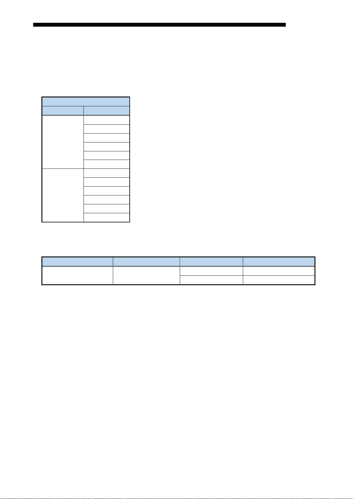
Section 2 SYSTEM CONFIGURATION
Attachable CPU Module
Attachable CPU Module
CPU Type
CPU Model
CPU Type
CPU Model
Programmable
R00CPU
Process CPU
R08PCPU
R01CPU
R16PCPU
R02CPU
R32PCPU
R120ENCPU
RE81WH
Section 2 SYSTEM CONFIGURATION
2.1 Precautions for system configuration
Attention to the following when configuring the system.
・Please install each modules so that the total number of occupied I/O points of these modules is equal to or less
than the number of I/O points of the CPU module used.
・Depending on the rated output current of the power supply used, mounting of the maximum number of
modules may not be possible. Consider the current consumption of each module to configure the system.
2.2 Applicable system
2.2.1 Applicable module
(1) CPU module
The CPU module that can install RE81WH is shown below.
For the number of mountable modules, refer to the "MELSEC iQ-R Module Configuration Manual".
RE81WH supports multiple CPU system.
controller CPU
R04CPU R120PCPU
R08CPU
R16CPU R16SFCPU
R32CPU R32SFCPU
R120CPU R120SFCPU
R04ENCPU C Controller module R12CCPU-V
R08ENCPU
R16ENCPU
R32ENCPU
Safety CPU R08SFCPU
11
Page 13
Section 2 SYSTEM CONFIGURATION
Type
Model
R35B
R38B
R312B
R310B
R310B-HT
R38RB-HT
Extension
R65B
R68B
R612B
R610RB
R610B-HT
RE81WH
(2) Base unit
The Base unit that can install RE81WH is shown below.
RE81WH can be installed to any I/O slot
*1 *2
.
*1 In case of Process CPU that operates in redundant mode, it can only be mounted with the extension
base unit. It is not allowed to be mounted with the main base unit.
*2 Limited within the range of I/O points for the CPU module.
Mountable Base unit
Main base
base
R68RB-HT
(3) Applicable software package
Software packages applicable to this module as follows.
Refer to the next page for the version of this module.
Product name Model name Remarks RE81WH version
GX Works3 Version1 SW1DND-GXW3-J
1.040S or later A
1.050C or later B
12
Page 14
Section 2 SYSTEM CONFIGURATION
Version
A
-
-
Version:A
Version:B
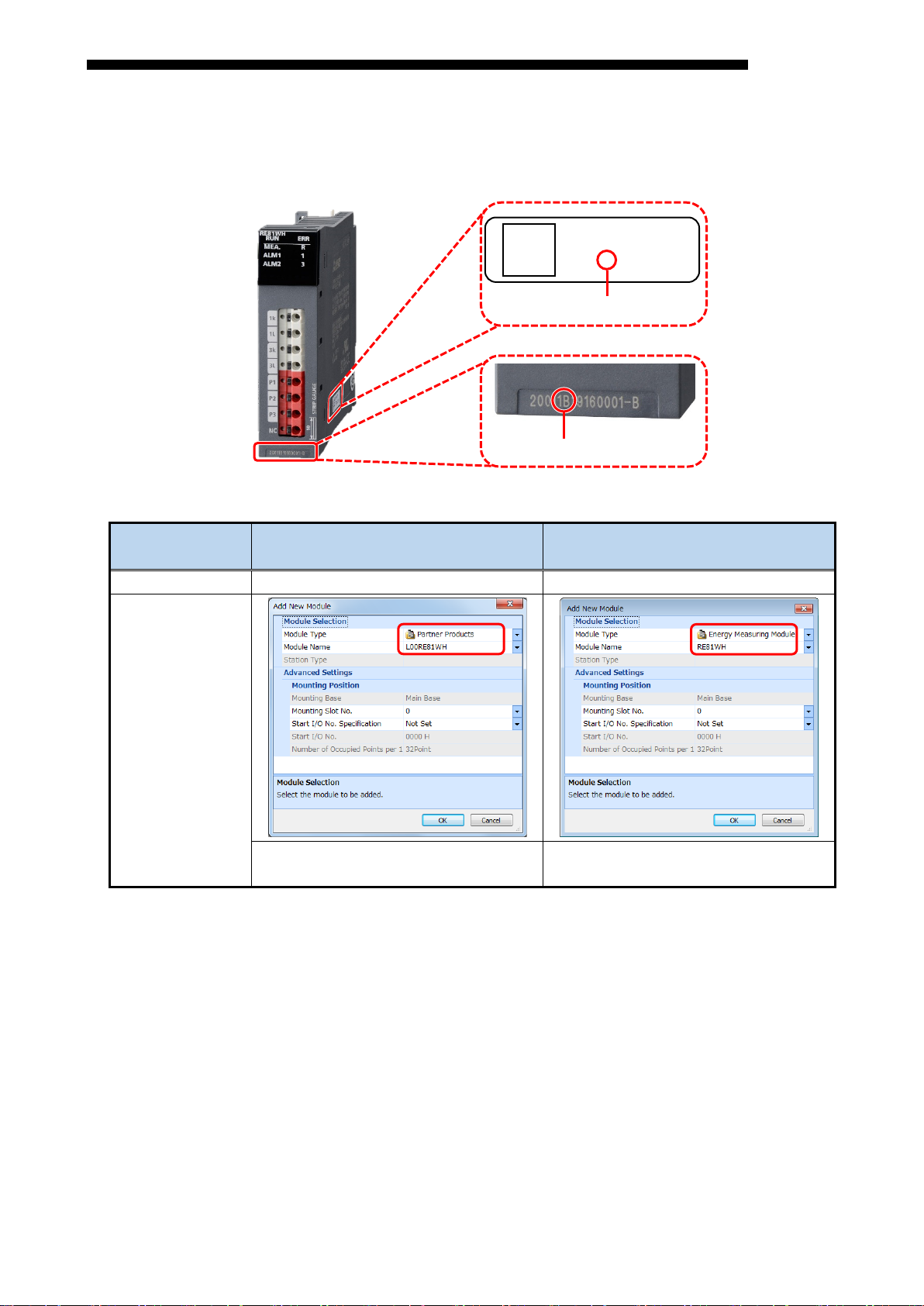
2.2.2 How to confirm the version of RE81WH
Confirm the version of RE81WH as below:
Refer to previous page for the software package corresponding to the each version.
○○○○○○
○○○B○○○○○
Version
Version
Changes for version of RE81WH
RE81WH
(Shipment start date)
Before After
B
(Nov, 2018)
Profile registration needed*
Profile registration unneeded
* When using version A on GX Works3, Profile (for MELSEC iQ-R series Energy Measuring Module
(RE81WH) profile) registration is needed
Refer to “GX Works3 operating manual” for registration of profile.
You can download the profile from the web site. (http://www.mitsubishielectric.com/fa/)
When using version B, Profile registration unneeded.
13
Page 15

Section 3 NAME AND FUNCTION OF EACH PART
(1) LED
Operating state of this
module is displayed.
(2) Current input terminals
Connect with the secondary
output of the dedicated
current sensor connected to
the current wire of the
measuring circuit.
(3) Voltage input terminals
Connect the voltage input
wire of the measuring circuit.
(6) Strip gauge
A gauge used for
checking the length of
stripped wire.
(5) Check hole
Use this for continuity
check to the terminal.
Use it with a tester
contact.
(4) Push button
Push this button to
insert a cable to the
terminal or remove it.
symbol
3L
3-phase current input terminal (load side)
P1
P3
1-phase voltage input terminal
3-phase voltage input terminal
NC
Unused
Section 3 NAME AND FUNCTION OF EACH PART
3.1 Name of each part
RE81WH
Figure 3.1-1 Appearance of the module
Table 3.1-1 The names and operations of terminal block
Terminal
1k
1L
3k
P2
1-phase current input terminal (power source side)
1-phase current input terminal (load side)
3-phase current input terminal (power source side)
2-phase voltage input terminal
Name of terminal
14
Page 16

Section 3 NAME AND FUNCTION OF EACH PART
Internal power supply is off, error is in
No measuring electric energy (no
In the case of alarm 1 reset method =
OFF: Alarm 2 not occurring
OFF: Normal operation
Displays the status of
measurement (regeneration)
of this module.
ON: Measuring electric energy (regeneration)
Displays the status of
measurement (regeneration)
ON: Measuring 1-phase electric energy
Displays the status of
measurement (regeneration)
phase electric energy
3.2 Indication and function of LEDs
The following describes names and functions of LEDs.
Table 3.2-1 Names and functions of LEDs
Name Color Role Indicator condition
RUN
LED
MEA.
LED
ALM1
LED
ALM2
LED
Displays the operation status
Green
of this module.
Displays measuring status of
Green
*2
this module.
Displays alarm 1 occurrence
status.
Red
Displays alarm 2 occurrence
status.
Red
ON: Normal operation
OFF:
occurrence in hardware. *1
ON: Measuring electric energy (consumption or
regeneration)
OFF:
measurement)
Flashing: Alarm 1 occurring
ON: Alarm 1 occurring → Not occurring
(
Self-retention)
OFF: Alarm 1 not occurring
Flashing: Alarm 2 occurring
ON: Alarm 2 occurring → Not occurring
(In the case of alarm 2 reset method = Self-
retention)
RE81WH
ERR
LED
R
LED
1
LED
3
LED
Displays error and the status
Red
Green
*2
Green
*2
Green
*2
of this module.
at side 1 of this module.
at side 3 of this module.
Flashing: Error in out of range of setting values
*1
ON: Error in occurrence in hardware
OFF: Other than the above
(regeneration)
OFF: Other than the above
ON: Measuring 3-
(regeneration)
OFF: Other than the above
*1: For details, refer to “8.1 List of error codes” in this manual.
*2: When calculated value is low, “MEA”LED, “R”LED, “1”LED and “3”LED are looked like flashing.
Comparing to the last value per measuring cycle, LEDs light while calculating, then LEDs light off upon
no changes.
Since measuring cycle is shortest as 10ms, short period setting seems like flashing.
*1
15
Page 17

Section 3 NAME AND FUNCTION OF EACH PART
(consumption, regeneration), reactive energy
), harmonic current, current harmonic
and sequentially stores the records into a buffer memory.
The electric energy only for a period of time when a
certain output signal is ON will be stored in the buffer
power factor, each maximum/minimum values and
date/time of occurrence are stored.
Upper/lower limit alarm
the specified input signal is turned on.
storage of the
Set the integrated value (electric energy (consumption,
regeneration), reactive energy (consumption lag)) to an
circuit into the buffer memory.
3.3 List of functions
Functions of RE81WH are provided in “Table 3.3-1 List of Functions”.
Table 3.3-1 List of Functions
No. Function Descriptions
It measures current, current demand, voltage, electric
power, electric power demand, Reactive power, apparent
power, power factor, frequency, effective energy
1 Measurement
(consumption lag
distortion, harmonic voltage, voltage harmonic distortion,
RE81WH
Reference
section
3.4.1
2 Periodic electric energy
3 Hold max./min. values
4
monitoring
5 Test
6 Integrated value set
7 Output of waveform data
memory.
Periodic energy 1 and 2 can be measured independently.
For current demand, voltage, electric power demand, and
Among current demand, voltage, electric power demand,
and power factor, you can select two measuring items for
which their upper/lower limit can be monitored.
If it exceeds the upper limit or goes below the lower limit,
Parameter setting enables pseudospecified value into the buffer memory, even with non-
existence of input from voltage and current (sensor).
Using this module, you can create a sequence, etc.
arbitrary value.
It is used to clear integrated value.
Stores waveform data of current / voltage of the measured
3.4.2
3.4.3
3.4.4
3.4.5
3.4.6
3.4.7
16
Page 18

Section 3 NAME AND FUNCTION OF EACH PART
Measured items
Details
period of current demand time is
Date of max. value occurrence
Date of min. value occurrence
Phase 1 harmonic current (n th)
Phase 1 harmonic current (Total)
Phase 3 harmonic current (n th) *1
Phase 3 harmonic current (Total) *1
Phase 1 current harmonic distortion (n th)
Phase 1 current harmonic distortion (Total)
Phase 3 current harmonic distortion (n th) *1
Phase 3 current harmonic distortion (Total) *1
RE81WH
3.4 Functions in detail
3.4.1 Measuring function
(1) Measured items
Measured items and measured ranges are described as follows.
Each measured item is stored in the buffer memory at every measuring cycle.
Refer to “5.2.12” for measuring cycle, and refer to “4.2.1(7)” for measuring cycle of harmonic current and
harmonic voltage.
Table 3.4.1-1 List of Measured items (1/2)
Current Phase 1 current
Phase 2 current*1
Phase 3 current*1
Average current
Current demand
* The average of fluctuation for the set
indicated.
Phase 1 current demand
Phase 2 current demand *1
Phase 3 current demand *1
Max. value
Min. value
Harmonic current *2
*1: If phase wire system is set to single-phase 2-wire, measurement will not be taken.
*2: The order of harmonic as follows.
RMS: 1st, 3rd, 5th, 7th, 9th, 11th, 13th, 15th, 17th, 19th
Distortion: 3rd, 5th, 7th, 9th, 11th, 13th, 15th, 17th, 19th
17
Page 19

Section 3 NAME AND FUNCTION OF EACH PART
Max. value
Min. value
Date/time of max. value occurrence
Date/time of min. value occurrence
1-2 harmonic voltage (n th)
1-2 harmonic voltage (Total)
2-3 harmonic voltage (n th) *1
2-3 harmonic voltage (Total) *1
1-2 voltage harmonic distortion (n th)
1-2 voltage harmonic distortion (Total)
2-3 voltage harmonic distortion (n th) *1
Apparent power
Apparent power
Max. value
Min. value
Date/time of max. value occurrence
Date/time of min. value occurrence
Frequency
Present value
Electric energy (consumption)
Electric energy (regeneration)
Reactive energy
Reactive energy (consumption lag)
Periodic electric energy
Periodic electric energy 1
Periodic electric energy 2
Table 3.4.1-1 List of Measured items (2/2)
Measured items
Details
Voltage 1-2 voltage (voltage V12)
2-3 voltage*1 (voltage V23)
3-1 voltage*1 (voltage V31)
Average voltage
Harmonic voltage *2
RE81WH
2-3 voltage harmonic distortion (Total) *1
Electric power Present value
Electric power demand
* The average of fluctuation for the set
period of electric power demand time
is indicated.
Reactive power Reactive power
Power factor Present value
Electric energy
Present value
Max. value
Min. value
Date/time of max. value occurrence
Date/time of min. value occurrence
*1: If phase wire system is set to single-phase 2-wire, measurement will not be taken.
*2: The order of harmonic as follows.
RMS: 1st, 3rd, 5th, 7th, 9th, 11th, 13th, 15th, 17th, 19th
Distortion: 3rd, 5th, 7th, 9th, 11th, 13th, 15th, 17th, 19th
18
Page 20

Section 3 NAME AND FUNCTION OF EACH PART
(The highest value after the max./min. value was reset.)
(The highest value after the max./min. value was reset.)
Highest value among 1-phase current demand, 2-phase current
(The highest value after the max./min. value was reset.)
Minimum
Minimum value of 1-phase current demand
(The lowest value after the max./min. value was reset.)
(The lowest value after the max./min. value was reset.)
phase current
(The lowest value after the max./min. value was reset.)
Maximum
Highest value of the 1 - 2 line voltage
(The highest value after the max./min. value was reset.)
(The highest value after the max./min. value was reset.)
(The lowest value after the max./min. value was reset.)
Lowest value of either the 1 - 2 line voltage or the 2 - 3 line voltage
(The lowest value after the max./min. value was reset.)
(2) Total, maximum, and minimum values
The following describes how to calculate the maximum, minimum, and total values.
Table 3.4.1-2 How to calculate the maximum, minimum and average values
Item Phase wire system Formula
Average
current
Average
voltage
Maximum
current
demand
single-phase 2-wire Average current = 1-phase current
single-phase 3-wire
three-phase 3-wire
single-phase 2-wire Average voltage = voltage V12
single-phase 3-wire
three-phase 3-wire
single-phase 2-wire
single-phase 3-wire
Average current = (1-phase current + 3-phase current) / 2
Average voltage = (voltage V12 + voltage V23) / 2
Maximum value of 1-phase current demand
Highest value of either 1-phase current demand or 3-phase current
demand
RE81WH
current
demand
voltage
Minimum
voltage
three-phase 3-wire
single-phase 2-wire
single-phase 3-wire
three-phase 3-wire
single-phase 2-wire
single-phase 3-wire
three-phase 3-wire
single-phase 2-wire
single-phase 3-wire
three-phase 3-wire
demand, or 3-phase current demand
Lowest value of either 1-phase current demand or 3-phase current
demand
Lowest value among 1-phase current demand, 2demand, or 3-phase current demand
Highest value of either the 1 - 2 line voltage or the 2 - 3 line voltage
Highest value among the 1 - 2 line voltage, the 2 - 3 line voltage, or
3 - 1 line voltage
(The highest value after the max./min. value was reset.)
Lowest value of the 1 - 2 line voltage
(The lowest value after the max./min. value was reset.)
Lowest value among the 1 - 2 line voltage, the 2 - 3 line voltage, or
3 - 1 line voltage
19
Page 21

Section 3 NAME AND FUNCTION OF EACH PART
decimal point
1 digit after the
decimal point
400 A ≤ PA < 4000 A
-3
Integer
1 A
4000 A ≤ PA
-3
x10
10 A
PV*1
factor
1 digit after the
3300 V ≤ PV
-3
x10
10 V
factor
decimal point
1 digit after the
decimal point
IV
1200 kW ≤ W < 12000 kW
-3
Integer
1 kW
V
12000 kW ≤ W < 120000 kW
-3
x10
10 kW
RE81WH
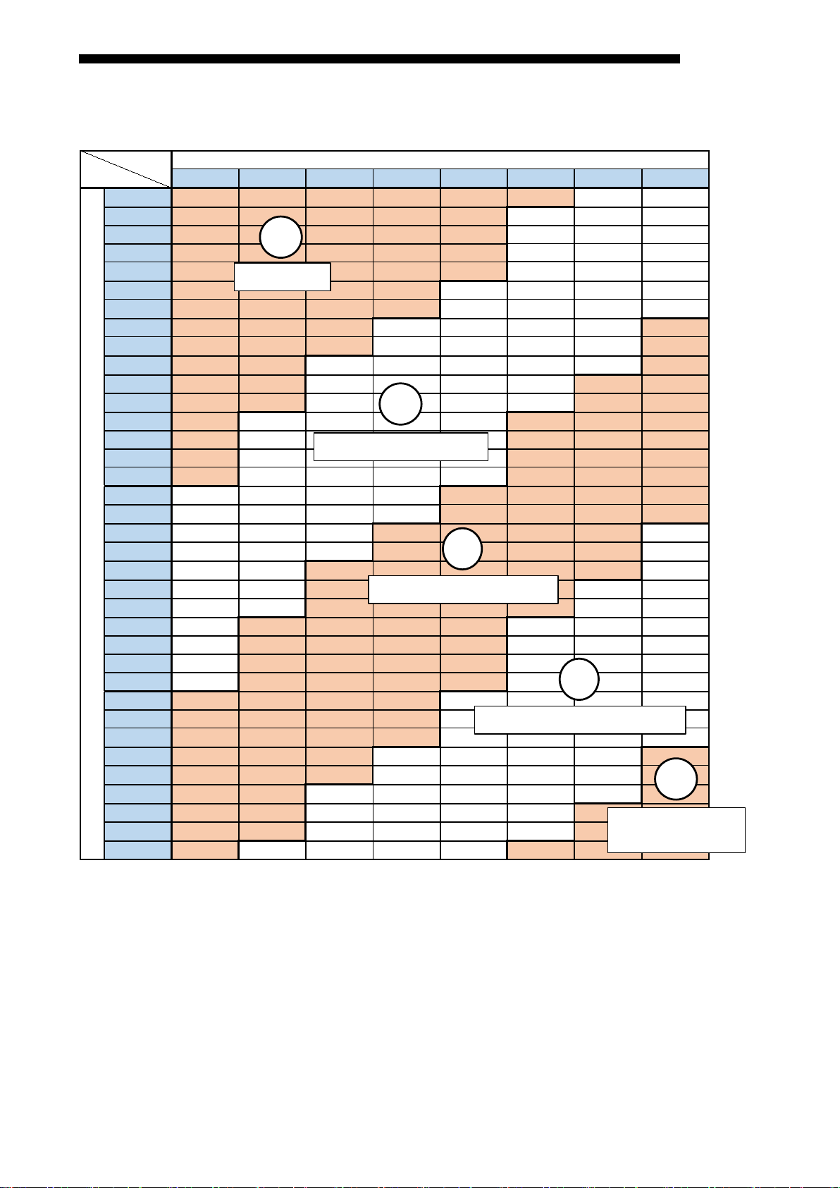
(3) Resolution of measured data
Resolution of measured data according to the rating (phase wire system, primary voltage setting, and
primary current setting) is described as follows.
(a) Current, current demand
Primary current setting
PA*1
PA < 40 A -3
Multiplying
factor
Resolution*2
2 digits after the
0.01 A
40 A ≤ PA < 400 A -3
0.1 A
*1: Case of setting value of the primary current (Un\G2) is “0”, the primary current (PA) is value of
primary current of CT (Un\G7).
In other cases, the primary current (PA) is the value of primary current (Un\G2).
*2: Digits lower than the resolution are fixed to 0.
(b) Voltage
Primary voltage setting
PV < 330 V -3
Multiplying
Resolution*2
decimal point
0.1 V
330 V ≤ PV < 3300 V -3 Integer 1 V
*1: Case of setting value of the primary voltage (Un\G1) is “0”, the primary voltage (PV) is value of
primary voltage of VT (Un\G5).
In other cases, the primary voltage (PV) is the value of primary voltage (Un\G1).
*2: Digits lower than the resolution are fixed to 0.
(c) Electric power, electric power demand, Reactive power, Apparent power
Full load power W*1
Multiplying
Resolution
*2 *3
I W < 12 kW -3
II 12 kW ≤ W < 120 kW -3
III 120 kW ≤ W < 1200 kW -3
*1: Full load power (W) can be calculated by the following formula.
For calculating full load power W, refer to “Table 3.4.1-3 How to calculate full load power”.
Full load power W(kW) = α × Primary voltage (V) × Primary current (A) / 1000
Case of single-phase 2-wire: α = 1
Case of single-phase 3-wire: α = 2
Case of three-phase 3-wire: α = 3
*2: Digits lower than the resolution are fixed to 0.
*3: The module is kvar for reactive power and kVA for apparent power.
3 digits after the
decimal point
2 digits after the
0.001 kW
0.01 kW
0.1 kW
20
Page 22

Section 3 NAME AND FUNCTION OF EACH PART
decimal point
factor
decimal point
factor
5 digits after the
decimal point
3 digits after the
decimal point
decimal point
(d) Power factor
Power factor
All setting ranges -3
Multiplying
factor
Resolution*1
1 digit after the
*1: Digits lower than the resolution are fixed to 0.
(e) Frequency
Frequency
Multiplying
Resolution*1
RE81WH
0.1 %
All setting ranges -3
1 digit after the
0.1 Hz
*1: Digits lower than the resolution are fixed to 0.
(f) Electric energy, reactive energy, periodic electric energy
Full load power W*1
Multiplying
I W < 12 kW -5
II 12 kW ≤ W < 120 kW -4
III 120 kW ≤ W < 1200 kW -3
IV 1200 kW ≤ W < 12000 kW -2
V 12000 kW ≤ W < 120000 kW -1
Resolution
decimal point
4 digits after the
2 digits after the
decimal point
1 digit after the
*2 *3
0.00001 kWh
0.0001 kWh
0.001 kWh
0.01 kWh
0.1 kWh
*1: Refer to “(c) *1” about how to calculate Full load power (W).
For calculating full load power W, refer to “Table 3.4.1-3 How to calculate full load power”.
*2: Because the higher resolution than a typical watt-hour meter, the minimum digit values will change
more than 2 at once update in accordance with setting value of input voltage, primary current,
primary voltage of VT, secondary voltage of VT, primary current of CT and the condition of load.
*3: In the case of reactive energy, the unit will be kvarh.
21
Page 23
Section 3 NAME AND FUNCTION OF EACH PART
110 220 440 690 1100 2200 3300 6600
5
6
7.5
8
10
12
15
20
25
30
40
50
60
75
80
100
120
150
200
250
300
400
500
600
750
800
1000
1200
1500
1600
2000
2500
3000
4000
5000
6000
Primary current [A]
Primary voltage [V]
Ⅰ
Ⅱ
Ⅴ
W < 12 kW
12 kW ≤ W < 120 kW
120 kW ≤ W < 1200 kW
1200 kW ≤ W < 12000 kW
12000 kW ≤ W
< 120000 kW
Table 3.4.1-3 How to calculate full load power
Single-phase 2 wire system
RE81WH
22
Page 24

Primary voltage [V]
110
5
6
7.5
8
10
12
15
20
25
30
40
50
60
75
80
100
120
150
200
250
300
400
500
600
750
800
1000
1200
1500
1600
2000
2500
3000
4000
5000
6000
Primary current [A]
Ⅰ
W < 12 kW
Ⅱ
12 kW ≤ W < 120 kW
120 kW ≤ W < 1200 kW
1200 kW ≤ W < 12000 kW
Section 3 NAME AND FUNCTION OF EACH PART
Single-phase 3-wire system
RE81WH
23
Page 25

Section 3 NAME AND FUNCTION OF EACH PART
110 220 440 690 1100 2200 3300 6600
5
6
7.5
8
10
12
15
20
25
30
40
50
60
75
80
100
120
150
200
250
300
400
500
600
750
800
1000
1200
1500
1600
2000
2500
3000
4000
5000
6000
Primary current [A]
Primary voltage [V]
Ⅰ
W < 12 kW
Ⅱ
12 kW ≤ W < 120 kW
120 kW ≤ W < 1200 kW
1200 kW ≤ W < 12000 kW
Ⅴ
12000 kW ≤ W
< 120000 kW
Three-phase 3-wire system
RE81WH
24
Page 26

Section 3 NAME AND FUNCTION OF EACH PART
Measuring item
Behavior of the module
Current
When the input current is less than 0.4% of the rating current, it becomes 0A.
is 0A, current demand may not be 0A.
Indicate “0 A” if 1-2 line voltage is 0V.
Frequency condition:
Indicate “0 %” at each phase if harmonic current (Harmonic current (1st)) is 0A.
Indicate “0 %” if 1-2 line voltage is 0V.
When it is less than 44.5Hz, it becomes 0V.
When it is less than 44.5Hz, it becomes 0V.
Apparent power
* The unit is kvar for reactive power and kVA for apparent power.
Electric power
Electric power demand is obtained by electric power moving average. Therefore,
are 0V), it becomes 100%
When it is less than 44.5Hz, it is fixed to 44.5Hz.
RE81WH
(4) Restrictions for measuring data
・Measurement cannot be performed immediately after the power loading to the sequencer system
(Module ready signal is under the OFF condition).
After checking that Module ready (Xn0) is ON, obtain measuring data.
・Measurement cannot be performed immediately after operating conditions are set up to the module. After
checking that Operating condition setting completion flag (Xn9) becomes ON, obtain measuring data.
・Behaviors during operation are as follows.
Current demand Current demand is obtained by current moving average. Therefore, even if the current
Harmonic current Current condition:
Indicate “0 A” at each phase if current is 0A.
Voltage condition:
Indicate “0 A” at all phase if frequency is under 44.5Hz.
Current harmonic
distortion
Harmonic current condition:
Voltage condition:
Frequency condition:
Indicate “0 %” at all phase if frequency is under 44.5Hz.
Voltage Indicate “0 V” if RMS value is under 11V. (*1)
Harmonic voltage Voltage condition:
Indicate “0 V” at each inter-wire if voltage is 0V.
Indicate “0 V” if 1-2 line voltage is 0V.
Frequency condition:
Voltage harmonic
distortion
Electric power,
Reactive power,
demand
Electric energy The electric energy is measured with a load that is about 0.4% or more of all load
Power factor When current is 0A (at all phases are 0A) or when voltage is 0V (all in-between wires
Voltage condition:
Indicate “0 %” at each inter-wire if voltage is 0V.
Indicate “0 %” if 1-2 line voltage is 0V.
Frequency condition:
When current is 0A (at all phases are 0A) or when voltage is 0V (all in-between wires
are 0V), it becomes 0kW.
even if electric power is 0kW, electric power demand may not be 0kW.
power. Even if the indicated value is “0”, measurement value will increase.
Frequency Voltage condition
Indicate “0 Hz” if 1-2 line voltage is 0 V.
Frequency condition
*1: In 1-phase three-wire system, indicate “0 V” if RMS value is under 22V.
25
Page 27

Section 3 NAME AND FUNCTION OF EACH PART
Periodic
RE81WH
3.4.2 Measuring function for periodic electric energy
This function is to measure electric energy (consumption) for a certain period, and stores it into the buffer
memory. It can be used to measure electric energy for a certain tact or energy (standby power) when the facility
or equipment is not in operation.
(1) Overview
(a) It can measure two periodic electric energy at maximum (periodic electric energy 1, periodic electric
energy 2). Each of these can be measured independently.
(b) While the time when Periodic electric energy 1 measurement flag (Yn1)/ Periodic electric energy 2
measurement flag (Yn2) is ON, periodic electric energy can be measured.
(c) Since Periodic electric energy is stored in the nonvolatile memory, it can be retained even when a power
source reset.
(d) I/O signals and buffer memory corresponding to each of periodic electric energy 1 and 2 are shown
below.
Periodic
electric energy
1
Periodic
electric energy
2
Supplement
Quantity survey of periodic electric energy is performed every measuring cycle. Therefore, if the
time for turning ON Periodic electric energy 1 measurement flag (Yn1) and Periodic electric energy
2 measurement flag (Yn2) is set to measuring cycle or less, measurement may not be performed.
For the measuring cycle, refer to “5.2.12”.
Buffer memory
(Double words)
Un\G114,115
Un\G116,117
electric
energy
measurement
flag
Yn1 Xn1 Yn3 Xn3
Yn2 Xn2 Yn4 Xn4
Periodic electric
energy data
completion flag
Periodic
electric
energy reset
request
Periodic electric
completion flag
energy reset
26
Page 28
Section 3 NAME AND FUNCTION OF EACH PART
Period ic ele ctric en ergy 1
OFF
Period ic ele ctric en ergy 1 reset reques t (Yn3)
Period ic ele ctric en ergy 1 reset com pletion flag (Xn3)
(i) (ii)
ON
ON
OFF
OFF
(iii)
Period ic ele ctric en ergy 1 me asuremen t flag (Yn1)
Period ic ele ctric en ergy 1 data co mple tio n flag (Xn1)
ON
OFF
ON
OFF
Period ic ele ctric en ergy 1
ON
OFF
(i) (ii)
(iii) (iv) (v)
RE81WH
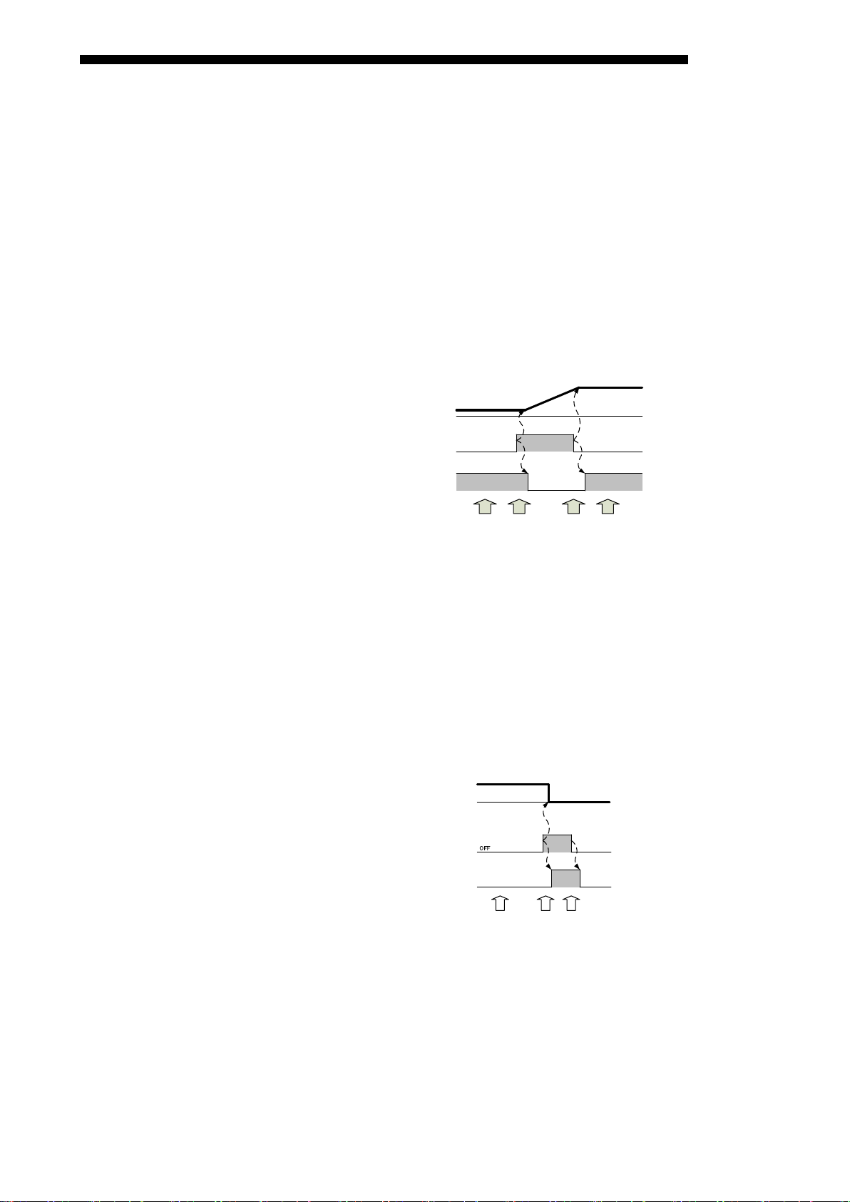
(2) Basic procedure
(a) Measuring periodic electric energy
(i) Check that Periodic electric energy measurement flag (Yn1/Yn2) i s O F F.
(ii) Check periodic electric energy (Un\G114, 115/Un\G116, 11 7).
(iii) When starting measurement, set Periodic electric energy measurement flag (Yn1/Yn2) to ON.
This module starts measuring specified periodic electric energy, and Periodic electric energy data
completion flag (Xn1/Xn2) will be turned OFF.
(iv) When stopping measurement, set Periodic electric energy measurement flag (Yn1/Yn2) to OFF.
This module stops measuring the specified periodic electric energy, and Periodic electric energy data
completion flag (Xn1/Xn2) will be turned ON.
(v) Check that Periodic electric energy data completion flag (Xn1/Xn2) becomes ON, and obtain the
value of periodic electric energy.
Figure 3.4.2-1 Basic procedure of measuring the periodic electric energy 1
(b) Resetting periodic electric power
(i) Check that Periodic electric energy measurement flag (Yn1/Yn2) is OFF and Periodic electric energy
reset request (Yn3/Yn4) is OFF.
(ii) Set Periodic electric energy reset request (Yn3/Yn4) to ON. The specified periodic electric energy is
reset to 0 kWh, and Periodic electric energy reset completion flag (Xn3/Xn4) will be turned to ON.
(iii) Check the Periodic electric energy reset completion flag (Xn3/Xn4) has become ON, then set Periodic
electric energy reset request (Yn3/Yn4) to OFF.
Periodic electric energy reset completion flag (Xn3/Xn4) will be turned OFF.
Figure 3.4.2-2 How to reset the periodic electric energy 1
27
Page 29

Section 3 NAME AND FUNCTION OF EACH PART
Periodic ele ctric energy 1 me asure ment f lag (Yn1)
Periodic ele ctric energy 1 dat a com ple tion flag (Xn1)
ON
OFF
OFF
OFF
Periodic ele ctric energy 1
ON
Period ic ele ctric energy 1 me asure ment f lag (Yn1)
Period ic ele ctric energy 1 data comple tio n flag (Xn1)
ON
OFF
ON
OFF
Period ic ele ctric energy 1
ON
OFF
Period ic ele ctric energy 1 res et request (Yn3)
Period ic ele ctric energy 1 res et com pletion fla g (Xn3)
(i) (ii)
ON
OFF
OFF
(iii) (iv) (v) (vi)
RE81WH
(3) Example of use
(a) Procedure for continuously measuring periodic electric energy
If you turn Periodic electric energy measurement flag (Yn1/Yn2) to ON only while measurement is
needed, this module accumulates the power starting at the previously measured amount. Usage
procedure is the same as (a) in (2).
An example is shown below.
Figure 3.4.2-3 Example of continuous measurement of periodic electric energy 1
(b) Procedure for measuring periodic electric energy at every reset
By the following usage procedure, this module accumulates electric energy every time after resetting
periodic electric energy.
(i) Check that Periodic electric energy measurement flag (Yn1/Yn2) is OFF and Periodic electric energy
reset request (Yn3/Yn4) is OFF.
(ii) Set Periodic electric energy reset request (Yn3/Yn4) to ON.
The specified periodic electric energy is reset to 0 kWh, and Periodic electric energy reset completion
flag (Xn3/Xn4) will be turned ON.
(iii) Check that Periodic electric energy reset completion flag (Xn3/Xn4) has become ON, and then set
Periodic electric energy reset request (Yn3/Yn4) to OFF.
Periodic electric energy reset completion flag (Xn3/Xn4) will be turned OFF.
(iv) When starting measurement, set Periodic electric energy measurement flag (Yn1/Yn2) to ON.
This module starts measuring the specified periodic electric energy, and Periodic electric energy data
completion flag (Xn1/Xn2) will be turned OFF.
(v) When stopping measurement, set Periodic electric energy measurement flag (Yn1/Yn2) to OFF.
This module stops measuring the specified periodic electric energy, and Periodic electric energy data
completion flag (Xn1/Xn2) will be turned ON.
(vi) Check that Periodic electric energy data completion flag (Xn1/Xn2) becomes ON, and obtain the
value of periodic electric energy.
Figure 3.4.2-4 Example of measurement of periodic electric energy 1 every time after resetting
28
Page 30

Section 3 NAME AND FUNCTION OF EACH PART
Setting value
Description
11
Current demand
12
Voltage
Max./min. value s clea r re qu es t (YnD)
Max./min. value s clea r completion flag (XnD)
ON
ON
OFF
OFF
RE81WH
3.4.3 Max./min. value hold function
It memorizes the max./min. value for each measuring item, and retains them until the max./min. value clear
are performed.
(1) Max./min. value memory
It memorizes the max. and min. values, and the time of occurrence (year/month/day/hour/minute/second/day
of the week/millisecond) values for the following measuring item.
* The max. and min. values and the date of occurrence are stored in the nonvolatile memory, so that these
values can be retained even when a power source reset.
・Current demand
・Voltage
・Electric power demand
・Power factor
(2) How to clear the max. and min. values
You can use the I/O signal to clear the max. and min. values that specified by max./min. values clear target
(Un\G56).
The max. and min. values immediately after the clear becomes the present values and the date of
occurrence will be the present date and time.
The following describes how to clear the max. and min. values.
(a) Check that Max./min. values clear request (YnD) is O F F.
(b) Set the max./min. values clear target(Un\G56).
The setting range is shown below.
13 Electric power demand
14 Power factor
19 All of the above
Others Do not clear
(c) Set Max./min. values clear request (YnD) to ON.
This module clears the max./min. values set by (b), and the date of occurrence, and set Max./min.
values clear completion flag (XnD) to ON.
(d) Check that Max./min. values clear completion flag (XnD) is ON, and then set Max./min. values clear
request (YnD) t o O F F.
Max./min. values clear completion flag (XnD) will be turned OFF.
Figure 3.4.3-1 Procedure for clearing max./min. value
29
Page 31

Section 3 NAME AND FUNCTION OF EACH PART
(Alarm 1 / Alarm 2)
8: Power factor lower limit
For respective alarm 1 and
Alarm monitoring
-2147483648 – 2147483647
Power factor :×10-3 %
The value to be monitored for
the alarm. Set the value
according to the unit of the
(Double words)
Alarm reset method
0: Self-retention
Set whether or not the alarm-
the upper limit alarm value or
Only when the state that it
exceeds the upper limit alarm
monitoring value or it goes
below the lower limit alarm
monitoring value continues for
it is considered as an alarm
occurrence.
RE81WH
3.4.4 Upper/lower limit alarm monitoring function
You can set an upper and lower limit alarm for maximum two points and implement a monitoring function for
them.
During the alarm monitoring, you can check the alarm occurrence by the input signal.
(1) Setting items of the upper/lower limit alarm monitoring
Setting items and setting range for the alarm monitoring are described below.
Items set in the
buffer memory
Setting range Description
Alarm monitoring
factor
(Un\G11 / Un\G21)
value
(Un\G12,13
/ Un\G22,23)
(Un\G14 / Un\G24)
Alarm delay time
(Un\G15 / Un\G25)
0: No monitoring
1: Current demand upper limit
2: Current demand lower limit
3: Voltage upper limit
4: Voltage lower limit
5: Power demand upper limit
6: Power demand lower limit
7: Power factor upper limit
[Unit]
Current demand :×10
Voltage :×10
Electric Power demand :×10
1: Self-reset
0 – 300
[Unit] second
-3
A
-3
V
-3
kW
alarm 2, set the monitoring item
either the upper / lower limit or
measuring factor.
measuring item that is set as an
alarm monitoring factor.
occurrence condition should be
retained if the value goes below
goes over the lower limit alarm
value after the upper/lower limit
alarm occurred.
* Each item of the alarm monitoring is stored in the nonvolatile memory, so that values can be retained even
when a power source reset.
the period of alarm delay time,
30
Page 32

Section 3 NAME AND FUNCTION OF EACH PART
ON
OFF
OFF
ON
OFF
OFF
Operating condition setting completion flag (Xn9)
Operating condition setting request (Yn9)
Alar m 1 flag (XnA )
OFF
ON
Ala rm
del ay t ime
ON
Alar m 1 res et r equest (YnA)
OFF
ALM1 LED
OFF Flashing OFFON
(i)
(ii)
(iii) (iv)
Upper limit
RE81WH
(2) How to set the upper/lower limit alarm monitoring
Setting procedures are as following.
(a) Check that Operating condition setting request (Yn9) is OFF.
(b) Set the alarm item in the buffer memory (Un\G11 / Un \G21), alarm value (Un\G12, 13 / Un\G22, 23),
alarm reset method (Un\G14 / Un\G24), and alarm delay time (Un\G15 / Un\G25).
(c) Set Operating condition setting request (Yn9) to ON.
Operation starts at each set value, and then, Operating condition setting completion flag (Xn9) is turned
ON.
(d) Check that Operating condition setting completion flag (Xn9) becomes ON, and then set Operating
condition setting request (Yn9) to OFF.
Operating condition setting completion flag (Xn9) will be turned OFF.
Figure 3.4.4-1 Time chart of alarm monitoring setting
(3) Behavior of the upper/lower limit alarm
(a) When the alarm reset method is in the “0: Self-retention” setting (example of an upper limit monitoring
at alarm 1)
(i) If the measured value that was set with the alarm 1 monitoring item exceeds the upper limit and the
situation continues and remains for the alarm 1 delay time, Alarm 1 flag (XnA) will be turned ON.
At the same time, ALM1 LED flashes.
(ii) Even if the measured value goes below the upper limit, Alarm 1 flag (XnA) retains an ON status (Self-
retention).
During the self-retention, ALM1 LED is turned on.
(iii) By turning Alarm 1 reset request (YnA) to ON, Alarm 1 flag (XnA) will be turned OFF.
At this time, ALM1 LED is turned off.
(iv) Check that Alarm 1 flag (XnA) becomes OFF, and then set Alarm 1 reset request (YnA) to OFF.
Figure 3.4.4-2 Time chart of the upper/lower limit alarm (alarm reset method = “Self-retention”)
31
Page 33

Section 3 NAME AND FUNCTION OF EACH PART
Alar m 1 flag (XnA )
ON
Ala rm
del ay t ime
Ala rm
del ay t ime
ALM1 LED
OFF Flashing OFF
(i)
(ii)
(iii)
Upper limit
Alar m 2 flag (XnB )
OFF
ON
Ala rm
del ay t ime
Ala rm
del ay t ime
ALM2 LED
OFF Flashing OFF
(i)
(ii)
(iii)
Lower limit
RE81WH
(b) When the alarm reset method is in the “1: Self-reset” setting (example of an upper limit monitoring at
alarm 1)
(i) If the measured value that was set with the alarm 1 monitoring factor exceeds the upper limit and the
situation continues and remains for the alarm 1 delay time, Alarm 1 flag (XnA) will be turned ON.
At the same time, ALM1 LED flashes.
(ii) If the measured value goes below the upper limit, Alarm 1 flag (XnA) will be turned OFF. At this time,
ALM1 LED is turned off.
(iii) When the measured value that was set with the alarm 1 monitoring item goes below the upper limit
within the alarm 1 delay time even though the measured value exceeds the upper limit, the alarm 1
flag (XnA) will remain in OFF status.
Figure 3.4.4-3 Time chart of the upper/lower limit alarm (alarm reset method = “Self-reset”)
(c) When the alarm reset method is in the “Self-reset” setting (Example of a lower limit monitoring at alarm
2)
(i) If the measured value that was set with the alarm 2 monitoring factor goes below the lower limit and
the situation continues and remains for the alarm 2 delay time, Alarm 2 flag (XnB) will turn ON.
At the same time, ALM2 LED flashes.
(ii) If the measured value exceeds the lower limit, Alarm 2 flag (XnB) will turn OFF. At this time, ALM2
LED is turned off.
(iii) When the measured value that was set with the alarm 2 monitoring item exceeds the lower limit within
the alarm 2 delay time even though the measured value goes below the lower limit, the Alarm 2 flag
(XnB) will remain in OFF status.
Figure 3.4.4-4 Time chart of the upper/lower limit alarm (alarm reset method = “Self-reset”)
32
Page 34

Section 3 NAME AND FUNCTION OF EACH PART
Alar m 1 flag (XnA )
ON
ON
OFF
Alar m 1 res et request (YnA)
ALM1 LED
OFF Flashing OFF
(ii) (iii) (iv)(i) (v)
ON
Upper limit
Flashing
Ala rm
del ay t ime
Ala rm
del ay t ime
RE81WH
(4) How to reset Alarm flag
When Alarm flag is ON during the alarm occurrence or the self-retention (in the case of the alarm reset
method = “Self-retention“), Alarm flag can be reset (turned OFF) using Alarm reset request.
(a) How to reset Alarm flag during alarm occurrence (example of the upper limit alarm monitoring with the
alarm 1)
(i) If the measured value that was set with the alarm 1 monitoring factor exceeds the upper limit, Alarm
1 flag (XnA) will turn ON.
At the same time, ALM1 LED flashes.
(ii) By turning Alarm 1 reset request (YnA) to ON, Alarm 1 flag (XnA) will turn OFF.
At this time, ALM1 LED will remain flashing (because ALM1 LED is synchronized with the alarm
status, it will not turn off).
(iii) Check that Alarm 1 flag (XnA) becomes OFF, and then set Alarm 1 reset request (YnA) to OFF.
(iv) If the measured value goes below the upper limit, ALM1 LED will turn off.
(v) After that, if the measured value exceeds the upper limit, Alarm 1 flag (XnA) will turn ON again. At
the same time, ALM1 LED flashes.
(b) How to reset Alarm flag during self-retention (only in the case the alarm reset method = “Self-retention”)
Refer to the procedure described in (3)(a).
(5) Precautions during the alarm monitoring
When current demand time and electric power demand time are set to anytime other than 0 second, current
demand value and electric power demand value become lower than the actual values (closer to 0)
immediately after the power source ON and the CPU reset.
When current demand value and electric power demand value are being monitored for their lower limit alarm,
the alarm occurrence flag may turn ON. Thus, to avoid this, follow the procedure below.
(a) Set the alarm monitoring target to “no monitoring” immediately after the power source ON and the CPU
reset.
(b) After passing for a 3-times longer period than the demand time, set the alarm monitoring target again,
and start the alarm monitoring.
Figure 3.4.4-5 Procedure for resetting Alarm 1 flag (alarm reset method = “Self-reset”)
33
Page 35

Section 3 NAME AND FUNCTION OF EACH PART
operation before running the sequence program.
RE81WH
3.4.5 Tes t function
This function is to output pseudo-fixed value to a buffer memory for debugging sequence program. The value
can be output to the buffer memory without input of voltage and current.
Caution
● Because fixed-value is output to the buffer memory, separate the actual device to avoid unexpected
(1) How to use the test function
Using the parameter setting, you can start the test mode to output the fixed value.
Refer to “6.4.2” for procedure of the parameter setting, refer to “6.4.5” for start or end the test mode.
(2) Content of pseudo-output
For the value to be output to the buffer memory, refer to Table 5.1-1 to 5.1-3 in “5.1 Buffer memory
assignment”.
(3) LED display when using the test function
All LED ON.
(4) I/O signals when using the test function
Unit READY (Xn0) only ON.
Other input and output signals are all OFF.
34
Page 36

Section 3 NAME AND FUNCTION OF EACH PART
1
Electric energy (consumption)
2
Electric energy (regeneration)
3
Reactive energy (consumption lag)
積算値
セット
要求(Y3)
積算値セット完了 フラグ(X3)
ON
OFF
OFF
ON
OFF
OFF
RE81WH
3.4.6 Integrated value set function
This is a function that can set the integrated value (electric energy (consumption, regeneration), reactive
energy (consumption lag)) to an arbitrary value.
It is used to clear integrated value.
(1) Setting procedure
Setting procedures are as follows.
(a) Set the integrated value setting target (Un\G51) in the buffer memory.
Setting range is as follows.
Setting value Description
0 No set
(b) Set the integrated value setting value (Un\G52, 53) in the buffer memory.
・Configurable range: 0 to 999999999
・The unit used for the setting value is the same as that used for the electric energy and reactive
energy output to the buffer memory.
For details, refer to “5.3.2”.
(c) Turn Integrated value set request (YnC) from OFF to ON to enable the setting.
Integrated value set completion flag (XnC) turns ON after Integrated value set request (YnC) is set OFF
to ON.
(d) After checking that integrated value set completion flag (XnC) turns ON and setting is completed, set
the integrated value set request (YnC) t o OF F.
After detected that the integrated value set request (YnC) turns OFF, the integrated value set completion
flag (XnC) turns OFF.
Integrated value set request (YnC )
Integrated value set completion flag (XnC)
Figure 3.4.6 Integrated value setting procedure
(2) Default value
Integrated value setting target (Un\G51) is set to 0 (No set).
Integrated value setting value (Un\G52, 53) is set to 0.
35
Page 37

Section 3 NAME AND FUNCTION OF EACH PART
Measured items
Details
waveform data of 1-2 line voltage
waveform data of 2-3 line voltage*1
waveform data of 1-phase current
waveform data of 3-phase current*1
RE81WH
3.4.7 Waveform data output function
Waveform data is sampling data of current / voltage waveform of the measured circuit. Using this data, it is
possible to display the waveform, obtain changes of waveform. (Each data is converted value as unit V, A)
Waveform data is stored into the buffer memory in two methods as below.
* Waveform data to be measured is same, whereas buffer memory for storing data different.
(1) Waveform data sampled during period of measured data acquisition clock is stored into the buffer
memory.
The waveform data is stored into the buffer memory per period of measured data acquisition clock.
The buffer memory for storing multiple waveform data is secured. Waveform data sampled per sampling
period (254μs) during period of measured data acquisition clock is collectively stored into the buffer memory.
This method is used for acquiring waveform data synchronized with period of measured data acquisition
clock.
Refer to “4.2.1(8)” for synchronizing method.
(a) Measuring items
waveform data of voltage
waveform data of current
(b) Number of waveform data
The number of each waveform data to be stored is the number of sampling during period of measured
data acquisition clock.
Since the sampling period is not synchronized with the period of measured data acquisition clock, the
number of waveform data may be different even in the same period of measured data acquisition clock.
Thus, the number of each waveform data is stored into the buffer memory separately from the waveform
data.
(c) Restrictions for waveform data:
・It is impossible to obtain waveform data immediately after applying power to programmable controller
system. (Module ready OFF state)
Obtain waveform data after confirming “Module ready ON state”.
・It is impossible to obtain waveform data immediately after setting operating condition of this device.
Obtain waveform data after confirming “operating condition setting completed flag” is ON.
・Set the period of measured data acquisition clock below 50ms.
Where the period is larger than 50ms, waveform data is not stored into the buffer memory.
・It is possible to occur communication error inside the RE81WH due to disturbance noise (parallel noise
to CT line). When a communication error is occurred (when a communication error flag indicates error),
waveform data during the period of measured data acquisition clock is not stored into the buffer memory.
Instead “0” is stored into the buffer memory.
36
Page 38

Section 3 NAME AND FUNCTION OF EACH PART
ontinuous waveform
data of voltage and
RE81WH
(2) The waveform data is stored into the buffer memory per sampling period.
The waveform data is stored into the buffer memory per sampling period (μs) of the waveform data.
This method is used for acquiring the waveform data synchronized with sampling period.
Refer to “4.2.1(6)” for synchronizing method.
(a) Measured items
Measured items
Details
C
current
*1: When setting single phase 2-wire system for phase wire system, no measuring is performed.
(b) Number of waveform data
The number of each waveform data to be stored into buffer memory at once is one.
(c) Restrictions for waveform data
・It is impossible to obtain waveform data immediately after applying power to programmable controller
system. (Module ready OFF state)
Obtain waveform data after confirming “Module ready ON state”.
・It is impossible to obtain waveform data immediately after setting operating condition of this device.
Obtain waveform data after confirming “operating condition setting completed flag” is ON.
・It is possible to occur communication error inside the RE81WH due to disturbance noise (parallel noise
to CT line). When a communication error is occurred (when a communication error flag indicates error),
waveform data during the period of measured data acquisition clock is not stored into the buffer memory.
(In this case, the last waveform data is stored into the buffer memory)
waveform data of 1-2 line voltage
waveform data of 2-3 line voltage*1
waveform data of 1-phase current
waveform data of 3-phase current*1
37
Page 39

Section 4 I/O SIGNALS TO CPU MODULE
Input signal
(signal direction from RE81WH to CPU module)
Output signal
(signal direction from CPU module to RE81WH)
Device
No.
Device
No.
Periodic electric energy 1 data
completion flag
Periodic electric energy 1 measurement
flag
Periodic electric energy 2 data
completion flag
Periodic electric energy 2 measurement
flag
Periodic electric energy 1 reset
completion flag
Periodic electric energy 2 reset
completion flag
Xn6
Waveform data acquisition clock
Yn6
Use prohibited *1
Measured harmonics data acquisition
clock
Xn8
Measured data acquisition clock
Yn8
Use prohibited *1
Operating condition setting completion
flag
XnA
Alarm 1 flag
YnA
Alarm 1 reset request
XnB
Alarm 2 flag
YnB
Alarm 2 reset request
XnC
Integrated value set completion flag
YnC
Integrated value set request
XnD
Max./min. values clear completion flag
YnD
Max./min. values clear request
XnE
Use prohibited *1
YnE
Use prohibited *1
XnF
Error flag
YnF
Error clear request
Xn10
Use prohibited *1
Yn10
Use prohibited *1
Xn11
Use prohibited *1
Yn11
Use prohibited *1
Xn12
Use prohibited *1
Yn12
Use prohibited *1
Xn13
Use prohibited *1
Yn13
Use prohibited *1
Use prohibited *1
Use prohibited *1
Xn1C
Use prohibited *1
Yn1C
Use prohibited *1
Xn1D
Use prohibited *1
Yn1D
Use prohibited *1
Xn1E
Use prohibited *1
Yn1E
Use prohibited *1
Xn1F
Use prohibited *1
Yn1F
Use prohibited *1
Section 4 I/O SIGNALS TO CPU MODULE
4.1 List of I/O signals
I/O signals of RE81WH are listed in Table 4.1-1.
Table 4.1-1 List of I/O signals
RE81WH
Signal name
Signal name
Xn0 Module ready Yn0 Use prohibited *1
Xn1
Xn2
Xn3
Xn4
Xn5
Xn7
Xn9
Use prohibited
*1
Yn1
Yn2
Yn3 Periodic electric energy 1 reset request
Yn4 Periodic electric energy 2 reset request
Yn5
Yn7
Use prohibited *1
Use prohibited
*1
Yn9 Operating condition setting request
Xn14
Xn15 Use prohibited *1 Yn15 Use prohibited *1
Xn16 Use prohibited *1 Yn16 Use prohibited *1
Xn17 Use prohibited *1 Yn17 Use prohibited *1
Xn18 Use prohibited *1 Yn18 Use prohibited *1
Xn19
Use prohibited
*1
Xn1A Use prohibited *1 Yn1A Use prohibited *1
Xn1B
Use prohibited
*1
*1: These signals cannot be used by the user since they are for system use only.
38
Yn14
Yn19
Yn1B
Use prohibited *1
Use prohibited *1
Page 40

Section 4 I/O SIGNALS TO CPU MODULE
RE81WH
4.2 Details of I/O signals
Detailed explanation about I/O signals of RE81WH is shown as follows
4.2.1 Input signals
(1) Module ready (Xn0)
After the power of CPU module is turned on or the CPU module reset is performed, it will turn ON upon the
measurement is ready.
This signal (Xn0) is turned OFF when energy measuring module displays a hardware error, then RUN LED
is turned off.
(2) Periodic electric energy 1 data completion flag (Xn1)
When Periodic electric energy 1 measurement flag (Yn1) is turned OFF and measuring of the periodic
electric energy 1 is stopped, then this signal (Xn1) turns ON.
When Periodic electric energy 1 (Yn1) is turned ON and measuring of the periodic electric energy 1 is started,
then this signal (Xn1) turns OFF.
Where you obtain data in a state where Periodic electric energy 1 is settled, obtain the data while this signal
(Xn1) is ON.
* For specific usage procedures, refer to “3.4.2”.
(3) Periodic electric energy 2 data completion flag (Xn2)
The usage procedure is the same as Periodic electric energy 1 data completion flag (Xn1).
Refer to (2).
(4) Periodic electric energy 1 reset completion flag (Xn3)
When Periodic electric energy 1 reset request (Yn3) is turned ON, and the periodic electric energy 1 stored
in the buffer memory is reset, then this signal (Xn3) turns ON.
When Periodic electric energy 1 reset request (Yn3) is turned off, the signal (Xn3) turns OFF.
* For specific usage procedures, refer to “3.4.2”.
(5) Periodic electric energy 2 reset completion flag (Xn4)
The usage procedure is the same as Periodic electric energy 1 reset completion flag (Xn3).
Refer to (4).
39
Page 41

Section 4 I/O SIGNALS TO CPU MODULE
T
TON
T
254μs
127μs
127μs
Measured items
Buffer memory
Voltage and current
1-2 voltage waveform data
Un\G22002, 22003
2-3 voltage waveform data
Un\G 22004,22005
Phase 1 current waveform data
Un\G 22008,22009
Phase 3 current waveform data
Un\G 22012,22013
RE81WH
(6) Waveform data acquisition clock (Xn6)
The clock is to acquire the waveform data by synchronizing with this module.
This signal (Xn6) detects switching of OFF to ON so that it is able to acquire waveform data by synchronizing.
*When acquiring waveform data per period of measured data acquisition clock, refer to “5.2.12”.
(a) Clock operation
After power ON of the CPU module, it starts clock operation with this signal (6) ON immediately after first
computing.
When the setting of phase wire system, primary voltage, primary current primary voltage of VT, secondary
voltage of VT, primary current of CT and period of measured data acquisition clock is changed, it starts
clock operation with the signal immediately after setting change.
Below diagram indicates ON time and OFF time of this signal.
OFF
(b) Measured items which update data
continuous
waveform data
(c) Synchronizing method
Please note as below in order to acquire waveform data by synchronizing with this module.
(i) The program is configured to set the scan time of ladder program will be less than 127μs.
The scan time should be shorter than ON time and OFF time in order to detect “OFF → ON” of the
signal (Xn6).
(ii) Acquire data by detecting “OFF → ON” of the signal (Xn6).
Waveform data is updated immediately before the signal (Xn6) is ON. Since the last value and latest
value are mixed while updating, it is able to acquire waveform data at a timing as below.
40
Page 42

Section 4 I/O SIGNALS TO CPU MODULE
1 sec
500 ms
500 ms
Un\G1002 - Un\G 1021
Un\G1022, 1023
Un\G1030 - Un\G 1049
Un\G1050, 1051
Un\G1202 - Un\G1221
\
Phase 3 harmonic current (n th)
Un\G1260 - Un\G1279
Phase 3 harmonic current (Total)
Un\G1280, 1281
1-2 voltage harmonic distortion (n th)
Un\G1402 - Un\G1410
1-2 voltage harmonic distortion (Total)
Un\G1411
2-3 voltage harmonic distortion (n th)
Un\G1420 - Un\G1428
2-3 voltage harmonic distortion (Total)
Un\G1429
Phase 1 current harmonic distortion (n th)
Un\G1602 - Un\G1610
Phase 1 current harmonic distortion (Total)
Un\G1611
Phase 3 current harmonic distortion (n th)
Un\G1640 - Un\G1648
Phase 3 current harmonic distortion (Total)
Un\G1649
RE81WH
(7) Measured harmonics data acquisition clock (Xn7)
The clock is to acquire measured harmonics data by synchronizing with this module.
If the signal (Xn7) detects switching from OFF to ON, it is possible to obtain measured harmonics data in
synchronization with this module.
(a) Clock operation
After the power is supplied to the CPU module and immediately after the initial computation is performed,
this signal (Xn7) is turned ON and measured harmonics data acquisition clock is started.
If the settings of the phase wire system, primary voltage, primary current, primary voltage of VT, secondary
voltage of VT, primary current of CT and period of measured data acquisition clock are changed, this
signal turns ON immediately after the change of the settings and measured harmonics data acquisition
clock is started.
Below diagram indicates ON time and OFF time of this signal.
T TON T
OFF
(b) Measured items which update data
The measured items to be updated the data in the period of this signal (Xn7) are shown below.
Measured items Buffer memory
Harmonic voltage 1-2 harmonic voltage (n th)
1-2 harmonic voltage (Total)
2-3 harmonic voltage (n th)
2-3 harmonic voltage (Total)
Harmonic current Phase 1 harmonic current (n th)
Phase 1 harmonic current (Total)
Un
G1222, 1223
Voltage harmonic
distortion
Current harmonic
distortion
* The order of harmonic as follows.
RMS: 1st, 3rd, 5th, 7th, 9th, 11th, 13th, 15th, 17th, 19th
Distortion: 3rd, 5th, 7th, 9th, 11th, 13th, 15th, 17th, 19th
41
Page 43

Section 4 I/O SIGNALS TO CPU MODULE
RE81WH
(c) Synchronizing method
Please note as below in order to acquire measured harmonics data by synchronizing with this module.
(i) The program is configured to set the scan time of ladder program will be less than 500ms.
The scan time should be shorter than ON time and OFF time in order to detect “OFF → ON” of the
signal (Xn7).
(ii) Acquire data by detecting “OFF → ON” of the signal (Xn7).
Measured harmonics data is updated immediately before the signal (Xn7) is ON. Since the last value
and latest value are mixed while updating, it is able to acquire measured harmonics data at a timing
as below.
42
Page 44

Section 4 I/O SIGNALS TO CPU MODULE
Period of
RE81WH
(8) Measured data acquisition clock (Xn8)
The clock is to acquire measured data by synchronizing with this module.
If it is able to detect switching from ON to OFF (or OFF to ON) of the signal (Xn8), it is possible to obtain
measured data in synchronization with this module.
(a) Clock operation
After the power is supplied to the CPU module and immediately after the initial computation is performed,
this signal (Xn8) is turned ON and clock operation is started. After that, this signal turns ON at the timing
when the measurement data is completely written into the buffer memory after the elapse of the period of
measured data acquisition clock.
If the settings of the phase wire system, primary voltage, primary current, primary voltage of VT, secondary
voltage of VT, primary current of CT and period of measured data acquisition clock are changed, this
signal turns ON immediately after the change of the settings and clock operation is started.
Below diagram indicates ON time and OFF time of this signal (Xn8).
measured data
acquisition clock
10ms 6 to 10ms 4ms 2 to 6ms
4/5 to 1 of the period
20 to 10000ms
of measured data
acquisition clock
T TON T
2/5 of the measured
data acquisition clock
2/5 to 3/5 of the period
of measured data
acquisition clock
OFF
43
Page 45

Section 4 I/O SIGNALS TO CPU MODULE
Un\G102, 103
Un\G104, 105
Un\G106, 107
\
Periodic electric energy 2
Un\G116, 11 7
1 - phase current
Un\G202, 203
2 - phase current
Un\G204, 205
3 - phase current
Un\G206, 207
1 - phase current demand
Un\G210, 211
2 - phase current demand
Un\G212, 213
3 - phase current demand
Un\G214, 215
Average current
Un\G218, 219
Voltage
1 - 2 line voltage
Un\G302, 303
2 - 3 line voltage
Un\G304, 305
3 - 1 line voltage
Un\G306, 307
Average voltage
Un\G314, 315
Electric power
Electric power
Un\G402, 403
Un\G404, 405
Un\G502, 503
Un\G602, 603
Un\G702, 703
Un\G802, 803
Un\G10004 - Un\G10603
Un\G12004 - Un\G12603
\
Phase 3 current waveform data 1 to 300*1
Un\G20004 - Un\G20603
(b) Measured items which update data
The measured items to update the data in the period of this signal (Xn8) are shown below.
Measured items Buffer memory
Electric energy Electric energy (consumption)
Electric energy (regeneration)
Reactive energy (consumption lag)
Periodic electric energy 1
Current
Un
G114, 11 5
RE81WH
Electric power demand
Reactive power Reactive power
Apparent power Apparent power
Power factor Power factor
Frequency Frequency
Waveform data*2 1-2 voltage waveform data 1 to 300*1
2-3 voltage waveform data 1 to 300*1
Phase 1 current waveform data 1 to 300*1
*1. Since the number of waveform data varies according to the period of measured data acquisition clock, it
is different from the actual range for storing data.
*2. It stores data when the period of measured data acquisition clock is 10 to 50ms.
It does not store the waveform data into the buffer memory when the period of measured data acquisition
clock is over 50ms.
Un
G16004 - Un\G16603
44
Page 46

Section 4 I/O SIGNALS TO CPU MODULE
acquisition clock
10ms
Less than 2ms
20ms to 10000ms
2/5 of the period of measured data acquisition clock
(c) Synchronizing method
Please note as below in order to acquire measured data by synchronizing with this module.
(i) The program is configured to set the scan time of ladder program will be within below range.
The scan time should be shorter than ON time and OFF time in order to detect “OFF → ON” of the
signal (Xn8).
Period of measured data
(ii) Acquire data by detecting “OFF → ON” of the signal (Xn8).
Measured data is updated immediately before the signal (Xn8) is ON. Since the last value and latest
value are mixed while updating, it is able to acquire measured data at a timing as below.
Scan time of ladder program
RE81WH
45
Page 47

Section 4 I/O SIGNALS TO CPU MODULE
RE81WH
(9) Operating condition setting completion flag (Xn9)
When turning Operating condition setting request (Yn9) to ON and changing the following settings, this signal
(Xn9) turns ON.
・Phase wire system (Un\G0)
・Primary voltage (Un\G1)
・Primary current (Un\G2)
・Current demand time (Un\G3)
・Electric power demand time (Un\G4)
・Primary voltage of VT (Un\G5)
・Secondary voltage of VT (Un\G6)
・Primary current of CT (Un\G7)
・Alarm 1 monitoring factor (Un\G 11 )
・Alarm 1 monitoring value (Un\G12, 13)
・Alarm 1 reset method (Un\G14)
・Alarm 1 delay time (Un\G15)
・Alarm 2 monitoring factor (Un\G21)
・Alarm 2 monitoring value (Un\G22, 23)
・Alarm 2 reset method (Un\G24)
・Alarm 2 delay time (Un\G25)
・Period of measured data acquisition clock (Un\G60, 61)
When operating condition setting request (Yn9) is OFF, this signal (Xn9) turns O F F.
(10) Alarm 1 flag (XnA)
If the measured value of the alarm 1 monitoring factor (Un\G11) exceeds the upper limit (in the case of the
lower alarm, it goes under the lower limit), and if the situation continues and passes the alarm 1 delay time
(Un\G15), then this signal (XnA) turns ON.
Operations after this signal (XnA) is turned ON are different depending on the setting of the alarm 1 reset
method (Un\G14).
(a) When the alarm 1 reset method (Un\G14) is “0: Self-retention”
If the measured value of the alarm 1 monitoring target becomes below the upper limit (in the case of lower
limit alarm, it exceeds the lower limit), then this signal (XnA) retains ON.
When the alarm 1 reset request (YnA) is set to ON, this signal (XnA) turns OFF.
(b) When the alarm 1 reset method (Un\G14) is “1: Self-reset”
Even if the measured value of the alarm 1 monitoring target becomes below the upper limit (in the case
of lower limit alarm, it exceeds the lower limit), this signal (XnA) turns OFF.
When the measured value of the alarm 1 monitoring target is set to “not monitoring”, this signal (XnA) turns
OF F.
* For the actual behavior of alarm monitoring, refer to “3.4.4”.
(11) Alarm 2 flag (XnB)
The usage procedure is the same as Alarm 1 flag (XnA).
Refer to (10).
46
Page 48

Section 4 I/O SIGNALS TO CPU MODULE
RE81WH
(12) Integrated value set completion flag (XnC)
When Integrated value set request (YnC) is turned ON, and preset of each integrated value such as electric
energy (consumption), electric energy (regeneration), reactive energy (consumption delay) is completed,
this signal (XnC) turns ON.
When integrated value set request (YnC) is turned OFF, this signal (XnC) turns OFF.
(13) Max./min. values clear completion flag (XnD)
When Max./min. values clear request (YnD) is turned ON and the data of max./min. value (maximum value,
minimum value and their date and time of occurrence) are cleared, this signal (XnD) turns ON.
When Max./min. values clear request (YnD) is turned OFF, this signal (XnD) turns OFF.
(14) Error flag (XnF)
If an outside-set-value error occurs, and if a hardware error occurs, this signal (XnF) turns ON.
The description of the occurred error can be checked with a latest error code (Un\G3000).
If an outside-set-value error occurs, this signal (XnF) is turned OFF by setting a value within the range again.
* For description of error codes, refer to “8.1 List of error codes”.
47
Page 49

Section 4 I/O SIGNALS TO CPU MODULE
RE81WH
4.2.2 Output signals
(1) Periodic electric energy 1 measurement flag (Yn1)
While switching this signal (Yn1) from the ON status to the OFF status, the periodic electric energy 1 is
measured, and will be stored into the buffer memory.
When this signal (Yn1) is turned OFF, Periodic electric energy 1 data completion flag (Xn1) is turns ON at
the time when the periodic electric energy 1 is settled for that period, and then the periodic electric energy 1
is retained.
In order to read the settled data of the periodic electric energy 1 by using the sequence program, use Periodic
electric energy 1 data completion flag (Xn1) as the interlock condition.
* For specific usage procedures, refer to “3.4.2”.
(2) Periodic electric energy 2 measurement flag (Yn2)
The usage procedure is the same as that of Periodic electric energy 1 measurement flag (Yn1).
Refer to (1).
(3) Periodic electric energy 1 reset request (Yn3)
When this request (Yn3) is turned ON from the OFF status, Periodic electric energy 1 reset completion flag
(Xn3) turns ON, and the periodic electric energy 1 that has been stored in the buffer memory is reset to “0”.
Regardless of the status of Periodic electric energy 1 measurement flag (Yn1), either OFF or ON, the
periodic electric energy can be reset using this request (Yn3). When Periodic electric energy 1 measurement
flag (Yn1) is ON, and the measurement is taking place, the measurement will resume immediately after the
reset.
When this request (Yn3) is set to OFF, Periodic electric energy 1 reset completion flag (Xn3) turns OFF.
*For specific usage procedures, refer to “3.4.2”.
(4) Periodic electric energy 2 reset request (Yn4)
The usage procedure is the same as that of Periodic electric energy 1 reset request (Yn3).
Refer to (3).
48
Page 50

Section 4 I/O SIGNALS TO CPU MODULE
RE81WH
(5) Operating condition setting request (Yn9)
When switching this request (Yn9) from the OFF status to the ON status, the following operating conditions
will be set.
・Phase wire system (Un\G0)
・Primary voltage (Un\G1)
・Primary current (Un\G2)
・Current demand time (Un\G3)
・Electric power demand time (Un\G4)
・Primary voltage of VT (Un\G5)
・Secondary voltage of VT (Un\G6)
・Primary current of CT (Un\G7)
・Alarm 1 monitoring factor (Un\G 11 )
・Alarm 1 monitoring value (Un\G12, 13)
・Alarm 1 reset method (Un\G14)
・Alarm 1 delay time (Un\G15)
・Alarm 2 monitoring factor (Un\G21)
・Alarm 2 monitoring value (Un\G22, 23)
・Alarm 2 reset method (Un\G24)
・Alarm 2 delay time (Un\G25)
・Period of measured data acquisition clock (Un\G60, 61)
When the setting for operating condition is completed, Operating condition setting completion flag (Xn9)
turns ON.
When this request (Yn9) is turned OFF, Operating condition setting completion flag (Xn9) turns OFF.
(6) Alarm 1 reset request (YnA)
When Alarm 1 flag (XnA) is reset, this request (YnA) turns ON.
When this request (YnA) is switched from the OFF status to the ON status, Alarm 1 flag (XnA) will forcibly
be turned OFF regardless of the present alarm occurrence status.
Make sure that Alarm 1 flag (XnA) is turned OFF, then turn this request (YnA) OFF.
(7) Alarm 2 reset request (YnB)
The usage procedure is the same as that of Alarm 1 reset request (YnA).
Refer to (6).
(8) Integrated value set request (YnC)
If you want to set the energy (consumption and regeneration) and the reactive energy to an arbitrary value,
use this signal (YnC). After writing Integrated value setting target (Un\G51) and Integrated value setting
value (Un\G52, 53) into it, and after that, turn this request (YnC) into ON.
When switching this request (YnC) from the OFF status to the ON status, setting of the integrated value will
be performed. When the integrated value setting is completed, integrated value set completion flag (XnC)
turns ON.
When this request (YnC) is set to OFF, Integrated value set completion flag (XnC) turns OFF.
49
Page 51

Section 4 I/O SIGNALS TO CPU MODULE
RE81WH
(9) Max./min. values clear request (YnD)
When the max./min. value data (max./min. value and their date/time of occurrence) is reset, this request
(YnD) turns ON.
When switching this request (YnD) from the OFF status to the ON status after max./min. values clear target
(Un\G56) is setting, the max./min. value data corresponding to the setting contents will be cleared. When
clearing the max./min. data is completed, Max./min. values clear completion flag (XnD) turns ON.
(10) Error clear request (YnF)
When switching this request (YnF) from the OFF status to the ON status while an outside-set-value error is
present, Error flag (XnF) turns OFF, and the latest error code in the buffer memory (Un\G3000) and time of
error occurrence (Un\G3001 - Un\G3005) will be cleared.
At the same time as clearing the error above, the value that was set in the buffer memory below will be
returned to the previously set value, and Integrated value setting target (Un\G51) and Integrated value
setting value (Un\G52, 53) will be changed to 0.
[Set value to be replaced with the previously set value]
・Phase wire system (Un\G0)
・Primary voltage (Un\G1)
・Primary current (Un\G2)
・Current demand time (Un\G3)
・Electric power demand time (Un\G4)
・Primary voltage of VT (Un\G5)
・Secondary voltage of VT (Un\G6)
・Primary current of CT (Un\G7)
・Alarm 1 monitoring factor (Un\G 11 )
・Alarm 1 monitoring value (Un\G12, 13)
・Alarm 1 reset method (Un\G14)
・Alarm 1 delay time (Un\G15)
・Alarm 2 monitoring factor (Un\G21)
・Alarm 2 monitoring value (Un\G22, 23)
・Alarm 2 reset method (Un\G24)
・Alarm 2 delay time (Un\G25)
・Period of measured data acquisition clock (Un\G60, 61)
While a hardware error is occurred (error code: 0001H to 0FFFH), it will not be cleared even though this
signal (YnF) turns ON.
50
Page 52

Section 5 BUFFER MEMORY
Data writing to those area may cause malfunction.
Output value
mode*2
Setting
0
Phase wire system
3
R/W ○ 3
1
Primary voltage
2
R/W ○
2
2
Primary current
2
R/W ○ 2
3
Current demand time
120
R/W ○
120
4
Electric power demand time
120
R/W ○ 120
5
Primary voltage of VT
0
R/W ○
0
6
Secondary voltage of VT
0
R/W ○ 0
7
Primary current of CT
0
R/W ○
0
8 - 10
System area
- - -
-
11
Alarm 1 monitoring factor
0
R/W ○
5
12
13
14
Alarm 1 reset method
0
R/W ○ 0
15
Alarm 1 delay time
0
R/W ○
5
16 - 20
System area
- - -
-
21
Alarm 2 monitoring factor
0
R/W ○
6
22
23
24
Alarm 2 reset method
0
R/W ○ 1
25
Alarm 2 delay time
0
R/W ○
300
26 - 50
System area
- - -
-
51
Integrated value setting target
0
W ×
0
52
53
54
55
56
Max./min. values clear target
0 W ×
11
57 - 59
System area
- - -
-
60
61
62 - 99
System area
- - -
-
Section 5 BUFFER MEMORY
5.1 Buffer memory assignment
The following describes buffer memory assignment.
RE81WH
Caution
● In the buffer memory, do not write data to the "system area" or area where data writing is not impossible
from sequence programs.
(1) Configurable sections (Un\G0 to Un\G99)
Table 5.1-1 Configurable sections (Un\G0 to Un\G99)
Item
value
Address
(Decimal)
Description
Alarm 1 monitoring value 0 R/W ○ 1000
Default
value
R/W
Back
up*1
during the test
Alarm 2 monitoring value 0 R/W ○ -1000
Integrated value setting value 0 W × 0
System area - - - -
Period of measured data acquisition clock 10 R/W ○ 10
*1: Even if the power failure is restored, data is held because data is backed up by the nonvolatile memory.
*2: For the procedure for using the test mode, refer to “3.4.5”.
51
Page 53

Section 5 BUFFER MEMORY
Output value
mode*2
Electric
100
Multiplying factor of electric energy and reactive energy
-
R ×
-4
101
System area
- - -
-
102
103
104
105
106
107
108 - 113
System area
- - -
-
114
115
116
117
118 - 199
System area
- - -
-
Current
200
Multiplying factor of current
-3
R ×
-3
201
System area
- - -
-
202
203
204
205
206
207
208
209
210
211
212
213
214
215
216
217
218
219
220
221
222
Year of time of max. current demand
-
R ○
2011h
223
Month and day of time of max. current demand
-
R ○
0102h
224
Hour and minute of time of max. current demand
-
R ○
0304h
225
Second and day of the week of time of max. current demand
-
R ○
0501h
226
Millisecond of time of max. current demand
-
R ○
0500h
227
System area
- - -
-
228
229
230
Year of time of min. current demand
-
R ○
2014h
231
Month and day of time of min. current demand
-
R ○
0405h
232
Hour and minute of time of min. current demand
-
R ○
0607h
233
Second and day of the week of time of min. current demand
-
R ○
0804h
234
Millisecond of time of min. current demand
-
R ○
0600h
235 - 299
System area
- - -
-
(2) Measurement sections (Un\G100 to Un\G2999)
Table 5.1-2 Measurement sections (Un\G100 to Un\G2999) (1/6)
RE81WH
Item
energy
Address
(Decimal)
Description
Electric energy (consumption) - R ○ 123456789
Electric energy (regeneration) - R ○ 234567890
Reactive energy (consumption lag) - R ○ 345678901
Periodic electric energy 1 - R ○ 789012345
Periodic electric energy 2 - R ○ 890123456
Phase 1 current - R × 10100
Phase 2 current - R × 10200
Phase 3 current - R × 10300
System area - - - -
Phase 1 current demand - R × 1110 0
Default
value
R/W
Back
up*1
during the test
Phase 2 current demand - R × 11200
Phase 3 current demand - R × 11300
System area - - - -
Average current - R × 10400
Maximum current demand - R ○ 10500
Minimum current demand - R ○ 20600
*1: Even if the power failure is restored, data is held because data is backed up by the nonvolatile memory.
*2: For the procedure for using the test mode, refer to “3.4.5”.
52
Page 54

Section 5 BUFFER MEMORY
Output value
mode*2
Voltage
300
Multiplying factor of voltage
-3 R ×
-3
301
System area
- - -
-
302
303
304
305
306
307
308 - 313
System area
- - -
-
314
315
316 - 319
System area
- - -
-
320
321
322
Year of time of max. voltage
- R ○
2013h
323
Month and day of time of max. voltage
-
R ○
0304h
324
Hour and minute of time of max. voltage
- R ○
0506h
325
Second and day of the week of time of max. voltage
-
R ○
0703h
326
Millisecond of time of max. voltage
- R ○
0700h
327
System area
- - -
-
328
329
330
Year of time of min. voltage
- R ○
2014h
331
Month and day of time of min. voltage
-
R ○
0405h
332
Hour and minute of time of min. voltage
- R ○
0607h
333
Second and day of the week of time of min. voltage
-
R ○
0804h
334
Millisecond of time of min. voltage
- R ○
0800h
335 - 399
System area
- - -
-
Electric
400
Multiplying factor of electric power
-3 R ×
-3
401
System area
- - -
-
402
403
404
405
406 - 419
System area
- - -
-
420
421
422
Year of time of max. electric power demand
-
R ○
2015h
423
Month and day of time of max. electric power demand
- R ○
0506h
424
Hour and minute of time of max. electric power demand
-
R ○
0708h
425
Second and day of the week of time of max. electric power demand
- R ○
0905h
426
Millisecond of time of max. electric power demand
-
R ○
0321h
427
System area
- - -
-
428
429
430
Year of time of min. electric power demand
-
R ○
2016h
431
Month and day of time of min. electric power demand
- R ○
0607h
432
Hour and minute of time of min. electric power demand
-
R ○
0809h
433
Second and day of the week of time of min. electric power demand
- R ○
1005h
434
Millisecond of time of min. electric power demand
-
R ○
0654h
435 - 499
System area
- - -
-
Table 5.1-2 Measurement sections (Un\G100 to Un\G2999) (2/6)
RE81WH
Item
Address
(Decimal)
Description
1-2 voltage - R × 20100
2-3 voltage - R × 20200
3-1 voltage - R × 20300
Average voltage - R × 20400
Maximum voltage - R ○ 20500
Minimum voltage - R ○ 20600
Default
value
R/W
Back
up*1
during the test
power
Electric power - R × 30100
Electric power demand - R × 30200
Maximum electric power demand - R ○ 30300
Minimum electric power demand - R ○ 30400
*1: Even if the power failure is restored, data is held because data is backed up by the nonvolatile memory.
*2: For the procedure for using the test mode, refer to “3.4.5”.
53
Page 55

Section 5 BUFFER MEMORY
Output value
test mode*2
Reactive
500
Multiplying factor of reactive power
-3 R ×
-3
501
System area
- - -
-
502
503
504 - 599
System area
- - -
-
Apparent
600
Multiplying factor of Apparent power
-3
R ×
-3
601
System area
- - -
-
602
603
604 - 699
System area
- - -
-
Power
700
Multiplying factor of power factor
-3 R ×
-3
701
System area
- - -
-
702
703
704 - 719
System area
- - -
-
720
721
722
Year of time of max. power factor
-
R ○
2017h
723
Month and day of time of max. power factor
- R ○
0708h
724
Hour and minute of time of max. power factor
-
R ○
0910h
725
Second and day of the week of time of max. power factor
- R ○
1106h
726
Millisecond of time of max. power factor
-
R ○
0987h
727
System area
- - -
-
728
729
730
Year of time of min. power factor
-
R ○
2018h
731
Month and day of time of min. power factor
- R ○
0809h
732
Hour and minute of time of min. power factor
-
R ○
1011h
733
Second and day of the week of time of min. power factor
- R ○
1200h
734
Millisecond of time of min. power factor
-
R ○
0111 h
735 - 799
System area
- - -
-
Frequency
800
Multiplying factor of frequency
-3
R ×
-3
801
System area
- - -
-
802
803
804 - 999
System area
- - -
-
Table 5.1-2 Measurement sections (Un\G100 to Un\G2999) (3/6)
RE81WH
Item
power
power
factor
Address
(Decimal)
Description
Reactive power - R × 40100
Apparent power - R × 40200
Power factor - R × 50100
Maximum power factor - R ○ 50200
Minimum power factor - R ○ 50300
Default
value
R/W
Back
up*1
during the
Frequency - R × 60100
*1: Even if the power failure is restored, data is held because data is backed up by the nonvolatile memory.
*2: For the procedure for using the test mode, refer to “3.4.5”.
54
Page 56

Section 5 BUFFER MEMORY
Output value
test mode*2
Harmonic
1000
Multiplying factor of harmonic voltage
-3 R ×
-3
1001
System area
- - -
-
1002
1003
1004
1005
1006
1007
1008
1009
1010
1011
1012
1013
1014
1015
1016
1017
1018
1019
1020
1021
1022
1023
1024 -
1029
1030
1031
1032
1033
1034
1035
1036
1037
1038
1039
1040
1041
1042
1043
1044
1045
1046
1047
1048
1049
1050
1051
1052 -
1199
Table 5.1-2 Measurement sections (Un\G100 to Un\G2999) (4/6)
RE81WH
Item
voltage
Address
(Decimal)
Description
1-2 harmonic voltage (1st) - R × 101
1-2 harmonic voltage (3rd) - R × 103
1-2 harmonic voltage (5th) - R × 105
1-2 harmonic voltage (7th) - R × 107
1-2 harmonic voltage (9th) - R × 109
1-2 harmonic voltage (11th) - R × 111
1-2 harmonic voltage (13th) -- R × 113
1-2 harmonic voltage (15th) - R × 115
1-2 harmonic voltage (17th) - R × 117
1-2 harmonic voltage (19th) - R × 119
1-2 harmonic voltage (Tota l) - R × 120
System area - - - -
Default
value
R/W
Back
up*1
during the
R
2-3 harmonic voltage (1st) -
2-3 harmonic voltage (3rd) -
2-3 harmonic voltage (5th) -
2-3 harmonic voltage (7th) -
2-3 harmonic voltage (9th) -
2-3 harmonic voltage (11th) -
2-3 harmonic voltage (13th) -
2-3 harmonic voltage (15th) -
2-3 harmonic voltage (17th) -
2-3 harmonic voltage (19th) -
2-3 harmonic voltage (Tota l) -
System area - - - -
R
R
R
R
R
R
R
R
R
R
× 201
× 203
× 205
× 207
× 209
× 211
× 213
× 215
× 217
× 219
× 220
*1: Even if the power failure is restored, data is held because data is backed up by the nonvolatile memory.
*2: For the procedure for using the test mode, refer to “3.4.5”.
55
Page 57

Section 5 BUFFER MEMORY
Output value
test mode*2
Harmonic
1200
Multiplying factor of harmonic current
-3 R ×
-3
1201
System area
- - -
-
1202
1203
1204
1205
1206
1207
1208
1209
1210
1211
1212
1213
1214
1215
1216
1217
1218
1219
1220
1221
1222
1223
1224 -
1259
1260
1261
1262
1263
1264
1265
1266
1267
1268
1269
1270
1271
1272
1273
1274
1275
1276
1277
1278
1279
1280
1281
1282 -
1399
Table 5.1-2 Measurement sections (Un\G100 to Un\G2999) (5/6)
RE81WH
Item
current
Address
(Decimal)
Description
Phase 1 harmonic current (1st) - R × 2101
Phase 1 harmonic current (3rd) - R × 2103
Phase 1 harmonic current (5th) - R × 2105
Phase 1 harmonic current (7th) - R × 2107
Phase 1 harmonic current (9th) - R × 2109
Phase 1 harmonic current (11th) - R × 2111
Phase 1 harmonic current (13th) - R × 2113
Phase 1 harmonic current (15th) - R × 2115
Phase 1 harmonic current (17th) - R × 2117
Phase 1 harmonic current (19th) - R × 2119
Phase 1 harmonic current (Total) - R × 2120
System area - - - -
Default
value
R/W
Back
up*1
during the
R
Phase 3 harmonic current (1st) -
Phase 3 harmonic current (3rd) -
Phase 3 harmonic current (5th) -
Phase 3 harmonic current (7th) -
Phase 3 harmonic current (9th) -
Phase 3 harmonic current (11th) -
Phase 3 harmonic current (13th) -
Phase 3 harmonic current (15th) -
Phase 3 harmonic current (17th) -
Phase 3 harmonic current (19th) -
Phase 3 harmonic current (Total) -
System area - - - -
R
R
R
R
R
R
R
R
R
R
× 2201
× 2203
× 2205
× 2207
× 2209
× 2211
× 2213
× 2215
× 2217
× 2219
× 2220
*1: Even if the power failure is restored, data is held because data is backed up by the nonvolatile memory.
*2: For the procedure for using the test mode, refer to “3.4.5”.
56
Page 58

Section 5 BUFFER MEMORY
Output value
test mode*2
Voltage
1400
Multiplying factor of voltage harmonic distortion
-1 R ×
-1
1401
System area
- - -
-
1402
1-2 voltage harmonic distortion (3rd)
- R ×
4103
1403
1-2 voltage harmonic distortion (5th)
-
R ×
4105
1404
1-2 voltage harmonic distortion (7th)
- R ×
4107
1405
1-2 voltage harmonic distortion (9th)
-
R ×
4109
1406
1-2 voltage harmonic distortion (11th)
- R ×
4111
1407
1-2 voltage harmonic distortion (13th)
-
R ×
4113
1408
1-2 voltage harmonic distortion (15th)
- R ×
4115
1409
1-2 voltage harmonic distortion (17th)
-
R ×
4117
1410
1-2 voltage harmonic distortion (19th)
- R ×
4119
1411
1-2 voltage harmonic distortion (Total)
-
R ×
4120
1412 -
1419
1420
2-3 voltage harmonic distortion (3rd)
-
R ×
4203
1421
2-3 voltage harmonic distortion (5th)
- R ×
4205
1422
2-3 voltage harmonic distortion (7th)
-
R ×
4207
1423
2-3 voltage harmonic distortion (9th)
- R ×
4209
1424
2-3 voltage harmonic distortion (11th)
-
R ×
4211
1425
2-3 voltage harmonic distortion (13th)
- R ×
4213
1426
2-3 voltage harmonic distortion (15th)
-
R ×
4215
1427
2-3 voltage harmonic distortion (17th)
- R ×
4217
1428
2-3 voltage harmonic distortion (19th)
-
R ×
4219
1429
2-3 voltage harmonic distortion (Total)
- R ×
4220
1430 -
1599
Current
1600
Multiplying factor of current harmonic distortion
-1
R ×
-1
1601
System area
- - -
-
1602
Phase 1 current harmonic distortion (3rd)
-
R ×
6103
1603
Phase 1 current harmonic distortion (5th)
-
R ×
6105
1604
Phase 1 current harmonic distortion (7th)
-
R ×
6107
1605
Phase 1 current harmonic distortion (9th)
-
R ×
6109
1606
Phase 1 current harmonic distortion (11th)
-
R ×
6111
1607
Phase 1 current harmonic distortion (13th)
-
R ×
6113
1608
Phase 1 current harmonic distortion (15th)
-
R ×
6115
1609
Phase 1 current harmonic distortion (17th)
-
R ×
6117
1610
Phase 1 current harmonic distortion (19th)
-
R ×
6119
1611
Phase 1 current harmonic distortion (Total)
-
R ×
6120
1612 -
1639
1640
Phase 3 current harmonic distortion (3rd)
-
R ×
6203
1641
Phase 3 current harmonic distortion (5th)
- R ×
6205
1642
Phase 3 current harmonic distortion (7th)
-
R ×
6207
1643
Phase 3 current harmonic distortion (9th)
- R ×
6209
1644
Phase 3 current harmonic distortion (11th)
-
R ×
6211
1645
Phase 3 current harmonic distortion (13th)
- R ×
6213
1646
Phase 3 current harmonic distortion (15th)
- R
6215
1647
Phase 3 current harmonic distortion (17th)
- R ×
6217
1648
Phase 3 current harmonic distortion (19th)
-
R ×
6219
1649
Phase 3 current harmonic distortion (Total)
- R ×
6220
1650 -
2999
Table 5.1-2 Measurement sections (Un\G100 to Un\G2999) (6/6)
RE81WH
Item
harmonic
distortion
Address
(Decimal)
Description
System area - - - -
System area - - - -
Default
value
R/W
Back
up*1
during the
harmonic
distortion
System area - - - -
System area - - - -
*1: Even if the power failure is restored, data is held because data is backed up by the nonvolatile memory.
*2: For the procedure for using the test mode, refer to “3.4.5”.
57
Page 59

Section 5 BUFFER MEMORY
Output value
mode*2
Error
3000
Latest error code
- R -
3001h
3001
Year of time of error
- R -
2019h
3002
Month and day of time of error
- R -
0910h
3003
Hour and minute of time of error
- R -
1112 h
3004
Second and day of the week of time of error
- R -
1301h
3005
Millisecond of time of error
-
R ×
0111 h
3006 -
3099
LED
3100
3101
3102 -
4999
Output value
mode*2
Voltage
10000
Multiplying factor of voltage waveform data
-3 R -
-3
10001
Number of the waveform data of voltage
0 R -
40
10002
Communication error flag
0 R -
0
10003
System area
- - -
-
10004
10005
10006
10007
10602
10603
10604
System area
- - - - 12003 12004
12005
12006
12007
12602
12603
12604
System area
- - -
-
15999
(3) Common sections (Un\G3000 to Un\G4999)
Table 5.1-3 Common sections (Un\G3000 to Un\G4999)
RE81WH
Item
Address
(Decimal)
Description
System area - - - -
Status of LEDs - R × 1111h
System area - - - -
Default
value
R/W
Back
up*1
during the test
*1: Even if the power failure is restored, data is held because data is backed up by the nonvolatile memory.
*2: For the procedure for using the test mode, refer to “3.4.5”.
(4) Waveform data sections (Un\G10000 to Un\G22013)
Table 5.1-4 Waveform data sections (Un\G10000 to Un\G22013) (1/2)
Item
waveform
data
Address
(Decimal)
Description
Default
value
R/W
Back
up*1
during the test
1-2 voltage waveform data 1 *3 0 R - 1
1-2 voltage waveform data 2 *3 0 R - 2
・ ・ ・
1-2 voltage waveform data 300 *3 0 R - 998
-
2-3 voltage waveform data 1 *3 0 R - 1001
2-3 voltage waveform data 2 *3 0 R - 1002
・ ・ ・
2-3 voltage waveform data 300 *3 0 R - 1998
-
*1: Even if the power failure is restored, data is held because data is backed up by the nonvolatile memory.
*2: For the procedure for using the test mode, refer to “3.4.5”.
*3: Storage addresses for each 300 waveform data are allocated to the buffer memory. Practically, waveform
data being sampled during period of measured data acquisition clock is stored, 0 is stored to the remaining
address.
58
Page 60

Section 5 BUFFER MEMORY
Output value
mode*2
Current
16000
Multiplying factor of current waveform data
-3 R -
-3
16001
Number of the waveform data of current
0 R -
40
16002
Communication error flag
0 R -
0
16003
System area
- - -
-
16004
16005
16006
16007
16602
16603
16604
System area
- - -
-
20003
20004
20005
20006
20007
20602
20603
20604
System area
- - -
-
21999
Voltage
22000
Multiplying factor of voltage and current waveform data
-3 R -
-3
22001
Communication error flag
0 R -
0
22002
22003
22004
22005
22006
22007
22008
22009
22010
22011
22012
22013
Table 5.1-4 Waveform data sections (Un\G10000 to Un\G22013) (2/2)
RE81WH
Item
waveform
data
Address
(Decimal)
-
-
Description
Phase 1 current waveform data 1 *3 0 R - 3001
Phase 1 current waveform data 2 *3 0 R - 3002
・ ・ ・
Phase 1 current waveform data 300 *3 0 R - 3998
Phase 3 current waveform data 1 *3 0 R - 5001
Phase 3 current waveform data 2 *3 0 R - 5002
・ ・ ・
Phase 3 current waveform data 300 *3 0 R - 5998
Default
value
R/W
Back
up*1
during the test
and current
continuous
waveform
data
1-2 voltage waveform data 0 R - 1
2-3 voltage waveform data 0 R - 2
System area - - - -
Phase 1 current waveform data 0 R - 4
System area - - - -
Phase 3 current waveform data 0 R - 6
*1: Even if the power failure is restored, data is held because data is backed up by the nonvolatile memory.
*2: For the procedure for using the test mode, refer to “3.4.5”.
*3: Storage addresses for each 300 waveform data are allocated to the buffer memory. Practically, waveform
data being sampled during period of measured data acquisition clock is stored, 0 is stored to the remaining
address.
59
Page 61

Section 5 BUFFER MEMORY
Primary voltage (Un\G1)
of VT (Un\G5)
of VT (Un\G6)
Setting value
Description
0
Any voltage
1 - 6600
1 - 220
1
110 V (Direct connection) *1
2
220 V (Direct connection)
4
220/110 V
5
440/110 V
6
690/110 V
7
1100/110 V
8
2200/110 V
9
3300/110 V
10
6600/110 V
RE81WH
5.2 Configurable sections (Un\G0 - Un\G99)
5.2.1 Phase wire system (Un\G0)
Phase wire system for target electric circuits is configured below.
(1) Setting procedure
(a) Set the phase wire in the buffer memory. Setting range is as follows.
Setting value Description
1 single-phase 2-wire
2 single-phase 3-wire
3 three-phase 3-wire
(b) Turn Operating condition setting request (Yn9) from OFF to ON to enable the setting.
(Refer to “4.2.2(5)”.)
(2) Default value
It is set to [3: three-phase 3-wire].
5.2.2 Primary voltage (Un\G1), Primary voltage of VT (Un\G5), Secondary voltage of VT (Un\G6)
Primary voltage (Un\G1):
Set the primary voltage of the target electric circuit.
Primary voltage of VT (Un\G5):
When using a voltage transformer that is not in the primary voltage (Un\G1) setting, set the voltage of the
primary side of voltage transformer.
Secondary voltage of VT (Un\G6):
When using a voltage transformer that is not in the primary voltage (Un\G1) setting, set the voltage of the
secondary side of voltage transformer.
(1) Setting procedure
(a) Set the primary voltage, primary voltage of VT and secondary voltage of VT in the buffer memory.
Setting range is as follows.
When setting the value of primary voltage other than "1, 2, 4 to 10", set to “0: Any voltage” this setting,
and set primary / secondary voltage of VT (Un\G5 / Un\G6).
When the value of this setup is set as “1, 2, 4 to 10”, primary/ secondary voltage of VT are disabled.
Primary voltage
Secondary voltage
*1: When the wiring system is single-phase 3-wire, you can only set “1: 110V (Direct connection)” for
the primary voltage (Un\G1).
60
0 - 6600
(However, this
setting is disabled)
0 - 220
(However, this setting
is disabled)
Page 62

Section 5 BUFFER MEMORY
(Un\G2)
(Un\G7)
(Un\G2)
(Un\G7)
value
value
0
Any current
1~6000
EMU-CT5-A
516
100/5A
1
50A
EMU-CT50-A
517
120/5A
2
100A
EMU-CT100-A
518
150/5A
3
250A
EMU-CT250-A
519
200/5A
4
400A
EMU-CT400-A
520
250/5A
5
600A
EMU-CT600-A
521
300/5A
501
5/5A
522
400/5A
502
6/5A
523
500/5A
503
7.5/5A
524
600/5A
504
8/5A
525
750/5A
505
10/5A
526
800/5A
506
12/5A
527
1000/5A
507
15/5A
528
1200/5A
508
20/5A
529
1500/5A
509
25/5A
530
1600/5A
510
30/5A
531
2000/5A
511
40/5A
532
2500/5A
512
50/5A
533
3000/5A
513
60/5A
534
4000/5A
514
75/5A
535
5000/5A
515
80/5A
536
6000/5A
RE81WH
(b) Turn Operating condition setting request (Yn9) from OFF to ON to enable the setting.
(Refer to “4.2.2(5)”.)
(2) Default value
Primary voltage (Un\G1) is set to [2: 220 V (Direct connection)].
Primary voltage of VT (Un\G5) is set to [0].
Secondary voltage of VT (Un\G6) is set to [0].
5.2.3 Primary current (Un\G2), Primary current of CT (Un\G7)
Primary current (Un\G2) set the primary current of the target electric circuit.
Primary current of CT (Un\G7) set the current of the primary side of current transformer When using primary
current of current transformer that is not in the primary current (Un\G2). Secondary current of CT cannot be
set, since secondary current of CT is fixed to 5A.
(1) Setting procedure
(a) Set the primary current and primary current of CT in the buffer memory.
Setting range is as follows: Please choose the settings to match the current sensor to be used.
When set other than "1 to 5, 501 to 536, 1001 to 1003, 1501 to 1536" the value of the primary current,
set to “0: Any current (EMU-CT5-A)” or “1000: Any current (EMU2-CT5)” primary current (Un\G2), and
set primary current of CT (Un\G7).
When the value of primary current (Un\G2) setup is set as "1 to 5, 501 to 536, 1001 to 1003, 1501 to
1536", primary current of CT is disabled.
Table 5.2.3-1 Setting value of Primary current and primary current of CT (1/2)
Primary current
Setting
Description
Primary
current of
CT
Current sensor
Primary current
Setting
Description
Primary
current of
CT
Current sensor
0~6000
(However,
this setting
is disabled)
EMU-CT5-A
61
0~6000
(However,
this setting
is disabled)
EMU-CT5-A
Page 63

Section 5 BUFFER MEMORY
(Un\G2)
(Un\G7)
(Un\G2)
(Un\G7)
value
value
1000
Any current
1~6000
EMU2-CT5
1516
100/5A
1001
50A
EMU-CT50
1517
120/5A
1002
100A
EMU-CT100
1518
150/5A
1003
250A
EMU-CT250
1519
200/5A
1501
5/5A
1520
250/5A
1502
6/5A
1521
300/5A
1503
7.5/5A
1522
400/5A
1504
8/5A
1523
500/5A
1505
10/5A
1524
600/5A
1506
12/5A
1525
750/5A
1507
15/5A
1526
800/5A
1508
20/5A
1527
1000/5A
1509
25/5A
1528
1200/5A
1510
30/5A
1529
1500/5A
1511
40/5A
1530
1600/5A
1512
50/5A
1531
2000/5A
1513
60/5A
1532
2500/5A
1514
75/5A
1533
3000/5A
1515
80/5A
1534
4000/5A
1535
5000/5A
1536
6000/5A
Table 5.2.3-1 Setting value of Primary current and primary current of CT (2/2)
Primary current
Setting
Description
Primary
current of
CT
Current sensor
RE81WH
Primary current
Setting
Description
Primary
current of
CT
Current sensor
0~6000
(However,
this setting
is disabled)
EMU2-CT5
(b) Operating condition setting request (Yn9) from OFF to ON to enable the setting.
(Refer to “4.2.2(5)”)
(2) Default value
Primary current (Un\G2) is set to “2: 100 A”.
Primary current of CT (Un\G7) is set to “0”.
0~6000
(However,
this setting
is disabled)
EMU2-CT5
62
Page 64

Section 5 BUFFER MEMORY
RE81WH
5.2.4 Current demand time (Un\G3)
Set a time duration for which the moving average of current demand value is calculated from the measured
current value.
If current demand time is set short, the response to change of current will be quick; however, the fluctuation
range may be too large. Adjust the duration according to the load and purposes.
(1) Setting procedure
(a) Set current demand time in the buffer memory
・Configurable range: 0 to 1800 (seconds)
・Set the value in seconds.
・If this setting is set to 0 second, the current demand will be the same value as the current.
(b) Operating condition setting request (Yn9) from OFF to ON to enable the setting.
(Refer to “4.2.2(5)”.)
(2) Default value
It is set to [120 seconds].
5.2.5 Electric power demand time (Un\G4)
Set a time duration for which the moving average of electric power demand value is calculated from the
measured electric power value.
If electric power demand time is set short, the response to change of power will be quick; however, the
fluctuation range may be too large. Adjust the duration according to the load and purposes.
(1) Setting procedure
(a) Set electric power demand time in the buffer memory.
・Configurable range: 0 to 1800 (seconds)
・Set the value in seconds.
・If this setting is set to 0 second, the electric power demand will be the same value as the electric power
demand.
(b) Operating condition setting request (Yn9) from OFF to ON to enable the setting.
(Refer to “4.2.2(5)”.)
(2) Default value
It is set to [120 seconds].
63
Page 65

Section 5 BUFFER MEMORY
2
Current demand lower limit
3
Voltage upper limit
4
Voltage lower limit
5
Electric power demand upper limit
6
Electric power demand lower limit
7
Power factor upper limit
8
Power factor lower limit
Measuring item of monitoring target
single-phase 2-wire
single-phase 3-wire
three-phase 3-wire
1-phase current demand
*1
1 - 2 line voltage
*1
Electric power demand
lower limit
Power factor upper limit
Power factor lower limit
Alarm judgment conditions
occurrence
Upper
(Delayed)
Lower
(Forward)
100.0
-99.9
99.9
99.8
-99.8
-0.1
-0.2
0.2
0.1
0.0
5.2.6 Alarm 1 monitoring factor (Un\G11), alarm 2 monitoring factor (Un\G21)
Set which measuring item will be monitored for the upper/lower limit alarm.
Alarm 1 and 2 operate independently.
(1) Setting procedure
(a) Set the item for alarm 1 and 2 in the buffer memory. Setting range is as follows.
Setting value Description
0 No monitoring
1 Current demand upper limit
RE81WH
(b) Measuring items for the monitoring target are as follows.
Description
Current demand upper limit
Current demand lower limit
Voltage upper limit
Voltage lower limit
upper limit
Electric power demand
1-phase current demand
1 - 2 line voltage
1-phase current demand
3-phase current demand
*1
1 - 2 line voltage
2 - 3 line voltage
*1
Electric power demand
Power factor *2
2-phase current demand
3-phase current demand
2 - 3 line voltage
3 - 1 line voltage
*1: When multiple number of measuring items are targeted for monitoring, the alarm judgment
condition will be as following.
Upper/lower limits
Current demand upper limit
Voltage upper limit
Current demand lower limit
Voltage lower limit
Condition for occurrence
Any one of alarm monitoring
factor exceeds the alarm
monitoring value.
Any one of alarm monitoring
factor go below the alarm
monitoring value.
Condition for non-
All alarm item go below the
alarm monitoring value.
All alarm item exceeds the
alarm monitoring value.
*2: The idea of upper and lower for PF upper / lower limit judgment is shown below.
64
Page 66

Section 5 BUFFER MEMORY
Current demand lower limit
Voltage upper limit
Electric power demand lower limit
(×10-3kW)
Power factor upper limit
Power factor lower limit
RE81WH
(c) Operating condition setting request (Yn9) from OFF to ON to enable the setting.
(Refer to “4.2.2(5)”.)
(2) Default value
It is set to [0: not monitoring].
5.2.7 Alarm 1 monitoring value (Un\G12, 13), alarm 2 monitoring value (Un\G22, 23)
Set the upper/lower limit monitoring value for the target that was set in alarm 1 monitoring factor and alarm 2
monitoring factor.
(1) Setting procedure
(a) Set the monitoring values for alarm 1 and 2 in the buffer memory.
Configurable range: -2147483648 to 2147483647
* The unit of the setting value is the same as below which was used for the measuring value of the
monitored target configured in alarm 1 monitoring factor and alarm 2 monitoring factor.
Alarm 1 monitoring factor
Alarm 2 monitoring factor
Current demand upper limit
Unit of alarm 1 monitoring value
and alarm 2 monitoring value
×10-3A
-3
×10
Voltage lower limit
Electric power demand upper limit
V
W
×10-3%
(b) Operating condition setting request (Yn9) from OFF to ON to enable the setting.
(Refer to “4.2.2(5)”.)
(2) Default value
It is set to [0].
65
Page 67

Section 5 BUFFER MEMORY
RE81WH
5.2.8 Alarm 1 reset method (Un\G14), Alarm 2 reset method (Un\G24)
Set the reset method of the alarm1 and alarm 2.
For differences in behavior of alarm monitoring for different reset methods, refer to “3.4.4(3)”.
(1) Setting procedure
(a) Set the reset method for alarm 1 and 2 in the buffer memory. Setting range is as follows.
Setting value Description
0 Self-retention
1 Self-reset
(b) Operating condition setting request (Yn9) from OFF to ON to enable the setting.
(Refer to “4.2.2(5)”.)
(2) Default value
It is set to [0: Self-retention].
5.2.9 Alarm 1 delay time (Un\G15), alarm 2 delay time (Un\G25)
Set the alarm delay time for the alarm 1 and alarm 2.
In a state that the delay time is set as any value other than “0” second, if a state where the value exceeds
alarm monitoring value continues longer than the delay time, no alarm will be generated. (In a state that the
delay time is set as any value other than “0” second, if a state where the value exceeds alarm monitoring value
continues shorter than the delay time, no alarm will be generated.)
For detailed behavior, refer to “3.4.4(3)”.
(1) Setting procedure
(a) Set the delay time for alarm 1 and alarm 2 in the buffer memory.
・Setting range: 0 to 300 (seconds)
・Set the value in seconds.
・If this setting is set to 0 second, Alarm occurrence when measured value exceeds or goes under the
alarm 1 monitoring value or alarm 2 monitoring value.
(b) Operating condition setting request (Yn9) from OFF to ON to and enable the setting.
(Refer to “4.2.2(5)”.)
(2) Default value
It is set to [0 seconds].
66
Page 68

Section 5 BUFFER MEMORY
Setting value
Description
0
No set
1
Electric energy (consumption)
2
Electric energy (regeneration)
3
Reactive energy (consumption lag)
積算値セット要求(Y3 )
積算値セット完了 フラグ(X3)
ON
OFF
OFF
ON
OFF
OFF
RE81WH
5.2.10 Integrated value setting target (Un\G51), Integrated value setting value (Un\G52, 53)
Set any value to the integrated value.
(1) Setting procedure
(a) Set the integrated value setting target (Un\G51) in the buffer memory. Setting range is as follows.
(b) Set the integrated value setting value in the buffer memory.
・Setting range: 0 to 999999999
* The unit used for the setting value is the same as that used for the electric energy and reactive energy
that are output to the buffer memory.
For details, refer to “5.3.2”.
(c) Turn Integrated value set request (YnC) from OFF to ON to enable the setting.
(d) After checking that integrated value set completion flag (XnC) turns ON and setting is completed, set
the integrated value set request (YnC) to OFF.
After detected that the integrated value set request (YnC) turns OFF, the integrated value set completion
flag (XnC) turns OFF.
Integrated value set request (YnC)
Integrated value set completion flag (XnC)
Figure 5.2.10 Setting procedure for integrated value
(2) Default value
Integrated value setting target (Un\G51) is set to [0: No set].
Integrated value setting value (Un\G52, 53) is set to [0].
67
Page 69

Section 5 BUFFER MEMORY
Setting value
Description
11
Current demand
12
Voltage
13
Electric power demand
14
Power factor
19
All of the above
積算値セット要求(Y3 )
積算値セット完了 フラグ(X3)
ON
OFF
OFF
ON
OFF
OFF
RE81WH
5.2.11 Max./min. values clear target (Un\G56)
Set to clear the data by max./min. clear request.
(1) Setting procedure
(a) Set the max./min. values clear target(Un\G56) in the buffer memory. Setting range is as follows.
Others Do not clear
(b) Turn Max./min. values clear request (YnD) from OFF to ON to enable the setting.
(c) After checking that Max./min. values clear completion flag (XnD) turns ON and clear is completed, set
the Max./min. values clear request (YnD) to OFF.
When detecting that the Max./min. values clear request (YnD) turns OFF, the Max./min. values clear
completion flag (XnD) turns OFF.
Max./min. values clear request (YnD)
Max./min. values clear completion flag (XnD)
Figure 5.2.11 Max./min. values clear procedure
(2) Default value
It is set to “0: Do not clear”.
68
Page 70

Section 5 BUFFER MEMORY
acquisition clock
RE81WH
5.2.12 Period of measured data acquisition clock (Un\G60, 61)
Set a data update period.
Period of measured data acquisition clock (Xn8) is the data update period.
If period of measured data acquisition clock is 10ms, measured data acquisition clock (Xn8) operates at a
cycle of 10ms.
* For Measured data acquisition clock (Xn8), refer to “4.2.1(8)”.
(1) Setting procedure
(a) Set period of measured data acquisition clock (Un\G60, 61) in the buffer memory.
・Setting range: 10 to 10000 (ms)
・Can be set in 10ms increments. (If a value that is not divisible by 10 is set, the first digit is rounded up.)
<Example> When the period of measured data acquisition clock is 123 ms:
Period of measured data acquisition clock = 123 ms / 10 ms = quotient 12 + remainder 3 ms
Thus, because it is not divisible by 10, the first digit is rounded up and 130 is set.
(b) Turn Operating condition setting request (Yn9) from OFF to ON to enable the setting.
(Refer to “4.2.2(5)”.)
(2) Precautions for setting
The scan time should be less than OFF time of the measured data acquisition clock (Xn8) in order to detect
“OFF → ON” of the measured data acquisition clock.
Since the OFF time varies according to the period of measured data acquisition clock, pay attention to set
the scan time of ladder program as below.
Period of measured data
Scan time of ladder program
10ms Less than 2ms
20ms to10000ms 2/5 of the period of measured data acquisition clock
Refer to “” for details.
(3) Default value
It is set to “10ms”.
69
Page 71

Section 5 BUFFER MEMORY
RE81WH
5.3 Measurement sections (Un\G100 - Un\G2999)
This product divides the measuring data into the “Data” and “Multiplying factor”, and output them to Buffer
memory.
Actual measuring data is obtained by the following formula.
n
Measuring data = Data × 10
(Example) Average current
The values output to the Buffer memory are as follows when average current is measured 123.456A.
Data (Un\G218, 219): 123456
Multiplying factor (Un\G200): -3
The actual measuring data is obtained from the value of Buffer memory as follows.
Measuring data = Data × 10
= 123.456A
5.3.1 Multiplying factor of electric energy and reactive energy (Un\G100)
Multiplying factor of electric energy and reactive energy are stored.
How to determine the multiplying factor, refer to “3.4.1(3)”.
(1) Details of stored data
(a) Storage format
Data is stored as 16-bit signed binary in the buffer memory.
・Data range: -5 to -1
(b) Update timing
It will be updated when phase wire system (Un\G0), primary voltage (Un\G1), and primary current (Un\G2),
primary voltage of VT (Un\G5), secondary voltage of VT (Un\G6), primary current of CT (Un\G7) are set.
(Multiplying factor is n).
-3
70
Page 72

Section 5 BUFFER MEMORY
Multiplying factor of electric
(Un\G100)
-5
10-5kWh
-4
10-4kWh
-3
10-3kWh
-2
10-2kWh
-1
10-1kWh
(Un\G100)
-3
10-3kvarh
-2
10-2kvarh
-1
10-1kvarh
RE81WH
5.3.2 Electric energy (consumption) (Un\G102, 103), electric energy (regeneration) (Un\G104, 105)
Stores the electric energy of the consumption side and the regeneration side will be stored.
(1) Details of stored data
(a) Storage format
Data is stored as double-word 32-bit unsigned binary in the buffer memory.
・Data range: 0 to 999999999
* When the stored data exceeds 999999999, stored data turns to 0 and continues measuring.
* Restrictions for measured data including resolution and measuring range, refer to “3.4.1”.
(b) Unit
Unit can be determined by multiplying factor of electric energy and reactive energy (Un\G100), as shown
below.
energy and reactive energy
(c) Update timing
It will be updated every measuring cycle. For measuring cycle, refer to “5.2.12”.
5.3.3 Reactive energy (consumption lag) (Un\G106, 107)
Delayed consumption of the reactive energy is stored.
(1) Details of stored data
(a) Storage format
Data is stored as double-word 32-bit unsigned binary in the buffer memory.
・Data range: 0 to 999999999
* When the stored data exceeds 999999999, stored data turns to 0 and continues measuring.
* Restrictions for measured data including resolution and measuring range, refer to “3.4.1”.
(b) Unit
Unit can be determined by the multiplying factor of electric energy and reactive energy (Un\G100), as
shown below.
Multiplying factor of electric
energy and reactive energy
Unit
×
×
×
×
×
Unit
(c) Update timing
It will be updated every measuring cycle. For measuring cycle, refer to “5.2.12”.
-5 ×10⁻⁵kvarh
-4 ×10⁻⁴kvarh
×
×
×
71
Page 73

Section 5 BUFFER MEMORY
(Un\G100)
RE81WH
5.3.4 Periodic electric energy 1 (Un\G114, 115), periodic electric energy 2 (Un\G116, 11 7)
Stores the periodic electric energy 1 and periodic electric energy 2. The periodic electric energy of the
consumption side is measured.
For specific usage procedures for the periodic electric energy, refer to “3.4.2”.
(1) Details of stored data
(a) Storage format
Data is stored as double-word 32-bit unsigned binary in the buffer memory.
・Data range: 0 to 999999999
* When the stored data exceeds 999999999, stored data turns to 0 and continues measuring.
* Restrictions for measured data including resolution and measuring range, refer to “3.4.1”.
(b) Unit
Unit can be determined by the multiplying factor of electric energy and reactive energy (Un\G100), as
shown below.
Multiplying factor of electric
energy and reactive energy
Unit
-5 ×10⁻⁵kWh
-4 ×10⁻⁴kWh
-3 ×10⁻³kWh
-2 ×10⁻²kWh
-1 ×10⁻¹kWh
(c) Update timing
It will be updated every measuring cycle. For measuring cycle, refer to “5.2.12”.
5.3.5 Multiplying factor of current (Un\G200)
The multiplying factor of the electric current is stored.
(1) Details of stored data
(a) Storage format
Data is stored as 16-bit signed binary in the buffer memory.
・Data range: -3 (fixed)
(b) Update timing
Because it is fixed at -3, there is no update.
72
Page 74

Section 5 BUFFER MEMORY
RE81WH
5.3.6 Phase 1 current (Un\G202, 203), Phase 2 current (Un\G204, 205),
Phase 3 current (Un\G206, 207)
The electric current (present value) of each phase is stored.
(1) Details of stored data
(a) Storage format
Data is stored as double-word 32-bit unsigned binary in the buffer memory.
・Data range: 0 to 99999990 (0 to 99999.990 A)
* Restrictions for measured data including resolution and measuring range, refer to “3.4.1”.
(b) Unit
-3
A *Unit is fixed.
×10
(c) Update timing
It will be updated every measuring cycle. For measuring cycle, refer to “5.2.12”.
5.3.7 Phase 1 current demand (Un\G210, 211), Phase 2 current demand (Un\G212, 213),
Phase 3 current demand (Un\G214, 215)
Stores the electric current (present value) at each phase that is measured based on the moving average for
the duration of time configured in the electric current demand time (Un\G3).
(1) Details of stored data
(a) Storage format
Data is stored as double-word 32-bit unsigned binary in the buffer memory.
・Data range: 0 to 99999990 (0 to 99999.990 A)
* Restrictions for measured data including resolution and measuring range, refer to “3.4.1”.
(b) Unit
-3
A *Unit is fixed.
×10
(c) Update timing
It will be updated every measuring cycle. For measuring cycle, refer to “5.2.12”.
5.3.8 Average current (Un\G218, 219)
Stores the Average current.
For procedure for storing the Average current using phase wire system, refer to “3.4.1(2)”.
(1) Details of stored data
(a) Storage format
Data is stored as double-word 32-bit unsigned binary in the buffer memory.
・Data range:0 to 99999990 (0 to 99999.990 A)
* Restrictions for measured data including resolution and measuring range, refer to “3.4.1”.
(b) Unit
-3
×10
A *Unit is fixed.
(c) Update timing
It will be updated every measuring cycle. For measuring cycle, refer to “5.2.12”.
73
Page 75

Section 5 BUFFER MEMORY
RE81WH
5.3.9 Maximum current demand (Un\G220, 221),
minimum current demand (Un\G228, 229)
Stores the max./min. values of the electric current demand among phases.
For procedure for storing the max./min. the electric current demand using phase wire system,
refer to “3.4.1(2)”.
(1) Details of stored data
(a) Storage format
Data is stored as double-word 32-bit unsigned binary in the buffer memory.
・Data range: 0 to 99999990 (0 to 99999.990 A)
* Restrictions for measured data including resolution and measuring range, refer to “3.4.1”.
(b) Unit
-3
A *Unit is fixed.
×10
(c) Update timing
It will be updated every measuring cycle if it exceeds the current demand max. value or goes under the
current demand min. value.
For measuring cycle, refer to “5.2.12”.
5.3.10 Year of time of max. current demand (Un\G222),
month and day of time of max. current demand (Un\G223),
hour and minute of time of max. current demand (Un\G224),
second and day of the week of time of max. current demand (Un\G225),
millisecond of time of max. current demand (Un\G226),
year of time of min. current demand (Un\G230),
month and day of time of min. current demand (Un\G231),
hour and minute of time of min. current demand (Un\G232),
second and day of the week of time of min. current demand (Un\G233)
millisecond of time of min. current demand (Un\G234)
Stores year, month, day, hour, minute, second, day of the week and millisecond of time of maximum value of
electric current demand (Un\G220, 221) and minimum value of electric current demand (Un\G228, 229) were
updated.
74
Page 76

Section 5 BUFFER MEMORY
b15 b12 b11 b8 b7 b4 b3 b0
~
~
~
~
b15 b12 b11 b8 b7 b4 b3 b0
~
~
~
~
Month
b15 b12 b11
b8 b7
b4 b3 b0
~
~
~
~
b15 b12 b11 b8 b7 b4 b3 b0
~
~
~
~
b15
b12 b11 b8 b7 b4 b3 b0
~
~
~
~
(1) Details of stored data
(a) Storage format
As indicated below, Data is stored as BCD code in the buffer memory.
Buffer memory address Storage format
Un\G222
/Un\G230
Yea r
Un\G223
/Un\G231
Day
Un\G224
/Un\G232
Hour Minute
RE81WH
e.g.) Year 2010
2010h
e.g.) July 30
0730h
e.g.) 10:35
1035h
e.g.) 48 sec Friday
4805h
Day of the week
0 Sunday
1 Monday
2 Tuesday
3 Wednesday
4 Thursday
5 Friday
6 Saturday
Un\G225
/Un\G233
Second 0 fixed
e.g.) 172 millisecond
Un\G226
172h
/Un\G234
Millisecond 0 fixed
(b) Update timing
It will be updated every measuring cycle if it exceeds the current demand max. value or goes under the
current demand min. value.
For measuring cycle, refer to “5.2.12”.
75
Page 77

Section 5 BUFFER MEMORY
5.3.11 Multiplying factor of voltage (Un\G300)
The multiplying factor of the electric voltage is stored.
(1) Details of stored data
(a) Storage format
Data is stored as 16-bit signed binary in the buffer memory.
・Data range: -3 (fixed)
(b) Update timing
Because it is fixed at -3, there is no update.
5.3.12 1-2 voltage (Un\G302, 303), 2-3 voltage (Un\G304, 305),
3-1 voltage (Un\G306, 307)
The electric voltage between every combination of wires (present value) is stored.
(1) Details of stored data
(a) Storage format
Data is stored as double-word 32-bit unsigned binary in the buffer memory.
・Data range: 0 to 99999900 (0 to 99,999.900 V)
* Restrictions for measured data including resolution and measuring range, refer to “3.4.1”.
(b) Unit
-3
×10
V *Unit is fixed.
(c) Update timing
It will be updated every measuring cycle. For measuring cycle, refer to “5.2.12”.
5.3.13 Average voltage (Un\G314, 315)
Stores the Average voltage.
For procedure for storing the Average voltage using phase wire system, refer to “3.4.1(2)”.
(1) Details of stored data
(a) Storage format
Data is stored as double-word 32-bit unsigned binary in the buffer memory.
・Data range: 0 to 99999900 (0 to 99,999.900 V)
* Restrictions for measured data including resolution and measuring range, refer to “3.4.1”.
(b) Unit
-3
×10
V *Unit is fixed.
(c) Update timing
It will be updated every measuring cycle. For measuring cycle, refer to “5.2.12”.
RE81WH
76
Page 78

Section 5 BUFFER MEMORY
RE81WH
5.3.14 Maximum voltage (Un\G320, 321), minimum voltage (Un\G328, 329)
Stores the max./min. values of the voltage among in-between wires.
For procedure for storing the max./min. voltage using phase wire system, refer to “3.4.1(2)”.
(1) Details of stored data
(a) Storage format
Data is stored as double-word 32-bit unsigned binary in the buffer memory.
・Data range: 0 to 99999900 (0 to 99,999.900 V)
* Restrictions for measured data including resolution and measuring range, refer to “3.4.1”.
(b) Unit
-3
×10
V *Unit is fixed.
(c) Update timing
It will be updated every measuring cycle if it exceeds the voltage max. value or goes under the voltage
min. value.
For measuring cycle, refer to “5.2.12”.
5.3.15 Year of time of max. voltage (Un\G322),
month and day of time of max. voltage (Un\G323),
hour and minute of time of max. voltage (Un\G324),
second and day of the week of time of max. voltage (Un\G325),
millisecond of time of max. voltage (Un\G326),
year of time of min. voltage (Un\G330),
month and day of time of min. voltage (Un\G331),
hour and minute of time of min. voltage (Un\G332),
second and day of the week of time of min. voltage (Un\G333),
millisecond of time of min. voltage (Un\G334)
Stores year, month, day, hour, minute, second, day of the week and millisecond of time of maximum voltage
(Un\G320, 321) and minimum voltage (Un\G328, 329) were updated.
77
Page 79

Section 5 BUFFER MEMORY
b15 b12 b11 b8 b7 b4 b3 b0
~
~
~
~
b15 b12 b11 b8 b7 b4 b3 b0
~
~
~
~
Month
b15 b12 b11
b8 b7
b4 b3 b0
~
~
~
~
b15 b1 2 b11 b8 b7 b4 b3 b0
~
~
~
~
e.g.) 48 sec Friday
b15 b12 b11
b8 b7
b4 b3
b0
~
~
~
~
(1) Details of stored data
(a) Storage format
As indicated below, Data is stored as BCD code in the buffer memory.
Buffer memory address Storage format
Un\G322
/Un\G330
Yea r
Un\G323
/Un\G331
Day
Un\G324
/Un\G332
Hour Minute
RE81WH
e.g.) Year 2010
2010h
e.g.) July 30
0730h
e.g.) 10:35
1035h
4805h
Day of the week
0 Sunday
1 Monday
2 Tuesday
3 Wednesday
4 Thursday
5 Friday
6 Saturday
Un\G325
/Un\G333
Second 0 fixed
e.g.) 172 millisecond
Un\G326
172h
/Un\G334
Millisecond 0 fixed
(b) Update timing
It will be updated every measuring cycle if it exceeds the voltage max. value or goes under the voltage
min. value.
For measuring cycle, refer to “5.2.12”.
78
Page 80

Section 5 BUFFER MEMORY
90°
0°
270°
180°
+
--+
Consumpt ion
lag
Consumpt ion
lead
Regeneration lead
Regeneration lag
5.3.16 Multiplying factor of electric power (Un\G400)
The multiplying factor of electric power is stored.
(1) Details of stored data
(a) Storage format
Data is stored as 16-bit signed binary in the buffer memory.
・Data range: -3 (fixed)
(b) Update timing
Because it is fixed at -3, there is no update.
5.3.17 Electric power (Un\G402, 403)
The electric power (present value) is stored.
(1) Details of stored data
(a) Storage format
Data is stored as double-word 32-bit signed binary in the buffer memory.
If the power is negative, represents the regenerative power.
・Data range:-999999999 to 999999999 (-999999.999 to 999999.999 kW)
* Restrictions for measured data including resolution and measuring range, refer to “3.4.1”.
* The sign of the data is as shown in the following figure.
RE81WH
(b) Unit
-3
×10
kW *Unit is fixed.
(c) Update timing
It will be updated every measuring cycle. For measuring cycle, refer to “5.2.12”.
79
Page 81

Section 5 BUFFER MEMORY
RE81WH
5.3.18 Electric power demand (Un\G404, 405)
Stores the electric power that is measured based on the moving average for the duration of time configured in
the electric power demand time (Un\G4).
(1) Details of stored data
(a) Storage format
Data is stored as double-word 32-bit signed binary in the buffer memory.
If the power is negative, represents the regenerative power.
・Data range: -999999999 to 999999999 (-999999.999 to 999999.999 kW)
* Restrictions for measured data including resolution and measuring range, refer to “3.4.1”.
(b) Unit
-3
kW *Unit is fixed.
×10
(c) Update timing
It will be updated every measuring cycle. For measuring cycle, refer to “5.2.12”.
5.3.19 Maximum electric power demand (Un\G420, 421),
minimum electric power demand (Un\G428, 429)
Stores the max./min. values of the electric power demand.
(1) Details of stored data
(a) Storage format
Data is stored as double-word 32-bit signed binary in the buffer memory.
If the power is negative, represents the regenerative power.
・Data range: -999999999 to 999999999 (-999999.999 to 999999.999 kW)
* Restrictions for measured data including resolution and measuring range, refer to “3.4.1”.
(b) Unit
-3
kW *Unit is fixed.
×10
(c) Update timing
It will be updated every measuring cycle if it exceeds the electric power demand max. value or goes under
the electric power demand min. value.
For measuring cycle, refer to “5.2.12”.
5.3.20 Yea r of time of max. electric power demand (Un\G422),
month and day of time of max. electric power demand (Un\G423),
hour and minute of time of max. electric power demand (Un\G424),
second and day of the week of time of max. electric power demand (Un\G425),
millisecond of time of max. electric power demand (Un\G426),
year of time of min. electric power demand (Un\G430),
month and day of time of min. electric power demand (Un\G431),
hour and minute of time of min. electric power demand (Un\G432),
second and day of the week of time of min. electric power demand (Un\G433),
millisecond of time of min. electric power demand (Un\G434)
Stores year, month, day, hour, minute, second, day of the week and millisecond of time of maximum value of
electric power demand (Un\G420, 421) and minimum value of electric power demand (Un\G428, 429) were
updated.
80
Page 82

Section 5 BUFFER MEMORY
b15 b12 b11 b8 b7 b4 b3 b0
~
~
~
~
b15 b12 b11 b8 b7 b4 b3 b0
~
~
~
~
Month
b15 b12 b11
b8 b7
b4 b3 b0
~
~
~
~
b15 b12 b11 b8 b7
b4 b3 b0
~
~
~
~
e.g.) 48 sec Friday
b15 b12 b11
b8 b7
b4 b3
b0
~
~
~
~
(1) Details of stored data
(a) Storage format
As indicated below, Data is stored as BCD code in the buffer memory.
Buffer memory address Storage format
Un\G422
/Un\G430
Yea r
Un\G423
/Un\G431
Day
Un\G424
/Un\G432
Hour Minute
RE81WH
e.g.) Year 2010
2010h
e.g.) July 30
0730h
e.g.) 10:35
1035h
4805h
Day of the week
0 Sunday
1 Monday
2 Tuesday
3 Wednesday
4 Thursday
5 Friday
6 Saturday
Un\G425
/Un\G433
Second 0 fixed
e.g.) 172 millisecond
Un\G426
172h
/Un\G434
Millisecond 0 fixed
(b) Update timing
It will be updated every measuring cycle if it exceeds the electric power demand max. value or goes under
the electric power demand min. value.
For measuring cycle, refer to “5.2.12”.
81
Page 83

Section 5 BUFFER MEMORY
90°
0°
270°
180°
+
-
Consumpt ion
lag
Consumpt ion
lead
Regeneration lead
Regeneration lag
+
-
5.3.21 Multiplying factor of reactive power (Un\G500)
The multiplying factor of reactive power is stored.
(1) Details of stored data
(a) Storage format
Data is stored as 16-bit signed binary in the buffer memory.
・Data range: -3 (fixed)
(b) Update timing
Because it is fixed at -3, there is no update.
5.3.22 Reactive power (Un\G502, 503)
The reactive power is stored.
(1) Details of stored data
(a) Storage format
Data is stored as double-word 32-bit signed binary in the buffer memory.
・Data range: -999999999 to 999999999 (-999999.999 to 999999.999 kvar)
* Restrictions for measured data including resolution and measuring range, refer to “3.4.1”.
* The sign of the data is as shown in the following figure.
RE81WH
(b) Unit
-3
×10
kvar *Unit is fixed.
(c) Update timing
It will be updated every measuring cycle. For measuring cycle, refer to “5.2.12”.
5.3.23 Multiplying factor of apparent power (Un\G600)
The multiplying factor of apparent power is stored.
(1) Details of stored data
(a) Storage format
Data is stored as 16-bit signed binary in the buffer memory.
・Data range: -3 (fixed)
(b) Update timing
Because it is fixed at -3, there is no update.
82
Page 84

Section 5 BUFFER MEMORY
90°
0°
270°
180°
+
-
Consumpt ion
lag
Consumpt ion
lead
Regeneration lead
Regeneration lag
+
-
5.3.24 Apparent power (Un\G602, 603)
The apparent power is stored.
(1) Details of stored data
(a) Storage format
Data is stored as double-word 32-bit unsigned binary in the buffer memory.
・Data range: 0 to 999999999 (0.000 to 999999.999 kVA)
* Restrictions for measured data including resolution and measuring range, refer to “3.4.1”.
(b) Unit
-3
×10
kVA *Unit is fixed.
(c) Update timing
It will be updated every measuring cycle. For measuring cycle, refer to “5.2.12”.
5.3.25 Multiplying factor of power factor (Un\G700)
The multiplying factor of the power factor is stored.
(1) Details of stored data
(a) Storage format
Data is stored as 16-bit signed binary in the buffer memory.
・Data range: -3 (fixed)
(b) Update timing
Because it is fixed at -3, there is no update.
5.3.26 Power factor (Un\G702, 703)
Stores the power factor.
(1) Details of stored data
(a) Storage format
Data is stored as double-word 32-bit signed binary in the buffer memory.
・Data range: -100000 to 100000 (-100.000 to 100.000%)
* Restrictions for measured data including resolution and measuring range, refer to “3.4.1”.
* The sign of the data is as shown in the following figure.
RE81WH
(b) Unit
-3
×10
% *Unit is fixed.
(c) Update timing
It will be updated every measuring cycle. For measuring cycle, refer to “5.2.12”.
83
Page 85

Section 5 BUFFER MEMORY
RE81WH
5.3.27 Maximum power factor (Un\G720, 721), minimum power factor (Un\G728, 729)
The max./min. power factors are stored.
(1) Details of stored data
(a) Storage format
Data is stored as double-word 32-bit signed binary in the buffer memory.
・Data range: -100000 to 100000 (-100.000 to 100.000%)
* For the resolution, refer to “3.4.1”.
(b) Unit
-3
×10
% *Unit is fixed.
(c) Update timing
It will be updated every measuring cycle if it exceeds the power factor max. value or goes under the power
factor min. value.
For measuring cycle, refer to “5.2.12”.
5.3.28 Year of time of max. power factor (Un\G722),
month and day of time of max. power factor (Un\G723),
hour and minute of time of max. power factor (Un\G724),
second and day of the week of time of max. power factor (Un\G725),
millisecond of time of max. power factor (Un\G726),
year of time of min. power factor (Un\G730),
month and day of time of min. power factor (Un\G731),
hour and minute of time of min. power factor (Un\G732),
second and day of the week of time of min. power factor (Un\G733),
millisecond of time of min. power factor (Un\G734)
Stores year, month, day, hour, minute, second, day of the week and millisecond of time of maximum power
factor (Un\G720, 721) and minimum power factor (Un\G728, 729) were updated.
84
Page 86

Section 5 BUFFER MEMORY
b15 b12 b11 b8 b7 b4 b3 b0
~
~
~
~
b15 b12 b11 b8 b7 b4 b3 b0
~
~
~
~
Month
b15 b12 b11
b8 b7
b4 b3 b0
~
~
~
~
b15 b12
b11 b8
b7 b4 b3 b0
~
~
~
~
e.g.) 48 sec Friday
b15
b12 b11 b8 b7 b4 b3 b0
~
~
~
~
(1) Details of stored data
(a) Storage format
As indicated below, Data is stored as BCD code in the buffer memory.
Buffer memory address Storage format
Un\G722
/Un\G730
Yea r
Un\G723
/Un\G731
Day
Un\G724
/Un\G732
Hour Minute
RE81WH
e.g.) Year 2010
2010h
e.g.) July 30
0730h
e.g.) 10:35
1035h
4805h
Day of the week
0 Sunday
1 Monday
2 Tuesday
3 Wednesday
4 Thursday
5 Friday
6 Saturday
Un\G725
/Un\G733
Second
0 fixed
e.g.) 172 millisecond
Un\G726
172h
/Un\G734
Millisecond 0 fixed
(b) Update timing
It will be updated every measuring cycle if it exceeds the power factor max. value or goes under the power
factor min. value.
For measuring cycle, refer to “5.2.12”.
85
Page 87

Section 5 BUFFER MEMORY
5.3.29 Multiplying factor of frequency (Un\G800)
The multiplying factor of the frequency is stored.
(1) Details of stored data
(a) Storage format
Data is stored as 16-bit signed binary in the buffer memory.
・Data range: -3 (fixed)
(b) Update timing
Because it is fixed at -3, there is no update.
5.3.30 Frequency (Un\G802, 803)
Stores the frequency.
(1) Details of stored data
(a) Storage format
Data is stored as double-word 32-bit unsigned binary in the buffer memory.
・Data range: 0 to 999900 (0 to 999.900 Hz)
* Restrictions for measured data including resolution and measuring range, refer to “3.4.1”.
(b) Unit
-3
×10
Hz *Unit is fixed.
(c) Update timing
It will be updated every measuring cycle. For measuring cycle, refer to “5.2.12”.
5.3.31 Multiplying factor of harmonic voltage (Un\G1000)
The multiplying factor of the harmonic voltage is stored.
(1) Details of stored data
(a) Storage format
Data is stored as 16-bit signed binary in the buffer memory.
・Data range: -3 (fixed)
(b) Update timing
Because it is fixed at -3, there is no update.
RE81WH
86
Page 88

Section 5 BUFFER MEMORY
RE81WH
5.3.32 1-2 harmonic voltage (Un\G1002 - Un\G1021),
2-3 harmonic voltage (Un\G1030 - Un\G1049)
Stores the harmonic voltage RMS between each line. (1st, 3rd, 5th, 7th, 9th, 11th, 13th, 15th, 17th, and 19th
are stored.)
(1) Details of stored data
(a) Storage format
Data is stored as double-word 32-bit unsigned binary in the buffer memory.
・Data range: 0 to 99999999 (0 to 99999.999 V)
* Restrictions for measured data including resolution and measuring range, refer to “3.4.1”.
(b) Unit
-3
V *Unit is fixed.
×10
(c) Update timing
It will be update about every second. For details, refer to “4.2.1(7)”.
5.3.33 1-2 harmonic voltage (Total) (Un\G1022, 1023),
2-3 harmonic voltage (Total) (Un\G1050, 1051)
Stores the harmonic total voltage RMS between each line.
(1) Details of stored data
(a) Storage format
Data is stored as double-word 32-bit signed binary in the buffer memory.
・Data range: 0 to 99999999 (0 to 99999.999 V)
* Restrictions for measured data including resolution and measuring range, refer to “3.4.1”.
(b) Unit
-3
V *Unit is fixed.
×10
(c) Update timing
It will be update about every second. For details, refer to “4.2.1(7)”.
5.3.34 Multiplying factor of harmonic current (Un\G1200)
The multiplying factor of the harmonic current is stored.
(1) Details of stored data
(a) Storage format
Data is stored as 16-bit signed binary in the buffer memory.
・Data range: -3 (fixed)
(b) Update timing
Because it is fixed at -3, there is no update.
87
Page 89

Section 5 BUFFER MEMORY
RE81WH
5.3.35 Phase 1 harmonic current (Un\G1202 - Un\G1221),
Phase 3 harmonic current (Un\G1260 - Un\G1279)
Stores the harmonic current RMS between each phase. (1st, 3rd, 5th, 7th, 9th, 11th, 13th, 15th, 17th, and 19th
are stored.)
(1) Details of stored data
(a) Storage format
Data is stored as double-word 32-bit unsigned binary in the buffer memory.
・Data range: 0 to 99999999 (0 to 99999.999 A)
* Restrictions for measured data including resolution and measuring range, refer to “3.4.1”.
(b) Unit
-3
A *Unit is fixed.
×10
(c) Update timing
It will be update about every second. For details, refer to “4.2.1(7)”.
5.3.36 Phase 1 harmonic current (Total) (Un\G1222, 1223),
phase 3 harmonic current (Total) (Un\G1280, 1281)
Stores the harmonic total current RMS between each phase.
(1) Details of stored data
(a) Storage format
Data is stored as double-word 32-bit unsigned binary in the buffer memory.
・Data range: 0 to 99999999 (0 to 99999.999 A)
* Restrictions for measured data including resolution and measuring range, refer to “3.4.1”.
(b) Unit
-3
A *Unit is fixed.
×10
(c) Update timing
It will be update about every second. For details, refer to “4.2.1(7)”.
5.3.37 Multiplying factor of voltage harmonic distortion (Un\G1400)
The multiplying factor of the harmonic voltage distortion ratio is stored.
(1) Details of stored data
(a) Storage format
Data is stored as 16-bit signed binary in the buffer memory.
・Data range: -1 (fixed)
(b) Update timing
Because it is fixed at -1, there is no update.
88
Page 90

Section 5 BUFFER MEMORY
RE81WH
5.3.38 1-2 voltage harmonic distortion (Un\G1402 - Un\G1410),
2-3 voltage harmonic distortion (Un\G1420 - Un\G1428)
Stores the harmonic voltage distortion ratio between each line. (3rd, 5th, 7th, 9th, 11th, 13th, 15th, 17th, and
19th are stored.)
(1) Details of stored data
(a) Storage format
Data is stored as 16-bit unsigned binary in the buffer memory.
・Data range: 0 to 9999 (0 to 999.9 %)
* Restrictions for measured data including resolution and measuring range, refer to “3.4.1”.
(b) Unit
-1
% *Unit is fixed.
×10
(c) Update timing
It will be update about every second. For details, refer to “4.2.1(7)”.
5.3.39 1-2 voltage harmonic distortion (Total) (Un\G1411),
2-3 voltage harmonic distortion (Total) (Un\G1429)
Stores the harmonic total voltage distortion ratio between each line.
(1) Details of stored data
(a) Storage format
Data is stored as 16-bit unsigned binary in the buffer memory.
・Data range: 0 to 9999 (0 to 999.9 %)
* Restrictions for measured data including resolution and measuring range, refer to “3.4.1”.
(b) Unit
-1
% *Unit is fixed.
×10
(c) Update timing
It will be update about every second. For details, refer to “4.2.1(7)”.
5.3.40 Multiplying factor of current harmonic distortion (Un\G1600)
The multiplying factor of the harmonic current distortion ratio is stored.
(1) Details of stored data
(a) Storage format
Data is stored as 16-bit signed binary in the buffer memory.
・Data range: -1 (fixed)
(b) Update timing
Because it is fixed at -1, there is no update.
89
Page 91

Section 5 BUFFER MEMORY
RE81WH
5.3.41 Phase 1 current harmonic distortion (Un\G1602 - Un\G1610),
phase 3 current harmonic distortion (Un\G1640 - Un\G1648)
Stores the harmonic current distortion ratio between each phase. (3rd, 5th, 7th, 9th, 11th, 13th, 15th, 17th, and
19th are stored.)
(1) Details of stored data
(a) Storage format
Data is stored as 16-bit unsigned binary in the buffer memory.
・Data range: 0 to 9999 (0 to 999.9 %)
* Restrictions for measured data including resolution and measuring range, refer to “3.4.1”.
(b) Unit
-1
% *Unit is fixed.
×10
(c) Update timing
It will be update about every second. For details, refer to “4.2.1(7)”.
5.3.42 Phase 1 current harmonic distortion (Total) (Un\G1611),
phase 3 current harmonic distortion (Total) (Un\G1649)
Stores the harmonic total current distortion ratio between each phase.
(1) Details of stored data
(a) Storage format
Data is stored as 16-bit unsigned binary in the buffer memory.
・Data range: 0 to 9999 (0 to 999.9 %)
* Restrictions for measured data including resolution and measuring range, refer to “3.4.1”.
(b) Unit
-1
% *Unit is fixed.
×10
(c) Update timing
It will be update about every second. For details, refer to “4.2.1(7)”.
90
Page 92

Section 5 BUFFER MEMORY
5.4 Common sections (Un\G3000 - Un\G4999)
5.4.1 Latest error code (Un\G3000)
The latest error code that is detected with this module will be stored.
For the list of error codes, refer to “8.1 List of error codes”.
(1) Details of stored data
(a) Storage format
Data is stored as 16-bit unsigned binary in the buffer memory.
・Data range: 0000h (normal), 0001h to FFFFh (error code)
(b) Update timing
It will be updated at the time of error occurrence and error recovery.
RE81WH
91
Page 93

Section 5 BUFFER MEMORY
b15 b12 b11 b8 b7 b4 b3 b0
~
~
~
~
e.g.) Year 2010
b15 b12 b11 b8 b7 b4 b3 b0
~
~
~
~
Month
b15 b12 b11 b8 b7 b4 b3 b0
~
~
~
~
b15 b12 b11 b8 b7 b4 b3 b0
~
~
~
~
e.g.) 48 sec Friday
b15
b12 b11 b8 b7 b4 b3
b0
~
~
~
~
RE81WH
5.4.2 Year of time of the error (Un\G3001),
month and day of time of error (Un\G3002),
hour and minute of time of error (Un\G3003),
second and day of the week of time of error (Un\G3004),
millisecond of time of error (Un\G3005)
The year, month, day, hour, minute, second, day of the week and millisecond of time of the error will be stored.
(1) Details of stored data
(a) Storage format
As indicated below, Data is stored as BCD code in the buffer memory.
Buffer memory address Storage format
Un\G3001
Un\G3002
Un\G3003
Un\G3004
Yea r
Day
Hour Minute
Second 0 fixed
2010h
e.g.) July 30
0730h
e.g.) 10:35
1035h
4805h
Day of the week
0 Sunday
1 Monday
2 Tuesday
3 Wednesday
4 Thursday
5 Friday
6 Saturday
Un\G3005
(b) Update timing
It will be updated at the time of error occurrence and error recovery.
e.g.) 172 millisecond
172h
Millisecond 0 fixed
92
Page 94

Section 5 BUFFER MEMORY
b15 b12 b11 b8 b7 b4 b3 b0
~
~
~
~
1: ON
b15 b12 b11 b8 b7 b4 b3 b0
~
~
~
~
1: ON
5.4.3 Status of LEDs (Un\G3100, 3101)
The status of LEDs will be stored.
(1) Details of stored data
(a) Storage format
As indicated below, Data is stored in the buffer memory.
Buffer memory address Storage format
RE81WH
RUN LED
MEA. LED
Un\G3100
Un\G3101
RUN LED, MEA. LED
0: OFF
R LED, 1. LED, 3 LED
0: OFF
ALM1 LED
ALM2 LED
ALM1 LED, ALM2 LED
0: OFF
1: ON
2: Flashing
ERR LED
R LED
1 LED
3 LED
ERR LED
0: OFF
1: ON
2: Flashing
* When calculated value is low, “MEA”LED, “R”LED, “1”LED and “3”LED are looked like flashing.
Comparing to the last value per measuring cycle, LEDs light while calculating, then LEDs light off upon no
changes.
Since measuring cycle is shortest as 10ms, short period setting seems like flashing.
(b) Update timing
It will be update at the status of LED is change.
93
Page 95

Section 5 BUFFER MEMORY
RE81WH
5.5 Waveform data sections (Un\G10000 - Un\G22013)
5.5.1 Multiplying factor of voltage waveform data (Un\G10000)
The multiplying factor of waveform data of voltage is stored.
(1) Details of stored data
(a) Storage format
Data is stored as 16-bit signed binary in the buffer memory.
・Data range: -3 (fixed)
(b) Update timing
Because it is fixed at -3, there is no update.
5.5.2 Number of the waveform data of voltage (Un\G10001)
The number of the waveform data during a period of measured data acquisition clock is stored.
(1) Details of stored data
(a) Storage format
Data is stored as 16-bit signed binary in the buffer memory.
・Data range: 0 to 300
(b) Update timing
It will be updated every measuring cycle. For measuring cycle, refer to “5.2.12”.
5.5.3 Communication error flag (Un\G10002)
Result of internal communication of RE81WH is stored.
(1) Details of stored data
(a) Storage format
Data is stored as 16-bit signed binary in the buffer memor y.
・Data range: 0, 1 (0: no error, 1: error)
(b) Update timing
It will be updated every measuring cycle. For measuring cycle, refer to “5.2.12”.
(2) Precautions
Where the data is “1: error”, the waveform data of voltage of the period of measured data acquisition clock
is not stored into the buffer memory.
94
Page 96

Section 5 BUFFER MEMORY
5.5.4 1-2 voltage waveform data 1 to 300 (Un\G10004 - Un\G10603),
2-3 voltage waveform data 1 to 300 (Un\G12004 - Un\G12603)
Waveform data of each inter-wire voltage is stored.
Stores data of the number of the waveform data of voltage (Un\G10001) from waveform data 1.
(1) Details of stored data
(a) Storage format
Data is stored as double-word 32-bit signed binary in the buffer memory.
・Data range: -999999999 to 99999999 (-999999.999 to 99999.999 V)
(b) Storage range
The range differs according to the period of measured data acquisition clock.
Refer to “” as to details.
(c) Unit
-3
×10
V *Unit is fixed.
(d) Update timing
It will be updated every measuring cycle. For measuring cycle, refer to “5.2.12”.
5.5.5 Multiplying factor of current waveform data (Un\G16000)
The multiplying factor of waveform data of current is stored.
(1) Details of stored data
(a) Storage format
Data is stored as 16-bit signed binary in the buffer memory.
・Data range: -3 (fixed)
(b) Update timing
Because it is fixed at -3, there is no update.
5.5.6 Number of the waveform data of current (Un\G16001)
The number of the waveform data during a period of measured data acquisition clock is stored.
(1) Details of stored data
(a) Storage format
Data is stored as 16-bit signed binary in the buffer memory.
・Data range: 0 to 300
(b) Update timing
It will be updated every measuring cycle. For measuring cycle, refer to “5.2.12”.
RE81WH
95
Page 97

Section 5 BUFFER MEMORY
RE81WH
5.5.7 Communication error flag (Un\G16002)
Result of internal communication of RE81WH is stored.
(1) Details of stored data
(a) Storage format
Data is stored as 16-bit signed binary in the buffer memory.
・Data range: 0, 1 (0: no error, 1: error)
(b) Update timing
It will be updated every measuring cycle. For measuring cycle, refer to “5.2.12”.
(2) Precautions
Where the data is “1: error”, the waveform data of voltage of the period of measured data acquisition clock
is not stored into the buffer memory.
5.5.8 Phase 1 current waveform data 1 to 300 (Un\G16004 - Un\G16603),
phase 3 current waveform data 1 to 300 (Un\G20004 - Un\G20603)
Waveform data of each phase current is stored.
Stores data of the number of the waveform data of current (Un\G16001) from waveform data 1.
(1) Details of stored data
(a) Storage format
Data is stored as double-word 32-bit signed binary in the buffer memory.
・Data range: -999999999 to 99999999 (-999999.999 to 99999.999 A)
(b) Storage range
The range differs according to the period of measured data acquisition clock.
Refer to “” as to details.
(c) Unit
-3
×10
A *Unit is fixed.
(d) Update timing
It will be updated every measuring cycle. For measuring cycle, refer to “5.2.12”.
5.5.9 Multiplying factor of voltage and current waveform data (Un\G22000)
The multiplying factor of waveform data of voltage and current is stored.
(1) Details of stored data
(a) Storage format
Data is stored as 16-bit signed binary in the buffer memory.
・Data range: -3 (fixed)
(b) Update timing
Because it is fixed at -3, there is no update.
96
Page 98

Section 5 BUFFER MEMORY
RE81WH
5.5.10 Communication error flag (Un\G22001)
Result of internal communication of RE81WH is stored.
(1) Details of stored data
(a) Storage format
Data is stored as 16-bit signed binary in the buffer memory.
・Data range: 0, 1 (0: no error, 1: error)
(b) Update timing
It will be updated every measuring cycle. For measuring cycle, refer to “5.2.12”.
(2) Precautions
Where the data is “1: error”, the waveform data of voltage and current of sampling period is not stored into
the buffer memory.
5.5.11 1-2 voltage waveform data (Un\G22002, 22003),
2-3 voltage waveform data (Un\G22004, 22005)
Waveform data of each inter-wire voltage is stored.
(1) Details of stored data
(a) Storage format
Data is stored as double-word 32-bit signed binary in the buffer memory.
・Data range: -999999999 to 99999999 (-99999.999 to 99999.999 V)
(b) Unit
-3
×10
V *Unit is fixed.
(c) Update timing
It will be updated every measuring cycle. For measuring cycle, refer to “4.2.1(6)”.
5.5.12 Phase 1 current waveform data (Un\G22008, 22009),
phase 3 current waveform data (Un\G22012, 22013)
Waveform data of each phase current is stored.
(1) Details of stored data
(a) Storage format
Data is stored as double-word 32-bit signed binary in the buffer memory.
・Data range: -999999999 to 99999999 (-999999.999 to 99999.999 A)
(b) Unit
-3
×10
A *Unit is fixed.
(c) Update timing
It will be updated every measuring cycle. For measuring cycle, refer to “4.2.1(6)”.
97
Page 99

Section 6 SETTING AND PROCEDURE FOR OPERATION
Section 6 SETTING AND PROCEDURE FOR OPERATION
6.1 Procedure for operation
Start
Mounting the module
Mount RE81W H to the specified base unit. (Refer to “6.2”.)
Wiring
Wire RE81WH for external device. (Refer to “6.3”.)
RE81WH
Perform settings using GX Works3. (Refer to “6.4”.)
Parameter setting
Programming, debugging
Create and check the sequence program.
Figure 6.1-1 Procedure for operation
98
Page 100

Section 6 SETTING AND PROCEDURE FOR OPERATION
conform to JIS B3502). If the count exceeds 50 times, it may cause a malfunction.
6.2 Mounting and removing the module
6.2.1 How to mount to the base unit
1. When a cap is attached to the module connector of the base unit,
remove it.
2. Place the concave part (1) of the module on to the guide (2) of the
base unit.
3. Push in the module until the module fixing hook (3) snaps into
place.
4. Check that the module fixing hook (3) hangs the base unit and the
module is mounted on the base unit securely.
RE81WH
(3)
(1)
(2)
Caution
● Mount to the base of MELSEC iQ-R series.
● When mounting the module, make sure to insert the protruding portions for fixing the module into the
holes on the base unit. In those case, insert it securely so that the protruding portion of the module does
not come off of the holes. Do not forcibly mount the module, otherwise the module may be damaged.
● When installing the module at a vibrating area with strong impact, tighten the module to the base unit
using screws.
Module-fixing screws: M3 x 12mm (Prepare them by yourself)
Screw size Tightening torque range
Module-fixing screws (M3 x 12mm) 0.36 – 0.48 N・m
● Mounting and detaching the module and the base unit should be performed 50 times or less (to
99
 Loading...