

Page 1

MELSEC iQ-F
FX5 User's Manual (ASLINK)
Page 2

Page 3

COPYRIGHT
This document is protected by the law of copyright, whereby all rights established therein remain with the company Mitsubishi
Electric Corporation. Reproduction of this document or parts of this document is only permissible within the limits of the legal
determination of Copyright Law. Alteration or abridgement of the document is not permitted without the explicit written
approval of the company Mitsubishi Electric Corporation.
PRECAUTIONS REGARDING WARRANTY AND SPECIFICATIONS
The FX5-ASL-M is jointly developed and manufactured by Mitsubishi Electric and Anywire Corporation. Note that there are
differences in warranty.
•Warranty
Item FX5-ASL-M Other programmable controller products (e.g.
MELSEC iQ-F series)
Repair term after discontinuation of production 1 year 7 years
• Application of the EMC Directive
Item FX5-ASL-M Other programmable controller products (e.g.
MELSEC iQ-F series)
Applicable EMC standard EN61131-2 EN61131-2
• Application of the UL/cUL standards
Item FX5-ASL-ML Other programmable controller products (e.g.
MELSEC iQ-F series)
Applicable UL standard/cUL standard UL508 UL508
1
Page 4

SAFETY PRECAUTIONS
WARNING
Indicates that incorrect handling may cause hazardous conditions, resulting in
death or severe injury.
CAUTION
Indicates that incorrect handling may cause hazardous conditions, resulting in
minor or moderate injury or property damage.
(Read these precautions before use.)
Before using this product, please read this manual and the relevant manuals introduced in this manual carefully and pay full
attention to safety in order to handle the product correctly.
This manual classifies the safety precautions into two categories: [ WARNING] and [ CAUTION].
Depending on the circumstances, procedures indicated by [ CAUTION] may also cause severe injury.
It is important to follow all precautions for personal safety.
Store this manual in a safe place so that it can be read whenever necessary. Always forward it to the end user.
[DESIGN PRECAUTIONS]
WARNING
● An AnyWireASLINK system has no control function for ensuring safety.
● Make sure to set up the following safety circuits outside the PLC to ensure safe system operation
even during external power supply problems or PLC failure. Otherwise, malfunctions may cause
serious accidents.
- Most importantly, set up the following: an emergency stop circuit, a protection circuit, an interlock
circuit for opposite movements (such as normal vs. reverse rotation), and an interlock circuit to
prevent damage (to the equipment at the upper and lower positioning limits).
- Note that when the CPU module detects an error, such as a watchdog timer error, during selfdiagnosis, all outputs are turned off. Also, when an error that cannot be detected by the CPU
module occurs in an input/output control block, output control may be disabled. External circuits
and mechanisms should be designed to ensure safe machinery operation in such a case.
● Construct an interlock circuit in the program so that the whole system always operates on the safe
side before executing the control (for data change) of the PLC in operation.
Read the manual thoroughly and ensure complete safety before executing other controls (for program
change, parameter change, forcible output and operation status change) of the PLC in operation.
Otherwise, the machine may be damaged and accidents may occur due to erroneous operations.
● Especially, when a remote programmable controller is controlled by an external device, immediate
action cannot be taken if a problem occurs in the programmable controller due to a communication
failure. To prevent this, configure an interlock circuit in the program, and determine corrective actions
to be taken between the external device and CPU module in case of a communication failure.
[DESIGN PRECAUTIONS]
CAUTION
● Configure safety circuits, such as an emergency stop circuit and interlock circuit, external to the
AnyWireASLINK system.
● Install module so that excessive force will not be applied to the terminal blocks.
Failure to do so may result in wire damage/breakage or PLC failure.
● Simultaneously turn on and off the power supplies of the CPU module and extension modules.
2
Page 5

[INSTALLATION PRECAUTIONS]
WARNING
● Make sure to cut off all phases of the power supply externally before attempting installation or wiring
work. Failure to do so may cause electric shock or damage to the product.
● Use the product within the generic environment specifications described in the User's Manual
(Hardware) of the CPU module used.
Never use the product in areas with excessive dust, oily smoke, conductive dusts, corrosive gas (salt
air, Cl
condensation, or rain and wind.
If the product is used in such conditions, electric shock, fire, malfunctions, deterioration or damage
may occur.
, H2S, SO2 or NO2), flammable gas, vibration or impacts, or expose it to high temperature,
2
[INSTALLATION PRECAUTIONS]
CAUTION
● Do not touch the conductive parts of the product directly. Doing so may cause device failures or
malfunctions.
● When drilling screw holes or wiring, make sure that cutting and wiring debris do not enter the
ventilation slits of the PLC. Failure to do so may cause fire, equipment failures or malfunctions.
● For the product supplied together with a dust proof sheet, the sheet should be affixed to the ventilation
slits before the installation and wiring work to prevent foreign objects such as cutting and wiring
debris.
However, when the installation work is completed, make sure to remove the sheet to provide
adequate ventilation. Failure to do so may cause fire, equipment failures or malfunctions.
● Install the product on a flat surface. If the mounting surface is rough, undue force will be applied to the
PC board, thereby causing nonconformities.
● Install the product securely using a DIN rail or mounting screws.
● Work carefully when using a screwdriver such as installation of the product. Failure to do so may
cause damage to the product or accidents.
● Connect the extension cables, peripheral device cables, input/output cables and battery connecting
cable securely to their designated connectors. Loose connections may cause malfunctions.
● Turn off the power to the PLC before attaching or detaching the following devices. Failure to do so
may cause device failures or malfunctions.
- Peripheral devices, expansion board, expansion adapter, and connector conversion adapter
- Extension modules, bus conversion module, and connector conversion module
-Battery
3
Page 6

[WIRING PRECAUTIONS]
WARNING
● Make sure to cut off all phases of the power supply externally before attempting installation or wiring
work. Failure to do so may cause electric shock or damage to the product.
● Make sure to attach the terminal cover, provided as an accessory, before turning on the power or
initiating operation after installation or wiring work. Failure to do so may cause electric shock.
● The temperature rating of the cable should be 70 or more.
● Make sure to properly wire to the terminal block (European type) in accordance with the following
precautions. Failure to do so may cause electric shock, equipment failures, a short-circuit, wire
breakage, malfunctions, or damage to the product.
- The disposal size of the cable end should follow the dimensions described in the manual.
- Tightening torque should follow the specifications in the manual.
- Twist the ends of stranded wires and make sure that there are no loose wires.
- Do not solder-plate the electric wire ends.
- Do not connect more than the specified number of wires or electric wires of unspecified size.
- Affix the electric wires so that neither the terminal block nor the connected parts are directly
stressed.
[WIRING PRECAUTIONS]
CAUTION
● Connect the power supply wiring to the dedicated terminals described in this manual. If an AC power
supply is connected to a DC input/output terminal or DC power supply terminal, the PLC will burn out.
● Do not apply the 24 V DC power before wiring the entire AnyWireASLINK system.
● Make sure to observe the following precautions in order to prevent any damage to the machinery or
accidents due to malfunction of the PLC caused by abnormal data written to the PLC due to the
effects of noise:
- Do not bundle the power line and control line together with or lay them close to the main circuit,
high-voltage line, load line or power line. As a guideline, lay the power line, control line and
communication cables at least 100 mm away from the main circuit, high-voltage line, load line or
power line.
- Ground the shield of the shielded wire or shielded cable at one point on the PLC. However, do not
use common grounding with heavy electrical systems.
● Place the cables in a duct or clamp them. If not, dangling cable may swing or inadvertently be pulled,
resulting in damage to the module or cables or malfunction due to poor contact.
● When disconnecting the cable from the module, do not pull the cable by the cable part. For the cable
connected to the terminal block, loosen the terminal screw. Pulling the cable connected to the module
may result in malfunction or damage to the module or cable.
4
Page 7

[STARTUP AND MAINTENANCE PRECAUTIONS]
WARNING
● Do not touch any terminal while the PLC's power is on. Doing so may cause electric shock or
malfunctions.
● Before cleaning or retightening terminals, cut off all phases of the power supply externally. Failure to
do so in the power ON status may cause electric shock.
● Before modifying the program in operation, forcible output, running or stopping the PLC, read through
this manual carefully, and ensure complete safety. An operation error may damage the machinery or
cause accidents.
● Do not change the program in the PLC from two or more peripheral equipment devices at the same
time. (i. e. from an engineering tool and a GOT) Doing so may cause destruction or malfunction of the
PLC program.
[STARTUP AND MAINTENANCE PRECAUTIONS]
CAUTION
● Do not disassemble or modify the PLC. Doing so may cause fire, equipment failures, or malfunctions.
For repair, contact your local Mitsubishi Electric representative.
● Turn off the power to the PLC before connecting or disconnecting any extension cable. Failure to do
so may cause device failures or malfunctions.
● Turn off the power to the PLC before attaching or detaching the following devices. Failure to do so
may cause device failures or malfunctions.
- Peripheral devices, expansion board, expansion adapter, and connector conversion adapter
- Extension modules, bus conversion module, and connector conversion module
-Battery
● Do not drop the product or exert strong impact to it. Doing so may cause damage.
[OPERATION PRECAUTIONS]
CAUTION
● Construct an interlock circuit in the program so that the whole system always operates on the safe
side before executing the control (for data change) of the PLC in operation. Read the manual
thoroughly and ensure complete safety before executing other controls (for program change,
parameter change, forcible output and operation status change) of the PLC in operation. Otherwise,
the machine may be damaged and accidents may occur by erroneous operations.
[DISPOSAL PRECAUTIONS]
CAUTION
● Please contact a certified electronic waste disposal company for the environmentally safe recycling
and disposal of your device.
5
Page 8

[TRANSPORTATION PRECAUTIONS]
CAUTION
● The PLC is a precision instrument. During transportation, avoid impacts larger than those specified in
the general specifications of the User's Manual (Hardware) of the CPU module used by using
dedicated packaging boxes and shock-absorbing palettes. Failure to do so may cause failures in the
PLC. After transportation, verify operation of the PLC and check for damage of the mounting part, etc.
6
Page 9

INTRODUCTION
This manual contains text, diagrams and explanations which will guide the reader in the correct installation, safe use and
operation of the AnyWireASLINK system master module of MELSEC iQ-F series and should be read and understood before
attempting to install or use the module.
Always forward it to the end user.
This module was jointly developed by Mitsubishi Electric and Anywire Corporation. The module allows the AnyWireASLINK
system to be connected to a MELSEC iQ-F series programmable controller system.
Regarding use of this product
• This product has been manufactured as a general-purpose part for general industries, and has not been designed or
manufactured to be incorporated in a device or system used in purposes related to human life.
• Before using the product for special purposes such as nuclear power, electric power, aerospace, medicine or passenger
movement vehicles, consult Mitsubishi Electric.
• This product has been manufactured under strict quality control. However when installing the product where major
accidents or losses could occur if the product fails, install appropriate backup or failsafe functions in the system.
Note
• If in doubt at any stage during the installation of the product, always consult a professional electrical engineer who is
qualified and trained in the local and national standards. If in doubt about the operation or use, please consult the nearest
Mitsubishi Electric representative.
• Since the examples indicated by this manual, technical bulletin, catalog, etc. are used as a reference, please use it after
confirming the function and safety of the equipment and system. Mitsubishi Electric will accept no responsibility for actual
use of the product based on these illustrative examples.
• This manual content, specification etc. may be changed, without a notice, for improvement.
• The information in this manual has been carefully checked and is believed to be accurate; however, if you notice a doubtful
point, an error, etc., please contact the nearest Mitsubishi Electric representative. When doing so, please provide the
manual number given at the end of this manual.
7
Page 10

CONTENTS
COPYRIGHT . . . . . . . . . . . . . . . . . . . . . . . . . . . . . . . . . . . . . . . . . . . . . . . . . . . . . . . . . . . . . . . . . . . . . . . . . . . . . .1
PRECAUTIONS REGARDING WARRANTY AND SPECIFICATIONS. . . . . . . . . . . . . . . . . . . . . . . . . . . . . . . . . . 1
SAFETY PRECAUTIONS . . . . . . . . . . . . . . . . . . . . . . . . . . . . . . . . . . . . . . . . . . . . . . . . . . . . . . . . . . . . . . . . . . . .2
INTRODUCTION. . . . . . . . . . . . . . . . . . . . . . . . . . . . . . . . . . . . . . . . . . . . . . . . . . . . . . . . . . . . . . . . . . . . . . . . . . .7
RELEVANT MANUALS . . . . . . . . . . . . . . . . . . . . . . . . . . . . . . . . . . . . . . . . . . . . . . . . . . . . . . . . . . . . . . . . . . . . .12
TERMS . . . . . . . . . . . . . . . . . . . . . . . . . . . . . . . . . . . . . . . . . . . . . . . . . . . . . . . . . . . . . . . . . . . . . . . . . . . . . . . . .13
CHAPTER 1 OUTLINE 15
CHAPTER 2 SPECIFICATIONS 16
2.1 General Specifications . . . . . . . . . . . . . . . . . . . . . . . . . . . . . . . . . . . . . . . . . . . . . . . . . . . . . . . . . . . . . . . . . . . 16
2.2 Power Supply Specifications . . . . . . . . . . . . . . . . . . . . . . . . . . . . . . . . . . . . . . . . . . . . . . . . . . . . . . . . . . . . . . 16
2.3 Performance Specifications . . . . . . . . . . . . . . . . . . . . . . . . . . . . . . . . . . . . . . . . . . . . . . . . . . . . . . . . . . . . . . . 17
2.4 Part Names. . . . . . . . . . . . . . . . . . . . . . . . . . . . . . . . . . . . . . . . . . . . . . . . . . . . . . . . . . . . . . . . . . . . . . . . . . . . . 18
LED display . . . . . . . . . . . . . . . . . . . . . . . . . . . . . . . . . . . . . . . . . . . . . . . . . . . . . . . . . . . . . . . . . . . . . . . . . . . . . 19
CHAPTER 3 PROCEDURES BEFORE OPERATION 20
CHAPTER 4 FUNCTION 22
4.1 Function List . . . . . . . . . . . . . . . . . . . . . . . . . . . . . . . . . . . . . . . . . . . . . . . . . . . . . . . . . . . . . . . . . . . . . . . . . . . 22
4.2 AnyWireASLINK Transmission . . . . . . . . . . . . . . . . . . . . . . . . . . . . . . . . . . . . . . . . . . . . . . . . . . . . . . . . . . . . 23
4.3 Double Verification . . . . . . . . . . . . . . . . . . . . . . . . . . . . . . . . . . . . . . . . . . . . . . . . . . . . . . . . . . . . . . . . . . . . . . 24
4.4 Remote Address Change Function . . . . . . . . . . . . . . . . . . . . . . . . . . . . . . . . . . . . . . . . . . . . . . . . . . . . . . . . . 25
4.5 Same ID Used Detection Function . . . . . . . . . . . . . . . . . . . . . . . . . . . . . . . . . . . . . . . . . . . . . . . . . . . . . . . . . . 26
4.6 Module with No ID Setting Detection Function. . . . . . . . . . . . . . . . . . . . . . . . . . . . . . . . . . . . . . . . . . . . . . . . 28
4.7 Transmission Cable Short Detection Function. . . . . . . . . . . . . . . . . . . . . . . . . . . . . . . . . . . . . . . . . . . . . . . . 29
4.8 Disconnected Transmission Cable Location Detection Function . . . . . . . . . . . . . . . . . . . . . . . . . . . . . . . . 30
4.9 Transmission Cable Voltage Drop Detection Function . . . . . . . . . . . . . . . . . . . . . . . . . . . . . . . . . . . . . . . . . 31
4.10 Parameter Access Error Detection Function . . . . . . . . . . . . . . . . . . . . . . . . . . . . . . . . . . . . . . . . . . . . . . . . . 32
4.11 Error Status Automatic Recovery Function . . . . . . . . . . . . . . . . . . . . . . . . . . . . . . . . . . . . . . . . . . . . . . . . . . 34
4.12 Slave Information Acquisition at Start-up Function. . . . . . . . . . . . . . . . . . . . . . . . . . . . . . . . . . . . . . . . . . . . 34
4.13 Slave Module Parameter Read/Write . . . . . . . . . . . . . . . . . . . . . . . . . . . . . . . . . . . . . . . . . . . . . . . . . . . . . . . . 35
8
CHAPTER 5 SYSTEM CONFIGURATION 40
5.1 System Configuration of AnyWireASLINK . . . . . . . . . . . . . . . . . . . . . . . . . . . . . . . . . . . . . . . . . . . . . . . . . . . 40
5.2 Power Supply to the AnyWireASLINK System . . . . . . . . . . . . . . . . . . . . . . . . . . . . . . . . . . . . . . . . . . . . . . . . 41
Method of supplying the power to the slave module . . . . . . . . . . . . . . . . . . . . . . . . . . . . . . . . . . . . . . . . . . . . . . 41
Scope of the power supply with transmission cables (DP and DN). . . . . . . . . . . . . . . . . . . . . . . . . . . . . . . . . . . 41
CHAPTER 6 WIRING 45
6.1 Terminal Block. . . . . . . . . . . . . . . . . . . . . . . . . . . . . . . . . . . . . . . . . . . . . . . . . . . . . . . . . . . . . . . . . . . . . . . . . . 45
6.2 Wiring Method . . . . . . . . . . . . . . . . . . . . . . . . . . . . . . . . . . . . . . . . . . . . . . . . . . . . . . . . . . . . . . . . . . . . . . . . . . 46
6.3 Wiring Product. . . . . . . . . . . . . . . . . . . . . . . . . . . . . . . . . . . . . . . . . . . . . . . . . . . . . . . . . . . . . . . . . . . . . . . . . . 47
6.4 Wiring Precautions . . . . . . . . . . . . . . . . . . . . . . . . . . . . . . . . . . . . . . . . . . . . . . . . . . . . . . . . . . . . . . . . . . . . . . 48
6.5 Power Supply/grounding Wiring . . . . . . . . . . . . . . . . . . . . . . . . . . . . . . . . . . . . . . . . . . . . . . . . . . . . . . . . . . . 48
Power supply/grounding wiring . . . . . . . . . . . . . . . . . . . . . . . . . . . . . . . . . . . . . . . . . . . . . . . . . . . . . . . . . . . . . . 48
Grounding . . . . . . . . . . . . . . . . . . . . . . . . . . . . . . . . . . . . . . . . . . . . . . . . . . . . . . . . . . . . . . . . . . . . . . . . . . . . . . 48
6.6 Connecting Slave Module or Terminating Unit. . . . . . . . . . . . . . . . . . . . . . . . . . . . . . . . . . . . . . . . . . . . . . . . 49
Page 11

CHAPTER 7 PARAMETER SETTINGS 51
7.1 Parameter Setting Procedure . . . . . . . . . . . . . . . . . . . . . . . . . . . . . . . . . . . . . . . . . . . . . . . . . . . . . . . . . . . . . . 51
7.2 Basic Setting . . . . . . . . . . . . . . . . . . . . . . . . . . . . . . . . . . . . . . . . . . . . . . . . . . . . . . . . . . . . . . . . . . . . . . . . . . . 51
Transmission points. . . . . . . . . . . . . . . . . . . . . . . . . . . . . . . . . . . . . . . . . . . . . . . . . . . . . . . . . . . . . . . . . . . . . . . 52
Startup operating mode . . . . . . . . . . . . . . . . . . . . . . . . . . . . . . . . . . . . . . . . . . . . . . . . . . . . . . . . . . . . . . . . . . . . 52
Double verification . . . . . . . . . . . . . . . . . . . . . . . . . . . . . . . . . . . . . . . . . . . . . . . . . . . . . . . . . . . . . . . . . . . . . . . . 52
Error status automatic recovery. . . . . . . . . . . . . . . . . . . . . . . . . . . . . . . . . . . . . . . . . . . . . . . . . . . . . . . . . . . . . . 52
7.3 Refresh Setting . . . . . . . . . . . . . . . . . . . . . . . . . . . . . . . . . . . . . . . . . . . . . . . . . . . . . . . . . . . . . . . . . . . . . . . . . 53
7.4 Slave Module Address Setting. . . . . . . . . . . . . . . . . . . . . . . . . . . . . . . . . . . . . . . . . . . . . . . . . . . . . . . . . . . . . 54
7.5 Automatic Address Detection Function . . . . . . . . . . . . . . . . . . . . . . . . . . . . . . . . . . . . . . . . . . . . . . . . . . . . . 55
Executing the automatic address detection. . . . . . . . . . . . . . . . . . . . . . . . . . . . . . . . . . . . . . . . . . . . . . . . . . . . . 55
Automatic address detection execution timing . . . . . . . . . . . . . . . . . . . . . . . . . . . . . . . . . . . . . . . . . . . . . . . . . . 57
7.6 Automatic Reading of the System Configuration. . . . . . . . . . . . . . . . . . . . . . . . . . . . . . . . . . . . . . . . . . . . . . 58
CHAPTER 8 PROGRAMMING 59
8.1 Precautions on Programming . . . . . . . . . . . . . . . . . . . . . . . . . . . . . . . . . . . . . . . . . . . . . . . . . . . . . . . . . . . . . 59
8.2 Communication of FX5-ASL-M with Slave Module. . . . . . . . . . . . . . . . . . . . . . . . . . . . . . . . . . . . . . . . . . . . . 60
System configuration example . . . . . . . . . . . . . . . . . . . . . . . . . . . . . . . . . . . . . . . . . . . . . . . . . . . . . . . . . . . . . . 60
FX5-ASL-M setting . . . . . . . . . . . . . . . . . . . . . . . . . . . . . . . . . . . . . . . . . . . . . . . . . . . . . . . . . . . . . . . . . . . . . . . 61
Settings of the slave module . . . . . . . . . . . . . . . . . . . . . . . . . . . . . . . . . . . . . . . . . . . . . . . . . . . . . . . . . . . . . . . . 63
Checking the system status. . . . . . . . . . . . . . . . . . . . . . . . . . . . . . . . . . . . . . . . . . . . . . . . . . . . . . . . . . . . . . . . . 63
Program example . . . . . . . . . . . . . . . . . . . . . . . . . . . . . . . . . . . . . . . . . . . . . . . . . . . . . . . . . . . . . . . . . . . . . . . . 64
CHAPTER 9 TROUBLESHOOTING 65
9.1 Checking with LED . . . . . . . . . . . . . . . . . . . . . . . . . . . . . . . . . . . . . . . . . . . . . . . . . . . . . . . . . . . . . . . . . . . . . . 65
9.2 Checking Module Status . . . . . . . . . . . . . . . . . . . . . . . . . . . . . . . . . . . . . . . . . . . . . . . . . . . . . . . . . . . . . . . . . . 67
Checking with the buffer memory . . . . . . . . . . . . . . . . . . . . . . . . . . . . . . . . . . . . . . . . . . . . . . . . . . . . . . . . . . . . 67
9.3 Troubleshooting by Symptom . . . . . . . . . . . . . . . . . . . . . . . . . . . . . . . . . . . . . . . . . . . . . . . . . . . . . . . . . . . . . 68
9.4 List of Error Codes . . . . . . . . . . . . . . . . . . . . . . . . . . . . . . . . . . . . . . . . . . . . . . . . . . . . . . . . . . . . . . . . . . . . . . 69
APPENDICES 71
Appendix 1 External Dimensions . . . . . . . . . . . . . . . . . . . . . . . . . . . . . . . . . . . . . . . . . . . . . . . . . . . . . . . . . . . . . . . . 71
Appendix 2 Standards . . . . . . . . . . . . . . . . . . . . . . . . . . . . . . . . . . . . . . . . . . . . . . . . . . . . . . . . . . . . . . . . . . . . . . . . . 72
Certification of UL, cUL standards. . . . . . . . . . . . . . . . . . . . . . . . . . . . . . . . . . . . . . . . . . . . . . . . . . . . . . . . . . . . 72
Compliance with EC directive (CE Marking) . . . . . . . . . . . . . . . . . . . . . . . . . . . . . . . . . . . . . . . . . . . . . . . . . . . . 72
Requirement for compliance with EMC directive . . . . . . . . . . . . . . . . . . . . . . . . . . . . . . . . . . . . . . . . . . . . . . . . . 72
Caution for compliance with EC Directive . . . . . . . . . . . . . . . . . . . . . . . . . . . . . . . . . . . . . . . . . . . . . . . . . . . . . . 72
Appendix 3 Module Label . . . . . . . . . . . . . . . . . . . . . . . . . . . . . . . . . . . . . . . . . . . . . . . . . . . . . . . . . . . . . . . . . . . . . . 73
Appendix 4 Buffer Memory . . . . . . . . . . . . . . . . . . . . . . . . . . . . . . . . . . . . . . . . . . . . . . . . . . . . . . . . . . . . . . . . . . . . . 74
List of buffer memory addresses . . . . . . . . . . . . . . . . . . . . . . . . . . . . . . . . . . . . . . . . . . . . . . . . . . . . . . . . . . . . . 74
Details of buffer memory addresses . . . . . . . . . . . . . . . . . . . . . . . . . . . . . . . . . . . . . . . . . . . . . . . . . . . . . . . . . . 75
Appendix 5 Processing Time . . . . . . . . . . . . . . . . . . . . . . . . . . . . . . . . . . . . . . . . . . . . . . . . . . . . . . . . . . . . . . . . . . . 85
Transmission cycle time . . . . . . . . . . . . . . . . . . . . . . . . . . . . . . . . . . . . . . . . . . . . . . . . . . . . . . . . . . . . . . . . . . . 85
Update timing of I/O data. . . . . . . . . . . . . . . . . . . . . . . . . . . . . . . . . . . . . . . . . . . . . . . . . . . . . . . . . . . . . . . . . . . 85
Response delay time. . . . . . . . . . . . . . . . . . . . . . . . . . . . . . . . . . . . . . . . . . . . . . . . . . . . . . . . . . . . . . . . . . . . . . 86
Parameter access response time . . . . . . . . . . . . . . . . . . . . . . . . . . . . . . . . . . . . . . . . . . . . . . . . . . . . . . . . . . . . 87
CONTENTS
9
Page 12

INDEX 88
REVISIONS. . . . . . . . . . . . . . . . . . . . . . . . . . . . . . . . . . . . . . . . . . . . . . . . . . . . . . . . . . . . . . . . . . . . . . . . . . . . . .90
WARRANTY . . . . . . . . . . . . . . . . . . . . . . . . . . . . . . . . . . . . . . . . . . . . . . . . . . . . . . . . . . . . . . . . . . . . . . . . . . . . .91
TRADEMARKS . . . . . . . . . . . . . . . . . . . . . . . . . . . . . . . . . . . . . . . . . . . . . . . . . . . . . . . . . . . . . . . . . . . . . . . . . . .92
10
Page 13

CONTENTS
11
Page 14

RELEVANT MANUALS
Manual name <manual number> Description
MELSEC iQ-F FX5 User's Manual (Startup)
<JY997D58201>
MELSEC iQ-F FX5U User's Manual (Hardware)
<JY997D55301>
MELSEC iQ-F FX5UC User's Manual (Hardware)
<JY997D61401>
MELSEC iQ-F FX5 User's Manual (Application)
<JY997D55401>
MELSEC iQ-F FX5 Programming Manual (Program Design)
<JY997D55701>
MELSEC iQ-F FX5 Programming Manual (Instructions, Standard
Functions/Function Blocks)
<JY997D55801>
MELSEC iQ-F FX5 User's Manual (Serial Communication)
<JY997D55901>
MELSEC iQ-F FX5 User's Manual (MELSEC Communication Protocol)
<JY997D60801>
MELSEC iQ-F FX5 User's Manual (MODBUS Communication)
<JY997D56101>
MELSEC iQ-F FX5 User's Manual (Ethernet Communication)
<JY997D56201>
MELSEC iQ-F FX5 User's Manual (SLMP)
<JY997D56001>
MELSEC iQ-F FX5 User's Manual (CC-Link IE)
<JY997D64201>
MELSEC iQ-F FX5 User's Manual (CC-Link)
<SH-081793ENG>
MELSEC iQ-F FX5 User's Manual (ASLINK)
<SH-081796ENG> (This manual)
MELSEC iQ-F FX5 User's Manual (Positioning Control - CPU module
built-in, High-speed pulse input/output module)
<JY997D56301>
MELSEC iQ-F FX5 User's Manual (Positioning Control - Intelligent
function module)
<SH-081805ENG>
MELSEC iQ-F FX5 Simple Motion Module User's Manual (Startup)
<IB0300251>
MELSEC iQ-F FX5 Simple Motion Module User's Manual (Application)
<IB0300253>
MELSEC iQ-F FX5 Simple Motion Module User's Manual (Advanced
Synchronous Control)
<IB0300255>
MELSEC iQ-F FX5 User's Manual (Analog Control - CPU module builtin, Expansion adapter)
<JY997D60501>
MELSEC iQ-F FX5 User's Manual (Analog Control - Intelligent function
module)
<SH-081802ENG>
MELSEC iQ-F FX5 User's Manual (Temperature Control)
<SH-081799ENG>
GX Works3 Operating Manual
<SH-081215ENG>
Transition from MELSEC FX3U, FX3UC Series to MELSEC iQ-F
Series Handbook
<JY997D66201>
Performance specifications, procedures before operation, and troubleshooting of the
CPU module.
Describes the details of hardware of the FX5U CPU module, including input/output
specifications, wiring, installation, and maintenance.
Describes the details of hardware of the FX5UC CPU module, including input/output
specifications, wiring, installation, and maintenance.
Describes basic knowledge required for program design, functions of the CPU
module, devices/labels, and parameters.
Describes specifications of ladders, ST, FBD/LD, and other programs and labels.
Describes specifications of instructions and functions that can be used in programs.
Describes N:N network, Parallel link, MELSEC Communication protocol, inverter
communication, non-protocol communication, and predefined protocol support.
Explains methods for the device that is communicating with the CPU module by MC
protocol to read and write the data of the CPU module.
Describes MODBUS serial communication and MODBUS/TCP communication.
Describes the functions of the built-in Ethernet port communication function.
Explains methods for the device that is communicating with the CPU module by
SLMP to read and write the data of the CPU module.
Describes CC-Link IE field network module.
Describes CC-Link system master/intelligent device module.
Describes AnyWireASLINK system master module.
Describes the positioning function of the CPU module built-in and the high-speed
pulse input/output module.
Describes the positioning module.
Specifications, procedures before operation, system configuration, wiring, and
operation examples of the Simple Motion module.
Functions, input/output signals, buffer memories, parameter settings, programming,
and troubleshooting of the Simple Motion module.
Functions and programming for the synchronous control of the Simple Motion
module.
Describes the analog function of the CPU module built-in and the analog adapter.
Describes the analog input module, analog output module, and multiple input
module.
Describes the temperature control module.
System configuration, parameter settings, and online operations of GX Works3.
Describes the transition from MELSEC FX3U/FX3UC series to MELSEC iQ-F series.
12
Page 15

TERMS
Unless otherwise specified, this manual uses the following terms.
For details on the FX3 devices that can be connected with the FX5, refer to the User’s Manual (Hardware) of the CPU module
to be used.
Term s Description
■Devices
FX5 Generic term for FX5U and FX5UC PLCs
FX3 Generic term for FX3S, FX3G, FX3GC, FX3U, and FX3UC PLCs
FX5 CPU module Generic term for FX5U CPU module and FX5UC CPU module
FX5U CPU module Generic term for FX5U-32MR/ES, FX5U-32MT/ES, FX5U-32MT/ESS, FX5U-64MR/ES, FX5U-64MT/ES,
FX5UC CPU module Generic term for FX5UC-32MT/D, FX5UC-32MT/DSS, FX5UC-64MT/D, FX5UC-64MT/DSS, FX5UC-96MT/D,
Extension module Generic term for FX5 extension modules and FX3 function modules
• FX5 extension module Generic term for I/O modules, FX5 extension power supply modules, and FX5 intelligent function modules
• FX3 extension module Generic term for FX3 extension power supply module and FX3 intelligent function module
• Extension module (extension cable type) Generic term for Input modules (extension cable type), Output modules (extension cable type), Input/output
• Extension module (extension connector
type)
I/O module Generic term for Input modules, Output modules, Input/output modules, Powered input/output modules, and
Input module Generic term for Input modules (extension cable type) and Input modules (extension connector type)
• Input module (extension cable type) Generic term for FX5-8EX/ES and FX5-16EX/ES
• Input module (extension connector type) Generic term for FX5-C16EX/D, FX5-C16EX/DS, FX5-C32EX/D, FX5-C32EX/DS, and FX5-C32EX/DS-TS
Output module Generic term for Output modules (extension cable type) and Output modules (extension connector type)
• Output module (extension cable type) Generic term for FX5-8EYR/ES, FX5-8EYT/ES, FX5-8EYT/ESS, FX5-16EYR/ES, FX5-16EYT/ES, and FX5-
• Output module (extension connector type) Generic term for FX5-C16EYT/D, FX5-C16EYT/DSS, FX5-C32EYT/D, FX5-C32EYT/DSS, FX5-C32EYT/D-TS,
Input/output module Generic term for Input/output modules (extension cable type) and Input/output modules (extension connector
• Input/output module (extension cable
type)
• Input/output module (extension connector
type)
Powered input/output module Generic term for FX5-32ER/ES, FX5-32ET/ES, FX5-32ET/ESS, FX5-32ER/DS, FX5-32ET/DS, and FX5-32ET/
High-speed pulse input/output module Generic term for FX5-16ET/ES-H and FX5-16ET/ESS-H
Extension power supply module Generic term for FX5 extension power supply module and FX3 extension power supply module
• FX5 extension power supply module Generic term for FX5 extension power supply module (extension cable type) and FX5 extension power supply
• FX5 extension power supply module
(extension cable type)
• FX5 extension power supply module
(extension connector type)
• FX3 extension power supply module Different name for FX3U-1PSU-5V
Intelligent module The abbreviation for intelligent function modules
Intelligent function module Generic term for FX5 intelligent function modules and FX3 intelligent function modules
• FX5 intelligent function module Generic term for FX5-4AD, FX5-4DA,FX5-8AD, FX5-4LC, FX5-20PG-P, FX5-40SSC-S, FX5-80SSC-S, FX5-
FX5U-64MT/ESS, FX5U-80MR/ES, FX5U-80MT/ES, FX5U-80MT/ESS, FX5U-32MR/DS, FX5U-32MT/DS,
FX5U-32MT/DSS, FX5U-64MR/DS, FX5U-64MT/DS, FX5U-64MT/DSS, FX5U-80MR/DS, FX5U-80MT/DS, and
FX5U-80MT/DSS
FX5UC-96MT/DSS, FX5UC-32MT/DS-TS, and FX5UC-32MT/DSS-TS
modules (extension cable type), Powered input/output module, High-speed pulse input/output module,
Extension power supply module (extension cable type), Connector conversion module (extension cable type),
Intelligent function modules, and Bus conversion module (extension cable type)
Generic term for Input modules (extension connector type), Output modules (extension connector type), Input/
output modules (extension connector type), Extension power supply module (extension connector type),
Connector conversion module (extension connector type), and Bus conversion module (extension connector
type)
High-speed pulse input/output modules
16EYT/ESS
and FX5-C32EYT/DSS-TS
type)
Generic term for FX5-16ER/ES, FX5-16ET/ES, and FX5-16ET/ESS
Generic term for FX5-C32ET/D, FX5-C32ET/DSS, FX5-C32ET/DS-TS, and FX5-C32ET/DSS-TS
DSS
module (extension connector type)
Different name for FX5-1PSU-5V
Different name for FX5-C1PS-5V
CCLIEF, FX5-CCL-MS, and FX5-ASL-M
13
Page 16

Ter ms Description
• FX3 intelligent function module Generic term for FX3U-4AD, FX3U-4DA, FX3U-4LC, FX3U-1PG, FX3U-2HC, FX3U-16CCL-M, FX3U-64CCL,
and FX3U-128ASL-M
Expansion board Generic term for board for FX5U CPU module
• Communication board Generic term for FX5-232-BD, FX5-485-BD, and FX5-422-BD-GOT
Expansion adapter Generic term for adapter for FX5 CPU module
• Communication adapter Generic term for FX5-232ADP and FX5-485ADP
• Analog adapter Generic term for FX5-4AD-ADP, FX5-4DA-ADP, FX5-4AD-PT-ADP, and FX5-4AD-TC-ADP
Bus conversion module Generic term for Bus conversion module (extension cable type) and Bus conversion module (extension
• Bus conversion module (extension cable
type)
• Bus conversion module (extension
connector type)
Connector conversion module Generic term for Connector conversion module (extension cable type) and Connector conversion module
• Connector conversion module (extension
cable type)
• Connector conversion module (extension
connector type)
Extended extension cable Generic term for FX5-30EC and FX5-65EC
Connector conversion adapter Different name for FX5-CNV-BC
Battery Different name for FX3U-32BL
Peripheral device Generic term for engineering tools and GOTs
GOT Generic term for Mitsubishi Electric Graphic Operation Terminal GOT1000 and GOT2000 series
■Software packages
Engineering tool The product name of the software package for the MELSEC programmable controllers
GX Works3 The product name of the software package, SWnDND-GXW3, for the MELSEC programmable controllers (The
■AnyWireASLINK
AnyWireASLINK A reduced wiring network where sensors at the end of a control system are connected to a programmable
ASLINKAMP A genetic term for sensor amplifiers that have an AnyWireASLINK interface
ASLINKER A genetic term for I/O devices that have an AnyWireASLINK interface
ID A parameter to identify whether the module is an input module or output module based on its address
RAS The abbreviation for Reliability, Availability, and Serviceability. This term refers to usability of automated
Address A parameter assigned to a slave module to identify each node on the AnyWireASLINK network
Address writer A hand-held device to read/write parameters (including addresses) from/to a slave module
Slave module A generic term for modules that communicate data with the FX5-ASL-M
Terminating unit A waveform shaper
Power cable (24V, 0V) A cable that connects a 24 V DC external power supply to the FX5-ASL-M.
Transmission cycle time A data sampling interval
Transmission cable (DP, DN) A signal cable that connects between a slave module and the FX5-ASL-M
connector type)
Different name for FX5-CNV-BUS
Different name for FX5-CNV-BUSC
(extension connector type)
Different name for FX5-CNV-IF
Different name for FX5-CNV-IFC
'n' represents a version.)
controller.
Output slave module ID: Address
ID of the input slave module or I/O combined slave module: Address + 200H
equipment.
This cable is also used when the isolation (4-line) type slave module and FX5-ASL-M are connected.
14
Page 17

1 OUTLINE
(1)
(2)
(3)
(4)(7) (7)
(6)
(5)
The FX5-ASL-M type AnyWireASLINK system master module (hereinafter referred to as FX5-ASL-M) is an intelligent function
module for building an AnyWireASLINK system with FX5 CPU module.
The FX5-ASL-M is jointly developed and manufactured by Mitsubishi Electric and Anywire Corporation.
The AnyWireASLINK system is a sensor network system.
1
(1) FX5-ASL-M
(2) Slave module (ASLINKER)
(3) Slave module (ASLINKAMP)
(4) Terminating unit
(5) Cylinder, switch, or others
(6) Sensor head
(7) Link connector
1 OUTLINE
15
Page 18

2 SPECIFICATIONS
This chapter describes the FX5-ASL-M specifications.
2.1 General Specifications
The items other than the following are equivalent to those of the CPU module.
For the general specification, refer to the following manual.
MELSEC iQ-F FX5U User's Manual (Hardware)
MELSEC iQ-F FX5UC User's Manual (Hardware)
Items Specifications
Dielectric withstand voltage 500 V AC for 1 minute Between all terminals and ground terminal
Insulation resistance 10 M or higher by 500 V DC
2.2 Power Supply Specifications
The following table lists the power supply specifications.
Items Specifications
External power supply Power supply voltage 24 V DC +15%, -10%, ripple voltage 0.5 Vp-p or lower
Current consumption 100 mA
Transmission cable
supply current
Internal power supply Power supply voltage 5 V DC
Current consumption 200 mA
*1
insulation resistance tester
Recommended voltage: 26.4 V DC (24 V DC +10%)
Please use a UL Class 2 power supply
MAX 2 A
*1 Refer to the following for information about the relationship among the total length, the wire diameter of transmission cables (DP, DN),
and the transmission cable supply current.
On some slave modules with cables, the wire diameter of module-integrated transmission cables (DP, DN) may be smaller than 0.75
However, they can be used without any problem, provided that the wire diameter of transmission cables (DP, DN) meets the following
requirements.
Wire diameter of transmission
cables (DP, DN)
1.25 2 A maximum 1 A maximum 0.5 A maximum
0.75 1.2 A maximum 0.6 A maximum 0.3 A maximum
Transmission cable supply current
Total length of 50 m or less Total length of 50 to 100 m Total length of 100 to 200 m
.
16
2 SPECIFICATIONS
2.1 General Specifications
Page 19

2.3 Performance Specifications
The following table lists the performance specifications of the FX5-ASL-M.
Items Specifications
Transmission clock 27.0 kHz
Maximum transmission distance (total length) 200 m
Transmission system DC power superimposed total frame cyclic system
Connection type Bus topology (multidrop system, T-branch system, tree branch system)
Transmission protocol Dedicated protocol (AnyWireASLINK)
Error control Checksum, double-check system
Number of connected I/O points 384 points maximum
Number of connected slave modules 128 maximum (varies depending on the current consumption of each slave module)
External interface (power supply part/communication
part)
RAS function • Disconnected transmission cable location detection function
Transmission cable (DP, DN) • UL-listed general-purpose 2-wire cable (VCTF, VCT 1.25 , 0.75 , temperature rating 70 or
Power supply cable (24V, 0V) • UL-listed general-purpose 2-wire cable (VCTF, VCT 0.75 to 2.0 , temperature rating 70 or
Memory Built-in EEPROM (Number of times of overwrite : 100000 times)
Number of occupied I/O points 8 points
Applicable CPU module • FX5U CPU module (Ver. 1.050 or later)
Applicable engineering tool GX Works3 (Ver. 1.035M or later)
Number of connectable units 1 module
*1
*2
(input: maximum 256 points, output: maximum 256 points)
Push-in type 7-piece spring clamp terminal block
• Transmission cable short detection function
• Transmission cable voltage drop detection function
higher)
• UL-listed general-purpose wire (1.25 , 0.75 , temperature rating 70 or higher)
• Dedicated flat cable (1.25 , 0.75 , temperature rating 90)
higher)
• UL-listed general-purpose wire (0.75 to 2.0 , temperature rating 70 or higher)
• Dedicated flat cable (1.25 , 0.75 , temperature rating 90)
*3
• FX5UC CPU module
*4
(Ver. 1.050 or later)
2
*1 For slave modules with integrated transmission cables (DP, DN), the length of the transmission cables (DP, DN) is included in the total
length.
For wiring of 50 m or more with 4 wires (DP, DN, 24V, 0V), insert the noise filter for power supply cables between the power supply and
cables. For details, refer to the manual for the ASLINK FILTER (ANF-01) manufactured by Anywire Corporation.
*2 The number of available remote I/O points per CPU module varies depending on the number of I/O points of the extension devices. For
the limit of I/O points, refer to the following manual.
MELSEC iQ-F FX5U User's Manual (Hardware)
MELSEC iQ-F FX5UC User's Manual (Hardware)
*3 FX5-CNV-IFC or FX5-C1PS-5V is necessary to connect FX5-ASL-M to the FX5UC CPU module.
*4 FX5-ASL-M and FX3U-128ASL-M cannot be used together.
2 SPECIFICATIONS
2.3 Performance Specifications
17
Page 20
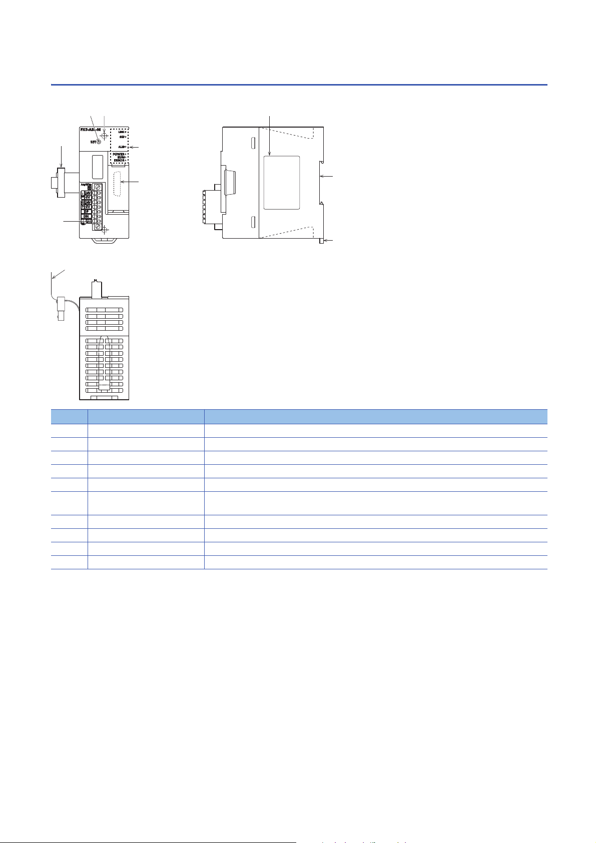
2.4 Part Names
[1]
[10]
[2]
[4][3]
[8]
[7]
[9]
[5]
[6]
This chapter describes the names of each part of the FX5-ASL-M.
No. Name Description
[1] Transmission cable terminal block A terminal block of the AnyWireASLINK
[2] Extension cable Cable for connecting the module when adding the FX5-ASL-M
[3] SET switch Switch for automatic detection of the slave module ID (address)
[4] Direct mounting hole Screw holes (2-4.5, mounting screw: M4 screw) for direct installation
[5] Operation status display LEDs Indicates the operating status of the module. (Page 19 LED display)
[6] Extension connector (for next
[7] Name plate The product model name, manufacturer's serial number etc. are shown.
[8] DIN rail mounting groove The module can be installed on DIN46277 rail (35 mm wide).
[9] DIN rail mounting hook Hook for mounting the module on a DIN rail of DIN46277 (35 mm wide).
[10] Pullout tab They are used when drawing out an extension cable.
module)
Connector for connecting the extension cable of an extension module.
18
2 SPECIFICATIONS
2.4 Part Names
Page 21

LED display
The following table lists the LED display.
LED display LED color Description
POWER Green Indicates the operating status.
On: Power on
Off: Power off or module failure
RUN Green Indicates the operating status.
On: Normal operation
Off: Error
ERROR Red Indicates the error status.
On: Minor error or major error
Flashing: Moderate error or major error
Off: Normal operation
LINK Green Indicates the link status.
Flashing: Normal operation
Off: 5 V DC power off or module failure
SET Green Indicates the address detection status.
On: Automatic address detection in progress
Flashing: Writing in the EEPROM
Off: Normal operation
ALM Red Indicates the warning status.
On: DP/DN disconnection, no response from the slave module
Flashing (1-second intervals): DP-DN short circuit, 24V-DP short circuit
Flashing (0.2-second intervals): A 24 V DC power supply is not being supplied or the voltage is low.
Off: Normal operation
2
2 SPECIFICATIONS
2.4 Part Names
19
Page 22

3 PROCEDURES BEFORE OPERATION
This chapter describes the procedures before operation.
1. Checking the specifications of the FX5-ASL-M
Check the specifications of the FX5-ASL-M. (Page 16 SPECIFICATIONS)
2. Installation of the FX5-ASL-M
Connect the FX5-ASL-M to the CPU module. For details, refer to the following.
MELSEC iQ-F FX5U User's Manual (Hardware)
MELSEC iQ-F FX5UC User's Manual (Hardware)
3. Configuring a system
Configure an AnyWireASLINK system and set parameters which are required for start-up.
• Wiring (Page 45 WIRING)
• Parameter setting (Page 51 PARAMETER SETTINGS)
• Address setting of slave modules (Page 54 Slave Module Address Setting)
• Automatic address detection function (Page 55 Automatic Address Detection Function)
4. Powering on the system
Power on and start the system in the order shown below.
• Turn on the 24 V DC external power supply for the AnyWireASLINK system.
• Turn on the power supply of the programmable controller.
5. Checking operations with the LEDs
Check whether communications are established normally.
When the communications are established normally, the following LED on/off statuses are as follows.
• POWER LED: On
• RUN LED: On
• ERROR LED: Off
• LINK LED: Flashing
• SET LED: Off
• ALM LED: Off
6. Programming
Create a program. For details, refer to the following.
Page 59 PROGRAMMING
• If the programmable controller is powered on before the 24 V DC external power supply in the
AnyWireASLINK system, a transmission cable voltage drop detection error may occur.
• To power off the system, power off the programmable controller, and turn off the 24 V DC external power
supply in the AnyWireASLINK system.
20
3 PROCEDURES BEFORE OPERATION
Page 23

MEMO
3
3 PROCEDURES BEFORE OPERATION
21
Page 24

4 FUNCTION
4.1 Function List
The following table lists the function available for the FX5-ASL-M.
AnyWireASLINK transmission
Function Description Reference
Bit transmission Exchanges I/O data of up to 384 points (input max. 256 points, output max. 256 points)
between the FX5-ASL-M and a slave module.
Double check A double check is an error control system. In this system, cycle data in AnyWireASLINK
Slave module parameter read/write In AnyWireASLINK, parameter information of a slave module and the AnyWireASLINK system
transmission is recognized as valid data if the data matches with the data of the last
transmission or is ignored as invalid data if the data does not match with the last data.
A double check ensures reliability of communication.
in addition to I/O information are sent and received between the FX5-ASL-M and a slave
module.
Execute this function to check or change parameter information of a slave module.
Address setting
Function Description Reference
Automatic address detection function Enables the FX5-ASL-M to detect and store the ID (address) of the connected slave module
when the SET switch on the FX5-ASL-M is pressed.
Remote address change function Changes an ID (address) of a slave module using the buffer memory area without an address
Same ID used detection function Checks whether the same ID is used for multiple slave modules through automatic address
Module with no ID setting detection
function
writer.
detection or same address used check. The LEDs of the relevant slave modules are forcibly
turned on.
Detects slave modules with no ID assigned (default ID) through automatic address detection
or same address used check.
Page 23
Page 24
Page 35
Page 55
Page 25
Page 26
Page 28
RAS
Function Description Reference
Transmission cable short detection
function
Disconnected transmission cable
location detection function
Transmission cable voltage drop
detection function
Protects the system by detecting the current out of the specifications of the AnyWireASLINK
system across DP-DN or 24V-DP and stopping the transmission.
Notifies the ID of a slave module that has been separated from the FX5-ASL-M because of
disconnection in the transmission cables (DP, DN) between the FX5-ASL-M and the slave
module, to locate the disconnection in the transmission cables (DP, DN) from the upper
system.
Detects a voltage drop in the 24 V DC external power supply, enabling the FX5-ASL-M to
detect a failure in the 24 V DC external power supply or a wiring error from the upper system.
Page 29
Page 30
Page 31
Others
Function Description Reference
Parameter access error detection
function
Error status automatic recovery
function
Slave information acquisition at startup function
Allows parameter access errors to be detected. Page 32
Allows for automatic error reset for DP/DN disconnection errors and parameter errors after the
error status is cleared.
Allows for automatic acquisition of information of slave modules when the CPU module is
reset or power off and on the system.
Page 34
Page 34
22
4 FUNCTION
4.1 Function List
Page 25

4.2 AnyWireASLINK Transmission
(1) (2)
(5)
M2000
M2001
M2002
M2255
M3000
M3001
M3002
M3255
(3)
ID: 200H
IN 1
IN 0
(4)
(6)
(7)
ID: 0H
OUT 1
OUT 0
U1\G0.0
U1\G0.1
U1\G0.2
U1\G15.F
U1\G4096.0
U1\G4096.1
U1\G4096.2
U1\G4111.F
The AnyWireASLINK is a high-speed and highly reliable system which releases the work site from complicated and incorrect
wiring.
In AnyWireASLINK, the FX5-ASL-M communicates with slave modules using IDs (addresses) of the slave modules.
The IDs (addresses) of the slave modules are stored in the buffer memory of the FX5-ASL-M.
4
(1) CPU module
(2) FX5-ASL-M
(3) Input slave module (ASLINKER): Address 0
(4) Output slave module (ASLINKER): Address 0
(5) Buffer memory
(6) Sensor switch
(7) LED
Bit transmission
A maximum of 384 I/O data points (input max. 256 points, output max. 256 points) can be exchanged between the FX5-ASL-
M and a slave module.
4 FUNCTION
4.2 AnyWireASLINK Transmission
23
Page 26

4.3 Double Verification
bit bit
·
bit bit
·
(1)
·
·
(4)
(2)
(3)(3)
word word
·
word word
·
(1)
·
·
(4)
(2)
(3)(3)
A double check is an error control system. In this system, cycle data in AnyWireASLINK transmission is recognized as valid
data if the data matches with the data of the last transmission or is ignored as invalid data if the data does not match with the
last data. The double verification ensures reliability of communication.
The double verification is classified into a bit double verification and word double verification.
Overview
■Bit double verification
If one bit of data is the same between two successive transmission cycles, the data is valid and I/O data is communicated.
(1) Transmission cycle (last)
(2) Transmission cycle (current)
(3) I/O data
(4) This data is compared with the verification data (one bit) of the last transmission cycle.
■Word double verification
If one word (16 bits) of data is the same between two successive transmission cycles, the data is valid and I/O data is
communicated.
(1) Transmission cycle (last)
(2) Transmission cycle (current)
(3) I/O data
(4) The data is compared with the verification data (one word) of the last transmission cycle.
The bit double verification is suitable for digital I/O type slave modules, which use information in units of bits.
The word double verification is suitable for analog I/O type slave modules, which use information in units of
words.
Setting method
Set the double verification in "Double verification" of "Basic setting". (Page 52 Double verification)
24
4 FUNCTION
4.3 Double Verification
Page 27

4.4 Remote Address Change Function
ID
0200H 0210H
With this function, an ID (address) of a slave module can be changed using the buffer memory area without an address writer.
Applicable slave module
For the slave modules that support the remote address change function, contact Anywire Corporation.
Operating procedure
1. Execute automatic address detection to check that no error has occurred in the AnyWireASLINK system. (Page 55
Automatic Address Detection Function)
2. Specify an access method to a slave module.
Store 0002H (address change) in 'Parameter access setting' (Un\G10320).
4
3. Specify an ID of the slave module to be accessed.
Store the ID to be changed (old ID) in 'Parameter access target module ID specification' (Un\G10321).
ID Description
0000H to 00FFH ID of the output slave module
0200H to 02FFH ID of the input slave module or I/O combined slave module
4. Specify a new ID of the slave module.
Store the new ID in 'Change ID specification' (Un\G10323).
ID Description
0000H to 00FFH ID of the output slave module
0200H to 02FFH ID of the input slave module or I/O combined slave module
If the specified ID has already been used or is out of the allowable specification range, an error occurs.
5. Turn on and off 'Parameter access request command for the slave module' (Un\G27 b8).
At this time, 'Parameter access completion flag' (Un\G28 b9) turns off. When the parameter access is completed, 'Parameter
access completion flag' (Un\G28 b9) automatically turns on.
6. After changing the IDs of all the target slave modules, execute automatic address detection. (Page 55 Automatic
Address Detection Function)
Precautions
• Before executing this function, make sure to execute automatic address detection to check that no error has occurred in the
AnyWireASLINK system. (Page 55 Automatic Address Detection Function)
• This function cannot be executed for slave modules separated from the FX5-ASL-M because of disconnection or slave
modules having the same ID. Use an address writer to change the IDs of such slave modules.
• This function can be executed if only one slave module having no ID exists within one AnyWireASLINK line. If IDs of
multiple slave modules are not set, it is recognized as an ID duplication. Thus, the IDs cannot be changed.
4.4 Remote Address Change Function
4 FUNCTION
25
Page 28

4.5 Same ID Used Detection Function
This function checks whether the same ID is used for multiple slave modules through automatic address detection or same
address used check. The LEDs of the relevant slave modules are forcibly turned on.
• ID duplications are detected through automatic address detection or same address used check. If the CPU
module is reset or the power is turned off after ID duplication detection, the same ID used status cannot be
checked until automatic address detection or same address used check is executed again.
• Even if an ID is assigned to multiple modules, a single ID is stored in 'Number of the alarm IDs' (Un\G9984)
and 'Alarm ID information storage area' (Un\G9985 to Un\G10112). For example, even when multiple
modules have an ID 10, "1" is stored in 'Number of the alarm IDs' (Un\G9984) and "10" is stored in 'Alarm ID
information storage area' (Un\G9985 to Un\G10112).
How to execute automatic address detection
For details on automatic address detection, refer to the following.
Page 55 Automatic Address Detection Function
How to execute same address used check
Turn off and on 'Overlap address inspection command' (Un\G27 b2). If 'Overlap address inspection flag' (Un\G28 b12) turns
on and off, it indicates that the same address used check is completed.
The same address used check cannot be executed under any of the following conditions.
• When an error occurs in the AnyWireASLINK system (Example: Short circuit, 24 V DC external power supply voltage drop)
• Within approximately five seconds after the AnyWireASLINK system is powered on or system is reset
• When automatic address detection is in progress (While 'Automatic address detection flag' (Un\G28 b11) is on)
• When the same address used check is in progress (While 'Overlap address inspection flag' (Un\G28 b12) is on)
• When the parameter access is in progress (While 'Parameter access request command for the slave module' (Un\G27 b8),
'Parameter batch read command for the slave module' (Un\G27 b9), or 'Parameter batch write command for the slave
module' (Un\G27 b10) is on)
• When any of the following errors has occurred
Error code Error description
0CC8H Transmission cable voltage drop error
0CC9H DP/DN short error
0CCBH 24V/DP short error
1867H FX5-ASL-M hardware failure
3064H
3065H
3066H
How to check the same ID used status
When the AnyWireASLINK system is in the following status, the same ID is used for multiple modules.
Even in the same ID used status, the AnyWireASLINK bit transmission does not stop.
• 'Slave module alarm signal' (Un\G28 b8) turns on.
• Same ID used error (error code: 0D90H) is stored in 'Latest error code storage area' (Un\G10256) and the duplicate ID is
stored in 'Latest error ID storage area' (Un\G10257).
• The relevant ID is stored in 'Alarm ID information storage area' (Un\G9985 to Un\G10112).
*1 If multiple errors occur simultaneously, the latest error is displayed.
26
4 FUNCTION
4.5 Same ID Used Detection Function
*1
Page 29

How to recover from same ID used status
Check 'Number of the alarm IDs' (Un\G9984) and 'Alarm ID information storage area' (Un\G9985 to Un\G10112). Then set a
unique ID (address) in all the slave modules. (Page 78 Number of the alarm IDs, Page 78 Alarm ID information storage
area)
Set IDs (addresses) of slave modules and execute automatic address detection of the FX5-ASL-M. Then, the IDs of the slave
modules are stored in the FX5-ASL-M and the error is cleared. (Page 55 Automatic Address Detection Function)
Precautions
While an ID (address) is used for multiple slave modules, executing either of the following can eliminate the same ID used
error. However, the address is still used for the multiple slave modules.
• Powering off and on the AnyWireASLINK system
• Turning off and on 'Error flag clear command' (Un\G27 b0)
4
4 FUNCTION
4.5 Same ID Used Detection Function
27
Page 30

4.6 Module with No ID Setting Detection Function
This function detects slave modules with no ID assigned (default ID) through automatic address detection or same address
used check.
Module Default ID
Input slave module, I/O combined slave module 767
Output slave module 255
• Modules with no ID set are detected through automatic address detection or same address used check. If
the CPU module is reset or the power is turned off after a module with no ID set is detected, the no ID
number setting status cannot be checked until automatic address detection or same address used check is
executed again.
• Even if no ID is assigned to modules, a single ID is stored in 'Number of the alarm IDs' (Un\G9984) and
'Alarm ID information storage area' (Un\G9985 to Un\G10112). For example, even when multiple modules
have an ID 255, "1" is stored in 'Number of the alarm IDs' (Un\G9984) and "255" is stored in 'Alarm ID
information storage area' (Un\G9985 to Un\G10112).
How to execute automatic address detection
For details on automatic address detection, refer to the following.
Page 55 Automatic Address Detection Function
How to execute same address used check
Turn off and on 'Overlap address inspection command' (Un\G27 b2). If 'Overlap address inspection flag' (Un\G28 b12) turns
on and off, it indicates that the same address used check is completed.
The same address used check cannot be executed under any of the following conditions.
• When an error occurs in the AnyWireASLINK system (Example: Short circuit, 24 V DC external power supply voltage drop)
• Within approximately five seconds after the AnyWireASLINK system is powered on or system is reset
• When automatic address detection is in progress (While 'Automatic address detection flag' (Un\G28 b11) is on)
• When the same address used check is in progress (While 'Overlap address inspection flag' (Un\G28 b12) is on)
• When the parameter access is in progress (While 'Parameter access request command for the slave module' (Un\G27 b8),
'Parameter batch read command for the slave module' (Un\G27 b9), or 'Parameter batch write command for the slave
module' (Un\G27 b10) is on)
• When any of the following errors has occurred
Error code Error description
0CC8H Transmission cable voltage drop error
0CC9H DP/DN short error
0CCBH 24V/DP short error
1867H FX5-ASL-M hardware failure
3064H
3065H
3066H
28
4 FUNCTION
4.6 Module with No ID Setting Detection Function
Page 31

How to check the no ID number setting status
When the AnyWireASLINK system is in the following status, no ID number setting status is detected.
Even in the no ID number setting status, the AnyWireASLINK bit transmission does not stop.
• 'Slave module alarm signal' (Un\G28 b8) turns on.
• No ID setting error (error code: 0D91H) is stored in 'Latest error code storage area' (Un\G10256) and unset ID is stored in
'Latest error ID storage area' (Un\G10257).
• Unset IDs are stored in 'Alarm ID information storage area' (Un\G9985 to Un\G10112).
*1 If multiple errors occur simultaneously, the latest error is displayed.
*1
How to recover from the no ID number setting status
Check 'Number of the alarm IDs' (Un\G9984) and 'Alarm ID information storage area' (Un\G9985 to Un\G10112). Then set
addresses to slave modules. (Page 78 Number of the alarm IDs, Page 78 Alarm ID information storage area)
Check that "255" is not set as the address of the slave module.
Set IDs (addresses) of slave modules and execute automatic address detection of the FX5-ASL-M. Then, the IDs of the slave
modules are stored in the FX5-ASL-M and the error is cleared. (Page 55 Automatic Address Detection Function)
Precautions
While an ID (address) of a slave module is not set, executing either of the following can eliminate the no ID setting error.
However the address of the slave module is still not set.
• Powering off and on the AnyWireASLINK system
• Turning off and on 'Error flag clear command' (Un\G27 b0)
4
4.7 Transmission Cable Short Detection Function
This function protects the system by detecting the current out of the specifications of the AnyWireASLINK system across DP-
DN or 24V-DP and stopping the transmission.
How to check the transmission cable short status
When the AnyWireASLINK system is in the following status, a transmission cable short has occurred.
• The LINK LED turns off and the ALM LED flashes repeatedly at one second intervals.
• When any of the transmission cables (DP, DN) is short-circuited, 'DP/DN short error' (Un\G28 b1) turns on.
• When any of the transmission cables (24V, DP) is short-circuited, '24V/DP short error' (Un\G28 b2) turns on.
• A DP/DN short error (error code: 0CC9H) or 24V/DP short error (error code: 0CCBH) is stored in 'Latest error code storage
area' (Un\G10256) and 0FFFH is stored in 'Latest error ID storage area' (Un\G10257).
• The AnyWireASLINK bit transmission stops.
*1 If multiple errors occur simultaneously, the latest error is displayed.
How to recover from the transmission cable short status
How to recover from the transmission cable short status is as follows.
1. Eliminate the short circuit in the AnyWireASLINK system.
When the short status is exited, AnyWireASLINK bit transmission resumes automatically.
If the status does not change, the short circuit has not been eliminated. Check it again.
2. Power off and on the AnyWireASLINK system or turn on and off 'Error flag clear command' (Un\G27 b0).
The following status is resulted:
• 'DP/DN short error' (Un\G28 b1) and '24V/DP short error' (Un\G28 b2) turn off.
• The ALM LED turns off.
• The data in 'Latest error code storage area' (Un\G10256) and 'Latest error ID storage area' (Un\G10257) are cleared.
*1
*1
4 FUNCTION
4.7 Transmission Cable Short Detection Function
29
Page 32

4.8 Disconnected Transmission Cable Location
Detection Function
This function notifies the ID of a slave module that has been separated from the FX5-ASL-M because of disconnection in the
transmission cables (DP, DN) between the FX5-ASL-M and the slave module, to locate the disconnection in the transmission
cables (DP, DN) from the upper system.
• To enable the disconnected transmission cable location detection function, execute automatic address
detection when configuring, modifying, or expanding the system. (Page 55 Automatic Address
Detection Function)
• After a system is configured, the disconnection detection may still work when a slave module is
disconnected from the system. Execute automatic address detection after modifying the system.
• Even if disconnection in the transmission cable (DP, DN) is detected, the AnyWireASLINK bit transmission
does not stop.
How to check the transmission cable disconnection status
When the AnyWireASLINK system is in the following status, the transmission cable (DP, DN) have been disconnected or a
slave module error has occurred.
• The ALM LED turns on.
• 'DP/DN disconnection error' (Un\G28 b4) turns on.
• The number of error IDs is stored in 'Number of the error IDs' (Un\G8192).
• The disconnected ID (address) is stored in 'Error ID information storage area' (Un\G8193 to Un\G8320).
• The bits of 'Error ID information bit area (output)' (Un\G8704 to Un\G8719) and 'Error ID information bit area (input)'
(Un\G8736 to Un\G8751) corresponding to the disconnected ID (address) turn on.
• DP/DN disconnection error (error code: 0CCAH) is stored in 'Latest error code storage area' (Un\G10256) and the
disconnected ID is stored in 'Latest error ID storage area' (Un\G10257).
*1 If multiple errors occur simultaneously, the latest error is displayed.
*1
*1
How to recover from the transmission cable disconnection status
How to recover from the transmission cable disconnection status is as follows.
1. Eliminate the disconnection in the AnyWireASLINK system.
When the disconnection status is exited, AnyWireASLINK bit transmission resumes automatically.
When the slave module has been disconnected from the system, execute automatic address detection. (Page 55
Automatic Address Detection Function)
2. Power off and on the AnyWireASLINK system or turn on and off 'Error flag clear command' (Un\G27 b0).
The following status is resulted:
• 'DP/DN disconnection error' (Un\G28 b4) turns off.
• The ALM LED turns off.
• The data in 'Latest error code storage area' (Un\G10256) and 'Latest error ID storage area' (Un\G10257) are cleared.
• When the automatic address detection is executed in step 1, the operation in step 2 is not necessary.
• If the error status automatic recovery mode is set in "Error status automatic recovery" of "Basic setting", the
error status is automatically cleared after the disconnection status is exited.
30
4 FUNCTION
4.8 Disconnected Transmission Cable Location Detection Function
Page 33

4.9 Transmission Cable Voltage Drop Detection
Function
This function detects a voltage drop in the 24 V DC external power supply, enabling the FX5-ASL-M to detect a failure in the
24 V DC external power supply or a wiring error from the upper system.
For the specifications of the 24 V DC external power supply to the FX5-ASL-M, refer to the Page 16
Power Supply Specifications.
How to check the transmission cable voltage drop status
When the AnyWireASLINK system is in the following status, a voltage drop in the 24 V DC external power supply has been
detected.
• The ALM LED flashes at 0.2 second intervals.
• 'Transmission cable voltage drop error' (Un\G28 b3) turns on.
• Transmission cable voltage drop error (error code: 0CC8H) is stored in 'Latest error code storage area' (Un\G10256) and
0FFFH is stored in 'Latest error ID storage area' (Un\G10257).
• The AnyWireASLINK bit transmission stops.
*1 If multiple errors occur simultaneously, the latest error is displayed.
*1
*1
How to recover from the transmission cable voltage drop status
How to recover from the transmission cable voltage drop status is as follows.
1. Check the voltage of the 24 V DC external power supply and replace the power supply or check the wiring, as necessary.
When the transmission cable voltage drop is corrected, AnyWireASLINK bit transmission resumes automatically.
2. Power off and on the AnyWireASLINK system or turn on and off 'Error flag clear command' (Un\G27 b0).
The following status is resulted:
• 'Transmission cable voltage drop error' (Un\G28 b3) turns off.
• The ALM LED turns off.
• The data in 'Latest error code storage area' (Un\G10256) and 'Latest error ID storage area' (Un\G10257) are cleared.
4
4 FUNCTION
4.9 Transmission Cable Voltage Drop Detection Function
31
Page 34

4.10 Parameter Access Error Detection Function
This function allows parameter access errors to be detected.
• Slave module hardware error (error code: 0D2CH, 0D2DH)
• Parameter access target module ID error (error code: 0D2EH)
• Parameter value error (error code: 0D2FH)
• Parameter access error (error code: 0D30H)
• Slave module status error (error code: 0D31H)
• Same ID used error (error code: 0D90H)
• No ID setting error (error code: 0D91H)
• New ID error (error code: 0D92H)
How to check the parameter access error status
The following table lists parameter access error statuses.
Error description Status when an error occurred
Status information Buffer memory
Slave module hardware error 'Slave module alarm signal' (Un\G28 b8) turns on. ■'Latest error code storage area' (Un\G10256)
Parameter access target module ID
error
Parameter value error
Parameter access error 'Parameter access error' (Un\G28 b10) turns on.
Slave module status error 'Slave module alarm signal' (Un\G28 b8) turns on.
Same ID used error
No ID setting error
New ID error
The error code is stored.
■'Latest error ID storage area' (Un\G10257)
The IDs corresponding to the error codes are stored.
■'Number of the alarm IDs' (Un\G9984)
The number of IDs relevant to alarm occurrence is stored.
■'Alarm ID information storage area' (Un\G9985 to
Un\G10112)
The IDs relevant to alarm occurrence are stored.
*2
*1
*2
*1 If multiple errors occur simultaneously, the latest error is displayed.
*2 If an error occurs in parameter access, data are stored in 'Number of the error IDs' (Un\G8192) and 'Error ID information storage area
(Un\G8193 to Un\G8320)'.
How to recover from the parameter access error status
How to recover from the parameter access error status is as follows.
■Slave module hardware error
Take measures such as those against noise to remove factors causing errors. Then power off and on the AnyWireASLINK
system or turn on and off 'Error flag clear command' (Un\G27 b0).
■Parameter access target module ID error, parameter value error
Remove factors causing errors (for example, parameter access program). Then power off and on the AnyWireASLINK system
or turn on and off 'Error flag clear command' (Un\G27 b0).
32
4 FUNCTION
4.10 Parameter Access Error Detection Function
Page 35

■Parameter access error
If any of the following errors has occurred, eliminate the error cause.
• Slave module hardware error (error code: 0D2CH, 0D2DH)
• Slave module status error (error code: 0D31H)
• Same ID used error (error code: 0D90H)
When an error occurs in a parameter access due to a cause other than the above errors, the possible cause is noise. Take
measures such as those against noise to remove factors causing errors. Then power off and on the AnyWireASLINK system
or turn on and off 'Error flag clear command' (Un\G27 b0).
If the error status automatic recovery mode is set in "Error status automatic recovery" of "Basic setting", the
error is automatically cleared after recovery from the parameter access error status.
■Slave module status error
Check the status details of the target slave module to remove factors causing errors. Then power off and on the
AnyWireASLINK system or turn on and off 'Error flag clear command' (Un\G27 b0).
The status details of the slave module can be checked with the AnyWireASLINK parameter in 'Parameter storage area'
(Un\G12288 to Un\G12335).
*1 Buffer memory addresses when one slave module is connected. For details, refer to the following.
Page 82 Parameter storage area
*1
■Same ID used error, no ID setting error
Remove factors causing errors (for example, one ID is assigned to multiple modules or a module has no ID). Then power off
and on the AnyWireASLINK system or turn on and off 'Error flag clear command' (Un\G27 b0).
4
■New ID error
Check 'Connected module ID information storage area' (Un\G9217 to Un\G9344) and set a new ID. Then power off and on the
AnyWireASLINK system or turn on and off 'Error flag clear command' (Un\G27 b0).
Status after recovery
After recovery from parameter access error status, the following status is resulted:
Error description Signal status
Slave module hardware error • 'Slave module alarm signal' (Un\G28 b8) turns off.
Parameter access target module ID error
Parameter value error
Slave module status error
Same ID used error
No ID setting error
New ID error
Parameter access error • 'Parameter access error' (Un\G28 b10) turns off.
• The data in 'Latest error code storage area' (Un\G10256) is cleared.
• The data in 'Latest error ID storage area' (Un\G10257) is cleared.
• The data in 'Number of the alarm IDs' (Un\G9984) is cleared.
• The data in 'Alarm ID information storage area' (Un\G9985 to Un\G10112) is cleared.
• The data in 'Latest error code storage area' (Un\G10256) is cleared.
• The data in 'Latest error ID storage area' (Un\G10257) is cleared.
• The data in 'Number of the error IDs' (Un\G8192) is cleared.
• The data in 'Error ID information storage area' (Un\G8193 to Un\G8320) is cleared.
• The data in 'Error ID information bit area (output)' (Un\G8704 to Un\G8719) and 'Error ID information bit
area (input)' (Un\G8736 to Un\G8751) are cleared.
4 FUNCTION
4.10 Parameter Access Error Detection Function
33
Page 36

4.11 Error Status Automatic Recovery Function
This function allows for automatic error reset for DP/DN disconnection errors and parameter errors after the error status is
cleared.
(Usually, if an error has occurred, eliminate the error cause, and power off and on the AnyWireASLINK system or turn on and
off 'Error flag clear command' (Un\G27 b0).)
Error that can be automatically recovered
The following shows the errors that can be automatically recovered.
Error code Error description Status when an error occurred Status when an error is cleared
0CCAH DP/DN disconnection
error
0D30H Parameter access error • 'Parameter access error' (Un\G28 b10) turns on.
*1 The error causes must be eliminated from all the slave modules in which errors have occurred.
*2 If the errors 0CCAH and 0D30H have occurred in one slave module, the causes of both the errors must be eliminated.
• 'DP/DN disconnection error' (Un\G28 b4) turns on.
• Error ID information is registered in the buffer
memory address. (Page 30 How to check the
transmission cable disconnection status)
• Error ID information is registered in the buffer
memory address. (Page 32 How to check the
parameter access error status)
• 'DP/DN disconnection error' (Un\G28 b4) turns off.
• The error ID information registered in the buffer
memory address is cleared. (corresponding ID
*2
only)
• 'Parameter access error' (Un\G28 b10) turns off.
• The error ID information registered in the buffer
memory address is cleared. (corresponding ID
*2
only)
Setting method
Set the error status automatic recovery function in "Error status automatic recovery" of "Basic setting". (Page 52 Error
status automatic recovery)
*1
*1
4.12 Slave Information Acquisition at Start-up Function
This function allows for automatic acquisition of information of slave modules when the CPU module is reset or the power is
turned off and on.
The slave information acquisition at start-up function eliminates the needs for reading parameters from slave modules.
For the parameters of the slave module stored, refer to the following.
Page 35 Slave Module Parameter Read/Write
Setting method
Set the slave information acquisition at start-up function in "Startup operating mode" of "Basic setting". (Page 52 Startup
operating mode)
Operation at start-up
When communication of the FX5-ASL-M is normally established after the CPU module is reset or the power is turned off and
on, the parameters of all the registered slave modules are read all at once. The read parameters are then stored in the buffer
memory.
34
4 FUNCTION
4.11 Error Status Automatic Recovery Function
Page 37

4.13 Slave Module Parameter Read/Write
In AnyWireASLINK, parameter information of a slave module and the AnyWireASLINK system in addition to I/O information
are sent and received between the FX5-ASL-M and a slave module.
Use this function to check or change parameter information of a slave module.
For details on the parameter information to be communicated, refer to the following.
• Page 80 Parameter access setting
• Page 80 Parameter access target module ID specification
• Page 81 Parameter storage location memory number
• Page 82 Parameter storage area
Parameter reading and writing methods
There are four methods as follows to read or write the parameter information from or to a slave module.
Type Description
Automatic update The current status of all slave modules and the current values of the sensors are read at regular intervals.
(Setting values are excluded.)
Parameter access All the parameter values of the slave modules are read or written individually in accordance with the setting of
Parameter batch read All the parameter values of all slave modules are read out into the buffer memory of the FX5-ASL-M.
Parameter batch write Values set in the buffer memory of the FX5-ASL-M are written to all the parameter of all slave modules.
The following shows the readable/writable parameters.
: Possible, : Impossible
Parameter name Read/write Parameter read and write methods
Device parameter
AnyWireASLINK
parameter
*1 The device parameter name differs depending on the slave module to be used.
*1
Module ID Read/write
Status details Read
Sensing level Read
reading or writing and the target slave module.
Automatic
update
Read/write
Parameter access Parameter
Read Write
batch read
Parameter
batch write
4
Even when the parameter access, parameter batch read, or parameter batch write is executed, the bit
transmission speed of AnyWireASLINK is not reduced.
Automatic update
No special operation is required because data are automatically updated. To check the parameter information, refer to the
corresponding buffer memory address.
4 FUNCTION
4.13 Slave Module Parameter Read/Write
35
Page 38

Parameter access
The operating procedure for parameter access is as follows.
■To read parameters
1. Set the access method.
Store 0000H (read) in 'Parameter access setting' (Un\G10320).
2. Set the access target ID.
Store the access target ID in 'Parameter access target module ID specification' (Un\G10321).
ID Description
0000H to 00FFH ID of the output slave module
0200H to 02FFH ID of the input slave module or I/O combined slave module
3. Turn on and off 'Parameter access request command for the slave module' (Un\G27 b8).
At this time, 'Parameter access completion flag' (Un\G28 b9) turns off. When the parameter access is completed, 'Parameter
access completion flag' (Un\G28 b9) automatically turns on.
4. The read parameters are stored in the following location of each ID.
Device parameter in 'Parameter storage area' (Un\G12288 to Un\G12335)
*1 Buffer memory addresses when one slave module is connected. For details, refer to the following.
Page 82 Parameter storage area
■To write parameters
*1
1. Before writing parameters, read parameters according to the procedure of "To read parameters", or "Parameter batch
*1
read".
*1 Since all the parameters of the target slave module are updated at the time of writing parameters, all the parameters, including the
parameters of the changed part, must be set correctly.
If writing parameters is executed without reading parameters, it may cause malfunction.
2. Set the access method.
Store 0001H (write) in 'Parameter access setting' (Un\G10320).
3. Set the access target ID.
Store the access target ID in 'Parameter access target module ID specification' (Un\G10321).
ID Description
0000H to 00FFH ID of the output slave module
0200H to 02FFH ID of the input slave module or I/O combined slave module
4. Store the parameters to be written in the following location.
Device parameter read/write areas in 'Parameter storage area' (Un\G12288 to Un\G12335)
*1 Buffer memory addresses when one slave module is connected. For details, refer to the following.
Page 82 Parameter storage area
*1
5. Turn on and off 'Parameter access request command for the slave module' (Un\G27 b8).
At this time, 'Parameter access completion flag' (Un\G28 b9) turns off. When the parameter access is completed, 'Parameter
access completion flag' (Un\G28 b9) automatically turns on.
6. After writing parameters, check that the setting have been saved in the slave module by reading parameters in the slave
module according to the procedure of "To read parameters", or "Parameter batch read".
36
4 FUNCTION
4.13 Slave Module Parameter Read/Write
Page 39

Parameter batch read
The procedure for parameter batch read is as follows.
1. Turn on and off 'Parameter batch read command for the slave module' (Un\G27 b9).
At this time, 'Parameter access completion flag' (Un\G28 b9) turns off. When the parameter access is completed, 'Parameter
access completion flag' (Un\G28 b9) automatically turns on.
2. The read parameters are stored in the following location of each ID.
Device parameter in 'Parameter storage area' (Un\G12288 to Un\G12335)
*1 Buffer memory addresses when one slave module is connected. For details, refer to the following.
Page 82 Parameter storage area
*1
Parameter batch write
The operating procedure for parameter batch write is as follows.
1. Before executing parameter batch write, read parameters of all ID registered slave modules according to the procedure
of "Parameter batch read".
*1 Since all the parameters of the target slave module are updated at the time of writing parameters, all the parameters, including the
parameters of the changed part, must be set correctly.
If writing parameters is executed without reading parameters, it may cause malfunction.
*1
2. Store the parameters to be written in the following location.
Device parameter read/write areas in 'Parameter storage area' (Un\G12288 to Un\G12335)
*1 Buffer memory addresses when one slave module is connected. For details, refer to the following.
Page 82 Parameter storage area
*1
3. Turn on and off 'Parameter batch write command for the slave module' (Un\G27 b10).
At this time, 'Parameter access completion flag' (Un\G28 b9) turns off. When the parameter access is completed, 'Parameter
access completion flag' (Un\G28 b9) automatically turns on.
4. After executing parameter batch write, check that the setting have been saved in the slave module by reading
parameters in the slave module according to the procedure of "To read parameters", or "Parameter batch read".
• During the parameter access, parameter batch read, and parameter batch write, 'Parameter access
completion flag' (Un\G28 b9) is off. When 'Parameter access completion flag' (Un\G28 b9) is off, the
parameter access, parameter batch read, and parameter batch write cannot be executed.
• Upon parameter batch read or parameter batch write, the values stored in 'Parameter access setting'
(Un\G10320) and 'Parameter access target module ID specification' (Un\G10321) are ignored.
• The buffer memory areas Un\G10496 to Un\G10751 store the start address of the buffer memory area that
stores parameters of output slave modules with the IDs. The 48 words from the buffer memory start address
is the parameter information of each ID.
• The buffer memory areas Un\G11008 to Un\G11263 store the start address of the buffer memory area that
stores parameters of input slave modules or I/O combined slave modules with the IDs. The 48 words from
the buffer memory start address is the parameter information of each ID.
4
4 FUNCTION
4.13 Slave Module Parameter Read/Write
37
Page 40

Parameter access timing
ON
ON
OFF
OFF
OFF
ON
ON
OFF
(1)
(2) (4)
(5)
(6)
(7)
(3)
'Parameter access request command for the slave module' (Un\G27 b8),
'Parameter batch read command for the slave module' (Un\G27 b9),
'Parameter batch write command for the slave module' (Un\G27 b10)
'Parameter access completion flag' (Un\G28 b9)
'Parameter access error' (Un\G28 b10)
'Error flag clear command' (Un\G27 b0)
Executed in the program
Executed by the FX5-ASL-M
The parameter access timing is as follows.
No. Description
(1) Turn off and on any of the signals below with a program to start parameter access.
(2) The operation in (1) turns off 'Parameter access completion flag' (Un\G28 b9).
(3) The parameter access is in progress.
(4) When parameter access (read/write) is completed, 'Parameter access completion flag' (Un\G28 b9) automatically turns off and on.
(5) If parameter access has an error, 'Parameter access error' (Un\G28 b10) turns off and on and 'Parameter access completion flag' (Un\G28 b9)
(6) Turning off and on 'Error flag clear command' (Un\G27 b0) with a program turns on and off 'Parameter access error' (Un\G28 b10).
(7) Turn on and off the signal that has been turned off and on in the step (1) with a program.
• 'Parameter access request command for the slave module' (Un\G27 b8)
• 'Parameter batch read command for the slave module' (Un\G27 b9)
• 'Parameter batch write command for the slave module' (Un\G27 b10)
automatically turns off and on.
*2
*1 Before the start of parameter access from the FX5-ASL-M to the slave module, apply the access method, access target ID, and
parameter data to the buffer memory.
*2 Error codes are stored in 'Latest error code storage area' (Un\G10256) and the target IDs are stored in 'Latest error ID storage area'
(Un\G10257). (The latest information is overwritten.)
*1
38
4 FUNCTION
4.13 Slave Module Parameter Read/Write
Page 41

Precautions
■Parameter setting
Parameters cannot be set in the following cases.
• When an error occurs in the AnyWireASLINK system (Example: Short circuit, 24 V DC external power supply voltage drop)
• Within approximately five seconds after the AnyWireASLINK system is powered on or CPU module is reset
• When automatic address detection is in progress (While 'Automatic address detection flag' (Un\G28 b11) is on)
• When the same address used check is in progress (While 'Overlap address inspection flag' (Un\G28 b12) is on)
• When the parameter access is in progress (While 'Parameter access request command for the slave module' (Un\G27 b8),
'Parameter batch read command for the slave module' (Un\G27 b9), or 'Parameter batch write command for the slave
module' (Un\G27 b10) is on.)
• When any of the following errors has occurred
Error code Error description
0CC8H Transmission cable voltage drop error
0CC9H DP/DN short error
0CCBH 24V/DP short error
1867H FX5-ASL-M hardware failure
3064H
3065H
3066H
■Parameter reading and writing
• Since all the parameters of the target slave module are updated at the time of writing parameters, all the parameters,
including the parameters of the changed part, must be set correctly. Make sure to read parameters immediately before
writing parameters to store the latest contents of the parameters. After storing the necessary parameter values, write
parameters. If writing parameters is executed without reading parameters, it may cause malfunction.
• When parameter read or write is in progress, 'Parameter access completion flag' (Un\G28 b9) turns off. Refer to the section
describing the parameter access timing, and adjust the access timing. (Page 38 Parameter access timing)
• When parameter read or write is in progress, do not execute re-access to the parameters and automatic address detection.
Doing so can cause a malfunction of the module.
4
■Parameter access, parameter batch read, and parameter batch write
• These operations cannot be performed to a slave module whose ID has not been registered in the FX5-ASL-M.
• Remove a same ID used error or a no ID setting error of the slave module. Then perform the operations.
■Others
• When the automatic address detection is executed, the parameter batch read is executed simultaneously.
• Note that the FX5-ASL-M may communicate with a slave module and output parameters even if no parameters are set.
4 FUNCTION
4.13 Slave Module Parameter Read/Write
39
Page 42

5 SYSTEM CONFIGURATION
(1)
(2)
(3)
(4)(7) (7)
(6)
(5)
5.1 System Configuration of AnyWireASLINK
An AnyWireASLINK system consists of the FX5-ASL-M, slave modules, and a terminating unit.
The slave modules and terminating unit are products manufactured by Anywire Corporation.
(1) FX5-ASL-M
(2) Slave module (ASLINKER)
(3) Slave module (ASLINKAMP)
(4) Terminating unit
(5) Cylinder, switch, or others
(6) Sensor head
(7) Link connector
For the number of connectable slave modules, refer to the following.
Page 17 Performance Specifications
40
5 SYSTEM CONFIGURATION
5.1 System Configuration of AnyWireASLINK
Page 43

5.2 Power Supply to the AnyWireASLINK System
Method of supplying the power to the slave module
Connect a 24 V DC external power supply to the FX5-ASL-M.
The power consumed in the internal control circuits of all the slave modules and the external load power connected to nonisolation slave modules are supplied collectively from the 24 V DC external power supply connected to the FX5-ASL-M. (
Page 16 Power Supply Specifications)
Scope of the power supply with transmission cables (DP and DN)
The current consumption of the system must satisfy all the following conditions for an FX5-ASL-M.
Item Calculation formula Description
Condition 1 I(A) = (Ihin m) + (Iho n) + (Izdin p) +
(Izdo q) The maximum value of
transmission cable supply current
Condition 2 Vm(V) - V(V) 20 V Vm: Supply voltage for the FX5-ASL-M
Condition 3 Vm(V) - V(V) The lowest allowable
voltage of the connected load
Ihin: Current consumption of the non-isolation input slave module/I/O combined slave module
Iho: Current consumption of the non-isolation output slave module
Izdin: Current consumption of the isolation input slave module/I/O combined slave module
Izdo: Current consumption of the isolation output slave module
m: Number of connected non-isolation input slave modules/I/O combined slave modules
n: Number of connected non-isolation output slave modules
p: Number of connected isolation input slave modules/I/O combined slave modules
q: Number of connected isolation output slave modules
V: Cable-to-cable voltage drop
5
5 SYSTEM CONFIGURATION
5.2 Power Supply to the AnyWireASLINK System
41
Page 44

Description of condition 1
IN OUT
24V 0V
24V 0V
24V 0V
24VL
0VL 0 1 n
DP DN
DP DN
(2)
(3)
(4)
(5)
(1)
FX5-ASL-M
■Constants related to the non-isolation slave module (Ihin, Iho)
In the non-isolation slave module, the current required for the internal control circuit and the connected load is supplied with
transmission cables (DP, DN).
■Ihin(A): Current consumption of the non-isolation input slave module/I/O combined slave module
= Current consumption of the non-isolation input slave module/I/O combined slave module + Current consumption of connected load (three-wire sensor)
Number of points
■Iho(A): Current consumption of the non-isolation output slave module
= Current consumption of the non-isolation output slave module + Current consumption of connected load Number of points
(1) 24 V DC external power supply
(2) Non-isolation slave module
(3) Internal control circuit
(4) Power supply generation
(5) Connected load
• The 24VL and 0VL terminals of a slave module are used to supply the power to the connected load.
• For the current consumption of a non-isolation slave module, refer to the manual for the slave module used.
42
5 SYSTEM CONFIGURATION
5.2 Power Supply to the AnyWireASLINK System
Page 45

■Constants related to the isolation slave module (Izdin, Izdo)
24V 0V
24V
IN OUT
0V
24V 0V
24VL
0VL 0 1 n
DP DN
DP DN
(2)
(3)
(4)
(5)
(1)
FX5-ASL-M
In the isolation slave module, only the current required for the internal control circuit is supplied with the transmission cables
(DP, DN), whereas that for the connected load is supplied from the power cables (24V, 0V).
■Izdin(A): Current consumption of the isolation input slave module/I/O combined slave module
■Izdo(A): Current consumption of the isolation output slave module
5
(1) 24 V DC external power supply
(2) Isolation slave module
(3) Internal control circuit
(4) Load driving circuit (photocoupler)
(5) Connected load
• In isolation slave modules, the current consumption of the connected load is not subject to the current
restriction condition for the AnyWireASLINK system.
• For the current consumption of isolation slave modules, refer to the manual for the slave module used.
■Transmission cable supply current (I(A))
The transmission cable supply current in the AnyWireASLINK system is determined by the following formula. (Number of
connected modules: m, n, p, q)
I(A) = (Ihin m) + (Iho n) + (Izdin p) + (Izdo q)
■Maximum transmission cable supply current
For the maximum transmission cable supply current, refer to the following.
Page 16 Power Supply Specifications
5 SYSTEM CONFIGURATION
5.2 Power Supply to the AnyWireASLINK System
43
Page 46

Description of conditions 2 and 3
■Vm: Supply voltage for the FX5-ASL-M
• Voltage: 21.6 to 27.6 V DC (24 V DC -10 to +15%), ripple voltage 0.5 Vp-p or lower
• Recommended voltage: 26.4 V DC (24 V DC +10%)
■V(V): Cable-to-cable voltage drop
Calculation formula Description
V(V) = Transmission cable supply current I(A) Cable resistance R
()
■Transmission cable supply current (I(A))
Page 43 Transmission cable supply current (I(A))
■Cable resistance R ()
= Cable length (m) Conductor resistance (/m) 2
• Wire diameter 1.25 Conductor resistance 0.015 /m
• Wire diameter 0.75 Conductor resistance 0.025 /m
Calculation example
The example shows how to check whether the total length of 100 m is sufficient to configure a system in the following
conditions.
■Condition
Item Description
Non-isolation slave module (Input ASLINKER) Number of I/O points 2 points
Module current consumption 15 mA
Number of modules 24
Connected load (three-wire sensor) Three-wire sensor current
consumption
Number of sensors 2
Power supply voltage 24 V DC 10%
Transmission cable (DP, DN) Wire diameter 1.25
Supply voltage for the FX5-ASL-M Power supply voltage 24 V DC
13 mA
■Calculation result
Item Calculation formula Result
Condition 1 I(A) = (Ihin m) = I(A) The maximum transmission cable supply current
(0.015 + (0.013 2)) 24 = 0.984 A 1 A
Condition 2 Vm(V) - V(V) 20 V
24 - (0.984 100 0.015 2) = 24 - 2.95 = 21.05 V 20 V
Condition 3 Vm(V) - V(V) The lowest allowable voltage of the connected load
The lowest limit of the allowable voltage range for connected load = 24 - 24 0.1 = 21.6V
21.05 V < 21.6 V
The calculation results of the conditions 1) to 3) show that the system cannot be configured.
However, the system can be configured if the power supply for the FX5-ASL-M is changed to 24.55 V DC or higher.
Satisfied
Satisfied
Not satisfied
44
5 SYSTEM CONFIGURATION
5.2 Power Supply to the AnyWireASLINK System
Page 47

6 WIRING
DP
DN
LG
24V
IN
OUT
0V
24V
0V
This chapter describes the wiring of the FX5-ASL-M.
6.1 Terminal Block
Type of the terminal block
The following terminal block is used in the FX5-ASL-M.
Name Model Contact
Transmission cable terminal block FMC1,5/7-STF-3,81 PHOENIX CONTACT GmbH & Co. KG
Tightening torque
Tighten terminal block screws within the following tightening torque range.
Screws tightened Tightening torque range
Terminal block mounting screw 0.2 to 0.3 Nm
To connect the terminal block, a flathead screwdriver having a tipped size of 0.42.5 mm is required.
Before removing the transmission cable terminal block, check that the terminal block mounting screws on both sides are
completely loosened (removed from the socket).
Pulling with excessive force while the terminal block mounting screws on the both sides are still tightened may damage the
device.
Before tightening, check that there are no short circuits due to disconnected or frayed wires. Then tighten the terminal block
mounting screws on both sides securely.
6
Signal name of the terminal block
The following shows the signal names of the terminal block.
Terminal block Signal name Description
IN 24V Power supply terminals for driving the transmission circuit of the AnyWireASLINK system and for a slave
0V
OUT 24V Terminals for connecting isolation (4-wire) slave modules.
0V
DP AnyWireASLINK transmission signal terminals
DN
LG Connected to the neutral point of the noise filter inserted between the 24V and 0V terminals.
module.
Connect to a 24 V DC external power supply.
If the modules are connected to these terminals, supplying power for each module from the 24 V DC external
power supply is not necessary.
DP: Transmission cable (+), DN: Transmission cable (-)
Connect to the DP and DN terminals on the slave module or terminating unit.
Ground the LG terminal with the functional ground terminal (FG terminal) on the programmable controller at a
single point.
6 WIRING
6.1 Terminal Block
45
Page 48

6.2 Wiring Method
This section describes the wiring to the transmission cable terminal block of the FX5-ASL-M.
Wiring to the transmission cable terminal block
■Connecting a cable
Insert a cable with a wire ferrule into a wire insertion opening and fully push the cable. Then, pull the cable slightly to check
that it is clamped securely.
■Disconnecting a cable
Hold down the open/close button of a cable to disconnect with a flathead screwdriver. Pull out the cable with the open/close
button held down.
46
6 WIRING
6.2 Wiring Method
Page 49

6.3 Wiring Product
Applicable wires and cables
Use the following wires or cables connected to the transmission cable terminal block.
Classification Name Wire size Temperature rating
Transmission cable (DP, DN) UL-listed general-purpose 2-wire cable (VCTF, VCT) 1.25 70 or higher
0.75
UL-listed general-purpose wire 1.25
0.75
Dedicated flat cable 1.25 90
0.75
Power supply cable (24V, 0V) UL-listed general-purpose 2-wire cable (VCTF, VCT) 0.75 to 2.0 70 or higher
UL-listed general-purpose wire 0.75 to 2.0
Dedicated flat cable 1.25 90
0.75
Wire ferrule
Bare cables can be connected to the transmission cable terminal block; however, for safety reasons, it is recommended to
connect wire ferrules.
Use UL-listed wire ferrules and, for processing, use a tool recommended by their manufacturer.
Type Model Application Contact
Wire ferrule AI 0,75-10 GY Processing of a 0.75 wire PHOENIX CONTACT GmbH & Co. KG
AI 1,5-10 Processing of a 1.25 wire
6
6 WIRING
6.3 Wiring Product
47
Page 50

6.4 Wiring Precautions
DP
DN
DP
DN
DP
DN
DP
DN
Grounding
(Grounding
resistance:
100 or less)
Grounding
(Grounding
resistance:
100 or less)
0V LG24V
FX5U CPU module
24 V DC
FX5-ASL-M
IN
PLC
Other
equipment
Other
equipment
Other
equipment
PLC PLC
Shared grounding
(Good condition)
Common grounding
(Not allowed)
Independent grounding
(Best condition)
• Do not run multiple transmission cables (DP, DN) using a multicore cable.
• The voltage should not fall below the lower limit of the allowable voltage range due to voltage drop caused by the cable. If
the voltage falls below the lower limit, malfunctions may occur.
• Do not connect soldered cables directly to the terminals. Doing so may loosen the screws, resulting in a poor contact.
• In the AnyWireASLINK system, signals and power are supplied to a slave module with two transmission cables: DP and
DN. Therefore, use a stranded wire of 1.25 or larger as the main line.
• General-purpose wire, cabtyre cable and flat cable, etc. can be used.
• Use a crimping tool to connect a wire ferrule to a cable.
• Before inserting a wire ferrule, check the shapes of the wire insertion opening and wire ferrule. Then, insert the terminal in
the correct orientation. A wire ferrule wider than the wire insertion opening may damage the terminal block. (Page 47
Wire ferrule)
• Signal names are not printed on the transmission cable terminal block. To avoid incorrect wiring, wire cables to the terminal
block attached to the FX5-ASL-M.
• Do not insert multiple wire ferrules into one wire insertion opening. Doing so may cause damage on the terminal block or
cable, or malfunction.
6.5 Power Supply/grounding Wiring
Power supply/grounding wiring
Grounding
Perform the following.
• Perform class D grounding. (Grounding resistance: 100 or less)
• Ground the PLC independently if possible.
• If the PLC cannot be grounded independently, perform the "Shared grounding" shown below.
• Bring the grounding point close to the PLC as much as possible so that the ground cable can be shortened.
48
6 WIRING
6.4 Wiring Precautions
Page 51

6.6 Connecting Slave Module or Terminating Unit
A
B
(1)
C
(2)
Connection type
• The maximum transmission distance in an AnyWireASLINK stand-alone system is 200 m, which is the overall cable
distance including the main line and branch line. (It varies depending on the wire diameter of the transmission cables (DP,
DN) or the transmission cable supply current.)
• AnyWireASLINK systems support tree branch connection, T-branch connection, and multidrop connection.
• Up to 128 slave modules can be connected.
6
(1) Tree branch connection
(2) T-branch connection
The total length of the transmission distance for the AnyWireASLINK system can be calculated from A + B +
C.
Note that the total length should not exceed the maximum transmission distance or the total length set for the
system to branch lines.
6 WIRING
6.6 Connecting Slave Module or Terminating Unit
49
Page 52

Terminating unit
(1)
(2)
To ensure more stable transmission quality, connect a terminating unit to the end of a transmission cable (DP, DN).
■Terminating unit connection
Connect at least one terminating unit for one AnyWireASLINK line. Connect it at the farthest end from the FX5-ASL-M.
■Branch of transmission cables (DP, DN)
Connect one terminating unit at the end of a branch line that exceeds 40m.
(1) Main line
(2) 40 m or longer branch line
50
6 WIRING
6.6 Connecting Slave Module or Terminating Unit
Page 53

7 PARAMETER SETTINGS
This chapter describes the parameter setting required for the FX5-ASL-M.
7.1 Parameter Setting Procedure
1. Add the FX5-ASL-M to GX Works3.
[Navigation window] [Parameter] [Module Information] Right click [Add New Module]
2. The parameter setting includes a basic setting and refresh setting. Select the settings in the tree and set the items in the
following window.
[Navigation window] [Parameter] [Module Information] [FX5-ASL-M] [Module Parameter]
3. Write the setting to the CPU module with GX Works3.
[Online] [Write to PLC]
4. Reset the CPU module or power off and on the system to apply the setting.
7.2 Basic Setting
Set the number of transmission points of the FX5-ASL-M and others.
7
7 PARAMETER SETTINGS
7.1 Parameter Setting Procedure
51
Page 54

Transmission points
Set the number of transmission points of AnyWireASLINK.
Item Description Setting range
Transmission points setting (IN) Set the number of input transmission points.
One transmission cycle time is determined by setting the number
of transmission points. (Page 85 Transmission cycle time)
Transmission points setting (OUT) Set the number of output transmission points.
One transmission cycle time is determined by setting the number
of transmission points. (Page 85 Transmission cycle time)
• 0 input points
• 8 input points
• 16 input points
• 24 input points
• 32 input points
• 48 input points
• 64 input points
• 80 input points
• 96 input points
• 128 input points
• 160 input points
• 192 input points
• 224 input points
• 256 input points
(Default: 256 input points)
• 0 output points
• 8 output points
• 16 output points
• 24 output points
• 32 output points
• 48 output points
• 64 output points
• 80 output points
• 96 output points
• 128 output points
• 160 output points
• 192 output points
• 224 output points
• 256 output points
(Default: 128 output points)
Startup operating mode
Set whether to read the parameters of slave modules at start-up of the FX5-ASL-M.
Item Description Setting range
Startup operating mode setting Set the operation mode at start-up. (Page 34 Slave
Information Acquisition at Start-up Function)
• Without slave information acquisition
• Get slave information acquisition
(Default: Without slave information acquisition)
Double verification
Set the double verification of the FX5-ASL-M.
Item Description Setting range
Double verification mode setting Set the double verification mode. (Page 24 Double
Verification)
*1 The word double verification be selected from until 1st word up to until 15th word.
• All points, double verification of bit
• Double verification of word (16 bit), until 1st word
• All points, double verification of word (16 bit)
(Default: All points, double verification of bit)
Error status automatic recovery
Set whether to automatically recover the FX5-ASL-M from the error status.
Item Description Setting range
Error status automatic recovery
mode setting
Set the error status automatic recovery mode. (Page 34 Error
Status Automatic Recovery Function)
• No error status automatic recovery
• Error status automatic recovery
(Default: No error status automatic recovery)
*1
52
7 PARAMETER SETTINGS
7.2 Basic Setting
Page 55

7.3 Refresh Setting
Setting method
Set buffer memory areas of the FX5-ASL-M to refresh.
This refresh setting eliminates the needs for reading or writing with a program.
1. Start a module parameter.
[Navigation window] [Parameter] [Module Information] [FX5-ASL-M] [Module Parameter] [Refresh Setting]
7
2. Click "Target" and set a refresh target.
Double-click the item to set and enter a refresh target device.
If refreshing is enabled, the buffer memory areas are overwritten with the values of the refresh targets.
To change the values of the buffer memory areas to be refreshed, create a program that modifies device
values of the refresh targets.
7 PARAMETER SETTINGS
7.3 Refresh Setting
53
Page 56

7.4 Slave Module Address Setting
(1)
(2)
Setting a start number of the address assigned for data communication is required for slave modules.
An address can be written to a slave module or the address assigned to a slave module can be read through infrared
communications using an address writer (manufactured by Anywire Corporation).
For details, refer to the manual of the address writer.
Image of address read/write
(1) Address setting port
(2) Light projecting/receiving part
Address setting example
When 0 is set for the 2-point input slave module address, and 0 and 2 for the 2-point output slave module address, bits are
occupied as follows.
■Buffer memory address of the input slave module
Buffer memory address Bit No.
15 14 13 12 11 10 9 8 7 6 5 4 3 2 1 0
Un\G0 1514131211109876543210
• Areas occupied by address 0: Un\G0.0, Un\G0.1
■Buffer memory address of the output slave module
Buffer memory address Bit No.
15 14 13 12 11 10 9 8 7 6 5 4 3 2 1 0
Un\G4096 15 14 13 12 11 10 9 8 7 6 5 4 3 2 1 0
• Areas occupied by address 0: Un\G4096.0, Un\G4096.1
• Areas occupied by address 2: Un\G4096.2, Un\G4096.3
Precautions
• A slave module address is not deleted even when the power supply of a programmable controller or a 24 V DC external
power supply is turned off. The address is retained until a new address is set when a system is configured.
• In the address setting, ensure that the address occupied by the slave module does not exceed the number of transmission
points set in the FX5-ASL-M. For the operation mode setting of the FX5-ASL-M, refer to the following.
Page 52 Transmission points
• In the slave module, a value between 0 and 254 can be written. (This value is not an ID.) Note that 255 cannot be set.
Doing so will cause a No ID setting error.
Model Address ID
Output slave module 0 to 254 0 to 254 (0000H to 00FEH)
Input slave module or I/O combined slave module 0 to 254 512 to 766 (0200H to 02FEH)
54
7 PARAMETER SETTINGS
7.4 Slave Module Address Setting
Page 57

7.5 Automatic Address Detection Function
Automatic address detection refers to a function that stores the IDs (addresses) of the connected slave modules in the
EEPROM of the FX5-ASL-M.
Pressing the SET switch on the FX5-ASL-M enables this function and enables the FX5-ASL-M to detect and store IDs
(addresses) of connected slave modules.
The ID (address) information stored in the EEPROM is held even when the power is turned off. However, information about
unset IDs, the same IDs, and the parameter information of each slave module are not held.
Whenever starting the system or changing the system configuration, set the correct addresses to all the slave modules and
execute the automatic address detection.
Executing the automatic address detection
To execute the automatic address detection, use the SET switch or 'Automatic address detection command' (Un/G27 b1).
Using the SET switch
1. Check that all of the slave modules are operating normally.
2. Keep pressing the SET switch on the FX5-ASL-M until the SET LED turns on.
At this time, 'Automatic address detection flag' (Un\G28 b11) turns on.
3. When the SET LED flashes for a while and turns off, the ID (address) has been stored.
4. When 'Automatic address detection flag' (Un\G28 b11) turns off, the automatic address detection is completed.
7
Using 'Automatic address detection command' (Un\G27 b1)
1. Check that all of the slave modules are operating normally.
2. Turn on and off 'Automatic address detection command' (Un\G27 b1).
At this time, 'Automatic address detection flag' (Un\G28 b11) turns on.
3. When the SET LED flashes for a while and turns off, the ID (address) has been stored.
4. When 'Automatic address detection flag' (Un\G28 b11) turns off, the automatic address detection is completed.
7 PARAMETER SETTINGS
7.5 Automatic Address Detection Function
55
Page 58

Precautions
■Situations in which automatic address detection cannot be executed
Automatic address detection cannot be executed in the following cases.
• When an error occurs in the AnyWireASLINK system (Example: Short circuit, 24 V DC external power supply voltage drop)
• Within approximately five seconds after the AnyWireASLINK system is powered on or CPU module reset recovery
• When automatic address detection is in progress (While 'Automatic address detection flag' (Un\G28 b11) is on)
• When the same address used check is in progress (While 'Overlap address inspection flag' (Un\G28 b12) is on)
• When the parameter access is in progress (While 'Parameter access request command for the slave module' (Un\G27 b8),
'Parameter batch read command for the slave module' (Un\G27 b9), or 'Parameter batch write command for the slave
module' (Un\G27 b10) is on)
• When any of the following errors has occurred
Error code Error description
0CC8H Transmission cable voltage drop error
0CC9H DP/DN short error
0CCBH 24V/DP short error
1867H FX5-ASL-M hardware failure
3064H
3065H
3066H
■Situations in which automatic address detection is required
Execute automatic address detection in the following cases.
• When starting the system operation (when all of the slave modules are connected and operating normally)
• When adding a slave module after starting the system operation
• When removing a slave module after starting the system operation
• When changing the address of a slave module after starting the system operation
■Check after execution of automatic address detection
After executing automatic address detection, check that there is no inconsistency between the actual system configuration
and the IDs registered in the FX5-ASL-M, referring to the value stored in 'Number of the IDs of the connected modules'
(Un\G9216) and values stored in 'Connected module ID information storage area' (Un\G9217 to Un\G9344).
■Executing automatic address detection again
Use an address writer to set the ID (address) in a slave module that has the same ID as other slave modules or where an ID
is not set. Then execute automatic address detection again.
■When non-processing is executed even after automatic address detection is executed
Do not execute automatic address detection in any of the following cases. Automatic address detection is not processed if
executed.
• When 'Parameter access completion flag' (Un\G28 b9) is off
• When 'Automatic address detection flag' (Un\G28 b11) is on
Create an interlock program to ensure proper execution of automatic address detection.
For the interlock program of automatic address detection, refer to the following.
Page 59 Interlock program of automatic address detection
56
7 PARAMETER SETTINGS
7.5 Automatic Address Detection Function
Page 59

Automatic address detection execution timing
ON
ON
OFF
ON
OFF
OFF
OFF
ON
ON
OFF
SET LED
Turning on 'Automatic address detection command' (Un\G27 b1)
*1
(or long press of the SET switch)
'Automatic address detection flag' (Un\G28 b11)
'Overlap address inspection flag' (Un\G28 b12)
'Parameter access completion flag' (Un\G28 b9)
'Parameter access error' (Un\G28 b10)
Automatic address detection
being executed
Address being
written
Batch read
executed
In process
The LED onThe LED
flashing
Automatic
Automatic
Automatic
A parameter access
error has occurred.
OFF
The following shows automatic address detection execution timing.
7
*1 After turning on 'Automatic address detection command' (Un\G27 b1), check that 'Automatic address detection flag' (Un\G28 b11) is on
or check the SET LED status. Then, turn off 'Automatic address detection command' (Un\G27 b1) with a program.
7.5 Automatic Address Detection Function
7 PARAMETER SETTINGS
57
Page 60

7.6 Automatic Reading of the System Configuration
Man-hours for the parameter setting can be reduced by automatically reading the information of the slave modules connected
in the AnyWireASLINK system.
[Navigation window] [Parameter] [Module Information] [FX5-ASL-M] [AnyWireASLINK Configuration]
58
For the "AnyWireASLINK Configuration" window, refer to the following.
iQ Sensor Solution Reference Manual
7 PARAMETER SETTINGS
7.6 Automatic Reading of the System Configuration
Page 61

8 PROGRAMMING
Ex.
This chapter describes programming and start-up examples of the FX5-ASL-M.
8.1 Precautions on Programming
This section describes precautions on programming on the FX5-ASL-M.
Interlock program of automatic address detection
The interlock program described here prevents 'Automatic address detection command' (Un\G27 b1) from being turned on
during a parameter access
The following shows an interlock program in which the start module number of the FX5-ASL-M is assigned to 0001H.
*1 Indicates that 'Parameter access completion flag' (Un\G28 b9) is off or 'Automatic address detection flag' (Un\G28 b11) is on.
Interlock example
Classification Label name Description Device
Module label FX5ASLM_1.bModuleREADY_D Module READY U1\G28 b0
Label to be defined Define global labels as shown below:
*1
or during automatic address detection*1, allowing proper automatic address detection.
FX5ASLM_1.bDP_DNShortError_D DP/DN short error U1\G28 b1
FX5ASLM_1.b24V_DPShortError_D 24V/DP short error U1\G28 b2
FX5ASLM_1.bTransmissionCableVoltageDdropError_D Transmission cable voltage drop error U1\G28 b3
FX5ASLM_1.bPalameterAccessCompletionFlag_D Parameter access completion flag U1\G28 b9
FX5ASLM_1.bAutomaticAddressDetectionFlag_D Automatic address detection flag U1\G28 b11
FX5ASLM_1.bOverlapAddressInspectionFlag_D Overlap address inspection flag U1\G28 b12
FX5ASLM_1.bAutomaticAdrressDetectionCommand_D Automatic address detection command U1\G27 b1
8
8 PROGRAMMING
8.1 Precautions on Programming
59
Page 62

8.2 Communication of FX5-ASL-M with Slave Module
(2)(1)(1)
(3)
(4)
(5)
(6)
(1) (2)
(5)
M2000
M2001
M2002
M2255
M3000
M3001
M3002
M3255
(3)
ID: 200H
IN 1
IN 0
(4)
(6)
(7)
ID: 0H
OUT 1
OUT 0
U0\G0.0
U0\G0.1
U0\G0.2
U0\G15.F
U0\G4096.0
U0\G4096.1
U0\G4096.2
U0\G4111.F
The input signals of the input ASLINKER, stored in 'Input information area' (Un\G0 to Un\G15) of the FX5-ASL-M, are batch-
transferred to the device data of the CPU module.
Moreover, the device data of the CPU module is batch-transferred to 'Output information area' (Un\G4096 to Un\G4111) of the
FX5-ASL-M, and the output signals are transmitted to the output ASLINKER.
System configuration example
System configuration
The following system configuration is used to explain communication between the FX5-ASL-M and slave modules.
• CPU module: FX5U CPU module
• AnyWireASLINK system master module: FX5-ASL-M (Module number: 1H)
(1) Link connector
(2) Terminating unit
(3) 2-point output ASLINKER
(4) 2-point input ASLINKER
(5) LED
(6) Sensor switch
Correlations between devices
The following shows the correlations between devices.
60
8 PROGRAMMING
8.2 Communication of FX5-ASL-M with Slave Module
(1) CPU module
(2) FX5-ASL-M
(3) Input ASLINKER: Address 0
(4) Output ASLINKER: Address 0
(5) Buffer memory
(6) Sensor switch
(7) LED
Page 63

FX5-ASL-M setting
Connect GX Works3 to the CPU module and set parameters.
1. Set the CPU module as follows.
[Project] [New]
2. Click the [OK] button to add the module labels of the CPU module.
3. Set the FX5-ASL-M as follows.
[Navigation window] [Parameter] [Module Information] Right-click [Add New Module]
8
8 PROGRAMMING
8.2 Communication of FX5-ASL-M with Slave Module
61
Page 64

4. Click the [OK] button to add the module labels of the FX5-ASL-M.
5. Set the items in "Basic setting" as follows.
[Navigation window] [Parameter] [Module Information] [FX5-ASL-M] [Module Parameter] [Basic Settings]
6. Write the set parameters into the CPU module, and reset the CPU module or power off and on the system.
[Online] [Write to PLC]
In this example, default values were used for parameters that are not shown above.
62
8 PROGRAMMING
8.2 Communication of FX5-ASL-M with Slave Module
Page 65

Settings of the slave module
Write addresses to slave modules to register the FX5-ASL-M.
Address setting
Write addresses to slave modules with an address writer.
• Output ASLINKER: Address 0 (ID: 0000H)
• Input ASLINKER: Address 0 (ID: 0200H)
Automatic address detection
Keep pressing the SET switch on the FX5-ASL-M until the SET LED turns on.
When the SET LED flashes and then turns off, it indicates that the registration of IDs (addresses) has been completed.
Checking the system status
Check whether the FX5-ASL-M can communicate with the slave modules normally.
The following LED statuses indicate that the communication is established normally.
• LED of the FX5-ASL-M
LED Status
POWER On
RUN On
ERROR Off
LINK Flashing
SET Off
ALM Off
8
• LED of the ASLINKER
LED Status
LINK LED Flashing
Other than the LINK LED Off
8 PROGRAMMING
8.2 Communication of FX5-ASL-M with Slave Module
63
Page 66

Program example
Classification Label name Description Device
Module label FX5ASLM_1.bModuleREADY_D Module READY U1\G28 b0
FX5ASLM_1.bDP_DNShortError_D DP/DN short error U1\G28 b1
FX5ASLM_1.b24V_DPShortError_D 24V/DP short error U1\G28 b2
FX5ASLM_1.bTransmissionCableVoltageDdropError_D Transmission cable voltage drop error U1\G28 b3
FX5ASLM_1.bDP_DNDisconnectionError_D DP/DN disconnection error U1\G28 b4
FX5ASLM_1.uInputInformationArea0_15_D Input information area U1\G0
FX5ASLM_1.uOutputInformationArea0_15_D Output information area U1\G4096
Label to be defined Define the global label as follows.
(38) When 'ProgramStart' (M1) is turned on, the values of 'Input information area' (U1\G0) are transferred to 'Input ASLINKER data storage area'
(K4M1000).
The values of 'OutputArea' (K4M2000) are transferred to 'Output information area' (U1\G4096).
After 'Module READY' (U1\G28 b0) turns on, wait at least one second and start the program.
64
8 PROGRAMMING
8.2 Communication of FX5-ASL-M with Slave Module
Page 67

9 TROUBLESHOOTING
This chapter describes troubleshooting of the FX5-ASL-M.
9.1 Checking with LED
This section describes troubleshooting using LED.
When the POWER LED turns off
When the POWER LED turns off after powering on the FX5-ASL-M, check the following.
Check item Action
Is the FX5-ASL-M mounted correctly? Securely mount the FX5-ASL-M on the CPU module.
When the RUN LED turns off
When the RUN LED turns off after powering on the FX5-ASL-M, check the following.
Check item Action
Is the FX5-ASL-M mounted correctly? Securely mount the FX5-ASL-M on the CPU module.
When the ERROR LED turns on
When the ERROR LED turns on, check the following.
Check item Action
Does a programmable controller error occur in the GX Works3? Confirm the details of the 'Latest error code storage area' (Un\G10256) with
the GX Works3 buffer memory monitor, and process accordingly.
9
When the LINK LED turns on or off
When the LINK LED turns on or off, check the following.
Check item Action
Does a programmable controller error occur in the GX Works3? Confirm the details of the 'Latest error code storage area' (Un\G10256) with
the GX Works3 buffer memory monitor, and process accordingly.
When the ALM LED is flashing at 0.2 second intervals
When the ALM LED is flashing at 0.2 second intervals, check the following.
Check item Action
Is the power supply voltage of the 24 V DC external power supply within the
rated value?
Is any power cable short-circuited? • Check that the power cables (24V, 0V) are not disconnected or short-
Is the terminal block properly wired? • Check that the 24 V DC external power supply is properly connected to the
Adjust the power supply voltage of the 24 V DC external power supply within
the rated value (21.6 to 27.6 V DC). (The recommended voltage is 26.4 V
DC.)
circuited.
• When crimping the link connector, check that the pin layout is correct.
terminal blocks of the FX5-ASL-M and the slave module.
• Check that there is no short circuit or incorrect wiring and screws are
tightened sufficiently.
9 TROUBLESHOOTING
9.1 Checking with LED
65
Page 68

When the ALM LED is flashing at 1 second intervals
When the ALM LED is flashing at 1 second intervals, check the following.
Check item Action
Is any transmission cable (between DP and DN, between 24V and DP, or
between 0V and DP) short-circuited?
Is the terminal block properly wired? Check that the transmission cables (DP, DN) are not in contact with each other
Is the current consumption of the AnyWireASLINK system within the specified
range?
• Check that the transmission cables (between DP and DN, between 24V and
DP, or between 0V and DP) are not short-circuited.
• When crimping the link connector, check that the pin layout is correct.
and that there is no incorrect wiring in the terminal block wiring of the FX5ASL-M and the slave module.
Correct the cables (wire diameter, total length) and modules (type, the number
of connected modules) so that the current consumption of all the slave
modules does not exceed the transmission cable supply current of the FX5ASL-M. (Page 16 Power Supply Specifications)
When the ALM LED is on
When the ALM LED is on, check the following.
Check item Action
Is any transmission cable (DP, DN) disconnected? • Check that the transmission cables (DP, DN) are free from disconnection.
Is the terminal block properly wired? • Check that the transmission cables (DP, DN) and power cables (24V, 0V)
Has the automatic address detection been executed? When creating a new system, adding or removing a slave module, or
Does the slave module exist? When the LINK LED of the slave module does not flash, check that there is no
• Check that the cables are crimped with proper pin layout using link
connectors appropriate to the wire diameter.
are properly connected to the terminal block of the FX5-ASL-M.
• Check that there is no incorrect wiring and that screws are tightened
sufficiently.
changing the address of the slave module, execute the automatic address
detection. (Page 55 Automatic Address Detection Function)
After executing the automatic address detection function, check that the
number of slave modules and the address are consistent with those of the
actual system.
disconnection, short circuit, incorrect wiring, or poor contact in the
transmission cables (DP, DN) around the module.
When the SET LED is flashing and does not turn off
When the SET LED is flashing and does not turn off, check the following.
Check item Action
Is 'Parameter access completion flag' (Un\G28 b9) off or is 'Automatic address
detection flag' (Un\G28 b11) on?
• Reset the CPU module or power off and on the system.
• Check that automatic address detection is not executed while parameter
access is in progress.
66
9 TROUBLESHOOTING
9.1 Checking with LED
Page 69

9.2 Checking Module Status
Checking with the buffer memory
The following shows the check method with the buffer memory.
Check method
[Online] [Monitor] [Device/Buffer Memory Batch Monitor]
9
Check item
For details on the buffer memory, refer to the following.
Page 74 Buffer Memory
■Check of the error details
The error code of the FX5-ASL-M is stored in 'Latest error code storage area' (Un\G10256).
■Check of the error ID area
The number of error IDs is stored in 'Number of the error IDs' (Un\G8192) and the ID information is stored in 'Error ID
information storage area' (Un\G8193 to Un\G8320).
■Check of the alarm signal area
The number of slave modules having an error is stored in 'Number of the alarm IDs' (Un\G9984) and the ID information is
stored in 'Alarm ID information storage area' (Un\G9985 to Un\G10112).
■Check of the error details of the slave module
The details of errors in the slave module are stored in the status details in 'Parameter storage area' (Un\G12288 to
Un\G12335).
*1 Buffer memory addresses when one slave module is connected. For details, refer to the following.
Page 82 Parameter storage area
*1
9 TROUBLESHOOTING
9.2 Checking Module Status
67
Page 70

9.3 Troubleshooting by Symptom
This section describes troubleshooting method by symptom. If an error has occurred in the FX5-ASL-M, identify the error
cause with GX Works3. (Page 67 Checking Module Status)
AnyWireASLINK transmission is not available
When AnyWireASLINK transmission is not available, check the following.
Check item Action
Is the LINK LED of the FX5-ASL-M on or off? Perform the troubleshooting for when the LINK LED is on or off. (Page 65
When the LINK LED turns on or off)
Are the number of transmission points of the FX5-ASL-M and the address
setting of the slave module correct?
Does the total length of the transmission cables (DP, DN) exceed 200 m? When the total length exceeds 200 m, adjust the total length within 200 m.
Do the wires or cables used satisfy standards? When they do not satisfy the standards, change the wires or cables with the
When communication is unstable
When communications are unstable, check the following.
Check item Action
Is the ambient temperature for the module within the specified range? Keep the ambient temperature within the specified range by taking action
Is there any noise affecting the system? Check the wiring condition.
Is the terminating unit connected properly? Pay attention to the polarities of the terminating unit and connect it properly.
Does the total length of the transmission cables (DP, DN) exceed the specified
range?
Do the transmission cables (DP, DN) satisfy the specifications? • Use transmission cables (DP, DN) that satisfy the specifications such as the
Does the power supply voltage of the 24 V DC external power supply satisfy
the specifications?
Are two or more FX5-ASL-M modules connected within one AnyWireASLINK
line?
Are there AnyWireASLINK system master modules of different series
connected within one AnyWireASLINK line?
• Check that the address of the slave module is within the number of
transmission points of the FX5-ASL-M.
• Check that the ID of the slave module is not the same as the IDs of other
slave modules.
ones that satisfy the standards.
such as removing heat source.
Adjust the total length of the AnyWireASLINK system within the specified
range.
type and wire diameter, and tightening torque to the terminal block.
• Do not run multiple transmission cables (DP, DN) using a multicore cable.
Adjust the power supply voltage of the 24 V DC external power supply within
the rated value (21.6 to 27.6 V DC). (The recommended voltage is 26.4 V
DC.)
Connect only one FX5-ASL-M module within one AnyWireASLINK line.
Connect only one AnyWireASLINK system master module within one
AnyWireASLINK line.
When data of the slave module cannot be checked
When I/O data and parameter data of the slave module cannot be checked, check the following.
Check item Action
Is the I/O information of the slave module stored in the following buffer
memory addresses in the program?
• 'Input information area' (Un\G0 to Un\G15)
• 'Output information area' (Un\G4096 to Un\G4111)
Are the I/O LEDs of the slave module normal? Check the I/O LED status of the slave module and check that there is no
Are two or more FX5-ASL-M modules connected within one AnyWireASLINK
line?
9 TROUBLESHOOTING
68
9.3 Troubleshooting by Symptom
Check that information regarding the slave module has been properly
assigned and that the instructions written in the program are free from
mistakes.
disconnection, short circuit, or poor contact in the wiring on the load side.
Connect only one FX5-ASL-M module within one AnyWireASLINK line.
Page 71

9.4 List of Error Codes
This section describes errors that occur in processing for data communication between the FX5-ASL-M and slave modules
and in processing requests from the CPU module, and error codes, error definitions, and causes of the errors, and actions
against the errors.
Error code
(hexadecimal)
1867H
3064H
3065H
3066H
0CC8H Transmission cable voltage drop error The voltage of the 24 V DC external power supply may be
0CC9H DP/DN short error A short-circuit may be occurring in the transmission cables
0CCAH DP/DN disconnection error The transmission cables (DP, DN) may be disconnected, or
Error details and causes Action Priority
FX5-ASL-M hardware failure A malfunction has been detected in the FX5-ASL-M
hardware.
Reset the CPU module or power off and on the system.
If the error occurs again, the FX5-ASL-M may be in failure.
Please consult your local Mitsubishi Electric
representative.
insufficient. Perform the following:
• Adjust the power supply voltage of the 24 V DC external
power supply within the rated value (21.6 to 27.6 V DC).
(The recommended voltage is 26.4 V DC.)
• Check that the power cables (24V, 0V) are not
disconnected or short-circuited. When crimping the link
connector, check that the pin layout is correct.
• Check that the 24 V DC external power supply is
properly connected to the terminal blocks of the FX5ASL-M and the slave module.
• Check that there is no short circuit or incorrect wiring and
screws are tightened sufficiently.
(DP, DN) or the maximum supply current of the
transmission cables (DP, DN) may be exceeded. Perform
the following:
• Check that the transmission cables (DP, DN) are not
short-circuited. When crimping the link connector, check
that the pin layout is correct.
• Check that the transmission cables (DP, DN) are not in
contact with each other and that there is no incorrect
wiring in the terminal block wiring of the FX5-ASL-M and
the slave module.
• Correct the cables (wire diameter, total length) and
modules (type, the number of connected modules) so
that the current consumption of all the slave modules
does not exceed the transmission cable supply current of
the FX5-ASL-M.
there may be no response from the slave module.
The slave module may be in failure or the system
configuration may have been changed after the automatic
address detection.
Check 'Number of the error IDs' (Un\G8192) and 'Error ID
information storage area' (Un\G8193 to Un\G8320), find
out the disconnected area, and perform the following:
• Check that the transmission cables are free from
disconnection. Check that the cables are crimped with
proper pin layout using link connectors appropriate to the
wire diameter.
• Check that the transmission cables (DP, DN) are
properly connected to the terminal block of the FX5-ASLM. Check that there is no incorrect wiring and that
screws are tightened sufficiently.
• When creating a new system, adding or removing a
slave module, or changing the address of the slave
module, execute the automatic address detection. After
executing the automatic address detection function,
check that the number of slave modules and the address
are consistent with those of the actual system.
• If the LINK LED of the slave module does not flash,
check that there is no disconnection, short circuit,
incorrect wiring, or poor contact in the transmission
cables (DP, DN) around the module.
1 (high)
2
3
4
9
9 TROUBLESHOOTING
9.4 List of Error Codes
69
Page 72

Error code
Error details and causes Action Priority
(hexadecimal)
0CCBH 24V/DP short error A short-circuit may be occurring in the transmission cables
(24V, DP). Perform the following:
• Check that the transmission cables (24V, DP) are not
short-circuited. When crimping the link connector, check
that the pin layout is correct.
• Check that the transmission cables (24V, DP) are not in
contact with each other and that there is no incorrect
wiring in the terminal block wiring of the FX5-ASL-M and
the slave module.
0D2CH
0D2DH
0D2EH Parameter access target module ID error The FX5-ASL-M accessed the parameter of the ID where
0D2FH Parameter value error The slave module has detected a signal of writing a
0D30H Parameter access error An ASLINK parameter access signal error has been
0D31H Slave module status error The slave module has notified of error status. Check the
0D90H Same ID used error The same ID (address) has been set to some of the
0D91H No ID setting error There is a slave module with no address setting. Perform
0D92H New ID error The new ID (address) of the slave module may be in the
Slave module hardware error A malfunction has been detected in the slave module
hardware.
Reset the CPU module or power off and on the system.
Check that there is no influence from noise.
If the error occurs again, the module may be in failure.
Please consult your local Mitsubishi Electric
representative.
the automatic address detection has not been executed.
Check 'Number of the alarm IDs' (Un\G9984) and 'Alarm ID
information storage area' (Un\G9985 to Un\G10112), find
out the error ID, and perform the following:
• Check that the slave module ID for parameter access in
the actual system matches that of the program.
Especially note that the input slave module ID is the
input slave module address + 200H and that the I/O
combined slave module ID is the I/O combined slave
module address + 200H.
• When creating a new system, adding or removing a
slave module, or changing the address of the slave
module, execute the automatic address detection. After
executing the automatic address detection function,
check that the number of slave modules and the address
are consistent with those of the actual system.
parameter that cannot be set to the slave module itself.
Check 'Number of the alarm IDs' (Un\G9984) and 'Alarm ID
information storage area' (Un\G9985 to Un\G10112) to find
out the error ID. Then check that the slave module
parameter setting value is within the allowable setting
range.
detected.
Check that there is no influence from noise.
target module's status details and solve the problem.
connected slave modules.
Check 'Number of the alarm IDs' (Un\G9984) and 'Alarm ID
information storage area' (Un\G9985 to Un\G10112) to find
out the error ID. Check the ID (address) of the slave
module, and then set a unique number.
the following:
• Set the address of the slave module.
• Set the address of the slave module to a value other
than 255.
following condition.
• The ID has already been used.
• The ID exceeds the allowable specification range.
Check 'Connected module ID information storage area'
(Un\G9217 to Un\G9344) and set another new ID
(address).
4
5
5
5
5
5
5
5
5
70
9 TROUBLESHOOTING
9.4 List of Error Codes
Page 73

APPENDICES
20
40
80 (Mounting hole pitch)
90
8
8314.3
2-4.5 Mounting holes
Appendix 1 External Dimensions
This chapter describes the external dimensions of the FX5-ASL-M.
(Unit: mm)
A
APPX
Appendix 1 External Dimensions
71
Page 74

Appendix 2 Standards
Certification of UL, cUL standards
The FX5-ASL-M supports UL (UL, cUL) standards.
For models that support UL standards, refer to the following.
UL, cUL file number: E95239
Compliance with EC directive (CE Marking)
This note does not guarantee that an entire machine produced in accordance with the contents of this note will comply with
the following standards.
Compliance to EMC directive and LVD directive of the entire mechanical module should be checked by the user/
manufacturer. For more details please contact to the local Mitsubishi Electric sales site.
Requirement for compliance with EMC directive
The following products have shown compliance through direct testing (of the identified standards below) and design analysis
(through the creation of a technical construction file) to the European Directive for Electromagnetic Compatibility (2014/30/
EU) when used as directed by the appropriate documentation.
Attention
This product is designed for use in industrial applications.
Product compatibility
Type: Programmable controller (open type equipment)
Models: FX5 manufactured
from April 1st, 2017 FX5-ASL-M
Electromagnetic compatibility (EMC) directive Remarks
EN61131-2:2007 Programmable controllers
- Equipment requirements and tests
Compliance with all relevant aspects of the standard.
EMI
• Radiated emission
• Conducted emission
EMS
• Radiated electromagnetic field
• Fast transient burst
• Electrostatic discharge
• High-energy surge
• Voltage drops and interruptions
• Conducted RF
• Power frequency magnetic field
Caution for compliance with EC Directive
Caution for when the FX5-ASL-M is used
When the FX5-ASL-M is used, attach a ferrite core to the power supply of the CPU module.
Make 2 turns around the ferrite core and attach within approximately 200 mm from the terminal block and connectors of the
power cable. (Ferrite core used in Mitsubishi Electric's test: E04SR401938 manufactured by SEIWA ELECTRIC MFG. CO.,
LTD.)
72
APPX
Appendix 2 Standards
Page 75

Appendix 3 Module Label
Ex.
The buffer memory of the FX5-ASL-M can be set using module label.
Structure of the module label
The module label name is defined with the following structure.
"Instance name"_"Module number"."Label name"_D
FX5ASLM_1.uInputInformationArea_D
■Instance name
The following is the instance name of the FX5-ASL-M.
Model Instance name
FX5-ASL-M FX5ASLM
■Module number
A sequential number starting with "1" for identifying a module from the one with the same instance name.
■Label name
A label name unique to the module.
■_D
This symbol indicates that the module label is for direct access.
Type Description Access timing
Direct access The values read/written from/to the module labels are reflected to the module
immediately. Although the execution time of the program is longer than the one
at the refresh, the responsiveness is improved.
At writing to or reading from the
module label
A
APPX
Appendix 3 Module Label
73
Page 76

Appendix 4 Buffer Memory
Buffer memory is for data communications between the FX5-ASL-M and the CPU module or the FX5-ASL-M and slave
modules.
When the CPU module is reset or the system is powered off and on, the data in the buffer memory are set back to the default
(initial values).
List of buffer memory addresses
Address (decimal) Address
Name Initial value Read/write
(hexadecimal)
0 to 15 0000H to 000FH Input information area 0 Read
16 to 26 0010H to 001AH System area
27 001BH Data access command 0 Read/write
28 001CH Status information 0 Read
29 001DH Latest error code storage area 0 Read
30 001EH Module information 26592 Read
31 001FH F/W version Read
32 0020H Number of input points setting value 0 Read
33 0021H Number of output points setting value 0 Read
34 to 4095 0022H to 0FFFH System area
4096 to 4111 1000H to 100FH Output information area 0 Read/write
4112 to 8191 1010H to 1FFFH System area
8192 2000H Number of the error IDs 0 Read
8193 to 8320 2001H to 2080H Error ID information storage area 0 Read
8321 to 8703 2081H to 21FFH System area
8704 to 8719 2200H to 220FH Error ID information bit area (output) 0 Read
8720 to 8735 2210H to 221FH System area
8736 to 8751 2220H to 222FH Error ID information bit area (input) 0 Read
8752 to 8959 2230H to 22FFH System area
8960 2300H Number of the connected modules 0 Read
8961 to 9215 2301H to 23FFH System area
9216 2400H Number of the IDs of the connected modules 0 Read
9217 to 9344 2401H to 2480H Connected module ID information storage area 0 Read
9345 to 9983 2481H to 26FFH System area
9984 2700H Number of the alarm IDs 0 Read
9985 to 10112 2701H to 2780H Alarm ID information storage area 0 Read
10113 to 10255 2781H to 280FH System area
10256 2810H Latest error code storage area 0 Read
10257 2811H Latest error ID storage area 0 Read
10258 to 10319 2812H to 284FH System area
10320 2850H Parameter access setting 0 Read/write
10321 2851H Parameter access target module ID
specification
10322 2852H System area
10323 2853H Change ID specification 0 Read/write
10324 to 10495 2854H to 28FFH System area
10496 to 10751 2900H to 29FFH Parameter storage location memory number
(output)
10752 to 11007 2A00H to 2AFFH System area
11008 to 11263 2B00H to 2BFFH Parameter storage location memory number
(input)
11264 to 12287 2C00H to 2FFFH System area
12288 to 18431 3000H to 47FFH Parameter storage area 0 Read/write
18432 to 32767 4800H to 7FFFH System area
0 Read/write
0Read
0Read
74
APPX
Appendix 4 Buffer Memory
Page 77

Do not write data to "System area".
Ex.
Doing so may cause malfunction of the programmable controller system.
Details of buffer memory addresses
Input information area
This buffer memory area automatically stores the on/off status of the input signal of the slave module.
■Input information area (Un\G0 to Un\G15)
Address b15 b14 b13 b12 b11 b10 b9 b8 b7 b6 b5 b4 b3 b2 b1 b0
Un\G0 1514131211 109 8 7 6 5 4 3 2 1 0
Un\G1 31302928272625242322212019181716
Un\G2 47464544434241403938373635343332
Un\G3 63626160595857565554535251504948
Un\G4 79787776757473727170696867666564
Un\G5 95949392919089888786858483828180
Un\G6 111 110 109 108 107 106 105 104 103 102 101 100 99 98 97 96
Un\G7 127 126 125 124 123 122 121 120 119 118 117 116 115 114 113 112
Un\G8 143 142 141 140 139 138 137 136 135 134 133 132 131 130 129 128
Un\G9 159 158 157 156 155 154 153 152 151 150 149 148 147 146 145 144
Un\G10 175 174 173 172 171 170 169 168 167 166 165 164 163 162 161 160
Un\G11 191 190 189 188 187 186 185 184 183 182 181 180 179 178 177 176
Un\G12 207 206 205 204 203 202 201 200 199 198 197 196 195 194 193 192
Un\G13 223 222 221 220 219 218 217 216 215 214 213 212 211 210 209 208
Un\G14 239 238 237 236 235 234 233 232 231 230 229 228 227 226 225 224
Un\G15 255 254 253 252 251 250 249 248 247 246 245 244 243 242 241 240
A
If a 2-point input slave module (address 10) is connected, the 2 bits from Un\G0.A are occupied for the input signal because
the setting address is 10. (b10 and b11 of Un\G0 turn on or off.)
Data access command
Various data access commands from the CPU module to the FX5-ASL-M are stored as shown below.
■Data access command (Un\G27)
Address b15 b14 b13 b12 b11 b10 b9 b8 b7 b6 b5 b4 b3 b2 b1 b0
Un\G27 Refer to the following table.
Bit No. Description Bit status
ON OFF
Un\G27 b0 Error flag clear command Execution Standby
Un\G27 b1 Automatic address detection command Execution Standby
Un\G27 b2 Overlap address inspection command Execution Standby
Un\G27 b3 to 7 System area
Un\G27 b8 Parameter access request command for the slave module Execution Standby
Un\G27 b9 Parameter batch read command for the slave module Execution Standby
Un\G27 b10 Parameter batch write command for the slave module Execution Standby
Un\G27 b11 to 15 System area
APPX
Appendix 4 Buffer Memory
75
Page 78

Status information
Ex.
The status information of the FX5-ASL-M is stored as shown below.
■Status information (Un\G28)
Address b15 b14 b13 b12 b11 b10 b9 b8 b7 b6 b5 b4 b3 b2 b1 b0
Un\G28 Refer to the following table.
Bit No. Description Bit status
ON OFF
Un\G28 b0 Module READY Normal Failure
Un\G28 b1 DP/DN short error Failure Normal
Un\G28 b2 24V/DP short error Failure Normal
Un\G28 b3 Transmission cable voltage drop error Failure Normal
Un\G28 b4 DP/DN disconnection error Failure Normal
Un\G28 b5 to 7 System area
Un\G28 b8 Slave module alarm signal Failure Normal
Un\G28 b9 Parameter access completion flag Access completion Progress
Un\G28 b10 Parameter access error Failure Normal
Un\G28 b11 Automatic address detection flag Being executed Waiting
Un\G28 b12 Overlap address inspection flag Being executed Waiting
Un\G28 b13 to 15 System area
Latest error code storage area
■Latest error code storage area (Un\G29)
This buffer memory area stores the latest error code detected in the FX5-ASL-M. For details on the error codes, refer to the
following.
Page 69 List of Error Codes
Module information
■Module information (Un\G30)
This buffer memory area stores the model code assigned to each individual intelligent function module.
F/W version
■F/W version (Un\G31)
This buffer memory area stores the FX5-ASL-M F/W version.
For Ver.1.000, 1000 (decimal) is stored.
Number of input points setting value
■Number of input points setting value (Un\G32)
This buffer memory area stores the number of input points value set with GX Works3.
Number of output points setting value
■Number of output points setting value (Un\G33)
This buffer memory area stores the number of output points value set with GX Works3.
76
APPX
Appendix 4 Buffer Memory
Page 79

Output information area
Ex.
When the on/off data of an output signal of a slave module is written from the CPU module, the slave module automatically
outputs a signal.
■Output information area (Un\G4096 to Un\G4111)
Address b15 b14 b13 b12 b11 b10 b9 b8 b7 b6 b5 b4 b3 b2 b1 b0
Un\G4096 15 14 13 12 11 10 9 8 7 6 5 4 3 2 1 0
Un\G4097 31 30 29 28 27 26 25 24 23 22 21 20 19 18 17 16
Un\G4098 47 46 45 44 43 42 41 40 39 38 37 36 35 34 33 32
Un\G4099 63 62 61 60 59 58 57 56 55 54 53 52 51 50 49 48
Un\G4100 79 78 77 76 75 74 73 72 71 70 69 68 67 66 65 64
Un\G4101 95 94 93 92 91 90 89 88 87 86 85 84 83 82 81 80
Un\G4102 111 110 109 108 107 106 105 104 103 102 101 100 99 98 97 96
Un\G4103 127 126 125 124 123 122 121 120 119 118 117 116 115 114 113 112
Un\G4104 143 142 141 140 139 138 137 136 135 134 133 132 131 130 129 128
Un\G4105 159 158 157 156 155 154 153 152 151 150 149 148 147 146 145 144
Un\G4106 175 174 173 172 171 170 169 168 167 166 165 164 163 162 161 160
Un\G4107 191 190 189 188 187 186 185 184 183 182 181 180 179 178 177 176
Un\G4108 207 206 205 204 203 202 201 200 199 198 197 196 195 194 193 192
Un\G4109 223 222 221 220 219 218 217 216 215 214 213 212 211 210 209 208
Un\G4110 239 238 237 236 235 234 233 232 231 230 229 228 227 226 225 224
Un\G4111 255 254 253 252 251 250 249 248 247 246 245 244 243 242 241 240
If a 2-point output slave module (address 30) is connected, the 2 bits from Un\G4097.E are occupied for the output signal
because the setting address is 30. (b14 and b15 of Un\G4097 turn on or off.)
Number of the error IDs
■Number of the error IDs (Un\G8192)
This buffer memory area stores the number of error IDs that send no response due to disconnection of the transmission cable
(DP, DN) or a failure in the slave module alone among the IDs of the connected modules. (Up to 128 IDs)
The stored values are retained until the power is turned off and on or 'Error flag clear command' (Un\G27 b0) is turned off and
on after the error is cleared.
However, if the error status automatic recovery function is enabled, the number of slave modules (number of error IDs) from
which errors are cleared automatically decreases.
Data update timing
After automatic address detection, the data are updated as soon as a response error is detected.
Error ID information storage area
■Error ID information storage area (Un\G8193 to Un\G8320)
When the transmission cables (DP, DN) are disconnected or an error in a slave module or an error (error code: 0CCAH,
0D30H) occurs, this buffer memory area stores all the error IDs in the ascending order. (Up to 128 IDs)
The IDs to be stored are as follows.
• 0000H to 00FFH: ID of an output slave module
• 0200H to 02FFH: ID of an input slave module or I/O combined slave module
The stored values are retained until the power is turned off and on or 'Error flag clear command' (Un\G27 b0) is turned off and
on after the error is cleared.
However, if the error status automatic recovery function is enabled, the ID of a slave module from which an error is cleared
turns off automatically.
Data update timing
After automatic address detection, the data are updated as soon as a response error is detected.
A
APPX
Appendix 4 Buffer Memory
77
Page 80

Number of the connected modules
■Number of the connected modules (Un\G8960)
This buffer memory area stores the number of slave modules detected by automatic address detection. (Up to 128 modules)
Number of the IDs of the connected modules
■Number of the IDs of the connected modules (Un\G9216)
This buffer memory area stores the number of IDs of the connected modules through automatic address detection. (Up to 128
IDs)
The number of stored IDs is retained even after the power supply is turned off.
Data update timing
The data are updated at the time of power-on or automatic address detection.
Connected module ID information storage area
■Connected module ID information storage area (Un\G9217 to Un\G9344)
This buffer memory area stores the ID information of all the slave modules connected to the FX5-ASL-M in the ascending
order.
The IDs to be stored are as follows.
• 0000H to 00FFH: ID of an output slave module
• 0200H to 02FFH: ID of an input slave module or I/O combined slave module
Information of a stored ID is retained even after the power supply is turned off.
Data update timing
The data are updated at the time of power-on or automatic address detection.
Number of the alarm IDs
■Number of the alarm IDs (Un\G9984)
When a status error occurs in a slave module or an ID or parameter setting error regarding a slave module occurs, this buffer
memory area stores the number of IDs relevant to alarm occurrence. (Up to 128 IDs)
The stored values are retained until the power is turned off and on or 'Error flag clear command' (Un\G27 b0) is turned off and
on after the error is cleared.
Data update timing
The data are updated when the power is turned on or when an alarm has occurred after automatic address detection.
Alarm ID information storage area
■Alarm ID information storage area (Un\G9985 to Un\G10112)
This buffer memory area stores the ID information of all the slave modules where an alarm has occurred in the ascending
order.
The IDs to be stored are as follows.
• 0000H to 00FFH: ID of an output slave module
• 0200H to 02FFH: ID of an input slave module or I/O combined slave module
The stored values are retained until the power is turned off and on or 'Error flag clear command' (Un\G27 b0) is turned off and
on after the error is cleared.
Data update timing
The data are updated when the power is turned on or when an alarm has occurred after automatic address detection.
78
APPX
Appendix 4 Buffer Memory
Page 81

Error ID information bit area
These buffer memory areas show error IDs in units of bits for reference. These areas are used in the same manner as 'Error
ID information storage area' (Un\G8193 to Un\G8320).
■Error ID information bit area (output) (Un\G8704 to Un\G8719)
The bits corresponding to error IDs of an output slave module turn on.
Address b15 b14 b13 b12 b11 b10 b9 b8 b7 b6 b5 b4 b3 b2 b1 b0
Un\G8704 15 14 13 12 11 10 9 8 7 6 5 4 3 2 1 0
Un\G8705 31 30 29 28 27 26 25 24 23 22 21 20 19 18 17 16
Un\G8706 47 46 45 44 43 42 41 40 39 38 37 36 35 34 33 32
Un\G8707 63 62 61 60 59 58 57 56 55 54 53 52 51 50 49 48
Un\G8708 79 78 77 76 75 74 73 72 71 70 69 68 67 66 65 64
Un\G8709 95 94 93 92 91 90 89 88 87 86 85 84 83 82 81 80
Un\G8710 111 110 109 108 107 106 105 104 103 102 101 100 99 98 97 96
Un\G8711 127 126 125 124 123 122 121 120 119 118 117 116 115 114 113 112
Un\G8712 143 142 141 140 139 138 137 136 135 134 133 132 131 130 129 128
Un\G8713 159 158 157 156 155 154 153 152 151 150 149 148 147 146 145 144
Un\G8714 175 174 173 172 171 170 169 168 167 166 165 164 163 162 161 160
Un\G8715 191 190 189 188 187 186 185 184 183 182 181 180 179 178 177 176
Un\G8716 207 206 205 204 203 202 201 200 199 198 197 196 195 194 193 192
Un\G8717 223 222 221 220 219 218 217 216 215 214 213 212 211 210 209 208
Un\G8718 239 238 237 236 235 234 233 232 231 230 229 228 227 226 225 224
Un\G8719 255 254 253 252 251 250 249 248 247 246 245 244 243 242 241 240
■Error ID information bit area (input) (Un\G8736 to Un\G8751)
The bits corresponding to error IDs of an input slave module or I/O combined slave module turn on.
Address b15 b14 b13 b12 b11 b10 b9 b8 b7 b6 b5 b4 b3 b2 b1 b0
Un\G8736 15 14 13 12 11 10 9 8 7 6 5 4 3 2 1 0
Un\G8737 31 30 29 28 27 26 25 24 23 22 21 20 19 18 17 16
Un\G8738 47 46 45 44 43 42 41 40 39 38 37 36 35 34 33 32
Un\G8739 63 62 61 60 59 58 57 56 55 54 53 52 51 50 49 48
Un\G8740 79 78 77 76 75 74 73 72 71 70 69 68 67 66 65 64
Un\G8741 95 94 93 92 91 90 89 88 87 86 85 84 83 82 81 80
Un\G8742 111 110 109 108 107 106 105 104 103 102 101 100 99 98 97 96
Un\G8743 127 126 125 124 123 122 121 120 119 118 117 116 115 114 113 112
Un\G8744 143 142 141 140 139 138 137 136 135 134 133 132 131 130 129 128
Un\G8745 159 158 157 156 155 154 153 152 151 150 149 148 147 146 145 144
Un\G8746 175 174 173 172 171 170 169 168 167 166 165 164 163 162 161 160
Un\G8747 191 190 189 188 187 186 185 184 183 182 181 180 179 178 177 176
Un\G8748 207 206 205 204 203 202 201 200 199 198 197 196 195 194 193 192
Un\G8749 223 222 221 220 219 218 217 216 215 214 213 212 211 210 209 208
Un\G8750 239 238 237 236 235 234 233 232 231 230 229 228 227 226 225 224
Un\G8751 255 254 253 252 251 250 249 248 247 246 245 244 243 242 241 240
A
APPX
Appendix 4 Buffer Memory
79
Page 82

Latest error code storage area
■Latest error code storage area (Un\G10256)
This buffer memory area stores the latest error code detected in the FX5-ASL-M. For details on the error codes, refer to the
following.
Page 69 List of Error Codes
Latest error ID storage area
■Latest error ID storage area (Un\G10257)
This buffer memory area stores the error ID corresponding to the latest error code that occurred.
• Relation of error code and error ID
Error code
(hexadecimal)
1867H
3064H
3065H
3066H
0CC8H Transmission cable voltage drop error 0FFFH (4095)
0CC9H DP/DN short error 0FFFH (4095)
0CCAH DP/DN disconnection error Error ID
0CCBH 24V/DP short error 0FFFH (4095)
0D2CH
0D2DH
0D2EH Parameter access target module ID error 0FFFH (4095)
0D2FH Parameter value error Error ID
0D30H Parameter access error Error ID
0D31H Slave module status error Error ID
0D90H Same ID used error Error ID
0D91H No ID setting error Error ID
Description of error Value of the error ID storage area
FX5-ASL-M hardware failure (Buffer memories cannot be accessed.)
Error contents without regard to the ID
Error contents without regard to the ID
Error contents without regard to the ID
Slave module hardware error Error ID
Error contents without regard to the ID
Parameter access setting
■Parameter access setting (Un\G10320)
Specify the parameter access method. When a value other than those below is stored, the parameter is read.
• 0000H: Read (slave module FX5-ASL-M CPU module)
• 0001H: Write (CPU module FX5-ASL-M slave module)
• 0002H: Address change (CPU module FX5-ASL-M slave module)
Parameter access target module ID specification
■Parameter access target module ID specification (Un\G10321)
Specify the access ID for accessing the parameters of individual IDs.
Write one of the following to specify the ID.
• 0000H to 00FFH: ID of an output slave module
• 0200H to 02FFH: ID of an input slave module or I/O combined slave module
Change ID specification
■Change ID specification (Un\G10323)
Specify a new ID (address) with the remote address change function.
Write one of the following to specify the ID.
• 0000H to 00FFH: ID of an output slave module
• 0200H to 02FFH: ID of an input slave module or I/O combined slave module
80
APPX
Appendix 4 Buffer Memory
Page 83

Parameter storage location memory number
Ex.
This buffer memory area stores the start addresses of the buffer memory areas of the parameter storage areas for each slave
modules.
The parameter storage area of each ID has 48 words. (Both Write area and Read area are included)
■Parameter storage location memory number (output) (Un\G10496 to Un\G10751)
Address Details
Un\G10496 Buffer memory start address of the output slave module ID 0000H
Un\G10497 Buffer memory start address of the output slave module ID 0001H
Un\G10750 Buffer memory start address of the output slave module ID 00FEH
Un\G10751 Buffer memory start address of the output slave module ID 00FFH
■Parameter storage location memory number (input) (Un\G11008 to Un\G11263)
Address Details
Un\G11008 Buffer memory start address of the input slave module or I/O combined slave module ID 0200H
Un\G11009 Buffer memory start address of the input slave module or I/O combined slave module ID 0201H
Un\G11262 Buffer memory start address of the input slave module or I/O combined slave module ID 02FEH
Un\G11263 Buffer memory start address of the input slave module or I/O combined slave module ID 02FFH
The following table describes the buffer memory areas corresponding to the addresses of slave modules.
• Address 0: Input slave module
• Address 10: Output slave module
• Address 100: Output slave module
Address Data
Un\G10506 3000H (12288) Parameter storage start address of the output slave module with the address 10 (ID: 000AH)
Un\G10596 3030H (12336) Parameter storage start address of the output slave module with the address 100 (ID: 0064H)
Un\G11008 3060H (12384) Parameter storage start address of the input slave module with the address 0 (ID: 0200H)
*1 Data stored in the buffer memory address
For example, when "3000H" is stored in the buffer memory address "Un\G10506", it indicates that parameters are stored in the buffer
memory addresses "Un\G12288 to Un\G12335".
*1
Description
For the parameter storage location memory number of a non-existing ID, 0000H is stored.
A
APPX
Appendix 4 Buffer Memory
81
Page 84

Parameter storage area
Ex.
This buffer memory area stores parameters for slave modules with IDs.
■Parameter storage area (Un\G12288 to Un\G18431)
Address Description Details
Un\G12288 to Un\G12335 Parameter storage area 1 (48 words) • The parameter storage area of each ID has 48 words.
Un\G12336 to Un\G12383 Parameter storage area 2 (48 words)
Un\G18336 to Un\G18383 Parameter storage area 127 (48 words)
Un\G18384 to Un\G18431 Parameter storage area 128 (48 words)
When five slave modules are connected, the buffer memory addresses of the parameter storage areas are as follows.
Module Parameter storage area Device parameter read/write area
First slave module Un\G12288 to Un\G12335 Un\G12289 to Un\G12307
Second slave module Un\G12336 to Un\G12383 Un\G12337 to Un\G12355
Third slave module Un\G12384 to Un\G12431 Un\G12385 to Un\G12403
Fourth slave module Un\G12432 to Un\G12479 Un\G12433 to Un\G12451
Fifth slave module Un\G12480 to Un\G12527 Un\G12481 to Un\G12499
The parameter of the slave module is moved over in order of ID and stored in 'Parameter storage area'
(Un\G12288 to Un\G18431) after the automatic address detection function is executed.
Because of this, the address of the parameter storage area for the slave module later than the ID where the
slave module is added or deleted in the AnyWireASLINK system is changed. (The parameter of a non-existing
ID is deleted and displayed.)
Therefore, the address of the slave module later than the ID where the slave module is added or deleted must
be changed when a program is created with buffer memory addresses directly specified. (This also applies if
the ID is changed and sorting order is switched.)
With 'Parameter storage location memory number (output)' (Un\G10496 to Un\G10751) or 'Parameter storage
location memory number (input)' (Un\G11008 to Un\G11263), a program that reads/writes the parameter can
be created without considering the addition or deletion of slave modules.
• Information of up to 128 parameters can be stored.
• The ID is stored in the start address of each parameter area.
• A single storage area has 48 words and the data are sorted in the
ascending order of IDs.
• When adding a slave module or changing the ID of a slave module,
execute automatic address detection again.
82
APPX
Appendix 4 Buffer Memory
Page 85

■48-word structure (details on parameter storage area)
The parameter storage area 1 (Un\G12288 to Un\G12335) is given as an example of the 48-word structure below.
Address Description Read/write Parameter name
Un\G12288 Module ID Read/write (FX5-ASL-M to slave
module)
Un\G12289 Device parameter 1 Read/write (FX5-ASL-M to slave
Un\G12290 Device parameter 2
Un\G12291 Device parameter 3
Un\G12292 Device parameter 4
Un\G12293 Device parameter 5
Un\G12294 Device parameter 6
Un\G12295 Device parameter 7
Un\G12296 Device parameter 8
Un\G12297 Device parameter 9
Un\G12298 Device parameter 10
Un\G12299 Device parameter 11
Un\G12300 Device parameter 12
Un\G12301 Device parameter 13
Un\G12302 Device parameter 14
Un\G12303 Device parameter 15
Un\G12304 Device parameter 16
Un\G12305 Device parameter 17
Un\G12306 Device parameter 18
Un\G12307 Device parameter 19
Un\G12308 Device parameter 1 Read (Slave module to FX5-ASL-M)
Un\G12309 Device parameter 2
Un\G12310 Device parameter 3
Un\G12311 Device parameter 4
Un\G12312 Device parameter 5
Un\G12313 Device parameter 6
Un\G12314 Device parameter 7
Un\G12315 Device parameter 8
Un\G12316 Device parameter 9
Un\G12317 Device parameter 10
Un\G12318 Device parameter 11
Un\G12319 Device parameter 12
Un\G12320 Device parameter 13
Un\G12321 Device parameter 14
Un\G12322 Device parameter 15
Un\G12323 Device parameter 16
Un\G12324 Device parameter 17
Un\G12325 Device parameter 18
Un\G12326 Device parameter 19
Un\G12327 Status details Read (Slave module to FX5-ASL-M) AnyWireASLINK parameter
Un\G12328 Sensing level
Un\G12329 to Un\G12335 System area
module)
AnyWireASLINK parameter
Device parameter
A
APPX
Appendix 4 Buffer Memory
83
Page 86

■Parameters
Each slave module has the following types of parameters:
• Device parameter (19 types)
These parameters are unique to each slave module. The contents of the parameters vary depending on the types of slave
modules. For details, refer to the specifications of the slave module.
• AnyWireASLINK parameter (3 types)
These parameters are common to all the slave modules connected to AnyWireASLINK.
Name Read/write Corresponding buffer
memory area
Module ID Read/write Un\G12288+n 48
(n: 0 to 127)
1st of 48 words
Status details Read Un\G12327+n 48
(n: 0 to 127)
40th of 48 words
Sensing level Read Un\G12328+n 48
(n: 0 to 127)
41th of 48 words
Detailed description
Indicates the slave module ID.
• 0000H to 00FFH: ID of an output slave module
• 0200H to 02FFH: ID of an input slave module or I/O combined slave
module
Indicates the status of the slave module.
The statuses of the slave modules can be checked with the on/off status
of each bit.
■b0: Module power supply status
• On: Slave module voltage drop
• Off: No error
■b1: Sensing level status
• On: Sensing level drop
• Off: No error
■b2 to b15: System area
Indicates the value of a connected sensor.
The value differs depending on the connected slave module.
(Example: An analog value of 0 to 100% is indicated for an ON/OFF
sensor.)
84
APPX
Appendix 4 Buffer Memory
Page 87

Appendix 5 Processing Time
(2) (3)
(1) (1)
(2) (3)
(1) (1) (1)
This section describes the processing time related to the transmission of AnyWireASLINK.
Transmission cycle time
In the transmission cycle time, I/O data of the FX5-ASL-M and all the slave modules is updated.
The following table lists the transmission cycle times of the FX5-ASL-M.
Transmission
points setting
One-transmission
cycle time
Update timing of I/O data
Input
Unless the FX5-ASL-M receives the same data twice successively, data in the input area is not updated.
A minimum of one-transmission cycle time and a maximum of two-transmission cycle time are required as data response
time.
Therefore, when input data is shorter than two-transmission cycle time, the input data may not be captured depending on the
timing.
To ensure the response, provide an input signal that is longer than two-transmission cycle time.
64 points
(32 input
points/32
output
points)
2.4 ms 3.6 ms 4.8 ms 6.0 ms 7.2 ms 8.3 ms 9.5 ms 10.7 ms
128 points
(64 input
points/64
output
points)
192 points
(96 input
points/96
output
points)
256 points
(128 input
points/128
output
points)
320 points
(160 input
points/160
output
points)
384 points
(192 input
points/192
output
points)
384 points
(224 input
points/160
output
points)
384 points
(256 input
points/128
output
points)
■Case of minimum data response time
If no change is detected in input data between two sampling timings, communication in one-transmission cycle time is
possible.
(1) Sampling timing
(2) Change of the input data
(3) Update of the input data
■Case of maximum data response time
The input data is changed after a sampling, and thus the next sampling will be the first data reception. Time equivalent to two-
transmission cycle time is required.
(1) Sampling timing
(2) Change of the input data
(3) Update of the input data
A
Output
As the double verification is executed on the slave module side, the time required is the same as that for input, namely a
minimum of one-transmission cycle time and a maximum of two-transmission cycle time.
Appendix 5 Processing Time
APPX
85
Page 88

Response delay time
(1)
(2)
(3)
The following shows the response delay time of input and output.
Input response delay time
The figure below shows the time from a signal input to the slave module to turning on or off of a device of the CPU module.
The input response delay time is the total of to in the following figure.
(1) Slave module
(2) AnyWireASLINK
(3) CPU module
No. Description Required time
Input response time on the slave module Refer to the manual for the slave module connected to the system or the device connected to the
slave module.
Processing time on the slave module Approx. 0.2 ms (Differs depending on the slave module.)
Transmission time Transmission cycle time 2
The transmission cycle time differs depending on the number of transmission points. (Page
85 Transmission cycle time)
Processing time on the FX5-ASL-M 0.6 ms
Processing time on the programmable
controller
Sequence scan time 2
86
APPX
Appendix 5 Processing Time
Page 89

Output response delay time
(2)
(3)
(1)
The figure below shows the time from turning on or off of a device of the CPU module to turning on or off of an output of a
slave module.
The output response delay time is the total of to in the following figure.
(1) Slave module
(2) AnyWireASLINK
(3) CPU module
No. Description Required time
Processing time on the programmable
controller
Processing time on the FX5-ASL-M 0.6 ms
Transmission time Transmission cycle time 2
Processing time on the slave module Approx. 0.04 ms (Differs depending on the slave module.)
Output response time on the slave module Refer to the manual for the slave module connected to the system or the device connected to the
Sequence scan time
The transmission cycle time differs depending on the number of transmission points. (Page
85 Transmission cycle time)
slave module.
Parameter access response time
The parameters of AnyWireASLINK provide monitoring information of slave modules or the entire system and setting
information of the slave modules.
Parameter data is synchronized between the buffer memory of the FX5-ASL-M and slave modules at a cycle different from
that of the I/O data.
Use the following calculation formulas to obtain the parameter access response time.
Item Calculation formula
Update interval time of an automatically updated parameter Number of AnyWireASLINK connection IDs Transmission cycle time 3
Time required for reading parameters Number of target IDs Transmission cycle time 27
Time required for writing parameters Number of target IDs Transmission cycle time 39
A
APPX
Appendix 5 Processing Time
87
Page 90

INDEX
0 to 9
48-word structure (details on parameter storage area)
. . . . . . . . . . . . . . . . . . . . . . . . . . . . . . . . . . . . 83
A
Address . . . . . . . . . . . . . . . . . . . . . . . . . . . . . . 14
Address setting example . . . . . . . . . . . . . . . . . . 54
Alarm ID information storage area. . . . . . . . . . . . 78
AnyWireASLINK . . . . . . . . . . . . . . . . . . . . . . . . 14
AnyWireASLINK parameter . . . . . . . . . . . . . . . . 84
Automatic address detection . . . . . . . . . . . . . . . 55
B
Buffer memory . . . . . . . . . . . . . . . . . . . . . . . . . 74
C
Change ID specification . . . . . . . . . . . . . . . . . . . 80
Connected module ID information storage area . . 78
D
Device parameter . . . . . . . . . . . . . . . . . . . . . . . 84
P
Parameter access setting . . . . . . . . . . . . . . . . . .80
Parameter access target module ID specification . .80
Parameter storage area. . . . . . . . . . . . . . . . . . . . 82
Parameter storage location memory number . . . . . 81
Power supply cable (24V, 0V) . . . . . . . . . . . . . . .47
R
RAS . . . . . . . . . . . . . . . . . . . . . . . . . . . . . . . . . 14
S
Sensing level . . . . . . . . . . . . . . . . . . . . . . . . . . . 84
Slave module . . . . . . . . . . . . . . . . . . . . . . . . . . . 14
Status details . . . . . . . . . . . . . . . . . . . . . . . . . . .84
T
T-branch . . . . . . . . . . . . . . . . . . . . . . . . . . . . . . 49
Terminating unit . . . . . . . . . . . . . . . . . . . . . . . . . 14
Transmission cable (DP, DN) . . . . . . . . . . . . . . . . 47
Transmission cable terminal block . . . . . . . . . . . .45
Transmission cycle time . . . . . . . . . . . . . . . . . . .85
Tree branch . . . . . . . . . . . . . . . . . . . . . . . . . . . .49
E
Error ID information bit area . . . . . . . . . . . . . . . . 79
Error ID information storage area . . . . . . . . . . . . 77
I
ID . . . . . . . . . . . . . . . . . . . . . . . . . . . . . . . . . . 14
Input information area . . . . . . . . . . . . . . . . . . . . 75
Input response delay time . . . . . . . . . . . . . . . . . 86
Interlock program of automatic address detection . 59
L
Latest error code storage area . . . . . . . . . . . . 76,80
Latest error ID storage area . . . . . . . . . . . . . . . . 80
M
Module ID . . . . . . . . . . . . . . . . . . . . . . . . . . . . 84
N
Number of the alarm IDs . . . . . . . . . . . . . . . . . . 78
Number of the connected modules . . . . . . . . . . . 78
Number of the error IDs . . . . . . . . . . . . . . . . . . . 77
Number of the IDs of the connected modules . . . . 78
W
Wire ferrule . . . . . . . . . . . . . . . . . . . . . . . . . . . .47
O
Output information area . . . . . . . . . . . . . . . . . . . 77
Output response delay time . . . . . . . . . . . . . . . . 87
88
Page 91

MEMO
I
89
Page 92

REVISIONS
Revision date Revision Description
April 2017 A First Edition
March 2018 B ■Added or modified parts
RELEVANT MANUALS, TERMS, Section 2.3, 4.13, Appendix 4
This manual confers no industrial property rights or any rights of any other kind, nor does it confer any patent licenses. Mitsubishi Electric Corporation cannot
be held responsible for any problems involving industrial property rights which may occur as a result of using the contents noted in this manual.
© 2017 MITSUBISHI ELECTRIC CORPORATION
90
Page 93

WARRANTY
1.
Please confirm the following product warranty details before using this product.
[Gratis Warranty Term]
If any faults or defects (hereinafter "Failure") found to
be the responsibility of Mitsubishi occurs during use of
the product within the gratis warranty term, the
product shall be repaired at no cost via the sales
representative or Mitsubishi Service Company.
However, if repairs are required onsite at domestic or
overseas location, expenses to send an engineer will
be solely at the customer's discretion. Mitsubishi shall
not be held responsible for any re-commissioning,
maintenance, or testing on-site that involves
replacement of the failed module.
Overseas, repairs shall be accepted by Mitsubishi's
local overseas FA Center. Note that the repair
conditions at each FA Center may differ.
The gratis warranty term of the product shall be for
one year after the date of purchase or delivery to a
designated place. Note that after manufacture and
shipment from Mitsubishi, the maximum distribution
period shall be six (6) months, and the longest gratis
warranty term after manufacturing shall be eighteen
(18) months. The gratis warranty term of repair parts
shall not exceed the gratis warranty term before
repairs.
[Gratis Warranty Range]
The range shall be limited to normal use within the
usage state, usage methods and usage
environment, etc., which follow the conditions and
precautions, etc., given in the instruction manual,
user's manual and caution labels on the product.
(1)
Even within the gratis warranty term, repairs shall
be charged for in the following cases.
(2)
Failure occurring from inappropriate storage or
handling, carelessness or negligence by the
user. Failure caused by the user's hardware or
software design.
1.
Failure caused by unapproved modifications,
etc., to the product by the user.
2.
Mitsubishi shall accept onerous product repairs for
one (1) year after production of the product is
discontinued.
Discontinuation of production shall be notified with
Mitsubishi Technical Bulletins, etc.
(1)
Product supply (including repair parts) is not
available after production is discontinued.
(2)
In using the Mitsubishi MELSEC programmable
controller, the usage conditions shall be that the
application will not lead to a major accident even if
any problem or fault should occur in the
programmable controller device, and that backup
and fail-safe functions are systematically provided
outside of the device for any problem or fault.
(1)
The Mitsubishi programmable controller has been
designed and manufactured for applications in
general industries, etc. Thus, applications in which
the public could be affected such as in nuclear
power plants and other power plants operated by
respective power companies, and applications in
which a special quality assurance system is
required, such as for railway companies or public
service purposes shall be excluded from the
programmable controller applications.
In addition, applications in which human life or
property that could be greatly affected, such as in
aircraft, medical applications, incineration and fuel
devices, manned transportation, equipment for
recreation and amusement, and safety devices,
shall also be excluded from the programmable
controller range of applications.
However, in certain cases, some applications may
be possible, providing the user consults their local
Mitsubishi representative outlining the special
requirements of the project, and providing that all
parties concerned agree to the special
circumstances, solely at the user's discretion.
(2)
When the Mitsubishi product is assembled into
a user's device, Failure that could have been
avoided if functions or structures, judged as
necessary in the legal safety measures the
user's device is subject to or as necessary by
industry standards, had been provided.
3.
Failure that could have been avoided if
consumable parts (battery, backlight, fuse,
etc.) designated in the instruction manual had
been correctly serviced or replaced.
4.
Relay failure or output contact failure caused
by usage beyond the specified life of contact
(cycles).
5.
Failure caused by external irresistible forces
such as fires or abnormal voltages, and failure
caused by force majeure such as earthquakes,
lightning, wind and water damage.
6.
Failure caused by reasons unpredictable by
scientific technology standards at time of
shipment from Mitsubishi.
7.
Any other failure found not to be the
responsibility of Mitsubishi or that admitted not
to be so by the user.
8.
2. Onerous repair term after discontinuation
of production
Gratis Warranty Term and Gratis Warranty
Range
4. Exclusion of loss in opportunity and
secondary loss from warranty liability
3. Overseas service
The specifications given in the catalogs, manuals or
technical documents are subject to change without
prior notice.
5. Changes in product specifications
6. Product application
Regardless of the gratis warranty term, Mitsubishi
shall not be liable for compensation to:
(1) Damages caused by any cause found not to be
the responsibility of Mitsubishi.
(2) Loss in opportunity, lost profits incurred to the
user by Failures of Mitsubishi products.
(3) Special damages and secondary damages
whether foreseeable or not, compensation for
accidents, and compensation for damages to
products other than Mitsubishi products.
(4) Replacement by the user, maintenance of on-site
equipment, start-up test run and other tasks.
91
Page 94

TRADEMARKS
Microsoft and Windows are either registered trademarks or trademarks of Microsoft Corporation in the United States and/or
other countries.
Ethernet is a trademark of Xerox Corporation.
Anywire and ANYWIREASLINK is a registered trademark of the Anywire Corporation.
MODBUS
The company name and the product name to be described in this manual are the registered trademarks or trademarks of
each company.
is a registered trademark of Schneider Electric SA.
92
Page 95

Page 96

HEAD OFFICE: TOKYO BUILDING, 2-7-3 MARUNOUCHI, CHIYODA-KU, TOKYO 100-8310, JAPAN
Specifications are subject to change without notice.
When exported from Japan, this manual does not require application to the
Ministry of Economy, Trade and Industry for service transaction permission.
Anywire Corporation www.anywire.jp
Manual number: SH(NA)-081796ENG-B
Model: FX5-U-ANYWIRE-E
Model code: 09R569
 Loading...