

Page 1

MELSEC FX Series
Programmable Controllers
User's Manual
(Detailed Volume)
FX2N-64CL-M
CC-Link/LT Master Block
MITSUBISHI ELECTRIC
MITSUBISHI ELECTRIC
01 01 2003
JY997D08501
Version A
INDUSTRIAL AUTOMATION
Page 2

Foreword
• This manual contains text, diagrams and explanations which will guide the reader in the
correct installation and operation of the FX
2N
-64CL-M CC-Link/LT Master Block. This
Manual should be read and understood before attempting to install or use the unit.
• Further information can be found in the FX
1N
Series Hardware Manual, FX2N Series
Hardware Manual, FX Series Programming Manual II, CL1PAD1 USER’S MANUAL
(Detailed Volume) and manual of CC-Link/LT Remote Stations.
• If the user is in any doubt at any stage of the installation of the FX
2N
-64CL-M CC-Link/LT
Master Block always consult a professional electrical engineer who is qualified and trained
to local and national standards that apply to the installation site.
• If the user is in any doubt about the operation or use of FX
2N
-64CL-M CC-Link/LT Master
Block please consult the nearest Mitsubishi Electric distributor.
• This manual is subject to change without notice.
FX2N-64CL-M CC-Link/LT Master Block
Page 3

i
FX2N-64CL-M CC-Link/LT Master Block
USER’S MANUAL (Detailed Volume)
Manual number : JY997D08501
Manual revision : A
Date : January 2003
FX2N-64CL-M CC-Link/LT Master Block
Page 4

FX2N-64CL-M CC-Link/LT Master Block
ii
Page 5

FAX BACK
Mitsubishi has a world wide reputation for its efforts in continually developing and pushing back
the frontiers of industrial automation. What is sometimes overlooked by the user is the care
and attention to detail that is taken with the documentation. However, to continue this process
of improvement, the comments of the Mitsubishi users are always welcomed. This page has
been designed for you, the reader, to fill in your comments and fax them back to us. We look
forward to hearing from you.
Fax numbers: Your name: ...................................................
Mitsubishi Electric.... .....................................................................
America (01) 847-478-2253 Your company: .............................................
Australia (02) 638-7072 .....................................................................
Germany (0 21 02) 4 86-1 12 Your location:................................................
Spain (34) 93-589-1579 .....................................................................
United Kingdom (01707) 278-695
Please tick the box of your choice
What condition did the manual arrive in?
!
Good
!
Minor damage
!
Unusable
Will you be using a folder to store the manual?
!
Ye s
!
No
What do you think to the manual presentation?
!
Tidy
!
Unfriendly
Are the explanations understandable?
!
Ye s
!
Not too bad
!
Unusable
Which explanation was most difficult to understand: ..................................................................
....................................................................................................................................................
Are there any diagrams which are not clear?
!
Ye s
!
No
If so,which: ..................................................................................................................................
What do you think to the manual layout?
!
Good
!
Not too bad
!
Unhelpful
If there one thing you would like to see improved, what is it?.....................................................
....................................................................................................................................................
....................................................................................................................................................
Could you find the information you required easily using the index and/or the contents, if
possible please identify your experience: ...................................................................................
....................................................................................................................................................
....................................................................................................................................................
....................................................................................................................................................
....................................................................................................................................................
Do you have any comments in general about the Mitsubishi manuals? .....................................
....................................................................................................................................................
....................................................................................................................................................
....................................................................................................................................................
....................................................................................................................................................
Thank you for taking the time to fill out this questionnaire. We hope you found both the product
and this manual easy to use.
FX2N-64CL-M CC-Link/LT Master Block
iii
Page 6

FX2N-64CL-M CC-Link/LT Master Block
iv
Page 7

FX2N-64CL-M CC-Link/LT Master Block
v
Safety guidelines for the User and Protection of the FX2N-64CL-M
This manual provides information for the use of the FX2N-64CL-M. The manual has been
written to be used by trained and competent personnel. The definition of such a person or
persons is as follows;
a) Any engineer who is responsible for the planning, design and construction of automatic
equipment using the product associated with this manual should be of a competent
nature, trained and qualified to the local and national standards required to fulfill that
role. These engineers should be fully aware of all aspects of safety with regards to
automated equipment.
b) Any commissioning or service engineer must be of a competent nature, trained and
qualified to the local and national standards required to fulfill that job. These engineers
should also be trained in the use and maintenance of the completed product. This
includes being completely familiar with all associated documentation for the said product.
All maintenance should be carried out in accordance with established safety practices.
c) All operators of the completed equipment (see Note) should be trained to use that
product in a safe manner in compliance to established safety practices. The operators
should also be familiar with documentation which is associated with the operation of the
completed equipment.
Note :
Note: the term ‘completed equipment’ refers to a third party constructed device which
contains or uses the product associated with this manual.
Notes on the Symbols Used in this Manual
At various times throughout out this manual certain symbols will be used to highlight points of
information which are intended to ensure the users personal safety and protect the integrity of
equipment. Whenever any of the following symbols are encountered its associated note must
be read and understood. Each of the symbols used will now be listed with a brief description of
its meaning.
Hardware Warnings
1) Indicates that the identified danger
WILL
cause physical and property damage.
2) Indicates that the identified danger could
POSSIBLY
cause physical and property
damage.
3) Indicates a point of further interest or further explanation.
Software Warnings
4) Indicates special care must be taken when using this element of software.
5) Indicates a special point which the user of the associate software element should
be aware of.
6) Indicates a point of interest or further explanation.
Page 8

FX2N-64CL-M CC-Link/LT Master Block
vi
• Under no circumstances will Mitsubishi Electric be liable or responsible for any
consequential damage that may arise as a result of the installation or use of this equipment.
• All examples and diagrams shown in this manual are intended only as an aid to
understanding the text, not to guarantee operation. Mitsubishi Electric will accept no
responsibility for actual use of the product based on these illustrative examples.
• Please contact a Mitsubishi distributor for more information concerning applications in life
critical situations or high reliability.
Page 9

vii
Table of Contents
Safty guidelines ....................................................................................v
Generic Names and Abbreviations...........................................................1
1. Outline ...................................................................................................1-1
1.1 Product Outline .................................................................................................... 1-1
1.2 Features .............................................................................................................. 1-1
1.3 Name and assignment of each part ....................................................................1-2
2. Specifications ........................................................................................2-1
2.1 General specifications .........................................................................................2-2
2.2 Network wiring specifications .............................................................................. 2-2
2.3 Performance specifications ................................................................................. 2-3
2.4 Outside Dimensions ............................................................................................ 2-4
3. System Startup Procedure ....................................................................3-1
4. System Configuration ............................................................................4-1
4.1 Total configuration ............................................................................................... 4-2
4.2 PLC connection ...................................................................................................4-3
4.2.1 Applicable PLC and number of connectable FX2N-64CL-M ...................................... 4-3
4.3 Power adapters installation concept.................................................................... 4-3
4.4 Power adapter installation condition....................................................................4-3
5. Handling Cautions .................................................................................5-1
5.1 Installation ........................................................................................................... 5-2
5.1.1 Installation direction................................................................................................... 5-2
5.1.2 DIN rail installation .................................................................................................... 5-2
5.1.3 Direct installation ....................................................................................................... 5-2
6. Connection of Cables, Connectors and Terminating Resistors.............6-1
6.1 Connection of units using flat cables dedicated to CC-Link/LT ........................... 6-2
6.2 How to attach connectors used for dedicated flat cable ...................................... 6-2
6.2.1 How to attach terminating resistor ............................................................................. 6-4
6.2.2 Wiring check.............................................................................................................. 6-5
7. Various Modes ......................................................................................7-1
7.1 ONLINE mode (DIP switch bit 6 = OFF, bit 7 = OFF).......................................... 7-1
7.2 CONFIG mode (DIP switch bit 6 = ON, bit 7 = OFF)...........................................7-1
7.3 TEST mode (self-loop-back test) (DIP switch bit 6 = OFF, bit 7 = ON)............... 7-1
FX2N-64CL-M CC-Link/LT Master Block
Page 10

FX2N-64CL-M CC-Link/LT Master Block
viii
8. Assignment of I/O Nos. .........................................................................8-1
8.1 Relationship between I/O No. and point mode.................................................... 8-1
8.2 Example of I/O No. assignment ........................................................................... 8-2
8.3 Automatic I/O No. assignment ............................................................................. 8-3
8.3.1 Automatic I/O No. assignment procedure ................................................................. 8-3
8.4 Specification of reserved station.......................................................................... 8-3
8.4.1 Reserved station setting method ............................................................................... 8-4
8.5 Editing the detailed remote station information ................................................... 8-5
8.5.1 How to edit detailed remote station information ........................................................ 8-5
9. Data Link Processing Time ...................................................................9-1
9.1 Link scan time...................................................................................................... 9-1
9.1.1 Link scan time calculation formula ............................................................................ 9-1
9.1.2 Transmission delay time............................................................................................ 9-2
10.Assignment of Buffer Memory ............................................................10-1
10.1 Buffer memory list.............................................................................................. 10-1
10.2 Details of buffer memory ................................................................................... 10-2
10.2.1 Remote station connection information [BFM #0 (0h) to #3 (3h)]............................ 10-2
10.2.2 Link error station information [BFM #4 (4h) to #7 (7h)]............................................ 10-2
10.2.3 Remote I/O error information [BFM #8 (8h) to #11 (Bh)] ......................................... 10-4
10.2.4 Reserved station information [BFM #16 (10h) to #19 (13h)] ................................... 10-4
10.2.5 Number of required input blocks [BFM #20 (14h)]................................................... 10-5
10.2.6 Number of required output blocks [BFM #21 (15h)] ................................................ 10-5
10.2.7 Data link final station information [BFM #22 (16h)].................................................. 10-5
10.2.8 External switch information [BFM #26 (1Ah)] .......................................................... 10-5
10.2.9 Command [BFM #27 (1Bh)] .................................................................................... 10-6
10.2.10Status information [BFM #28 (1Ch)] ....................................................................... 10-7
10.2.11Detailed error information [BFM #29 (1Dh)]............................................................ 10-8
10.2.12Model code [BFM #30 (1Eh)]................................................................................ 10-10
10.2.13Detailed remote station information [BFM #32 (20h) to #95 (5Fh)] ...................... 10-10
11.Program Example...............................................................................11-1
11.1 System Startup Procedure ................................................................................ 11-3
11.2 System configuration ......................................................................................... 11-4
11.3 Device assignment ............................................................................................ 11-5
11.4 Program example .............................................................................................. 11-6
12.Troubleshooting..................................................................................12-1
12.1 Status of each station during abnormal operation .............................................12-1
12.2 Confirmation of status based on status indicator LEDs and countermeasures . 12-2
12.2.1 ONLINE mode ......................................................................................................... 12-2
12.2.2 CONFIG mode ........................................................................................................ 12-3
12.2.3 TEST mode (self-loop-back test)............................................................................. 12-4
12.3 Countermeasures based on detailed error information .....................................12-5
12.4 Self-loop-back test ............................................................................................. 12-7
12.4.1 Operating procedure ............................................................................................... 12-7
12.5 Prevention of erroneous inputs to and outputs from remote I/O unit.................12-9
Page 11

Generic Names and Abbreviations
1
Generic Names and Abbreviations
The generic names and abbreviations shown below are used within explanation contained in
this manual.
Generic name/abbreviation Description
FX
2N
-64CL-M CC-Link/LT Master block FX2N-64CL-M
Master station
Station which controls the data link system.
One master station is required in one system.
Remote I/O station
Remote station which deals with bit information only
(to execute I/Os with external equipment)
(such as CL1XY2-DT1D5S and CL1X4-D1B2).
Remote station
General name for remote I/O station.
Controlled by the master station.
Power adapter
Supply of 24V DC to the CC-Link/LT system.
At least one power adapter is required per system.
FX2N-64CL-M CC-Link/LT Master Block
Page 12

FX2N-64CL-M CC-Link/LT Master Block Generic Names and Abbreviations
2
MEMO
Page 13

Outline 1
1-1
1. Outline
1.1 Product Outline
The CC-Link/LT master block FX2N-64CL-M can be connected to the FX Series PLC.
The CC-Link/LT system can be constructed with an FX Series PLC as the master station.
1.2 Features
The FX2N-64CL-M has the following features:
1) Reduced wiring time
The adoption of flat cabling for CC-Link/LT and special connector allow for reduced wiring
times.
2) Simplified programs
Link devices within CC-Link/LT are assigned to X/Y devices in the PLC, therefore, programs
can be prepared without recognizing the network.
3) High speed refresh
High speed refresh (128 points/0.3 ms) is realized (as and when the transmission speed is
2.5 Mbps, 16-point mode is selected and eight stations are connected to the network).
4) Slave station disconnection function
Even if some units are down due to an abnormality, communication with the remaining
functional units is not affected.
However, if the trunk line cable is broken, data link is disabled for all stations.
5) Automatic return function
When a unit that was disconnected due to an abnormality is restored to it’s normal status,
the unit will return to the data link automatically and continue data transfer.
6) Data link stop/re-start
While data link is being executed, the user can stop and start the link again.
7) Remote station type information storage
In the CONFIG mode, the number of points occupied by remote stations, I/O types, etc. is
detected, and stored within the EEPROM.
8) Mode selection
The ONLINE, CONFIG and TEST modes are available.
ONLINE mode : Executes the data link for the CC-Link/LT system.
Select the ONLINE mode usually.
CONFIG mode: Allows automatic assignment of the I/O No.
When remote stations are planned to be added in the future, reserved
stations can be specified and detailed remote station information can be
edited.
After constructing the CC-Link/LT system, make sure to execute the
CONFIG mode once to assign the I/O No.
TEST mode : Executes self-diagnosis to judge whether the FX
2N
-64CL-M itself is in the
master station.
If the data link cannot be executed normally, the self-diagnosis function
analyses the FX
2N
-64CL-M itself.
FX2N-64CL-M CC-Link/LT Master Block
Page 14
FX2N-64CL-M CC-Link/LT Master Block Outline 1
1-2
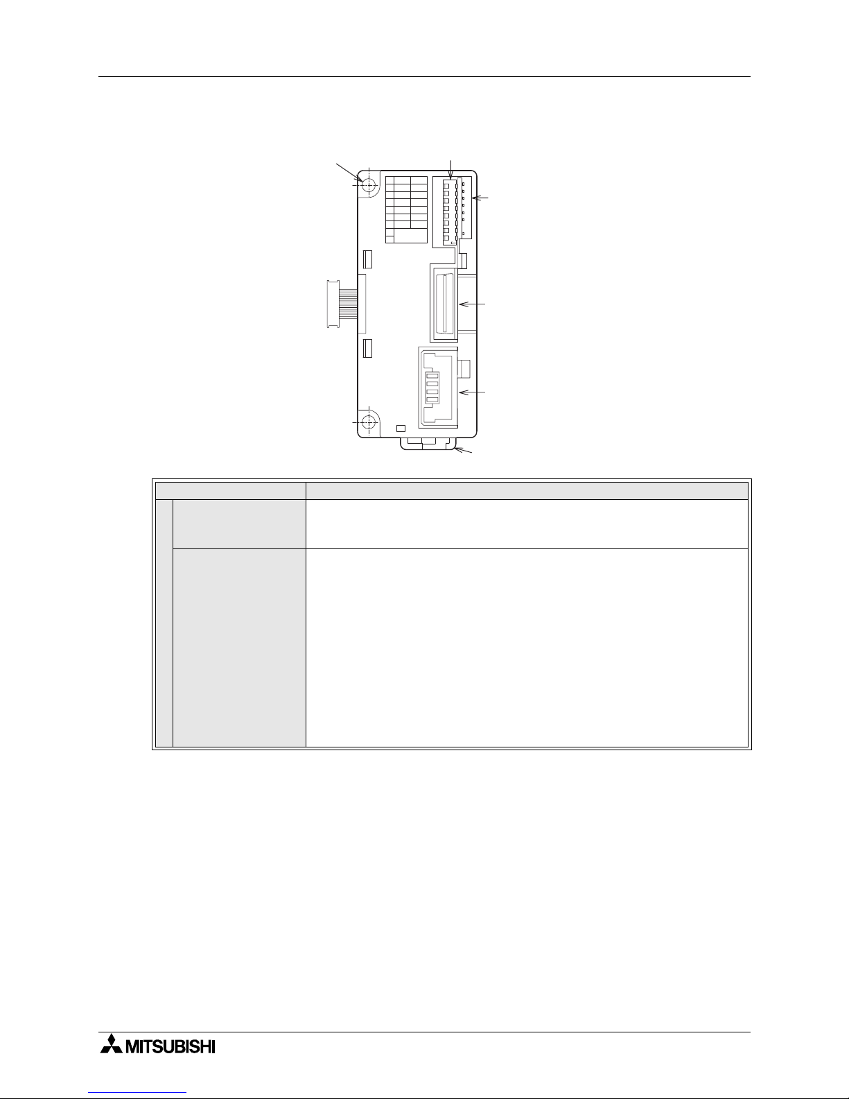
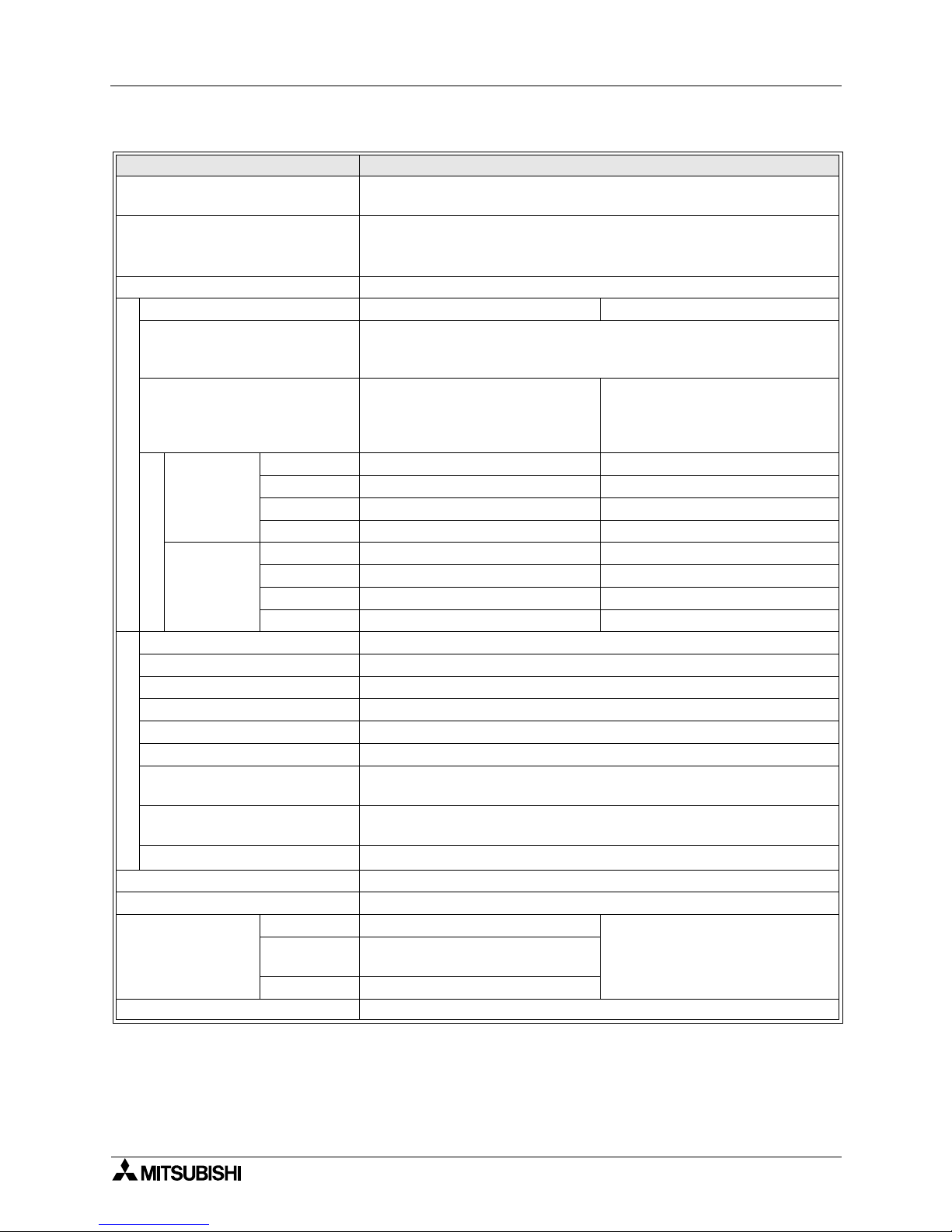
1.3 Name and assignment of each part
Name Description
Status indicator LEDs
POWER
<ONLINE mode/CONFIG mode/TEST mode>
Lit :Power is supplied
Extinguished :Power is not supplied
RUN
<ONLINE mode>
Lit :FX
2N
-64CL-M is operating normally
Extinguished :FX
2N
-64CL-M is abnormal
Power is interrupted
EEPROM read error (sum mismatch) occurred
<CONFIG mode>
Lit :FX
2N
-64CL-M is operating normally
Extinguished :FX
2N
-64CL-M is abnormal
Power is interrupted
<TEST mode>
Lit :FX
2N
-64CL-M is operating normally
Extinguished :FX
2N
-64CL-M is abnormal
Power is interrupted
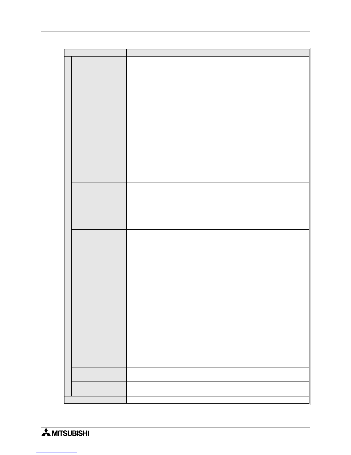
DIP switch for operation setting
Extension cable
connected to PLC
123456
7
8
OFFON
B RATE
16pts. 4pts.
ONLINE
-
TEST
-
3
2
1
4
5
6
7
8
--
CONFIG ONLINE
FX2N-64CL-M
--
O
N
Extension connector
connected to an extension
block/unit or special
block/unit of the PLC
Connector for
CC-Link/LT interface
Hook for installation to DIN rail
2-φ4.5(0.18") mounting hole
(M4 mounting screw)
Status indicator LEDs
LINK
Page 15
FX2N-64CL-M CC-Link/LT Master Block Outline 1
1-3
Status indicator LEDs
ERR.
<ONLINE mode>
Lit :Communication speed setting error occurred
EEPROM read error (sum mismatch) occurred
Flickering :Power supplied for communication is abnormal
DIP switch for operation setting was changed during
operation
Extinguished :FX
2N
-64CL-M is operating normally
<CONFIG mode>
Lit :Communication speed setting error occurred
EEPROM write error occurred
Flickering :Power supplied for communication is abnormal
DIP switch for operation setting was changed during
operation
Extinguished :FX
2N
-64CL-M is operating normally
<TEST mode>
Lit :Communication speed setting error occurred
Flickering :Power supplied for communication is abnormal
DIP switch for operation setting was changed during
operation
Extinguished :FX
2N
-64CL-M is operating normally
L RUN
<ONLINE mode/CONFIG mode>
Lit :Data link is executed
Extinguished :Data link is stopped
<TEST mode>
Lit :Self-loop back Test was finished normally
Extinguished :Self-loop back Test was finished abnormally
(Extinguished while the self-loop back Test is executed)
L ERR.
<ONLINE mode>
Lit :Use station number discrepancy
(when BFM#32(20h) to #95(5Fh) is edited, the station
numbers are checked.)
Outside-control-range station error occurred
Flickering :Stations are abnormal
Extinguished :Data link is executed normally
<CONFIG mode>
Lit :Use station number discrepancy
(When the power is turned ON while a remote module is
attached and the following setting is made: number of
connected stations varies by editing BFM#32(20h) to
#95(5Fh))
Flickering :All stations are abnormal
(When power is turned ON while no remote module is
attached and then BFM#32(20h) to #95(5Fh) is edited)
Extinguished :Data link is executed normally
<TEST mode>
Lit :Self-loop back Test was finished abnormally
Extinguished :Self-loop back Test was finished normally
(Extinguished while the self-loop back Test is executed)
SD
<ONLINE mode/CONFIG mode/TEST mode>
Lit: Data is currently being sent
RD
<ONLINE mode/CONFIG mode/TEST mode>
Lit: Data is currently being received
Interface
Connector for the flat cable dedicated to the CC-Link/LT (24G/DB/DA/+24 V)
Name Description
Page 16

FX2N-64CL-M CC-Link/LT Master Block Outline 1
1-4
• Factory default, DIP switches are set OFF.
• The Test mode is selected when both the CONFIG and TEST modes are set ON
simultaneously.
• For each setting, the status at the time of power ON is valid.
(If a setting is changed after the power is set ON, such a change is invalid.)
CONFIGMODE
• Values held in BFM #32 (20h) to #95 (5Fh) that are changed online will cause a L ERR.
• No remote module attached during power ON will result in no L ERR.
• Remote module removed during operation will result in no L ERR.
DIP switch for operation setting
1
B RATE
Communication speed setting
2
3 16pts/4pts
Point mode setting
(Select the number of I/O points per station.)
OFF:4-point mode (4 input points and 4 output points in each station)
ON :16-point mode (16 input points and 16 output points in each station)
4 --
Setting is disabled. (Make sure that it is OFF during operation.)
5 --
Setting is disabled. (Make sure that it is OFF during operation.)
6 CONFIG/ONLINE
CONFIG mode
OFF: ONLINE mode (normal operation)
ON : CONFIG mode (The information on the connected stations is saved to
the EEPROM.)
7 TEST/ONLINE
TEST mode
OFF: ONLINE mode (normal operation)
ON : TEST mode (Self-loop back Test)
8 --
Setting is disabled. (Make sure that it is OFF during operation.)
Name Description
Communication speed SW1 SW2
156 kbps OFF OFF
625 kbps ON OFF
2.5 Mbps OFF ON
Setting disabled ON ON
Page 17
Specifications 2
2-1
2. Specifications
This section explains the specifications of the FX2N-64CL-M.
DESIGN PRECAUTIONS
When a remote I/O unit fails, outputs may randomly set ON or OFF, therefore, build an
external monitoring circuit that will monitor any input signals that could cause a serious
accident.
DESIGN PRECAUTIONS
• Do not bind control and flat cables dedicated to CC-Link/LT together with power cables.
Keep control and flat cables dedicated to CC-Link/LT away from major circuits and power
cables by 100 mm (3.93") or more.
It may cause a malfunction due to noise interference.
• Use the FX
2N
-64CL-M in such status that any force is not applied on connectors for CCLink/LT interface and flat cables dedicated to CC-Link/LT.
If any force is applied, wire breakage and failure may be caused.
STARTING AND MAINTENANCE PRECAUTIONS
• Do not touch the terminals while the power is ON. It may cause an electric shock or
malfunction.
• Shut down all phases of the power supply outside the master block before starting any
cleaning procedures.
If the power is not disconnected from all sources, the FX
2N
-64CL-M may fail or
malfunction.
STARTING AND MAINTENANCE PRECAUTIONS
• Do not disassemble or modify the FX2N-64CL-M.
Doing so may cause failure, malfunction, injury, or fire.
• The case of the FX
2N
-64CL-M is made of resin.
Do not drop or apply strong impacts to the FX
2N
-64CL-M.
DISPOSAL PRECAUTIONS
• Treat the FX2N-64CL-M as industrial waste when disposing of the product.
FX2N-64CL-M CC-Link/LT Master Block
Page 18
FX2N-64CL-M CC-Link/LT Master Block Specifications 2
2-2
2.1 General specifications
2.2 Network wiring specifications
Item Specification
Operating temperature 0 to 55°C (32 to 131°F)
Storage temperature -20 to 70°C (-4 to 158°F)
Operating humidity 35 to 85%RH (Dew condensation should not be allowed.)
Vibration resistance
Conforming to
EN68-2-6
Direct mounting
Number of sweep
times
Frequency Acceleration Half amplitude
10 times in each of
the X, Y and Z
directions (for 80 min)
10 to 57Hz -- 0.075mm
57 to 150Hz 9.8m/s
2
--
DIN rail mounting
Frequency Acceleration Half amplitude
10 to 57Hz -- 0.035mm
57 to 150Hz 4.9m/s
2
--
Shock resistance
In conformance to EN 68-2-27
(147 m/s
2
, working time: 11 ms, half sine wave, three times in each of X, Y and Z
directions)
Noise immunity
By noise simulator of noise voltage = 1,000 Vp-p, noise width = 1 µs, rising = 1 ns,
cycle = 30 to 100 Hz
Dielectric withstand
voltage
500V AC for 1 min
In conformance to JEM-1021
Between case and PLC grounding
terminal
Isolation resistance 5 MW or more by 500V DC megger
Operating ambience Do not use in a corrosive gas, flammable gas or conductive dust environment.
Grounding
Grounding resistance 100W or less
(Common grounding with strong electrical systems.)
Item Specification Remarks
Communication speed 2.5Mbps 625kbps 156kbps --
Distance between stations No restriction --
Maximum number of
modules connected in 1
drop line
8 units
Maximum number of
remote I/O units
connected per branch in
a drop line
Maximum trunk length 35m (114' 9") 100m (328' 1") 500m (1640' 5")
Cable length between
terminating resistors
T-branch interval No restriction --
Maximum drop length 4m (13' 1") 16m (52' 5") 60m (196' 10") Cable length per branch
Cumulative drop line
length
15m (49' 2") 50m (164' 0") 200m (656' 2") Sum of all drop lines
Page 19
FX2N-64CL-M CC-Link/LT Master Block Specifications 2
2-3
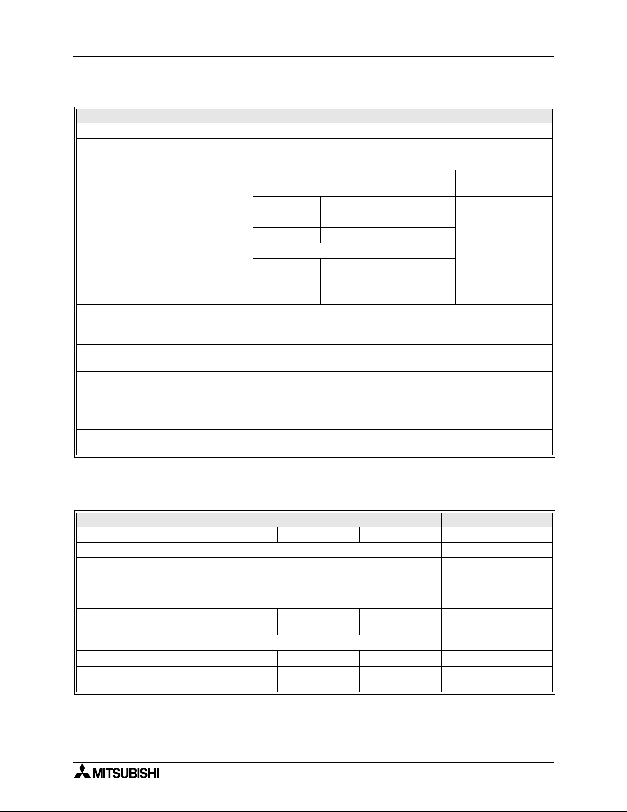
2.3 Performance specifications
*1 When connected to an FX1N Series PLC, up to two FX2N-64CL-M can be connected to each of the
main and extension units.
*2 The FX
2N
-64CL-M draws 190mA from the 5V DC source.
The total 5V consumption of all special function blocks connected to a main unit or extension unit
must not exceed the 5V source capacity of the system.
(Refer to the Hardware manual of the applicable PLC)
Item Specification
Applicable PLC
FX
1N
/FX2N/FX
2NC
Series PLC (Section 4.3)
(FX
2NC
-CNV-IF is required when FX
2NC
Series PLC is connected.)
Number of connectable master
blocks
FX
1N
Series: Up to 4
*1
FX2N Series: Up to 8
*2
FX
2NC
Series: Up to 3
*2
Applicable point mode 4-point mode and 16-point mode (selectable by DIP switch)
Control specifications
4-point mode 16-point mode
Maximum number of link points
Connected to FX
1N
Series PLC: 128 points
Connected to FX
2N
/FX
2NC
Series PLC: 256 points
(including I/O points in PLC in each case)
Number of link points per station
( ) shows the number of link
points when composite I/O
module is used.
4 points (8 points) 16 points (32 points)
Link scan time
32 stations
Points 128 points 256 points
2.5Mbps 0.7ms 1.0ms
625kbps 2.2ms 3.8ms
156kbps 8.0ms 14.1ms
64 stations
Points 256 points 256 points
2.5Mbps 1.2ms 2.0ms
625kbps 4.3ms 7.4ms
156kbps 15.6ms 27.8ms
Communication specifications
Communication speed 2.5 Mbps, 625 kbps and 156 kbps (selectable by DIP switch)
Protocol BITR method (Broadcastpolling + Interval Timed Response)
Network topology T-branch
Error control method CRC
Number of connected stations 64 stations maximum
Remote station numbers 1 to 64
Master station connection
position
Connected at end of trunk line
RAS function
Communication error detection, automatic return to system, slave station
disconnection and internal loop back diagnosis
Connection cable
Dedicated flat cable (0.75 mm
2
× 4)
Number of occupied I/O points 8 points (fixed) + Number of connected remote I/O points
Current consumption inside 5V DC 190 mA (Supplied by PLC via extension connector)
24V DC power
supply
Voltage 20.4V to 28.8V DC
Supplied from power adapter via
connector for flat cable dedicated to
CC-Link/LT.
Current
consumption
25 mA
Initial current 35 mA
Mass (weight) 0.15 kg (0.33 lbs)
Page 20

FX2N-64CL-M CC-Link/LT Master Block Specifications 2
2-4
2.4 Outside Dimensions
FX2N-64CL-M
FX
2N
-64CL-M
RUN
ERR.
L RUN
L ERR.
SD
RD
POWER
43(1.70)
4(0.16)
2-φ4.5(0.18)
87(3.43)
90(3.55)
80(3.15)±0.5(0.02)(mounting size)
Unit: mm(inches)
Page 21
System Startup Procedure 3
3-1
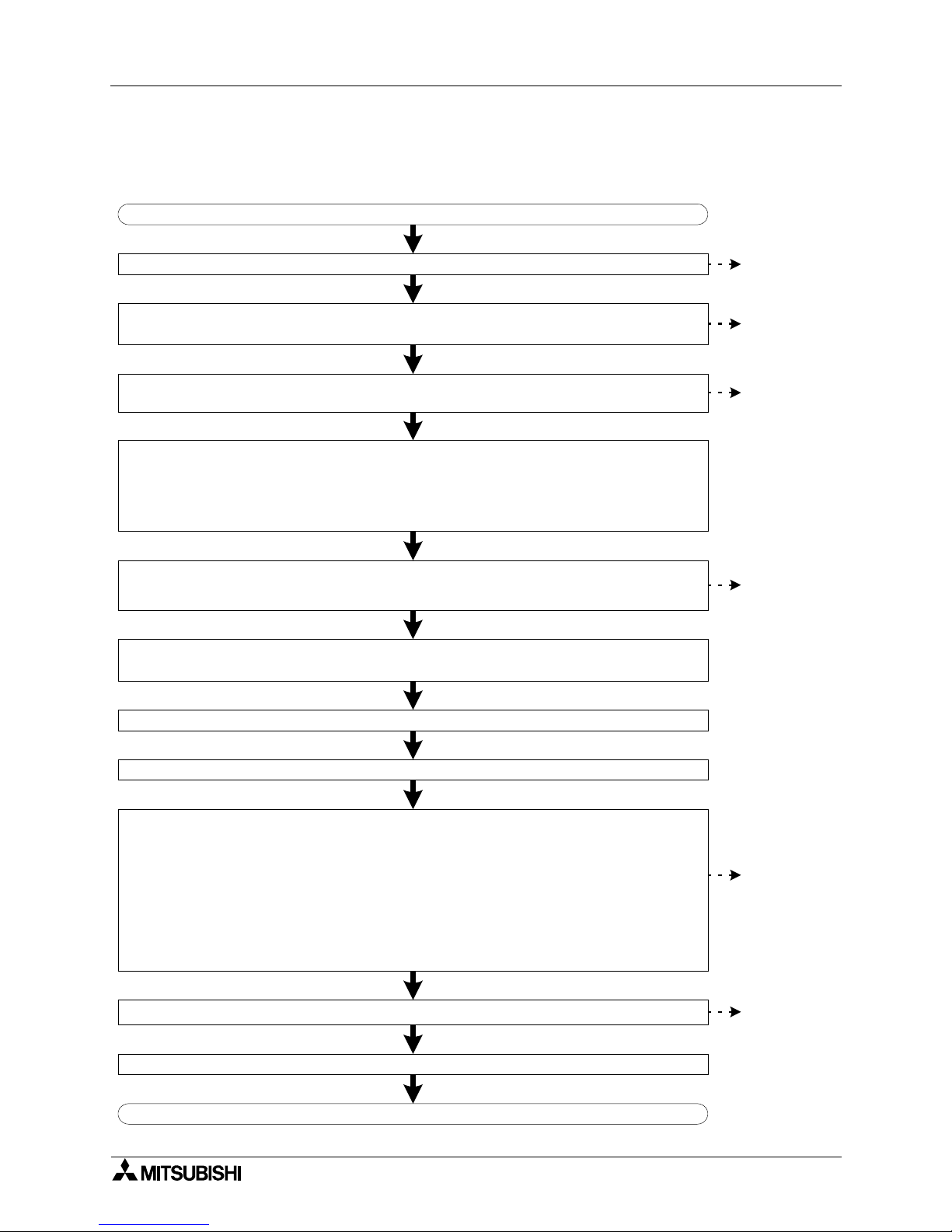
3. System Startup Procedure
Start up the CC-Link/LT system using the following procedure.
Start
Install the FX2N-64CL-M, remote I/O units and power adapter to the control panel and machine.
Connect the FX2N-64CL-M, remote I/O units and power adapter with the dedicated flat cables.
Connect terminating resistors at the both ends of the trunk line.
Terminating CONFIG mode
Turn OFF the power to the power adapter and main unit.
Set the DIP switch in the FX2N-64CL-M to the ONLINE mode.
Supply power to the power adapter before the main unit.
Confirming the operation based upon LEDs
FX
2N
-64CL-M
- Data link is normal: L RUN is lit.
- Data link is abnormal: L ERR. is lit or flickering.
- Setting is abnormal: The ERR. is lit.
Remote I/O unit
- Confirm remote station connection by checking buffer memory [BFM #0 (0h) to
#3 (3h)] in the FX
2N
-64CL-M.
- Confirm device operation using peripheral equipment for the PLC (with regard to monitorly and
forcing inputs + outputs ON and OFF).
Write a control program to the main unit.
Operate the system.
End
Set the transmission speed, point mode, station No., etc. of the FX2N-64CL-M and remote I/O units
using the DIP switches. (Set the FX2N-64CL-M to the CONFIG mode.)
Check the following items before turning the power ON.
- Confirm the installation status of the FX
2N
-64CL-M, remote I/O units and power adapter.
- Confirm the supply voltage for the power adapter.
- Confirm that the RUN/STOP switch for the main unit is set to STOP.
- Confirm that the same station No. is not used in two or more remote I/O units.
Executing CONFIG mode
Supply power to the power adapter before the main unit.
(Specify reserved stations and edit the detailed remote station information here if necessary.)
Refer to
Section 5.
Refer to
Section 6.
Refer to
Sections 1
and 7.
Refer to
Section 8.
Refer to
Sections 10
and 12.
Refer to
Section 11.
FX2N-64CL-M CC-Link/LT Master Block
Page 22

FX2N-64CL-M CC-Link/LT Master Block System Startup Procedure 3
3-2
MEMO
Page 23

System Configuration 4
4-1
4. System Configuration
This section explains the CC-Link/LT system configuration.
DESIGN PRECAUTIONS
When a remote I/O unit fails, outputs may randomly turn ON or OFF, therefore, build an
external monitoring circuit that will protect from any input signals that could cause a serious
accident.
DESIGN PRECAUTIONS
• Do not bind control cables and flat cables dedicated to CC-Link/LT together with power
cables.
Keep control cables and flat cables dedicated to CC-Link/LT away from major circuits and
power cables by 100 mm (3.93") or more.
It may cause a malfunction due to noise interference.
• Use the FX
2N
-64CL-M in anenvironment status that any force is not directly applied on
connectors for
CC-Link/LT interface and flat cables dedicated to CC-Link/LT.
If any force is applied, wire breakage and failure may occur.
FX2N-64CL-M CC-Link/LT Master Block
Page 24

FX2N-64CL-M CC-Link/LT Master Block System Configuration 4
4-2
4.1 Total configuration
This paragraph describes the system configuration and cautions for CC-Link/LT.
• Connect the master station, power adapter and remote stations using the flat cables
dedicated to CC-Link/LT and the connectors for dedicated flat cables.
• The connection order of remote stations has no relevance to the station No.
Even if the station No. of remote stations is not consecutive, no error will occur in the data
link.
• In the CC-Link/LT system, terminating resistors should be connected to both ends of the
trunk line.
Connect the terminating resistor on the FX
2N
-64CL-M side to a position within 200 mm
(7.87") from the FX
2N
-64CL-M.
• Make sure to lay out the master block on one side of the trunk line.
• Up to 64 remote stations can be connected to one FX
2N
-64CL-M as far as the condition
shown in the table below are satisfied.
• Equipment for CC-Link cannot be connected to the CC-Link/LT system.
On the contrary, equipment for CC-Link/LT cannot be connected to the CC-Link system.
• Refer to the respective instruction manuals when installing the power adapter or remote I/O
units.
• Refer to the homepage of the CC-Link Partner Association (CLPA) "http://www.cc-link.org/"
for details concerning flat cabling, terminating resistors and connector for CC-Link/LT.
Item Specification Remarks
Communication speed 2.5Mbps 625kbps 156kbps --
Distance between
stations
No restriction --
Maximum number of
modules connected in 1
drop line
8 units
Maximum number of
remote I/O units connected
per branch in a drop line
Maximum trunk length 35m (114' 9") 100m (328' 1") 500m (1640' 5")
Cable length between
terminating resistors
(excluding drop line length)
T-branch interval No restriction --
Maximum drop length 4m (13' 1") 16m (52' 5") 60m (196' 10") Cable length per branch
Cumulative drop line
length
15m (49' 2") 50m (164' 0") 200m (656' 2") Sum of all drop lines
PLC main unit
Terminating
resistor
T branch
connection
T-branch interval
Power
adapter
Remote
I/O station
Remote
I/O station
Drop length
(including branch)
Remote
I/O station
Remote
I/O station
Remote
I/O station
Remote
I/O station
Distance between
stations
Terminating
resistor
Trunk length (branch line length not included)
Trunk line
Drop line
Page 25

FX2N-64CL-M CC-Link/LT Master Block System Configuration 4
4-3
4.2 PLC connection
This paragraph explains which PLC series are connectable with the FX2N-64CL-M and
cautions on the number of connectable FX
2N
-64CL-M.
4.2.1 Applicable PLC and number of connectable FX
2N
-64CL-M
• Connect the FX
2N
-64CL-M to the right side of the PLC using an extension cable.
• The number of occupied I/O points is "8 (either input or output) points + Number of
connected remote I/O points".
The total number of I/O points including extended points must not exceed 128 points for the
FX
1N
Series or 256 points for the FX2N or FX
2NC
Series.
• The FX
2N
-64CL-M consumes 190 mA at 5V DC.
The total current consumption at 5V for special blocks connected to the PLC must not
exceed the 5 V power capacity of the main and extension units.
When connecting to the FX
1N
Series PLC, a maximum of two FX2N-64CL-M can be
connected to each of the main and extension units.
4.3 Power adapters installation concept
At least one power adapter is required per CC-Link/LT system.
When constructing a system using only one power adapter, the following three conditions
should be satisfied:
1) Total current consumption of remote I/O units, I/O equipment and master unit receiving
power from power adapter ≤ 5 A
2) To operate the system in a stable environment, the voltage drop should be equivalent to or
less than 3.6V.
3) Because the minimum operating voltage of each remote I/O unit connected to the power
adapter is 20.4 V, therefore, Supply voltage to power adapter - Voltage drop ≥ 20.4 V
If the total current consumption or voltage drop is large, the power adapter position should be
changed or additional power adapters should be installed.
For further details, refer to the "CL1PAD1 (Power Adapter) USER'S MANUAL (Detailed
Volume)" offered separately.
4.4 Power adapter installation condition
For further details on power adapter installation conditions, refer to the "CL1PAD1 (Power
Adapter) USER'S MANUAL (Detailed Volume)" offered separately.
The conditions for installing power adapters to the CC-Link/LT system depend on connected
equipment and wiring length.
Applicable PLC
FX
1N
/FX2N/FX
2NC
Series PLC
(FX
2NC
-CNV-IF is required when FX
2NC
Series PLC is connected.)
Number of connectable
master blocks
FX
1N
Series: Up to 4
FX
2N
Series: Up to 8
FX
2NC
Series: Up to 3
Page 26

FX2N-64CL-M CC-Link/LT Master Block System Configuration 4
4-4
MEMO
Page 27

Handling Cautions 5
5-1
5. Handling Cautions
INSTALLATION PRECAUTIONS
• Use the FX2N-64CL-M in an environment with the general specifications described in this
manual.
If the FX
2N
-64CL-M is used in any other environment, thus, electrical shock, fire,
malfunction, product damage or product deterioration may occur.
• Do not directly touch the conductive area of the FX
2N
-64CL-M, otherwise, the
FX
2N
-64CL-M may malfunction or fail.
• Shut down all power supplies before attaching/removing the FX
2N
-64CL-M to/from the
panel, otherwise, the FX
2N
-64CL-M may fail or malfunction.
• Securely fix the FX
2N
-64CL-M with DIN rail or mounting screws. When using mounting
screws, securely tighten them within the specified torque range.
If the screws are too loose, the module may detach from its installed position, short
circuit, or malfunction. If the screws are too tight, the screws may be damaged, which
may cause the module to detach from its installed position or short circuit.
• Install the FX
2N
-64CL-M on to a flat surface.
If the installation surface is not flat, an excessive force may be applied on the PCBs,
leading to nonconformity.
FX2N-64CL-M CC-Link/LT Master Block
Page 28

FX2N-64CL-M CC-Link/LT Master Block Handling Cautions 5
5-2
5.1 Installation
The FX2N-64CL-M can be attached via DIN rail or attached directly with screws.
The installation procedure in each case is described below.
5.1.1 Installation direction
• Do not install the master block on floor surfaces, ceiling surfaces or in a horizontal direction.
If the master block is installed in such a way, its temperature may rise.
Install the master block vertically on wall surfaces as shown in the figure below.
• Secure a space of 50 mm (1.96") or more between the master block and other equipment or
structures. Keep the master block off high voltage cables, high voltage equipment and
power equipment as much as possible.
5.1.2 DIN rail installation
Align the upper DIN rail installation groove in the module with the DIN rail 1), and press the
module in that position 2).
When removing the module, pull the installation hook downwards 3), then remove the module
4).
5.1.3 Direct installation
Fix the FX
2N
-64CL-M on to the panel surface by tightening M4 screws inserted in two (upper
and lower) mounting holes provided on the master block.
Install the FX
2N
-64CL-M and other units so that a clearance of 1 to 2 mm is assured among
each unit.
Applicable DIN rail TH35-7.5Fe and TH35-7.5AI (conforming to JIS C2812)
Applicable screw M4 height: 16mm(0.63") or more (Tightening torque range: 78 to 108 N
⋅⋅⋅⋅
cm)
1)
Installation Removal
2)
3)
4)
Page 29

Connection of Cables, Connectors and Terminating Resistors 6
6-1
6. Connection of Cables, Connectors and Terminating Resistors
Connect the master station, power adapter and remote stations with flat cables dedicated to
CC-Link/LT and connectors for dedicated flat cables.
Lay out the master block on one side of the trunk line.
WIRING PRECAUTIONS
• Shut down all power supplies before starting installation or wiring work.
If the power is not disconnected from all sources an electric shock or serious product
damage may occur.
WIRING PRECAUTIONS
• Correctly wire the master block while confirming the rated voltage and terminal
arrangement of the FX
2N
-64CL-M.
If a power supply different from the rated supply is connected or wiring is performed
incorrectly, fire or failure may be caused.
• Correctly wire the master block while confirming the rated voltage and terminal
arrangement of the FX
2N
-64CL-M.
If a power supply different from the rated supply is connected or wiring is performed
incorrectly, fire or failure may occur.
• Pay attention to foreign objects such as cuttings or wiring chips do not enter the
FX
2N
-64CL-M, otherwise, fire, product failure or malfunction may occur.
FX2N-64CL-M CC-Link/LT Master Block
Page 30

FX2N-64CL-M CC-Link/LT Master Block Connection of Cables, Connectors and Terminating Resistors 6
6-2
6.1 Connection of units using flat cables dedicated to CC-Link/LT
This paragraph explains the connection method using flat cables dedicated to CC-Link/LT.
1) The connection order of dedicated flat cables has no relevance to the station No.
2) Lay out the FX
2N
-64CL-M at either end of the trunk line.
Connect a terminating resistor on the FX
2N
-64CL-M side in a position that is within 20 cm
from the FX
2N
-64CL-M.
3) Make sure to connect a terminating resistor to each end of the trunk line the CC-Link/LT.
Connect T-branches and remote I/O units using the connectors for dedicated flat cable.
6.2 How to attach connectors used for dedicated flat cable
This paragraph explains how to attach connectors used for the dedicated flat cable.
1) Components
The components are as shown below.
T-branch area
Master station/remote station/power adapter connection area
Trunk line
Drop line
Connector for dedicated
flat cable
Connector for
dedicated
flat cable
Connector for dedicated
flat cable
-Master station (FX
2N
-64CL-M)
-Power adapter (CL1PAD1)
-Terminal block type remote
I/O unit
-Sensor connector type remote
I/O unit
-MIL collector type remote I/O unit
Connector for
dedicated
flat cable
Cable type
remote I/O unit
Connector for dedicated
flat cable
C o m p o n e n t 1 : C o v e r C o m p o n e n t 2 : B o d y
C o m p o n e n t 3 : D e d i c a t e d f l a t
c a b l e
O r a n g e c o l o r
Page 31

FX2N-64CL-M CC-Link/LT Master Block Connection of Cables, Connectors and Terminating Resistors 6
6-3
2) Attachment procedure
The procedure is shown below.
a) Terminal processing procedure
b) T-branch processing procedure
1 ) C o r r e c t l y s e t t h e d e d i c a t e d f l a t
c a b l e o n t h e c o v e r . ( P a y a t t e n t i o n
t o t h e o r a n g e c o l o r l o c a t i o n o f t h e
d e d i c a t e d f l a t c a b l e . )
N o t e 1 : T h i s d i r e c t i o n i s w r o n g .
O r a n g e c o l o r
O r a n g e c o l o r
O r a n g e c o l o r
2 ) C l o s e t h e c o v e r t o f i r m l y h o l d t h e
d e d i c a t e d f l a t c a b l e .
3 ) C o m b i n e t h e b o d y w i t h t h e c o v e r ,
a n d p r e s s - f i t t h e m w i t h p l i e r s , e t c .
4 ) C o n f i r m t h a t t h e l a t c h i s e n g a g e d
i n f o u r p o s i t i o n s .
N o w , p r e s s - f i t t i n g i s f i n i s h e d .
O r a n g e c o l o r
N o t e 2 :
O r a n g e c o l o r
O r a n g e c o l o r
I f t h e o r a n g e d e d i c a t e d f l a t
c o v e r c a n b e s e e n f r o m t h e
n o t c h e d w i n d o w i n t h e f r o n t ,
t h e w i r i n g i s w r o n g . O p e n t h e
c o v e r , a n d c o r r e c t l y s e t t h e
d e d i c a t e d f l a t c o v e r .
5 ) C u t o f f t w o p o s i t i o n s a t t h e r o o t o f
t h e t i p o f t h e c o v e r w i t h n i p p e r s ,
e t c . , a n d r e m o v e t h e t i p .
O r a n g e c o l o r
6 ) S e t t h e c o v e r t o t h e p o s i t i o n i n
w h i c h T - b r a n c h w i l l b e s e t .
7 ) E x e c u t e p r e s s - f i t t i n g i n t h e s a m e
w a y a s i n s t e p s 3 ) a n d 4 ) a b o v e .
C u t o f f h e r e .
O r a n g e c o l o r
Page 32

FX2N-64CL-M CC-Link/LT Master Block Connection of Cables, Connectors and Terminating Resistors 6
6-4
6.2.1 How to attach terminating resistor
This paragraph explains how to attach terminating resistors to either end of the CC-Link/LT
system.
Attach terminating resistors to the connectors placed to flat cables dedicated to CC-Link/LT.
1) How to attach a terminating resistor on the FX
2N
-64CL-M side
The method to attach a terminating resistor on the FX
2N
-64CL-M side is shown below.
Connect a terminating resistor in a position within 200mm (7.87") from the FX
2N
-64CL-M.
2) How to attach a terminating resistor on the trunk line side
The method to attach a terminating resistor on the opposite side of the FX
2N
-64CL-M is
shown below.
Terminating resisto
r
Connector for dedicated
flat cable
FX2N-64CL-M
Terminating
resistor
FX2N-64CL-M
Connector for
dedicated flat
cable
Within 200mm (7.87")
from the FX
2N-64CL-M
Terminating
resistor
Connector for
dedicated flat cable
Page 33

FX2N-64CL-M CC-Link/LT Master Block Connection of Cables, Connectors and Terminating Resistors 6
6-5
6.2.2 Wiring check
Confirm the wiring between remote I/O units and external equipment.
Example of wiring check
The figure below shows an example in which the head I/O No. in the FX
2N
-64CL-M is X020/
Y020 and 4-point mode is selected.
Operating procedure
1) Connect the FX
2N
-64CL-M, power adapter and remote I/O units using the dedicated cables.
Set the transmission speed, point mode, station No., etc. using the DIP switches in the
FX
2N
-64CL-M and remote I/O units.
At this time, select the CONFIG mode in the FX
2N
-64CL-M (by setting bit 6 ON and setting
bit 7 OFF).
2) Supply power to the power adapter before the PLC unit.
3) When the acquisition of remote I/O unit information is completed in the CONFIG mode (that
is, when b4 of the BFM #28 (1Ch) turns ON), turn the power OFF.
4) Set the FX
2N
-64CL-M to ONLINE mode (by setting bit 6 OFF and bit 7 OFF). Supply power
to the power adapter before the FX
2N
-64CL-M. Then, execute step a) or b) below.
a) Checking the wiring between the input unit and external equipment
- Turn ON the switch corresponding to "X020" of the external equipment connected to
the input unit with station No. is 1.
- Monitor X020 from peripheral equipment.
- If X020 is ON, connection between the input unit and external equipment is normal.
b) Check the wiring between the output unit and external equipment
- Turn Y020 ON/OFF from peripheral equipment using the forced ON/OFF operation.
- If the connection between the output unit and external equipment is normal, a lamp
corresponding to "Y020" in the external equipment will light.
FX2N-64CL-M
(X020/Y020, 4-point mode)
4-point input unit
CL1X4-D1B2
(station No. = 1,
number of occupied
stations = 1)
X020
ON
ON
Y020
Power
adapter
4-point output unit
CL1Y4-T1B2
(station No. = 2,
number of occupied
stations = 1)
PLC main
unit
Terminating
resistor
Terminating
resistor
Page 34

FX2N-64CL-M CC-Link/LT Master Block Connection of Cables, Connectors and Terminating Resistors 6
6-6
MEMO
Page 35

Various Modes 7
7-1
7. Various Modes
The FX2N-64CL-M has ONLINE, CONFIG and TEST modes.
Each mode can be selected using the appropriate DIP switch.
(Turn OFF the power to the PLC before setting the DIP switches.)
7.1 ONLINE mode (DIP switch bit 6 = OFF, bit 7 = OFF)
In ONLINE mode, the FX2N-64CL-M will execute the data link in the CC-Link/LT system.
Select this mode for normal use.
7.2 CONFIG mode (DIP switch bit 6 = ON, bit 7 = OFF)
In CONFIG mode, the FX2N-64CL-M assigns the station No. and I/O Nos. for remote stations.
The FX
2N
-64CL-M acquires the information (I/O type and number of points) on the connected
remote stations, then stores it to the buffer memory [BFM #32 (20h) to #95 (5Fh)] and built-in
memory (EEPROM).
After constructing the CC-Link/LT system, execute the CONFIG mode to automatically assign
the I/O Nos.
(After constructing the CC-Link/LT system, assign the I/O Nos. by executing the CONFIG
mode.)
If remote stations are to be extended in the future, the I/O Nos. can be assigned while skipping
some I/O Nos.
For the details of assignment of the I/O Nos., refer to "8. Assignment of I/O Nos."
7.3 TEST mode (self-loop-back test) (DIP switch bit 6 = OFF, bit 7 = ON)
In TEST mode (for the self-loop-back test), the FX2N-64CL-M checks whether it is fully
functional by receiving data sent by itself.
In this test, it is not necessary to connect remote stations.
(Connect the FX
2N
-64CL-M to the power adapter, then turn ON the communication power.)
For details on the self-loop-back test, refer to "12.4 Self-loop-back test".
• When the FX
2N
-64CL-M is set to the TEST mode while it is connected to a FX1N Series
PLC, the PLC is stopped.
(The self-loop-back test will be executed normally, and the test result will be indicated by the
status indicator LEDs.)
FX2N-64CL-M CC-Link/LT Master Block
Page 36

FX2N-64CL-M CC-Link/LT Master Block Various Modes 7
7-2
MEMO
Page 37

Assignment of I/O Nos. 8
8-1
8. Assignment of I/O Nos.
The FX2N-64CL-M assigns I/O information for remote I/O units to devices X (input) and Y
(output) in the PLC.
The I/O Nos. are assigned in CONFIG mode.
At this time, the I/O Nos. are assigned in octal serial Nos. following the I/O No. occupied by the
PLC while eight points are handled as one block.
(For further details, refer to "8.2 Example of I/O No. assignment")
For a station No. to which a remote I/O unit will be connected to in the future, the I/O No. can
be secured by "specifying it as a reserved station" and "editing the detailed remote station
information on it".
8.1 Relationship between I/O No. and point mode
The I/O No. is equivalent between the 4-point mode and 16-point mode, but the station No. of
each remote station is different between 4-point mode and 16-point mode.
When using remote I/O units of more than 4 I/O points, more I/O points can be used if the 16point mode is selected due to the restriction in the number of connected stations
(64 stations maximum).
Example:When sixty-three CL1XY2-DT1D5S units (cable type remote unit having 1 input point
and 1 output point) (station No.: 1 to 63) and one CL2X8-D1B2 unit (terminal block
type remote I/O unit having 8 input points) are to be connected to the FX
2N
-16MR, a
system can be constructed in the 16-point mode, but cannot be constructed in the 4point mode due to the CL2X8-D1B2 unit occupying two stations and the number of
remote stations exceeds 64.
However, if the number of stations is equivalent, the link scan time is longer in the 16-point
mode than in the 4-point mode.
(For further details of the link scan, refer to "9. Data Link Processing Time".)
1) When connecting all remote I/O units and assigning their I/O Nos., refer to "8.3 Automatic
I/O No. assignment".
2) When assigning the I/O Nos. without connecting remote I/O units and preparing a sequence
program or connecting additional remote I/O units in the future, refer to "8.3 Automatic I/O
No. assignment" and "8.4 Specification of reserved station" and "8.5 Edition of detailed
remote station information".
• In CONFIG mode, the FX
2N
-64CL-M does not occupy I/O points for remote stations.
(It occupies only 8 points as a special block.)
I/O extension blocks/units of the PLC connected after the FX
2N
-64CL-M do not operate.
FX2N-64CL-M CC-Link/LT Master Block
Page 38

FX2N-64CL-M CC-Link/LT Master Block Assignment of I/O Nos. 8
8-2
8.2 Example of I/O No. assignment
This paragraph describes I/O No. assignment in the configuration example shown below.
When the FX
2N
-64CL-M is set to the CONFIG mode and the PLC is powered ON, the FX2N64CL-M checks for connected remote stations, and assigns the I/O No. to each remote station.
Though the I/O No. is equivalent between the 4-point mode and 16-point mode, the station No.
of each remote station is different between the 4-point mode and 16-point mode.
In the configuration example above, the link scan time is longer in the 16-point mode than in
the 4-point mode.
(For the details of the link scan, refer to "9. Data Link Processing Time".)
*1 With regard to X and Y, 8 points are occupied as 1 block. As a result, if the number of I/O
points occupied by a station is a number which cannot be divided by "8", unused Nos. are
generated.
In the configuration example above, the I/O Nos. are assigned as shown below.
Station No.
Number of points I/O assignment (X) I/O assignment (Y)
4-point mode 16-point mode
Station No.1 Station No.1 4 input points X040 to X043 --
Station No.2 Station No.2 2 output points -- Y020 to Y021
Station No.3 Station No.3 16 input points X044 to X063 --
Station No.7 Station No.4
2 input points/
2 output points
X064 to X065 Y022 to Y023
Station No.8 Station No.5 4 input points X066 to X071 --
Unused I/O
*1
X072 to X077 Y024 to Y027
PLC
FX2N-32MT
I/O extension
block
FX2N-16EX
Master block
FX2N-64CL-M
Station No. when the 16-point mode is selected
4 input
points
2 output
points
16 input
points
2 I/O
points
4 input
points
PLC
FX2N-32MT
I/O extension
block
FX2N-16EX
Master block
FX2N-64CL-M
Station
No.1
4 input
points
Station
No. 2
2 output
points
Station
No.3
16 input
points
Station
No. 4
2 I/O
points
Station
No.5
4 input
points
Station No. when the 16-point mode is selectedY000 to Y017 (octal)
X040 to X043 Y020 to Y021 X044 to X063 X064 to X065
Y022 to Y023
X066 to X071
X000 to X037 (octal)
Page 39

FX2N-64CL-M CC-Link/LT Master Block Assignment of I/O Nos. 8
8-3
8.3 Automatic I/O No. assignment
The I/O Nos. can be assigned automatically in the CONFIG mode.
Parameter settings and sequence programs are not necessary for this assignment.
8.3.1 Automatic I/O No. assignment procedure
Execute the steps 1) to 3) below to automatically assign the I/O Nos.
1) Connect each remote I/O unit to the FX
2N
-64CL-M. In the FX2N-64CL-M, set bit 6 of the DIP
switch to ON, and set bit 7 (to select the CONFIG mode) to OFF. Power up, first, the power
adapter, then, the PLC.
The FX
2N
-64CL-M acquires the information (I/O type and number of points) on connected
remote stations, and stores it to the buffer memory [BFM #32 (20h) to #95 (5Fh)] and builtin memory (EEPROM).
2) Confirm that the contents of the buffer memory [BFM #32 (20h) to #95 (5Fh)] are consistent
with the actual system configuration.
3) Set bit 6 of the DIP switch in the FX
2N
-64CL-M to OFF. Reset the power to the PLC.
The FX
2N
-64CL-M reads the information on connected remote stations from the built-in
memory (EEPROM), and assigns the I/O No.
8.4 Specification of reserved station
The FX2N-64CL-M assigns the I/O No. in the CONFIG mode. If remote stations will be added in
the future, temporary I/O Nos. can be assigned (specification of reserved stations).
By this function, even if remote stations are added, it is not necessary to change the I/O Nos.
assigned to other remote stations and extension blocks/units connected to the PLC.
If remote stations are connected in places for reserved station, the connected remote stations
can operate with the existing setting, but errors such as wire breakage cannot be detected.
After connecting remote additional stations, execute automatic I/O No. assignment in the
CONFIG mode again. The system will update the detailed remote station information, and the
new remote stations will be able to be used normally (errors will be detected).
Page 40

FX2N-64CL-M CC-Link/LT Master Block Assignment of I/O Nos. 8
8-4
8.4.1 Reserved station setting method
Set reserved stations using the steps 1) to 4) below.
1) Set the FX
2N
-64CL-M to the CONFIG Mode (by setting bit 6 of the DIP switch to ON and
setting bit 7 to OFF). Power up the FX
2N
-64CL-M.
(The FX
2N
-64CL-M will assign the I/O Nos.)
2) Write the information (station type and number of I/O points) for the station to be added in
the detailed remote station information buffers [BFM #32 (20h) to #95 (5Fh)]. Set the
reserved station flag (bit 15) to ON in the appropriate BFM.
(If the bit for reserved station is set to OFF, errors such as wire breakage are detected while
a remote station is not connected.)
3) Give the instruction to write to the EEPROM [by setting from OFF to ON b4 of the BFM #27
(1Bh)].
4) After setting reserved stations, confirm that write to the EEPROM is completed by checking
b4 of the BFM #28 (1Ch). Then, set the power of the FX
2N
-64CL-M ON using the normal
procedure (setting the bit 6 of the DIP switch to OFF), and confirm that the detailed remote
station information [BFM #32 (20h) to #95 (5Fh)] is updated.
Configuration of detailed remote station information
Buffer memory No. Description
BFM #32(20h) Remote station information area for the station No.1
BFM #33(21h) Remote station information area for the station No.2
.
.
.
.
.
.
BFM #95(5Fh) Remote station information area for the station No.64
Bit Function 1(ON) 0(OFF)
b0
Number of I/O points
00001:1point 00101:5points 01001: 9points
01101:13points 00010:2points 00110:6points
01010:10points 01110:14points 00011:3points
00111:7points 01011:11points 01111:15points
00100:4points 01000:8points 01100:12points
10000:16points
The bits above are in the order "b4, b3, b2, b1, b0".
b1
b2
b3
b4
b5 to b7 (Setting prohibited) Set these bits to 0.
b8 Input flag Input is given. Input is not given.
b9 Output flag Output is given. Output is not given.
b10 (Setting prohibited) Set these bits to 0.
b11 Head station flag This is the head station. This is not the head station.
b12 Input filter setting High-speed input General-purpose input
b13 Output hold/clear setting HOLD CLEAR
b14 (Setting prohibited) Set these bits to 0.
b15 Reserved station flag
This is specified as reserved
station.
This is not specified as
reserved station.
Page 41

FX2N-64CL-M CC-Link/LT Master Block Assignment of I/O Nos. 8
8-5
8.5 Editing the detailed remote station information
After assigning the I/O Nos. in the CONFIG mode, the I/O No. assignment in each station No.
can be edited.
With this function, the number of I/O points can be changed, and the I/O Nos. can be assigned
to unconnected station Nos. for future use. If remote stations are added in the future, it is not
necessary to change the I/O Nos. in other remote stations and extension blocks/units
connected to the PLC.
If a remote station is not connected to an edited station No., errors such as wire breakage error
will occur.
If a remote station is connected to an edited station No. the remote station will operate with the
existing setting.
8.5.1 How to edit detailed remote station information
Edit the detailed remote station information using the steps 1) to 4) below.
1) Set the FX
2N
-64CL-M to the CONFIG Mode (by setting bit 6 of the DIP switch to ON and
setting bit 7 to OFF). Set the power of the FX
2N
-64CL-M to ON.
(The FX
2N
-64CL-M will assign the I/O Nos.)
2) Write the information (station type and number of I/O points) for the station to be added in
the detailed remote station information buffers [BFM #32 (20h) to #95 (5Fh)]. Set the
reserved station flag (bit 15) to OFF in the appropriate BFM.
(If the bit for reserved station is set to ON, the station is regarded as a reserved one, and
errors such as wire breakage error cannot be detected.)
3) To the detailed remote station information on every remote station to be edited, write the
information on the remote station. Then, give the instruction for write to the EEPROM [by
setting b4 of the BFM #27 (1Bh) from OFF to ON].
4) After editing the remote station information, confirm that write to the EEPROM is completed
by checking b4 of the BFM #28 (1Ch). Then, set the power of the FX
2N
-64CL-M to ON using
the normal procedure (by setting bit 6 of the DIP switch to OFF), and confirm that the
detailed remote station information [BFM #32 (20h) to BFM #95 (5Fh)] is updated.
Buffer memory No. Description
BFM #32(20h) Remote station information area for the station No.1
BFM #33(21h) Remote station information area for the station No.2
.
.
.
.
.
.
BFM #95(5Fh) Remote station information area for the station No.64
Page 42

FX2N-64CL-M CC-Link/LT Master Block Assignment of I/O Nos. 8
8-6
Configuration of detailed remote station information
Bit Function 1(ON) 0(OFF)
b0
Number of I/O points
00001:1point 00101:5points 01001: 9points
01101:13points 00010:2points 00110:6points
01010:10points 01110:14points 00011:3points
00111:7points 01011:11points 01111:15points
00100:4points 01000:8points 01100:12points
10000:16points
The bits above are in the order "b4, b3, b2, b1, b0".
b1
b2
b3
b4
b5 to b7 (Setting prohibited) Set these bits to 0.
b8 Input flag Input is given. Input is not given.
b9 Output flag Output is given. Output is not given.
b10 (Setting prohibited) Set these bits to 0.
b11 Head station flag This is the head station. This is not the head station.
b12 Input filter setting High-speed input General-purpose input
b13 Output hold/clear setting HOLD CLEAR
b14 (Setting prohibited) Set these bits to 0.
b15 Reserved station flag
This is specified as reserved
station.
This is not specified as
reserved station.
Page 43

Data Link Processing Time 9
9-1
9. Data Link Processing Time
This section explains the link scan time and transmission delay time.
9.1 Link scan time
This paragraph explains the link scan time for the CC-Link/LT network.
9.1.1 Link scan time calculation formula
Link scan time = a + ( b × N ) × c [µs]
a: Constant (depends on the transmission speed)
b: Constant (depends on the transmission speed and point mode)
c: Constant (depends on the transmission speed)
N: Final station No.
As shown in the formula above, if the number of stations is held constant, the link scan time is
shorter in the 4-point mode than in the 16-point mode.
Transmission speed 2.5Mbps 625kbps 156kbps
Value a 22 88 353
Transmission speed 2.5Mbps 625kbps 156kbps
Value b
4-point mode 46 41 37
16-point mode 76 71 67
Transmission speed 2.5Mbps 625kbps 156kbps
Value c 0.4 1.6 6.4
0204060
Number of
stations
0
0.5
1.0
1.5
2.0
2.5
16-point mode
4-point mode
Link scan time (ms)
Link scan time (at 2.5 Mbps)
FX2N-64CL-M CC-Link/LT Master Block
Page 44

FX2N-64CL-M CC-Link/LT Master Block Data Link Processing Time 9
9-2
9.1.2 Transmission delay time
The transmission delay time (the time until data is received) (including the time for
communication between the main unit and FX
2N
-64CL-M) can be calculated by the following
formula.
1) Master station ← Remote station (input)
Time until a device (X) in the main unit turns ON or OFF after a signal is input to the remote
station
Calculation formula
SM
×
2 + (2 - n)*1 × LS + Remote station input response time [ms]
SM: Scan time of master station PLC
LS: Link scan time
n: SM/LS (whose decimals are omitted)
*1: 0 if the value "2-n" is 0 or less
Example:
The scan time of the master station PLC is 5 ms, the link scan time is 1.2 ms, and the input
response time of the remote I/O station is 1.5 ms
SM
×
2 + (2 - n)*1 × LS + Remote station input response time [ms]
= 5
×
2 + (2 - 4)
×
1.2 + 1.5 [n = 4 (5/1.2 = 4.16..., then decimals are omitted)]
= 11.5 [ms]
2) Master station → Remote station (output)
Time until an output in the remote station turns ON or OFF after a device (Y) in the main
unit is set to ON or OFF
Calculation formula
SM + LS × 2 + Remote station output response time [ms]
SM: Scan time of master station PLC
LS: Link scan time
Example:
The scan time of the master station PLC is 5 ms, the link scan time is 1.2 ms, and the output
response time of the remote I/O station is 0.5 ms
SM + LS × 2 + Remote station output response time [ms]
= 5 + 1.2 × 2 + 0.5
= 7.9 [ms]
Page 45

Assignment of Buffer Memory 10
10-1
10. Assignment of Buffer Memory
Data transfer between the PLC main unit and FX2N-64CL-M is executed by a program in the
PLC.
Use the FROM instruction to read data saved in the FX
2N
-64CL-M to the main unit.
The FROM instruction reads the data saved in the buffer memory (BFM) in the FX
2N
-64CL-M
to devices (such as D and M) in the main unit.
Use the TO instruction to write data from the main unit to the FX
2N
-64CL-M.
The TO instruction writes data from devices (such as D and M) in the main unit to the buffer
memory (BFM) in the FX
2N
-64CL-M.
10.1 Buffer memory list
*1 "W" is enabled only in the CONFIG mode.
Buffer memory No.
Name Description
R: Read
W: Write
DEC HEX
0 to 3 0h to 3h
Remote station connection
information
Stores the connection status of each remote
station. (When a remote station is connected, a
corresponding bit is ON.)
R
4 to 7 4h to 7h
Link error station
information
Stores the data link status of each remote
station.
R
8 to 11 8h to Bh
Remote I/O error
information
Stores the I/O error occurrence status of each
remote station. For the contents of error, refer to
the instruction manual of each remote station.
R
12 to 15 Ch to Fh (Prohibited to use) -- --
16 to 19 10h to 13h
Reserved station
information
Stores the reserved station setting status. R
20 14h
Number of required input
blocks
Stores the number of input blocks (in the unit of
8 points) required to assign the I/O Nos.
R
21 15h
Number of required of
output blocks
Stores the number of output blocks (in the unit
of 8 points) required to assign the I/O Nos.
R
22 16h
Data link final station
information
Stores the final station No. available in the data
link. (This information is set according to the
station information stored in the EEPROM.)
R
23 to 25 17h to 19h (Prohibited to use) -- --
26 1Ah External switch information Stores the DIP switch setting status. R
27 1Bh Command
Gives instructions to the FX
2N
-64CL-M for
stopping or starting up again the data link and
writing data to the EEPROM.
R/W
28 1Ch Status information
Stores the status information such as RUN and
data link.
R
29 1Dh Detailed error information
Stores the detailed information on errors
detected by the FX
2N
-64CL-M.
R
30 1Eh Model code K7120 R
31 1Fh (Prohibited to use) -- --
32 20h
Detailed remote station
information (station No.1)
Stores the information (I/O type and number of
points) on the remote station No.1. The
information can be edited in the CONFIG mode.
R/W
*1
...
...
...
...
...
95 5Fh
Detailed remote station
information (station No.64)
Stores the information (I/O type and number of
points) on the remote station No.64. The
information can be edited in the CONFIG mode.
R/W
*1
FX2N-64CL-M CC-Link/LT Master Block Model
Page 46

FX2N-64CL-M CC-Link/LT Master Block Model Assignment of Buffer Memory 10
10-2
10.2 Details of buffer memory
10.2.1 Remote station connection information [BFM #0 (0h) to #3 (3h)]
The connection status of remote stations connected in the system are stored in BFM #0 to
BFM #3 (bits for connected stations are ON).
Once a bit for a remote station turns ON, it remains ON even if communication error occurs in
the remote station due to wire breakage, etc (this information cannot be used to confirm the
communication).
The station No. of each remote station is assigned to each bit of the buffer memory [BFM #0
(0h) to #3 (3h)]. Connection/disconnection is indicated by the 0 (OFF)/1 (ON) status of each
bit.
0 (OFF): Corresponding remote station is not connected.
1 (ON): Corresponding remote station is connected.
10.2.2 Link error station information [BFM #4 (4h) to #7 (7h)]
The data link status of remote stations is stored here (bits for stations having link error are
ON).
Among remote stations whose I/O Nos. are written in the EEPROM (e.g. remote stations
connected in the CONFIG mode or remote stations whose information is written by editing of
the detailed remote station information), remote stations with which communication is disabled
are regarded as data link error stations, and corresponding bits are set to ON. When
communication with a remote station is restored, the ON status is cleared.
However, unused stations and reserved stations are not regarded as data link error stations.
If a remote station whose parameters are not written in the EEPROM gives a response, it is
regarded as control disability (due to I/O non-assignment), and regarded as a data link error.
Inconsistency of the station type is not checked (even if the station type is inconsistent, it is not
regarded as data link error).
The station No. of each remote station is assigned to each bit of the buffer memory [BFM #4
(4h) to #7 (7h)]. Normal status/data link error is indicated by the 0 (OFF)/1 (ON) status of each
bit.
0 (OFF): The station is normal. 1 (ON): Data link error has occurred in the station.
Buffer
memory No.
Bit
b15 b14 b13 ••• b2 b1 b0
BFM #0 (0h) Station No.16 Station No.15 Station No.14 ••• Station No.3 Station No.2 Station No.1
BFM #1 (1h) Station No.32 Station No.31 Station No.30 ••• Station No.19 Station No.18 Station No.17
BFM #2 (2h) Station No.48 Station No.47 Station No.46 ••• Station No.35 Station No.34 Station No.33
BFM #3 (3h) Station No.64 Station No.63 Station No.62 ••• Station No.51 Station No.50 Station No.49
Buffer
memory No.
Bit
b15 b14 b13 ••• b2 b1 b0
BFM #4 (4h) Station No.16 Station No.15 Station No.14 ••• Station No.3 Station No.2 Station No.1
BFM #5 (5h) Station No.32 Station No.31 Station No.30 ••• Station No.19 Station No.18 Station No.17
BFM #6 (6h) Station No.48 Station No.47 Station No.46 ••• Station No.35 Station No.34 Station No.33
BFM #7 (7h) Station No.64 Station No.63 Station No.62 ••• Station No.51 Station No.50 Station No.49
Page 47

FX2N-64CL-M CC-Link/LT Master Block Model Assignment of Buffer Memory 10
10-3
Handling in the CONFIG mode
In the CONFIG mode, if the detailed remote station information [BFM #32 (20h) to #95 (5Fh)]
is edited, and if the detailed remote station information is inconsistent with remote stations
actually connected at the time of power ON as a result of the editing, there will be a data link
error.
While the detailed remote station information is being edited, the consistency with actually
connected stations is checked.
If the power is set to ON while all remote stations are unconnected or if remote stations are
disconnected after the power was set to ON, data link error is not detected, as far as the
detailed remote station information is not edited.
(For the details on editing the detailed remote station information, refer to "8.5 Editing the
detailed remote station information".)
Page 48

FX2N-64CL-M CC-Link/LT Master Block Model Assignment of Buffer Memory 10
10-4
10.2.3 Remote I/O error information [BFM #8 (8h) to #11 (Bh)]
The remote I/O error occurrence status is stored here. (Bits for stations having I/O error are
ON.)
For the type of error, refer to the instruction manual of each remote station.
The station No. of each remote station is assigned to each bit of the buffer memory [BFM #8
(8h) to #11 (Bh)]. The absence/presence of remote I/O errors are indicated by a 0 (OFF)/1
(ON) status of each bit.
0 (OFF): Remote I/O error is absent. 1 (ON): Remote I/O error is present. (Initial value: 0)
10.2.4 Reserved station information [BFM #16 (10h) to #19 (13h)]
Station Nos. specified as reserved stations are stored here.
(Bits for stations specified as reserved ones are ON.)
Specify reserved stations by editing the detailed remote station information [BFM #32 (20h) to
95 (5Fh)] in the CONFIG mode.
(For the details of specification of reserved station, refer to "8.4 Specification of reserved
station".)
The station No. of each remote station is assigned to each bit of the buffer memory [BFM #16
(10h) to #19 (13h)]. Whether or not a station is specified as a reserved one is indicated by the
0 (OFF)/1 (ON) status of each bit.
0 (OFF): The station is not specified as a reserved one.
1 (ON): The station is specified as a reserved one. (Initial value: 0)
Buffer
memory No.
Bit
b15 b14 b13 ••• b2 b1 b0
BFM #8 (8h) Station No.16 Station No.15 Station No.14 ••• Station No.3 Station No.2 Station No.1
BFM #9 (9h) Station No.32 Station No.31 Station No.30 ••• Station No.19 Station No.18 Station No.17
BFM #10 (Ah) Station No.48 Station No.47 Station No.46 ••• Station No.35 Station No.34 Station No.33
BFM #11 (Bh) Station No.64 Station No.63 Station No.62 ••• Station No.51 Station No.50 Station No.49
Buffer
memory No.
Bit
b15 b14 b13 ••• b2 b1 b0
BFM #16(10h) Station No.16 Station No.15 Station No.14 ••• Station No.3 Station No.2 Station No.1
BFM #17(11h) Station No.32 Station No.31 Station No.30 ••• Station No.19 Station No.18 Station No.17
BFM #18 (12h) Station No.48 Station No.47 Station No.46 ••• Station No.35 Station No.34 Station No.33
BFM #19 (13h) Station No.64 Station No.63 Station No.62 ••• Station No.51 Station No.50 Station No.49
Page 49

FX2N-64CL-M CC-Link/LT Master Block Model Assignment of Buffer Memory 10
10-5
10.2.5 Number of required input blocks [BFM #20 (14h)]
The number of input blocks (8 points/block) required to assign the I/O Nos. of remote stations
is stored here.
10.2.6 Number of required output blocks [BFM #21 (15h)]
The number of output blocks (8 points/block) required to assign the I/O Nos. of remote stations
is stored here.
10.2.7 Data link final station information [BFM #22 (16h)]
The final station No. available in the data link is stored here.
(The available final station No. is set by the station information stored in the EEPROM.)
If the final station No. is specified as reserved station, the reserved station is included.
10.2.8 External switch information [BFM #26 (1Ah)]
The DIP switch setting (at the time of power ON) is stored here.
Each bit No. of the DIP switch is assigned to each bit of the buffer memory [BFM #26 (1Ah)].
The ON/OFF status of each bit of the DIP switch is indicated by the 0 (OFF)/1 (ON) status of
each bit of the buffer memory.
0 (OFF): The bit of the DIP switch is OFF. 1 (ON): The bit of the DIP switch is ON.
Bit Bit No. of DIP switch Description
b0 Bit 1
The setting of each bit of the DIP switch is stored.
0: The bit of the DIP switch is OFF.
1: The bit of the DIP switch is ON.
b1 Bit 2
b2 Bit 3
b3 Bit 4
b4 Bit 5
b5 Bit 6
b6 Bit 7
b7 Bit 8
b8 to b15 (Prohibited to use) --
Page 50

FX2N-64CL-M CC-Link/LT Master Block Model Assignment of Buffer Memory 10
10-6
10.2.9 Command [BFM #27 (1Bh)]
Command gives the FX
2N
-64CL-M instructions to stop/restart the data link and write data to
the EEPROM.
A function is assigned to each bit of the buffer memory [BFM #27 (1Bh)]. Each function is
executed according to the 0 (OFF)/1 (ON) status of each bit.
Request to write to EEPROM
When this bit is set to ON, the contents of the detailed remote station information [BFM #32
(20h) to #95 (F5h)] are written to the built-in EEPROM.
This write is unnecessary when reserved stations are not specified or when the detailed
remote station information is not edited.
The operation is as shown below.
Request to stop data link
The data link is stopped when this bit [BFM #27 (1Bh) b5] is set to ON while the data link is
being executed.
The data link is restarted when this bit is set to OFF.
The operation is as shown below.
Bit Function Description
b0 to b3 (Prohibited to use) --
b4 Request to write EEPROM
Writes the contents of the detailed remote station
information [BFM #32 (20h) to #95 (F5h)] stored in the
buffer memory to the built-in EEPROM when it is set
from OFF to ON.
After the write to the EEPROM is completed
(completion is indicated by turning ON of b4 of the BFM
#28), set this bit to OFF.
b5 Request to stop data link
Stops the data link when it is set from OFF to ON.
Restarts the data link when it is set from ON to OFF.
b15 to b6 (Prohibited to use) --
Data is being written to the EEPROM.
Set the write request flag to OFF after completion
of the write is confirmed. The write completion
flag turns OFF automatically.
Request to write EEPROM
[BFM #27 (1Bh) b4]
EEPROM write completion
[BFM #28 (1Ch) b4]
The L RUN is extinguished.
Request to stop data link
[BFM #27(1Bh) b5]
Data link stopped
[BFM #28(1Ch) b5]
The link is stopped. The link is restarted.
L RUN
Page 51

FX2N-64CL-M CC-Link/LT Master Block Model Assignment of Buffer Memory 10
10-7
10.2.10 Status information [BFM #28 (1Ch)]
Status information such as the RUN and link status is stored here.
Bits in the buffer memory contains status information for the FX
2N
-64CL-M.
The status is indicated by the 0 (OFF)/1 (ON) status of each bit.
Initial communication: When the power of the PLC is set to ON, the PLC acquires the
information on connected remote stations from the FX
2N
-64CL-M.
Bit Function Description
b0 Data link status
Remains ON while the I/O image in the FX
2N
-64CL-M is
updated by the data link.
b1
Initial communication
status
Turns ON when acquisition of the remote station information
is completed.
b2 RUN status
Remains ON while the unit is operating normally.
(Indicates the same contents as the LED.)
b3 CONFIG mode Remains ON while the CONFIG mode is selected.
b4 EEPROM write completion
Turns ON when write to the EEPROM is completed, then
turns OFF when write is completed and the write request flag
[BFM #27 (1Bh) b4] is set to OFF.
b5 Data link stopped
Remains ON while the data link is stopped by the request to
stop data link.
b6 to b15 (Prohibited to use) --
Page 52

FX2N-64CL-M CC-Link/LT Master Block Model Assignment of Buffer Memory 10
10-8
10.2.11 Detailed error information [BFM #29 (1Dh)]
Each type of error is assigned to a bit of the buffer memory [BFM #29 (1Dh)]. The status is
indicated by the 0 (OFF)/1 (ON) status of each bit.
Bit Function Description
Error flag restoration
operation
b0
Link error in
some stations
Turns ON when link error has occurred in
some stations. [Turns ON when any bit in
BFM #4 (4h) to 7 (7h) have turned ON.]
For the station No. in which error has
occurred, refer to the link error station
information [BFM #4 (4h) to 7 (7h)].
When the cause of the error is
eliminated, the error flag is
automatically restored.
b1
Link error in all
stations
Turns ON when data link error has
occurred in all stations.
b2
Remote I/O
error
Turns ON when remote I/O error has
occurred. [Turns ON when any bit in BFM
#8 (8h) to 11 (Bh) have turned ON.]
For the station No., refer to the remote I/O
error information [BFM #8 (8h) to 11 (Bh)].
For type of error, refer to the instruction
manual of each remote station.
b3
Out-of-control-
range station
error
Turns ON when a remote station not
registered in the detailed remote station
information [BFM #32 (20h) to #95 (5Fh)]
is connected to the network.
When the station No. of the
connected remote station is
smaller than the final station
No., the error flag is
automatically restored when
the cause of the error is
eliminated.
When the station No. of the
connected remote station is
larger than the final station
No., the error flag is restored
when the cause of the error is
eliminated and is followed by a
power reset.
b4
Transmission
speed setting
error
Turns ON when the transmission speed
setting DIP switch is set to a incompatible
position.
When the cause of the error is
eliminated, and power is reset,
the error flag is automatically
restored.
b5
Communication
power down
Turns ON at communication power down.
When the cause of the error is
eliminated, the error flag is
automatically restored.
b6
(Prohibited to
use)
-- --
Page 53

FX2N-64CL-M CC-Link/LT Master Block Model Assignment of Buffer Memory 10
10-9
b7 EEPROM error
Turns ON when EEPROM write error or
read error has occurred or when the
request to write EEPROM is given in any
mode other than the CONFIG mode.
In the case that a request to
write to the EEPROM is given
in any mode other than the
CONFIG mode, the error flag
is automatically restored when
the request to write EEPROM
is cleared.
In the case of EEPROM write
error or read error, the error
flag is not restored.
b8
DIP switch
changed
Turns ON when the DIP switch setting is
changed during operation.
When the DIP switch setting is
returned to the status at the
time of power ON, the error
flag is automatically restored.
If change of the DIP switch
setting is necessary, set to
OFF the power, then set it to
ON again.
b to b14
(Prohibited to
use)
-- --
b15 Hardware error
Turns ON when an abnormality is detected
in the self-loop-back test. (When the FX
2N
-
64CL-M is connected to the FX
1N
Series
PLC, check for hardware errors in the
status indicator LEDs.)
This error flag is not restored
because something is wrong
with the hardware.
Bit Function Description
Error flag restoration
operation
Page 54

FX2N-64CL-M CC-Link/LT Master Block Model Assignment of Buffer Memory 10
10-10
10.2.12 Model code [BFM #30 (1Eh)]
The model code (K7120) of the FX
2N
-64CL-M is stored here.
10.2.13 Detailed remote station information [BFM #32 (20h) to #95 (5Fh)]
The information (I/O type, number of points) on remote stations is stored here.
In the CONFIG mode, the contents of these buffers can be changed.
(For the details of content changes, refer to "8.4 Specification of reserved station" and "8.5
Editing the detailed remote station information".)
Buffer memory assignment
Configuration of detailed remote station information
Details of each item of detailed remote station information
1) Number of I/O points
The number of I/O points used in each station No. assigned to each buffer memory is stored
here.
The maximum number of points is 4 or 16 according to the number of points per station set
by the DIP switch.
For example, when a remote I/O unit having 16 I/O points is used in the 4-point mode, the
number of points per buffer memory is 4, and the I/O points of the remote I/O station are
assigned to four buffer memories.
In the case of composite I/O type remote unit, the larger amount between the number of
input points and the number of output points is stored.
Buffer memory No. Description
BFM #32 (20h) Remote station information area for the station No.1
BFM #33 (21h) Remote station information area for the station No.2
...
...
BFM #95 (5Fh) Remote station information area for the station No.64
Bit Function 1(ON) 0(OFF)
b0
Number of I/O points
00001:1point 00101:5points 01001: 9points
01101:13points 00010:2points 00110:6points
01010:10points 01110:14points 00011:3points
00111:7points 01011:11points 01111:15points
00100:4points 01000:8points 01100:12points
10000:16points
The bits above are in the order "b4, b3, b2, b1, b0".
b1
b2
b3
b4
b5 to b7 (Setting prohibited) Set these bits to 0.
b8 Input flag Input is given. Input is not given.
b9 Output flag Output is given. Output is not given.
b10 (Setting prohibited) Set these bits to 0.
b11 Head station flag This is the head station. This is not the head station.
b12 Input filter setting High-speed input General-purpose input
b13 Output hold/clear setting HOLD CLEAR
b14 (Setting prohibited) Set these bits to 0.
b15 Reserved station flag
This is specified as reserved
station.
This is not specified as
reserved station.
Page 55

FX2N-64CL-M CC-Link/LT Master Block Model Assignment of Buffer Memory 10
10-11
2) Input flag and output flag
Whether a corresponding I/O unit is an input unit, output unit or composite I/O unit, it is
stored here.
3) Head station flag
When the station is an head of a unit occupying two or more stations or when the unit
occupies only one station, "1 (ON)" is stored.
When the station is not the head of a unit occupying two or more stations, "0 (OFF)" is
stored.
4) Input filter setting
When the remote station is an input type, the input filter setting status of the remote I/O unit
is stored here when the power is set to ON in the CONFIG mode.
(If the setting of the remote I/O unit is changed after the power was set to ON in the
CONFIG mode, the remote I/O unit operates with the new setting, but the new setting is not
reflected on the buffer memory in the master block.)
If the remote station is a remote I/O unit not equipped with the input filter setting function, "0
(OFF)" is stored.
5) Output clear/hold setting
When the remote station is an output unit or composite I/O unit, the output hold setting
status of the remote I/O unit is stored here when the power is set to ON in the CONFIG
mode.
(If the setting of the remote I/O unit is changed after the power was set to ON in the
CONFIG mode, the remote I/O unit operates with the new setting after change, but the new
setting is not reflected on the buffer memory in the master block.)
If the remote station is a remote I/O unit not equipped with the output clear/hold setting
function, "0 (OFF)" is stored.
b9: Output flag b8: Input flag Unit type
0 1 Input unit
1 0 Output unit
1 1 Composite I/O unit
b11 Head station flag
0 This is not the head station of a unit occupying two or more stations.
1
This is the head station of a unit occupying two or more stations, or a unit occupying
only one station.
b12 Input filter setting
0 General-purpose input
1 High-speed input
b13 Clear/hold setting
0 Clear
1Hold
Page 56

FX2N-64CL-M CC-Link/LT Master Block Model Assignment of Buffer Memory 10
10-12
6) Reserved station flag
Specification as a reserved station is stored here.
When specifying the station as reserved in the CONFIG mode, write "1 (ON)".
(For the details on reserved stations, refer to "8.4 Specification of reserved station".)
b15 Reserved station flag
0 This station is not specified as a reserved one.
1 This station is specified as a reserved one.
Page 57

Program Example 11
11-1
11. Program Example
This section describes a program in the PLC for the configuration shown in "11.2 System
configuration".
In this example, the I/O Nos. are assigned automatically in the CONFIG mode.
The specification as reserved station and the detailed remote station information are not
changed. Parameter settings and programs for assigning the I/O Nos. are not necessary.
DESIGN PRECAUTIONS
• When a remote I/O unit fails, outputs may randomly become ON or OFF, therefore an
external monitoring circuit that will monitor any input signals that could cause a serious
accident is necessary.
DESIGN PRECAUTIONS
• Do not bind control cables and flat cables dedicated to CC-Link/LT together with power
cables.
Keep control cables and flat cables dedicated to CC-Link/LT away from major circuits and
power cables by 100 mm (3.93") or more.
There may be malfunction due to noise interference.
• Install the FX
2N
-64CL-M in such away that no force is applied to connectors on the
CC-Link/LT interface and the flat cables dedicated to CC-Link/LT.
If any force is applied, wire breakage and failure may occur.
INSTALLATION PRECAUTIONS
• Use the FX2N-64CL-M in an environment with the general specifications described in this
manual.
If the FX
2N
-64CL-M is used in any other environment, electrical shock, fire, malfunction,
product damage or product deterioration may occur.
• Do not touch the conductive area of the FX
2N
-64CL-M.
If the conductive area is touched directly, the FX
2N
-64CL-M may malfunction or fail.
• Shut down all power supplies before attaching/removing the FX
2N
-64CL-M to/from the
panel.
If the power is not disconnected from all sources, the FX
2N
-64CL-M may fail or
malfunction.
• Securely fix the FX
2N
-64CL-M with DIN rail or mounting screws. When using mounting
screws, securely tighten them within the specified torque range.
If the screws are too loose, the module may detach from its installed position, short
circuit, or malfunction. If the screws are too tight, the screws may be damaged, which
may cause the module to detach from its installed position or short circuit.
• Install the FX
2N
-64CL-M on a flat surface.
If the installation surface is not flat, an excessive force may be applied on the PCBs,
leading to nonconformity.
FX2N-64CL-M CC-Link/LT Master Block
Page 58

FX2N-64CL-M CC-Link/LT Master Block Program Example 11
11-2
WIRING PRECAUTIONS
• Make sure to shut down all power supplies before starting the installation or wiring work.
If the power is not disconnected from all sources an electric shock or serious product
damage may occur.
WIRING PRECAUTIONS
• Correctly wire the master block while confirming the rated voltage and terminal
arrangement of the FX
2N
-64CL-M.
If a power supply different from the rating is connected or wiring is performed incorrectly,
fire or failure may be caused.
• Correctly wire the master block while confirming the rated voltage and terminal
arrangement of the FX
2N
-64CL-M.
If a power supply different from the rating is connected or wiring is performed incorrectly,
fire or failure may be caused.
• Pay attention that foreign objects such as cuttings or wiring chips do not enter the FX
2N
64CL-M.
It may cause fire, product failure or malfunction.
STARTING AND MAINTENANCE PRECAUTIONS
• Do not touch the terminals when the power is ON. It may cause an electric shock or
malfunction.
STARTING AND MAINTENANCE PRECAUTIONS
• Do not disassemble or modify the FX2N-64CL-M. Doing so may cause failure,
malfunction, injury, or fire.
• The case of the FX
2N
-64CL-M is made of resin. Do not drop or apply strong impacts to
the FX
2N
-64CL-M.
Page 59

FX2N-64CL-M CC-Link/LT Master Block Program Example 11
11-3
11.1 System Startup Procedure
Start
Install the FX2N-64CL-M, remote I/O units and power adapter to the control panel and machine.
Connect the FX2N-64CL-M, remote I/O units and power adapter with the dedicated flat cables.
Connect terminating resistors at the both ends of the trunk line.
Terminating CONFIG mode
Turn OFF the power to the power adapter and main unit.
Set the DIP switch in the FX2N-64CL-M to the ONLINE mode.
Supply power to the power adapter before the main unit.
Confirming the operation based upon LEDs
FX2N-64CL-M
- Data link is normal: L RUN is lit.
- Data link is abnormal: L ERR. is lit or flickering.
- Setting is abnormal: The ERR. is lit.
Remote I/O unit
- Confirm remote station connection by checking buffer memory [BFM #0 (0h) to
#3 (3h)] in the FX2N-64CL-M.
- Confirm device operation using peripheral equipment for the PLC (with regard to monitorly and
forcing inputs + outputs ON and OFF).
Write a control program to the main unit.
Operate the system.
End
Set the transmission speed, point mode, station No., etc. of the FX2N-64CL-M and remote I/O units
using the DIP switches. (Set the FX2N-64CL-M to the CONFIG mode.)
Check the following items before turning the power ON.
- Confirm the installation status of the FX
2N
-64CL-M, remote I/O units and power adapter.
- Confirm the supply voltage for the power adapter.
- Confirm that the RUN/STOP switch for the main unit is set to STOP.
- Confirm that the same station No. is not used in two or more remote I/O units.
Executing CONFIG mode
Supply power to the power adapter before the main unit.
(Specify reserved stations and edit the detailed remote station information here if necessary.)
Refer to
Section 5.
Refer to
Section 6.
Refer to
Sections 1
and 7.
Refer to
Section 8.
Refer to
Sections 10
and 12.
Refer to
Section 11.
Page 60

FX2N-64CL-M CC-Link/LT Master Block Program Example 11
11-4
11.2 System configuration
• In the case of system configuration above, twelve connectors for dedicated flat cable are
needed.
Main unit
FX2N-32MR
Master block
FX2N-64CL-M
Remote station (station No.1)
CL1XY8-DR1B2
X020 to X023
Y020 to Y023
Terminating
resistor
Power adapter
General-purpose
power supply
24V DC
Remote station (station No. 2)
CL1XY8-DR1B2
X024 to X027
Y024 to Y027
Terminating
resistor
Y000 to Y017
X000 to X017
Page 61

FX2N-64CL-M CC-Link/LT Master Block Program Example 11
11-5
11.3 Device assignment
In this example, devices in the PLC are used as follows.
Device Description
Input (X)
X000 CC-Link/LT control start signal
X001 Data link stop instruction signal
X002 Data link restart instruction signal
Output (Y)
Y000 Remote station connection error occurrence
Y001 Data link error occurrence
Y002 All-station data link error occurrence
Y003 Remote I/O error occurrence
Y004 Out-of-control-range station error occurrence
Y005 Transmission speed setting error occurrence
Y006 Communication power down occurrence
Y007 EEPROM error occurrence
Y010 DIP switch changed
Y011 Hardware error occurrence
Auxiliary relay (M)
M0 For controlling the master
M10 to M25 For reading the detailed error information
M10 Data link error occurrence
M11 All-station data link error occurrence
M12 Remote I/O error occurrence
M13 Out-of-control-range error occurrence
M14 Transmission speed setting error occurrence
M15 Communication power down occurrence
M17 EEPROM error occurrence
M18 DIP switch changed
M25 Hardware error occurrence
Data register (D) D10 Remote station connection information read
Page 62

FX2N-64CL-M CC-Link/LT Master Block Program Example 11
11-6
11.4 Program example
• When preparing the control program above, pay attention not to use devices twice.
• When using the control program above for a PLC installed in a machine, confirm that the
machine will operate safely, and not harm the user, others, or itself, before operating the
program.
0
M8000
< > D10 H0
= D10 H0
FROM K0 K4 D10 K1
Reads the error
station information.
FROM K0 K29 K4M10 K1
Reads the detailed
error information.
Y000
Data link error has
occurred.
MC N0 M0
The remote station
connection status is
normal.
53
Control program
TO P K0 K27 H20 K1
Gives the data link
stop instruction.
X001 X002
TO P K0 K27 H0 K1
Gives the data link
restart instruction.
X002X001
N0
M0
P
P
M10
Y001
Data link error has
occurred.
M11
Y002
Data link error has
occurred in all
stations.
M12
Y003
Remote I/O error has
occurred.
M13
Y004
Out-of-control-range
station error has
occurred.
M14
Y005
Transmission speed
setting error has
occurred.
M15
Y006
Communication power
down has occurred.
M17
Y007
EEPROM error has
occurred.
M18
Y010
The DIP switch setting
is changed.
M25
Y011
Hardware error has
occurred.
X020
X024
Y024
Y020
.
.
.
To easily
monitor the
nerwork,
output
select error
flags to
external
lamps and
indicators.
This part
may be
omitted if it
is not
necessary
to stop the
data link.
To easily
monitor the
nerwork,
output
select error
flags to
external
lamps and
indicators.
MCR N0
END
Page 63

Troubleshooting 12
12-1
12. Troubleshooting
12.1 Status of each station during abnormal operation
The table below shows the status of each station when an abnormal operation has occurred.
Holds the status.
Holds the ON/OFF status just before abnormality occurrence.
Continues the operation.
Executes the same operation as that in the normal status even if abnormality has occurred.
Clears.
Turns OFF inputs or outputs when abnormality has occurred.
If monitoring a remote station and a program error has occurred in the master station PLC,
inputs on the monitoring device may turn ON and OFF repeatedly. When the program error is
cleared, the inputs will return to their correct state.
Data link status
Status of each station
Master station Remote station
Remote input Remote output Input Output
When an abnormality
has occurred in the
master station PLC,
the PLC is stopped.
(The data link in the
entire system is
continued.)
Program
error
FX
1N
-- Holds the status.
Continues the
operation.
(Input LED is
lit.)
Holds the
status.
FX
2N
,
FX
2NC
-- Clears. Clears.
CPU
error
FX
1N
-- Clears. Clears.
FX
2N
,
FX
2NC
-- Clears. Clears.
When a remote station becomes
abnormal (by data link error, etc.)
(The data link in the entire system is
continued.)
Clears inputs
from a remote
station in the
abnormal
status.
Continues the
operation.
Continues the
operation, but
disables data
transfer to the
master station.
(Input LED is
lit.)
Depends
on the
DIP
switch
status.
When the power is interrupted in a
remote station (The data link in the entire
system is continued.)
Clears inputs
from a remote
station where
the power is
interrupted.
Continues the
operation.
Depends on
the external
signal.
Tu r n s
OFF all
points.
FX2N-64CL-M CC-Link/LT Master Block
Page 64

FX2N-64CL-M CC-Link/LT Master Block Troubleshooting 12
12-2
12.2 Confirmation of status based on status indicator LEDs and countermeasures
12.2.1 ONLINE mode
The table below shows the descriptions of errors during in the ONLINE mode (bits 6 and 7 of
the DIP switches are OFF in the FX
2N
-64CL-M), indicated by the status indicator LEDs and
their countermeasures.
Name Description Countermeasures
Status indicator LEDs
POWER
Lit: Power is supplied
Extinguished: Power is not
supplied
Extinguished
• Confirm the capacity of the power for the PLC and
the supplied 5V DC power.
RUN
Lit: FX
2N
-64CL-M is operating
normally
Extinguished: FX
2N
-64CL-M is
abnormal
Power is interrupted
EEPROM read
error (sum
mismatch) occurred
Extinguished
• Confirm the capacity of the power for the PLC and
the supplied 5 VDC power.
• Set the FX
2N
-64CL-M to the CONFIG mode. If
necessary, edit the detailed remote station
information, and write it to the EEPROM.
• If the system is not restored even after confirming
the items above, contact an office of MITSUBISHI
ELECTRIC SYSTEM & SERVICE, CO., LTD.
ERR.
Lit: Communication speed setting
error occurred
EEPROM read error (sum
mismatch) occurred
Flickering: Power supplied for
communication is
abnormal
DIP switch for
operation setting was
changed during
operation
Extinguished: FX
2N
-64CL-M is
operating normally
Lit
• Confirm the DIP switch setting, reset power.
• Set the FX
2N
-64CL-M to the CONFIG mode. If
necessary, edit the detailed remote station
information, and write it to the EEPROM.
Flickering
• Return the DIP switch setting to the status at the
time of power ON.
• If the DIP switch setting should be changed,
change the DIP switch setting, then execute the
CONFIG mode again.
• Confirm connection to the power adapter and the
power supplied to the power adapter. (For the
details of power adapter, refer to the User's Manual
(Detailed Volume) of the power adapter.)
L RUN
Lit: Data link is being executed
Extinguished: Data link is stopped
Extinguished
• Take proper countermeasures according to the
status of other LEDs.
L ERR.
Lit: Use station number
discrepancy
(when BFM#32(20h) to
#95(5Fh) is edited, the station
numbers are checked.)
Outside-control-range station
error occurred
Flickering: Stations are abnormal
Extinguished: Data link is being
executed normally
Lit
• Securely connect the FX
2N
-64CL-M and remote I/O
units.
• Make sure that connected remote I/O units are
consistent with the detailed remote station
information.
Flickering
• Securely connect the FX
2N
-64CL-M and remote I/O
units.
• Make sure that connected remote I/O units are
consistent with the detailed remote station
information.
Page 65

FX2N-64CL-M CC-Link/LT Master Block Troubleshooting 12
12-3
12.2.2 CONFIG mode
The table below shows the descriptions of errors during in the CONFIG mode (bit 6 of the DIP
switches are ON and the bit 7 is OFF in the FX
2N
-64CL-M) indicated by the status indicator
LEDs and their countermeasures.
• In the CONFIG mode, the L ERR. indicator LED lights or starts to flicker when the detailed
remote station information becomes inconsistent with remote stations connected at the time
of power ON due to a change in the detailed remote station information.
If the power is set to ON while all remote stations are unconnected or if remote stations are
disconnected after the power was set to ON, the L ERR. indicator LED does not light or
start to flicker as far as the detailed remote station information is not edited.
Name Description Countermeasures
Status indicator LEDs
POWER
Lit: Power is supplied
Extinguished: Power is not
supplied
Extinguished
• Confirm the capacity of the power for the PLC and
the supplied 5V DC power.
RUN
Lit: FX
2N
-64CL-M is operating
normally
Extinguished: FX
2N
-64CL-M is
abnormal
Power is interrupted
Extinguished
• Confirm the capacity of the power for the PLC and
the supplied 5V DC power.
• If there is no problem in the capacity of the power
for the PLC and the supplied 5V DC power, contact
an office of MITSUBISHI ELECTRIC SYSTEM &
SERVICE, CO., LTD.
ERR.
Lit: Communication speed setting
error occurred
EEPROM write error occurred
Flickering: Power supplied for
communication is
abnormal
DIP switch for
operation setting was
changed during
operation
Extinguished: FX
2N
-64CL-M is
operating normally
Lit
• Confirm the DIP switch setting, reset power.
Flickering
• Return the DIP switch setting to the status at the
time of power ON.
• If the DIP switch setting should be changed,
change the DIP switch setting, then execute the
CONFIG mode again.
• Confirm connection to the power adapter and the
power supplied to the power adapter. (For the
details of power adapter, refer to the User's Manual
(Detailed Volume) of the power adapter.)
L RUN
Lit: Data link is being executed
Extinguished: Data link is stopped
Extinguished
• Take proper countermeasures according to the
status of other LEDs.
L ERR.
Lit: Use station number
discrepancy
(when BFM#32(20h) to
#95(5Fh) is edited, the station
numbers are checked.)
Flickering:All stations are
abnormal
Extinguished: Data link is being
executed normally
Flickering
• Securely connect the FX
2N
-64CL-M and remote I/O
units.
Page 66

FX2N-64CL-M CC-Link/LT Master Block Troubleshooting 12
12-4
12.2.3 TEST mode (self-loop-back test)
The table below shows the descriptions of errors during in the TEST mode (bit 6 of the DIP
switches are OFF and the bit 7 is ON in the FX
2N
-64CL-M) indicated by the status indicator
LEDs and their countermeasures.
• When the FX
2N
-64CL-M is set to TEST mode while it is connected to the FX1N Series PLC,
the PLC is stopped.
(The self-loop-back test will be executed normally, and the test result will be indicated by the
status indicator LEDs.)
Name Description Countermeasures
Status indicator LEDs
POWER
Lit: Power is supplied
Extinguished:Power is not
supplied
Extinguished
• Confirm the capacity of the power for the PLC and
the supplied 5V DC power.
RUN
Lit: FX
2N
-64CL-M is operating
normally
Extinguished: FX
2N
-64CL-M is
abnormal
Power is interrupted
Extinguished
• Confirm the capacity of the power for the PLC and
the supplied 5V DC power.
• If there is no problem in the capacity of the power
for the PLC and the supplied 5V DC power, contact
an office of MITSUBISHI ELECTRIC SYSTEM &
SERVICE, CO., LTD.
ERR.
Lit: Communication speed setting
error occurred
Flickering: Power supplied for
communication is
abnormal
DIP switch for
operation setting was
changed during
operation
Extinguished: FX
2N
-64CL-M is
operating normally
Lit
• Confirm the operation setting switch setting, reset
power.
Flickering
• Confirm connection to the power adapter and the
power supplied to the power adapter. (For the
details of power adapter, refer to the User's Manual
(Detailed Volume) of the power adapter.)
• Return the DIP switch setting to the status at the
time of power ON.
L RUN
Lit: Self-loop back Test was
finished normally
Extinguished: Self-loop back Test
was finished
abnormally
(Extinguished while
the self-loop back
Test is being
executed)
Extinguished
• Confirm connection to the power adapter and the
power supplied to the power adapter. (For the
details of power adapter, refer to the User's Manual
(Detailed Volume) of the power adapter.)
• If the system is not restored even after confirming
the item above, contact an office of MITSUBISHI
ELECTRIC SYSTEM & SERVICE, CO., LTD.
L ERR.
Lit: Self-loop back Test was
finished abnormally
Extinguished: Self-loop back Test
was finished
normally
(Extinguished while
the self-loop back
Test is being
executed)
Lit
• Confirm connection to the power adapter and the
power supplied to the power adapter. (For the
details of power adapter, refer to the User's Manual
(Detailed Volume) of the power adapter.)
• If the system is not restored even after confirming
the item above, contact an office of MITSUBISHI
ELECTRIC SYSTEM & SERVICE, CO., LTD.
Page 67

FX2N-64CL-M CC-Link/LT Master Block Troubleshooting 12
12-5
12.3 Countermeasures based on detailed error information
The contents of error flags indicated by the BFM #29 (1Dh) and countermeasures against
them are as shown below.
Bit Description Countermeasures
b0
Turns ON when link error has occurred in
some stations. [Turns ON when either or
some bits among BMF #4 (4h) to 7 (7h) have
turned ON.]
For the station No. in which error has
occurred, refer to the link error station
information [BFM #4 (4h) to 7 (7h)].
Securely connect the FX
2N
-64CL-M and
remote I/O units.
• Make the detailed remote station
information consistent with connected
remote I/O units.
• Confirm connection to the power adapter
and the power supplied to the power
adapter. (For the details of power adapter,
refer to the User's Manual (Detailed
Volume) of the power adapter.)
b1
Turns ON when data link error has occurred
in all stations.
Securely connect the FX
2N
-64CL-M and
remote I/O units.
• Make the detailed remote station
information consistent with connected
remote I/O units.
• Confirm connection to the power adapter
and the power supplied to the power
adapter. (For the details of power adapter,
refer to the User's Manual (Detailed
Volume) of the power adapter.)
b2
Turns ON when remote I/O error has
occurred. [Turns ON when either or some
bits among BMF #8 (8h) to 11 (Bh) have
turned ON.]
For the station No., refer to the remote I/O
error information [BFM #8 (8h) to 11 (Bh)].
For the description of error, refer to the
instruction manual of each remote station.
• Refer to the instruction manual of each
remote station.
b3
Turns ON when a remote station not
registered in the detailed remote station
information [BFM #32 (20h) to #95 (5Fh)] is
connected to the network.
• Make the detailed remote station
information consistent with connected
remote I/O units.
b4
Turns ON when the transmission speed
setting DIP switch is set to an incompatible
position.
• Confirm the transmission speed, then
correctly set the DIP switch.
b5
Turns ON when the power for communication
is downed.
• Confirm that power is correctly input to the
power adapter.
• Securely connect the FX
2N-
64CL-M, power
adapter and remote I/O units.
b6 -- --
b7
Turns ON when EEPROM write error or read
error has occurred or when the request to
write EEPROM is given in any mode other
than the CONFIG mode.
• Set the FX
2N
-64CL-M to the CONFIG
mode, and write data to the EEPROM
again.
Page 68

FX2N-64CL-M CC-Link/LT Master Block Troubleshooting 12
12-6
b8
Turns ON when the DIP switch setting is
changed during operation.
• Return the DIP switch setting to the status
at the time of power ON.
• If the DIP switch setting should be
changed, change the DIP switch setting,
reset power.
b9 to b14 -- --
b15
Turns ON when abnormality is detected in
the self-loop-back test. (When the FX
2N
-
64CL-M is connected to the FX
1N
Series
PLC, check for hardware errors in the status
indicator LEDs.)
• Refer to "12.4 Self-loop-back test".
Bit Description Countermeasures
Page 69

FX2N-64CL-M CC-Link/LT Master Block Troubleshooting 12
12-7
12.4 Self-loop-back test
In the self-loop-back test, the FX2N-64CL-M checks whether it is operating normal by receiving
data sent by itself.
In this test, it is not necessary to connect remote stations.
(Connect the FX
2N
-64CL-M to the power adapter, then set to ON the communication power.)
• When the FX
2N
-64CL-M is set to TEST mode, while it is connected to the FX1N Series PLC,
the PLC is stopped.
(The self-loop-back test will be executed normally, and the test result will be indicated by the
status indicator LEDs.)
12.4.1 Operating procedure
The operating procedure is as described below.
1) Set the FX
2N
-64CL-M to TEST mode (by setting bit 7 of the DIP switch to ON). Set the
power of the PLC to ON.
At this time, set the communication power to ON (the power to the power adapter) also.
2) The system automatically starts the self-loop-back test.
3) When the self-loop-back test is completed, the result is indicated by the status indicator
LEDs.
If the FX
2N
-64CL-M is operating normally, the RUN LED lights. If it is not the L ERR. LED
lights.
4) For returning to the normal operation, return the FX
2N
-64CL-M to ONLINE mode (by setting
the bit 7 of the DIP switch to OFF), reset power.
Page 70

FX2N-64CL-M CC-Link/LT Master Block Troubleshooting 12
12-8
Status indicator LEDs when the self-loop-back test is completed
Name Description Countermeasures against abnormality
Status indicator LEDs
POWER
Lit :Power is supplied
Extinguished :Power is not
supplied
Extinguished
• Confirm the capacity of the power for the PLC and
the supplied 5V DC power.
RUN
Lit :FX
2N
-64CL-M is
operating normally
Extinguished :FX
2N
-64CL-M is
abnormal
Power is
interrupted
Extinguished
• Confirm the capacity of the power for the PLC and
the supplied 5V DC power.
• If there is no problem in the capacity of the power
for the PLC and the supplied 5V DC power, contact
an office of MITSUBISHI ELECTRIC SYSTEM &
SERVICE, CO., LTD.
ERR.
Lit :Communication
speed setting error
occurred
Flickering :Power supplied for
communication is
abnormal
DIP switch for
operation setting
was changed
during operation
Extinguished :FX
2N
-64CL-M is
operating normally
Lit
• Confirm the operation setting switch setting, reset
power.
Flickering
• Confirm connection to the power adapter and the
power supplied to the power adapter. (For the
details of power adapter, refer to the User's Manual
(Detailed Volume) of the power adapter.)
• Return the DIP switch setting to the status at the
time of power ON.
L RUN
Lit :Self-loop back Test
finished normally
Extinguished :Self-loop back Test
finished abnormally
(Extinguished while
the self-loop back
Te s t i s b e i n g
executed)
Extinguished
• Confirm connection to the power adapter and the
power supplied to the power adapter. (For the
details of power adapter, refer to the User's Manual
(Detailed Volume) of the power adapter.)
• If the system is not restored even after confirming
the item above, contact an office of MITSUBISHI
ELECTRIC SYSTEM & SERVICE, CO., LTD.
L ERR.
Lit :Self-loop back Test
finished abnormally
Extinguished :Self-loop back Test
finished normally
(Extinguished while
the self-loop back
Te s t i s b e i n g
executed)
Lit
• Confirm connection to the power adapter and the
power supplied to the power adapter. (For the
details of power adapter, refer to the User's Manual
(Detailed Volume) of the power adapter.)
• If the system is not restored even after confirming
the item above, contact an office of MITSUBISHI
ELECTRIC SYSTEM & SERVICE, CO., LTD.
SD
Lit: Data is being sent. --
RD
Lit: Data is being received. --
Page 71

FX2N-64CL-M CC-Link/LT Master Block Troubleshooting 12
12-9
12.5 Prevention of erroneous inputs to and outputs from remote I/O unit
In order to prevent erroneous inputs to and outputs from remote I/O units, design the system
under consideration of the contents described below.
1) When setting the power to ON or OFF
Set the power of remote I/O units to ON (the power of the power adapter) first, then start the
data link.
Stop the data link first, then set the power of remote I/O units to OFF (the power of the
power adapter).
2) When the power is interrupted instantaneously in a remote I/O unit
When the power (24V DC) supplied to a remote I/O unit is interrupted instantaneously,
erroneous inputs may occur.
a) Cause of erroneous inputs due to instantaneous power interruption
The hardware of a remote I/O unit converts the unit power (24 VDC) into 5V DC inside,
then uses it.
If instantaneous power interruption occurs in a remote I/O unit,
(Time until 5V DC inside remote I/O unit turns OFF)
> (Response time for "ON → OFF" of input unit)
As a result, if refresh is executed in the period shown in (A) below, erroneous inputs
occur.
(Erroneous inputs may occur especially while the input response time is set to highspeed input type.)
FX2N-64CL-M
(data link status)
Remote I/O unit
(power supply status)
Executing
Stopped
ON
OFF
Data link start Data link stop
Remote I/O unit
(Unit power supply and external
power supply to input area)
Remote I/O unit
(internal 5V DC)
(A)
When the external power supply to the
input area is set to ON, the input
(Xn) turns ON after the response time
for "OFF → ON" of the input unit.
When the external power supply to
the input area is set to OFF, the input
(Xn) turns OFF after the response
time for "ON → OFF" of the input unit.
Input (Xn)
Page 72

FX2N-64CL-M CC-Link/LT Master Block Troubleshooting 12
12-10
b) Countermeasures against erroneous input
From the same power supply, wire the power supply unit, the stabilized power supply and
the external power supply to the input area for AC inputs.
PLC main unit
Master
unit
Remote I/O unit
Power adapter
Stabilized power
supply
Stabilized power
supply
24V DC
24V DC
External
power supply
to input area
PLC main unit
Master
unit
Remote I/O unit
Power adapter
Stabilized power
supply
24V DC
External
power supply
to input area
In case of DC inpu
tIn case of AC input
Page 73

HEAD OFFICE: MITSUBISHI DE NKI BLDG MARUNOUCHI TOKYO 100-8310
HIMEJI WORKS: 840, CHIYODA CHO, HIMEJI, JAPAN
JY997D08501A
(MEE)
Effective Jan. 2003
Specifications are subject
to change without notice.
USER’S MANUAL (Detailed Volume)
FX2N-64CL-M CC-Link/LT Master Block
Page 74

HEADQUARTERS
EUROPEMITSUBISHI ELECTRIC EUROPE B.V.
German Branch
Gothaer Straße 8
D-40880 Ratingen
Phone: +49 (0)2102 / 486-0
Fax: +49 (0)2102 / 486-1120
CZECH REP.MITSUBISHI ELECTRIC EUROPE B.V.-org.sl.
Czech Branch
Avenir Business Park, Radlická 714/113a
CZ-158 00 Praha 5
Phone: +420 - 251 551 470
Fax: +420 - 251-551-471
FRANCEMITSUBISHI ELECTRIC EUROPE B.V.
French Branch
25, Boulevard des Bouvets
F-92741 Nanterre Cedex
Phone: +33 (0)1 / 55 68 55 68
Fax: +33 (0)1 / 55 68 57 57
IRELANDMITSUBISHI ELECTRIC EUROPE B.V.
Irish Branch
Westgate Business Park, Ballymount
IRL-Dublin 24
Phone: +353 (0)1 4198800
Fax: +353 (0)1 4198890
ITALYMITSUBISHI ELECTRIC EUROPE B.V.
Italian Branch
Viale Colleoni 7
I-20041 Agrate Brianza (MB)
Phone: +39 039 / 60 53 1
Fax: +39 039 / 60 53 312
POLANDMITSUBISHI ELECTRIC EUROPE B.V.
Poland Branch
Krakowska 50
PL-32-083 Balice
Phone: +48 (0)12 / 630 47 00
Fax: +48 (0)12 / 630 47 01
RUSSIAMITSUBISHI ELECTRIC EUROPE B.V.
52, bld. 3 Kosmodamianskaya nab 8 floor
RU-115054 Мoscow
Phone: +7 495 721-2070
Fax: +7 495 721-2071
SPAINMITSUBISHI ELECTRIC EUROPE B.V.
Spanish Branch
Carretera de Rubí 76-80
E-08190 Sant Cugat del Vallés (Barcelona)
Phone: 902 131121 // +34 935653131
Fax: +34 935891579
UKMITSUBISHI ELECTRIC EUROPE B.V.
UK Branch
Travellers Lane
UK-Hatfield, Herts. AL10 8XB
Phone: +44 (0)1707 / 27 61 00
Fax: +44 (0)1707 / 27 86 95
JAPAN
MITSUBISHI ELECTRIC CORPORATION
Office Tower “Z” 14 F
8-12,1 chome, Harumi Chuo-Ku
Tokyo 104-6212
Phone: +81 3 622 160 60
Fax: +81 3 622 160 75
USAMITSUBISHI ELECTRIC AUTOMATION, Inc.
500 Corporate Woods Parkway
Vernon Hills, IL 60061
Phone: +1 847 478 21 00
Fax: +1 847 478 22 53
EUROPEAN REPRESENTATIVES
AUSTRIAGEVA
Wiener Straße 89
AT-2500 Baden
Phone: +43 (0)2252 / 85 55 20
Fax: +43 (0)2252 / 488 60
BELARUSTEHNIKON
Oktyabrskaya 16/5, Off. 703-711
BY-220030 Minsk
Phone: +375 (0)17 / 210 46 26
Fax: +375 (0)17 / 210 46 26
BELGIUMESCO DRIVES & AUTOMATION
Culliganlaan 3
BE-1831 Diegem
Phone: +32 (0)2 / 717 64 30
Fax: +32 (0)2 / 717 64 31
BELGIUMKoning & Hartman b.v.
Woluwelaan 31
BE-1800 Vilvoorde
Phone: +32 (0)2 / 257 02 40
Fax: +32 (0)2 / 257 02 49
BOSNIA AND HERZEGOVINAINEA BH d.o.o.
Aleja Lipa 56
BA-71000 Sarajevo
Phone: +387 (0)33 / 921 164
Fax: +387 (0)33/ 524 539
BULGARIAAKHNATON
4 Andrej Ljapchev Blvd. Pb 21
BG-1756 Sofia
Phone: +359 (0)2 / 817 6044
Fax: +359 (0)2 / 97 44 06 1
CROATIAINEA CR d.o.o.
Losinjska 4 a
HR-10000 Zagreb
Phone: +385 (0)1 / 36 940 - 01/ -02/ -03
Fax: +385 (0)1 / 36 940 - 03
CZECH REPUBLICAutoCont C.S. s.r.o.
Technologická 374/6
CZ-708 00 Ostrava-Pustkovec
Phone: +420 595 691 150
Fax: +420 595 691 199
DENMARKBeijer Electronics A/S
Lykkegårdsvej 17
DK-4000 Roskilde
Phone: +45 (0)46/ 75 76 66
Fax: +45 (0)46 / 75 56 26
ESTONIABeijer Electronics Eesti OÜ
Pärnu mnt.160i
EE-11317 Tallinn
Phone: +372 (0)6 / 51 81 40
Fax: +372 (0)6 / 51 81 49
FINLANDBeijer Electronics OY
Peltoie 37
FIN-28400 Ulvila
Phone: +358 (0)207 / 463 540
Fax: +358 (0)207 / 463 541
GREECEUTECO
5, Mavrogenous Str.
GR-18542 Piraeus
Phone: +30 211 / 1206 900
Fax: +30 211 / 1206 999
HUNGARYMELTRADE Kft.
Fertő utca 14.
HU-1107 Budapest
Phone: +36 (0)1 / 431-9726
Fax: +36 (0)1 / 431-9727
LATVIABeijer Electronics SIA
Ritausmas iela 23
LV-1058 Riga
Phone: +371 (0)784 / 2280
Fax: +371 (0)784 / 2281
LITHUANIABeijer Electronics UAB
Savanoriu Pr. 187
LT-02300 Vilnius
Phone: +370 (0)5 / 232 3101
Fax: +370 (0)5 / 232 2980
EUROPEAN REPRESENTATIVES
MALTAALFATRADE Ltd.
99, Paola Hill
Malta- Paola PLA 1702
Phone: +356 (0)21 / 697 816
Fax: +356 (0)21 / 697 817
MOLDOVAINTEHSIS srl
bld. Traian 23/1
MD-2060 Kishinev
Phone: +373 (0)22 / 66 4242
Fax: +373 (0)22 / 66 4280
NETHERLANDSHIFLEX AUTOM.TECHNIEK B.V.
Wolweverstraat 22
NL-2984 CD Ridderkerk
Phone: +31 (0)180 – 46 60 04
Fax: +31 (0)180 – 44 23 55
NETHERLANDSKoning & Hartman b.v.
Haarlerbergweg 21-23
NL-1101 CH Amsterdam
Phone: +31 (0)20 / 587 76 00
Fax: +31 (0)20 / 587 76 05
NORWAYBeijer Electronics AS
Postboks 487
NO-3002 Drammen
Phone: +47 (0)32 / 24 30 00
Fax: +47 (0)32 / 84 85 77
PORTUGALFonseca S.A.
R. João Francisco do Casal 87/89
PT - 3801-997 Aveiro, Esgueira
Phone: +351 (0)234 / 303 900
Fax: +351 (0)234 / 303 910
ROMANIASirius Trading & Services srl
Aleea Lacul Morii Nr. 3
RO-060841 Bucuresti, Sector 6
Phone: +40 (0)21 / 430 40 06
Fax: +40 (0)21 / 430 40 02
SERBIACraft Con. & Engineering d.o.o.
Bulevar Svetog Cara Konstantina 80-86
SER-18106 Nis
Phone:+381 (0)18 / 292-24-4/5
Fax: +381 (0)18 / 292-24-4/5
SERBIAINEA SR d.o.o.
Izletnicka 10
SER-113000 Smederevo
Phone: +381 (0)26 / 617 163
Fax: +381 (0)26 / 617 163
SLOVAKIASIMAP s.r.o.
Jána Derku 1671
SK-911 01 Trencín
Phone: +421 (0)32 743 04 72
Fax: +421 (0)32 743 75 20
SLOVAKIAPROCONT, spol. s r.o. Prešov
Kúpelná 1/A
SK-080 01 Prešov
Phone: +421 (0)51 7580 611
Fax: +421 (0)51 7580 650
SLOVENIAINEA d.o.o.
Stegne 11
SI-1000 Ljubljana
Phone: +386 (0)1 / 513 8100
Fax: +386 (0)1 / 513 8170
SWEDENBeijer Electronics AB
Box 426
SE-20124 Malmö
Phone: +46 (0)40 / 35 86 00
Fax: +46 (0)40 / 93 23 01
SWITZERLANDOmni R ay AG
Im Schörli 5
CH-8600 Dübendorf
Phone: +41 (0)44 / 802 28 80
Fax: +41 (0)44 / 802 28 28
TURKEYGTS
Bayraktar Bulvari Nutuk Sok. No:5
TR-34775 Yukarı Dudullu-Ümraniye-İSTANBUL
Phone: +90 (0)216 526 39 90
Fax: +90 (0)216 526 3995
UKRAINECSC Automation Ltd.
4-B, M. Raskovoyi St.
UA-02660 Kiev
Phone: +380 (0)44 / 494 33 55
Fax: +380 (0)44 / 494-33-66
EURASIAN REPRESENTATIVES
KAZAKHSTANKazpromautomatics Ltd.
Mustafina Str. 7/2
KAZ-470046 Karaganda
Phone: +7 7212 / 50 11 50
Fax: +7 7212 / 50 11 50
MIDDLE EAST REPRESENTATIVES
ISRAELTEXEL ELEC TRONICS Ltd.
2 Ha´umanut, P.O.B. 6272
IL-42160 Netanya
Phone: +972 (0)9 / 863 39 80
Fax: +972 (0)9 / 885 24 30
LEBANONCEG INTERNATIONAL
Cebaco Center/Block A Autostrade DORA
Lebanon - Beirut
Phone: +961 (0)1 / 240 430
Fax: +961 (0)1 / 240 438
AFRICAN REPRESENTATIVE
SOUTH AFRICACBI Ltd.
Private Bag 2016
ZA-1600 Isando
Phone: + 27 (0)11 / 977 0770
Fax: + 27 (0)11 / 977 0761
Mitsubishi Electric Europe B.V. /// FA - European Business Group /// Gothaer Straße 8 /// D-40880 Ratingen /// Germany
Tel.: +49(0)2102-4860 ///Fax: +49(0)2102-4861120 /// info@mitsubishi-automation.com /// www.mitsubishi-automation.com
MITSUBISHI ELECTRIC
 Loading...