

Page 1

USER’S MANUAL
FX2N-2LC Temperature Control Block
Page 2

FX2N-2LC Temperature Control Block
Foreword
• This manual contains te xt, diag rams and explanations which will guide the reader in the correct installation and operation of the communication facilities of FX series.
• Before attempting to install or use the communication facilities of FX series this manual
should be read and understood.
• If in doubt at an y stage of the installation of t he communication facilities of FX series always
consult a professional electrical engineer wh o is qualified and trained to the local and
national standards which apply to the installation site.
• If in doubt about the operation or use of the communication facilities of FX series please
consult the nearest Mitsubisi Electric dis tributor.
• This manual is subject to change without notice.
Page 3

FX2N-2LC Tempereture Control Block
FX
2N
-2LC
Temperature Control Block
USER’S MANUAL
Manual number : JY992D85801
Manual revision : A
Date : January 2000
i
Page 4

FX2N-2LC Tempereture Control Block
ii
Page 5

FX2N-2LC Tempereture Control Block
FAX BACK
Mitsubishi has a world wide reputation for its efforts in continually developing and pushing
back the frontiers of industrial automation. What is sometimes overlooked by the user is the
care and attention to detail that is taken with the documentation. However,to continue this process of improvement, the comments of the Mitsubishi users are always welcomed. This page
has been designed for you,the reader,to fill in your comments and fax them back to us. We
look forward to hearing from you.
Fax numbers: Your name....................................................
Mitsubishi Electric.... .....................................................................
America (01) 847-478-2253 Your company..............................................
Australia (02) 638 -7072 .....................................................................
Germany (0 21 02) 4 86-1 12 Your location:................................................
South Africa (0 27) 11 444-0223 .................... .................................................
United Kingdom (01707) 278-695
Please tick the box of your choice
What condition did the manual arrive in?
Will you be using a f o lder to store the manual?
What do you think to the manual presentation?
Are the explanations understandable?
Which explanation was most difficult to understand:..................................................................
....................................................................................................................................................
Are there any diagrams which are not clear?
If so,which:..................................................................................................................................
What do you think to the manual layout?
If there one thing you would li ke to see improved,what is it?............ ............................. .............
....................................................................................................................................................
....................................................................................................................................................
Could you find the information you required easily using the index and/or the contents,if possi-
ble please identify your experience:............................................................................................
....................................................................................................................................................
....................................................................................................................................................
....................................................................................................................................................
....................................................................................................................................................
…
…
…
…
…
…
Good
Yes
Tidy
Yes
Yes
Good
…
Minor damage
…
No
…
Un-friendly
…
Not too bad
…
No
…
Not too bad
…
Unusable
…
Unusable
…
Un-helpful
Do you have any comments in general about the Mitsubishi manuals?.............................. .. .....
....................................................................................................................................................
....................................................................................................................................................
....................................................................................................................................................
....................................................................................................................................................
Thank you for taking the time to fill out this questionnaire. We hope you found both the product
and this manual easy to use.
iii
Page 6

FX2N-2LC Tempereture Control Block
iv
Page 7
FX2N-2LC Tempereture Control Block
Guidelines for the Safety of the User and Protection of the Temperature control
block FX2N-2LC.
This manual provides information for the use of the Temperature control block FX2N-2LC. The
manual has been writte n to be use d by trained and compe tent personnel. T he definition of
such a person or persons is as follows;
a) Any engineer who is responsible for the planning, design and construction of automatic
equipment using the product associated w ith this manual should be of a com petent
nature, trained and qualified to the loc al and national sta ndards required to fulfill that
role. These engineers should be fully aware of all aspects of safety with regards to automated equipment.
b) Any commissioning or service engineer must be of a competent nature, tr ained and qual-
ified to the local and national standards required to fulfill that job. These engineers
should also be trained in the use and maintenance of the completed product. This
includes being completely f amili ar with all ass ociated docume ntation for the said product.
All maintenance should be carried out in accordance with established safety practices.
c) All operators of the completed equipment should be trained to use that product in a safe
and coordinated manner in compliance to established safety practices. The operators
should also be familiar with documentation which is connected with the actual operation
of the completed equipment.
Note :
Note: the term ‘completed equipment’ refers to a third party constructed device which
contains or uses the product associated with this manual.
Notes on the Symbols Used in this Manual
At various times through out this manual cer tain s ymbols will be used to highlight p oints of
information which are intended to ensure the users personal safety and protect the integrity of
equipment. Whenever any of the following symbols are encountered its associated note must
be read and understood. Each of the symbols used will no w be lis ted with a brief description of
its meaning.
Hardware Warnings
1) Indicates that the identified danger
2) Indicates that the identified danger could
WILL
cause physical and property damage.
POSSIBLY
cause physical and proper ty
damage.
3) Indicates a point of further interest or further explanation.
Software Warnings
4) Indicates special care must be taken when using this element of software.
5) Indicates a special point which the user of the associate software element should
be aware of.
6) Indicates a point of interest or further explanation.
v
Page 8

FX2N-2LC Tempereture Control Block
• Under no circumstances will Mitsubishi Electric be liable responsible for any consequential
damage that may arise as a result of the installation or use of this equipment.
• All examples and diagr ams show n in this manual are int ended only as an aid to understanding the text, not to guarantee operation. Mitsubishi Electric will accept no responsibility for
actual use of the product based on these illustra tive examples.
• Owing to the very great variety in possible application of this equipment, you must satisfy
yourself as to its suitability for your specific application.
vi
Page 9

FX2N-2LC Temperature Control Block
1. Introduction ...........................................................................................1-1
1.1 Outline of product ................................................................................................ 1-2
2. Product Configuration ...................................................... ............ .........2 -1
2.1 Outside d ime nsion........ .. ... ..................................................................................2-1
2.2 Name of each part...............................................................................................2-1
2.3 Status ind ic a t io n ..................................................................................................2-2
2.4 Installation method .............................................................................................. 2-3
2.5 Connection to PC Main Unit................ ........................................................ ........2-4
3. Specifications........................................................................................3-1
3.1 Environm en tal specifica tion s........ .. .. ................................................................... 3-1
3.2 Power supp ly specificati o n s .. .. ... .........................................................................3-1
3.3 Performance specifications .................................................................................3-2
3.4 Input specifications...................................................................... ...................... ..3-3
3.5 Input range............................................................ ..............................................3-4
3.6 Output specifications...........................................................................................3-5
Contents
4. Wiring....................................................................................................4-1
4.1 Wiring ..................................................................................................................4-2
5. Introduction of Functions.......................................................................5-1
5.1 PID control...........................................................................................................5-1
5.1.1 Easy PID control with two degrees of freedom..........................................................5-1
5.1.2 Overshoot prevention function.... ....... ...... ............................................. .....................5-2
5.2 Two-position control ............................................................................................ 5-3
5.3 Auto tuning fu n c tio n...................... .......................................................................5-4
5.3.1 AT (auto tuning)......................................................................................................... 5-4
5.3.2 AT bias ...................................................................................................................... 5-5
5.4 Auto / manual......................................................................................................5-6
5.4.1 Auto mode and manual mode ...................................................................................5-6
5.4.2 Balance-less, bump-less function..............................................................................5-7
5.5 Heater disconnection detection function...................................................... ........5-8
5.6 Loop breaking alarm function (LBA)....................................................................5-9
6. Alarm................................................................................ .....................6-1
7. Buffer Memory (BFM) ...........................................................................7-1
7.1 Buffer memo ry lis t ... ............................................................................................. 7-1
7.2 Details of buffer memories................................................................................... 7-4
7.2.1 BFM #0: Flag.............................................................................................................7-4
7.2.2 BFM #1 (CH1) and BFM #2 (CH2): Event.................................................................7-5
7.2.3 BFM #3 (CH1) and BFM #4 (CH2): Measured value (PV) ........................................7-7
7.2.4 BFM #5 (CH1) and BFM #6 (CH2): Control output value (MV) .................................7-7
7.2.5 BFM #7 (CH1) and BFM #8 (CH2): Heater current measured value.........................7-7
7.2.6 BFM #9: Default setting command............................................................................7-7
7.2.7 BFM #10: Error reset command ................................................................................7-7
7.2.8 BFM #11: Control start/stop changeover...................................................................7-7
7.2.9 BFM #12 (CH1) and BFM #21 (CH2) : Set value (SV)..............................................7-8
vii
Page 10

FX2N-2LC Temperature Control Block
7.2.10 BFM #13 to BFM #16 (CH1) and BFM #22 to BFM #25 (CH2):
Alarm 1/2/3/4 set value..............................................................................................7-8
7.2.11 BFM #17 (CH1) and BFM #26 (CH2): Heater disconnection alarm set value...........7-8
7.2.12 BFM #18 (CH1) and BFM #27 (CH2) : Auto/manual mode changeover ...................7-8
7.2.13 BFM #19 (CH1) and BFM #28 (CH2): Manual output set value................................7-9
7.2.14 BFM #20 (CH1) and BFM #29 (CH2): Auto tuning ex ecu tio n com man d..... ..............7-9
7.2.15 BCM#30: Unit type code............................................................................................7-9
7.2.16 BFM #32 (CH1) and BFM #51 (CH2): Operation mode ............................................7-9
7.2.17 BFM #33 (CH1) and BFM #52 (CH2): Proportional band (P)....................................7-9
7.2.18 BFM #34 (CH1) and BFM #53 (CH2): Integral time (I)............................................ 7-10
7.2.19 BFM #35 (CH1) and BFM #54 (CH2): Derivative time (D) ......................................7-10
7.2.20 BFM #36 (CH1) and BFM #55 (CH2): Control response parameter .......................7-11
7.2.21 BFM #37 (CH1) and BFM #56 (CH2): Output limiter upper limit
BFM #38 (CH1) and BFM #57 (CH2): Output limiter lower limit..............................7-12
7.2.22 BFM #39 (CH1) and BFM #58 (CH2): Output change ratio limiter..........................7-13
7.2.23 BFM #40 (CH1) and BFM #59 (CH2): Sensor correction value setting (PV bias)...7-14
7.2.24 BFM #41 (CH1) and BFM #60 (CH2): Adjustment sensitivity (dead zone) setting..7-15
7.2.25 BFM #42 (CH1) and BFM #61 (CH2): Control output cycle setting.........................7-15
7.2.26 BFM #43 (CH1) and BFM #62 (CH2): Primary delay digital filter setting ................7-16
7.2.27 BFM #44 (CH1) and BFM #63 (CH2): Setting change ratio limiter..........................7-17
7.2.28 BFM #45 (CH1) and BFM #64 (CH2): AT (auto tuning) bias...................................7-18
7.2.29 BFM #46 (CH1) and BFM #65 (CH2): Normal/reverse operation selection ............7-18
7.2.30 BFM #47 (CH1) and BFM #66 (CH2): Setting limiter upper limit
BFM #48 (CH1) and BFM #67 (CH2): Setting limiter lower limit .............................7-19
7.2.31 BFM #49 (CH1) and BFM #68 (CH2): Loop breaking alarm judgement time..........7-20
7.2.32 In BFM #50, set the loop breaking alarm dead zone of CH1.
In BFM #69, set the loop breaking alarm dead zone of CH2...................................7-21
7.2.33 BFM #70 (CH1) and BFM #71 (CH2): Input type selection .....................................7-22
7.2.34 BFM #72 to BFM #75: Alarm mode setting .............................................................7-23
7.2.35 BFM #76: Alarm 1/2/3/4 dead zone setting .............................................................7-25
7.2.36 BFM #77: Number of times of alarm 1/2/3/4 delay..................................................7-26
7.2.37 BFM #78: Number of times of heater disconnection alarm delay............................7-26
7.2.38 BFM #79: Temperature rise completion range setting ............................................ 7-27
7.2.39 BFM #80: Temperature rise completion soak time..................................................7-27
7.2.40 BFM #81: CT monitor method changeover .............................................................7-28
7.2.41 BFM #82: Set value range error address ................................................................7-28
7.2.42 BFM #83: Set value backup command....................................................................7-29
Contents
8. Program Example ........................................................................ .........8-1
8.1 Program example ................................................................................................ 8-2
9. Diagnostic .............................................................................................9-1
viii
Page 11
FX2N-2LC Temperature Control Block
Introduction 1
1 Introduction
2 Product Configuration
3 Specifications
4 Wiring
5 Introduction of Functions
6Alarm
1
7 Buffer Memory (BFM)
8 Program Example
9 Diagnostic
Page 12

FX2N-2LC Temperature Control Block
Introduction 1
Page 13

FX2N-2LC Temperature Control Block
1. Introduction
Cautions on design
• Install a saf et y circui t outs ide the PLC or the temper at ure cont rol block FX2N-2LC so that
the entire system conservatively operates even if an abnormality occurs in the external
power supply or a failure occurs in the PLC or the FX
If a safety circuit is installed inside the PLC, malfu nction and erroneous output may
cause accidents.
1) Make sure to const ruct an emergency stop circuit, protection circui t or interlock circuit to
prevent damages of a machine, etc. outside the PLC or the FX
2N
-2LC.
2N
Introduction 1
1
-2LC.
2) If the PLC or the FX
-2LC detects an abnormality such as a watch dog timer error or
2N
input value error by the self-diagnosis function or when an abnormality occurs in the I/O
control area, etc. which cannot be detected by the CPU in the PLC, output control may
be disabled.
Design external circuits and structure so that the entire system conservatively operates
in such cases.
3) If a failure occurs in a relay, transistor, TRIAC, etc. in an output unit of the FX
2N
the PLC, outputs may keep ON or OFF.
For output sig nals whic h ma y lead t o se v er e accidents , design e xt ernal circuits and structure so that the entire system conservatively operates.
Cautions on installation
• Use the unit in the environment for the general specifications described in the manual.
Nev er use the unit in a place with dusts , soot, conducti ve dusts , corrosive gas or flammable gas, place exposed to high temperature, dew condensation or rain and wi nd or place
exposed to vibration or impact.
If the unit is used in such a place, electrical shock, fire, malfunction, damages in the unit
or deterioration of the unit ma y be caused.
• Never drop cutting chips or electric wire chips into the ventilation window of the FX
2LC while drilling screw holes or wiring cables.
Such chips may cause fire, failure or malfunction.
-2LC or
-
2N
• After finishing installation, remove a dust preventing sheet adhered on the ventilation
window of the PC and the FX
2N
-2LC.
If the sheet remains attached, fire, failure or malfunction may be caused.
• Securely connect cables such as extension cables and memory cassettes to specified
connectors.
Imperfect contact may cause malfunction.
Caution on disposal
• When disposing of the unit, treat it as industrial waste.
1-1
Page 14

FX2N-2LC Temperature Control Block
1.1 Outline of product
The temperature control block FX2N-2LC (hereafter referred to as "temperature control block"
or "FX
output points is a special block to read temperature signals from thermocouples and platinum
resistance thermometer bulbs, and pe rform PID output control.
Connect the FX
1) As input sensors, two thermocouples, two platinum resistance thermometer bulbs or one
-2LC") equipped with two temperature input points and two transistor (open collector)
2N
-2LC to the FX
2N
thermocouple and one platinum resistance thermometer bulb are available.
2N/2NC
Introduction 1
Series PC.
2) Data can be written and read using FROM/TO instructions when the FX
to the FX
(The FX
2N
Series PC.
2N/2NC
-2LC performs arithmetic operation for PID control and output control. You do not
-2LC is connected
2N
have t o creat e sequence programs for PID operation.)
3) Disconnection of heaters can be detected by current detection (CT).
4) The proportional band, the integral time and the derivative time can be easily set by auto
tuning.
5) Channels are isolated against each other.
1-2
Page 15

FX2N-2LC Temperature Control Block
Product Configuration 2
1 Introduction
2 Product Configuration 2
3 Specifications
4 Wiring
5 Introduction of Functions
6Alarm
7 Buffer Memory (BFM)
8 Program Example
9 Diagnostic
Page 16

FX2N-2LC Temperature Control Block
Product Configuration 2
Page 17

FX2N-2LC Temperature Control Block
2. Product Configuration
2.1 Outside dimension
4
Extension
cable
24+
24- O
Connector for next step
extension cable
Product Configuration 2
2
FX2N-2LC
Mounting
hole
φ
2-
45
55
2.2 Name of each part
➀
➁
24+
24- O
➂
POWER
24V
OUT1
OUT2
DIN rail
90
80 ±0.5
(mounting dimension)
Status indicator LED
DIN rail
(width:
35 mm)
mounting
groove
87
Unit: mm
Mass: kg
Outer color: Munsell 0.08GY / 7.64 / 0.81
Terminal block
24+ COM
24-
OUT1OUT2
POWER
FX2N-2LC
24V
OUT1
OUT2
➄
①
:PC connection cable
②
:Screw mounting hole
③
:Status indicator LED
④
:DIN rail mounting g roove (DIN rail width: 35 mm)
⑤
:DIN rail mounting hook
⑥
:Connector for next step ex tension cable
➅
➂
CT
➃
CH1 CH2
CT FG
PTA
PTB
TC+
PTB
TC-
➄
CT
CT FG
PTA
PTB
TC+
PTB
TC-
2-1
Page 18
FX2N-2LC Temperature Control Block
2.3 Status indication
Table 2.1:
LED name Indication Description
POWER
24V
OUT1
OUT2
Lit (green) 5 V power is supplied from PC main unit.
Extinguished 5 V power is not supplied from PC main unit.
Lit (red) 24 V power is supplied from outside.
Extinguished 24 V power is not supplied from outside.
Lit (red) OUT1 output is ON.
Extinguished OUT1 output is OFF.
Lit (red) OUT2 output is ON.
Extinguished OUT2 output is OFF.
Product Configuration 2
2-2
Page 19

FX2N-2LC Temperature Control Block
2.4 Installation method
Product Configuration 2
The FX2N-2LC can be installed on the right side of an FX2N/
Series extension unit or another extension block.
2NC
The FX
-2LC can be attached with a DIN rail DIN46277 ( wid th: 35 mm) or directl y attached to
2N
Series PLC ba sic unit, FX2N/
2NC
a panel surface with scr ews (M4).
• Installation on DIN rail
Align the upper side of the DIN rail mounting groove of the FX
DIN46277 (width: 35 mm) (①), and push the FX
When removing the FX
remove the FX
-2LC (④).
2N
-2LC, pull out downward the DIN rail mounting hook (③), then
2N
-2LC on the DIN rail (②).
2N
-2LC with a DIN rail
2N
When attaching to DIN rail When removing from DIN rail
➀
➃
2
➁
➂
• Direct installation on panel surface
Screw-tighten the FX
mounting holes provided on the left side of the FX
-2LC with M4 screws to a panel surface using two (upper and lower)
2N
-2LC.
2N
Assure the interval of 1 to 2 mm between a unit or block installed on the left side of the
FX
-2LC.
2N
Cautions on installation
• Use the unit in the environment for the general specifications described in the manual.
Nev er use the unit in a place with dusts , soot, conducti ve dusts , corrosive gas or flammable gas, place exposed to high temperature, dew condensation or rain and wi nd or place
exposed to vibration or impact.
If the unit is used in such a place, electrical shock, fire, malfunction, damages in the unit
or deterioration of the unit ma y be caused.
• Never drop cutting chips or electric wire chips into the ventilation window of the FX
2LC while drilling screw holes or wiring cables.
Such chips may cause fire, failure or malfunction.
• After finishing installation, remove a dust preventing sheet adhered on the ventilation
window of the PC and the FX
If the sheet remains attached, fire, failure or malfunction may be caused.
2N
-2LC.
2N
-
• Securely connect cables such as extension cables and memory cassettes to specified
connectors.
Imperfect contact may cause malfunction.
2-3
Page 20
FX2N-2LC Temperature Control Block
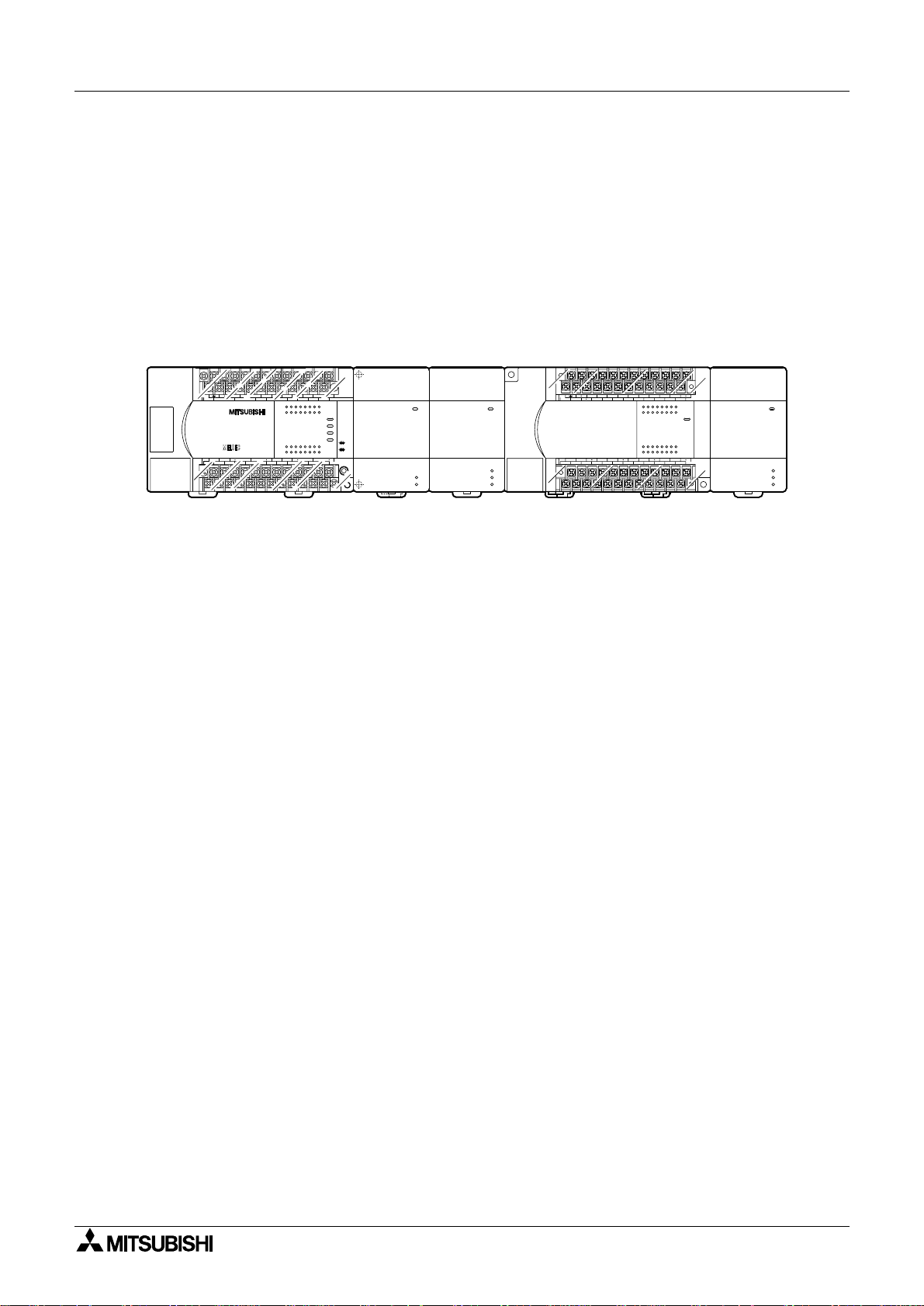
2.5 Connection to PC Main Unit
Connect the FX2N-2LC to the PC main unit with an extension cabl e.
FX
-2LC units are treated as special blocks of the PLC, and the special block No. 0 to 7 is
2N
automatically assigned to each FX
(These unit Nos. are used in FROM/TO instructions.)
One FX
For the details of I/O assignment in the PC, refer to the manual of the FX
-2LC unit occupies eight I/O points in the PC main unit.
2N
Product Configuration 2
-2LC unit from the one nearest to the PLC basic unit.
2N
Series PC.
2N/2NC
FX2N-32MR
(X000 to X017)
X3X2X1
FX2N-32MR
Y4Y5Y6
Y10
COM3
X10 X14 X16
X7
IN
OUT
Y12
Y11
Y13Y1Y2Y3
14 171510 12 13
Y14
COM X4
LX13X15
24+N
(Y000 to Y017)
72456130
1611
72456130
1611 1514 1710 12 13
Y15
FX2N-4AD
POWER
RUN
BATT.V
PROG.E
CPU.E
FX2N-4AD
Special
block
No. 0
POWER
A/D
24V
FX2N-2LC
POWER
FX2N-2LC
24V
OUT1
OUT2
Special
block
No. 1
(X020 to X037)
(Y020 to Y037)
( ) indicates the I/O No. assignment in the PC main unit.
• Up to eight FX
units can be connected to the FX
• When connecting the FX
-2LC units can be connected to the FX2N Series PC. Up to four FX2N-2LC
2N
Series PC.
2NC
-2LC unit to the FX
2N
Series PC, the interface FX
2NC
required.
(When connecting the FX
-2LC unit to the FX2N Series PC, the interface FX
2N
not required.)
FX2N-32MR
X0
X6 X0 X2 X4 X6
COM X4
24+N
X3X2X1
FX2N-32ER
X5
X7
IN
01234567
OUT
76543210
72456130
72456130
Y4Y5Y6
COM4COM2Y4Y5Y6Y7 COM3Y0Y1Y2Y3COM1Y0Y1Y2Y3
L X1X3X5X7
POWER
Y7
FX2N-2LC
POWER
FX2N-2LC
24V
OUT1
OUT2
Special
block
No.2
-CNV-IF is
2NC
-CNV-IF is
2NC
• For extension, an extension cable FX
rately are required.
Only one FX
-65EC can be used per system.
0N
-65EC (650 mm) and the FX
0N
-CNV-BC sold sepa-
2NC
2-4
Page 21

FX2N-2LC Temperature Control Block
Specifications 3
1 Introduction
2 Product Configur ation
3 Specifications 3
4 Wiring
5 Introduction of Functions
6Alarm
7 Buffer Memory (BFM)
8 Program Example
9 Diagnostic
Page 22

FX2N-2LC Temperature Control Block
Specifications 3
Page 23

FX2N-2LC Temperature Control Block
3. Specifications
3.1 Environmental specifications
Table 3.1:
Item Specifications
Withstand voltage
500 VAC for 1 minute (between analog input terminal and grounding terminal)
Specifications 3
Other environmental specifications are equivalent to those for the PC main unit. (Refer to the
manual of the PC main unit.)
3.2 Power supply specifications
Table 3.2:
Item Specifications
Driving power supply 24 VDC (-15% to +10%), input from driving power supply terminal
Power supply for communi-
cation
Current consumption 24 VDC, 55 mA and 5 VDC, 70 mA
Insulation method
Number of occupied I/O
points
5 VDC (supplied from inside of PC main unit)
Analog input area and PC are insulated by photocoupler.
Power supply and analog input ar e insula ted by DC/DC converter.
(Channels are not insulated each other.)
8 points in total (including input points and output points)
3
3-1
Page 24

FX2N-2LC Temperature Control Block
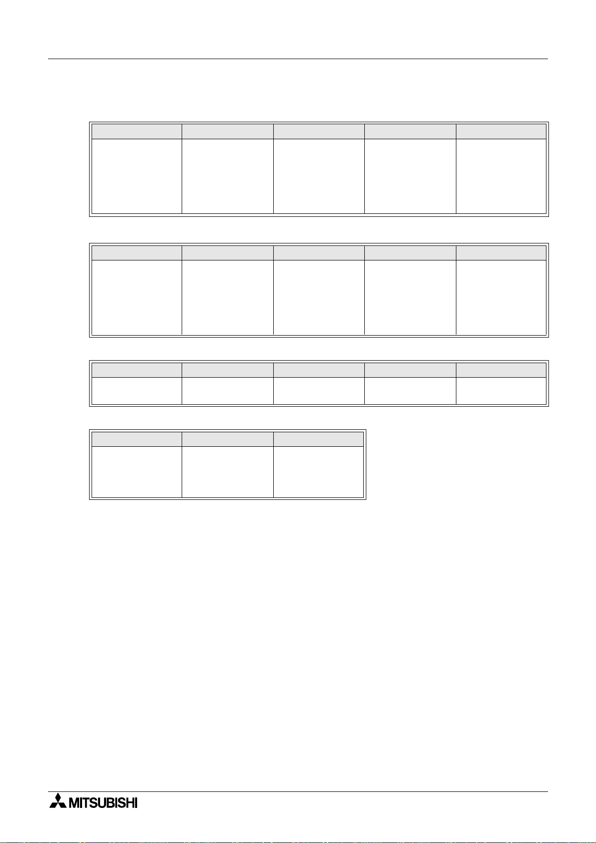
3.3 Performance specifications
Table 3.3:
Item Description
Control method
Control operation period 500 ms
Set temperature range Equivalent to input range (Refer to 7.2.33)
Heater disconnection detection
Operation mode
Self-diagnosis function
Memory Built-in EEPROM (Number of times of overwrite: 100,000 times)
POWER
24V
Status
indication
OUT1
OUT2
Lit (green) 5 V power is supplied from PC main unit.
Extinguished 5 V power is not supplied from PC main unit.
Lit (red) 24 V power is supplied from outside.
Extinguished 24 V power is not supplied from outside.
Lit (red) OUT1 output is ON.
Extinguished OUT1 output is OFF.
Lit (red) OUT2 output is ON.
Extinguished OUT2 output is OFF.
Specifications 3
Two-position control, PID control (with auto tuning function), PI
control
Alarm is detected in accordance with setting of buffer memory.
(Variable within range from 0.0 to 100.0 A.).
0: Measured value monitor
1: Measured value monitor + Temperature alarm
2: Measured value monitor + Temperature alarm + Control
(Selected by buffer memory)
Adjustment data and input value are checked by watch dog timer.
When abnormality is detected, transistor output turns off.
3-2
Page 25

FX2N-2LC Temperature Control Block
3.4 Input specifications
Table 3.4:
Item Description
Number of input points 2 points
Input type
Measurement precision
Cold contact tempera-
Temperature
input
CT input
ture compensation error
Resolution
Sampling period 500 mS
Effect of external resistance
Input impedance
Sensor current Approx. 0.3 mA
Allowable input lead wire
resistance
Operation when input is
disconnected
Operation when input is
short-circuited
Number of input points 2 points
Current detector
Heater
current
measured
value
Measurement precision
Sampling period 1 second
Thermocou-
ple
Resistance
thermome-
ter bulb
When CTL-
12 is used
When CTL-
6 is used
Specifications 3
K, J, R, S, E, T, B, N, PLII, WRe5=26, U, L
Pt100, JPt100
± 0.7 % of range span ± 1 digit
(± 0.3 % of range span ± 1 digit when ambient temperature is
23 °C ± 5 °C)
However, 0 to 399 °C (0 to 799 °F) in B inputs as well as 0 to
32 °F in PLII and WRe5-26 inputs are outside precision guarantee range.
Within ± 1.0 °C
However, within ± 2.0 °C while input value is -100 to -150 °C
within ± 3.0 °C while input value is -150 to -200 °C
0.1 °C (0.1 °F) or 1 °C (1 °F)
(Varies depending on input range of used sensors.)
Approx. 0.35 µV/
1 Μ Ω
10 Ω or less
Upscale
Downscale
CTL-12-S36-8 or CTL-6-P-H
(manufactured by U.R.D. Co., Ltd.)
0.0 to 100.0 A
0.0 to 30.0 A
Larger one between ± 5 % of input value and 2 A
(excluding precision of current detector)
or more
Ω
3
3-3
Page 26
FX2N-2LC Temperature Control Block
3.5 Input range
Table 3.5:
Sensor type K J R S
-200.0 to 200.0 °C
-100.0 to 400.0 °C
Input range
Sensor type E T B N
Input range
-100 to 1300 °C
-100 to 2400 °F
-200.0 to 200.0 °C
-100 to 800 °F
0 to 1000 °C
0 to 1800 °F
-200.0 to 200.0 °C
-100.0 to 400.0 °C
-100.0 to 800.0 °C
-100 to 1200 °C
-100 to 1600 °F
-100 to 2100 °F
-200.0 to 200.0 °C
-200.0 to 400.0 °C
0 to 400.0 °C
-300.0 to 400.0 °F
-300.0 to 700.0 °F
0.0 to 700.0 °F
0 to 1700 °C
0 to 3200 °F
0 to 1800 °C
0 to 3000 °F
Specifications 3
0 to 1700 °C
0 to 3200 °F
0 to 1300 °C
0 to 2300 °F
Sensor type PL II WRe5-26 U L
Input range
Sensor type K J
Input range
0 to 1200 °C
0 to 2300 °F
-50.0 to 150.0 °C
-200.0 to 500.0 °C
-300.0 to 300.0°F
-300 to 900 °F
0 to 2300 °C
0 to 3000 °F
-50.0 to 150.0 °C
-200.0 to 600.0 °C
-300.0 to 300.0°F
-300 to 1100 °F
-200.0 to 600.0 °C
-300.0 to 700.0 °F
0.0 to 900.0 °C
0 to 1600 °F
• When B is used, 0 to 399 °C (0 to 799 °F) is outside the precision compensation range.
• When PLII is used, 0 to 32 °F is outside the precision compensation range.
• When WRe5 to WRe26 are used, 0 to 32 °F is outside the precision compensation range.
3-4
Page 27
FX2N-2LC Temperature Control Block
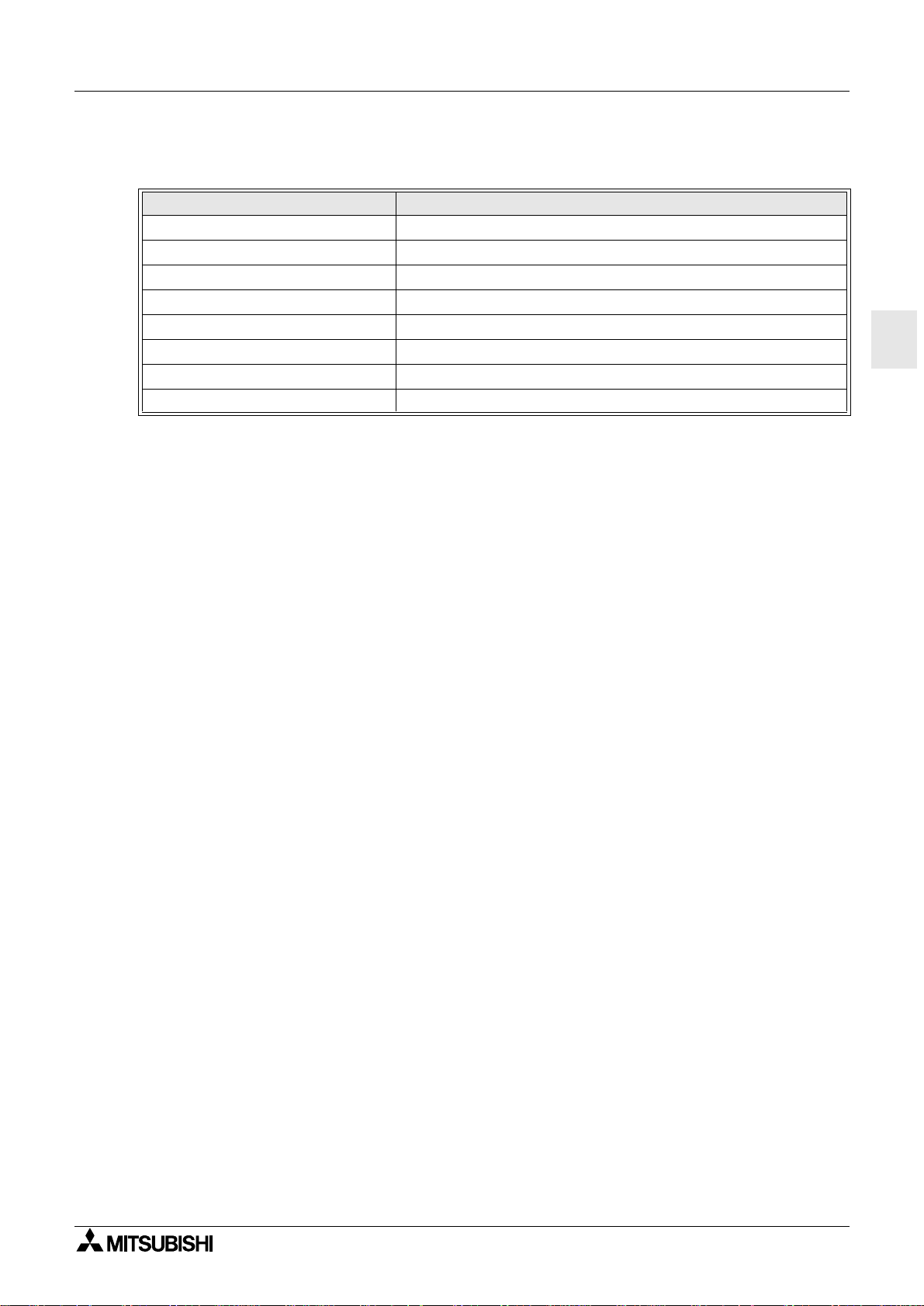
3.6 Output specifications
Table 3.6:
Item Description
Number of output points 2 points
Output method NPN open collector transistor output
Rated load voltage 5 to 24 VDC
Maximum load voltage 30 VDC or less
Maximum load current 100 mA
Leak current in OFF status 0.1 mA or less
Maximum voltage drop in ON status 2.5 V (maximum) or 1.0 V (typical) at 100 mA
Control output cycle 30 seconds (Variable within range from 1 to 100 seconds)
Specifications 3
3
3-5
Page 28

FX2N-2LC Temperature Control Block
Specifications 3
3-6
Page 29

FX2N-2LC Temperature Control Block
Wiring 4
1 Introduction
2 Product Configur ation
3 Specifications
4 Wiring 4
5 Introduction of Functions
6Alarm
7 Buffer Memory (BFM)
8 Program Example
9 Diagnostic
Page 30

FX2N-2LC Temperature Control Block
Wiring 4
Page 31

FX2N-2LC Temperature Control Block
4. Wiring
Cautions on Wiring
• Make sure to shut down the po wer supplies of all phases on the outside before starting
installation or wiring.
If the power supplies are not shut down, you may get electrical shock or the unit may be
damaged.
• As to loads which are dangerous when turning on at the same time, make sure to interlock them outside the PLC and the FX
gram in the PLC.
Wiring 4
-2LC in addition to interlocking of them in a pro-
2N
4
• Correctly connect the power cable of the FX
-2LC and the PLC as described in this
2N
manual.
If the AC po we r suppl y is connect ed to a DC I/O terminal or DC pow er terminal, the PLC
may be burnt.
• Never perform external wiring to unused terminals in the FX
-2LC and the PLC.
2N
Such wiring may damage the units.
• Per form Class 3 grounding with an electric wire of 2 mm
nal in the FX
-2LC and the PLC.
2N
2
or more to the ground ing termi-
However, never perform common grounding with a strong power system.
4-1
Page 32

FX2N-2LC Temperature Control Block
4.1 Wiring
When a temperature sensor is a thermocouple (TC)
FX2N-2LC
24+
24-
*1
OUT1
COM
OUT2
CT
CT
PTA / •
FG
PTB / TC+
PTB / TC-
CT
CT
Shielded cable
DC24V
+-
SSR
SSR
Thermocouple
Wiring 4
AC power supply
CT
Heater
CT
PTA / •
FG
PTB / TC+
PTB / TC-
Shielded cable
Thermocouple
Heater
When a temperature sensor is a resistance thermometer bulb (RTD)
Resistance
2N
FX
-2LC
PTA / •
FG
PTB / TC+
PTB / TC-
Shielded cable
*1 Connect the terminal in the FX
thermometer
bulb
-2LC to the terminal in the PLC to which Class
2N
3 grounding is performed.
• When using a thermocouple, use specified compensating lead wires.
• When using a resistance thermometer bulb, use the three-wire type, and perform wiring
with lead wires having small resistance and no diffe rence in the resistance among the three
wires.
• Terminal tightening torque: 0.5 to 0.8 N·m
4-2
Page 33

FX2N-2LC Temperature Control Block
Introduction of Functions 5
1 Introduction
2 Product Configur ation
3 Specifications
4 Wiring
5 Introduction of Functions 5
6Alarm
7 Buffer Memory (BFM)
8 Program Example
9 Diagnostic
Page 34

FX2N-2LC Temperature Control Block
Introduction of Functions 5
Page 35

FX2N-2LC Temperature Control Block
5. Introduction of Functions
This section introduces the functions of the FX2N-2LC.
For setting of each function, refer to the description on buffer memories (BFM) later.
5.1 PID control
5.1.1 Easy PID control with two degrees of freedom
PID control is a control method to obtain stable control result by setting each of the constants
"P (proportional band)", "I (integral time)" and "D (derivative time)".
However, if each PID constant is so set that the "response to setting" becomes good, the
"response to disturbance" becomes deteri orated in PID control. On the c ontrar y, if each PID
constant is so set that the "response to disturbance" becomes good, the "response to setting"
becomes deteriorated.
Introduction of Functions 5
The FX
-2LC performs easy PID control with two degrees of freedom in which PID constants
2N
realizing good response to di sturbance are adopted and the shape of the "response to setting"
can be selected as either "fast", "medium" or "slow".
Setting of PID constants and selection of the "response to setting" can be p erformed using
buffer memories.
Conventional PID control
When PID constants are set so that the response to changes in set value becomes good
Response to changes in set value Response to disturbance
Set value
(SV)
When PID constants are so set that the response to disturbance becomes good
Response to changes in set value Response to disturbance
Set value
(SV)
Set value
(SV)
Set value
(SV)
5
Easy PID control with two degrees of freedom
Response to changes in set value Response to disturbance
Fast
Medium
Set value
(SV)
Slow
Set value
(SV)
5-1
Page 36

FX2N-2LC Temperature Control Block
5.1.2 Overshoot prevention function
Generally in PID control, when a deviation continues for a long time, the PID arithmetic operation result exceeds the effective range (from 0 to 100%) of the operation quantity. At this time,
even if the deviation becomes smaller, it takes some time until the output comes within the
effective range because of the integ ral oper ati on. As a result , executio n of an actual cor recti on
operation is delayed, and overshoot/undershoot occurs.
In order to prevent overshoot, the FX
function. The RFB limiter function feeds back the excessive quantity to the integral value and
makes the arithmetic operation result be held at the limit point when the PID arithmetic operation result exceeds the limit point (upper/lower limit of the output limiter) so that the PID arithmetic operation result al wa y s remains insi de the effective r ange . Accordingl y, when a deviatio n
becomes small, the correction operation is immediately performed.
Introduction of Functions 5
-2LC is equipped with the RFB (reset-feedback) limiter
2N
<When the RFB limiter function is not provided>
Operation
quantity (%)
Output limiter upper limit
Output limiter lower limit
Temperature
Target
value
Large overshoot
<When the RFB limiter function is provided>
The excessive quantity above the output limiter
upper limit is fed back to the integral value, and
the arithmetic operat ion result is held at the
upper limit value.
Operation
quantity (%)
Output limiter upper limit
Output limiter lower limit
Temperature
Target
value
5-2
Page 37

FX2N-2LC Temperature Control Block
5.2 Two-position control
When the proportional band (P) value is set to "0.0", the FX2N-2LC performs two-position control.
In two-position control, the control output (MV) is set to ON when the measured value (PV) is
larger than the temperature set value (SV) or OFF when the measured value (PV) is smaller
than the temperature set val ue (SV).
When the adjustment sen sitivity (dead zone) is set, repetitious tu r ning ON/OFF of the ou tput
around the temperature set value (SV) can be prevented.
However, if the adjustment sensitivity (dead zone) is set to a large value, upward/downward
fluctuation becomes large ac cordingly. If the adjustment sensitivity (dead zone ) is set to a
small value, chattering (drastic repetitious turning ON/OFF) may be caused by small oscillations of measured values.
Introduction of Functions 5
Temperature
set value (SV)
Operation output
value (MV)
ON OFF ON OFF
5
Adjustment sensitivity (dead zone)
* The adjustment sensitivity is equally given
to the upper portion and t he lower portion
of the temperature set value (SV).
Time
5-3
Page 38

FX2N-2LC Temperature Control Block
5.3 Auto tuning function
5.3.1 AT (auto tuning)
The AT (auto tuning) function automatically measures, calculates and sets optimal PID constants in accordance with the set temperature.
When the AT execution command (CH1: BFM #20, CH2: BFM #29) is set to "1", auto tuning is
performed. (Auto tuning can start from an arbitrary status at any time immediately after the
power is turned on, while the temperature is rising or while control is stable.)
When auto tuning starts, two-position control is p erformed using the set value (SV). B y twoposition control, the output is forcedly hunted and its amplitude and oscillation cycle are measured. PID constants are calculated based on the measured values, and stored in each
parameter. When auto tuning normally finishes, control continues with new calculated PID
constants.
While auto tuning is performed, b14 of the event (CH1: BFM #1, CH2: BFM #2) is set to "1".
For auto tuni ng, the AT bias can be set.
(In order to calculate proper PID constants by auto tuning, set the upper limit of the output limiter to 100%, the lower l imit of the output l imiter to 0%, and the output chang e r atio limi ter function to OFF.)
Introduction of Functions 5
1) Auto tuning can be performed when the following conditions are satisfied.
- The control start/stop status shall be set to "control start".
- The operation mode shall be set to the control "mode 2".
- The auto/manual mode shall be set to "auto".
- The input value (PV) shall be normal.
- The upper limit and the lower limit of the output limiter shall not be set to a same value.
- The proportional band shall not be set to "0 (two-position operation)".
5-4
Page 39

FX2N-2LC Temperature Control Block
2) When either of the following conditions are given during auto tuning, the operation is
aborted.
- When the input value (PV) becomes abnormal caused by disconnection, etc.
- When the set value (SV) is changed
- When control is stopped, when the operation mode is changed or when the auto/manual
mode is set to "manual"
- When the AT bias setting is changed
- When the PV bias setting is changed
- When the digital filter setting is changed
- When the output limiter setting is changed
- When the power is interrupted
- When the AT execution command (CH1: BFM #20, CH2: BFM #29) is set to "0 (AT stop)"
Measured value (PV)
Introduction of Functions 5
(Example: When AT is performed while the temperature is rising)
5
5.3.2 AT bias
Set the AT bias to perform auto tuning in which the measured v al ue (PV) should not exceed the
temperature set value (SV).
The auto tuning fu nction p erforms two-p osition co ntrol using the temperature set value (SV) ,
hunts the measured value (PV), then calculates and sets each PID constant. However, for
some control targets, overshoot caused by hunting is not desirable. Set the AT bias for such a
case. When the AT bias is set, the set value (SV) (AT point) with which auto tuning is performed can be changed.
Temperature
set value (SV)
Temperature
set value (SV)
Measured value (PV)
AT point
AT starts.
Example: When the AT bias is set to "-"
AT finishes.
Time
AT bias
AT starts.
AT finishes.
Time
5-5
Page 40

FX2N-2LC Temperature Control Block
5.4 Auto / manual
5.4.1 Auto mode and manual mode
The mode can be changed over between "auto" and "manual". In the auto mode, the control
output value (MV) is set to the output quantity automatically calculated in accordance with the
temperature set value (SV). In the manual mode, the control output value (MV) is set to the
output quantity set arbitrarily and manually.
In the manual mode, b13 (manual mode transition completion) of the event (CH1: BFM #1,
CH2: BFM #2) becomes "1" to notify the manual mode.
0.5 second is required to change over the mode. During changeover, the balance-less, bump-
less function is actuated.
Auto mode
In the auto mode, the measured value (PV) is compared with the temperature set value (SV),
and the control output (MV) is given by PID arithmetic operation.
This mode is selected when the FX
In the auto mode, the manual output value is always set to the output value (MV).
-2LC is shipped.
2N
Introduction of Functions 5
Manual mode
In the manual mode, the output (MV) value is fixed to a certain value.
By changing the manual output setting (BFM #19, BFM #28), the output value can be fixed to
an arbitrary value.
The manual output value can be changed while b13 of the e v ent (CH1: BFM #1, CH2: BFM #2)
is "1" (that is, when the manual mode is sel ected).
Even in the manual mode, the temperature alarm function is effective.
5-6
Page 41

FX2N-2LC Temperature Control Block
5.4.2 Balance-less, bump-less function
The balance-less, bump-less function prevents overload caused by drastic change in the control output value (MV) when the mode is changed over from auto to manual (or from manual to
auto).
Operation performed when the mode is changed o ver from auto to manual:
The control output value in the auto mode continues to be effective.
Operation performed when the mode is changed over from manual to auto:
The control output value is changed over to a value automatically calculated
based on the temperature set value (SV).
Operation output quantity
Auto Manual Auto
Introduction of Functions 5
5
Time
➀ ➁➂
➀
The mode is changed over from auto to manual. However, the operation output quantity
follows the operation output quantity in the auto mode.
➁
The operation output quantity is manually changed.
➂
The mode is changed over from manual to auto. The operation output quantity becomes
a value automatically calculated based on the temperature set value (SV).
5-7
Page 42

FX2N-2LC Temperature Control Block
5.5 Heater disconnection detection function
The heater disconnection detection function detects the current flowing in the load using a current detector (CT), it compares the detected value (heater current measured value) with the
current value set for heater disconnection alarm , and issues an alar m when the mea sured
value is more than or less than the current set value for the heater disconnection alarm.
The heater current can be measured using buffer memories (BFM #7, BFM #8).
Connection example
Power supply
Temperature
control block
-2LC
FX
2N
Control output
Current detector
Operating
machine SSR
Introduction of Functions 5
Current detector input
Heater
Measured
value (PV)
Sensor
Control target
Alarm operation
The heater disconnection detection function issues an alarm in the following cases.
When the heater current does not flow
1)
... Caused by heater disconnecti on, error in operating machine, etc.
When the reference heater current value is equivalent to or less than the current set value
for the heater disconnection alarm while the control output is ON, an alarm is issued.
However, if the control output ON time is 0.5 sec or less, heater disconnection alarm is not
issued.
When the heater current does not turn off
2)
... Caused by a molten relay, etc.
When the reference heater curr ent value is m ore th an th e curre nt set value for the hea ter
disconnection alarm while the control output is OFF, an alarm is issued.
However, if the control output OFF time is 0.5 sec or less, heater disconnection alarm is not
issued.
Current detector
CTL-12-S36-8 (Applicable current range: 0.0 to 100.0 A)
CTL-6-P-H (Applicable current range: 0.0 to 30.0 A)
Manufacturer: U.R.D. Co., Ltd.
5-8
Page 43

FX2N-2LC Temperature Control Block
5.6 Loop breaking alarm function (LBA)
The loop breaking alarm function starts to detect the variation of the measured value (PV), at
every loop breaking alar m judgment time w hen the output be comes more tha n 100% (or the
output limiter upper limit) or less than 0% (or the output limiter lower limit), then sets to ON the
loop breaking alarm (CH1: BFM #1 b8, CH2: BFM #2 b8) when judging that there is an abnormality in the control loop.
Abnormality judgment criteria
Table 5.1: Heating control (rever se operation)
When output is less than 0% or
output li miter lower limit
When output is more than 100%
or output limiter upper limit
When measured value (PV) does not decrease at least by loop
breaking change criteria (2 °C) within loop breaking set time, an
alarm is issued.
When measured value (PV) does not increase at least by loop breaking change criteria (2 °C) within loop breaking set time, an alarm is
issued.
Introduction of Functions 5
Table 5.2: Cooling control (normal operation)
When output is less than 0% or
output li miter lower limit
When output is more than 100%
or output limiter upper limit
When measured value (PV) does not decrease at leas by loop breaking change criteria (2 °C) within loop breaking set time, an alarm is
issued.
When measured value (PV) does not increase at least by loop breaking change criteria (2 °C) within loop breaking set time, an alarm is
issued.
Abnormality targets
1) Abnormality in control target: Heater disconnection, lack of power supply, wiring mistake,
etc.
2) Abnormality in sensor: Sensor disconnection, short-circuit, etc.
3) Abnormality in operating machine: Molten relay, wiring mistake, etc.
4) Abnormality in output circuit: Molten relay inside instrument, etc.
5) Abnormality in input circuit: No change in the measured value (PV) even after input has
changed
Note:
- When the auto tuning function is used, the LBA set time is automatically set to the inte-
gral time result multiplied by 2.
The LBA set time does not change even if the integral v alue changes.
5
- While auto tuning is performed, the loop breaking alarm function is disabled.
- If the LBA set time is too short or is not suitable to control targets, the loop breaking
alarm may repeatedly turn on and off or may not turn on.
In such a case, change the LBA set time in accordance with the situation.
- The loop breaking alarm function judges abnormalities in the control loop, but cannot
detect positions in which abnormalities occur.
Check each part of the control system in turn.
5-9
Page 44

FX2N-2LC Temperature Control Block
Introduction of Functions 5
5-10
Page 45

FX2N-2LC Temperature Control Block
1 Introduction
2 Product Configur ation
3 Specifications
4 Wiring
5 Introduction of Functions
Alarm 6
6 Alarm 6
7 Buffer Memory (BFM)
8 Program Example
9 Diagnostic
Page 46

FX2N-2LC Temperature Control Block
Alarm 6
Page 47

FX2N-2LC Temperature Control Block
6. Alarm
The FX2N-2LC is equipped with 14 types of alarms. Among them, up to 4 ty pes can b e used in
accordance with the application.
The alarm types to be used can be selected using buffer memories. The result of each alarm
is written to BFM #1 and BFM #2, and can be read in the PLC main unit.
When the measured value (PV) is near th e alar m set value of an use d alar m typ e, the alar m
status and the non-alarm status may be repeated by fluctuation in inputs. In or der to c ope with
such a case, the alarm dead zone can be set to prevent repeating of the alarm status and the
non-alarm status. (The dead zone of alarms 1 to 4 can be set using BFM #76.)
Table 6.1:
Alarm
No.
0 Alarm function OFF Alarm function is disabled. --1 Upper limit input value alarm
2 Lower limit input value alarm
3 Upper limit deviation alarm
4 Lower limit deviation alarm
5 Upper/lower limit deviation
6 Range alarm
Upper limit input value alarm
7
with wait
Lower limit input value alarm
8
with wait
Upper limit deviation value
9
alarm with wait
Lower limit deviation val ue
10
alarm with wait
Upper/lower limit deviation
11
value alarm with wait
Alarm type Description
When measured value (PV) is more than alarm set
value, an alarm is issued.
When measured value (PV) is less than alarm set
value, an alarm is issued.
When deviation (= Measured value (PV) - Set
value (SV)) is more than alarm set value, an alarm
is issued.
When deviation (= Measured value (PV) - Set
value (SV)) is less than alarm set value, an alarm
is issued.
When absolute deviation (= Measured value (PV)
- Set value (SV)) is more than alarm set value, an
alarm is issued.
When absolute deviation (= Measured value (PV)
- Set value (SV)) is less than alarm set value, an
alarm is issued.
When measured value (PV) is more than alarm set
value , an alarm is issued . How ev er, when power is
turned on, measured value is ignored.
When measured value (PV) is less than alarm set
value , an alarm is issued . How ev er, when power is
turned on, measured value is ignored.
When deviation (= Measured value (PV) - Set
value (SV)) is more than alarm set value, an alarm
is issued. However, when power is turned on,
measured value is ignored.
When deviation (= Measured value (PV) - Set
value (SV)) is less than alarm set value, an alarm
is issued. However, when power is turned on,
measured value ignored.
When absolute deviation (= Measured value (PV)
- Set value (SV)) is more than alarm set value, an
alarm is issued. However, when power is turned
on, measured value is ignored.
Alarm 6
Set
range
Input
range
Input
range
±Input
width
±Input
width
+Input
width
+Input
width
Input
range
Input
range
±Input
width
±Input
width
+Input
width
6
6-1
Page 48

FX2N-2LC Temperature Control Block
Table 6.1:
Alarm
No.
12
13
14
Upper limit deviation value
alarm with re-wait
Lower limit deviation val ue
alarm with re-wait
Upper/lower limit deviation
value alarm with re-wait
Alarm type Description
Input range:Numeric value from the lower limit to the upper limit of input value
When deviation (= Measured value (PV) - Set
value (SV)) is more than alarm set value, an alarm
is issued. However, when power is turned on and
when set value is changed, measured value is
ignored.
When deviation (= Measured value (PV) - Set
value (SV)) is less than alarm set value, an alarm
is issued. However, when power is turned on and
when set value is changed, measured value is
ignored.
When absolute deviation (= Measured value (PV)
- Set value (SV)) is more than alarm set value, an
alarm is issued. However, when power is turned
on and when set value is changed, measured
value is ignored.
Alarm 6
Set
range
±Input
width
±Input
width
+Input
width
Input width:Width from the lo wer limit to the upper limit of input value (Input width = Upper limit
value - Low er limit value)
± Input width ...Both a positive and negative numeric values can be set.
+ Input width ...Only a positive numeric value can be set.
6-2
Page 49

FX2N-2LC Temperature Control Block
Upper limit input value alarm
When the measured value (PV) is more than the alarm set value, an alarm is issued.
Alarm 6
Measured value (PV)
Alarm set value
Alarm status
Measured value (PV)
Time
Non-alarm status
Alarm status
Lower limit input value alarm
When the measured value (PV) is less than th e alarm set va lue, an alarm is issued.
Measured value (PV)
Measured value (PV)
Alarm set value
Time
Alarm status
Non-alarm status
Alarm status
6
Upper limit deviation alarm
When the deviation ( = Measured value (PV) - Set value (SV)) i s more than the al arm set val ue ,
an alarm is issued.
Measured value
Alarm set
value
Temperature
set value (SV)
Alarm status
< When the deviation is positive >
(PV)
Measured value
(PV)
Devia
tion
Time
Temperature
set value (SV)
Alarm status
< When the deviation is negative >
Measured value
(PV)
Alarm set
value
Measured value
Non-alarm
status
(PV)
Devia
tion
Time
Alarm
status
6-3
Page 50

FX2N-2LC Temperature Control Block
Lower limit deviation alarm
When the deviation (= Measured value (PV) - Set value (SV)) is less than the alarm set value,
an alarm is issued.
Alarm 6
< When the deviation is positive >
Measured value
(PV)
Alarm set
value
Temperature
set value (SV)
Alarm status
Measured value
(PV)
Devia
tion
Time
Temperature
set value (SV)
Alarm set value
Alarm status
Upper/lower limit deviation alarm
When the absolute deviation (=
Measured value (PV) - Set value (SV)) is more than the
alarm set value, an alarm is issued.
For example, if the alarm set value is "+10
°
C", an alarm is issued when the measured value
(PV) is outside the range from "set value (SV) + 10
Measured value (PV)
Alarm set
value
Temperature
set value (SV)
Alarm set
value
Measured value (PV)
< When the deviation is negative >
Measured value
(PV)
°
C" to "set value (SV) - 10 °C".
Deviation
Deviation
Measured value
(PV)
Non-alarm
status
Devia
tion
Time
Alarm
status
Alarm status
Range alarm
When the absolute deviat ion (=
Measured value (PV) - Set value (SV)) is less than the alarm
set value, an alarm is issued.
For example, if the alarm set value is "+10
°
C", an alarm is issued when the measured value
(PV) is inside the range from "s et value (SV) + 10
Measured value (PV)
Measured value (PV)
Alarm set
value
Temperature
set value (SV)
Alarm set
value
Alarm status
Time
°
C" to "set value (SV) - 10 °C".
Deviation
Deviation
Time
Non-alarm status
Alarm status
Non-alarm status
Alarm status
6-4
Page 51

FX2N-2LC Temperature Control Block
Alarm wait operation
The wait operation ignores the alarm status of the measured value (PV) occurred when the
power is turned on, and disables the alarm function until the measured value (PV) goes out of
the alarm status once.
When control starts, the wait operation is performed also.
Alarm 6
< When the wait operation is performed >
Measured value (PV)
Temperature
set value (SV)
Alarm set
value
Wait operation region
Alarm status
Measured value
(PV)
Devia
tion
Time
< When the wait operation is not performed >
Measured value (PV)
Temperature
set value (SV)
Alarm set
value
Alarm status
Non-alarm
status
Measured value
(PV)
Devia
tion
Time
Alarm
status
Alarm re-wait operation
The alarm re-wait operation ignores the alar m status of the mea sured value (PV) occurred
when the power is turned on, and disables the alarm function until the measured value (PV)
goes out of the alarm status once.
When the temperature set value (SV) is changed, the measured value (PV) for deviation alarm
changes accordingly. At this time, even if the measured value (PV) becomes the alarm status,
the alarm re-wait function ignores it again and disables the alarm function until the measured
value (PV) goes out of the alarm status again.
6
Re-wait operation
Measured value (PV)
Temperature set
value (SV)
Alarm set value
Temperature set
value (SV1)
Alarm set value
Alarm status
Set value is changed.
Wait operation region
Measured value (PV)
Wait operation region
Deviation
Deviation
Time
Non-alarm
status
Alarm status
6-5
Page 52

FX2N-2LC Temperature Control Block
Alarm 6
6-6
Page 53

FX2N-2LC Temperature Control Block
1 Introduction
2 Product Configuration
3 Specifications
4 Wiring
5 Introduction of Functions
Buffer Memory (BFM) 7
6Alarm
7 Buffer Memory (BFM) 7
8 Program Example
9 Diagnostic
Page 54

FX2N-2LC Temperature Control Block
Buffer Memory (BFM) 7
Page 55

FX2N-2LC Temperature Control Block
7. Buffer Memory (BFM)
Each setting and alarm in the FX2N-2LC is written from or read to the PLC main unit through
buffer memories (hereafter referred to as "BFM").
Each BFM consists of 16 bits. Use FROM/TO instructions in the 16-bit format.
7.1 Buffer memory list
Table 7.1:
BFM No.
CH1 CH2
#0 Flag Error flag, ready flag, etc. 0
#1 #2 Event
#3 #4 Measured value (PV) ±5% of input range (°C/°F) 0.0
#5 #6 Control output value (MV) -5.0 to 105.0 (%) -5.0
#7 #8 Heater current measured value 0.0 to 105.0 (A) 0.0
#9 Initialization command
#10 Error reset command
#11 Control start/stop changeover
#12 #21 Set value (SV) Within set range limiter 0.0
#13 #22 Alarm 1 set value
#14 #23 Alarm 2 set value 0.0
#15 #24 Alarm 3 set value 0.0
#16 #25 Alarm 4 set value 0.0
#17 #26
#18 #27 Auto/manual mode changeover 0:AUTO 1:MAN 0
#19 #28 Manual output set value -5.0 to 105.0 (%) *1 0.0
#20 #29 Auto tuning execution command
#30 Unit type code 2060 R
#31 Prohibited --- --- ---
#32 #51 Operation mode
#33 #52 Proportional band
#34 #53 Integral time 1 to 3,600 sec 240
#35 #54 Derivative time 0 to 3,600 sec 60
Heater disconnection alarm set
value
Name Description/set range
Buffer Memory (BFM) 7
Alarm status, temperature rise
completed status, etc.
0: Performs nothing
1: Initializes all data
2: Initializes BFM #10 to BFM #69
0: Performs nothing
1: Resets errors
0: Stops control
1: Starts control
Unit: °C or °F
Allowable set range varies
depending on alarm mode setting.
0.0 to 100.0 A
(When "0.0" is set, alarm function
is disabled.)
0: Stops auto tuning
1: Performs auto tuning
0: Monitor
1: Monitor + Temperature alarm
2: Monitor + Temperature alarm +
Control
0.0 to 1,000.0 %/span
(When "0.0" is set, two-position
control is performed.)
Initial
value
0.0
0.0
3.0
Remarks
0
0
0
0
R/W
0
2
R/W
R
---
7
✩
---
✩
7-1
Page 56

FX2N-2LC Temperature Control Block
Table 7.1:
BFM No.
CH1 CH2
#36 #55 Control response parameter 0: Slow 1: Medium 2: Fast 0
#37 #56 Output limiter upper limit
#38 #57 Output limiter lower limit -5.0% to output limiter upper limit 0.0
#39 #58 Output change ratio limiter
#40 #59
#41 #60
#42 #61 Control output cycle setting 1 to 100 sec 30
#43 #62 Primary delay digital filter setting
#44 #63 Setting change ratio limiter
#45 #64 AT (auto tuning) bias ±Input span (°C/°F) 0.0
#46 #65
#47 #66 Setting limiter upper limit
#48 #67 Setting limiter lower limit
#49 #68
#50 #69 Loop breaking alarm dead zone 0.0 or 0 to input span (°C/°F) 0.0
#70 #71 Input type selection 0 to 43 2
#72 Alarm 1 mode setting
#73 Alarm 2 mode setting 0
#74 Alarm 3 mode setting 0
#75 Alarm 4 mode setting 0
#76 Alarm 1/2/3/4 dead zone setting 0.0 to 10.0 (% / span) 1.0
#77
#78
#79
#80
Sensor correction value setting
(PV bias)
Adjustment sensitivity (dead
zone) setting
Normal/reverse operation selection
Loop breaking alarm judgement
time
Number of times of alarm 1/2/3/4
delay
Number of times of heater disconnection alarm delay
Temperature rise completion
range setting
Temperature rise completion
soak time
Name Description/set range
Output limiter lower limit to 105.0
(%)
0.0 to 100.0 %/sec
(When "0.0" is set, function is disabled.)
±50.00 (% / span) 0.00
0.0 to 10.0 (% / span) 1.0
0 to 100 sec
(When "0" is set, function is disabled.)
0.0 to 100.0 %/min
(When "0.0" is set, function is disabled.)
0: Normal operation
1: Reverse operation
Setting limiter lower limit to input
range upper limit
Input range lower limit to setting
limiter upper limit
0 to 7,200 sec
(When "0" is set, alarm function is
disabled.)
0 to 14
0 to 255 times 0
3 to 255 times 3
1 to 10 (°C/°F) 1.0
0 to 3600 (sec) 0
Buffer Memory (BFM) 7
Initial
value
100.0
1300
0.0
0.0
-100
480
Remarks
0
1
R/W
0
✩
7-2
Page 57

FX2N-2LC Temperature Control Block
Table 7.1:
BFM No.
CH1 CH2
#81 CT monitor method changeover
#82 Set value range error address
#83 Set value backup command
R : Only read is enabled.
R/W: Both read and write are enabled.
: Setting data can be backed up by EEPROM in accor dance wit h the setting of BFM #83.
✩
*1 : Write is enabled when the manual mode transition completion flag is ON.
Name Description/set range
0: Monitors both ON current and
OFF current.
1: Monitors only ON current.
0: Normal
1 or another numeric value : Setting error address
0: Normal
1: Starts to write EEPROM.
Buffer Memory (BFM) 7
Initial
value
Remarks
0R/W
0R
0R/W
✩
- As to a numeric value containing a decima l point and n umber s af ter tha t, set it as a value
multiplied by 10.
Example: 100.0 (actual value)
→→→→
1000 (set value)
- If a value is written by mistake to a buffer memory used only for read, the written value is
ignored. And 500 ms later, the buffer me mory is overwritten with a correct value.
- If a value outside the allowable set rang e is written to a buffer memory used both f or read
and write, the set value range error (b1) of the flag (BFM #0) turns on.
And the buff er memory in which the set v alu e range er ror has occu rred is control led wit h
the upper limit or the low er limit of the allowable set range.
7
7-3
Page 58

FX2N-2LC Temperature Control Block
7.2 Details of buffer memories
7.2.1 BFM #0: Flag
Table 7.2:
Bit No. Description Operation
b0 Error present
b1 Set value range error Turns on when data outside set range is written.
b2 24 VDC power supply error
b3 Set value backup error
b4 Not used --b5 Not used --b6 Not used --b7 Not used ---
Sum check error for adjustment
b8
data error
Cold contact temperature com-
b9
pensation data error
b10 A/D converted value error
b11 Not used --b12 Controlling flag Turns on when FX
b13 Set value being backed up
b14 Initialization completion flag Turns on when initialization is completed.
b15 Temperature control ready flag Turns on when FX
Buffer Memory (BFM) 7
Turns on when an error among b1 to b10 below has
occurred.
Turns on when driving power supply (24 VDC) is not supplied.
Turns on when an error has been caused by noise or when
a failure has occurred in FX
2N
-2LC.
If contents of error are not eliminated even after power is
turned off once then on again, contact Mitsubishi Electric
System Service.
Turns on when an error has been caused by noise or when
a failure has occurred in FX
2N
-2LC.
If contents of error are not eliminated even after power is
turned off once then on again, contact Mitsubishi Electric
System Service.
-2LC is performing control.
2N
Remains ON while set values are being backed up.
Refer to 7.2.42.
-2LC becomes ready for operation.
2N
Operation of b15 (Temperature control ready flag)
Temperature control ready flag
Power is turned on.
It takes 500 ms
maximum.
Initialization of temperature
control CPU is completed.
Description on operation
1) When the power is turned on and initialization of the te mperature control CPU is completed, the temperature control ready flag turns on.
2) While the temperature control ready flag is ON, the FX
-2LC accepts TO inst ructions.
2N
7-4
Page 59

FX2N-2LC Temperature Control Block
7.2.2 BFM #1 (CH1) and BFM #2 (CH2): Event
BFM #1 corresponds to CH1. BFM #2 corresponds to CH2. Assignment is equivalent
between BFM #1 and BFM #2.
Table 7.3:
Bit No. Assignment Description
b0 Input error (upper limit) Turns on when input value is over scale.
b1 Input error (lower limit) Turns on when input value is under scale.
Cold contact temperature com-
b2
pensation data error
b3 A/D converted value error
b4 Alarm 1 Turns on when an alarm has occurred.
b5 Alarm 2 Turns on when an alarm has occurred.
b6 Alarm 3 Turns on when an alarm has occurred.
b7 Alarm 4 Turns on when an alarm has occurred.
b8 Loop breaking alarm Turns on when a loop breaking alarm has occurred
b9 Heater disconnection alarm Turns on when a heater disconnection alarm has occurred.
b10 Heater meltdown alarm Turns on when a heater meltdown alarm has occurred.
b11 Not used ---
Decimal point position
b12
b13
b14
b15
(0: Unit = 1°C/°F, 1: Unit = 0.
1°C/°F)
Manual mode transition completed
AT (auto tuning) being performed
Temperature rise completed
status
Turns on when an error has been caused by noise or when
a failure has occurred in FX
If contents of error are not eliminated even after power is
turned off once then on again, contact Mitsubishi Electric
System Service.
Turns on when input range is set to "0. 1°C/°F".
Turns on when transition to manual mode is completed.
Only while b13 is ON, manual output set value can be written.
Remains ON while auto tuning is being performed.
Turns on after soak time (BFM #80) is finished within tem-
perature rise completion range (BFM #79).
2N
Buffer Memory (BFM) 7
-2LC.
7
7-5
Page 60

FX2N-2LC Temperature Control Block
Operation of b15 (temperature rise completed status)
Example 1: When the soak time is set to "0"
Set value (SV)
Temperature
rise completed
Example 2: When the soak time is set to any positive value
Set value (SV)
Buffer Memory (BFM) 7
Temperature rise
completion range
Temperature rise
completion range
Temperature
rise completed
Soak
time
Soak
time
This bit notifies that the measured value (BFM #3, BFM #4) reaches near the set value (BFM
#12, BFM #21).
When the measured value reaches the temperature rise completion range (BFM #79) and the
soak time (BFM #80) is finished, b15 of the event (BFM #1, BFM #2) turns on.
7-6
Page 61

FX2N-2LC Temperature Control Block
7.2.3 BFM #3 (CH1) and BFM #4 (CH2): Measured value (PV)
BFM #3 stores the measured value of CH1. BFM #4 stores the measured value of CH2.
The unit is
°
C, 0 . 1°C, °F or 0.1°F in accordance with the setting of the input type selection
(BFM #70, BFM #71).
7.2.4 BFM #5 (CH1) and BFM #6 (CH2): Control output value (MV)
BFM #5 stores the control output value (output ON ratio) of CH1. BFM #6 store s the control
output value (output ON ratio) of CH2.
The display range is from -5.0 to +105.0%.
7.2.5 BFM #7 (CH1) and BFM #8 (CH2): Heater current measured value
BFM #7 stores the heater curren t measure d value of CH1 inp ut from CT. BFM #8 stores the
heater current measured value of CH2 input from CT.
The display range is from 0.0 to +105.0 A.
Buffer Memory (BFM) 7
7.2.6 BFM #9: Default setting command
In BFM #9, initialize the set values.
When BFM #9 is set to "K0 (initial value) ", the default setting command is disabled.
When BFM #9 is set to "K1", addresses 10 to 81 are set to the initial values.
When BFM #9 is set to "K2", addresses 10 to 69 are set to the initial values.
However, the initial value of the setting limiter upper/lower limit is the input range upper/lower
limit.
It takes 500 ms maximum to perform initialization.
While initialization is being performed, FROM/TO ins tructions are not accepted.
7.2.7 BFM #10: Error reset command
In BFM #10, reset errors.
When BFM #10 is set to "K1", all errors occurred in BFM #0 are reset.
If the causes of an error are not eliminated, the corresponding error bit turns on again.
7.2.8 BFM #11: Control start/stop changeover
When BFM #11 is set to "K0 (initial value)", control stops.
When BFM #11 is set to "K1", control starts.
When the PLC basic unit is changed over from "RUN" to "STOP", outputs of the FX
held.
In order to stop outputs of the FX
-2LC, make sure to use BFM #11.
2N
-2LC are
2N
7
7-7
Page 62

FX2N-2LC Temperature Control Block
Buffer Memory (BFM) 7
7.2.9 BFM #12 (CH1) and BFM #21 (CH2) : Set value (SV)
BFM #12 stores the set value of CH1. BFM #21 stores the set value of CH2.
The unit is
°
C, 0 . 1°C, °F or 0.1°F in accordance with the setting of the input type selection
(BFM #70, BFM #71).
The allowable set range is the selected input range.
When the setting limiter (CH 1: BFM #47 and BFM #48, CH2: BFM #66 and BFM #6 7) is set,
the allowable set range corresponds to the setting limiter.
7.2.10 BFM #13 to BFM #16 (CH1) and BFM #22 to BFM #25 (CH2): Alarm 1/2/3/4 set value
In BFM #13 to BFM #16 and BFM #22 to BFM #25, write the set value of each alarm selected
by the alarm 1/2/3/4 mode setting (BFM #72 to BFM #75).
In the alarm 1/2/3/4 mode setting, four among 14 alarm types can be arbitrarily selected.
BFM #13 to BFM #16 (CH1) and BFM #22 to BFM #25 (CH2) are assigned to the alarm 1
mode, the alarm 2 mode, the alarm 3 mode and the alarm 4 mode respectively in the ascending order of BFM No. for each channel.
The unit and the allowable range of the set value written to BFM #13 to BFM #16 (CH1) and
BFM #22 to BFM #25 (CH2) vary depending on the selected alarm mode. In accordance with
the setting of the alarm mode setting (BFM #72 to BFM #75), write a proper set value.
7.2.11 BFM #17 (CH1) and BFM #26 (CH2): Heater disconnection alarm set value
In BFM #17, set a value to recognize heater disconnection in CH1. In BFM #26, set a val ue to
recognize heater disconnect ion in CH2.
When the heater current measured value of each channel input from CT is smaller than the
value set to BFM #17 (CH1) or BFM #26 (CH2), the heater disconnecti on alarm (CH1: BFM #1
b9, CH2: BFM #2 b9) turns on.
The display range is from 0.0 to 100.0 A.
When BFM #17/#26 is set to "0.0", the heater disconnection alarm function is disabled.
7.2.12 BFM #18 (CH1) and BFM #27 (CH2) : Auto/manua l mode c hangeover
In BFM #18, change over the mode of CH1. In BFM #27, change over the mode of CH2.
When BFM #18/#27 is set to "K0 (initial val ue)", the auto mode is selected.
When BFM #18/#27 is set to "K1", the manual mode is selected.
Auto mode:
The measured value (PV) is compared with the temperature set value (SV), PID arithmetic
operation is performed, then the control output (MV) is given.
In the auto mode, the manual output set value (CH1: BFM #19, CH2: BFM #28) is always
equivalent to the control output value.
Manual mode:
The control output (MV) value is fixed to the manual output set value (CH1: BFM #19, CH2:
BFM #28).
The manual output set value can be changed while b13 of the e vent (CH1: BFM #1, CH2: BFM
#2) is ON even if operation is performed in the manual mode.
The temperature alarm function is effective even in the manual mode.
7-8
Page 63

FX2N-2LC Temperature Control Block
7.2.13 BFM #19 (CH1) and BFM #28 (CH2): Manual output set value
In BFM #19 (CH1) and BFM #28 (CH2), set the output ON ratio in the manual mode.
The display range is from -5.0 to +105.0%.
The output ON/OFF cycle (period of time) can be set within the range from 1 to 100 sec using
BFM #42 (CH1) and BFM #61 (CH2).
Write the percentage of the ON period of time.
7.2.14 BFM #20 (CH1) and BFM #29 (CH2): Auto tuning execution command
In BFM #20, perform auto tuning of CH1. In BFM #29, perform auto tuning of CH2.
When BFM #20/#29 is set to "K0", auto tuning is stopped.
When BFM #20/#29 is set to "K1", auto tuning is perf ormed.
7.2.15 BCM#30: Unit type code
Buffer Memory (BFM) 7
BFM #30 stores the unit type code "2060 (fix ed value)" of the FX
7.2.16 BFM #32 (CH1) and BFM #51 (CH2): Operation mode
In BFM #32, select the operation mode of CH1. In BFM #51, select the op eration mode of
CH2.
When BFM #32/#51 is set to "K0", only monitor is performed. (At this time, the control output
remains OFF.)
When BFM #32/#51 is set to "K1", monitor and temperature alarm are performed. (At this
time, the control output remains OFF.)
When BFM #32/#51 is set to "K2 (initial value)", all of monitor, temperature alarm and control
are performed.
- Monitor: Monitors the measured value (BFM #3/#4).
Temperature alarm: Monitors the event input error (b0 and b1 of BFM #1 and BFM #2)
and alarms 1 to 4 (b4 to b7 of BFM #1 and BFM #2).
Control: Performs temperature control (PID control) and gives the control output.
- The setting of "K0" to "K2" above is ef fective only when control starts (BFM #11).
While control is stopped, only monitor is perfor med without regard to the setting
described above.
7.2.17 BFM #33 (CH1) and BFM #52 (CH2): Proportional band (P)
2N
-2LC.
7
In BFM #33, set the proportional band of CH1. In BFM #52, set the pr oportional band of CH2.
The proportional b and is required to give the control output in propor tion to the deviation
(which is the difference between the set value (SV) and the measured value (PV)).
As the proportional band value is larger, changes in the control output value (MV) in response
to changes in the input is smaller. On the contrary, as the propor tional band value is smaller,
changes in the control output value (MV) in response to changes in the input is large r. (Generally, the proportional band is the inverse number of the proportional gain.)
Howe ver , if the proportional band va lue is too large, overshoot becomes large and i t takes considerable time until the output is stabilized at the set value.
The allowable set range is from 0.0 to 1,000.0%.
When BFM #33/#52 is set to "0.0", two-position cont rol is performed.
7-9
Page 64

FX2N-2LC Temperature Control Block
7.2.18 BFM #34 (CH1) and BFM #53 (CH2): Integral time (I)
In BFM #34, set the integral time of CH1. In BFM #53, set the integral time of CH2.
The integral operat ion changes the oper ation quantit y in proportion to the area enclosed by the
deviation size and the period of time in which deviation is gener ated.
In the proportional operation, e v en while the oper at ion quantity is stab le , deviation (which is the
difference bet w een the s et value (SV) and the measured v al ue (PV) ) may be caused by natur al
radiation, etc. The integral operation eliminates such a deviation. At this time, the period of
time required to obtain, only by the integral operation, the operation quantity equivalent to that
obtained by the proportional operation is call ed the integral time.
As the integral time is shorter, the integral efficiency is better.
The allowable set range is from 0 to 3,600 sec.
7.2.19 BFM #35 (CH1) and BFM #54 (CH2): Derivative time (D)
In BFM #35, set the derivative time of CH1. In BFM #54, set the derivative time of CH2.
The derivative operation changes the operation quantity in proportion to the measured value
change speed so that incr ease of deviation (which is the difference between the set value (SV)
and the measured value (PV)) can be prevented from happening.
Because the derivative operation responds to the measured value change ratio, the response
to disturbances (turbulence in the measured value caused by external factors) is improved.
When the deviation increases or decreases at a cons tant ratio, the period of time re quired to
obtain, only by the derivative operation, the operation quantity equivalent to that obtained by
the proportional operation is called the derivative time.
As the derivativ e time is longer, the derivative effect is larger.
The allowable set range is from 0 to 3,600 sec.
When BFM #35/#54 is set to "0", the derivative function is disabled.
Buffer Memory (BFM) 7
7-10
Page 65

FX2N-2LC Temperature Control Block
7.2.20 BFM #36 (CH1) and BFM #55 (CH2): Control response parameter
In BFM #36, set the control re sponse parameter of CH1. In BFM #55, set the con trol resp onse
parameter of CH2.
The control response parameter selects the response to changes in the temperature set value
(SV) in PID control among three steps (slow, medium and fast).
When BFM #36/#55 is set to "K0", the response becomes slow spe ed.
When BFM #36/#55 is set to "K1", the response becomes medium speed.
When BFM #36/#55 is set to "K2", the response becomes fast speed.
The figure below shows the operation at each setting.
Buffer Memory (BFM) 7
Measured value (PV)
Fast
Medium
Temperature
set value (SV) 2
Changed
Slow
Temperature set
value (SV) 1
Time
Temperature set value (SV)
change point
In order to increase the response speed of the cont rol tar get to changes in the tempe rat ure set
value (SV), select "fast".
In this case, however, a little overshoot cannot be a voided.
Overshoot is not desir ab le in some cont rol target s. In or der to pre vent over shoot, selec t "slo w".
7
7-11
Page 66

FX2N-2LC Temperature Control Block
7.2.21 BFM #37 (CH1) and BFM #56 (CH2): Output limiter upper limit
BFM #38 (CH1) and BFM #57 (CH2): Output limiter lower limit
In BFM #37 and BFM #56, set the output limiter upper limit of C H1 and CH2 resp ectively. In
BFM #38 and BFM #57, set the output limiter lower limit of CH1 and CH2 respectively.
Use these BFMs wh en setting the up per limit and the lower limit for the setting of th e contro l
output value (MV) (BFM #5, BFM #6).
The allowable set range of the upper limit is from the output limiter lower limit to +105%. The
allowable set range of the lower limit is from -5.0% to the output limiter upper limit.
100%
Output limiter
(upper limit)
MV
Output limiter
(lower limit)
0%
Buffer Memory (BFM) 7
- While the output limiter is effective, proper PID constants may not be obtained during
auto tuning.
It is recommended not to use the output limiter when auto tuning is used.
- While two-position control is used, the output limiter is not effective.
7-12
Page 67

FX2N-2LC Temperature Control Block
7.2.22 BFM #39 (CH1) and BFM #58 (CH2): Output change ratio limiter
In BFM #39, set the output change ratio limiter of CH1. In BFM #58, set the output change
ratio limiter of CH2.
The output change ratio limiter function limits the variation of the control output value (MV) per
unit time (1 sec). The output is limited in accordance wit h the preset output change ratio.
The allowable set range is from 0 to 100%.
When BFM #39/#58 is set to "0.0%", the output change ratio limit er function is disabled.
When the output change ratio limiter is not used
Output limiter (upper limit)
Operation output value
Operation output value
Output limiter (lower limit)
(MV)
Output
drastically
changes.
(MV)
Drastic changes in output
caused by power ON, change of
the set value, disturbance, etc.
1 sec
Set how many percentages the
operation output is to be
changed in a second.
Buffer Memory (BFM) 7
0.1 to
100.0%
When the power is turned on (outside the proportional band) or when the set value is considerably changed, the output does not drastically change but is performed in accordance with the
preset inclination.
- When the output change ratio limiter is set to a small value (that is, when the inclination
is small), the control response becomes slo w and the effect of differential is eliminated.
- While two-position control is performed, the output change ratio limiter is disabled.
- While the output change ratio limiter is effective, proper PID constants may not be
obtained during auto tuning. It is recommended not to use the output change ratio limite r
when auto tuning is used.
7
7-13
Page 68

FX2N-2LC Temperature Control Block
Buffer Memory (BFM) 7
7.2.23 BFM #40 (CH1) and BFM #59 (CH2): Sensor correction value setting (PV bias)
In BFM #40, set the sensor correction value of CH1. In BFM #59, set the sensor correction
value of CH2.
The actual input value is added (corrected) by the sensor correction value, then stored as the
measured value (BFM #3, BFM #4).
Use this correction value to correct the dispersion among sensors and the difference in the
measured value (PV) from those by other instruments.
The allowable set range is ±50.00%.
Example
Condition: To correct 2
°
C in the range span of 400 °C
At this time, the sensor correction value is as follows.
Sensor correction v alue = 2
°
C / 400 °C x 100 = 0.5%
The display value is as follows.
Display value = Measured value (PV) + Sensor correction value
Measured value (PV)
Temperature
set value
(SV)
Correction value:2°C
Display
value
Actual measured value
Time
7-14
Page 69

FX2N-2LC Temperature Control Block
Buffer Memory (BFM) 7
7.2.24 BFM #41 (CH1) and BFM #60 (CH2): Adjustment sensitivity (dead zone) setting
In BFM #41, set the adjustment sensitivity (dead zone) of CH1. In BFM #60, set the adjustment sensitivity (dead zone) of CH2.
By setting the adjustment sensitivity, repetitious turning on/off of the output around the temperature set value (SV) can be prevented while two-position control is performed.
The value set to BFM #41/#6 0 is equal ly gi ven to the upper portion and the lower portion of the
temperature set value (BFM #12/#21). (For example, if the adjustment sensitivity value is set
to "10%", 5% above the temperature set value and 5% below the temperature set value are
treated as the dead zone (width of 10% in total).
The allowable set range is from 0.0 to 10.0%.
Example
Condition: When BFM #41/#60 is set to "10.0%" in the range span of 400
°
400
C x 10.0% / 100 = 40 °C
When the temperature set value is 200
°
C, the range from 180 to 220 °C is treated as the dead
°
C
zone.
Temperature
set value (SV)
Control output
value (MV)
ON OFF ON OFF
Adjustment sensitivity (dead zone)
* The adjustment sensitivity setting
is given to both the upper port ion
and the lower portion of the
temperature set value (SV).
Time
When the adjustment sensitivity (dead zone) is set to a large value, vertical fluctuation
becomes large.
When the adjustment sen sitivity is too small, sm all oscillations of th e measured value cause
chattering.
7
7.2.25 BFM #42 (CH1) and BFM #61 (CH2): Control output cycle setting
In BFM #42, set the control output c ycle of CH1. In BFM #61, set the control output cyc le of
CH2.
Set the period of time in which the output turns on and off.
The value set here multiplied by the control output value (%) is treated as the ON time. The
value set here multiplied by "100 - Control output value (%)" is treated as the OFF time.
The allowable set range is from 1 to 100 sec.
ON OFF
Control output
Control output cycle
7-15
Page 70

FX2N-2LC Temperature Control Block
Buffer Memory (BFM) 7
7.2.26 BFM #43 (CH1) and BFM #62 (CH2): Primary delay digital filter setting
In BFM #43, set the primary delay digital filter of CH1. In BFM #62, set the primary delay digital filter of CH2.
The FX
-2LC is equipped with the software input filter so that fluctuation of the measured
2N
value (PV) caused by noise can be reduced. The time constant of this input filter can be set in
accordance with the characteristics of the control target and the noise level.
If the time constant is too small, the i nput filter cannot give required effect. If the time constant
is too large, the input responsibility is deteriorated.
The allowable set range is from 0 to 100 sec. When BFM #43/#62 is set to "0", the filter function is disabled.
While the filter function is disabled, data is acquired in the sampling cycle (500 ms).
Input of actual measured value ( PV)
Input of measured value (PV) processed
by the primary delay digital filt er
Pulse input caused by noise
Input amplitude
Amplitude
processed by
the filter
7-16
Page 71

FX2N-2LC Temperature Control Block
7.2.27 BFM #44 (CH1) and BFM #63 (CH2): Setting change ratio limiter
In BFM #44, set the setting change ratio limiter of CH1. In BFM #63, set the se tting change
ratio limiter of CH2.
The setting change ra tio l imit er functi on c hanges st ep by step the difference in the temperature
set value when the temperature set value is changed.
Set the variation (%) per minute .
The allowable set range is from 0.1 to 100.0%.
When BFM #44/#63 is set to "0", the setting change ratio limiter function is disabled and the
set value immediately changes.
Example
When the temperature set value 1 (SV1) is changed to the temperature set value 2 (SV2)
(When the set value is changed to a larger value)
SV2
SV
0.0 to
100.0%
of span
SV
1 min
Buffer Memory (BFM) 7
SV2
Set by how many percentages
of the span the set value is to
The set value is
changed.
increase in a minute.
- When the power is turned on, the PV changes to the SV step by step if the change ratio
limiter function is used. (When the setting change rat io limiter function is used.)
- When the alarm function is used, the alarm wait function is not perf ormed while the PV is
changing to the SV step by step.
7
7-17
Page 72

FX2N-2LC Temperature Control Block
7.2.28 BFM #45 (CH1) and BFM #64 (CH2): AT (auto tuning) bias
In BFM #45, set the AT (auto tuning) bias of CH1. In BFM #64, set the AT (auto tuning) bias of
CH2.
The allowable set range is ± input range span (
°
C / °F).
Set the AT bias for control targets in which the measured value (PV) should not exceed the
temperature set value (SV) while auto tuning is performed.
The auto tuning fu nction p erforms two-p osition co ntrol using the temperature set value (SV) ,
hunts the measured value (PV), then calculates and sets each PID constant. However, for
some control targets, overshoot caused by hunting is not desirable. Set the AT bias for such a
case. When the AT bias is set, the set v alue (SV, AT point) with which auto tu ning is performed
can be changed.
Measured value (PV)
Example: When the AT bias is set to "-"
Temperature
set value (SV)
AT bias
AT point
Buffer Memory (BFM) 7
AT starts.
AT finishes.
Time
7.2.29 BFM #46 (CH1) and BFM #65 (CH2): Normal/reverse operation selection
In BFM #46, select the normal or reverse operation of CH1. In BFM #65, select the normal or
reverse operation of CH2.
When BFM #46/#65 is set to "K0", normal operation is selected.
When BFM #46/#65 is set to "K1 (initial val ue)", reverse operation is selected.
Table 7.4:
Normal operation (0) When actual temperature is higher than set value To control cooling
Reverse operation (1) When actual temperature is lower than set value To control heating
The initial value is "reverse operation" (to control heating).
7-18
Page 73

FX2N-2LC Temperature Control Block
7.2.30 BFM #47 (CH1) and BFM #66 (CH2): Setting the upper limit
BFM #48 (CH1) and BFM #67 (CH2): Setting the lower limit
In BFM #47 and BFM #66, enter the upper range limit of CH1 and CH2 respectively. In BFM
#48 and BFM #67, enter the lower r ange limit of CH1 and CH2 respectively.
Use these BFMs to set the upper and low er limit s f or t he temper ature set v a lue (SV) (BFM #12,
BFM #21). The default range is -100 to +1300 °C.
If the Set Value (SV) temperature is entere d that is outside the input range, the "set range
error" flag (BFM #0 b1) turns on.
If an input range value (upper/lower) is entered that is not allowable, the "set range error" flag
(BFM #0 b1) turns on. (The same flag is used for both types of errors. )
When changing the input range values, make sure that the upper and lower limit values are
inside the allowable input range.
The allowable set range for the lower limit is the hi gher of two values: the default value -100 °C
or the lower limi t f or th e sensor used (v al ues sho wn on page 7-22). The allo w ab le set r ange f o r
the upper limit is the lower of two values: the default setting of +1300 °C or the upper limit for
the sensor used (val ues shown on page 7-22). The initial v al ue i s the default input range (-100
to +1,300 °C.)
Buffer Memory (BFM) 7
7
7-19
Page 74

FX2N-2LC Temperature Control Block
Buffer Memory (BFM) 7
7.2.31 BFM #49 (CH1) and BFM #68 (CH2): Loop breaking alarm judgement time
In BFM #49, set the loop breaking alarm judgement time of CH1. In BFM #68, set the loop
breaking alarm judgement time of CH2.
The loop breaking alar m function star ts to detect the variation of the m easured value (PV) at
every loop breaking alar m judgment time w hen the output be comes more tha n 100% (or the
output limiter upper limit) or less than 0% (or the output limiter lower limit), then sets to ON the
loop breaking alarm (CH1: BFM #1 b8, CH2: BFM #2 b8) when judging that there is an abnormality in the control loop.
The allowable set range is from 0 to 7,200 sec.
When BFM #49/#68 is set to "0", the loop breaking alarm function is disabled.
Abnormality judgment criteria
Table 7.5: Heating control (rever se operation)
When output is less than
0% or output limiter lower
limit
When output is more than
100% or output limiter
upper limit
When measured value (PV) does not decrease at least by loop breaking
change criteria (2 °C) within loop breaking set time, an alarm is issued.
When measured value (PV) does not increase at least by loop breaking
change criteria (2 °C) within loop breaking set time, an alarm is issued.
Table 7.6: Cooling control (normal operation)
When output is less than
0% or output limiter lower
limit
When output is more than
100% or output limiter
upper limit
When measured value (PV) does not decrease at least by loop breaking
change criteria (2 °C) within loop breaking set time, an alarm is issued.
When measured value (PV) does not increase at least by loop breaking
change criteria (2 °C) within loop breaking set time, an alarm is issued.
Abnormality targets
1) Abnormality in control target: Heater disconnection, lack of power supply, wiring mistake,
etc.
2) Abnormality in sensor: Sensor disconnection, short-circuit, etc.
3) Abnormality in operating machine: Molten relay, wiring mistake, etc.
4) Abnormality in output circuit: Molten relay inside instrument, etc.
5) Abnormality in input circuit: No change in the measured value (PV) even after input has
changed
The loop breaking alarm function judges abnormalities in the control loop, but cannot detect
positions in which abnormalities occur.
Check each part of the control system in turn.
7-20
Page 75

FX2N-2LC Temperature Control Block
7.2.32 In BFM #50, set the loop breaking alarm dead zone of CH1.
In BFM #69, set the loop breaking alarm dead zone of CH2.
The loop breaking alarm function may issue alarms caused by disturbances (effect of another
heat source, etc.) even if there is no abnormality in the control system. In orde r to prevent
such alarms, by setting the loop brea kin g alarm dead zone, the r egion in whi ch the alarm function is disabled (non-alarm status region) can be set.
For example, if the loop breaking alarm dead zone is set to "10
(SV) and 10
°
C in total).
°
C below the set value (SV) are treated as the no n-al arm status region (width of 20
While the measured value (PV) is located with in the non-alar m region, alar m is not issu ed
even if the alarm condition is satisfied.
The allowable set range is form 0.0 (or 0) to the input range span (
When BFM #50 / #69 is set to "0", the loop breaking alarm dead zone function is disabled.
Buffer Memory (BFM) 7
°
C", 10 °C above the set value
°
C or °F).
LBD operation gap *3
Alarm status region Alarm status region
Low HighTemperature set value (SV) LBD set value
*1 While the temperature is rising: Alarm status region
While the temperature is decreasing: Non-alarm status region
*2 While the temperature is rising: Non-alarm status region
While the temperature is decreasing: Alarm status region
*3 LBD operation gap (0.01%FS)
*1
Non-alarm status region
LBD operation gap *3
*2
7
7-21
Page 76

FX2N-2LC Temperature Control Block
7.2.33 BFM #70 (CH1) and BFM #71 (CH2): Input type selection
In BFM #70, select the input type of CH1. In BFM #71, select the input type of CH2.
The initial value is "2".
Table 7.7:
Set
value
10 -100 to 2100
11
12 0 to 3200
13
14 0 to 3200
15
16 0 to 1000
17 0 to 1800
18
19 -200.0 to 400.0
20 0.0 to 400.0
21 -300.0 to 400.0
22 -300.0 to 700.0
23 0.0 to 700.0
Sensor
type
0
Input range Unit
-200.0 to 200.0
1 -100.0 to 400.0
2 -100 to 1300
K
3 -100 to 800
4 -100 to 2400
5
-200.0 to 200.0
6 -100.0 to 400.0
7 -100.0 to 800.0
J
8 -100 to 1200
9 -100 to 1600
0 to 1700
R
0 to 1700
S
-200.0 to 200.0
E
-200.0 to 200.0
T
Set
Sensor
value
-1
°
10
C
-1
°
C
10
°
C26
°
F 27 0 to 2300
°
F28
-1
°
C
10
-1
°
C
10
-1
°
C
10
°
C32
°
F 33 -300.0 to 700.0 10
°
F34
°
C 35 0 to 1600
°
F36
°
C 37 -200.0 to 500.0 10
°
F 38 -300.0 to 300.0 10
-1
°
C
10
°
C40
°
F 41 -200.0 to 600.0 10
-1
°
10
C
-1
°
10
C
-1
°
C
10
-1
°
F
10
-1
°
10
F
-1
°
F
10
24
25 0 to 3000
29 0 to 2300
30
WRe5-26
31 0 to 3000
JPt100
39 -300 to 900
42 -300.0 to 300.0 10
Pt100
43 -300 to 1100
type
B
N
PL II
U
L
Buffer Memory (BFM) 7
Input range Unit
0 to 1800
°
°
0 to 1300
°
°
0 to 1200
°
°
0 to 2300
°
°
-200.0 to 600.0 10
0.0 to 900.0 10
°
-50.0 to 150.0 10
°
-50.0 to 150.0 10
°
-1
-1
-1
-1
-1
-1
-1
-1
-1
C
F
C
F
C
F
C
F
°
C
°
F
°
C
F
°
C
°
C
°
F
F
°
C
°
C
°
F
F
*2 For B inputs, 0 to 399
*3 For PLII inputs, 0 to 32
°
C (0 to 799 °F) is outside the precision compensation range.
°
F is outside the precision compensation range.
*4 For WRe5 to WRe26 inputs, 0 to 32
°
F is outside the precision compensation range.
7-22
Page 77

FX2N-2LC Temperature Control Block
7.2.34 BFM #72 to BFM #75: Alarm mode setting
Buffer Memory (BFM) 7
The FX
-2LC is equipped with 14 types of alarms. Among them, up to 4 ty pes can b e used in
2N
accordance with the application.
Write the alarm No. used in Alarm 1 to BFM #72.
Write the alarm No. used in Alarm 2 to BFM #73.
Write the alarm No. used in Alarm 3 to BFM #74.
Write the alarm No. used in Alarm 4 to BFM #75.
The alarm modes set here are applied to both channels.
However, the set value of each alarm can be set for each channel, and the alarm result can be
obtained for each channel also.
(CH1 set value: BFM #13 to BFM #16, CH2 set value: BFM #22 to BFM #25
CH1 alarm result: BFM #1 b4 to b8, CH2 alarm result: BFM #2 b4 to b8)
Or a same alarm type can be set to two or more BFM Nos.
The initial value is "0 (alarm function OFF)". For the details, refer to Section 6.
Table 7.8:
Alarm
No.
0 Alarm function OFF Alarm function is disabled. --1 Upper limit input value alarm
2 Lower limit input value alarm
3 Upper limit deviation alarm
4 Lower limit deviation alarm
5 Upper/lower limit deviation
6 Range alarm
Upper limit input value alarm
7
with wait
Lower limit input value alarm
8
with wait
Upper limit deviation value
9
alarm with wait
Lower limit deviation val ue
10
alarm with wait
Alarm type Description
When measured value (PV) is more than alarm set
value, an alarm is issued.
When measured value (PV) is less than alarm set
value, an alarm is issued.
When deviation (= Measured value (PV) - Set
value (SV)) is more than alarm set value, an alarm
is issued.
When deviation (= Measured value (PV) - Set
value (SV)) is less than alarm set value, an alarm
is issued.
When absolute deviation (= Measured value (PV)
- Set value (SV)) is more than alarm set value, an
alarm is issued.
When absolute deviation (= Measured value (PV)
- Set value (SV)) is less than alarm set value, an
alarm is issued.
When measured value (PV) is more than alarm set
value , an alarm is issued . How ev er, when power is
turned on, measured value is ignored.
When measured value (PV) is less than alarm set
value , an alarm is issued . How ev er, when power is
turned on, measured value is ignored.
When deviation (= Measured value (PV) - Set
value (SV)) is more than alarm set value, an alarm
is issued. However, when power is turned on,
measured value is ignored.
When deviation (= Measured value (PV) - Set
value (SV)) is less than alarm set value, an alarm
is issued. However, when power is turned on,
measured value ignored.
Set
range
Input
range
Input
range
±Input
width
±Input
width
+Input
width
+Input
width
Input
range
Input
range
±Input
width
±Input
width
7
7-23
Page 78

FX2N-2LC Temperature Control Block
Table 7.8:
Alarm
No.
11
12
13
14
Upper/lower limit deviation
value alarm with wait
Upper limit deviation value
alarm with re-wait
Lower limit deviation val ue
alarm with re-wait
Upper/lower limit deviation
value alarm with re-wait
Alarm type Description
Buffer Memory (BFM) 7
When absolute deviation (= Measured value (PV)
- Set value (SV)) is more than alarm set value, an
alarm is issued. However, when power is turned
on, measured value is ignored.
When deviation (= Measured value (PV) - Set
value (SV)) is more than alarm set value, an alarm
is issued. However, when power is turned on and
when set value is changed, measured value is
ignored.
When deviation (= Measured value (PV) - Set
value (SV)) is less than alarm set value, an alarm
is issued. However, when power is turned on and
when set value is changed, measured value is
ignored.
When absolute deviation (= Measured value (PV)
- Set value (SV)) is more than alarm set value, an
alarm is issued. However, when power is turned
on and when set value is changed, measured
value is ignored.
Set
range
+Input
width
±Input
width
±Input
width
+Input
width
Input range : Numeric value from the lower limit to the upper limit of input value
Input width : W idth from the lower limit to the upper limit of input value (Input width = Upper
limit value - Lower limit value)
± Input width: Both a positive and negative numeric values can be set.
+ Input width: Only a positive numeric value can be set.
7-24
Page 79

FX2N-2LC Temperature Control Block
7.2.35 BFM #76: Alarm 1/2/3/4 dead zone setting
In BFM #76, set the dead zone of alarms 1 to 4. This setting is applied to all of alarms 1 to 4.
When the measured value (PV) is near the alarm set value, the alarm status and the nonalarm status may be repeated by fluctuation in inputs. In order to cope with such a case, by
setting the alarm dead zone, repeating of the alarm status and the non-alarm status can be
prevented.
The allowable set range is the input range (from 0.0 to 10.0%.)
Upper limit input value alarm and upper limit deviation alarm
Buffer Memory (BFM) 7
Measured value (PV)
Alarm set value
Alarm status
Measured value (PV)
Dead zone
Time
Lower limit input value alarm and lower limit deviation alarm
Measured value (PV)
Measured value (PV)
Alarm set value
Alarm status
Dead zone
Time
Non-alarm status
Alarm status
7
Non-alarm status
Alarm status
Upper/lower limit deviation alarm
Measured value (PV)
Alarm set
value
Temperature
set value (SV)
Alarm set
value
Alarm status
Measured value (PV)
Dead
zone
Dead
zone
Time
Alarm statusNon-alarm status
7-25
Page 80

FX2N-2LC Temperature Control Block
7.2.36 BFM #77: Number of times of alarm 1/2/3/4 delay
In BFM #77, set the number of alarm delays. This setting is applied to all alarms 1 to 4.
The alarm delay function keeps the non-alarm status until the number of input samples
exceeds th e n umber of alarm delays, after the deviation between th e measured value (PV) and
the set value (SV) reaches the al arm set val u e.
If the devi ation remai ns in t he alarm range unt il t he n u mber of i nput sampl es exceeds the number of alarm delays, an alarm is issued.
The allowable set range is from 0 to 255 times. (input sampling cycl e: 500 ms)
Example: When the number of alarm delays, is set to 5 times
Buffer Memory (BFM) 7
Measured value (PV)
Alarm set value
Temperature
set value (SV)
Input sampling
3 times 5 times
Alarm status
Measured value
(PV)
Time
Non-alarm status
Alarm status
7.2.37 BFM #78: Number of times of heater disconnection alarm delay
In BFM #78, set the number of heater disconnection alarm delays. This setting is applied to
both CH1 and CH2.
If the abnormal status consecutively occurs in the heater current measured value (sampling
cycle: 1 sec) by the preset nu mb er of times, an alarm is issued.
The allowable set range is from 3 to 255 times.
7-26
Page 81

FX2N-2LC Temperature Control Block
7.2.38 BFM #79: Temperature rise completion range setting
In BFM #79, set the temperature rise completion range. This setting is applied to both CH1
and CH2.
Set the temperature range in which the temperature rise completion range is judged based on
the temperature set value.
The actual temperature rise completion range is judged within the range above and below the
temperature set value, so the range width is twice.
Set value (SV)
Temperature rise
completion range
Temperature
rise completion
7.2.39 BFM #80: Temperature rise completion soak time
Buffer Memory (BFM) 7
In BFM #80, set the temperature rise comple tion soak t ime. Thi s settin g is applied to both CH1
and CH2.
The temperature rise completion soak time is the period of time after the measured value
reaches the temperature rise completi on range until the temperature rise completi on flag turns
on.
In order to cope with a case in which the measured value has reached the temperature rise
completion range but is not stable yet, by setting the soak time, the wait time can be set for
judgement on temperature rise completion.
Example 1: When the soak time is set to "0"
Set value (SV)
Temperature rise
completion range
Temperature
rise completion
Example 2: When the soak time is set to any positive value
Set value (SV)
7
Temperature
rise completion
Soak
time
Soak
time
Temperature rise
completion range
7-27
Page 82

FX2N-2LC Temperature Control Block
7.2.40 BFM #81: CT monitor method changeover
In BFM #81, change over the CT monitor method. This setting is appl ied to both CH1 and CH2.
The current is detected by sampling performed every second.
While the temperature is controlled, the control output repeatedly turns on and off. Accordingly, the current in the ON time (= ON current) and the current in the OFF time (= OFF current)
are alternately displayed. If the output cycle is short, the displayed value is not stable and is
difficult to read.
To cope with this, the display (monitor) method can be selected.
When BFM #81 is set to "K0 (initial v alu e)" , the ON curr ent and the OFF curr ent are alternately
display ed.
When BFM #81 is set to "K1", only the ON current is displayed. Even in the OFF time, the ON
current remains displayed.
When control is stopped, the OFF current is displayed without regard to the setting of BFM
#81.
7.2.41 BFM #82: Set value range error address
When an out-of-range error occurs in the set value written to each BFM, BFM #82 indicates
the BFM No. in which the error occurs.
While no error occurs, BFM #82 stores "0".
When an error occurs, BFM #82 stores the BFM No. in which the error occurs. Check the set
range, set a proper value for the corresponding BFM, then reset the error (BFM #10).
Buffer Memory (BFM) 7
7-28
Page 83

FX2N-2LC Temperature Control Block
7.2.42 BFM #83: Set value backup command
BFM #83 writes the values set to BFM #12 to BF M #29 and BFM #32 to BFM #8 1 to the
EEPROM built in the FX
When the power is tur ned on, the FX
2N
-2LC.
2N
buffer memories and use the data as the set values for temperature control . When the set values are backed up (written to the EEPROM) once, BFM #12 to BFM #29 and BFM #32 to BFM
#81 do not hav e to be set at the n e xt ti me and later. As a result, as soon as control starts (BFM
#11), temperature control is enabled.
(At the time of shipment, the EEPROM stores the initial values.)
Set value backup
command
Set values are being
backed up.
Set value backup error
Description on operation
Buffer Memory (BFM) 7
-2LC transfers the data stored in the EEP ROM to the
1) When the set value bac k up command turns on, the FX
-2LC turns on the set value backup
2N
flag.
2) When backup of the set values is completed, the set value backup flag turns off. When this
flag turns off, turn off the set value backup command.
3) If the set value backup command turns off while the set v alues are being backed up, the set
value backup error turns on. In such a case, normally back up the set values again.
If the power is turned off and on while a backup error is present, each dat a is reset to the initial value.
4) While a set value range error (BFM #0 b1) is present, the set values are not backed up.
7
7-29
Page 84

FX2N-2LC Temperature Control Block
Buffer Memory (BFM) 7
7-30
Page 85

FX2N-2LC Temperature Control Block
1 Introduction
2 Product Configur ation
3 Specifications
4 Wiring
5 Introduction of Functions
Program Example 8
6Alarm
7 Buffer Memory (BFM)
8 Program Example 8
9 Diagnostic
Page 86

FX2N-2LC Temperature Control Block
Program Example 8
Page 87

FX2N-2LC Temperature Control Block
8. Program Example
Cautions on Startup
• Never touch any terminal while the power is supplied.
If you touch a terminal while the power is supplied, you may get electrical shock or the
unit may malfuncti on.
• Turn off the power before cleaning the unit or tightening the terminals.
If you clean the unit or tighten the terminals while the power is supplied, you may get
electrical shock.
• Thoroughly read the manual, suf ficiently assure safety, then perform temperature control.
An operation mistake may cause damages in the machine or accidents.
• Never disassemble or modify the unit. Disassembly or modification may cause failure,
malfunction or fire.
* For repair, contact Mitsubishi Electric System Service.
Program Example 8
• Turn off the power before connecting or disconnecting a connection cable such as extension cable.
If you connect or disconnect a connection cable while the power is supplie d, failure or
malfunction may be caused.
8
8-1
Page 88

FX2N-2LC Temperature Control Block
8.1 Program example
This paragraph introduces an example of program to operate the FX2N-2LC.
Condition
Input range : Model K -- 100.0 to 400.0 °C
PID values : Set by auto tuning
Alarm : Upper limit deviation alarm with re-wait and lower limit deviation alarm with re-
Alarm dead zone : 1% (initial value)
Control response : Medium
Operation mode : Monitor + Temperature alarm + Control (initial value)
Control output cycle : 30 sec (initial value)
Normal/reverse
operation
Loop breaking
alarm judgement
time
Temperature rise
completion range
CT monitor method : ON current/OFF current (initial value)
: Reverse operation (initial value)
: 480 sec (initial value)
:3 °C
Program Example 8
wait
The control output cycle, output limiter, output change ratio limiter, loop breaking alarm judgement time, alarm dead zone, heater disconnection alarm, sensor correction value, adjustment
sensitivity (dead zone), primary delay digital filter, setting change ratio limiter, auto tuning bias,
setting limiter and the temperature rise completion soak time are not set. (The initial values
are used.)
Device assignment
Inputs
X000: Performs initialization when the power is turned on from off.
X001: Resets errors when the power is turned on from off.
X002: Control start (ON)/stop (OFF)
X003: Performs auto tuning when the power is turned on from off (CH1).
X004: Performs auto tuning when the power is turned on from off (CH2).
X005: Writes the EEPROM when the power is turned on from off.
Auxil iary relays
M0 to M15: Flags
M20 to M35: Events (CH1)
M40 to M55: Events (CH2)
8-2
Page 89

FX2N-2LC Temperature Control Block
Data registers
D0 , D1:Set values
D2: Not used
D3: Temperature measured value (PV) of CH1
D4: Temperature measured value (PV) of CH2
D5: Control output value (MV) of CH1
D6: Control output value (MV) of CH2
D7: Heater current measured value of CH1
D8: Heater current measured value of CH2
D82: Set value range error address
Program Example 8
8
8-3
Page 90

FX2N-2LC Temperature Control Block
PLC program
Program Example 8
M8002
M8000
M15
Temperat
ure
control
ready flag
MOV
MOV
TO
TO
TO
TO
TO
TO
TO
TO
P
P
P
P
P
P
K1000 D 0
K1000 D 1
K 0 K 12 D 0 K 1
K 0 K 21 D 1 K 1
K 0 K 13 K 30 K 1
K 0 K 22 K 30 K 1
K 0 K 14 K-30 K 1
K 0 K 23 K-30 K 1
K 0 K 32 K 2 K 1
K 0 K 51 K 2 K 1
Sets "100.0 °C" as the set value.
Writes the set values .
While the PLC is running, the set values can be
changed using D0 and D1.
Alarm 1 set value:
Upper limit deviation = +30
Alarm 2 set value:
Lower limit deviation = -30 °C
Operation mode:
Monitor + Temperature alarm + Control
(initial value)
°
C
TO
TO
TO
TO
TO
TO
TO
TO
TO
TO
K 0 K 36 K 1 K 1
P
K 0 K 55 K 1 K 1
P
K 0 K 46 K 1 K 1
P
K 0 K 65 K 1 K 1
P
K 0 K 47 K4000 K 1
P
K 0 K 66 K4000 K 1
P
K 0 K 48 K-1000 K 1
P
K 0 K 67 K-1000 K 1
P
K 0 K 50 K100 K 1
P
K 0 K 69 K100 K 1
P
Control response parameter: Medium
Normal operation/reverse operation:
Reverse operation (initial value)
Setting limiter upper limit:
+400.0 °C (for both channels)
Setting limiter lower limit:
°
C (for both channels)
-100.0
Loop breaking alarm dead zone : ±10°C
8-4
Page 91

FX2N-2LC Temperature Control Block
Program Example 8
M15
Temperat
ure
control
ready flag
M8000
TO
TO
TO
TO
TO
TO
FROM
FROM
FROM
FROM
FROM
FROM
FROM
K 0 K 70 K 1 K 1
P
K 0 K 71 K 1 K 1
P
K 0 K 72 K 12 K 1
P
K 0 K 73 K 13 K 1
P
K 0 K 79 K 3 K 1
P
K 0 K 81 K 0 K 1
P
K 0 K 0 K4M0 K 1
K 0 K 1 K4M20 K 1
K 0 K 2 K4M40 K 1
K 0 K 3 D 3 K 2
K 0 K 5 D 5 K 2
K 0 K 7 D 7 K 2
K 0 K 82 D 82 K 1
Input type selection:
Type K (-100.0 to +400.0 °C) for both channels
Alarm mode setting:
Upper limit deviation alarm with re-wai t
Alarm mode setting:
Lower limit deviation alarm with re-wai t
Temperature rise completion range: 3 °C
CT monitor method:
ON current/OFF current (initial value)
→
D82
→
M0 to M15
→
D3
→
D5
→
D7
→
D8
→
M20 to M35
Flag: BFM #0
Event (CH1): BFM #1
Event (CH2):
BFM #2 → M40 to M55
Temperature measured value (PV):
BFM #3 (CH1)
BFM #4 (CH2) → D4
Control output value (MV):
BFM #5 (CH1)
BFM #6 (CH2) → D6
Heater current measured value:
BFM #7 (CH1)
BFM #8 (CH2)
Set value range error address:
BFM #82
8
8-5
Page 92

FX2N-2LC Temperature Control Block
Program Example 8
X000
Disables
initialization.
X000
Performs
initialization.
X001
Disables error
reset.
X001
Performs error
reset.
X002
Stops control.
X002
Starts control.
M15
Temperat
ure control
ready flag
TO
TO
TO
TO
TO
K 0 K 9 K 0 K 1
P
K 0 K 9 K 1 K 1
P
K 0 K 10 K 0 K 1
P
K 0 K 10 K 1 K 1 TO
P
K 0 K 11 K 0 K 1 TO
P
K 0 K 11 K 1 K 1 TO
P
K 0 K 18 K 0 K 1
P
K 0 K 27 K 0 K 1
P
Initializes all data.
When X000 is set to ON, al l data is initialized.
(When initialization i s not necessary, thi s l i ne can
be omitted.)
Error reset command
When X001 is set to ON, al l errors indicated by
the flag (BFM #0) are reset.
Starts/stops control.
When X002 turns off, c ontrol stops.
When X002 turns on, control starts.
In order to turn off the control output, this line is
required and cannot be omitted.
(The control output cannot be s et to OFF by
changeover from "RUN" to "STOP" of the PLC
basic unit.)
In this example, only the auto mode is used.
When changeover of the mode is necessary,
write "K1" to BFM #1 8 and B F M #27 i n
accordance with the c hangeover condition.
M34
Auto tuning is
being performed (CH1)
TO
M54
Auto tuning is
being performed (CH2)
TO
X003
Performs auto
tuning (CH1).
TO
X004
Performs auto
tuning (CH2).
K 0 K 20 K 0 K 1
P
K 0 K 29 K 0 K 1
P
K 0 K 20 K 1 K 1
P
K 0 K 29 K 1 K 1 TO
P
Performs auto tuning.
When X003/X004 is set to ON, auto tuning is
performed.
Once auto tuning has st art ed, it continues even
if X003/X004 is set to OFF after that.
When the flag (M24/M44) turns off while auto
tuning is performed, it is judged that auto tuning
is completed. Then, " K0" is written to BFM #20/
29. By this writing, auto tuning can be
performed again.
If auto tuning does not have to be performed
again, upper two lines can be omi tted.
(M34 and M54 turn on and off in acc ordance
with the event status.)
END
• In a practical program, if the setting has been determined by initialization or backup to the
EEPROM, it is not required to write such setting again.
8-6
Page 93

FX2N-2LC Temperature Control Block
• In this example, the status of the flags (BFM #0) and the events (BFM #1 and BFM #2) can
be monitored using auxiliar y relays (M). In order to output such status to the outside, use
each auxiliary relay as a contact and drive outputs (Y).
Program Example 8
M0
An error is present.
M28
CH1 loop is disconnected.
M48
CH2 loop is disconnected.
Y 0
Y 1
Y 2
"Error present" is output.
"CH1 loop disconnection" alarm is output.
"CH2 loop disconnection" alarm is output.
8
8-7
Page 94

FX2N-2LC Temperature Control Block
Program Example 8
8-8
Page 95

FX2N-2LC Temperature Control Block
1 Introduction
2 Product Configur ation
3 Specifications
4 Wiring
5 Introduction of Functions
Troubleshooting 9
6Alarm
7 Buffer Memory (BFM)
8 Program Example
9 Diagnostic 9
Page 96

FX2N-2LC Temperature Control Block
Troubleshooting 9
Page 97

FX2N-2LC Temperature Control Block
9. Diagnostic
By reading the flags (BFM #0) and the events (BFM #1 and BFM #2) using FROM instructions,
you can confirm errors (such as lack of the driving power supply 24 V, heater disconnection
and loop breaking) which can be recognized by the FX
Table 9.1: Flags (BFM #0) indicating errors
Bit No. Description Operation
b0 Error present Turns on when an error among b1 to b10 below has occurred.
b1 Set value range error Turns on when data outside set range is written.
24 VDC power supply
b2
error
b3 Set value backup error
·
·
·
Sum check error for
b8
adjustment data error
Cold contact temperature
b9
compensation data error
b10 A/D converted value error
·
·
·
Diagnostic 9
-2LC.
2N
Turns on when driving power supply (24 VDC) is not supplied.
Turns on when an error has been caused by noise or when a fail-
ure has occurred in FX
If contents of error are not eliminated even after power is turned
off once then on again, contact Mitsubishi Electric System Service.
Turns on when an error has been caused by noise or when a failure has occurred in FX
If contents of error are not eliminated even after power is turned
off once then on again, contact Mitsubishi Electric System Service.
2N
2N
-2LC.
-2LC.
·
·
·
Events (BFM #1 and BFM #2) indicating errors
Table 9.2: Events (BFM #1 and BFM #2) indicating errors
Bit No. Assignment Description
b0 Input error (upper limit) Turns on when input value is o ver scale.
b1 Input error (lower limit) Turns on when input value is under scale.
b2
b3 A/D converted value error
b4 Alarm 1 Turns on when an alarm has occurred.
b5 Alarm 2 Turns on when an alarm has occurred.
b6 Alarm 3 Turns on when an alarm has occurred.
b7 Alarm 4 Turns on when an alarm has occurred.
b8 Loop breaking alarm Turns on when a loop breaking alarm has occurred.
b9
b10 Heater meltdown alarm Turns on when a heater meltdown alarm has occurred.
Cold contact temperature
compensation data error
Heater disconnection
alarm
Turns on when an error has been caused by noise or when a failure has occurred in FX
If contents of error are not eliminated even after power is turned
off once then on again, contact Mitsubishi Electric System Service.
Turns on when a heater disconnection alarm has occurred.
2N
-2LC.
9
When an error above has occurred, the contents described in the corresponding "Description"
column may be causes.
Eliminate causes of errors, then reset all errors using BFM #10.
If causes of an error remain, the corresponding bit turns on again.
9-1
Page 98

FX2N-2LC Temperature Control Block
Other causes of errors
In addition to the flags and the e vents, the following situation may be realized.
Diagnostic 9
1) The FX
- Check whether or not the FX
-2LC does not operate with the set v a lues written by TO instructions.
2N
-2LC is correctly connected to the PLC.
2N
(Check the connector posi tions and the connection status.)
- Check whether or not the unit No. and the BFM Nos. are correctly specified in FROM/TO
instructions.
2) The POWER LED is not lit.
- Check whether or not the FX
-2LC is correctly connected to the PLC.
2N
(Check the connector posi tions and the connection status.)
- Check whether or not th e used capacit y of t he service powe r s upply of the PLC main unit
exceeds the allowable range.
9-2
Page 99

Under no circumstances will Mitsubishi Electric be liable or responsible for any
consequential damage that may arise as a result of the installation, use and/or
programming of the products associated with this manual.
All examples and diagrams shown in this manual are intended as an aid to
understanding the text, not to guarante e operation. Mitsubishi Elect ric will
accept no responsibility for actual use of the product based on these illustrative
examples.
Owing to the very great variety of possible applications, users must satisfy
themselves as to the suitab ility of each specific application.
Page 100

USER’S MANUAL
FX2N-2LC Temperature Control Block
JY992D85801A
(MEE0001)
HEAD OFFICE: MITSUBISHI DENKI BLDG MARUNOUCHI TOKYO 100-8310 TELEX: J24532 CABLE MELCO TOKYO
HIMEJI WORKS: 840, CHIYODA CHO, HIMEJI, JAPAN
Effective Jan. 2000
Specification are subject
to change without notice.
 Loading...