

Page 1

PRELIMINARY
Notice: This is not a final specification.
Some parametric limits are subject to change.
MITSUBISHI <DIGITAL ASSP>
M66272FP
LCD CONTROLLER with VRAM
DESCRIPTION
The M66272FP is a graphic display-only controller for dot matrix
type STN-LCD which is used widely for OA equipment, PDA,
amusement equipment, etc.
It is capable of displaying six types of LCD by combining the panel
configuration(single or dual scan), LCD display function(binary or
gray scale), LCD display data bus width(4 or 8 bit).
Panel
configuration
Single scan
Dual scan
Binary/
gray scale
Binary
Gray scale
Binary
Gray scale
LCD display data
4bit
8bit
4bit
8bit
4bit
4bit
Displayable LCD size
Equivalent to 640 x 240
Equivalent to 320 x 240
Equivalent to320 x 240x 2 scre ens
Equivalent to320 x 120x 2 scre ens
The M66272FP can support the reflective color type LCD (ECB :
Electrically Controlled Birefringence).
The IC has a built-in 19200-byte VRAM as a display data memory.
All of the
VRAM
addresses are externally opened. Direct
addressing of display data can be performed from MPU, thus
display data processing such as drawing can be efficiently carried
out.
The built-in arbiter circuit(cycle steal system) which gives priority to
display access allows timing-free access from MPU to VRAM,
preventing display screen distortion.
The IC provides has a function for LCD module built-in system by
lessening connect pins between the MPU and the IC.
FEATURES
• Display memory
• Built-in 19200-byte(153.6-Kbit) VRAM(Equivalent to 320 x 240
dots x 2 screens)
• All addresses of built-in VRAM are externally opened.
• Displayable LCD
• Binary display
Monochrome STN-LCD of up to 153600 dots(equivalent to 1/2
VGA)
• 4 gray scale display
Monoc hrome STN -LCD
of up to 76800 dots(equivalent to 1/4
VGA)
Reflective color STN-LCD of up to 76800 dots (equivalent to
1/4 VGA)
• Interface with MPU
• Capability of switching the interface with two-way 8/16-bit MPU
• Provides WAIT output pin(WAIT output when access from MPU
to VRAM is gained)
• Capability of controlling BHE or LWR/HWR at the interface with
a 16-bit MPU
• Interface with LCD
• LCD display data bus is a 4-bit or 8-bit parallel output.
• 4 kinds of control signals: CP, LP, FLM and M
• Display functions
• Graphic display only
• Binary or 4 gray scale display(gray scale palette is used to set
pseudo medium 2 gray scale.)
• Reflective color(ECB) uses a gray scale function.
• Vertical scrolling is allowed within memory range.
• Additional function for LCD module built-in system
• Capability of interfacing with two-way 8/16-bit MPU(16-bit MPU
byte access is not allowed.)
• Access from MPU to VRAM is gained via the I/O register.
• 5V or 3V single power supply
APPLICATION
• PPC/FAX operation panel, display/operation panel of other OA
equipment, multifunction/public telephone
• PDA/electronic notebook/information terminal, portable terminal
• Game, Amusements, kid's computer etc.
PIN CONFIGURATION
(TOP VIEW)
DISPLAY DATA TRANSFERCLOCK
DISPLAY DATA LATCH PULSE
FIRST LINE MARKER SIGNAL
LCD DISPLAY DATA BUS
VSS
CP
LP
FLM
VD<0>
VD<1>
VD<2>
VD<3>
VD<4>
VD<5>
VD<6>
VD<7>
VDD
N.C
N.C
VSS
LCD CONTROL
SIGNAL
LCD ALTERNATING
SIGNAL
VSS
6463626160595857565554535251504948474645444342
65
66
67
68
69
70
71
72
73
74
75
76
77
78
79
80
123456789
VSS
VDD
IOCS
LCDENB
M
LWRRDMCS
HWR
D<15>
D<13>
D<14>
WAIT
WAIT
MPUDATA BUS
VDD
D<8>
D<9>
D<12>
D<10>
D<11>
M66272FP
101112131415161718
VDD
VSS
MPUCLK
RESET
MPUSEL
VSS
SS
V
BHE
D<7>
A<0>
D<6>
A<1>
D<5>
A<2>
MPUDATA BUS
D<4>
D<3>
2021222324
19
A<3>
A<4>
D<2>
A<5>
D<1>
A<6>
D<0>
A<7>
VSS
VDD
41
40
VSS
39
N.C
38
N.C
37
N.C
36
35
34
33
32
31
30
29
28
27
26
25
VSS
VDD
CYCLE STEAL ENABLE
CSE
V
SS
VDD
SWAP BUS SWAP
A<14>
A<13>
A<12>
MPU ADDRESS
A<11>
BUS
A<10>
A<9>
A<8>
VSS
Outline 80P6N-A
CHIPSELECT
READSTROBE
LOW W RITESTROBE
HIGH WRITE STROBE
CONTROLREGISTER
VRAM CHIP SELECT
RESET
MPU CLOCK
8/16MPU SELECT
BUS HIGH ENABLE
MPU ADDRESS BUS
N.C : No Connection
1
Page 2
PRELIMINARY
Notice: This is not a final specification.
Some parametric limits are subject to change.
MITSUBISHI <DIGITAL ASSP>
M66272FP
LCD CONTROLLER with VRAM
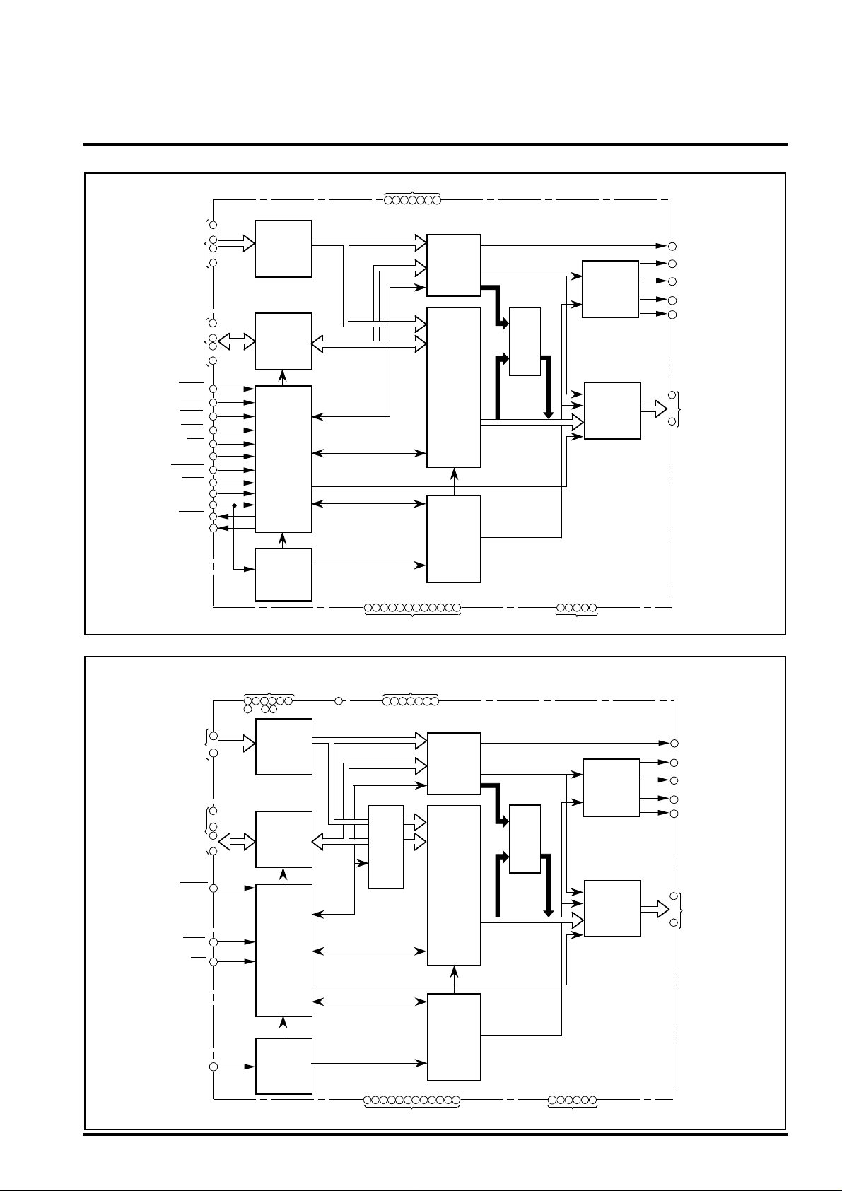
BLOCK DIAGRAM 1
MPU ADD RESS
BUS
MPU DATA BUS
CONTROL REGISTER
CHIPSELECT
VRAM CHIP SELECT
HIGH WR ITE STROBE
LOW WRITE
READ STROBE
8/16MPU SELECT
RESET
BUS HIGH ENABLE
BUS SWAP
MPU CLOCK
WAIT
CYCLE STEAL ENABLE
STROBE
A<14:0>
D<15:0>
IOCS
MCS
HWR
LWR
MPUSEL
RESET
BHE
SWAP
MPUCLK
WAIT
CSE
RD
VDD
8 23 34 425263
15
–
22
26
–
32
43
––
50
53
60
2
6
3
4
5
12
11
14
33
9
7
36
ADDRESS
BUFFER
DATA
BUFFER
MPU I/F
CONTROL
CIRCUIT
CLOCK
CONTROL
(BASIC
TIMING
CONTROL)
1 10 13 2425354041 516465
VSS
77
CONTROL
REGISTER
VRAM
19200byte
BUS
ARBITER
TIMIG
CONTROL
(CYCLE
STEAL
CONTROL)
80
GRAY SCALE
PATTERN
TABLE
373839
N.C
LCD
DISPLAY
TIMING
CONTROL
CIRCUIT
LCD
DISPLAY
DATA
CONTROL
CIRCUIT
78 79
61
LCDENB
DISPLAY DATA
66
CP
TRANSFER CLOCK
DISPLAY DATA LATCH
67
LP
PULSE
FIRST LINE MARKER
68
FLM
SIGNAL
62
LCD ALTERNATING
M
SIGNAL
69
–
VD<7:0>
76
LCD CONTROL
SIGNAL
LCD DISPLAY
DATA BUS
BLOCK DIAGRAM 2
MPU ADDRESS
BUS
MPU DATA BUS
CONTROL REGISTER
CHIP SELECT
LOW WRITE STROBE
READ STROBE
MPU CLOCK
2
A<7:1>
D<15:0>
IOCS
LWR
RD
MPUCLK
(When interfacingwiththeLCD module built-insystem andhaving the maximum number ofpins connectedwithMPU)
INPUT FIXED PIN
3 6 11 12 14
–
26
32
33
16
22
43
–––
50
53
60
2
4
5
9
ADDRESS
BUFFER
DATA
BUFFER
MPU I/F
CONTROL
CIRCUIT
CLOCK
CONTROL
(BASIC
TIMING
CONTROL)
OPEN PIN
15
7
VDD
8 23 34 425263
VRAM
ADDRESS
INDEX
REGISTER
DATA
PORT
REGISTER
77
CONTROL
REGISTER
VRAM
19200byte
BUS
ARBITER
TIMIG
CONTROL
1 10 13 2425354041 516465
VSS
61
LCDENB
66
LCD
DISPLAY
TIMING
CONTROL
CIRCUIT
GRAY SCALE
PATTERN
TABLE
LCD
DISPLAY
DATA
CONTROL
CIRCUIT
78 79
373839
80
36
CP
67
LP
FLM
68
62
M
69
–
VD<7:0>
76
LCD CONTROL
SIGNAL
DISPLAYDATA
TRANSFER CLOCK
DISPLAYDATALATCH
PULSE
FIRSTLINEMARKER
SIGNAL
LCD ALTERNATING
SIGNAL
LCD DISPLAY
DATA BUS
N.C
Page 3

PRELIMINARY
Notice: This is not a final specification.
Some parametric limits are subject to change.
PIN DESCRIPTIONS
Item
MPU
interface
LCD
interface
Others
Pin name
D<15:0>
A<14:0> Input
IOCS
MCS
HWR
LWR
RD
MPUSEL
RESET
MPUCLK
BHE
SWAP
WAIT
CSE
CP
LP
FLM
M
LCDENB
DD Power supply pin
V
SS Ground
N.C No connection
Input/
Output
Input/
Output
Input
Input
Input
Input
Input
Input
Input
Input
Input
Input
Output
Output
Output
Output
Output
Output
Output
Output
MITSUBISHI <DIGITAL ASSP>
M66272FP
LCD CONTROLLER with VRAM
Function
MPU data bus
When selecting 8 bit MPU by MPUSEL input, connect D<15:8> to V
MPU address bus
When selecting 8-bit MPU, use A<14:0>.
When selecting 16-bit MPU, use A<14:1> as a address bus. By combining A<0> and BHE, access to internal
VRAM can be gained.
When driving two screens (dual scan mode), notice that the allowable setup range of VRAM address is
restricted. Use A<7:0> for selecting address of control register.
Chip select input of control register
When this pin is "L", select the internal control register. Assign to I/O space of MPU.
Chip select input of VRAM
When this pin is "L", select the internal VRAM. Assign to memory space of MPU.
High-Write strobe input
When this pin is "L", write data to the internal VRAM. HWR is valid only in using 16-bit MPU
controlled byte access by LWR and HWR.
Low-Write strobe input
When this pin is "L", write data to the internal control register or VRAM.
Read strobe input
When this pin is "L", read data from the internal control register or VRAM.
8/16-bit MPU select input
According to MPU, set "V
SS" for 8-bit MPU and set "VDD" for 16-bit MPU.
Reset input
Use reset signal of MPU. When this pin is "L", initialize (reset) all internal control registers and
counters.
MPU clock
Input system clock output from MPU.
Bus-High-Enable input
This pin is valid when using 16-bit MPU controlling byte access with A<0> and BHE.
Connect to "V
Bus swap input
When selecting 16-bit MPU, connect SWAP to “V
MPU data bus, reversally connect to “V
When selecting 8-bit MPU, connect to “V
8-bit width.
WAIT output for MPU
This signal makes WAIT for MPU. Change WAIT to "L" at timing of falling edge of overlapping with MCS and
RD or LWR and HWR. And return to "H" at synchronization with the rising edge of MPUCLK after internal
processing. (Output WAIT only when requested access from MPU to VRAM is gained during cycle steal
access.)
DD" to select 8-bit MPU.
SS” to transfer VD<n:0> in order of Upper/Lower byte of
DD” in order of Lower/Upper byte.
SS”. Even if connecting to “VDD”, use D<7:0> to access to register of
Cycle Steal Enable output
State output of internal cycle steal access.
Display data bus for LCD
Transfer the LCD display data in synchronization with a rising edge of CP by putting 4-bit or 8-bit in parallel.
The VD<n:0> output pin in use differs depending on the number of driven screens and the display mode.
Display data transfer clock
Shift clock for the transfer of display data to LCD.
Take the display data of VD<n:0> to LCD at falling edge of CP.
Display data latch pulse
This clock use both as the latch pulse of display data for LCD and the transfer of scanning signal.
LP is output when it finishes transferring display data of a line.
Latch of display data and the transfer of scanning signal at falling edge of LP.
First Line Marker signal output
Output the start pulse of scanning line.
This signal is "H" active, the IC for driving scanning line catches FLM at falling edge of LP.
LCD alternating signal output
Signal for driving LCD by alternating current.
LCD (ON/OFF) control signal output
Output data which is set at bit "0" of mode register (R1) in the control register. This signal can be
used for controlling the LCD power supply, because LCDENB is set to "L" by RESET.
DD or VSS.
Number
of pins
16
15
1
1
1
1
1
1
1
1
1
1
1
1
8VD<7:0>
1
1
1
1
1
7
12V
5
3
Page 4

PRELIMINARY
Notice: This is not a final specification.
Some parametric limits are subject to change.
OUTLINE
MITSUBISHI <DIGITAL ASSP>
M66272FP
LCD CONTROLLER with VRAM
M66272FP is a graphic display only controller for displaying a dot
matrix type STN-LCD.
• LCD display mode
It is capable of displaying six types of LCD by combining the
panel configuration, binary/gray scale, LCD display data bus
width.
Display
mode
• Control register
When accessing the control register from MPU, use pins IOCS,
LWR, RD, A<7:0> and D<7:0>. (However, use D<15:0> only
when 16-bit MPU controls the LCD module built-in support
function.)
The IC contains the following registers as control registers.
• VRAM
This IC has a built-in 19200-byte VRAM which is equivalent to
two screens of 320 x 240 dots LCD.
When accessing VRAM from MPU, use pins MCS, HWR, LWR,
RD, BHE, A<14:0> and D<15:0>.
Use of MPUSEL input can support both 8-bit MPU and 16-bit
MPU.
The VRAM address settable range is restricted depending on
the panel configuration, as follows.
VRAM address settable range
♦When single scan mode
♦When dual scan mode
Panel
configuration
1
2
Single
scan
3
4
5
Dual
scan
6
Operation control
SupportingLCD modulebuilt-in type
Gray scale pattern table
• A<14:0>=0000 to 4AFFH --- 19200 byte
0000H
• For the 1st screen --- A<14:0>=0000 to 257FH --- 9600 byte
• For the 2nd screen --- A<14:0>=2580 to 4AFFH --- 9600 byte
0000H
VRAM for the 1st screen
2580H
VRAM
Binary/
gray scale
Binary
Gray scale
Binary
Gray scale
4AFFH
257FH
LCD display
data
4bit
8bit
4bit
8bit
4bit
4bit
R1 to R11
R12 to 14 or R15 to 16
R17 to R80
Displayable LCD
size
Equivalent to
640 x 240
Equivalent to
320 x 240
Equivalent to 320 x
240 x 2 screens
Equivalent to 320 x
240 x 2 screens
• Cycle steal system
Cycle steal system is interact method of transforming display
data for LCD from VRAM and accessing VRAM from MPU on
the basic cycle (MAINCLK) of internal operation.
Basic timing is two clocks of MAINCLK, and assign first clock to
the access from MPU to VRAM and second clock to the transfer
of display data from VRAM to LCD.
In accessing VRAM from MPU, output WAIT. Change WAIT to
"L" at the timing of the falling edge of overlapping with MCS and
RD or LWR / HWR, and return to "H" at synchronizing with rising
edge of MPUCLK after internal processing.
For the cycle steal system, this IC provides a cycle steal control
function to improve data transfer efficiency in a line. This function gains access with the cycle steal system by taking WAIT for
MPU during the display term with necessity for the display data
transfer from built-in VRAM to LCD. On the other side, it does
not output WAIT for keeping throughput of MPU during
horizontal synchronous term (idle running term) with no
necessity for the display data transfer from VRAM to LCD side.
• Output to LCD side
LCD display data VD<7:0> is output in parallel per 4 bits or 8
bits in synchronization with the rising edge of CP.
Pin VD<n:0> differs depending on the display mode.
Single scan
4-bit transfer
VD<3:0> VD<7:0> VD<3:0>
Display mode
When display data for a line has been sent, LP outputs data in
synchronization with the falling edge of MAINCLK.
The IC enables adjustment to an optimum value of the frame
frequency as requested from the LCD PANEL side by adjusting
pulse width of LP with the LPW register value.
FLM is output when the display data for the first line has been
sent.
M output is an LCD alternating signal for driving LCD with
alternating current.
M output cycles can be set in lines with the M output cycle
variable register and is available to prevent LCD from
deterioration.
• Gray scale display function
Gray scale display can assign 2-bit VRAM data to a picture
element of LCD display to show the display density at four
levels.
Gray scale display pattern tables 0 and 1 (4 x 4 matrix x 16
patterns x 2 medium gray scale), consisting of SRAM of 64
bytes in total, can set any gray scale display pattern.
• Application to reflective color type LCD
The above gradation display function is available to control
about four display colors on the reflective color type LCD with
ECB (Electrically Controlled Birefringence).
1 3 2 4 5 6
8-bit transfer 4-bit transfer
Dual scan
VD<7:4>
VRAM for the 2nd screen
4AFFH
4
 Loading...