

MITSUBISHI SEMICONDUCTORS
(SOUND PROCDSSOR ICs)
SERIES
PRELIMINARY
Notice ; This is not a final specification.
M65851FP
SERIES
50
KARAOKE
some parametric limits are subject to change.
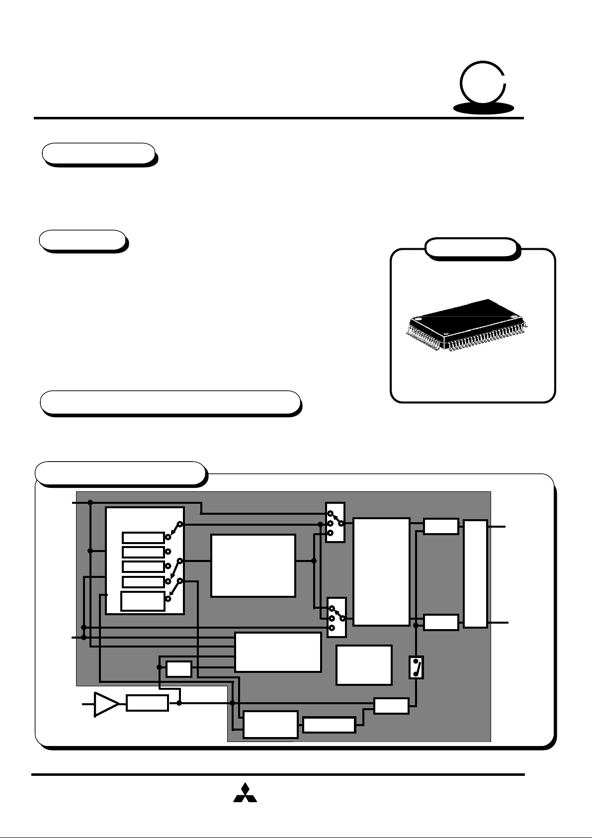
SINGLE CHIP KARAOKE PROCESSOR
DESCRIPTION
*The M65851FP is an LSI that not only contains circuits (echo and key control) necessary for Karaoke but also improves
other peripheral functions.
*This IC has full peripheral functions including vocal cut, phase shifter, equalizer,detection of intervals between songs,
digital surround, and Karaoke scoring. It is therefore suitable not only for dedicated Karaoke units but also for radio
cassette tape recorders, TV,VCR,and miniature unit audio systems with Karaoke function.
FEATURES
*Capable of composing echo and key control circuits necessary for Karaoke system
for Karaoke system with a single chip
*Echo circuit is capable of supporting digital surround by adopting 16Kbit RAM
built-in digital delay
*17steps of -8 to +8 for key control (1step is equivalent to a half tone)
*Karaoke entertainment functions such as Karaoke scoring,vocal cut, equalizer,
phase shifter, detection of intervals between songs, and magic voice functions
*Generation of unnecessary radiation is avoided because clock's built-in
current-control oscillation circuit keeps clock effects inside the clock
*Built-in automatic reset circuit activated with power turned on
*5V single power supply
RECOMMENDED OPERATING CONDITION
Supply voltage range..........................Vcc=4.5~5.5V
Rated supply voltage......................................Vcc=5V
SYSTEM CONFIGURATION
Lch
INPUT
Rch
INPUT
SOURCE
SELECTOR
R
L
R+L
MIC
VOCAL
CUT
ALC
KEY CONTROL
SCORE SYSTEM
MUSIC
SEARCH
PHASE
SHIFTER
(ON/OFF)
Outline 80P6N-A
0.8mm pitch QFP
(20.0mmx14.0mmx2.8mm)
MIX
EQ
MIX
Lch
OUTPUT
Rch
OUTPUT
MIC
MIC
AMP
MIC VOL
ECHO/
SURROUND
MITSUBISHI
ELECTRIC
DELAY VOL
MIX
D-65851-65D
( / 36 )
1
PRELIMINARY
Notice ; This is not a final specification.
some parametric limits are subject to change.
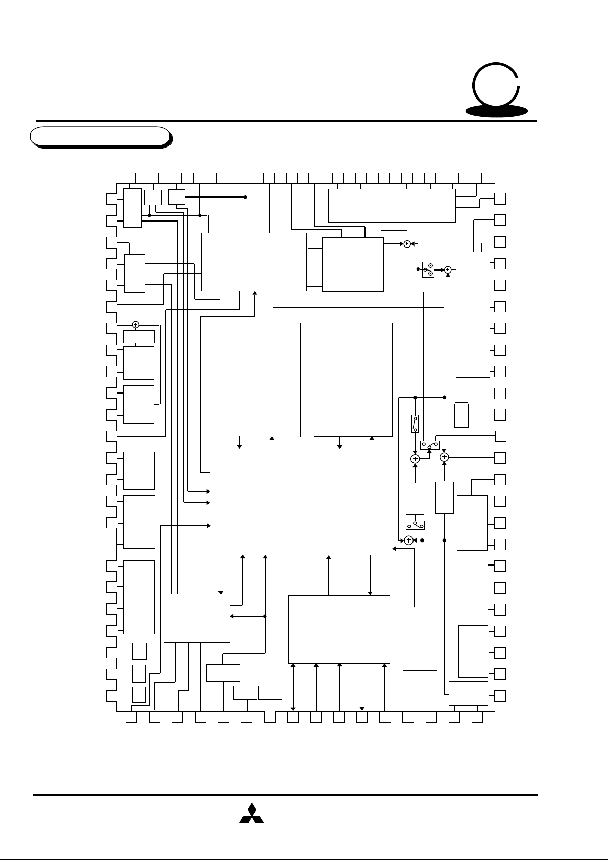
PIN CONFIGURATION
MITSUBISHI SEMICONDUCTORS
(SOUND PROCDSSOR ICs)
M65851FP
50
KARAOKE
SERIES
SERIES
MBPF2
MBPF3
LBPF1
LBPF2
LBPF3
KSIGIN
KCOUT
KOLPF2
KOLPF1
KHPF2
KHPF1
KCISIG
KILPF1
MBPF1
1
2
3
4
5
6
7
8
9
10
11
12
13
MGAIN
BPF1
BPF2
VOL
LPF
HPF
LPF
Gain
LGAIN
Gain
MICIN
76 75 74 73 72
77801779 78
SOURCE SELECTOR
SCORE
KEYCON
VCFIL
L RMIC
LIN
16Kbit
SRAM
RIN
DELAY
PS1
PS2
71
PHASE
SHIFTER
16Kbit
SRAM
EQL1
70 69
EQL2
EQL3
Equalizer
EQL4
68 67
EQLAMPIN1
EQLAMPIN2
66 65
EQLAMPOUT
Equalizer
VCC
GND
64
LOUT
63
ROUT
62
EQRAMPOUT
61
EQRAMPIN2
60
EQRAMPIN1
59
EQR4
EQR3
58
57
EQR2
56
EQR1
55
VCC2
54
AGND2
53
DOUT
52
DISIG
KILPF2
KADCINTIN
KADCINTOUT
KADCCONT
KDACCONT1
KDACCONT2
KDACINTOUT
KDACINTIN
REF
AGND1
AVCC1
14
15
16
18
19
20
21
22
23
24
25 26 27
ADC
DAC
GND
VCCREF
KCSEL
KARAOKE
SCOREING
CLOCK
28
VDD
29 30
MCK
GND
VDD
31
DGND
LOGIC
MCU
INTERFACE
33 34 35 36 37 38 39 40
32
DATA
CLOCK
REQ
STROBE
D.VOL
AUTO
RESET
TEST
TEST1
W/RSEL
F.VOL
TEST2
DOLPF3
LPF
51
50
49
LPF
48
47
46
ADC
45
44
43
DAC
42
41
DOLPF2
DIN
DILPF1
DILPF2
DILPF3
DADCINTIN
DADCINTOUT
DADCCONT
DDACCONT
DDACINTIN
DDACINTOUT
DOLPF1
SCORETEST1
SCORETEST2
SCORETEST3
MITSUBISHI
ELECTRIC
( / 36 )
2
PRELIMINARY
Notice ; This is not a final specification.
some parametric limits are subject to change.
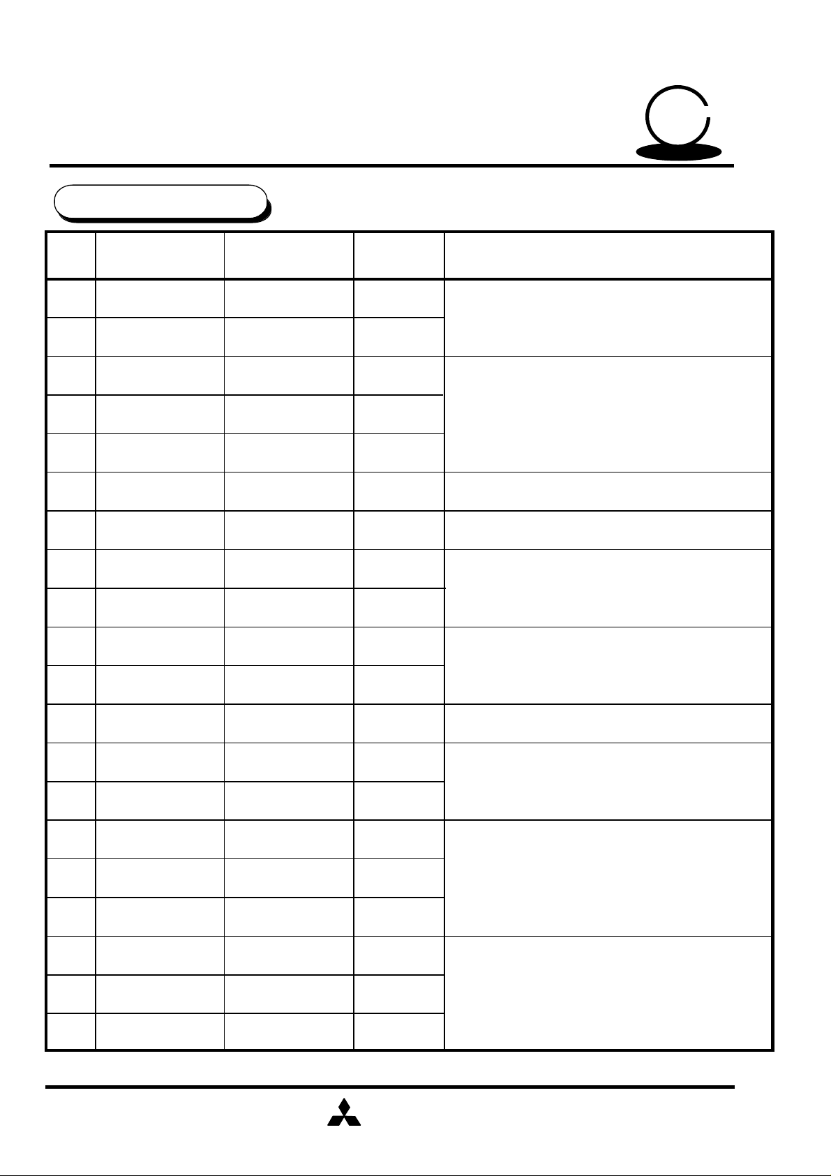
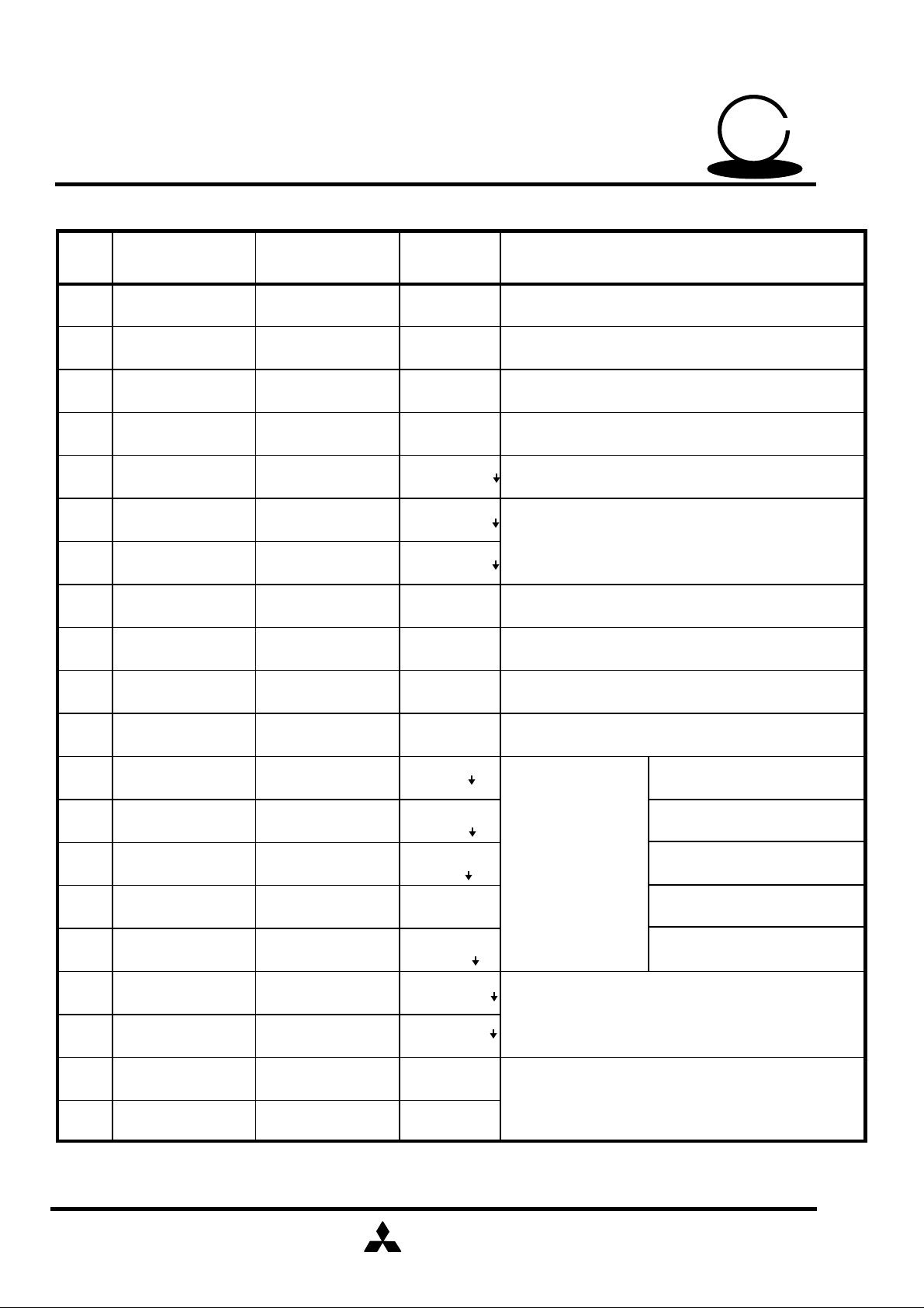
PIN DESCRIPTION
MITSUBISHI SEMICONDUCTORS
(SOUND PROCDSSOR ICs)
M65851FP
50
KARAOKE
SERIES
SERIES
Pin No.
1
2
3
4
5
6
7
8
9
10
11
12
13
14
15
16
Symbol Name I/O Function
MBPF2
MBPF3
LBPF1
LBPF2
LBPF3
KSIGIN
KCOUT
KOLPF2
KOLPF1
KHPF2
KHPF1
KCISIG
KILPF1
KILPF2
KADCINTIN
KADCINTOUT
Microphone band
pass filter2
Microphone band
pass filter3
Line band
pass filter1
Line band
pass filter2
Line band
pass filter3
Key controled
signal input
Key control output
Low-pass filter
2 output
Low-pass filter
1 input
High-pass filter
2 output
High-pass filter
1 input
Key control
signal output
Low-pass filter
1 input
Low-pass filter
2output
A/D integrator
input
A/D integrator
output
I
O
Composes band pass filter for Karaoke scoring
(For microphone signal)
-
I
O
I
O
O
I
O
I
-
I
O
I
O
Composes band pass filter for Karaoke scoring
(For reference signal)
Key controled signal input
Key contorol signal output
Post-filter after D/A conversion for key control
High-pass passage filter for high-pass through
Output by selecting from L,L+R/2,L-R,and
microphone input
Pre-filter after D/A conversion for key control
Composes an A/D conversion integrator with
external C
17
18
19
20
KADCCONT A/D control
KDACCONT1
KDACCONT2
KDACINTOUT
D/A control 1
D/A control 2
D/A integrator
output
-
-
-
O
MITSUBISHI
ELECTRIC
Composes a D/A conversion integrator with
external C
( / 36 )
3
PRELIMINARY
Notice ; This is not a final specification.
some parametric limits are subject to change.
MITSUBISHI SEMICONDUCTORS
(SOUND PROCDSSOR ICs)
M65851FP
50
KARAOKE
SERIES
SERIES
Pin No.
21
22
23
24
25
26
27
28
29
30
Symbol Name I/O Function
KDACINTIN
D/A integrator
input
REF Reference
AGND1
VCC1
KCSEL
SCORETEST1
SCORETEST2
SCORETEST3
Analog GND1
Analog
power supply1
Key control selector
Score test selector1
Score test selector2
Score test selector3
MCK
VDD
Digital Power supply
I
-
-
-
I:CMOS20kΩ Controls the Key selector key control mode or not
I:CMOS20kΩ
I:CMOS20kΩ
O:CMOS Score test selector ; normally no connect
-Clock control
-
Composes a D/A conversion integrator with
external C
Analog reference voltage = 1/2Vcc
5V
Score test selector ; normally set to L level
External R controls built-in clock generator circuit
.
.
31
32
33
34
35
36
37
38
39
40
DGND
DATA
CLOCK
STROBE
REQ
W/RSEL
TEST1
TEST2
DOLPF3
DOLPF2
Digital GND
Serial data
Clock control
Strobe
Request Request output
Write-Read
selector
Test signal
control input1
Test signal
control input2
Low-pass filter 3
output
Low-pass filter 2
input
-
I:CMOSShumitt
50kΩ
O:CMOS
I:CMOSShumitt
50kΩ
I:CMOSShumitt
50kΩ
O:CMOS
I:CMOSShumitt
50kΩ
I:CMOS20kΩ
I:CMOS20kΩ
O
I
Serial data input/output
Shift clock output
Micro computer
interface
Strobe output
Control the selector write/read
Test input pin ; normally set to L
Post-filter after D/A conversion for
digital delay
MITSUBISHI
ELECTRIC
( / 36 )
4
PRELIMINARY
Notice ; This is not a final specification.
some parametric limits are subject to change.
MITSUBISHI SEMICONDUCTORS
(SOUND PROCDSSOR ICs)
M65851FP
50
KARAOKE
SERIES
SERIES
Pin No.
41
42
43
44
45
46
47
48
49
50
51
52
Symbol Name I/O Function
DOLPF1
DDACINTOUT
DDACINTIN
DDACCONT
DADCCONT
DADCINTOUT
DADCINTIN
DILPF3
DILPF2
DILPF1 -
DIN
DISIG
Low-pass filter 1
input
D/A integrator
output
D/A integrator
input
D/A control
A/D control
A/D integrator
output
A/D integrator
input
Low-pass filter 3
output
Low-pass filter 2
input
Low-pass filter 1
input
Delay select signal
input
Delay select signal
output
-
O
I
-
-
O
I
O
I
I
O
Post-filter after D/A conversion for
digital delay
Composes a D/A conversion integrator with
external
Composes a A/D conversion integrator with
external
Pre-filter before A/D conversion for
digital delay
Outputs after selection of echo/surround input signal
53
54
55
56
57
58
59
60
DOUT
AGND2
VCC2
EQR1
EQR2
EQR3
EQR4
EQRAMPIN1
Delay signal output
Analog GND2
Analog
Power supply2
Rch equalizer
adjustment C1
Rch equalizer
adjustment C2
Rch equalizer
adjustment C3
Rch equalizer
adjustment C4
Rch equalizer
input 1
O Delay signal output
-
-
-
-
-
Composes external C for the adjustment of Rch
equalizer characteristics (bass and treble)
-
I
MITSUBISHI
ELECTRIC
( / 36 )
5
PRELIMINARY
Notice ; This is not a final specification.
some parametric limits are subject to change.
MITSUBISHI SEMICONDUCTORS
(SOUND PROCDSSOR ICs)
M65851FP
50
KARAOKE
SERIES
SERIES
Pin No.
61
62
63
64
65
66
67
68
69
70
71
Symbol Name I/O Function
EQRAMPIN2
EQRAMPOUT
ROUT
LOUT
EQLAMPOUT
EQLAMPIN2
EQLAMPIN1
EQL4
EQL3
EQL2
EQL1
Rch equalizer
input 2
Rch equalizer
output
Rch output
Lch output
Lch equalizer
output
Lch equalizer
input 2
Lch equalizer
input 1
Lch equalizer
adjustment C4
Lch equalizer
adjustment C3
Lch equalizer
adjustment C2
Lch equalizer
adjustment C1
I
O
O Rch mixing output
O
O
I
I
-
Composes external C for the adjustment of Rch
equalizer characteristics (bass and treble)
Lch mixing output
Composes external C for the adjustment of Lch
equalizer characteristics (bass and treble)
-
-
-
72
73
74
75
76
77
78
79
80
PS2
PS1
RIN
LIN
VCFIL
MICIN
LGAIN
MGAIN
MBPF1
Phase shift input 2
Phase shift input 1
Rch line input
Lch line input
Vocal cut filter
Microphone input
Line input
gain control
Microphone input
gain control
Microphone band
pass filter2
I
I
I
I
I
I
I
I
-
MITSUBISHI
ELECTRIC
Determines a constant at time of phase shift
Rch line input
Lch line input
Processes frequencies lower than the vocal band
Microphone input
Set gain for the no music detection
Set gain for the microphone detection
Composes band pass filter for Karaoke scoring
(For microphone signal)
( / 36 )
6
MITSUBISHI SEMICONDUCTORS
(SOUND PROCDSSOR ICs)
PRELIMINARY
Notice ; This is not a final specification.
some parametric limits are subject to change.
M65851FP
ABSOLUTE MAXIMUM RATINGS
Symbol Name Test conditions Ratings Units
50
KARAOKE
SERIES
SERIES
Vcc
Vi
Pd
Supply voltage
Circuit current
Input Voltage
Operating
Topr
Tstg
temperature
Storage
temperature
RECOMMENDED OPERATING CONDITION
Symbol Parameter Test conditions
VCC
Analog
supply voltage
6.0
-0.3~Vcc+0.3
815
-20~+75
-40~+125
Limits
Min Typ Max
4.5 5 5.5
V
V
W
°C
°C
Units
V
VDD V4.5 5
VCC-VDD
VIL
VIH
Digital
supply voltage
Analog-Digital
voltage margin
L input level
H input level
-0.3 0 0.3
25 26 27 28
37 38
32 33 34 36 0
25 26 27 28
37 38
32 33 34 36
pin
pin
pin
pin
MITSUBISHI
ELECTRIC
0.7VDD
VDD-1
0
5.5
V
-
-
-
-
0.3VDD
0.8
VDD
VDD V
V
V
V
( / 36 )
7
MITSUBISHI SEMICONDUCTORS
(SOUND PROCDSSOR ICs)
PRELIMINARY
Notice ; This is not a final specification.
some parametric limits are subject to change.
ELECTRICAL CHARACTERISTICS
(Vcc=5V,f=1kHz,vi=100mVrms,F0,Ta=25°C Unless otherwise noted)
Symbol Parameter Test conditions
M65851FP
Limits
Min Typ Max
50
KARAOKE
SERIES
SERIES
Unit
Icc
Circuit current
No signal provided
fck Clock frequency 8 MHz
RID
TOTAL
IOH
IOL
Gv
THD
Pulldown
resistance
"H"Output current
"L"Output current
Gain between
input and output
Output distortion
25 26 27 28
37 38
32 33 34 36
32 35
32 35
pin VOL=1.0V 20 34 -
VOL=0dB
Vo=100mVrms,30kHz L.P.F
pin
pin
pin VOH=4.0V - -20 -10
25 60 90
6.8 9.2
10 20 40 kΩ
25 50 100 kΩ
- 3
-
0
1.3
+ 3
3
Output noise
No
KEY CONTROL
Vomax
VOLATTmax
voltage
Maximum
output voltage
Maximum volume
attenuation
JIS-A
THD=10%
Gain=-∞
-
0.7
-
- 80
1.0
-60
- 65
-
-40
mA
mA
mA
dB
%
dBV
Vrms
dB
Td Delay time
Digital Delay
Sets 10msec with microcomputer
Sets 15msec with microcomputer
Sets 20msec with microcomputer
Sets 30msec with microcomputer
Sets 50msec with microcomputer
Sets 100msec with microcomputer
Sets 130msec with microcomputer
Sets 150msec with microcomputer
Sets 200msec with microcomputer
MITSUBISHI
ELECTRIC
4.2
8.4
13.5
19.7
40.2
86.3
116
128
177
10.2
15.4
20.5
28.7
49.2
98.3
131
148
197
16.2
22.4
27.5
37.7
msec
58.2
110.3
146
168
217
( / 36 )
8
MITSUBISHI SEMICONDUCTORS
(SOUND PROCDSSOR ICs)
PRELIMINARY
Notice ; This is not a final specification.
some parametric limits are subject to change.
(Vcc=5V,f=1kHz,vi=100mVrms,F0,Ta=25°C Unless otherwise noted)
M65851FP
Symbol Parameter Test conditions
50
KARAOKE
Limits
Min Typ Max
SERIES
SERIES
Unit
Gv
THD
Vomax
DIGITAL DELAY
No
Gain between
input and output
Output distortion
Maximum
output voltage
Output
noise voltage
VOL=0dB
Td=10,15,20msec, 30kHz LPF
Td=30msec, 30kHz LPF
Td=50msec, 30kHz LPF
Td=100msec, 30kHz LPF
Td=150msec, 30kHz LPF
Td=200msec, 30kHz LPF
30kHz LPF, THD=10%
Td=10,15,20,30,50msec,
Vi=0mVrms
JIS-A
Td=100msec, Vi=0mVrms
JIS-A
Td=130msec,150msec
Vi=0mVrms ,JIS-A
Td=200msec, Vi=0mVrms
JIS-A
-3 0 +3
0.3
0.5
0.7
1.0
1.5
2.0
-92
-87
-85
-82
0.6
1.0
1.4
2.0
3.0
4.0
-80
-72
-70
-67
dB
%
Vrms0.7 1.0
dBV
Delay volume Gain=-∞
VOLATTmax
Maximum volume
attenuation
Feed back volume Gain=-∞
Gv
THD %
LINE
Vomax
input and output
Output distortion
Maximum
output voltage
Gain between
No
Output
noise voltage
30kHz LPF,upon key control
through
30kHz LPF,upon key control
through
30kHz LPF,THD=10%
upon key control through
JIS-A,upon key control
through
MITSUBISHI
ELECTRIC
-60
-40
-60
0.05
1.8
-95 -88
( / 36 )
9
-40
0.1
dB
dB
dB- 3 0 + 3
Vrms1.2
dBV
MITSUBISHI SEMICONDUCTORS
(SOUND PROCDSSOR ICs)
PRELIMINARY
Notice ; This is not a final specification.
some parametric limits are subject to change.
(Vcc=5V,f=1kHz,vi=100mVrms,F0,Ta=25°C Unless otherwise noted)
M65851FP
Symbol Parameter Test conditions
50
KARAOKE
Limits
Min Typ Max
SERIES
SERIES
Unit
CS
Zi
LINE
separation
Input impedance kΩ10 20
Vocal
Channel
Grej
GBBmax
GBCmax
GTBmax
GTCmax
EQ;BASS,TREBLE
removal ratio
Maximum bass
boost volume
Maximum bass
cut volume
Maximum treble
boost volume
Maximum treble
cut volume
upon key control through
Lin=400Hz, Rout JIS-A
f=100Hz
f=100Hz
f=10kHz
f=10kHz
40
18
9 12 15
-15 -12
-9
9 12 15
-15 -12 -9
dB-70 -50
dB14Vocal cut
dB
MITSUBISHI
ELECTRIC
( / 36 )
10
MITSUBISHI SEMICONDUCTORS
(SOUND PROCDSSOR ICs)
PRELIMINARY
Notice ; This is not a final specification.
some parametric limits are subject to change.
M65851FP
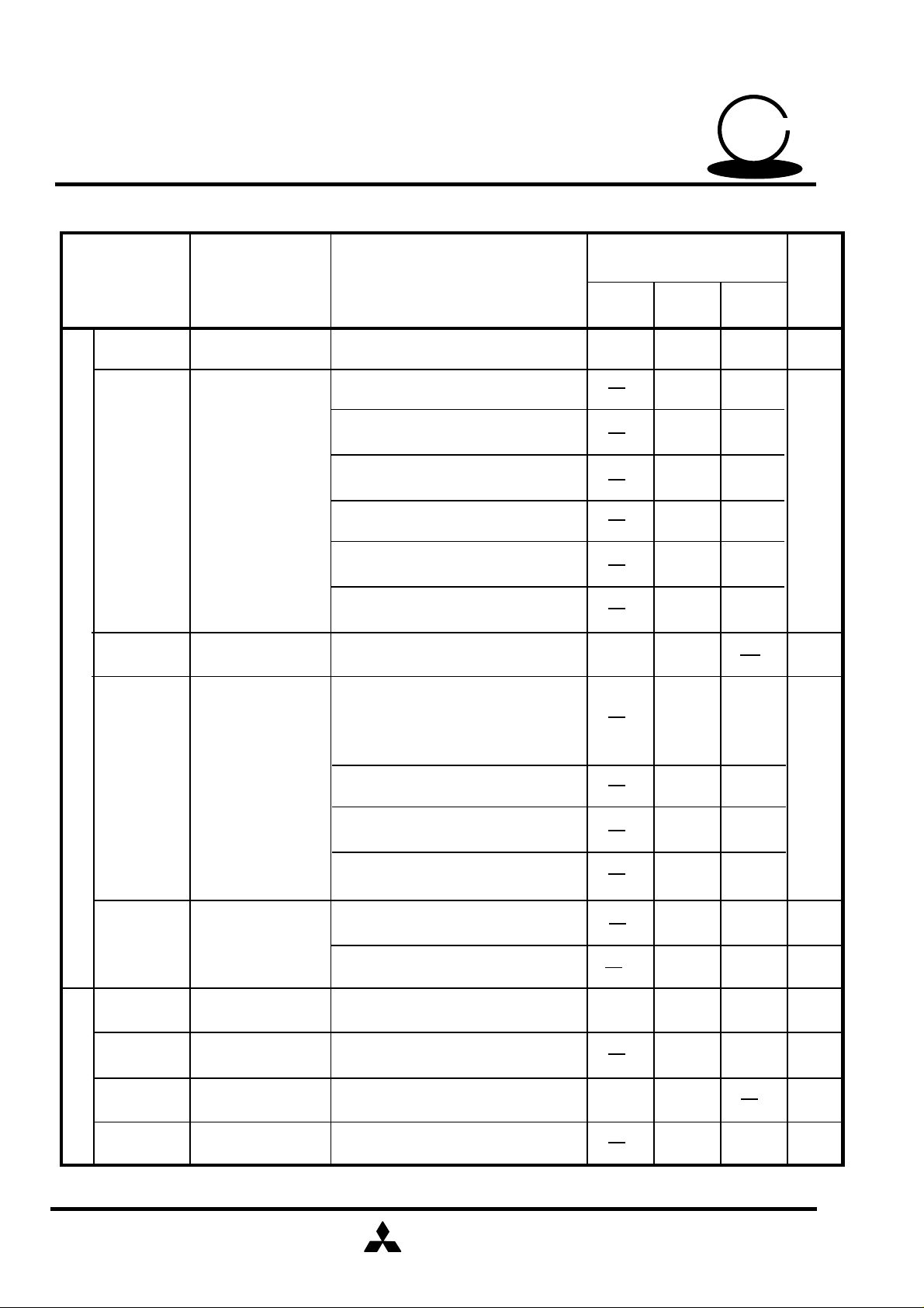
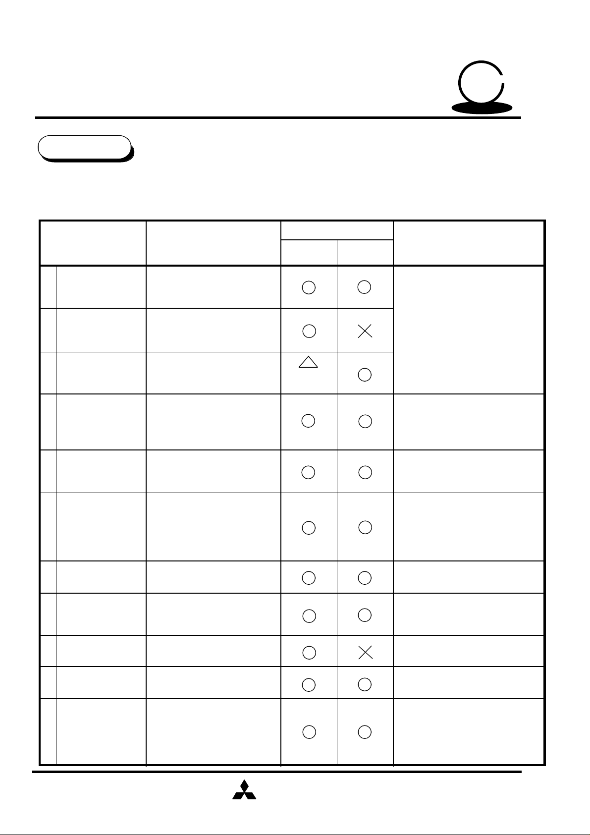
FEATURES
M65851FP provides the following functions and can configurate all Karaoke
functions with only a single chip.
Usable or not
Function Explanation Notes
Built in 16KSRAM
1 Digital echo
Digital key control
2
Digital
3
Surround
Delay time (changeable)
100ms,130ms150ms,200ms
Built in 16KSRAM
-8 ~ +8
17 steps
Built in 16KSRAM
Digital Surround
10ms ~ 50ms 5 kinds
Key set
mode
Switch with
the Echo
not key
set mode
At Key set mode
Capable of use echo or surround
Not key set mode
Capable of use both echo and
surround
50
KARAOKE
SERIES
SERIES
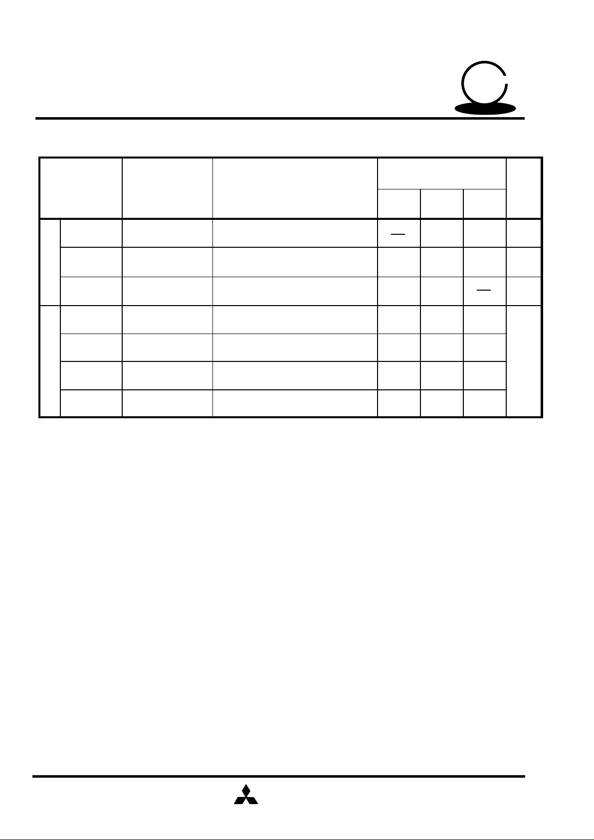
Phase shifter
4
surround
Equalizer
5
Source selector
6
7
Scoring function
8
Help vocal
function
Voice key control
9
Changeable the effect
thanks to the external R
Bass/Treble
-12dB ~ +12dB/2dB
13 steps changeable
Provided all multiple voice
soft, L,R,(L+R)/2,
VOCAL CUT
L-R(for Digital Surround)
Key control bypass
Scoring the Mic vocal input
At the mic vocal is nothing ,
reference vocal is mixed
output.
Input the mic voice to key
control (change voice tone)
10 Music search Detect to line input level
Capable of use both key
control and echo
Bass; Resonance type
Treble ; Filter type
Compare the reference vocal and
mic vocal frequency
At Key set mode
capable to use voice key control or
key control
At music input is nothing ,key
control level is reset automatically
11
Others
MCU Inter face
Current control type
oscillation circuit
Automatic mute
Automatic reset
MITSUBISHI
ELECTRIC
( / 36 )
11

MITSUBISHI SEMICONDUCTORS
(SOUND PROCDSSOR ICs)
PRELIMINARY
Notice ; This is not a final specification.
some parametric limits are subject to change.
M65851FP
50
KARAOKE
Delay Block
Delay Block provides a delay signal which using digital echo or digital surround.
1.Constitution
4700p
1000p
0.068µ
0.1µ 0.1µ
0.068µ
4700p
1000p
SERIES
SERIES
INPUT
2.Function
1 Delay time
Capable to set the follow delay time;
52
+
50 49 48 47 46 45 44 43 42 41 40 3951
LPF
FEEDBACK
VOLUME
ADC
DELAY
16Kbit RAM
DAC LPF
DLSW3
+
DLSW1
1
DLSW2
2
DELAY
VOLUME
+
OUTPUT
Surround
2 Switch mode
Mode DLSW1
Echo
Surround
Mode
Echo
Delay time
100,130,150,200msec
10,15,20,30,50msec
DLSW2
Echo"1"
1
2
ON
OFF
OFF
MITSUBISHI
ELECTRIC
1
2
1
Set the echo volume using the delay
volume(Change the delay signal gain)
Echo"2"
Set the microphone volume using the
delay volume
(Change the delay signal+input signal gain)
( / 36 )
12

PRELIMINARY
Notice ; This is not a final specification.
some parametric limits are subject to change.
MITSUBISHI SEMICONDUCTORS
(SOUND PROCDSSOR ICs)
M65851FP
50
KARAOKE
SERIES
SERIES
Delay signal Mute
MUTE OFF
MUTE ON
3 Input/ output LPF
Input/output LPF is formed following block.
4700pF
50
(41)
1
INPUT
Input/ output LPF
DLSW3
ON
OFF
1000pF
49
(40) (39)
48
OUTPUT
4 Volume
Volume
Delay volume
Feedback volume
2
Mode
Echo
Surround
Switch
conditions
1
2
Cut off
frequency
3.0kHz
7.0kHz
Mode
+6dB ~ -12dB / 3dB step and -∞ 8 level
-2dB ~ -6dB / 1dB step and -8dB,-10dB,-∞ 8 level
MITSUBISHI
ELECTRIC
( / 36 )
13

MITSUBISHI SEMICONDUCTORS
(SOUND PROCDSSOR ICs)
PRELIMINARY
Notice ; This is not a final specification.
some parametric limits are subject to change.
M65851FP
Key Control Block
It can be changed the key of KARAOKE accompaniment.
And it can change a microphone voice which like a monkey voice.
it also can use digital echo block at not key set mode.
1.Key control condition ,key control set mode or not
50
KARAOKE
SERIES
SERIES
25
2.Constitution
INPUT
2.2µ
25 612
KCSEL
L
H
3300p
10k
4.7k
820p
13 14 15 16 17 18 20 21 9 8
LPF
0.047µ 0.068µ
ADC
Key control condition
Key control set mode
Not key control set mode
0.068µ
0.068µ
19
DAC
0.047µ
3.9k
4700p
15k15k10k
1000p
560p
5.6k
1000p
2.7k
11 10
LPF HPF
1000p
OUTPU
T
2.2µ
7
3.Function
1 Key change level
Key change
level
(1step is half tone)
KEY CONTROL
VOL
+
16Kbit RAM
KEY UP
KEY DOWN
+8 +7 +6 +5 +4 +3 +2 +1 0 -1 -2 -3 -4 -5 -6 -7 -8
MITSUBISHI
ELECTRIC
( / 36 )
14

MITSUBISHI SEMICONDUCTORS
(SOUND PROCDSSOR ICs)
SERIES
PRELIMINARY
Notice ; This is not a final specification.
some parametric limits are subject to change.
M65851FP
SERIES
50
KARAOKE
2 Volume
It set the key control signal gain.
+4dB~-6dB/2dB step and -10dB, -∞ 8 level
3 Key control level automatic reset
When music search detects no signal ,key control level is automatic changed normal (0)
level.
(Provides ON/OFF switch with MCU interface)
4.Echo Block (using key control block)
At not key control set mode,digital echo is able to use ,when the following block using.
INPUT
25
1.0µ Echo Feed
4700p
24k
2.2µ
24k
1000p
12 6
13 14 15 16 17
LPF
0.068µ
ADC
0.1µ
DELAY
back volume
0.1µ
18 20 21 9 8
0.068µ
19
24k
DAC
4700p
24k24k24k
1000p
LPF
VOL
24k
11 10
BUF
24k
+
OUTPUT
2.2µ
7
16Kbit RAM
Delay time 100msec,130msec,150msec,200msec
Volume level +4~-6dB/2dB step and -10dB, -∞ 8 level
(same as key control volume)
MITSUBISHI
ELECTRIC
( / 36 )
15

MITSUBISHI SEMICONDUCTORS
(SOUND PROCDSSOR ICs)
PRELIMINARY
Notice ; This is not a final specification.
some parametric limits are subject to change.
M65851FP
Phase Shifter Block
Following is the phase shifter block, which makes phase surround effect.
20k
Lch INPUT
Phase Shifter
20k
20k 20k
Surround SW
R(internal)
SERIES
SERIES
50
KARAOKE
Lch OUTPUT
Key control
block output
Rch INPUT
Switch conditions
Surround
SW ON
20k
20k
R=13kΩ
R=16kΩ
R=20kΩ
73
C(external)=0.022µF
72
20k
Surround effect
Max
Typ
Min
20k
Rch OUTPUT
Surround SW OFF
MITSUBISHI
ELECTRIC
Nothing
( / 36 )
16

MITSUBISHI SEMICONDUCTORS
(SOUND PROCDSSOR ICs)
PRELIMINARY
Notice ; This is not a final specification.
some parametric limits are subject to change.
M65851FP
Equalizer Block
Following is the equalizer block, which can control the both gain bass and treble.
Bass resonance block
Equalizer Block
R2
50
KARAOKE
SERIES
SERIES
136k
71 70
(56)
1.8k
(57)
69
(58)
68
(59)
65
(62)
64
(63)
EQOUT
C3
R1
C1 C2
0.033µ
0.022µ 0.47µ
Bass block is resonance type which is used simulated inductor amplifier.Treble block is
filter type. These can be set -12dB ~ +12dB/2dB step.
Following is a center frequency "fo" ,"Q" (bass resonance block).
fo = 1/(2π C1•C2•R1•R2) (Hz)
Q = (C1•R2) / (C2•R1)
MITSUBISHI
ELECTRIC
( / 36 )
17

MITSUBISHI SEMICONDUCTORS
(SOUND PROCDSSOR ICs)
PRELIMINARY
Notice ; This is not a final specification.
some parametric limits are subject to change.
M65851FP
50
KARAOKE
Vocal Cut Block
The sound components of the same phase and same sound volume in the L and R
channels are attenuated.
This made also allows components with lower frequency than the vocal band to pass
through the filter, to compensate insufficient low-frequency sound.
vocal cut block
SERIES
SERIES
20k 20k
Lch INPUT
R
20k
Rch INPUT
1
fvc=
2πCR
LPF is formed by the internal R (20kΩ) and the external C, when
Where C=0.15µ F , cut off frequency is 53Hz .
vocal cut block
76
C
0.15É
20k
20k
20k
76
C
0.15µ
Vocal cut
OUTPUT
20k
MITSUBISHI
ELECTRIC
( / 36 )
18

PRELIMINARY
Notice ; This is not a final specification.
some parametric limits are subject to change.
Scoring Function
Scoring function judge the mic vocal input .
1.Scoring output form
Mic input is judged from 0 to 99 level.
2.Constitution
MITSUBISHI SEMICONDUCTORS
(SOUND PROCDSSOR ICs)
M65851FP
50
KARAOKE
SERIES
SERIES
Scoring function is constituted following two ways.
Judgment conditions Function Ratio
1 Compare
the frequency
2 Vocal level
judgment
Compare the frequency reference voice and
microphone voice
Vocal level judgment
(as vocal is bigger than reference level,judgment is good)
75%
25%
MITSUBISHI
ELECTRIC
( / 36 )
19

MITSUBISHI SEMICONDUCTORS
(SOUND PROCDSSOR ICs)
SERIES
PRELIMINARY
Notice ; This is not a final specification.
some parametric limits are subject to change.
M65851FP
SERIES
50
KARAOKE
3.Music search
Music search is constituted following .
1 Input signal reference level comparison
2 Music detection
3 No music detection
1 Input signal reference level comparison
Input signal reference level comparison is comstituted amplifier and level comarison.
When input signal is bigger than reference level,level comparison output the pulse
which added internal clock.
Input signal
Clock signal
pulse output
(after level detection)
Then reference level can be changed ,thanks to the following internal R2 and
external R1 which determine the amplifier gain .
Lch
Level comparator
reference
level
Internal resistance
precision is about
±30%.
78
R1
MITSUBISHI
ELECTRIC
R2=50kΩ
Gain Gv = (R1 + R2) / R1
20
( / 36 )

MITSUBISHI SEMICONDUCTORS
(SOUND PROCDSSOR ICs)
SERIES
PRELIMINARY
Notice ; This is not a final specification.
some parametric limits are subject to change.
M65851FP
SERIES
50
KARAOKE
2 Music detection
To search a music interval, it is necessary to judge if it is a music or not. This judgment
is made by monitoring the 20 seconds and counting the pulse signal (after level detection).
The pulse signal counts is bigger than fixed counts, it is judged as a music.
Pulse counter is reset whenever monitor 20 seconds or judged no music decision.
about 20 sec
pulse output
(after level detection)
Music decision
3 No music detection
After Music decision ( 2 ), no music is judged when no pulse in level detection at 3
seconds.But if there isn't no pulse when monitoring the3 seconds, no music decision
counter is reset .
about 3 sec
pulse output
(after level detection)
No music decision
MITSUBISHI
ELECTRIC
( / 36 )
21

MITSUBISHI SEMICONDUCTORS
(SOUND PROCDSSOR ICs)
SERIES
PRELIMINARY
Notice ; This is not a final specification.
some parametric limits are subject to change.
M65851FP
SERIES
50
KARAOKE
4.Signal input circuit
Signal input circuit is constituted the following band pass filter, which cuts the input signal to
vocal band width.
C1=0.15µF
80 1 2
(3)
(4)
C2=1500pF
(5)
R2=100kΩ
INPUT
R1=10kΩ
Low level cut off frequency fcl and High level cut off frequency fch is
fcl= 1/2πC1R1 = 106 Hz fch = 1/2πC2R2 = 1.1kHz
and , the gain of amplifier Gv is
Gv = R2/R1 = 20 dB.
Same as the band pass filter is constituted microphone signal input.
OUTPUT
Automatic Vocal Support
In case using the Karaoke system , when microphone input level is nothing ,
then audio source vocal appears and help the microphone songs.
(It can set only following conditions , audio source selector sets Lch monaural or
vocal cut)
Microphone input level Source selector mode
On
Off
Lch monaural vocal cut
(L+R)/2
(L+R)/2
Changing time from microphone input level changed to source selector
changed is following .
Attack time (Off On)0 sec
Release time (On Off) 1sec or 2 sec
others
same as
microphone
input
MITSUBISHI
ELECTRIC
22
( / 36 )

MITSUBISHI SEMICONDUCTORS
(SOUND PROCDSSOR ICs)
PRELIMINARY
Notice ; This is not a final specification.
some parametric limits are subject to change.
The timing of microphone input signal detection
M65851FP
50
KARAOKE
SERIES
SERIES
Microphone
input
level output
microphone
signal
detection
On
release time
OFF
attack time 0s
On
reference level
Following is the microphone input signal judgment block , which includes amplifier so
reference level can regulate.
MIC
Level Comparator
Internal resistance
precision is about
±30%.
79
R1
Gain Gv = (R1 + R2)/R1
MITSUBISHI
ELECTRIC
R2=50kΩ
( / 36 )
23

MITSUBISHI SEMICONDUCTORS
(SOUND PROCDSSOR ICs)
SERIES
PRELIMINARY
Notice ; This is not a final specification.
some parametric limits are subject to change.
M65851FP
SERIES
50
KARAOKE
Oscillation Circuit
This IC incorporates a current control type clock oscillator circuit in it, thus providing
circuit configuration just by connecting a R for current control pin 29 (CLKCNT).
Fully internal clock supply prevents occurrence of undesired radiation without affecting
any external circuit.
The oscillator frequency fck is following.
fck = 8 MHz
Reset
This IC is automatically reset when the power is turned on , and is automatically canceled
nearly 120msec later.
Function
Echo
Key control
Phase shifter
Equalizer
Source selector
Scoring function
Delay time
Stereo(Key control by pass)
First set
150msec
No changing
OFF
OFF
OFF
MITSUBISHI
ELECTRIC
( / 36 )
24

PRELIMINARY
Notice ; This is not a final specification.
some parametric limits are subject to change.
MCU Interface
MITSUBISHI SEMICONDUCTORS
(SOUND PROCDSSOR ICs)
M65851FP
50
KARAOKE
SERIES
SERIES
1.Constitutions
MCU interface is constituted serial bass interface ,
so the selection, data input or output , is changed
by 36 pin input level .
W/RSEL
L
H
MCU IC(Data input)
IC MCU (Data output)
Conditions36
2.Data input
(1)Data input format
D0
DATA
D1 D2 D3 D4 D5
D7 D8 D9 D10 D11 D12 D13 D14 D15
D6
MCU
Interface circuit
32 33 34 35
DATA CLOCK
STROBE
MCU
REQ
36
W/RSEL
CLOCK
STROBE
(2)Mode creations
D0~D1 select the following each block, and D2 ~ D13 create the particular setting.
D14,D15 are chip address, so this IC can use only when D14="L"and D15="H".
D0 D1
L L
D2~D13
Echo/Surround mode
D14 D15
Chip
addles
L H
Key control mode
L H
H L
H
H
Equalizer/Phase sifter mode
Line mixing/Others mode
MITSUBISHI
ELECTRIC
( / 36 )
25

MITSUBISHI SEMICONDUCTORS
(SOUND PROCDSSOR ICs)
SERIES
PRELIMINARY
Notice ; This is not a final specification.
some parametric limits are subject to change.
1 Echo /Surround mode
D0 D1 D2 D3 D4 D5 D6 D7 D8 D9 D10 D11 D12 D13 D14 D15
M65851FP
SERIES
50
KARAOKE
L L
Echo/Surround
Switch
Echo
delay time
Surround
delay time
Echo/
Surround
Parameter
Echo
delay time
D2 D3 D4 D5LD6 D7
H --
--
-
-
-
-
-
-
--
-
-
-
-
Surround
delay time
-
-
L
L
H
L ---
H
HLH
--
--
-
-
- - -
- - -
-
H L L
L H L
H H L
delay
volume
- -- -
- -- -
-
-
-
-
Feed back
volume
Echo
Surround
L H
Function
On not key control
set mode sets H level
100msec
130msec
150msec
200msec
10msec
15msec
20msec
-
-
-
- - -
-
L L H
H L H
MITSUBISHI
ELECTRIC
30msec
50msec
( / 36 )
26

PRELIMINARY
Notice ; This is not a final specification.
some parametric limits are subject to change.
MITSUBISHI SEMICONDUCTORS
(SOUND PROCDSSOR ICs)
M65851FP
50
KARAOKE
SERIES
SERIES
Parameter
Delay
volume
Feed back
volume
D8 D9 D10 D11 D12 D13
H H H
H H L
H L H
H L L
L H H
L H L
L L H
L L L
- - -
- - -
-
- --
- --
- - -
- - -
- --
- --
-
- --
- --
-
H H H
H H L
H L H
H L L
--
--
Function
+6dB
+3dB
0dB
-3dB
-6dB
-9dB
-12dB
-∞
-2dB
-3dB
-4dB
-5dB
-
- --
- --
- --
2 Key control mode
D0 D1 D2 D3 D4 D5 D6 D7 D8 D9 D10 D11 D12 D13 D14 D15
L H Key change level
Auto
Reset
VSC/
VMC
--
L H H
L H L
L L H
L L L
Key control
volume
-6dB
-8dB
-10dB
-∞
Delay
volume
select
Delay
signal
mute
L
H
MITSUBISHI
ELECTRIC
( / 36 )
27

PRELIMINARY
Notice ; This is not a final specification.
some parametric limits are subject to change.
D2
Parameter
D3 D4 D5
MITSUBISHI SEMICONDUCTORS
(SOUND PROCDSSOR ICs)
M65851FP
D6 D7
D8
Function
50
KARAOKE
SERIES
SERIES
Automatic
key control reset
Key control mode
selector
Key change
level
L
H
-
-
-
-
-
-
-
-
-
-
-
-
- - -
-
- - -
L
- - -
H
- - -
H H L
H L H
H L H
H L H
-
-
H L H
H L L
H L L
H L L
-
L L L
-
- -
- -
- -
- -
L L
H H
H L
L H
L L
H H
H L
L H
L L
automatic reset OFF
automatic reset ON
VMC mode
VSC mode
+8
+7
+6
+5
+4
+3
+2
+1
0
-
-
-
-
-
-
-
-
-
L L L
-
L L L
L L L
L L H
-
-
L L H
L L H
L L H
L H L L L
-
MITSUBISHI
ELECTRIC
L H
H L
H H
L L
L H
H L
H H
-1
-2
-3
-4
-5
-6
-7
-8
( / 36 )
28

PRELIMINARY
Notice ; This is not a final specification.
some parametric limits are subject to change.
MITSUBISHI SEMICONDUCTORS
(SOUND PROCDSSOR ICs)
M65851FP
50
KARAOKE
SERIES
SERIES
Parameter Function
D9 D10
D11
H H H
H H L
Key control
volume set
(when not key
control mode, it
use a echo
volume)
H L H
H L L
L H H
L H L
L L H
L L L
Parameter Function
Delay volume
selector
D12 D13
L
H
-
-
Using an echo volume
Using a microphone volume
+4dB
+2dB
0dB
-2dB
-4dB
-6dB
-10dB
-∞
Delay signal
mute
-
-
3 Equalizer/Phase shifter mode
D0 D1 D2 D3 D4 D5 D6 D7 D8 D9 D10 D11 D12 D13 D14 D15
H L
automatic
vocal support
Phase
shifter
L
H
Equalizer
treble
Mute OFF
Mute ON
Equalizer
bass
L
H
MITSUBISHI
ELECTRIC
29
( / 36 )

PRELIMINARY
Notice ; This is not a final specification.
some parametric limits are subject to change.
MITSUBISHI SEMICONDUCTORS
(SOUND PROCDSSOR ICs)
M65851FP
50
KARAOKE
SERIES
SERIES
Parameter Function
Automatic vocal
support
(It can use only
echo mode)
Phase shifter
surround mode
Equalizer treble mode
D6 D7 D8
D9
D2
D3 D4
L
-
-
H
-
L
-
H
- -
- -
- -
- -
Volume(dB)
D5
-
--
- -
- -
L
L
H
L
H
L
H H
-
Release time 1sec
Release time 2sec
Surround effect Minimum
Surround effect Typical
Surround effect Maximum
D10 D11 D12
OFF
ON
OFF
Equalizer bass mode
D13
Volume(dB)
H H H
H H L
H H L
H L H
H L H
H L L +2
L L L 0
L L L -2
L L H -4
L L H -6
L H L -8
L H L -10
L
H
L
H
L
H
L
H
L
H
L
HL H L H
+12
+10
+8
+6
+4
H H H
H H L
H H L
H L H
H L H
H L L +2
L L L 0
L L L -2
L L H -4
L L H -6
L H L -8
L H L -10
L
H
L
H
L
H
L
H
L
H
L
HL H L H
+12
+10
+8
+6
+4
L H H -12LL H
MITSUBISHI
ELECTRIC
L H H -12LL H
( / 36 )
30

MITSUBISHI SEMICONDUCTORS
(SOUND PROCDSSOR ICs)
SERIES
PRELIMINARY
Notice ; This is not a final specification.
some parametric limits are subject to change.
4 Line mixing/Others mode
D0 D1 D2 D3 D4 D5 D6 D7 D8 D9 D10 D11 D12 D13 D14 D15
M65851FP
SERIES
50
KARAOKE
H H L
Parameter
Source selector
Key control
by pass
Source
selector
Key
control
by pass
D2 D3 D4 D5 D6
L L
L H
H L
H
- -
- -
H
Key
control
mixing
L
H
-
-
-
-
-
Delay
mixing
- -
-
-
-
-
L
H
Voice
Scoring function
Function
Delay block input L-R
Stereo
-
Lch monaural
-
-
Rch monaural
-
Vocal cut
-
By pass OFF(Though the key control circuit)
By pass ON(By pass the key control circuit)
-
Delay block input (L+R)/2
key
control
H
Key control mixing
ON/OFF Selector
- - -
- - -
Relationships source selector and key control by pass mode
D2 D3
L
L H
H L
H
L
H
Key control mixing
by pass ON
Stereo
Lch monaural
Rch monaural
Vocal cut
L
-
-
Key control mixing
by pass OFF
Lch monaural
Rch monaural
Vocal cut
Mixing OFF(SSSW10="2")
H
Mixing ON(SSSW10="1")
(L+R)/2
MITSUBISHI
ELECTRIC
31
( / 36 )

PRELIMINARY
Notice ; This is not a final specification.
some parametric limits are subject to change.
MITSUBISHI SEMICONDUCTORS
(SOUND PROCDSSOR ICs)
M65851FP
50
KARAOKE
SERIES
SERIES
Parameter
Delay signal
mixing
ON/OFF
Selector
Scoring function
Voice key control
D7 D8 D9 D10 D11
L
-
L
H
H
H
-
-
-
-
-
-
- -
- -
-
- - -
- - -
-
- --
- - -
L
H
- -
-
-
-
-
-
-
L
-
H
-
-
-
-
-
-
--
-
-
-
-
L
H
H
-
-
D12
-
-
-
-
-
-
-
- -
L
H
-
-
D13
Mixing OFF
-
-
-
-
-
-
-
-
-
L OFF
H
Mixing ON(L,R same phase)
Mixing ON(L,R reverse phase)
Scoring function OFF
Scoring function ON
Score output
after no music decision
Score can output always timing
Internal music detection decides the
scoring start/stop timing
MCU data decides
the scoring
start/stop timing
ON
Function
*
*
Scoring stop
Scoring start
* Scoring function start /stop mode
1 Decide the internal music detection (D11="L")
2 Decide the MCU data(D11="H")
When D12 is "L" level scoring is stopping ,and change "H" level, scoring is start until D12
changes "L"level.
MITSUBISHI
ELECTRIC
32
( / 36 )

MITSUBISHI SEMICONDUCTORS
(SOUND PROCDSSOR ICs)
SERIES
PRELIMINARY
Notice ; This is not a final specification.
some parametric limits are subject to change.
M65851FP
SERIES
50
KARAOKE
3.Data output(Score result output)
(1)Internal music detection decides the scoring output timing
When Karaoke song is over and then music detection judgment the no music detection,
scoring is over and output the "H" pulse to REQ.
After REQ is "H" level and then W/RSEL changes from "L" to "H",this IC changes a
output mode and it can output the score result.
Music interval decision
Line input
Music decision
REQ
(output)
W/RSEL
(input)
CLOCK
(input)
DATA
(output)
D0
D1 D2 D13 D14 D15
(2)MCU data decides the scoring result data output timing
W/RSEL changes from"L"to "H",so this IC changes output mode ,and then
score result data can output the same period of the clock .
Line input
Music decision
W/RSEL
(input)
CLOCK
(input)
DATA
(output)
D0
(3)Data format
D0 D1 D2 D3 D4 D5 D6 D7
D8 : Music interval decision music decision="H", music interval decision="L"
D9~D15 : Score result output D9 D10 D11 D12 D13 D14 D15
an exampleÅ@78 points H L L H H H L
D1 D2 D13 D14 D15
D8
Music
interval
decision
MITSUBISHI
ELECTRIC
D9 D10 D11 D12 D13 D14 D15
(MSB) (LSB)
Score result output
(binary output)
33
( / 36 )

MITSUBISHI SEMICONDUCTORS
(SOUND PROCDSSOR ICs)
SERIES
PRELIMINARY
Notice ; This is not a final specification.
some parametric limits are subject to change.
M65851FP
SERIES
50
KARAOKE
Caution
1.Input/output signal level
When using phase shifter, echo mixing and equalizer ,this IC is limited the following
functions.So,please determine the revel of the each functions.
Input base level
150mVrms 0dB
Equalizer
gain mode
Head room S/N
10.6dB
78.5dB
100mVrms +6dB 8.1dB 75dB
100mVrms +12dB 2.1dB 75dB
50mVrms
+12dB 8.1dB
69dB
2.Improvement of head room
As stated above, equalizer gain level is bigger, head room becomes also nallow.
So It can be Improvement that latest opeamp which using equalizer use external opeamp.
EQIN
136k
(56)
71
0.022µ
1.8k
Bass Treble
70
(57)
0.47µ
69
(58)
Equalizer
(59)
68
0.033µ
MITSUBISHI
ELECTRIC
1.0µ
150k
Vcc2
2
67
(60)
66
M5218AP
(61)
Analog high voltage Vcc2
65
(62)
64
(63)
( / 36 )
34
OUTPUT

MITSUBISHI SEMICONDUCTORS
(SOUND PROCDSSOR ICs)
PRELIMINARY
Notice ; This is not a final specification.
some parametric limits are subject to change.
M65851FP
Following the relations supply voltage, input signal level ,head room and S/N.
(external opamp ;M5218AP)
50
KARAOKE
SERIES
SERIES
Vcc2
9V
15V
20V
Input level
150mVrms
100mVrms
150mVrms
100mVrms
150mVrms
100mVrms
Equalizer
gain level
+6dB
Head room
8.1dB 78.5dB
S/N
+12dB 2.1dB 78.5dB
+6dB 11.6dB
+12dB
+6dB
5.6dB
10.6dB
(effect M65851FP)
75dB
75dB
78.5dB
+12dB 8.1dB 78.5dB
+6dB
+12dB 11.6dB
+12dB
+12dB
14.1dB
(effect M65851FP)
10.6dB
(effect M65851FP)
14.1dB
(effect M65851FP)
75dB
75dB
78.5dB
75dB
MITSUBISHI
ELECTRIC
( / 36 )
35

MITSUBISHI SEMICONDUCTORS
(SOUND PROCDSSOR ICs)
PRELIMINARY
Notice ; This is not a final specification.
M65851FP
50
KARAOKE
some parametric limits are subject to change.
APPLICATION EXAMPLE
0.15µ
1500p
0.15µ
1500p
2.2µ
4700p
3300p
10k
15k
560p
3.9k
1000p
5.6k
1000p
1000p
10k
4.7k
0.047µ
0.068µ
0.068µ
0.068µ
820p
10
27k
11
12
2.2µ
13
14
15
16
17
18
19
1
2
3
4
5
6
7
8
9
1µ
10k 10k
80
BPF1
Gain Gain
BPF2
VOL
LPF
HPF
LPF
ADC
DAC
79
78
MICin
1µ
77
SCORE
KEYCON
Lin Rin
1.0µ
0.15µ
76 75 74
L RMIC
1.0µ
1.0µ
73
SOURCE SELECTOR
DELAY
16Kbit
SRAM
LOGIC
0.022µ
72
0.022µ
70 69
71
PHASE
SHIFTER
16Kbit
SRAM
0.47µ
Equalizer
0.033µ
68
67 66 65
D.VOL
Equalizer
VCC
GND
F.VOL
LPF
ADC
0.047µ
20
21
15k
22
47µ
GND
23
VCCREF
24 41
100µ 0.1µ 4700p
25 26 27
KARAOKE
SCOREING
CLOCK
28
VDD
29 30
GND
31
32
MCU
INTERFACE
33 34
35 36
AUTO
RESET
TEST
37 38
DAC
LPF
39 40
64
63
62
61
60
0.033µ
59
58
57
56
0.1µ
55
54
53
52
51
50
49
48
47
46
45
44
43
42
SERIES
SERIES
2.2µ
2.2µ
2.2µ
0.1µ
0.1µ
Lout
Rout
0.47µ
0.022µ
100µ
1.0µ
4700p
1000p
0.068µ
0.068µ
11k
0.1µ
DATA
MITSUBISHI
ELECTRIC
STROBE W/RSEL
CLOCK
REQ
1000p
( / 36 )
36
 Loading...