


DISTRIBUTION RESTRICTED. COPYRIGHT RESERVED 1995
Specifications (Ver. 2.0)
MPEG2 MOTION ESTIMATION LSI (M65727FP)
December 1, 1995
Mitsubishi Electric Corporation
CONTACT MITSUBISHI ELECTRONICS REGARDING DISTRIBUTION 1

DISTRIBUTION RESTRICTED. COPYRIGHT RESERVED 1995
CONTENTS
1. Outline
1.1 Outline
1.2 Characteristics
2. Pin Listing and Description
2.1 Pin Listing
2.2 Pin Description
2.2.1 Data I/O Ports
2.2.2 System Control Pins
2.2.3 Input Pins for Sync. Signals
2.2.4 Pins Specifying Operational Modes
2.2.5 Others
3. Outline of Functions
3.1 Outline
3.2 Block Configuration
3.2.1 Input Unit
3.2.2 Integer Pel Unit
3.2.3 Motion Detection Unit
3.2.4 Half-Pel/Dual-Prime Unit
3.2.5 Output Unit
3.3 Operation modes
3.3.1 Field/Frame/Field Dual-Prime/Frame Dual-Prime
3.3.2 Horizontal Search Range
3.3.3 Vertical Search Range
3.3.4 Search range expansion for Vertical Direction
3.3.5 Half-Pel Precision/Integer-Pel Precision
3.3.6 External Frame Memory Data Format
3.3.7 Operation Modes and Output Data
3.3.8 Operation Modes and Dynamic Control Signals
4. Operations
4.1 Reset Operation
4.2 Wait Operation
4.3 Motion Estimation Operation
4.3.1 Search Window Image Input for Field/Frame mode
4.3.2 Search Window Image Input for Dual-Prime mode
4.3.3 Template MB Data Input
4.3.4 Output Request
4.3.5 Activation of Execution Cycle
4.3.6 Dynamic Control Input
4.3.7 Number of Cycles Needed (from Data Input to Data Output)
CONTACT MITSUBISHI ELECTRONICS REGARDING DISTRIBUTION 2

DISTRIBUTION RESTRICTED. COPYRIGHT RESERVED 1995
5. Others
5.1 Macro Block Processing for Missing Search Range
5.2 Priority Order for Distortion Equivalent Vector
5.3 Detail of Vector Search Range
5.4 Formats for External Frame Memory (Search Window Image Memory)
5.5 Expansion of Search Range and Controlling the Validity of Search Range
5.6 Operational Timing
5.7 Treatment of Final MB
5.8 Mode Change during Processing
6. Electrical Characteristics and Others
6.1 Electrical Characteristics
6.1.1 Maximum Ratings
6.1.2 Operating Range
6.1.3 Electrical Characteristics
6.1.4 Switching Characteristics
6.1.5 Set-up and Hold Times
6.2 Package
6.3 Thermal Management
CONTACT MITSUBISHI ELECTRONICS REGARDING DISTRIBUTION 3

DISTRIBUTION RESTRICTED. COPYRIGHT RESERVED 1995
1. Outline
1.1 Outline
The M65727 is a highly efficient motion estimation LSI used to estimate motion vectors for real-time
encoding of dynamic images. M65727 can be used together with the frame memory, the M65721
(Controller LSI) and the M65722 (Pixel Processor LSI). It operates under the control of the M65721.
M65727 accepts the template macro block (MB) data inputs from the M65721 and accepts the search
window image data from the frame memory. It estimate the motion vectors by searching the minimum
value of the mean absolute error between template block data and search window image data. It outputs
the result to the M65721. The M65721 and the M65722 are able to generate prediction image using the
above mentioned motion vector. The M65727 is designed so that it is applicable to MPEG2, the
international video compression standard.
[Main Specifications]
Field Mode (per field)
*Block size 16x16 and 16x8 (Upper), 16x8 (Lower) simultaneously
*Search range Vertical direction: ±7.5(*A) / ±15.5 pixel (Switchable)
However, ±8.0(*A) / ±16.0 are used during expansion respectively
Horizontal direction: ±7.5 / ±15.5 / ±31.5 / ±63.5 / ±127.5 pixel
(Selectable)
*Search methods Integer-pel precision exhaustive search
Half-pel precision 9 points around the best integer-pel precision vector
(Including the integer precision location)
*Evaluation function Full sampled mean absolute error
*Execution cycle Dependent on the search range
The execution cycle mentioned here refers to the throw-in period of MB,
not the 1MB processing time.
ex. 1 (Horizontal ±7.5, vertical ±7.5) (550) cycles / ΜΒ
ex. 2 (Horizontal ±15.5, vertical ±7.5) (550) ∗2 cycles / ΜΒ
ex. 3 (Horizontal ±7.5, vertical ±15.5) (806) cycles / ΜΒ
ex. 4 (Horizontal ±15.5, vertical ±15.5) (806) ∗2 cycles / ΜΒ
*Search window image inputs
When vertical ±7.5 is searched: 512 pixels / (550) cycles
When vertical ±15.5 is searched: 768 pixels / (806) cycles
*Processing capability
27MHz operation: Processing the search range over horizontal ±7.5 and
vertical ±7.5 for the ITU-R 601 image size is possible.
40MHz operation: Processing the search range over horizontal ±7.5
and vertical ±15.5 for the ITU-R 601 image size is possible.
*A: The mode of vertical search range is ±7.5 can be used only under 27MHz
operation.
CONTACT MITSUBISHI ELECTRONICS REGARDING DISTRIBUTION 4

DISTRIBUTION RESTRICTED. COPYRIGHT RESERVED 1995
Frame Mode (per frame)
*Block size 16x16 and 16x8 (Top*), 16x8 (Bottom**) simultaneously
*Search range Vertical direction: ±7.5(*A) / ±15.5 pixel (Switchable)
It corresponds to 2 sets of fields each ±3.5 pixel / ±7.5 pixel location for
16x8 blocks.
However, ±8.0(*A) / ±16.0 are used during expansion respectively
Horizontal direction: ±7.5 / ±15.5 / ±31.5 / ±63.5 / ±127.5 pixel
(Selectable)
*Search methods Integer-pel precision exhaustive search
Half-pel precision 9 points around the best integer-pel precision vector
(Including the integer precision location)
*Evaluation function Full sampled mean absolute error
*Execution cycle Depends on the search range
The execution cycle mentioned here refers to the throw-in period of MB,
not the 1MB processing time.
ex. 1 (Horizontal ±7.5, vertical ±7.5) (550) cycles/ ΜΒ
ex. 2 (Horizontal ±15.5, vertical ±7.5) (550) ∗2 cycles / ΜΒ
ex. 3 (Horizontal ±7.5, vertical ±15.5) (806) cycles / ΜΒ
ex. 4 (Horizontal ±15.5, vertical ±15.5) (806) ∗2 cycles / ΜΒ
∗Search window image inputs
When vertical ±7.5 is searched: 512 pixels / (550) cycles
When vertical ±15.5 is searched: 768 pixels / (806) cycles
*Processing capability
27MHz operation: Processing the search range over horizontal ±7.5 and
vertical ±7.5 for the ITU-R 601 image size is possible.
40MHz operation: Processing the search range over horizontal ±7.5 and
vertical ±15.5 for the ITU-R 601 image size is possible.
*, **: "Top" and "Bottom" mentioned here indicate the field parities. In the
following explanation, a frame with the top field side as the first line is assumed.
*A: The mode of vertical search range is ±7.5 can be used only under 27MHz
operation.
CONTACT MITSUBISHI ELECTRONICS REGARDING DISTRIBUTION 5

DISTRIBUTION RESTRICTED. COPYRIGHT RESERVED 1995
Field Dual-Prime Mode
*Block size 16x16
*Search range Second field: horizontal ±0.5 pixel, vertical: ±0.5 pixel
*Search method Take the average with the first field data (half-pel is generated as needed)
and estimate 9 points over the second field (including the specified point)
*Evaluation function Full sampled mean absolute error
*Execution cycle The execution cycle mentioned here refers to the throw-in period of MB,
not the 1MB processing time. (550) cycles / MB
*Search window image inputs
First field: 432 (18x24) pixel / (550) cycles
Second field: 432 (18x24) pixel / (550) cycles
*Processing capability
27MHz operation: Processing the search range over horizontal ±7.5 and
vertical ±7.5 for the ITU-R 601 image size is possible.
Frame Dual Prime Mode
*Block size 16x8
*Search range Second field: horizontal ±0.5 pixel, vertical: ±0.5 pixel
*Search method Take the average with the first field data (half-pel is generated as needed)
and estimate 9 points over the second field (including the specified point)
Not only the minimum evaluation value, but also all the 9 points are stored
and output.
*Execution cycle The execution cycle mentioned here refers to the throw-in period of MB,
not the 1MB processing time. (550) cycles / MB
*Search window image inputs
First field: 288 (18x16) pixel / (550) cycles
Second field: 288 (18x16) pixel / (550) cycles
*Processing capability
27MHz operation: Processing the search range over horizontal ±7.5 and
vertical ±7.5 for the ITU-R 601 image size is possible.
***: The Frame Dual-Prime Mode supports a part of Dual-Prime prediction specified
by the MPEG2.
Items common to modes
*Maximum operating frequency 40.5MHz (24.6ns)
*Two input ports:
Port 1 Search window image data, 32 bit
Port 2 Template MB data, 8 bit
*Output port 8 bit output port
CONTACT MITSUBISHI ELECTRONICS REGARDING DISTRIBUTION 6

DISTRIBUTION RESTRICTED. COPYRIGHT RESERVED 1995
1.2 Characteristics
The M65727 has the following characteristics.
*Highly efficient parallel architecture for high speed processing and data transfer, which
eliminates I/O bottleneck.
*Supports prediction modes for MPEG2, Field prediction, Frame prediction, Field Dual-Prime
prediction and Frame Dual-Prime prediction.
*For Field Mode and Frame Mode, it is possible to do simultaneous vector search over 16x16 and two
16x8 blocks.
*Implementing low cost image compression hardware is possible using DRAM frame memory in a 32
bit DRAM interface.
*Estimates half-pel precision vectors in a chip.
*The exhaustive search method is used over the integer-pel precision vectors in a search range.
Evaluation function is full sampled mean absolute error.
*The M65727's scalable architecture allows wider search range with multiple-chip configuration.
When expanding the horizontal search range, it is possible to use a common search window image
data into all chips.
CONTACT MITSUBISHI ELECTRONICS REGARDING DISTRIBUTION 7

DISTRIBUTION RESTRICTED. COPYRIGHT RESERVED 1995
Number
Type
DSWI [31:0]
DMBI [7:0]
DOUT [7:0]
MODE [1:0]
HSIZE [2:0]
EXTND [1:0]
DCNT [3:0]
2. Explanation of Pins
2.1 List of Pins
Table 1 shows the list of pins of M65727.
Table 1 List of M65727 Pins
Pin names
Remarks
of Pins
32 I SEARCH WINDOW IMAGE DATA INPUT
8 I TEMPLATE MB DATA INPUT
8 O RESULTS OUTPUT
CLKI 1 I CLOCK INPUT
RESETC 1 I RESET
CEC 1 I CLOCK ENABLE
DENSWC 1 I DSWI INPUT DATA ENABLE
DENMBC 1 I DMBI INPUT DATA ENABLE
OEC 1 I OUTPUT ENABLE
SSYNC 1 I DSWI INPUT SYNC SIGNAL
MSYNC 1 I DMBI INPUT SYNC SIGNAL
ESYNC 1 I PROCESS EXECUTION SYNC SIGNAL
DSYNC 1 I DYNAMIC CONTROL SYNC SIGNAL
OREQC 1 I OUTPUT REQUEST SIGNAL
2 I SPECIFIES OPERATION MODE
FIELD, FRAME, FIELD DUAL-PRIME,
FRAME DUAL-PRIME
3 I HORIZONTAL SEARCH RANGE
±7.5, ±15.5, ±31.5, ±63.5, ±127.5
VSIZE 1 I VERTICAL SEARCH RANGE ±7.5, ±15.5
2 I VERTICAL SEARCH RANGE EXTENSION
HLFPL 1 I VECTOR PRECISION
FMFMT 1 I FRAME MEMORY FORMAT
4 I DYNAMIC CONTROL INPUT
TEST [6:0] 7 I TEST PIN
VDD 19 I POWER
GND 19 I GND
CONTACT MITSUBISHI ELECTRONICS REGARDING DISTRIBUTION 8

DISTRIBUTION RESTRICTED. COPYRIGHT RESERVED 1995
DENSWC
DENMBC
This is the output enable pin. It controls the tri-state of DOUT port. DOUT port.
2.2 Explanation of Pins
Functions and uses of M65727 pins are explained below. Refer to "2.1 List of Pins" for the bit
configuration of terminals and I/O attributes.
The term Execution cycle used in this explanation refers to 550 / 806 . It means that the above cycle is
capable of vector detection within a search range of -7 (-8) ~ +7 horizontally using integer precision.
When the horizontal search area is greater than or equal ±15, the integer precision operation requires
multiple execution cycles.
2.2.1 Data I/O Ports
DSWI This is the 32 bit wide search window image data input port. The search
window image input is processed in parallel with the arithmetic operation.
Therefore, the data inputted will be used in the next execution cycle.
DMBI This is a 8 bit wide template MB input port. The template MB input is
processed in parallel with the arithmetic operation. Therefore, the data inputted
will be used in the next execution cycle.
DOUT This is an 8 bit wide output port, during the field or frame mode, receives output
request, OREQC, and outputs the following information in the following order.
horizontal motion vector, vertical motion vector, minimum distortion,
distortion of vector (0,0), half-pel indication code
During the field dual-prime mode, the M65727 outputs minimum distortion and
dmv indication code. During the frame dual-prime mode, it outputs minimum
distortion, dmv indication code and distortions correspond to all estimation
points.
2.2.2 System Control Pins
CLKI Clock input.
RESETC RESET pin. Hardware reset. Asserted low. Not all registers are reset by
RESET. Before the normal operation, the M657272 requires RESET.
CEC Asserted low. This pin enables the input clock. This signal is sampled at up-
edge of CLKI. The next clock cycle is valid when this signal is asserted. The
invalid clock cycle is called "wait cycle". The chip is designed as static CMOS
circuits and the internal data will not be destroyed during wait cycles.
This pin enables DSWI port. This signal is asserted low. Data is not accepted
during not-active cycles.
This pin enables DMBI port. This signal is asserted low. Data is not accepted
during not-active cycles.
OEC
This signal is asserted low.
CONTACT MITSUBISHI ELECTRONICS REGARDING DISTRIBUTION 9

DISTRIBUTION RESTRICTED. COPYRIGHT RESERVED 1995
This pin specifies the horizontal search range. The following five types of range
000: ±7.5, 001: ±15.5, 010: ±31.5, 011: ±63.5, 100: ±127.5, 101~ 111: reserved
2.2.3 Sync Signal Input Pins
SSYNC This is a sync signal for the DSWI port. It is asserted low. This signal must be
asserted when the leading data for DSWI is inputted
MSYNC This is a sync signal for the DMBI port. It is asserted low. This signal must be
asserted when the leading data for DMBI is inputted
ESYNC This is a sync signal for the block level pipeline. When this signal is asserted,
one execution cycle (550 / 806 cycles) is activated. It is asserted low.
DSYNC This is a sync signal for the DCNT port. It must be asserted when dynamic
control signal is inputted. See DCNT for the content of the dynamic control
signal. This signal is asserted low.
OREQC This is used to request output. M65727 starts output from DOUT port after this
signal is asserted. This signal is asserted low.
2.2.4 Pins Specifying Operational Modes
MODE This pin sets the mode of the M65727. The following four modes can be
specified.
00: Field mode, 01: Frame mode,
10: Field Dual-Prime mode, 11: Frame Dual-Prime mode
HSIZE
can be specified.
VSIZE This pin specifies the vertical search range. The following two types of range
can be specified. 0: ±7.5, 1: ±15.5
EXTND This pin specifies the vertical search range expansion. When expansion modes
are selected, the vertical search range is set to ±8.0 / ±16.0. It is possible to
expand a vertical search range using multiple chips. Depending on modes, the
order of priority regarding the vectors with same distortions is different.
00: non-expansion, 01: reserved,
10: upper-range of expansion, 11: lower-range of expansion
HLFPL This switches between half-pel precision search mode and integer-pel precision
search mode. 0: Integer-pel precision search, 1: half-pel precision search
FMFMT Switches between the external memory (SW image) formats.
0: Field format, 1: Frame format
DCNT This is a dynamic control input. (Dynamic control means the control which
differs in each execution cycle.) The following is required.
Control of valid or invalid for search range (SKILL)
Leading pixel location of search window image in the vertical direction when the
dual-prime mode (DVSPO)
The central position of the search window image used for the dual-prime mode
(DCNTR)
CONTACT MITSUBISHI ELECTRONICS REGARDING DISTRIBUTION 10

DISTRIBUTION RESTRICTED. COPYRIGHT RESERVED 1995
prearranged sequence by assuming DSYNC repeatedly. The control information
The above control signals are inputted within one execution cycle in the
are used at the next execution cycle.
2.2.5 Others
TEST Used for testing the M65727 and is not released to users.
VDD Power supply pin
GND Grounding pin
CONTACT MITSUBISHI ELECTRONICS REGARDING DISTRIBUTION 11

DISTRIBUTION RESTRICTED. COPYRIGHT RESERVED 1995
3. Outline of Functions
3.1 Outline
M65727 is configured as shown in Fig. 3.11. Its main components are the Input Unit, the Integer-pel
Unit, the Motion detection Unit, the Half-pel / Dual-Prime Unit, and the Output Unit. When the
Field/Frame mode is selected, the search window image data and template MB data are inputted to the
Input Unit from their respective input ports. The data is used as the source data of the Integer-pel Unit
after its order is changed. Then, the mean absolute error is calculated for each cycle at the Integer-pel
Unit and the result is given to the Motion detection Unit and the best integer-pel precision motion
vectors are estimated. Then, at the Half-pel Unit, the best half-pel precision motion vectors are
estimated. The results are output from the Output Unit. When the Field/Frame Dual-Prime mode is
selected, the template MB data and the search window image data of the first field and the second field
are sent to the Input Unit from their respective input ports and become the source data of the Dual-Prime
Unit. Then, the motion vector estimation is conducted at the Dual-Prime Unit and the results are
output from the Output Unit. The functions of each unit are outlined below.
3.2 Block Configuration
3.2.1 Input Unit
The function of Input Unit is to output the search window image data and the template MB data to the
Integer-pel Unit or Dual-Prime Unit with the necessary sequence and timing.
Having this block enables the user to input comparatively freely the needed search window image data,
using the sync signal (SSYNC) and the data enable signal (DENSWC), without regard to the motion
estimation sequence. Similarly, necessary template MB data can be inputted fairly freely using the sync
signal (MSYNC) and the data enable signal (DENMBC).
The search window image data is inputted from the highest line towards the lowest line scanning left to
right. The output sequence, on the other hand, starts from the leftmost column to the rightmost column
and scans top to bottom. The input and output sequence of the search window image data for DualPrime are from the highest line to the lowest line and scanning from left to right. The search window
image data is inputted as 4 vertical continuous pixels using the 32 bit input port. The Input Unit outputs
a pixel per cycle by parallel-serial conversion.
3.2.2 Integer-pel Unit
The function of this block is to calculate the mean absolute error using the template MB data and the
search window image data coming from the Input Unit. The Integer-pel Unit is composed of
processing elements arranged in parallel, allowing high speed processing of the data to be evaluated.
Three sets of calculated mean absolute error (corresponding to 16x16 block and two sets of 16x8 block)
are given to the Motion detection Unit. Three sets of search window image data and the template MB
data that correspond to the three sets of vectors are transferred from the integer-pel Unit to the Half-pel
Unit.
CONTACT MITSUBISHI ELECTRONICS REGARDING DISTRIBUTION 12

DISTRIBUTION RESTRICTED. COPYRIGHT RESERVED 1995
3.2.3 Motion detection Unit
The function of this block is to select the vest motion vector of the integer-pel precision by comparing
the 16-bit mean absolute error coming from the Integer-pel Unit. In addition, this block stores
distortion of vector (0,0). In case when the distortions for multiple motion vectors are same, the most
suitable motion vector is determined according to the order of priority.
The output data depends on the modes. When the integer-pel precision search mode is specified during
the Field/Frame mode, the following items are output to the Output Unit. They are three sets of best
integer-pel precision motion vectors, the distortion for each, and the distortion for each vector (0,0). If
the half-pel precision search mode is specified when the Field/Frame mode, the three sets of best
integer-pel precision motion vectors and the distortion for each vector (0,0) are output to the Output Unit.
And, the distortions for each integer-pel precision vector are output to Half-pel Unit.
3.2.4 Half-Pel / Dual-Prime Unit
This Unit calculates, during the Field/Frame mode, the mean absolute errors for half-pel precision
vectors and detects the minimum distortions using the partial search window image data around best
integer-pel precision vectors.
The search window image consists of 18x18 pixels and two sets of 18x10 pixels around the three sets of
integer-pel precision motion vectors detected at the Motion detection Unit. Eight kinds of interpolated
images are generated by the half-pel interpolation filter. This image is matched against the template
MB data given from the integer-pel Unit and the minimum distortions are detected from the above
results.
During the Field/Frame Dual-Prime mode, it detects the best dmv from the template MB data, the first
search window image data and the second search window image data.
The first and second search window image consist of 18x18 pixel (10) each. The interpolated
image from the first search window is generated according to the central position information
(Displacement based on 0.5 pixel from 16x16 (8) pixels contained in 18x18 (10) pixels). Similarly,
nine sets of interpolated images are generated through the interpolated filter from the second search
window. Then, the nine sets of averaging images of the first and the second images are obtained.
Next, the block matching between the template MB data is conducted and the best dmv is obtained. In
case of the Frame Dual-Prime mode, not only the minimum evaluation value, but all the evaluated
values for all the displacement are output.
3.2.5 Output Unit
This is the interface circuit related to the Output Port, DOUT. Necessary data comes from the
Motion detection Unit and Half-pel / Dual-Prime Unit and is output to through DOUT in sync with the
output request signal, OREQC.
CONTACT MITSUBISHI ELECTRONICS REGARDING DISTRIBUTION 13

DISTRIBUTION RESTRICTED. COPYRIGHT RESERVED 1995
3.3 Operational Modes
M65727 has the following operational modes which can be switched externally. This chapter
outlines the operational modes of M65727.
3.3.1 Field / Frame / Field Dual-Prime / Frame Dual-Prime
M65727 is capable of 4 modes, namely Field mode / Frame mode / Field Dual-Prime mode / Frame
Dual-Prime mode, to work with the prediction mode of MPEG2. These modes are specified as shown
below using MODE pins. They must be specified before the chip operation and fixed during operation.
00: Field mode
01: Frame mode
10: Field Dual-Prime mode
11: Frame Dual-Prime mode
Field mode detects three sets of motion vectors simultaneously which work with 16x16 block, 16x8
(upper) block, and 16x8 (lower) block.
Frame mode detects three sets of motion vectors simultaneously which work with 16x16 block, 16x8
(top) block, and 16x8 (bottom) block.
Field Dual-Prime and Frame Dual-Prime mode detect the dmv.
3.3.2 The Search Range in Horizontal Direction
The search range in the horizontal direction can be selected from ±7.5 / ±15.5 / ±31.5 /± 63.5/ and
±127.5. The number of cycles needed for the motion vector estimation increases in proportion to the
size of the horizontal search range. When ±15.5 or larger is specified as the horizontal search range, it
is expected that multiple chips with interleaving manner are used. Refer to Chapter 5.5 for the number
of chips needed when the horizontal search range is ±15.5 or more. The horizontal search range is
specified as shown below using HSIZE pins. The horizontal search range must be specified before the
chip goes into operation and should be fixed during the operation.
000: ±7.5, 001: ±15.5, 010: ±31.5, 011: ±63.5, 100: ±127.5, 101 ~ 111: Reserved
3.3.3 The Search Range in Vertical Direction
The vertical search range can be selected from ±7.5 and ±15.5. This range detects a minimum
execution cycle (550 / 806) In the vertical expansion mode, the search range will be ±8.0 / ±16.0.
See Chapter 5.5 for the number of chips needed for the vertical expansion. The vertical search range is
specified as shown below using VSIZE pin. This must be done before the chip operation and it should
be fixed during the operation.
0: ±7.5, 1: ±15.5
The vertical search range of ±7.5 can be used only under 27MHz operation.
CONTACT MITSUBISHI ELECTRONICS REGARDING DISTRIBUTION 14

DISTRIBUTION RESTRICTED. COPYRIGHT RESERVED 1995
3.3.4 Search range expansion for Vertical direction
The non-expansion mode of vertical search range is ±7.5 / ±15.5 as explained above. At this time,
the order of priority for vectors, which have same distortions, gives the highest priority to the vector
(0,0). When the search range expansion mode of the vertical direction is specified, the range becomes
±8.0 / 16.0. It becomes possible to expand the vertical search range using multiple chips. There are
two modes for vertical expansion mode, upper-range of expansion and lower-range of expansion. The
difference between the two is in the priority order for distortion equivalent vectors. If it is specified as
upper-range, the vector (0, +8 / +16) will have the highest priority. If it is specified as lower-range, the
vector (0, -8 / -16) will have the highest priority. See Ch. 5.2 for the order of priority for vectors.
See Ch. 5.5 for the number of chips needed for the vertical search range expansion.
This mode is specified by EXTND pin as shown below. This mode must be specified before the
chip goes into operation and it should be fixed during the operation.
00: non-expansion, 01: reserved, 10: upper-range of expansion (Expansion),
11: lower-range of expansion (Expansion)
3.3.5 Half-Pel Precision/Integer-Pel Precision
The motion vector searched by M65727 is integer-pel precision during the integer-pel precision mode.
In case of half-pel precision mode, half-pel precision vector is detected using interpolated search
window image. The order of output data is shown in Table 2 (See Ch. 3.3.7). The above two modes
have different outputs.
This mode is specified by HLFPL pin as shown below. This mode should be specified before the
chip operation and should stay fixed.
0: Integer-Pel Precision mode, 1: Half-Pel Precision mode
3.3.6 External Frame Memory Data Format
M65727 is capable of selecting the external frame memory (SW image) format only when the Frame
mode is ON. This format is specified by the use of FMFMT pin as shown below. In other modes,
only field format can be used. See Ch. 5.4 for details on formats. This mode must be specified prior
to the chip operation and should be fixed during the operation.
0: Field format 1: Frame format
3.3.7 Operation Modes and Output Data
Data output from M65727 differs according to the operational modes. During the Field / Frame
mode, three sets of data group, a group of 16x16 and two groups of 16x8, are output in sequence.
Outputs from half-pel precision mode and integer precision search mode are different.
When the Field mode is ON, a data group for 16x16 block is first output. A data group for 16x8
(upper) block is output next and a data group for 16x8 (lower) is output last. It takes 21 cycles.
When the Frame mode is ON, a data group for 16x16 block is output first. A data group for 16x8
(top) is output next. And a 16x8 (bottom) block is output last. It takes 21 cycles.
Table 2 shows a set of data outputs during the Field/Frame mode in the order they are output.
In case of the Field Dual-Prime mode, Dual-Prime vector specifying code and its distortion are output in
the order shown in Table 3. It takes 3 cycles to output data.
CONTACT MITSUBISHI ELECTRONICS REGARDING DISTRIBUTION 15

DISTRIBUTION RESTRICTED. COPYRIGHT RESERVED 1995
Operational modes
When the Frame Dual-Prime mode is used, the Dual-Prime vector specifying code, its distortion, and
distortions for each displacement point are output in the order shown in Table 4. It takes 21 cycles to
output data.
The integer-pel precision motion vector outputs as motion vector corresponding to 16x16 block even
for 16x8 block. Therefore, during the Frame Estimation Mode, the vertical component of the motion
vector for the 16x8 block must be changed outside.
When multiple chips are used to expand the vertical search range, the vertical components of the
motion vectors must be changed for all blocks.
Fig. 3.3.7-1 shows correspondence between 16x8 block and vectors.
Table 2
Integer-pel precision search Half-pel precision search
Output sequence1Motion vector horizontal
component
2 Motion vector vertical
component
Integer precision motion vector
horizontal component
Integer precision motion vector
vertical component
3 Minimum evaluation value (upper 8bits) Minimum evaluation value (upper 8bits)
4 Minimum evaluation value (lower 8bits) Minimum evaluation value (lower 8bits)
5 (0, 0) evaluation value (upper 8bits) (0, 0) evaluation value (upper 8bits)
6 (0, 0) evaluation value (lower 8bits) (0, 0) evaluation value (lower 8bits)
7 all 0 (L) output Half-pel indication code
Note 1: The motion vector is a binary number in 2's complement. It is output after it is expanded to
8 bits.
Note 2: Upper 8 bits of the evaluation value is first output and the lower 8 bits are output next in
natural binary
Note 3: Half-pel indication code is specified by the lower 4 bits as shown below. The upper 4 bits
are for L output.
0000: Most suitable for integer-pel precision motion vector (0.0, 0.0)
1010: Upper-left direction Half-pel of integer-pel precision vector (-0.5, -0.5)
1001: Upper-right direction Half-pel of integer-pel precision vector (+0.5, -0.5)
0110: Lower-left direction Half-pel of integer-pel precision vector (-0.5, +0.5)
0101: Lower-right direction Half-pel of integer-pel precision vector (+0.5, +0.5)
0010: Left direction Half-pel of integer-pel precision vector (-0.5, +0.0)
0001: Right direction Half-pel of integer-pel precision vector (+0.5, +0.0)
1000: Upper direction Half-pel of integer-pel precision vector (+0.0, -0.5)
0100: Lower direction Half-pel of integer-pel precision vector (+0.0, +0.5)
Note 4: The (0,0) evaluation value is an evaluation value corresponding to the no-motion. When
specifying the upper range of expansion, the evaluation point of (X, Y) = (0, +8 / +16) is
used as the position; when specifying the lower range of expansion, the evaluation point of
(X, Y) = (0, -8 / -16) is used as the position.
CONTACT MITSUBISHI ELECTRONICS REGARDING DISTRIBUTION 16
DISTRIBUTION RESTRICTED. COPYRIGHT RESERVED 1995
Table 3 Relationship between Field Dual-Prime Estimation Mode and Its Output Data
Output sequence
Minimum evaluation value (Upper 8bits)
1
2 Minimum evaluation value (Lower 8bits)
3 dmv indication code
Table 4 Relationship between Frame Dual-Prime Estimation Mode and Its Output Data
Output
sequence
1
2 Minimum evaluation value (Lower) 13 Left evaluation value (Lower)
3 dmv indication code 14 Right evaluation value (Upper)
4 Center evaluation value (Upper) 15 Right evaluation value (Lower)
5 Center evaluation value (Lower) 16 Left lower evaluation value (Upper)
6 Left upper evaluation value (Upper) 17 Left lower evaluation value (Lower)
7 Left upper evaluation value (Lower) 18 Lower evaluation value (Upper)
8 Upper evaluation value (Upper) 19 Lower evaluation value (Lower)
9 Upper evaluation value (Lower) 20 Lower right evaluation value (Upper)
10 Right upper evaluation value (Upper) 21 Lower right evaluation value (Lower)
11 Right upper evaluation value (Lower)
Minimum evaluation value (Upper) Output sequence12Left evaluation value (Upper)
Note 1: The evaluated values are output using the natural binary number. First, the upper 8 bits are
output and the lower 8 bits are output next.
Note 2: The dmv indication code is specified using the lower 4 bits as shown below. The upper 4
bits are for L output.
0000: The center point vector is optimum (+0.0, +0.0)
1010: Upper left from the center point vector (-0.5, -0.5)
1001: Upper right from the center point vector (+0.5, -0.5)
0110: Lower left from the center point vector (-0.5, +0.5)
0101: Lower right from the center point vector (+0.5, +0.5)
0010: Left of the center point vector (-0.5, +0.0)
0001: Right of the center point vector (+0.5, +0.0)
1000: Upper direction from the center point vector (+0.0, -0.5)
0100: Lower direction from the center point vector (+0.0, +0.5)
3.3.8 Operational Modes and Dynamic Control Signals (for each processing cycle)
M65727 has controls which need to change every execution cycle. These controls differ according
to operational modes as shown below. They are input to the chip through DCNT pins when DSYNC is
asserted. One assertion is needed for each information write into the chip. Therefore, when a mode
needs multiple control information, DSYNC must be asserted multiple times. DSYNC is asserted
low.
CONTACT MITSUBISHI ELECTRONICS REGARDING DISTRIBUTION 17

DISTRIBUTION RESTRICTED. COPYRIGHT RESERVED 1995
*Valid / Invalid control of search range (Search Window Kill: SKILL)
This is used for Field/Frame/Field Dual-Prime/Frame Dual-Prime modes and shows whether they are
valid or invalid with regard to the motion estimation range during the next execution cycle. When the
horizontal search range is ±15.5 or more, it is necessary to give valid/invalid information for the search
range multiple times within a 1MB processing time (1 processing cycle = 2,4,8 or 16 x (550/806 cycles)).
The range of vector which is invalidated by the SKILL differs according to modes (Field, Frame, DualPrime, horizontal search range, etc.).
See Ch. 5.1 for detail on the search invalidation control.
DCNT is assigned as follows:
DCNT [3]: Upper direction is invalid 0: Valid 1: Invalid (Search top end)
DCNT [2]: Lower direction is invalid 0: Valid 1: Invalid (Search bottom end)
DCNT [1]: Left direction is invalid 0: Valid 1: Invalid (Search left end)
DCNT [0]: Right direction is invalid 0: Valid 1: Invalid (Search right end)
*Position of leading image in vertical direction for the first search window data for Dual-Prime
(DVSPO1)
This is used for Field/Frame Dual-Prime mode. The DVSPO1 indicates the first pixel in the 32 bit
word for the first search window data. As far as the timing for entering the above controls, they are
input during the same execution cycle when the first search window is input and is used during the next
execution cycle.
DCNT is assigned as follows:
DCNT [3:0] 0000: The leading pixel is at DSWI [31:24]
DCNT [3:0] 0001: The leading pixel is at DSWI [23:16]
DCNT [3:0] 0010: The leading pixel is at DSWI [15:8]
DCNT [3:0] 0011: The leading pixel is at DSWI [7:0]
*Position of leading image in vertical direction for the second search window data for Dual-Prime
(DVSPO2)
This is used for Field/Frame Dual-Prime mode. The DVSPO2 indicates the first pixel in the 32 bit
word for the first search window data. As far as the timing for entering the above controls, they are
input during the same execution cycle when the first search window is input and is used during the next
execution cycle.
DCNT is assigned as follows:
DCNT [3:0] 0000: The leading pixel is at DSWI [31:24]
DCNT [3:0] 0001: The leading pixel is at DSWI [23:16]
DCNT [3:0] 0010: The leading pixel is at DSWI [15:8]
DCNT [3:0] 0011: The leading pixel is at DSWI [7: 0]
*The center position of the first search window data for Dual-Prime (DCNTR1)
This setting is used for the Field/Frame Dual-Prime mode. It indicates the center position of the first
search window data used for Dual-Prime (0.5 pixel unit displacement from 16x16 position within
18x18(10) field data). It is input at the same time when the first search window image is input and is
used for calculation of the next execution cycle.
CONTACT MITSUBISHI ELECTRONICS REGARDING DISTRIBUTION 18

DISTRIBUTION RESTRICTED. COPYRIGHT RESERVED 1995
DCNT is assigned as follows:
DCNT [3:0] 0000: No displacement (+0.0, +0.0)
DCNT [3:0] 1010: Upper left direction (-0.5, -0.5)
DCNT [3:0] 1001: Upper right direction (+0.5, -0.5)
DCNT [3:0] 0110: Lower left direction (-0.5, +0.5)
DCNT [3:0] 0101: Lower right direction (+0.5, +0.5)
DCNT [3:0] 0010: Left direction (-0.5, +0.0)
DCNT [3:0] 0001: Right direction (+0.5, +0.0)
DCNT [3:0] 1000: Upper direction (+0.0, -0.5)
DCNT [3:0] 0100: Lower direction (+0.0, +0.5)
* The center position of the second search window data for Dual-Prime (DCNTR2)
This setting is used for the Field/Frame Dual-Prime mode. It indicates the center position of the
second search window data used for Dual-Prime (0.5 pixel unit displacement from 16x16 position
within 18x18(10) field data). It is input at the same time when the first search window image is input
and is used for calculation of the next execution cycle.
DCNT is assigned as follows:
DCNT [3:0] 0000: No displacement (+0.0, +0.0)
DCNT [3:0] 1010: Upper left direction (-0.5, -0.5)
DCNT [3:0] 1001: Upper right direction (+0.5, -0.5)
DCNT [3:0] 0110: Lower left direction (-0.5, +0.5)
DCNT [3:0] 0101: Lower right direction (+0.5, +0.5)
DCNT [3:0] 0010: Left direction (-0.5, +0.0)
DCNT [3:0] 0001: Right direction (+0.5, +0.0)
DCNT [3:0] 1000: Upper direction (+0.0, -0.5)
DCNT [3:0] 0100: Lower direction (+0.0, +0.5)
*The sequence of dynamic control inputs when Field/Frame Dual-Prime mode is used
The dynamic control information is input in the following sequence when Field/Frame Dual-Prime
mode is used.
(1) Valid/invalid control of search range (SKILL)
(2) Leading pixel position for first search window data (DVSPO1)
(3) Leading pixel position for second search window data (DVSPO2)
(4) The center position of the first search window data (DCNTR1)
(5) The center position of the first search window data (DCNTR2)
CONTACT MITSUBISHI ELECTRONICS REGARDING DISTRIBUTION 19

DISTRIBUTION RESTRICTED. COPYRIGHT RESERVED 1995
4. Operations
4.1 Reset Operation
When the RESET request signal (RESETC) is asserted to logical "L", M65727 goes into RESET
cycle. This RESET cycle continues for two cycles after the RESET request signal is negated. It is a
synchronized reset. It is sampled when the clock rises. It is prohibited to do activation for normal
operation during the RESET cycle.
When using M65727, it is necessary to execute this RESET operation before starting normal
operation. The RESETC signal must be asserted over two cycles. In addition, there should be at least
10 cycle space before the ESYNC is asserted in order to start normal operation.
Fig. 4.1-1 shows the RESET operation.
4.2 WAIT Operation
M65727 goes into WAIT cycle and stops the next cycle when the clock enable signal(CEC) is
negated to logical "H". The values of registers in M65727 are held so that operations will be able to
resume when the clock enable signal is asserted. The clock enable signal is sampled when the clock
rises.
Fig. 4.2-1 shows the WAIT operation.
4.3 Motion Detection Operation
In order to activate the motion estimation operation, which is a normal M65727 operation, it is
necessary, during the Field/frame mode, to input the search window image data, template MB data, and
the dynamic control input, in addition requesting the output and activating the execution cycle. In case
of the Field/Frame Dual-Prime mode, it is necessary to input the search window image data, input
template MB data, request output, activate processing cycle, and input dynamic control. Each
operation will be explained below.
4.3.1 Search Window Image Input for Field/Frame mode
The data input to M65727 during Field/Frame mode are the search window image data and the
template MB data. The search window image input can be performed in parallel with and independent
of the motion estimation operation. The search window image input starts at the cycle proceeding the
cycle where the sync signal SSYNC is asserted. When the vertical search range of ±7.5 is used,
DENSWC must be asserted for 128 cycles during the data input. When the vertical search range of
±15.5 is used, DENSWC must be asserted for 192 cycles. The valid cycle refers to the cycle whose
input data is specified as valid by the data enable specifying signal, DENSWC, of the search window
port. Specifying this data enable allows no wait data transfer using the faster frame memory (SRAM).
For lower cost implementation when DRAM is used as frame memory, wait states are useful to allow
slower data transfer.
Search window image is input in the order of raster scan starting from upper left of the screen. Four
vertical adjacent pixels are input simultaneously using 32 bit DSWI.
The data input must be completed within one execution cycle and at least 10 cycles or more space is
needed between ESYNC and SSYNC. As long as this limitation is obeyed, the search window image
input can be performed in parallel with the input of the template MB data and the actual arithmetic
operation of the motion estimation.
CONTACT MITSUBISHI ELECTRONICS REGARDING DISTRIBUTION 20

DISTRIBUTION RESTRICTED. COPYRIGHT RESERVED 1995
Fig. 4.3.1-1 shows the input operation of the search window image.
4.3.2 Search Window Image Input for Dual-Prime mode
The search window image for Dual-Prime can be input in parallel and independent of motion
estimation operation. The search window image input for Dual-Prime starts at the cycle proceeding the
cycle in which the sync signal SSYNC is asserted. The M65727 uses 108 valid cycles for the first
search window when the Field Dual-Prime mode is ON. After the first search window is complete the
SSYNC is asserted to begin the input of the second search window.
When the Frame Dual-Prime estimation Mode is used, there will be 72 valid cycles for the first search
window, also 72 valid cycles for second search window. The valid cycle means the cycle whose input
data is specified as valid by DENSWC.
The search window image input data used for Dual-Prime is input in the order according to the raster
scan starting from the upper left of the screen. Four vertical adjacent pixels are input simultaneously
using 32 bit DSWI.
The data input must be completed within one execution cycle and at least 10 cycles or more space is
needed between ESYNC and SSYNC. As long as this limitation is obeyed, the search window image
input for Dual-Prime can be run in parallel with the input of the template MB data and the actual
operation of the motion estimation.
Fig. 4.3.2-1 shows the search window image data input operation used for Dual-Prime.
4.3.3 Template MB Data Input
Inputting the template MB data can be performed independent of and in parallel with the motion
estimation operation. Excluding Frame Dual-Prime mode, the template MB data of M65727 requires
256 pixels per 1 macro block. In case of Frame Dual-Prime Estimation Mode, template MB includes
128 pixels, but, 256 pixels (of which the last 128 pixels are dummy pixels) are needed. Inputting
the template MB data starts at the cycle proceeding the cycle in which the sync signal MSYNC is
asserted and continues for 256 valid cycles. The valid cycle refers to the cycle whose input data is
specified as valid by the data enable specifying signal, DENMBC. It is possible, using this data enable
specification, to do no wait data transfer using SRAM as frame memory. For lower cost
implementation when DRAM is used as frame memory, wait states are useful to allow slower data
transfer.
The template MB data is input by scanning from the upper left-hand corner in vertical direction.
The data input must be completed within one execution cycle and at least 10 cycles or more space is
needed between ESYNC and MSYNC. As long as this limitation is obeyed, the template MB input
can be run in parallel with the actual arithmetic operation of motion estimation and the search window
image input.
Fig. 4.3.3-1 shows the input operation of the template MB data.
CONTACT MITSUBISHI ELECTRONICS REGARDING DISTRIBUTION 21

DISTRIBUTION RESTRICTED. COPYRIGHT RESERVED 1995
4.3.4 Output Request
M65727 is capable of outputting the result of operation independently and in parallel with the
arithmetic operation of the motion estimation. The output data is output by asserting OREQC, the
output request signal.
The output data becomes invalid when the RESET cycle occurs before during the motion estimation
operation, or when ESYNC signal is asserted with the space less than the minimum number of execution
cycle (550 / 806 cycles) before the output data becomes valid. Moreover, the space between ESYNC
and OREQC must be at least 30 cycles.
The output port uses tri-state output. This is activated by asserting OEC, the output enable signal.
Fig. 4.3.4-1 shows the output operation.
4.3.5 Activation of Execution Cycle
The execution cycle of M65727 is activated by ESYNC, the execution sync signal. The minimum
number of cycles for one execution cycle depends on the vertical search range. When the vertical
search range is ±7.5, 550 is required. When it is ±15.5, 806 is required. It is necessary to assert
ESYNC using an interval greater than the above minimum cycle.
It is necessary to input the search window image data, the template MB data, and the dynamic control
information within the execution cycle activated by one SYNC signal. It is not allowed to input the
above across ESYNC's.
Fig. 4.3.5-1 shows how the execution cycle is activated.
4.3.6 Dynamic Control Input
M65727 allows the control information to be input independent of and parallel to the arithmetic
operation of the motion estimation. The dynamic control information is input by repeated assertion of
DSYNC
The control data input must be completed within one execution cycle and at least 10 cycles or more
space is needed between ESYNC and DSYNC. As long as this limitation is obeyed, the dynamic
control information can be input in parallel with the search window image data and the actual operation
of the motion estimation operation.
Fig. 4.3.6-1 shows the dynamic control input operation.
4.3.7 Number of Cycles Needed (from Data Input to Data Output)
The number of cycles needed depends on the operating modes. The minimum number of cycles
needed for one execution cycle (from the assertion of one ESYNC to the assertion of next ESYNC)
depends on the vertical search range. When the vertical search range is ±7.5, 550 cycles are needed;
when it is ±15.5, 806 cycles are needed. When the Field/Frame Dual-Prime mode is used, the
minimum cycles will be 550 cycles.
CONTACT MITSUBISHI ELECTRONICS REGARDING DISTRIBUTION 22

DISTRIBUTION RESTRICTED. COPYRIGHT RESERVED 1995
The number of cycles needed for various modes is shown below.
(1) Field/Frame mode, horizontal search range ±7.5: 5 x execution cycles
(2) Field/Frame mode, horizontal search range ±15.5: 6 x execution cycles
(3) Field/Frame mode, horizontal search range ±31.5: 8 x execution cycles
(4) Field/Frame mode, horizontal search range ±63.5: 12 x execution cycles
(5) Field/Frame mode, horizontal search range ±127.5: 20 x execution cycles
(6) Field Dual-Prime mode: 3 x execution cycles
(7) Frame Dual-Prime mode: 3 x execution cycles
5. Others
5.1 Macro Block Processing for Missing Search Range
M65727 conducts special processing when there is some missing search range in the macro block
being processed or when a portion of the search range needs making invalid. M65727 requires to
indicate, for each execution cycle, whether the range being searched is valid or invalid from outside. The
information concerning whether the range being searched is valid or invalid (SKILL) is input to the
chip from DCNT pin when DSYNC is asserted. However, the meaning of valid and invalid given by
SKILL information differs according to modes.
*SKILL Information for Field/Field mode
In case when SKILL information indicates that the upper direction of the search range is invalid
(Search Top), M65727 invalidate the following vectors.
[integer-pel precision vector]
The vector, whose vertical component is negative, is invalidated.
[half-pel precision vector]
When the vector, whose vertical component is zero, is selected as best integer-pel precision
vector, the half-pel vector, whose vertical component is negative, is invalidated.
If SKILL information specifies that the down direction of the search range is invalid (Search
Bottom), M65727 invalidates the following vectors.
[integer-pel precision vector]
The vector, whose vertical component is positive, is invalidated.
[half-pel precision vector]
When the vector, whose vertical component is zero, is selected as best integer-pel precision
vector, the half-pel vector, whose vertical component is positive, is invalidated.
If SKILL information specifies that both top and bottom directions of a search range are invalid at the
same time, (Search Top and Bottom), M65727 invalidates the following vectors.
[integer-pel precision vector]
The vector, whose vertical component is positive or negative, is invalidated.
[half-pel precision vector]
The half-pel vector, whose vertical component is positive or negative, is invalidated. As a
result, the selected motion vector has a zero as a vertical component.
CONTACT MITSUBISHI ELECTRONICS REGARDING DISTRIBUTION 23

DISTRIBUTION RESTRICTED. COPYRIGHT RESERVED 1995
When the left direction among the search range is specified as invalid (Search Left) by SKILL
information when the horizontal search range is ±7.5, M65727 invalidates the following vectors.
[integer-pel precision vector]
The vector, whose horizontal component is negative, is invalidated.
[half-pel precision vector]
When the vector, whose horizontal component is zero, is selected as best integer-pel precision
vector, the half-pel vector, whose horizontal component is negative, is invalidated.
In case when SKILL information specifies the right direction among the search range is invalid
(Search Right) when the horizontal search range is ±7.5, M65727 invalidates the following vectors.
[integer-pel precision vector]
The vector, whose horizontal component is positive, is invalidated.
[half-pel precision vector]
When the vector, whose horizontal component is zero, is selected as best integer-pel precision
vector, the half-pel vector, whose horizontal component is positive, is invalidated.
Moreover, if both left and right directions among the search range are made invalid at the same time
by SKILL information (Search Left and Right) when the horizontal search range is±7.5, M65727
invalidates the following vectors.
[integer-pel precision vector]
The vector, whose horizontal component is positive or negative, is invalidated.
[half-pel precision vector]
The half-pel vector, whose horizontal component is positive or negative, is invalidated. As a
result, the selected motion vector has a zero as a horizontal component. Therefore, if search top,
search down, search left, and search right are specified at the same time during the horizontal
search range is ±7.5, only (0, 0) vector can be selected.
When using ±15.5 or more as the horizontal search range, if SKILL information specifies that the left
direction among the search range is invalid (Search Left), M65727 invalidates the following vectors.
[integer-pel precision vector]
No vector is invalidated.
[half-pel precision vector]
When the vector, whose horizontal position is most left in a search range of the current execution
cycle, is selected as the best integer-pel precision vector, the half-pel vector, whose horizontal
component is negative, is invalidated.
When SKILL information specifies that the right direction among the search range is invalid(search
right) using ±15.5 or more as the horizontal search range, M65727 invalidates the following vectors.
CONTACT MITSUBISHI ELECTRONICS REGARDING DISTRIBUTION 24

DISTRIBUTION RESTRICTED. COPYRIGHT RESERVED 1995
[integer-pel precision vector]
The vector, whose horizontal position isn't most left in a search range of the current execution
cycle is invalidated.
[half-pel precision vector]
When the vector, whose horizontal position is most left in a search range of the current execution
cycle, is selected as the best integer-pel precision vector, the half-pel vector, whose horizontal
component is positive, is invalidated.
When the horizontal search range is ±15.5 or more, it is prohibited to specify the search left and the
search right at the same time except specifying all invalid (See below). When the horizontal search
range is ±15.5 or more, if all of the search range is made invalid(All invalid) (DCNT [3:0]: 1111) by
SKILL information, M65727 will make all the motion vector of the said search range invalid. It is
possible to limit the range by combining the above mentioned SKILL information.
*SKILL information used by Field/Frame Dual-Prime mode
When the top direction of a search range is made invalid by SKILL information (Search Top),
M65727 invalidates the Dual-Prime vector whose vertical component is negative. When the down
direction among the search range is specified as invalid by SKILL information (Search Down), M65727
makes the Dual-Prime vector of the search range invalid if its vertical component is positive.
When the left direction among the search range is made invalid by SKILL information (Search Left),
M65727 invalidates Dual-Prime vector of the search range if its horizontal component is negative. If
SKILL information specifies that the right direction among the search range is invalid (Search Right),
M65727 invalidates Dual-Prime vector of the search range whose horizontal component is positive.
5.2 Priority Order for Distortion Equivalent Vector
If there are multiple motion vectors which gives the minimum distortion, it is necessary to determine
the final motion vector by giving them priority order. M65727 decided on the following priority order
according to non-expansion / expansion upper range / expansion lower range.
*Priority order of the distortion equivalent vector for non-expansion
During the non-expansion mode, the distortion equivalent vector has the priority order given by the
following equation with Vector (0,0) as the highest priority location.
P (X, Y) = |X| + |Y| The smaller the value of P (X, Y), the higher the priority.
*Priority order of the distortion equivalent vector for expansion upper
During the expansion upper range mode, the distortion equivalent vector uses Vector (0, +8/+16)
location as the top priority and uses the priority order given by the following equation.
P (X, Y) = |X| + (-Y+16) The smaller the value of P (X, Y), the higher the priority.
CONTACT MITSUBISHI ELECTRONICS REGARDING DISTRIBUTION 25

DISTRIBUTION RESTRICTED. COPYRIGHT RESERVED 1995
* Priority order of the distortion equivalent vector for expansion lower
During the expansion lower range mode, the distortion equivalent vector uses Vector (0, -8/-16)
location as the top priority and uses the priority order given by the following equation.
P (X, Y) = |X| + (Y+16) The smaller the value of P (X,Y), the higher the priority.
Each mode has vectors having the same priority. However, among them, if the motion vector in
horizontal direction is close to negative infinity or the same, the side whose dynamic vector in vertical
direction is closer to the negative infinity has the priority.
Fig. 5.2-1 shows the order of priority for the distortion equivalent vector.
5.3 Detail of Vector Search Range
In case of the non-expansion mode, the motion vector search range of M65727 is ±7.5/±15.5
displacement in vertical direction. When integer precision search mode is specified, the search range is
±7/±15.
When the integer precision search mode is specified, the horizontal search ranges become as follows:
±15.5 -> ±15.0, ±31.5 -> ±31.0, ±63.5 -> ±63.0, ±127.5 -> ±127.0
5.4 Formats for External Frame Memory (Search Window Image Memory)
The external frame memory (Search window image memory) used by M65727 has two formats.
One is field format and the other is frame format. Field format indicates the state in which field images
are stored in succession. One word (32 bits) stores 4 pixels lined up in succession vertically in one
field. Frame format indicates that frame images are stored in succession. Within one word (32 bits),
four continuous pixels are stored vertically within one frame. (Field pixels of different parity are
alternately stored.) It is necessary that the boundary of 4 pixels stored in one word must agree with the
boundary of macro block no matter which format is used.
The fo rmat for external frame memory depends on the mode as follows:
*Field mode Field format only
*Frame mode Field format or frame format
*Field Dual-Prime mode Field format only
*Frame Dual-Prime mode Field format only
5.5 Expansion of Search Range and Controlling the Validity of Search Range
One M65727 chip is capable of searching ±7.5 pixels in horizontal direction and ±7.5/±15.5 in
vertical direction. Fig. 5.5-1 shows the controlling conditions necessary for one chip operation.
When the horizontal search range is expanded (±15.5 ~ ±127.5), the following number of chips is
needed.
±15.5: 2 chips
±31.5: 4 chips
±63.5: 8 chips
±127.5: 16 chips
Fig. 5.5-2 shows the conditions needed for the search range control when horizontal search range is
expanded.
CONTACT MITSUBISHI ELECTRONICS REGARDING DISTRIBUTION 26

DISTRIBUTION RESTRICTED. COPYRIGHT RESERVED 1995
The number of chips needed for the expanded vertical search range (±16/±32 or more) is shown
below. It is not allowed to use odd number of chips for expanded vertical search range.
When ±7.5 is specified for one chip vertical search range,
±16.0: 2 chips
±32.0: 4 chips
±64.0: 8 chips
When ±15.5 is specified for one chip vertical search range,
±32.0: 2 chips
±64.0: 4 chips
±128.0: 8 chips
Fig. 5.5-3 shows the conditions needed for the control of expanded vertical search range. Fig. 5.5-4
shows the relation between output vertical vector and real vertical vector.
When both horizontal and vertical ranges are expanded, the product of the number of chips needed for
the above search ranges becomes the number of chips needed.
5.6 Operational Timing
Data (Control) sent to M65727 must be done within pre-determined execution cycles. If data
(Control) I/O is performed during different execution cycles , operations of M65727 is not guaranteed.
Fig. 5.6-1 shows the operational timing of M65727.
5.7 Treatment of Final MB
The M65727 is designed so that it processes successive MB horizontally. So, the special treatment is
required for final MB (when the horizontal search range expansion by multi-chip, each final MB
processed in each M65727 requires special treatment).
The special treatment means that the user must input every control and data to M65727 as extra
(dummy) successive MB will be processing until the out-put of final MB is finished.
5.8 Mode Change during Processing
The sequence of mode change during processing shows below.
· Finish the output of necessary MB in previous mode
· Change the operation mode by mode pins
· Reset the M65727
· Input control and data for new operation mode
CONTACT MITSUBISHI ELECTRONICS REGARDING DISTRIBUTION 27
DISTRIBUTION RESTRICTED. COPYRIGHT RESERVED 1995
Parameters
Test Condition
-0.3V to VDD+0.3V
-0.3V to VDD+0.3V
Operating Temperature
Parameters
Test Condition
Input HIGH Voltage
Vddx0.8
Input LOW Voltage
Vddx0.2
6. Electrical Characteristics and Others
6.1 Electrical Characteristics
6.1.1 Maximum Ratings (Ta : 0°C to +70°C)
Description
Value Units
VDD Supply Voltage -0.3V to +4.0V V
VI Input Voltage
VO Output Voltage
Pd Power Dissipation f = 27MHz 1.75W W
Pd Power Dissipation f = 40.5MHz 2.1W W
Topr
0°C to +70°C °C
Tstg Storage Temperature -40°C to +125°C °C
6.1.2 Operating Range (Ta : 0°C to +70°C)
Value
Description
Min. Typ. Max. Units
Vdd Supply Voltage 3.15 3.3 3.45 V
Vss Ground Voltage - 0 - V
VIH
for CLKI
Vdd V
for Others 2.0 Vdd V
VIL
for CLKI 0
for Others 0 0.8 V
V
V
V
CONTACT MITSUBISHI ELECTRONICS REGARDING DISTRIBUTION 28

DISTRIBUTION RESTRICTED. COPYRIGHT RESERVED 1995
Value
Test Condition
Units
Output HIGH Voltage
Input Leakage Current
Supply Current (Static)
Value
Parameters
Test Condition
Max.
6.1.3 Electrical Characteristics (Vdd : 3.3±0.15V, Ta : 0°C to +70°C)
Max. Description
VOH
IOL = -4mA 2.4 Vdd V
Min. Typ.
VOL Output LOW Voltage IOH = +4mA 0 0.4 V
IIH
VIH =
-1 1 µA
Vdd-0.1V
IIL VIL =
-1 1 µA
Vss+0.1V
IOZH Output OFF(Hi-Z)
Current
IOZL VIL =
VIH =
Vdd-0.1V
-1 1 µA
-1 1 µA
Vss+0.1V
ICCd Supply Current
f = 40.5MHz 600 mA
(Operating)
ICCs
2 mA
6.1.4 Switching Characteristics (Vdd : 3.3±0.15V, Ta : 0°C to +70°C)
tPLH
Description
Clock to Data Output 15 ns
Min. Typ.
tPHL
tPLZ
OEC Disable Time 10 ns
tPHZ
tPZL
OEC Enable Time 10 ns
tPZH
Units
CONTACT MITSUBISHI ELECTRONICS REGARDING DISTRIBUTION 29

DISTRIBUTION RESTRICTED. COPYRIGHT RESERVED 1995
Value
Parameters
Test Condition
Max.
twh(CLK)
twl(CLK)
6.1.5 Set-up and Hold Times (Vdd : 3.3±0.15V, Ta : 0°C to +70°C)
Description
Min. Typ.
Units
tc(CLK) Input Clock Cycle 24.6 38 ns
tr(CLK) Clock Rise Time 5 ns
tf(CLK) Clock Fall Time 5 ns
Clock HIGH Pulse
Width
Clock LOW Pulse
Width
tsu(D) Data Set-up Time
tc x
0.45
tc x
0.45
tc x
0.55
tc x
0.55
5 ns
ns
ns
Relative to Clock
th(D) Data Hold Time
5 ns
Relative to Clock
ts(C) Control Set-up Time
5 ns
Relative to Clock
th(C) Control Hold Time
5 ns
Relative to Clock
Fig. 6.1.5-1 shows the timing diagram of each parameter.
6.2 Package
The M65727 is housed in plastic 152-pin 28mm x 28mm body HQFP.
Fig. 6.2-1 shows an overview of the package, and fig. 6.2-2 and table 6.2-1 show the pin configuration.
6.3 Thermal Management
The M65727 is designed to operate at 27MHz and 40.5MHz. When 27MHz operation, no thermal
management is required (The M65727 can operate in still air.). But, when 40.5MHz, some thermal
management is required.
The required thermal management is as follows:
· Forced air cooling by 0.5m/s air
· Forced cooling by heat sink (for example: Aluminum table : 28mm x 28mm x 2mm)
CONTACT MITSUBISHI ELECTRONICS REGARDING DISTRIBUTION 30

DOUT[7:0]
MAE
Search window input
Template MB input
Output port
Mean absolute
difference
Motion vector
DSWI:
DMBI:
DOUT:
MAE:
MV:
MV
Half-pel
/Dual-Prime
Unit
Motion
Detection
SW
Search Window Image for Dual-Prime
MB
MB
MAE
SW
Output Unit
MAE
MV
Unit
Control Unit
Fig. 3.1-1 Overall Configuration of M65727
DSWI[31:0]
Input Unit Integer-pel Unit
DMBI[7:0]
Clock
Generator

Fig. 3.3.7-1 Correspondence between blocks and vertival vector output
1chip ±7.5 1chip ±15.5
vector 16x16 MB top MB bottom MB vector 16x16 MB top MB bottom MB
-8 -8 t_-4 b_-4 -16 -16 t_-8 b_-8
-7 -7 b_-4 t_-3 -15 -15 b_-8 t_-7
-6 -6 t_-3 b_-3 -14 -14 t_-7 b_-7
-5 -5 b_-3 t_-2 -13 -13 b_-7 t_-6
-4 -4 t_-2 b_-2 -12 -12 t_-6 b_-6
-3 -3 b_-2 t_-1 -11 -11 b_-6 t_-5
-2 -2 t_-1 b_-1 -10 -10 t_-5 b_-5
-1 -1 b_-1 t_0 -9 -9 b_-5 t_-4
0 0 t_0 b_0 -8 -8 t_-4 b_-4
1 1 b_0 t_+1 -7 -7 b_-4 t_-3
2 2 t_+1 b_+1 -6 -6 t_-3 b_-3
3 3 b_+1 t_+2 -5 -5 b_-3 t_-2
4 4 t_+2 b_+2 -4 -4 t_-2 b_-2
5 5 b_+2 t_+3 -3 -3 b_-2 t_-1
6 6 t_+3 b_+3 -2 -2 t_-1 b_-1
7 7 b_+3 t_+4 -1 -1 b_-1 t_0
8 8 t_+4 b_+4 0 0 t_0 b_0
1 1 b_0 t_+1
2 2 t_+1 b_+1
3 3 b_+1 t_+2
4 4 t_+2 b_+2
5 5 b_+2 t_+3
6 6 t_+3 b_+3
7 7 b_+3 t_+4
8 8 t_+4 b_+4
9 9 b_+4 t_+5
10 10 t_+5 b_+5
11 11 b_+5 t_+6
12 12 t_+6 b_+6
13 13 b_+6 t_+7
14 14 t_+7 b_+7
15 15 b_+7 t_+8
16 16 t_+8 b_+8

ME#1 ME#2
0 -16 t_-8 b_-8 16 t_+8 b_+8
1 -15 b_-8 t_-7 17 b_+8 t_+9
-9 -25 b_-13 t_-12 7 b_+3 t_+4
-8 -24 t_-12 b_-12 8 t_+4 b_+4
-7 -23 b_-12 t_-11 9 b_+4 t_+5
-6 -22 t_-11 b_-11 10 t_+5 b_+5
-5 -21 b_-11 t_-10 11 b_+5 t_+6
-4 -20 t_-10 b_-10 12 t_+6 b_+6
-3 -19 b_-10 t_-9 13 b_+6 t_+7
-2 -18 t_-9 b_-9 14 t_+7 b_+7
-16 -32 t_-16 b_-16 0 t_0 b_0
-15 -31 b_-16 t_-15 1 b_0 t_+1
-14 -30 t_-15 b_-15 2 t_+1 b_+1
-13 -29 b_-15 t_-14 3 b_+1 t_+2
-12 -28 t_-14 b_-14 4 t_+2 b_+2
-11 -27 b_-14 t_-13 5 b_+2 t_+3
vector 16*16 MB top MB bottom MB 16*16 MB top MB bottom MB
Fig. 5.5-4c Correspondence between blocks and vertival vector output
(2 chips expansion when vertival search range is ±15.5 )
2-chips ±32.0
-10 -26 t_-13 b_-13 6 t_+3 b_+3
-1 -17 b_-9 t_-8 15 b_+7 t_+8
2 -14 t_-7 b_-7 18 t_+9 b_+9
3 -13 b_-7 t_-6 19 b_+9 t_+10
4 -12 t_-6 b_-6 20 t_+10 b_+10
5 -11 b_-6 t_-5 21 b_+10 t_+11
6 -10 t_-5 b_-5 22 t_+11 b_+11
7 -9 b_-5 t_-4 23 b_+11 t_+12
8 -8 t_-4 b_-4 24 t_+12 b_+12
9 -7 b_-4 t_-3 25 b_+12 t_+13
10 -6 t_-3 b_-3 26 t_+13 b_+13
11 -5 b_-3 t_-2 27 b_+13 t_+14
12 -4 t_-2 b_-2 28 t_+14 b_+14
13 -3 b_-2 t_-1 29 b_+14 t_+15
14 -2 t_-1 b_-1 30 t_+15 b_+15
15 -1 b_-1 t_0 31 b_+15 t_+16
16 0 t_0 b_0 32 t_+16 b_+16

ME#1 ME#2 ME#3 ME#4
0 -48 t_-24 b_-24 -16 t_-8 b_-8 16 t_+8 b_+8 48 t_+24 b_+24
1 -47 b_-24 t_-23 -15 b_-8 t_-7 17 b_+8 t_+9 49 b_+24 t_+25
-9 -57 b_-29 t_-28 -25 b_-13 t_-12 7 b_+3 t_+4 39 b_+19 t_+20
-8 -56 t_-28 b_-28 -24 t_-12 b_-12 8 t_+4 b_+4 40 t_+20 b_+20
-7 -55 b_-28 t_-27 -23 b_-12 t_-11 9 b_+4 t_+5 41 b_+20 t_+21
-6 -54 t_-27 b_-27 -22 t_-11 b_-11 10 t_+5 b_+5 42 t_+21 b_+21
-5 -53 b_-27 t_-26 -21 b_-11 t_-10 11 b_+5 t_+6 43 b_+21 t_+22
-4 -52 t_-26 b_-26 -20 t_-10 b_-10 12 t_+6 b_+6 44 t_+22 b_+22
-3 -51 b_-26 t_-25 -19 b_-10 t_-9 13 b_+6 t_+7 45 b_+22 t_+23
-2 -50 t_-25 b_-25 -18 t_-9 b_-9 14 t_+7 b_+7 46 t_+23 b_+23
-16 -64 t_-32 b_-32 -32 t_-16 b_-16 0 t_0 b_0 32 t_+16 b_+16
-15 -63 b_-32 t_-31 -31 b_-16 t_-15 1 b_0 t_+1 33 b_+16 t_+17
-14 -62 t_-31 b_-31 -30 t_-15 b_-15 2 t_+1 b_+1 34 t_+17 b_+17
-13 -61 b_-31 t_-30 -29 b_-15 t_-14 3 b_+1 t_+2 35 b_+17 t_+18
-12 -60 t_-30 b_-30 -28 t_-14 b_-14 4 t_+2 b_+2 36 t_+18 b_+18
-11 -59 b_-30 t_-29 -27 b_-14 t_-13 5 b_+2 t_+3 37 b_+18 t_+19
vector 16*16 MB top MB bottom MB 16*16 MB top MB bottom MB 16*16 MB top MB botom MB 16*16 MB top MB bottom MB
Fig. 5.5-4d Correspondence between blocks and vertival vector output
(4 chips expansion when vertival search range is ±15.5 )
4-chips ±64.0
-10 -58 t_-29 b_-29 -26 t_-13 b_-13 6 t_+3 b_+3 38 t_+19 b_+19
-1 -49 b_-25 t_-24 -17 b_-9 t_-8 15 b_+7 t_+8 47 b_+23 t_+24
2 -46 t_-23 b_-23 -14 t_-7 b_-7 18 t_+9 b_+9 50 t_+25 b_+25
3 -45 b_-23 t_-22 -13 b_-7 t_-6 19 b_+9 t_+10 51 b_+25 t_+26
4 -44 t_-22 b_-22 -12 t_-6 b_-6 20 t_+10 b_+10 52 t_+26 b_+26
5 -43 b_-22 t_-21 -11 b_-6 t_-5 21 b_+10 t_+11 53 b_+26 t_+27
6 -42 t_-21 b_-21 -10 t_-5 b_-5 22 t_+11 b_+11 53 t_+27 b_+27
7 -41 b_-21 t_-20 -9 b_-5 t_-4 23 b_+11 t_+12 55 b_+27 t_+28
8 -40 t_-20 b_-20 -8 t_-4 b_-4 24 t_+12 b_+12 56 t_+28 b_+28
9 -39 b_-20 t_-19 -7 b_-4 t_-3 25 b_+12 t_+13 57 b_+28 t_+29
10 -38 t_-19 b_-19 -6 t_-3 b_-3 26 t_+13 b_+13 58 t_+29 b_+29
11 -37 b_-19 t_-18 -5 b_-3 t_-2 27 b_+13 t_+14 59 b_+29 t_+30
12 -36 t_-18 b_-18 -4 t_-2 b_-2 28 t_+14 b_+14 60 t_+30 b_+30
13 -35 b_-18 t_-17 -3 b_-2 t_-1 29 b_+14 t_+15 61 b_+30 t_+31
14 -34 t_-17 b_-17 -2 t_-1 b_-1 30 t_+15 b_+15 62 t_+31 b_+31
15 -33 b_-17 t_-16 -1 b_-1 t_0 31 b_+15 t_+16 63 b_+31 t_+32
16 -32 t_-16 b_-16 0 t_0 b_0 32 t_+16 b_+16 64 t_+32 b_+32

ME#1 ME#2
0 -8 t_-4 b_-4 8 t_+4 b_+4
1 -7 b_-4 t_-3 9 b_+4 t_+5
2 -6 t_-3 b_-3 10 t_+5 b_+5
3 -5 b_-3 t_-2 11 b_+5 t_+6
4 -4 t_-2 b_-2 12 t_+6 b_+6
5 -3 b_-2 t_-1 13 b_+6 t_+7
6 -2 t_-1 b_-1 14 t_+7 b_+7
7 -1 b_-1 t_0 15 b_+7 t_+8
-8 -16 t_-8 b_-8 0 t_0 b_0
-7 -15 b_-8 t_-7 1 b_0 t_+1
-6 -14 t_-7 b_-7 2 t_+1 b_+1
-5 -13 b_-7 t_-6 3 b_+1 t_+2
-4 -12 t_-6 b_-6 4 t_+2 b_+2
-3 -11 b_-6 t_-5 5 b_+2 t_+3
-2 -10 t_-5 b_-5 6 t_+3 b_+3
-1 -9 b_-5 t_-4 7 b_+3 t_+4
8 0 t_0 b_0 16 t_+8 b_+8
vector 16*16 MB top MB bottom MB 16*16 MB top MB bottom MB
Fig. 5.5-4a Correspondence between blocks and vertival vector output
(2 chips expansion when vertival search range is ±7.5 )
2-chips ±16.0

ME#1 ME#2 ME#3 ME#4
0 -24 t_-12 b_-12 -8 t_-4 b_-4 8 t_+4 b_+4 24 t_+12 b_+12
1 -23 b_-12 t_-11 -7 b_-4 t_-3 9 b_+4 t_+5 25 b_+12 t_+13
2 -22 t_-11 b_-11 -6 t_-3 b_-3 10 t_+5 b_+5 26 t_+13 b_+13
3 -21 b_-11 t_-10 -5 b_-3 t_-2 11 b_+5 t_+6 27 b_+13 t_+14
4 -20 t_-10 b_-10 -4 t_-2 b_-2 12 t_+6 b_+6 28 t_+14 b_+14
5 -19 b_-10 t_-9 -3 b_-2 t_-1 13 b_+6 t_+7 29 b_+14 t_+15
6 -18 t_-9 b_-9 -2 t_-1 b_-1 14 t_+7 b_+7 30 t_+15 b_+15
7 -17 b_-9 t_-8 -1 b_-1 t_0 15 b_+7 t_+8 31 b_+15 t_+16
-8 -32 t_-16 b_-16 -16 t_-8 b_-8 0 t_0 b_0 16 t_+8 b_+8
-7 -31 b_-16 t_-15 -15 b_-8 t_-7 1 b_0 t_+1 17 b_+8 t_+9
-6 -30 t_-15 b_-15 -14 t_-7 b_-7 2 t_+1 b_+1 18 t_+9 b_+9
-5 -29 b_-15 t_-14 -13 b_-7 t_-6 3 b_+1 t_+2 19 b_+9 t_+10
-4 -28 t_-14 b_-14 -12 t_-6 b_-6 4 t_+2 b_+2 20 t_+10 b_+10
-3 -27 b_-14 t_-13 -11 b_-6 t_-5 5 b_+2 t_+3 21 b_+10 t_+11
-2 -26 t_-13 b_-13 -10 t_-5 b_-5 6 t_+3 b_+3 22 t_+11 b_+11
-1 -25 b_-13 t_-12 -9 b_-5 t_-4 7 b_+3 t_+4 23 b_+11 t_+12
8 -16 t_-8 b_-8 0 t_0 b_0 16 t_+8 b_+8 32 t_+16 b_+16
vector 16*16 MB top MB bottom MB 16*16 MB top MB bottom MB 16*16 MB top MB bottom MB 16*16 MB top MB bottom MB
Fig. 5.5-4b Correspondence between blocks and vertival vector output
(4 chips expansion when vertival search range is ±7.5 )
4-chips ±32.0

Fig. 4.1-1 Reset operation
CLKI
RESETC
Reset cycles
Sample point
CLKI
CEC
Wait cycle
Wait cycles
Sample point
Fig. 4.2-1 Wait operation

P(X,Y) = |X| + |Y|
-16 -15 -14 -13 -12 -11 -10 -9 -8 -7 -6 -5 -4 -3 -2 -1 0 1 2 3 4 5 6 7 8 9 10 11 12 13 14 15
-10 26 25 24 23 22 21 20 19 18 17 16 15 14 13 12 11 10 11 12 13 14 15 16 17 18 19 20 21 22 23 24 26
-11 27 26 25 24 23 22 21 20 19 18 17 16 15 14 13 12 11 12 13 14 15 16 17 18 19 20 21 22 23 24 25 27
-12 28 27 26 25 24 23 22 21 20 19 18 17 16 15 14 13 12 13 14 15 16 17 18 19 20 21 22 23 24 25 26 28
-13 29 28 27 26 25 24 23 22 21 20 19 18 17 16 15 14 13 14 15 16 17 18 19 20 21 22 23 24 25 26 27 29
-14 30 29 28 27 26 25 24 23 22 21 20 19 18 17 16 15 14 15 16 17 18 19 20 21 22 23 24 25 26 27 28 30
-15 31 30 29 28 27 26 25 24 23 22 21 20 19 18 17 16 15 16 17 18 19 20 21 22 23 24 25 26 27 28 29 31
Fig. 5.2-1a The order of priority for distortion equivarent vector in non-expansion mode
-16 32 31 30 29 28 27 26 25 24 23 22 21 20 19 18 17 16 17 18 19 20 21 22 23 24 25 26 27 28 29 30 32
-9 25 24 23 22 21 20 19 18 17 16 15 14 13 12 11 10 9 10 11 12 13 14 15 16 17 18 19 20 21 22 23 25
-8 24 23 22 21 20 19 18 17 16 15 14 13 12 11 10 9 8 9 10 11 12 13 14 15 16 17 18 19 20 21 22 24
-7 23 22 21 20 19 18 17 16 15 14 13 12 11 10 9 8 7 8 9 10 11 12 13 14 15 16 17 18 19 20 21 23
-6 22 21 20 19 18 17 16 15 14 13 12 11 10 9 8 7 6 7 8 9 10 11 12 13 14 15 16 17 18 19 20 22
-5 21 20 19 18 17 16 15 14 13 12 11 10 9 8 7 6 5 6 7 8 9 10 11 12 13 14 15 16 17 18 19 21
-4 20 19 18 17 16 15 14 13 12 11 10 9 8 7 6 5 4 5 6 7 8 9 10 11 12 13 14 15 16 17 18 20
-3 19 18 17 16 15 14 13 12 11 10 9 8 7 6 5 4 3 4 5 6 7 8 9 10 11 12 13 14 15 16 17 19
-2 18 17 16 15 14 13 12 11 10 9 8 7 6 5 4 3 2 3 4 5 6 7 8 9 10 11 12 13 14 15 16 18
-1 17 16 15 14 13 12 11 10 9 8 7 6 5 4 3 2 1 2 3 4 5 6 7 8 9 10 11 12 13 14 15 17
0 16 15 14 13 12 11 10 9 8 7 6 5 4 3 2 1 0 1 2 3 4 5 6 7 8 9 10 11 12 13 14 16
1 17 16 15 14 13 12 11 10 9 8 7 6 5 4 3 2 1 2 3 4 5 6 7 8 9 10 11 12 13 14 15 17
2 18 17 16 15 14 13 12 11 10 9 8 7 6 5 4 3 2 3 4 5 6 7 8 9 10 11 12 13 14 15 16 18
3 19 18 17 16 15 14 13 12 11 10 9 8 7 6 5 4 3 4 5 6 7 8 9 10 11 12 13 14 15 16 17 19
4 20 19 18 17 16 15 14 13 12 11 10 9 8 7 6 5 4 5 6 7 8 9 10 11 12 13 14 15 16 17 18 20
5 21 20 19 18 17 16 15 14 13 12 11 10 9 8 7 6 5 6 7 8 9 10 11 12 13 14 15 16 17 18 19 21
6 22 21 20 19 18 17 16 15 14 13 12 11 10 9 8 7 6 7 8 9 10 11 12 13 14 15 16 17 18 19 20 22
7 23 22 21 20 19 18 17 16 15 14 13 12 11 10 9 8 7 8 9 10 11 12 13 14 15 16 17 18 19 20 21 23
8 24 23 22 21 20 19 18 17 16 15 14 13 12 11 10 9 8 9 10 11 12 13 14 15 16 17 18 19 20 21 22 24
9 25 24 23 22 21 20 19 18 17 16 15 14 13 12 11 10 9 10 11 12 13 14 15 16 17 18 19 20 21 22 23 25
10 26 25 24 23 22 21 20 19 18 17 16 15 14 13 12 11 10 11 12 13 14 15 16 17 18 19 20 21 22 23 24 26
11 27 26 25 24 23 22 21 20 19 18 17 16 15 14 13 12 11 12 13 14 15 16 17 18 19 20 21 22 23 24 25 27
12 28 27 26 25 24 23 22 21 20 19 18 17 16 15 14 13 12 13 14 15 16 17 18 19 20 21 22 23 24 25 26 28
13 29 28 27 26 25 24 23 22 21 20 19 18 17 16 15 14 13 14 15 16 17 18 19 20 21 22 23 24 25 26 27 29
14 30 29 28 27 26 25 24 23 22 21 20 19 18 17 16 15 14 15 16 17 18 19 20 21 22 23 24 25 26 27 28 30
15 31 30 29 28 27 26 25 24 23 22 21 20 19 18 17 16 15 16 17 18 19 20 21 22 23 24 25 26 27 28 29 31
The smaller the value, the higer the priority.
16 32 31 30 29 28 27 26 25 24 23 22 21 20 19 18 17 16 17 18 19 20 21 22 23 24 25 26 27 28 29 30 32

-16 -15 -14 -13 -12 -11 -10 -9 -8 -7 -6 -5 -4 -3 -2 -1 0 1 2 3 4 5 6 7 8 9 10 11 12 13 14 15
-7 25 24 23 22 21 20 19 18 17 16 15 14 13 12 11 10 9 10 11 12 13 14 15 16 17 18 19 20 21 22 23 24
-8 24 23 22 21 20 19 18 17 16 15 14 13 12 11 10 9 8 9 10 11 12 13 14 15 16 17 18 19 20 21 22 23
-9 23 22 21 20 19 18 17 16 15 14 13 12 11 10 9 8 7 8 9 10 11 12 13 14 15 16 17 18 19 20 21 22
-10 22 21 20 19 18 17 16 15 14 13 12 11 10 9 8 7 6 7 8 9 10 11 12 13 14 15 16 17 18 19 20 21
-11 21 20 19 18 17 16 15 14 13 12 11 10 9 8 7 6 5 6 7 8 9 10 11 12 13 14 15 16 17 18 19 20
-12 20 19 18 17 16 15 14 13 12 11 10 9 8 7 6 5 4 5 6 7 8 9 10 11 12 13 14 15 16 17 18 19
-13 19 18 17 16 15 14 13 12 11 10 9 8 7 6 5 4 3 4 5 6 7 8 9 10 11 12 13 14 15 16 17 18
-14 18 17 16 15 14 13 12 11 10 9 8 7 6 5 4 3 2 3 4 5 6 7 8 9 10 11 12 13 14 15 16 17
-15 17 16 15 14 13 12 11 10 9 8 7 6 5 4 3 2 1 2 3 4 5 6 7 8 9 10 11 12 13 14 15 16
Fig. 5.2-1c The order of priority for distortion equivarent vector in lower-range of expansion mode
-16 16 15 14 13 12 11 10 9 8 7 6 5 4 3 2 1 0 1 2 3 4 5 6 7 8 9 10 11 12 13 14 15
-6 26 25 24 23 22 21 20 19 18 17 16 15 14 13 12 11 10 11 12 13 14 15 16 17 18 19 20 21 22 23 24 25
-5 27 26 25 24 23 22 21 20 19 18 17 16 15 14 13 12 11 12 13 14 15 16 17 18 19 20 21 22 23 24 25 26
-4 28 27 26 25 24 23 22 21 20 19 18 17 16 15 14 13 12 13 14 15 16 17 18 19 20 21 22 23 24 25 26 27
-3 29 28 27 26 25 24 23 22 21 20 19 18 17 16 15 14 13 14 15 16 17 18 19 20 21 22 23 24 25 26 27 28
-2 30 29 28 27 26 25 24 23 22 21 20 19 18 17 16 15 14 15 16 17 18 19 20 21 22 23 24 25 26 27 28 29
-1 31 30 29 28 27 26 25 24 23 22 21 20 19 18 17 16 15 16 17 18 19 20 21 22 23 24 25 26 27 28 29 30
0 32 31 30 29 28 27 26 25 24 23 22 21 20 19 18 17 16 17 18 19 20 21 22 23 24 25 26 27 28 29 30 31
1 33 32 31 30 29 28 27 26 25 24 23 22 21 20 19 18 17 18 19 20 21 22 23 24 25 26 27 28 29 30 31 32
2 34 33 32 31 30 29 28 27 26 25 24 23 22 21 20 19 18 19 20 21 22 23 24 25 26 27 28 29 30 31 32 33
3 35 34 33 32 31 30 29 28 27 26 25 24 23 22 21 20 19 20 21 22 23 24 25 26 27 28 29 30 31 32 33 34
4 36 35 34 33 32 31 30 29 28 27 26 25 24 23 22 21 20 21 22 23 24 25 26 27 28 29 30 31 32 33 34 35
5 37 36 35 34 33 32 31 30 29 28 27 26 25 24 23 22 21 22 23 24 25 26 27 28 29 30 31 32 33 34 35 36
6 38 37 36 35 34 33 32 31 30 29 28 27 26 25 24 23 22 23 24 25 26 27 28 29 30 31 32 33 34 35 36 37
7 39 38 37 36 35 34 33 32 31 30 29 28 27 26 25 24 23 24 25 26 27 28 29 30 31 32 33 34 35 36 37 38
8 40 39 38 37 36 35 34 33 32 31 30 29 28 27 26 25 24 25 26 27 28 29 30 31 32 33 34 35 36 37 38 39
9 41 40 39 38 37 36 35 34 33 32 31 30 29 28 27 26 25 26 27 28 29 30 31 32 33 34 35 36 37 38 39 40
10 42 41 40 39 38 37 36 35 34 33 32 31 30 29 28 27 26 27 28 29 30 31 32 33 34 35 36 37 38 39 40 41
11 43 42 41 40 39 38 37 36 35 34 33 32 31 30 29 28 27 28 29 30 31 32 33 34 35 36 37 38 39 40 41 42
12 44 43 42 41 40 39 38 37 36 35 34 33 32 31 30 29 28 29 30 31 32 33 34 35 36 37 38 39 40 41 42 43
13 45 44 43 42 41 40 39 38 37 36 35 34 33 32 31 30 29 30 31 32 33 34 35 36 37 38 39 40 41 42 43 44
14 46 45 44 43 42 41 40 39 38 37 36 35 34 33 32 31 30 31 32 33 34 35 36 37 38 39 40 41 42 43 44 45
15 47 46 45 44 43 42 41 40 39 38 37 36 35 34 33 32 31 32 33 34 35 36 37 38 39 40 41 42 43 44 45 46
The smaller the value, the higer the priority.
P(X,Y) = |X| + ( +Y + 16 )
16 48 47 46 45 44 43 42 41 40 39 38 37 36 35 34 33 32 33 34 35 36 37 38 39 40 41 42 43 44 45 46 47

-16 -15 -14 -13 -12 -11 -10 -9 -8 -7 -6 -5 -4 -3 -2 -1 0 1 2 3 4 5 6 7 8 9 10 11 12 13 14 15
-6 38 37 36 35 34 33 32 31 30 29 28 27 26 25 24 26 22 26 24 25 26 27 28 29 30 31 32 33 34 35 36 37
-7 39 38 37 36 35 34 33 32 31 30 29 28 27 26 25 24 26 24 25 26 27 28 29 30 31 32 33 34 35 36 37 38
-8 40 39 38 37 36 35 34 33 32 31 30 29 28 27 26 25 24 25 26 27 28 29 30 31 32 33 34 35 36 37 38 39
-9 41 40 39 38 37 36 35 34 33 32 31 30 29 28 27 26 25 26 27 28 29 30 31 32 33 34 35 36 37 38 39 40
-10 42 41 40 39 38 37 36 35 34 33 32 31 30 29 28 27 26 27 28 29 30 31 32 33 34 35 36 37 38 39 40 41
-11 43 42 41 40 39 38 37 36 35 34 33 32 31 30 29 28 27 28 29 30 31 32 33 34 35 36 37 38 39 40 41 42
-12 44 43 42 41 40 39 38 37 36 35 34 33 32 31 30 29 28 29 30 31 32 33 34 35 36 37 38 39 40 41 42 43
-13 45 44 43 42 41 40 39 38 37 36 35 34 33 32 31 30 29 30 31 32 33 34 35 36 37 38 39 40 41 42 43 44
-14 46 45 44 43 42 41 40 39 38 37 36 35 34 33 32 31 30 31 32 33 34 35 36 37 38 39 40 41 42 43 44 45
-15 47 46 45 44 43 42 41 40 39 38 37 36 35 34 33 32 31 32 33 34 35 36 37 38 39 40 41 42 43 44 45 46
Fig. 5.2-1b The order of priority for distortion equivarent vector in upper-range of expansion mode
-16 48 47 46 45 44 43 42 41 40 39 38 37 36 35 34 33 32 33 34 35 36 37 38 39 40 41 42 43 44 45 46 47
-5 37 36 35 34 33 32 31 30 29 28 27 26 25 24 26 22 21 22 26 24 25 26 27 28 29 30 31 32 33 34 35 36
-4 36 35 34 33 32 31 30 29 28 27 26 25 24 26 22 21 20 21 22 26 24 25 26 27 28 29 30 31 32 33 34 35
-3 35 34 33 32 31 30 29 28 27 26 25 24 26 22 21 20 19 20 21 22 26 24 25 26 27 28 29 30 31 32 33 34
-2 34 33 32 31 30 29 28 27 26 25 24 26 22 21 20 19 18 19 20 21 22 26 24 25 26 27 28 29 30 31 32 33
-1 33 32 31 30 29 28 27 26 25 24 26 22 21 20 19 18 17 18 19 20 21 22 26 24 25 26 27 28 29 30 31 32
0 32 31 30 29 28 27 26 25 24 26 22 21 20 19 18 17 16 17 18 19 20 21 22 26 24 25 26 27 28 29 30 31
1 31 30 29 28 27 26 25 24 26 22 21 20 19 18 17 16 15 16 17 18 19 20 21 22 26 24 25 26 27 28 29 30
2 30 29 28 27 26 25 24 26 22 21 20 19 18 17 16 15 14 15 16 17 18 19 20 21 22 26 24 25 26 27 28 29
3 29 28 27 26 25 24 26 22 21 20 19 18 17 16 15 14 13 14 15 16 17 18 19 20 21 22 26 24 25 26 27 28
4 28 27 26 25 24 26 22 21 20 19 18 17 16 15 14 13 12 13 14 15 16 17 18 19 20 21 22 26 24 25 26 27
5 27 26 25 24 26 22 21 20 19 18 17 16 15 14 13 12 11 12 13 14 15 16 17 18 19 20 21 22 26 24 25 26
6 26 25 24 26 22 21 20 19 18 17 16 15 14 13 12 11 10 11 12 13 14 15 16 17 18 19 20 21 22 26 24 25
7 25 24 26 22 21 20 19 18 17 16 15 14 13 12 11 10 9 10 11 12 13 14 15 16 17 18 19 20 21 22 26 24
8 24 26 22 21 20 19 18 17 16 15 14 13 12 11 10 9 8 9 10 11 12 13 14 15 16 17 18 19 20 21 22 26
9 26 22 21 20 19 18 17 16 15 14 13 12 11 10 9 8 7 8 9 10 11 12 13 14 15 16 17 18 19 20 21 22
10 22 21 20 19 18 17 16 15 14 13 12 11 10 9 8 7 6 7 8 9 10 11 12 13 14 15 16 17 18 19 20 21
11 21 20 19 18 17 16 15 14 13 12 11 10 9 8 7 6 5 6 7 8 9 10 11 12 13 14 15 16 17 18 19 20
12 20 19 18 17 16 15 14 13 12 11 10 9 8 7 6 5 4 5 6 7 8 9 10 11 12 13 14 15 16 17 18 19
13 19 18 17 16 15 14 13 12 11 10 9 8 7 6 5 4 3 4 5 6 7 8 9 10 11 12 13 14 15 16 17 18
14 18 17 16 15 14 13 12 11 10 9 8 7 6 5 4 3 2 3 4 5 6 7 8 9 10 11 12 13 14 15 16 17
15 17 16 15 14 13 12 11 10 9 8 7 6 5 4 3 2 1 2 3 4 5 6 7 8 9 10 11 12 13 14 15 16
The smaller the value, the higer the priority.
P(X,Y) = |X| + ( -Y + 16 )
16 16 15 14 13 12 11 10 9 8 7 6 5 4 3 2 1 0 1 2 3 4 5 6 7 8 9 10 11 12 13 14 15

Right edge MB
Fig. 5.5-1a Horizontal search range control for 1 chip
0-1-8 +7
0-1-8
+7
MB1 MB2
-8 -7 +7
0
-8 -7 +7
0
SW1 SW2 SW3
SW1 -> SW2 is used to estimate vectors of
-8 ~ +7 (16 points). However, -8 is invalidated.
MB position
Left edge MB
Normal MB
SW1 -> 2
Search-Left
All valid
Search-Right
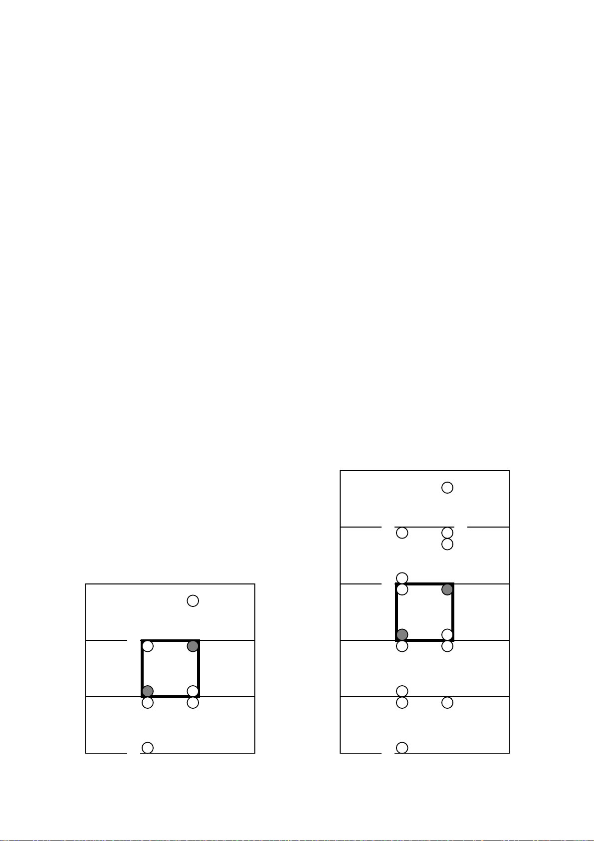
0-1-16
+15
0
-16
-15
+15
Right edge MB
0-1-16
+15
0
-16
-15
+15
-32
+16
+31
-17
+31
+16
-32
SW4 -> 5
All valid
All valid
All valid
Search-Right
All invalid
SW2 -> 3
Search-Left
All valid
SW1 -> 2
All invalid
Search-Right
All valid
All valid
SW1 -> SW2 is used to estimate vectors of -32 ~ -17 (16 points).
SW2 -> SW3 is used to estimate vectors of -16 ~ -1 (16 points).
SW3 -> 4
SW2 -> 3
SW1 -> 2
SW3 -> SW4 is used to estimate vectors of 0 ~ +15 (16 points).
SW4 -> SW5 is used to estimate vectors of +16 ~ +31 (16 points).
However, -32 is invalidated.
MB position
Search-Left
All valid
All valid
All invalid
Search-Left
All valid
All valid
All invalid
All invalid
All valid
Left edge MB
Left edge +1 MB
Normal MB
Right edge -1 MB
All valid
Search-Right
All valid
All valid
All valid
Right edge MB
SW1 -> SW2 is used to estimate vectors of -16 ~ -1 (16 points).
SW2 -> SW3 is used to estimate vectors of 0 ~ +15 (16 points).
However, -16 is invalidated.
Fig. 5.5-2a Horizontal search range control for 2-chips
MB position
Left edge MB
MB1
Normal MB
SW1 SW2 SW3
SW4 SW5
MB1
SW1 SW2 SW3
Fig. 5.5-2b Horizontal search range control for 4-chips

+32 +47 +48 +63
SW8 -> 9
All valid
All valid
SW7 -> 8
All valid
All valid
SW6 -> 7
All valid
All valid
All valid
All valid
All valid
All valid
All valid
All valid
All valid
All valid
All valid
Search-Right
All invalid
All invalid
All invalid
All valid
Search-Right
All invalid
All invalid
All valid
All valid
Search-Right
All invalid
0-1-16 +15
-17 +31+16
-32
-33-49 +47 +63
-48-64
MB1
+16 +31
0
-16 -15 +15
-32
-48-64
SW6 SW7 SW8 SW9
SW4 SW5
SW5 -> 6
Search-Left
All valid
SW4 -> 5
SW3 -> 4
SW2 -> 3
All invalid
All invalid
All invalid
All invalid
All valid
All valid
All valid
All valid
All valid
Search-Left
Search-Left
All valid
All valid
Search-Left
All valid
All valid
All valid
All valid
All invalid
All invalid
Search-Left
All valid
All valid
Search-Right
All valid
All valid
All valid
All valid
All valid
All valid
All valid
All valid
All valid
All valid
Fig. 5.5-2c Horizontal search range control for 8-chips
SW1 -> 2
All invalid
All invalid
All invalid
All invalid
All valid
All valid
All valid
SW1 SW2 SW3
SW1 -> SW2 is used to estimate vectors of -64 ~ -49.
SW2 -> SW3 is used to estimate vectors of -48 ~ -33.
SW3 -> SW4 is used to estimate vectors of -32 ~ -17.
SW4 -> SW5 is used to estimate vectors of -16 ~ -1.
SW5 -> SW6 is used to estimate vectors of 0 ~ +15.
SW6 -> SW7 is used to estimate vectors of +16 ~ +31.
SW7 -> SW8 is used to estimate vectors of +32 ~ +47.
SW8 -> SW9 is used to estimate vectors of +48 ~ +63.
MB position
Left edge MB
Left edge +1 MB
Left edge +2 MB
Left edge +3 MB
Normal MB
All valid
All valid
Right edge -3 MB
Right edge -2 MB
Right edge -1 MB
Right edge MB

-16-10
+15
+16
-16
-150+1
+16
-8-10+7+8-8-70+1
+8
ME#1
ME#1
Fig. 5.5-1b Vertical search range control for 1-chip
One chip estimates vectors of -7.5 ~ +7.5
in non-expansion mode.
One chip estimates vectors of -8.0 ~ +8.0
in vertical expansion mode.
One chip estimates vectors of -15.5 ~ +15.5
in non-expansion mode.
One chip estimates vectors of -16.0 ~ +16.0
in vertical expansion mode.
MB position
Top edge MB
Normal MB
Bottom edge MB
ME#1
Search-Top
All valid
Search-Bottom

Fig. 5.5-1c Vertical search range control for 1-chip
t_-8
b_-8
t_-4
b_-4
t_0
b_0
t_-4
b_-4
t_0
b_0
t_+8
b_+8
t_+4
b_+4
t_+4
b_+4
t_0
b_0
t_+4
b_+4
t_+4
b_+4
t_+4
b_+4
t_0
b_0
t_+8
b_+8
t_+4
b_+4
t_+8
b_+8

0-1-16
+150-16
-15
+15
MB1
SW1
SW2
SW3
SW4
SW5
-32
+16
+31
-17
+31
+16
-32
-48
-64
-48
-64
-33
-49
+47
+63
+32
+47
+48
+63
SW6
SW7
SW8
SW9
Fig. 5.5-2d Horizontal search range control for 16-chips
SW10
SW11
SW12
SW13
SW14
SW15
SW16
SW17
-80
-80
-65
-96
-96
-81
-112
-112
-97
-128
-128
-113
+79
+64
+79
+95
+80
+95
+111
+96
+111
+127
+112
+127
SW16 -> 17
All valid
All valid
SW15 -> 16
All valid
All valid
SW14 -> 15
All valid
All valid
SW13 -> 14
All valid
All valid
SW12 -> 13
All valid
All valid
SW11 -> 12
All valid
All valid
SW10 -> 11
All valid
All valid
All valid
All valid
All valid
All valid
All valid
All valid
All valid
All valid
All valid
All valid
All valid
All valid
All valid
All valid
All valid
All valid
All valid
All valid
All valid
All valid
All valid
All valid
All valid
All valid
All valid
All valid
All valid
All valid
All valid
All valid
All valid
All valid
All valid
All valid
All valid
All valid
All valid
All valid
All valid
All valid
All valid
All valid
All valid
Search-R
All valid
All valid
All valid
All valid
All valid
All valid
All valid
All valid
All valid
All valid
All valid
All valid
All invalid
All invalid
All invalid
Search-R
All invalid
All invalid
All valid
Search-R
All invalid
All valid
All valid
Search-R
All valid
All valid
All valid
All valid
All valid
All valid
All valid
All valid
All valid
All invalid
All invalid
All invalid
All invalid
All invalid
All invalid
All invalid
All invalid
All invalid
All invalid
All invalid
All invalid
Search-R
All invalid
All invalid
All valid
Search-R
All invalid
All valid
All valid
Search-R
All invalid
All invalid
All invalid
All invalid
All invalid
All invalid
All invalid
SW9 -> 10
Search-L
All valid
All valid
All valid
All valid
All valid
All valid
All valid
SW8 -> 9
All invalid
Search-L
All valid
All valid
All valid
All valid
All valid
All valid
SW9 -> SW10 is used to estimates vectors of 0 ~ +15.
SW10 -> SW11 is used to estimates vectors of +16 ~ +31.
SW11 -> SW12 is used to estimates vectors of +32 ~ +47.
SW12 -> SW13 is used to estimates vectors of +48 ~ +63.
SW13 -> SW14 is used to estimates vectors of +64 ~ +79.
SW14 -> SW15 is used to estimates vectors of +80 ~ +95.
SW15 -> SW16 is used to estimates vectors of +96 ~ +111.
SW16 -> SW17 is used to estimates vectors of +112 ~ +127.
However, -128 is invalidated.
SW7 -> 8
All invalid
All invalid
Search-L
All valid
All valid
All valid
All valid
All valid
SW6 -> 7
All invalid
All invalid
All invalid
Search-L
All valid
All valid
All valid
All valid
SW5 -> 6
All invalid
All invalid
All invalid
All invalid
Search-L
All valid
All valid
All valid
SW4 -> 5
All invalid
All invalid
All invalid
All invalid
All invalid
Search-L
All valid
All valid
SW3 -> 4
All invalid
All invalid
All invalid
All invalid
All invalid
All invalid
Search-L
All valid
SW2 -> 3
All invalid
All invalid
All invalid
All invalid
All invalid
All invalid
All invalid
Search-L
SW1 -> SW2 is used to estimates vectors of -128 ~ -113.
SW2 -> SW3 is used to estimates vectors of -112 ~ -97.
SW3 -> SW4 is used to estimates vectors of -96 ~ -81.
SW4 -> SW5 is used to estimates vectors of -80 ~ -65.
SW5 -> SW6 is used to estimates vectors of -64 ~ -49.
SW6 -> SW7 is used to estimates vectors of -48 ~ -33.
SW7 -> SW8 is used to estimates vectors of -32 ~ -17.
SW8 -> SW9 is used to estimates vectors of -16 ~ -1.
All valid
All valid
All valid
All valid
All valid
All valid
All valid
All valid
All valid
All valid
All valid
All valid
All valid
All valid
All valid¯
All valid
All valid
All valid
All valid
All valid
All valid
All valid
All valid
All valid
All valid
All valid
All valid
All valid
All valid
All valid
All valid
All valid
All valid
All valid
All valid
All valid
All valid
All valid
All valid
All valid
All valid
All valid
All valid
All valid
All valid
All valid
All valid
All valid
All valid
All valid
All valid
All valid
All valid
All valid
All valid
All valid
All valid
All valid
All valid
All valid
All valid
All valid
All valid
All valid
Search-R
All valid
All valid
All valid
All valid
All valid
All valid
All valid
SW1 -> 2
MB position
All invalid
All invalid
All invalid
All invalid
Left edge MB
Left edge +1 MB
Left edge +2 MB
Left edge +3 MB
All invalid
All invalid
All invalid
All invalid
All valid
Left edge +4 MB
Left edge +5 MB
Left edge +6 MB
Left edge +7 MB
Normal MB
All valid
All valid
All valid
All valid
All valid
All valid
Right edge -7 MB
Right edge -6 MB
Right edge -5 MB
Right edge -4 MB
Right edge -3 MB
Right edge -2 MB
All valid
All valid
Right edge -1 MB
Right edge MB

Fig. 5.5-3c Vertical search range control for 2-chips
t_-8
b_-8
t_-4
b_-4
t_0
b_0
t_+4
b_+4
t_-8
b_-8
t_-4
b_-4
t_-4
b_-4
t_0
b_0
t_+4
b_+4
t_-4
b_-4
t_0
b_0
t_-4
b_-4
t_0
b_0
t_+8
b_+8
t_0
b_0
t_+4
b_+4
t_+8
b_+8
ME#1
t_+4
b_+4
t_-4
b_-4
t_+4
b_+4
t_0
b_0
t_+4
b_+4
ME#2

-32-10
+15
+16
+31
+32
-16
-15
-31
-320+1
+31
-16-10
+15
+16
-16
-150+1
+16
-16-10
+15
+16
-16
-150+1
+16
ME#1
ME#2
-16
Fig. 5.5-3d Vertical search range control for 2-chips
All chips are operated in expansion mode.
ME#1 estimates vectors of -32.0 ~ 0.0.
ME#2 estimates vectors of 0.0 ~ +32.0.
So, the total search range is -32.0 ~ +32.0
MB position
Top edge MB
Top edge +1 MB
Normal MB
Bottom edge -1 MB
Bottom edge MB
ME#1
All invalid
Search-Top
All valid
All valid
All valid
ME#2
All valid
All valid
All valid
Search-Bottom
All invalid

t_-16
Fig. 5.5-3f Vertical search range control for 2-chips
b_-16
t_-8
b_-8
t_-12
b_-12
t_-8
b_-8
t_-4
b_-4
t_0
b_0
t_+4
b_+4
t_-16
b_-16
t_-8
b_-8
t_-4
b_-4
t_-4
b_-4
t_0
b_0
t_+4
b_+4
t_+8
b_+8
t_-8
b_-8
t_-4
b_-4
t_0
b_0
t_+4
b_+4
t_-8
b_-8
t_-4
b_-4
t_+8
b_+8
t_+16
b_+16
t_0
b_0
t_+4
b_+4
t_+8
b_+8
t_+12
b_+12
t_+16
b_+16
ME#1
t_+8
b_+8
t_0
b_0
t_+4
b_+4
t_+8
b_+8
ME#2
t_-8
b_-8
t_-4
b_-4
t_0
b_0
t_+4
b_+4
t_+8
b_+8

SW4 SW5 SW6 SW7
IU processing /
X
X
X
X
X
MB1
MB2
MB3
MB4
MB5
MB6
MB7
MB8
cycle
Fig. 5.6-1a Operation timing for 1-chip (vertical search range = ±7.5)
T = Search-Top, B = Search-Bottom, L = Search-Left, R = Search-Right, Nom. = All valid
nSW1
SW7 SW8 SW9
MB4 MB5 MB6
MB7 MB8 MB9
nSW4
nSW3
nSW2
nSW1
SW9
SW8
SW7
SW6
nMB3
nMB2
nMB1
MB9
MB8
MB7
MB6
MB5
T, R
T
T, L
B, R
B
B, L
R
Nom.
nSW3
nSW2
nSW1
SW9
SW8
SW7
SW6
SW5
nMB2
nMB1
MB9
MB8
MB7
MB6
MB5
MB4
T
T, L
B, R
B
B, L
R
Nom.
L
MB9
MB8
MB7
MB6
MB5
MB4
MB3
MB2
SW1 SW2 SW3 SW4
MB2 MB3
MB1
MB2 MB3
MB1
MB4 MB5 MB6
MB7 MB8 MB9
SW5
SW4
SW3
SW2
SW1
1 execution
SW input
MB4
L
MB3
T, R
MB2
T
MB1
T, L
X
X
MB input
D-cont. input
SW4
MB3
T, R
SW3
MB2
T
SW2
MB1
T, L
SW1
X
X
X
X
X
SW array input
MB1
X
X
X
X

MB1
MB2
MB3
MB4
MB5
MB6
MB7
MB8
MB9
SW1
SW2
SW3
SW4
SW4
SW5
SW6
SW7
SW7
SW8
SW9
nSW1
MB1
MB2
MB3
MB4
MB5
MB6
MB7
MB8
MB9
SW1
X
X
X
X
X
X
X
SW2
MB1
T, L
SW1
X
X
X
X
SW3
MB2
T
SW2
MB1
T, L
X
X
SW4
MB3
T, R
SW3
MB2
T
X
X
SW5
MB4
L
SW4
MB3
T, R
MB1
X
SW6
MB5
Nom.
SW5
MB4
L
MB2
MB1
SW7
MB6
R
SW6
MB5
Nom.
MB3
MB2
SW8
MB7
B, L
SW7
MB6
R
MB4
MB3
SW9
MB8
B
SW8
MB7
B, L
MB5
MB4
nSW1
MB9
B, R
SW9
MB8
B
MB6
MB5
nSW2
nMB1
T, L
nSW1
MB9
B, R
MB7
MB6
nSW3
nMB2
T
nSW2
nMB1
T, L
MB8
MB7
nSW4
nMB3
T, R
nSW3
nMB2
T
MB9
MB8
1 execution
cycle
Fig. 5.6-1b Operation timing for 1-chip (vertical search range = ±15.5)
Output
T = Search-Top, B = Search-Bottom, L = Search-Left, R = Search-Right, Nom. = All valid
SW input
MB input
D-cont. input
SW array input
IU processing MB
IU cont.
HU processing MB

MB1
MB2
MB3
MB4
MB5
MB6
MB7
MB8
MB9
SW1
SW2
SW3
SW4
SW5
SW6
SW7
SW8
MB1
MB2
MB3
MB4
MB5
MB6
MB7
MB8
MB9
X
X
X
1 execution
cycle
X
X
X
MB2
-
MB4
-
MB6
-
MB8
-
nSW6
nMB1
Output
T = Search-Top, B = Search-Bottom, L = Search-Left, R = Search-Right, Nom. = All valid, Inv. = All invalid
nMB6
Nom.
nSW5
nMB4LnMB2
-
nSW6-Nom.
nSW5
nMB3
Nom.
-
nSW5-L
nSW4
nSW3-T
nSW2
nSW1-B, R
SW9
SW8-B, L
nSW4
nMB4
Inv.
nSW3
nSW2
nMB2TnSW1
SW9
MB9BSW8
SW7
nMB4
Inv.-MB9
nMB2TMB9
nMB2T-
MB9
MB9B-
MB7
MB7
-
MB7
B, R
MB7
-
MB5
B, L
MB5
-
Inv.-MB3
nSW5
nMB5
Nom.
nSW4
nSW4-T, R
nSW3
nSW2-T, L
nSW1
SW9-B
SW8
nSW3
nMB3TnSW2
nSW1
nMB1
Inv.
SW9
SW8
MB8BSW7
nMB3
T, R
nMB1
nMB3T-
nMB1
T, L
MB8
nMB1
Inv.
-
MB8BMB6
MB8B-
MB6RMB4
SW7
MB7
Inv.
SW6
SW6-Nom.
SW5
SW4-T, R
SW3
SW2-T, L
SW1
SW5
MB5
Nom.
SW4
SW3
MB3TSW2
SW1
MB1
Inv.XXXX
MB5
Nom.
MB3
MB5
Nom.-MB1
MB3
T, R
MB1
MB3TX
MB1
T, LXX
MB1
Inv.XX
-
X
X
X
SW7-R
SW6
SW5-L
SW4
SW3-T
SW2
SW6
MB6
MB6
Nom.
SW5
MB4LMB2
SW4
MB4
MB4
Inv.
SW3
MB2TX
SW2
MB2TX
MB2TSW1XX
SW1XXXX
Nom.
-
Inv.
X
X
X
X
Fig. 5.6-1c Operation timing for horizontal 2-chips expansion (vertical search range = ±15.5)
ME#1
SW input
MB input
D-cont. input
SW array input
IU processing MB
IU cont.
HU processing MB
Output
ME#2
SW input
MB input
D-cont. input
SW array input
IU processing MB
IU cont.
HU processing MB
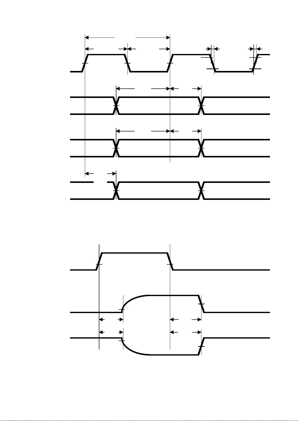
twh(CLK)
Fig. 6.1.5-1 Timing Diagram
tc(CLK)
twl(CLK)
tf(CLK)
tr(CLK)
CLKI
DATA(*)
CONTROL(*)
DOUT<7:0>
50%
tpLH
tpHL
50%
50%
50%
50%
tsu(D)
tsu(C)
50%
th(D)
th(C)
90%
10%
90%
10%
50%
50%
50%
(*)
OEC
DOUT<7:0>
DATA : DSWI<31:0>, DMBI<7:0>
CONTROL : Input Pins without DSWI, DMBI, CLKI, OEC
1.3V
10%
tPLZ
tPHZ
90%
1.3V
50%
tPZL
tPZH
50%
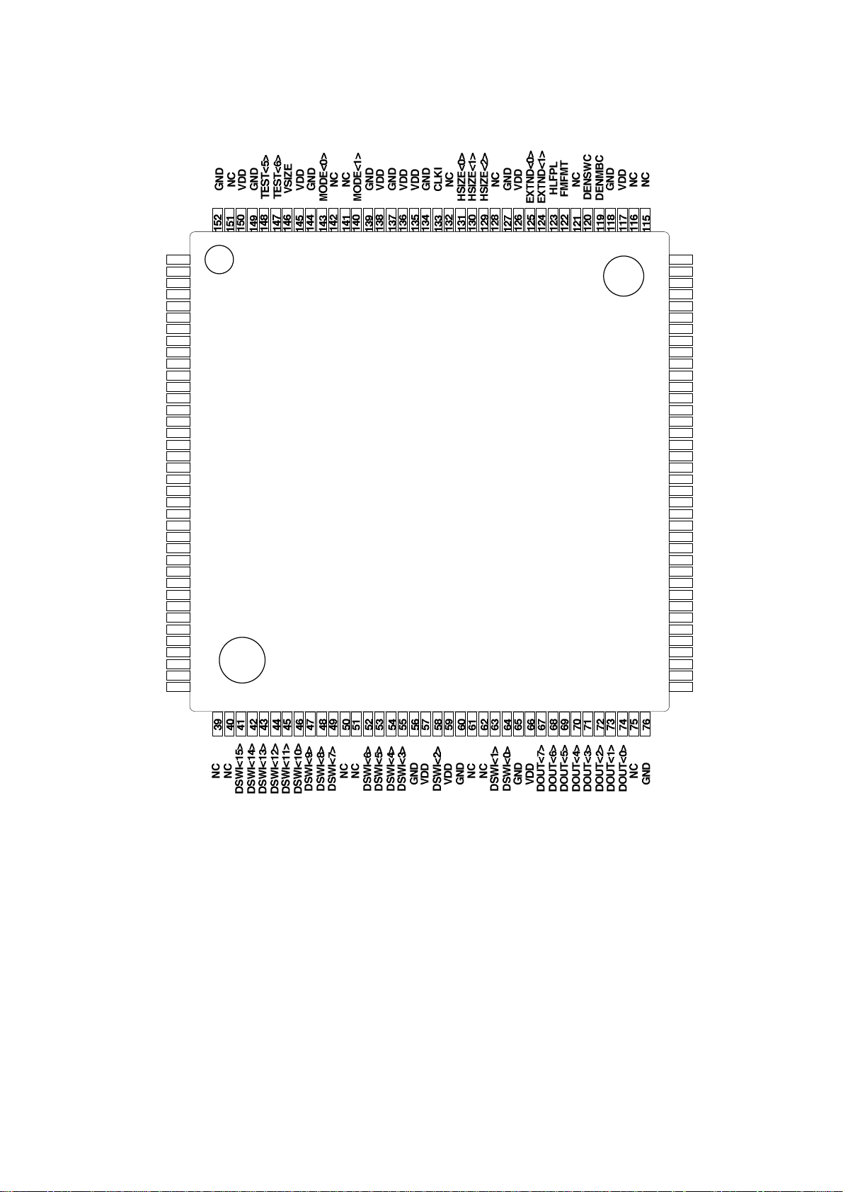
Fig. 6.2-2 Pin Configuration of M65727FP
NC
1234567891011121314151617181920212223242526272829303132333435363738114
112
110
108
106
104
102
10099989796959493929190898887868584838281807978
TEST<4>
TEST<3>
TEST<2>
TEST<1>
TEST<0>
DSWI<31>
DSWI<30>
DSWI<29>
DSWI<28>
DSWI<27>
NC
DSWI<26>
DSWI<25>
DSWI<24>
DSWI<23>
DSWI<22>
NC
DSWI<21>
DSWI<20>
NC
DSWI<19>
GND
VDD
GND
NC
NC
VDD
VDD
GND
NC
DSWI<18>
DSWI<17>
DSWI<16>
GND
VDD
NC
GND
113
111
109
107
105
103
101
77
GND
DCNT<0>
DCNT<1>
DCNT<2>
DCNT<3>
DMBI<0>
DMBI<1>
DMBI<2>
DMBI<3>
DMBI<4>
DMBI<5>
DMBI<6>
DMBI<7>
NC
VDD
GND
VDD
NC
GND
NC
RESETC
VDD
NC
GND
CEC
OREQC
VDD
GND
MSYNC
ESYNC
SSYNC
DSYNC
OEC
VDD
GND
NC
NC
NC

Table 6.2-1 Pin Configuration of M65727FP
Pin number Pin name Pin number Pin name Pin number Pin name Pin number Pin name
1 NC 39 NC 77 NC 115 NC
2 TEST<4> 40 NC 78 NC 116 NC
3 TEST<3> 41 DSWI<15> 79 NC 117 VDD
4 TEST<2> 42 DSWI<14> 80 GND 118 GND
5 TEST<1> 43 DSWI<13> 81 VDD 119 DENMBC
6 TEST<0> 44 DSWI<12> 82 OEC 120 DENSWC
7 DSWI<31> 45 DSWI<11> 83 DSYNC 121 NC
8 DSWI<30> 46 DSWI<10> 84 SSYNC 122 FMFMT
9 DSWI<29> 47 DSWI<9> 85 ESYNC 123 HLFPL
10 DSWI<28> 48 DSWI<8> 86 MSYNC 124 EXTND<1>
11 DSWI<27> 49 DSWI<7> 87 GND 125 EXTND<0>
12 NC 50 NC 88 VDD 126 VDD
13 DSWI<26> 51 NC 89 OREQC 127 GND
14 DSWI<25> 52 DSWI<6> 90 CEC 128 NC
15 DSWI<24> 53 DSWI<5> 91 GND 129 HSIZE<2>
16 DSWI<23> 54 DSWI<4> 92 NC 130 HSIZE<1>
17 DSWI<22> 55 DSWI<3> 93 VDD 131 HSIZE<0>
18 NC 56 GND 94 RESETC 132 NC
19 DSWI<21> 57 VDD 95 NC 133 CLKI
20 DSWI<20> 58 DSWI<2> 96 GND 134 GND
21 NC 59 VDD 97 NC 135 VDD
22 DSWI<19> 60 GND 98 VDD 136 VDD
23 GND 61 NC 99 GND 137 GND
24 VDD 62 NC 100 VDD 138 VDD
25 GND 63 DSWI<1> 101 NC 139 GND
26 NC 64 DSWI<0> 102 DMBI<7> 140 MODE<1>
27 NC 65 GND 103 DMBI<6> 141 NC
28 VDD 66 VDD 104 DMBI<5> 142 NC
29 VDD 67 DOUT<7> 105 DMBI<4> 143 MODE<0>
30 GND 68 DOUT<6> 106 DMBI<3> 144 GND
31 NC 69 DOUT<5> 107 DMBI<2> 145 VDD
32 DSWI<18> 70 DOUT<4> 108 DMBI<1> 146 VSIZE
33 DSWI<17> 71 DOUT<3> 109 DMBI<0> 147 TEST<6>
34 DSWI<16> 72 DOUT<2> 110 DCNT<3> 148 TEST<5>
35 GND 73 DOUT<1> 111 DCNT<2> 149 GND
36 VDD 74 DOUT<0> 112 DCNT<1> 150 VDD
37 NC 75 NC 113 DCNT<0> 151 NC
38 GND 76 GND 114 GND 152 GND
 Loading...