

Mitsubishi M57140-01 Datasheet
MITSUBISHI HYBRID ICs
M57140-01
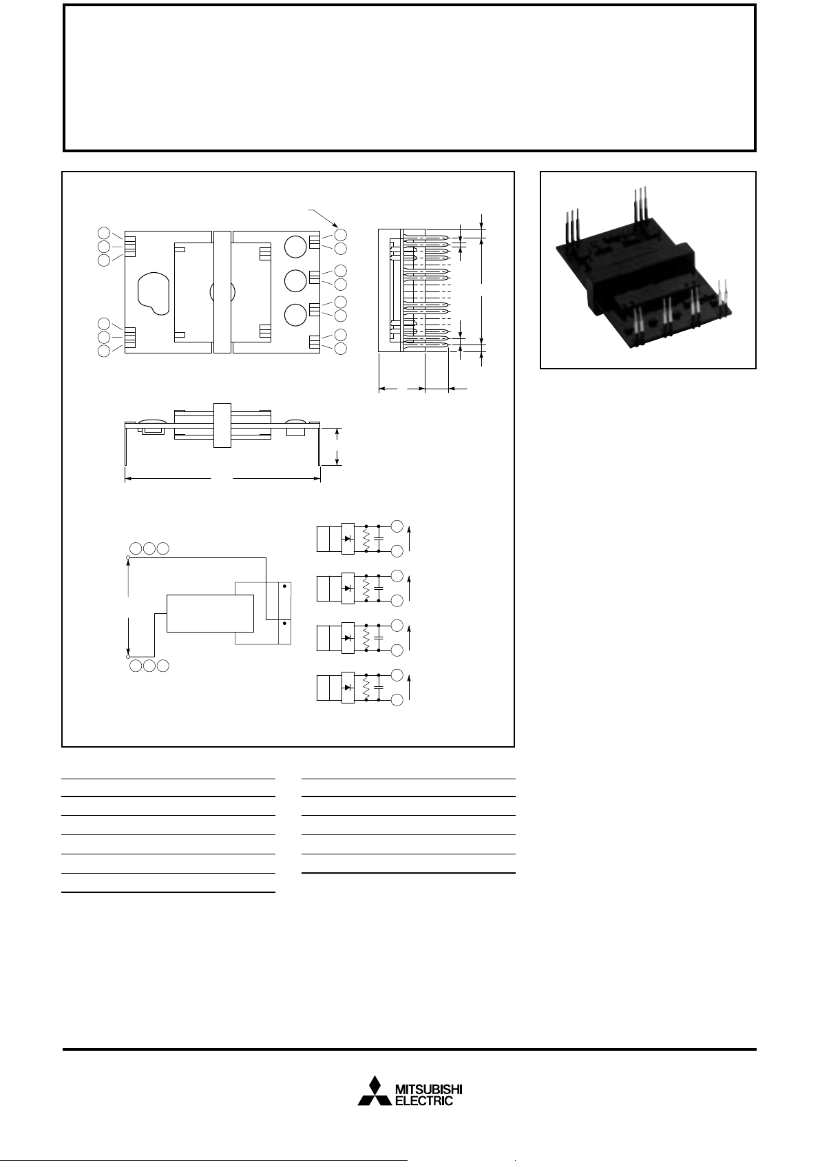
IPM POWER SUPPLY HYBRID IC
1
2
3
4
5
6
INPUT
DC 20V
4 5 6
, ,
1 2 3
, ,
TERMINAL NUMBER
A
PUSH-PULL
CONVERTER
CONTROL CIRCUIT
H
14
13
12
11
10
9
8
7
B
F
J
E
G
D
Description:
M57140-01 is an isolated DC-to-DC
converter designed to drive IPMs
C
(Intelligent Power Modules). With
an input of DC 20V, the module
supplies four 15V outputs. Isolation is provided from primary to
secondary and also between the
14
13
12
11
10
9
8
7
OUT PUT
15V, 30mA
OUT PUT
15V, 30mA
OUT PUT
15V, 30mA
OUT PUT
15V, 100mA
secondaries. Interwinding isolation
is designed for driving the IPM.
Features::
u Output Specification:
+15V x 4, Total 3W max.
u Primary-to-secondary Isolation:
2500 V
, One Minute
RMS
u Secondary-to-secondary
Isolation Voltage:
1500 V
, One Minute
RMS
u Compact, Low Profile Design
Outline Drawing and Circuit Diagram
Dimensions Inches Millimeters
A 2.03 51.5
B 0.71 18.0 MAX
C .39±.06 12.5±1.5
D .18±.06 4.5±1.5
E 0.07 1.8
Dimensions Inches Millimeters
F 0.02 0.55
G 0.08 2.1
H 0.08 2.1
J 1.13 28.8
Applications:
u IPMs for General Purpose
Inverter and AC Servo
u Power Source for MOSFET
Driving Circuits
Ordering Information:
M57140-01
Sep.1998

MITSUBISHI HYBRID ICs
M57140-01
IPM POWER SUPPLY HYBRID IC
Absolute Maximum Ratings, VIN = 20V, Ta = 25 °C unless otherwise specified
Characteristics Symbol Test Conditions M57140-01 Units
Input Voltage V
Load Current I
Operating T emperature T
Storage Temperature T
Internal Power Dissipation P
IN
L
opr
stg
d
Primary-to-Secondary Isolation 1 Minute 2500 V
Secondary-to-Secondary Isolation 1 Minute 1500 V
Electrical Characteristics, VIN = 20V, Ta = 25 °C unless otherwise specified
Characteristics Symbol Test Conditions Min. Typ. Max. Units
Input Source Voltage V
Output Voltage V
Peak Load Current I
Load Regulation Reg-out – 5 10 %
Efficiency η –70–%
IN
O
LP
Terminals 4 , 5 , 6 - 1 , 2 , 3
Terminals 14 - 13 , 12 - 11 , 10 - 9
Terminals 8 - 7
There Should be -10 ~ +75 °C
No Condensation -20 ~ +85 °C
– 1.5 Watts
Direct Current 18 20 22 Volts
Between Pins 10 - 9 , 12 - 11, 14 - 13,
= 30mA
I
L
Between Pins 8 - 7 , I
= 100mA
L
Between Pins 10 - 9 , 12 - 11, 14 - 13
Between Pins 8 - 7
Between Pins 10 - 9 , 12 - 11, 14 - 13,
= 0 ~ 30mA
I
L
Between Pins 8 - 7 , I
= 0 ~ 100mA
L
Between Pins 10 - 9 , 12 - 11, 14 - 13,
= 30mA
I
L
Between Pins 8 - 7 , I
= 100mA
L
25 Volts
30 mA
100 mA
rms
rms
13.5 15.0 16.5 Volts
13.5 15.0 16.5 Volts
–33–mA
– 110 – mA
– 7 12 %
–70–%
Application Circuit
8
+
V
I
C
33µF
7
4 5 6
, ,
+
V
= 20V
330µF
IN
M57140-01
1 2 3
, ,
10
10µF
9
12
10µF
11
14
10µF
13
L
+
V
I
C
L
+
V
I
C
L
+
V
I
C
L
Sep.1998
 Loading...