

Mitsubishi M54677FP Datasheet
MITSUBISHI <CONTROL / DRIVER IC>
)
M54677FP
2-PHASE STEPPER MOTOR DRIVER
DESCRIPTION
The M54677FP is a semiconductor IC to drive a bipolar stepper
motor directly by controlling the coil current with the constant
current method.
FEATURES
●Wide output current control range (20 – 1000mA)
● Bipolar and constant current
●Built in a thermal shutdown circuit
●Built in flywheel diodes
APPLICATION
Office automation equipment such as printer, FDD, HDD, and FAX
FUNCTION
The M54677FP can drive a stepper motor by the 2-phase bipolar
method and also control the coil current. Furthermore, it controls
the direction of the coil current by Ph input and the coil current
value by Vref pin.
Because two control circuits are built in this IC, a stepper motor
can be driven with a single IC by the 2-phase bipolar method.
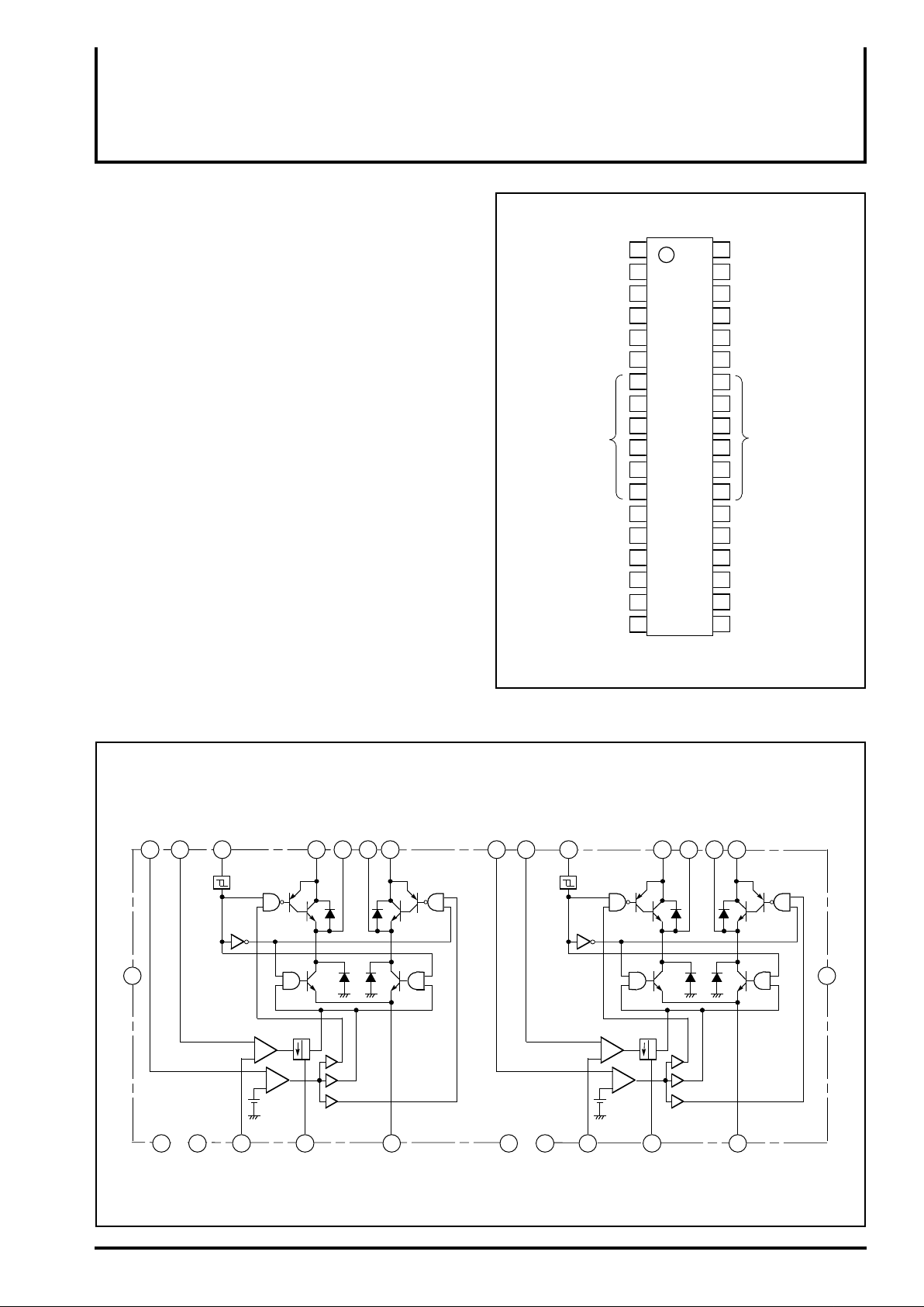
PIN CONFIGURATION(TOP VIEW
36
35
34
33
325
316
30
M54677FP
29
289
2710
2611
2512
24
23
21
20
19
GND
1
St1
2
C1
3
Vref1
4
VM11
A1
M
E1
7
8
13
N.C
14
B1
M
15 22
VM12
16
Vcc1
17
T1
Ph1
18
Outline 36P2R-D
St2
C2
Vref2
V
M21
MA2
E2
GND
N.C
M
B2
VM22
Vcc2
T2
Ph2
N.C: no connection
BLOCK DIAGRAM
St2
Vref2
34
36
21
Vcc2
25 30
GND C2 T2 E2 GND C1 T1 E1
19 33 32 23 22
current
-comp
–
Ph2
35
mono-multi
+
–
–
+
standby
-comp
St1
Vref1
VM21
MA2
MB2
VM22
1 3
Buffer
20
31
7
–
Ph1
18 4 5 14 15
current
-comp
12 2
mono-multi
+
–
–
+
standby
-comp
VM11
Buffer
17 6
MA1
MB1
VM12
16
Vcc1
MITSUBISHI <CONTROL / DRIVER IC>
M54677FP
2-PHASE STEPPER MOTOR DRIVER
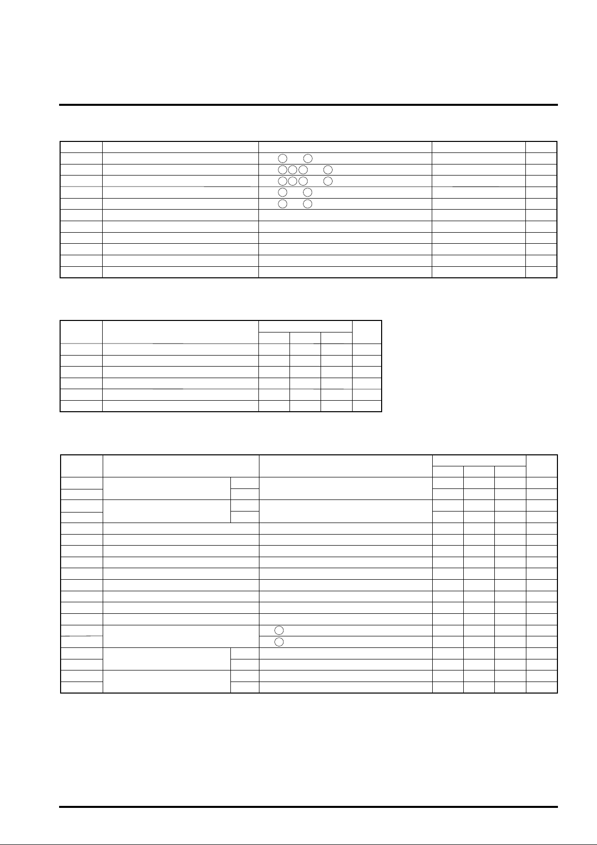
ABSOLUTE MAXIMUM RATINGS(Ta=25˚C, unless otherwise noted)
Symbol Ratings
Vcc -0.3 – 7
VM
VL
Vc -0.3 – Vcc
Vref
I
O
Pd
Kθ
Tj
Topr
Tstg
Supply voltage
Output supply voltage
Logic input voltage
Analog input voltage
Comparative input voltage
Output current
Allowable loss
Thermal derating
Junction temperature
Operating temperature
Storage temperature
RECOMMENDED OPERATING CONDITIONS
Symbol
Vcc
VM
Io
tPLH
tPHL
Ton
Small-signal supply voltage
Output supply voltage
Output current
Logic input rise time
Logic input fall time
Thermal shutdown temperature
Parameter Conditions
16 21
Pins and
4 15 33 32
36 18 191
2 35
Limits
Typ.
500
160
and
and
343
Max.
5.5
1000
2
2
Pins
Pins
Pins and
Pins and
Mounted on a glass epoxy board (100mm x 100mm, t=1.6mm)
Mounted on a glass epoxy board (100mm x 100mm, t=1.6mm)
Min.
10 26.5
-0.3 – 28
-0.3 – 6
-0.3 – Vcc
1500
2.0
62.5
150
-20 – 75
-40 – 125
UnitParameter
V5.04.5
V
mA
µS
µS
˚C
Unit
V
V
V
V
V
mA
W
˚C/W
˚C
˚C
˚C
ELECTRICAL CHARACTERISTICS(Ta=25˚C, Vcc=5V, VM=24V, unless otherwise noted)
Symbol Test conditions UnitParameter
VIH
VIL
VIH
VIL
VCH
IC
VC
Iref
Vref
IOFF
Vsat
tOFF
td
Icc1
Icc2
IIH
IIL
IIH
IIL
Logic input voltage (St pin)
Logic input voltage (Ph pin)
Comparator input offset voltage
Comparator input current
Comparator input voltage range
Vref input current
Vref input voltage range
Output cutoff current
Saturation voltage
Cutoff time
Output turnoff delay
Supply current
Logic input current (St pin)
Logic input current (Ph pin)
“H”
Vcc=5V
“L”
“H”
Vcc=5V
“L”
Vref = 500mV
C pin input current (C=0V, Vref=500mV)
Vref pin input current (Vref=0V, C=500mV)
Voltage at sensing resistor is not included. Io=0.5A
16
Pin current (16Pin=5V)
21
Pin current (21Pin=5V)
“H”
Vin = 5V
“L”
Vin = 0V
“H”
Vin = 5V
“L”
Vin = 0V
Min. Typ. Max.
2.0
0
2.0
0
-4
-20
0
-20
0
5
-200
-200
Limits
2
-5
-5
1.3
27
1.6
27
26
Vcc
0.6
Vcc
0.8
8
1.5
1.5
100
1.8
50
2.0
40
39
10
10
V
V
V
V
mV
µA
V
µA
V
µA
V
µS
µS
mA
mA
µA
µA
µA
µA
 Loading...