

Mitsubishi M54670P Datasheet
MITSUBISHI <CONTROL / DRIVER IC>
(A)
g
)
)
)
y(A)
(A)
(B)
g(B)
y(B)
g
g
)
M54670P
2-PHASE STEPPER MOTOR DRIVER
DESCRIPTION
The M54670P is a semiconductor IC to drive a bipolar stepper
motor directly by controlling the coil current with the constant
current method.
FEATURES
● Wide operating voltage range (10 – 35V)
● Wide output current control range (20 – 800mA)
● Bipolar and constant current drive
● Built in flywheel
● Current level can be changed by steps or continuously.
● Built in a thermal shutdown circuit
APPLICATION
Office automation equipment such as printer, FDD, HDD, and FAX
FUNCTION
The M54670P can drive a stepper motor by the 2-phase bipolar
method and also control the coil current. Furthermore, it controls
the direction of the coil current with Ph input pins (pins 3 and 30).
The coil current value can be selected among four levels (0 to
max.) by selecting the combination of three internal comparators by
logic input (pins 14, 15, 18 and 19). It also can be continuously
controlled with VR pins (pins 2 and 31). By selecting an I input pin
among pins 14, 15, 18 or 19, the operation timing, 2-phase
excitation, 1-2-phase excitation or microstep, can be selected.
Because two control circuits are built in this IC, a stepper motor can
be driven with a single IC by the 2-phase bipolar method.
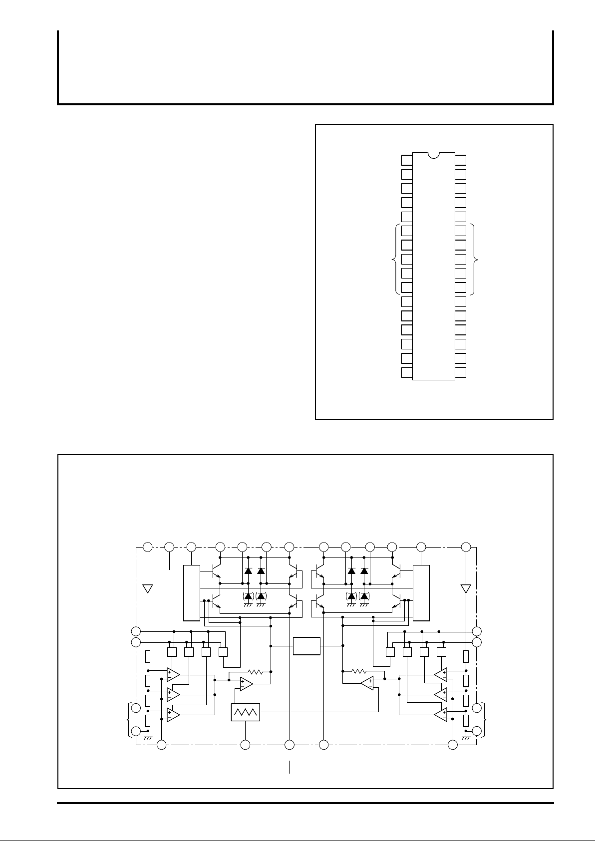
PIN CONFIGURATION(TOP VIEW
Triangular wave
Comparator
reference input
Output current
direction switchin
Output power
supply(A)
Output(A
Current sensor(A
Output(A
Output power
suppl
Output current
value setting(A)
Output current
value setting(A)
Comparator
input
(A)
VR(A)
Ph(A)
MM1(A)
V
O1(A)
GND
O2(A)
MM2(A)
V
CT
E(A)
I0(A)
I1(A)
C(A)
10
11
12
13
14
15
16
1
2
3
4
5
6
7
M54670P
8
9
Outline 32P4B
32
31
30
29
28
27
26
25
24
23
22
21
20
19
18
17
CC
V
VR(B)
Ph(B)
MM1(B)
V
O1(B)
E(B)
O2(B)
V
MM2(B)
I0(B)
I1(B)
C(B)
GND
Circuit power supply
Comparator
reference input
Output current
direction switchin
Output power
suppl
Output(B)
Current sensor(B)
Output(B)
Output power
supply(B)
Output current
value settin
Output current
value settin
Comparator
input(B)
(B)
(B)
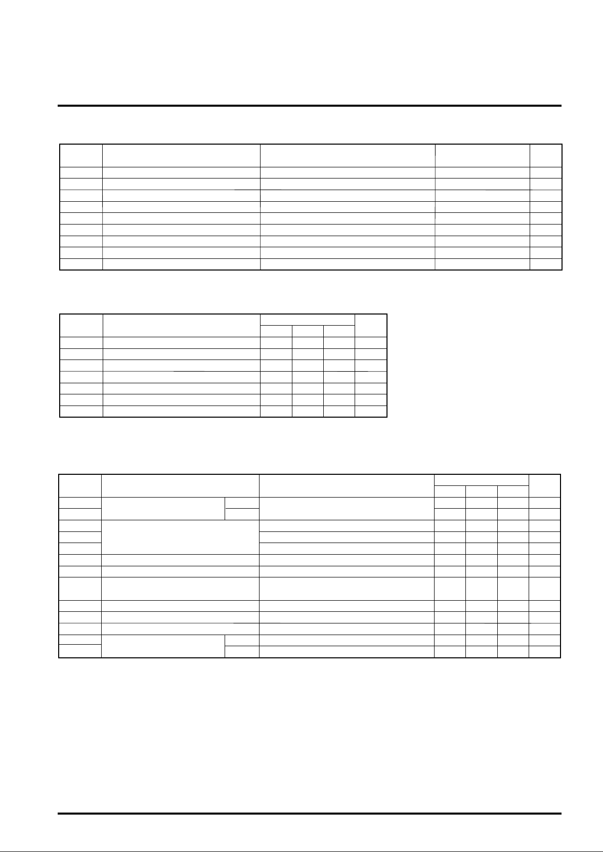
BLOCK DIAGRAM
VR(A)
Output current value
Output current value
setting(A)
I0(A)
setting(A)
I1(A)
GND
14
15
6
–
10
Comparator input(A) Triangular wave
h(A)
CC Circuit power supply
Comparator
reference input(A)
V
2
32
P
MM1(A)
Output current
direction switching(A)
Output power supply(A)
V
3 4 5
Output(A)
O1(A)
MM2(A)
Output(A)
O2(A)
V
12 13 29 28 21 20 30 31
Output power supply(A)
MM1(B)
Output power supply(B)
V
Output(B)
O1(B)
Output(B)
O2(B)
Control circuit
TSD
00 10 01 11 11 01 10 00
Power supply sensor
16
C(A)
Triangular
wave
1
CT
11
E(A)
22
E(B)
Power supply sensor
Current sensor(B) Comparator input(B)
MM2(B)
V
Output power supply(B)
h(B)
Output current
direction switching(B)
P
Control circuit
17
C(B)
R(B)
Comparator input(B)
V
Output current value
setting(B)
19
I0(B)
18
Output current value
setting(B)
I1(B)
23
GND
–
27
Current sensor(A)
MITSUBISHI <CONTROL / DRIVER IC>
ABSOLUTE MAXIMUM RATINGS (Ta=25°C, unless otherwise noted)
Symbol Ratings UnitParameter Conditions
M54670P
2-PHASE STEPPER MOTOR DRIVER
VCC
VMM
VI
VC
VR
IO
Pd
Topr
Tstg
Supply voltage
Output supply voltage
Logic circuit input voltage
Comparator input voltage
Reference input voltage
Output current
Allowable power dissipation
Operating temperature
Storage temperature
Mounted on a board
-0.3 – 7
-0.3 – 40
-0.3 – 6
-20 – 75
-55 – 125
RECOMMENDED OPERATING CONDITIONS (VCC=5.0V, Ta=25°C, unless otherwise noted)
Symbol
VCC
V
MM
VR
IO
tPLH
tPHL
TON
* : Refer to "PRECAUTIONS FOR USE."
Supply voltage
Output supply voltage
Reference input voltage
Output current
Logic input rise time
Logic input fall time
Thermal shutdown temperature *
Parameter
Limits
Min. Typ. Max.
10
0
20
5.00 5.25
35
—
800
4.75
2.0
2.0
175
Unit
V
V
5
V
mA
µs
µs
°C
ELECTRICAL CHARACTERISTICS (VCC=5.0V, VMM=10V, Ta=25°C, unless otherwise noted)
Symbol
VIH
VIL
VCH
VCM
VCL
ICO
IOFF
Vsat
fc
td
ICC
IIH
IIL
Logic input voltage
Comparator threshold
Comparator input current
Output cutoff current
Saturation voltage
PWM oscillator frequency
Turn-off delay
Supply current
Logic input current
Test conditions UnitParameter
“H”
V
“L”
CC=5V
VR=5V, I0=I1=0
V
R=5V, I0=1, I1=0
R=5V, I0=0, I1=1
V
I
0=I1=1(Ta=25°C)
Voltage at sensing resistor is not included.
I
0=500mA
V
MM=10V, Cf=3900pF
Ta=25°C, dV/dt≥50mV/µs
CC=5V
V
“H”
“L”
I=2.4V
V
I=0.4V
V
Limits
Min. Typ. Max.
2.0
0
430
265
90
-20
—
—
16.5
—
—
—
—
V
CC
7
±1.0
1.92
—
V
CC
—
460
285
110
0.8
480
305
130
-2
20
100
0
3.0 4.5 V
33
1.0
8.0
180
20
66
2.0
25
400
50
V
V
V
V
V
A
W
°C
°C
V
V
mV
mV
mV
µA
µA
kHz
µs
mA
µA
µA
 Loading...