

MITSUBISHI <CONTROL / DRIVER IC>
M54649L
DUAL Bi-DIRECTIONAL MOTOR DRIVER
DESCRIPTION
The M54649L is a semiconductor integrated circuit that is capable
of directly driving two smallsize bi-directional motors rotating in
both forward and reverse directions.
FEATURES
● Capable of driving two motors in both forward and reverse
directions
● Equipped with “H” output voltage control pin
● Built-in thermal protection circuit
● Large output current drive (IO(max) = 1.6A)
● Wide range of operating supply voltage (VCC = 4 – 18V)
● Capable of directly driving with CMOS IC output
APPLICATION
Sound equipment such as tape deck and radio cassette, VTR, and
other general consumer appliances
FUNCTION
The M54649L consists of input circuit, control circuit, constant
current circuit and output circuit.
Two motors are connected to the IC; both of them are connected to
output pin O1, and one is connected to output O2, and the other is
connected to output O3. The motors are controlled by three input
levels of input pins IN1 to IN3. As shown in the logic truth table, the
control statuses of ‘forward rotation’, ‘reverse rotation’, ‘brake’ and
‘OFF’ are selectable.
The input circuit provides hysteresis functions that prevent
malfunction due to rounding at rising edge and falling edge of input
signals.
Both the current source side and sink side of the output circuit
adopt Darlington circuit configuration of the NPN transistor,
allowing up to ±1.6A output current to flow.
In addition, the IC contains a thermal protection circuit to put all
outputs in the “OPEN” mode for preventing the IC from thermal
braking when failures such as motor lock occurs.
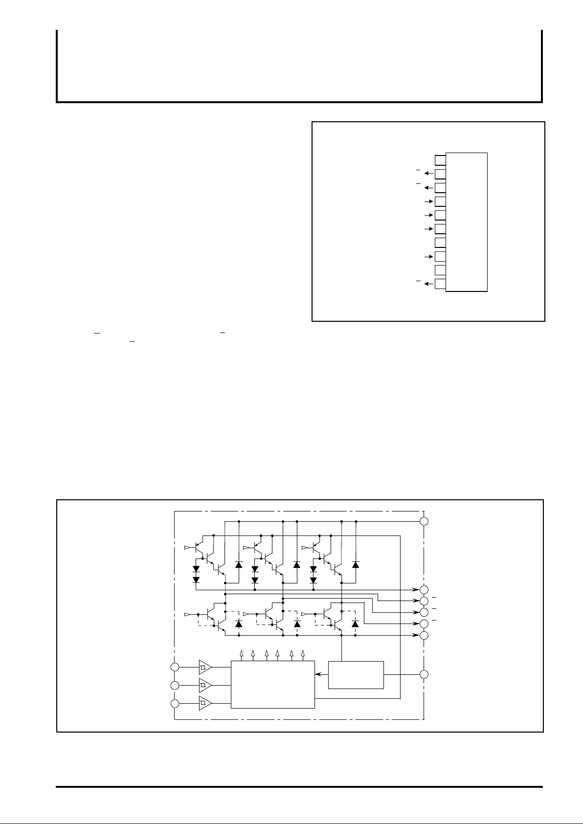
PIN CONFIGURATION (TOP VIEW)
Output 2
Output 3
Input 1
Input 2
Input 3
Power supply 1
Input for output control
Power supply 2 for output
Output 1
GND
V
V
O
O
IN
IN
IN
CC1
V
CC2
O
2
3
1
2
3
R
1
1
2
3
4
M54649L
5
6
7
8
9
10
Outline 10P5
BLOCK DIAGRAM
Input 1 IN1
Input 2 IN2
Input 3 IN3
Control circuit
Constant current
circuit (thermal
shutdown circuit)
VCC2 Power supply 2 for output
VR Input for output control
Output 1O1
O
2 Output 2
O
3 Output 3
GND
CC1
V
MITSUBISHI <CONTROL / DRIVER IC>
DUAL Bi-DIRECTIONAL MOTOR DRIVER
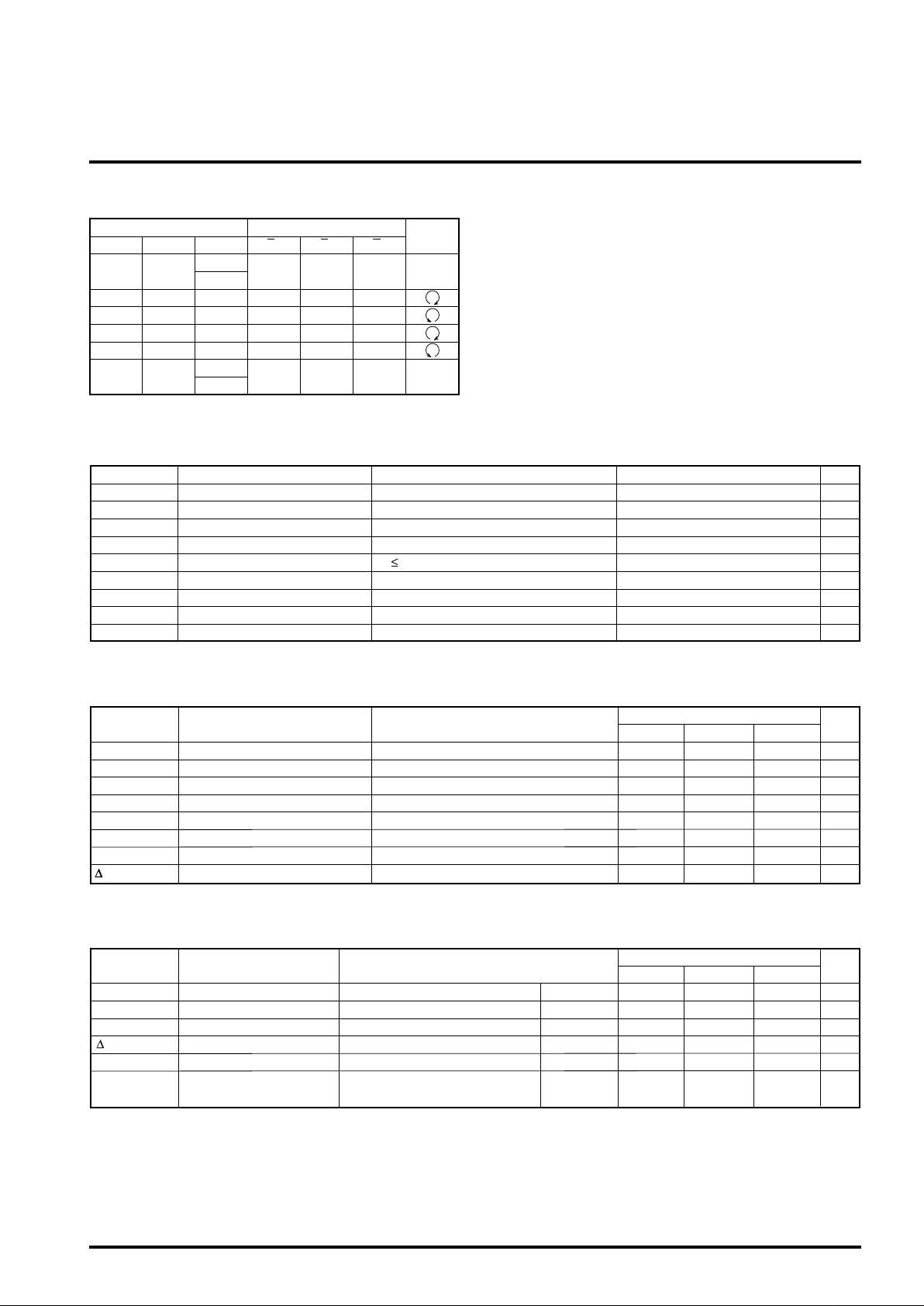
LOGIC TRUTH TABLE
Input
IN1
LL
2 IN3 O1 O2 O3
IN
L
H
H L L H L OPEN
H
L
L
H
L H L H OPEN
H L H OPEN L
H H L OPEN H
H
L
H
Output
Remarks
L L L Brake
L L L Brake
ABSOLUTE MAXIMUM RATINGS (Ta = 25°C, unless otherwise noted)
Symbol Ratings UnitParameter Conditions
VCC(1)
VCC(2)
VI
O
V
IOP
IO
d Power dissipation
P
T
opr Operating temperature
stg Storage temperature
T
Note 1: Pay attention to P
Supply voltage(1)
Supply voltage(2)
V
Input voltage
CC(1) or less
Output voltage
Motor rush current
Continuous output current
op 50ms ; duty of 1/50
t
(Note 1)
Power apply time of 10sec or less
d when the IC operations in the stationary status.
-0.5 – +20.0
-0.5 – +22.0
-0.5 – +7.0
-2.0 – V
CC+2.5
±1.60
±600
2.78
-20 – 75
-55 – 125
M54649L
V
V
V
V
A
mA
W
˚C
˚C
RECOMMENDED OPERATI NG CONDI TIO N (Ta=25°C, unless otherwise noted)
Symbol Conditions
CC(1) Supply voltage(1) 4.0
V
Supply voltage(2)VCC(2)
IO
VIH
Output current
“H”input voltage
VIL “L” input voltage
V
R Control voltage
ON Thermal shutdown temperature
T
ON-OFF Hysteresis temperature width
T
Parameter
ELECTRICAL CHARACTERISTICS (Ta=25°C, unless otherwise noted)
Symbol
O(leak)
I
VOL
VOH
V O
IR
CC1 Supply current
I
Parameter
Output leak current
“L”
output saturation voltage
“H” output saturation voltage
Output offset voltage
8-pin output current
Output OPEN status VO = 0 or 20V
I
OL = 500mA
OH = -500mA
I
O = ±500mA VR = 6.0V
I
O = ±500mA VR = 6.0V
I
IN1,2,3 = 1.0V
V
IO = 0mA Output OPEN
Test conditions Unit
CC1,2 = 20V
V
V
CC1,2 = 12V
V
CC1,2 = 12V
V
CC1,2 = 12V
V
CC1,2 = 12V
CC1,2 = 12V
V
Limits
Min. Typ.
12.0
Max.
18.0
0.0 22.0
±600
3.5 V
0.0 1.0
0.0 18.0
125 150
50
Limits
Min. Typ.
Max.
±100
10.0
-0.5 0.5
0.2 1.5
24.08.0
1.5
CC
Unit
V
V
mA
V
V
V
˚C
˚C
µA
V
V
V
mA
mA
 Loading...