

Page 1

DATA PROJECTOR
MODEL
XD80U
User Manual
* DLP™ (Digital Light Processing) and DLP™ chip are registered trademarks of Texas Instru-ments Incorporated (U.S.A.).
* VGA and XGA are trademarks or registered trademarks of International Business Machines Corporation (U.S.A.).
* S-VGA is a registered trademark of Video Electronics Standards Association.
* Microsoft, Windows, and PowerPoint are registered trademarks of Microsoft Corporation (U.S.A. and other countries).
* Macintosh is a trademark of Apple Computer Inc. (U.S.A.).
Note that even in the absence of explanatory notes, serious attention is paid to the trademarks of the various companies
and to the product trademarks.
IMPORTANT
XD80
Page 2

IMPORTANT SAFETY INFORMATION
CAUTION
RISK OF ELECTRIC SHOCK
CAUTION: TO REDUCE THE RISK OF ELECTRIC SHOCK,
DO NOT REMOVE COVER (OR BACK)
NO USER-SERVICEABLE PARTS INSIDE
REFER SERVICING TO QUALIFIED
The lightning flash with arrowhead symbol, within an equilateral triangle, is intended to alert the
user to the presence of uninsulated “dangerous voltage” within the product’s enclosure that
may be of sufficient magnitude to constitute a risk of electric shock.
The exclamation point within an equilateral triangle is intended to alert the user to the presence
of important operating and maintenance (servicing) instructions in the literature accompanying
the appliance.
WARNING:
TO PREVENT FIRE OR SHOCK HAZARD, DO NOT EXPOSE THIS APPLIANCE TO RAIN OR
MOISTURE.
CAUTION:
TO PREVENT ELECTRIC SHOCK, DO NOT USE THIS (POLARIZED) PLUG WITH AN EXTENSION CORD, RECEPTACLE OR OTHER OUTLET UNLESS THE BLADES CAN BE FULLY INSERTED TO PREVENT BLADE EXPOSURE.
NOTE:
SINCE THIS PROJECTOR IS PLUGGABLE EQUIPMENT, THE SOCKET-OUTLET SHALL BE INSTALLED NEAR THE EQUIPMENT AND SHALL BE EASILY ACCESSIBLE.
DO NOT OPEN
SERVICE PERSONNEL.
WARNING
Use the attached specified power supply cord. If you use
another power-supply cord, it may cause interference with
radio and television reception.
Use the included RGB cable, a commercially available video
cable, an audio cable to which the included ferrite core is
mounted and a separately sold component cable with ferrite core so as to keep interference within the limit of an
FCC Class B Device.
This apparatus must be grounded.
DO NOT LOOK DIRECTLY INTO THE LENS WHEN
THE PROJECTOR IS IN THE POWER ON MODE.
CAUTION
Not for use in a computer room as defined in the Standard
for the Protection of Electronic Computer/Data Processing
Equipment, ANSI/NFPA 75.
The attached power cords are to be used exclusively for
this product. Never use them for other products.
Note:
This symbol mark is for EU
countries only.
This symbol mark is according to the directive
2002/96/EC Article 10 information for users and Annex IV.
Your MITSUBISHI ELECTRIC product is designed and manufactured with high
quality materials and components which can be recycled and reused.
This symbol means that electrical and electronic equipment, at their end-of-life,
should be disposed of separately from your household waste.
Please, dispose of this equipment at your local community waste collection/recycling centre.
In the European Union there are separate collection systems for used electrical
and electronic product.
Please, help us to conserve the environment we live in!
When using the projector in Europe:
COMPLIANCE NOTICE
This Projector complies with the requirements of the EC
Directive 89/336/EEC “EMC Directive” as amended by Directive 92/31/EEC and 93/68/EEC, and 73/23/EEC “Low
Voltage Directive” as amended by Directive 93/68/EEC.
The electro-magnetic susceptibility has been chosen at a
level that gains proper operation in residential areas, on
business and light industrial premises and on small-scale
enterprises, inside as well as outside of the buildings. All
places of operation are characterised by their connection
to the public low voltage power supply system.
WARNING
Use the included RGB cable, a commercially available video
cable, an audio cable to which the included ferrite core is
mounted and a separately sold component cable with ferrite core so as to keep interference within the limit of an
EN55022 Class B Device.
Please follow WARNING instructions.
E-1
Page 3

IMPORTANT SAFETY INFORMATION
Please read all these instructions regarding your projector
and retain them for future reference. Follow all warnings
and instructions marked on the projector.
1. Read instructions
All the safety and operating instructions should be
read before the appliance is operated.
2. Retain instructions
The safety and operating instructions should be retained for future reference.
3. Warnings
All warnings on the appliance and in the operating
instructions should be adhered to.
4. Instructions
All operating instructions must be followed.
5. Cleaning
Unplug this projector from the wall outlet before
cleaning it. Do not use liquid aerosol cleaners. Use a
damp soft cloth for cleaning.
6. Attachments and equipment
Never add any attachments and/or equipment without the approval of the manufacturer as such additions may result in the risk of fire, electric shock or
other personal injury.
7. Water and moisture
Do not use this projector near water or in contact
with water.
8. Accessories
Do not place this projector on an unstable cart, stand,
tripod, bracket or table. Use only with a cart, stand,
tripod bracket, or table recommended by the manufacturer or sold with the projector. Any mounting of
the appliance should follow the manufacturer’s instructions and should use a mounting accessory recommended by the manufacturer.
An appliance and cart combination should be moved
with care. Quick stops, excessive force and uneven
surfaces may cause the appliance and cart combination to overturn.
9. Ventilation
Slots and openings in the cabinet are provided for
ventilation, ensuring reliable operation of the projector and to protect it from overheating. Do not block
these openings or allow them to be blocked by placing the projector on a bed, sofa, rug, or bookcase.
Ensure that there is adequate ventilation and that
the manufacturer’s instructions have been adhered
to.
10. Power sources
This projector should be operated only from the type
of power source indicated on the marking label. If
you are not sure of the type of power, please consult
your appliance dealer or local power company.
11. Power-cord protection
Power-supply cords should be routed so that they
are not likely to be walked on or pinched by items
placed upon or against them. Pay particular attention to cords at plugs, convenience receptacles, and
points where they exit from the appliance. Do not
put the power cord under a carpet.
12. Overloading
Do not overload wall outlets and extension cords as
this can result in a fire or electric shock.
13. Objects and liquids
Never push objects of any kind through openings of
this projector as they may touch dangerous voltage
points or short-out parts that could result in a fire or
electric shock. Never spill liquid of any kind on the
projector.
14. Servicing
Do not attempt to service this projector yourself. Refer all servicing to qualified service personnel.
15. Damage requiring service
Unplug this projector from the wall outlet and refer
servicing to qualified service personnel under the
following conditions:
(a) If the power-supply cord or plug is damaged.
(b) If liquid has been spilled, or objects have fallen
into the projector.
(c) If the projector does not operate normally after
you follow the operating instructions. Adjust only
those controls that are covered by the operating
instructions. An improper adjustment of other
controls may result in damage and may often
require extensive work by a qualified technician
to restore the projector to its normal operation.
(d) If the projector has been exposed to rain or wa-
ter.
(e) If the projector has been dropped or the cabinet
has been damaged.
(f) If the projector exhibits a distinct change in per-
formance - this indicates a need for service.
16. Replacement parts
When replacement parts are required, be sure that
the service technician has used replacement parts
specified by the manufacturer or parts having the
same characteristics as the original part. Unauthorized substitutions may result in fire, electric shock
or other hazards.
17. Safety check
Upon completion of any service or repair to this projector, ask the service technician to perform safety
checks determining that the projector is in a safe
operating condition.
E-2
Page 4

IMPORTANT SAFETY INFORMATION
WARNING:
Unplug immediately if there is something wrong with
your projector.
Do not operate if smoke, strange noise or odor comes
out of your projector. It might cause fire or electric shock.
In this case, unplug immediately and contact your dealer.
Never remove the cabinet.
This projector contains high voltage circuitry. An inadvertent contact may result in an electric shock. Except
as specifically explained in the Owner’s Guide, do not
attempt to service this product yourself. Please contact
your dealer when you want to fix, adjust or inspect the
projector.
Do not modify this equipment.
It can lead to fire or electric shock.
If you break or drop the cabinet.
Do not keep using this equipment if you break or drop it.
Unplug the projector and contact your dealer for inspection. It may lead to fire if you keep using the equipment.
Do not face the projector lens to the sun.
It can lead to fire.
Use correct voltage.
If you use incorrect voltage, it can lead to fire.
Do not place the projector on uneven surface.
Place the projection on a leveled and stable surface only.
Please do not place equipment on unstable surfaces.
Do not look into the lens when it is operating.
It may hurt your eyes. Never let children look into the
lens when it is on.
Do not unplug the projector during operation.
It can lead to lamp breakage, fire, electric shock or other
trouble.
Do not touch Air outlet grille and Bottom plate which
becomes hot.
Do not touch them or put other equipment in front of Air
outlet grille. The heated Air outlet grille and Bottom plate
may cause injury or damage to other equipment. Also,
do not set the projector on the desk which is easily affected by heat.
Do not look into the air outlet grille when projector
is operating.
Heat, dust etc. may blow out of it and hurt your eyes.
Do not block the air inlet and outlet grilles.
If they are blocked, heat may be generated inside the
projector, causing deterioration in the projector quality
and fire.
Place of installation
For safety’s sake, refrain from setting the projector at
any place subjected to high temperature and high humidity. Please maintain an operating temperature, humidity, and altitude as specified below.
• Operating temperature: between +41°F (+5°C) and
+95°F (+35°C)
• Operating humidity: between 30 and 85%
• Never put any heat-producing device under the pro-
jector so that the projector does not overheat.
• Do not attach the projector to a place that is unstable
or subject to vibration.
• Do not install the projector near any equipment that
produces a strong magnetic field. Also refrain from
installing near the projector any cable carrying a large
current.
• Place the projector on a solid, vibration free surface:
otherwise it may fall, causing serious injury to a child
or adult, and serious damage to the product.
• Do not stand the projector: it may fall, causing serious
injury and damage to the projector.
• Slanting the projector more than ±10°(right and left)
or ±15° (front and rear) may cause trouble or explosion of the lamp.
• Do not place the projector near air-conditioning unit
or heater to avoid hot air to the exhaust and ventilation hole of the projector.
COMPLIANCE NOTICE OF FCC
This equipment has been tested and found to comply with the limits for a Class B digital device, pursuant to Part
15 of the FCC Rules. These limits are designed to provide reasonable protection against harmful interference in
a residential installation. This equipment generates, uses and can radiate radio frequency energy and, if not
installed and used in accordance with the instructions, may cause harmful interference to radio communications.
However, there is no guarantee that interference will not occur in a particular installation. If this equipment does
cause harmful interference to radio or television reception, which can be determined by turning the equipment
off and on, the user is encouraged to try to correct the interference by one or more of the following measures:
• Reorient or relocate the receiving antenna.
• Increase the separation between the equipment and receiver.
• Connect the equipment into an outlet on a circuit different from that to which the receiver is connected.
• Consult the dealer or an experienced Radio / TV technician for help.
Changes or modifications not expressly approved by Mitsubishi could void the user’s authority to operate this
equipment.
COMPLIANCE NOTICE OF INDUSTRY CANADA
This Class B digital apparatus complies with Canadian ICES-003.
E-3
Page 5

Major Features
䡵 Evolution of the Best Seller Mobile Projector
The ease of use of this take anywhere, anytime, mobile projector has been improved and despite its small size and light
weight, it produces a high brightness of 1300 lm and a high contrast ratio of 2000:1. The newly developed Iris Lens Cover and
Auto Keystone permit speedy setup and projection, and after the presentation is finished, just switch off the power of the
projector and the Instant Shut Down function allows it to soon be moved to another location.
䡵 DCM “Dual Color Mode”
This next-generation small sized projector contains a “dual color mode” function, the world’s first for a small sized projector.
The use of two color wheels permits optimum color combination to suit the scene, thereby greatly improving color reproduction.
䡵 Sharp, clear picture
The DLP™ display system affords RGB color fidelity and inconspicuous gaps between the individual dots, thereby permitting
the display of small characters and diagrams with distinct clarity.
䡵 High contrast ration of 2000:1
Use of a new generation of DLP™ chip devices has given birth to an amazing 2000:1 high contrast ratio.
By widening the difference of brightness between black and white, you can see a degree of sharpness that is greater than just
the brightness based on specifications.
䡵 Powerful functions for presentations
A wide variety of easy-to-set functions have been built into the projector, from a digital keystone correction function (used
E-4
Page 6

Table of Contents
IMPORTANT SAFETY INFORMATION ................................................................................... E-2
Major Features ....................................................................................................................... E-4
Table of Contents ................................................................................................................... E-5
Checking the Supplied Accessories .................................................................................... E-7
Names of the Main Unit Parts ............................................................................................... E-8
Names of the Remote Control Parts................................................................................... E-10
Preparing the Remote Control ............................................................................................ E-11
Button Battery Replacement ..................................................................................... E-11
Remote Control Range ............................................................................................. E-11
The Procedure Up to Projecting to the Screen ................................................................. E-12
Placement Guide .................................................................................................................. E-13
Screen Size and Projection Distance ........................................................................ E-13
Connecting Personal Computers and Video Equipment .................................................. E-14
Connections with Personal Computer ....................................................................... E-14
Connect the projector’s RGB connector using the included RGB signal cable. .. E-14
To Output the External Output Signal of a Notebook Computer ......................... E-15
Connections with Composite Signals ........................................................................ E-16
Video Equipment with VIDEO Connectors .......................................................... E-16
Video Equipment with S-VIDEO Connectors ...................................................... E-16
Connections with Component Signals ....................................................................... E-17
When the Video Equipment Has a YCbCr Connector or YPbPr Connector ........ E-17
Connections with the AUDIO Jack ............................................................................ E-18
Power Cable Connections and Switching the Power On/Off ........................................... E-19
Operating ................................................................................................................... E-19
Finishing .................................................................................................................... E-21
Adjustment of the Projection Screen ................................................................................. E-22
Adjustment of the Projection Screen ......................................................................... E-22
Making Adjustments with the Adjusters .............................................................. E-23
General Operation ................................................................................................................ E-24
Input Selection .......................................................................................................... E-24
Automatic Adjustment ............................................................................................... E-24
Selection of Aspect Ratio .......................................................................................... E-25
Freezing a Moving Picture ......................................................................................... E-26
Cancelling Video and Audio Temporarily ................................................................... E-26
Lamp Mode ............................................................................................................... E-26
Selection of the Color Mode (DCM) .......................................................................... E-26
Keystone Manual Adjustment .................................................................................... E-27
Adjustment of the Volume .......................................................................................... E-27
Enlargement of the Image and Video Movement ...................................................... E-28
Using the Presentation Timer .................................................................................... E-29
Protecting the Projector with the Security Lock ......................................................... E-30
Using the Quick Menu ............................................................................................... E-32
Menu Operation Method ...................................................................................................... E-33
Performing Menu Operations .................................................................................... E-35
List of Item Names Offering Input Selection and Adjustments/Settings .................... E-38
Image ..................................................................................................................................... E-40
Brightness / Contrast / Color / Tint / Sharpness ........................................................ E-40
Picture Adj. / Fine Picture / H Position / V Position .................................................... E-40
Reset ......................................................................................................................... E-41
Color ...................................................................................................................................... E-42
Dual Color Mode ....................................................................................................... E-42
Gamma ..................................................................................................................... E-42
Color Temp. ............................................................................................................... E-43
White ......................................................................................................................... E-43
Color Space .............................................................................................................. E-43
White Balance ........................................................................................................... E-44
E-5
Page 7

Table of Contents
View ....................................................................................................................................... E-45
Aspect ....................................................................................................................... E-45
Filter .......................................................................................................................... E-45
Vertical Flip / Horizontal Flip ...................................................................................... E-46
Keystone.................................................................................................................... E-46
Auto Keystone ........................................................................................................... E-46
Setup ..................................................................................................................................... E-47
Auto Source............................................................................................................... E-47
Auto Power Off .......................................................................................................... E-47
Menu Position............................................................................................................ E-48
Lamp Mode ............................................................................................................... E-48
Input Format .............................................................................................................. E-49
Presentation Timer .................................................................................................... E-49
Volume ...................................................................................................................... E-49
Option ................................................................................................................................... E-50
Language .................................................................................................................. E-50
On Screen ................................................................................................................. E-50
Background ............................................................................................................... E-50
Startup Screen .......................................................................................................... E-51
Security Lock ............................................................................................................. E-51
Info......................................................................................................................................... E-52
Status ........................................................................................................................ E-52
Factory Default .......................................................................................................... E-52
Lamp Timer Reset ..................................................................................................... E-52
Resolution / Frequency ............................................................................................. E-53
Lamp Timer ............................................................................................................... E-53
When an Indicator is Lit or Blinking ................................................................................... E-54
Troubleshooting ................................................................................................................... E-55
Cleaning ................................................................................................................................ E-56
Replacing the Lamp Cartridge ............................................................................................ E-57
Specifications ....................................................................................................................... E-60
Table of Supported Frequency ........................................................................................... E-61
Cabinet Dimensions ............................................................................................................ E-62
Declaration of Conformity
Model Number : XD80U
Trade Name : MITSUBISHI ELECTRIC
Responsible party : Mitsubishi Digital Electronics America, Inc.
9351 Jeronimo Road, Irvine, CA 92618 U.S.A.
Telephone number : +1-(949) 465-6000
This device complies with Part 15 of the FCC Rules. Operation is subject to the following two conditions:
(1) this device may not cause harmful interference, and
(2) this device must accept any interference received, including interference that may cause undesired operation.
E-6
Page 8
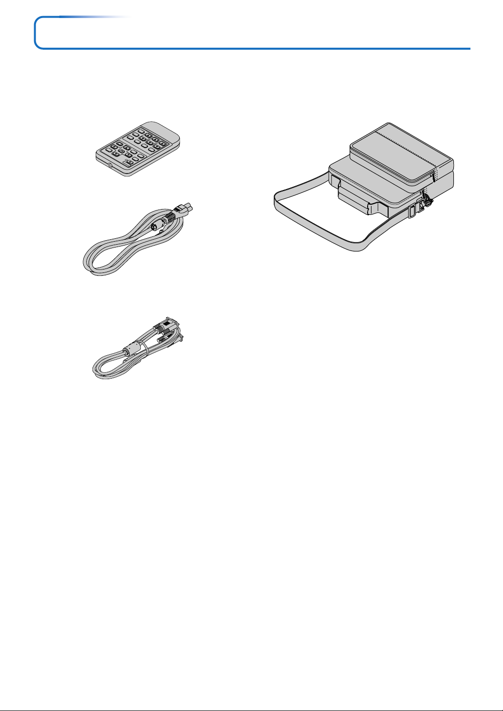
Checking the Supplied Accessories
Remove the main unit and the accessories from the box and check that the following items are included.
Wireless remote control unit
(includes one button battery) [1]
This controls the projector. Please remove the transportation
insulation sheet at time of purchase. (See Page E-11.)
TIMER
ASPECT
ZOOM
AUTO
Q
QUICK
MENU
ENTER
KSTN
LAMP MODE
VOL
MUTE
1234
FREEZE
CANCEL
VIDEO
RGB
DBY
TAN
S
Power cable (1.8 m / 5.9 feet) [1]
Each power cable supplies power to the unit. See Page E-19
about connections.
US: No. 246C484-10
EU: No. 246C484-20
UK: No. 246C484-30
RGB signal cable
(Mini D-sub 15-pin, 2 m / 6.6 feet) [1]
This is used in making connections with a personal computer.
See Page E-14 about connections.
No. 246C553-10
Carrying case (for projector and accessories) [1]
This is a case designed for storing the projector and its accessories.
Use this carrying case when storing or moving the projector.
E-7
Page 9
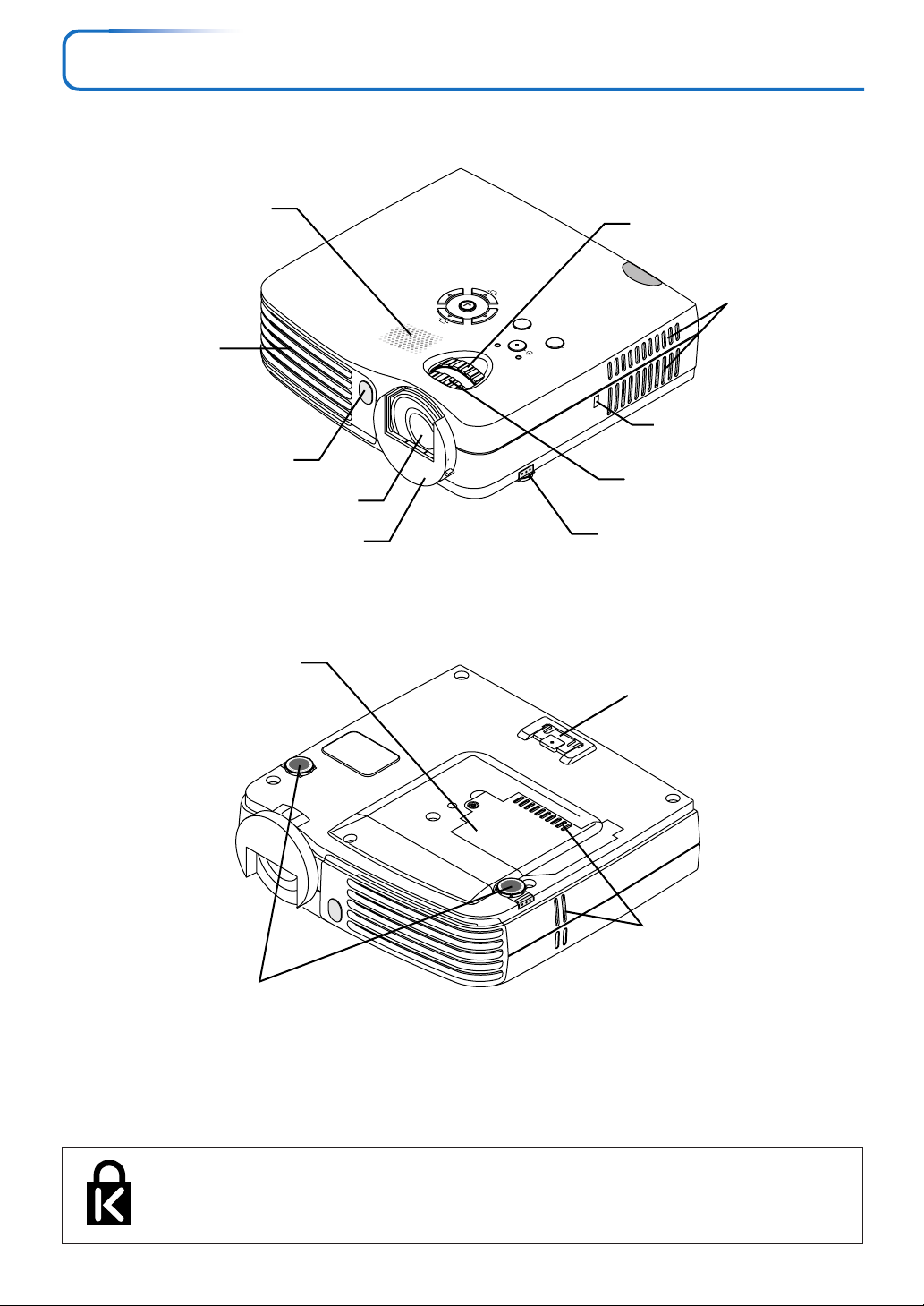
Names of the Main Unit Parts
Exhaust vents
Remote control
sensor [E-11]
Lamp cover [E-58]
Speaker
Lens
Lens cover
Zoom ring [E-22]
AUTO
E
C
R
U
O
S
MODE
DUAL COLOR
DBY
STAN
MENU
STATUS
Ventilation slots
Built-in security slot
CL
O
Z
E
(See description below.)
Focus ring [E-23]
Adjuster button [E-23]
(Also on opposite side)
Rear adjuster [E-23]
Ventilation slots
Front adjusters [E-23]
Built-in Security Slot
This security slot supports the MicroSaver Security System manufactured by
Kensington Microware Inc.
E-8
Page 10
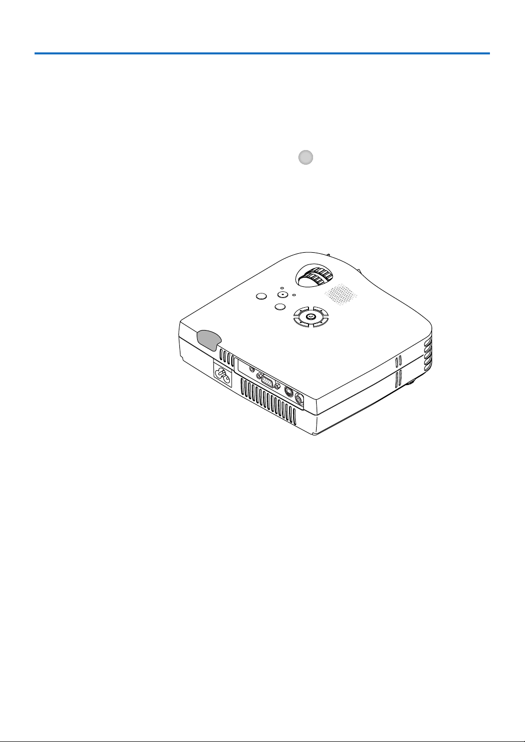
Names of the Main Unit Parts
AUDIO
RGB
S-VIDEO
VIDEO
E-9
Page 11
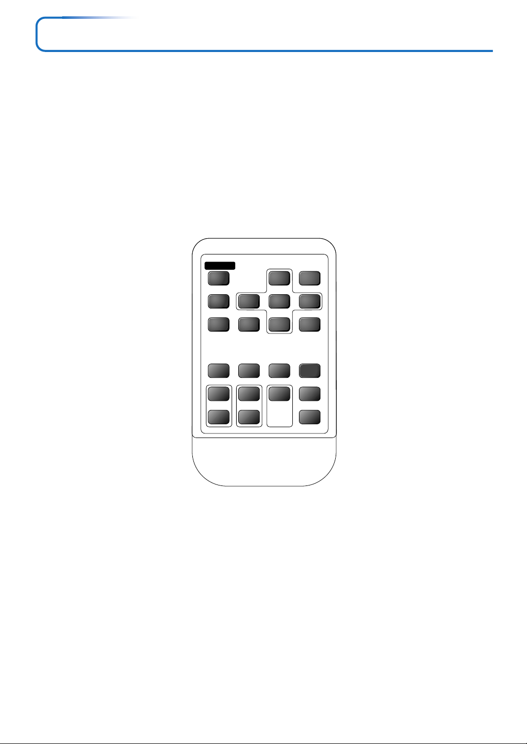
Names of the Remote Control Parts
MENU
LAMP MODE AUTO
MUTE
ENTER
RGB
CANCEL QUICK
VIDEO
FREEZE
VOL KSTN ZOOM
ASPECT
TIMER
E-10
Page 12
CR2025
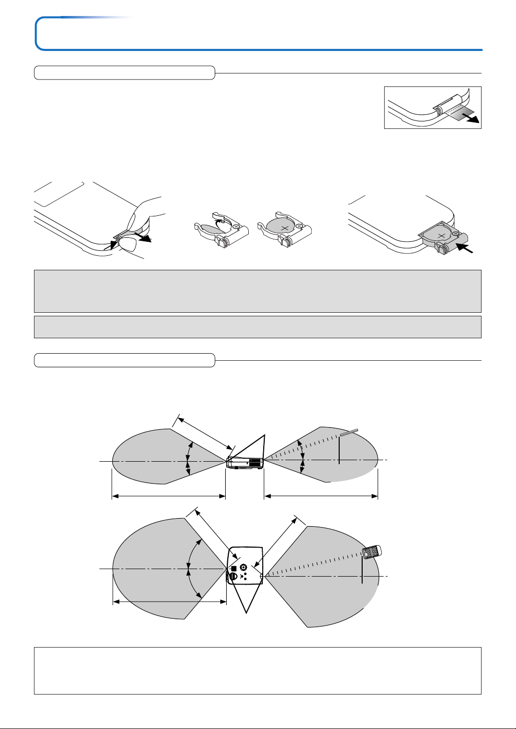
Preparing the Remote Control
Button Battery Replacement
Using the remote control for the first time
The battery compartment is fitted with a transportation insulation sheet at the time of shipping. Pull
out the sheet and remove it. The remote control is now ready for use.
Replacement Method
(A) With the knob pressed to
1
the right side, (B) draw out the
battery case.
Remove the old battery and in-
2
stall a new button battery with (+)
side facing upward in the battery
holder.
Insert the battery holder into the re-
3
mote control and push in until the
battery holder closes with a “click”
sound.
CR2025
(A)
CAUTION
Danger of explosion if battery is incorrectly replaced.
Replace only with the same or equivalent type (CR2025) recommended by the manufacturer.
Dispose of used batteries according to your local regulations.
CAUTION
DISPOSE OF USED BATTERIES ACCORDING TO THE INSTRUCTIONS.
(B)
Purchase a CR2025 type battery for replacement.
CR2025
Remote Control Range
Point the infrared transmitter of the remote control toward the remote control sensor located at the front or rear of the main unit
and operate.
Reception of the remote control signal should generally be possible within the range illustrated below.
4m/13.1 feet
30°
20°
7m/23.0 feet
3m/9.8 feet
Remote control
sensor
Side View
30°
20°
6m/19.7 feet
Remote control infrared
transmitter
50°
50°
7m/23.0 feet
Remote control sensor
Top View
Note
* Exposure of the main unit’s remote control sensor or the remote control infrared transmitter to bright light or the obstruction of the signal
by an obstacle located in the pathway may prevent operation.
* The remote control will not function when the battery is exhausted.
4m/13.1 feet
Remote control infrared transmitter
E-11
Page 13

The Procedure Up to Projecting to the Screen
Perform setup adjustments in the following order.
1 Position the projector
Determine the locations to set up the screen and the projector.
See “Placement Guide” on Page E-13.
2 Connect the video equipment and personal computer
Connect your equipment to the projector.
When making connections with the personal computer’s RGB connector, see “Connections with
Personal Computer” on Page E-14.
When making connections with the video equipment’s video connector or an S-video connector,
see “Connections with Composite Signals” on Page E-16.
When making connections with the video equipment’s YCbCr connector or YPbPr connector,
see “Connections with Component Signals” on Page E-17.
When playing the audio through the built-in speaker of the projector, see “Connections with the
AUDIO Jack” on Page E-18.
3 Connect the power cable and open the lens cover.
See “Operating” on Page E-19.
See “Finishing” on Page E-21.
4 When selecting the language of menu displays, etc.
(Only when the power is first switched on following purchase)
See “When [Menu Language Select] is Displayed Upon Switching On the Power” on Page E-20.
5 Switching on the power of the personal computer and video equipment
6 Properly adjust the projection image to the screen
See “Adjustment of the Projection Screen” on Page E-22.
7 Selecting input equipment
See “Input Selection” on Page E-24.
8 Adjust the screen or video image
Adjust the image to the optimum condition as required.
See the Table of Contents for the adjustment items.
About DLP projectors
Though careful attention is paid to providing optimum quality, please note that with DLP type projectors, in rare cases there may
be black spots or bright spots among the picture elements.
Note:
* Please purchase a screen.
* A component cable (order code: 246C558-10), which is available separately, is required to connect a DVD player or other equipment with
YCbCr connectors.
* A component cable (order code: 246C558-10), which is available separately, is required to connect high definition (HD) video equipment
or other equipment with YPbPr connectors.
E-12
Page 14
Placement Guide
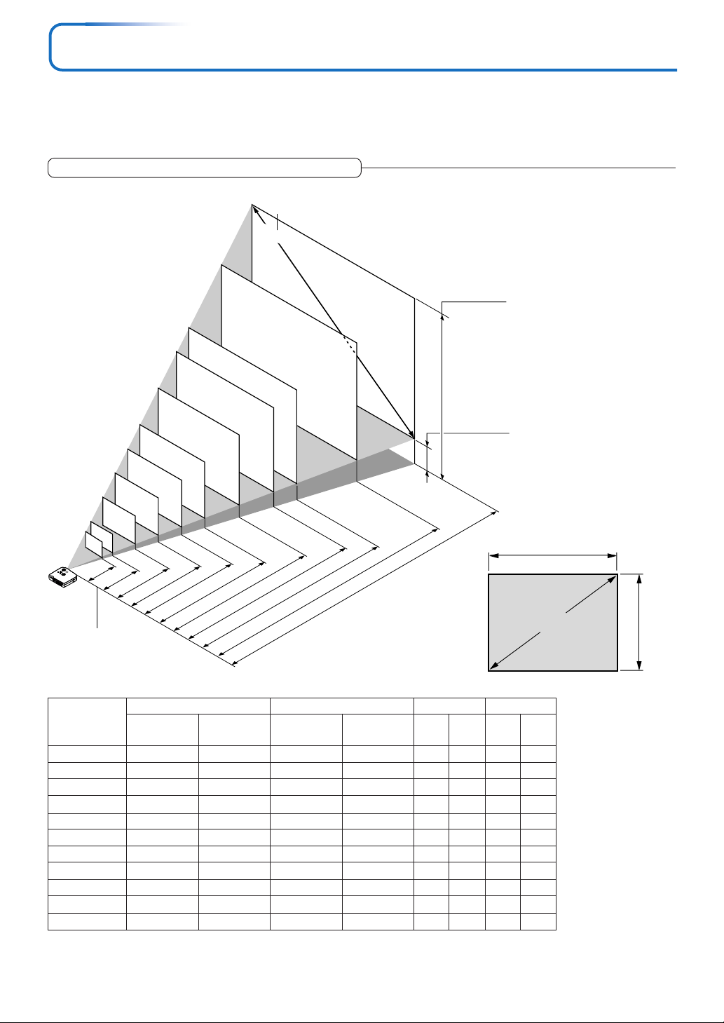
• Use this information as a guide to find out about the screen size when the projector is placed at a certain location, or
to find out the approximate size of a screen that will be required.
• The projection distance over which focussing is adjustable is 1.20 m (3.9 feet) to 14.17 m (46.50 feet). The projector
should be placed within this range.
Screen Size and Projection Distance
Screen Size Designation (Inches)
300"
Height from center of
250"
200"
180"
lens to top edge of
the projection
150"
Height from center of
lens to bottom edge
of the projection
120"
100"
80"
60"
40"
26"
1.20 (3.94)
A
U
D
I
O
R
G
B
S
V
I
D
E
O
V
1.54– 1.85
I
D
E
O
2.33– 2.80
(5.05– 6.07)
(7.64– 9.19)
3.12– 3.75 (10.24–12.30)
4.70– 5.64 (15.42–18.50)
3.91– 4.70 (12.83–15.42)
5.89– 7.07 (19.32– 23.20)
7.07–8.49 (23.20 –27.84)
7.86– 9.44 (25.79– 30.95)
9.84–11.81 (32.28 –38.73)
h1
h2
11.81–14.17 (38.76– 46.50)
Unit: m (feet)
Width
Screen size (Diagonal)
Lens surface of
the main unit
Screen Size
Designation (Inches)
26"
40"
60"
80"
100"
120"
150"
180"
200"
250"
300"
Screen Size Width x Height Projection Distance Height h1 Height h2
(m) (feet)
(m) (feet) (m) (feet) (m) (feet)
Wide – Tele Wide – Tele
0.53 ⳯ 0.40
0.81 ⳯ 0.61
1.22 ⳯ 0.91
1.63 ⳯ 1.22
2.03 ⳯ 1.52
2.44 ⳯ 1.83
3.05 ⳯ 2.29
3.66 ⳯ 2.74
4.06 ⳯ 3.05
5.08 ⳯ 3.81
6.10 ⳯ 4.57
1.73 ⳯ 1.30
2.67 ⳯ 2.00
4.00 ⳯ 3.00
5.33 ⳯ 4.00
6.67 ⳯ 5.00
8.00 ⳯ 6.00
10.00 ⳯ 7.50
12.00 ⳯ 9.00
13.33 ⳯10.00
16.67 ⳯12.50
20.00 ⳯15.00
— – 1.20
1.54 – 1.85
2.33 – 2.80
3.12 – 3.75
3.91 – 4.70
4.70 – 5.64
5.89 – 7.07
7.07 – 8.49
7.86 – 9.44
9.84 –11.81
11.81 –14.17
— – 3.94
5.04 – 6.08
7.64 – 9.19
10.23 –12.30
12.82 –15.41
15.42 –18.52
19.31 –23.18
23.20 –27.84
25.79 –30.95
32.28 –38.73
38.76 –46.50
0.47
0.71
1.07
1.43
1.78
2.14
2.68
3.21
3.57
4.46
5.35
1.52
2.34
3.51
4.68
5.85
7.02
8.78
10.53
11.70
14.63
17.55
0.07
0.10
0.16
0.21
0.26
0.31
0.39
0.47
0.52
0.65
0.78
0.22
0.34
0.51
0.68
0.85
1.02
1.28
1.53
1.70
2.13
2.55
* There is a tolerance of ±5% due to design values.
* This table uses the lens apex and lens center as references and requires that the projector be in a
horizontal condition (with front and rear adjusters fully withdrawn).
Height
E-13
Page 15
Connecting Personal Computers and Video Equipment
Connecting this unit with a personal computer permits presentation data to be projected as a large screen display at
conferences, lectures, and on other occasions. Furthermore, connecting this unit to a DVD player or other video equipment source in combination with an audio/video amplifier and speaker system will allow you to enjoy convincing home
theater.
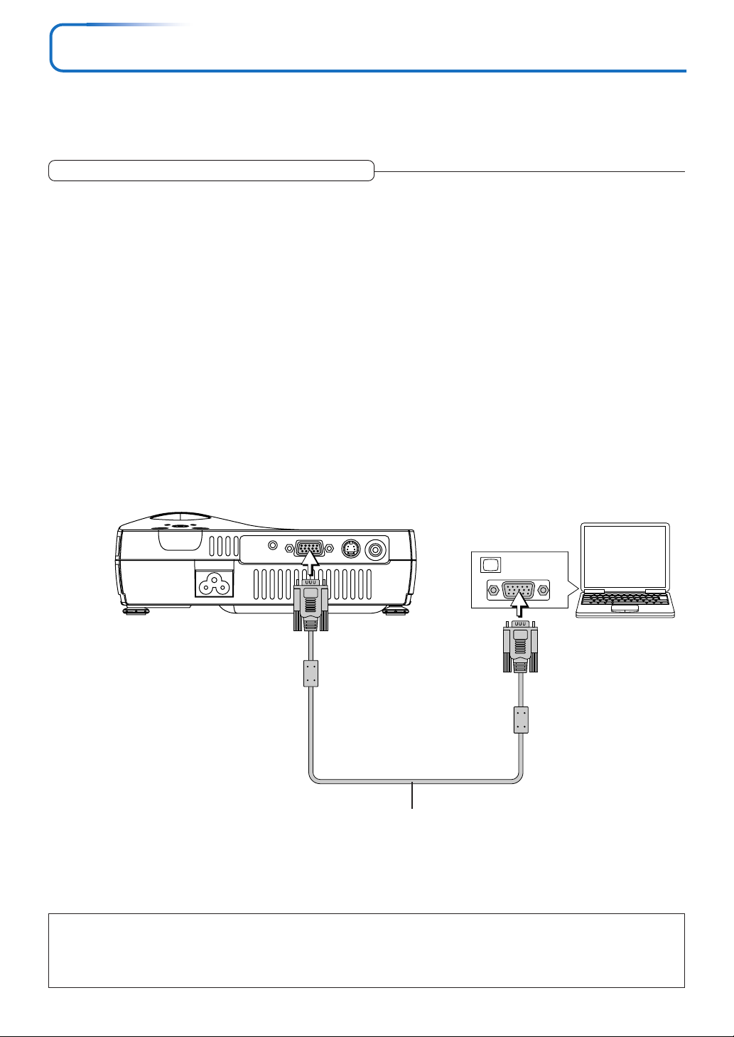
Connections with Personal Computer
Please check the following before making connections with the personal computer.
• A suitable resolution for this projector is 1024 ⳯ 768 dots (XGA). The maximum displayable resolution is 1280 ⳯ 1024 dots (S-
XGA).
Make changes to a displayable resolution at the personal computer side. Please check with “Table of Supported Frequency” on
Page E-61.
• The setting method for the personal computer will differ depending on the specific model. Please read the personal computer
instruction manual or the on-line help information, or contact the manufacturer of your personal computer.
Connect the projector’s RGB connector using the included RGB signal cable.
• When making connections with the RGB connector of the projector, please make the connection via the supplied RGB signal
cable.
• The projector has been set to “Auto” at the factory; however, if it does not project, please change the input setting to “RGB”
using the menu sequence of [Setup] → [Input Format] → [RGB].
See “Input Format” on Page E-49.
MONITOR OUT
Personal
computer
RGB signal cable (Supplied item)
Note:
* Before making connections, check the power of the projector and the equipment to be connected is switched off.
* When projection will be with a notebook computer connected, knowledge will be required for the cable connection and notebook computer
startup procedure as well as the operation that follows startup. Please consult the instruction manual of your notebook computer or the online help.
E-14
Page 16

Connecting Personal Computers and Video Equipment
To Output the External Output Signal of a Notebook Computer
When projection will be with a notebook computer connected, knowledge will be required for the cable connection and notebook
computer startup procedure as well as the operation that follows notebook startup. Please consult the instruction manual of your
notebook computer or the on-line help while performing the following procedure.
Check whether a signal is being sent from the notebook computer to the projector.
1
An indication appearing on the liquid crystal display of the notebook computer does not necessarily mean that an external
output signal is being output.
REFERENCE: When “Resolution” or “Frequency” is not displayed under “Info.” on the menu of the projector, this means that
the external output signal is not being output from the personal computer. See “Resolution/Frequency” on Page E-53.
Should a sign not be output from the notebook computer, please try the operation described below.
2
For an IBM PC/AT compatible computer, press the [Fn] key plus any one of the [F1] to [F10] keys. (See the table below.)
Manufacturer Model Key
DELL All computers Fn + F8
EPSON All computers Fn + F8
FUJITSU All computers Fn + F10
iiyama All computers Fn + F3
IBM All computers Fn + F7
NEC All computers Fn + F3
Panasonic All computers Fn + F3
SHARP All computers Fn + F5
SONY All computers Fn + F7
SOTEC All computers Fn + F3–F5
TOSHIBA All computers Fn + F5
Victor All computers Fn + F10
Note: Table information is current to December 2003.
Note:
When the liquid crystal display of the notebook computer and the projector are displayed at the same time, the projected image might not be
correct even though the liquid crystal display shows a correct indication. Should this occur, stop the simultaneous display of the notebook
computer and try the mode with external output only. Try an operation such as that described in aforementioned Step 2 and try closing the
liquid crystal panel which might result in external output only.
E-15
Page 17

Connecting Personal Computers and Video Equipment
Connections with Composite Signals
Video Equipment with VIDEO Connectors
• Connect to the projector’s VIDEO connector using a commercially available video cable. Please attach the supplied ferrite core
to the video cable as described below.
• The input setting of the VIDEO connector has been set to “Auto” at the factory; however, if the projector does not project, please
change the input setting to “Your Country’s Television Broadcast System” using the menu sequence of [Setup] → [Input Format]
→ [Video].
See “Input Format” on Page E-49.
Video Equipment with S-VIDEO Connectors
• Connect to the projector’s S-VIDEO connector using a commercially available S-Video cable.
• The input setting of the S-VIDEO connector has been set to “Auto” at the factory; however, if the projector does not project,
please change the input setting to “Your Country’s Television Broadcast System” using the menu sequence of [Setup] → [Input
format] → [S-Video].
See “Input Format” on Page E-49.
Video deck, DVD player, document
camera, etc.
Ferrite core (Supplied item)
(Mount to projector side of cable)
Video cable (RCA pin plug)
(Not supplied)
S-Video cable (Mini DIN 4-pin plug)
(Not supplied)
Mounting the Ferrite Core
Open the ferrite core, loop the cable through it, then close.
VIDEO
S-VIDEO
Ferrite core
Cable
E-16
Page 18
Connecting Personal Computers and Video Equipment
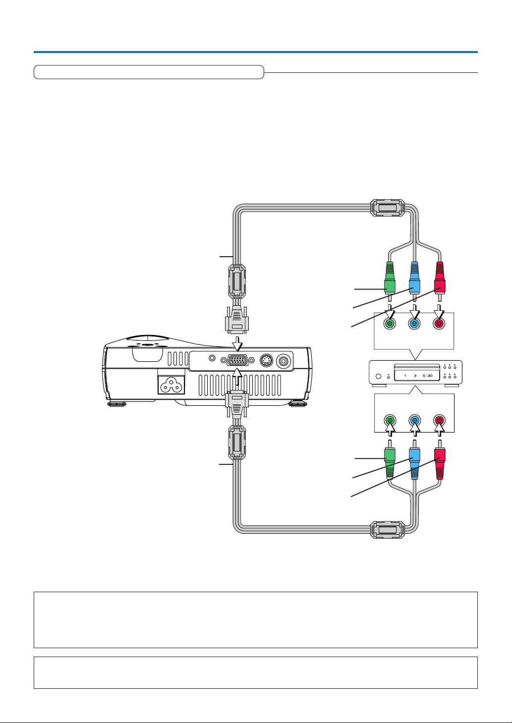
Connections with Component Signals
When the Video Equipment Has a YCbCr Connector or YPbPr Connector
• The projector has been set to “Auto” at the factory; however, if it does not project, please change the input setting to “Component” using the menu sequence of [Setup] → [Input Format] → [RGB].
See “Input Format” on Page E-49.
• When projecting the YCbCr signal or YPbPr signal, if the color of the overall image strongly leans toward being greenish or
another color, change the setting under the menu of [Color] → [Color Space].
See “Color Space” on Page E-43.
Component cable (Available as an option)
(Mini D-sub 15-pin to RCA⳯3)
(Order code: 246C558-10)
Green
Blue
Red
COMPONENT
COMPONENT
Component cable (Available as an option)
(Mini D-sub 15-pin to RCA⳯3)
(Order code: 246C558-10)
Projecting component signals
Please note that when inputting 480i or 576i signals using a separately sold component cable and viewing video images, depending on the
connected device and the video source being projected, the picture may be disturbed or may not be projected properly.
In such cases, it is possible to achieve a picture with no disturbance that is projected properly by either switching to 480p signals or
connecting using an S-Video cable instead.
Green
Blue
Red
CrCbY
PrPbY
Note
In some rare cases, the picture may not be displayed, depending on the connected device.
When the input format has been switched, you may be required to reconnect the input signal.
E-17
Page 19
Connecting Personal Computers and Video Equipment
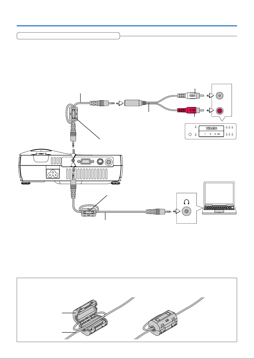
Connections with the AUDIO Jack
* Connect to the projector’s AUDIO jack using a commercially available audio cable. If the other device has an RCA phono type
audio jack, connect via a commercially available audio converter cable. Please attach the supplied ferrite core to the audio
cable as described below.
* The built-in speaker of the projector provides monaural audio. To enjoy convincing audio reproduction, please connect the
audio output of the video equipment to your audio system.
* The built-in speaker outputs the audio of the equipment connected to the AUDIO jack.
Audio cable (Mini plug)
(Not supplied)
Ferrite core (Supplied item)
(Mount to projector side of cable)
Audio cable (Mini plug)
(Not supplied)
Audio conversion cable
(Mini-jack/ RCA pin plug)
(Not supplied)
Ferrite core (Supplied item)
(Mount to projector side of cable)
White
Red
AUDIO OUT
L
R
Mounting the Ferrite Core
Open the ferrite core, loop the cable through it, then close.
Ferrite core
Cable
E-18
Page 20
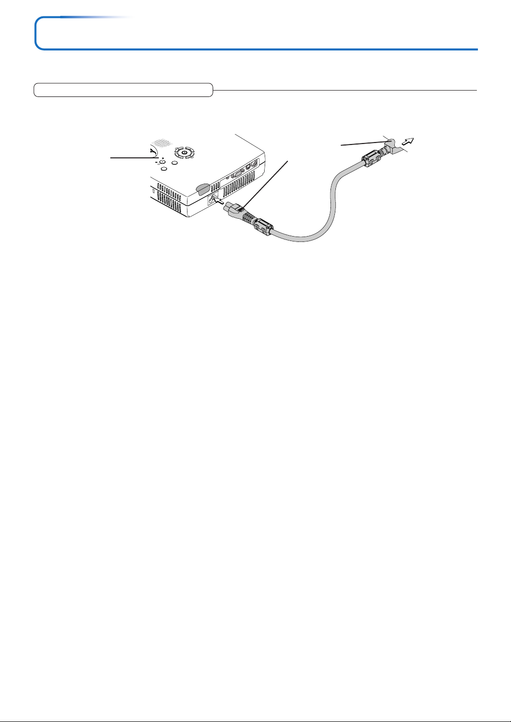
Power Cable Connections and Switching the Power On/Off
There is an order in which the power cable is connected and the power is switched on/off.
Operating
AUTO
E
C
R
U
Y
O
B
S
D
N
A
T
S
R
O
L
STATUS
E
O
D
C
O
L
A
M
U
D
Switch on the projector power
3
MENU
S-VIDEO
RGB
AUDIO
Press the STANDBY button.
The first time the power is switched on after purchase, [Menu
Language Select] will be displayed. See Page E-20 for information about language selection.
• When the power is turned on, the STANDBY indicator starts blinking green, then stops blinking after about 60 seconds. If the STATUS
indicator lights green at this time, the lamp mode is set to 7451(“Lowr)169(”.S)]TJT*-0.0001 Tc-0.0034 Tw[(See E-6 •)-6.2and8 4( f2)8.7(or istruectiosd on selectng.S)]TJ-1.065 -1.2 TD01 Tc-0.4708 Tw[(•)-715 If the po97.9(w)17(erdoes not coime on,sSee,)372(“(When the ST)174.4(A)127(TU Iindicatoris-)]TJ1.065 -1.92 TD0.0001 Tc-0.101 Tw[Lit torg)-90.(B(linkin)16.1”)418.1d on PuageE-54(.)]TJETEmbeddedDocument /MC50 BDCbq0.491 i 354(60935805795824.21-55652 reW nS1 D01Gn0.8 w40 M /G32 gs4)306836 3667915 m464873275.49131602436 70.41131602436 3667915cl360237923707833 l360237925613793367.84725537175.370231725537175c46487lc496.675.-292.493917.302 368.702 49813793368.702cs430781533368.702l4085.653368.70241092.96 -292.4941092.96 30(6487cs4397.324 3390371ls4397.324 339682843978083 340.7124190.404 340.712cs4)223571 340.535l4293.541 340.535429383 34085429383 317.582cs4ST(ANDB3)Tj42.5072 0 042.6636853697 37026708 Tm(VIDEO3)Tj34.6001-0.1075 TD[(CANCEL)-68737.9QUICK-
VIDEO
Firmly plug in all
the way.
To wall outlet
E-19
Page 21

When [Menu Language Select] is Displayed Upon Switching On the Power
The first time the power is switched on after purchase, [Menu Language Select] will be displayed. Follow the procedure described below and select the display language of the projector.
If the image is blurred, turn the focus ring counterclockwise or clockwise to focus it. See Page E-22.
Press the SELECT (왖왔) buttons of the Remote con-
1
trol and align the deep blue cursor with [English].
Cursor
STANDBY
RGB
CANCEL QUICK
VIDEO
FREEZE
1234
VOL KSTN ZOOM
Press the ENTER button to set.
2
MUTE
MENU
ENTER
Q
LAMP MODE AUTO
ASPECT
TIMER
This will set the language and [Menu Language Select] will close.
This completes the selection of the display language.
Caution:
[Menu Language Select] will not appear the next time the power is switched on.
Should a change of language become necessary, see “Language” on Page E-50.
E-20
Page 22

Power Cable Connections and Switching the Power On/Off
Power Off
OK
?
Finishing
1
Switch off the power of the connected equipment
2
Switch off the power of the projector
Press the STANDBY button.
The [Power Off] display appears.
When the level gauge reaches maximum, the projection screen
will go off (in about 5 seconds) and the projector will enter the
power-off operation.
Note:
* The operation can be cancelled by pressing a button other than the
STANDBY button.
* One more press of the STANDBY button will switch off the power.
The STANDBY indicator changes to blinking amber and lights a
steady amber after about 90 seconds (when the unit enters the
standby mode).
STANDBY
ENTER
RGB
CANCEL QUICK
VIDEO
FREEZE
LAMP MODE AUTO
MUTE
1234
MENU
Q
S
Blinking amber
(Approximately 90
seconds)
Lit amber
Standby mode
E-21
Page 23

E-22
Page 24

Adjustment of the Projection Screen
E-23
Page 25

General Operation
This section describes the use of direct operation with the main unit or remote control buttons.
For information about operation using the menu, see “Menu Operation Method” on Page E-33 and the various items on
Pages E-40 to E-53.
Input Selection
STANDBY
ENTER
RGB
CANCEL QUICK
VIDEO
FREEZE
LAMP MODE AUTO
MUTE
1234
VOL KSTN ZOOM
MENU
Q
ASPECT
TIMER
E-24
Page 26

General Operation
Selection of Aspect Ratio
This function selects horizontal and vertical picture proportions of the input
signal.
Press the ASPECT button while viewing the projected image and select the
aspect ratio.
Personal Computer Signal
Each press of the ASPECT button advances the selection one step in the sequence of Auto → Direct → Real, and then repeats.
Auto ............ Automatically enlarges or reduces the image to project a full screen in a ratio
of 4:3
Direct .......... Maintains the aspect ratio and projects a picture of the maximum displayable
size
Real ............ Projects the input signal without pixel conversion.
STANDBY
ENTER
RGB
CANCEL QUICK
VIDEO
FREEZE
LAMP MODE AUTO
MUTE
1234
VOL KSTN ZOOM
MENU
Q
ASPECT
TIMER
Note:
When selection has been made for the “Real” setting of the personal computer signal (i.e., when the input signal and the projector display
resolution are high) and the “Zoom” setting of the video signal, pressing the SELECT (
왖왔왗왘
) buttons on the remote control will permit
movement of the display position. Note that there will not be any movement when the menu or the quick menu is displayed.
E-25
Page 27

General Operation
Freezing a Moving Picture
This function is used to stop and view a moving picture. Note that the input
image continues to advance even though the picture there is a still picture
condition.
A press of the FREEZE button changes the screen to a still picture. A
further press returns the screen to a moving picture.
Cancelling Video and Audio Temporarily
This function is used to cancel the video and audio at the same time.
A press of the MUTE button will blank the picture and the sound, and
the screen will take on the background color that has been set.
Another press will cause a return to the original conditions.
Lamp Mode
Use this if the picture is projected on a small screen and the picture
is too bright or when projecting images in dark rooms.
Pressing the LAMP MODE button will set the lamp mode.
Low (STATUS indicator is lit green)
The lamp’s brightness is reduced to approximately 80%, extending the
lamp’s service life.
Normal (STATUS indicator is off)
The lamp brightness is set to 100% and the screen is bright.
FREEZE
LAMP MODE AUTO
MUTE
234
1
VOL KSTN ZOOM
FREEZE
LAMP MODE AUTO
MUTE
134
2
VOL KSTN ZOOM
STATUS indicator
STATUS
STANDBY
MENU
DUAL COLOR
MODE
ASPECT
TIMER
ASPECT
TIMER
Note:
Frequent switching this mode can degrade the lamp.
Selection of the Color Mode (DCM)
Select the preset color mode.
Pressing the DUAL COLOR MODE button of the projector switches the
color mode.
Each time the DUAL COLOR MODE button is pressed, the screen will be
black for approximately 3 seconds and then a message indicating the
switched color mode will be displayed for approximately 1.5 seconds.
Dynamic ..... Select this to prioritize brightness.
Vivid ........... Select this to prioritize color.
E-26
FREEZE
LAMP MODE AUTO
MUTE
14
VOL KSTN ZOOM
MENU
STATUS
3
2
STANDBY
DUAL COLOR
MODE
ASPECT
TIMER
DUAL COLOR MODE button
Page 28

General Operation
RGB
STANDBY
VIDEO
FREEZE
MUTE
LAMP MODE AUTO
ASPECT
TIMER
VOL ZOOM
QUICK
MENU
ENTER
Q
1234
KSTN
CANCEL
Keystone Manual Adjustment
Use this to adjust for trapezoidal (keystone) distortion of the projected image. The projector has both an automatic and a manual keystone adjustment function. The manual adjustment will be described
here.
Adjustment Method
(1) Press the (왖왔) buttons of the projector, or the (왖왔) KSTN but-
tons of the remote control and set the left and right sides so that
they are parallel.
The keystone adjustment display appears when one of the buttons is
pressed.
Press the 왔 button. Press the 왖 button.
The dotted lines indicate the proper condition
(2)
(1)
E-27
Page 29

General Operation
Enlargement of the Image and Video Movement
This function digitally enlarges the personal computer image and video
image.
(1) Press the ZOOM button to enlarge the image.
The zoom display appears when the ZOOM button is pressed.
Each press of the 왖 button enlarges the image and each press of the
왔 button makes the image smaller (returning it to 1:1).
Zoom
0
Zoom
21
(No enlargement) (Approximately 2 times enlargement)
(2) Pressing the SELECT (왖왔왗왘) buttons on the remote control at
the time of the zoom operation will cause the display position to
move.
(There will not be any movement when zoom is at 0.)
STANDBY
ENTER
RGB
CANCEL QUICK
VIDEO
FREEZE
LAMP MODE AUTO
MUTE
1234
VOL KSTN
ZOOM
MENU
ASPECT
TIMER
Q
(2)
(3)
(1)
Zoom
21
Zoom
21
(Approximately 2 times enlargement) (Movement)
(3) Press the CANCEL button to immediately close the display.
The display will close when there has not been an operation in about
10 seconds.
Note:
After magnifying the image, be sure to use the ZOOM button to bring the gauge
value back to “0”.
The image can also be moved in the following circumstances.
• When “Aspect” is set to “Real” by the signal of the personal computer, and the input resolution is higher than the display
resolution of the projector.
• When “Aspect” is set to “Zoom” by the video signal.
Note:
* Zoom and image movement functions are cancelled when the input is switched.
* The greater the zoom enlargement, the less distinct the image will appear. The reason for this is that the dots are being digitally corrected
so that they are not conspicuous.
* Movement of the screen will not be possible when the menu screen is being displayed.
E-28
Page 30

General Operation
Using the Presentation Timer
The presentation is given while checking the timer displayed
on the screen.
The gauge display allows the remaining time to be known at
a glance.
(1) Press the TIMER button to show the settings display.
The display will close when an operation has not been made
for about 10 seconds.
[Timer settings display]
Press the CANCEL button to close the display immediately.
(2) Use the 왗 and 왘 SELECT buttons to set the time.
The setting contents are “Off” and from 10 to 60 minutes (in
10-minute intervals)
Settings can also be made with the SELECT (왗왘) buttons.
(3) Press the ENTER button and start the timer.
• The display of the timer setting will close, the display of the
timer will appear and simultaneously the timer will start.
Gauge (Blue)
[Timer Display]
The blue gauge indicates the remaining time. When the
gauge disappears,the time is up.
The gauge continues to be displayed when the timer is
stopped.
When the remaining time is
“0” (Gray)
• Press the ENTER button to restart the timer. The timer will
start with the same time setting.
• Press the CANCEL button to close the timer display. The
timer setting will return to “Off”.
Moving the Position of the Timer Display
The SELECT (왖왔왗왘) buttons on the remote control permit movement within the movable range of the timer display.
Movable Range of the Timer Display
Note:
* The timer display will be closed while the menu or the quick menu is displayed, and while a message is displayed; however, the timer will
still be operating at such times. Also, the timer will not be displayed unless a signal is being input.
* While the presentation timer is being displayed, screen movement will not be possible in the zoom mode.
E-29
Page 31

General Operation
Protecting the Projector with the Security Lock
A password can be registered and the security lock set in order to protect the projector from unauthorized use.
Registering the password
The password is registered using the menus. For instructions on operating the menus, see “Menu Operation Method” on E-33.
(1) Select “Security Lock” in the “Option” menu and set it to “Enable”.
The menu closes and the password registration display appears.
(2) Use the number buttons (1 to 4) to register the password.
Be sure to input a 4-digit number.
Example: Registering the password “2441”
(1) Press number button “2”. An “*” (asterisk) appears at the first place.
Next press number buttons “4”, “4” and “1” in that order. Asterisks appear
in all four places.
(2) Input the password again. An “*” appears when the input number
matches. If there is a mistake, the asterisks turn off. Start over from step
(1) above.
If the password matches, the password registration display closes.
Note:
To cancel the number you have input, press the CANCEL button.
The asterisks disappear and the display returns to the input standby mode at the first
place.
To cancel the password registration mode, press the CANCEL button again. The “Pass-
word” display turns off.
STANDBY
ENTER
RGB
VIDEO
CANCEL
FREEZE
LAMP MODE AUTO
MUTE
1234
VOL KSTN ZOOM
MENU
QUICK
ASPECT
TIMER
Q
This completes password registration.
The “Password” input display appears the next time the power is turned
on.
Note:
The numbers you have input are not displayed. Be sure to write down the password
and store it in a safe place.
E-30
Page 32

General Operation
If the password input display appears when the power is turned on
When a password has been registered, the “Password” input window appears on the projected image when the power is turned
on. The projector continues projecting this image until the correct password is input. At this time, only the STANDBY button (power
off) works. Use the procedure described below to input the registered password. For instructions on registering the password, see
E-30.
Input the password using the number buttons (1 to 4).
Be sure to input the registered 4-digit number.
Example: To input the password “2441”
Press number button “2”. An “*” (asterisk) appears at the first place.
Next press number buttons “4”, “4” and “1” in that order. Asterisks appear in all
four places.
If the password matches, the window turns off and the projector can be used
normally.
Canceling the password/Changing the password
The password is canceled and changed using the menus. For instructions on operating the menus, see “Menu Operation Method”
on E-33.
[Password input window]
Canceling the password
Select “Security Lock” in the “Option” menu and set it to “Disable”.
This clears the password and disables the security lock.
The password input display no longer appears when the power is turned on.
Changing the password
After setting “Security Lock” to “Disable” as described above, set it back to “Enable”. The menu closes and the password registration display appears.
Register the new password. See “Registering the password” on E-30.
E-31
Page 33

General Operation
Using the Quick Menu
This function permits frequently used adjustments to be performed
quickly.
Note that the Quick Menu will not be displayed unless the signal of the connected equipment is input. Please select the input that you wish to adjust.
Remote control operation
(1) A press of the QUICK MENU button brings up the quick adjustment
display.
Further presses cause the adjustment display to change in sequence.
The adjustment display can be selected with use of either the SELECT 왖 or
왔 button.
(2) Press the cursor 왗 or 왘 button to make the adjustment.
(3) To close the display immediately, press the CANCEL button.
In the absence of operations for a period of about 10 seconds, the display
will close automatically.
Content of Adjustments and Settings
Example: Brightness adjustment display
Display Item Adjustment/Setting
Dual Color Mode Select the preset color mode. See page E-42.
Brightness Adjusts the brightness of the image. See page E-40.
STANDBY
ENTER
RGB
CANCEL
VIDEO
FREEZE
LAMP MODE AUTO
MUTE
1234
VOL KSTN ZOOM
MENU
QUICK
ASPECT
TIMER
Contrast Adjusts the contrast of the image. See page E-40.
Volume This function adjusts the volume of the built-in speaker. See page E-27.
E-32
Page 34

Menu Operation Method
• This section describes only the menu operation method. Please see this item should you need information while
performing menu operations.
• For information about a menu function, adjustment, or setting, please see one of the pages containing such descriptions.
• Adjustments and settings are made by projecting an image and adjusting to an optimum condition.
• The remote control should be pointed toward the remote control sensor of the projector and operated.
• To return the various items that have been changed via the menu to their standard values (i.e., default values at time
of shipping from the factory), see “Factory Default” on Page E-52. (Some items will not return to their initial values.)
• The adjustment/setting items and contents will differ depending on the input selection and the adjustment/setting
items that can be used with the input signal are displayed on the menu.
STANDBY
RGB
VIDEO
CANCEL
FREEZE
MUTE
1234
VOL KSTN ZOOM
MENU
ENTER
QUICK
LAMP MODE AUTO
ASPECT
TIMER
Q
E-33
Page 35

Menu Operation Method
Menu Screen Names and Functions
Menu Name
This is the title of the menu.
There is a change to the title screen
when the menu is selected.
The cursor moves to the selected
menu name.
Item Name
This is the name of the
adjustment or setting.
Adjustment Bar and Settings Contents
Adjustment Bar: The increases and decreases in bar length
express the adjustment condition.
Setting Contents: Displays the contents that have been set.
Adjustment Bar
Cursor (Deep Blue)
This permits setting/adjustment of the
item located at the cursor position.
Icon: Pressing the ENTER
button displays the sub menu
or setting contents.
Sub menu
E-34
Settings ContentsItem Name
Page 36

Menu Operation Method
Performing Menu Operations
• Only “Setup”, “Options” and “Info.” can be selected when no signal is being input.
• The menu display will close if, after pressing a button, the next button operation is not made within 30 seconds.
• The adjustment and the setting values are stored even when the power is switched off or the plug is disconnected
from the power outlet.
(Note that some items are not stored.)
Preparation Switch on the power of the connected equipment, start the play operation or another operation, and input
the signal to the projector.
Select the input that you wish to adjust.
The menu display of the description diagram depicts an example in which the “Keystone” item name is selected.
Menu Display
Press the MENU button to display the menu
1
STANDBY
RGB
CANCEL QUICK
VIDEO
FREEZE
1234
VOL KSTN ZOOM
MUTE
MENU
ENTER
Q
LAMP MODE AUTO
ASPECT
TIMER
The menu name that existed when the menu was closed previously will be displayed.
Selection of the Menu Name
Press the SELECT (왗왘) button to select the menu name
2
STANDBY
RGB
CANCEL QUICK
VIDEO
FREEZE
1234
VOL KSTN ZOOM
MUTE
MENU
ENTER
Q
LAMP MODE AUTO
ASPECT
TIMER
Each press of the SELECT 왘 button advances the selection one step in the sequence of “Color” → “View” → “Setup” →
“Option” → “Info.” → “Image”. Each press of the SELECT 왗 button causes a return of one step.
The cursor moves to the selected menu name.
Note:
Please check that the cursor of the item name has disappeared at the time of menu name selection.
Press the CANCEL button to make the cursor disappear.
E-35
Page 37

E-36
Page 38

Menu Operation Method
Closing the Menu
6
Press the MENU button and close the menu display
STANDBY
RGB
CANCEL QUICK
VIDEO
FREEZE
1234
VOL KSTN ZOOM
MUTE
MENU
ENTER
Q
LAMP MODE AUTO
ASPECT
TIMER
Selecting Another Menu Name with Remote Control Operation
When a sub menu is displayed, press the CANCEL button and close the sub menu.
Press the CANCEL button again to turn off the item name
cursor.
STANDBY
RGB
CANCEL QUICK
VIDEO
FREEZE
1234
VOL KSTN ZOOM
MUTE
MENU
ENTER
Q
LAMP MODE AUTO
ASPECT
TIMER
Press the SELECT (왗왘) button and select the menu
name.
(Menu names cannot be selected when the item name
cursor is displayed.)
STANDBY
RGB
CANCEL QUICK
VIDEO
FREEZE
MUTE
1234
VOL KSTN ZOOM
MENU
ENTER
Q
LAMP MODE AUTO
ASPECT
TIMER
Note:
A press of the QUICK button while the menu is displayed will close the menu and display the quick menu. A press of the MENU button while
the quick menu is displayed will close the quick menu and display the menu.
E-37
Page 39

Menu Operation Method
List of Item Names Offering Input Selection and Adjustments/Settings
The item names that can be adjusted/set will differ depending on the input signal.
[Example of Menu Display Items at the Time of Input Signal RGB Selection]
Menu name
Image
Color
View
Item Name
Brightness E-40
Contrast E-40
Color
Tint
Sharpness
Picture Adj.
Fine Picture
H Position
V Position
Reset E-41
Dual Color Mode E-42
Gamma E-42
Color Temp. E-43
White E-43
Color Space
White Balance E-44
Aspect E-45
Filter E-45
Vertical Flip E-46
Horizontal Flip E-46
Keystone E-46
Auto Keystone E-46
Sub Menu
Item Name
Input Signal
Component
RGB
VIDEO
嘷嘷嘷嘷
嘷嘷嘷嘷嘷
嘷嘷
嘷嘷
嘷嘷
嘷
嘷
嘷
嘷
嘷嘷嘷嘷
嘷嘷嘷嘷
嘷嘷嘷嘷
嘷嘷嘷嘷
嘷嘷嘷嘷
嘷
嘷
嘷嘷嘷嘷
嘷嘷嘷嘷
嘷嘷嘷嘷
嘷嘷嘷嘷
嘷嘷嘷嘷
嘷嘷嘷嘷
Reference
S-VIDEO
Page
E-40
E-40
E-40
E-40
E-41
E-41
E-41
E-43
“Tint” can be adjusted only at the time of NTSC composite/S signal input.
E-38
Page 40

Menu Operation Method
Menu name
Setup
Option E-50
Info.
Item Name
Auto Source
Auto Power Off
Menu Position
Lamp Mode
Input Format
Presentation Timer
Volume
Language
On Screen
Background
Startup Screen
Security Lock
Status
Factory Default
Lamp Timer Reset
Resolution
Frequency
Lamp Timer
Sub Menu
Item Name
RGB
Video
S-Video
Input Signal
Component
嘷嘷嘷嘷
嘷嘷嘷嘷
嘷嘷嘷
嘷嘷嘷
嘷嘷嘷嘷
嘷嘷嘷嘷
嘷嘷嘷嘷
嘷嘷
嘷嘷
嘷
嘷
VIDEO
RGB
嘷嘷
嘷嘷
S-VIDEO
E-47
E-47
E-48
E-48
E-49
E-49
E-49
E-49
E-49
嘷嘷嘷嘷
嘷嘷嘷嘷
嘷嘷嘷嘷
嘷嘷嘷嘷
嘷嘷嘷嘷
嘷嘷嘷嘷
嘷嘷嘷嘷
嘷嘷嘷嘷
嘷
嘷嘷嘷
嘷
嘷嘷嘷
嘷嘷嘷嘷
E-50
E-50
E-51
E-51
E-52
E-52
E-52
E-53
E-53
E-53
Reference
Page
E-39
Page 41

Image
• Perform this operation while projecting the picture for which the adjustment/setting will be made.
• Select the menu name “Image”.
See “Menu Operation Method” on Page E-33 for information about performing menu operations. The item name display will
differ depending on the input signal. See “List of Item Names Offering Input Selection and Adjustments/Settings” on Page E-38.
Brightness / Contrast / Color / Tint / Sharpness
Picture qualities such as brightness and contrast will change depending on the whether the room is bright or dark. Please adjust to suit your
preference.
Select the desired item name and then adjust with the SELECT (왗왘) buttons.
Item Name
Brightness
Contrast
Color
Tint
Sharpness
Note:
* The adjustment values of the adjustable items are stored according to input source.
* “Tint” can only be adjusted when inputting NTSC composite/S-Video signals or
component signals.
SELECT 䊴 Button
Darker
Less contrast
Less dense color
More red
Softer image
SELECT 䊳 Button
Brighter
More contrast
Denser color
More green
Sharper image
Picture Adj. / Fine Picture / H Position / V Position
Usually, automatic adjustment is performed at the time of signal selection, but when automatic adjustment is not effective, these adjustments
can be performed.
Note:
When the image extends beyond the boundaries of the screen or is smaller than the
screen, check that the “View” → “Aspect” setting is set to “Auto”. See “Aspect” on
Page E-45.
Picture Adj. (Picture Adjustment)
Adjust this when bright and dark vertical bands appear on the screen.
Select the “Picture Adj.” item name and adjust with the SELECT (왗왘) buttons
so that the vertical bands disappear and brightness becomes uniform across
the screen.
E-40
Page 42

Image
Fine Picture
Adjust this when the picture shows a lack of color fidelity or flickering.
Select the “Fine Picture” item name and adjust with the SELECT (왗왘) buttons so that the lack of color fidelity or the flickering disappears.
H Position
Adjust this when the picture is shifted to the left or right.
Select the “H Position” item name and adjust with the SELECT (왗왘) buttons.
V Position
Adjust this when the picture is shifted up or down.
Select the “V Position” item name and adjust with the SELECT (왗왘) buttons.
Reset
This function resets (i.e., returns to the standard settings) the adjustment/setting value of the “Image” menu name.
A press of the ENTER button forces the reset.
Note:
* The item name “Fine Picture” at the time of RGB input will not be reset.
* “Reset” of the menu name “Image” can be reset for each input source.
* To reset the adjustments/settings of all the menu items (while noting that there are some items that cannot be reset), see “Factory Default”
on Page E-52.
E-41
Page 43

Color
• Do the following operation while displaying the image you want to adjust or set.
• Select the menu name “Color”.
See “Menu Operation Method” on Page E-33 for information about performing menu operations. The item name display will
differ depending on the input signal. See “List of Item Names Offering Input Selection and Adjustments/Settings” on Pages
E-38.
Dual Color Mode
Select the preset color mode.
Select the “Dual Color Mode” item name and select the setting contents with
the SELECT (왗왘) buttons.
Dynamic ..... Select this to prioritize brightness.
Vivid ........... Select this to prioritize color.
Gamma
Gamma corrects the proportion of change of the dark portions from the
bright portions of the input signal.
Set this to reproduce natural color tone or to distinctly project a personal computer picture in a bright conference room.
Select the “Gamma” item name and select the setting contents with the SELECT
(왗왘) buttons.
Normal ....... Correction with standard settings
Natural ........ Corrects for natural color tones
Real ............ Corrects with emphasis on brightness
E-42
Page 44

Color
Color Temp.
The screen color is affected by the color of the illumination and other
extraneous light.
This function adjusts the white, which is the reference color for video
equipment, and improves the quality of color reproduction. Adjustment
can also be used to enhance skin colors.
Select the item name “Color Temp.” and select the setting contents with the
SELECT (왗왘) buttons.
Low ............ Produces warm whites (reddish)
Medium ...... Produces warm whites (yellowish)
Normal ....... Produces the white of sunlight
High ............ Produces cool whites (bluish)
White
When projecting, this function is used to emphasize the whites of text or
diagrams on the personal computer.
Select the item name “White” and use the SELECT (왗왘) buttons to select the
setting contents.
Select the desired degree of white from among “Low”, “Medium”, and “High”.
Note:
When “Vivid” is selected for “Dual Color Mode”, the “White” adjustment item is
displayed in gray and cannot be selected or adjusted. See “Dual Color Mode” on
E-42.
Color Space
Set this function when a component signal (YPbPr) is projected and the
image is extremely red or extremely green.
Select the item name “Color Space” and use the SELECT (왗왘) buttons to
select a color space setting that provides a normal image.
Selection contents at the time of YPbPr input
BT.709, SMPTE240
Note:
* When the component signal undergoes conversion processing to red, green,
and blue which express the image of the projector, the correct color cannot be
reproduced unless a system compliant with the color difference conversion system of the input signal is used. Color Space serves to make this selection.
* The color space can only be adjusted with high definition TVs.
E-43
Page 45

Color
White Balance
This function automatically adjusts the black level and the white level of
the analog RGB input signal to suit the personal computer.
1 Select the item name [White Balance] and press the ENTER button.
The display will change to [Input Black Signal].
2 The screen background color of the connected personal computer
will be set to black.
3. Press the ENTER button. The display will change to [Adjusting Black]
and the black level will be adjusted.
4 The adjustment of the black level is completed and the display
changes to [Input White Signal].
5 The screen background color of the connected personal computer
will be set to white.
6 Press the ENTER button. The display will change to [Adjusting White]
and the white level will be adjusted.
[White balance complete] is displayed for a while and the adjustment is
completed.
E-44
Page 46

View
• Perform this operation while projecting the picture for which the adjustment/setting will be made.
• Select the menu name “View”.
See “Menu Operation Method” on Page E-33 for information about performing menu operations. The item name display will
differ depending on the input signal. See “List of Item Names Offering Input Selection and Adjustments/Settings” on Page E-38.
Aspect
This function sets the horizontal and vertical picture proportions of the
input signal.
Select the item name “Aspect” and select the setting contents with the SELECT
(왗왘) buttons.
Personal Computer Signal
Auto ............ Automatically enlarges or reduces the image to project a full screen in a
Direct .......... Maintains the aspect ratio and projects a picture of the maximum
Real ............ Projects the input signal without pixel conversion
Video Signals
Auto ............ While maintaining the aspect ratio, projects a full screen so that no por-
Wide ........... Projects to fill the full width with the entire image at 16:9.
Zoom .......... Projects only the 4:3 portion within 16:9 image to fill the screen.
ratio of 4:3
displayable size
tions extend beyond the boundaries of the screen. The top and bottom of
the 16:9 image becomes black.
(This feature is used to project a squeezed image in a proper aspect ratio.)
(Portion that extend off screen is cut.)
See “Selection of Aspect Ratio” on Page E-25 for diagrams of projection screen
images that correspond to the input signals.
Note:
Please note that using this monitor for the purpose of commercial gain or the attraction of public attention in a venue such as a coffee shop or hotel and projecting
a 4:3 screen in wide mode or leaving a squeezed screen as a compressed image
raises concern about the infringement of the copyright holder’s rights which are
protected by copyright law.
Filter
This function sets the sharpness when the input signal is adjusted to
the resolution of the projector and enlarged or reduced.
Select the item name “Filter” and select the setting contents with the SELECT
(왗왘) buttons.
Smaller numerical values result in a sharper picture and larger values result in
a softer picture. Please select your desired setting value.
E-45
Page 47

View
Vertical Flip / Horizontal Flip
In selecting the method of projecting to the screen, these functions are
set when the projector is in a rear screen installation.
Select the item name “Vertical Flip” or “Horizontal Flip” and select the setting
contents with the SELECT (왗왘) buttons.
“Vertical Flip” Off
“Horizontal Flip” Off
XD80
“Vertical Flip” Off
“Horizontal Flip” On
“Vertical Flip” On
“Horizontal Flip” On
XD80
“Vertical Flip” On
“Horizontal Flip” Off
XD80
XD80
Keystone
Keystone distortion will occur when the projector and screen are on an
angle (in the vertical orientation). The Keystone function is used to manually adjust this distortion.
Select the item name “Keystone” and correct the keystone distortion using the
SELECT (왗왘) buttons.
Press the 왗 button. Press the 왘 button.
Note:
* The menus and other on-screen displays cannot be adjusted.
* Please note that depending on the projected picture and the projection conditions, it may not be possible to eliminate keystone distortion
completely.
* When the Auto Keystone function is OFF, the keystone adjustment settings will be maintained even when the power has been turned off.
* See “Adjustment of the Projection Screen” on Page E-22 for information about the Auto Keystone function.
See “Keystone Manual Adjustment” on Page E-27 for information about manual adjustment using the projector and the remote control.
Auto Keystone
Auto Keystone is set to provide an automatic adjustment of the keystone distortion.
Select the item name “Auto Keystone” and set with the SELECT (왗왘) buttons.
On ............... provides automatic adjustment.
Off .............. does not provide automatic adjustment.
Note:
See “Adjustment of the Projection Screen” on Page E-22 for information about the Auto Keystone function.
See “Manual Adjustment of Keystone” and the aforementioned “Keystone” on Page E-27 for information about manual adjustment using the
buttons of the projector and the remote control.
E-46
Page 48

Setup
• Select menu name “Setup”.
See “Menu Operation Method” on Page E-33 for information about performing menu operations. The item name display will
differ depending on the input signal. See “List of Item Names Offering Input Selection and Adjustments/Settings” on Page E-38.
Auto Source
The Auto Source function automatically detects the input signal when
the power supply is switched on and when the input is switched.
Select the item name “Auto Source” and select the setting contents with the
SELECT (왗왘) buttons.
On ............... Switches on the automatic detection function
Off .............. Switches off the automatic detection function
Signal Detection Order When On
The sequence of RGB → Video → S-Video is searched repeatedly.
When a signal is detected, the search is stopped and the image is projected.
This function switches off the projector power automatically when the
input of the projector enters a no-signal condition.
Select item name “Auto Power Snts with the
E-47
Page 49

Setup
Menu Position
This function sets the display position of the menu.
Select item name “Menu Position” and select the setting contents with the
SELECT (왗왘) buttons.
............. Displays on the left side
............. Displays on the right side
Lamp Mode
Use this if the picture is projected on a small screen and the picture is
too bright or when projecting images in dark rooms.
Select the item name “Lamp Mode” and select the setting contents with the
SELECT (왗왘) buttons.
Low ............ The lamp’s brightness is reduced to approximately 80%, extending the
lamp’s service life.
(STATUS indicator is green)
Normal ....... The lamp brightness is set to 100% and the screen is bright.
(STATUS indicator is off)
Note:
Frequent switching this mode can degrade the lamp.
STATUS Indicator
STATUS
STANDBY
MENU
DUAL COLOR
MODE
E-48
Page 50

Setup
Input Format
This function is used in setting the input signals of the input connectors.
Normally, this should be set to Auto. When identification is not possible
with Auto, make the setting.
Select the item name “Input Format”, press the ENTER button, and the sub
menu will open.
Select the connector that is to be changed, and select the setting contents
with the SELECT (왗왘) buttons.
[RGB]
This is the signal setting for the RGB connector.
Auto ............ Automatically identifies the signal.
RGB ............ Analog RGB signal is set.
Component . Component signal is set.
[Video] and [S-Video]
[Video] is the color system setting for the VIDEO connector and [S-Video] is
the color system setting for the S-VIDEO connector.
Auto ............ Automatic identification.
NTSC .......... Fixed to the NTSC system.
NTSC 4.43 .. Fixed to the NTSC 4.43 system.
PAL ............. Fixed to the PAL system.
PAL M ......... Fixed to the PAL M system.
PAL N ......... Fixed to the PAL N system.
PAL 60 ........ Fixed to the PAL 60 system.
SECAM ....... Fixed to the SECAM system.
Presentation Timer
The presentation is given while checking the timer displayed on the
screen.
The gauge display allows the remaining time to be known at a glance.
Select the item name “Presentation Timer” and select the setting contents
with the SELECT (왗왘) buttons.
Setting contents: Off, 10 min., 20 min. , 30 min. , 40 min., 50 min., 60 min.
To start the timer...
Press the MENU button and open the menu.
The timer display will appear at the lower right and the timer will start.
See “Using the Presentation Timer” on Page E-29 for details.
Volume
This function adjusts the volume of the built-in speaker.
Select the item name [Volume] and adjust the sound level with the SELECT
(왗왘) buttons.
E-49
Page 51

Option
• Select menu name “Option”.
See “Menu Operation Method” on Page E-33 for information about performing menu operations. The item name display will
differ depending on the input signal. See “List of Item Names Offering Input Selection and Adjustments/Settings” on Page E-38.
Language
This function sets the language that is displayed on screen in
the messages and menu displays.
Select item name “Language” and press the ENTER button to open
the Language sub menu.
Select the language with the SELECT (왖왔) buttons.
On Screen
This function switches on/off the messages displayed with a black
frame such as the input signal information and the aspect ratio.
Select item name “On Screen” and select the setting contents with the
SELECT (왗왘) buttons.
On ............... The message is displayed.
Off .............. The message is not displayed.
Note:
Even when set to off, messages that are not in a black frame will be displayed.
Background
This function sets the screen color when the input source is nosignal.
Select item name “Background” and select the setting contents with
the SELECT (왗왘) buttons.
Blue ............ Sets a blue screen when there is no signal
Black ........... Sets a black screen when there is no signal
Wide
Example of a display when the
ASPECT button is pressed
E-50
Page 52

Option
Startup Screen
This is the selection of whether or not to display the logo screen
at startup time.
Select item name “Startup Screen” and select the setting contents
with the SELECT (왗왘) buttons.
Logo ........... Displays the logo.
Blank .......... Does not display the logo.
Note:
When “Logo” is selected at the startup screen, the “PROJECTOR XD80”
logo is displayed.
Security Lock
A password can be registered and the security lock set in order
to prevent unauthorized use of the projector.
For instructions on using the security function, see “Protecting the
Projector with the Security Lock” on E-30.
Select item name “Security Lock” and select the setting contents with
the SELECT (왗왘) buttons.
Disable ....... The security lock is disabled.
Enable ......... The security lock is enabled.
The projector can be operated without inputting the password.
The security lock is activated when the power is turned on, and
the password must be input in order to operate the projector.
E-51
Page 53

Info.
• Select menu name “Info.”.
See “Menu Operation Method” on Page E-33 for information about performing menu operations. The item name display will
differ depending on the input signal. See “List of Item Names Offering Input Selection and Adjustments/Settings” on Page E-38.
Status
This displays information about the equipment.
Select item name “Status” and press the ENTER button.
There is a change to the status display.
Press the CANCEL button to return to the menu.
Display Contents:
Projector model and firmware version.
Factory Default
This function returns the adjustments and settings of all the input sources to the standard factory default values.
Select item name “Factory Default” and press the ENTER button.
There is a change to the display [Press “ENTER” to Factory Default
Set].
Press the ENTER button to initialize.
To cancel, press the CANCEL button and there will be a return to the
menu.
Items that are not set to the factory default:
Vertical Flip / Horizontal Flip, Language and Lamp Timer and Security
Lock.
Lamp Timer Reset
This function resets the lamp timer. Be sure to perform the reset
operation when the lamp cartridge has been replaced.
Select item name “Lamp Timer Reset” and press the ENTER button.
There is a change to the display “Press “ENTER” to Lamp Timer Reset”.
Press the ENTER button to initialize.
To cancel, press the CANCEL button and there will be a return to the
menu.
E-52
Page 54

Info.
Resolution / Frequency
This function displays the resolution and frequency of the detected input signal.
Lamp Timer
This displays the lamp timer.
This projector has an Low mode function. The lamp life will differ between
Normal mode and Low mode.
Lamp Life
Use only in Normal mode: approx.1500 hours
Use only in Low mode: approx.2000 hours
* Lamp life will differ when there has been switching between the modes.
• When Lamp Life Has Been Reached
“Replace the Lamp Cartridge” is displayed on the screen for 10 seconds in
a 1-minute interval.
Please replace the lamp with a new one.
See “Replacing the Lamp Cartridge” on Page E-57 for information about
lamp cartridge replacement.
• When Over 100 Hours Have Elapsed Since Reaching Lamp Life
(Including Low Mode)
[Warning!! System Shutdown] is displayed for 10 seconds and the power is
switched off. Pressing the STANDBY button under this condition will not
switch on the power. Please replace the lamp cartridge.
E-53
Page 55

When an Indicator is Lit or Blinking
MENU
STATUS
DUAL COLOR
MODE
STANDBY
SOURCE
AUTO
E-54
Page 56

Troubleshooting
Check the following matters before requesting servicing.
Problem
Power does not turn on
No image is produced
Image is distorted
Image is out of focus
Image is not in proper position and is not displayed
properly
Video image is crushed
Check
• Is the power cord plugged into a power outlet?
• Is the lamp cover properly mounted?
• Is the projector’s temperature high? To protect the projector, the power cannot be turned on when the projector’s temperature is abnormally high.
• Has the lamp reached the end of its service life?
• Depending on the timing with which the power cord is plugged in (the power
is turned on), it may happen that the STANDBY indicator (LED) does not
light and the power does not turn on. This is not a malfunction. If this happens, unplug the power cord then plug it back in.
• Is a connected input selected?
• Is the cable properly connected to the input terminal?
• When a computer is connected, are signals being output from the computer?
• Does the signal being input have a frequency usable with this projector?
• Are the brightness and contrast adjusted to the minimum?
• Is the STATUS indicator lit a steady red or blinking red?
• When the component signal of the DVD player is connected with the RGB
connector and the image is not output, is [Input Settings] of the RGB connector properly selected?
• For a RGB input, has the picture been properly adjusted?
• Is the projector properly installed?
• For trapezoidal (keystone) distortion, perform keystone adjustment.
Please note that depending on the projected picture and the projection conditions, it may not be possible to eliminate keystone distortion completely.
• Is the lens properly focused?
• Are the screen and projector installed at the proper distance?
• Does the projection distance exceed the focusing range?
• Is there condensation on the lens, etc.?
If the projector is moved from a cool storage area to a warm place and the
power is turned on, condensation may form on the lens or internal optical
parts. If this happens, wait until the condensation has evaporated before
using the projector.
• For a computer input, are the horizontal and vertical positions properly adjusted?
• Does the input signal have a compatible resolution and frequency? Check
the computer’s resolution.
• If the image is crushed in the horizontal or vertical direction or if it is not
displayed over the entire screen, select a different aspect ratio.
Reference
Page
E-19
E-59
E-54
E-54
—
E-24
E-14–17
E-53
E-61
E-40
E-54
E-49
E-40, 41
E-23
E-27, 46
E-22
E-13
E-13
—
E-41
E-61
E-25
Colors of the overall image
are strange
Characters flicker or colors
are offset for RGB inputs
Cannot select the menu
name
Remote control unit does
not operate
STATUS indicator is lit red
or blinking red
• When a component signal is being input, is the color space setting proper?
• For a composite input, is the tint properly adjusted?
• From the menu, select “Image” and adjust the “Picture Adj.” and “Fine Picture”.
• Other than [Settings], [Option] and [Information], selection will not be possible unless a signal is being input to the projector and the image/picture is
projected.
• Are the remote control unit’s batteries worn? Replace with new batteries.
• Is there an obstacle between the remote control unit and the projector’s
remote control signal sensor?
• Is the remote control unit outside of range?
• Are you pointing the remote control unit’s transmitter towards the projector’s
remote control signal sensor?
• See “When an indicator is lit or blinking”.
E-55
E-43
E-40
E-40, 41
—
E-11
E-11
E-11
E-11
E-54
Page 57

Cleaning
• Be certain to disconnect the power plug from the power outlet before cleaning.
• Do not spray or otherwise expose the projector, lens, or screen to volatile substances such as insecticides. Do not leave rubber
or vinyl products in contact with the projector for long periods. Doing so could cause them to undergo qualitative changes or the
coatings may peel, etc.
Cleaning a Soiled Projector Main Unit
• Wipe with a lint-free, soft, dry cloth.
When very dirty, wipe with a cloth that has been moistened with a diluted neutral detergent, then finish with a dry cloth. If a
chemically-treated cloth is going to be used, please follow any written warnings.
• Do not wipe with thinner, benzene, or other solvents. Doing so could cause them to undergo qualitative changes or the coatings
may peel, etc.
• When removing the dust of the outflow and intake holes, use the brush attachment on a vacuum cleaner to clean out the dust.
Avoid using the vacuum directly without attaching the adapter as well as the use of a nozzle adapter.
• Do not scratch or otherwise hit the projector body with your nails or other hard object, since this will cause scratches.
Dirty Lens
• Clean using the same method you would use to clean a camera lens: Use a commercial blower for camera use or cleaning
paper for eye glasses. Be careful not to scratch the lens at this time.
Dust of the Intake and Outflow Holes
Dust that collects in the intake and outflow holes will obstruct the ventilation and cause the internal temperature to rise which
could cause damage. Clean this area carefully. As a guideline, clean at least every 100 hours of usage.
• Switch off the power, check that the STANDBY indicator has
changed to a steadily lit amber, then unplug the power cable.
• Clean out the holes from the outside using a vacuum cleaner.
Use the brush adapter of the vacuum cleaner to do this. Avoid
using the vacuum directly without attaching the adapter as well
as the use of a nozzle adapter.
AUTO
SOURCE
DE
O
R
M
DUAL COLO
Y
B
D
N
A
T
S
MENU
S
U
STAT
Cleaning the Inside of the Projector
Cleaning of the inside of the projector is required about once a year. Failure to clean over a long period while dust has collected
inside the projector could cause a fire or breakdown. Do not clean the inside of the projector by yourself. Please be sure to contact
your dealer.
E-56
Page 58

Replacing the Lamp Cartridge
• The lamp that is used as a light source in the projector has a limited service life. The rated service life of the lamp is
about 1500 hours (when used in normal mode only). This could be shortened depending on conditions of use and
other factors.
Note that lamp life will be extended when the projector is often used in Low mode. (The rated service life of the lamp
means the average value of lamp life for lamps that have been manufactured over a long period, and it is derived from
test conditions at this company.)
• When the life of the lamp is exceeded, the STATUS indicator lights a steady red and the message [Replace the Lamp
Cartridge] is displayed on the screen. When this occurs, it is time to replace the lamp cartridge. Please make the
replacement following the procedure below.
• If the projector is used another 100 hours after the lamp’s service life is reached, the power is set to the standby mode
and no longer turns on.
• Contact a store that sells the XD80U for a replacement lamp. Indicate you need a VLT-XD80LP replacement lamp for
the XD80U (order code 915P051-10).
CAUTION
• Replacement of the lamp cartridge is performed after switching off the power, waiting for the cooling fan to stop,
disconnecting the power plug from the power outlet, and then leaving the projector for about 60 minutes before
replacement is started. Replacement of the lamp cartridge during operation or immediately after operation stops will
cause burns because of the high temperature.
• Do not remove any screws other than those specified.
• Do not touch the lamp with bare hands. Doing so could shorten the life of the lamp.
• If lamp has reached the end of its usable life, the lamp bulb may shatter. When this happens, an explosive sound can
be heard and pieces of glass may be scattered in the lamp cartridge. Do not touch them as the pieces of glass may
cause injury. If this happens, contact your dealer or the store the projector was purchased.
• This projector uses a lamp that contains mercury. Disposal of the lamp or the projector with the lamp may be regulated
due to environmental considerations. For disposal or recyling information, please contact your local authorities or the
Electronic Industries Alliance: www.eiae.org. (For US only).
E-57
Page 59

E-58
Page 60

2
1
E-59
Page 61

Specifications
Model XD80U
Optical
Method of projection : DLP™ (single DLP™ chip)
DLP™ chip 0.7 inches 1024⳯768 dots
Lamp 130 W high pressure mercury lamp
Projection lens : Manual zoom (⳯1.2), Manual focus F = 2.6 – 2.9, f = 27.5 – 33.0 mm
Image size Minimum 26 inch (at projection distance of 1.20 m / 3.9 feet telephoto)
Maximum 300 inch (at projection distance of 11.81 m / 38.76 feet wide)
Light Output Standard mode: 1300 lm
Contrast Ratio 2000:1 (Full on/off)
Electrical
Inputs Video (NTSC3.58/NTSC4.43/PAL/PAL-N/PAL-M/PAL60/SECAM), Component video (480i,
576i, 480p, 576p, 1080i, 720p): (automatic or manual switching)
RGB (Horizontal: 15 to 80 kHz, Vertical: 50 to 85 Hz)
Color Reproduction Full color (16,770,000 colors)
Resolution VGA (640⳯480) expansion/true, S-VGA (800⳯600) expansion/true
XGA (1024⳯768) true, S-XGA (1280⳯1024) compression
Input Current 1.9 A
Power Requirement 100 - 240 V AC, 50/60 Hz
Power Consumption 190 watts (170 watts in Low mode)
Mechanical
Dimensions Excluding Stand 186 mm (W)⳯46 mm (H)⳯176 mm (D) (when stored, not including projecting parts)
7.3 in.(W)⳯1.8 in.(H)⳯6.9 in.(D) (when stored, not including projecting parts)
Weight Approximately 1.3 kg / 2.9 lbs
Operational Temperatures Data projector: 5° to 35°C (41° to 95°F), 30 to 85% humidity
• Specifications and design are subject to change without notice.
E-60
Page 62

Table of Supported Frequency
The projector automatically identifies the signal input from the computer and selects the optimum resolution as shown on the table
below.
Manual adjustments may be required for some input signals. See “Picture Adj. / Fine Picture / H Position / V Position” on page
E-40, 41.
Signal
VIDEO(NTSC)
VIDEO(PAL/SECAM)
PC/AT
Resolution Video
ⳮ
ⳮ
640 ⳯ 350
640 ⳯ 400
720 ⳯ 350
720 ⳯ 400
VESA
640 ⳯ 350
640 ⳯ 400
720 ⳯ 400
640 ⳯ 480
640 ⳯ 480
640 ⳯ 480
640 ⳯ 480
800 ⳯ 600
800 ⳯ 600
800 ⳯ 600
800 ⳯ 600
800 ⳯ 600
1024 ⳯ 768
1024 ⳯ 768
1024 ⳯ 768
1024 ⳯ 768
1280 ⳯ 1024
Apple Macintosh
640 ⳯ 480
823 ⳯ 624
1024 ⳯ 768
1152 ⳯ 870
HDTV (1080i)
1920 ⳯ 1080
1920 ⳯ 1080
(720p)
EDTV (576p)
(480p)
SDTV (576i)
(480i)
* The projector does not support the ADC connector on Apple Macintosh.
1280 ⳯ 720
720 ⳯ 576
720 ⳯ 480
720 ⳯ 576
720 ⳯ 480
Frequency
Horizonral (kHz)
15.734
15.625
31.5
31.5
31.5
31.5
37.9
37.9
37.9
31.5
37.9
37.5
43.3
35.2
37.9
46.9
48.1
53.7
48.4
56.5
60.0
68.7
64.0
35.0
49.7
60.2
68.7
33.8
28.1
45.0
31.3
31.5
31.3
31.5
Vertical (Hz)
60.0
50.0
70.1
70.1
70.0
70.0
85.1
85.1
85.0
60.0
72.8
75.0
85.0
56.3
60.3
75.0
72.2
85.1
60.0
70.1
75.0
85.0
60.0
66.7
74.5
74.9
75.1
60.0
50.0
60.0
50.0
60.0
50.0
60.0
Component
嘷
嘷
ⳮ
ⳮ
ⳮ
ⳮ
ⳮ
ⳮ
ⳮ
ⳮ
ⳮ
ⳮ
ⳮ
ⳮ
ⳮ
ⳮ
ⳮ
ⳮ
ⳮ
ⳮ
ⳮ
ⳮ
ⳮ
ⳮ
ⳮ
ⳮ
ⳮ
ⳮ
ⳮ
ⳮ
ⳮ
ⳮ
ⳮ
ⳮ
嘷 : Supported frequency
ⳮ : Not supported frequency
嘷
嘷
ⳮ
ⳮ
ⳮ
ⳮ
ⳮ
ⳮ
ⳮ
ⳮ
ⳮ
ⳮ
ⳮ
ⳮ
ⳮ
ⳮ
ⳮ
ⳮ
ⳮ
ⳮ
ⳮ
ⳮ
ⳮ
ⳮ
ⳮ
ⳮ
ⳮ
嘷
嘷
嘷
嘷
嘷
嘷
嘷
Digital Analog
ⳮ
ⳮ
ⳮ
ⳮ
ⳮ
ⳮ
ⳮ
ⳮ
ⳮ
ⳮ
ⳮ
ⳮ
ⳮ
ⳮ
ⳮ
ⳮ
ⳮ
ⳮ
ⳮ
ⳮ
ⳮ
ⳮ
ⳮ
ⳮ
ⳮ
ⳮ
ⳮ
ⳮ
ⳮ
ⳮ
ⳮ
ⳮ
ⳮ
ⳮ
ⳮ
ⳮ
嘷
嘷
嘷
嘷
嘷
嘷
嘷
嘷
嘷
嘷
嘷
嘷
嘷
嘷
嘷
嘷
嘷
嘷
嘷
嘷
嘷
嘷
嘷
嘷
嘷
ⳮ
ⳮ
ⳮ
ⳮ
ⳮ
ⳮ
ⳮ
The display resolution is 1024⳯768 dots. When displaying a signal with resolutions other than 1024⳯768 dots such as 1280⳯1024,
sizes of characters or lines may be uneven.
E-61
Page 63

E-62
Page 64

M
ITSUBISHI
1 Zusho Baba, Nagaokakyo-City, Kyoto Japan
ELECTRIC CORPORATION
 Loading...