

Page 1
A
MITSUBISHI
INDUSTRIAL
SEWING
MACHINE
Model
LM2-4710.4730
1
I
'1
Thank
Sewing
Before
booklet
you
for
Machine.
the
useofyour
carefully'.
Single-Needle,
Automatic
Variable
your
purchase
sewing
of
machine,
Double-Needle
Lockstitch
Compound-Feed
undertrimmer
speed
Mitsubishi
please
Industrial
read
Classes
control
this
INSTRUCTION
MANUAL
Page 2
PRECAUTIONS
BEFORE
STARTING
OPERATION
[i]/Safetv
1. When
2.
Precautions
turning
around/under
Power
mustbeturned
his/her
seat.
the
the
power
needle
off
on, keep
and
when
the
area
the
your
hands
around
the
machineIsnot
and
fingers
pulley.
used,orwhen
away
the
from
operator
the
area
leaves
3. The power must be turned off before tilting the machine head. Installing or removing
the"Vbelt, adjusting
4. Avoid placing fingers, hairs, bars etc., near the pulley, "V" belt, bobbin
or
motor
when
5. Do not Insert'fingers Into the thread take-up cover, under/round the needle, or pulley
when
the
machine
6.Ifa
belt
cover,
without
these
(D
Precaution
1. If
the
2. If
the
lubricating.
3. When a new sewing machine Is first turned on, verify the rotational direction of the
pulley
(The pulley should rotate counterclockwisewhen viewed from the pulley.)
before
machine's
machineIslubricated
with
the
the
machine, or
the
machineIsoperation.
Is In
operation.
finger
guard,
safety
devices.
Starting
oil pan has an oil
power
on..
and/or
eye
Operation
sump,
by a
when
drop
Injury
guard
never
oiler,
replacing.
could
result.
are
installed,donot
operate
never
whder
operatejthe
the
machine before filling It.
operate
the
machine
pulley,
>
machine
|
before
4. Verify the voltage and (single or three) phase with those given on the motor
nameplate.
[3j Precaution for
1. Avoid
temperature(5°C'or lower). Otherwise,
2. Avoid
3. Avoid using the machine In
high-frequency
using
using
Operating
the
the
machineIndusty
welder
Conditions
machineatabnormally
and
others.Isgenerated.
high
machine
conditions.
areas
where too much electrical noise, resulted from the
temperature(35''C
failure may result.
or higher) or low
Page 3
SPECIFICATIONS
-
CONTENTS-
1
PREPERATION
I 1 I
Connecting
I 2 I
Settingupthe
I 3 I
Settingupthe
I 4 I
Adjustmentofneedle
CAUTIONS
ON
FOR
USE
OPERATION
the
electric
control
activating
cablestothe
panel
speedofthe
bar
stop
position
control
air
cylinder
box
I 1 I Oiling (1) 6
Oilihg (2) 6
I 3 I Oiling
I 4 I
I 5 I
HOW
I1I
I 2 I
dl
I 4 I
I S I
I 6 I
I 7 I
I 8 I
I 9 I
1101
ill!
112 I
113 I
1141
115 I
116 I
117 I
118 I
119 I
1201
I21 I
122 I
123 I
1241
I251
I261
127 I
I28 I
I29 I
130 I
I311
1321
1331
condition
Adjustmentofoilingtorotating
Cautionsonoperation
TO
Adjust
and
use
the
hook
machine
lnsta|llationofneedles
Windingofbobbin
Selectionofthread
Threadingofneedle
Adjustmentoffeed
Settingofbobbin
Adjustingofneedle
Threadingofbobbin
Tension
Balanceofthread
Needle
Adjustmentofpresser
Adjustmentofthread
AdjustmentofOutside
Instant
The
Installing
Adjustmentofthe
Timing
adjustmentofbobbin
thread
alternating
stopper
the
between
Adjustment of feed dog height 17
Relationship
Relationship
Relationship
Safety
clutch
Upper
feed
adjustment
Adjustmentofforward/backward
Installation
Positioningofthread
Adjustmentofthread
Adjustmentofneedle
of
Adjustmentofscissoring
Sharpeningoffixed
Adjustment
thread
threads
(stitch)
length
thread
guide
threads
threads
tention
tention
foot
pressure
screw
Feed
rotathing
between
between
between
device
movable
take-up
switch
for
regulator
alternating
trimmer
trimmer
threads
presser
adjusting
hook
rotating
hook
motion
needle
(Needle
knife
spring
foot
the
bracket
stroke
motion
nook
motion
side)
stitch
cam
cam
tention
pressureofmovable
knife
for
changeofneedle-to-needle
and
and
instant
motion
and
stitch
Inside
sensing
and
opener
and
length
release
reversing
presser
alternating
potentiometer
needle
and
take-up
motion
feed
dog
assembly
knife
distance
(touch
back)
foot
stroke
motion
lever
motion
motion
and
fixed knife 25
(LU2-4730) 26
2
3
4
5
7
7
7
8
8
9
9
10
10
10
11
11
11
11
11
12
12
14
14
15
15
16
18
18
19
20
21
21
22
23
23
24
25
Page 4
SPECIFICATIONS
Specifications
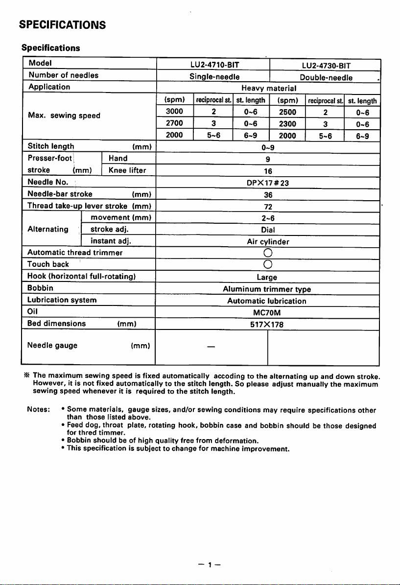
Model
Numberofneedles
Application
Max.
sewing
speed
Stitch
lengtli
Presser-footj
stroke
Needle
Needle-bar
Thread
Alternating
Automatic
Touch
Hook
Bobbin
Lubrication
Oil
Bed
No.
stroke
take-up
thread
back
(horizontal
dimensions
(mm)
lever
full-rotating)
system
Hand
Knee
stroke
movement
stroke
instant
trimmer
adj.
adj.
(mm)
(mm)
lifter
(mm)
(mm)
(mm)
(spm)
3000
2700
2000
LU2-4710-BIT
Single-needle
reciprocal
st. St. length
2
3
5-6
Aluminum
Heavy
0-6
0-6
6-9
DPX17#23
Air
Automatic
material
0-9
9
16
36
72
2-6
Dial
cylinder
o
o
Large
trimmer
lubrication
MC70M
517X178
(spm)
2500
2300
2000
LU2-4730-BIT
Double-needle
reciprocalst.
2
3
5-6
type
St. length
0-6
0-6
6-9
Needle
gauge
^ The maximum sewing
However, it is
sewing
Notes: *
not
speed
• Feed dog, throat plate, rotating hook, bobbin
•
•
fixed automatically to
whenever
Some
materials,
than
those
for
thred
Bobbin
This
timmer.
should
specificationissubjecttochange
(mm)
speed
is fixed automatically acceding to the alternating up and down stroke.
it is
requiredtothe
gauge
listed
above.
be of
high
the
sizes, and/or sewing conditions may require specifications
quality
free
stitch
stitch
from
for
- 1 -
—
length. So
length.
case
deformation.
machine
please
adjust
manually
and bobbin should be
improvement.
the
those
maximum
other
designed
Page 5
PREPARATION
m
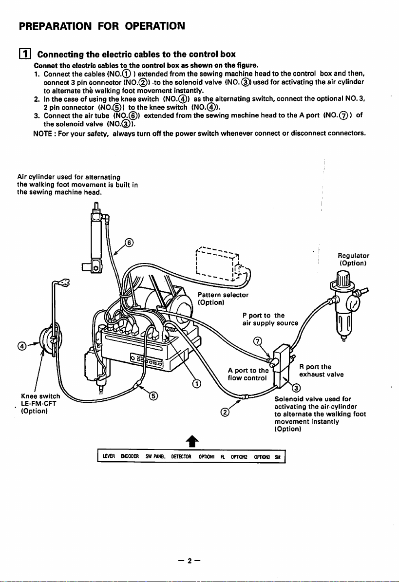
Connecting
Connet
the
1.
Connect
connect3pin
to
alternate
2.Inthecaseof
2
pin
connector
3.
Connect
the
solenoid
Air
the
the
NOTE : For
cylinder
walking
sewing
your
used
foot
machine
FOR
OPERATION
the electric cablesto the controlbox
electric
cablestothe
the
cables
(N0.(^ )
connector
the
walking
using
the
(N0.@)
theairtube
valve
(NO.©).
safety,
always
for
alternating
movementisbuilt
head.
(NO.d))
foot
knee
tothe
(NO.©)
control
extended
movement
switch
knee
extended
turn
off
in
boxasshownonthe
from
tothe
the
solenoid
instantly.
(N0.(^) asthe
switch
(N0.@).
from
the
the
power
switch
Pattern
(Option)
sewing
valve
alternating
sewing
figure.
machine
(NO.Cf))
machine
whenever
selector
P
air
head
tothe
used
switch,
head
connectordisconnect
porttothe
supply
control
for
activating
connect
the
totheAport (NO.©) of
source
box
theair
optional
connectors.
andthen,
cylinder
NO.
Regulator
(Option)
3,
Knee
switch
LE-FM-CFT
(Option)
LEVER
ENCODERSWPANEL
DETECTOR
- 2 -
A
porttothe
flow
OPIIONIH.0PTI0N2
control
OPT10N3
Solenoid
activating
to
alternate
movement
(Option)
SU
R
port
exhaust
valve
the
the
valve
used
air
the
walking
instantiy
for
cylinder
foot
Page 6
PREPARATION
FOR
OPERATION
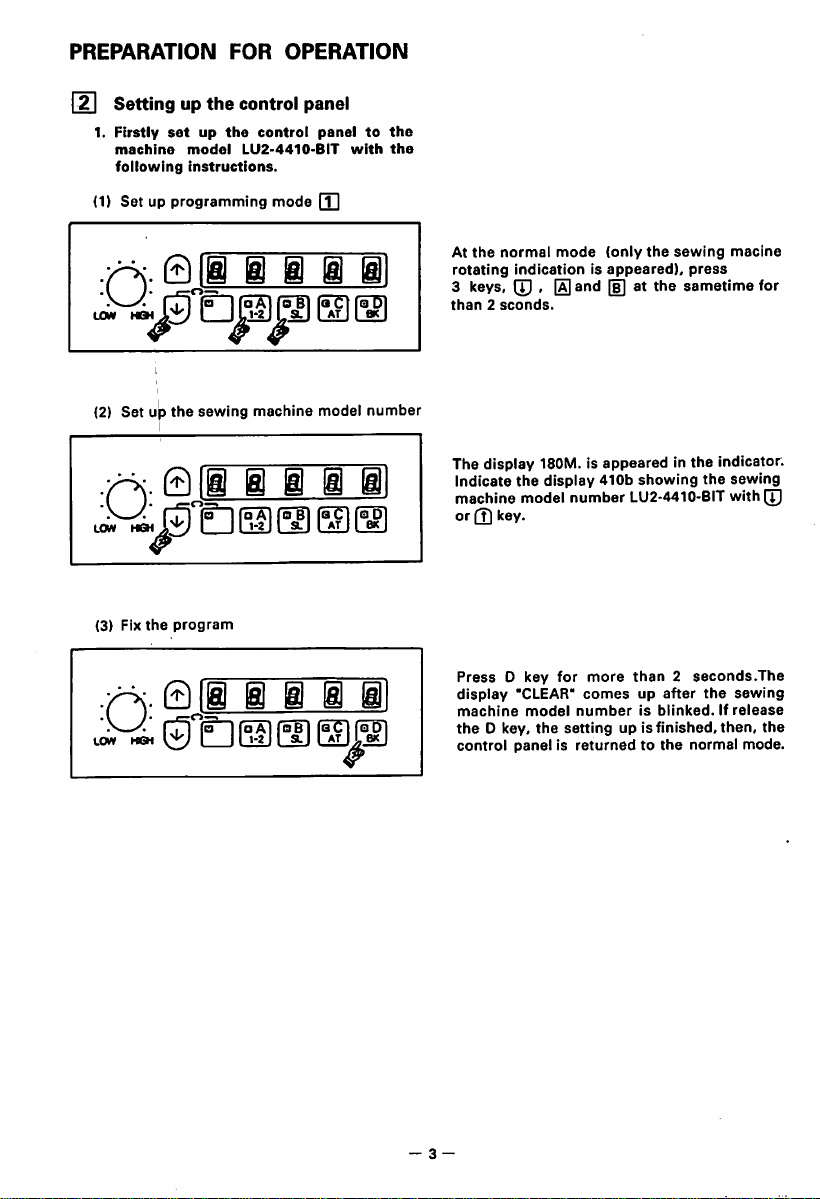
[2] Settingupthe
1.
Firstly
setupthe
machine
following
(1)
Set up programming mode (T]
.Q.
LOW
(2) Set up
HS
model
Instructions.
g)l§
the
sewing machine model
011
Q
LOW HGH
(3) Fix
the
program
.Q.
LOW
011
g
control
LU2-4410-BIT
control
panel
paneltothe
i i i
111
aC
AT
1 i 1 i
aC
AT
with
number
QD
1»
the
At
the
normal
mode
(only
the
sewing
rotating
3 keys,(p, and [i] at the sametime for
than2sconds.
The display 180M. is appeared in the indicator.
indicationisappeared),
Indicate
machine model
or (?) key.
the0key,
the
display 410b
PressDkey
display
'CLEAR*
machine
control
model
the
panelisreturnedtothe
number
for
setting
showing
LU2-4410-BIT with
more
than2seconds.The
comesupafter
numberisblinked.Ifrelease
up is
finished,
press
the
the
then,
normal
macine
sewing
[I]
sewing
the
mode.
3 —
Page 7
PREPARATION
2.
Exclusive
(1)
Settingupprogram
Press
(2)
Settingupprogram
setting
[T]
and[£]keysat the same timefor morethan 2 seconds and set the
Item
(Max.
H
(Medium
M
(Needle
RU
(Reversal
R8
Press [T]and keys at the
Item
11
(IN1)
12
(IN2)
I2A
(Alternate)
CD
(L
04
04L
05
ODC(L
output)
(ERR
(Logic
(KS3
output chopping)
(3) Setting up program [f]
Press3keys,CD>CDend[H
items.
0VL1
Only
VP2
(Voltageonthe
(Voltage on
VC2
two
items
Item
(Working
marked
FOR
OPERATION
for
LU2-4710/4730
[p]
high
speed)
speed)
back
up)
degree)
same
time for more than 2 seconds and
output)
change)
output)
keys
atthe sametimeformorethan 2secondsandset the
yield
point
the
yield point 1) 67 (80)
modeofVC2) LM
with
©mark
2)
are
^ismodel
Mismodel
different
Setting
3000
Setting
S7
101
ON
0T1
B
ON
0T1
ON
Setting
70
between
500
ON
following
44
4730
set
the following items.
items.
following
4730
the
model
4710
and
4730onthe
setting.
m Settingupthe
1.
When
control
2.
valve.
When
solenoid
control
valve.
the
the
activating
pulling
speedofthe
pushing
speedofthe
speedofthe air
air
cylinder,
air
cylinder,
4 —
cylinder
adjust
the
adjust
air flow of
the
exhaust
theAportonthe
solenoid
valveoftheRportonthe
Page 8
PREPARATION
0
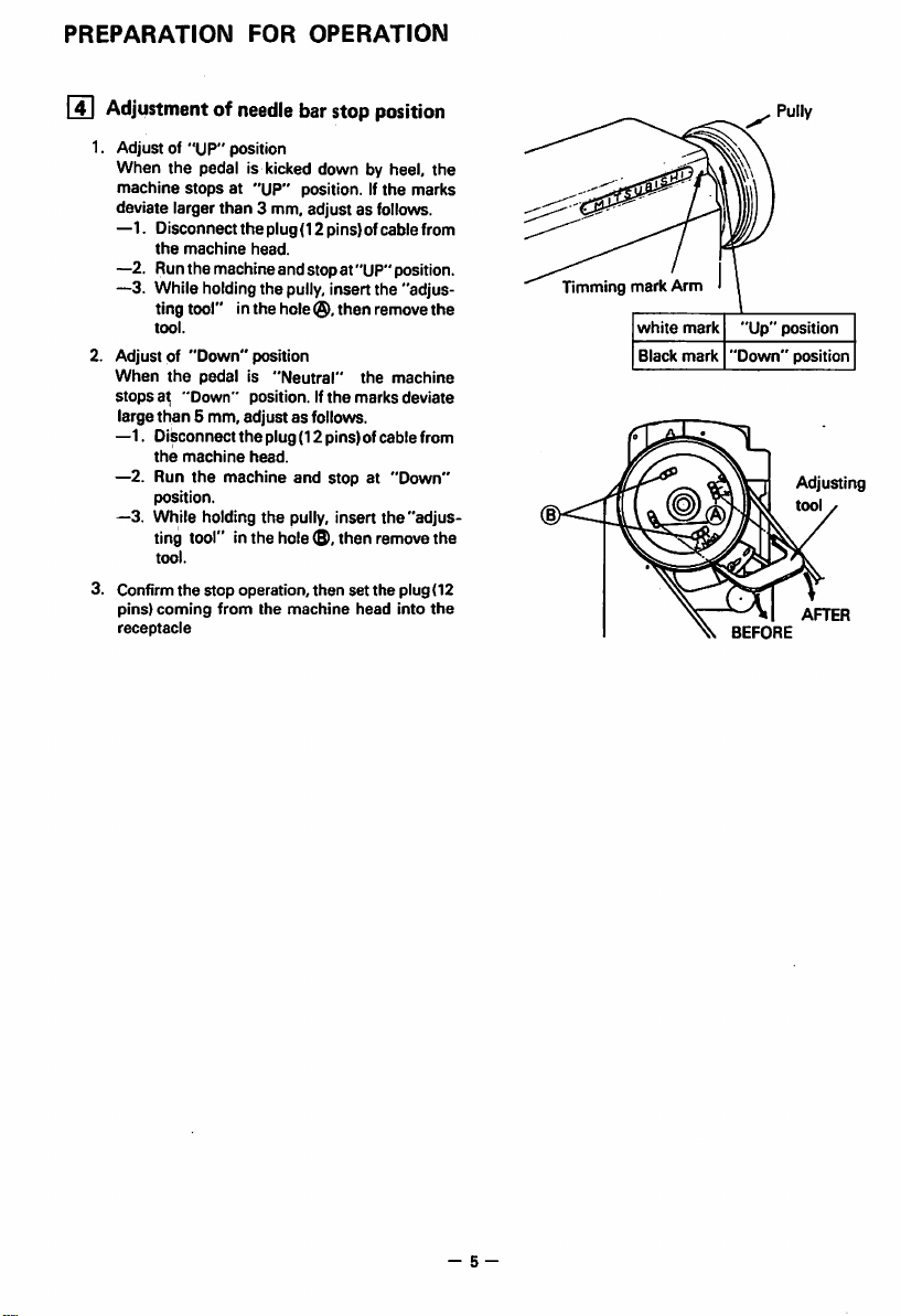
Adjustmentofneedle
FOR
OPERATION
bar
stop
position
1. Adjust of "UP" position
When
the
machine
pedal is kicked down by heel, the
stopsat"UP"
position. If
the
deviate larger than 3 mm, adjust as follows.
—1. Disconnect the plug (12 pins)ofcable from
the
—2. Run
machine
head.
the
machineand stop at "UP" position.
—3. While holdingthe pully,insert the "adjus
ting tool" in
tool.
2. Adjust of
When
the
stopsat"Down"
large
than
—1. Disconnect
the
machine
—2. Run
position.
—3.
While holdingthe pully,insert the "adjus
the
hole
then
"Down"
position
pedalis"Neutral"
position.Ifthe
the
marks
5 mm, adjustasfollows.
the
plug(12 pins) of cable from
head.
the
machine and stop at "Down"
remove
ting tool" inthe hole®,then removethe
tool.
3. Confirm the stop operation, then set the plug (12
pins)
coming
from
the
receptacle
machine
head
marks
the
machine
deviate
into
the
Timming
mark
white
Black
Arm
mark
mark
"Up"
"Down"
BEFORE
Pully
position
position
Adjusting
tool
AFTER
- 5 -
Page 9
CAUTIONS
ON
USE
[T]
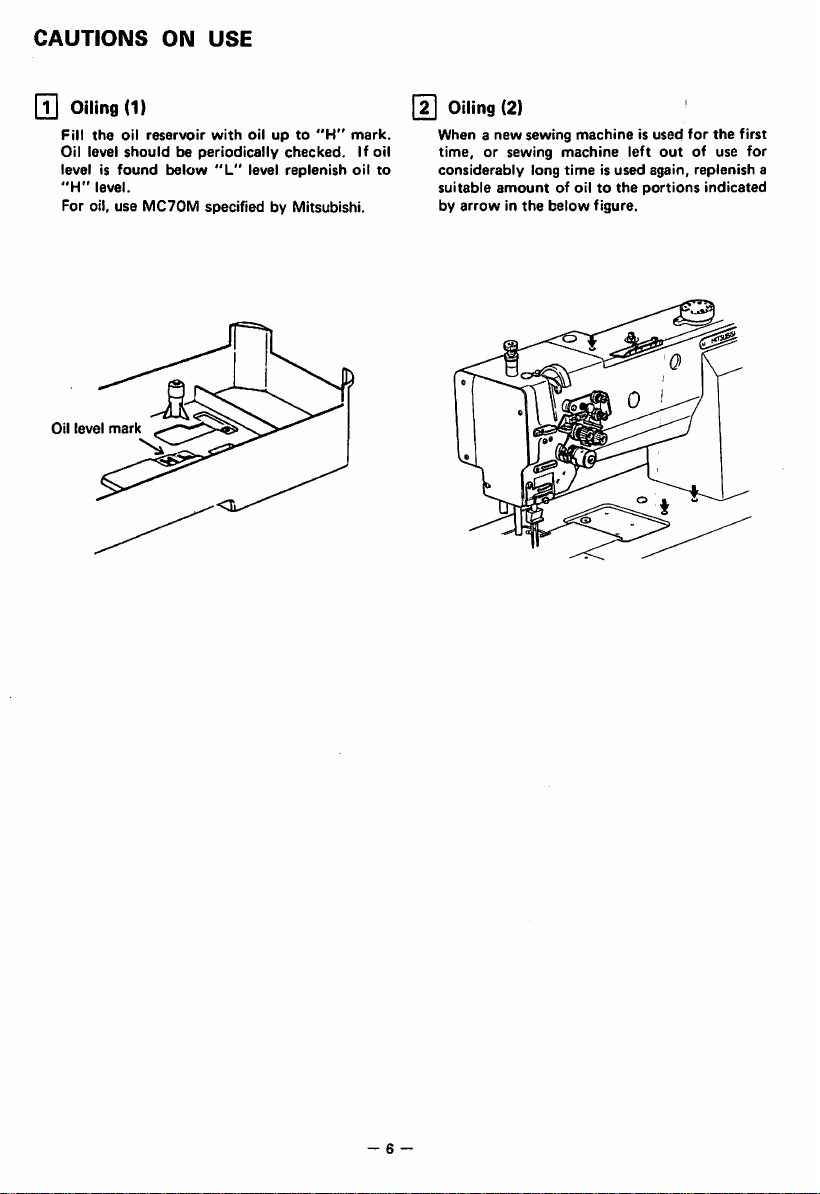
Oiling
(1)
Fill
the
oil
Oil level
level is
"H"
level.
reservoir
shouldbeperiodically
found
below
with
"L"
oilupto
checked.
level
replenish
For oil, use MC70M specified by Mitsubishi.
Oil
level
"H"
mark.
If oil
oil
Oiling (2)
When a
new
sewing
to
time,orsewing
considerably
suitable
amount
by
arrowinthe
machineisused
machine
long
timeisused
of oiltothe
below
left
figure.
out
again,
portions
for
the
of use
replenish
indicated
first
for
a
- 6
Page 10
CAUTIONS
ON
USE
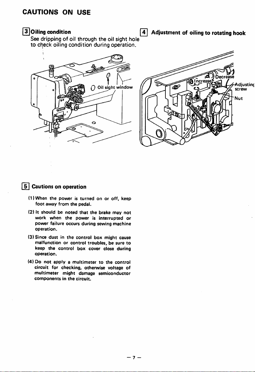
[^Oiling
condition
See dripping of oil through the oil sight hole
to
check
oiling
condition
i]
Cautionsonoperation
(DWhen
(2) It should be
foot
away
work
power
operation.
the
poweristurned
from
the
noted
when
the
failure occurs
(3) Since dust in the control box might cause
malfunctionorcontrol
keep
the
operation.
(4) Do
circuit
multimeter
components
control
not
applyamultimetertothe
for
checking,
might
in
the
during
operation.
f fv-
Oil
slaht
on or
pedal.
that
the
powerisinterrupted
during
troubles,besure
box
cover close during
otherwise
damage
circuit.
off,
brake may
sewing
machine
control
voltage of
semiconductor
window
keep
not
Adjustmentofoilingtorotating
Increase
o
or
to
hook
Nut
7 -
Page 11

HOW
TO
ADJUST
pn
Installationofneedles
DoubeNeedle
Insert
the
of
screw
of
I
Adiustmant:
•
•
•
needle
needle
needle
clamp
keeping
facetoface
Windingofbobbin
Tensionofwound
Conically
Lengthofwound
wound
the
upto
and
long
thread
thread
thread
AND
the
tighten
groove
thread
USE
bottom
the
side
Slack
Move
Loosen
and
THE
MACHINE
Note:
Before
installing
nsufficient
Insertion
Note:
When
bobbin
windingisrecommended
the
thread
guide
the
thread
tighten
length
the
screwtodecrease
the
needles,besuretoturn
Needle
threadiswound,
for
toward
adjusting
polvester
smaller
screwtoincrease
lengthofthread.
distorted
X
/%i
keep
the
presser
thread
diameterofwound
and
off
the
power.
rs
Long
groove
left
side
foot
lifted.
nylon
thread.
thread
lengthofthread
layer.
i
Winding
adjusting
i
tension
screw
Page 12
HOW
[si
[4]
TO
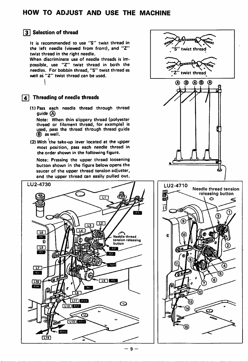
Selection of thread
It is
recommended
the
left
twist
When
possible,
needles.
wellas"Z"
needle
threadinthe
discriminate
use
For
Threadingofneedle
(1)Pass
(2)
each
guide
(g)
Note: When
thread or filament
used, pass
(§) as well.
With
Vhe
most
position, pass each needle
the
order
Note:
Pressing
button
showninthe
saucerofthe
and
the
LU2-4730
ADJUST
to
(viewed
right
useofneedle
"Z"
twist
bobbin
twist
thread
needle
thin
the
thread
take-up
showninthe
the
upper
upper
thread
AND
use
from
needle.
threadinboth
thread,
canbeused.
"S"
front),
"S"
USE
twist
thread
and
threadsisim
twist
thread
"Z"
threads
thread
through
slippery thread (polyester
thread,
for example) is
through
lever
located
following
upper
thread
figure below
thread
tension
can easily
thread
at the
thread
figure.
loosening
opens
adjuster,
pulled
thread
guide
upper
out.
THE
in
the
as
in
the
MACHINE
*S"
'Z"
® d)
AjIjI
LU
2-4710
twist
twist
thread
thread
®(D
Needle
®
1
thread
releasing
o
tension
button
Neddie
thread
tension
releasing
button
©
- 9 -
Page 13
HOW TO
]
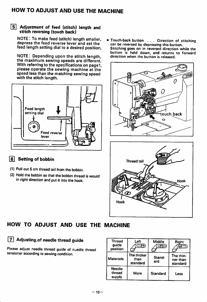
Adjustmentoffeed
ADJUST
AND
(stitch)
USE
THE MACHINE
length
stitch reversing (touch back)
NOTE:
To make feed (stitch) length smaller,
depress
the
feed
reverse
lever
and
set
feed length setting dial to a desired position.
NOTE:
the
Depending upon
maximum
sewing
the
speeds
stitch length,
are
different.
With referringto the specifications on page1,
please
operate
speed
less than the matching
with
the
Feed
setting
the
stitch length.
length
dial
Feed
reverse
lever
sewing
I
machineatthe
sewing
and
the
speed
Touch-back button . . . Direction of stitching
can be reversed by depressing this
Stitching
button
direction
goesonin
is held
when
reversed
down,
the
and returnstoforward
buttonisreleased.
button.
direction
while
the
\
touch
back
Settingofbobbin
(1) Pullout 5 cm thread tailfromthe bobbin.
(2)
Hold
the
bobbin
Inrightdirectionand put it intothe
so thatthe
HOW
0
TO
ADJUST
Adjusting,of
needle
bobbin
AND
thread
thread iswould
hook.
USE
THE
guide
Please adjust needle thread guide of noedle thread
tensioner accordingto sewing condition.
-10-
MACHINE
Thread
guide
position
Materials
Needle
thread
supply
Thread
The
standard
Left
thicker
than
More
tail
Middle
Stand
ard
Standard
Right
The
ner
standard
Less
thin
than
Page 14

HOW
TO
ADJUST
AND
USE
THE
MACHINE
[S]
Threadingofbobbin
(l)Put
bobbin
thread
Into
the
lug(I)and extend itabove the bed.
Thread
Opener
<2)
While holding
rotate
By pulling up
figure,
bobbin
and
led
the
handwheel
the
thread
backward.
the
two needle threads by left hand,
one
the
needle
bobbin
and
threads,asshowninthe
threads
needle
thread
threads
slit^l>,pass
turn
willbelifted. Both of
under
Thread
by right
hand.
shouldbealigned
the
Balanceofthread
AO
B X
C X
ITl]
Needle
Turn
the
thread
edle
thread
thread
tension.
tension
tension
Balanced
Tight needle or
bobbin
Loose
bobbin
tension
adjust
nutstoadjust
tension
loose
tension
needleortight
tension
Pretension
Tighten
Loosen
Tighten
the
ne
^
Tension
screw
Tension
adjusting
adjusmtnetof bobbinthreads
Loosen
Tighten
[ia
Adjustment of presser foot pressure
Pressuretofabric(s)
pressure
-11
adjusting
Weaken
Loosen
Thread
tension
adjust
nut
canbeadjustedbyturning
screw.
^
Tighten
C
the
Page 15

HOW
TO
ADJUST
|j3|
Adjustmentofthread
AND
USE
take>up
THE
spring
1) Adjustment of thread take-up spring length
•To
adjust the thread take-up spring (D for the
left-hand
thread,
loosen
the
stopper
stop
screw (D and move the stopper (I).
•To
adjust the thread take-up spring ® for the
right-hand thread, loosen
the
stopper
stop
screw © and move the stopper ®.
2) Adjustment of thread take-up spring strength
•When
adjusting
loosen
the
Arm and turn next
Tighten
the
the
adjustment.
•When
adjusting
lock
lock
the
left-hand
nut
(2)
and
the
nut®and
the
right-hand
thread
screw
screw
thread
spring,
® in
(Q)
spring,
the
adjusting shaft
the
the
®.
after
loosen the screw ® and turn next the adjust
nut Tighten the screwi ® after the
adjustment.
MACHINE
decrease
ncrease
w
-
Right
side
-
Right
side
Loosen
Tighten
-
Left
side
ll^
AdjustmentofOutside
and
Inside
presser
1. Adjustment of alternating movement
(1)
The
alternating
pressre
be adjusted by using the adjusting dial
located on
foot
the
and
top
movement
inside
foot
presser
cover.
presserfoot
onthe
(2) Face the desired number printed on the
d|al to
the
top
(3) Thenumber printed onthe dialrepresents
the
presser
matching
cover.
possible
foot and inside presser foot from
mark
locatedonthe
protrusionofthe
the throat piate when the aiternating
movementsonthese
(4)
If the
alternating
set,
they can be readjusted up to 2.0-
6.0mm
are
evenly
movements
are
putside
foot
outside
set.
evenly
can
Alternating
adjusting
Matching
—
12—
mark
Rubber
dial
' ^
plug
stroke
Page 16

HOW TO
2. To
movements
and
(1) For
ADJUST
change
the
between
Inside
presser
example,toincrease
inside
presser
of
the
outside
(l)
Remove
top
throat
(3)
Loosen
(right)
(4)The
side
with
the rubber pluglocatedonthe
cover.
Rotate
the
presser
footisslightly
plate.
set
upper
feed
built-in
presser
the
throat
AND USE THE MACHINE
balanceofthe
the
outside
foot.
and
decrease
foot:
until
raised
(§)
located
rock
untilitmakes
plate.
Then,
the
foot,
presser
pulley
screw
lifting
spring pullsdown the out
foot
screw@.
(5) Thiscompletesthe adjustment,i.e.,the
protrusionofthe
has
been
And,
presser
same
(2) As a
contrary
riseofinside
the
riseofthe
First,
rotate
presserisslightly
the
foot
distance.
decreased
vertical
has
been
case
presser
outside
the
pulley
raised
outside
by a
motionofthe
increasedbythat
(1),todecrease
foot,
presser
until
from
plate. Next, loosen screw(§).
tightenscrew@.This decreases the rise
of
the
inside
presser
foot.
alternating
presser
riseofthe
the
the
outside
from
on the
shaft
contact
tighten
presser
set
distance.
and
increase
foot:
the
the
Finally,
foot
rise
the
crank,
set
foot
inside
the
inside
throat
Outside
presser
foot
Inside
Rubber plug
Upper
shaft
presser
2.0-6.0mm
feed
crank
foot.
lifting rock
(right)
Mounting
Turn
(1)
the
position.
(2) In
this
locatedonthe
in
the
showninthe
the
the
thread
st^te,
upper
Upper
balance
take-up
eccentric
figure.
eccentric
wheelbyhand
leveratthe
remove
the
arm.
Locate
feed
And
feed
rubber
No.2
lifting
tighten
lifting cam
to bring
lowest
plug
screw'A"
cam
it.
as
—13—
No,1
No,2
screw'A"
Upper
eccentric
liltingcam
screw
feed
Page 17

HOW
TO
ADJUST
AND
^ Instantalternatingswitch
During
the
sewing
hasastep,
the
alternating
ly
becomes
Hit
once,
(Blinking
Hit
twice,
ON
LED
OFF
T
hit
the
strokeofthe
much
lamp)
operation, ifa
instant
alternating
biggertoget
The
down
highest
Is
the
ewing
from
The
down
the
ed
stroke
USE
THE
sewing
switch,
walking
foot
over
the
alternating
movement
(It is
highest
machineisshipped
the
alternating
movement
normal
with
adjusting
adjusted
when
factory.)
stroke
the
becomes
becomes
alternating
dial.
material
then
instant
step.
up
and
6mm
the
up
and
controll
MACHINE
s-
Stopper
.Alternating
.adjusting
screw
Instant
alternating
stroke
dial
switch
NOTE1:The
2: It
Tfl The
instant
The
maximum
the
instant
be
adjusted
right
figure.
©The
maximum
when
factory.
If
the
to
make
procedures.
1.
2.
3.
4.
knee
the
instant
also
and
down
only
nating
stopper
alternating
alternating
with
the
sewing
maximum
smaller
Set
the
dialtothe
Loosen
Tighten
with
Tighten
switch
alternating
canbeset
movement
while
pressing
switch.
screw
alternating
functionisactivated
the
stopper
alternating
machineisshipped
alternating
somehow,
alternating
desired
the
nut
shownonthe
the
stopper
the
pin.
the
nut.
also
canbeused
switch.
the
alternating
most
the
instant
for adjusting
stroke.
stroke
the
time
screw
showonthe
stroke
is fixed at
strokeisrequired
take
the
following
stroke
screw
adjusting
right
untilithits
numberofthe
highest
alter
when
6mm
from
stroke.
figure.
the
can
the
as
up
Stopper
Screw
"V
E3
r
Nut
.
red
mark
.(position
6mm)
at
E
-14-
Page 18

HOW
TO
ADJUST
5^
Installing
Should
it be
regulator
procedure
CAUTION;Ifthe
positioned,
maybetoo
machine
(1)
Set the
wall
illustrated to
between
operation.)
necessarytodismount
bracket and its related
explained
the
operation.
clearance
locatedonthe
of
the
feed regulator bracket is poorly
resultant
short
the
the
these
Feed
below.
or long,
between
regulator
machine
left. (Use a
parts.
AND
regulator
alternating
causing
special
shaft
armto42.6mm
42.6mm
This
facilitates
USE
THE MACHINE
bracket
and
the
parts,
use
movements
defective
screw
and
the
spacer
(2)Withthe feed regulator stud held-as explained
step
(1)
above,
adjust
the
feed
in
bracket.
clearance of
pin(D
and
the
IISJ
Adjustment
sensing
(1)
(2) Remove all
1
(3)
set
(4) Turn ON
tion
lay VCat
(5) Loosen the slotted head bolt(0)of the potenti
ometer
At
any
(6) Fix
aft special
sewing
(Itisrecommendedtouse
42.6mm
(7)
Turn
displayVCindicates
(8) Tighten the slotted head bolt(Q)of
ometer
At
any
(9) Make
icates
If
from
again.
(10)Turn OFF
(11)Put
(12)Connectallthe
condition.
This
adjustment
2.3mm
the
arm.
located
top
Tighten
onthe
cover
ofthe
between
feed
mounting
screws
alternating
potentiometer
(Please
refertothe
Limi-servoX
Please
note
proper
Turn
connector.
Remove
the
this
the
this
the
set
thatiffault
sewing
OFF
the
the
the
alternating
the
panelofthe
the
crank.
time,
bending
torquetothe
distance between the feed adjusting
screw®
machine
for
quick
the
potentiometer
crank.
time,
bending
torquetothe
sure
again
280-289.
display
280-289,
the
the
top
cover
the
alternating
instruction
BMFY
also.)
speed
can
power
switch.
connectors
top
coverinthe
dial for
power
switch
control box to
programming
please
pay
and
arm
42.6mm.
fixing.)
280~289.
please
pay
that
the
indicates
adjust
the
power
switch.
backinthe
dial
for
connectors
the
scale
attention
potentiometer
the
shaftsothat
attention
potentiometer
input
the
potentiometer
except
then,
scale
back to
should
the
periphery of
regulator
face
located
manual
adjustment,
not
obtained.
the
condition
2.
set
the
the
input
mode
E.
nottogive
inner
wall of
the
spacer
the
nottogive
display VC ind
different
condition
2.
the
regulator
insure
bracket
stroke
optional
which
opera
shaft.
sized
the
input
potenti
shaft.
number
shaft
which
original
feed
side
the
the
disp
the
for
sh
the
@
as
on
-15-
Feed
n.
2.3mm
Feed regulator bracket
/
regulator
shaft
k
42.6mm
(A)
m
a
f
Potentiometer
©
42.6mm
Page 19

HOW TO ADJUST AND USE THE MACHINE
H
Timing
and
(1) Set feed length (stitch length) to
feed
needle
setting
between
motion
dial.
rotating
hook
motion
"6"
on the
(2)When needle is lifted 2.4mm from the lower
dead point, as shown in Figure, the follow
ing
positional relationship should be main
tained.
—The
upper edge of needle eye should be
2.3mm
below
the
hook
—The
hook point should be located at the
centerofneedle
—Gap
between the hook point and the side
faceofneedle
shouldbe0.05mm.
point.
axis.
(3) Needle/rotating hook position can be ad
justedasfollows.
(For easy adjustment, it is recommended
that the presser foot, throat plate and feed
dog assembliesare removed.)
•
Positioningofhook
(1)
When
the
smaller
crossed
side
and
left
larger wheel so
former
gear
thatofthe
(2) Tighten each
for
set
(3)
*Tofinely
screw,onthe
Approximate
"C"
screwofhook
the
needle
position.
motion
screwoflarger
wheelinits
from
adjust
and
1mmto2mm.
point
needleisat
side
DOWN
herical gearsonthe
shouldbeengaged
that
the
comesonthe
latter
gear on
"S"
positionofhook
when
hook
gear
axial
the
screw, where is punched
hook
shouldbefound
the
needleisat
timing
between
motion,
wheel
direction
position,
"S"
screw of the
front
side,
reverse side.
shaft.
the
loosen
and
move
withinarange
with
close
DOWN
needle
the
the
the
right
the
and
to
set
gear
Gap
and
Needle
2.4mm
needle lower ^
dead
Center
needle
between
upper
2.3mm
lift:
from
point
of
axis'
Hook
)
1 ~
hook
2mm
*
point
point
0.05mm
edgeofneedle
eye
1 ~
I
2mm
16—
Needle
position
DOWN
Page 20
OPERATION
gOl
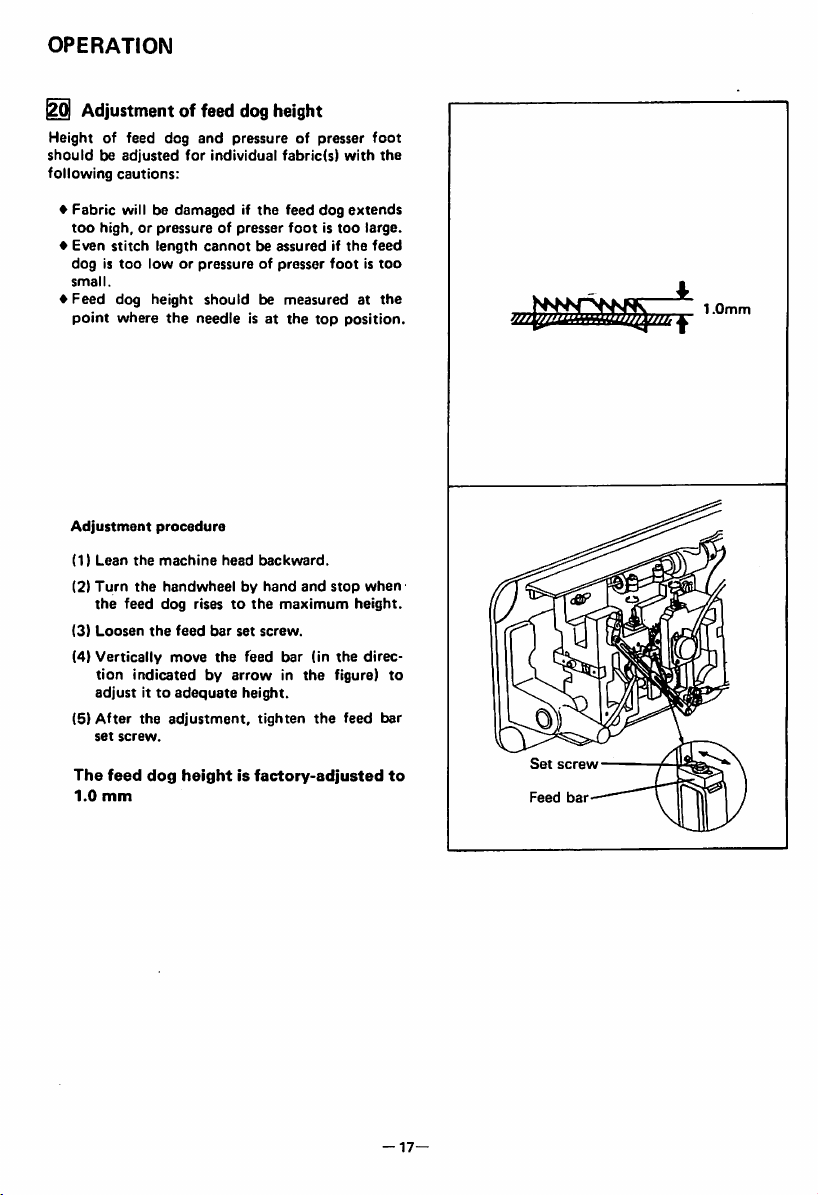
Adjustmentof feed dogheight
Height
of feed dog
shouldbeadjusted
following
cautions:
♦
Fabric
will be
too
high,orpressureofpresser
♦
Even
stitch
dogistoo
small.
♦
Feed
dog
point
where
and
pressure
for
individual
damagedifthe
length
cannotbeassuredifthe
loworpressureofpresser
height
shouldbemeasuredatthe
the
needleisat
of presser
fabric(s)
feed
dog
footistoo
the
top
foot
with
the
extends
large.
feed
footistoo
position.
mr-
I.Omm
Adjustment
(1)
Lean
(2)
Turn
the
feed
(3)
Loosen
(4)
Vertically
tion
adjustitto
(5)
After
set
screw.
The
feed
1.0
mm
procedure
the
machine
the
the
head
backward.
handwheelbyhand
dog
risestothe
feed
bar
set
screw.
move
the
feed
and
maximum
bar
indicatedbyarrowinthe
adequate
the
adjustment,
dog
heightisfactory-adjusted
height.
tighten
(in
the
stop
the
figure)
feed
when
height.
direc
bar
to
Set
Feed
screw
bar
to
—
17—
Page 21

HOW
TO
ADJUST
AND
USE
THE
] Relationship between rotating hook
motion
When the
moved
relationship
take-up
follows:
for
lever
and
timing
its
between
take-up
belt
replacement,
rotating
motion
lever
(toothed
should
motion
belt) was re
for
example,
hook
be
motion
adjusted
MACHINE
the
and
as
(DTurn
(2)
(3) If
]
(1)Turn
(2)
(3) If
the
take-up
Lean
sure
timing
the
black
stallitagaintoadjust.
balance,
leverisliftedtoits
the
machine
the
arrow
belt
bossoflower
the
timing
line,
Relationship
opener
motion
the
the
sure
@ and the
the
gapistoo
holder
balance
from
when
remotely
Make
holder
0.2mm.
opener
tionofthe
wheel
and
head
backward
(timing
is in
markisnotinline
remove
between
opener
the
gap
mark)
line
with
shaft
bearing.
the
timing
hook
wheelbyhand
holderislocated
throat
between
openerisapproximately
largeorsmall,
set
screw
opener.
@ and
upper
the
plate.
the
stop
when
dead
and
putonthe
black
belt
motion
and
bobbin
loosen
adjust
line
with
and
the
point.
make
the
and
stop
most
case
posi
on
in
the
Black
lower
Approx.
lineonboss
shaft
bearing
0.2mm
Timing
belt
-Timing
belt
Timing
mark
sprocket
-18-
Opener Screw (gi
Opener
holder
Page 22
HOW
TO
ADJUST
AND
USE
THE MACHINE
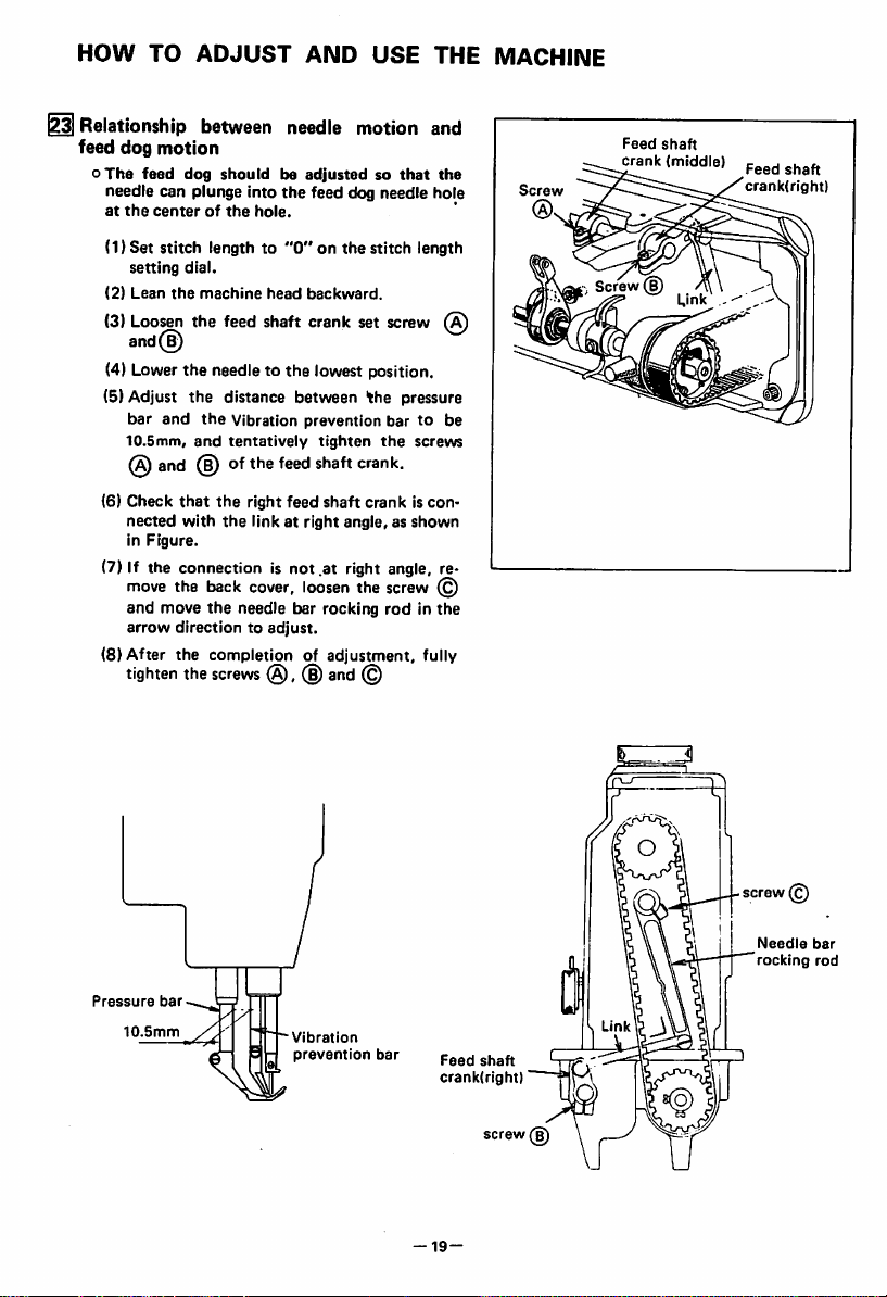
IRelationship between
feed
dog
motion
oThe
feed
dog
needle can plunge into
at
the
centerofthe
(1) Set stitch length to
setting
(2)
Lean
(3)
Loosen
shouldbeadjustedsothat
dial.
the
machine
the
feed
needle
the
feed dog needle hole
hole.
"0"
on the stitch length
head
backward.
shaft
crank
motion and
set
and(^
(4) Lower the needle to the lowest position.
(5) Adjust
(6) Check
(7) If the connection is not .at right angle, re
(8) After the completion of adjustment, fully
the
bar
and
10.5mm,
@
and
nected
in
Figure.
distance between
the
Vibration prevention bartobe
and
tentatively
@ of
the
feed
that
the
with
right feed
the
linkatright
the
tighten
shaft
crank.
shaft
crank is con
angle,asshown
move the back cover, loosen the screw (£)
and
move
the
needle
arrow
directiontoadjust.
tighten
the
screws@,(§)
bar rocking
and
©
screw
pressure
the
screws
rodinthe
the
Screw
(A)
Feed
crank
Screw
®
shaft
(middle)
Feed
shaft
crank(right)
Pressure
10.5mm
'©
Needle
bar
rocking
rod
bar
Vibration
prevention
bar
Feed
crank(right)"rpi
shaft
screw(D
-19-
Page 23

HOW
TO
ADJUST
AND
USE
THE
MACHINE
M SAFETY
Safety
the
the
CLUTCH
clutch
hook
and
threadiscaught
machineisloaded
ation.
1)
FUNCTION
1) When
pulley
hook
rotate.
2) Clean
into
3)
Turn
whether
properly,
2) HOW
1) While
opposite
balance
from
OF
the
safety clutch acts,
willbeunloaded,
shaft
will
Stop
the
the
thread
the
hook.
the
cog
the
hook
place
TO
SET
pressing
sideofbedbyleft
wheel
youasshowninthe
2) The balance wheel will
plate,
but
3) Release
4) As
3)
FORCE
CLUTCH.
1)
2) To
3)
firmly.
showninthe
deviceIsset.
The
smallest
tric
pin
The
white
adjust
loosen
pin.
After
the
set
the
APPLIED
force
appliedtothe
when
faces
force
mark
the
the
adjustment,
screw.
turn
push
the
proportionally
faces
the
set
DEVICE:
deviceisinstalledtoprevent
cog
belt
from
damageincase
into
the
hook
when
abnormally
SAFETY
stop.
operationofmachine.
thoroughly
belt
hubbyhand,
shaft
the
clutch
THE
down
slowly
CLUTCH.
then
the
The
arm
shaft
which is
rotates
deviceasfollows.
SAFETY
the
push
hand,
by
right
buttononthe
figure.
stop
the
balance
button.
Figure,
the
safety
TO
THE
safety
the.white
clutchIsthe
markofthe
centerofthe
increasesasthe
the
outside.
force,
slide
and
make
turn
the
the
suretofasten
screw,
during
the
by the gear
wheel
lower
timing belt,
the
oper
cog belt
rotation
only
will
caught
and
check
lightly
and
CLUTCH.
turn
the
hand
away
more
clutch
SEFETY
eccen
shaft.
eccentric
Safety
clutch
belt
pulley
belt
hub
of
Balance
wheel
Push
button
Gear
plate
White
Strengtheni^Screw
Weaken
Lower
-20-
Mark
Shaft
Eccentric
Timing
Pin
Eccentric
Belt
Pin
Page 24
OPERATION
I
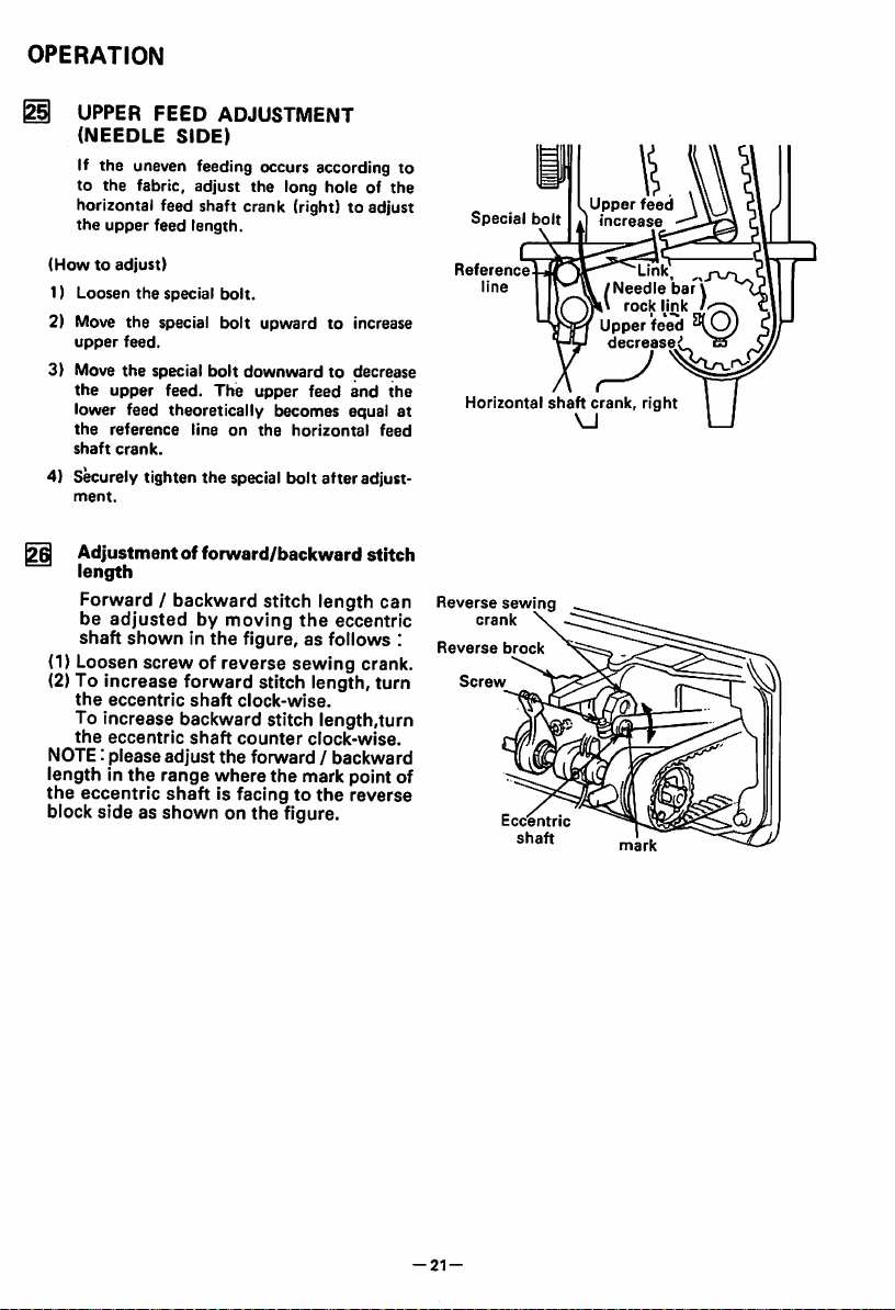
UPPER
(NEEDLE
If the uneven feeding occurs according to
to the fabric, adjust the long hole of
horizontal feed shaft crank (right) to adjust
the
upper
FEED
SIDE)
feed
length.
ADJUSTMENT
the
Special
bolt
.Upperfeed
»|
increase
\
(Howtoadjust)
1) Loosen
the
special
bolt.
2) Move the special bolt upward to increase
upper
feed.
3) Move
the
special
bolt
the
upper
lower feed theoretically becomes equal at
the
shaft
feed.
reference
crank.
downward to decrease
The
upper
lineonthe
horizontal
feed
and
4) Securely tighten the special bolt afteradjust
ment.
^
Adjustmentofforward/backward
stitch
length
Forward / backward stitch length
be
adjustedbymoving
shaft
showninthe
(1) Loosen
(2) To
the
screwofreverse
increase
eccentric
forward
shaft
the
eccentric
figure, as follows :
sewing
crank.
stitch length,
clock-wise.
To increase backward stitch length,turn
the
eccentric
NOTE: please
length in
the
eccentric
shaft
adjust
the
range where the mark point of
shaft
counter
the
is facingtothe
clock-wise.
forward / backward
reverse
block side as shown on the figure.
the
feed
can
turn
Reference
Horizontal
Reverse
crank
Reverse
Screw
sewing
brock
Eccentric
shaft
shaft
VJ
/Needle
Upper
decrease
crank,
rock
mark
Link
right
Mnk
feed
ba^V
*
-21-
Page 25
HOVyTOADJUST
13
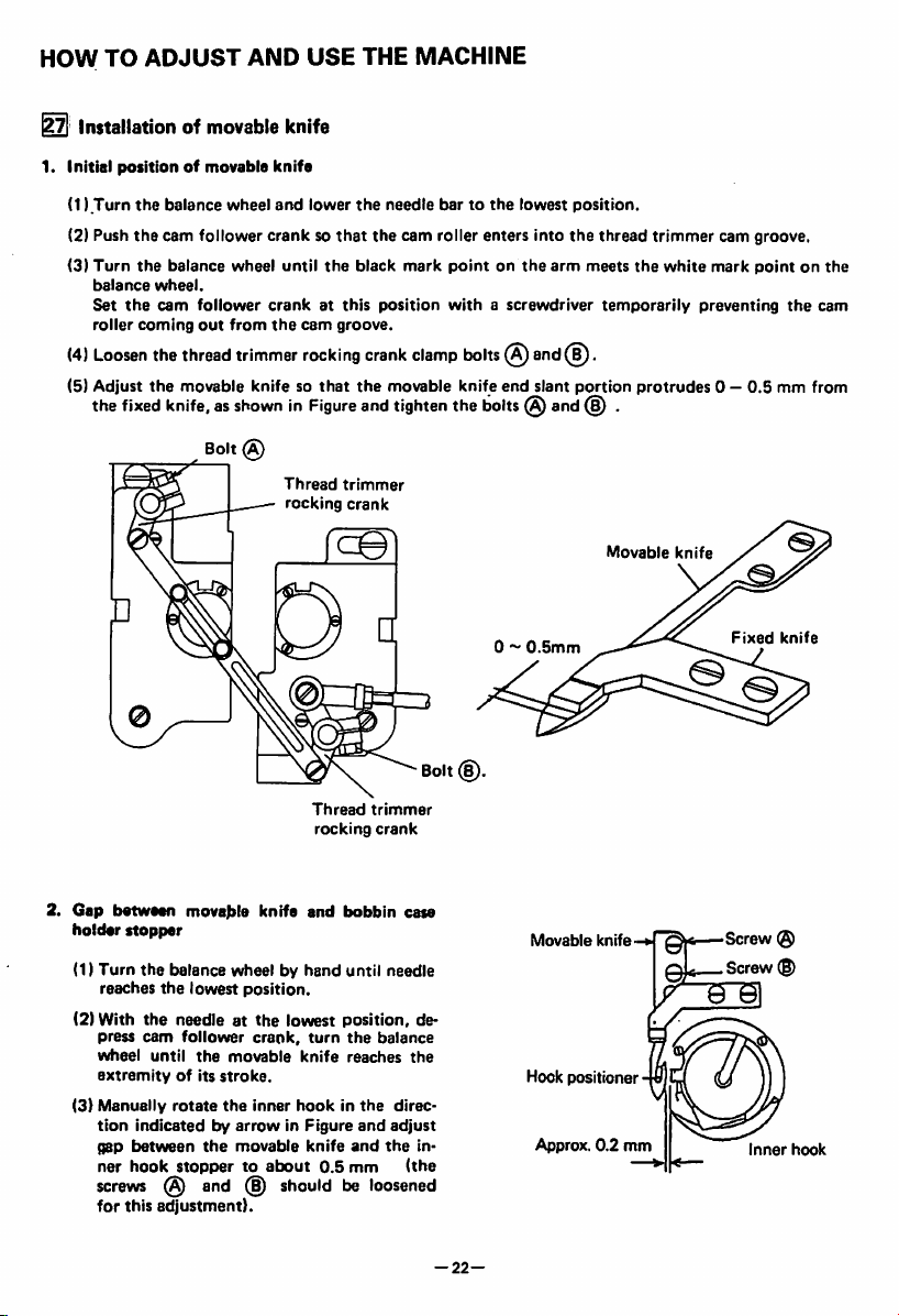
Installationofmovable
1. Initial positionofmovable
(1)
Turn
the
balance
wheel
(2) Push
(3)
(4)
(5) Adjust
the
Turn
the
balance
Set
the
roller
coming
Loosen
the
fixed
cam follower
balance
wheel.
cam
the
the
wheel
follower
out
from
thread
trimmer
movable knife so
knife,asshowninFigure
Bolt
<g)
AND USE THE MACHINE
knife
knife
and
lower
the
needle
bartothe
cranksothat
until
crankatthis
the
cam
rocking
Thread
rocking
the
groove.
that
the
cam roller enters into
black
mark
position
crank
ciamp
the
movable knife
and
tighten
trimmer
crank
pointonthe
withascrewdriver
bolts
@ and(^.
end
the
bolts@and
lowest
slant
position.
the
arm
portion
thread
meets
the
temporarily
(§) .
trimmer
white
protrudes
cam groove.
mark
pointonthe
preventing
0 —
0.5
the
cam
mm from
2.
Gap
holder
(1)
(2) With
(3)
between
Turn
reaches
press
wheel
extremityofits
Manually
tion
gap
ner
screws
for
movable
stopper
the
balance wheel by
the
lowest
position.
the
needleatthe
cam
follower
until
rotate
indicatedbyarrowinFigure
between
hook
stoppertoabout
@
this
adjustment).
the
the
and
movable
stroke.
the
movable
(|)
crank,
inner
Thread
trimmer
rocking
crank
knife
and
bobbin
hand
until needle
lowest
position,
turn
the
0.5
balance
reaches
and
and
mm
knife
hookinthe
knife
shouldbeloosened
case
direc
adjust
the
(the
Bolt(B).
de
the
in
0 ~
0.5mm
Movable
Hookpositioner
Approx.
Movable
knife-
0.2
mm
knife
Fixed
Screw
Screw
Inner
knife
hook
—
22—
Page 26
HOW
TO
ADJUST
AND
USE
THE
MACHINE
Bracket
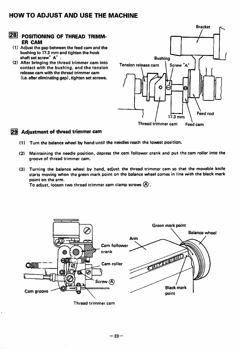
POSITIONING
ER
bushing
shaft
CAM
the
to 17.3mmand
set
screw'A'.
(1) Adjust
(2) After bringing
contact
with
release
cam
(i.e.after eliminating
OF
THREAD
TRIMM
gap between the feed cam and the
tighten
the
hook
the
thread
with
the
bushing,
the
thread
gap).
trimmer
tighten
and
trimmer
the
set
cam
tension
cam
screws.
into
Tension
Bushing
release
cam
t / 17.3
Thread
trimmer
Screw
cam
'A'
mm
Feed
I Adjustment of thread trimmercam
<1)
Turn the balance wheel by hand until the needles reach the lowest position.
(2) Maintaining the needle position, depress the cam follower crank and
grooveofthread
trimmer
cam.
(3) Turning the balance wheel by hand, adjust the thread trimmer cam so
starts moving when the green mark point on the balance wheel comes in line with the black mark
pointonthe
To
adjust,
arm.
loosen
two
thread
trimmer
cam
clamp
screws
® .
put
the cam roller into the
that
Feed
\
rod
cam
the movable knife
Cam
groove
Thread
Screw (A)
trimmer
Cam
crank
Cam
cam
-23—
follower
roller
Green
mark
Black
point
point
mark
Balance
wheel
Page 27

HOW
TO
ADJUST
5ol
Adjustmentofneedle
(1)
Turn
the
AND
threads
balance wheel by
USE
hand
THE
tension
until
MACHINE
release
the
needles reach
assembly
the
lowest position.
(2) Maintaining the needle position, depress
grooveofthread
(3) Turning the balance wheel by hand, adjust
close when the white mark point on the balance wheel comes inline with the black mark point
on
the
arm.
To
adjust,
(4)
Opening
the
convexed
To
adjust,
(5)
Make
fine
(6)
Loosen
thenut(§)
trimmer
loosen
degreeoftension
portionofthread
loosen
two
the
cam.
tension
screws
release
disc
© and
adjustmentbyloosening
and
make
the
N
shouldbeadjusted
release
the
the
cam
clamp
cam,
as shown in Fig.
draw
the
thenut{§).
outer
casing
cam follower crank and
thread
tension release cam so
screws
@.
withthe
tension
wire.
approach
rightwardtoincrease
White
put
release
mark
the
that
roller
point
(D|
Cam
Thread
release
Screw
Roller
Thread
release
tension
lever
(§)
(D
cam
Thread
cam
trimmer
(D
_
Screw©
crank
Cam
follower
roller
Outer
casing
Black
point
mark
cam roller into the
the
tension disc
(g)
mounted
the
opening
value.
Balance
wheel
on
-24—
Page 28
HOW
TO
ADJUST
AND
USE
THE
MACHINE
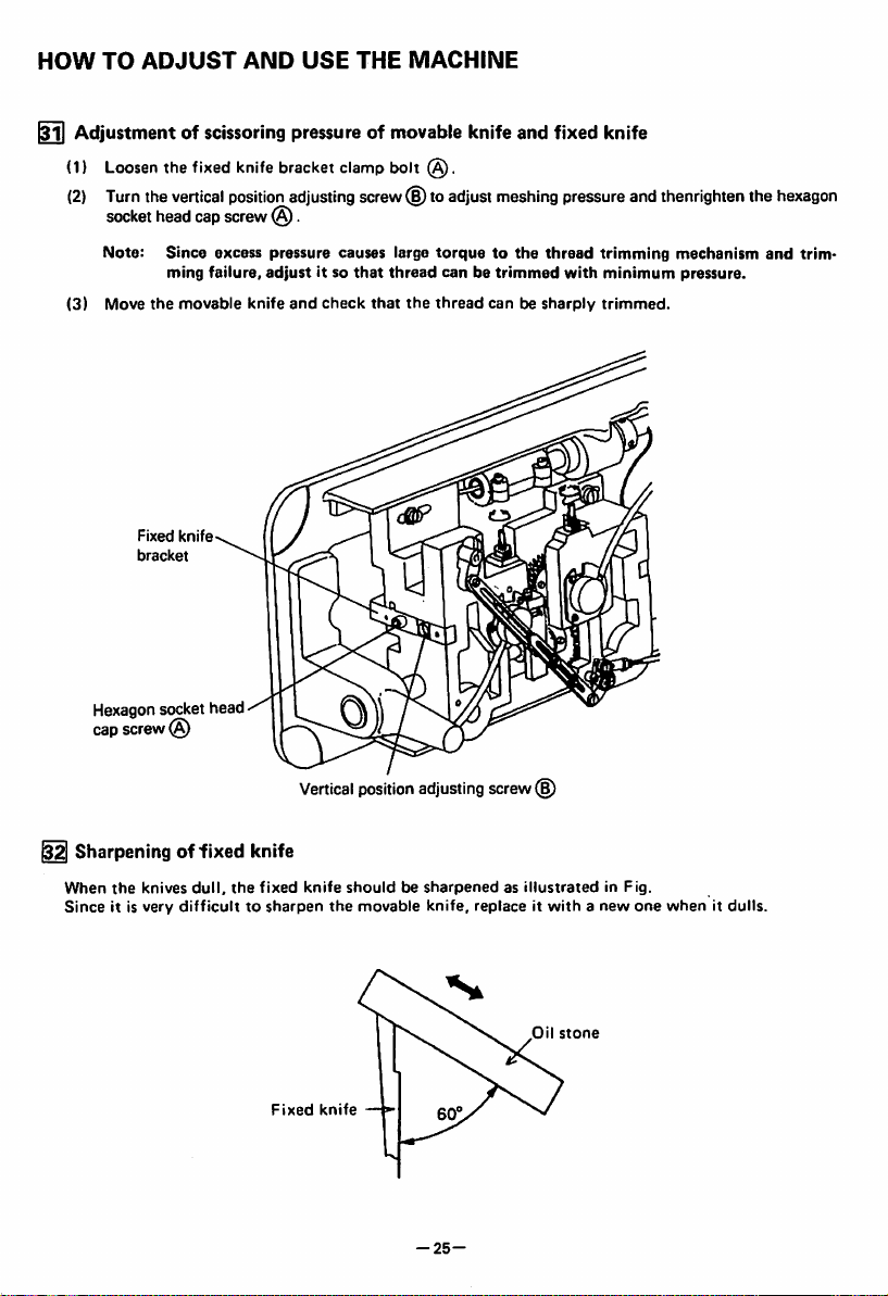
^ Adjustment of
(1)
Loosen
the
(2)
Turn
the
vertical
socket
head
Note:
Since
ming
(3)
Move
the
movable
Fixed
knife
bracket
Hexagon
cap
screw
sockethead
@
scissoring
fixed
knife
position
cap
screw
excess
failure,
bracket
(§).
pressure
adjust
knife
pressure of
clamp
adjusting
and
it so
check
screw
causes
that
movable
bolt
large
thread
that
knifeand fixed knife
(S)to
adjust
meshing
torquetothe
canbetrimmed
the
thread
canbesharply
pressure
thread
with
and
trimming
minimum
trimmed.
thenrighten
mechanism
pressure.
the
and
hexagon
trim
^
Sharpeningoffixed
When
the
knives
Since
it is
dull,
very
difficulttosharpen
the
knife
fixed
Fixed
Vertical
position
adjusting
knife
shouldbesharpenedasillustratedinFig.
the
movable
knife
-25-
screw(§)
knife,
replaceitwithanew
Oil
stone
one
whenitdulls.
Page 29

OPERATION
Adjustment forchangeofneedle-to-needle distance
(1)
Replace
thethroat
(Sincethe throat plate and feed dog are
suretouse
(2) Lean
(3)
(4)
(5)
(6)
(7)
(8)
(9)
(10)
(11) Adjustment of
the
Loosen
Remove
Loosen
hook.
When
the
Contact
link
clamp
Turn
the
Loosen
Depress
smoothly
(a) Push
machine
two
the
the
needles
the
balance
the
the
enter
the
plate,
feeddog,presser
those
specified
connecting
spring
hook
and
rocking
head
backward.
.
bracket
hooks
cranks
link
by us.)
clamp
clamp
have
(c)
and
bolt(^.
wheel by
nuts
(§)
cam
follower
the
the
cam follower crank so
hand
and
(0).
crank®and
grooveofthread
cam groove and
until
foot,
special
bolts
Q).
screws®and(Dand
been
adjusted,
(5) to
the
the
needles reach
adjust
trimmer
the
cam.
cam roller
that
the
(LU2-4730)
and
needle
the
the
pins
clamp.
adjust
spring
(§)
lowest
gap
between
@.
and
position.
rod©so
the
each
and
tighten
that
the
cam groove.
parts designed for thread trimming machine,be
install
stopper
the
connecting
cam roller enters into
(b)Turn the connecting rod (L)and adjust the clearance between the cam roller and the cam
groove
(c) Push
thread
surfaceNas
the
cam follower crank again and check
trimmer
Thread
trimmer
rocking
crank(£)
Connecting link
Hook
bracktt
smallaspossible,
cam
groove
Screw
smoothly.
^
Stopper pin ©
and
tighten
Screw
Hook
the
Cam
bracket
Spring
C0
Cam
nuts
that
roller
groove
'IW
(§)
and
(§).
the
cam roller enters into
,Cam
follower
crank
.
Thread
cam
.
Lower
i
(haft
N-phase
Cam
crank
trimmer
follower
needle
the
cam
and
connecting
roller
can
the
Bolt
Stopper
pin®
Thread
trimmer
rocktrtgcrank(Ql
-26-
!
Nut
Connecting rod I'D
NutThread
Screw
I'd!
(H
liimincr
cam
Page 30

Amitsubishi
HEAD OEFICE MITSUBISHI DENKI
BlOC
electric
MAAUNOUCHI TOKYO
corporation
100
TELEX
J2AS32
CABLE MELCOTOKYO
A180E363P02
PrintedinJapan
 Loading...