

Page 1
INDUSTRIAL
LU2-4410-4430
A
MITSUBISHI
SEWING
MACHINE
MoHaI
Classes
Thank
Please
you
for
read.this
Single-Needle,
Automatic
choosing
instruction
Mitsubishi Industrial
carefully
Variable
before
INSTRUCTION
Double-Needle
Lockstitch
Compound-Feed
undertrimmer
speed
Sewing
operating
control
Machine.
the
machine.
MANUAL
Page 2
PRECAUTIONS
[T]
Safety Precautions
1.
When
turning
around/under
2.
Power
his/her
3. The
power
the
"V" belt,
4. Avoid placing fingers, hairs,
or
motor
the
the
needle
mustbeturned
seat.
mustbeturned
adjusting
when
the
machineisoperation.
power
and
off
the
BEFORE
on,
keep
your
the
area
around
when
the
machineisnot
off before tilting
machine, or
bars
etc.,
STARTING
hands
and
the
the
when
replacing.
near
the pulley, "V" belt, bobbin
Injury
could
fingers
pulley.
used,orwhen
machine head, installing or removing
result.
OPERATION
away
from
the
operator
winder
the
area
leaves
pulley,
5. Do not insert fingers into the thread take-up cover, under/round the needle, or pulley
when
the
machine
is in
operation.
6. Ifa belt cover, finger guard, and/or eye guard are installed, do not operate the machine
without
these
safety
devices.
[2]
Precaution before Starting Operation
1. if
the
the
2. If
lubricating.
3.
Whenanew
pulley
(The pulley
4. Verify
nameplate.
machine's oil pan
machineislubricated
sewing
with
the
should
the
voltage
power
has
machine
on.
rotate
counterclockwise
and
(singleorthree)
an oil
sump,
by a
is first
drop
turned
never
oiler,
when
phase
operate
never
on,
viewed
verify
with
the
machine before filling it.
operate
the
machine
the
rotational direction of
from
the
pulley.)
those
given on
the
before
the
motor
[U Precaution for Operating Conditions
1. Avoid using
temperature(5°C or lower). Otherwise, machine failure may result.
2. Avoid
3. Avoid using the
high-frequency
using
the
machine at
the
machineindusty
machineinareas
welder
and
abnormally
conditions.
others.Isgenerated.
high temperature(35°C or higher) or low
where
too
much
electrical noise,
resulted
from
the
Page 3
-
CONTENTS
-
PREPARATION
m
Power
I 2 I
Connectionofcontrol
r3~l
Adjustment of needle bar stop position 2
CAUTIONS
m Oiling(l) 3
I 2 I
Oiling(2)
I 3 I
Oiling
FOR
OPERATION
cable
ON
connection
USE
box 2
condition 4
I 4 I Adjustment of oiling to rotating hook 4
I 5 I Cautions on operation 4
OPERATION
m Installation of needles 5
m Winding of bobbin thread 5
I 3 I Selection of
thread
I 4 I Threading of needle threads 6
m Adjustment of feed
ri"!
Setting of bobbin 7
(stitch)
length and stitch reversing (touch-back) 7
I 7 I Threading of bobbin threads 8
r"8~l
Tension adjustment of bobbin threads 8
r"9~l Balance of thread tension 8
I101 Needle thread tension 8
rm
112I
nn
Adjustment
Timing
Adjustment
of presser foot pressure 8
between
rotating
hook
motion
and
needle
motion
of feed dog height 10
1141 Relationship between rotating hook motion and take-up lever motion 11
115 I Relationship between hook motion and opener motion 11
I161
Relationship
between needle motion and feed dog motion 12
117I Safety clutch device 13
1181 Upper feed adjustment (needle side) 14
I19 I Outside presser foot and inside presser vertical stroke adjustment 14
riol
Adjustment of forward/backward stitch length 15
rm
Installation of movable knife 15
Adjustment
Adjustmentofneedle
I
241
Adjustment
I25I
Sharpeningoffixed
I
261
Adjustment
of thread
trimmer
threads
cam 16
tension
of scissoring pressure of
knife
for change of
needletoneedle
release
assembly
movable
knife
and
fixed
knife
distance 19
17
18
18
1
3
6
9
ADJUSTMENT
I 1 I "1—2 POSITION" select switch operation
i 2 I Pedal operation
AND
OPERATION
OF
CONTROL
UNIT
20
20
I 3 I Adjusting the pedaling forces 20
I 4 I Adjusting the stitching speed 21
I 5 I Optional functions 22
Specifications 24
Page 4
PREPARATION
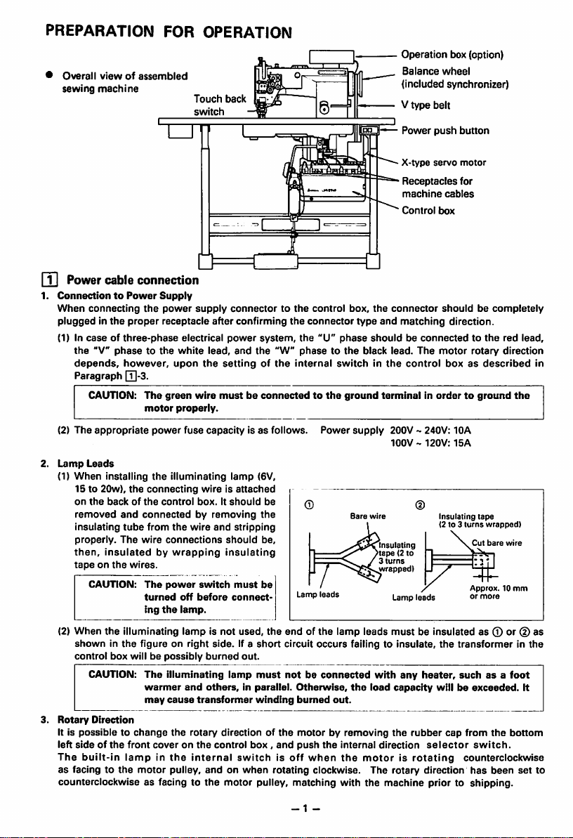
Overall
viewofassembled
sewing
machine
FOR
m Power cable connection
1.
ConnectiontoPower
When
connecting
pluggedinthe
(1) In
caseofthree-phase
the
"V"
phasetothe
depends,
Paragraph [T|-3.
CAUTION:
(2)
The
appropriate
Lamp
Leads
(1)
When
installing
15 to
20w),
on
the
backofthe
removed
insulating
properly.
then.
Insulatedbywrapping
tapeonthe
CAUTION:
(2)
When
the
showninthe
control
box
CAUTION:
Rotary
Direction
It is
possibletochange
left
sideofthe
The
built-in
as
facing to
counterclockwise
Supply
the
power
proper
receptacle
electrical
white
however,
the
and
tube
The
wires.
illuminating
upon
The
green
motor
properly.
power
fuse
the
illuminating
connecting
control
connectedbyremoving
from
the
wire
connections
The
power
turned
off
ing
the
lamp.
lampisnot
figureonright
willbepossibly
The
illuminating
warmer
and
may
cause
the
front
coveronthe
lampinthe
the
motor
pulley,
as facing to
OPERATION
Touch
back
switch
supply
connectortothe
after
confirming
power
lead,
the
wire
capacityisas
wireIsattached
box.Itshould
wire
and
switch
before
side.
burned
others,inparallel.
transformer
rotary
control
internal
andonwhen
the
system,
and
the
settingofthe
mustbeconnectedtothe
lamp
(GV,
be
the
stripping
should
be,
insulating
must
be
connect
used,
the
If a
short
out.
lamp
must
winding
directionofthe
box,
switchisoff
motor
pulley,
control
the
connector
the
"W"
"U"
phasetothe
internal
follows.
Lamp
Power
leads
endofthe
circuit
occurs
notbeconnected
Otherwise,
burned
motorbyremoving
and
push
the
when
rotating
clockwise. The
matching
Operation box (option}
Balance
(included
V
Power
X-type
Receptacles
machine
Control
box,
the
connector
type
and
matching
phase
shouldbeconnectedtothe
black
switchinthe
ground
lamp
lead.
control
terminalinordertoground
supply
200V
100V
Bare
wire
Insulating
tape<2to
3
turns
wrapped)
Lamp
leads
must
failing to
the
with
load
insulate,
any
capacity
out.
the
internal
direction
the
motorisrotating
rotary
with
the
machine
wheel
synchronizer)
type
belt
push
button
servo
motor
for
cables
box
shouldbecompletely
direction.
red
The
motor
rotary
direction
boxasdescribed
the
240V:
10A
120V:15A
@
Insulating
tape
(2to3
turns
wrapped)
Cut
bare
wire
Approx.10mm
or
leads
more
be insulated as 0 or (D as
the
transformerinthe
heater,
suchasa
foot
willbeexceeded.
rubber
cap
from
the
selector
bottom
switch.
counterclockwise
direction
prior to
has
been
shipping.
lead,
set
in
It
to
- 1 -
Page 5
PREPARATION
FOR
OPERATION
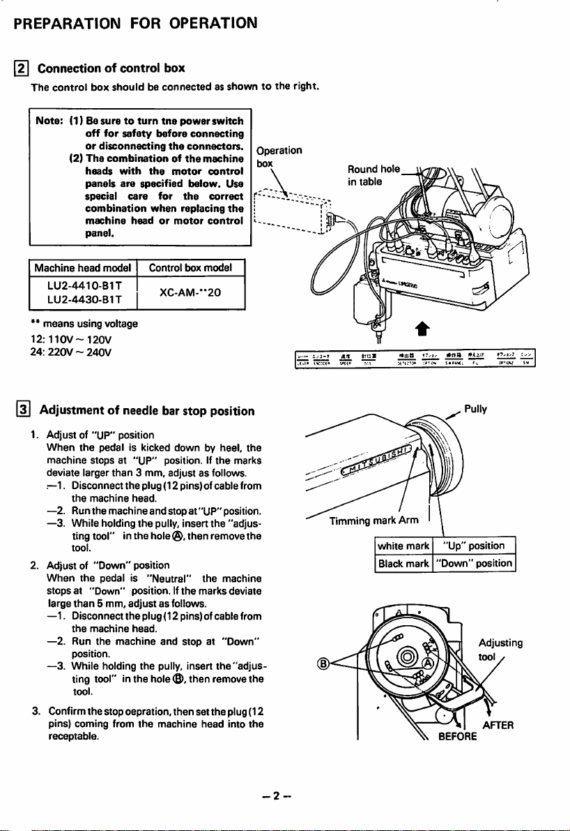
Connection
The
control
Note:
Machine
LU2-4410-BIT
LU2-4430-B1T
•*
means
12:110V~120V
24:
220V~240V
of
box
shouldbeconnectedasshowntothe
(1) Be
suretoturn
off
for
or
disconnecting
(2)
The
combinationofthe
heads
panels
special
combination
machine
panel.
head
model
using voltage
control
tne
safety
before
with
the
are
specified
care
for
when
headormotor
Control
XC-AM--20
box
the
Adjustmentofneedle bar
1. Adjust of "UP" position
When
the
pedal
machine
deviate larger
.—1.
Disconnect
the
—2. Run
—3. While holding
ting tool" in
tool.
2. Adjust of "Down" position
When
the
stopsat"Down"
large
than
Disconnect
—1.
the
—2. Run
position.
—3.
While
ting tool" in the hole0,then remove the
tool.
3. Confirm the stop oepration,
pins)
coming
receptable.
is kicked
stopsat"UP"
than
3 mm, adjustasfollows.
the
machine
the
pedalis"Neutral"
5 mm,
machine
the
plug (12 pins) of
head.
machine
the
the
position.Ifthe
adjustasfollows.
the
plug (12 pins) of
head.
machine
holding
the
from
the
and
pully, insert
hole®,
position. If
stopat"UP"
and
pully,
machine
power
switch
connecting
connectors.
machine
motor
control
below.
box
Use
correct
the
control
model
position
by heel,
the
the
replacing
stop
down
cable
position.
the
"adjus
then remove the
the
machine
marks
cable
stopat"Down"
insert
the
then
set
the
plug(12
head
into
the
marks
from
deviate
from
"adjus
the
Operation
box
right.
Timming mark Arm
Round
in
table
hole
white
Black
mark
mark
"Up"
"Down"
Pully
position
position
Adjusting
tool
AFTER
-2
-
Page 6
CAUTIONS
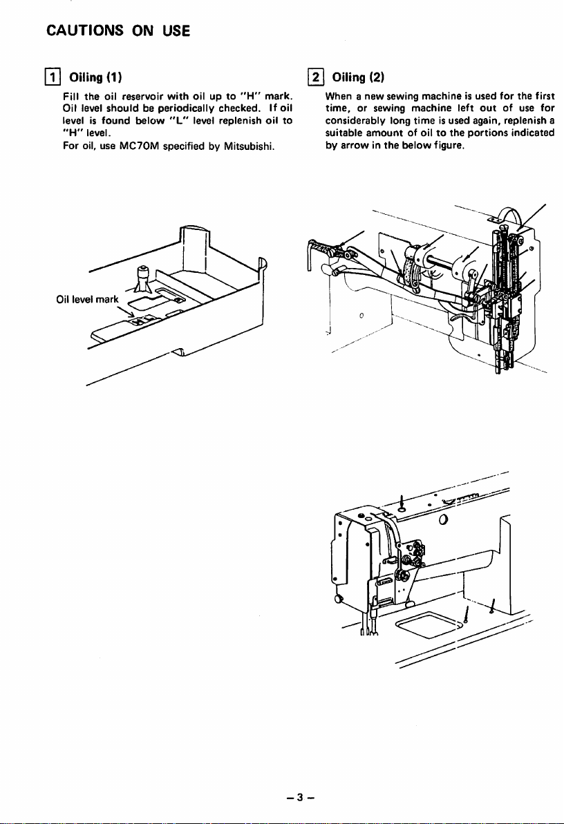
\T\
oiling
Fill
the
Oil level
level is
"H"
level.
For oil, use
Oil
level
ON
USE
(1)
oil
reservoir
shouldbeperiodically
found
MC70M
with
oilupto
below
"L"
level
specified by Mitsubishi.
"H"
checked.
replenish
mark.
If oil
oil
to
[2]
Oiling
Whenanew
time,
considerably
suitable
by
(2)
sewing
or sewing
long
amountofoiltothe
arrowinthe
machineisused
machine
timeisused
below
figure.
left
again,
portions
out
for
the
of use for
replenish
indicated
first
a
-3
-
Page 7
CAUTIONS
ON
USE
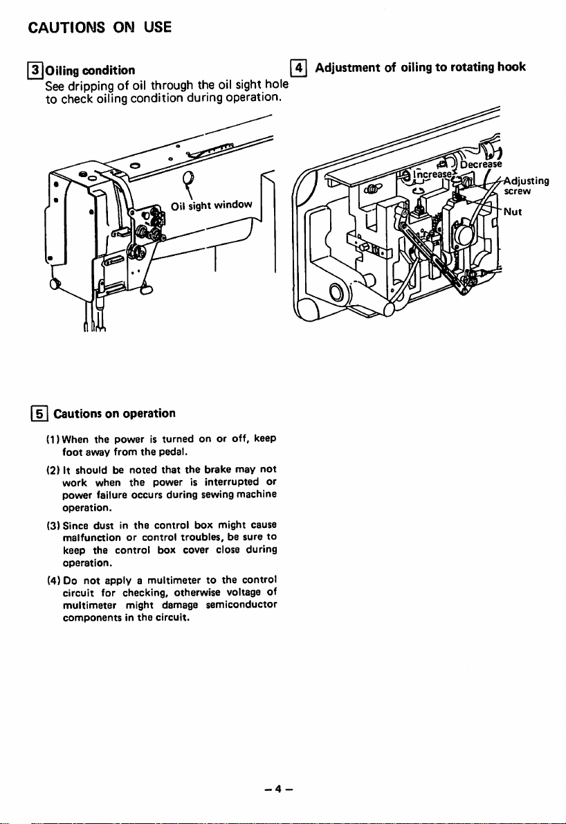
I^Oiling
condition
Seedrippingof oil through the oil sight hole
to check oiling condition during operation.
Oil sight window
j
Cautionsonoperation
11)
When
the
foot
(2)Itshouldbenoted
work
power
operation.
(3)
Since
malfunctionorcontrol
keep
operation.
(4) Do
poweristurnedonor
away
from
the
pedal.
that
when
the
failure
occurs
dustinthe
the
control
not
applyamultimetertothe
the
powerisinterrupted
during sewing
control
troubles,besure
box
cover close
circuit for checking, otherwise voltage of
multimeter
componentsinthe
might
damage
circuit.
off,
brake
may
machine
box
might
semiconductor
keep
not
or
cause
during
control
0
Adjustmentofoilingtorotating
to
hook
Decrease
"°"i ' ' *
djusting
screw
Nut
-4
-
Page 8
OPERATION
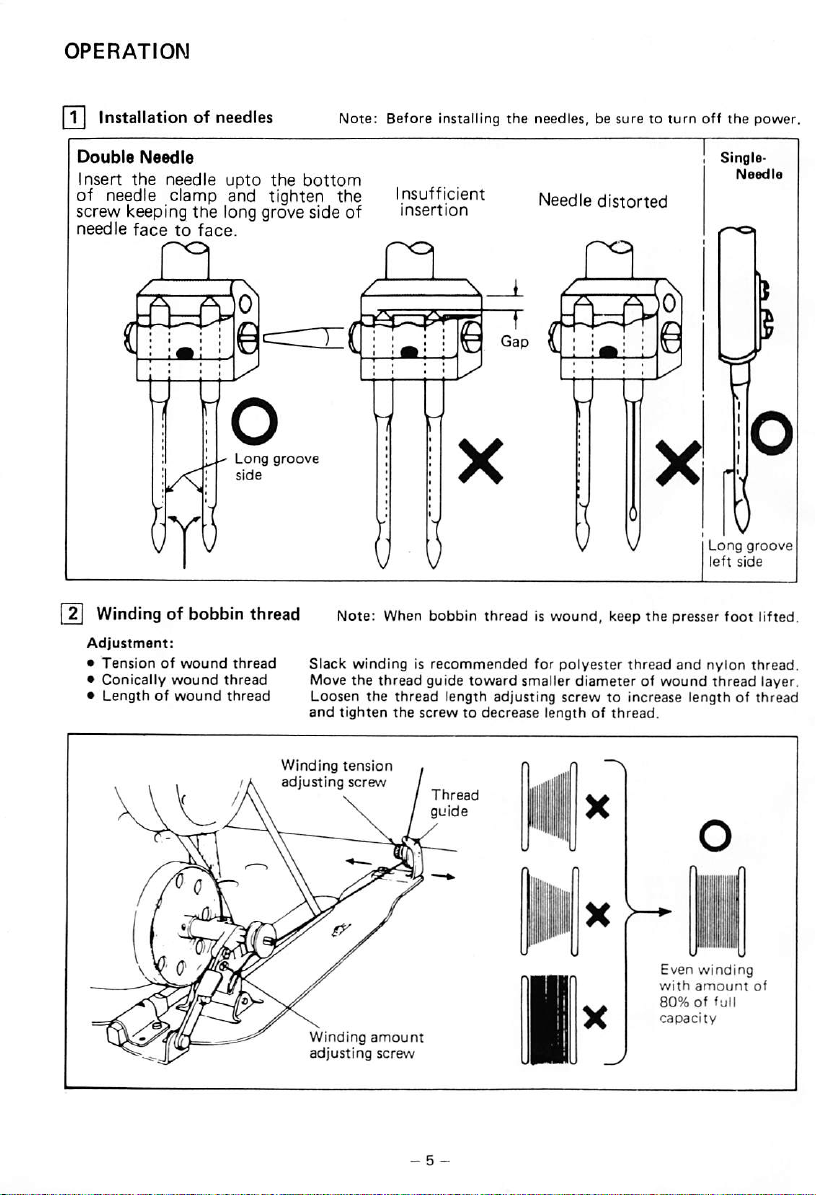
[T]
Installationofneedles
Note:
Before
installing
the
needles,besuretoturn
off
the
power.
Double
Insert
of needle clamp and tighten
screw keeping
needle
Needle
the
needle
the
facetoface.
I
Windingofbobbin
Adjustment:
•
Tensionofwound
• Conically
• Length
of
wound
wound
upto
the
bottom
long grove side of
Long
groove
side
thread
thread
thread
thread
the
Note:
Slack
Move
Loosen the
and
tighten
nsufficient
insertion
When
windingisrecommended
the
thread
thread
the
Needle
distorted
bobbin
threadiswound,
guide
toward
length adjusting screw to increase length of
screwtodecrease
for
smaller
lengthofthread.
keep
the
polyester
thread
diameterofwound
presser
and
Single-
Long
left
foot
nylon
thread
Needle
groove
side
thread.
lifted.
layer.
thread
i
/A
Winding
adjusting
I
tension
screw
Thread
guide
Even
winding
with
amount
80%offull
capacity
of
Page 9
OPERATION
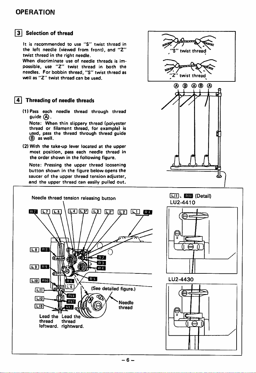
[y|
Selection of thread
Itisrecommended
the
left
twist
When
possible,
needles.
wellas"Z"
[41
(1)Pass
needle
threadinthe
discriminate
use
For
Threadingofneedle
each needle
guide
(§).
Note:
When
threadorfilament
used,
pass
(§) as well.
(2)
With
the
most
position,
the
order
Note:
Pressing
button
showninthe
saucerofthe
and
the
Needle
to
use
(viewed
from
right
needle.
useofneedle
"Z"
twist
bobbin
thread
thread,
canbeused.
twist
threads
thread
thin
slippery
the
take-up
showninthe
upper
thread
thread,
thread
through
lever
pass
each
the
upper
figure
upper
thread
thread
can
tension releasing button
"S"
twist
front),
threadsisim
thread
in
"S"
twist
through
thread
for
example)
thread
locatedatthe
needle
following
thread
below
tension
easily
figure.
pulled
thread
and
"Z"
both
the
thread
thread
(polyester
guide
upper
thread
loosening
opens
the
adjuster,
out.
in
"S"
twist
thread
as
"Z"
® ®
twist
thread
®(D
®
V
is
in
L
Iliik
I3D
LU2-4410
bil
(Detail)
Lead
the
thread
leftward,
Lead
the
thread
rightward.
(See detailed figure.)
Needle
thread
-6-
LU2-4430
<k
Page 10
OPERATION
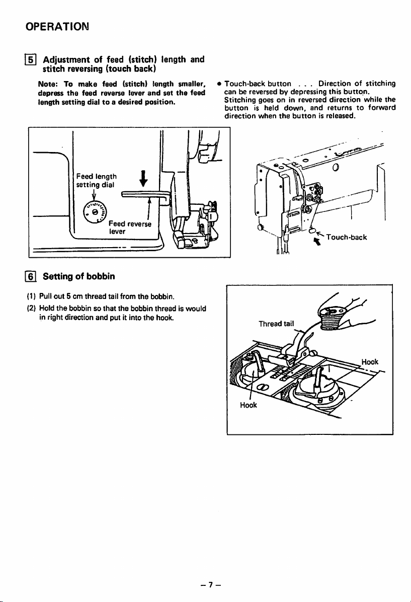
I
Adjustmentoffeed
stitch
reversing (touch back)
Note:
To
the
setting
make
feed
Feed
setting
depress
length
Settingofbobbin
(1) Pull
out5cm
(2) Hold
the
bobbinsothat
in right direction
reverse
dialtoa
length
thread
and
feed
dial
Feed
lever
tail
put it into
(stitch)
(stitch)
lever
desired
reverse
from
the
bobbin
length
length
and
position.
I
•
the
bobbin.
threadiswould
the
hook.
set
and
smaller,
the
feed
•
Touch-back
canbereversedbydepressing
Stitching
buttonisheld
direction
button
goesonin
down,
when
the
Thread
tail
. . .
reversed
buttonisreleased.
Directionofstitching
this
button.
direction
and
returnstoforward
Touch-back
while
the
- 7 -
Page 11

OPERATION
[7]
Threadingofbobbin
(1) Put the hook into the bobbin case and press
down
the
leftonthe
(2) While holding
hand,
hand.
showninthe
lifted.
needle
ward.
latch
bed.
Thread
the
rotate
the
By
pullingupthe
figure,
Each
combinationofbobbin
thread
should
threads
.
The
thread
end
should
Thread
Opener
two needle threads by left
handwheel
the
bobbin
be aligned
one
needle
turn
threads,
threads
thread
and
by right
will
led
and
back
be
(Tol
*
Needle
referencetobobbin
as
• To
be
sion
Needle
special
and
spring.
Balanceofthread
AO
8X
CX
Needle
threadtension
thread
tension
adjust
needle
adjusting
thread
fabric
movable
thread
nut.
tension can be also
and
range of slack
tension
Balanced
Tight
bobbin
Loose
bobbin
shouldbeadjusted
thread
threadbychanging
needleorloose
tension
needleortight
tension
tension.
tension,
thread
tension
turn
adjusted
each
ten
for
intensity
adjusting
in
[si
Tension
Tension
screw
adjusmtnetofbobbin
adjusting
threads
Loosen
Tighten
l\lfe
Loosen
&
|Tl|
Adjustmentofpresser
Pressuretofabric(s) can be
pressure
-8-
adjusting
screw.
Tighten
1
Thread
adjusting
foot
pressure
adjustedbyturning
Weak
Pressure
adjusting
screw
tension
nut
the
Page 12

OPERATION
12 Timing between rotating hook motion
and
needle
motion
(1) Set feed length (stitch length) to
feed
setting
(2) When
dead
dial.
needleislifted
point,
as shown in Figure, the follow
2.4mm
ing positional relationship should be main
tained.
—The
upper edge of needle eye should be
2.3mm
below
the
hook
—The hook point should be located at the
centerofneedle
—Gap
between the hook point and the side
faceofneedle
axis.
shouldbe0.05mm.
(3) Needle/rotating hook position can be ad
justedasfollows.
(For easy adjustment, it is recommended
that
the presser foot,
throat
dog assemblies are removed.)
•
Positioningofhook
(1)
When
the
smaller
side
and
crossed
left
larger wheel so
former
gear
thatofthe
(2)
Tighten
for
(3)
Approximate
"C"
the
position.
•Tofinely
motion
each
set
screw,onthe
screwofhook
needle
adjust
and
screwoflarger
wheel
in its
from1mmto2mm.
point
needleisat
herical
side
shouldbeengaged
that
the
comesonthe
latter
gearonthe
"S"
screw,
hook
positionofhook
shouldbefound
when
the
timing
hook
motion,
gear
wheel
axial
direction
DOWN
needleisat
between
"6"
on the
from
the
lower
point.
plate and feed
position,
gearsonthe
"S"
whereispunched
shaft.
and
with
screwofthe
front
side,
reverse
side.
close
DOWN
the
move
needle
the
the
loosen
withinarange
the
right
the
and
set
gear
Gap
between
and
upper
Needle
2.4mm from ^
needle lower ^
dead
point
Center
needle
hook
edgeofneedle
2.3mm
lift:
"An
of
axis'
Hook
point
eye
0.05mm
point
) ^
to
1 ~
2mm
1 ~
2mm
Needle
DOWN
position
-9
-
Page 13

OPERATION
13
Adjustmentoffeed
Height of feed dog and pressure of presser
shouldbeadjusted
following
♦
Fabric
too
♦
Even
dogistoo
small.
♦
Feed
point
cautions:
will be
high, or
stitch
damagedifthe
pressureofpresser
length
loworpressureofpresser
dog
height
where
the
dog
height
for
Individual
fabricis)
feed dog
with
extends
footistoo
cannotbeassuredifthe
footistoo
shouldbemeasuredatthe
needleisat
the
top
position.
foot
the
large.
feed
[0.8mm
1.0mm
For
light
fabrics
For
usual
fabrics
For
heavy
fabrics
Adjustment
(1)
Lean
(2)
Turn
the
(3)
Loosen
procedure
the
machine
the
handwheelbyhand
feed
dog
the
feed
(4) Vertically move
tion
indicatedbyarrowinthe
adjustitto
(5)
After
set
The
1.2
mm.
feed
screw.
the
adjustment,
dog
adequate
Approx.
throat
.
Approx.
throat
.
Approx.
throat
head
risestothe
bar
set
the
feed bar (in
plate
plate
plate
backward.
and
maximum
screw.
0.8mm
1.0mm
1.2mm
stop
height.
the
figure)
height.
tighten
the
feed
heightisfactory-adjusted
from
from
from
when-
direc
bar
1.2mm
zsn
to
Set
Feed
screw
bar
to
-
10
Page 14

OPERATION
14| Relationship between rotating
motion
When
moved
relationship
take-up
follows:
(1)Turn
(2)
(3) If
I
opener
and
take-up
the
timing
for
lever
the
take-up
Lean
the
sure
the
timing
the
bossoflower
the
black
line,
stallitagaintoadjust.
Relationship
belt
its
replacement,
between
motion
balance,
leverisliftedtoits
machine
arrow
belt
is in
timing
markisnotinline
remove
between
motion
lever
(toothed
rotating
should
wheel
head
(timing
line
shaft
the
backward
with
hook
motion
for
hook
be
and
upper
mark)
the
bearing.
timing
belt) was re
example,
motion
adjusted
stop
dead
putonthe
black
belt
motion
when
and
with
hook
point.
make
line
and
the
and
as
the
on
the
in
and
Black
lower
lineonboss
shaft
bearing
of
Timing
Timing
''^Timing
belt
sprocket
belt
mark
(1)Turn
when
remotely
(2)
Make
holder
0.2mm.
(3) If
opener
tionofthe
the
the
sure
the
balance
opener
from
gap
and
gapistoo
holder
opener.
wheelbyhand
holderislocated
the
throat
plate.
between
the
set
the
openerisapproximately
large or
screw
small,
(§) and
and
bobbin
loosen
adjust
stop
most
case
posi
the
-11-
Approx.
0.2mm
Opener Screw®
Opener
holder
Page 15

OPERATION
Relationship between needle
and
feed
dog
motion
(1)Set feed length to
dial.
(2)
Lean
the
machine
"0"
on the feed setting
head
backward.
motion
(3) Loosen the feed lifting rock shaft crank set
screws
(§) and (§) .
(4) Set the needle at the lowest position.
(5) Adjust
vibration
the
distance between presser rod
prevention
rod
to
9mm
and
and
temporarily tighten the feed lifting rock
shaft
crank
set
screws@and
(§) .
(6j Check that the right feed lifting rock shaft
crank is connected with the link at right
(71
angle, as
If the
move
move
shown
connection
the
back
the
right link to
in Figure.
is not at
cover,
connect
loosen
right
screw
the
angle,
@ and
right feed
re
lifting rock shaft with the link at right angle.
(8)After the completion of adjustment, fully
tighten
the
screws
@ , (§) and © .
At
this
time
make
certain
that
needle
enter
of
the
the
hole.
feed
dog
needle
holeatthe
can
center
Screw
Screw
(g)
Feed
shaft
lifting
crank
rock
(middle)
.Feed
shaft
lifting
crank
rock
(right)
Link
9mm
Needle
—Vibration
prevention
rod
rod
Feed
shaft
-12-
lifting
crank
rock
(right)
Screw©
kvx
Screw©
J
•aij.
Page 16

OPERATION
(ITI
1)
FUNCTION
safety
Safety
the
the
machine is
ation.
clutch
clutch
hook
threadiscaught
device is installed to
and
cog
loaded
OF
SAFETY
DEVICE:
belt
from
into
the
abnormally
damage in case
hook
during
CLUTCH.
1) When the safety clutch acts, the cog belt
pulley
will be
hook
rotate.
shaft will
Stop
unloaded,
stop.
the
then
the
arm
rotation
shaft
The
operationofmachine.
2) Clean the thread thoroughly which iscaught
into
the
hook.
3) Turn the cog belt hub by hand, and check
whether
properly,
the
place
hook
the
shaft
rotates
clutch
deviceasfollows.
lightly
prevent
when
oper
only will
and
the
Safety
clutch
belt
pulley
belt
hub
of
Balance
wheel
2) HOW TO
1) While pressing
opposite
balance wheel slowly by right
from
SET
THE
SAFETY
down
sideofbedbyleft
youasshowninthe
the
push
buttononthe
hand,
figure.
hand
2) The balance wheel will stop by the gear
plate,
but
turn
the
firmly.
3) Release
the
push
balance
button.
wheel
4) As shown in the Figure, the safety clutch
deviceisset.
3)
FORCE
CLUTCH.
1)
2) To adjust
3)
The
smallest
tric
The
white
loosen
pin.
After
the
APPLIED
force
when
pin
faces
force
mark
the
the
set
screw.
TO
THE
appliedtothe
the
the
proportionally
faces
the
force, slide the timing belt,
set
screw,
adjustment,
safety
white
markofthe
centerofthe
the
outside.
and
make
increasesasthe
turn
clutch is
the
suretofasten
SEFETY
lower
CLUTCH.
turn
the
away
more
the
eccen
shaft.
eccentric
White
Mark
Strengthen
Eccentric
I-—
Push
button
Gear
Timing
Pin
Screw
plate
Belt
-13-
Weaken
Lower
Shaft
Eccentric
Pin
Page 17

OPERATION
1}
UPPER FEED ADJUSTMENT
(NEEDLE
If
the
to
the
horizontal feed
the
upper
(Howtoadjust)
1) Loosen
2) Move the special bolt upward to decrease
upper
3) Move
the
upper
lower feed theoretically becomes equal
the
reference
shaft
4) Securely tighten the special bolt after adjust
ment.
SIDE)
uneven feeding occurs according to
fabric,
adjust
the
long hole of
crank
(right)toadjust
bolt.
downwardtoincrease
upper
feed
and
horizontal
feed.
the
crank.
the
feed
special
special
feed.
shaft
length.
bolt
The
lineonthe
the
the
feed
Push
mating
button
notch
Horizontal
Reference//^^~Upper
shaft
crank,
feed
right
decreases
v<;;^line
^
Link
(Needle
Special-..-^
bolt-Upper
feed
-/•
increases
at
rock
bar
link)
h9| Outside
vertical
When
when
stroke
shouldbeadjustedasfollows:
presser
stroke
fabric
thicknessoffabric
(movable range) of
Adjustment
1)
Loosen
the
special
2) Teh vertical
come
maximum
upward
and
set.
3)
The
vertical
when
the
nutismoved
4) After
•
special
The
be
adjusted
mm.
the
bolt.
vertical
adjustment,
withinarange
foot and
adjustment
with
large
elasticityissewn,
changes,
bolt.
strokesofthe
when
the
strokes
strokesofthe
becomes
inside
presser
the
the
vertical
presser feet
presser feet be
crank
rodismoved
downward
minimum
and
fully tighten the
presser
feet
from6mm
set.
can
to 2
or
Special
bolt
Crank
-Increase
Decrease
Crank
rod
-14-
Page 18

OPERATION
Adjsutmentofforward/backward
20
stitch
length
Forward/backward
by
moving
figure,asfollows:
(1)
Remove
(2)
Set
the
Position
feed
adjusting
stitch
length
length
(3)
Loosen
(One
screw
iver
passed
openedbyremoving
(4)Toincrease
eccentric
To
increase
eccentric
21
Installationofmovable
1.
Initial
positionofmovable
(1) Turn
the
stitch
length
the
eccentric
the
arm
stitch
and
regulatar
two
back
length
make
surenoplay
cam
(If play exists,
adjusting
screw
screwsoffeed
shouldbeloosenedbyscrewdr
through
forward
shaft
counterclock-wise.
backward
shaft
clock-wise.
canbeadjusted
shaft
cover.
adjustment
dial
and
again.)
the
hole
rod
and
stitch
length,
stitch
length,
showninthe
dialto"0"
existsinthe
adjust
the
stitch
adjusting
rubber
that
cam.
can
plug.)
turn
turn
the
be
the
the
knife
knife
balance wheel and lower the needle bar to
To
backward i|^
stitch length
Eccentric
shaft
Connecting
the
lowest position.
lessen
rod
To
lessen
forward
stitch
Screw
' I
length
(2)Pushthe cam followercrank so that the cam roller enters into the thread trimmer cam groove.
(3)Turn the balance wheel until the black mark point on the arm meets the white mark point on the
balance
wheel.
Set the cam follower crank at this position with a screwdriver temporarily preventing
roller
coming
out
from
the
cam
groove.
(4)
Loosen
the
thread
(5) Adjust
the
fixed
trimmer
the
movable knife so
knife,asshowninFigure
rocking
crank
clamp
bolts
@ and(^.
that
the movable knife end slant portion protrudes 0 —0.5 mm from
and
tighten
the
bolts
@ and .
the
cam
Bolt@
Thread
rocking
Thread
rocking
trimmer
crank
trimmer
crank
Bolt(B)
-15-
0.5mm
Movable
knife
Fixed
knife
Page 19

OPERATION
2.
Gap
between
holder
(1)
Turn
reaches
(2)
With
press
wheel
extremityofits
stopper
the
the
cam
until
movable
balance
the
lowest
needleatthe
follower
the
stroke.
knife
wheelbyhand
position.
lowest
crank,
movable
knife
(3) Manually rotate the inner hook in
tion
indicated by
arrow
in Figure
gap between the movable knife and the in
ner hook stopper to about 0.5 mm (the
^
Adjustment
(1)
(2)
(3)
screws
for
@
and
this adjustment).
of thread
Turn
the
balance wheel by
Maintaining
grooveofthread
Turning
starts
pointonthe
To
adjust,
the
the
moving
loosen
(@)
needle
trimmer
balance
when
arm.
shouldbeloosened
trimmer
position,
wheel by
the
green
two
thread
and
turn
hand
cam.
bobbin
until
position,
the
balance
reaches
the
and
cam
until
depress
hand,
mark
trimmer
case
needle
de*
the
direc-
adjust
the
needles reach
the
cam
adjust
the
pointonthe
cam
clamp
Movable
knife-
Hook positioner
Approx.
0.2
mm
the
lowest position.
follower
thread
crank
trimmer
and
put
the
camsothat
cam
the
balance wheel comes in line with
screws
@ .
Screw
Screw
Inner
roller
movable
the
black
hook
into
the
knife
mark
Cam
groove
Thread
^
Screw
trimmer
Cam
crank
Cam
follower
roller
@
cam
-16-
Green
mark
Black
point
point
mark
Balance
wheel
Page 20

OPERATION
2^
Adjustmentofneedle
threads
tension
release
assembly
(1) Turn the balance
(2)
Maintaining
grooveofthread
(3) Turning the balance wheel by hand, adjust the thread tension releasecam so that the tension disc
close
when
on
the
arm.
To
adjust,
(4)
Opening
the convexed portion of thread release cam, as shown in Fig.
To adjust, loosen the screws (g) and draw the wire.
(5)
Make
fine
(6)
Loosen
the
Thread
tension
release
lever
Screw(M
Roller
(g)
Thread
release
cam
Thread
trimmer
cam
wheel
by hand until the needlesreach the lowestposition.
the
needle
position,
trimmer
the
white
loosen
degreeoftension
two
cam.
mark
tension
pointon the
release
disc
adjustmentbyloosening
nut
(5)
and
make
(D
Screw
©
depress
the cam follower crank and put the cam rollerinto the
balance
cam
clamp
shouldbeadjusted
thenut{§),
the
outer
casing
approach
Cam
follower
crank
Cam
roller
Outer
wheel
screws
with
Arm
comesinline
@.
the
tension
release
rightwardtoincrease
White
Black
point
casing
withthe
roller
mark
point
mark
black
(g)
the
Balance
mark
mounted
opening
point
on
value.
wheel
-17-
Page 21

OPERATION
24] Adjustmentof
(1)
Loosen
(2)
Turn
socket
Note: Since excess pressure causes large
(3) Move
Fixed
bracket
Hexagonsocket head
cap
screw
scissoring
the
fixed
knife
bracket
the
vertical
head
the
position
cap
screw
@.
ming failure, adjust it so
movable knife
knife
@
pressure of
clamp
adjusting
and
screw
that
check
movable
knifeandfixed knife
bolt (§).
(§)to
adjust
meshing
torque
thread can be trimmed with minimum pressure.
that
the
to the thread trimming mechanism and trim
thread
can be sharply trimmed.
pressure
and
thenrighten
the
hexagon
25
Sharpeningoffixed
When
the
it is
knives
very
Since
Vertical
knife
dull,
the
difficulttosharpen
fixed
Fixed
position
adjusting
knife
shouldbesharpenedasillustrated
the
movable
knife
-18-
screw
knife,
replaceitwithanew
Oil
(§)
stone
in Fig.
one
whenitdulls.
Page 22

OPERATION
26 Adjustment fot
changeofneedle-to-needle
distance
(LU2-4430)
(1) Replace the throat plate, feed dog and needle clamp.
(Sincethe throat plate and feed dog are special parts
suretouse
(2) Lean
(3)
Loosen
(4)
Remove
(5)
Loosen
hook.
(6) When
(7)
Contact
link
(8)
Turn
(9)
Loosen
(10)
Depress
smoothly
(11) Adjustment of the cam groove and the cam roller
(a) Push
those
specified by us.)
the
machine
two
the
the
the
the
clamp
the
balance wheel by
the
the
the
head
connecting
spring
hook
bracket
needles
and
rocking
bolt(^.
nuts
(§)
cam
follower
enter
the
grooveofthread
cam follower crank so
backward.
link
clamp
.
clamp
hooks
have been
cranks@and
hand
until
and
(§).
crank
(E)
bolts(j).
screws
adjusted,
(§)tothe
the
and
trimmer
that
(§)
needles reach
adjust
cam.
the cam roller enters into
and
(§)
install
stopper
the
designed
and
adjust
the
spring
pins
(1)
the
lowest
connecting
for thread trimmingmachine, be
gap
between
and
and
tighten
position.
rod(Qso
that
the
cam groove.
(b)Turn the connecting rod (L)and adjust the clearance between the cam roller and the cam
groove
surface
N as
smallaspossible,
and
tighten
the
nuts
(g)
and
(H)
.
(c) Push the cam follower crank again and check that the cam roller enters into the
thread
trimmer
Thread
rocking
Connecting link
Hook
trimmer
crank
bracket
cam
©
groove
Screw
smoothly.
6$
Stopper
pin©
Screw
Hook
Cam
@
bracket
Spring'
Cam
roller
groove
w
N-phase
,C3in
crank
.
Thread
cam
follower
.
Lower
1Shalt
Cam
crank (1^
Cam
each
the
trimmer
follower
roller
the
cam
needle
roller
and
connecting
can
Bolt
(XI
Stopper
Thread
pin©
\ \
trimmer
rocking crank {jjl
-19-
Nut 'H '.QT
Connectirtgrod^'Lj
^ut
>5)
Thread
t.immor
cam
Page 23

ADJUSTMENT
AND
OPERATION
OF
CONTROL
UNIT
Setting
Thestop
-5 2-
the
position
mark
mark
1-2
ofthe
When the switch is set to 1
and
trim
the
thread.
I2 I
Pedal
Operation
The
two-step
go
up.
\^Pedal
12
POSITION
Pedal
1
POSITION
2
POSITION
operation
pedal
Position
Settin^\
POSITION
sewing
2
POSITION
1
POSITION
heeling
Switch
machine
POSITION,
mechanism
Toe
Stopatneedle
UP position
Stopatneedle
DOWN position
down
Neutral
fully
allows
canbe
determined
bytheselect
switch
onthe
panel.
heelingthe pedalcauses the sewing machineto rotateoneturn
the
thread
tobe
trimmed
—
Neutral
Presser
goes
Presser
goes
up.
up.
—
foot
foot
Light Heeling
andthe
presser
foottoautomatically
Neutral —Full Heeling
Sewing
machine
and
trims
goes
up.
Sewing
machine
from DOWN to UP position
trims
thread,
goes
up.
thread,
then
rotates
then
rotates
presser
presser
/ //'
Neutral (stitching
start)
^^•^I^Heeiing
Neutral
one
half
turn
foot
turn
and
foot
Note: 1. Thestitching speed can be variedby changing the pedal toeing degree.
I3 I
Adjusting
Pressures
The lever unit spring
stepsbychanging
ponding
spring
For automatic
the
pressure
Pedal
pressure
the
adjust
presser
Toeing
is adjustable in
position of
knob.
fool lifting,
and
Heeling
the
use
three
corres
the
optional LE-FAlifter or a
Heeling
adjust
Toeing
adjust
spring
knob
spring
knob
solenoid
pressure
pressure
valve (24V DC).
| It
H
Page 24

ADJUSTMENT
I 4 I
Adjusting
AND
the
Operating
OPERATION
Speeds
OF
CONTROL
UNIT
1 Adjusting
Two variable resistors are available for adjustment ofthe maximum speed;
and
low
Is
To
2. Adjusting
The low
and
to
Speed
the
maximum
the
other
speed
factory-setasfollows:
settoany
CAUTION
The
motor
counterclockwise
250spm).
rt
on the control box panel. The external variable resistor (knob) allows
and
the
maximum
Internal
Variable
speed
speed
setbythe
pulley is used.
the
low
speed
speed
Is adjustable with
setting
Internal variable
L P T H M
iwii^iwiraiw
speed
2000spm
outside
internal
(speed
turn
(speed available with the pedal fully toed)
speed
set by the Internal variable resistor H. The internal variable resistor H
ResistorHSetting
the
above
range,
adjust
the
Internal variable
variable
available
the
decreases.
resistors
resistorHand
with
the
internal variable resistor L.Clockwise
The
speed
external
pedal slightly toed)
Is adjustable
one
Islocated In
adjustment
External Knob Adjustable
Low
speedtomaximum
resistor
H, using a
knob
cannotbeexceeded
turn
between160
Control box
Increases the low speed
and
320spm
panel
the
control box
Range
speed.
speed
if a larger
factory-set
between
I
meter.
I
L (Low
speed)
P (Positioning
T (Thread trimming
H (High
speed)
M
(Medium
3.
Positioning
The
clockwise to
4. Adjusting
The
and
sewing
contact
5.
Adjusting
When
speed)Isadjustable
speed
positioning
Increase
the
thread
thread
trimming
counterclockwisetodecrease,
machine
the
service
the
backtacking
anyonthe
speed)
speed)
speed)
speed
canbeadjustedbythe
and
counterclockwisetodecrease,
trimming
speed
canbeadjustedbythe
used.
When
agency.
speed
control
switch
with
the
internal
speed
the
adjusting
panels
trimming
this
(option) Is
variable
External
knob
internal
variable
the
internal
speedIsfactory-set
speed,
refertothe
used
resistor
for
M.
resistor
adjustable
variable
backtacking,
1-2POSITION
P (factory-set to
rangeis160to320spm.
resistorT.Turn
to 1
sewing
75spm
machine
the
backtacking
select
Itclockwise to
and
switch
250spm).
may
dependonthe
adjusting
speed
Turn
increase
manual
(medium
it
of
Page 25

ADJUSTMENT
I5 I
Optional
AND
Functions
OPERATION
OF
CONTROL
UNIT
Bysetting
control box
machinetobe
service
1.
the
internal switchesand connecting external switches to
can
usedasa
agency.
Internal
switches
SW1
G1: Gain
A;
SL, +1:
US:
PCS:
TB:
Standing-work
high-speed
(Not required for
Slow
NeedleUPcontrol
switch
1-2
Back
be used with various sewing
standing-work
machineoran
ssssSsoci
tu
swzumuH
XC-AM
switch
(to be
setat"ON")
switch
start
switch
POSITION
tack
solenoidatthread
sewing
the
switch
machine
external knob)
by back
trimmer
machines
tack
with underbed trimmer and allows
automatic
cf+SsSo-fie
swHnmn
Internal
Switches
SL
+1
S3L: Presser foot liftingcancel switch by light heeling
RU: Reverser needle liftingswitch
Usedto stopthe sewing machine near the needle bar topdead center byreversing the motor
after
thread
trimming.
S6/TL: Thread trimming safety/thread trimming cancel select switch
Usedto switchthe sewing machineconnector 5 - 6 signal betweenthe thread
IL:
safety S6 and thread trimming cancel TLfunctions.
Thread
trimmer
interlock
cancel
switch
Usedto cancelthe operation restartdisablecommandat the timeofthread
BM: Backtacking stitch
to restart operation after interlock
change
switch
time
has
passed.
Usedto set the backtack solenoidoperation timingto match the lengthofbacktacking stitch.
the
option connectorsasrequired,
machine.
For
further
details,
s»4
0
1
stitch
OFF
OFF
ON
OFF
trimming.
2
stitches
the
contact
aa
ON
ON
trimming
Set toON
each
sewing
the
BM
OFF
ON
UP
DN-
N-2
~LJ
N-1
T_r
T_r
Backtack solenoid operation timing ON or OFF
ON
i \0\-\-
-22-
On
N
i_r
i_r
OFF
Page 26

ADJUSTMENT
AND
OPERATION
OF
CONTROL
UNIT
UDS: Needle UP/DOWN control by back tack switch
Allows a half stitch to be sewn by turning on the back tack switch S7 when the sewing
machine
has
D:
Start
stoped.
backtacking
speed
varying switch
Allows start backtacking speed to be changed (between low and backtacking speeds) in
2.
Option
accordance
connectors
with
the
pedal
toeing
Position
degree.
0
/ \
LOW
HIGH
Lever
Option
1
Run (high
Run
(low
+12V
Correction stitching 6
UP/DOWN
Variable-speed
Thread
Run
(medium
Option 2
One-shot
UP
position
DOWN position priority
Power
UP
position
priority
stop/emergency
Encoder
speed)
speed)
control
signal 4
trimmer
speed)
OV 1
signal
stop
supply
stop
OV
signal
9
8
7
5
3
2
6
5
4
3
2
1
VC1
VC2
nIE
—
OV
—CK
+12V
—40mA
OV
Detector
1
^ 1
,
-SH
Option
External
(D (g) ®
0 (5)(I)
0 0 0
knob
A
AAA
0
Presser
toot
up
Option2Sewing
mashine
Control
switch
1
panel
10k
n
Presser
foot
UP
OV 1
Presser foot UP signal
Presser
foot
UPoutput
PresserfootUPoutput — 4 Back
2
♦
3
Sewing
Thread
machine
trimming
Thread
Back
safety/thread
Wiper
-
23
tack
+30V
OV
tack
+30V
—
OV
trimmer
+30V
output
Ground
output
signal
output
trimming
cancel
12
11
10
9
8
7
6
5
4
3
2
1
SG/TL
Sewing
machine
Page 27

SPECIFICATIONS
Specifications
Model
Number
of
needles
Application
Max.
sewing
speed
Sticch
length
Presser-foot
stroke
Needle
No.
Needle-bar
Thread
Vertical
Automatic
Touch
Hook
Bobbin
Lubrication
Oil
Bed
Needle
stroke
take-up
strokeofupper
Thread
back
(horizontal full-rotating)
system
dimensions
gauge
(mm)
lever
stroke
trimmer
Knee
Hand
feed
lifter
(spm)
(mm)
(mm)
(mm)
(mm)
(mm)
(mm)
LU2-4410-BIT
.
LU2-4410-B1T-CS
Single-needle
Heavy
material
2000
0~9
8
16
DPX17
#23
36
74.5
2~6
O o O
O
Automotive
DPX17
seat
2000 2000
(D
8 8
I
CM
16
#23
35
70
o O
Large
Automatic
517X178
0
trimmer
1
MC70M
(O
lubrication
Aluminum
LU2-4430-B1T
Double-needle
Heavy
0~9
DPX17
74.5
2~6
type
Standard:
Special:
3.2,4,4.8,8.9.5,
12.7,
16, 19.
material
16
#23
36
6.4
25.4
Notes: •
Some
materials,
than
those
• Feed dog,
timmer.
• Bobbin
•
should
This
specificationissubjecttochange
gauge
listed
above.
throat
plate, rotating hook, bobbin
be of
high
sizes,
quality
and/or
free
from
-24-
sewing
conditions
case
and bobbin should be
deformation.
for
machine
may
improvement.
require
specifications
those
designed for
other
thread
Page 28

A
MITSUBISHI
"EAO
0"IC£
MITSUBISHI
0£H<I
ELECTRIC
SLOG
m*RukouCki
TOKYO
CORPORATION
lao
TCiEK
j2«53J
CABiE
MElCO
TQKyO
A180E271P01
PrintedinJapan
 Loading...