

Page 1
MITSUBISHI
INDUSTRIAL
MACHINE
TECHNICAL
Single,
Double-Needle
Lockstitch,
Thread,
Variable
SEWING
INFORMATION
Model
LU2-410.
Compound
Speed
feed.
-430
Automatic
ET-0I9A
MITSUBISI
MITSUBISHI
ELECTRIC
Page 2
CONTENTS
MACHINE
HEAD
SPECIFICATIONS
THREAD
TRIMMER
PREPARATIONS
1. POWER
2.
CONNECTION
3.
ADJUSTMENT
NOTE
ON
1.
OILING
2.
OILING
3.
LUBLICATION
4.
ADJUSTMENT
5.
HANDLING
CABLE
USE 6 ~ 7
(1) 6
(2) 6
CONSTRUCTION
DIAGRAM
FOR
OPERATION
WIRING
WITH
OF
CONTROL
NEEDLE
CONDITION
OF
LUBLICATION
INSTRUCTIONS
BOX 5
BAR
STOP
POSITION
TO
ROTATING
HOOK
2
3
4~5
4
5
7
7
7
HOW
TO
1.
INSTALLATION
2.
WINDING
3.
SELECTION
4.
THREADING
5.
ADJUSTMENT
6.
SETTING
7.
WINDING
8.
TENSION
9.
BALANCE
10.
TENSION
11.
ADJUSTMENT
12.
TIMING
13.
ADJUSTMENT
14.
RELATION
15.
RELATION
16.
RELATION
17.
SAFETY
18.
ADJUSTMENT
19.
ADJUSTMENT
USE
THE
OF
OF
OF
ADJUSTMENT
OF
OF
ADJUSTMENT
CLUTCH
SEWING
OF
BOBBIN
OF
THREAD
OF
NEEDLE
OF
STITCH
BOBBIN
BOBBIN
THREAD
NEEDLE
OF
PRESSER
OF
FEED
BETWEEN
BETWEEN
BETWEEN
(SAFETY
OF
UPPER
OF
OUTER
MACHINE
NEEDLES
THREAD
THREADS
LENGTH
THREADS
OF
TENSION
THREAD
FOR
DOG
ROTATING
ROTATING
NEEDLE
FEED
AND
BOBBIN
FOOT
ROTATING
PRESSURE
HEIGHT
HOOK
HOOK
AND
DEVICE)
(NEEDLE
INNER
AND
REVERSE
THREADS
HOOK
AND
AND
FEED
SIDE)
PRESSER
AND
TAKE-UP
OPENER
DOG
SEWING (TOUCH BACK)
NEEDLE
LEVER
MOTIONS
MOTIONS
STROKE
FOOT
8~17
8
8
9
9
10
10
1
1
1
1
1
12
13
14
14
15
16
16
17
Page 3
ADJUSTMENT
1.
INSTALLATION
2.
POSITIONING
3.
ADJUSTMENT
4.
ADJUSTMENT
5.
ADJUSTMENT
6.
SHARPENING
7.
ADJUSTMENT
8.
INSTALLATION
9.
REMOVAL
10.
FEED
11.
ADJUSTMENT
DOG,
OF
THREAD
OF
OF
OF
OF
THE
OF
OF
HOOK
THROAT
OF
OF
MOVABLE
THREAD
THREAD
THREAD
MOVABLE
FIXED
NEEDLE
OF
SOLENOID
BRACKET
PLATE,
NEEDLE
TRIMMER
TRIMMER
TRIMMER
TRIMMER
AND
KNIFE
GAUGE
HOOK,
UP
KNIFE
CRANK
STOP
CAM
CAM
FIXED
DISTANCE
KNIFE
MESHING
BOBBIN CASE, BOBBIN,
POSITION
PRESSURE
AND
BED
SLIDE
18~24
18
19
19
20
21
.21
22
23
23
23
24
ADJUSTMENT
1.
SELECTION
2.
PEDAL
3.
ADJUSTMENT
4.
ADJUSTMENT
5.
OPTIONAL
THREAD
TRIMMER
AND
APPLICATIONS
OF
POSITIONS1AND
OPERATION
OF
OF
FUNCTIONS
TROUBLESHOOTING
PEDAL
RUNNING
FOR
2
OPERATION
SPEED
CONTROL
PRESSURE
LIST
SYSTEM
25-27
25
25
25
25
26-27
28-29
Page 4
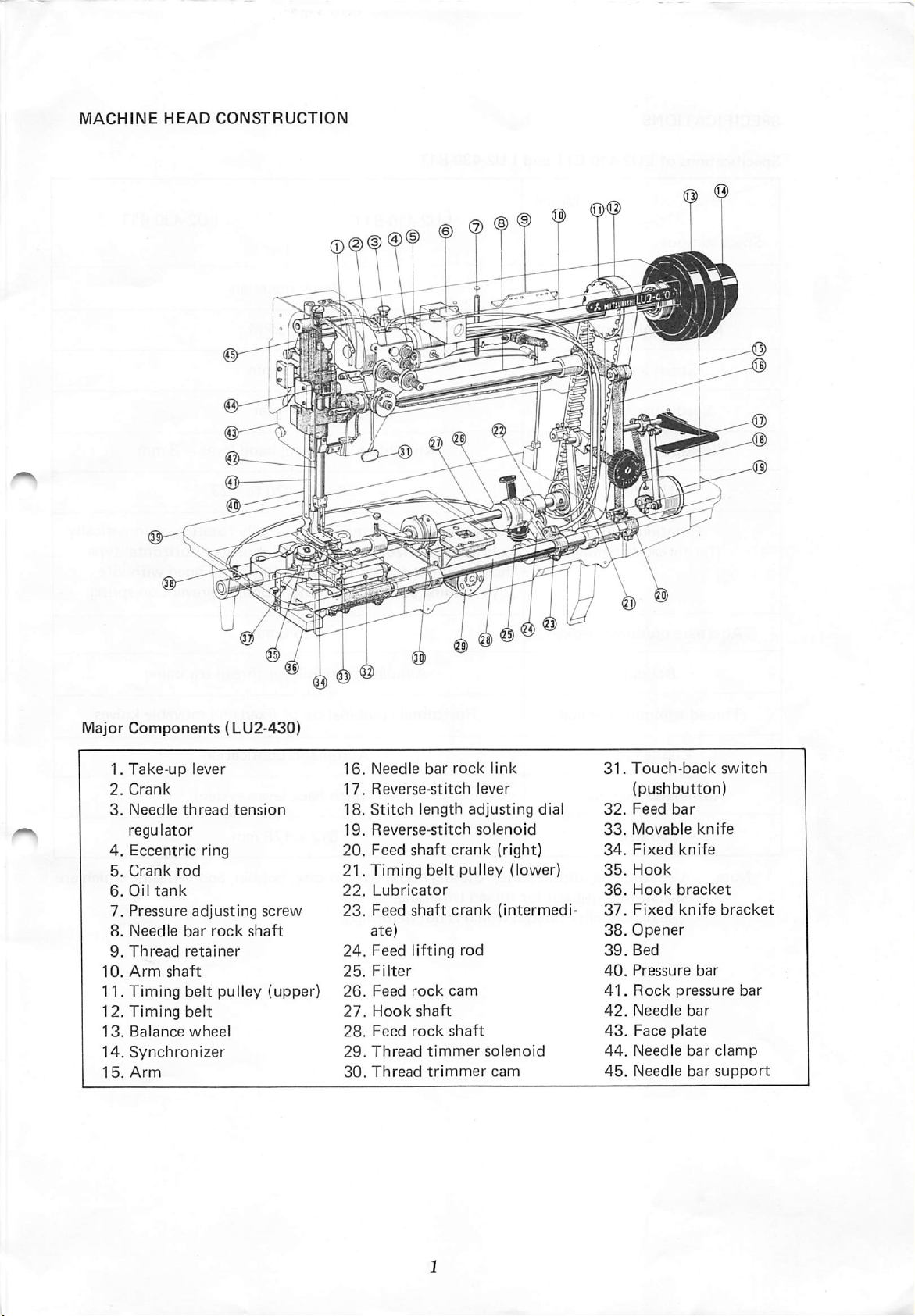
1.
Take-up
2.
Crank
3.
Needle
regulator
4.
Eccentric
5.
Crank
6.
Oil
7.
Pressure
8.
Needle
9.
Thread
10.
Arm
11.
Timing
12.
Timing
13.
Balance
14.
Synchronizer
15.
Arm
tank
thread
rod
bar
retainer
shaft
belt
belt
lever
ring
adjusting
rock
pulley
wheel
tension
screw
shaft
(upper)
16.
Needle
17.
Reverse-stitch
18.
Stitch
19.
Reverse-stitch
20.
Feed
21.
Timing
22.
Lubricator
23.
Feed
ate)
24.
Feed
25.
Filter
26.
Feed
27.
Hook
28.
Feed
29.
Thread
30.
Thread
bar
length
shaft
belt
shaft
lifting
rock
shaft
rock
timmer
trimmer
rock
lever
adjusting
solenoid
crank
pulley
crank
rod
cam
shaft
link
(right)
(lower)
(intermedi
solenoid
cam
dial
31.
Touch-back
(pushbutton)
32.
Feed
33.
Movable
34.
Fixed
35.
Hook
36.
Hook
37.
Fixed
38.
Opener
39.
Bed
40.
Pressure
41.
Rock
42.
Needle
43.
Face
44.
Needle
45.
Needle
bar
knife
knife
bracket
knife
bar
pressure
bar
plate
bar
bar
switch
bracket
bar
clamp
support
Page 5
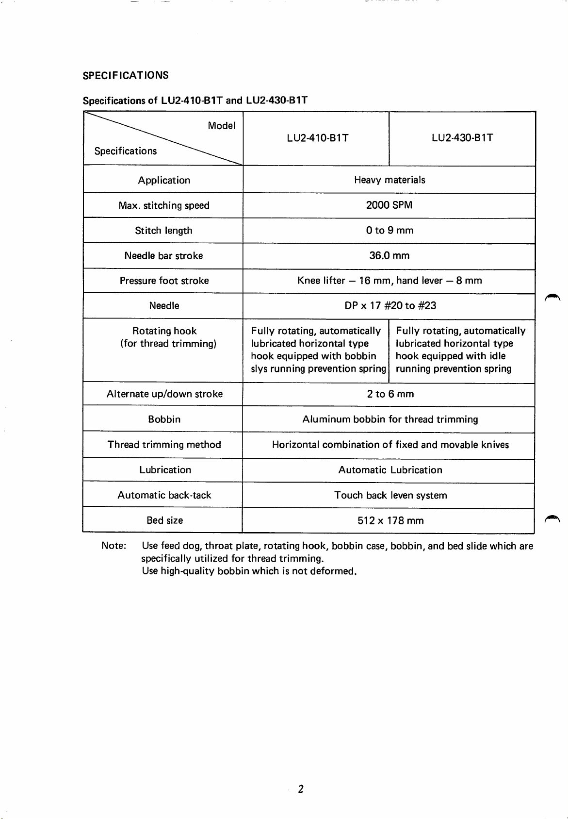
SPECIFICATIONS
SpecificationsofLU2-410-B1T
Model
Specifications
Application
Max.
Stitch
Needle
Pressure
Rotating
(for
thread
stitching
Needle
length
bar
stroke
foot
stroke
hook
trimming)
speed
and
LU2-430-B1T
Fully
lubricated
hook
slys
LU2-410-B1T
rotating,
equipped
running
Knee
lifter—16
automatically
horizontal
with
prevention
Heavy
2000
0to9
36.0
DPX17
type
bobbin
spring
materials
SPM
mm
mm
mm,
hand
#20to#23
Fully
lubricated
hook
running
LU2-430-B1T
lever —8
rotating,
horizontal
equipped
prevention
mm
automatically
type
with
idle
spring
Alternate
Thread
Automatic
up/down
Bobbin
trimming
Lubrication
back-tack
Bed
size
method
Note: Use feed dog,
specifically
Use
high-quality
stroke
throat
utilized
bobbin
plate,
for
thread
whichisnot
Horizontal
rotating
trimming.
Aluminum
combination
Automatic
Touch
hook,
bobbin
deformed.
2to6
bobbin
of
back
512X178
case,
mm
for
thread
fixed
Lubrication
leven
system
mm
bobbin,
trimming
and
movable
and
bed slide which
knives
are
Page 6
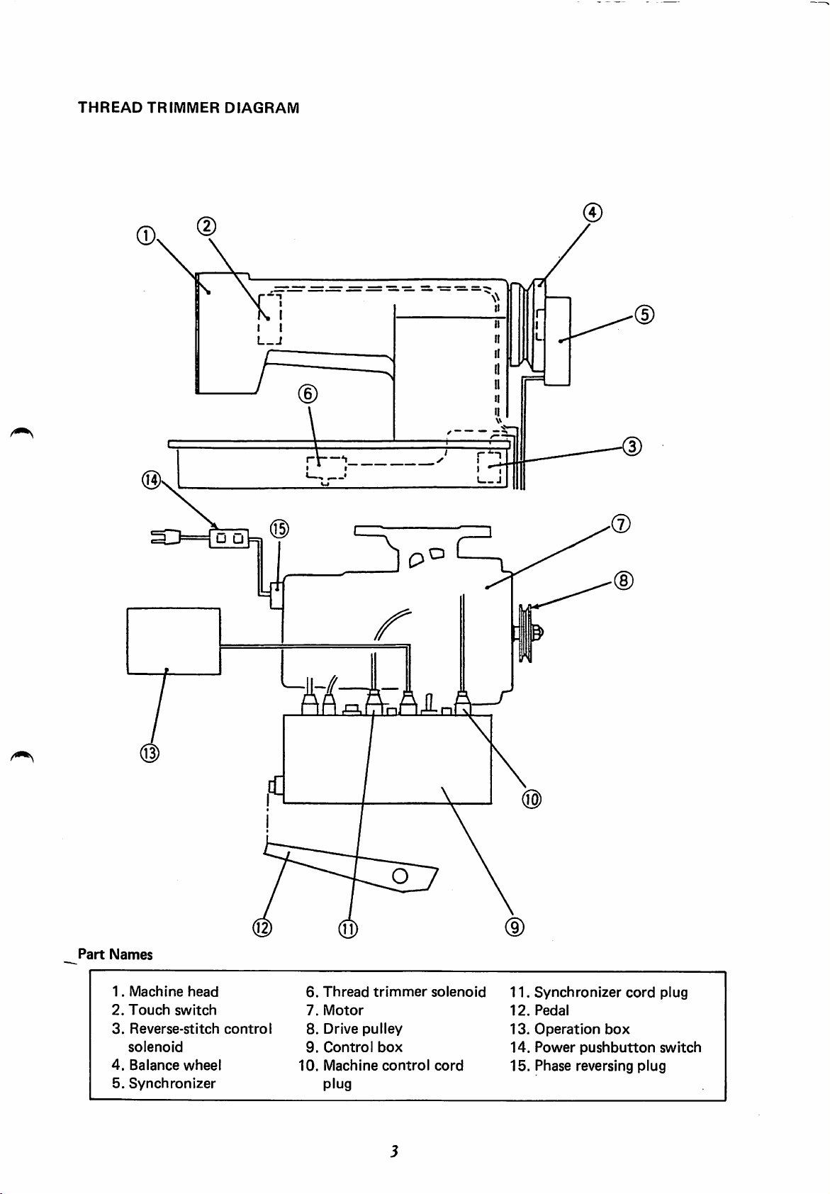
THREAD
TRIMMER
@
DIAGRAM
Part
Names
1.
Machine
2.
Touch
3.
Reverse-stitch
solenoid
4.
Balance
5.
Synchronizer
head
switch
wheel
control
Af(gl.A-rnAiLr.i
6.
7.
8.
9.
10.
Thread
Motor
Drive
Control
Machine
plug
trimmer
pulley
box
control
solenoid
cord
11.
12.
13.
14.
15.
e>
Synchronizer
Pedal
Operation
Power
Phase reversing
box
pushbutton
cord
plug
plug
switch
Page 7
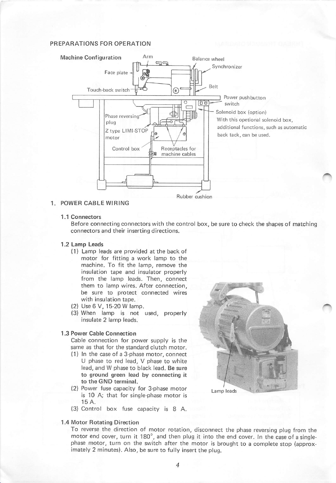
PREPARATIONS
FOR
OPERATION
1.
Machine
POWER
1.1
Connectors
Before
connectors
Configuration
Face plate
Touch-back
Phase
plug
Ztype
Control
CABLE
WIRING
connecting
and
switch'
reversing
LIMI-STOP
connectors
their
inserting
txDx
^
with
directions.
Receptacles
machine
Rubber
the
control
Balance
/
for
cables
wheel
Synchronizer
Solenoid
With
additional
back
cushion
box,besuretocheck
I Power
switch
this
tack,
pushbutton
box
(option)
opetional
functions,
canbeused.
the
solenoid
box,
suchasautomatic
shapesofmatching
1.2
1.3
Lamp
(1)
{2}
(3)
Power
Cable
same
(1) In
(2)
(3)
Leads
Lamp
motor
machine.
insulation
from
them
be
sure
with
insulation
Use6V,
When
insulate2lamp
Cable
connection
as
that
the
U
phasetored
lead,
andWphasetoblack
to
ground
Power
is 10 A;
15
A.
Control
leads
are
providedatthe
for
fittingawork
To
fit
tape
and
the
lamp
to
lamp
wires.
to
protect
tape.
15-20Wlamp.
lamp
caseofa
is
leads.
Connection
for
for
the
3-phase
lead,Vphasetowhite
green
fuse
capacity
that
for
box
fuse
back
lamp
to
the
lamp,
insulator
leads.
After
not
power
standard
remove
Then,
connection,
connected
used,
supplyisthe
clutch
motor,
properly
connect
wires
properly
motor.
connect
lead.Besure
leadbyconnecting
for
3-phase
single-phase
capacity
motor
motor
is 8 A.
of
the
the
w•
li
nilfc
JK'.j-
it
is
^
|
mniii
s-,
k
u
'$
I
JUBf
1.4
Motor
To
Rotating
reverse
Direction
the direction of motor rotation, disconnect the phase reversing plug from the
motor end cover, turn It 180°, and then plug it into the end cover. In the case of a
phase motor, turn on the switch after the motor is broughttoa complete stop (approx
imately 2 minutes). Also, be suretofully insert
the
plug.
single-
Page 8
2.
CONNECTION
Wire
Note: (1)
the
WITH
control
boxasshownatright.
For
the
connecting
connectors,
the
power
(2)The
head
as
mind
specified
combination
and
when
headorcontrol
CONTROL
sakeofsafety,
or
disconnecting
be
suretoturn
switch.
motor
control
below.
correct
replacing
combination
the
box.
of
BOX
before
off
machine
box
Keep
machine
Round
holeintable
Solenoid
is
box
in
Clutch
Brake
External
volume
Position
the
timing marks are
1/2
select
switch
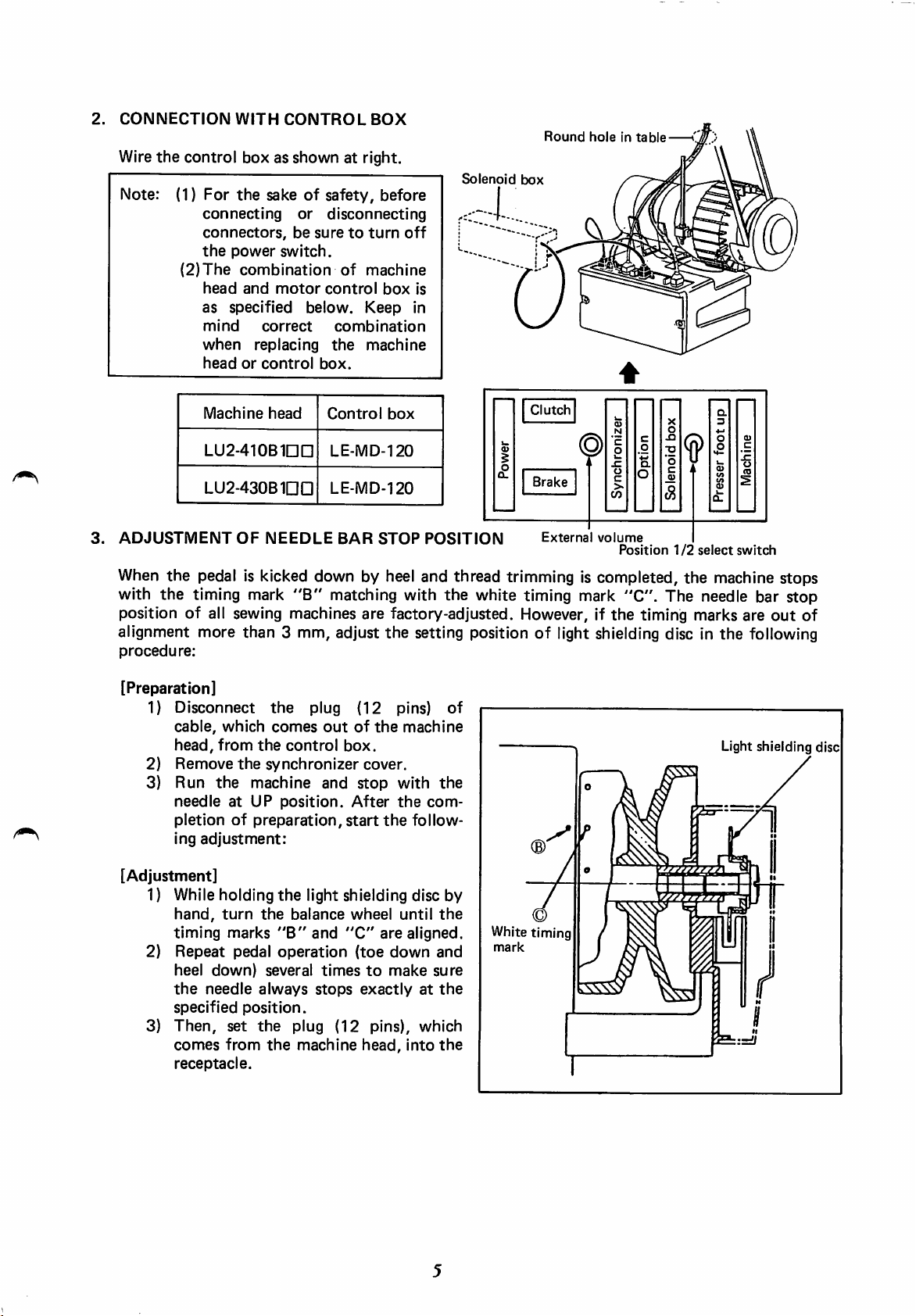
3.
ADJUSTMENT
When
with
Machine
LU2-410Binn
LU2-430BinD
the
pedal is kicked down by heel and thread trimming is completed, the machine stops
the
timing mark
OF
head
NEEDLE
"B"
Control
LE.MD-120
LE-MD-120
BAR
box
STOP
matching with
POSITION
the
white timing mark "C". The needle bar stop
position of all sewing machines are factory-adjusted. However, if
alignment more than 3 mm, adjust the setting position of light shielding disc in the following
procedure:
[Preparation]
1)
Disconnect
cable,
which
head,
from
2) Remove
3) Run
the
needle
pletionofpreparation,
ing
adjustment:
the
the
the
synchronizer
machine
at
UP
plug
comes
control
position.
(12
outofthe
box.
cover.
and
stop
After
start
pins)
machine
with
the
the
of
Light shielding disc
the
com
follow
out
of
[Adjustment]
1) While holding
hand,
turn
timing
Repeat
2)
heel
the
specified
3)
Then,
comes
receptacle.
marks
down)
needle
set
from
the
pedal
several
always
position.
the
the
the
light shielding disc by
balance
"B"
operation
plug
machine
wheel
and
"C"
are
(toe
down
timestomake
stops
exactlyatthe
(12
pins), which
head,
until
aligned.
and
sure
into
the
Whitetiming
mark
the
Page 9
NOTE
1.
ON
USE
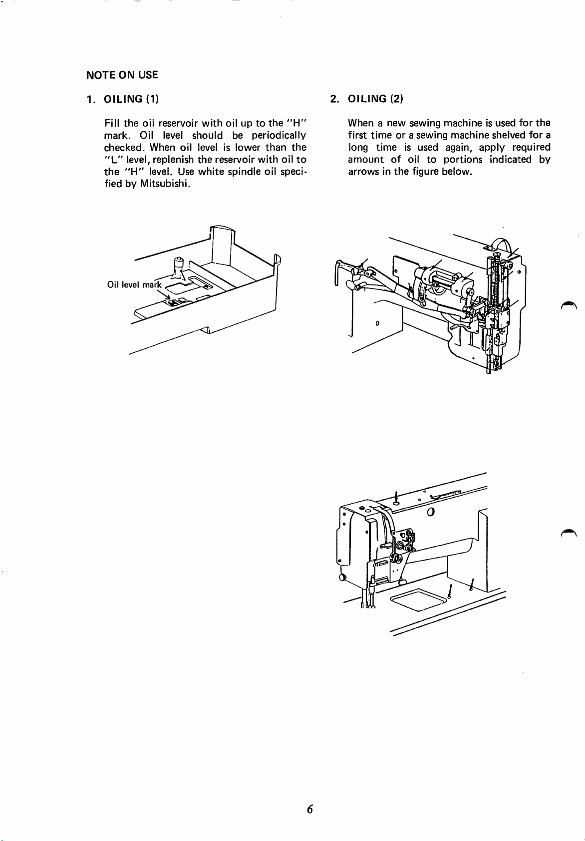
OILING
Fill
mark.
checked.
"L"
the
fiedbyMitsubishi.
the
level,
"H"
(1)
oil
Oil level
reservoir
When
level. Use
oil
replenish
with
oilupto
should
levelislower
the
white
be
reservoir
spindle
the
"H"
periodically
than
the
with
oil
to
oil
speci
2.
OILING
When a
first
long
amount
arrowsinthe
(2)
new
timeora
time
is
of
sewing
sewing
used
oil
to
figure
machine
machine
again,
portions
below.
is used
shelved
apply
indicated
for
the
for
required
by
a
Oil
level
5
Page 10
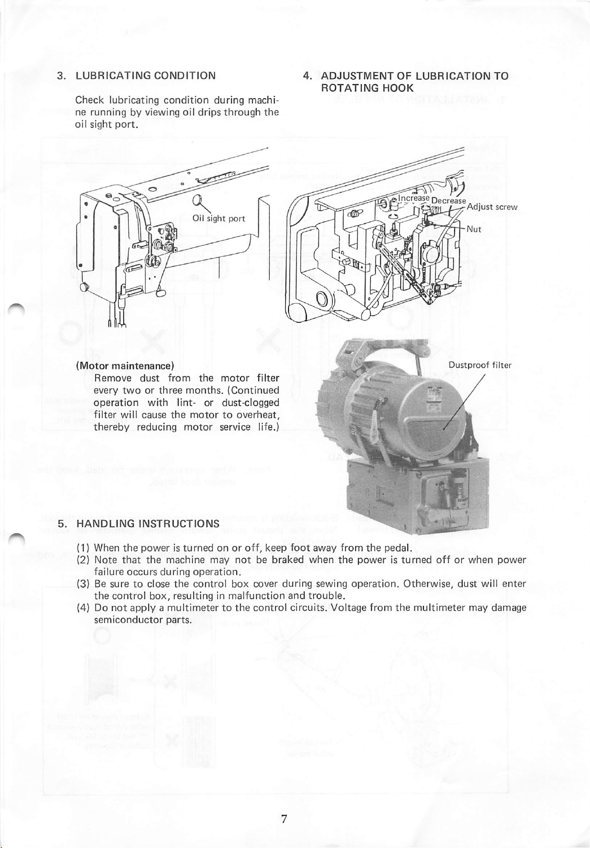
3.
LUBRICATING
Check
ne
oil
CONDITION
lubricating
runningbyviewing
sight
port.
condition
oil
drips
during
through
machi
the
4.
ADJUSTMENT
ROTATING
OF
HOOK
LUBRICATION
TO
(Motor
Remove
every
operation
filter
thereby
I
maintenance)
dust
two
or
three
with
will
cause
reducing
from
the
motor
months.
lint-
or
dust-clogged
the
motortooverheat,
motor
service life.)
filter
(Continued
I
[ncrease
Decrease
Dustproof
^
Adjust
screw
filter
5.
HANDLING
(1) When
(2)
(3) Be
(4) Do
INSTRUCTIONS
the
poweristurned
Note
that
the
failure
the
semiconductor
occurs
suretoclose
control
not
applyamultimetertothe
machine
during
box,
parts.
may
operation.
the
control
resulting in
onoroff,
not
box
malfunction
keep
be
braked
cover
control
foot
during
and
circuits.
away
when
sewing
trouble.
Voltage
from
the
the
poweristurned
operation.
from
pedal.
Otherwise,
the
off
multimeter
or
dust
when
will
may
power
enter
damage
Page 11

HOW
TO
USE
1.
INSTALLATIONOF
Put
each
until it
socket
prime
Then
needle
stopsatthe
and
grooves
tighten
THE
SEV\/ING
NEEDLES
into
needle
bottomofneedle
turn2needlessothat
face
each
set
screws.
socket
other.
O
.
Position
their
facing
needles
prime
each
MACHINE
Needles
Needles «
their
inserted.
with
grooves
other.
are
not
Note:
fully
X
Install
Needles
wrong
needles
are
direction.
set
after
in
X
turning
off
1
the
Needle
power.
2.
WINDING
[Adjustment]
OF
BOBBIN
Tensionofwound
Conically
wound
Quantityofwound
THREAD
thread:
thread:
thread:
Note:
Slack winding is
Move
thread
Loosen
the
layer.
the
thread
thread
tightentodecrease,
Thread
adjust
Thread
adjut
tension
nut
Thread
length
screw
When
operating
presser
recommended
guide
toward
quantity
the
quantityofwound
guide
under
foot
lifted.
for
polyester
smaller
adjusting screw
no
load,
and
nylon
diameter
to
thread.
keep
threads.
of
wound
increase,
the
and
Page 12

3.
SELECTION
It is
needle
the
depending
needles.
4.
THREADING
OF
recommended
(viewed
right
needle.
on
For
OF
THREAD
to
use
"8"
from
front)
When
needles, use
it is
"Z"
bobbin thread,-
NEEDLE
THREADS
twist
and
difficult
twist
either
"Z"
thread
twist
to
thread
thread
for
thread
use
for
the
threads
both
will
left
for
do.
. S
"Z"
twist
twist
A B
thread
thread
ABA
(1) Pass each needle thread through thread guide
Note: When
or
through
(2) With
the
position,
showninthe
Note: Pressing
button
tension
threadtobe
Needle thread tension regulator
(HD®®
thin
slippery
thread
(such as polyester
filament thread) is used, pass
thread
take-up lever located at
pass
each
figure
the
needle
below.
needle
guide
thread
"B"
thread
and
the
tension
(shown in figure below) will
disc,
thereby
allowing
picked up easily.
button
®(0
the
then
uppermost
in
the
regulator
open
the
"A".
thread
"A".
order
the
needle
iijLd
llMCiiD
Lead
thread
leftward. rightward.
Lead
thread
(Expanded
view)
Thread
Page 13

5.
ADJUSTMENT
OF
STITCH
LENGTH
AND
REVERSE
SEWING
(TOUCH
BACK)
To
make
stitch
length smaller, lower
stitch length adjust lever
length
adjust
Stitch
dial.
length
Stitch
adjust
length
and
turn
dial
adjust
the
lever
the
stitch
Touch-back
.... Direction
by pressing
oninreverse
is pressed,
direction
switch
of
when
stitching
this
direction
and
the
can
switch.
Stitching
while
*returns in forward
button
^
Touch-back
* switch
be reversed
goes
the
button
is
released.
6.
SETTING
(1)
Mount
the
(2)
Then
pull.
spring
* When
OF
bobbin
thread
pass
The
and
bobbin
indicated
BOBBIN
is
wound
the
thread
comes
the
should
by
thread
thread
into
clockwise.
through
passes
outofthe
bobbin
thread
rotate
arrowinthe
bobbin
the
under
slit
in
figure.
casesothat
slit
the
"2".
is
pulled,
the
direction
"1"
and
tension
the
Slit
SIt"2
"1
I
10
Page 14

7.
THREADING
(1)
Mount
set
the
the
bed.
the
latch
OF
bobbin
"1".
BOBBIN
caseinthe
Keep
THREADS
hook
thread
end
and
over
9.
BALANCE
OF
THREAD
TENSION
Thread
(2) Pick up 2 needle
and
rotate
right
threads
bobbin
and
and
led
hand.
as
threads
needle
backward.
the
balance
By pulling up
shown
threads
Opener
threads
are
—
wheel1turn
in
the
lifted.
Both
should
by
the
figure,
be
left
needle
bobbin
aligned
Thread
hand
by
the
10.
AO
BX
CX
TENSION
Needle
adjusted
tension.
To
each
needle
and
stroke
OF
adjust
tension
thread
thread
of
Balanced
Tight
bobbin
Loose
bobbin
NEEDLE
thread
with
tension
respecttobobbin
needle
adjusting
tension
by
changing
slack
thread
needleorloose
thread
needleortight
thread
THREAD
thread
nut.
for
take-up
tension
tension
tension
should
tension,
Also
special
force
be
thread
turn
adjust
fabric
and
spring.
8.
TENSION
THREADS
ADJUSTMENT
OF
BOBBIN
Loosen
11.
ADJUSTMENT
PRESSURE
Adjust
turning
Loosen^^^S
pressure
the
Thread
OF
PRESSER
depending
pressure
Tighten
adjusting
.
Pressure
tension
FOOT
on
adjust
fabrics
adjust
nut
by
screw.
screw
Tension
adjust
screw
Tighten
11
0
0
r»
A
Page 15

12.
TIMING
(1)
Set
(2) When
lowermost
the
locations:
ADJUSTMENT
stitch
length adjusting dialto"6".
the
needle is lifted
position,
needle
The
2.3
The
center
Gap
face
should
upper
mm
below
hook
of
between
of
needle
point
needle
FOR
the
be
locatedatthe
edgeofneedle
the
hook
should
axis.
the
hook
should
ROTATING
2.4
mm
rotating
eye
point.
be
locatedatthe
point
be
0.05
mm.
from
hook
following
should
and
the
HOOK
its
and
be
side
AND
NEEDLE
Hook
Upperedge
needle
Needle
2.4
Needle
lowest
Center of €
needle
2.3
mm
pointNy
l
of^
eye
lifted
at
position
0.05
' i n
mm
mm | l
(3) Needle
be
adjusted
* Easy
ing
dog
Positioning
(1)
With
mesh
with
located
driving
located
(2)
Tighten
of
(3)
Guideofrotating
When
position,
is
*
To
needle
gear (large)
(large) 1
and
rotating
in
adjustment
the
presser
before
the
hook
the
the
the
at
gear
at
adjutment.
needle
right
large
front,
(small) so
rear.
"8"
hook
shaft.
the
needle
the
nearlyinline
make
fine
motions,
to
2 mm in
hook
the
following
can
be
foot,
throat
point
at
lowermost
hand
driving gear (small)
gearsothat
and
mesh
screws
onto
hook
is
"C"
screwinrotating
with
the
adjustment
loosen
and
move
positions
made
plate,
that
the
position
at
its
needle.
screw
the
the
axial
procedure:
by
remov
and
position,
"8"
screw
the
left
hand
"8"
screw
set
contact
lowermost
hook
of
hook
in
driving
driving gear
direction.
can
feed
and
Hook
point
r(
) 5
is
is
X
X
X
X
X
X
1to2
mm
1to2
mm
Needleatlowest
position
12
Page 16

13.
ADJUSTMENT
The
foot
OF
heightoffeed
should
Light
be
fabric
positionistoo
ssureistoo
The
stitch
strong.
lengthofheavy fabric will
uniformifthe
the
presser
Measure
the
balance
feed dog
throat
Light
Normal
Heavy
foot
the
at
plate.
fabric
fabric
fabric
FEED
dog
adjusted
will be
DOG
and
the
depending
damagedifthe
highorthe
feed
dog
positionistoo
pressureistoo
height
wheel
the
of
feed
by
hand
highest position from
Approx.
...
throat
.Approx.
throat
plate
plate
Approx.
throat
plate
HEIGHT
pressureofpresser
on
fabrics.
feed
dog
presser
dog
and
weak.
locating
foot
by
pre
not
low
turning
the
be
or
the
0.8
mm
above
1.0
mm
above
1.2
mm
above
V///.
T~
;0.8
mm
mm
Adjusting
(1)
(2)
(3)
Procedure
Lean
Turn
it
when
mum
Loosen
the
the
height
(4) Vertically move
direction indicated by
to
locate
(5)
The
After
bar
feed
set
dog
height
screw.
machine
balance
the
feed
the
feed
the
feed dog
adjustment,
height is
head
wheel
dog rises
above
bar
set
the
factory-set
backward.
by
hand
and
to
the
the
throat
screw.
feed bar (in
arrowinthe
at
proper
tighten
at
1.2
maxi
plate.
figure)
height.
the
stop
the
feed
mm.
Feed
screw
bar
13
Page 17

14.
RELATION
When
the
the
relation
lever
motions
BETWEEN
ROTATING
HOOK
timing belt is removed for replacement,
between
shouldbeas
rotating
follows:
hook
and
(1) Turn the balance wheel and stop it when the
take-up lever is lifted
(2) Lean
sure
the
machine head backward and make
the
arrow
belt sprocket matches
bossofhook
(3) If
the
shaft
timing mark is
black line, remove
belttoobtain
(timing mark)
proper
to
the
bearing.
not
and
alignment.
its
top
on
the
black line on
aligned with the
reinstall
the
AND
take-up
position.
timing
the
timing
TAKE-UP
LEVER
MOTIONS
15.
RELATION
(1)
(2)
(3) If
BETWEEN
Turn
the
balance wheel by
when
the
opener
away
from
the
At
this
time,
the
bobbin
approximately
the
gap is
opener
of
opener.
set
screw
make
case
throat
holder
0.2
too
ROTATING
HOOK
hand
holderisthe
plate.
sure
mm.
that
"A"
longest
the
and
gap
the
largeorsmall, loosen
"B"
and
adjust
the
and
distance
between
opener
position
AND
stop
it
is
the
OPENER
Approx.
MOTIONS
0.2
mm
Timing
Black
Timing
Timing belt
sprocket
mark
(arrow)
belt
line
Opener
14
Screw
"B'
Opener
holder
Page 18

16.
RELATION
(1)
Set
(2)
Lean
(3) Loosen
and
(4) Lower
BETWEEN
the
stitch length adjust dial
the
machine
the
feed
"B".
the
needle
(5) Allow 9-mm gap between
the
rock
pressure bar (10.1 mm
and
420).
Then
crank
(6) Check
is
connected
as
showninthe
(7) If
the
remove
to
obtain
(8) After
tighten
xrews
"A"
to
see if
with
connection
the
back
the
right angles.
the
completion of adjustment, fully
the
screws
NEEDLE
head
backward.
shaft
crank
to
its lowest
the
finger-tighten
and
"B".
the
right feed
the
link at right angles
figure.
is
not
cover
and
"A",
AND
FEED
to
"0".
set
screws
"A"
position.
pressure bar
for
the
shaft
LU2-400
feed
shaft
crank
and
at right angles,
loosen
"B",
"C"
and
screw
"C".
DOG
MOTIONS
Screw
Screw
"A"
"B
Feed
shaft
crank
Feed
(intermediate)
shaft
crank (right)
Link
LU2-410and
LU2-400
and
430
420
-
Needle
Rock
bar
pressure
Feed
Dimension
9.0
mm
10.1
mm
bar
shaft
A
crank
Screw
(right)
"8
Link
Screw
"C
15
Page 19

17.
SAFETY
The
belt
runs
by
the
(1)
Function
1)
2)
3)
(2)
Setting
1)
2)
3) Release
4)
CLUTCH
safety
from
under
hook
When
(SAFETY
clutch
prevents
being damaged
excessive
load
caughtinthreads.
the
safety
DEVICE)
hook
when
which
clutch
the
is
timing belt pulley races, causing
shaft
to
stop
and
only
the
arm
keep
turning.
the
machine.
Remove
from
the
Turn
hand
hook
nism
back
the
to
shaft.
Therefore,
threads
hook.
timing
check
Then
again.
and
belt
for
other
set
pulley
smooth
the
immediately
foreign
clutch
Procedure
While
button,
of
balance
tion
Now
intermeshing
mechanism.
again
kept
The
showninthe
simultaneously
whichislocatedonthe
bed,
by
left
hand,
wheel
by
right
shownbyarrowinthe
the
with
balance
further
the
wheelisstopped
plate
providedinthe
Then
turn
greater
pushbutton
pressed.
clutch
mechanism
figure.
pressing
slowly
handinthe
figure.
the
balance
force.
which
is
now
and
timing
machine
is
caused
actuated,
the
shaft
matter
bushing
rotation
mecha
the
other
turn
by
clutch
wheel
has
set
hook
stop
by
push
side
the
direc
the
been
to
of
Safety
switch
Timing belt pulley
Bushing
Balance
as
wheel
Pushbutton
18.
ADJUSTMENT
SIDE)
When
on
of
STROKE
stitchingisnot
fabrics,
slot
adjust
in feed
[Adjusting Procedure]
1)
Loosen
2) When
the
upper
3) When
stroke
feeds
point
rock
of
special
4)
After
OF
the
rock
the
special
this
bolt
feed
this
boltisset
decreases.
are
theoretically
where
shaft
the
crankisaligned
bolt.)
adjustment,
UPPER
made
upper
bolt.
is
stroke
(The
reference
tighten
FEED
uniformly
feed
shaft
set
at
increases.
at
upper
equivalent
stroke
crank
upper
lower
line
with
the
special
(NEEDLE
depending
by
range
(right).
position,
position,
and
lower
at
the
for
feed
the
center
bolt.
Pushbutton
joint
portion
Intermeshing
F^ed rock shaft crank (right)
Upper
Reference
Special
[(needle bar rock link)
Upper
bolt.
feed
feed
plate
stroke
stroke
16
Page 20

19.
ADJUSTMENT
(1)
(2)
(3)
OF
Operating
Height
OUTER
Adjustment
AND
INNER
PRESSER
When springy material is sewnorwhen
thickness
heightofpresser
changes
greatly,
foot.
adjust
the
operating
[Adjusting Procedure]
1) Loosen
2)
3)
4)
Alternate
The
best
changing
outer
fabrics.
Example:
and
When
vertical
increase
prevents
Setting
upper
heightofinner
Setting
decreases
After
bolt.
The
between
the
special
the
crank
position
the
bolt
the
height.
adjustment,
heightofpresser
2
mm
Up/Down
feed
the
inner
slippery
stroke
that
Strokes
condition
alternate
presser
fabric
of
of
inner
slipping.
bolt.
rod
special
increases
and
outer
at
lower
tighten
feetisadjustable
and6mm.
can
be
up/down
feet
is
outer
presser
presser
bolt
the
operating
presser feet.
position
the
special
obtained
strokes of
depending
sewn,
reduce
foot
foot.
[Adjusting Procedure]
1)
Turn
the
2)
3)
4)
5)
6)
Mounting
Turn
1)
the
2) In
this
eccentric
tighten
balance
when
lowest
Lower
Loosen
feed
Moving
increases
presser
outer
the
position.
the
the
lifting
the
foot
presser
take-up
presser
rock
the
Reversely, moving it
reduces
presser
presser.
After
screw
presser
thatofouterat3.2
the
needle
the
and
adjustment,
"A".
footisfactory-setat2
the
Eccentric
balance
bar
state,
locate
ring as
it.
wheel
lever
bar
lifter.
screw
shaft
crank
vertical
"A"
crank.
"B"
stroke
and decreases
foot.
vertical
increases
motion
that
securely
(Vertical
stroke
mm.)
Ring
wheel
at
the
by
highest
No. 1
showninthe
and
reaches
in
to
to
tighten
hand
screw
stop
the
the
of
that
the
of
of
of
mm
to
position.
"C"
figure
the
by
on
and
This
upper
left
inner
right
inner
outer
the
inner
and
bring
and
FEET
Upper feed lifting rock shaft crank
Special
bolt/O
Screw
at
Lower
Crank
Uniform
Non-uniform
Arm
rod
vertical
motion
vertical
it
its
of
Eccentric
No.1screw
in
No.2screw
"O
Crank
"B
ring
"A
Uniform
(Higher)
Inner
presser
Outer
presser
motion
(Lower)
b)—
Upper feed lifting
rodshaft
foot
foot
Arm
crank
"8'
\
17
Page 21

ADJUSTMENT
1.
INSTALLATION
1.1
Initial
(1)
(2) With
(3) In
(4)
(5) Adjust
Thread
trimmer
rocking
crank
OF
THREAD
OF
MOVABLE
Position
Turn
onto
this
on
the
necessary
roller
Loosen
knife
of
Movable
the
balance wheel by hand until
the
needles at this position, push
the
thread
state,
trimmer
turn
arm is aligned with
work
on
from
slipping
the
bolts
the
movable knife so
bladeasillustratedinthe
Bolt
"A
TRIMMER
KNIFE
Knife
cam
the
balance wheel and
the
cam follower crank using screw
outofthe
"A"
and
"B"
the
groove.
the
white point on
cam
groove.
on
the
that
its slant
figure.
needles reach
the
cam follower cranktolocate
stop
their
it at
the
point
the
balance wheel. At this time, make
and
thread
Then
trimmer
portion
tighten
rocking
protrudes0to
the
bolts
lowest position.
the
cam roller
where
the
black
screwdriver to prevent
crank.
0.5
"A"
Movable
mm from
and
"B".
knife
the
point
the
fixed
1.2
GAP
BETWEEN
(1)
Turn
needles
(2) With
cam
ance
knife
(3)
Turn
the
the
the
holder
by
the
balance
reach
the
needlesatthis
follower
wheel
reaches
the
bobbin
direction
figure.
movable
stopper
loosening
MOVABLE
wheel
their
crank.
by
hand
the
endofits
case
indicated
Then
adjust
knife
to
approximately
the
0
Thread trimmer rocking crank
Then
until
holder
and
screws
KNIFE
by
lowest
position,
by
the
the
hand
turn
the
stroke.
the
gap
bobbin
"A"
AND
until
position.
push
the
movable
by
arrow
between
0.5
and
hand
Bolt
BOBBIN
the
the
bal
in
in
case
mm
"B".
0~
"B"
Bobbin
stopper
0.
CASE
Movable
case
Approx,
HOLDER
knife->
holder
0.5
mm
STOPPER
Screw
Screw
Bobbin
Fixed
"A'
"B"
case
knife
holder
18
Page 22

2.
POSITIONING
(1)
(2)
Adjust
bushing
shaft
After
contact
release
(i.e.
after
OF
the
gap
between
to
17.3
set
screw
"A".
bringing
with
cam
the
the
with
eliminating gap),
THREAD
mm
and
thread
bushing,
the
the
trimmer
thread
tighten
TRIMMER
feed
cam
tighten
and
the
trimmer
the
cam
set
CAM
and
the
hook
into
tension
cam
screws.
Bracket
3.
ADJUSTMENT
(1)
(2) With
(3) By
OF
Turn
cam
onto
the
needles
turning
thread
knife
the
balance
point
the
reach
the
follower
the
starts
on
the
balance
needles
groove
the
trimmer
moving
wheel is aligned
loosen2thread
"A".
THREAD
their
crank
wheel
lowest
at
of
this
to
by
position.
position,
locate
thread
balance wheel by
cam
so
when
the
arm.
To
make
trimmer
cam
TRIMMER
hand
the
cam
trimmer
hand,
that
the
green
with
this
adjustment,
clamp
until
push
movable
point
the
screws
•Tension
CAM
the
the
roller
cam.
adjust
on
black
release
1
Arm
cam
cam
Thread
Bushing
0
trimmer
Black
Screw
i
point
cam
Green
"
point
I
Feed
Feed
cam
Balance
rod
wheel
Cam
c_
Cam
follower
roller
crank
0
Screw
"A"
Cam
groove
Thread
trimmer
cam
19
J
Page 23

4.
ADJUSTMENT
(1)
Turn
the
(2) With
(3) By
the
the
grooveofthread
turning
tension
point
(4)
Adjust
mounted on
adjustment,
(5)
For
fine
(6) When the nuts
degree
OF
balance
needlesatthis
the
disc closes
on
the
arm.
the
opening
the
loosen
adjustment,
increases.
THREAD
wheelbyhand
balance wheel by
when
For
degreeoftension
convexed portionofthread
the
"D"
RELEASER
until
the
position,
trimmer
the
this
nut
loosen
push
cam.
hand,
white
adjustment,
"C"
and
the
nuts
needles reach
the
cam
follower
adjust
point
on
the
the
loosen 2 tension release cam clamp screws
disc
with
the
release cam as shown in
draw
the
wire.
"D"
(0.5to0.7
the
lowest
cranktolocate
thread
position.
the
tension release cam so
balance wheel is aligned
tension
release lever
roller
the
mm).
cam roller
with
figure.
are loosened and the outer casing is shifted rightward, the opening
White
Arm Black
point
point
/ Balance wheel
"B"
that
the
which
For
onto
the
black
"A".
is
this
Tension
Roller
Thread
release
Screw
"A
"B
release
Thread
lever
cam
trimmer
cam
Screw
(dI
(D
"C"
Cam
Cam
follower
roller
crank
Outer
' Largeropening degree
J
casing
20
Page 24

5.
ADJUSTMENT
OF
MOVABLE
AND
FIXED
KNIFE
MESHING
PRESSURE
(1) Loosen
the
fixed knife bracket clamp
bolt
"A".
(2) Turn the vertical position adjust screw "B" to adjust the
the
bolt
"A".
Note; Since excess scissoring pressure causes large
nism
and
(3) Move
results in
minimum
the
movable knifetocheckifthe
pressure.
trimming
failure,
thread
C0P
Fixed
knife
bracket
Bo
t "
adjust
is sharply
torquetothe
it so
meshing
that
the
trimmed.
pressureand then tighten
thread trimming mecha
thread
canbetrimmed
with
6.
SHARPENING
When
movable
the
Vertical
cutting
THE
position
FIXED
adjust
KNIFE
edgeofknive is dull,
knifeisdifficulttosharpen,
Fixed
screw
"B'
sharpen
replaceitwithanew
knife
the
fixed knife as
Oilstone
one.
showninthe
figure. Since
the
21
Page 25

7.
ADJUSTMENT
Rocking crank
Connecting
"C
link-
Screw
OF
"A"
\
NEEDLE
Stopper
GAUGE
pin
DISTANCE
"E"
Screw
"A
Hook
(right)
bracket
Hook
bracket
(left)-
Screw
(1)
Lean
the
(2)
Loosen2connecting
(3) Replace
needle
(4)
Remove
(5)
Loosen
and
"B"toadjust
and
hooks.
(6)
When
adjusted,
(7) Make
tact
the
with
tighten
(8)
Turn
the
(9)
Loosen
(10) Push
(11)
the
is
smoothly
Adjustmentofcam
a) Push
b) By
turning
plane
c) Push
thread
0
Bolt
"J"
Stopper
machine
the
clamp.
the
spring
the
hook
the
needles
install
rocking
the
the
connecting
balance wheelbyhand
the
nuts
cam
placed
the
cam follower cranktoplace
"N"asshowninthe
the
cam follower
trimmer
pin
head
throat
"M".
bracket
the
the
spring
cranks
stopper
"G"
follower
onto
groove
the
connecting
cam
"F
backward.
link
plate,
gaps
and
pins
link
and
crank
the
crank
groove.
clamp
clamp
hooks
"M".
"C"
"E"
"H".
grooveofthread
and
Screw
Thread
crank
bolts
trimmer
"D"
feed dog,
screws
between
and
clamp
"K"
and
until
cam
have
"D"
"F",
bolt
and
roller
needles
been
the
adjust
the
rod
"L",
figure (within
againtocheck if
Spring "M
\
I
Connecting
rod
"L"
Nut"G"
"B"
rocking
"J".
and
"A"
Cam
con
and
"J".
needles reach
the
connecting
trimmer
cam roller
minimize
0.2
mm).
the
Cam
roller
groove
the
cam.
onto
the
gap
between
Then
cam roller is
tu
j •
thread
Plane
lowest
rod
"L"sothat
the
cam groove.
tighten
smoothly
—Cam
Cam
trimmer
Cam
follower
Thread
"N'
position.
the
cam roller
the
nuts
follower
cam
Hook
placed
roller
crank
trimmer
shaft
the
"G"
cam
and
onto
crank
"K'
cam
and
"K'
roller
the
"H".
the
Note:
When needle
width
exceeds
22
3/4",
change
the
connecting
rod
"L".
Page 26

8.
INSTALLATION
(1) Install
0.5—mm
the
9.
REMOVAL
(1)
Removal
The
without
unit.
(2) Remove
following
1)
2)
3)
•4)
6) With
6) Remove
7)
OF
SOLENOID
the
solenoid crank, providing a 0—
gap
between
solenoid
* Larger
into
during
malfunction
hook
crank.
gap
contact
solenoid
OF
HOOK
of
bracket
will
hook
cause
with
rotation,
of
BRACKET
bracket
(left)
disassembling
the
hook
procedure;
Remove
Remove
Remove
Remove
bracket
the
opener.
the
fixed
the
hook.
the
movable
the
lever raised, remove
by
shifting
indicatedbyarrowinthe
the
bobbin
spring.
Shift
the
leverinthe
remove
the
hook
bracket
CRANK
the
the
rotary
the
cam
solenoid
rollertocome
follower
resultinginthe "
thread
bracket (right) in
knife.
the
knife.
it in
arrow
trimmer
(left)
can
thread
figure.
thread
(right).
(LU2-430)
be
the
the
direction
direction
removed
trimmer
retaining
to
and
0--0.5»»
crank
unit.
Solenoid
the
knife
to
i
msi
crank
Knife
bracket
Movable
Bobbin
retaining
Fixed
Rotating
knife
thread
spring^
knife
hook
lE^
0
V
ssssw
Opener
Rotary
Cam
0
solenoid
Roller
follower
crank
Lever
10.
FEED
DOG,
(1) Since
used
(2) Slip
A
conical
to
during
(3)
Bobbin
Use
machine.
num,
the
*
Reassemble
reverse
the
for
thread
running
prevent
thead
the
it easily
THROAT
feed dog,
prevention
spring is
the
trimming.
bobbin
Since
deforms.
the
hook
procedure.
PLATE,
throat
HOOK, BOBBIN
plate,
trimming,besuretouse
spring
loadedinthe
bobbin
which
the
bobbin
To
from
is
attached
is
prevent
threadaslightlyaspossible.
brakcet
hook,
rotating
slip
made
bobbin case,
ones
hook
running
to
of
alumi
this,
wind
in
CASE,
specified
the
BOBBIN,
bobbin,
AND
and
by Mitsubishi.
BED
SLIDE
bed slide are specifically
Idle
running
spring
Rotating
prevention
hook
23
Page 27

11.
ADJUSTMENT
OF
NEEDLE
UP
STOP
POSITION
(LU2-410-B1T,
LU2-430-B1T)
The needle UP
thicknesses
stop
and
materialsofthreads
[Adjusting Procedure]
Perform stitching
point
on
the
1)
Advanced
and
balance wheel
needle
position,
thread
UP
stop
after
trimming
and
the
timing
and
thread
fabrics.
on
black
trimming, should be adjusted depending on
For
adjustment,
a sample
point
When deviation
trimming knife failstooperate, resulting in trimming
failure of both needle and bobbin threads at left and right.
on
and
the
proceedasfollows;
check
arm
"A"
deviation
when
is more than 2 mm, thread
needle
between
UP
motion
the
white
stops.
the
2)
Delayed
3)
Adjustment
If deviations are present as shown above, adjust
nizer until
needle
the
UP
stop
timing
•
specified dimensions
"A"
When
between
and
deviation
the
"B"
needle
"B"ismore
edge
and
than5mm,
throat
plate
light shielding disc portion of synchro
are obtained. For adjusting procedure, see
Section 3 "ADJUSTMENT OF NEEDLE BAR STOP POSITION" in page 5ofthe
tion Manual. When making
and
thread
trimming.
the
adjustment, check
the
stop position through actual stitching
clearance
reduces.
Instruc
24
Page 28

ADJUSTMENT
1.
SELECTION
AND
OF
USE
OF
POSITIONS
CONTROL
1
AND
SYSTEM
2
Select
When position 1 is selected,
the
2.
The 2-step pedal operation feature allows
riseofpresser
the
machine
• • :
stop
Position
Position
position by useofthe
2
1
the
thread is trimmed following a
select switch on
the
panel.
turn
by a heel-down operation on
pedal.
PEDAL
OPERATION
the
operation of run, thread trimming, and automatic
foot.
Pedal
Operation
Position
Pedal
Note 1: Variable speed run from lowtohigh speeds is available depending on pedaling strokes.
Note 2: Since presser
Note 3: Use optionally available Type LD-C2,
Position
Position
Operation
Setting
1
2
TOE
Needle
Needle
foot
rise is
DOWN
NEUTRAL
position.
stopsatDOWN
position.
to
stops
at UP
' ' ' /
/'
Neutral
outputtothe
11/
NEUTRAL
Pressure
Pressure
^
Toe
(machine
presser
04,or06
TO
foot
foot
Step
Step
SLIGHT
DOWN
goes up.
goes
2
1
up.
One
then
Needle
half
then
HEEL
down
start)
footupconnector,
solenoid box for tack-stitching.
Neutral
use solenoid valve (DC 24 V).
turn
turn
NEUTRAL
HEEL
and
thread
presser
fromUPto
and
thread
presser
foot
Heel
down
DOWN
foot
TO
trimming,
goes
up.
DOWN,
trimming,
goes
up.
3.
ADJUSTMENT
3.1
3.2
4.
ADJUSTMENT
(1)
OF
PEDAL
Adjustment
Pedal
changing
spring
pressure
unstable
Adjustment
After
"B"
to
ment,
of
tow-down
the
hooking
on
the
may
lever
of
loosening
adjust
tighten
OF
Pedal
pressure
lever.
cause
stop
Pedal
the
spring
and
secure
RUNNING
Tow-down
position.
Heel-down
nut
Adjustmentofmaximum
Two
volumes
exterior
maximum
volume
No.ofPoles
2
poles
To
select
"H".
Since
as
showninthe
tachometer,
for
changing
panel
to
of
low
control
speeds
"H"isfactory-setatthe
Internal
speeds
the
which
internal
following page, use
etc.
OPERATION
Force
canbeadjusted
positionofthe
Note
that
malfunction
Force
"A",
turn
pressure.
the
nut
SPEED
After
"A".
speed (speed
maximum
box.
The
which
have
following
Volume
2000
spm
are
outside
volume
"H"Ismarkedat2
PRESSURE
tension
too
weak
due
the
bolt
adjust
obtained
speed
external
been
speeds.
"H"
Setting
the
aforementioned
these
by
to
are
set
marks
Tension
when
provided
volume
by
the
locations
as guides.
spring
pedal is fully
inside
the
allows
adjustment
internal
Adjustable
Max.
range,
(with
For
stamped)
control
box
in
volume
RangebyExternal
adjust
2500
finer
"H".
speedto200
the
internal
spm
speed
and
B A
Lever
andonthe
the
The
Volume
spm
4500
setting,
range
internal
volume
spm)
use a
of
Page 29

Note:
Even if
internal
Speed
internal
the
volume
setting
volume
motor
jgOO
/ ,
"H"
spm
pulley
and
4500
diameterismade
external
volume
spm
larger,
cannot
External
speed
be
volume
obtained.
higher
Position
than
1/2
the
select
settings
switch
of
5.
M (Medium) (High) (Low) (Thread)
(W
(2)
H /
Adjustment
The
positioning
wise
increases
(This
volumeIsfactory-setat200
(3)
Adjustment
The
thread
increases
the
adjustment
dealer.
(4)
Adjustmentoftack-stitching
When
stitching
OPTIONAL
By
the
be
applied
details,
(1)
tack-stitchingismade
connections
consult
Internal
COR:
Correction
G:
Gain
A: High-speed
machine
volume
SH:
One-shot
POS:
Positons1and2(thread
of
of
trimming
speed
speed
FUNCTIONS
toavertical
your
switch
switch
LX
M
positioning
(low)
speed
thread
and
counterclockwise
of
trimming
canbeadjusted
of
internal
dealer.
sewing (high speed) IL:
(Keep
switch
(Not
is provided)
function
motion) _S
US:
TB:
Needle
Back
thread
UPbytouch-back
solenoid
trimming
T
speed
can be
and
counterclockwise
trimming
speed
work
required
activated
can
speed
by useofType
switch
sewing
this
switch
for
vertical
when
switch
speed
spm.)
speed
be
speed,
by
the
and
machine
external
trimming
switch
at
time
(speed
adjusted
adjusted
decreases.
consult
internal
external
on.)
sewing
I—
—
of
~
I
obtained
by
the
decreases.
by
This
the
LD-C2,
volume
optional
and
various
IL:
-1-21Slow
-1-1
SL
+
when
internal
Adjustable
the
internal
volumeisfactory-setat175
Adjustment
04or06
"M".
Thread
Thread
Start
Switch
pedal is slightly
volume
rangeis160to320
volume
Instruction
solenoid
connector,
types
of
trimming
trimming
1
needle
ON
OFF
OFF
automatic
needles
"L".
"T".
this
interlock
interlock
2
ON
ON
OFF
stamped)
Turningitclock
Clockwise
spm.
Manual
box
sewng
or
(option),
machine
machines.
reset
switch
reset
switch
3
needles
ON
OFF
ON
needles
spm.
turn
For
your
tack-
can
For
4
ON
ON
ON
FL:
Internal
switch
mimij'
_ -I-
-f
Automatic
rrm
presser
foot
rise reset by S2
Page 30

(2)
Automatic
Set
and
thread
adjust
trimming
thread
trimming
timing
withP5and
P24.
Needle DOWN
Needle UP position
Standard
(3)
Optional
Various
For
input
© ®
® @
Power
Run (high
Run
(low
Variable
Correction
Needle
UP
Variable
Thread
Run
0 V
trimming
(medium
Thread
connectors
operations
© @ @
speed)
speed)
voltage
sewing
speed
speed)
position'
trimming
Wiper
W
signals, use
Clutch
© ®
Brake
Option
command
1
T
are
possible by
contacts
Speed
LOW
9
8
7
6
5
4
3
2
1
O
Q
_Q)
T> a
® o
ni
V
which
<6^
:<3)®
HIGH
Synchronizer
applying
are
signals
highly reliable in
(2)®®
Option
External
volume
10
kfi
0X2)(a)
Solenoid
a
o
*•>
v>
Q.
z>
•a
a>
a>
Z
from
exteriortooptional
contacting
Position
box
+30
V
Presser
Presser
footUPoutput
performance.
1/2
foot
Presser
Presserfoot UPsignal
0 V
Touch-back
+30
V
0 V
Touch-back
Trimming
0 V
Trimming
+30
V
Thread
Grounding
output
signal
safety
output
removal
output
®(D®
(2)
(2)®®
UP Machine
foot
Machin
switch
connectors.
UP
4
—©—1
3
2
-W-|
1
e
12
-<S>-|
11
10
9
8
7
6
5
4
-0-1
3
2
1
—e+n
(4)
Reverse
sewing
bytouch-back
The operation by use of touch-back switch (S?) is actuated only during machine operation.
27
Machine
main
unit
Page 31

THREAD
TRIMMER
TROUBLESHOOTING
LIST
Trouble
Threadisnot
mmed.
Cause
1.
Roller
does
not
rest
tri
cam
groove
at
the
lowest
when
position.
onto
needle is
Corrective
Adjust
crank
Check
noid
2.
Fixed
tive
ble
3.
Movable
located.
4.
Machine
ing is
5.
Thread
improperly
6.
Needle
lease
knifeisnotinposi
engagement
knife.
with
knifeisimproperly
stop
position
too
advanced.
trimmer
adjusted.
thread
tension
timingistoo
mova
tim
cam
re
advanced.
Adjust
ssure
and
fixed
Check
knife.
Adjust
Adjust
is
cam.
Adjust
sion
regulator.
Action
cam
follower
position.
settingofsole
crank.
intermeshing
between
knives.
pre
movable
settingofmovable
synchronizer.
thread
needle
trimmer
thread
ten
Reference
Sec.7(10)inP.
Sec.8inP.23
Sec.5inP.21
Sec,
1 in P.
P24
Sec.3inP.19
Sec.
4 in P.
22
18
20
After
mming,
thread
of
needle.
After
needle
too
long.
thread
needle
slips
trimming,
thread
tri
out
Sec.
4 in P.
1.
Needle
failstoopen.
2.
Thread
retainer.
3.
Thread
passed
ling
4.
Needle
leasing
1.
Bobbin
is
spring
2.
Pretension
3.
Needle
leasing
vanced.
thread
catches
is
not
through
parts.
thread
timingistoo
thread
pressureistoo
is
thread
timing
tension
in
smoothly
thread
tension
delayed.
retaining
insufficient.
tension
is
too
disc
thread
hand
re
high.
re
ad
Adjust
sion
dle
needle
regulator.
Check
threadingofnee
thread.
Polish
parts
such
retainer,
tension
needle
clamp.
Adjust
sion
regulator.
Reduce
Increase
Adjust
sion
regulator.
thread
needle
regulator,
needle
spring
spring
needle
thread
handling
as
thread
pressure.
pressure.
thread
ten
thread
thread
and
ten
ten
Sec.4inP.9
Sec.4inP.20
Sec.4inP.20
20
28
Page 32

Trouble
Cause
Corrective
Action
Reference
After
needle
too
short.
trimming,
thread
1.
Working
is
thread
large.
2.
Thread
passed
ling
3.
Opening
thread
sufficient.
4.
Threadiscaughtinthread
retainer.
5.
Pretensionistoo
6.
Threadisbroken
ble
retaining
7.
Needle
leasing
stroke
take-up
through
is
springistoo
not
thread
parts.
degree
tension
disc
high.
knife
and
bobbin
spring.
thread
tension
timingisimproper.
of
slack
smoothly
hand
of
needle
is in
by
mova
thread
Reduce
to
performance
versely
the
working
degree
affected.
that
is
stroke
sewing
not
ad
Polish thread handling
parts
such
as
thread
retainer,
tension
needle
Adjust
sion
Check
dle
Decrease
Buff
thread
re
Adjust
thread
cam.
needle
regulator,
clamp.
needle
regulator.
threading
thread.
pretension.
end
retaining spring.
cam
tension
thread
of
of
regulator
thread
and
ten
of nee
bobbin
needle
Sec.4inP.20
Sec.4inP.9
Sec.4inP.20
Stitches
start
5
to
after
sewing,
thread
of
6
skip
start
is
sewing.
stitches
bobbin
broken.
at
1.
2.
3.
Bobbin
bobbin
spring.
After
dle
Bobbin
thread
thread
thread
thread
thread
trimming,
is
is
out
retaining
nee
too
short.
tensionistoo
of
1. Correct spring pressu
re
and
also
movable
knife
contact
surface.
high.
4.
Slow
start
switchisturned
on.
5.
Thread
around
1.
Bobbin
of
2.
high.
Bobbin
due
bobbin.
3.
Thread
passed
eye
is
wound
needle.
thread
tensionistoo
threadisentangled
to
idle
running
is
not
through
and
throat
feed
plate,oris
1
turn
smoothly
needle
Check if idle running
of
prevention
side
rotating
Polish
throat
plate.
needle
spring
hook.
eye
is in
and
P.
23
damaged.
29
Page 33

o
o
(8403)
REG
PrintedinJapan
A
MITSUBISHI
HEAD
OFFICE
MITSUBISHI
ELECTRIC
OEHKI
BLOC
MARUNOUCHI
CORPORATION
TOKYO
100
TELEX
J24S32
CABLE
MELCO
TOKYO
 Loading...