

Mitsubishi LT-4260, L423FR Service Manual

20052005
2005
20052005
SerSer
Ser
SerSer
vicevice
vice
vicevice
MITSUBISHI ELECTRIC
ManualManual
Manual
ManualManual
LIQUID CRYST AL DISPLA Y TELEVISION
LT-4260
(L423FR)
The L T-4260 includes the L423FR, monitor and HD-6000, receiver controller .
This manual covers the L423FR, monitor.
For the receiver/controller, see the HD-6000 Service Manual
CAUTION:
Before servicing this chassis, it is important that the service person read the "SAFETY PRECAUTIONS" and
"PRODUCT SAFETY NOTICE" contained in this manual.
SPECIFICATIONS
• Power : 120V, 60Hz, 350W (Includes AC Outlet-100W)
Standby <5W
• LCD Panel : Size - 42" diagonal, 16:9
: Resolution - 1366 x 768
: Pixel Pitch - 0.227mm x 0.681 mm x RGB
• Video Inputs : 1 Composite or S-Video (NTSC)
1 Component (480i, 480p, 720p, 1080i)
1 HDMI™ (480p, 720p, 1080i)
• PC Input : 1 Mini D-sub 15 pin (VGA, SVGA, XGA, WXGA)
Horiz: 31.5-80KHz, Vert: 55-75 Hz
• Audio Inputs : 1 Pair RCA (L&R) for Composite or S-Video
1 Pair RCA (L&R) for Component
1 Pair RCA (L&R) for DVI (Using HDMI Input)
1 3.5mm Mini-Jack for PC
• Weight and dimensions shown are approximate.
• Design specifications are subject to change without notice.
• HDMI™ is a trademark of HDMI Licensing, LLC
• Outputs : 1 Headphone, 3.5mm Mini-Jack
1 USB (Memory Card data to HD-6000 only)
1 RS-232C (Control data for HD-6000 only)
• Speakers : Left & Right (2 X 5W) Woofer (10W)
Cabinet Dime nsions / Weight
•
With Stand: Height Width Depth Weight
31.5" 44.1" 14.2" 108.0 lbs
W/O Stand or Height Width Depth Weight
Speakers:
29.8" 44.1" 4.9" 77.6 lbs
MITSUBISHI DIGITAL ELECTRONICS AMERICA, INC.
9351 Jeronimo Road, Irvine, CA 92618-1904
Copyright © 2005 Mitsubishi Digital Electronics America, Inc.
All Rights Reserved


MODEL: L423FR
CONTENTS
PRODUCT SAFETY NOTICE .............................................................................................................5
SAFETY PRECAUTIONS ...................................................................................................................5
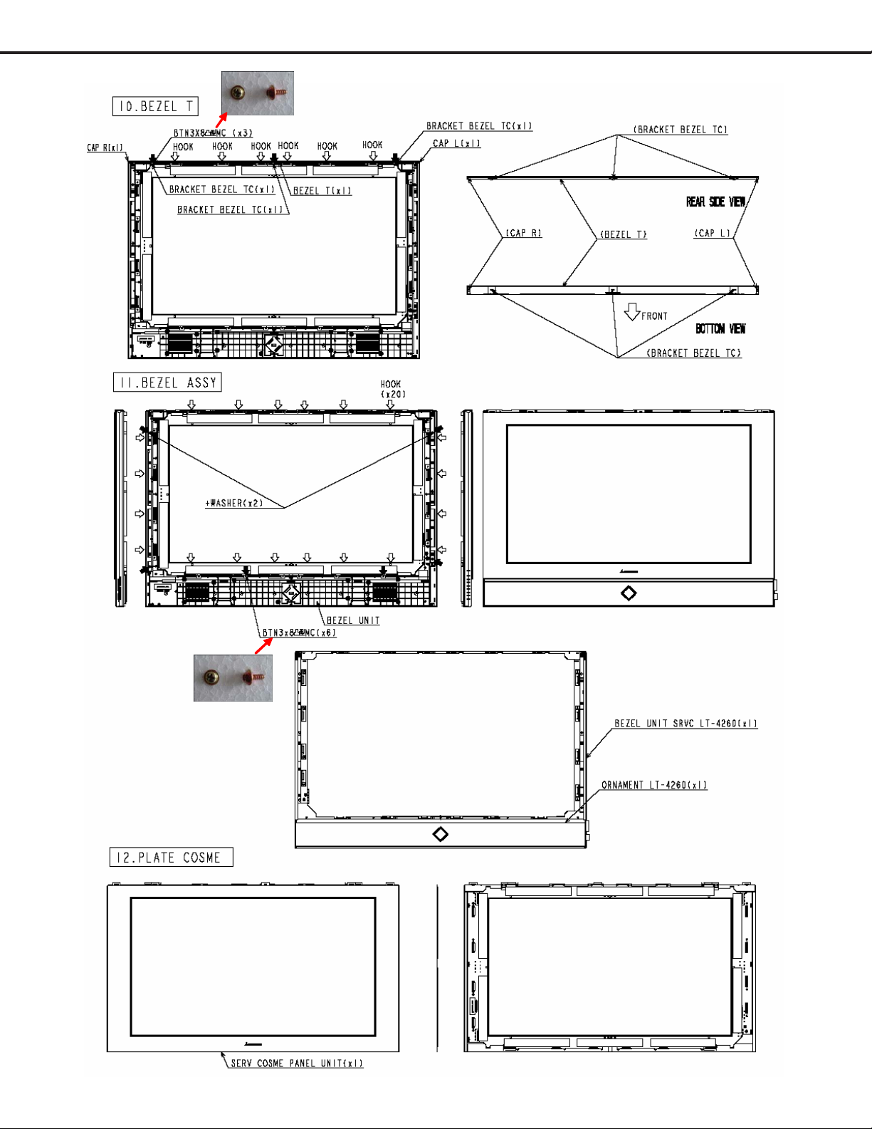
DISASSEMBL Y
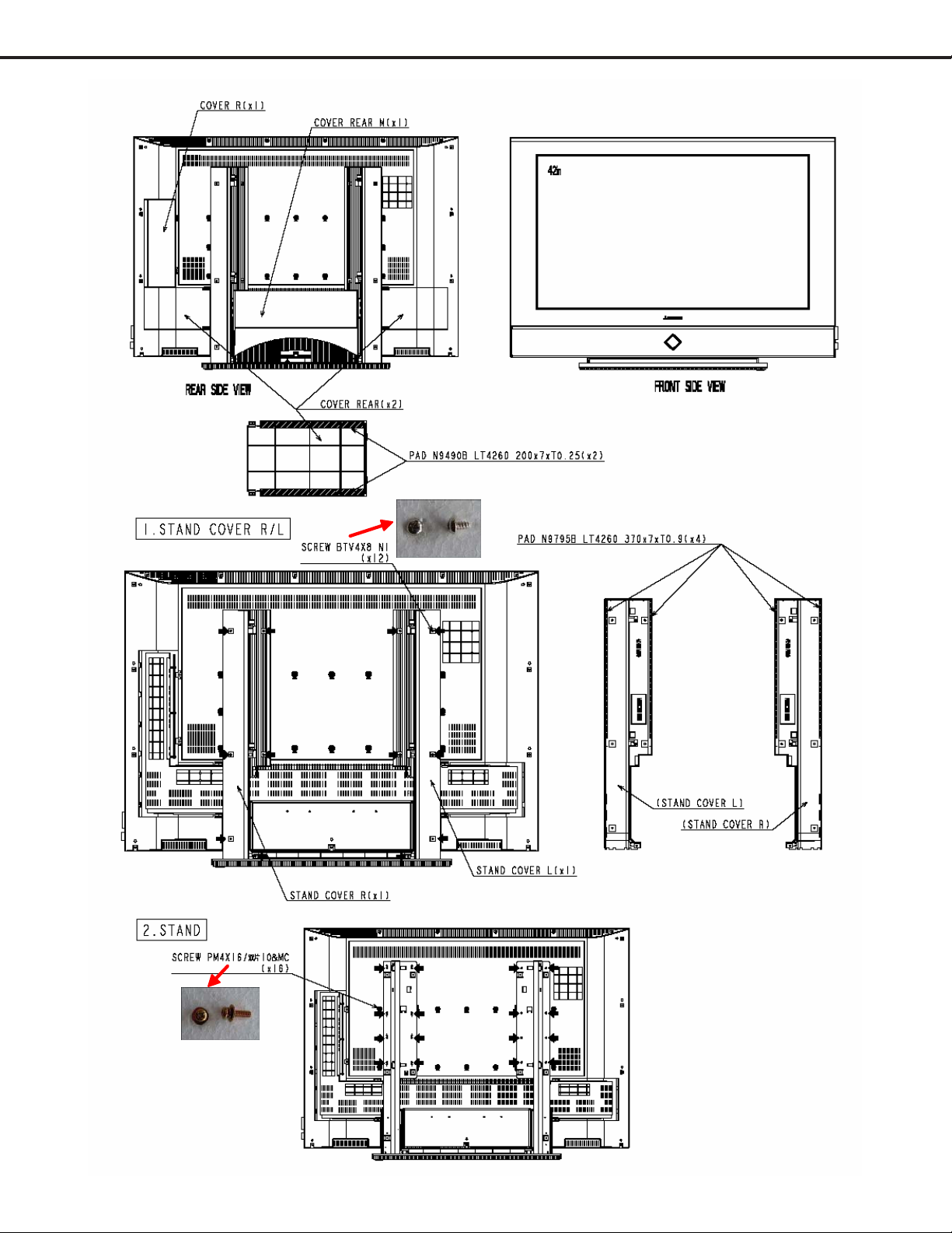
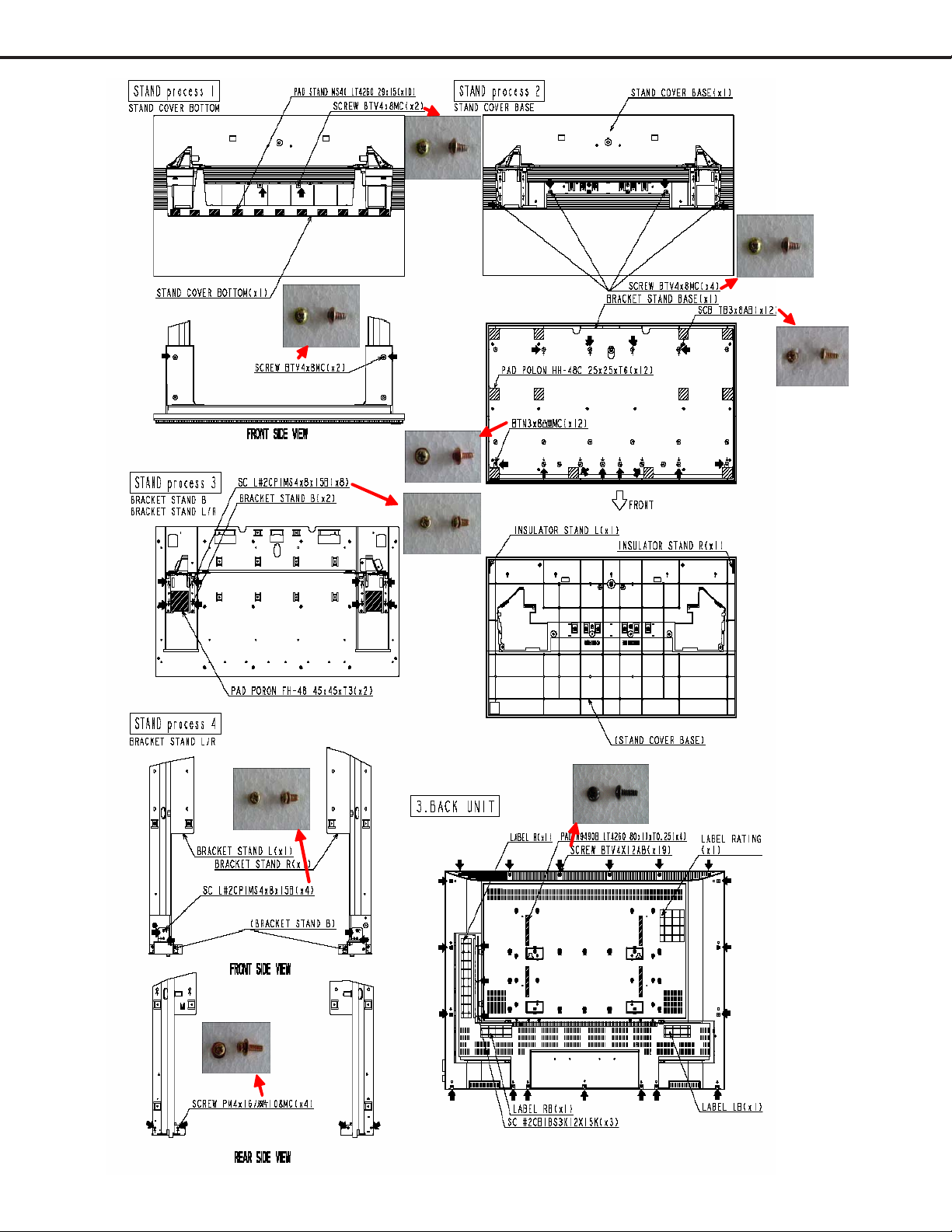
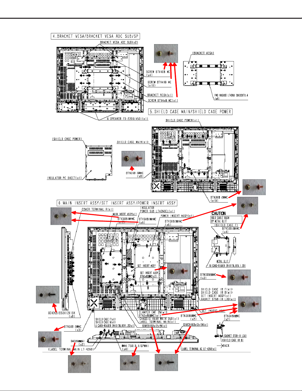
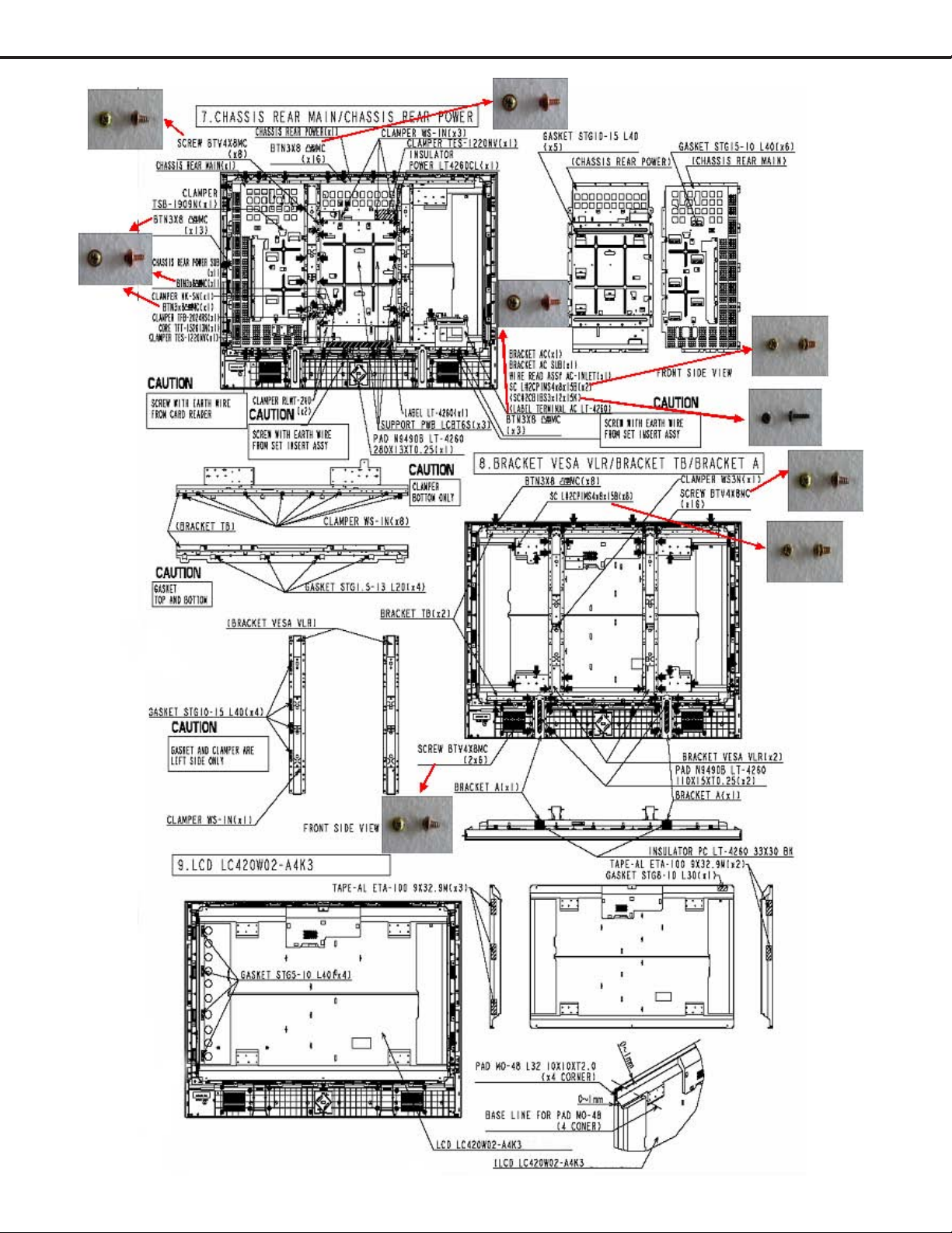
Cabinet Disassembly ......................................................................................................................7
Panel Replacement....................................................................................................................... 13
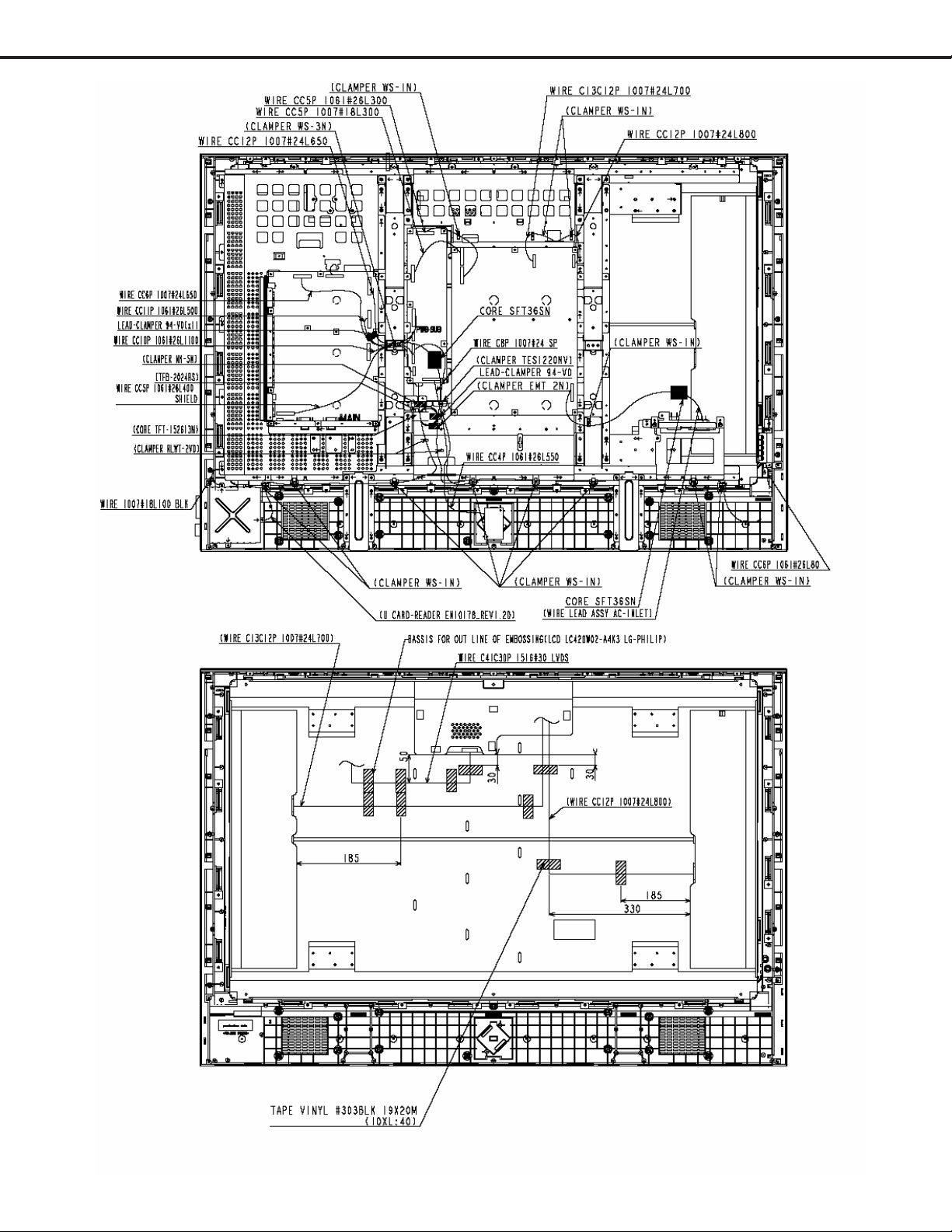
Wire Dressing ............................................................................................................................... 18
ELECTRICAL ADJUSTMENTS
Initial Setup...................................................................................................................................19
CIRCUIT EXPLANA TIONS & BLOCK DIAGRAMS
Circuit Explanations......................................................................................................................20
Block Diagrams ............................................................................................................................ 25
TROUBLESHOOTING
Power Troubleshooting .................................................................................................................. 29
Video Troubleshooting................................................................................................................... 31
Audio Troubleshooting................................................................................................................... 34
Remote Control & Front Switch Troubleshooting ........................................................................... 36
REPLACEMENT P ARTS
Replacement Parts List ................................................................................................................37
SCHEMA TICS
Page 3

MODEL: L423FR
Page 4

MODEL: L423FR
PRODUCT SAFETY NOTICE
Many electrical and mechanical parts in television receivers have special safety related characteristics. These characteristics are often not evident from visual inspection nor can the protection afforded by them necessarily be obtained by
using replacement components rated for higher voltage, wattage, etc.
Replacement parts which have special safety characteristics are identified in this service manual.
The replacement for any safety part should be identical in value and characteristics.
SAFETY PRECAUTIONS
NOTICE: Observe all cautions and safety related notes located inside the receiver cabinet and on the
receiver chassis.
WARNING:
1. Operation of this receiver outside the cabinet or with the cover removed presents a shock hazard
from the receiver's power supplies. Work on the receiver should not be attempted by anyone who is
not thoroughly familiar with the precautions necessary when working on high voltage equipment.
2. Do not install, remove or handle the LCD panel in any manner unless shatterproof goggles are
worn. People not so equipped should be kept away while the panel is being handled. Keep
the panel away from the body while handling.
3. When service is required, observe the original lead dress. Where a short-circuit has occurred, replace
those components that indicate evidence of overheating.
Leakage current check
Before returning the receiver to the customer, leakage current should be measured using following methods.
1. Cold Check
With the alternating current (AC) plug removed from the AC source, place a jumper across the two AC plug prongs.
Connect one lead of an ohm meter to the AC plug and touch the other lead to each exposed met al part (i.e. antennas, handle bracket, metal cabinet, screw heads, metal overlay , control shafts, etc.), p articularly any exposed metal
part that has a return path to the chassis. The resistance of the exposed metal parts having a return path to the
chassis should be a minimum of 1Meg Ohm. Any resistance below this value indicates an abnormal condition
and requires corrective action.
2. Hot Check ...Use the circuit shown below to perform the hot check test.
1. Keep switch S1 open and connect the receiver to the measuring circuit. Immediately after
connection, and with the switching devices of the receiver in their operating positions, measure
the leakage current for both positions of switch S2.
2. Close switch S1, energizing the receiver . Immediately after closing switch S1, and with the
switching devices of the receiver in their operating positions, measure the leakage current for both
positions of switch S2. Repeat the current measurements of items 1 and 2 after the receiver has
reached thermal stabilization. The leakage current must not exceed 0.5 milliampere (mA).
Page 5

MODEL: L423FR
Page 6
MODEL: L423FR
Cabinet Disassembly
Page 7
MODEL: L423FR
Page 8
MODEL: L423FR
Page 9
MODEL: L423FR
Page 10
MODEL: L423FR
Page 11
MODEL: L423FR
Page 12
MODEL: L423FR
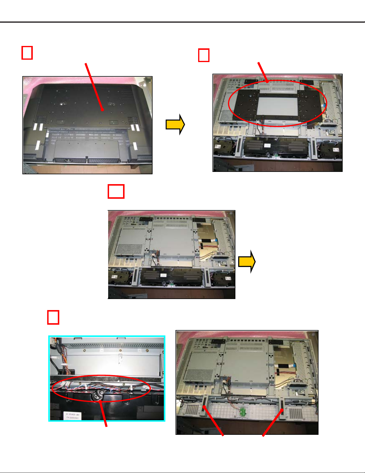
LCD Panel Repl acem ent Procedure
1
Remove back_cover
2
Remove Bracket_Vesa
3
4
Remove MAIN-SP(L/R), & SUB-WOOFER
Remove Sp-connector
Remove BRACKET A
Page 13
MODEL: L423FR
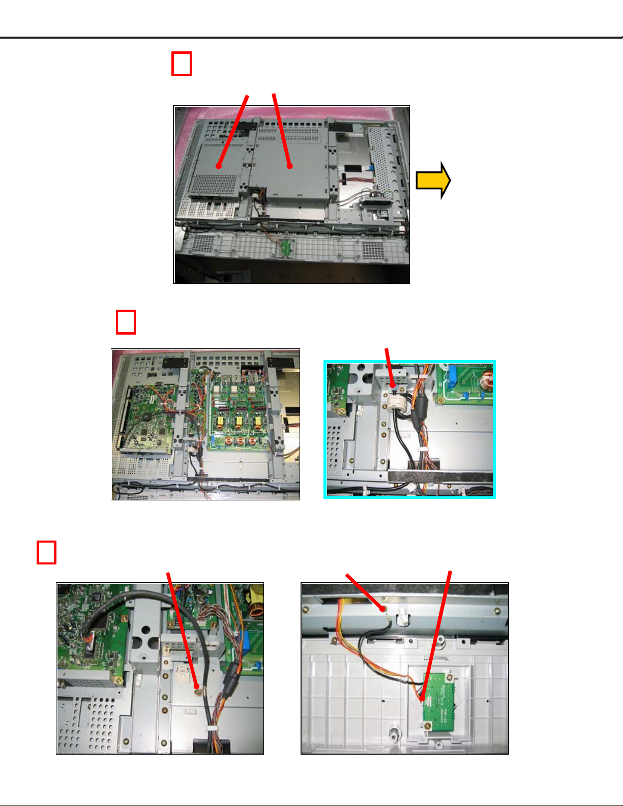
5
Remove SHIELD CASE POWER,MAIN
6
Remove connector of card_reader
7
Remove screw
Remove screw
Remove PWB-LED coonector
Page 14
MODEL: L423FR
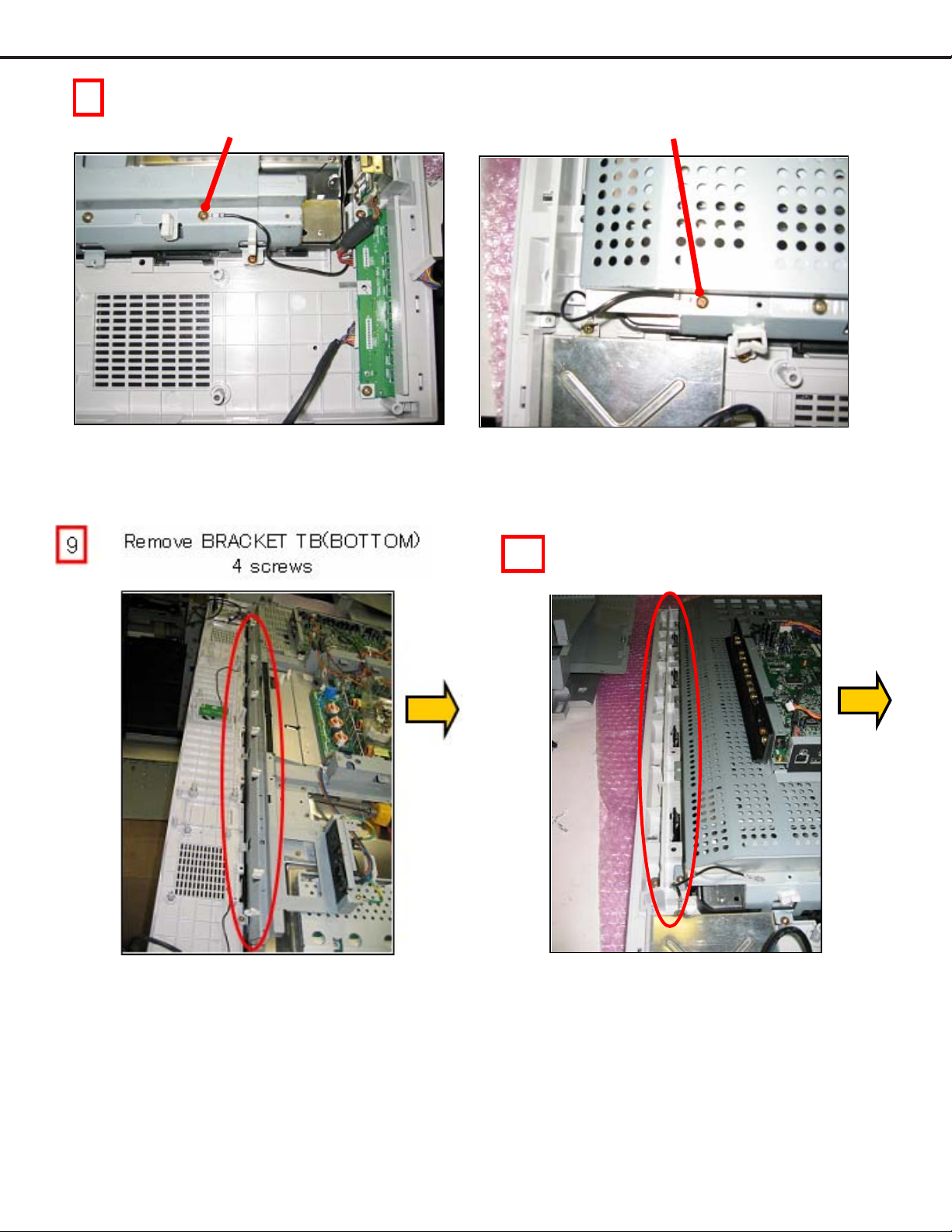
8
Remove screw of earth-lead Remove screw of earth-lead of card reader
10
Remove CHASSIS REAR MAIN
3 screws
Page 15
MODEL: L423FR
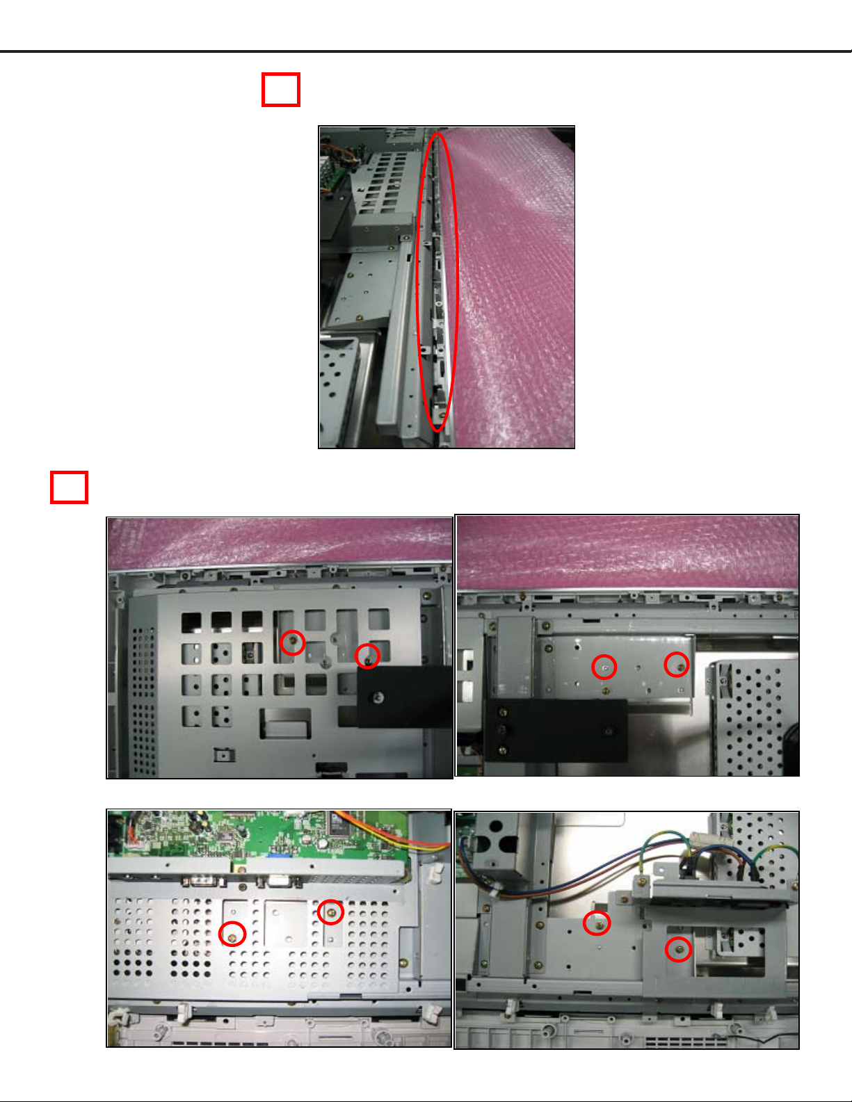
12
11
Remove BRACKET TB(TOP)
4 screws
Remove screws of BRACKET_TB_PANEL
Top-rightTop-left
Bottom-left
Bottom-right
Page 16
MODEL: L423FR
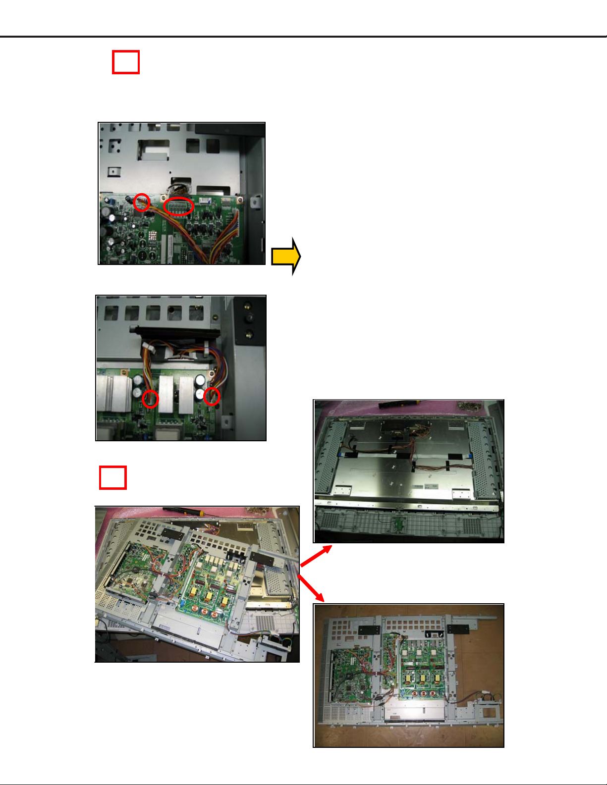
13
Remove connector of PWB-MAIN
LVDS & earth-lead
Remove connector of PWB-power
14
Remove LCD panel
Page 17
 Loading...