

Page 1
20052005
2005
20052005
SerSer
Ser
SerSer
vicevice
vice
vicevice
MITSUBISHI ELECTRIC
ManualManual
Manual
ManualManual
LIQUID CRYST AL DISPLA Y TELEVISION
LT-3280 (LT-3280D)
LT-3780 (LT-3780D)
The LT -3280 includes the L T -3280D, monitor and HD-4001, receiver/controller.
The LT -3780 includes the L T -3780D, monitor and HD-4001, receiver/controller.
This manual covers the L T-3280D and L T -3780D, monitors.
For the receiver/controller, see the HD-4001 Service Manual.
CAUTION:
Before servicing this chassis, it is important that the service person read the "SAFETY PRECAUTIONS" and
"PRODUCT SAFETY NOTICE" contained in this manual.
SPECIFICATIONS
• Power : AC 120V , 60Hz
[LT-3280D] 200W
[LT-3780D] 300W
Standby <5W
• LCD Panel : Size/Resolution [LT-3280D] 32" diagonal, 16:9 / 1366x768
[LT-3780D] 37" diagonal, 16:9 / 1920x1080
: Pixel Pitch -
[LT-3280D] 0.519mm x 0.173mm x RGB
[LT-3780D] 0.4275mm x 0.1425mm x RGB
• Input Jacks : MonitorLink™ Audio/Video - HDMI™
: MonitorLink™ Control - RS-232C
: PC Video - VGA /Mini D-sub 15 pin
: PC Audio - 3.5mm Mini-Jack
• Speakers : 2 Way Bass Reflex Left & Right (2 X 5W)
•
Cabinet Dimensions / We ight
LT-3280D
W i th Stand: Height Width Depth Weight
25.4" 32.4 " 12.8" 68. 0 lbs
W / O S t an d: Height W id th Dept h Wei ght
22.9" 32.4 " 5.0" 44.3 lbs
LT-3780D
W i th Stand: Height Width Depth Weight
28.5" 37.3 " 12 .8" 8 0.0 lbs
W / O S t an d: Height W id th Dept h Wei ght
26.0" 37.3 " 5.3" 57.3 lbs
• Weight and dimensions shown are approximate.
• Design specifications are subject to change without notice.
• HDMI™ is a trademark of HDMI Licensing, LLC
MITSUBISHI DIGITAL ELECTRONICS AMERICA, INC.
9351 Jeronimo Road, Irvine, CA 92618-1904
Copyright © 2005 Mitsubishi Digital Electronics America, Inc.
All Rights Reserved
Page 2

Page 3

MODELS: LT-3280D/LT-3780D
CONTENTS
PRODUCT SAFETY NOTICE & SAFETY PRECAUTIONS..................................................................5
DISASSEMBL Y
Disassembly & Panel Replacement ................................................................................................7
L T-3280 Wire Dressing .................................................................................................................. 23
L T-3780 Wire Dressing .................................................................................................................. 24
ELECTRICAL ADJUSTMENTS
Initial Setup................................................................................................................................... 25
CIRCUIT EXPLANA TIONS & BLOCK DIAGRAMS
Circuit Explanations...................................................................................................................... 27
Block Diagrams ............................................................................................................................32
TROUBLESHOOTING
Power Troubleshooting ..................................................................................................................35
Video Troubleshooting................................................................................................................... 38
Audio Troubleshooting................................................................................................................... 40
Remote Control Troubleshooting ................................................................................................... 42
Front Switch Troubleshooting........................................................................................................ 43
REPLACEMENT P ARTS
L T-3280 Replacement Parts List.................................................................................................... 44
L T-3780 Replacement Parts List.................................................................................................... 45
SCHEMA TICS
Page 3
Page 4

MODELS: LT-3280D/LT-3780D
Page 4
Page 5
MODELS: LT-3280D/LT-3780D
PRODUCT SAFETY NOTICE
Many electrical and mechanical parts in television receivers have special safety related characteristics. These characteristics are often not evident from visual inspection nor can the protection afforded by them necessarily be obtained by
using replacement components rated for higher voltage, wattage, etc.
Replacement parts which have special safety characteristics are identified in this service manual.
The replacement for any safety part should be identical in value and characteristics.
SAFETY PRECAUTIONS
NOTICE: Observe all cautions and safety related notes located inside the receiver cabinet and on the
receiver chassis.
WARNING:
1. Operation of this receiver outside the cabinet or with the cover removed presents a shock hazard
from the receiver's power supplies. Work on the receiver should not be attempted by anyone who is
not thoroughly familiar with the precautions necessary when working on high voltage equipment.
2. Do not install, remove or handle the LCD panel in any manner unless shatterproof goggles are
worn. People not so equipped should be kept away while the panel is being handled. Keep
the panel away from the body while handling.
3. When service is required, observe the original lead dress. Where a short-circuit has occurred, replace
those components that indicate evidence of overheating.
Leakage current check
Before returning the receiver to the customer, leakage current should be measured using following methods.
1. Cold Check
With the alternating current (AC) plug removed from the AC source, place a jumper across the two AC plug prongs.
Connect one lead of an ohm meter to the AC plug and touch the other lead to each exposed met al part (i.e. antennas, handle bracket, metal cabinet, screw heads, metal overlay , control shafts, etc.), p articularly any exposed metal
part that has a return path to the chassis. The resistance of the exposed metal parts having a return path to the
chassis should be a minimum of 1Meg Ohm. Any resistance below this value indicates an abnormal condition
and requires corrective action.
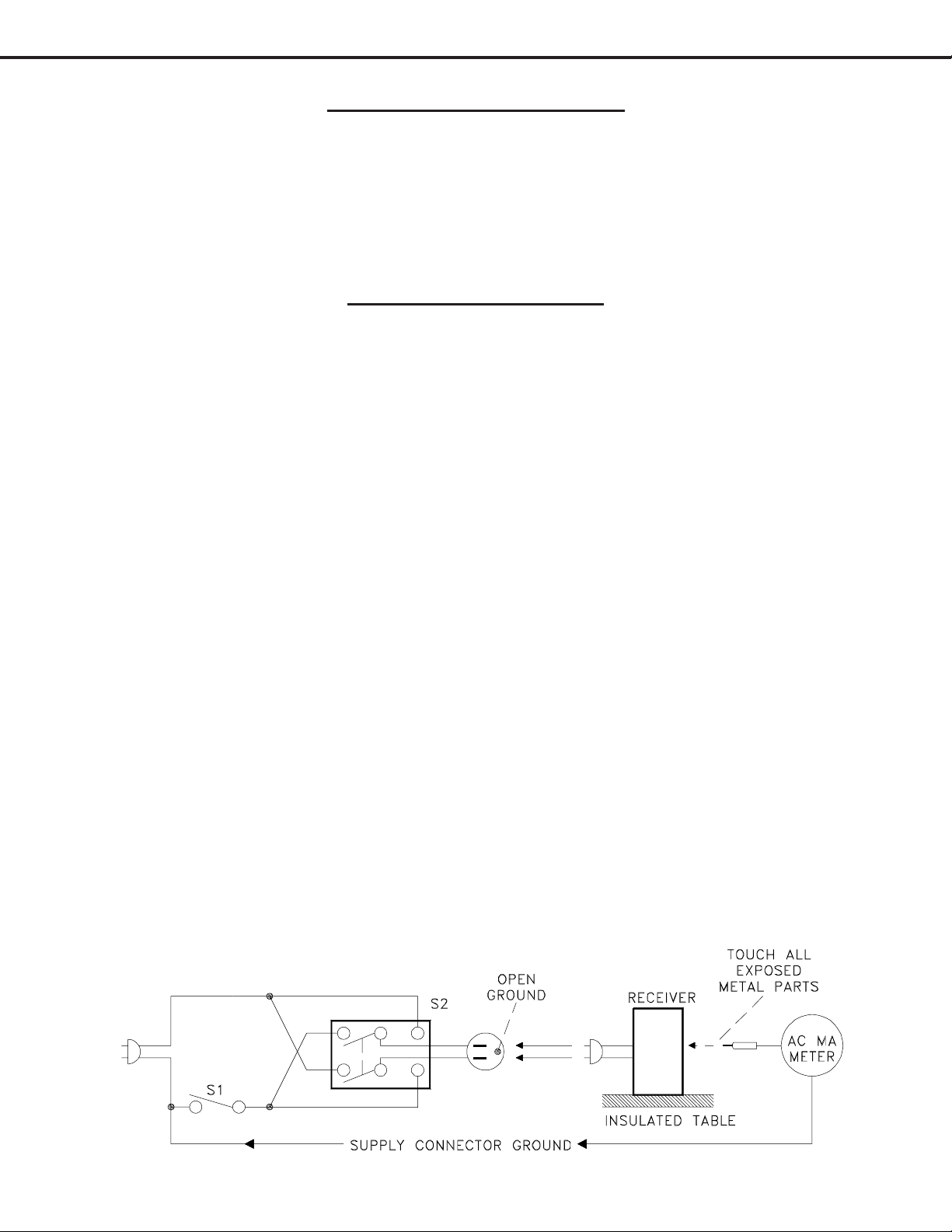
2. Hot Check ...Use the circuit shown below to perform the hot check test.
1. Keep switch S1 open and connect the receiver to the measuring circuit. Immediately after
connection, and with the switching devices of the receiver in their operating positions, measure
the leakage current for both positions of switch S2.
2. Close switch S1, energizing the receiver . Immediately after closing switch S1, and with the
switching devices of the receiver in their operating positions, measure the leakage current for both
positions of switch S2. Repeat the current measurements of items 1 and 2 after the receiver has
reached thermal stabilization. The leakage current must not exceed 0.5 milliampere (mA).
Page 5
Page 6

MODELS: LT-3280D/LT-3780D
Page 6
Page 7
MODELS: LT-3280D/LT-3780D
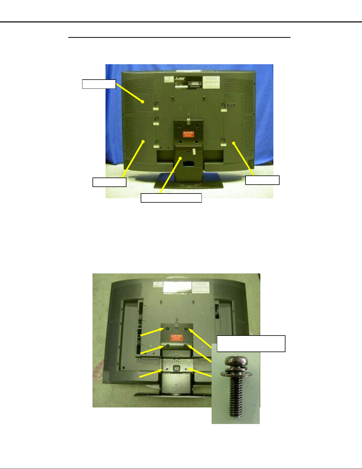
DISASSEMBLY & PANEL REPLACEMENT PROCEDURE
1. REMOVE AV1, A V2, DTV & STAND COVERS.
AV1-COVER
AV2-COVER
STAND-FRAME-COVER
DTV-COVER
2. PLACE SET F ACE DOWN ON A SOFT CUSHION, WITH THE ST AND HANGING OVER THE
EDGE OF THE TABLE.
3. REMOVE ST AND-KIT .
S20:SCREW PH+SW+W
M6*21.5
Page 7
Page 8
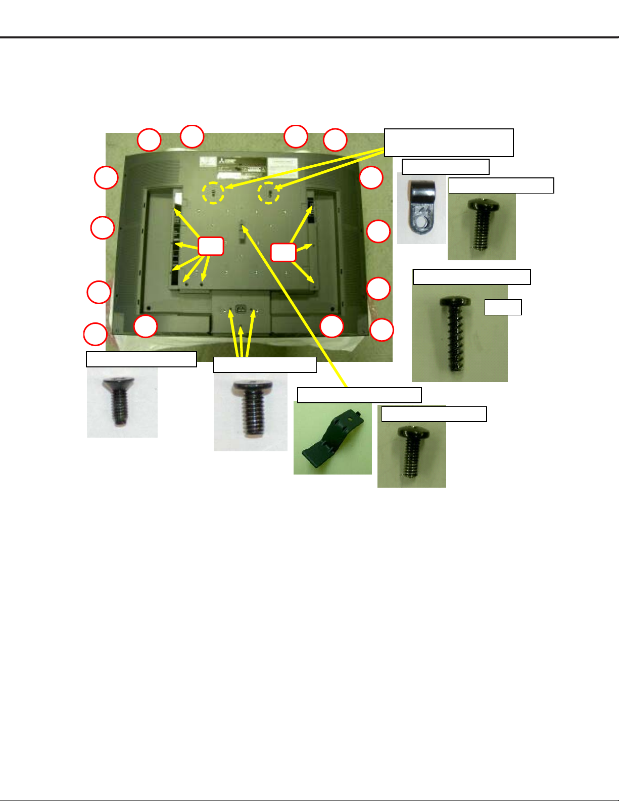
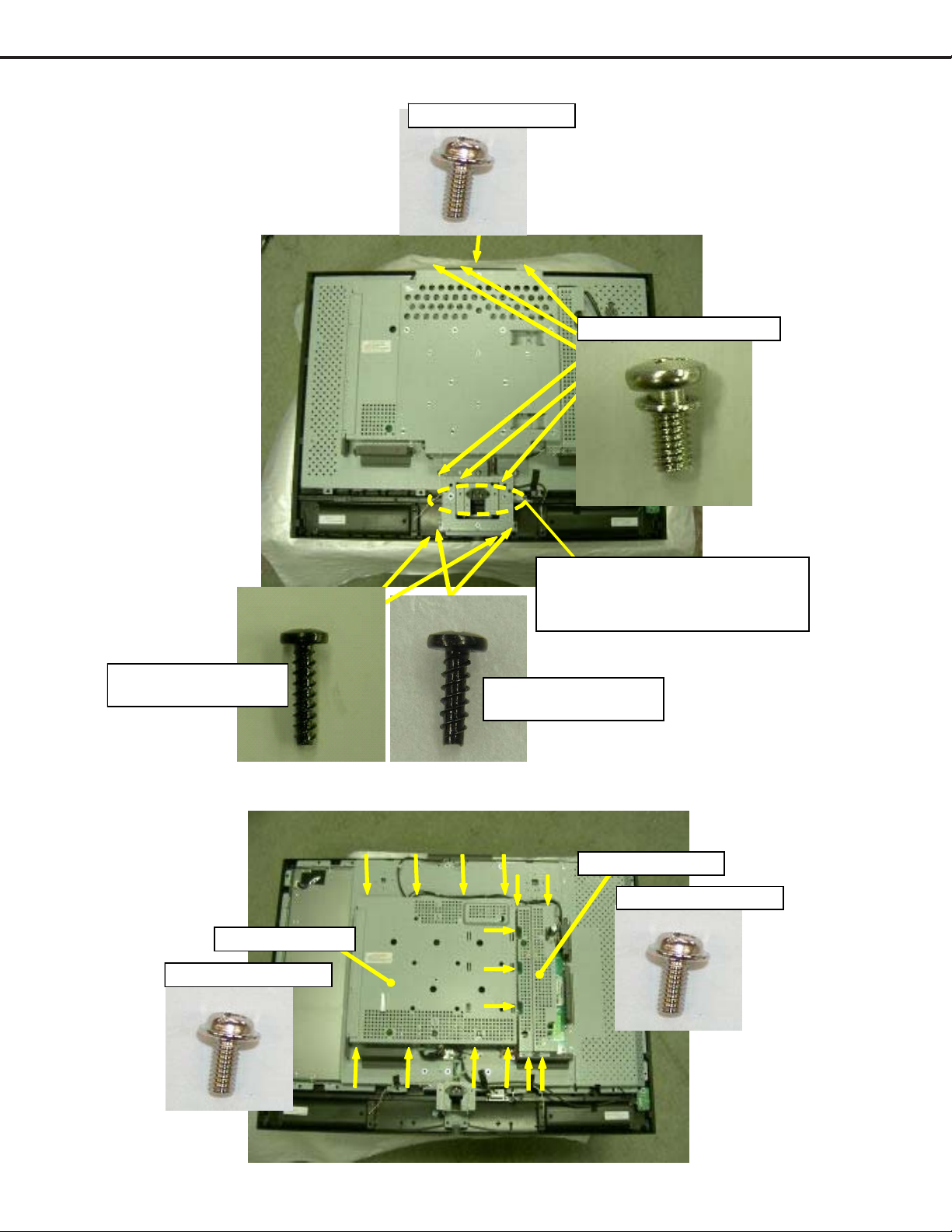
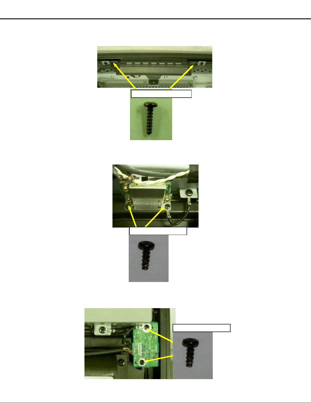
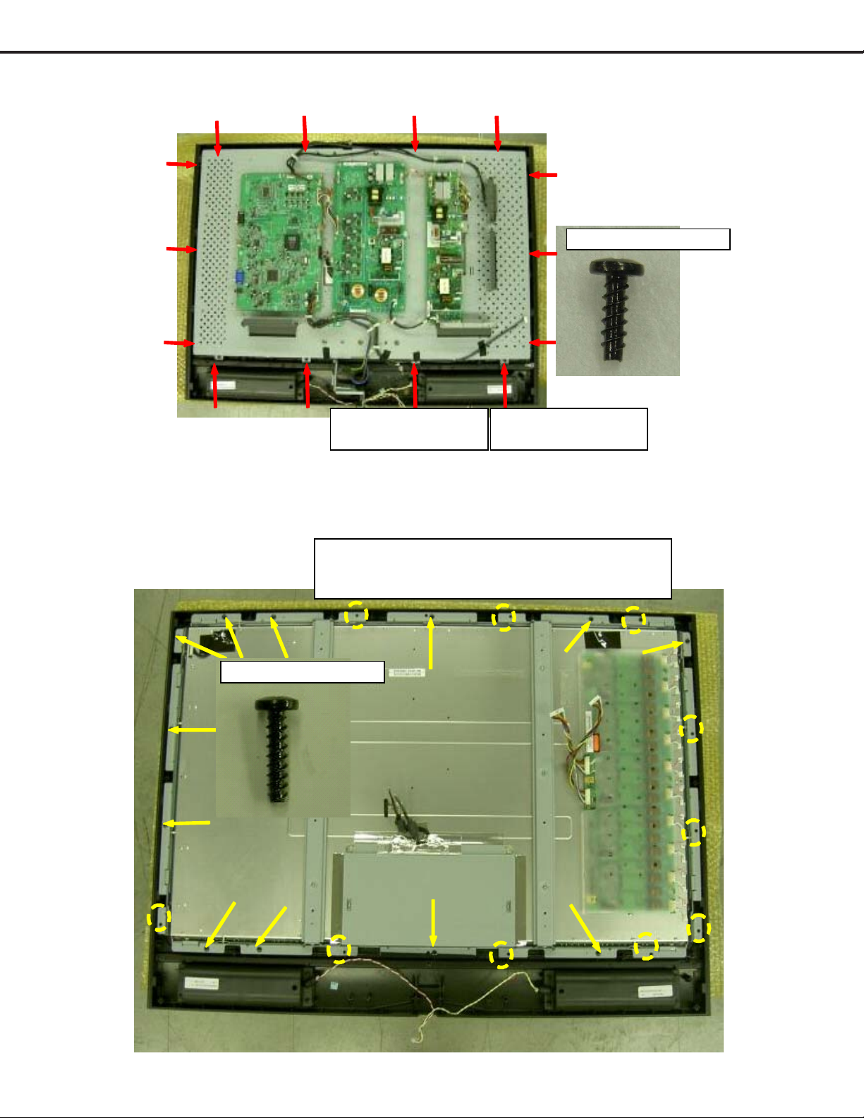
4. REMOVE BACK COVER KIT .
MODELS: LT-3280D/LT-3780D
S5
S5
S5
S5 S5
S5
S14:SCREW FPH M 3*8
S5
S14
S10:SCREW IH M4*8
S5
S14
S5S5
SCREW WIT H ST AY -STAND
SCERW WIT H CABL E -CL AM P
2 POINTS
F07:CABLE-CLAMP
S5
S5
S5:SCREW BH 4*16TP-P
S5
S5
S3:SCREW BH M 4*10
S3:SCREW BH M4*10
14 PCS
Page 8
Page 9
MODELS: LT-3280D/LT-3780D
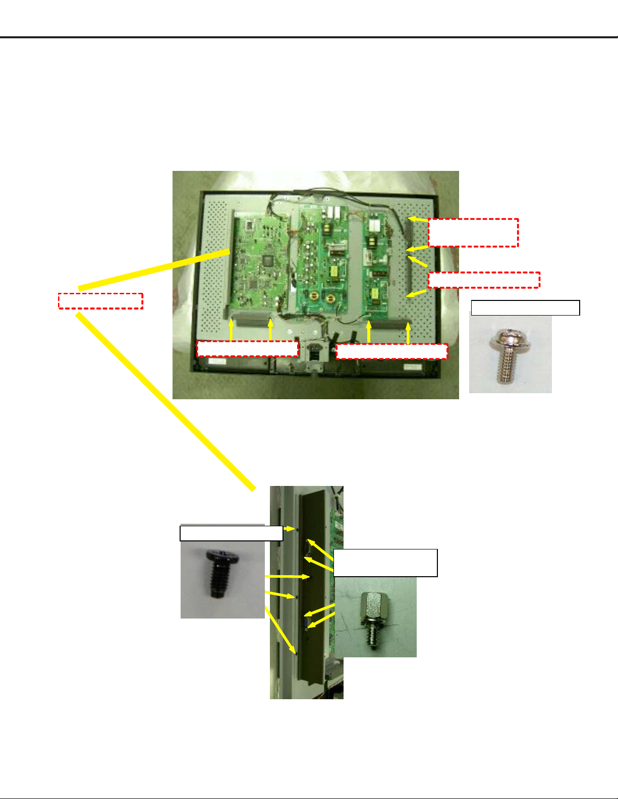
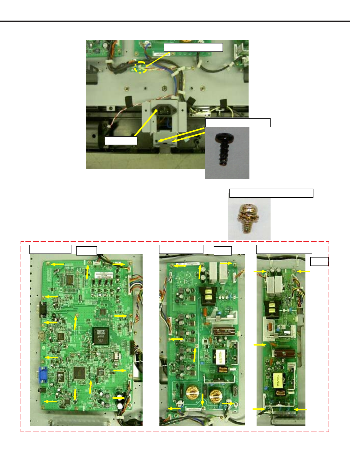
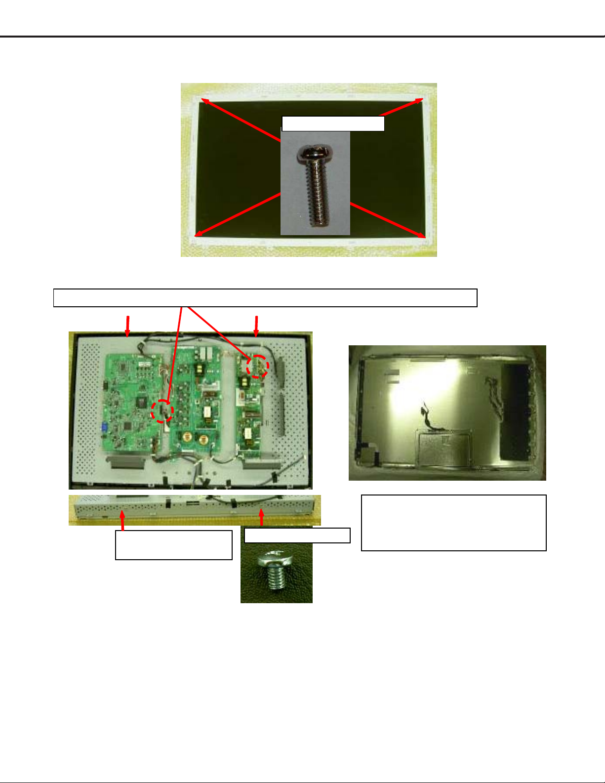
5. REMOVE WALL MOUNT BRACKET
S9:SCREW PH W M 3*6
S16:SCREW B H +SW M6* 12
REM OVE WAL L-M OU N T-BK T ,
WHILE DEPRESSING THE HAN GING
PART OF P OWER- B KT BE L O W.
LT-3780D
S5:SCREW BH 4*16TP-P
LT-3280D
S8:SCREW BH 4*12TP-P
6. REMOVE SHIELD-POWER-SUB & SHIELD-CASEMAIN.
SHIELD-CASE-MAIN
S9:SCREW PH W M 3 *6
SHIELD-POWER-SUB
S9:SCREW PHW M3*6
Page 9
Page 10
MODELS: LT-3280D/LT-3780D
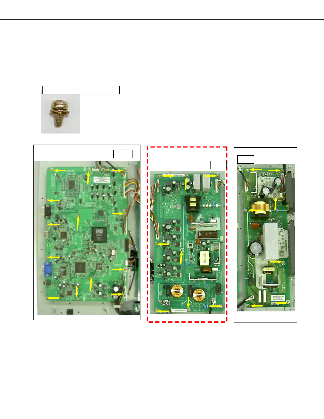
7A. (L T -3280D)
(NOT NECESSARY FOR P ANEL REPLACEMENT)
REMOVE:
a. PLA TE-MAIN-SIDE
b. SERVICE-KIT
c. PLA TE-MAIN-BOTTOM
d. PLA TE-POWER-BOTTOM
SERVICE-KIT
(SA-PWB-SERV ICE)
PLATE-POWER-BOTTOM
PLATE-MAIN-SIDE
PLATE-MAIN-BOTTOM
S11:SCREW IH M3*6
S9:SCREW PH W M 3 *6
PLATE-POWER-BOTTOM
S15:SCREW_HH+SW
_UNC4#-40*7_H5
Page 10
Page 11
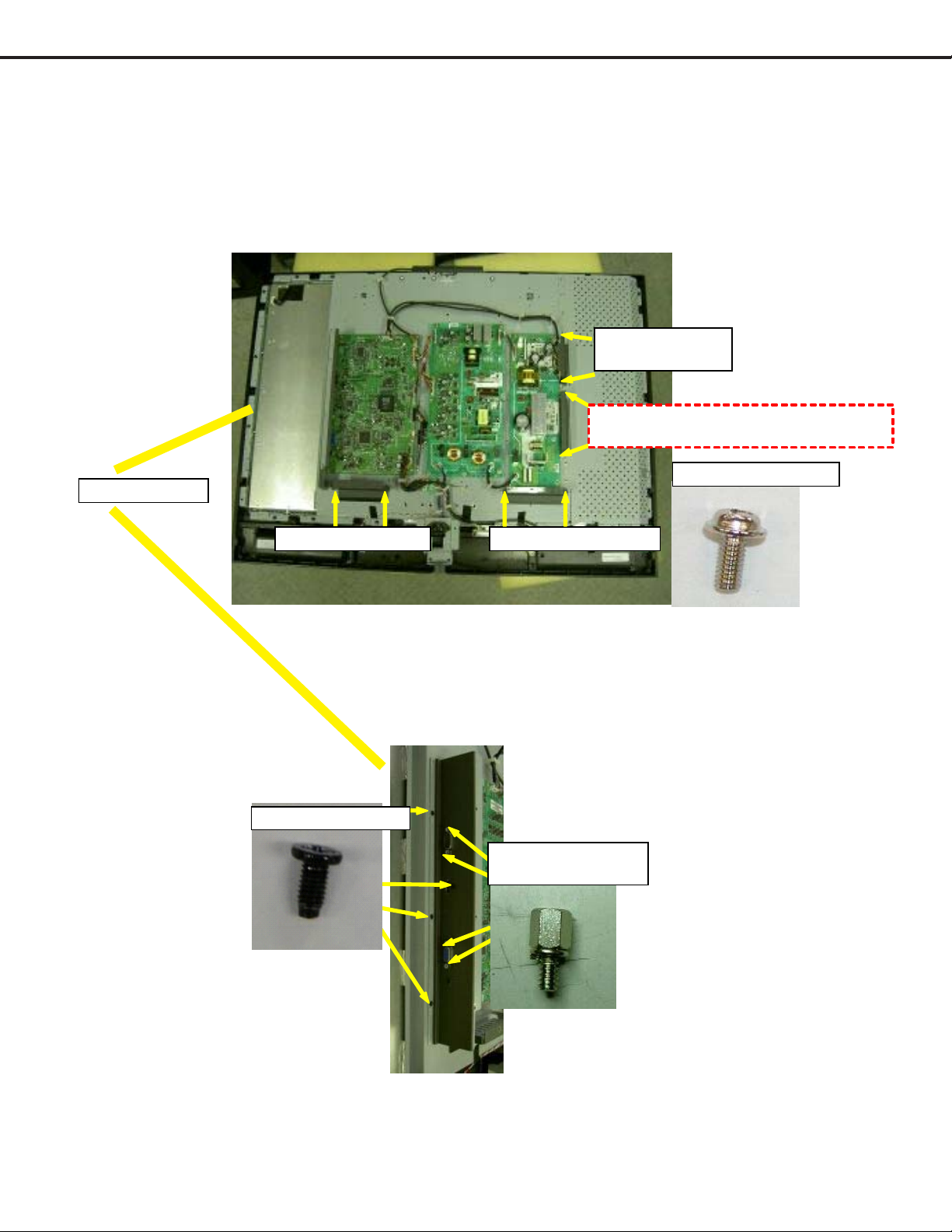
7B. (L T-3780D) REMOVE:
a. PLA TE-MAIN-SIDE
b. SERVICE-KIT
c. PLA TE-MAIN-BOTTOM
d. (NOT NECESSARY FOR
P ANEL REPLACEMENT)
PLATE-POWER-BOTTOM
PLATE-MAIN-SIDE
MODELS: LT-3280D/LT-3780D
SERVICE-K IT
(SA-PWB -SERVICE)
PLATE-POWER-BOTTOM
NOT NECESSARY FOR PANEL REPLACEMENT
S9:SCREW PH W M 3 *6
PLATE-MAIN-B OTTOM
S11:SCREW IH M3*6
PLATE-POWER-BOTTOM
S15:SCREW_HH+SW
_UNC4#-40*7_H5
Page 11
Page 12
MODELS: LT-3280D/LT-3780D
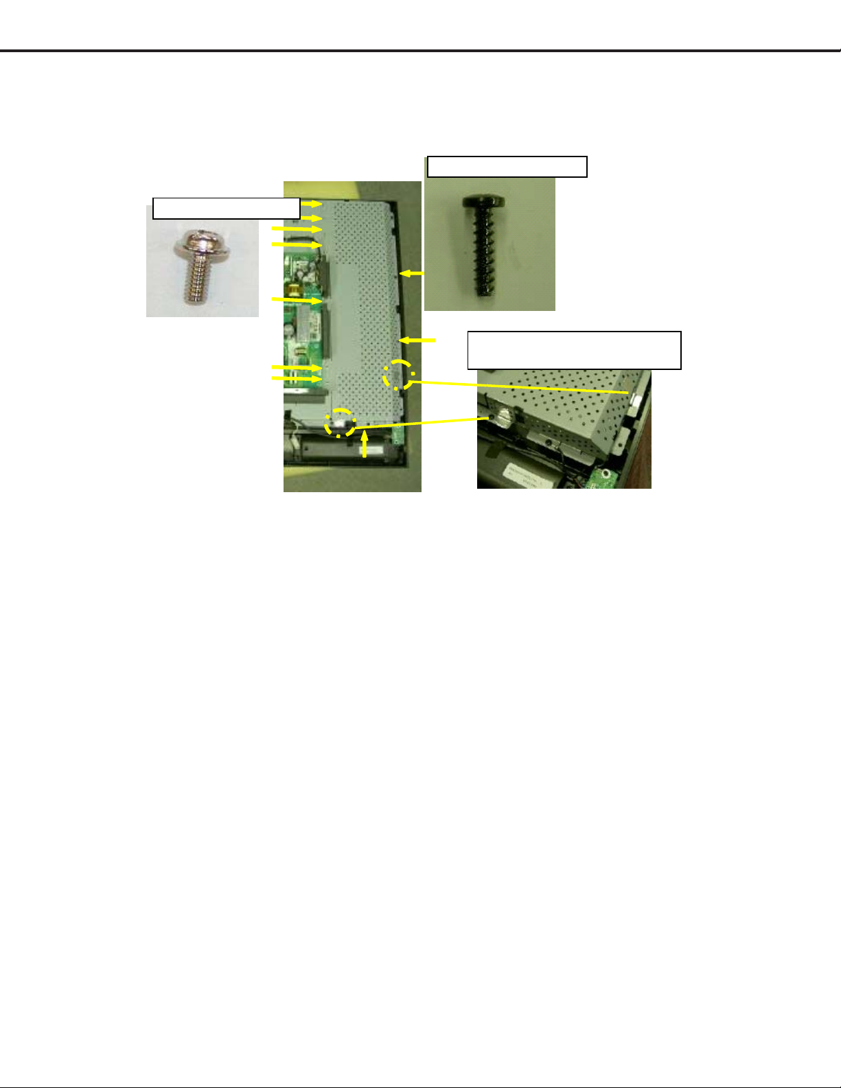
8. (L T-3780D ONL Y) REMOVE SHIELD-INVERTER
S9:SCREW PH W M 3*6
S5:SCREW BH 4*16TP-P
ITEM 144: AL-TAPE
It sti ck s on the position of a fig ure.
Page 12
Page 13
9. REMOVE FUNCTION-KEY -KIT
10. REMOVE IR-KIT
MODELS: LT-3280D/LT-3780D
S6:SCREW BH 3*12 TP-P
11. REMOVE SA-PWB-LED
S4:SCREW BH 3*8 TP-P
S4:SCREW BH 3*8 TP-P
Page 13
Page 14
MODELS: LT-3280D/LT-3780D
12. REMOVE POWER-KIT & SPEAKER CONNECTOR
SPEAKER-CONNECTER
POWER-KIT
S4:SCREW BH 3*8 TP-P
13A. (L T -3280D)
S17:SCREW PH +SW+ T W M 3 *6
(NOT NECESSARY FOR P ANEL REPLACEMENT)
REMOVE:
a. A-PWB-MAIN 2
b. SA-PWB-POWER
c. A-PWB-POWER-SUB2
A-PWB-MAIN_2 SA-PWB-POWER A-PWB-POWE R-SUB 2
13 PCS 8 PCS
5 PCS
Page 14
Page 15
13B. (L T -3780D)
REMOVE:
a. A-PWB-MAIN 2
b. SA-PWB-POWER
c. A-PWB-POWER-SUB2
S17:SCREW PH +SW+ T W M 3 *6
MODELS: LT-3280D/LT-3780D
(NOT NECESSARY FOR PANEL REPLACEMENT)
A-PWB-MAIN_1
13 PCS
SA-PWB-POWER
NOT NE CE SSA RY FOR P ANEL
REPLACEMENT
8 PCS
A-PWB-POW ER-SUB1
7 PCS
Page 15
Page 16
MODELS: LT-3280D/LT-3780D
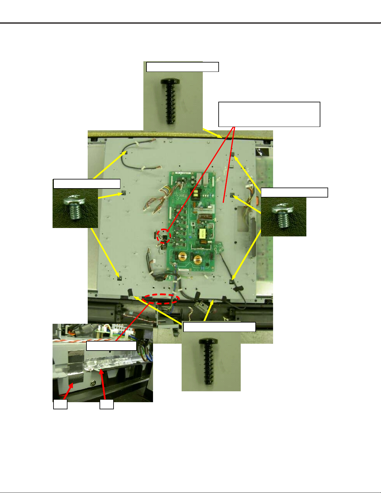
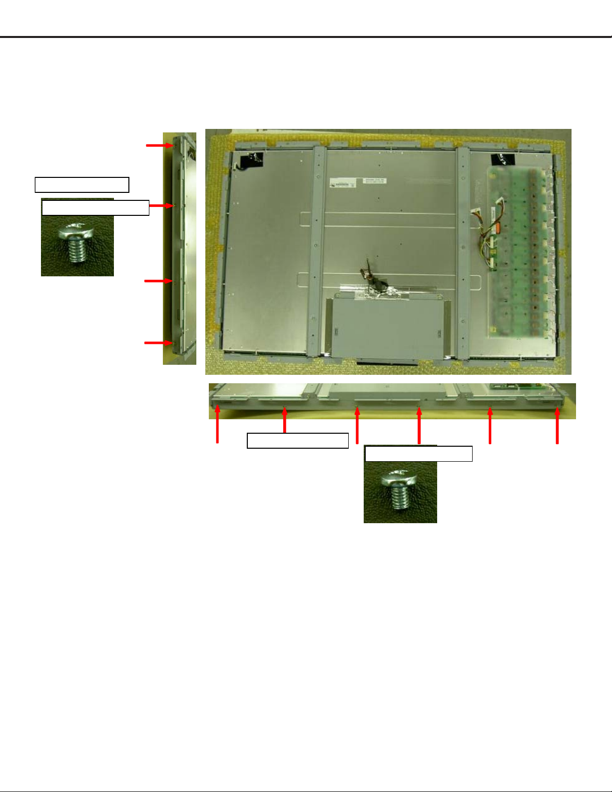
14. (L T -3780D) REMOVE P ANEL_BKT
S5:SCREW BH 4*16TP-P
S2:SCREW BH M4*5.5
RE MOVE CNF1/CNF2/ CN 1/CN2-L EAD
to the panel side not to be caught
by PANEL -B K T.
S2:SCREW BH M 4*5.5
AT TACH AL -TAP E
144 143
S5:SCREW BH 4*16TP-P
Page 16
Page 17
MODELS: LT-3280D/LT-3780D
15A. (L T -3280D) REMOVE FRONT -KIT & SPEAKER
S8:SCREW BH 4*12TP-P
Screw with GND-W ire
(50mm).
15B. (L T -3780D) REMOVE FRONT -KIT & SPEAKER
CAUTION:
UP AN D DOWN DIRECTION OF PANE L IS AGAINST
LABEL AND ARROW MARK OF PANEL.
S5:SCREW BH 4*16TP-P
Screw with GND-Wire
(90mm).
Page 17
Page 18
MODELS: LT-3280D/LT-3780D
16. (L T-3280D) REMOVE P ANEL_BKT
S1:SCREW PH M4*12
REMOVE CNF1/CN1/CN2-LEAD first and push in under PANEL-BKT for easy removal.
Top & Bottom is same.
4 PCS (2x2)
S2:SCREW BH M4*5.5
17. (LT-3280D)
FOR RE-ASSEMBL Y AFTER P ANEL REPLACEMENT,
REVERSE THE DISASSEMBL Y PROCEDURE.
CONTINUE FOR L T -3780D PANEL REPLACEMENT AND
FURTHER DISASSEMBL Y INSTRUCTIONS.
Page 18
CAUTION:
UP AND D OW N DIRECTION OF
PANEL IS AGAINST LABEL AND
A RROW MARK OF PANEL.
Page 19
MODELS: LT-3280D/LT-3780D
18. (L T-3780D) REMOVE SUPPOR T-P ANEL-BKT -RIGHT , LEFT, TOP, BOT TOM
Left & Right is same.
S2:SCREW BH M4*5.5
Bottom & Top is sam e.
S2:SCREW BH M4*5.5
Page 19
Page 20

MODELS: LT-3280D/LT-3780D
19. (L T-3780D) A TTACH AL-TAPE AT DRIVE-UNIT OF PANEL
250
ITEM 142: AL-TAPE 20X140, 2Q' ty
141
250
ITEM 141: Alumi-tape :20X250, 1Q' ty
Drive-uni t and Panel-outer should be grounded.
ITEM 141: AL-TAPE
20X250 1Q'ty
140
70
140
40
ITEM 144:Alumi-tape 20X
45, 1Q'ty
ITEM 132:Insulati ngtape10X70
Th e el ec trod e of a
connector is insulated.
ITEM 145: Alumi-tap e
40X140, 1Q' ty Shield
with CNF1,CNF2.
20. (LT-3780D)
FOR RE-ASSEMBL Y AFTER P ANEL REPLACEMENT,
REVERSE THE DISASSEMBL Y PROCEDURE.
CONTINUE FOR FURTHER DISASSEMBL Y INSTRUCTIONS
FOR BOTH L T -3280D & L T -3780D.
Page 20
Page 21

MODELS: LT-3280D/LT-3780D
20. REMOVE FUNCTION-KEY -KIT
21. REMOVE IR-KIT
S4:SCREW BH 3*8 TP-P
3 PCS
REVERSE S IDE
SA-PWB-IR
S17:SCREW PH +SW+ T W M 3 *6
3 PCS
SHIELD-IR-TOP SHIELD-IR-BOTTOM
Page 21
Page 22

22. REMOVE SERVICE-KIT
S9:SCREW PH W M 3*6
After th e p ro j e c tion at th e r igh t
of COV ER is inserted in the hole of PLATE,
screw LEFT SID E.
S11:SCREW IH M 3*6
MODELS: LT-3280D/LT-3780D
2 PCS
S15:SCREW_HH +SW
_UNC4#-40*7_H5
COVER-SERVICE
SA-PWB-SERVICE
PLATE-SERVICE
Page 22
Page 23

MODELS: LT-3280D/LT-3780D
T
T
T
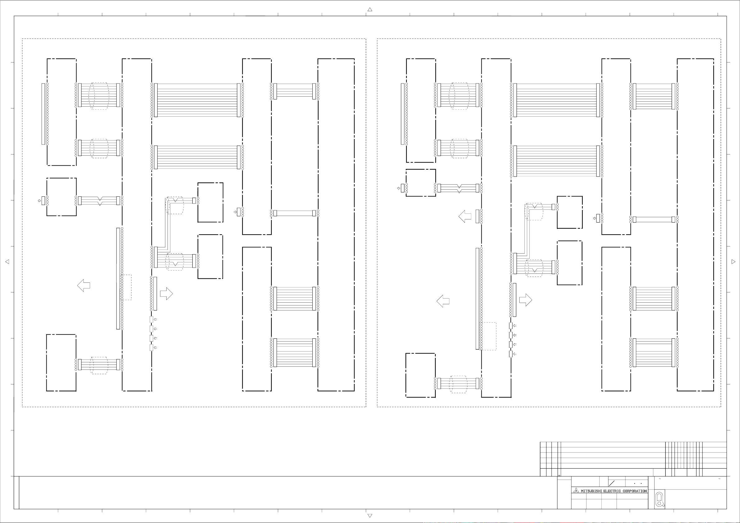
WIRING LAYOUT: LT-3280DD
CN2
CN1
LOWER SIDE OF A-PWB-SUB2
MS1 does not unfasten from HOUSING.
MS2 MS1
F4 F4
SERVICE-KIT
(SA-PWB-SERVICE)
CLAMP MS1/MS2-lead AT SHIELD-CASE-MAIN
F3
F3
PC:
Don't touch RADIATOR
F3
PC
F3
PC
FUNCTION-KEY-KIT
(SA-PWB-CONTROL)
A-PWB-POWER-SUB2
PB
PB
F3
F1
F1
F1
S18:PANEL-GND
ERMINAL OF WIRE-GND SHOULD
ERMINAL-MARK.
BE ATACHED ACCORDING TO PCB
CAUTION:
MB1
GND_WIRE (90mm)
he place which i s not covered with TUBE does not
touc h th e e dge of PLATE-P OWE R -BOTTOM.
#1
MB2
F1
F1
SA-PWB-LED
GND_WIRE (50mm)
IR-KIT
(SA-PWB-IR)
F4
CLAMP MB1/MB2 - lead AT SHI ELD-CASE- MAIN
SPEAKER_L
UPPER: PA-lead
LOWER: SP(R)-lead
When you attach S H I ELD-CASE-M AI N ,
don't damage ski n of MA/M B /PA-lead.
INLET -PA
#1: Wires must be fixed on vertical surface of PANEL-BK T.
MC
F1
ake ca re not to place M C-lead with BACK - C OVER.
CAUTION:
When you atta c h BACK-COVER,
PE
OP:PD
BOTTOM:PE
F3
MC
PD
MS1
MS2
SCREW FOR GND
PD
PE
A-PWB-MAIN_2 A-PWB-POWER
SCREW PH+SW+T W M3*6
:
S17
CNF1
S17:GND
PA
MB
MA
S18:SCREW_PH+SW+W(14)
_M6*10
SCREW FOR PANEL-GND
F1
SP
#1
MA
SA-PWB-CONNECT
F1
SPEAKER_R
CAUTION:
CNF1 W I R I NG
LOWER SIDE OF SA-PWB-POWER
INLET -PA
SP(R)
SP(R)-lead does not approach the
m etal term inal part of I NLET - P A.
Page 23
Page 24

MODELS: LT-3280D/LT-3780D
(
)
T
p
T
p
p
(
)
(
)
WIRING LAYOUT: LT-3780DD
SPEAKER_R
S17:SCREW PH+S W+TW M3*6
SCREW FOR PANEL-G N D
S18:SCREW_PH+SW+W(14)
_M6*10
NOT SCREW
(2 POINT)
CNF1,2 WI RING
SCREW FOR GND; 2 POINT
CAUTION:
When you attach BACK-COVER,
ake c are not to
lace MC-lead wi th BACK -COVER.
CAUTION:
When you attach WALL-MOUNT -BK T,
ake care no t to
CAUTION:
SP( R) -l ea d d oe s no t app ro ac h the
metal terminal part of INLET-PA.
SP(R)
lac e this clam
INLET-PA
er with it.
INLET-PA
#1: Wi res must be fixed on ver ti cal surface of PANEL -BKT.
When you attac h SH I EL D - CASE - M AIN,
don't damage skin of MA/MB/PA-lead.
UPPER: PA-l ead
LOWER: SP
R
-lead
CL AM P M B 1 / M B 2-l e ad AT SHIELD - C AS E -MAIN
SA-PWB-CONNECT
#1
F1 F1
F1
(SA-PWB-IR)
IR-KIT
GND_WIRE
50mm
S18:PANEL-GND
MB2
#1
The pl a ce which is n ot covered with TUBE do es no t
touch the edge of PLAT E- POWE R-B OT T O M.
S17:GND
F1
MA
MB
MA
PA PB
SP
F1
F1
PB
CNF1
CNF2
A-PWB-MAIN_1 A-PWB-POWER
F1
S17:GND
PE
PD
A-PWB-POWER-SUB1
MS2
MS1
PD
MC
F3
UPPER: PD
LOWER: PE
F3
PC
F1
MC
PE
PC
F3
F3
(SA-PWB-SERVICE)
SERVICE-KIT
(SA-PWB-CONTROL)
FUNCTION-KEY-KIT
PC:
Do n 't touc h RADIATOR
SPEAKER_L
GND_WIRE
SA-PWB-LED
MB1
F4
90mm
F10:TWIST-LOCK(A-8)
Clamp it, in order that wire should not touch
CAUTION:
TE RMIN AL OF WIRE-GN D SH OULD
BE ATTACH ED ACCORDING TO PCB
TERMINAL-MARK.
LOWER SIDE OF A-PWB-SUB1
a prim ar y c ircuit
F10
MS1/MS2-lead is hooked on BARRIER-SERVICE.
MS1 does not unfasten from HOUSING.
CL AM P M S 1 /MS2-l e ad AT SHIEL D -C AS E -MAIN
F4
SERVICE-KIT
MS2 MS1
CN1
CN2
Page 24
CN1/CN2
F4
Page 25

MODELS: LT-3280D/LT-3780D
TM
TM
t
r
A
Initial Setup
A. Option Menu Setup
Follow the steps below for the initial set-up:
1. Disconnect the HD-4001.
2. Place the Remote control in the “TV” layer.
3. Select the "MENU" display by pressing the "TV MENU" button once.
4. Press the number buttons "2", "0", "7", "0" in sequence to select the "OPTION MENU" display.
5. Press the "ADJUSTST" buttons to select "INITIALIZE."
6. Press "ENTER."
<MENU><2-0-7-0>
Initialize
Power Restore: Off
Component Port:
Direct Key Mode:
Version-GM32:xxxx/xx/x-xx
Version-H8S:xxxx/xx/x-xx
NOTE: At this time all Menu and Audio/Video user setting are set to the defaults shown in the chart below.
B. Default Settings
Volume
INPUT
FORMAT(PC)
FORMAT
(MonitorLink
A/V input)
Setup
Audio/Video
Menu Default Setting
INPUT ASSIGNMEN T
Language
Front Button Lock Off
Audio Setting
Video Setting
Black Enhancement
TV Speakers
Items
PC
HDMI
Bass
Treble
Balance
Surround
Level Sound
Contras
Brightness
Sharpness
Colo
Tint
Color Temp
Video Noise
Back Light
10
MonitorLink
A/V input
Full
Stretch
PC
HDMI
English
31
31
31
Off
Off
31
31
31
31
31
High
N/
63
On
On
Page 25
Page 26
MODELS: LT-3280D/LT-3780D
ADVANCED
FEATURES
Perfect Color
Color View
PC Power Save
Video Mute
Magenta
Red
Yellow
Green
Cyan
Blue
Magenta
Red
Yellow
Green
Cyan
Blue
31
31
31
31
31
31
31
31
31
31
31
31
Off
On
Page 26
Page 27

Circuit explanation
1.1.
V V
ideo circuitsideo circuits
1.
V
ideo circuits
1.1.
V V
ideo circuitsideo circuits
MODELS: LT-3280D/LT-3780D
It explains the video circuits of LT-3780,LT-3280(Model name of display side only : LT-3780D,LT-3280D).
It corresponds to various inputs (PC, Monitor Link
TM
A/V Input).
It explains the composition and its function of an video circuit.
(Refer to an attached “Video block diagram of LT-3780D,LT-3280D”, regarding as the flow of video signal.)
1-1. Video input circuit of PC
In PC input, it is inputted into IC400 of the signal processing IC via Following IC
(A) IC203 : Analog-to-digital conversion IC (AD9888KSZ-170 : Analog devices)
The video signal (R, G, B) of PC input is changed into a digital signal (8 bits each) from an analog
signal. Moreover, by this IC, it has the function below besides digital conversion.
- Contrast adjustment for PC
- brightness adjustment for PC
This IC is controlled by register control of IC203 via
3.3V IIC-bus 3.3V IIC-bus
3.3V IIC-bus
3.3V IIC-bus 3.3V IIC-bus
to MPU(IC700)
(B) IC201 : Invert IC with the Schmidt trigger (74LCX14 : Fairchild)
It is IC which inputs the horizontal sync signal and vertical sync signal of PC input.
Since there are what has a bad rising and falling characteristic and what has low amplitude in the
sync signal outputted from PC, it is necessary to modify the waveform.
It corresponds to the above-mentioned waveform as follows by this IC.
- a bad rising and falling characteristic. : Rise-time and fall-time is carried out early.
- a waveform is noisy : It prevents that the mistaken pulse occurs by the Schmidt circuit.
- Low Amplitude : If voltage threshold is satisfied, high level will output in 3.3V.
Since 74LCX14 is a invert circuit, if its gate pass twice and it has united polarity.
(C) IC200 : 1K-bit EEPROM (24LC21ATI : Microchip)
This is the IC for EDID of PC.
This IC has important information about PC input such as product code, serial number, video
specification, proposed timing, color information etc.
(D)IC202 : AND-circuit IC (SN74LVC08APWR : Texas Instruments)
This IC is to disable the H, V sync signal line connected to IC which power supply is dropped while
stand-by. It can operate correctly by using this.
This is controlled by ENABLE singnal from MPU(IC700) ( L : disable)
(E)IC204 : D Flop-Flop IC(TC74VCX74FT : TOSHIBA)
The role of this IC is to synchronize H sync signal and V sync signal.
For output signal of IC203, H sync is synchronized by dot-clock from IC203, but V sync is not
Synchronized by H sync. This IC uses to be operated without miss-operation.
(F)IC2A0 : Color conversion IC(M66471FP : Mitsubishi)
This IC uses to perform Color conversion function such as PerfectColor, Colorview.
(G)IC2A1 : TMDS-Transmitter IC(SII160CTG100 : SiliconImage)
This IC uses to convert signal’s specification from TTL to TMDS (differential signal).
Since the input port of latter IC (IC400: Signal processor ) could use only the TMDS input, this input
specification was united by this IC.
Page 27
Page 28

MODELS: LT-3280D/LT-3780D
1-2. Video input circuit of Monitor LinkTM A/V Input
In Monitor Link
TM
A/V Input, it is inputted into IC400 of the signal processing IC via Following IC.
(H)IC500 : HDMI-Receiver IC ((SII9993CTG100 : SiliconImage)
This IC uses to receive and correspond the differential signal. This IC corresponds not only HDMI
input but also DVI input(TMDS interface) . Supported timing of this input is 480P/1080i/720P.
The output format of this IC is YCbCr4:4:4, not RGB.
(I) IC501 : 2K-bit EEPROM (24LC22ATI : Microchip)
TM
This is the IC for E-EDID of Monitor Link
This IC has important information about Monitor Link
A/V Input.
TM
A/V Input such as audio, speaker,
Identification code, in addition to product code, serial number, video specification, proposed timing,
color information.
1-3. Signal processor circuit
(J)IC400 : Signal processor IC ( gm1601-LF-CF : Genesis)
By this IC, it has the function below.
- Scaling for all inputs.
- PIP/POP/PAP control for all inputs
- Auto setup for PC
- Frequency measurement / distinction for all inputs
- Color space conversion ( YPbPr
Æ RGB )
- Motion Adaptive De-Interlacer.(480i/1080i)
- Color / tint control the input signal except PC input.
- 3 dimension Noise reduction.
- Adaptive Film Mode (24Hz Æ 30Hz)
- Gamma correction
- Contrast and brightness adjustment for COMPONENT
- OSD mixing
This IC is controlled by register control of IC 400 via 5-lines serial communication.
The output format of this IC is LVDS data stream (differential signals).
In 28 bits, 24-bits digital video signal and horizontal sync signal, vertical sync signal, and an enable
signal and a clock signal for LCD panel are pointed out.
A phase-locked transmit clock is transmitted in parallel with the data streams over a fifth LVDS link.
And this output is sent to LCD panel through CNF1.
(K)IC405 : 4M bit Flash Memory(PM39LV040-70JCE : PMC)
This IC is installed the firmware of IC400(gm1601), helps that IC400(gm1601) serves as another
MPU. (This model operates by 2 MPU)
(L)IC403 : 128M-bit DDR SDRAM
( HY5DU283222AFP-36, HY5DU283222AF-36 : HYNIX•ANT5DS4M32EG-5 32809BPT : NANYA)
This IC is used as external frame buffer of IC400(gm1601), provides the storage required for the
frame rate conversion process and integrated OSD.
Page 28
Page 29
MODELS: LT-3280D/LT-3780D
2.2.
Audio circuitsAudio circuits
2.
Audio circuits
2.2.
Audio circuitsAudio circuits
It explains the audio circuits and speaker system of LT-3780,LT-3280.
Our design spec is as follows.
- Power outputs : Total 10W(5W*2(L,R))
- Impedance : 8+/-1.2 ohms
- Compact sound 2 way bass reflex speaker box.
(Refer to an attached “Audio block diagram of LT-3780, LT-3280”, regarding as the flow of audio signal.)
2-1. Audio process circuits
(M)IC301 : Audio processor IC (MSP3440G : Micronas)
This models are used the MSP3440G as the audio processor.
This IC’s functions are as follows.
- Volume control
- Tone control
- Surround
- L/R mixing
- Audio line output
This model has some sound effect features on user menu, Bass, Treble, Balance, Surround, Level
Sound.
Audio adjustment of those in this model is performed by this IC.
2-2. Audio amplifiers circuits
(N)IC370, IC380 : Single Ended Audio Amplifier IC (MP7720DS-Z : MPS)
This model apply digital Audio Amplifier in order to decrease power consumption.
This amplifier voltage is 14V and SAMPVCC(for Sub Woofer)).
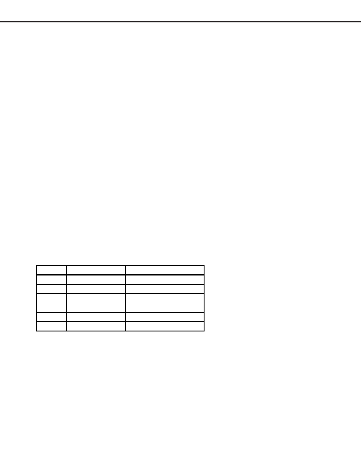
2-5. Speakers
No. ITEM SPECIFICATION
1 Nominal 8 ohms +/- 1.2%
2 Lowest Resonance 180 +/- 36Hz
Effective / Rated F0~20KHz
3
Frequency Range OUT PUT SPL-10dB
4 Rated Input 10W
5Maximum Input15W
Page 29
Page 30
MODELS: LT-3280D/LT-3780D
g
y
y
3.3.
Power circuit Power circuit
3.
Power circuit
3.3.
Power circuit Power circuit
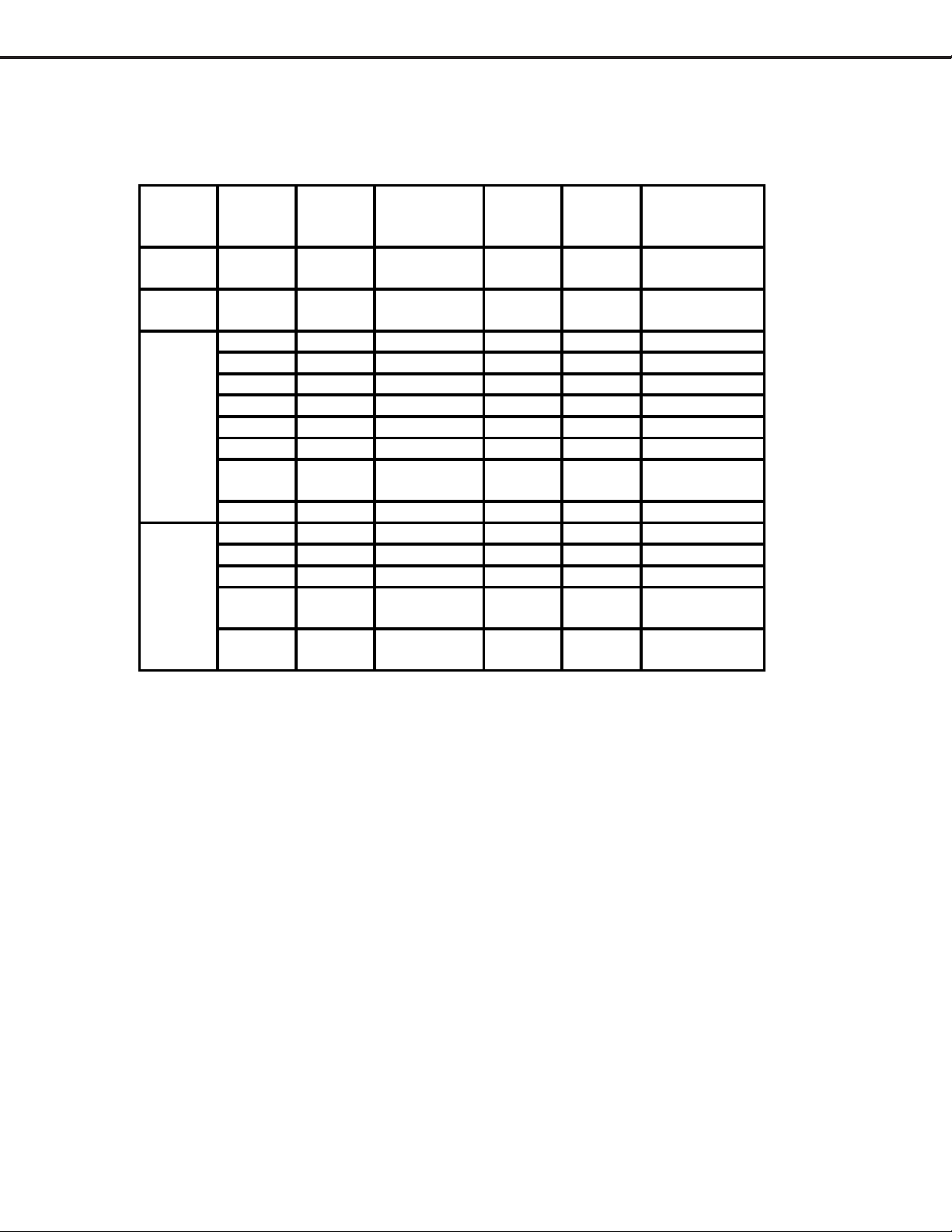
For power supply of LT-3280D and LT-3780D, there are the power supply of “always on” and “ON/OFF” with a
control signal.(Refer to BLOCK POWER.pdf)
PCB Power
source
si
POWER-
SUB1
POWER-
SUB2
POWER
120V 120V ON/OFF Psave1 For inverter.
24V 24 ON/OFF Psave1 For inverter.
24V 24 always on -For MAIN
18V 18 ON/OFF Psave4 IC9B5 Only 37”
P5V 5 ON/OFF Psave4 IC9B6 Only 32”
S8V 8 always on - IC9B4
S5V 5 always on - IC9B7
S3.3V 3.3 always on -IC830
AMPVC
4.5V 4.5 ON/OFF Psave2 IC9B2
MAIN
A3.3V 3.3 ON/OFF Psave2 IC9000
D3.3V 3.3 ON/OFF Psave2 IC9010
AD3.3V 3.3 ON/OFF Psave2 IC9020
D2.5V 2.5 ON/OFF Psave2.5 IC9030
A1.8V 1.8 ON/OFF Psave2.5 IC9040
nal
C
Voltage
[V ]
“always on”
or “ON/OFF”
Control
signal
17 ON/OFF Psave3 IC9B3
Output
IC
Onl
Note
37”
Onl
32”
(O)IC9A1, IC901(Only 32”) :
Power supply control IC(power factor correction) (FA5500/FA5501 : FUJI)
This IC are control IC for a power factor correction converter using critical conduction mode of
operation. This IC performs a power factor correction by conversion the current waveform from
triangle waveform to sine waveform. This IC and circuit is the same as LT-4260.
(P)IC9A2, IC902(Only 32”) : Power supply voltage control IC (F9222 : FUJI)
This IC controls the power supply voltage by switching about 75KHz.
This IC has MOSFET inside IC, keep switching on and off, and controls its duty to be stable output
voltage. . This IC and circuit is the same as LT-4260.
(Q)IC920(Only 37”) : Power supply voltage control IC (STR-G9628 : SANKEN)
This IC controls the power supply voltage by switching above 50kHz.
This IC has MOSFET inside IC, keep switching on and off, and controls its frequency to be stable output
voltage. And the duty is determined by input AC power voltage.
Page 30
Page 31
MODELS: LT-3280D/LT-3780D
A
)
A
A
4.4.
Protection CircuitProtection Circuit
4.
Protection Circuit
4.4.
Protection CircuitProtection Circuit
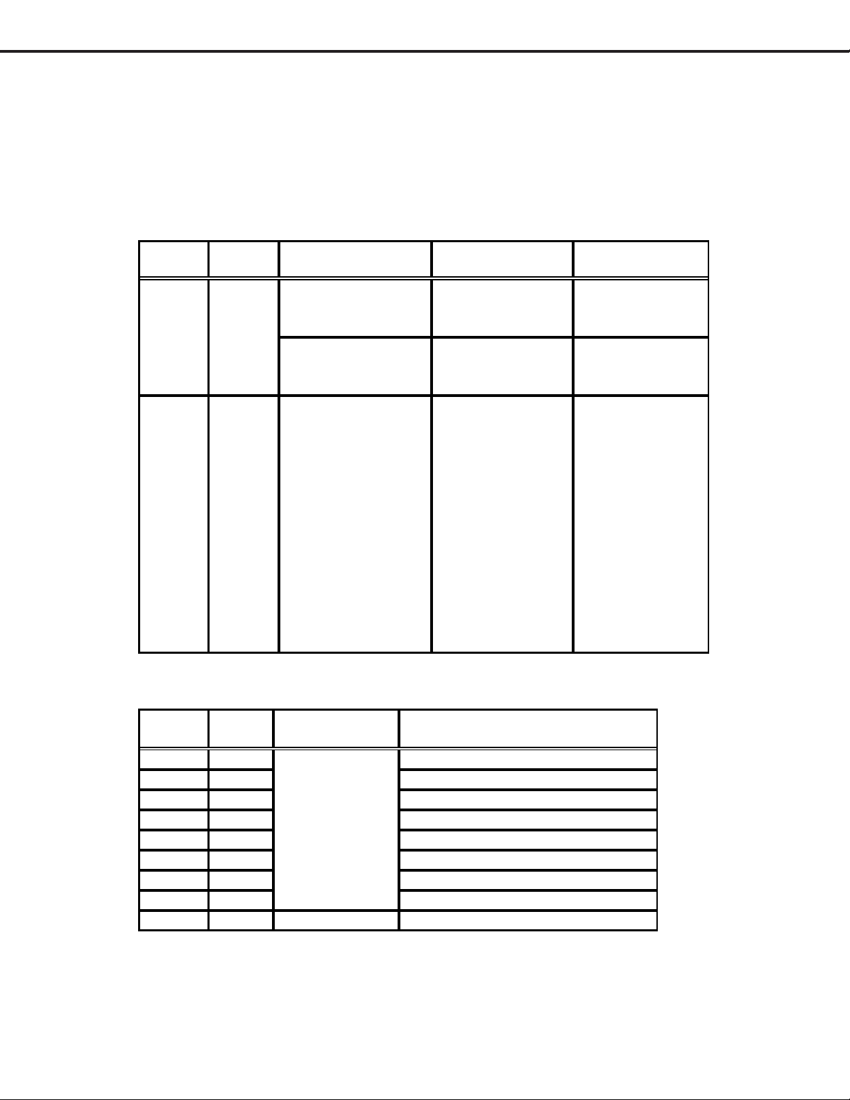
LT-3280D and LT-3780D has two protection circuits and some fuses.
If the protection circuits work, The LCD turns to stand-by mode.
The protection operation can be confirmed by the blinking of the blue power LED.
And the content can be confirmed by the number of blinking within one cycle.
The following table shows the content of the operation.
Protection Circuit:
Name
Number
of blinks
Short1 1
Short2 2
Fault Location
POWER-SUB1 or
Panel
POWER-SUB2 or
Panel
POWER or MAIN or
Panel (Only 18V or
P5V)
Cause
Excessive current
on the 120V line.
The 24V line on
the POWER-SUB2
is low.
The voltage on any
of the following
output lines is low.
18V
P5V
MPVCC(17V
4.5V
3.3V
D3.3V
D3.3V
D2.5V
A1.8V
Remark
Only LT-3780D
Only LT-3280D
Check the fuses
on POWER board.
(F9G2,F9G3,
F9G5~F9G8)
Fuses:
Part No. Rated
PCB Remark
Value
F9A1 6.3A AC line
POWER
F9G2 500mA S8V line ,S8V line for S5V
F9G3 1A 24V line for S8V and S5V.
F9G4 500mA 24V line for S3.3V and D1.8V.
F9G5 1.6A 24V line for AMP VCC.
F9G6 4A 24V line for 18V.
F9G7 1A 24V line for P5V.
F9G8 500mA 24V line for 4.5V.
F910 1A POWER-SUB1 IC920 is broken.
Page 31
Page 32

LT-3780/LT-3280 BLOCK-DIAGRAM
Page 32
PWB-MAIN
J7X0
RS232C
J500
J200
D-SUB
J304
IC201 IC202
IC200
C)
DIO
IC7X0
ADM3311
IC501
IC204
IC203
AD9888KSZ-170
(ADC)
X232C
IC500
iI9993CTG
IC700
HD64F2437FV
(MAIN_CPU)
IC503
C08
IC302
4334KS
X700
SHORT1 / AC_OFF
SHORT2
AVE1 / PSAVE2 /
RELAY(37inch only)
PSAVE2.5
IC703
X2J1
IC2C1
IC2A0
M66471FP
(Video process)
IC701
IC702
IC9020
IC400
gm1601
(Scaler & Video
Proceccor with CPU)
IC402
X400
MP7720DS
IC370
D3 3V)
IC400
(DDR-SDRAM)
25811
IC2A1
SiI1160CU
MDS T )
Writing
For
IC9040
18V)
IC401
2
IC9030
25V)
PSAVE4
BL_ON / BRIGHT
IC405
PM39LV040-
(PROM)
Writing
For
IC9050
18V)
A1.8V, D2.5V,
D3.3V,AD3.3V.
1
MC
IC9010
3V)
IC9000
33V)
To PANEL
VDS)
PANEL5V
32inch
PANEL18V
37inch
PD
PE
CNF1
CNF2
(37-
MB
18V,P5V,
AMPVCC,
S5V,
PD
PE
PWB-POWER
PSAVE1
PSAVE2
PSAVE3
PSAVE4
AY
AC_OFF
SHORT1
IC9B7
5V)
A
-IN
LCD-
L9A1
IC9B5
18V)
37i h O l )
IC9B6
5V)
32i h O l )
IC9B3
MP17
IC9B4
8V)
IC9B1
33V)
IC9B2
5V)
L9A2
NEL Control board
T9A1
V
IC9A2
2L
PFC-
RCUIT
D9A1
IDGE
K9A1
2
1
PWB-SERVICE PWB-CONTROL
2
PC PC
ERTER
SE
PWB-POWER-SUB
BL_ON / BRIGHT
T910(37inch)
/ T901(32inch)
IC9A2(37inch)
/ IC902(32inch)
D940(37inch)
/ D901(32inch)
AY
K910
37inch only
1
N2
MODELS: LT-3280D/LT-3780D
X301
IC301
MSP3440G
UDIO
IC380
MP7720DS
MA
B-
1
B-
2
B-
SPEAKER-R
SPEAKER-L
Page 33
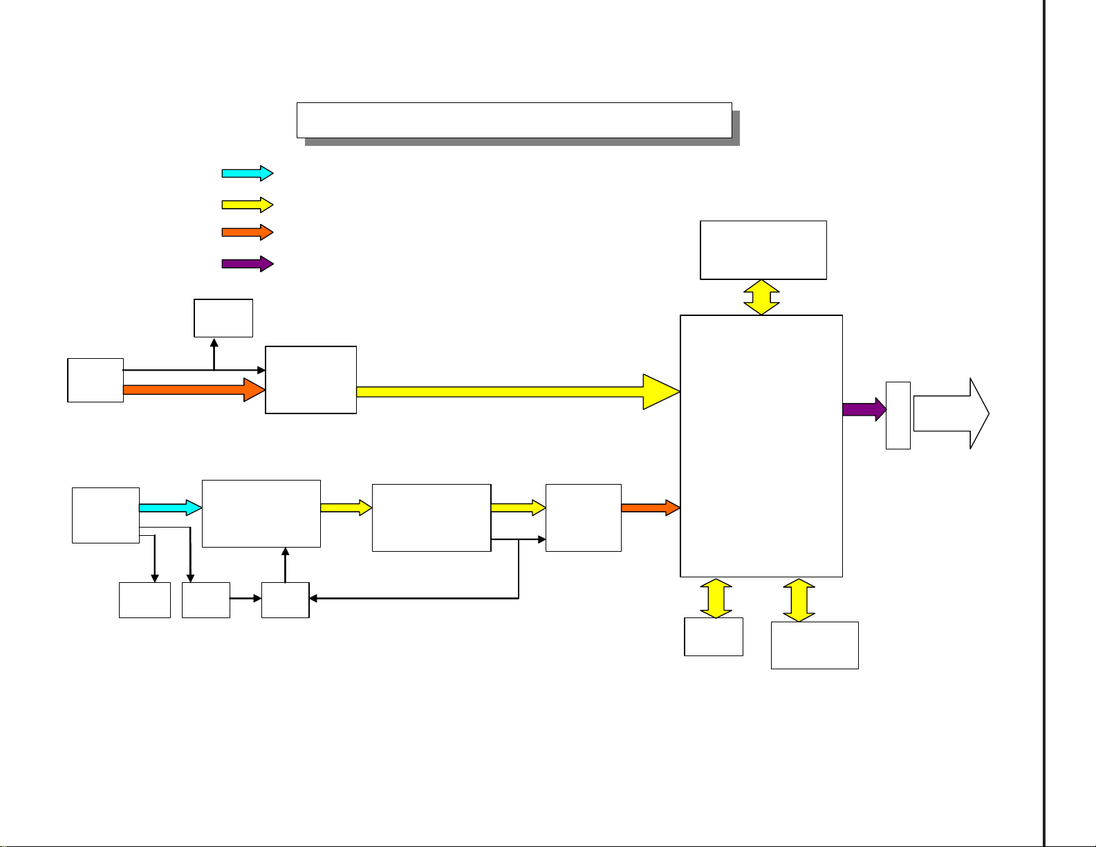
(
Analog signal
Digital signal
LT-3780/LT-3280 VIDEO BLOCK-DIA GRAM
Page 33
Differential signal
(TMDS)
Differential signal
(LVDS)
J500
HDMI
J200
D-SUB
(PC)
IC200
EEP1K
IC501
EEP2K
IC203
AD9888KSZ-170
(ADC for PC)
IC201
LCX14
IC500
SiI9993CTG
(HDMI_Rx)
IC202
LC08
IC2A0
M66471FP
(Video_process)
IC2A1
SiI1160CU
(TMDS_Tx)
IC403
(DDR-SDRAM)
IC400
Gm1601
(Scaler & Video processor
with CPU)
IC401
EEP32K
IC405
PM39LV040
4M PROM)
CNF1
MODELS: LT-3280D/LT-3780D
To PANEL
(LVDS)
Page 34

Page 34
PC AUDIO IN (J304)
MonitorLinkTM A/V
(J500)
5V_SCL
5V_SDA
L
R
HDMI receiver
(IC500)
SiI9993CTG
AUDIO CIRCUIT BLOCK-DIAGRAM for LT-3780/LT-3280
L
MUTE_MAIN
R
MUTE_MAIN
I2S
AUDIO DAC
(IC302)
CS4334-KSZ
|(
|(
|(
|(
AUDIO Processor
MSP3440G(IC301)
|(
|(
AMP
MP7720DS-Z
(IC380)
MODELS: LT-3280D/LT-3780D
AMP
MP7720DS-Z
(IC370)
|(
|(
MA
MUTE Circuit
(Q301~Q304)
L
SP
R
Page 35
Troubleshooting
1.1.
Power failurePower failure
1.
Power failure
1.1.
Power failurePower failure
(1)POWER is turned off.(1)POWER is turned off.
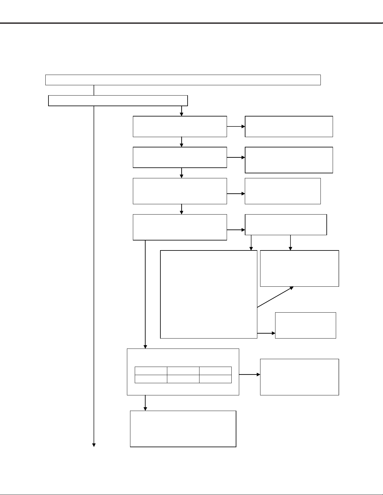
(1)POWER is turned off.
(1)POWER is turned off.(1)POWER is turned off.
Connect the Power plug and turn on the main Power switch (Front switch or remote switch).
Is the POWER LED lighting or blinking?
YES
MODELS: LT-3280D/LT-3780D
NO
Is the power plug conn ected to
the wall outlet correctly?
YES
Is all ha rn ess on board
connected correctly?
YES
NO
Connect the power plug
correctly.
NO
Connect all harness correctly.
Is the 24V output available at
the lead of L9B1?
NO
YES
Is the S3.3V output available at
NO
the cathode of D9G8?
YES
PD harness is removed after
F9G4 is repaired.
Connect the power plug again.
Is the S3. 3V output ava ilable at
the cathode of D9G8?
Is the AC-OFF output available at
10pin of PE?
Pin No. Voltage
PE 10 5V pulse
Pcba-POWER is out of
order.
Is F9G4 broken?
YES
IC9B1 or peripheral
circuit is out of order.
NO
YES
NO
PC9A4 or peripheral
circuit is out of order.
NO
Pcba-MAIN is out
of order.
Skip to
(A):In case of the POWER-LED blinking, (B): In case of the POWER-LED lighting.
YES
IC700 or peripheral circuit is out of
order. (Pcba-MAIN)
See other trouble guide.
Page 35
Page 36
MODELS: LT-3280D/LT-3780D
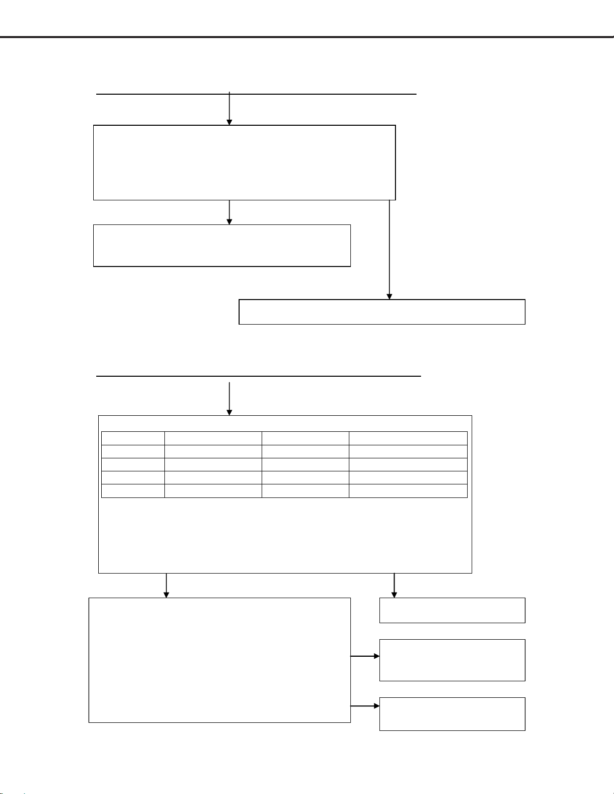
(A) In case of the POWER-LED blinking. (A) In case of the POWER-LED blinking.
(A) In case of the POWER-LED blinking.
(A) In case of the POWER-LED blinking. (A) In case of the POWER-LED blinking.
☆Short1 mode: The POWER-LE D blin kin g is 1 time within a cycle.
CN1 and CN2 harness are removed.
Connect the Power plug again and turn on the main Power switch
(Front switch or remote switch).
Is the POWER-LED still blinking?
YES
NO
Pcba-POWER-SUB1 is out of order.(Only LT-3780D)
Pcba-POWER-SUB2 is out of order.(Only LT-3280D)
The inverter circuit of LCD- panel is out of order.
☆Short2 mode: The POWER-LED blinking is 2 times within a cycle.
Confirm the following fuses. Repair the broken fuse.
Parts No. Rated value Output Measurement part
F9G5 1.6A AMPVCC(17V) Cathode of D9H5.
F9G6 1A P5V(only 32”) Cathode of D9J9.
F9G7 4A 18V(only 37”) Cathode of D9J2.
F9G8 0.5A 4.5V Cathode of D9H5.
PD and PE harness are removed after the broken fuse is repaired.
Connect the power plug again.
Is the voltage of 4.5V, AMPVCC(17V),P5V(only LT-3280D) and 18V(only LT3780D) output available?
YES
PD and PE harness are connected after the power plug is
removed.
CNF1(only32") or CNF2(only37") harness is removed.
Connect the power plug again and turn on the main
Power switch (Front switch or remote switch).
Is the voltage of 4.5V, AMPVCC(17V),P5V(only LT3280D) and 18V(only LT-3780D) output available?
Page 36
YES
NO
NO
Pcba-POWER is out of order.
The circuit of LCD-panel is
out of order.
Pcba-MAIN is out of order.
Page 37

MODELS: LT-3280D/LT-3780D
(B) In case of the POWER-LED lighting (B) In case of the POWER-LED lighting
(B) In case of the POWER-LED lighting
(B) In case of the POWER-LED lighting (B) In case of the POWER-LED lighting
Is the back-light on?
YES
Skip to “2. No picture
displayed and picture
errors.”
NO
Is the following harness connected?
CN1,CN2,CNF2
(only37”),PC,PE
YES
Confirms that the BLON voltage
of PE (Pin5).
Is the voltage of BLON more than
2V?
YES
Inverter circuit or back-light of LCD-
panel are out of order.
NO
Connec t th e h arness correctly.
NO
IC400 and peripheral circuits
are out of order. (PWB-MAIN)
Page 37
Page 38

MODELS: LT-3280D/LT-3780D
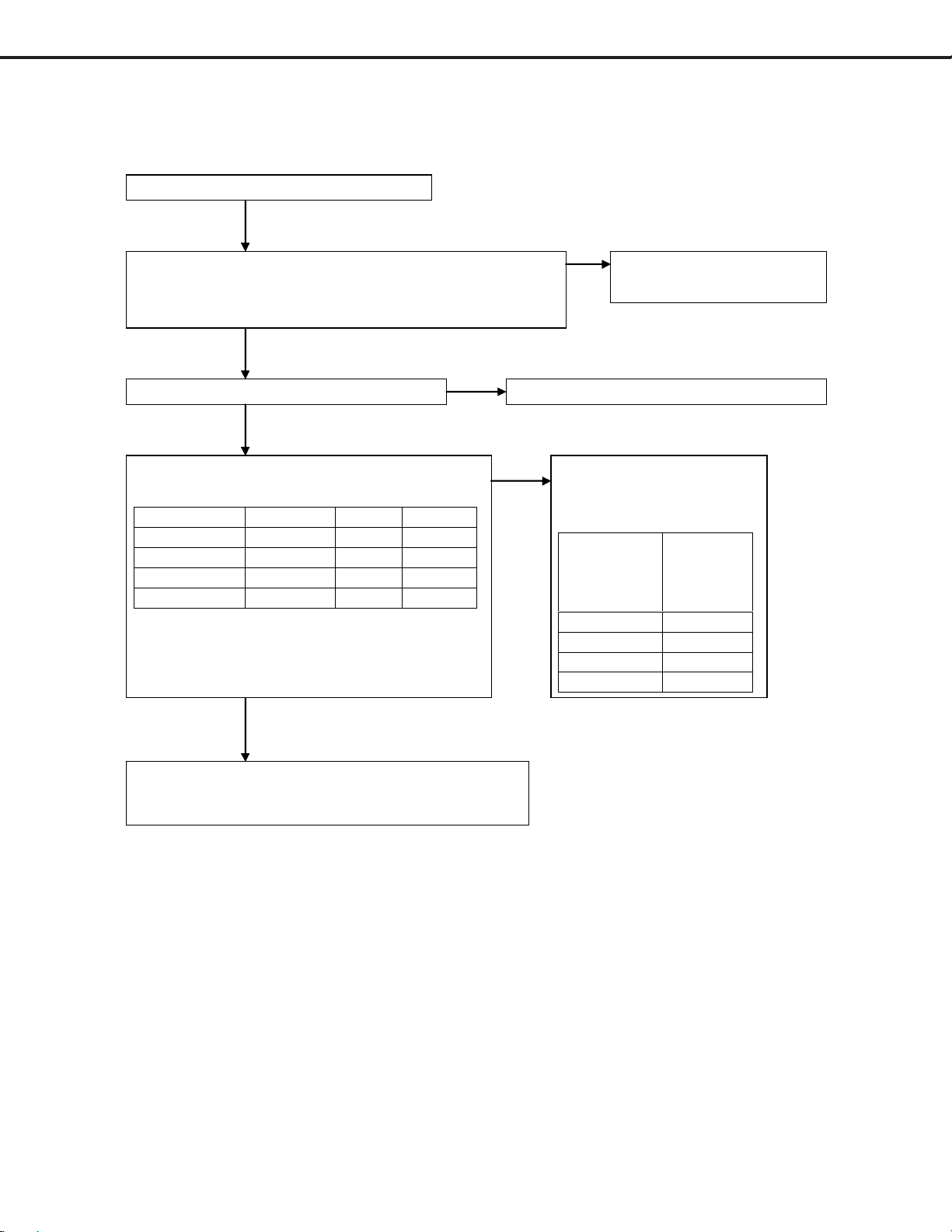
2. No picture displayed and picture errors.2. No picture displayed and picture errors.
2. No picture displayed and picture errors.
2. No picture displayed and picture errors.2. No picture displayed and picture errors.
Note ) It applies when there is no screen display or an unusual screen is outputted, although
24V(Voltage between pin4(GND) and pin6(24V) of Connecter-PC) from PWB-POWER
is outputted normally and the back light is turned on.
*Input source changes in following order with DEVICE UP button of remote control or DEVICE
button of front switch.
PC Monitor Link
2-1. No picture displayed and picture errors of all input.2-1. No picture displayed and picture errors of all input.
2-1. No picture displayed and picture errors of all input.
2-1. No picture displayed and picture errors of all input.2-1. No picture displayed and picture errors of all input.
Is all harness connected correctly?
(especially between PWB-MAIN
NO
Poor harness connection or
defective cabl e.
and LCD PANEL (CN F1))
YES
NO
Are the specified voltages available at the
connectors below?
CN
Name
Pin No. Vol tag
e
S5V PD 9 5Vdc
S3.3V PD 10,11 3.3Vdc
4.5V PD 12 4.5Vdc
Psave1* PE 2 3.3Vdc
Psave2* PE 3 3.3Vdc
Psave3* PE 4 3.3Vdc
* control signal of S3.3V
YES
Problem is in IC300 or IC400 or their
peripheral circ ui t s.
Please exchang e PWB-MAIN
Problem is in the followi ng
circuit (and peripheral
circuits) .
Volt age with
problem
PWB
including
the circuit
in problem
S5V
POWER
S3.3V POWER
4.5V
Psave1
POWER
MAIN
Psave2 MAIN
*When it cannot still fix, it may have a problem with LCD-Module.*When it cannot still fix, it may have a problem with LCD-Module.
*When it cannot still fix, it may have a problem with LCD-Module.
*When it cannot still fix, it may have a problem with LCD-Module.*When it cannot still fix, it may have a problem with LCD-Module.
Page 38
Page 39

MODELS: LT-3280D/LT-3780D
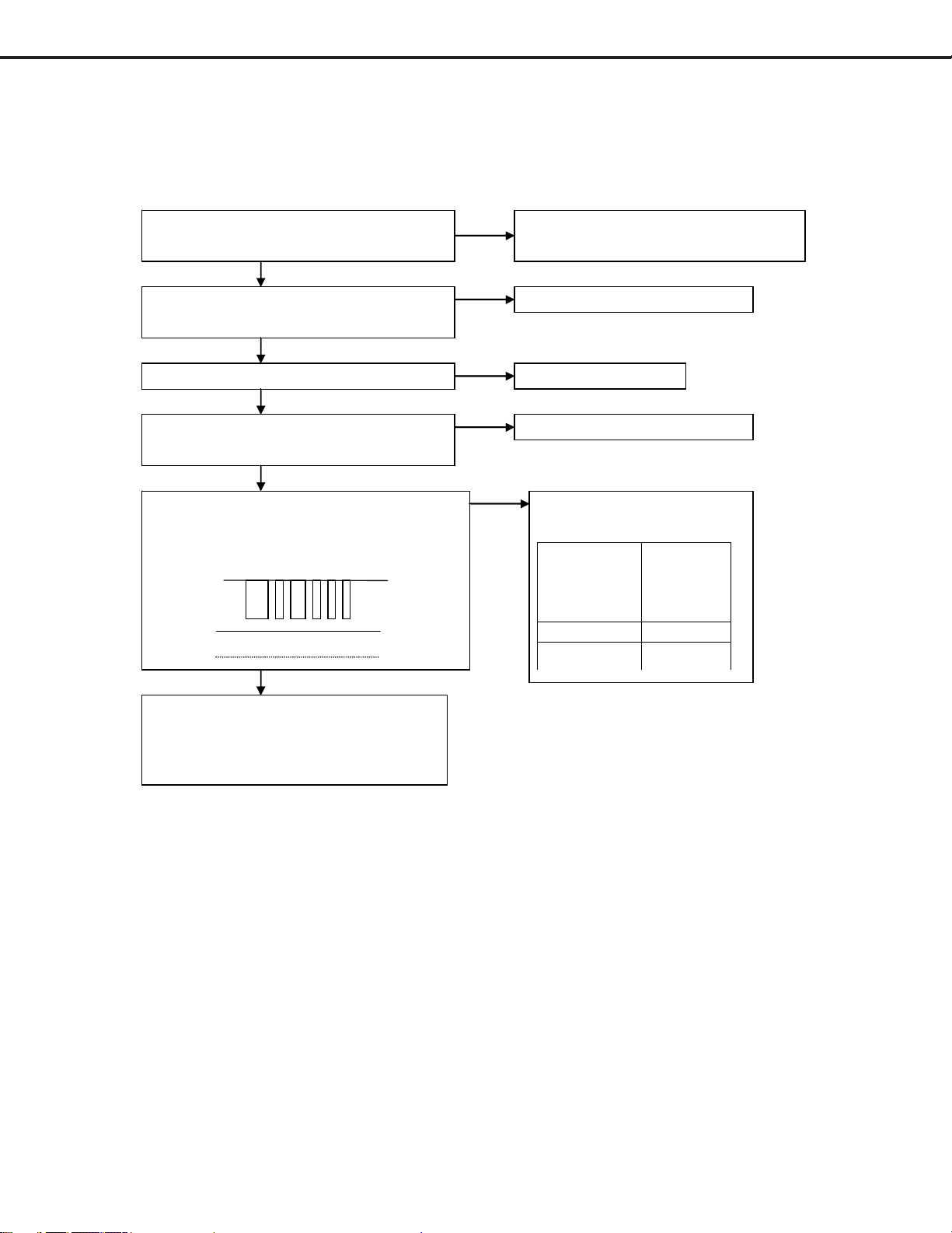
2-2. No picture displayed and picture errors of PC signal only2-2. No picture displayed and picture errors of PC signal only
2-2. No picture displayed and picture errors of PC signal only
2-2. No picture displayed and picture errors of PC signal only2-2. No picture displayed and picture errors of PC signal only
Enter an input of WXGA(1360x768:6 0Hz ) or XGA
(1024x768:60Hz) gray scale in D-sub connector(J200),
and select PC INPUT.
The video level inputs above 0.7Vp-p.
NO
Is all harness connected correctly?
Poor harness connection or
defective cable .
YES
Problem is in IC203 or IC2A0 or IC2A1 or
IC200 or their peripheral ci r cui ts.
Please exchang e PWB-MAIN
..
.
..
0.7Vp-p
2-3. No picture displayed and picture errors of HDMI signal only2-3. No picture displayed and picture errors of HDMI signal only
2-3. No picture displayed and picture errors of HDMI signal only
2-3. No picture displayed and picture errors of HDMI signal only2-3. No picture displayed and picture errors of HDMI signal only
Enter gray scale pattern of 1080i timing
in J500 connect or , and sele ct HDMI INPUT.
And then, perform AV reset by front switch.
The video level inputs above 0.7Vp-p.
NO
Is all harness connected correctly?
Poor harness connection or
defective cable .
YES
Problem is in IC500 or IC501 or their
Peripheral circuits.
Please exchang e PWB-MAIN
..
.
..
Page 39
Page 40
MODELS: LT-3280D/LT-3780D
3. No audio output generated.3. No audio output generated.
3. No audio output generated.
3. No audio output generated.3. No audio output generated.
3-1. No all audio output generated.3-1. No all audio output generated.
3-1. No all audio output generated.
3-1. No all audio output generated.3-1. No all audio output generated.
Enter audio input signa l. ( ex. PC Audio )
Is all harness connect ed co rrect ly?
(Especially between PWB-MAIN and PWB-CONNECT(MA)
and PWB-CONNECT and SPEAKER(SP))
YES
NO
Raise volume level. And MUTE is turne d of f . Volume level is not 0. And MUTE is of f.
YES
Are the specified voltages available at the
NO
pins below? (Power source check)
CN Name Pin No. Voltage
S5V PD 9 5Vdc
S8V PD 8 8Vdc
AMPVCC PD 7 17Vdc
Psave3* PE 4 3Vdc
*control signal of AMPVC C
NO
Poor harness connection or
defective cable.
Problem is in the following
circuit (and peripheral
circuits) .
Voltage with
problem
PWB
including
the circuit
in problem
S5V
S8V
AMPVCC
Psave3
POWER
POWER
POWER
MAIN
YES
Problem is in IC301 or their peripheral circuits.
Please exchang e PWB-MAIN
*When it cannot still fix, it may have a problem with SPEAKER.*When it cannot still fix, it may have a problem with SPEAKER.
*When it cannot still fix, it may have a problem with SPEAKER.
*When it cannot still fix, it may have a problem with SPEAKER.*When it cannot still fix, it may have a problem with SPEAKER.
Page 40
Page 41

MODELS: LT-3280D/LT-3780D
3-2. 3-2.
No each(L or R) of audio output generated.No each(L or R) of audio output generated.
3-2.
No each(L or R) of audio output generated.
No each(L or R) of audio output generated.No each(L or R) of audio output generated.
3-2. 3-2.
Enter audio input signa l. ( ex. PC Audio )
Is all harness connect ed co rrect ly?
(Especially between PWB-MAIN and PWB-CONNECT(MA),
PWB-CONNECT and SPEAKER(SP))
NO Poor harness connection or
defective cable.
YES
NO
It adjusts BALANCE to cen t er. BALANCE level is center.
YES
Problem is in IC370 or IC380 or their
peripheral circuits.
Please exchang e PWB-MAIN
3-3. 3-3.
No HDMI audio output generated.No HDMI audio output generated.
3-3.
No HDMI audio output generated.
No HDMI audio output generated.No HDMI audio output generated.
3-3. 3-3.
In case of no HDMI audio output generates, problem is in IC500 or IC302 or their peripheral Circuits.
Please exchange
PWB-MAIN.PWB-MAIN.
PWB-MAIN.
PWB-MAIN.PWB-MAIN.
3-4. 3-4.
No PC audio output generated.No PC audio output generated.
3-4.
No PC audio output generated.
No PC audio output generated.No PC audio output generated.
3-4. 3-4.
In case of no PC
Please exchange
3-5. When you turn up volume(over 50), there is noise from speaker3-5. When you turn up volume(over 50), there is noise from speaker
3-5. When you turn up volume(over 50), there is noise from speaker
3-5. When you turn up volume(over 50), there is noise from speaker3-5. When you turn up volume(over 50), there is noise from speaker
Please exchange the parts of
C37A and C38A : from 220ƒÊF to 470ƒÊF
C371 and C381 : from 0.47ƒÊF to 0.1ƒÊF
If PWB-CONNECT number is “211A77601”, please exchange this PWB-CONNECT to the PWB-CONNECT
that number is “ 211A84201”.
audio output generates, problem is in J304 or their peripheral circuits.
PWB-MAIN.PWB-MAIN.
PWB-MAIN.
PWB-MAIN.PWB-MAIN.
..
.
..
PWB-MAIN PWB-MAIN
PWB-MAIN as below
PWB-MAIN PWB-MAIN
..
.
..
Page 41
Page 42
MODELS: LT-3280D/LT-3780D
4. Other faults4. Other faults
4. Other faults
4. Other faults4. Other faults
Notes) It considers the case where there are problems except 1, 2, 3.
4-1. Remote control is not effective.4-1. Remote control is not effective.
4-1. Remote control is not effective.
4-1. Remote control is not effective.4-1. Remote control is not effective.
After checking the polarity of batteries, has
it loaded correctly?
NO
Load the batteries , making sure the
polarities (-) and (+) are correct .
YES
Regarding as the slide switch at the top of
the remote, does it set as “TV”?
YES
Does it use within 20 feet ?
YES
It does not operate, even if it exchanges for
new batteries.
YES
When it pushes the remote switch, is the
signal below available at pin 8,6, of MB
(remote switc h use) ?
8:
3Vp-p
5Vdc 6
YES
Problem is in IC700 or their peripheral
circuits.
Please exchange PWB-MAIN
NO
NO
NO
NO
It sets the slide switch as “ TV”.
it uses within 20 feet.
It exchanges on new batteries.
Problem is in the following
PWB (and peripheral circ uits).
Pin wit h
problem
PWB
including
the circuit
in problem
8 of MB
6 of MB
LED
MAIN or
Page 42
Page 43

MODELS: LT-3280D/LT-3780D
4-2. Button switch is not effective.4-2. Button switch is not effective.
4-2. Button switch is not effective.
4-2. Button switch is not effective.4-2. Button switch is not effective.
Is the following harness connected correctly?
・ Between PWB-MAIN and PWB-
NO
Poor harness connection or
defective cable.
CONTROL
YES
NO
When it pushes the button switch, is the
signa l
Part on PWB-CONTROL is out
of order.
below available at pins 2, 3, of MC ?
3Vp-p only when switch is not pushed.
2, 3 :
Not 3V only when switch is pushed.
(It depends on switch)
YES
IC700 (and peripheral circuits) are out of order.(PWB-MAIN)
Page 43
Page 44

MODELS: LT-3280D/LT-3780D
LT-3280 Parts List
Part Number Description
260-320006-011 BAR-BEZEL FRONT
200-320039-0101 BEZEL-FRONT
250-320026-011 BRACKET-PANEL
250-320025-011 BRACKET-POWER
250-000034-011 BRACKET-STAND BASE
250-000033-011 BRACKET-STAND FRAME
250-320003-011 BRACKET-WALL MOUNT
200-370016-0101 BUTTON-POWER
240-000008-011 CABLE-FLAT CLIP
170-021803-101 CORD-POWER
200-320044-0101 COVER-AV1
200-320045-0101 COVER-AV2
200-320043-0101 COVER-BACK
200-320046-0101 COVER-DTV
250-370006-011 HINGE-ASSY
I/B LT3280 I/B LT3280/LT3780
180-320001-101 LCD (MODULE 1920*1080) 32" (T/A REQ)
PSM-2048 MOUNT-WALL
200-320042-0101 PANEL-FUNCTION KEY
200-320040-0101 PANEL-LEFT
200-320041-0101 PANEL-RIGHT
210-320004-011 PLATE-PC
510-322010-021 PWB-CONNECT (LT-3280/LT-3780)
510-322011-011 PWB-CONTROL (LT- 3280/LT- 3780)
510-322008-011 PWB-IR (LT-3280/LT-3780)
510-322009-011 PWB-LED (LT-3280/LT-3780)
510-322007-011 PWB-MAIN (LT-3280) (T/A REQ)
185-015001-101 PWB-P SUB2 (AC/DC 150 W)(LT3280) T/A REQ
185-023002-101 PWB-POWER SUPPLY(230W)(LT3280) T /A REQ
510-322012-011 PWB-SERVICE BOARD (LT-3280/LT-3780)
I/QR LT3280 QUICK REFERENCE LT3280/LT3780
290P118020 REMOTE
154-080801-101 SPEAKER 10W 8R (2 EA)
200-370021-0101 STAND-BASE PLASTIC
220-000004-011 STAND-BASE RUBBER (6 pcs/PKG)
200-370018-0101 STAND-FRAME COVER
200-370019-0101 STAND-FRAME PLASTIC COVER
200-370020-0101 STAND-FRONT PLATE
250-000036-011 STAND-STAY
220-320001-011 STAND-SUPPORT RUBBER
Page 44
Page 45

MODELS: LT-3280D/LT-3780D
LT-3780 Parts List
Part Number Description
260-370002-011 BAR-BEZEL FRONT
200-370009-0101 BEZEL-FRONT
250-370001-011 BRACKET-PANEL SUPPORT RL (37")
250-370002-011 BRACKET-PANEL SUPPORT TB (37")
250-000034-011 BRACKET-STAND BASE
250-000033-011 BRACKET-STAND FRAME
250-370004-011 BRACKET-WALL MOUNT
200-370016-0101 BUTTON-POWER
170-021803-101 CORD-POWER
200-370022-0101 COVER-AV1
250-370006-011 HINGE-ASSY
I/B LT3780 I/B LT3280/LT3780
543-370001-001 KIT-COVER BACK LT-3780
180-370001-201 LCD (MODULE 1920*1080) 37" (T/A REQ)
PSM-2048 MOUNT-WALL
200-370015-0101 PANEL-FUNCTION KEY
200-370010-0101 PANEL-SIDE LEFT
200-370011-0101 PANEL-SIDE RIGHT
210-370002-011 PLATE-PC
510-322010-021 PWB-CONNECT (LT-3280/LT-3780)
510-322011-011 PWB-CONTROL (LT-3280/LT-3780)
510-322008-011 PWB-IR (LT-3280/LT -3780)
510-322009-011 PWB-LED (LT-3280/LT- 3780)
510-372001-011 PWB-MAIN (LT-3780) (T/ A REQ)
185-021001-101 PWB-P SUB1 (210W) (LT3780) T/A REQ
185-023003-101 PWB-POWER-SUPPLY(230W)(LT3780) T/A REQ
510-322012-011 PWB-SERVICE BOARD (LT-3280/LT-3780)
I/QR LT3780 QUICK REFERENCE LT3280/LT3780
154-080801-101 SPEAKER 10W 8R (2 EA)
200-370021-0101 STAND-BASE PLASTIC
220-000004-011 STAND-BASE RUBBER (6 pcs/PKG)
200-370018-0101 STAND-FRAME COVER
200-370019-0101 STAND-FRAME PLASTIC COVER
200-370020-0101 STAND-FRONT PLATE
250-000036-011 STAND-STAY
Page 45
Page 46

MODELS: LT-3280D/LT-3780D
Page 46
Page 47
21 3 4 5 6 7 8 9 10 11 12 13 14 15 16
32inch(LT-3280D) 37inch(LT-3780D)
a
SERVICE
RESERVED
SP_L_P
SP_L_N
SP_R_P
SP_R_N
SM10B-SRSS-TB(LF)(SN)S7B-PH-SM3-TB(LF)(SN)B4B-XH-AM(LF)(SN)S5B-PH-K-S(LF)(SN)
1
RXD1
2
TXD1
3
SCK1
4
FWE
5
MD2
6
MD1
MS1
7
MD0
8
RES
9
GND
10
VCC
AWG26
1
S3.3V
2
SDA
3
SCL
4
GND
MS2
5
GEN_W
6
S5V
7
AWG26
1
2
MA
3
4
へ
37’
37’
37’
37’
37’
37’
37’
37’
37’
37’
AWG24
用より未使用
用より未使用
用より未使用
用より未使用
用より未使用
用より未使用
用より未使用
用より未使用
用より未使用
用より未使用
JBS-25S-3A3F90(LF)(SN)
1
へ
SPEAKER
RXD1
2
SCK1
3
MD2
4
MD0
5
GND
6
7
8
9
10
S3.3V
11
SCL
12
GEN_W
13
RESERVED
SE
14
TXD1
15
FWE
16
MD1
17
RES
18
VCC
19
20
21
22
23
SDA
24
GND
25
S5V
CONNECT
B4B-PH-K-S(LF)(SN)
1
SP_L_P
2
SP_L_N
SP
3
SP_R_P
4
SP_R_N
b
c
d
e
f
LCD Panel
g
CONTROL
1
RESERVED
PWR_SW
GND
2
KEY1
3
KEY0
MC
4
5
h
MAIN
1
RXD1
2
TXD1
3
SCK1
4
FWE
5
MD2
6
MD1
MS1
7
MD0
8
RES
9
GND
10
VCC
B7B-PH-K-S(LN)(SN) BM10B-SRSS-TB(LF)(SN)B4B-XH-AM(LF)(SN)
1
S3.3V
2
SDA
3
SCL
4
GND
MS2
5
GEN_W
6
S5V
7
RESERVED
1
SP_L_P
2
SP_L_N
MA
3
SP_R_P
4
SP_R_N
FI-W41P-HFE
1
GND
2
RPF
3
SELLVDS
4
NC
5
NC
6
ODSEL1
7
ODSEL2
8
GND
9
ERX0-
10
ERX0+
11
ERX1-
12
ERX1+
13
ERX2-
14
ERX2+
15
ECLK-
16
ECLK+
17
ERX3-
18
ERX3+
19
GND
20
ORX0-
21
ORX0+
CNF1
22
ORX1-
23
ORX1+
24
ORX2-
25
ORX2+
26
OCLK-
27
OCLK+
28
ORX3-
29
ORX3+
30
GND
31
GND
32
GND
33
GND
34
GND
35
GND
36
GND
37
POWER;+5V
38
POWER;+5V
39
POWER;+5V
40
POWER;+5V
41
POWER;+5V
B5B-PH-K-S(LF)(SN)
1
GND
2
KEY1
3
KEY0
MC
4
PWR_SW
5
RESERVED
AMPVCC
PSAVE1
PSAVE2
PSAVE3
BRIGHT
PSAVE4
SHORT1
AC-OFF
STB_RMC
LCD_RMC
RESOUT
S3.3V
S3.3V
4.5V
BLON
BLUE
AMBER
ETCK
ETRST
ETDO
ETMS
ETDI
NC
NC
GND
GND
P5V
GND
S8V
S5V
10
11
12
13
GND
14
GND
GND
GND
10
S5V
GND
S5V
GND
GND
1
2
3
4
5
6
7
RES
8
GND
9
GND
10
GND
11
VCC
12
GND
13
GND
14
GND
1
2
3
4
5
6
7
PD
8
9
B10B-PH-K-S(LF)(SN)
1
2
3
4
5
PE
6
7
8
9
B9B-PH-K-S(LN)(SN) B13(14)B-XH-K(LF)(SN)
1
2
3
4
5
MB
6
7
8
9
HUDI
MD
D-sub9
(PC)
(DV11201-P33-4F)
J200J304J500J7X0
PC AUDIO in
(LGY6502-0800F)
HDMI1
(DC1R019JDA)
RS232C
(DT10121-R3T-4F)
POWER
B13(14)B-XH-K(LF)(SN)
1
NC
2
NC
3
GND
4
GND
5
P5V
6
GND
7
AMPVCC
PD
8
S8V
9
S5V
10
S3.3V
11
S3.3V
12
4.5V
13
GND
14
AWG24
AWG26
GND
B10B-PH-K-S(LF)(SN)
1
GND
2
PSAVE1
3
PSAVE2
4
PSAVE3
5
BLON
PE
6
BRIGHT
7
PSAVE4
8
GND
9
SHORT1
10
AC-OFF
BRIGHT
BLON
SHORT
NC
GND
24V
NC
B6(7)B-XH-K(LF)(SN)
1
2
3
4
PC
5
6
7
AWG26
P-SUB2
B6(7)B-XH-K(LF)(SN)
1
BLON
2
NC
3
BRIGHT
4
GND
PC
5
SHORT
6
24V
7
NC
IR
1
S5V
2
STB_RMC
MB2
3
GND
AC IN
AWG18
B2P(4-2,3)-VH-BK(LF)
1
L
2
N.C L
PA
3
N.C
4
N
1
L
2
N.C
PB
3
N
AWG18
B2P3-VH-BK(LF)
1
2
N.C
PB
3
N
LED
INVERTER
S6B-PH-K-S(LF)(SN) S3B-PH-K-S(LF)(SN)
1
BLUE
2
AMBER
3
S5V
4
GND
MB1
5
LCD_RMC
6
GND
AWG26
TO
デバッガー
VBL(+24V)
VBL(+24V)
VBL(+24V)
VBL(+24V)
VBL(+24V)
VBL(+24V)
VBL(+24V)
VBL(+24V)
VBL(+24V)
S10B-PH-SM3 B2P3-VH-BK(LF)
1
2
3
4
5
6
GND
CN1
7
GND
8
GND
9
GND
10
GND
1
2
3
4
5
NC
6
GND
7
GND
8
GND
9
SEL
10
E_PWM
11
I_PWM
12
BLON
AWG24
S12B-PH-SM3
CN2
AWG24
B10B-PH-K-S(LF)(SN)
1
VBL(+24V)
2
VBL(+24V)
3
VBL(+24V)
4
VBL(+24V)
5
VBL(+24V)
6
GND
CN1
7
GND
8
GND
9
GND
10
GND
B12B-PH-K-S(LF)(SN)
1
VBL(+24V)
2
VBL(+24V)
3
VBL(+24V)
4
VBL(+24V)
5
NC
6
GND
7
GND
CN2
8
GND
9
GND
GND
10
BRIGHT
11
12
BLON
AWG26
JBS-25S-3A3F90(LF)(SN)
SE
B4B-PH-K-S(LF)(SN)
へ
SP
SPEAKER
SERVICE
1
RXD1
2
SCK1
3
MD2
4
MD0
5
GND
6
7
8
9
10
S3.3V
11
SCL
12
GEN_W
13
RESERVED
14
TXD1
15
FWE
16
MD1
17
RES
18
VCC
19
20
21
22
23
SDA
24
GND
25
S5V
CONNECT
1
SP_L_P
2
SP_L_N
3
SP_R_P
4
SP_R_N
LCD Panel
CONTROL
RESERVED
SP_L_P
SP_L_N
SP_R_P
SP_R_N
PWR_SW
RESERVED
RXD1
TXD1
SCK1
MD2
MD1
MD0
RES
GND
VCC
S3.3V
SDA
SCL
GND
GEN_W
S5V
GND
KEY1
KEY0
SM10B-SRSS-TB(LF)(SN)
1
2
3
4
5
6
MS1
7
8
9
10
S7B-PH-SM3-TB(LF)(SN)
1
2
3
4
MS2
5
6
7
B4B-XH-AM(LF)(SN)
1
2
MA
3
4
LCD Panel
へ
B5B-PH-K-S(LF)(SN)
1
2
3
MC
4
5
a
MAIN
BM10B-SRSS-TB(LF)(SN)
1
RXD1
2
TXD1
3
SCK1
4
FWEFWE
5
MD2
6
MD1
MS1
7
MD0
8
RES
9
GND
10
VCC
AWG26
AMPVCC
S3.3V
S3.3V
18V
NC
GND
GND
NC
GND
S8V
S5V
4.5V
GND
GND
B13(14)B-XH-K(LF)(SN)
1
2
3
4
5
6
7
PD
8
9
10
11
12
13
14
AWG24
POWER
B13(14)B-XH-K(LF)(SN)
1
18V
2
NC
3
GND
4
GND
5
NC
6
GND
7
AMPVCC
PD
8
S8V
9
S5V
10
S3.3V
11
S3.3V
12
4.5V
13
GND
14
GND
BRIGHT
SHORT1
BLON
RELAY
NC
GND
24V
IG
SYN
GND
18V
B10(11)B-XH-K(LF)(SN)
1
2
3
4
5
6
PC
7
8
9
10
11
P-SUB1
B10(11)B-XH-K(LF)(SN)
1
BLON
2
NC
3
BRIGHT
4
GND
5
SHORT1
6
24V
PC
7
RELAY
8
IG
9
SYN
10
GND
11
AWG26
18V
b
c
B7B-PH-K-S(LF)(SN)
1
S3.3V
2
SDA
3
SCL
4
GND
MS2
5
GEN_W
6
S5V
7
RESERVED
AWG26
B4B-XH-AM(LF)(SN)
1
SP_L_P
2
SP_L_N
MA
3
SP_R_P
4
53261-0690
1
2
3
4
CNF2
5
6
SP_R_N
VCC(+18V)
VCC(+18V)
VCC(+18V)
GND
GND
GND
AWG24
へ
PSAVE1
PSAVE2
PSAVE3
BRIGHT
PSAVE4
SHORT1
AC-OFF
B13B-PH-K-S(LN)(SN)
1
GND
2
3
4
5
BLON
6
7
PE
8
GND
9
10
11
RELAY
12
IG
13
SYN
AWG26
IR
S3B-PH-K-S(LF)(SN)
1
S5V
2
STB_RMC
MB2
3
GND
AC IN
AWG18
B13B-PH-K-S(LF)(SN)
1
GND
2
PSAVE1
3
PSAVE2
4
PSAVE3
5
BLON
6
BRIGHT
7
PSAVE4
PE
8
GND
9
SHORT1
10
AC-OFF
11
RELAY
12
IG
13
SYN
B2P(4-2,3)-VH-BK(LF)
1
L
2
N.C
PA
3
N.C
4
N
d
B2P3-VH-BK(LF)
1
L
2
N.C
PB
3
N
AWG18
B2P3-VH-BK(LF)
1
L
2
N.C
PB
3
N
e
LED
INVERTER
VBL(+120V)
VBL(+120V)
VBL(+120V)
f
S10B-PH-SM3
1
GND
2
GND
3
GND
4
NC
5
IG
6
SYN
CN2
7
SEL
8
E_PWM
9
I_PWM
10
BLON
1
2
3
4
NC
5
NC
6
GND
7
GND
8
GND
9
GND
10
GND
11
18V
12
18V
AWG24
S12B-PH-SM3
CN1
AWG24
B10B-PH-K-S(LF)(SN)
1
GND
2
GND
3
GND
4
NC
5
IG
6
SYN
CN2
7
GND
8
GND
9
BRIGHT
10
BLON
B12B-PH-K-S(LF)(SN)
1
VBL(+120V)
2
VBL(+120V)
3
VBL(+120V)
4
NC
5
NC
6
GND
7
GND
CN1
8
GND
9
GND
10
GND
11
18V
12
18V
g
h
32’
32’
32’
32’
32’
32’
32’
32’
32’
32’
32’
AWG26
用より未使用
用より未使用
用より未使用
用より未使用
用より未使用
用より未使用
用より未使用
用より未使用
用より未使用
用より未使用
用より未使用
FI-W41P-HFE
1
GND
2
RPF
3
NC
4
NC
5
NC
6
ODSEL1
7
ODSEL2
8
GND
9
ERX0-
10
ERX0+
11
ERX1-
12
ERX1+
13
ERX2-
14
ERX2+ AWG26
15
ECLK-
16
ECLK+
17
ERX3-
18
ERX3+
19
GND
20
ORX0-
21
ORX0+
CNF1
22
ORX1-
23
ORX1+
24
ORX2-
25
ORX2+
26
OCLK-
27
OCLK+
28
ORX3-
29
ORX3+
30
GND
31
GND
32
GND
33
GND
34
GND
35
GND
36
GND
37
POWER;+5V
38
POWER;+5V
39
POWER;+5V
40
POWER;+5V
41
POWER;+5V
B5B-PH-K-S(LF)(SN)
1
GND
2
KEY1
3
KEY0
MC
4
PWR_SW
5
RESERVED
STB_RMC
LCD_RMC
RESOUT
B9B-PH-K-S(LN)(SN)
1
S5V
2
3
GND
4
BLUE
5
AMBER
MB
6
S5V
7
GND
8
9
GND
HUDI
1
ETCK
2
ETRST
3
ETDO
4
5
ETMS
6
ETDI
7
RES
MD
8
GND
9
GND
10
GND
11
VCC
12
GND
13
GND
14
GND
D-sub9
(PC)
(DV11201-P33-4F)
J200
PC AUDIO in
(LGY6502-0800F)
J304
HDMI1
(DC1R019JDA)
J500
RS232C
(DT10121-R3T-4F)
J7X0
TO
デバッガー
S6B-PH-K-S(LF)(SN)
1
BLUE
2
AMBER
3
S5V
4
GND
MB1
5
LCD_RMC
6
GND
i
j
i
j
LT-3780D2
LT-3280D
1
CHANGE
改定
32 33 34 35
標
改番
マ
副番 品番
CHANGE
|
SUB
ク
ITEM
MARK
ITEM
規格
*
出図先 尺度
3RD ANGLE
第3角法
PROJECTION
作成 照査
DRAWN CHECKED
CAD
MATERIAL
SCALE
DIM
IN
mm
設計 検認
DESIGNED
中井
NTS
AND DIMENSIONS
作成日付
2005 7 11
APPROVED
DATE
21 3 4 5 6 7 8 9 10 11 12 13 14 15 16
69 70 71 7972 73 74 75 76 77 78 80
C
O
(MI)
UNIT
C
O
MARK
CODE
M
APP. FROM
5
図
名
SCHEMATIC-DIAGRAM
REVISION NO.
TITLE OF DRAWING
25 26 27 28 29 30 31
880A647
改
摘
理同期
REMARK
**
(1/14)
SCL=1/1.4
要
24
Page 48

2345678910111
GM1601PC
GM1601
5VSCL 5VSDA A3.3SCL A3.3SDA
S5V
a
b
R7G8
4.7K
7WC8
VCC
IC703
24LC64TI/SNG
1EO2E13E24
4.7K
R7G7
5
SDA6SCL
VSS
DG
4.7K
R7G6
DDC_SCL
DDC_SDA
AMPVcc
10K10K
10K
R7T2
c
d
SHORT2
R7T1
Q7T1
A1235A
100uF25V
C7T1
R7T4
1K
R7T3
SYN
IG
RELAY
PSAVE4
e
PSAVE2_5
R7G5
Q7T2
C3052
5V_SDA
5V_SCL
R7G3
4.7K
Q700
4.7K
NDC7002N
D2
5
S1
6
D1
3G24
R7J7
0
2S2
R7G4
4.7K
1G1
R7J8
0
A3.3V_SCL
4.7K
R7J6
4.7K
R7J5
NDC7002N
4.7K
4.7K
R7H1
R7H2
R7S1
470
1/16W
R7H3
100
R7H4
100
R7H5
100
R7H6
100
R7P1
10K
R7P3
10K
10K
R7P4
SHORT2
C7S3R7S2
10u3.3K
1/16W
32"
R7T8
10K
1/16W
4.7K
R7T7
10K
4.7K
4.7K
4.7K
R708
R7R7
R7T5
R7T6
A3.3V
A3.3V_SDA
R7J1
4.7K
3G24
D2
R7J2
0
2S2
5
R7J3
S1
4.7K
1G1
6
D1
R7J4
0
Q701
EEP_SCL
103
EEP_SDA
104
DDC_SCL
105
DDC_SDA
106
MODEL_SEL1
107
10K
R7P2
MODEL_SEL2
108
R7P5
10K
NC
109
R7P6
10K
NC
110
R7P7
10K
NC
111
R7P8
10K
NC
112
R7Q1
10K
NC
113
R7Q2
10K
NC
114
VCC
115
R7Q3
10K
NC
116
R7Q4
10K
NC
117
VSS
118
R7Q5
10K
NC
119
R7Q6
100
SHORT2
120
R7Q7
10K
NC
121
R7Q8
100
KEYIN_SW
122
R7R1
100
SYN
123
R7R2
100
IG
124
R7R3
100
PNLVCC_SW
125
R7R4
100
RELAY
126
R7R5
10K
PSAVE4
127
PSAVE2_5
R7R6
100
128
GM_TXD
GM_RXD
S3.3V_SCL
R7G2
102
S3.3V_SDA
100
101
3.3V_SCL
100
R7G1
100
3.3V_SDA
R7F8
100
GM_TXD
99
100
R7F7
GM_RXD
DDC_WP
98
R7M2
100
R7F6
DDC_WP
10K
DECRST
ENABLE
SI16PD
10K
R7L7
10K
R7M1
DG
10K
100
100
R7F4
R7F3
R7F2
93
94
95
96NC97
ENABLE
SI16PD
VFBACKI
SHORT12AC-OFF3HDMI5V4HDMIMUTE_EN5HDMI_ON6HDMI_DTC7SI99RST8FR_MSD9FR_MSQ10FR_MST11FR_MSN12FR_RSTN13VSS14NC15PLL_EN16VCC17CS118RD19HWR20AS21SYSCK22WAIT23MD024MD125MD226FWE27NMI28RES29VSS30VCL31VCC32EXTAL33XTAL34VSS35ETMS36ETCK37STBY38ETDI
LED
GMRST
10K
R7L6
K-.1
C713
K-.1
C714
10K
R7L5
DG
DG
DG
10K
100
100
100
92
HFBACKI
R7E6
R7E8
R7E7
R7E5
10K
88
89
90
91
LED
GMRST
MPX_RST1
LCD_RMC
R7F1
100
R7E4
100
R7E3
87
MUTE_MAIN1
PC_HSI
PC_VSI
100
100
R7E2
R7E1
DG
84
85
86
VSS
PC_VSI
PC_HSI
IC700
HD64F2437FV
83
HDMI_HS
R7C9
82
VCC
100
DG
R7C7
10K
PC_CSYNCI
MPXRST
81
10K
R7L4
100
R7C6
MPX_RST
MUTE_MAIN
10K
R7L3
1K
R7C5
79NC80
MUTE_MAIN
PSAVE3
10K
R7C2
MUTE_AMP
R7C1
76
MUTE_AMP
PSAVE2
4.7K
R7A8
DG
100
100
R7A7
74
75
PSAVE3
HDMI_VS
100
R7C8
10K
R7L2
10K
R7C3
77
78
PC_VSO
PC_HSO
4.7K
R7A6
DG DG
100
R7A5
PSAVE2
PSAVE1
DG
R7A4
73
PSAVE1
S3.3V
C711
C712
47u
16V
K-.1
4.7K
C708
6.3V
470u
100
R7A3
71
72
AVCC
AVREF
L701
BLM21P221SG
70
RGRED
R7A2
10K
69
GEN_INT
100
R7A1
GEN_INT
GEN_W
R7L1
R7A0
GEN_W
10K
DG
100
R7K9
H8S_INT
10K
10K
R7K8
H8S_INT
MODEL_SEL
10K
R7K7
65NC66NC67NC68
PWR_SW
AMBER
VREF2
VREF1
ETRST
SENS
KEY0
KEY1
AVSS
BLUE
RXD1
TXD1
SCK1
RXD0
TXD0
SCK0
ETD0
S3.3V
R710
OPEN
IC704
TC74HC4053AFT
R709
OPEN
12345678
R7K6
10K
NC
64
R7K5
10K
NC
63
R7K4
10K
NC
62
R7K3
10K
NC
61
R7K2
10K
NC
60
R7K1
10K
NC
59
DG
58
R797
10K
DG
57
R796
100
56
R795
100
55
R794
100
DG
54
VSS
53
R793
100
52
51
50
DG
R792
2.2K
R791
2.2K
49
48
47
DG
R782
10K
R781
10K
46
45
44
43
42
R780
41
10K
DG
40
39
1
C700
DG
100
100
100
100
100
100
100
R711
R712
R713
R714
SI99RST
FR_MSD
R715
FR_MSQ
R730
10K
R729
10K
1K
100
100
100
R704
R705
R707
R706
DG
MDMI_ON
f
SHORT1
R719
6.8K
1/16W
R700
10K
R703
R702
R701
10K
10K
10K
MDMI_DTC
g
100
R716
R717
R718
FR_RSTN
FR_MSN
FR_MST
DG
R722
10K
10K
R720
C701
K-.1
R744
F-12K
8
R745
F-15K
1
DG
10K
R724
R726
10K
R743
1K
DG
NC
OUT7VCC
abc2IN3NC4GND
DG
TPRST
5CD6
10K
R728
DG
IC701
M51957BFP
10K
10K
10K
R732
R734
R736
C702
0.47u
K-.1
10K
10K
10K
R741
R738
R737
10K
R742
DG
DG
IC702
SN74LVC08APWR
1234567
DG
10K
R739
10K
R740
R746
0
C703
0.47u
C704
0.47u
C705
10P
DG DGDG
R748R747
00
891011121314
DG
R749
0
X700
20MHz
SMD-49
DG
C706
10P
R750
10K
TXDO
RXDO
RS232C
C707
K-.1
9 10111213141516
S3.3V
L702
BLM21P221SG
R799
F-10K
R798
F-10K
DG
C721
C728
39P
S5V
S5V
123456789
a
STB_RMC
GND
BLUE
AMBER
C724
100P100P
DG
C723
100P
DG
LCD_RMC
C722
39P
DG
S5V
GND
GND
STB_RMC
B9B-PH-K-S
MB
LED/IR
b
LCD_RMC
KEY1
KEY0
RESERVED
PWR_SW
C725
100P
C726
100P
C727
100P
37"
R784
10K
R783
10K
10K
10K
10K
10K
10K
10K
R762
R761
R765
R764
R763
R766
DG
32"
DG
10K
R767
GND1
KEY0
MC
KEY1
GND
RXD1
R771
100
TXD1
R772
100
SCK1
R773
100
R774
100
R775
100
R776
100
R777
100
R778
100
R751
100
R752
100
R753
100
R754
100
R755
100
R756
100
R757
1K
DG
ETRST
RESOUT
ETCK
ETD0
ETMS
ETDI
FWE
MD2
MD1
MD0
RES
GND
VCC
RES
GND
GND
GND
VCC
GND
GND
GND
DG
CONTROL
B5B-PH-K-S
12345
1234
BM10B-SRSS-TB
5678910
FLASHJTAG
MS1
1
2
3
4
5
6
HUDI_CONNECTOR
7
8
9
10
11
MD
12
13
14
c
d
e
f
g
CHANGE
改定
DIRECTORY: WORK/KYOTO/FPD/MDEA05/LCD_DISPLAY_SIDE/PWB_MAIN
SHORT1
AC_OFF
HDMI5V
HDMIMUTE_EN
HDMI_ON
HDMI
HDMI_DTC
FR_CNT
SI99RST
改番
CHANGE
MARK
32 33 34 35
副番 品番
SUB
ITEM
LT-3780D
2
LT-3280D
1
標
マ
|
ク
ITEM
*
出図先 尺度 作成日付
規格
第3角法
3RD ANGLE
PROJECTION
DIM
MATERIAL
IN
mm
SCALE
NTS
AND DIMENSIONS
2005 7 11
DATE
69 70 71 7972 73 74 75 76 77 78 80
(MI)
UNIT
CODE
MARK
5
図
uCON(MAIN)
名
SCHEMATIC-DIAGRAM
C
O
C
O
M
REVISION NO.
TITLE OF DRAWING
APP. FROM
改
理同期
**
摘要
REMARK
(2/14)
24
25 26 27 28 29 30 31
作成 照査 設計 検認
DRAWN CHECKED DESIGNED
CAD
本間 千原 石畑
APPROVED
880A647
2345678910111
SCL=1/1.4
Page 49
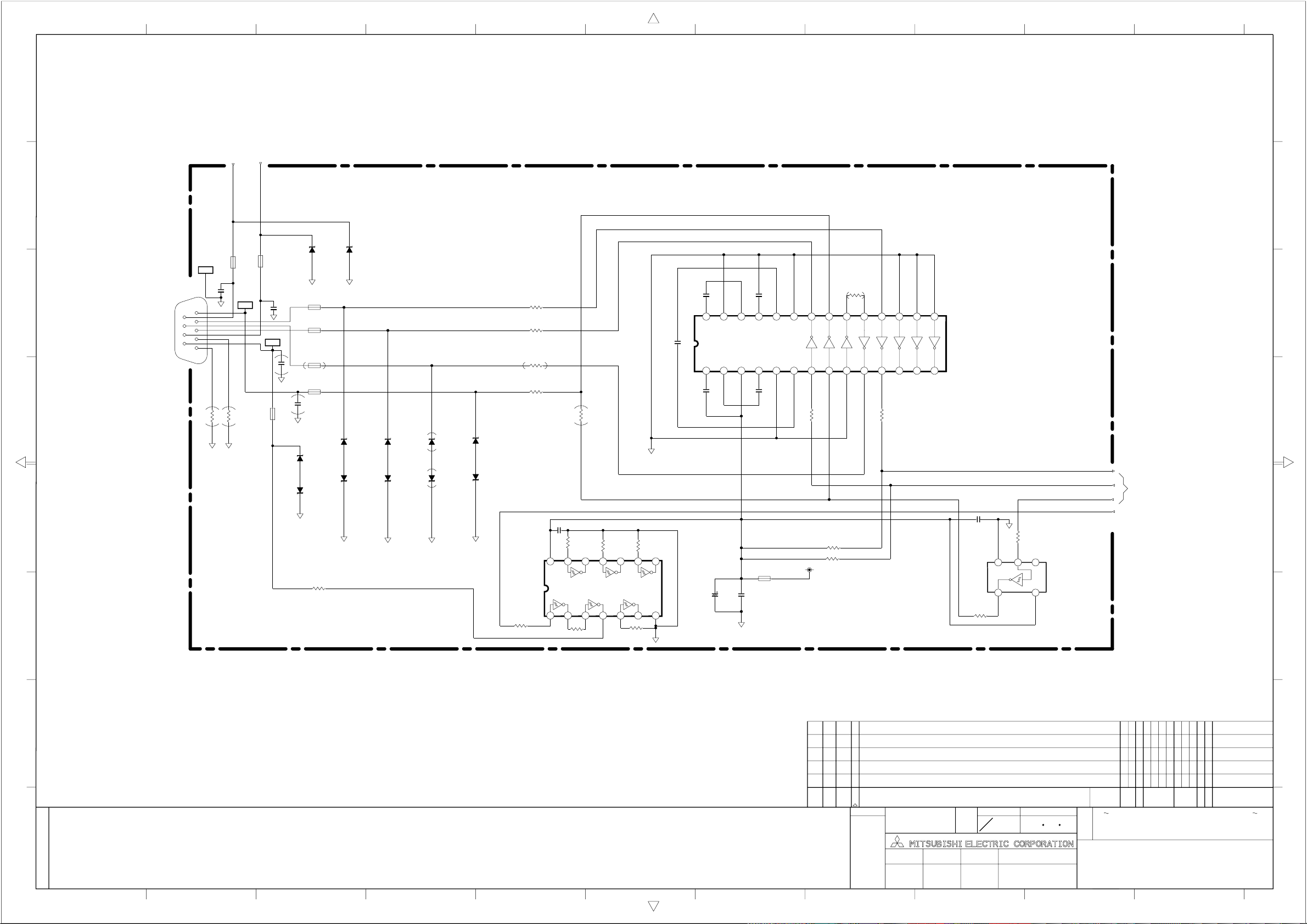
2345678910111
a
KEY1
KEY0
b
D7X7 D7X8
UDZS9.1B UDZS9.1B
L7X5
BK2125HS750
L7X6
GND2
C7X8
K-.01
J7X0
DT10121-R3T-4F
CN MD9P
c
d
1
6
2
7
3
8
4
9
5
0
R7Y8
DG DG
e
f
BK2125HS750
DG DG
L7X1
DG
LCD-RMC
C7X7
K-.01
DG
L7X8
BK2125HS750
C7Y3
39P
C7Y2
39P
DG
DG
BK2125HS750
L7X2
BK2125HS750
L7X3
BK2125HS750
L7X7
BK2125HS750
D7Y1
UDZS12B
D7Y2
UDZS12B
R7Y7
1/16W
1K
D7X1 D7X2 D7X3
UDZS12B UDZS12B UDZS12B
D7X5 D7X6 D7X4
UDZS12B UDZS12B UDZS12B
DG
DG DG
D7Y3
UDZS12B
D7Y4
UDZS12B
DG
R7Y6
STB-RMC
DG
0
R7Y9
R7X1
100
1/16W
R7X2
100
1/16W
R7X3
100
1/16W
R7Z1
100
1/16W
R7Y0
0
1/16W
C7Y1
K-.1
100
R7Y1
1/16W
VDD
IC7X1
74LCX14MTCX_NL
1234567
1001/16W
R7Y5
100
R7Y2
1/16W
1001/16W
1/16W
R7Y4
DG
R7Y3
100
1/16W
891011121314
100
C7X2
25V
1u
C7X6
25V
1u
C7X4 C7X5
25V
1u
VSS
DG
28
C3+
1V+2
C7X3
25V
1u
24
25
26
27
GND
C2+3VCC4C2-5CM6C1+
C7X0
16V
47u
V-
C7X1
K-.01
25V
1u
L7X4
BLM21P221SG
C1-
C3-
DG
SHDN
T1
7 8 9 10 11 12 13 14
R7X6
100
1/16W
S3.3V
R7X7
0
1/16W
151617181920212223
R1
R2
R3
R7X5
100
1/16W
R4
T2
T3
R5
IC7X0
ADM3311EARS
RXDO
TXDO
CON
μ
R7X9
10K
1/16W
R7X8
10K
1/16W
C7Y4
K-.1
R7X0
100
1/16W
DG
VSS
45
R7X4
100
1/16W
1NC23
VDD
IC7X2
TC7SH14F
STB_RMC
LCD_RMC
a
b
c
d
e
f
g
CHANGE
改定
g
LT-3780D2
改番
CHANGE
MARK
32 33 34 35
副番 品番
SUB
ITEM
ITEM
LT-3280D1
標
マ
|
ク
*
出図先 尺度 作成日付
規格
第3角法
CAD
3RD ANGLE
PROJECTION
作成 照査 設計 検認
DRAWN CHECKED DESIGNED
本間 千原 石畑
DIM
MATERIAL
SCALE
IN
mm
NTS
AND DIMENSIONS
2005 7 11
APPROVED
DATE
図
名
880A647
69 70 71 7972 73 74 75 76 77 78 80
C
(MI)
MARK
5
RS232C(MAIN)
O
UNIT
C
O
CODE
M
REVISION NO.
TITLE OF DRAWING
SCHEMATIC-DIAGRAM
25 26 27 28 29 30 31
APP. FROM
改
理同期
**
摘要
REMARK
(3/14)
24
2345678910111
SCL=1/1
Page 50

FROIS2
2345678910111
TO
μ
CON
TO
用
I/F
PC
a
b
c
Dsub15
1
2
3
4
5
6
DV11201-P33-4F
7
8
9
10
11
J200
12
13
14
15
L200
BLM21B050SPT
R
L201
BLM21B050SPT
G
L202
BLM21B050SPT
B
GND
GND
GND
GND
GND
NC
GND
GND
SDA
H
V
SCL
R210
F-2.2K
1/10W
d
e
TPPCV
R200
F-75 1/4W
R201
F-75 1/4W
R202
F-75 1/4W
L203
BK2125HS431
D202
UDZS9.1B
TPPCR
TPPCG
TPPCH
TPPCB
L204
BK2125HS431
R211
F-2.2K
1/10W
R203
10 1/10W
R204
10 1/10W
R205
10 1/10W
R208
100
1/16W
R209
100
1/16W
D203
UDZS9.1B
S5V
L205
BLM21P221SG
IC200
24LC21ATI/SN
A0
VCC
S5V
R207
R206
4.7K
4.7K
1/16W
1/16W
D200
UDZS9.1B
D201
UDZS9.1B
R213
100
1/16W
R212
100
1/16W
100
1/16W
R219
100
1/16W
R220
R215
100
1/16W
R216
100
1/16W
100
1/16W
R223
R224
100
1/16W
100
1/16W
R225
IC201
74LCX14MTCX_NL
1
2
O0
I1
3
4
O1
5
I2
6
O2
GND
7
IC202
SN74LVC08APWR
1
A0
2
B0
O0
3
A1
4
B1
5
6
O1
7
GND
1
A1
2
A2
3
GND
45
14
VccI0
I5
13
R218
100
1/16W
12
O5
11
I4
O4
10
R217
100
1/16W
I3
9
O3
8
14
VCC
R230
100
1/16W
13
A2
R229
100
1/16W
12
B2
O2
11
R228
0
1/16W
A3
10
R227
0
1/16W
B3
9
R226
0
1/16W
O3
8
SCL
SDA
L206
BLM21P221SG
C201
25V
1M
8
7
6
C200
K-.01
BLM21P221SG
C202
R260
25V
10K
1M
1/16W
DDC_WP
DDC_SCL
DDC_SDA
GND3
D3.3V
1234
L211
BLM21P221SG
C240
16V
K-.1
DG
D208
1SS355TE17
D209
1SS355TE17
C203
25V
K-.047
R262
47K
1/16W
R263
47K
1/16W
D204
1SS355TE17
D205
1SS355TE17
C205
25V
K-.047
C206
25V
K-.047
IC204
TC74VCX74FT
1
-CD1
D1
2
CP1
3
-SD1
4
Q1
5
-Q1
6
GND
7
R214
10K
1/16W
S3.3V
L207
D206
1SS355TE17
D207
1SS355TE17
C204
1000
CH
VCC
14
-CD2
13
5678
D2
12
CP2
11
R264
-SD2
47k
1/16W
10
R265
Q2
9
47K
1/16W
-Q2
8
DG
AD3.3V
R259
0
L208
FLC32CT-100K
C209
C236
C211
C237
C238
C239
C215
R254
47K 1/16W
R255
47K 1/16W
R231
100 1/16W
R232
100 1/16W
1/16W
R261
0
1/16W
R253
0
1/16W
K-.116V
K-.0150V
K-.116V
K-.0150V
K-.0150V
K-.0150V
K-.116V
C207
16V
K-.1
C208
16V
47u
C210
K-.116V
C212
K-.116V
C213
K-.116V
C214
K-.116V
C216
K-.116V
C217
16V
K-.1
AD3.3V
L209
10u
C218
25V
220u
C219
50V
K-.01
f
PC_HSI
TO
PC_VSI
μ
ENABLE
CON
SI_QDE
TO
SI_QV
FROIS2
SI_QH
A3.3V_SCL
A3.3V_SDA
μ
CON
TO
g
1
2
3
4
5
6
7
8
9
10
11
12
13
14
15
16
17
18
19
20
21
22
23
24
25
26
27
28
29
30
31
32
33
34
35
36
37
38
C220
16V
K-.1
R258
3.3V
REF BYPASS
GND
GND
BULE0
3.3V
3.3V
BLUE1
RMIDSCV
3.3V
GND
SOG0
GREEN0
3.3V
GND
SOG1
GREEN1
3.3V
GND
RED0
3.3V
GND
RED1
BMIDSCV
3.3V
3.3V
GND
GND
CKINV
CLAMP
SDA
SCL
A0
3.3V
GND
GND
3.3V
P3.3
P3.3
39
FR_VS
0
1/16W
GND
VSOUT
GND
40 41 42 43
FR_HS
FR_CLK
FR_OB0
FR_OB1
FR_OB2
D3.3V
HSYNC0
1234
GND
OB0
GND
P3.3
C221
5678
GND
P3.3
K-.116V
C225
8200P
16V
R249
4S600
1/16W
C235
R251
0 1/16W
16V
K-.1
0 1/16W
R252
HS600 1/16W
R250
124125126127128
CLK
HSOUT
CLKINV
SOGOUT
GND
VSYNC1
HSYNC1
VSYNC0
44
45 46 47 48 495051 52 53 54 55 56 57 58
R234
R233
R257
R256
100 1/16W
100 1/16W
47K 1/16W
47K 1/16W
FR_OB6
FR_OB5
FR_OB4
FR_OB3
5678
1234
IC203
AD9888KSZ-170
GND
P3.3
FILT
COAST
R237
10K 1/16W
R236
K-.116V
C223
F-4.7K
R235
1/16W
C226
C245
.047
16V
.015
16V
FR_OB7
C234
16V
K-.1
OB7
CKEXT
10K 1/16W
R238
4S600
1/16W
R248
4S600 1/16W
R247
D3.3V
GND
C224
FR_EB0
1234
4S600 1/16W
GND
D3.3V
K-.116V
1234
FR_ER7
EB0
ER7
FR_EB4
FR_EB3
FR_EB2
FR_EB1
5678
1234
109110111112113114115116117118119120121122123
59 60 61 62 63 64
5678
1234
FR_ER6
FR_ER5
FR_ER4
FR_ER3
FR_EB5
FR_ER2
FR_EB6
FR_ER1
FR_EB7
5678
103104105106107108
D3.3V
D3.3V
D3.3V
D3.3V
D3.3V
5678
EB7
GND
GND
GND
OG0
OG7
GND
EG0
EG7
GND
OR0
OR7
GND
GND
GND
GND
ER0
FR_ER0
FR_OB[7-0]
FR_EB[7-0]
AD3.3V
L210
BLM21P221SG
R246
4S600
1/16W
C232
16V
47u
C233
16V
K-.1
DG
TO
FROIS2
a
DG
b
C231
16V
102
101
100
99
98
97
96
95
94
93
92
91
90
89
88
87
86
85
84
83
82
81
80
79
78
77
76
75
74
73
72
71
70
69
68
67
66
65
K-.1
C230
K-.116V
1234
C229
K-.116V
C228
K-.116V
C227
K-.116V
R244
1234
R242
1234
R240
4S600
4S600
4S600
1/16W
1/16W
1/16W
5678
5678
5678
R245
4S600 1/16W
1234
R243
4S600 1/16W
1234
R241
4S600 1/16W
1234
5678
5678
5678
FR_OG0
FR_OG1
FR_OG2
FR_OG3
FR_OG4
FR_OG5
FR_OG6
FR_OG7
FR_EG0
FR_EG1
FR_EG2
FR_EG3
FR_EG4
FR_EG5
FR_EG6
FR_EG7
FR_OR0
FR_OR1
FR_OR2
FR_OR3
FR_OR4
FR_OR5
FR_OR6
FR_OR7
FR_OG[7-0]
FR_EG[7-0]
FR_OR[7-0]
TO
FROIS2
c
d
e
f
R239
4S600
1/16W
FR_ER[7-0]
TO
FROIS2
g
CHANGE
改定
LT-3780D2
改番
副番 品番
CHANGE
MARK
ITEM
1 LT-3280D
32 33 34 35
標
マ
|
SUB
ク
ITEM
*
出図先 尺度 作成日付
DIM
MATERIAL
SCALE
IN
mm
NTS
規格
第3角法
CAD
3RD ANGLE
PROJECTION
作成 照査 設計 検認
DRAWN CHECKED DESIGNED
本間 千原 石畑
AND DIMENSIONS
2005 7 11
APPROVED
DATE
図
名
69 70 71 7972 73 74 75 76 77 78 80
C
(MI)
MARK
5
AD(MAIN)
O
UNIT
C
O
CODE
M
REVISION NO.
TITLE OF DRAWING
SCHEMATIC-DIAGRAM
APP. FROM
改
理同期
**
摘要
REMARK
(4/14)
25 26 27 28 29 30 31
880A647
24
2345678910111
SCL=1/1.2
Page 51

GND
2.5V
MTEST
PLLEN
OB0
OB1
OB2
OB3
OB4
OB5
OB6
OB7
EB0
EB1
EB2
EB3
2.5V
GND
3.3V
EB4
EB5
EB6
EB7
OG0
OG1
OG2
OG3
OG4
OG5
OG6
OG7
2.5V
GND
3.3V
EG0
EG1
EG2
EG3
EG4
EG5
EG6
EG7
2.5V
GND
C2A7
16V
K-.1
L2A1
10u
C2F0
10V
10u
DG
C2E9
16V
K-.1
TO ADC
FR_CLK
174
175
176
DCLK
3.3V
VDDP2
D3
3.3V46GND47OR048OR149OR2
45
FR_OR0
μ
CON
TO
FR_VS
FR_HS
10u
10V
K-.1
C2E7
C2E8
16V
DGDG
10K
R2E0
170DH171
172DE173
DV
VSSP2
L2A2
10u
R2C9
100
1/16W
FR_CNT
R2E1
10
1/16W
C2E6
16V
K-.1
164
165
166
167
168
169
RSTN
VDDPB
GND
3.3V
SCLK
VSSPB
D0
D1
D2
D4
OR351OR452OR553OR654OR755ER056ER157ER258ER359ER460ER561ER662ER7632.5V
50
FR_OR7
FR_OR5
FR_OR4
FR_OR3
FR_OR2
FR_OR1
FR_OR6
FR_ER0
FR_ER1
FR_ER2
FR_RSTN
1234
163
2.5V
FR_ER3
FR_MSN
162
D5
FR_ER4
MSN
FR_MST
161
FR_ER5
FR_MSQ
FR_MSD
MST
5678
160
MSQ
FR_ER6
C2E5
10K
R2C5
156
K-.1
16V
C2A9
16V
K-.1
10K
R2C4
155
QLCOPOW1
QLCOPOW2
IC2A0
M66471FP
FROIS2
C2E4
16V
K-.1
152
153
154
GND
2.5V
1234
SEB0
R2C8
100X4
1/16W
10K
10K
R2C6
R2C7
157
158
159
MSD
QPOWSAVE
QINVCONT
GND653.3V66PHCLK67GND683.3V69QOR070QOR171QOR272QOR3732.5V74GND75GND763.3V77QOR4
64
K-.1
16V
C2A8
FR_ER7
151
GND
1234
3.3V
SEB1
SOR7
SOR6
SOR5
SOR4
SOR3
SOR2
SOR1
SOR0
SOG7
SOG6
SOG5
SOG4
1234
138
QOB7
3.3V
1234
SEG0
R2C0
4S600
1/16W
5678
134
135
136
137
QOB4
QOB5
QOB6
5678
R2A2
4S600
1/16W
SEG1
SEG2
SEG3
R2C2
4S600
1/16W
5678
C2E3
16V
K-.1
145
146
147
148
149
150
GND
QEB4
QEB5
QEB6
QEB7
K-.1
16V
K-.1
16V
C2C1
C2C0
5678
R2A0
4S600
1/16W
SEB2
SEB3
R2C1
4S600
1/16W
5678
1234
C2E2
16V
K-.1
139
140
141
142
143
144
GND
QEB0
QEB1
QEB2
QEB3
3.3V
QOR579QOR680QOR781GND823.3V83QER084QER185QER286QER387GND883.3V
78
5678
R2A1
4S600
1/16W
1234
SEB4
SEB5
SEB6
SEB7
D3.3V
L2A3
BLM21P221
C2C9
16V
K-.1
DG
C2E1
16V
K-.1
133
GND
3.3V
132
GND
131
2.5V
130
QOB3
129
QOB2
128
QOB1
127
QOB0
126
3.3V
125
GND
124
QEG7
123
QEG6
122
QEG5
121
QEG4
120
3.3V
119
GND
118
QEG3
117
QEG2
116
QEG1
115
QEG0
114
3.3V
113
GND
112
QCLK
111
QDE
110
QH
109
QV
108
GND
107
2.5V
106
QOG7
105
QOG6
104
QOG5
103
QOG4
102
3.3V
101
GND
100
QOG3
99
QOG2
98
QOG1
97
QOG0
96
3.3V
95
GND
94
QER7
93
QER6
92
QER5
91
QER4
90
2.5V
89
GND
K-.1
16V
C2C2
16V
C2C8
K-.1
16V
C2C7
K-.1
16V
C2C6
K-.1
16V
C2C5
K-.1
16V
C2C4
K-.1
16V
C2C3
K-.1
SOG3
SOG2
SOG1
SOG0
SOB5
SOB4
SOB3
SOB2
SOB1
SOB0
ADC
TO
C2E0
16V
47u
DG
R2A9
4S600
1/16W
1234
5678
R2A8
4S600
1/16W
1234
R2A7
4S600
1/16W
1234
R2A5
4S600
1/16W
1234
R2A4
4S600
1/16W
1234
R2A3
4S600
1/16W
1234
DG
5678
5678
5678
5678
5678
SOB7
SOB6
SOB5
SOB4
SOB3
SOB2
SOB1
SOB0
SI_QV
SI_QH
SER7
SER6
SER5
SER4
SER3
SER2
SER1
SER0
SEG7
SEG6
SEG5
SEG4
SI_QDE
R2K0
HS600
R2K1
HS600
R2K2
33
R2K3
HS600
SEG7
SEG6
A3.3V
C2G2
R2G0
R2G1
R2G2
C2G3
R2G3
SER7
SER6
SER5
SER4
SER3
SER2
SER1
SER0
C2G4
16V
K-.1
L2A7
10u
C2G5
16V
K-.1
A3.3V
L2A4
BLM21P221
C2G1
C2G0
16V
16V
47u
K-.1
DGDG
HSYNC
76
VSYNC
77
DE
78
GND
79
IDCK
16V
K-.1
47K
16V
K-.1
10K
DG
80
I3.3V
81
CTL3
82
47K
47K
CTL2
83
CTL1
84
P3.3V
85
GND
86
RSVD
87
3.3V
88
GND
89
ER7
90
ER6
91
ER5
92
ER4
93
ER3
94
ER2
95
ER1
96
ER0
97
I3.3V
98
EG7
99
EG6
100
EG52EG43EG34EG25EG16EG07GND83.3V9EB710EB611EB512EB413EB314EB215EB116EB017I3.3V18P3.3V19GND20RSVD21RSVD22RSVD23RSVD24EDGE25PIXS
1
C2G6
10V
10u
DG
SEG0
SEG1
SEG2
SEG3
SEG4
SEG5
SOG0
SOG1
SOG2
SOG3
SOG4
SOG5
SOG6
SOB7
SOB6
K-.1
16V
C2H8
66
67
GND68OB769OB670OB571OB472OB373OB274OB175OB0
I3.3V
IC2A1
SII160CTG100
K-.1
16V
C2G7
SEB3
SEB4
SEB5
SEB6
SEB7
SOG7
C2H5
C2H6
16V
16V
47u
K-.1
DGDGDG
K-.1
16V
C2H7
56
57
GND58OG759OG660OG561OG462OG363OG264OG165OG0
10K
R2G4
K-.1
16V
K-.1
16V
R2G5
C2G9
C2G8
SEB0
SEB1
SEB2
51
3.3V
10K
OR452OR353OR254OR155OR0
OR5
OR6
OR7
GND
TX2+
TX2-
A3.3V
TX1+
TX1-
GND
TX0+
TX0-
A3.3V
GND
A3.3V
TXC+
TXC-
GND
EXT_SWING
GND
3.3V
RSVD
RSVD
RSVD
PD
10K
10K
10K
R2G9
R2G8
R2H0
R2G7
10K
R2G6
10K
A3.3V
L2A5
BLM21P221
a
SOR0
SOR1
SOR2
SOR3
SOR4
50
49
48
47
46
45
44
43
42
41
40
39
38
37
36
35
34
33
32
31
30
29
28
27
26
C2H4
16V
C2H3
K-.1
R2H4
F-680
16V
C2H2
K-.1
10K
R2H3
R2H2
10K
10K
R2H1
A3.3V
SOR5
SOR6
SOR7
0
R2J2
1/16W
PC_TX2+
0
1/16W
0
1/16W
0
1/16W
0
1/16W
0
1/16W
0
1/16W
0
1/16W
PC_TX2-
PC_TX1+
PC_TX1-
PC_TX0+
PC_TX0-
PC_TXC+
PC_TXC-
SI16PD
R2J1
16V
K-.1
R2J0
R2H9
R2H8
R2H7
R2H6
R2H5
R2J3
100
1/16W
b
c
TO
GENESIS
d
TO
μ
CON
e
10u
C2H0
16V
K-.1
DG
L2A6
C2H1
C2H9
10V
16V
10u
47u
DG
DG
DG
f
2345678910111
D2.5V
a
L2A0
BLM21P221
DG
C2F1
C2A0
16V
47u
K-.1
16V
b
16V
C2A1
K-.1
FR_OB0
FR_OB1
FR_OB2
FR_OB3
FR_OB4
FR_OB5
FR_OB6
FR_OB7
c
FR_OB[7-0]
FR_EB[7-0]
d
TO
ADC
FR_OG[7-0]
e
FR_EG[7-0]
DG
f
TO
ADC
FR_OR[7-0]
FR_ER[7-0]
C2J8
10
CH
FR_EB0
FR_EB1
FR_EB2
FR_EB3
FR_EB4
FR_EB5
FR_EB6
FR_EB7
FR_OG0
FR_OG1
FR_OG2
FR_OG3
FR_OG4
FR_OG5
FR_OG6
FR_OG7
FR_EG0
FR_EG1
FR_EG2
FR_EG3
FR_EG4
FR_EG5
FR_EG6
FR_EG7
IC2C1
XC2164C51TMR(fo/4)
1
Q0
/INH
2
VSS
VDD
34
/XT
XT
X2J1
24.576M
SMD-49
DG
16V
C2A2
K-.1
16V
C2A3
K-.1
16V
C2A4
K-.1
16V
C2A5
K-.1
16V
C2A6
K-.1
D3.3V
R2J8
10K
6
5
L2J1
BLM21P221
C2J6
16V
K-.1
DG
C2J7
10
CH
1
2
3
4
5
6
7
8
9
10
11
12
13
14
15
16
17
18
19
20
21
22
23
24
25
26
27
28
29
30
31
32
33
34
35
36
37
38
39
40
41
42
43
44
g
CHANGE
改定
g
LT-3780D2
LT-3280D1
改番
CHANGE
MARK
32 33 34 35
副番 品番
SUB
ITEM
ITEM
標
マ
|
ク
*
出図先 尺度 作成日付
規格
3RD ANGLE
第3角法
PROJECTION
作成 照査 設計 検認
DRAWN CHECKED DESIGNED
CAD
本間 千原 石畑
DIM
MATERIAL
SCALE
IN
mm
NTS
AND DIMENSIONS
DATE
2005 7 11
APPROVED
69 70 71 7972 73 74 75 76 77 78 80
C
(MI)
UNIT
MARK
CODE
5
図
FROIS2(MAIN)
名
SCHEMATIC-DIAGRAM
O
C
O
M
REVISION NO.
TITLE OF DRAWING
APP. FROM
改
理同期
**
摘要
REMARK
(5/14)
25 26 27 28 29 30 31
880A647
24
2345678910111
SCL=1/1.2
Page 52

CON
μ
CON
μ
CON
μ
2345678910111
a
b
c
DD/CEC/GND
d
e
f
g
CHANGE
改定
HP_DETECT
DSCL
N.C.
CEC
RXC-
Clock_
Shield
RXC+
RX0-
Data0_
Shield
RX0+
RX1-
Data1_
Shield
RX1+
RX2-
Data2_
Shield
RX2+
+5V
DSDA
S3.3V
R565
820-F
100
R500
R501
1/4W
180
DC1R019JDA
J500
HDMI_CONNECTOR
12345678910111213141516171819
DG
DG
DG
DG
HDMI_DTC
Q500
DTC124EK
VR501
AVRL161A1R1N
DG
D501
UDZS9.1B
DG
D502
UDZS9.1B
D503
UDZS9.1B
DG
R502
OPEN
1234
NC
NC
NC
GND
IC501
24LC22ATI/SN
2345678910111
DDC_WP
100
R503
L500
BLM21P221PG
VCC
VCLK
SCL
5678
SDA
C500
10V
10u
DG
ACM2012D-900-2P
ACM2012D-900-2P
ACM2012D-900-2P
ACM2012D-900-2P
R508
12
12
S5V
R504
OPEN
47K
47K
R506
R507
100
R509
100
L510
34
L511
34
L512
12
34
L513
12
34
DTC124EK
R563
10K-F
R564
DG
Q501
UPA672T-T1-A
D2
4S25G26
VR502 VR503 VR504
AVRL161A1R1N AVRL161A1R1N AVRL161A1R1N AVRL161A1R1N
DG
VR506 VR507 VR508 VR509
AVRL161A1R1N AVRL161A1R1N AVRL161A1R1N AVRL161A1R1N
1
2
34
R524
0
Q502
DG
HDMI5V
18K-F
C546
K-.01
DG
1S12G13
D1
DG
D
D
GS
IC502
SI3457DV
R523
10K
HDMI_ON
CON
μ
L501
10u
C502
100u
DG
16V
R511
R513
10
DSDA
DG DG
C520
K-.01
S3.3V
R731
0
DSCL
4.7K
VR505
R512
10
HD3.3V
L504
10u
C521 C522
16V
100u
DGDG
DG
R510
4.7K
DGDG
D
6
D
5
CSDA CSCL
+3.3VA
10u
L502
10u
50V
K-.1
C505
C506
3.3V_HDMI
16V
100u
R562
10K
R561
Q504
C3052
GND4
DG
R560
100
4.7K
C507
25V
1000P
DGDGDG
Q503
NDC7002N
4.7K
R559
4
D2
5
S1
6
D1
C512
CH
100
BLM21P221PG
IC503
SN74LVC08APWR
1
A0
2
B0
3
Q0
4
A1
5
B1
6
Q1
7
GND
DG
C514
G2
C510
0
R558
3
S2
2
G1
1
R556
0
76
77
78
79
80
R514
F-390
81
C509
C508
K-.1
100CH
82
83
84
85
86
87
88
89
90
C511
100CH
K-.1
91
92
C513
K-.1
93
94
C515
K-.1
C516
95
96
97
98
99
100
100 CH
K-.1
C517
14
VCC
A2
13
12
B2
11
Q2
A3
10
B3
9
Q3
8
100CH
L508
HDMIMUTE_EN
CON
μ
SI99RST
S3.3V_SDA
S3.3V_SCL
SI99RST
0
0
R549
R548
47K
R547
4.7K
R557
4.7K
R551
0
R555
CSCL
CSDA
DSDA
DSCL
DGND
PGND1
PVCC
EXT_RES
AVCC
RXC-
RXC+
AGND
RX0-
RX0+
AGND
AVCC
AGND
RX1-
RX1+
AVCC
AGND
AVCC
RX2-
RX2+
AGND
GND
VCC
BLM21P221PG
RSVDL
DACVCC
DACGND
N/C
12345678910111213141516171819202122232425
D3.3V
L509
C545
K-.1
DG
DG
MUTE_MAIN
MUTE_MAIN1
R545
33
R546
RESET#
N/C
HDMI_PB0
1234
100
10K
R550
INT
DACGNDR
HDMI_PB2
HDMI_PB1
Q1
Q0
DACVCCR
AnRPr
C523 C524
50V K-.01
10u
F-75
R526
1/10W
DG
5678
C543
C544
Q2
COMP
R527
HDMI_PB3
100 CH
K-.1
OVCC
REST
F-18
R525
F-75
1/10W
HDMI_PB4
1234
GND
OGND
DACVCCG
DACGNDG
F-75
R528
1/10W
HDMI_PB5
VCC
AnGY
HDMI_PB6
HDMI_PB7
5678
C541
100 CH
K-.1
C542
IC500
SII9993CTG100
DACGNDB
DACVCCB
R529
1/10W
F-75
R544
AnBPb
C525
33
100 CH
HDMI_PB(7:0)
HDMI_Y0
1234
Q8
Q7Q6Q5Q4Q3
GND
VCC
RSVDL
R530
K-.1
C526
L505
10u
C529
1000
25V
HDMI_Y2
HDMI_Y1
OGND
PSVD0
C527
100 CH
4.7K
C528
K-.1
C530
K-.1
改番
CHANGE
MARK
HDMI_Y3
5678
100 CH
C539
K-.1
C540
OVCC
PSVD0
32 33 34 35
副番 品番
SUB
ITEM
CON
μ
AUDIO
Q9
OVCC
R543
33
51525354555657585960616263646566676869707172737475
Q13
Q12
Q11
Q10
PGND2
C531
10u
50V
DG
Q14
50
Q15
49
Q16
48
OVCC
47
ODCK
46
OGND
45
Q17
44
Q18
43
Q19
42
GND
41
VCC
40
Q20
39
Q21
38
Q22
37
Q23
36
DE
35
VSYNK
34
HSYNK
33
SCK
32
WS
31
SDO
30
29
28
27
26
C533
10u
10V
第3角法
R533
規格
3RD ANGLE
PROJECTION
SPDIF
OGND
MCLKIN
MCLKOUT
PVCC2
PLLIN
N/C
R531
F-3.9K
C532
0.047u
25V
LT-3780D
2
LT-3280D
1
標
マ
|
ク
ITEM
*
出図先 尺度 作成日付
100 CH
C534
100 CH
OPEN
R532
C536
C537
K-.1
C535
K-.1
33
DIM
IN
mm
a
b
R542
33
1234
HDMI_Y4
HDMI_Y5
HDMI_Y6
L506
5678
33
C538
OPEN
DG
R541
33
1234
L507
HDMI_Y7
0
HDMI_Y(7:0)
HDMI_CLK
c
HDMI_PR0
HDMI_PR1
HDMI_PR2
HDMI_PR3
5678
R540
33
1234
5678
HDMI_PR4
HDMI_PR5
HDMI_PR6
HDMI_PR7
d
HDMI_PR(7:0)
33
R539
R538
R537
33
33
HDMI_DE
HDMI_VS
HDMI_HS
GM1601
uCON
e
R536
33
33
R535
R534
33
33
R552
DG
HDMI_SCK
HDMI_WS
HDMI_I2S
HDMI_MCLK
AUDIO
DIGITAL
OUTPUT
f
g
69 70 71 7972 73 74 75 76 77 78 80
C
MATERIAL
SCALE
NTS
AND DIMENSIONS
2005 7 11
DATE
(MI)
UNIT
CODE
MARK
5
図
HDMI(MAIN)
名
SCHEMATIC-DIAGRAM
O
C
O
M
REVISION NO.
TITLE OF DRAWING
APP. FROM
改
理同期
**
摘要
REMARK
(6/14)
24
25 26 27 28 29 30 31
作成 照査 設計 検認
DRAWN CHECKED DESIGNED
CAD
本間 千原 石畑
APPROVED
880A647
SCL=1/1
Page 53

21 345678910111213141516
1
2
4
8
7
5
C450
K-.1
C453
K-.1
L402
BLM21PG221SN1D
B1+
/E_B2
E_B3
(
(
0
R461
R462
R456
/37":B1-
32":NC
GND5
R4A7
3
4
6
5
HDMI_PR7
HDMI_PR6
HDMI_PR5
HDMI_PR4
47K
47K
R437
R438
D_CLP
SD_DE
C404 C403
K-.1 K-.1 K-.1
L400
BLM21PG221SN1D10u
C401
10V
10u
D1.8V
C446
K-.1
C447
10V
10u
C455
K-.1
C421
10V
10u
R450
3.3K
C422
K-.1
/E_B5
/E_B7
B0-
B1-
/E_B4
/E_B6
B0+
47K
R4L8
O_R3
O_R2
37"
000
R465
R464
R463
R457
1920212223242526
CNF1
A3+
GND
/37":B0+
32":NC
/37":B0-
32":NC
HDMI_PR3
HDMI_PR2
D3.3V
C400
K-.1
L405
BLM21PG221SN1D
O_R0
O_R1
R467
FI_W41P-HF
A3-
HDMI_HS
HDMI_PR[7:0]
HDMI_PR1
HDMI_PR0
C419
6.3V
470u
D2.5V
C471
K-.1
/O_R4
/O_R5
A3+
A3-
P_HD
P_VD
(((
47K047K
(
AC+
HDMI_DE
R468
AC-
HDMI_VS
HDMI_CLK
47K
R4L7
D_0DD
C461
K-.1
L410
BLM21PG221SN1D
C418
K-.1
/O_R6
/O_R7
/O_G1
A2+
AC-
AC+
R470
47K
A2+
HDMI_Y7
HDMI_Y6
C472
10V
10u
/O_G2
A2-
A2-
HDMI_Y5
HDMI_Y4
C475
K-.1
C477
K-.1
C480
K-.1
C482
K-.1
C484
K-.1
C486
K-.1
/O_G4
A1+
1234
12131415161718
A1+
HDMI_Y3
HDMI_Y2
C473
/O_G5
A1-
A1-
HDMI_Y1
5678
/O_G6
A0+
HDMI_Y[7:0]
HDMI_Y0
HDMI_PB7
HDMI_PB6
C4A3
K-.1
C4A4
K-.1
/O_G7
A0-
A0+
A0-
HDMI_PB5
R4L3
HDMI_PB3
HDMI_PB4
R4L5
GND
HDMI_PB2
0
R471
0
0
HDMI_PB1
HDMI_PB0
0
R472
ODSEL2
0
R473
0
R474
R4L2
R4L4
ODSEL1
0
0
R476
R477
OPEN
OPEN
567891011
NC
R4A5
R420
PC_TX0+
PC_TX1-
PC_TX2-
PC_TX1+
PC_TX2+
a
PC_TXC-
PC_TX0-
PC_TXC+
47K 47K
R419
R418
F-510
F-12K
R417
F-510
1
2
3
4
8
7
6
5
R4A6
47K
47K
1
1
2
2
3
3
4
8
8
7
7
6
6
5
IC400
gm1601-LF-CF
b
R412
10K
R407
10K
R408
10K
R403
c
H8S_INT
GMRST
d
e
GEN_W
S3.3V
1234567
SDA
SCL
B7B-PH-K-S
GND
GEN_W
S5V
MS2
Reserved
OCM_WE
OCM_RE
OCM_CS
f
g
OCM_ADR[19:0]
L411
BLM21PG221SN1D
L413
S3.3V
OCM_ADR19
OCM_ADR18
OCM_ADR17
OCM_ADR16
OCM_ADR15
OCM_ADR14
OCM_ADR13
OCM_ADR12
OCM_ADR11
OCM_ADR10
OCM_ADR9
OCM_ADR8
OCM_ADR7
OCM_ADR6
OCM_ADR5
OCM_ADR4
OCM_ADR3
OCM_ADR2
OCM_ADR1
OCM_ADR0
S5V
BLM21PG221SN1D
C4A7
K-.1
C4A0
K-.1
(
(
10V
10u
C4A8
K-.1
47K
R4K2
R4K3
1234
R4A0
47
1234
R4A1
47
1234
R4A2
47
1234
R4A3
47
1234
R4A4
47
1234
R423
47K
1234
R424
47K
47K
GM_RXD
GM_TXD
GEN_INT
5678
5678
5678
5678
5678
5678
5678
D3.3V
R4M0
OPEN
14.318M
R4M2
SMD-49
OPEN
R4M3R4M1
OPENOPEN
GMRST
100
R429
100
R430
47K
R425
47K
R426
C498
K-.01
R406
10K
K-.01
C495
K-.01
C496
10K
R402
C493
C490
CH
33P
R4M7
560
X400
C491
CH
39P
R4K1R4K0C4A1
10K10K
47K
R414
(
(
R421
47K
47K
R422
K-.01
C4K6
K-.1
1234
R4K6
R4K7
D3.3V
OCM_DAT15
OCM_DAT14
OCM_DAT13
OCM_DAT12
OCM_DAT11
OCM_DAT10
OCM_DAT9
OCM_DAT8
R4M4
0
5678
47K
47K
C492
R4M5
0
IC402
CY25811SXC(T)
R427
R428
R400
R401
10K
R411
10K
h
OCM_DAT4
OCM_DAT5
OCM_DAT7
OCM_DAT6
i
j
C4K5
K-.1
53261-0690
CNF2
/53261-0671(LF)
GND
GND
GND
PANEL18V
18V
123456
PANEL18V
37"
BLM21PG221SN1D
L415
PANEL18V
OCM_DAT[7:0]
CHANGE
A1 A2 A3 A4 A5 A6 A7 A8 A9 A10 A11 A12 A13 A14 A15 A16 A17 A18 A19 A20 A21 A22 A23 A24 A25 A26
C445
K-.1
C497
K-.01
AD_B-
B1 B2 B3 B4 B5 B6 B7 B8 B9 B10 B11 B12 B13 B14 B15 B16 B17 B18 B19 B20 B21 B22 B23 B24 B25 B26
AD_B+
C494
K-.01
AD_G-
C1 C2 C3 C4 C5 C6 C7 C8 C9 C10 C11 C12 C13 C14 C15 C16 C17 C18 C19 C20 C21 C22 C23 C24 C25 C26
AD_G+
SOG
K-.01
AD_R-
D1 D2 D3 D4 D5 D6 D7 D8 D9 D10 D11 D12 D13 D14 D15 D16 D17 D18 D19 D20 D21 D22 D23 D24 D25 D26
AD_R+
E1 E2 E3 E4 E23 E24 E25 E26
F1 F2 F3 F4 F23 F24 F25 F26
G1 G2 G3 G4 G23 G24 G25 G26
R4M6
OPEN
H1
C430
K-.1
J1 J2 J3 J4 J23 J24 J25 J26
C431 C432
K-.1 K-.1
K1 K2 K3 K4 K10 K11 K12 K13 K14 K15 K16 K17 K23 K24 K25 K26
47K
INT1
47K
INT2
L1 L2 L3 L4 L10 L11 L12 L13 L14 L15 L16 L17 L23 L24 L25 L26
TXD
M1 M2 M3 M4 M10 M11 M12 M13 M14 M15 M16 M17 M23 M24 M25 M26
RXD
100
AD_SDA
N1 N2 N3 N4 N10 N11 N12 N13 N14 N15 N16 N17 N23 N24 N25 N26
AD_SCL
100
DVI_SDA
DVI_SCL
CS1
P1 P2 P3 P4 P10 P11 P12 P13 P14 P15 P16 P17 P23 P24 P25 P26
CS2
R1 R2 R3 R4 R10 R11 R12 R13 R14 R15 R16 R17 R23 R24 R25 R26
T1 T2 T3 T4 T10 T11 T12 T13 T14 T15 T16 T17 T23 T24 T25 T26
U1 U2 U3 U4 U10 U11 U12 U13 U14 U15 U16 U17 U23 U24 U25 U26
V1 V2 V3 V4 V23 V24 V25 V26
W1 W2 W3 W4 W23 W24 W25 W26
Y1 Y2 Y3 Y4 Y23 Y24 Y25 Y26
AA1 AA2 AA3 AA4 AA23 AA24 AA25 AA26
AB1 AB2 AB3 AB4 AB23 AB24 AB25 AB26
AC1 AC2 AC3 AC4 AC5 AC6 AC7 AC8 AC9 AC10 AC11 AC12 AC13 AC14 AC15 AC16 AC17 AC18 AC19 AC20 AC21 AC22 AC23 AC24 AC25 AC26
AD1 AD2 AD3 AD4 AD5 AD6 AD7 AD8 AD9 AD10 AD11 AD12 AD13 AD14 AD15 AD16 AD17 AD18 AD19 AD20 AD21 AD22 AD23 AD24 AD25 AD26
AE1 AE2 AE3 AE4 AE5 AE6 AE7 AE8 AE9 AE10 AE11 AE12 AE13 AE14 AE15 AE16 AE17 AE18 AE19 AE20 AE21 AE22 AE23 AE24 AE25 AE26
AF1 AF2 AF3 AF4 AF5 AF6 AF7 AF8 AF9 AF10 AF11 AF12 AF13 AF14 AF15 AF16 AF17 AF18 AF19 AF20 AF21 AF22 AF23 AF24 AF25 AF26
OCM_DAT1
OCM_DAT0
OCM_DAT2
OCM_DAT3
32"
C4A5
K-.1
C468
K-.1
C444
K-.1
C443
K-.1
C442
K-.1
C426
K-.1
H2 H3 H4 H23 H24 H25 H26
R442
47K
5678
1234
P5V
L412
L414
BLM21PG221SN1D
C4A6
K-.1
41
/37":NC
/37":NC
32":PANEL5V
32":PANEL5V
C4A9
16V
47u
C425
K-.1
C429
K-.1
R415
F-3.3K
1
2
3
4
R443
47K
BLM21PG221SN1D
/37":NC
32":PANEL5V
C469
K-.1
C466
K-.1
C440
K-.1
C441
10V
10u
L407
10u
L403
10u
C4K0
16V
47u
C4K1
16V
47u
C4A2
K-.1
8
7
6
5
/37":NC
32":PANEL5V
/37":NC
32":PANEL5V
C428
10V
10u
C406
K-.1
C408
K-.1
L404
10u
EXCLK
M_SCL
M_SDA
J_CLK
1234
C424
10V
10u
IR1
IR0
CSO
J_MOD
GND
32":
AD3.3V
R432
100
R433
100
0
R486
C410
K-.1
J_DI
GND
/37":NC
32":
C423
K-.1
47K
R451
5678
/37":NC
R445
47K
C464
K-.1
D3.3V
A1.8V
L409
10u
C467
C499
10V
16V
10u
47u
1234
5678
R416
47K
R489
4.7K
R490
4.7K
5678
1234
0
0
R487
R488
R447
2.7K
TD0
P_EN
P_CLK
47K
R452
E_R0
E_R1
E_R2
E_R3
E_R4
5678
1234
1234
47K
R453
34353637383940
GND
GND
GND
32":
/37":NC
32":
/37":NC
32":
/37":NC
C488
K-.1
C435C437C439
K-.1K-.1K-.1
AD3.3V
L406
C489
47u
16V
C470
K-.1
C448
K-.1
C452
K-.1
C454
K-.1
C457 C459
K-.1 K-.1
IC401
24LC32ATI/SNG
C413
K-.1
0
R4L6
C412
K-.1
C416
K-.1
E_R5
E_R6
E_R7
E_G0
E_G1
E_G2
E_G3
5678
1234
47K
R454
GND
GND
/37":B3+
32":NC
/37":B3-
/37":NC
32":NC
/37":
32":NC
32":
C434
10V
10u
L408
BLM21PG221SN1D
C462
10V
10u
D3.3V
B3+
/E_G4
5678
R455
27282930313233
32":NC
/37":BC+
L401
BLM21PG221SN1D
B3-
/E_G5
47K
/37":BC-
32":NC
C433
K-.1
C414
10V
10u
BC+
/E_G6
/37":B2+
32":NC
BC-
/E_G7
000
R446
32":NC
B2+
(
E_B0
47K
(
R4L9
0
R459
/37":B2-
32":NC
B2-
/E_B1
0
R460
/37":B1+
改定
21 345678910111213141516
HDMI_PB[7:0]
47K
47K
R440
R439
PWM1
0
0
0
R480
R479
R478
NC
SELLVDS
32":
BRIGHT
100
R441
O_G0
(
0
R481
/37":NC
To REG,uCON
INV_SW
PSAVE4
100
R444
TIME
PWM2
O_G3
47K
47K
(
(
(
R482
R4K9
D3.3V
0OPEN
R4L0R4L1
1234
GND
RPF
Q401
DTC124EK
1234
R431
47K
Q402
DTC124EK
R448 R449
2.2K 2.2K
D3.3V
5678
O_G0
O_G1
O_G2
O_G3
O_G4
O_G5
47K
R484
5678
1234
1234
32 33 34 35
改番
副番 品番
CHANGE
SUB
MARK
ITEM
O_G6
O_G7
47K
R485
5678
LT-3780D
2
LT-3280D
1
標
マ
|
ク
ITEM
規格
*
出図先 尺度
3RD ANGLE
第3角法
PROJECTION
作成 照査
DRAWN CHECKED
CAD
MATERIAL
SCALE
DIM
IN
NTS
mm
設計 検認
DESIGNED
本間 千原 石畑
R493
33
R494
33
R495
33
R497
33
R498
33
R499
AND DIMENSIONS
作成日付
2005 7 11
APPROVED
a
DD_DQS[3:0]
R491
33
DD_DQS0
1234
DD_DQS1
DD_DQS2
DD_DQS3
5678
R492
33
1234
5678
1234
5678
1234
5678
1234
5678
R496
33
1234
5678
1234
5678
1234
5678
1234
5678
33
DD_DQM0
DD_DQM1
DD_DQM2
DD_ADR11
DD_DQM3
DD_ADR10
DD_ADR9
DD_ADR8
DD_ADR7
DD_ADR6
DD_ADR5
DD_ADR4
DD_ADR3
DD_ADR2
DD_ADR1
DD_ADR0
DD_BK1
DD_BK0
DD_DAT0
DD_DAT1
DD_DAT2
DD_DAT3
DD_DAT4
DD_DAT5
DD_DAT6
DD_DAT7
DD_DAT8
DD_DAT9
DD_DAT10
DD_DAT11
DD_DAT12
DD_DAT13
DD_DAT14
DD_DAT15
DD_DAT16
DD_DAT17
DD_DAT18
DD_DAT19
DD_DAT20
DD_DAT21
DD_DAT22
DD_DAT23
DD_DAT24
DD_DAT25
DD_DAT26
DD_DAT27
DD_DAT28
DD_DAT29
DD_DAT30
DD_DAT31
DD_DAT[31:0]
FSVREF
DD_CKP
DD_CKN
DD_WE
DD_CAS
DD_RAS
DD_CKE
DD_DQM[3:0]
DD_ADRS
b
c
d
e
f
g
h
i
j
69 70 71 7972 73 74 75 76 77 78 80
C
DATE
図
名
O
(MI)
UNIT
C
O
CODE
MARK
M
5
GM1601(MAIN)
SCHEMATIC-DIAGRAM
REVISION NO.
TITLE OF DRAWING
改
摘
REMARK
要
24
理同期
**
APP. FROM
(7/14)
25 26 27 28 29 30 31
880A647
SCL=1/1
Page 54

2345678910111
a
b
c
d
e
f
DD_DQM[3:0]
DD_WE
DD_CAS
DD_RAS
DD_CKE
DD_DQM0
DD_DQM3
DD_DQM2
DD_DQM1
DD_DQS2
R4C3
33
1
2
3
4
1
2
3
4
R4C4
33
8
7
6
5
8
7
6
5
DD_DAT4
DD_DAT6
DD_DAT7
DD_DAT16
DD_DAT17
DD_DAT19
DD_DAT18
C4C3
K-.1
DD_DAT20
DD_DAT21
DD_DAT22
DD_DAT23
C4C5
K-.1
C4C6
K-.1
C4C2
K-.1
C4C4
K-.1
C4F9
K-.1
C4G0
1234
K-.1
DD_DAT3
C4F8
5678
1234
2.5V
C4G1
K-.1
R4E0
33
DD_DAT5
DD_DQS0
A1 A2 A3 A4 A5 A6 A7 A8 A9 A10 A11 A12
B1 B2 B3 B4 B5 B6 B7 B8 B9 B10 B11 B12
C1 C2 C3 C4 C5 C6 C7 C8 C9 C10 C11 C12
D1 D2 D3 D4 D5 D6 D7 D8 D9 D10 D11 D12
E1 E2 E3 E4 E5 E6 E7 E8 E9 E10 E11 E12
F1 F2 F3 F4 F5 F6 F7 F8 F9 F10 F11 F12
G1 G2 G3 G4 G5 G6 G7 G8 G9 G10 G11 G12
H1 H2 H3 H4 H5 H6 H7 H8 H9 H10 H11 H12
J1 J2 J3 J4 J5 J6 J7 J8 J9 J10 J11 J12
K1 K2 K3 K4 K5 K6 K7 K8 K9 K10 K11 K12
L1 L2 L3 L4 L5 L6 L7 L8 L9 L10 L11 L12
M1 M2 M3 M4 M5 M6 M7 M8 M9 M10 M11 M12
R4C0
0
DD_DAT2
K-.1
IC403
DD_DAT1
C4F7
DD_DAT0
K-.1
C4F6
HY5DU283222AF(P)-36
K-.1
C4C7
5678
R4E1
33
R4E2
33
DD_DAT31
K-.1
DD_DAT29
K-.1
C4F5
C4C8
1234
DD_DAT30
C4E9
K-.1
5678
DD_DAT28
K-.1
1234
C4E8
K-.1
5678
C4E7
K-.1
R4C9
33
C4E6
R4E6
DD_DQS3
K-.1
C4C1
10V
10u
R4E5
OPEN
0
C4E0
K-.1
C4C0
K-.1
D2.5V
C4E5
K-.1
OPEN
R4E7
L420
BLM21PG221SN1D
DD_DAT27
DD_DAT26
DD_DAT25
C4E4
K-.1
DD_DAT24
DD_DAT15
DD_DAT14
C4E3
K-.1
DD_DAT12
DD_DAT13
C4E2
K-.1
DD_DAT10
DD_DAT11
C4E1
K-.1
DD_DAT8
DD_DAT9
F-10K
C4C9
K-.1
DD_DAT[31:0]
DD_DQS[3:0]
DD_DQS1
R4C1
C4G2
K-.1
R4C5
F-270
R4C2
F-10K
R4E3
F-300
R4C6
0
R4C7
0
OCM_WE
OCM_RE
OCM_CS
OCM_DAT[7:0]
OCM_ADR[19:0]
OCM_ADR7
OCM_ADR6
OCM_ADR5
OCM_ADR4
OCM_ADR3
OCM_ADR2
OCM_ADR1
OCM_ADR0
OCM_ADR16
OCM_ADR15
OCM_ADR12
A12A7A15
5
A6
6
A5
7
A4
8
A3
9
PM39LV040-70JCE(4M_PROM)
A2
10
A1
11
A0
12
I/O0
13
I/O1
14 15 16 17 18 19 20
1234
OCM_DAT0
OCM_DAT2
OCM_DAT1
I/O2
5678
OCM_DAT3
A16
IC405
GND
47
R4F4
OCM_ADR18
1234
A18
I/O3
C4F3
K-.1
VCC
I/O4
R4F2
47
/WE
I/O5
1234
OCM_DAT5
OCM_DAT4
303132
5678
OCM_DAT6
OCM_DAT7
OCM_ADR17
A17
A14
A13
A8
A9
A11
OE
A10
/CE
I/O7
I/O6
R4F3
47
R4F1
47
R4F0
C4F2
C4F1
K-.1
D3.3V
L430
BLM21PG221SN1D
47u16V
a
b
c
OCM_ADR14
29
OCM_ADR13
28
OCM_ADR8
27
OCM_ADR9
26
OCM_ADR11
25
24
OCM_ADR10
23
22
21
d
e
C4F0
K-.1
47
OCM_ADR8
R4J1
R4J2
10K
10K
OCM_ADR10
)(
R4J3
R4J4
10K
10K
OCM_ADR9
)(
R4J5
R4J6
)(
10K
10K
R4J7
f
)(
10K
10K
R4J8
OCM_ADR19
R4F6 R4F5
10K 10K
OCM_ADR18
10K
R4F7
()
10K
R4F8
OCM_ADR17
)(
R4F9
R4H0
OCM_ADR16
OCM_ADR15
)
)(
10K
10K
R4H1
(
10K
10K
R4H2
R4H3
R4H4
10K
10K
)(
OCM_ADR14
10K
R4H5
10K
R4H6
OCM_ADR13
)(
R4H7
R4H8
10K
10K
OCM_ADR12
)(
R4H9
R4J0
OCM_ADR11
)(
10K
10K
g
CHANGE
改定
DD_ADR1
DD_ADR0
DD_ADR2
DD_ADR3
DD_ADR11
DD_ADR10
DD_ADR9
DD_ADR4
DD_ADR5
DD_ADR6
DD_ADR7
DD_ADR8
DD_BK1
DD_BK0
g
LT-3780D
2
LT-3280D
FSVREF
DD_ADRS
DD_CKN
DD_CKP
改番
CHANGE
MARK
1
32 33 34 35
副番 品番
SUB
ITEM
ITEM
標
マ
|
ク
*
出図先 尺度 作成日付
規格
第3角法
3RD ANGLE
PROJECTION
DIM
MATERIAL
SCALE
IN
mm
NTS
AND DIMENSIONS
2005 7 11
DATE
図
名
69 70 71 7972 73 74 75 76 77 78 80
C
(MI)
MARK
5
O
UNIT
C
O
CODE
M
REVISION NO.
TITLE OF DRAWING
GM-MEMORY(MAIN)
SCHEMATIC-DIAGRAM
APP. FROM
改
理同期
**
摘要
REMARK
(8/14)
24
25 26 27 28 29 30 31
作成 照査 設計 検認
DRAWN CHECKED DESIGNED
CAD
本間 千原 石畑
APPROVED
880A647
2345678910111
SCL=1/1
Page 55

a
b
c
d
e
f
HDMI_I2S
HDMI_SCK
HDMI_WS
HDMI_MCLK
L
1
GND
2
R
J303
3
GND
4
STB_AUDIO_IN
AV2-8.4-14PB1-001
GND
1
L
2
J304
R
3
LGY6502-0800F
5V_SCL
5V_SDA
MPXRST
MUTE_MAIN1
MUTE_AMP
L301
HM121
L302
HM121
L303
HM121
L304
HM121
GND6
IC302
CS4334-KSZ
1
SDATA
AOUTL
2
DEM/SCLK
3
LRCK
4
MCLK5AOUTR
R301
100K
R302
100K
TPPL
R303 R304
100K 100K
2345678910111
S5V
L310
10u
C310
6.3V
4.7u
8
7
Vcc
C311
16V
K-.1
6
AG
270k
270K1/16W
R315
R316
1/16W
C303
25V
1u
C301
CH50V
100P
C304
25V
1u
C302
CH50V
100P
TPPR
C305
CH50V
100P
AMPVcc
C390
K-.1
R391
Q301
R390
C3052
1/16W
4.7K
R312
1/16W
560
C313
C312
25V
100u
C314
4.7u6.3V
R317
D301
UDZS9.1B
D302
UDZS9.1B
C306
CH50V
100P
10k1/10W
50V
10k
R311
CH 100p
1/16W
R318
5601/16W
10k1/16W
R392
1/16W
1K
Q302
C3052
C315
10k1/10W
R393
TPHL
R313
1/10W
1K
1K1/10W
R314
R319
TPHR
1K1/10W
CH 100p
1K1/10W
R320
C307
10V
1u
C308
10V
D303
D304
UDZS9.1B
1u
UDZS9.1B
D1
1S12G13S24
R395
4.7K
5D26D27D18
Q303
G2
4.7K
R394
SI4920DY
D1
1S12G13S24
R396
4.7K
5D26D27D18
SI4920DY
Q304
G2
4.7K
R397
L320
10u
C332
25V
100u
C331
K-.01
C333
10 CH
C334
10 CH
C335
10 CH
C336
10 CH
C337
10 CH
R322
47
AMPVcc
C371
25V
K-.47
50V
S5V
X301
AT-49 18.432MHz
S5V
L321
10u
R321
47K
R323
47
L372
CB3225T100M
R370
F-100K
R371
F-100K
R372
F-10K
C372
25V
4.7u
R374
10K
C342
C343
10u
16V
K-.1
C344
K-.01
AVSS
AVSUP
49
(5V)
50
ANA_IN1+
51
ANA_IN-
52
ANA_IN2+
53
TESTEN
XTAL_IN
54
55
XTAL_OUT
56
TP
57
AUD_CL_OUT
58
NC
59
NC
D_CTR_I/OUT1
60
D_CTR_I/OUT0
61
ADR_SEL
62
63
STANBY_Q
64
NC
I2C_CL
12345678910111213141516
L382
CB3225T100M
C374
2200
1
Pin
2
Nin
3
AG
C373
220
CH
4
EN
C375
25V
1u
IC370
MP7720DS-Z
MONO_IN
I2C_DA
C345
VREF_TOP
I2S_CL
C338
No use
R373
F-120K
D373
RD6.8ESAB3
1u
25V
C346
1u
25V
ASG
ASG
SC2_IN_L
SC2_IN_R
SC1_IN_R
SC1_IN_L
IC301
MSP3440G
DVSUP
ADR_CL
I2S_DA_IN1
I2S_DA_OUT
I2S_WS
C339
No use
C379
10
CH
8
PG
7
SW
6
Vcc
5
BS
C376
1u25V
ADR_WS
ADR_DA
C340
25V
100u
C37A C38A
C37C
25V
K-.01
220u
D371
UDZS6.2B
K-.4710V
C377
100
R376
R377
C37E
CH 390p
22K
R375
1SS355TE-17
D374
SC3_IN_R
(5V)
C341
K-.01
L371
SLF10145
10u
3.5A
D372
SFPB-74
10K
R324
1K
SC3_IN_L
DVSS
GND7
C351
ASG
I2S_DA_IN2
C378
50V
0.47u
MF
No use
SC4_IN_R
NC
C353
K-.01
C354
C352
No use
3.3u
33343536373839404142434445464748
AGNDC
AHVSS
SC4_IN_L
AHVSUP(8V)
SC1_OUT_L
SC1_OUT_R
SC2_OUT_L
SC2_OUT_R
DACM_SUB
NC
RESETQ
NC
1K
C37F
1/4W
CH 390p
R379
100
R378
C381
25V
K-.47
R384
10K
CAPL_M
CAPL_A
DACM_L
DACM_R
DACA_L
DACA_R
R380
F-100K
R381
F-100K
R382
F-10K
C355
25V
100u
C357
10u
32
31
30
29
28
VREF1
27
26
25
NC
24
23
NC
22
21
TP3R
20
VREF2
19
2200
C359
18
17
MPXRST
C384
2200
C382
10V
4.7u
C383
220
CH
C385
25V
1u
C358
10u
TP3L
2200
C360
1
Pin
2
Nin
3
AG
4
EN
IC380
MP7720DS-Z
S8V
L322
10u
C356
K-.01
TPOR
SP_R_P
C37H
100P
120
1/2W
120
1/2W
R37C R37A
TPOL
120
1/2W
R38AR38C
C38H
100P
120
1/2W
SP_R_N
SP_L_P
SP_L_N
1234
MA
B4B-XH-AM
TO SPEAKER
R383
F-120K
C389
10
CH
D383
RD6.8ESAB3
PG
SW
Vcc
BS
C386
25V
1u
8
7
6
5
1SS355TE-17
C37G
25V
1000u
C38C
25V
K-.01
220u
C38G
25V
1000u
L381
SLF10145
10u
3.5A
K-.4710V
D381
C387
UDZS6.2B
100
R386
R387
22K
C38E
R385
CH 390p
D384
MF
C38F
C388
SFPB-74
D382
50V
0.47u
10K
1K
1/4W
CH 390p
R389
100
R388
a
b
c
d
e
f
g
CHANGE
改定
g
LT-3780D
2
LT-3280D
改番
CHANGE
MARK
1
32 33 34 35
副番 品番
SUB
ITEM
ITEM
標
マ
|
ク
*
出図先 尺度 作成日付
規格
3RD ANGLE
第3角法
PROJECTION
作成 照査 設計 検認
DRAWN CHECKED DESIGNED
CAD
本間 千原 石畑
DIM
MATERIAL
SCALE
IN
mm
NTS
AND DIMENSIONS
DATE
2005 7 11
APPROVED
69 70 71 7972 73 74 75 76 77 78 80
C
(MI)
UNIT
CODE
MARK
5
図
AUDIO(MAIN)
名
SCHEMATIC-DIAGRAM
O
C
O
M
REVISION NO.
TITLE OF DRAWING
APP. FROM
改
理同期
**
摘要
REMARK
( 9/14)
25 26 27 28 29 30 31
880A647
24
2345678910111
SCL=1/1.3
Page 56

2345678910111
4.5V
37"
18V
L9080
32":NC
a
/37":18V
1234567891011121314
NC
GND
GND
AMPVCC
S5V
S3.3V
GND
S8V
B13(14)B-XH-K
PD
32":P5V
/37":NC
b
S3.3V
4.5V
GND
GND
BLM21P221SG
C9080
K-.01
L9082
BLM21P221SG
C9082
K-.01
L9083
C9083
BLM21P221SG
L9084
K-.01
C9084
BLM21P221SG
L9085
K-.01
C9085
BLM21P221SG
L9086
K-.01
BLM21P221SG
C9086
L9087
K-.01
C9087
BLM21P221SG
K-.01
GND TPAMP
c
d
e
f
AMPVcc
18V
L9000
AMP17V
BLM21P221SG
P5V
S8V
S5V
S3.3V
4.5V
L9010
BLM21P221SG
L9020
BLM21P221SG
L9030
BLM21P221SG
L9040
BLM21P221SG
C9000
C9001
16V
K-.01
100u
105C
C9010
C9011
16V
K-.01
100u
105C
C9020
C9021
16V
K-.01
100u
105C
C9030
16V
K-.01
100u
105C
C9040
16V
C9041
K-.01
100u
105C
32"
P5V
S8V
S5V
S3.3V
4.5V
D9000
1SS355TE-17
IC9000
SI3033LSA
1
2
R9000
4.7K
3
1/16W
45
D9010
1SS355TE-17
IC9010
SI3033LSA
1
2
R9010
4.7K
3
1/16W
45
D9020
1SS355TE-17
IC9020
SI3033LSA
1
2
R9020
4.7K
3
1/16W
45
D9030
1SS355TE-17
IC9030
SI3025LSA
1
2
R9030C9031
100
3
1/16W
45
D9040
1SS355TE-17
IC9040
SI3018LSA
1
2
R9040
100
3
1/16W
45
A3.3V
D9050
1SS355TE-17
IC9050
SI3018LSA
1
2
3
45
1SS355TE-17
R90C2
1K
1/16W
R90C3D90C2
TPGND
1K
1/16W
D90E1
1SS355TE-17
TP18V
R90E2
1K
1/16W
R90E3
1K
1/16W
37"
P5V
D90E3
1SS355TE-17
Q90C1
C3052
R90E5
100
1/16W
Q90E1
C3052
32"
8
7
6
C9052
50V
K-.01
UDZS3.6B
D9051
R90C1D90C1
10K
1/16W
R90E1
10K
1/16W
TPP5V
D90B1
1SS355TE-17
D2.5V
D2.5V
S3.3V
L9050
BLM21P221SG
C9050
16V
C9054
B16V
K-.01
R90B1
1.2K
1/16W
Q90B1
A1235A
A1.8V
A3.3V
AD3.3V
D90B3
1SS355TE-17
D90B4
1SS355TE-17
D90B5
1SS355TE-17
D90B7
1SS355TE-17
D90B6
1SS355TE-17
R90B2
100
1/16W
Q90B2
C3052
TPLB
D90B2
1SS355TE-17
R90B4
100
1/16W
R90B5
100
1/16W
R90B6
100
1/16W
C90B1
K-.01
R90B3
10K
1/16W
C9051
K-.01
47u
105C
R9050
100
1/16W
AMPVcc
R90C4
1K
1/10W
UDZS7.5B
18V
R90E4
1.2K
1/10W
D90E2
UDZS11B
L9031
BLM21P221SG
C9033
100u
16V
105C
L9041
BLM21P221SG
C9043
100u
16V
105C
D3.3V
AD3.3V
A3.3V
D3.3V
D3.3V
AD3.3V
D2.5V
C9034
K-.01
A1.8V
A1.8V
L9001
D9031
UDZS3.6B
D9041
UDZS3.6B
BLM21P221SG
C9003
C9002
100u
K-.01
16V
105C
L9011
BLM21P221SG
C9013
C9012
100u
K-.01
16V
105C
L9021
BLM21P221SG
C9023
C9022
100u
K-.01
16V
105C
C9032
K-.01
C9042
K-.01
8
7
6
8
7
6
8
7
6
8
7
6
8
7
6
D1.8V
L9051
BLM21P221SG
C9053
47u
16V
105C
100
R9096
R9095
K-.01
C9096
C9095
R9070
10K
1234567
R9074
10K
D1.8V
37"
100
K-.01
100
R9093
100
R9094
K-.01
C9094
C9073
10U
10V
100
R9090
37"
K-.01
K-.01
C9093
C9090
R90A8
4.7K
Q90A1
C3052
C9071
K-.1
R9072
10K
R9075
10K
R9073
10K
GND
VCC
R9077
10K
R9076
10K
C9072
K-.1
L9071
10MH
R9099
4.7K
32"
4.7K
R90A7
4.7K
891011121314
IC9070
LMV324MTX
PSAVE2_5
PSAVE1
PSAVE2
INV_SW
BRIGHT
PSAVE4
PSAVE3
C90A3
K-.01
RELAY
UCON
gm1601
LED
UCON
SHORT2
R90A3
P5V
R9097
S5V
R9071
47
S5V
37"
S5V
R9092
4.7K
R9091
47
Q9091
C3052
C9092
C9091
R9098
4.7K
R90A6
4.7K
K-.01
K-.01
37"
K-.01
C90C3
K-.01
C90C1
C90C2
15K
1/16W
R90A9
100
R90A4
R90A2
R90A1
10K
100
C90A1
C90A2
C90A4
K-.01
K-.01
K-.01
GND
12345678910111213
PSAVE1
PSAVE2
PSAVE3
BLON
E_PWM
PSAVE4
GND
SHORT1
32":B10B-PH-K-S/37":B13B-PH-K-S
AC-OFF
PE
RELAY
32":10P
IG
37":13P
SYN
37"
R90A5
100
10K
SYN
IG
μ
AC_OFF
SHORT1
37"
C90A5
K-.01
CON
a
b
c
d
e
f
g
CHANGE
改定
g
2 LT-3780D
1
改番
CHANGE
MARK
32 33 34 35
副番 品番
SUB
ITEM
ITEM
LT-3280D
標
マ
|
ク
*
出図先 尺度 作成日付
規格
第3角法
3RD ANGLE
PROJECTION
DIM
MATERIAL
SCALE
IN
mm
NTS
AND DIMENSIONS
DATE
2005 7 11
69 70 71 7972 73 74 75 76 77 78 80
(MI)
UNIT
CODE
MARK
5
図
名
TITLE OF DRAWING
REG(MAIN)
SCHEMATIC-DIAGRAM
C
O
C
O
M
REVISION NO.
APP. FROM
改
理同期
**
摘要
REMARK
24
(10/14)
25 26 27 28 29 30 31
作成 照査 設計 検認
DRAWN CHECKED DESIGNED
CAD
本間 千原 石畑
APPROVED
880A647
2345678910111
SCL=1/1.4
Page 57

21 345678910111213141516
PWB-MAIN
1 2 3 4 5 6 7 8 9 1011121314
a
V
L
1234
PA
ZL
ZL
C9P6
220u
105C
16V
C9L2
C9K4
1SS355TE-17
IC9B7
NJM78M05DL1A
123
C9P7
K-.01
1000u16V
C9Q5
105C
1000u16V
105C
C9K5
D9J3
25V
L9D3
BLM21P221SG
K-.01
C9P8
L9B7
COIL-RF
C9K6
K-.01
K-10m
R9K8
F-1.5K
1/16W
R9K9
K-.1
F-1K
1/16W
C9L3
K-.01
R9L1
F-1K
1/16W
R9K3
F-1.5K
1/16W
R9K4
K-.1
25V
F-100
1/16W
R9K0
F-1K
1/16W
C9P9
16V
220u
105C
D9H2
BZX85-C6V2
/1N4735A-G
L9B4
COIL-RF
K-10m
D9G8
BZX65-C4V3
/1N4731A-G
4.5V
C9L4
C9K7
16V
105C
16V
220u
105C
220u
S5V
D9J4
BZX85-C6V2
/1N4735A-G
S3.3V
L9C2
COIL-RF PQ1CY1032Z
K-10m
F9G3
AC125V/100V
1A
F9G5
AC125V/100V
1.6A
C9L5
K-.01
N
RV9A1
C9A1
M-0.47
3
C9A2
M-0.47
AC125V/250V
3
C9A4
250V
M-2200
E
F9A1
124
124
125V 6.3A
L9A1
TF3424HU-302Y7R0-01
L9A2
TF3424HU-302Y7R0-01
C9B1
250V
M-2200
E
F9G8
AC125V/100V
500mA
F9G4
AC125V/100V
500mA
C9K8
K-.01
C9K1
K-.01
L9B5
COIL-RF
K-10m
1/16W
L9B2
COIL-RF
K-10m
R9K7
39K
1/16W
R9K5
2.2K
1/16W
R9K2
39K
R9K6
R9K1
220K
220K
1/16W
1/16W
C9K9
C9K2
K-.01
K-.01
C9L1
35V
470u
105C
ZL
C9K3
35V
470u
105C
L9D2
BLM21P221SG
D9G9
1SS355TE-17
3
D9G6
1SS355TE-17
3
L9B6
LHLP12
33m
D9H1
L9B3
LHLP12
33m
D9G7
SFPB-74
SFPB-74
IC9B2
PQ1CY1032Z
1
524
IC9B1
PQ1CY1032Z
1
ZL
524
b
ERZV10D271CS
AC125V/250V
c
No used
C9A3
10M
1/2W
R9A5
250V
M-2200
E
d
e
C9A9
250V
M-2200
E
18V
18V
C9J4
0.01
C9J5
0.01
C9J6
0.01
0.01
C9J8
L9D6
BLM21P221SG
C9M5
35V
470u
105C
ZL
C9M4
220K
R9L8
K-.01
1/16W
K-.01
C9M3
39K
R9L9
1/16W
COIL-RF
K-10m
K-.01
C9L6
C9L7
ZL
1/16W
220K
R9L3
1/16W
39K
R9L4
R9L2 R9P2
1/16W
10K
470u35V
105C
P5V
D9H6
IC9B4
1
524
3
D9H3
1SS355TE-17
IC9B3
PQ1CY1032Z
1
524
3
P5V
GND
AMP17V
C9J7
0.01
1SS355TE-17
AMPVCC
S8V S5V S3.3
L9C3
LHLP12
33m
D9H7
SFPB-74
L9B9
LHLP12
33m
D9H4
SFPB-74
S8V
S5V
S3.3V
S3.3V
C9Q6
0.01
R9M1
F-4.7K
C9M6
C9L8
1000u16V
105C
1000u
105C
25V
C9M7
C9L9
1/16W
R9M2
F-560
K-.1
25V
1/16W
R9M3
F-1K
1/16W
R9L5
F-6.8K
1/16W
R9L6
K-.1
25V
F-5.6K
1/16W
R9L7
F-1K
1/16W
ZL
ZL
4.5V
C9M8
K-.01
C9M1
K-.01
GND
4.5V
BLM21P221SG
GND
L9D7
GND1
C9J9
0.01
L9C4
COIL-RF
K-10m
D9H8
BZX85-C10
/1N4740A-G
L9C1L9B8
COIL-RF
K-10m
D9H5
BZX85-C20
/1N4747A-G
L9E1
L9D9
L9D8
BLM21P221SG
S8V
F9G2
AC125V/100V
500mA
C9M9
16V
220u
105C
AMP VCC
17V
C9M2
25V
220u
105C
BLM21P221SG
BLM21P221SG
37"
32"
32"
F9G7
AC125V/100V
1A
C9N8
K-.01
37"
F9G6
AC125V/100V
4A
K-.01
C9N1
L9C8
COIL-RF
K-10m
COIL-RF
K-10m
R9M9
1/16W
2.2K
1/16W
2.2K
C9N9
K-.01
C9N2
K-.01
C9P1
35V
470u
105C
C9N3
35V
470u
105C
ZL
ZL
D9J7
1SS355TE-17
IC9B6
PQ1CY1032Z
1
524
3
D9H9
1SS355TE-17
IC9B5
PQ1CG3032FZ
1
524
3
L9C9
LHLP12
33u
D9J8
SFPB-74
L9C6
LHLP12
33m
D9J1
ZL
ZL
SFPB-74
C9P2
C9N4
1000u
105C
16V
1000u
25V
105C
C9P3
C9N5
R9N3
F-1.5K
1/16W
R9N4
F-1.5K
K-.1
25V
1/16W
C9P4
K-.01
R9N5
F-1K
1/16W
R9M6
F-6.8K
1/16W
R9M7
K-.1
25V
F-6.8K
1/16W
C9N6
K-.01
R9M8
F-1K
1/16W
PD
12345678910111213
GND3
C9H1
0.01
GND
C9H2
0.01
L9D1
COIL-RF
K-10m
D9J9
BZX85-C6V2
L9C7L9C5
COIL-RF
K-10m
D9J2
PSAVE1
C9H3
0.01
/1N4735A-G
/1N4747A-G
BZX85-C20
PSAVE2
C9H4
0.01
P5V
C9P5
16V
220u
105C
18V
C9N7
25V
220u
105C
PSAVE3
C9H5
0.01
BLON
C9H6
CH100
BRIGHT
PE
PSAVE4
PWB-MAIN
GND
C9H7
0.01
C9H8
0.01
R9P1
SHORT1
C9H9
0.01
0
AC-OFF
AC-OFF
C9J1
0.01
RELAY
C9J2
0.01
0
R9N9
37"=13P
SE
32"=10P
IG
SYN
a
PSAVE1
PSAVE2
PSAVE3
BLON
BRIGHT
PSAVE4
SHORT1
b
AC-OFF
RELAY
IG
SYN
37"
c
PSAVE4
PSAVE2
d
e
PSAVE3
470P1KV
C9C1
f
C9E5
250V
M-1500
E
1
2
4
D9A1
g
h
RBV-406H
1/2W
220K
R9A8
1/16W
15K
R9A7R9A6
1/2W
220K
D9A2
SC902-04
D9K1
UDZS_5.6B
Q9B2
2SC305
2-E,F
C9E6
250V
M-1500
E
L9A4
SN10P-601JB
R9B5
DC450V
R9A9
1/4W
K-2200P
C9B4
R9B2
1/4W
F-330K
F-10K1/10W
R9B3
R9B1
C9B5
F-470K
F-470K
1001/10W
R9B4
K-1000
1/4W
C9B6
0.82
C9B3
1.0u
C9C3
100K1/10W
R9B6
R9B7
1234
1u
C9B7
K-2200
3
33K
1/2W
33K
1/2W
33K
1/2W
IC9A1
FA5500AN
44H-5002
1
10
L9A5
2
8
9
5678
C9B8
0.1u
D9A4
4
7
R9C1
56
R9B8
50V
C9C4
4.7u
47K
1/10W
1/10W
33
2SK2018_K
-PACK(S)
R9C2
Q9A4
132
D9A6
UDZS_18B
SC802-09
1501/10W
Q9A1
2SK3687
R9E3
1/10W
47K
2SC305
2-E,F
1/10W
R9E4
47K
R9C3
Q9A5
YG972S6R
L9A6
FBR07HA850
2
3
1
0.1
2W
R9E5
1/10W
47K
R9B9
R9G8
PC9A4
PC123FY
i
AC1AC2
LN
123
PB
j
V
34
K9A1
LKS1AF-24V
12
D9G5
SC802-04
/TLP421F
21
PWB-POWER-SUB
CHANGE
改定
21 345678910111213141516
D9A3
Q9A6
2SC305
2-E,F
3.3K1/10W
C9B9
1KV
100P
D9A5
ERA83
-004
UDZ5.6B
D9A8
SD883-04
D9A7
R9E6
1/10W
TH9A1
NTPDD120LD7B0
22K
R9C4
R9C5
R9C6
1/4W
1/4W
1/4W
F-820K
F-820K
F-820K
C9C2
R9E7
150UF450V
1/10W
C9E7
50V
10u
105C
NTPDD120LD7B0
TH9A2
R9E9
1/10W
F-16K
R9E8
1/10W
1/4W
R9D1
1/4W
R9D2
1/4W
R9D3
D9A9
UDZS_18B
47K
Q9A7
4.7K
2SC305
2-E,F
F-820K
F-820K
F-820K
R9D4
15K 1/2W
R9D5
15K1/2W
R9D6
15K1/2W
15K1/2W
2SK2071_N
-PACK(S)
C9E2
K-0.01
Q9A2
2SC305
2-E,F
R9D7
Q9A8
R9D9
1/10W
1.5K
D9B1
C9C5
Q9A3
2SA123
5A-E,F
15K1/2W
UDZS_24B
0.1
3
R9F2
R9D8
1/10W
R9F1
10K
1/2W
0
R9E1
2
1
1.5K
1/10W
D9B2
SC802-04
PC9A2
PC123FY
/TLP421F
34
0.01
C9E3
Q9A9
2SK2018_K
-PACK(S)
2
1
D9B3
SD883-04
C9C6
35V
220u
105C
R9G5
1/2W
T9A1
D9B5
PTZTE-2527B
0.393W
R9G1
D9B8
H-0.022
D9B7
SD883-04
ERA83-004
C9D9
800V
R9G7
R9G2
1/2W
270
1M
1/10W
R9G3
1/10W
3.3K
100K
R9G6
1/4W
18
D9B9
ETS28LZ145AD
UDZS_5.6B
1
2
3
4
5
6
C9E1
AC250V
M-1500
E
PC9A3
PC123FY
/TLP421F
IC9A2
F9222L
Vcc
7
10111213141516
VW
D2
Vref
comp
G2
CS
CB
CON
STB
22K1/10W
R9G4
D1.S2
19 20 23
D9B6
PTZTE-2527B
ST
GND
4
8
13W
C9C8
K-0.1
34
C9D4
330P
CH
K-4700P
105C
100u50V
C9C7
C9D5
25V
2SC305
2-E,F
Q9B1
C9D1
K-0.1
C9D2
K-0.047
C9D3
0.82
C9C9
K-0.1
C9D6
4.7uB6.3V
R9E2
1/10W
10K
C9D7
R9F4
K-4.7uB6.3V
33K
1/10W
R9F5
C9D8
22K1/10W
R9F6
CH
220
1/10W
100P
34
PC9A1
PC123FY
/TLP421F
1000
C9E4
R9F3
1/10W
100K
3
D9B4
UDZS_18B
R9F9
100K
1/10W
R9F7
D9G1
YG805C06R
1
2
1
2
D9G2
YG805C06R
3
C9G1
35V
680uF
105C
R9H1
1/10W
10K
PC9A1
PC123FY
/TLP421F
21
IC9A3
KIA431A-AT
C9G2
35V
680uF
105C
R9H2
10K1/10W
R9H5
1/10W
C9G3
K-0.1
100K
R9H6
R9H3
R9H4
1/10W
1/10W
F-3.9K
1/10W
F-27K
F-6.8K
D9G3
UDZS_30B
D9G3K
D9G3A
4.7K
1/10W
R9H7
PC9A2
PC123FY
/TLP421F
21
2SC305
2-E,F
Q9C1
4.7K
1/10W
R9H8
PC9A3
PC123FY
/TLP421F
21
R9H9
R9J1
1/10W
1/10W
3
13
12
11
10
9
8
7
4.7K
4.7K
L9B1
FBR07HA850
0
R9J2
1/10W
Q9C2
2SC305
2-E,F
PC9A4
PC123FY
/TLP421F
10K1/16W
R9J4
1/10W
R9J5
1/10W
34
C9G4
4.7K
4.7K
24V
0.01
CH100
C9G6
C9G5
0.01
C9Q8
0.01
C9Q7
0.01
C9R1
0.01
PSAVE1
RELAY
AC-OFF
BLON
BRIGHT
SHORT1
SYN
37"
R9J6
D9C1
AG01Z
R9F8
2.21/4W
LIVE
COLD
C9G9
0.01
D9G4
UDZS_5.6B
R9J7
24V
1/16W
10K
GND2
1234567891011
PC
32":7P-1P=6P
37":11P-1P=10P
f
g
h
IG
C9G7
0.01
0.01
C9G8
C9Q9
0.01
i
18V
E
PWB-POWER-SUB
j
2 LT-3780D
改番
CHANGE
MARK
32 33 34 35
副番 品番
SUB
ITEM
1 LT-3280D
標
マ
|
ク
ITEM
規格
*
出図先 尺度
3RD ANGLE
第3角法
PROJECTION
作成 照査
DRAWN CHECKED
CAD
本間 栗秋 石畑
MATERIAL
SCALE
DIM
IN
mm
設計 検認
DESIGNED
NTS
AND DIMENSIONS
作成日付
2005 7 11
APPROVED
DATE
69 70 71 7972 73 74 75 76 77 78 80
C
O
(MI)
UNIT
C
O
CODE
MARK
M
APP. FROM
5
図
POWER
名
SCHEMATIC-DIAGRAM
REVISION NO.
TITLE OF DRAWING
25 26 27 28 29 30 31
880A647
改
理同期
**
摘
REMARK
(11/14)
要
24
SCL=1/1
Page 58
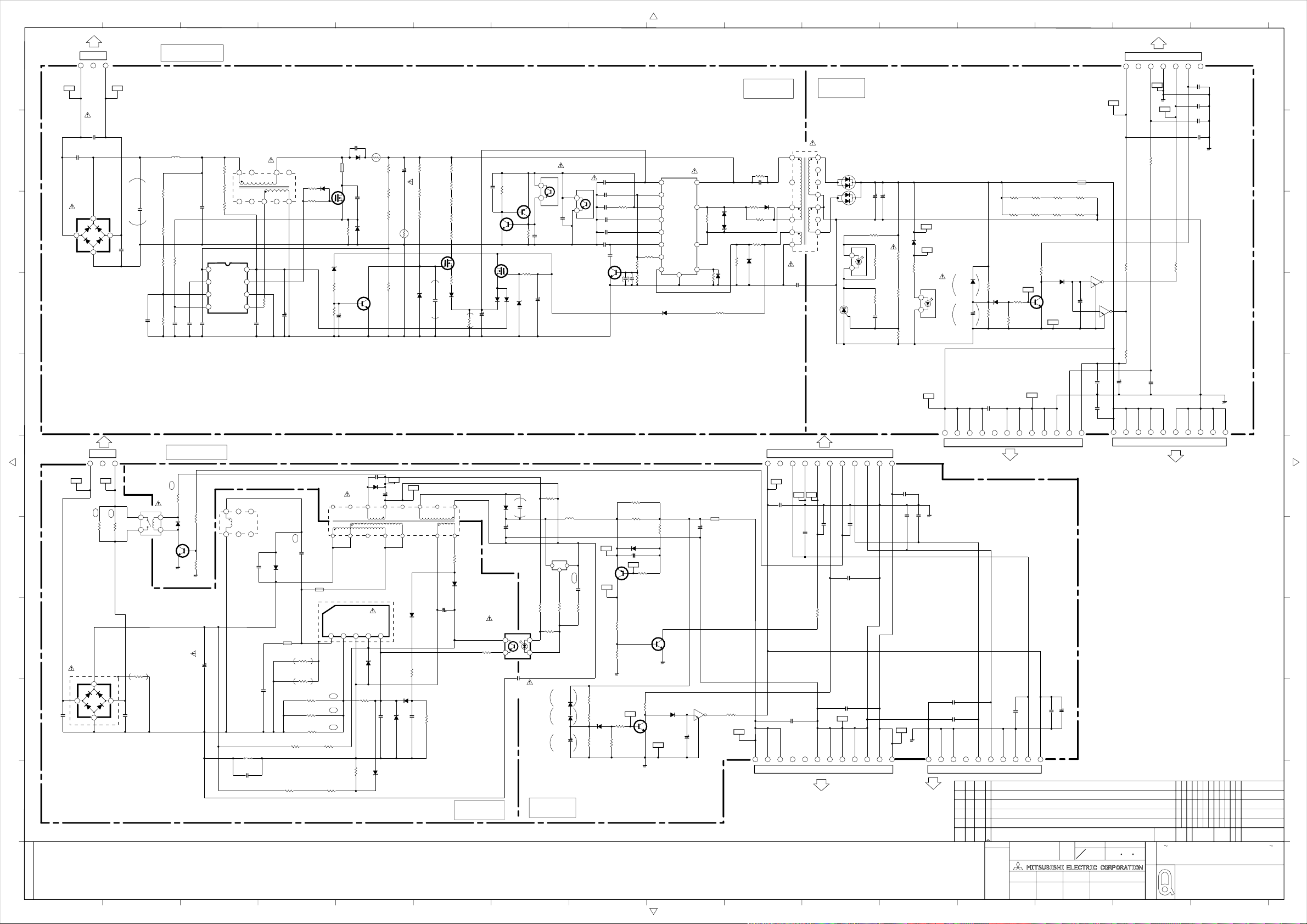
PWB-POWER
21 345678910111213141516
PWB-POWER
PB
V
a
AC2
C978
250V
b
M-1500
E
RBV-406H
c
4
123
NL
C977
250V
M-1500
E
D901
3
+
〜
〜
1
AC1
2
C979
250V
M-1500
E
d
0.56uDC450V
C901
C903
K-2200P
32INCH
L901
SN10P-601JB
F-470K
1/4W
R900
R901
F-470K
1/4W
1001/10W
R902
R904
F-330K
1/4W
F-10K
1/10W
R903
K-1000
C904
C902
1.0u
DC450V
0.82
C906
C907
R906
R907
R908
1234
K-2200
33K
1/2W
33K
1/2W
33K
1/2W
IC901
FA5500AN
L902
44H-5002
2
1
9
10
5678
C908
1234567
PC
R966
1/16W
47
R967
1/16W
GND
GND4
BRIGHT
SHORT1
47
R965
1/16W
47
47
BLON
BLON
R968
1/16W
T901
ETS28LZ145AD
1
2
3
4
5
6
COLD
13
12
YG805C06R
11
10
9
8
7
D920
1
2
1
2
D921
YG805C06R
PC902
KIA431A
-AT
3
3
21
IC910
35V
680u
C930
R950
PC123FY
/TLP421F
10K1/10W
R951
R952
C932
1/10W
1/10W
K-0.1
L910
FBR07HA850
R960
R959
R958
R957
1/2W
1/2W
120
R961
1/10W
3.9K
D930
UDZS_13B
R962
1/16W
F-22K
1/2W
120
120
R9Z5
1/16W
2.2K
R963
1/16W
68K
R9Z2R9Z1 R9Z4R9Z3
1/2W
120
R964
1/10W
10K
Q910B
35V
680u
C931
D922K
D922
UDZS_30B
D922A
F-27K
R953
1/10W
10K
68K
R955
R954
1/10W
1/10W
F-6.8K
F-3.9K
4.7K
R956
1/10W
PC901
PC123FY
/TLP421F
21
D923
1SS355
C933
-TE17
22u
1/2W
120
1/2W
120
D931
1SS355TE
-TE17
Q910
2SC3052-E,F
Q910E
1/2W
1/2W
120
120
Q911
DTC124EK
/UN2212
4.7u
C934
Q912
DTC124EK
/UN2212
LIVE
C911
1KV
470P
TH901
NTPDD120LD7B0
D903
R947
R946
3
R912
2W
0.1
D905
UDZS_18B
47K
1/10W
2SC3052-E,F
4.7K
1/10W
Q901
2SK3687
2
1
Q902
50V
10u
105C
D902
YG972S6R
ERA83
-004
C910
1KV
100P
D904
R916
1/10W
F-16K
R913
R914
R915
1/4W
1/4W
1/4W
820K
820K
820K
150u
450V
R917
C912
R918
R919
NTPDD120LD7B0
TH902
D906
UDZS_24B
1/4W
1/4W
1/4W
C913
R920
1/2W
15K
820K
R921
1/2W
15K
K-0.01
C927
R922
820K
820K
3
0
1/2W
R928
0.1
D907
SC802-04
R929
1/10W
10K
R923
R924
2
1
1/2W
15K
1/2W
15K
1/2W
15K
Q903
2SK2071
2SA1235A-E,F
Q905
2SC3052-E,F
2
1
D908
SD883-04
C914C981
35V
220u
R935
3
1/10W
Q906
1.5K
Q904
2SK2018
D909
SD883-04
R936
R930
1/10W
100K
1.5K
1/10W
D910
UDZS_18B
PC901
PC123FY
/TLP421F
34
C925
K-0.01
100u50V
C915
C926
1000
PC902
PC123FY
/TLP421F
34
2SC3052-E,F
C922
B50V
K-4700
Q907
C916
K-0.1
C917
K-0.1
C918
K-0.1
C919
K-0.047
C920
0.82
C921
330P CH
C924
B6.3V
4.7u
R931
1/10W
IC902
F9222L
D2
Vcc
7
Vref
R932
1/10W
R933
1/10W
33K
R934
1/10W
22K
10111213141516
comp
CS
CB
CON
1K
STB
VW
D911
AG01Z
10K
C923
B6.3V
K-4.7u
D912
PTZTE-2527B
G2
R940
1/10W
D913
PTZTE-2527B
D1.S2
19 20 23
3W
0.39
R944
ST
4
GND
8
R937
1/4W
2.2
22K
D914
ERA83-004
1/4W
18
R943
R939
100K1/10W
R938
C928
800V
H-0.022
R941
R942
D915
UDZS_5.6B
1M1/2W
D916
SD883-04
2701/2W
3.3K1/10W
C929
AC250V
M-1500
E
L903
FBR07HA850
4
56
R910
1/10W
33
SC802-09
7
8
47K1/10W
R909
0.1
C909
R911
1/10W
150
105C
100u
50V
SHORT1
E
C940
24V
0.01
C941
0.01
C942
CH100
C943
0.01
a
b
c
d
0.01
BRIGHT
BLON
S
10u50V
105C
C980
MATERIAL
SCALE
DIM
IN
mm
設計 検認
DESIGNED
C944
C949
0.01
NTS
e
PWB-POWER
PB
V
123
f
NL
AC2
CE
R972
10W
AC1
K910
LKS1AF-12V
CE
R973
10W
6.8
6.8
g
h
D940
D6SB80
3
+
4
〜
i
C950
M-2200EAC250V
1
R9Z6
180K
1/4W
2
〜
C951
j
34
2SC3052-E,F
M-2200EAC250V
37INCH
MB
120
2W
R999
12
Q922
SC802-04
D956
C952
200V
R948
R949
105C
1000u
4.7K
4.7K
1/10W
1/10W
24
578
L921
4700u
44A-0508C
C958
F910
1A
C976
1
1000
R1KV
C954
1000500V
D941
L923
BLO2RN1-R65
3300
630V
RG10A
BP
0.018
630V
C953
L922
BL02RN1-R65
R9Z7
390K
1/4W
R9Z8
390K
1/4W
R974
.22 2W
R975
.22 2W
R976
.27 2W
R977 R978
27K1/2W 27K1/2W
R979
1/2W
82K
C962
1000
D951
A001A
T910
44H-4004B
1 75
D S GND VIN
12345
MB
14
2
38
IC920
STR-G9628
FB/
OCP
D942
RD30ESAB4
R982
680
1/4W
MB
CH470
R980
1/2W
82K
MB
R981
C957
10K 1/16W
15V
C963
13
4
D944
RD12ESAB3
D947
RD6.8ESAB3
GND2
105C
220u
25V
1216 10
D945
AGO1Z
R984
1.8K 1/2W
D943
AGO1Z
CH1000
C956
15V
R986
680 1/2W
10K 1/16W
C955
35V
100u
105C
R985
D946
33
AGO1Z
1/2W
9
D950
FMX-G16S
C959
160V
105C
470u
C964
1000
R1KV
IC930
SE120N
123
L930
68u
MMF
.15
C961
1K 1/10W
1K 1/10W
R987
R988
D952
D953
C946
R989
1.8K
1/10W
1N4005E
-6580
1N4005E
-6580
10u
105C
R990
1K1/10W
R962
R970
F-22K
33K 1/2W
1/16W
R971
33K
1/2W
D930
UDZS_13B
R997
5.6K
1/16W
PC910
PC123FY
/TLP421F
34
C960
AC250V
M-2200
E
12
1115
R983
Q921E
Q921C
R963
68K 1/16W
D954
1N4005E-6580
Q921
2SA1320
/2SA1321
56K
R995R996
1/2W
1.2K
1/16W
R9Z5
1/16W
10K
R991
0.68 2W
R992
0.68 2W
Q921B
2SC3052-E,F
Q910B
C965
100u
10V
105C
Q920
R964
10K 1/10W
Q910
2SC3052-E,F
R993
10K
1/16W
R994
100 1/16W
D931
ISS355TE
-TE17
Q910E
120V
BL02RN1-R65
Q911
DTC124EK
/UN2212
4.7u
105C
C947
160V
105C
C966
330u
L931
R967
47 1/16W
1234567891011
BLON
BLON
120V
120V
120V
123456789101112
0.01
C943
120V
C967
BRIGHT
GND3
1000500V
NC
C942
GND
CH100
NC
LCD PANEL
LIVE
COLD
SHORT1
R965
SHORT1
C941
47 1/16W
GND
0.01
CN1
PC
24V
0.01
GND
PWB-POWER
IG
RELAY
0.01
C975
C940
C968
0.01
GND1
GND
GND
18V
GND
SYN
18V
GND
18V
0.01
E
C972
S
C973
18V
0.01
24V
24V
123456789101112
C948
0.01
LCD PANEL
C974
0.01
C971
0.01
C970
0.01
NC
IG
GND
GND
GND
12345678910
SYN
CN2
LCD PANEL
2
1 LT-3280D
32 33 34 35
標
改番
マ
副番 品番
CHANGE
|
SUB
ク
ITEM
MARK
ITEM
*
出図先 尺度
CHANGE
改定
GND
CN2
CH100
C945
SEL
E_PWM
LT-3780D
第3角法
作成 照査
DRAWN CHECKED
CAD
GND5
SEL
0.01
C944
BLON
BRIGHT
S
規格
3RD ANGLE
PROJECTION
本間 栗秋 石畑
21 345678910111213141516
10u50V
CH100
C945
105C
C980
24V
12345678910
GND
CN1
LCD PANEL
69 70 71 7972 73 74 75 76 77 78 80
C
O
(MI)
UNIT
C
AND DIMENSIONS
作成日付
2005 7 11
DATE
図
名
O
CODE
MARK
M
5
POWER-SUB
SCHEMATIC-DIAGRAM
REVISION NO.
TITLE OF DRAWING
25 26 27 28 29 30 31
APPROVED
880A647
e
S
f
g
h
i
j
改
摘
REMARK
要
24
理同期
**
APP. FROM
(12/14)
SCL=1/1
Page 59

2345678910111
IR
R0H2
2.7K
1/16W
R0H3
1/10W
47
R0H4
1/16W
100
L0G0
BLM21P221SG
L0G1
BLK1608HM121
C0G8
100 39
C0G9
STB_RMC
S5V
123
MB2
GND
S3B-PH-K-S
a
C0G0
D0G0
SFH235FA
b
D0G1
1SS355
R0G1
47K
1/16W
R0G0
12K
1/16W
10U
10V
C0G1
K-.01
R0G4
12K
1/16W
R0G2
12K
1/16W
C0G2
16V
47u
R0G3
1/16W
220K
R0G5
1/10W
270
C0G3
220
50V
R0G6
1/16W
10K
R0G7
150
1/16W
C0G4
K-.1
16V
IC0G0
OPA2350EA
1234
R0G8
1/16W
1.2K
5678
C0G5 C0G6
K-.1
16V
R0G9
220K
1/16W
R0H0
10K
1/16W
1U
25V
R0H1
1/16W
4.7K
C0G7
10U
10V
Q0G0
C3052
c
SERVICE
12345678910
MS1
FWE
SCK1
MD2
RXD1
TXD1
12345678910111213
14 1516 17 1819 20 2122 23 2425
1234567
MD1
MD0
RES
GND
VCC
S3.3V
MS2
SDA
SE
JBS-25P-3A3F90
S7B-PH-SM4-TBSM10B-SRSS-TB
SCL
GND
GEN_W
a
b
S5V
RESERVED
c
CONTROLLED
BLUE
123456
C0A4
AMBER
S5V
GND
LCD_RMC
39
S6B-PH-K-S
MB1
R0E0
KSHS612BT
FORMAT
F-56K
GND
R0E2
KSHS612BT
SW0E5 SW0E8SW0E7SW0E6SW0E4SW0E0 SW0E3
KSHS612BT
CH-UP CH-DOWNVOL-UP VOL-DOWN
R0E4
R0E5
F-3.3KF-12K F-2.2K
KSHS612BTKSHS612BT
R0E6R0E3
F-1.5KF-5.6K
KSHS612BT
KSHS612BT
DEVICE POWER
C0E1C0E0
C0E2
100
100
100
L0A1
BLM21P221SG
D0A2
Q0A2
A1235A
R0A7
2.7K
1/10W
R0A3
2.2K
1/16W
R0A4
6.8K
1/16W
R0A9
47
1/10W
C0A8 C0A7
16V4716V
K-.1
D0A3
UDZS9.1B
IC0A1
GP1UM283RK
C0A6
K-.01
C0A3 C0A2 C0A1
100 100 100
R0C1
10K
L0A2
C0A5
39
CH
BLM1608HM121
132
R0A5
1K
1/10W
D0A1
BLUE
Q0A1
A1235A
R0A2
2.2K
1/16W
SLI-343DC
ORANGE
d
R0A1
6.8K
1/16W
e
SLR343BBT
C0E3
100
RESERVED
PWR_SW
KEY0
KEY1
GND
5
MC
S5B-PH-K-S
1234
d
e
f
g
CHANGE
改定
CONNECT
SP_R_P
SP_R_N
SP_L_P
SP_L_N
1234
B4B-XH
MA
PX
B2B-XH-AM
12
5V
1234
B4B-PH-K-S
SP_R_P
SP_R_N
SP
SP_L_N
SP_L_P
J0K1
JBY-25P-1A3A90
14 15 16 17 18 19 20 21 22 23 24 2526
12345678910111213
GND
R0J1
D0J1 R0J3
220K
1SS355
TE17
R0J2
100
220K
R0J4
100
D0J2 C0J1 C0J2
1SS365
16V
100
TE17
105C
K-.01
IC0J1
TC74HCU04AF
Vcc
1
2
3
4
5
R0J5
6
100
GND
7
Q0K1
DTC124EK
R0K1
/UN2212
100
R0K2
Q0K2
DTC124EK
/UN2212
14
R0J6
100
13
12
R0K5
100
11
10
9
8
33K
R0K4
33K
R0K3
100
C0J4 C0J3
K-.0471050V
12345678
910111213141516
1718192021222324
C3C4
C1C2
30
12345
11 12 13 14 15
678910
16
EDID
J0K2
QH11121-EBO
J0K3
KES-15S-2A3A14
改番
CHANGE
MARK
2
1
32 33 34 35
副番 品番
SUB
ITEM
ITEM
LT-3780D
LT-3280D
標
マ
|
ク
*
出図先 尺度 作成日付
規格
第3角法
CAD
3RD ANGLE
PROJECTION
作成 照査 設計 検認
DRAWN CHECKED DESIGNED
本間 栗秋 石畑
DIM
MATERIAL
SCALE
IN
mm
NTS
AND DIMENSIONS
2005 7 11
APPROVED
69 70 71 7972 73 74 75 76 77 78 80
C
O
UNIT
C
O
CODE
M
REVISION NO.
TITLE OF DRAWING
APP. FROM
DATE
(MI)
MARK
5
図
CONTROL IR LED
名
SCHEMATIC-DIAGRAM
25 26 27 28 29 30 31
880A647
改
理同期
**
摘要
REMARK
(13/14)
f
g
24
2345678910111
SCL=1/1
Page 60
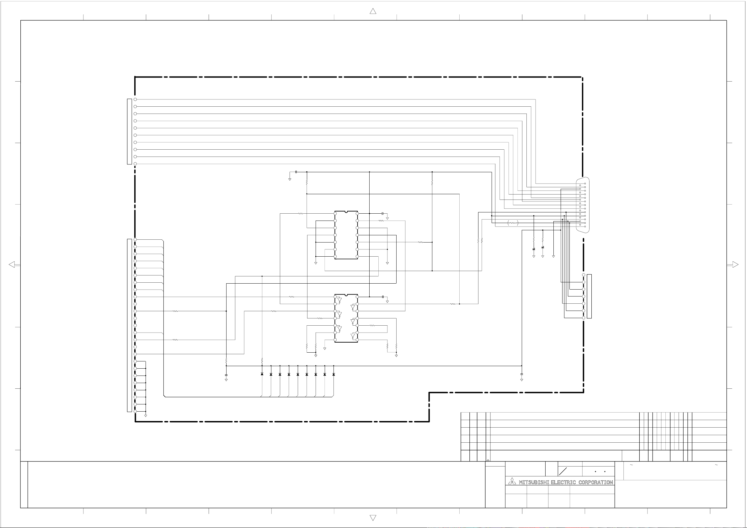
2345678910111
a
RXD1
12345678910
a
TXD1
b
SCK1
b
FWE
SM10B-SRSS-TB
MD2
MD1
MD0
RES
INPUT1
GND
VCC
C001
1SS355TE17
D003
K-.01
R007
2.2K
IC001
R006
100
R020
100
R022
R021
10K
10K
1SS355TE17
1SS355TE17
1SS355TE17
D004
D005
DAT1
DAT2
1SS355TE17
D006
D007
DAT3
DAT4
DAT5
HD74LV125A
1
DEO
2
AO
3
DO
4
OE1
5
A1
6
O1
78
IC002
74LCX04MTCX_NL
1
2
3
R023
100
4
5
6
78
1SS355TE17
1SS355TE17
D009
D008
FEED
DAT6
C002
14
13
OE2
12
A2
11
O2
10
OE3
9
A3
O3
14
13
12
11
10
9
K-.01
R008
100
C006
K-.01
R024
100
R026
R025
10K
10K
R009
2.2K
SDA
S3.3V
R014
100
R013
R028
100
R027
100
R012
100
100
SCL
GEN_W
S5V
R005R004
1010
C004
16V
C003
10u
16V
10u
C007
K-.01
GEN_W
S3.3V
12345678910111213
141516171819202122232425
SE
JBY-25P-1A3A90
S7B-PH-K-S
7
S5V
6
5
GND
4
MS2
SCL
3
SDA
2
1
c
d
e
f
1
2
3
4
5
6
7
JBY-25S-1A3A90
8
9
10
11
12
13
INPUT2
DSub25
14
15
16
17
18
19
20
21
22
23
24
25
STB
DAT0
DAT1
DAT2
DAT3
DAT4
DAT5
DAT6
1SS355TE17
D001
R019
100
R018
10K
1SS355TE17
D002
STB
DAT0
R015
100
FEED
R016
100
R017
10K
C005
K-.01
g
c
d
e
f
g
CHANGE
改定
2
LT-3780D
1
改番
CHANGE
MARK
32 33 34 35
副番 品番
SUB
ITEM
ITEM
LT-3280D
標
マ
|
ク
*
出図先 尺度 作成日付
規格
第3角法
CAD
3RD ANGLE
PROJECTION
作成 照査 設計 検認
DRAWN CHECKED DESIGNED
本間 栗秋 石畑
DIM
MATERIAL
SCALE
IN
mm
NTS
AND DIMENSIONS
2005 7 11
APPROVED
DATE
図
名
69 70 71 7972 73 74 75 76 77 78 80
C
(MI)
MARK
5
JIG
O
UNIT
C
O
CODE
M
REVISION NO.
TITLE OF DRAWING
SCHEMATIC-DIAGRAM
APP. FROM
改
理同期
**
摘要
REMARK
(14/14)
25 26 27 28 29 30 31
880A647
24
2345678910111
SCL=1/1
 Loading...