

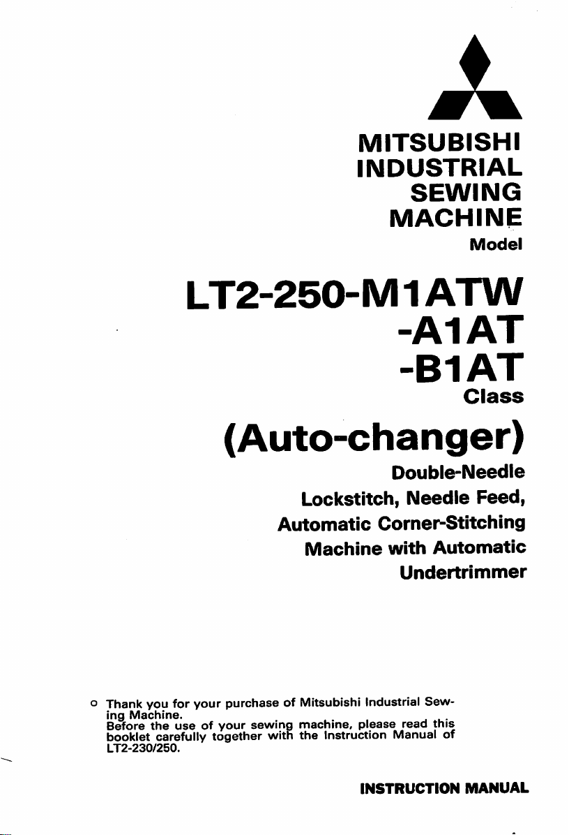
MITSUBISHI
INDUSTRIAL
SEWING
MACHINE
LT2-250-M1ATW
-A1AT
-B1AT
(Auto-changer)
Double-Needle
Model
Class
o Thank you for
ing
Machine.
Before
booklet carefully together with
LT2-230/250.
the
your
purchase
useofyour
Lockstitch,
Automatic
Machine
of Mitsubishi Industrial
sewing
machine,
the
Instruction Manual of
Needle
Corner^Stitchlng
with
please
INSTRUCTION
Automatic
Undertrlmmer
Sew
, . .
read
this
Feed,
MANUAL
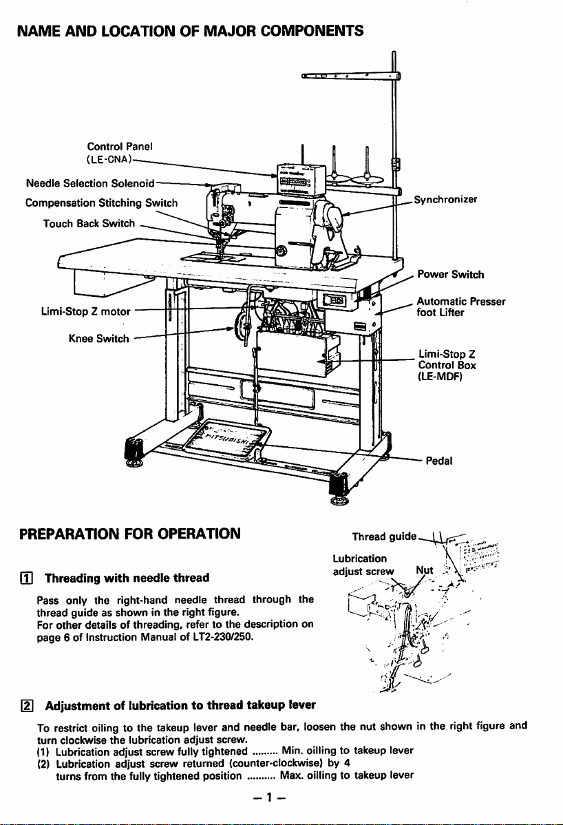
NAME
Needle
AND
Selection
Compensation
Touch
LOCATION
Control
(LE-CNA)
Solenoid
Stitching Switch
Back
Switch
Panel
OF
MAJOR
COMPONENTS
Synchronizer
Power
Switch
Limi-StopZmotor
Knee
PREPARATION
Switch
—
FOR
OPERATION
Q] Threading with needie thread
Pass only the right-hand needle thread through the
thread
guide as
other
For
page
6 of Instruction Manual of LT2-230/250.
showninthe
right figure.
details of threading, refer to the description on
Thread
Lubrication
adjust
screw
guide
Automatic
foot
Lifter
Limi-Stop Z
Control
Box
(LE-MDF)
Pedal
Presser
,
Adjustment of lubricationtothread
To
restrict
oiling
to the
takeup
turn
clockwise
the
lubrication
leverand needle bar,
adjust
screw.
takeup
lever
loosen
the nut shown in the right
(1) Lubrication adjust screw fullytightened Min.oillingto takeup lever
(2) Lubrication adjust
turns
from
screw
the
fully tightened position Max. oilling to takeup lever
returned (counter-clockwise) by 4
-1
-
figure
and
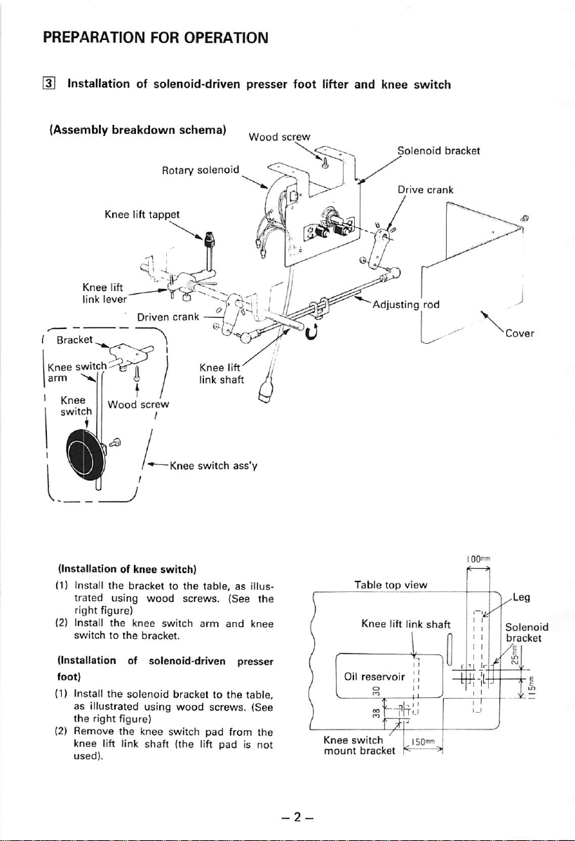
PREPARATION
FOR
OPERATION
Installationofsolenoid-driven
(Assembly
Knee
Iarm
Knee
link
switch
>*^1
breakdown
Knee
lift
lift
lever*
(
Wood
tappet
Driven
screw
schema)
Rotary
crank
-Knee
solenoid
""^7r-i '
/
Knee
lift
link
shaft
switch
presser
ass'y
Wood
screw
foot
lifter
and
knee
Solenoid
Drive
Adjusting
switch
bracket
crank
rod
(Installationofknee
(1) Install
(2)
the
trated
using
right
figure)
Install
the
switchtothe
switch)
brackettothe
wood
screws.
knee
switch
bracket.
table,asillus
(See
arm
and
knee
the
(Installation of solenoid-driven presser
foot)
(1) Install
(2)
the
solenoid
as illustrated using
the
right
Remove
knee
used).
figure)
the
lift link
knee
shaft
bracket to
wood
switch
(the
lift
the
table,
screws. (See
pad
from
padisnot
the
Knee
mount
Oil
Table
Knee
reservoir
switch
bracket
top
view
lift
link
shaft
—'•
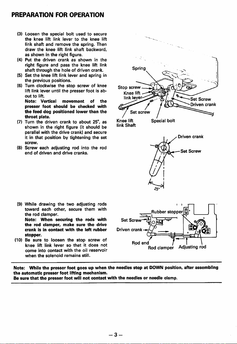
PREPARATION
FOR
OPERATION
(3) Loosen
the
knee
link
shaft
dravr
as
showninthe
(4)
Put
the
right figure
shaft
(5)
Set
the
the
previous
(6)
Turn
lift link
outtolift.
Note;
presser
the
feed
throat
(7)
Turn
showninthe
parallel
it in
that
screw.
(8)
Screw
endofdriven
the
special bolt
lift
link
levertothe
and
knee
remove
lift
link
the
right figure.
driven
crankasshowninthe
and
through
knee
pass
the
holeofdriven
lift link
positions.
clockwise
lever
Vertical
foot
dog
the
until
the
movement
should
positioned
stop
plate.
the
driven
cranktoabout
right
the
figure
drive
with
positionbytightening
each
adjusting
and
drive
usedtosecure
the
spring.
shaft
the
knee
lever
and
screwofknee
presser
footisab
be
checked
lower
(it
should
crank)
and
rod
into
cranks.
knee
Then
backward,
lift link
crank.
spring
of
with
than
25°,
secure
the
the
the
the
set
rod
lift
be
Spring
in
Stop
screw
Knee
lift
link
lever-
screw
Knee
link
lift
Shaft
as
Special
bolt
Driven
Set
Set
Driven
crank
Screw
Screw
crank
(9) While
toward
the
rod
Note:
the
rod
crankisin
stopper.
(10) Be
suretoloosen
knee
come
when
Note: While
the
automatic
Be
sure
that
drawing
each
the
other,
clamper.
When
securing
clamper,
contact
lift
link
leversothatitdoes
into
contact
the
solenoid
the
presser
presser
the
presser
two
make
with
the
with
remains
foot
foot
foot
adjusting
secure
them
the
sure
the
stop
the
oil
still.
goesupwhen
lifting
mechanism.
will
not
rods
the
left
screw
reservoir
contact
rods
with
with
drive
rubber
not
Rubber
stopper
Set
Screw-^c
Driven
crank-»v
of
the
with
-3-
Rod
end
needles
stopatDOWN position,
the
needles
or needle clamp.
Rod
clamper
Adjusting
after
rod
assembling

PREPARATION
FOR
OPERATION
IS Installation of control panel
(1) Install
(2)
(3)
the
machine
control
head,
figure.
(To install,
control
to
slightly
en
Plug
into
videdinthe
Bind
panelonthe
screws.)
the
the
all
cords
while
compress
needle
correspoinding
control
with
der,asshowninthe
panel
as
shown
lightly
holding
topofmachine
the
rubber
selection
panel.
the
furnished
right
figure.
on
the
in
the
down
pads,
solenoid
receptacle
cord
top
right
head
tight
cord
pro
hol
the
Rubber
pad
of
Cord
holder
Plug (for
selection
Screw
needle
solenoid)
I External wiring
Connect
pensation
trol
right
(1)
(2)
(H Setting of
Set
the
figure.
the
automatic
stitch
paneltothe
switch,
control
figure.
The
compensation
shouldbeconnectedto2-pin
nector.
The
knee
pin
Note:
be
for
switch
white
connector.
Before
suretoturn
safety.
pluggingorunplugging,
DIP
box
the
DIP
switches
control
boxto
"ON",asshown
presser
foot
lifter,
knee
switch
and
com
con
box,asshowninthe
stitching
shouldbeconnectedto2-
off
the
power
switch
black
switch
cable
con
switches in the control
S4L,
S2,
CKD
and
64P
inthe
right
Compensation
switch
Knee
switch
(LE-FM-CFT) •
Synchronizer ^ panel Sewingmachine
0} u
Clutch
n° §
iL
<A
Brake
External
volume
in
|
ON
la
SWI
_i
-j
tn
W
(n
PSU PSD
DELAY
M H
SPEED
^ ^
select
^ H
Control
stitching
^
Control
switch
i
ON
a Q a •
SW3
ON
BSBsasog
SW4
w
ON
HBEraangg
SW5
tEnjW
o — uJ +
panel
Automatic
Presser
(h
(55
o <
CNA)
(LE-
foot
II
— W (/) (D
CO
? 3 •-
—
_i_ia:
tOltO)
lifter
-4-

OPERATION
[T]
Setting of switches and counters on
FOR
AUTOMATIC
AUTO
fOMH
STAIR
tm
CORNER
the
control panel
STITCHING
3333KI23
23
3
232
Tl
(1)
Set the start
backward stitch "B" on
(2) Set the end backtacking "END" switch (2) to "ON" and
backward stitch "D" on
(3) Set the
Note:
(4)
Set
the
counter
o
The
When
(5) Set
number
Note:
single-needle
starts
backtacking
"CORNER
When
"NUMBER"
®-
numberofthe
all
When
without
SEWING"switch ® to "ON".
this
switchis"OFF",
(numberofcorner
preset
steps
of stitches to be
numberofsingle-needle
one
stitch and, after
signle-needle
"START"
counter®.
counter
next
corner
are
stitching.
switch(J)to "ON" and set number of
($).
usual
doudle-needle
stitching
completed,
completed
the
stitching
with single-needle stitching in
stitchesissetto"0",
(See
steps)
stepsisdisplayed
the
counterisreset
fabric is turned, double-needle stitching immediately
the
right
figure)
forward
set
number of forward stitch "C" and
stitchingispossible.
withinarange
by LED.
t0""1".
deep
from1step
each
pedal
heeling
steponcounter
stitch "A" and
to 8
steps
on
down
causes
Set
the
(6)
directionofturnateach
LEFT/RIGHT SELECTOR
The
directionofturnisdisplayed
switch.
For leftwardturn ( _11 i , set switch
For
rightward
—
turn(11—
endofcorner
(Maximum
i , set
by LED
switch
eight
colour
_Mi_
_HL
stitching
turns
•••
step
may
red
green
Single-needle
stitching
LED will light.
LED will light.
/ /
/ /
on
be
/ /
Double-needle
Stitchino

OPERATION
(D
Retracing
Every one depression of
are
retraced,besuretocheck
[3]
Continuous single-needle stitching
(1)
Set the
FOR
AUTOMATIC
of comer stitching step
the
"SUB" switch causes retracing of one corner stitching step. When steps
the
"SINGLE
NEEDLE"
switch ® to
CORNER
position by LED.
"ON".
STITCHING
(2) To'select the left needle or the right needle, set switch (]j).
*To
stop
the
•To
stop the right needle, depress
left needle,
depress
switch-BK.
switch_^L
red LED will flicker.
green
(3) Toe down the pedal to start continuous single-needle stitching.
(4)
Todisengage continuous single-needle
pedal.
[4]
Compensation stitching
Compensation stitching is
corner
stitching, or
corner
stitching.
(1) By
once
depressing
switch,
one
forward
stitch
direction.
(2) By depressing
switch while holding
switch,
one
backward
stitch
direction.
made
when
one
the
compensation stitch
can
the
compensation stitch
down
can
before starting
stitch is
be
added
the
be
added
stitching,
added
in
the
touchback
in
the
set the
in
LED
switch
will
@ to
flicker.
"OFF"
and toe downthe
Compensation
stitching
Touchback
switch
switch
Example of
Stitching
NUMBERofcorner
ing
Step
Numberofcorner
needle
Comer
pattern
steps
stitches
stitching direction
corner
stitch
single-
stitching
Needle
(6.4mm)
Stitch
(D (2)
LEFT
patterns
gauge
length:
LEFT
1/4"
3.2mm
LEFT
-6-
LEFT
®;'''
Needle
Stitch length:
RIGHT
LEFT
gauge
1/4" (6.4mm)
3.2mm
LEFT
RIGHT
LEFT

OPERATION FOR AUTOMATIC CORNER STITCHING
(D Stitching procedure
(Standard specification Pedal is deeply
heeled down for corner stitching.)
(1) Shallowly
presser
(2) Put fabrics in position.
(3) For start bacldacking and double-needle
stitching,
(4) Corner stitching is accomplished in
order
repeated for
toe
foot.
toe
(2)*~(§)
down the pedal to lift
down
the
pedal.
shown
below
the
preset
(stitching
number
the
the
is
of steps).
Note: When
is
completed,
(5)
When
backtacking is
trimmed.
the
the
knee switch is
present
the
numnberofsteps
counterisresetto"1".
set
done
and
the
(6) When the knee switch is held at "ON",
presser
foot
goes
(7)
Operation
Stitching
Pedal
opera
tion
Stitching
tern
Remove
pat
the
0
Start
tacking
ble
reedle
stitching
Pedal
fabrics.
back
and
toe
dou
down
up.
Single-
needle
with
fixed
berofstitches-*
Presser
goes
up.
Pedal
deeply
heel
down
stitching
foot
to "ON",
threads are
turned-♦Press
num
er foot
down.
Continued
—
Neutral
end
the
Fabrics
goes
(1)
Neutral
(2)Shallow toe down (inching)
(3) Deep
toe
down
(4)Shallow heeldown (presser footgoes
up)
(5)Deep heel down (corner stitching)
are
-
Note: For
ing force, refertothe
page22of
LT2-230/250.
Single-
needle
stitching
with
fixed
berofstitches
adjustmentofthe
the
(§)
needlestitching
num
Pedal
toe
down
description on
Instruction
Oouble-
pedal
Manual
(§)
End
ing
and
trimming
Knee
-ON-
of
backtack
thread
switch
Note:
Do
not
If
the
toeing
turn
poweristurned
down
the
stitching as in (U on
off
the
off
pedal. If
the
power
during
corner
during
corner
the
powerisinterrupted
stitching,
stitching.
double-needle
by mistake,
stitching
start
may
and
notberesumed
continue
previous page described to resume double-needle stitching.
-7-
single-needle
by

AUTOMATIC CORNER STITCHING .... SPECIAL OPERATION PROCEDURE
*Besides the previously described standard operation procedure, automatic corner stitching may be
madeinthe
[T]
Cornerstitching... Knee switchoperation
(1) For
foot
switch
showninthe
Set
(2)
in
(3) For
^
Stitch
tacking
ing
double
stitching
Pedal
Pedal
down
opera
tion
Stitch
ing
pat
tern
following
this
operation,
lifter,
compensation
and
control
the
DIP
"64P"inthe
the
corner
switches
control
right figure.
stitching, perform
operationinthe
Corner
stitching Knee
Thread
trimming
Presser
lifter UP
Start
back-
(^Single-
and
needle
ing with fixed
needle
number
stitches-.
Presser
goes
up.
toe
Knee
ON
—
way:
the
automatic
stitch switch,
panel
right
shouldbewires
figure.
"S4L",
boxto"ON"asshown
following
tion
...
Deep
down
Shallow
ing
stitch
foot
switch
Fabrics
turned-.
Presser
foot
goes
of
down.
Continued
Neutral
the
order:
switch
pedal
down
are
-
presser
"CKD"
following
opera
heeling
pedal
(^Single-
needle
ing with fixed
numt>er
stitches
knee
heel
stitch
of
Pedal
as
and
toe
switch-^
(^Double-
needle
stitching
down
i
(^
tacking
thread
ming
Pedal
heel
End
deeply
down
back-
and
trim
Compensation
stitching switch
whittt
ON
QD
SWI
Automatic
foot
lifter
ON
SW3
Control
panel
presser
CM(O§
(OCOO S
oonn
05
CO(0to
Q.
m Corner stitching ... Shallow pedal heel
ing
operation
(1) The wiring
standard
(2)
The
"CKD"
be
setto"ON",asshowninthe
(3) Install
the
next figure. The foot switch is used to lift
the
does
corner
DIP
and
the
presser
not differ from
stitching.
switches
"64P"inthe
foot
"S4L",
switch
(option),asshown
control
foot in the middle of stitching.
"SSL",
box
right
that
"82",
should
figure.
for
in
-8-
nn
ON
SWI
ON
SW3
CMCO§
<0 O) o S
a 8
no
05
COyjM
CL

(4) For corner stitching, perform the following
operation in
the
following order:
Cornerstitching Shallow pedai heel
ing
Threadtrimming...
down
Knee
switch opera
tion
Presser foot
lifting
at start of stitching
Knee switch opera
tionorshallow
al
Presser
foot lifting in
heeling
the
middle of shal
low stitching
Foot
switch
operation
Stitch
^
Start
back
ing
Pedal
opera
tion
Stitch
ing
pat
tern
tawing
double
stitching
Pedal
down
toe
and
needle
(^Single-
needle
ing with fixed
number
stitches-*
Presser
goes
Pedal
heel
up.
shallow
down
stitch
foot
of
—
(^Fabrics
turned-*
Presser
foot
goes
down.
Continued
Neutral
ere
-*
(^Single-
needle
ing with fixed
number
stitches
stitch
Pedal
of
ped
(^Double-
needle
stitching
toe
down
Foot
(g)
tacking
thread
ming
Knee
-ON-
End
switch
and
trim
switch
back-
Note: Foot switch
(LE-CFT-3)
is optionally available.
-9-

SPECIFICATIONS
*Sewing
machine
Model
Application
Max.
speed
spm
Stitch length mm (inch)
Presser
foot
thread
stroke
trimmer
system
Automatic/manual
Needle
Hook
(for
Bobbin
Lubrication
Compensation sewing
Touchback
Wiper
Needle
gaugemm(inch)
Note:
Forfeed dog, throat plate, slider plate, bobbin
Bobbin
•Applicable
Motor
Control
Equipment
box
•Auto-Changer
Model
Automatic
presser foot
lifter
Control
panel
Knee
switch
head
mm
(inch)
use)
should
be of
good
quality
CA-Z402E
Kit
LE-CNA-KM
(Standard)
LE-FM.2
(Electromagnetic type)
LE-FM-CFT
LE-MDF
LE-CNA
LT2-250-M1ATW
Light to
3,500
4 (5/32)
DP X 5
135
134Nm90
Horizontal
hook
with
(with
thread
vention
Standard-6.4
that
is not
CB-Z402E
LE-CNA-KA
(Option)
LE-FA
(Pneumatic
LT2-250-A1AT
medium-heavy
3,000
5 (3/16) 5 (3/16)
#14,
X 5
#14,
type
standard
bobbincase
slack
pre
spring)
Aluminum
Provided
(1/4),
case
and bobbin, use those for thread trimmer application.
deformed.
•Control
Medium-heavy
9/7
135
Horizontal
(with
bobbin
Automatic
Optional-3.2,
Panel
Model
3,000
(11/32/9/32)
DP X 5
#16,
X 5
#16,
134Nm100
type
for
Provided
Provided
large-sized
slack
thread
lubrication
thread
4.8, 8, 9.5, 12.7 (1/8, 3/16, 5/16,
Backtacking
Number
of
type)
corner-stitching
Number
comer
Process
Continuous
single-needle
stitching
of
stitches
return
steps
prevention
trimmer
Not
provided
4-dial
Possible
LT2-250-B1AT
Medium-heavy
3,000
(15/64)
6
DP X 5
135
134Nm110
hook
with
spring)
use
LE-CNA
system
(0 to 9 stitches),
start
and
Max.
0to9
stitches
Possible
for right
#18,
X 5
bobbincase
3«,
end
8
and
left
to
heavy
2,500
7 (9/32)
#18.
1/2)
needles
Amitsubishi
HEAD OFFICE
MITSUBISHI
OEMCI BLOG
electric
MARUNOUCHI
TOKYO
corporation
100
TELEX
J2A532
CABLE MELCO TOKYO
A180E066P01
 Loading...