

MITSUBISHI
INDUSTRIAL
LT2-230.-250
Lockstitch,
Undertrimmer,
Variable
A
SEWING
MACHINE
Model
Class
Double-Needle
Automatic
Speed
INSTRUCTION
MANUAL
-CONTENTS-
PREPARATION
m Power cable
m
Connectionofcontrol
FOR
OPERATION
connection
box
m Adjustment of needle bar stop position 2
CAUTIONS
ON
USE
m Oiling (1) 3
S Oiling (2) 3
[31 Oilingcondition 4
[4] Adjustment of oilingto rotating hook 4
Cautions on operation 4
OPERATION
Installation of needles 5
Winding
Selection of
of bobbin thread 5
thread
Threading of needle threads 6
Adjustment of stitch length and stitch reversing (touch-back) 7
Setting of bobbin 7
Threadingof bobbin threads 8
Tension adjustment of bobbin threads 8
Balance of
Needle
10
Adjustment of presser foot pressure 8
11
Timing between rotating hook motion and needle motion
12
Adjustment of feed dog height 11
13
Relationship between rotating hook motion and take-up lever motion 12
14
Relationship between hook motion and opener motion 12
15
Relationship between needle motion and feed dog motion 13,14
16
Needle bar (left or right) stop operation {LT2-250) 15
17
Relationshipbetweenangle of corner stitching and stitch length 15
18
Installation
19
Adjustment of thread trimmer cam 17
20
Adjustmentofthread
21
Adjustmentofmeshing
22
Sharpening of fixed knife 19
23
Adjustment for change of needle gage 20
24
Wiper
25.
ADJUSTMENT
thread
thread
tension
tension
of movable knife 16
tension
regulator
pressureofmovable
knife
and
fixed
knife
adjustment
AND
OPERATION
OF
CONTROL
UNIT
9,10
1
2
6
8
8
18
19
21
m "1-2 POSITION" select switch operations 22
m
Pedal
m
m
operation 22
Adjusting
Adjusting
the
the
pedaling
stitching
forces
speed
22
23
fSl Optional functions 24, 25
CAUTION
26,
27
PREPARATION
• Overall
viewofassembled
sewing
machine
FOR
Touch
OPERATION
Faceplate
back
switch
Phase
reversing
2-type
LIMI-STOP
Balance
\/
_
plug
X
motor
wheel
Synchronizer
Power
Operation
With
this
box,
additional
as
automatic
used.
pushbutton
box
(option)
optional
functions
tackstitch
operation
can
such
be
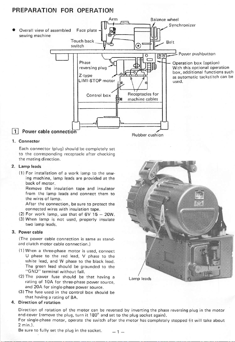
m Power cable connection
1.
Connector
Each
connector
to
the
corresponding
the
mating
(DFor
installation
backofmotor.
Remove
from
the
wiresoflamp.
After the connection, be sure to protect the
connected
(3) When lamp is
two
lamp
3.
Power
cable
(The
power
(l)Whenathree-phase
direction.
the
the
leads.
cable
(plug)
shouldbecompletely
receptacle
of a
work
lamptothe
insulation
lamp
leads
wires
with
not
connectionissameasstand-
tape
and
connect
insulation
used, properly insulate
motorisused,
Control
after
and
tape.
box
set
checking
sew-
insulator
them
connect
Receptacles
machine
Rubber
to
for
cables
cushion
„
rMft
,
Sln%f9h
<btV''
«, .•
jCA
"GND"
terminal
ratingoflOA
and
20A
(3)
The
fuse
that
4.
having a
Directionofrotation
Direction of
end cover (remove the plug,
For single-phase
2
min.).
without
for
for
usedinthe
rotationofthe
three-phase
single-phase
control
ratingof8A.
motor,
operate
fail.
power
power
motor
turn
source,
source.
box
should
can
be reversed by inverting
it 180° and set to the plug socket again).
the
switch after
Besure to fully set the plug in the socket. _ 1 _
j
Lamp
leads
^
be
the
phase
the
motor
has completely
reversing plug in
stopped
the
(it will take
motor
about
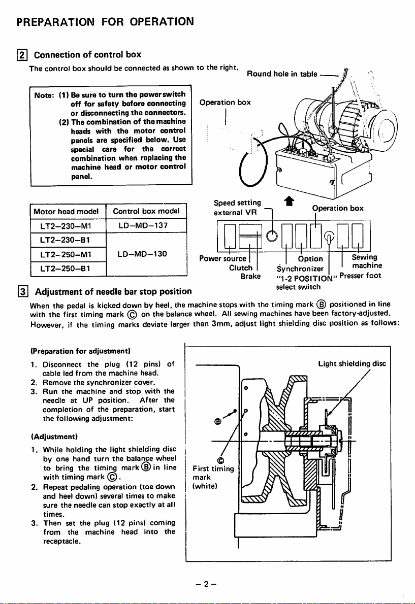
PREPARATION
[2I
Connection
The
control
box
Note:
(1) Be
off
or
disconnecting
(2)
The
heads
panels are specified below. Use
special
combination
machine
panel.
Motor
head
model
LT2-230-M1
LT2-230-B1
LT2-250-M1
LT2-250-B1
[3]
Adjustmentofneedle
When
the
with
However,
pedaliskicked
the
first
if the timing
timing
FOR
OPERATION
of controlbox
shouldbeconnectedasshowntothe
suretoturn
for
combinationofthe
with
the
safety
before
the
care
for
when
headormotor
Control
LD-MD-137
LD-MD-130
bar
downbyheel,
mark
@ onthe
marks
power
the
connectors.
motor
the
replacing
box
stop
deviate
switch
connecting
machine
control
correct
the
control
model
position
the
balance
larger
machine
wheel.
than 3mm, adjust light
right.
Operation
Speed
external
Power
stops
All
source
Clutch
Round
box
setting
VR
Brake
with
sewing
holeintable
Synchronizer
"1-2
select
the
timing
machines
shielding
Operation
Fh
9
Option
POSITION"
switch
mark
(§)
have
positionedinline
been
discposition as
box
Sewing
machine
Presser
foot
factory-adjusted.
follows:
(Preparation
1.
Disconnect
cable
2.
Remove
3.
Run
needleatUP
completionofthe
the
(Adjustment)
1. While holding
by
to
with
2.
Repeat
and
sure
times.
3.
Then
from
receptacle.
for
led
from
the
the
machine
following
one
hand
bring
the
timing
pedaling
heel
down)
the
needle
set
the
the
adjustment)
the
plug
the
machine
synchronizer
and
position.
preparation,
adjustment:
the
light shielding disc
turn
the
timing
mark
(§).
operation
several
can
stop
plug
(12 pins)
machine
(12
pins) of
head.
cover.
stop
with
After
balance
mark® in
(toe
timestomake
exactlyatall
coming
head
into
the
the
start
wheel
line
down
the
First
mark
(white)
-2-
timing
Light
shielding
disc
/
CAUTIONS
m
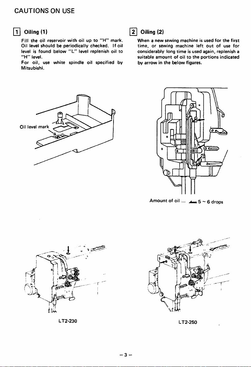
Oiling
Fill
the
Oil level
level is
"H"
level.
For
oil,
Mitsubishi.
Oil
level
ON
USE
(1)
oil
reservoir
shouldbeperiodically
found
use
mark
below
white
with
"L"
spindle
oilupto
checked.
level
replenish
oil
"H"
specified
mark.
If oil
oil
[2]
Oiling
(2)
Whenanew
to
by
time,orsewing
considerably
suitable
by
arrowinthe
sewing
machineisused
machine
long
amountofoiltothe
timeisused
below
figures.
left
again,
portions
for
the
outofuse
replenish
indicated
first
for
a
4
jIjL
:!
j '
LT2-230
Amountofoil
-3
-
..
LT2-250
5 ~ 6
drops
CAUTIONS
[y|
Oiling
ON
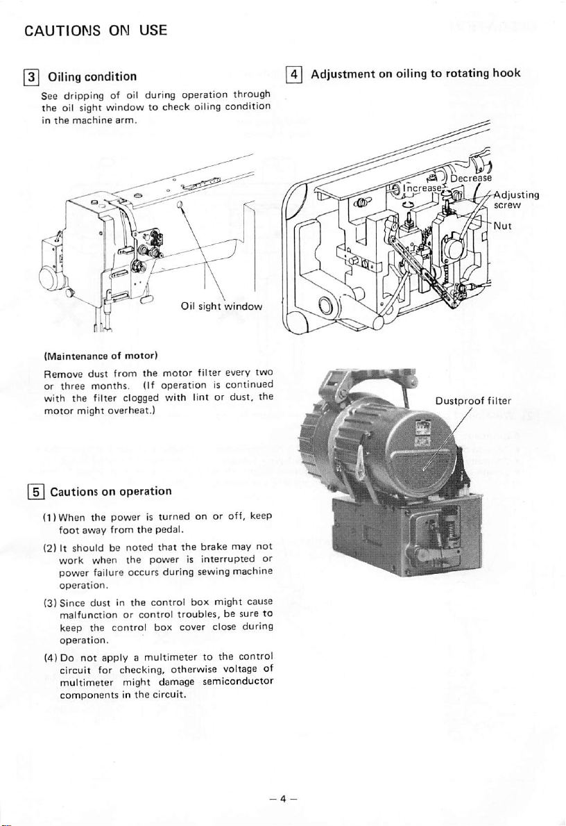
condition
USE
See dripping of oil during operation through
the oil sight window to check oiling condition
in
the
machine
(Maintenanceofmotor)
Remove
or
three
with
the
motor
dust
from
months.
filter clogged
might
overheat.)
arm.
Oil
sight
window
the
motor
(If
filter
operationiscontinued
with
lint or
every
dust,
two
the
Q
Adjustmentonoilingtorotating
Dustproof
hook
filter
Cautionsonoperation
(1)When
(2) It
the
foot
work
poweristurned
away
from
shouldbenoted
when
the
pedal.
that
the
the
powerisinterrupted
on or
brake
off,
power failure occurs during sewing machine
operation.
(3)
Since
malfunction
keep
operation.
(4) Do
dustinthe
the
not
applyamultimetertothe
or
control
control
control
box
box
might
troubles,besure
cover
close
circuit for checking, otherwise voltage of
multimeter
componentsinthe
might
damage
circuit.
semiconductor
may
during
control
keep
not
or
cause
to
OPERATION
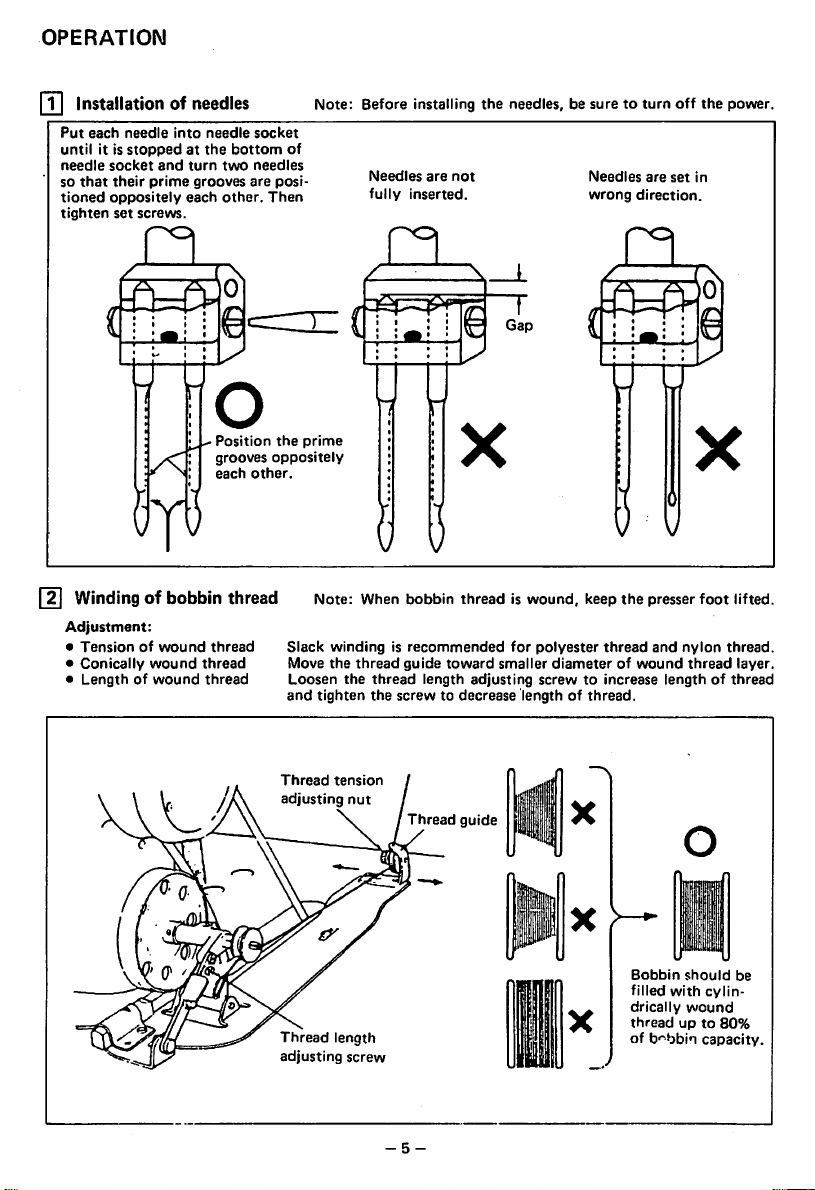
[T|
Installationofneedles
Put
each
that
it is
socket
oppositely
needle
stoppedatthe
and
their
prime
set
screws.
until
needle
so
tioned
tighten
into
each
needle
turn
grooves
bottom
two
other.
socket
needles
are
Then
posi
Note:
Before
installing
the
needles,besuretoturn
off
the
power.
of
Needles
are
fully
not
inserted.
Needles
wrong
are
set
direction.
in
Windingofbobbin
Adjustment:
•
Tensionofwound
•
Conically
•
Lengthofwound
wound
Position
grooves
each
thread
thread
thread
other.
thread
the
prime
oppositely
• I
()
8
Note: When bobbin thread is wound, keep the presser foot lifted.
Slack
windingisrecommended
Move
the
the
tighten
tension
length
thread
screw
thread
the
Loosen
and
Thread
Thread
adjusting
guide
toward
length
screwtodecrease
Thread
adjusting
guide
for
polyester
smaller
diameterofwound
screwtoincrease
lengthofthread.
thread
Bobbin
filled
drically
threadupto
of
and
lengthofthread
with
b'-bbin
nylon
thread
should
cylin-
wound
capacity.
thread.
layer.
be
80%
-5-
OPERATION
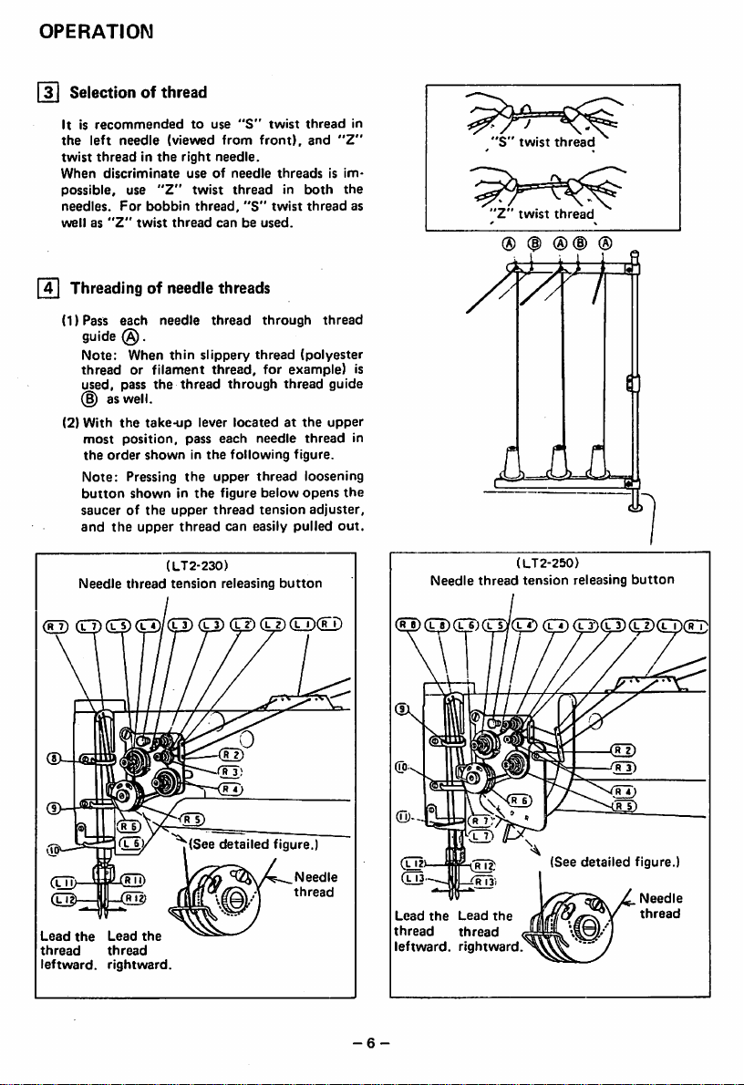
]
Selectionofthread
Itisrecommended
the
left
twist
When
possible,
needles.
wellas"Z"
fT)
(1)Pass
needle
threadinthe
discriminate
use
For
Threadingofneedle
each
guide
(§).
Note:
When
threadorfilament
used,
pass
as
well.
(2)
With
the
most
position,
the
order
Note:
Pressing
button
showninthe
saucerofthe
and
the
Needle
thread
(0>
(U
to
(viewed
right
useofneedle
"Z"
bobbin
twist
thread
needle
thin
the
thread
take-up
pass
showninthe
the
upper
upper
thread
(LT2-230)
tension
use
from
needle.
twist
thread,
canbeused.
threads
thread
slippery
thread,
through
lever
each
upper
figure
thread
can
releasing
"S"
twist
front),
threadsisim
thread
in
"S"
twist
through
thread
for
example)
thread
locatedatthe
needle
following
figure.
thread
below
tension
easily
pulled
button
CTTXr
thread
and
"Z"
both
the
thread
thread
(polyester
guide
upper
thread
loosening
opens
the
adjuster,
out.
0
in
as
"S"
'Z"
® (|)
twist
twist
thread
thread
®(D
®
is
in
thread
(LT2-250)
tension
releasing
button
Needle
(^CpCEI)
(ljI)—
Lead
thread
leftward,
(TT)/ 7(See detailed figure.)
(rTT)
the
Lead
the
thread
rightward.
Needle
thread
(See
detailed
figure.)
Needle
Lead
the
Lead
thread
leftward,
-6-
the
thread
rightward.
thread
OPERATION
Adjustment
reversing
Note:
To
the
feed
setting
dialtoa
®
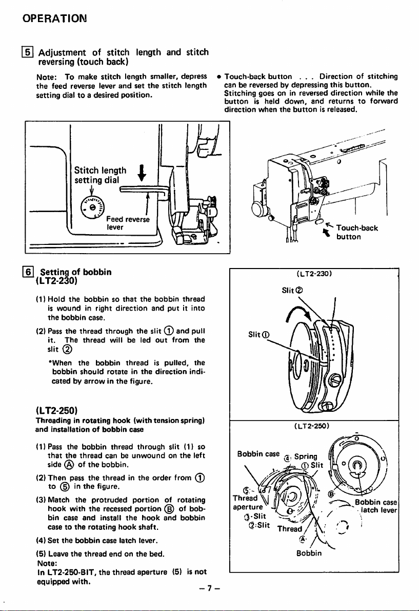
Settingofbobbin
(LT2-230)
(1)
Hold
is
woundinright
the
bobbin
(2)
Pass
the thread through the slit
it.
The
slit (2)
'When
bobbin
catedbyarrowinthe
of stitch length and stitch
(touch
back)
make
stitch
length
reverse
desired
Stitch
setting
the
bobbinsothat
case.
thread
the
should
lever
and
length
dial
Feed
lever
direction
willbeled
bobbin
rotateinthe
smaller,
set
the
position.
I
•
reverse
the
and
threadispulled,
figure.
stitch
bobbin
putitinto
(l)
out
direction
depress
length
thread
and pull
from
indi
•
Touch-back
canbereversedbydepressing
the
the
Stitching
buttonisheld
direction
goes
when
button
. . .
on in reversed
down,
the
buttonisreleased.
(LT2-230)
Directionofstitching
this
button.
direction
and
returnstoforward
while
Touch-back
button
the
(LT2-250)
Threadinginrotating
and
installationofbobbin
(1)Pass
the
that
side
(2)Then
bobbin
the
thread
(§) of the
pass
the thread in the order from
to (§) inthe figure.
(3)
Match
the
the
case
with
bobbin
the
with.
protruded
the
and
rotating
thread
the
hook
bin
casetothe
(4)
Set
(5)
Leave
Note:
In LT2-250-BIT,
equipped
hook
(with
case
thread
canbeunwound
through
bobbin.
portionofrotating
recessed
install
case
portion
the
hook
latch
endonthe
thread
aperture
shaft.
hook
lever.
tension
bed.
spring)
slit (1) so
on
the
of
and
bobbin
(5) is
bob
left
(T)
not
- 7 -
Bobbin
Thread
aperture
3-Slit
SSlit
(LT2-250)
case
Spring
0Slit
V
^
Thread
Bobbin
Bobbin
latch
case
lever

OPERATION
Ft]
Threadingofbobbin
il) Put
bobbin
the
(2) While holding the two needle threads by left
hand,
hand.
shownInthe
lifted.
shouldbealigned
thread
lugd)and
rotate
By
pullingupthe
Bothofbobbin
extenditbelow
Thread
the
figure,
threads
into the slit (j),
Opener
handwheel
and
the
thread
led
one
needle
bobbin
and
backward.
pass
the
bed.
Thread
turnbyright
threads,
threads
needle
under
will
thread
[9]
^
as
be
Balance
Needle
Needle
referencetobobbin
To
sion
Needle
special fabric and
and
of thread
AO
CX
threadtension
thread
adjust
needle
adjusting
strokeofthread
thread
nut.
tension
tension
Tight
bobbin
Loose
bobbin
tension
thread
thread
canbealso
thread
takeupspring.
Balanced
should
tension
needleorloose
tension
needleortight
tension
be
tension.
tension,
by changing intensity
adjusted
turn
adjusted
each
in
ten
for
81 Tension adjusmtnet of bobbin threads
Loosen
Tension
adjusting
screw
Tighten
[Til
Adjustmentofpresser
Pressuretofabric(s)
pressure
-8-
Loosen
adjusting
screw.
Strong
Tighten
foot
canbe
adjustedbyturning
L
Weak
Thread
adjusting
pressure
Pressure
screw
tension
nut
the
adjusting

OPERATION
12
Timing
* m *1 /Among Jhe followingeKplanotionsA
and
(DSet
(2)
(3)
•
Position
Adjust
centerofneedle
(1)
(2)
(3)
(4)
Note:Inthe
loosen
ingofhook
between
ncedla
motionrthosizoinuppeninetsforMITW
stitch
length
When
position,asshown
relationship
—The
1.6mmbelow
—The
centerofneedle
—Gap
faceofneedle
Needle/rotating
justedasfollows.
(For
that
dog assemblies
Lean
three
Turn
needleislifted
position.
Rotate
hook
Move
ward
hook
mm.
and
length
setting
dial.
needleislifted
shouldbemaintained.
upper
edgeofneedle
hook
point
between
easy
the
the
shouldbe0.05mm.
adjustment,
presser
are
adjustmentofhook
the
hook
pointsothatitcomestothe
axis.
the
machine
set screws of
the
balance
the
hookbyhandtoposition
pointtothe
the
hook
and
position
point
and
For
this
twoofC
adjustment,
shouldbeloosened.
adjustment,
set
screwsCand
shaft
gear
rotatinq
\and
to
the
hook
hook
the
iize
beneath
2.2mmfrom
the
following
point.
on
eye
It II
the
the
positional
should
shouldbelocatedatthe
axis.
hook
point
and
hook
foot,
position
throat
it is
plate
can
recommended
and
removed.)
point
head
backward
hook
wheel
2.2
mm
centerofneedle
bracket
it so
that
side
faceofneedleis0.05
do
always
and
lower
and
shaft
gear (small).
and
stop
when
from
the
axis.
leftwardorright-
gap
between
each
screws
not
excessively
maintain
shaft
gear.
motion
for
BIT.
stitch
lowest
the
side
be ad
feed
loosen
the
lowest
the
the
A,B
mesh
Gap
]
/
and
Needle
2.2
between
upper
mm
needle lowest ^
be
position
Center
needle
Set
screwofhook
shaft
gear
edgeofneedle
lift:
from
of
axis
Hook
(small)
0)
hook
point
point
0.05mm
eye
Set
screwoflower
shaft
gear
(large)
Set screw (A)
Set screw (A)
(5)
Tighten
(l)
While
against
tighten
After
and
Q)
Then
the
set
pressing
the
the
checking
the
tighten
screws in
the lowershaft gear
side
faceofhook
set
screwsCfirst.
gap
hook,
tighten
theset
the
following
between
the
screws
set
B.
bracket,
the
screws
order:
(large)
needle
A.
screw
Set screw (B)
9 -
Set
screw

OPERATION
•
Position
adjustmentofneedle
Adjust
needle
upper
edgeofneedle
1,6mmwhen
its
lowest
(1)
Remove
of
needle
bartoadjust.
(2)
After
positionsothat
eye
the
position.
the
bar
the
adjustment,
face
bracket
and
needleisliftedby2.2mmfrom
plate,
loosen
and
tighten
point
gap
the
hook
the
vertically
the
between
point
set
move
set screw.
the
screw
the
is
Needle
bar
(LT2-250)
•
Needle
vertical
Adjust
vertical
needle
barislocatedatits
II)
Remove
(2)
Rotate
needle
lequaltopitchofneedle
The
needle
turned
counterclockwise.
(3)
Return
before
the
screw
@ .
position
theset
one
position
clockwise,
the
adjustment
adjustment
position
turn
lifts
needle
of
needle
top
position.
screw
(§).
the
needle clamp,
canbechangedby0.6mm
bar
and
the
lowers
screw).
needle
when
when
clamptothe
and
retighten
after
thereby
clamp
position
the
one
turned
set
/Needle
bracket
Set
ILT2-230)
•
Needle
bar
_Set
screw
i
Needle
clamp
is
Lowers
Lifts
bar
screw
-•§
o
0
T
(LT2-250)
-
10

OPERATION
13| Adjustment of feed dog height
Height of feed dog and pressure of presser foot
should
be adjusted for individual fabric(s)
following
cautions:
♦
Fabric will be damaged if
too
high, or pressure of presser
♦
Even stitch length
cannot
the
be assured if the feed
dog is too low or pressure of presser foot is
small.
♦
Feed
point
dog height
where
the
needleisat
should
be measured at
feed dog
footistoo
the
top
with
extends
large.
too
position.
the
the
!
0.8mm
1.0mm
For
light
For
usual
For
heavy
Adjustment
(1)
Lean
(2)
Turn
the
feed
(3)
Loosen
(4)
Vertically
tion
adjustitto
(5)
After
set
screw.
The
feed
1
mm.
fabrics
fabrics
fabrics
procedure
the
machine
the
handwheelbyhand
dog
risestothe
the
feed
bar
move
the
Apprdx.
throat
Approx.
throat
Approx.
throat
head
set
feed
0.8mm
plate
1.0mm
plate
1.2mm
plate
backward.
and
maximum
screw.
bar
indicatedbyarrowinthe
the
adjustment,
dog
adequate
height.
tighten
heightisfactory-adjusted
(in
the
stop
the
figure)
feed
from
from
from
when
height.
direc
bar
2mm
to
Set
Feed
screw
bar
to
-11-

OPERATION
|l^
Relationship
motion
and
between
take-up
lever
rotating
motion
When the timing belt (cog belt) was removed for
its replacement, for example,
between
motion
rotating
shouldbeadjustedasfollows:
hook
motion
the
and
relationship
take-up
hook
lever
(1)Turn
take-up
(2)
Lean
sure
the
timing
the
bossofhook
(3) If
the
black
stallitagaintoadjust.
Relationship
15
opener
(1)Turn
when
remotely
(2)
Make
and
the
(3) If
the
opener
the
opener.
the
the
belt
timing
line,
balance
lever is
machine
arrow
lifted
head
(timing
is in line
shaft
markisnot
remove
wheel
to its
with
bearing.
the
between
motion
the
balance
the
from
sure
openerisapproximately
gap is
set
wheelbyhand
opener
holderislocated
the
throat
gap
between
too
large or small, loosen
screw@and
and
top
backward
mark)
the
in line
timing
hook
plate.
the
bobbin
adjust
stop
when
postion.
and
putonthe
black
line
with
belt
and
motion
and
case
0.2
mm.
position
make
and
stop
most
the
the
the
on
Timing
belt
in
Black
hook
Approx.
lineonboss
shaft
0.2mm
of
bearing
Timing
ng
belt
mark
sprocket
of
-12-
'
Opener
Screw(6*^
Opener
holder

OPERATION
Relationship
feed
dog
oThe
needle
at
the
(1)
Set
setting
(2)
Lean
(3)
Loosen
between
motion
feed
dog
can
plunge
centerofthe
stitch
dial.
the
machine
the
lengthto"0"onthe
and(^.
(4) Lower
(5)
(6)
(7) If the connection is
(8)
the
needletothe
Adjust
the
bar
and
the
tentatively
of
the
feed
shaft
Check
that
nected
with
in
Figure.
move
the
and
arrow
After
tighten
back
move
the
directiontoadjust.
the'completionofadjustment,
the
screws@,(§)and
needle
motion
(LT2-230)
shouldbeadjustedsothat
into
the
feed
dog
stitch
set
needle
screw
feed
hole.
shaft
head
backward.
crank
lowest position.
distance
tighten
the
the
needle
the
crank.
right
feed
linkatright
cover,
needle
between
bartobe
the
screws@and
shaft
crankiscon
angle,asshown
not
at right angle, re
loosen
the
bar
rocking
13.5,
screw
rodinthe
©.
and
the
hole
length
pressure
and
@
fully
Screw
Screw
Feed
crank
/
shaft
(middle)
Feed
crank
shaft
(right)
Needle
rocking
bar
rod
Needle
bar
Pressure
bar.
Feed
shaft
crank (right)
-13-
Screw®
Screw
Needle
rocking
©
bar
rod

OPERATION
Relationship
and
feed
•
The
feed
needle
can
at
the
centerofthe
(1)
Set
stitch lengthto"0"onthe
setting
(2)
Lean
the
(3)
Loosen
between
dog
motion
dog
shouldbeadjustedsothat
plunge
dial.
machine
the
feed
into
hole.
head
shaft
(LT2-250)
the
backward.
crank
needle
feed
dog
stitch
set
and@.
(4)
Lower
the
needletothe
(5) Adjust
(6)
(7) If
(8)
the
bar
tentatively
of
the
Check
nected
in
Figure.
the
move the back cover, loosen the screw (£}
and
the
figuretoadjust.
After
tighten
distance
and
the
needle
tighten
feed
shaft
that
the
right
with
the
connectionisnotatright
move
the
Linkinthe
the
completionofadjustment,
the
screws
lowest
between
bartobe
the
screws
crank.
feed
linkatright
(§),(§)
position.
the
14.1,
shaft
crankiscon
angle,asshown
angle, re
arrow
direction
and
(6).
motion
needle
length
screw
pressure
and
fully
the
and
hole
of
Screv
Screw
Feed
crank
shaft
(middle)
Feed
shaft
Srank (right)
Link
Pressure
bar
Needle
bar
„ [
Feed
shaft
crank (right)
Screw
-
14
Screw©
Link
S i
(D-lr™7

OPERATION
17
Needle bar (left or right)
(LT2-250)
• The stop lever should be set to
tion.
stop
operation
"L"or"R"
posi
Note: Although the
stop
lever can be operated
during sewing operation, it is recommended for
safe operation
that
the sewing machine is
stoppped with the take-up lever at nearly its
top
(1)
(2)
(3)
position
Left
Move
the
Right
Move
the
Two
needle
the
left
needle
needle bar
the
right
needle
and
bar
stop
stop
needle
bar
the
lever is set.
stop
lever to
bar.
stop
lever to
bar.
operation
operation
"L"
operation
"R"
positiontostop
positiontostop
To change single-needle (left or right) ope
rationtodouble-needle
the push lever backward. The
automatically
double-needle
]
Relationship
returnto"0"
operation
between
operation,
becomes
stop
position
depress
lever will
and
possible.
angleofcorner
stitching and stitch length
(Din
order
to
assure
neat
corner
stitch
length
ference to angle of
shouldbedetermined
corner
stitching
following table (applicable only to 1/4
needle
(2) By
width).
determining
stitch
ing for a given angle of
numberofoutside
identified
from
the
corner
table.
length
corner
(3) Ex.: When stitch length of 40° corner stitch
ing is
determined
numberofstitchesis"6".
Relationship
between
stitch
length
onlyto1'4
46
3 7
30
2 5
2 1
1 8 1 3
1 5
1 2
and
needle
4
4 4
3 4 2 7
2.8
2 3 1 8 1 5
1 9
1 6
Angle of
corner
stitching
100
120
130^
140-
Number
30
40*
50'
60'
70'
BO"
90'
(applicable
stitches
ol
2 3
55
46
38
32
2 /
22
18
t 5
1 1
stitching,
from
of inside
stitching, the
stitches
to
2.9mm,
numberofstitches
width)
5
6
4 3 7
4.3
35
111]
23
2 2
1 9 1 6
1.5
1 3
1 3
in re
stitch
can
7 8
2 5
20
the
be
the
30
22
1 7
-15-
Number
of
stitches
Push
Angle
corner
(6)\
Stop
lever
lever
of
^
,

OPERATION
BD
Installationofmovable
1.
initial
positionofmovable
(1)
Turn
the
balance
(2)
Push
the
cam
(3)
Turn
the
balance
wheel.
the
cam
coming
the
thread
the
movable
fixed
knife,asshowninFigure
(4)
(5)
balance
Set
roller
Loosen
Adjust
the
wheel
follower
wheel
follower
out
from
trimmer
Bolt(g)
knife
knife
and
lower
cranksothat
until
the
crankatthis
the
cam
rocking
knifesothat
Thread
rocking
the
the
black
groove.
crank
the
and
trimmer
crank
needle
cam
mark
position
clamp
movable
tighten
bartothe
roller
pointonthe
withascrewdriver
the
enters
bolts
(A)
knife
end
bolts@and
lowest
into
arm
and(^.
slant
position.
the
thread
meets
temporarily
portion
(§)
the
protrudes
.
trimmer
white
cam
groove.
mark
pointonthe
preventing
0 —
0.5mmfrom
the
cam
2.
Gap
between
holder
stopper
(1)
Turn
reaches
(2)
With
press
wheel
extrernityofits
(3) Manually
tion
gap between
ner hook stopper to
screws
for this adjustment).
movable
the
balance
the
lowest
the
needleatthe
cam
follower
until
the
rotate
indicated by
the
(§)
and
Thread
trimmer
rocking
knife
and
bobbin
wheelbyhand
position.
crank,
movable
stroke.
the
inner
arrow
lowest
turn
knife
hookinthe
in Figure
until
position,
the
balance
reaches
and
movable knife and the in
about
0.2
(§)
shouldbeloosened
mm (the
crank
case
needle
direc
adjust
Boltd)
de
the
0 ~
Hook
0.5mm
Movable
positioner
Approx
Movable
knife
0.2mm
knife
Fixed
Screw®
Screw®
Inner
knife
hook
-16-

OPERATION
20| Adjustment of thread trimmer cam
(1) Turn the balance wheel by
(2) Maintaining
grooveofthread
(3) Turning
starts moving when
pointonthe
To
adjust,
Cam
groove
the
needle
trimmer
the
balance wheel by
arm.
loosen
two
position,
the
thread
Thread
hand
until the needles reach
depress
cam.
hand,
green mark
trimmer
Cam
crank
Screw
trimmer
the
cam
adjust the
pointonthe
cam
clamp
follower
Cam
roller
®
cam
the
lowest position.
follower
thread
balance wheel comes in line with
screws
Arm
crank
trimmer
® .
Black
point
and
cam so
mark
put
Green
that
point
the
cam
the
mark
u
roller
movable knife
the
black mark
Balance
J-
Li
into
wheel
the
-17-

OPERATION
Adjustmentofthead
(1)
Turn
the
balance wheel by
(2) Maintaining
grooveofthread
(3)
Turning
the
the
needle
trimmer
balance
tension
hand
position,
cam.
wheel by
regulator
until
the
depress
hand,
adjust
needles
the
cam follower
the
thread
reach
the
tension
lowest
crank
release
position.
and
put
camsothat
the
cam roller
close when the white mark point on the balance wheel comes in line with the black mark point
on
the
arm.
To
adjust,
loosen
two
tension
release
cam
clamp
screws
@.
(4)
Opening
the
To adjust, loosenthe
(5)
Make
Thread
tension
release
lever
Screw (A)
degreeoftension
convexed
portionofthread
fine
adjustmentbyloosening
discshouldbe adjusted with the
release
screws
(g) and draw the wire.
cam,asshowninFig.
thenut© .
Cam
follower
crank
Cam
roller
Arm
tension
Black
point
release
roller(§)mountedon
mark
white
point
(D
Roller(b)
Thread
release
cam
Thread
trimmer
cam Screw©
Nut©
mark
the
Balance
y
into
tension
Lf
the
disc
wheel
-18-

OPERATION
22 Adjustment of meshing pressure of movable knife and fixed knife
(11
Loosen
the
fixed
knife
bracket
clamp
bolt
@.
(2) Turn the
bolt®
Note: Since excess pressure causes large
(3) Move
Fixed
bracket
vertical
position
.
ming failure, adjust it so
the
movable knife
knife
and
adjusting
that
check
flISF
screw (§) to adjust
torque
meshing
to the thread trimming mechanism and trim
pressure
thread can be trimmed with minimum pressure.
that
the
thread
can be sharply
trimmed.
and thenrighten the
23
Sharpeningoffixed
When
the
it is
knives
very
Since
0))
Vertical
knife
dull,
the
difficulttosharpen
fixed
Fixed
position
knife
shouldbesharpenedasillustrated
the
knife
movable
adjusting
knife,
-19-
screw®
replaceitwithanew
Oil
stone
in Fig.
one
whenitdulls.

OPERATION
24
Adjustment
(1)
Replace
(Since
suretouse
(2)
Lean
(3)
Loosen
(4)
Remove
(5)
Loosen
hook.
(6)
When
(7)
Contact
link
(8)
Turn
(9)
Loosen
(10)
Depress
smoothly
(11)
Adjustmentofthe
(a)
Push
(b)
Turn
groove
(c) Push
trimmer
for
changeofneedle gage
the
throat
plate,
feed
dog
feed
and
dog
the
the
machine
throat
plate
those
specifiedbyus.)
head
and
backward.
two connecting link clampbolts(j).
the
spring
@ .
the
hook
the
needles
the
rocking
clamp
bolt(j).
the
balance wheel by
thenuts (§)and
the
cam
enter
the
cam
the
connecting
surface
the
cam
cam
Thread
trimmer
rockingcrank (©
Connecting
Hook
bracket
(left)
Screw®
bracket
and
follower
the
follower
(n)as
groove
link
clamp
hooks
have
cranks
(c)
and
hand
until
(H)
.
crank
® and
grooveofthread
cam
groove
and
cranksothat
rod
and
smallaspossible,
follower
crank
smoothly.
Screw
Bolt®
W
Stopper
screws
been
needle
are
adjusted,
@ to
the
trimmer
the
cam
the
adjust
again
Stopper
pin© ,
Thread
rocking
clamp.
special
parts
(§)
and
(g) and
install
the
stopper
needles reach
adjust
the
cam.
Then
roller
cam
roller
the
clearance
and
tighten
and
check
pin
Screw®
Hook
Connecting
Nut®
trimmer
crank®
designed
for
adjust
the
spring
pins
(§)
the
lowest
connecting
rod© sothatthe
tighten
enters
into
between
the nuts(g)and
that
the
cam
Cam
roller
Cam
groove
bracket
(right)
Spring
Nut®
rod(0
®
thread
gap
.
and
position.
the
nuts
the
the
roller
Thread
between
and
(G)
cam
groove.
cam
(H)
.
,Cam
crank
,
33
trimmer
trimming
each
tighten
and
roller
enters
follower
Thread
trimmer
cam
-
Lower
'f"®"
Cam
follower
crank
®
cam
cam
(0).
and
into
machine,
needle
the
connecint
roller
the
the
thread
be
and
can
cam
-20-

]
Wiper
adjustment
(1)
Set
stitch
length dialto"5"
sewing
machine
position.
(2)
Loosen
the
to
be
parallel
showninFig.
(3)
Loosen
the screw (§) and turn the wiper
shafttoadjustsothat
tipofwire
range
from
1.5mmto2mm.
(4)
Loosen
the
to adjust
point
2
shown
(5) Pass
(6)
Loosen
0.5
that
wiper.
mm
mm
nut
the
and
the
when
each
needle
the
screw
leftwardorrightwardtoadjust
thread
canbesecurely
and
with
the
needleatUP
screw@and
with
and
needle
(e)and
clearance
presser
the
linkispushedbyfinger as
thread
© and
adjust
the
bed
surface,
gap
between
pointiswithin
turn the screw®
between
foot
becomes
through
needle
move
hopkedbythe
the
the
stop
the
the
link
the
wiper
about
eye.
wiper
so
Screw®
as
a
Screw®
Wiper
shaft
Needle
Caution: For a gauge size over
replace
with
the
Approx.
separate
Screw©
Wiper
0.5mm
wiper
Screw
——Approx.
5/8"
shaft.
(16 mm),
Approx.
2
0.5mm
Needle
mm
Presser
-21
foot
Wiper
1.5~2.0
mm
Nut(D
Set
screw
0
Wiper
Link
-

ADJUSTMENT
I 1 I
"1—2
Needlestop position can be selected between "1—POSITION" and "2-POSITION".
AND
POSITION"
OPERATION
select
switch
OF
CONTROL
UNIT
_•
—1
When
the
pedal is kicked
I2 I
Pedal
operation
The
pedal
follows;
\
\
•T-2 POSITION"'
switch
setting
1
POSITION
2
POSITION
Pedal
operation
Notes; 1. Stitching speed can be changed by changingdegree of pressingdown of the pedal.
2. For automatic presser foot lift, use optional unit.
3.
I 3 I
Adjusting
1.
Adjusting
The
pedal
justed by
the coil spring to the lever. ^ ^
It should be noted that the lever may f
notbestoppedatpositionifthe
mark
t_mark
switch
setat "1
back
operation and
Pedal
operation
by heel.
Stop
"UP"
Stop
"DOWN"
"2-POSITION"
"1-POSITION"
POSITION",
resultant
Toe
with
position
with
motion
down
Neutral
needle
needle
position
thread is
at
at
trimmed
(stitching,
Light
Presser foot goes Presserfoot goes UPafter one
up
Presser foot goes Presser
up
inone turnof the
thread
Neutral
I
heeling
trimming
turn
(needle
trimming
and
and
foot
DOWNtoUP)
' 1 '
.J-i
Neutral (stitching
(DC
24V).
For
tackstitching.
the
pedaling
the
pedal
toe
use
forces
down
optional
force
control
toe down force can be ad- ^
changing
hooking
position
force
of ®
is
start
bn-..
LD-C2, C4or06.
position)
LE-FM-1
Neutral
or LE-FM-2. or solenoid valve
» ^
sewing
needle
Neutral
Full
thread
goes UP
machine
motion)
4
heeling
trimming
after
B A
and
when
holf
thread
the
are as
2.
Adjusting
To adjust,
.,g„_
After
(see
Fig.
the
pedal
loosen
the
adjustment,
6).
heeling
force
nut "A" and turn bolt ^
tighten
nut
"A"
Coil
/ " \
/DECREASE—INCREAS^
spring
Fig. 6
Adjusting
x "
the
pedal pressing
Lever
down
force

ADJUSTMENT
I 4 I
Adjusting
1,
Adjusting
AND
OPERATION
the stitching speed
the
maximum
stitching
speed
OF
CONTROL
UNIT
(1) Adjusting the maximum speed (Maximum speed isthe speed achieved when the pedal is fully
pressed
down)
Two
variable resistors are available
the
control
variable
the
internal
setting
resistor
box
range from
resistor
Internal
3700
3000
"H"
The
within
Pole
2
pole
For
speed
variable
variable
The
Marks are put on
showninFig.7,for
For
fine
speed
adjustment,
•CAUTION*
(1)
Speed
faster
motor
pulley
S
eedsettin
inte^arVR^
and
the
resistoronthe
otherisone
the
"H".
variable
resistor
variable
resistor
rpm (LT2-230 MITW)
rpm
(LT2-250,
outofthe
the
than
diameter
adjustable
mustbechanged.
internal variable resistor
reference.
use a
that
setonthe
overacertain
2500spm
4500spm
for
adjustmentofthe
the
control
box
control
box
front
front
(external
low (minimum) speedtothe
"H"issetbyus
"H"
LT2.230
range of
setting
BIT)
the
when
external
the
External
"H"attwo
speed
meter
two
variable
diameter.
Speed
resistors
setting
external
maximum
panel.
VR)
permits
speed;
oneislocated
adjustmentofspeed
maximum speed set by
motorisshippedasfollows:
variable
resistor
adjustabe
Maximum
variable
speed~250
resistor,
the
settingofinternal
points (2,500 rpm and
cannotbeachievedbyincreasing
"1—2
POSITION"
variable
resistor
the
rpm
4,500
select
\
in
internal
range
rpm), as
switch
'M"
(Medium)]
I
(2) Adjusting
slightly)
The
positioning
Speed
when
turned
The
positioning
by
us).
(3)
Adjusting
The
internal
The
speed
turned
Since
thread
manualofthe
ming
speed.
(4)
Adjusting
When an
(medium
"H"
(Hjghl
"L"(Low)|
SPEED
the
low speed (Positioning speed is
increases
counter-clockwise,
speed
when
counter-clockwise.
speedisadjustable
the
thread
variable
increases
trimming
sewing
the
barracking
operation
speed)
can be
(Thread
trimming)
1
(low
the
internal
trimming
resistor
"T"
when
the
(setto200
speed
machineorconsult
speed
box,
LD-C2, C4orC6
adjustedbythe
speed)
canbeadjustedbythe
variable
withinarange
speed
permits
variable
may
adjustmentofthread
resistor
rpmbyus).
differ
from
our
internal
the
speed when the pedal is pressed
resistor
"L"isturned
from
160
"T"isturned
machinetomachine,
service
agency
(option)
is used
variable resistor
internal
rpmto320
trimming
clockwise,
for
for
variable resistor
clockwise,
rpm
speed.
and
refertothe
readjustmentofthread
barracking,
"M".
barracking
end
decreases
(setto250
decreases
instruction
down
"L".
rpm
when
trim
speed

ADJUSTMENT
AND
OPERATION
OF
CONTROL
UNIT
15 I Optionalfunctions
By connecting external (optional) control signal to the option connector, and setting the correspond
internal
DIP
switch,
various
For
details,
consult
with
optional
our
service
functions
agency.
canbeused.
Internal
(1)
Internal
COR :
+ 2
+ 1
S L
DIP
switch
DIP
switch
Correction
stitching
G :
Gain
switch
A : High-speed
stand
working
machine
external
available)
SH:One-shot
Slow
start
S L
+ 1
+ 2
ON.
ojllllllli
OFF
DC
8^-
+ +wii.^
stitching (high-speed
switch)
(tobesetat"ON")
stitching
(not
variable
function
control
switch
type
sewing
necessary
resistor
switch
switch
0
OFF
OFF
OFF
for
when
is
ON
OFF
X en CO m
O
to
CL D H
IL:Thread
switch
trimmer
interlock
release
POS : "1—2 POSITION" (thread trimming)
US : Needle
TB ;
FL : Automatic presser
1
stitch
ON
OFF
OFF
2
stitches
ON
ON
OFF
back
switch
Back
solenoid
trimming
"UP"
position
operationatthread
3
stitches
ON
OFF
ON
stopbytouch-
foot
lift (by
4
stitches
ON
ON
ON
Sj)
(2)
Automaitc
The
timingofautomatic
struction
Standard
timing
Needle
Needle
writteninthe
The
timing
"DOWN'
"UP"
Thread
wiper
thread
trimming
chart
trimmer'
sewing
is as
i ' •
i < I
I ' I
I I i
1
timing
thread
follows:
I I
!-+•
I I
-t-T
Needle
'DOWN"
chart
trimmer
machine
operation
settingupprocedure.
-24-
shouldbeadjustedinaccordance
—n
Needle
"UP"
with
the
in
r

ADJUSTMENT
(3)
Option
Various
For
contacts
AND
connector
external
necessary
OPERATION
controls
can be used by
for
input
OF
CONTROL
connecting
signal, use reliable
external
one.
UNIT
signaltothe
option
connector.
Speed
LOW
HIGH
•0
ov
Power
® (D
(5) (D
(§) (D
source
Option
HIglvspecd
opentMn
Low-speM
opeistnn
VeiiaMevoltage
Correction
sMcliinR
Needle
Speed control
cotivnand
Tlvead trimming
MediuiThSpeed
oneratton
OV
lifting
® (D
Clutch
© (D
Brake
1
9
8
7
6
S
4
3
2
1
(4) Reverse stitching by touchback switch
Touchback switch (S7) is operative only while the sewing machine is in operation.
f®®)
Synchr
onizer
Presser
OV
Pres^footUt
+ 30 V
Prespr loot tit
out^
External
resistor
Option
®{D(D
@®(D
®(D(D
Option
foot
variable
10kf2
1
1
2
3
4
~©
@®(D
®(0)®
Operation
POSITION"
•&
box
1
®®@
®
(g)(Q)®
Presser
Sewing
foot
machine
Sewing
machine
Toudiliackoutput
+
30
V
OV
Touchback
itgnil
—
—
Thgid^uijigiiog
OV
Thread
trimming
output
+
30
Wiparoutput
GND
12
II
10
9
8
7
6
5
4
3
V
2
1
Sewing
machine
body
-25
-

CAUTION;
Whenaneedleofsmall
Threading
for
light fabric stitching
gauge
(below
#11) is used,each
needle
thread shouldbe wound about 3/4 turn
around needle and then passed through needle eye, as shown below, to assure neat stitches. It is re
commendedtouse
stepped
needle.
-26-

(Caution)
AdjustmentofNeedle
Stop
Position
(LT2-230-B1T, LT2-250-B1T)
The machines, LT2-230-B1T and LT2-250-B1T, are shipped out after completion of the
sewing
and thread
bobbinonthree-folded
Itis necessary to adjust the needle
the
thickness
fabrictobe
Adjustment
Check
the
arm
when
the
1.
When
the
2.
When
the
and
sewn.
distance
needle
needle
needle
trimming
materialofthe
Follow
between
tests with the thread of
denim
(0.8mminthickness).
the
the
stops
at UP
stop
early;
4
stop
late;
stop
used
adjusting
white
position
vinyion
No.B
for both the
position after the thread is trimmed according to
sewing
thread,
and
the
procedure
markonthe
after
the
If
the
the
needle
left
mentioned
balance
fabric is
distanceAshown
malfunctionofthe
threads
and
right
thickness
wheel
sewn
and
sides)
below.
and
and
the
are
and
the
the
thread
left
knives
bobbin
not
trimmed
materialofthe
black
markonthe
is trimmed.
is 2mmor
occur,
threads
needle
properly.
and
more,
(at
and
the
the
3.
Adjusting
If
the
needle
synchronizer
within 5 mm
of Needle Bar
sureofthe
stop
Method
stop
position is deviated as
detector
according
Stop
discsothat
to the adjusting
Position, on the
position after
the
£\
the
sewing
distance
page
If
the
the
throat
shown
A may be within 2 mm
procedure
2of
the
and
the
-27
-
distanceBshown
clearance
plate
between
becomes
above, adjust
mentioned in the secion
the
left
the
narrow.
setting
and
is 5mmor
needle
location of
the
distance
[T],
Adjustment
and
more,
the
the
Instruction Manual. In adjusting, make
thread
trimming is actually completed.
8

SPECIFICATIONS
SpecificationsofLT2-230
Model
Spec.
Application
Stitching
speed
(Max.)
Stitch
length
Needle
bar
stroke
Presser
foot
storke
Needle
Rotating
hook
(for
thread
trimmer
use)
Bobbin
case
Bobbin
Thread
trimming
method
Lubrication
Automatic
Bed
Notes;•Feed
size
back
designed
•
Bobbin
dog,
throat
for
shouldbeof
and
LT2-230-M1TW
Medium-heavy
4000
spm
0~4
mm
33.4
DP X 5
Full-rotation,
lubrication,
hook,
prevention
Aluminum
trimmer
plate,
thread
LT2-250
3500
spm
5
mm
mm
Knee
Hand
equipped
spring
bobbin
use
timmer.
high
LT2-250-M1TW
fabric
3500
spm
0~-4
mnr
32.0
lifter:9mm
lever:7mm
#14
(#11~#18)
automatic
horizontal
with
racing
Fquipped
spring
for
Combinationoffixed
rotating
quality
mm
type
thread
hook,
free
5
3000
spm
mm
with
Automatic
bobbin
from
LT2-230.B1T
3000
spm
0-6
mrr
35.0
mm
DP X 5
knife
Touch-back
517X178
deformation.
Medimu-heavy
2500
spm
7
mm
#18
full-rotation,
lubrication,
hook,
prevention
Aluminum
trimmer
and
lubrication
mm
case
and
LT2-250-B1T
3000
spm
0~6
mm
Knee
lifter:13mm
hand
lever:7mm
(#14~#21)
equipped
bobbin
use
movable
bobbin
2500
spm
7
mm
automatic
horizontal
with
spring
Equipped
spring
knife
fabric
32.0
for
LT2-250:A1T
3000
spm
5
mm
mm
type
raching
with
thread
shouldbethose
A
MITSUBISHI
MEAD
0*FiCt
MITSUBISHI
OENICI
ELECTRIC
BLOC
MARUNOUChi
TOKYO
CORPORATION
iOO
TELEX
J24$32
CABLE
MElCO
TOKrO
A180E016P05
PrintedinPapan
 Loading...