

Page 1
MITSUBISHI
INDUSTRIAI.
MACHINE
LT2-2230
Double-Needle
Needle
Lockstitch,
Undertrimmer,
A
SEWING
Model
Classes
feed
Automatic
Variable
INSTRUCTION
Speed
MANUAL
Page 2
PRECAUTIONS
(1)
Safety
1. Keep your
area
2.
Power
operator
Precautions
hands
around
the
mustbeturned
leaves
and
pulley
his/her
BEFORE
fingers
when
off
when
seat.
STARTING
away
from
turning
the
the
area
the
power
machine
TO
around
on.
is not in
OPERATE
the
needle
use,orwhen
3. Power must be turned off before tilting the machine head, installing or
removing
4. Avoid placing fingers, hair, bars etc.,
winder, or motor
5. Do
needle, or pulley
6. Ifa belt cover, finger guard,
the
(2)
Precautions
1. If
the
filling it.
2. If
the
lubricating.
3. When a
direction of
.(Thepulleyshould rotate counterclockwise
4. Verify
machine
(3)
Precautions
the
not
insert
machine
before
machine's
"V" belt, adjusting
when
the
fingers
without
when
Starting
oil
pan
into
the
these
has
the
machine, or replacing its parts.
near
the
pulley, "V" belt, bobbin
machine
the
machine
and/or
safety
Operation
is operating.
thread
is operating.
eye guard
devices.
take-up
cover,
are
an oil sump, never operate
machineis lubricatedbya drop oiler, never operate
new
sewing machine is first turned on, verify
the
pulley
with
the
power
on.
when
viewed from the pulley.)
the
voltage
nameplate.
for
and
Operating
(single or three)
Conditions
phase
with
under/around
installed, do not operate
the
machine before
the
machinebefore
the
those
given on
1. Avoidusing the machine at abnormally hightemperatures (35°C or higher)
or low
temperatures
2. Avoid using
the
(5°C or lower). Otherwise, machine failure may result.
machine in dusty conditions.
and
the
the
the
rotational
the
Page 3
-CONTENTS-
PREPARATION
m
Power
[2
Connectionofcontrol
cable
FOR
OPERATION
connection
box
[Tl Adjustment of needlebar stop position 3
CAUTIONS
m Oiling (2) 4
r2l Oiling condition and adjustment on oiling to
m
ON
USE
Adjustmentofoilingtorotating
hook
thread
take-up lever 5
IT] Cautions on operation 5
OPERATION
Installationofneedles
Winding of
Selectionofthread
Threadingofneedle
bobbin
thread
threads
Adjustment of stitch length and stitch reversing (touch-back) 8
Settingofbobbin
Adjustment of needlethread guide 8
Threadingof bobbin threads 9
Tension adjustment of bobbin threads 9
Balance of
10
Needle
11
Adjustment of presser foot pressure 9
12
Timing between rotating hook motion and needle motion 10, 11
13
Adjustment of feed dog height 12
14
Relationship between rotating hook motion and take-up lever motion 13
15
Relationship between hook motion and opener motion 13
16
Relationship between needle motion and feed dog motion 14
17
Installationofmovable
thread
thread
tension
tension
knife
Adjustment of thread trimmer cam 16
Adjustment of thread tension regulator 17
Adjustmentof
meshing
pressureof movableknife and fixed knife 18
Sharpening of fixed knife 18
Adjustment for change of needle gage 19
Wiper
adjustment
1
2
5
6
6
7
7
8
9
9
15
20
ADJUSTMENT
m
"1-2
m Pedal
m Adjusting
AND
POSITION"
operation
the
pedaling forces
OPERATION
select
switch
OF
CONTROL
operations
UNIT
21,24
21,24
21,24
m Adjustingthe stitchingspeed 22,25
fSl Optional functions 23, 26, 27
CAUTION
28
Page 4
PREPARATION
•
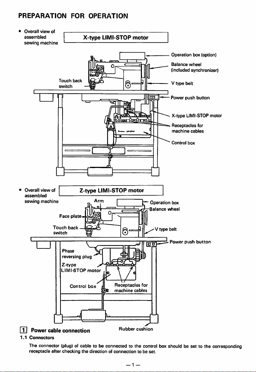
Overall
view
assembled
sewing
of
machine
FOR
OPERATION
X-type
LIMI-STOP
motor
•
Overall
assembled
sewing
view
of
machine
Touch
Touch
switch
Face
switch
back
plate
back
Phase
reversing
Z-type
LIMI-STOP
Control
Z-type
plug
motor
box
LIMI-STOP
Arm
motor
13
Receptacles
machine
for
cables
Operation box
Balance
^^vtype
Operation
Balance
box (option)
wheel
(included synchronizer)
V type belt
Power
push
button
X-type LIMI-STOPmotor
Receptacles
machine
Control
wheel
Power
box
push
for
cables
button
rn
Powercable connection
1.1
Connectors
The connector
receptacle
(plug)
after
Rubber
cushion
of cable to be connected to the control boxshould be set to the corresponding
checking
the
direction of
connection
— 1 —
to be
set.
Page 5
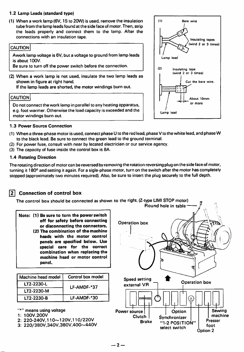
1.2
Lamp
(1)
Whenawork
tube
the
connections
CAUTION
Awork
is
about
Be
suretoturn
(2)
When
shown
If
the
Leads
(standard
lamp
from
the
lamp
leads
properly
withaninsulation
lamp
voltage is 6V, but a voltage to
10OV.
off
(6\/, 15 to
leads
and
the
power
type)
found at
a work lamp is not used,
in figure at right
lamp
leads
are
hand.
shorted,
20W)isused,
connect
tape.
switch
the
remove
from
connection.
the
two
the
lamp. After
lamp
lamp leads
burn
the
sideface ofmotor. Then,strip
themtothe
ground
before
the
insulate
motor
windings
insulation
the
leads
out.
Insulating
(wind
Lamp
lead
12)
Insulating
tape
as
(wind2or3times)
Cut
tapes
2 or 3
times)
the
bare
wire.
CAUTION
Do
not
connect
e.g. foot
warmer.
motor
windings
1.3
Power
Source
(1)
Whenathree-phase
to
the
(2) For
(3)
1.4
black lead. Be
power
The
capacityoffuse
Rotating
fuse,
Direction
the
work
lampinparalleltoany
Otherwise
burn
out.
Connection
motor is used, connect
suretoconnect
consult
with
inside
heating
the
load capacity is
phase
the
green
by lecated electrician or our service agency.
box is 8A.
the
near
control
apparatus,
exceeded
Uto the red lead,
lead to
the
and
ground
the
phase
terminal.
Lamp
Vto
/
lead
the
About
or
more
white lead, and
10mm
phase
Therotating directionof motorcan bereversed byremovingthe rotation reversing plugon the side faceof motor,
turning it
stopped (approximately two minutes required). Also, be
[n
180°
and setting itagain. Fora sigle-phase motor, turn on the switch after the motor has completely
Connection of control box
The
control
box
shouldbeconnectedasshowntothe
Note:
(1) Be
suretoturn
off
for
safety
or
disconnecting
(2)
The
combinationofthe
heads
panels
special
combination
machine
panel.
before
with
the
are
specified
care
for
when
headormotor
the
the
motor
power
connecting
connectors.
machine
control
below.
the
correct
replacing
control
switch
Use
the
sure
to insert
the
plug securely to the fulldepth.
right. (Z-type LIMISTOP motor)
Round
holeintable-
Operation
box
W
Machine
1;
2:
3:
head
model
LT2-2230-L
LT2-2230-M
LT2-2230-B
means
using
100V.200V
220-240V,110~120V,110/220V
220/380V,340V,380V,400~440V
Control
LF-AMDF-*37
LF-AMDF-'30
voltage
box
model
Power
— 2 —
Speed
external
source
setting
Clutch
VR
Brake
Option
Synchronizer
"1-2
POSITION"
select
switch
Operation
box
Option
Sewing
machine
Presser
foot
2
Page 6
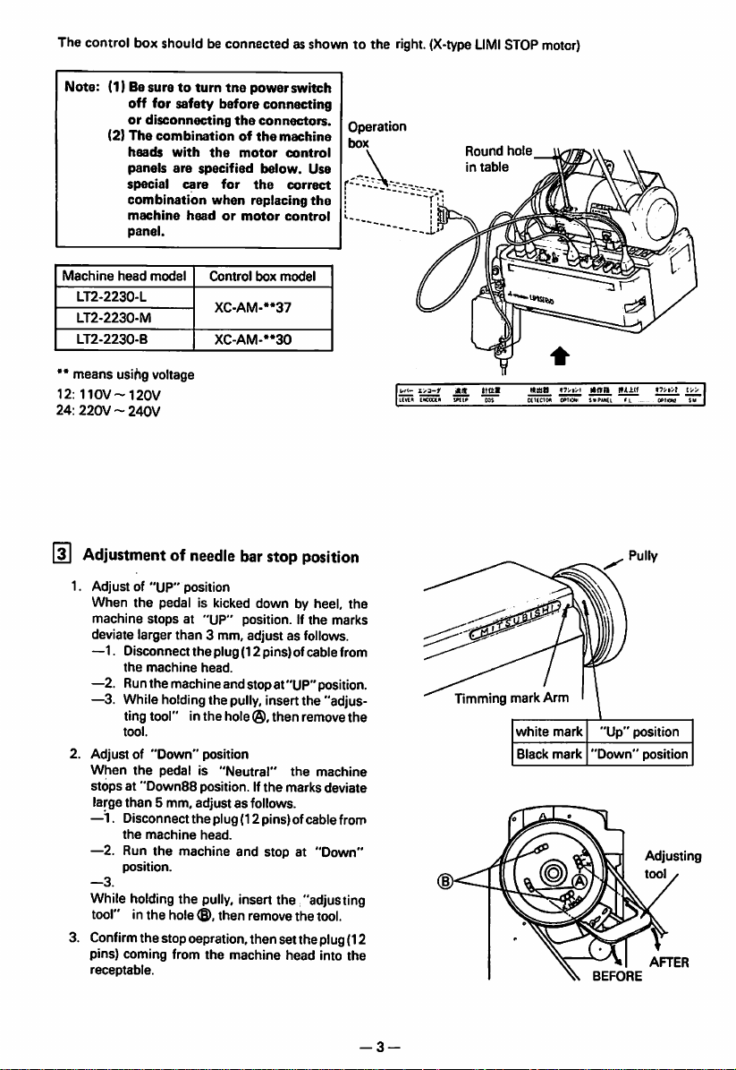
The control box should be connectedasshown to the right.
(X-type
LIMI
STOP
motor)
Note: (1) Besuretoturn
off
for
or
disconnecting
(2)
The
combinationofthe
heads
with
panels
are
special
combination
machine
panel.
Machine
••
12:
24:
[3]
head
model
LT2-2230-L
LT2-2230-M
LT2-2230-B
means
usihg voltage
110V--120V
220V~240V
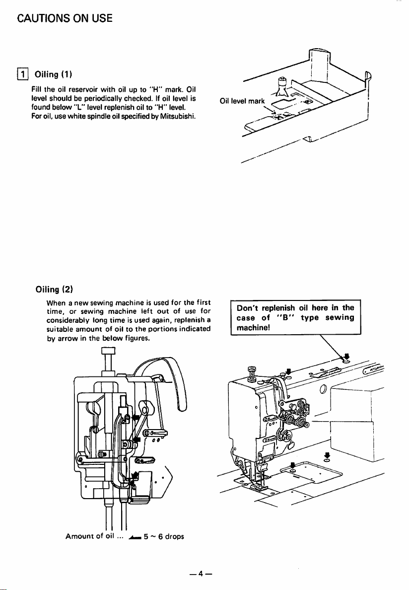
Adjustmentofneedle
tne
safety
before
the
the
specified
care
for
when
headormotor
Control
XC-AM-»*37
XC-AM-**30
power switch
connecting
connectors.
motor
below.
the
replacing
box
bar
stop
1. Adjust of "UP" position
When
the
machine
deviate larger
—1. Disconnect
pedal is kicked down by heel,
stopsat"UP"
the
machine
than
position. If
3 mm, adjust as follows.
the
plug (12 pins) ofcable from
head.
—2. Runthemachineandstop at"UP"position.
—3. Whileholdingthe
ting tool" in
tool.
2. Adjust of
When
stops
large
—1. Disconnect
—2. Run
—3.
"Down"
the
pedalis"Neutral"
at "DownSBposition. If
than
5 mm,
the
machine
the
position.
pully,
the
insertthe "adjus
hole®,then
position
the
adjustasfollows.
the
plug (12 pins) ofcable from
head.
machine and stop at "Down"
While holdingthe pully, insert the "adjusting
tool" in
the
hole
<B),
then
remove
3.
Confirm
thestopoepration, then setthe plug(12
pins)
coming
from
the
receptable.
machine
machine
control
Use
correct
the
control
model
position
the
remove
the
marks
the
head
Operation
box
the
marks
the
machine
deviate
tool.
into
the
Round
hole
in
table
a-f
Alt
UvlR
ENCOCCM
ttal
iPtlfi
Pully
Timming mark Arm
white
mark
"Up"
position
"Down"
BEFORE
position
Adjusting
tool
AFTER
Black
mark
— 3 —
Page 7
CAUTIONS
rn
Oiling
Fill
level
found below "L" level replenish oilto "H" level.
For oil,
the
oil reservoir
should
use
ON
USE
(1)
with
be periodically
white
spindleoil specified by Mitsubishi.
oil up to
checked.
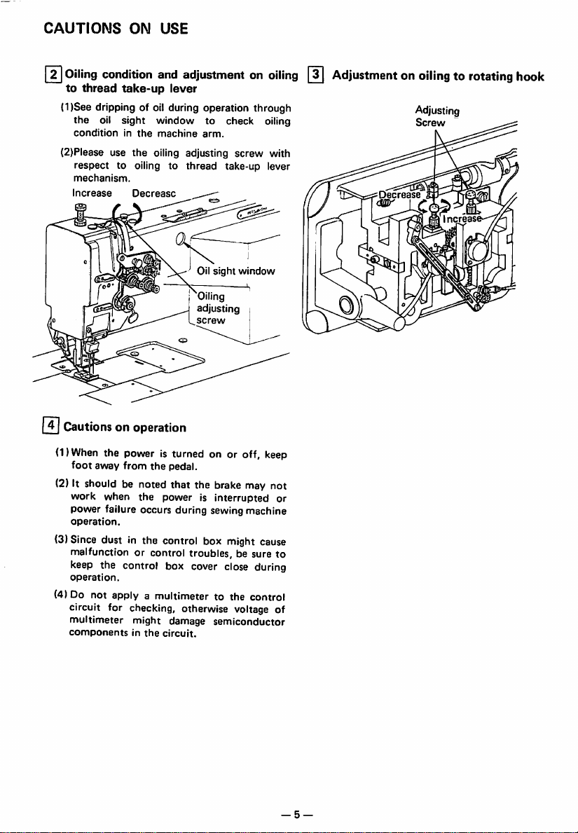
Oiling (2)
When a
new
sewing
time,
or sewing
considerably
suitable
amountofoiltothe
by
arrowinthe
machineisused
machine
long
timeisused
below
left
figures.
"H"
mark. Oil
If oil level is
for
out
again,
portions
the
of use
replenish
indicated
first
for
Oil
level
Don't
replenish
case
a
of
machine!
"B"
oil
hereinthe
type
sewing
Amount
of oil ... 5 ~ 6
drops
— 4 —
Page 8
CAUTIONS
[Tl
Oiling
to
thread
ON
condition
take-up
USE
and
adjustmentonoiling
lever
(1)See dripping of oil during operation through
the
oil sight window to check oiling
conditioninthe
(2)Please use
respect
mechanism.
Increase
@
Cautionsonoperation
machine
the
oiling adjusting
to oiling to
Decrease
arm.
thread
Oil
Oiling
adjusting
screw
screw
take-up lever
sight
window
with
Adjustmentonoilingtorotating
Adjusting
Screw
ecrease
Increas
hook
(DWhen the power is turned on or off, keep
foot
away
from
the
pedal.
(2) It should be noted that the brake may not
work
when
the
power is interrupted or
power failure occurs during sewing machine
operation.
(3)Since dust in the control box might cause
malfunction or control troubles, be sure to
keep the control box cover close during
operation.
(4) Do not apply a multimeter to the control
circuit for checking, otherwise voltage of
multimeter might damage semiconductor
components
in
the
circuit.
-5
—
Page 9
OPERATION
pn
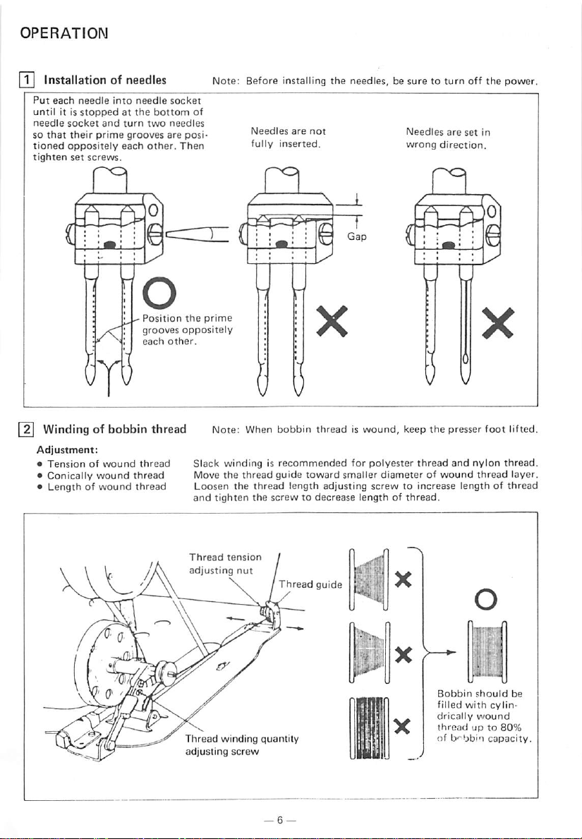
Installationofneedles
Put
each
that
it is
socket
oppositely
needle
stoppedatthe
and
their
prime
set
screws.
until
needle
so
tioned
tighten
into
each
needle
turn
grooves
bottom
two
other.
socket
needles
are
Then
posi
Note:
Before
installing
of
Needles
fully
inserted.
the
needles,besuretoturn
are
not
Needles
wrong
are
set
direction.
off
the
power.
in
n
Windingofbobbin
Adjustment:
•
Tensionofwound
•
Conically
•
Lengthofwound
wound
O
Position
grooves
each
thread
thread
thread
other.
thread
n
the
prime
oppositely
Note: When bobbin thread is wound, keep the presser foot lifted.
Slack
windingisrecommended
Move
the
the
tighten
tension
thread
nut
thread
the
Loosen
and
Thread
adjusting
guide
toward
length
screwtodecrease
Thread
adjusting
guide
for
polyester
smaller
diameterofwound
screwtoincrease
lengthofthread.
thread
and
lengthofthread
nylon
thread
thread.
layer,
m
Thread
adjusting
winding
screw
quantity
Bobbin
should
filled
with
drically
wound
threadupto
of b-^bbin
be
cylin-
80%
capacity.
Page 10
OPERATION
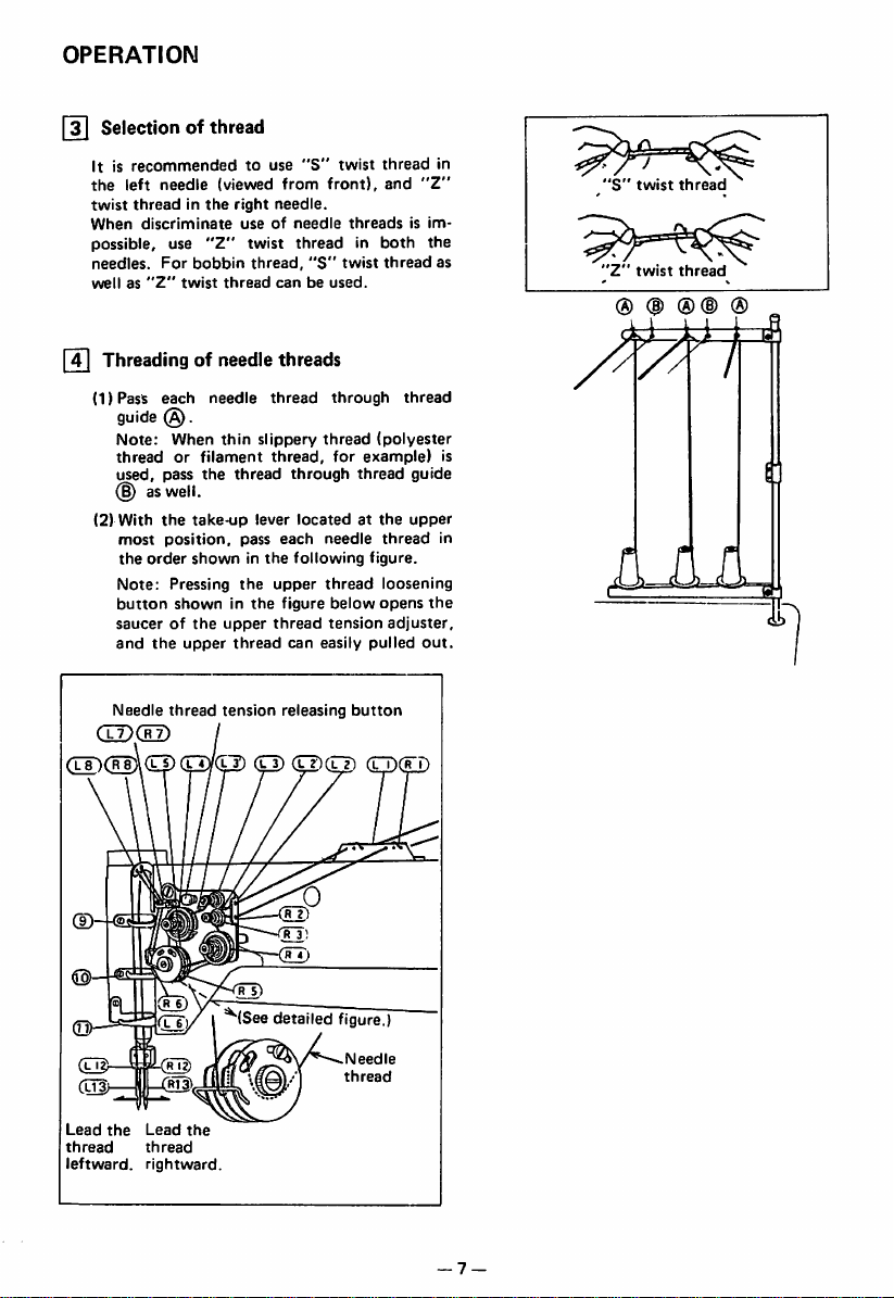
[3] Selection of thread
It is
recommendedtouse
the
left
needle
use
"Z"
For
bobbin
twist
each
needle
@.
When
pass
the
the
take-up
position,
showninthe
Pressing
showninthe
the
upper
(viewed
right
useofneedle
twist
thread
thin
thread
pass
the
upper
thread
twist
threadinthe
When
discriminate
possible,
needles.
wellas"Z"
[T]
Threadingofneedle
(1)
Pass
guide
Note:
threadorfilament
used,
(J)aswell.
(2)
With
most
the
order
Note:
button
saucerofthe
and
"S"
from
needle.
threadinboth
thread,
"S"
canbeused.
threads
thread
slippery
thread,
through
lever
locatedatthe
each
following
upper
figure
thread
can
twist
front),
threadsisim
twist
through
thread
for
example)
thread
needle
figure.
thread
below
tension
easily
pulled
thread
and
"Z"
the
thread
thread
(polyester
guide
upper
thread
loosening
opens
the
adjuster,
out.
in
as
S
twist
Z '
twist
® (1)
thread
thread
®(D
®
is
in
Needle
GDdD
(IT)(rJ)\(0)
Lead
the
thread
leftward,
Lead
thread
rightward.
thread
Ck
the
tension
releasing
kD
(kD
(0)(0)
^(Seedetailed
button
figure.)
Needle
thread
— 7 —
Page 11

OPERATION
Adjustment
reversing
Note:
the
feed
setting
dialtoa
(touch
To
make
reverse
Stitch
setting
of
stitch
back)
stitch
lever
desired
length
dial
Feed
lever
[6! Setting ofbobbin
(1) Pull
out
5 cm
thread
(2)
Hold
the
bobbinsothat
in right direction
and
tail
put
length
length
and
set
position.
reverse
from
the
bobbin
it into
smaller,
the
^
the
bobbin.
threadiswould
the
hook.
and
stitch
stitch
depress
length
•
Touch-back
canbereversedbydepressing
Stitching
buttonisheld
direction
goes
when
Thread
button
on in
down,
the
buttonisreleased.
tail
. . .
reversed
Directionofstitching
this
button.
direction
and
returnstoforward
Touch-back
while
^ button
the
Ft]
Adjusting,of
Please
adjust
tensioner
Thread
guide
position
Materials
Needle
thread
supply
needle
needle
The
standard
More
Left
thicker
than
thread
accordingtosewing
thread
guide
of n'.^edle
condition.
Middle
Standard
guide
The
ner
standard
thread
Right
thin
than
Less
— 8
Page 12

OPERATION
[si
Threadingofbobbin
(1)
Put
bobbin
the lug (2) and extend it below the bed.
(2) While
hand,
hand.
showninthe
lifted.
shouldbealigned
thread
Thread
holding
rotate
the
the
By
pullingupthe
figure,
Bothofbobbin
threads
into the slit (j},
Opener
two
needle
handwheel
and
the
thread
led
one
needle
bobbin
backward.
pass
Thread
threadsbyleft
turnbyright
threads,
threads
and
needle
under
will be
thread
ITil
*
Needle
referencetobobbin
as
•Toadjust
sion
Needle
special
and
Balanceofthread
AO
BX
CX
Needle
threadtension
thread
tension
needle
adjusting
thread
fabric
strokeofthread
nut.
tension
and
thread
tension
Balanced
tension
po-i-r^
Tight
needleorloose
bobbin
tension
Loose
needleortight
bobbin
tension
shouldbeadjusted
thread
tension.
tension,
canbealso
threadbychanging
takeupspring.
Tighten
turn
adjusted
each
ten
intensity
in
for
Tension
Tension
screw
adjusmtnet
adjusting
of
bobbin
threads
Loosen
Tighten
12
Adjustmentofpresser
Pressuretofabric(s)
pressure
-9-
adjusting
Weaken
..
Thread
adjusting
foot
pressure
canbeadjustedbyturning
screw.
Tighten
tension
nut
the
Page 13

OPERATION
Timing between rotatina hook motion
and
needle
motion
(DSet
stitch length on
dial
shown
(2)
When
lowest position, the following positional relation
ship
—The
1.0
—The
centerofneedle
—Gap
faceofneedle
table.
needleislifted@shown
should
be maintained.
upper edge of needle eye should be
~ 1.6 mm
hook point should be located at the
between the hook point and the side
(3) Needle/rotating hook position can be ad
justedasfollows.
(For easy adjustment, it is recommended
that the presser foot, throat plate and feed
dog assemblies are removed.)
•
Position
adjustmentofhook
Adjust the hook point so that it comes to the
centerofneedle
ID Lean
(2) Turn the balance wheel and stop when the
the
three
machine
set screws of hook
needleislifted
lowest
(3)
(4) Move the
position.
Rotate
the
hook
pointtothe
ward and position it so that gap between the
hook
hook point and side face of needle is 0.05
mm.
For
this
and
two
of
the
stitch length setting
below
the
hook point.
axis.
shouldbe0.05mm.
axis.
head
backward
shaft
(§)mmshown
hookbyhand
center
of needle axis.
bracket
adjustment,
shouldbeloosened.
leftward or right-
each
table,
point
and
gear (small).
table
to position
screws
from
loosen
from
(§)
the
the
,(§)
the
--—.....^Cla^
Set
the
stitch
length
Needle
lift
Gap®
Clearance
©
Hook
Set screw of
shaft gear (small)
2.0
point
hook
-L
2
mm
-M
3
2.2
1.0~1.6
0.05
mm
mm
mm
-B
4.5
2.4
mm
Note:Inthe
adjustment,donot
excessively
loosen set screws©and alwaysmaintain mesh
ing of
hook
shaft
gear
and
lower
shaft
gear.
(5)Tighten the set screws inthe following order:
(j)
While
pressing
the
lower
shaft
gear
against the side face of hook bracket,
(large)
tighten the set screws(£)first.
@
After
(D
and the
Then
checking
tighten
gap
hook,
tighten
thesetscrews®.
between
theset
the
needle
screws@^
—10—
Set
screwoflower
shaft gear (large)
Set
screw
Set
screw
Q)
Set
screw
(B
Set
screw
Set
screw
\
®
Page 14

OPERATION
•
Position
adjustmentofneedle
point
Adjust needle position so that gap between the
upperedgeof needleeyeand the hookpointis(§)
mmwhen the needleIs
lowest positionshown Inbefore page.
(1)
Remove
of
bartoadjust.
(2)
After
needle
the
the
bar
adjustment,
face
bracket
lifted
plate,
loosen
and
vertically
tighten
by@ mm
the
the
set
from
set
move
screw.
screw
the
Its
0
-Needle
-Needle
bracket
Set
screw
bar
bar
—11
—
Page 15

OPERATION
55
Adjustmentoffeed
Height of feed dog
shouldbeadjusted
following
cautions:
♦
Fabric
will be
too
high,orpressureofpresser
♦
Even
stitch
dogistoo
small.
♦
Feed
point
length
loworpressureofpresser
dog
height
where
dog
height
and
pressure of presser
for
individual
damagedifthe
fabric(s)
feed
footistoo
cannot
be assured if
shouldbemeasuredatthe
the
needleisat
the
with
dog
extends
the
footistoo
top
position.
foot
the
large.
feed
2ZZ
TSi
22ZZr
!
0.8mm
1.0mm
For
light
For
usual
For
heavy
Adjustment
(1)
Lean
(2)
Turn
the
feed
(3)
Loosen
(4)
Vertically
tion
adjustitto
(5)
After
set
screw.
The
feed
1
mm.
fabrics
fabrics
fabrics
procedure
the
machine
the
handwheelbyhand
dog
the
move
indicated
adequate
the
adjustment,
dog
Approx.
throat
Approx.
.
throat
.
Approx.
throat
head
risestothe
feed
bar
set
the
by
arrowinthe
heightisfactory-adjusted
backward.
screw.
feed
height.
tighten
0.8mm
plate
1.0mm
plate
1.2mm
plate
and
maximum
bar
(in
the
stop
height.
the
figure)
feed
from
from
from
when
direc
bar
1.2mm
to
Set
Feed
screw
bar
to
—12—
Page 16

OPERATION
Relationship between rotating
motion
and
take-up
lever
motion
hook
When the timing belt (cog belt) was removed for
its replacement, for example, the relationship
between rotating
motion
shouldbeadjustedasfollows:
(1)Turn
take-up
(2)
Lean
the
sure
the
timing
the
bossofhook
(3) If
the
black
stallitagaintoadjust.
]
Relationship
opener
the
balance wheel
lever is
machine
arrow
belt
is in
timing
line,
remove
motion
hook
motion
liftedtoits
head
(timing
line
with
shaft
markisnot
the
between
and
top
backward
mark)
the
bearing.
in line
timing
hook
and
take-up lever
stop
postion.
and
putonthe
black
belt
motion
when
line
with
and
make
on
the
in
and
the
Black
hook
lineonboss
shaft
bearing
Timing
belt
ill
Timing
mark
Timing
belt
sprocket
of
(1)Turn
when
remotely
(2) Make
and
(3) If
the
opener
the
the
balance
the
from
sure
the
openerisapproximately
gap is
set
opener.
wheelbyhand
opener
the
throat
gap
between
too
largeorsmall, loosen
screw@and
holderislocated
plate.
the
bobbin
0.2
adjust
position
and
case
mm,
stop
most
the
of
—13—
Approx.
0.2mm
Opener Screw®
Opener
holder
Page 17

OPERATION
[T^
Relationship
feed
dog
oThe
needle
at
the
(1)Set
(2)
(3)
(4) Lower
(5)
(6)
(7) If
(8)
between
motion
feed
dog
can plunge
centerofthe
stitch
setting
dial.
Lean
the
machine
Loosen
the
and(^
the
Adjust
the
bar
and
the
tentatively
of
the
feed
Check
that
nected
with
in
Figure.
the
connectionisnot
move
the
and
move
arrow
directiontoadjust.
After
the
tighten
the
needle
shouldboadjustedsothat
into
the
hole.
lengthto"0"on
head
feed
shaft
needletothe
distance
needle
tighten
the
the
needle
the
crank.
right
feed
linkatright
cover,
(§), (§)
shaft
back
the
completionofadjustment,
screws
motion
feed dog needle hole
the
stitch
backward.
crank
set
screw
lowest position.
between
bartobe
bar
"the
13.5,
screws
(§)
shaft
crankiscon
angle,asshown
.at right angle, re
loosen
the
screw
rocking
rodinthe
and
©.
and
the
length
pressure
and
and
©
fully
(b)
Screw
Screw
Feed
crank
shaft
(middle)
Feed
crank(right)
shaft
'Needle
rocking
bar
rod
Needle
bar-
n..'5
Pressure
bar
Feed
crank
—14—
shaft
(right)
Screw®
Screw
Needle
rocking
©
bar
rod
Page 18

OPERATION
Installationofmovable
1.
Initial
positionofmovable
{1)
Turn
the
balance
(2)
Push
the
cam
(3)
Turn
the
balance
wheel.
the
cam
coming
the
the
fixed
knife,asshowninFigure
14)
(5)
balance
Set
roller
Adjust
the
Loosen
follower
follower
out
thread
movable
Bolt{g)
knife
wheel
and
cranksothat
wheel
crankatthis
from
the
trimmer
knifesothat
knife
lower
until
cam
rocking
Thread
rocking
the
groove.
trimmer
the
black
crank
the
and
crank
needle
the
cam
position
movable
tighten
bartothe
roller
mark
pointonthe
withascrewdriver
clamp
bolts@and
knife
the
lowest
enters
into
arm
end
slant
bolts@and
0 ~
0.5mm
position.
the
thread
meets
@.
portion
(§)
trimmer
the
white
temporarily
protrudes
.
Movable
mark
preventing
knife
cam
groove.
pointonthe
0 —
0.5mmfrom
Fixed
the
knife
cam
2.
Gap
hoider
(1)
(2)
(3)
between
Turn
reaches
With
press
wheel
extremityofits
Manually
tion
gap
ner
screws
for
movable
stopper
the
balance
the
the
cam
until
indicatedbyarrowinFigure
between
hook
@
this
adjustment).
wheel by
lowest
position.
needleatfhe
follower
rotate
crank,
the
movable
stroke.
the
inner
the
movable knife and
stoppertoabout
and
@
Thread
rocking
knife
and
bobbin
hand
until
lowest
position,
turn
the
0.2
balance
reaches
and
mm
knife
hookinthe
shouldbeloosened
trimmer
crank
case
needle
direc
adjust
the
(the
Bolt(D
de
the
in
—15
knife-
0.2
mm
^—-Screw
Screw
inner
hook
Movable
Hook positioner
Approx.
—
Page 19

OPERATION
|l^
Adjustment ofthreadtrimmer cam
(1)
Turn
the
balance wheel by
(2)
Maintaining
grooveofthread
(3)
Turning
starts
pointonthe
To
adjust,
Cam
groove
the
moving
loosen
the
balance
when
arm.
needle
position,
trimmer
wheelbyhand,
the
two
thread
cam.
green
hand
mark
trimmer
until
the
depress
adjust
pointonthe
cam
Cam
crank
Cam
Screw
needles reach
the
cam
the
clamp
follower
roller
@
follower
thread
balance
screws
the
lowest
crank
trimmer
wheel
@
position.
and
camsothat
comes
Green
mark
Black
point
put
in line
the
point
mark
cam
the
with
roller
movable
the
black
Balance
into
knife
mark
wheel
the
Thread
trimmer
cam
—16—
Page 20

OPERATION
|20|
Adjustmentofthead
(1)
Turn
the
(2)
Maintaining
grooveofthread
(3)
Turning
close when the white mark point on the balance wheel comes in line with the black mark point
on
the
arm.
To
adjust,
(4)
Opening
the convexed portion of thread release cam, as shown in Fig.
Toadjust,
(5)
Make
fine
Thread
tension
release
lever
Screw
@
Roller
Thread
release
cam
Threadtrimmer ^
cam
tension
balance
wheel
the
needle
trimmer
the
balance
wheelbyhand,
loosen
two
degreeoftension
loosen
the
byhand
position,
cam.
tension
disc
screws
© anddrawthe
regulator
release
adjustmentbyloosening
(D
(D
Screw
until
the
needles
reach
depress
the
cam
adjust
the
thread
cam
clamp
screws
shouldbeadjusted
wire.
the
nut
© .
Cam
follower
crank
Cam
roller
the
follower
tension
@.
with
the
lowest
position.
crank
and put thecam
release
tension
White mark point
cam
sothat the
release
Blackmark
point
roller
roller
tension
(g)
mounted
Balance
intothe
disc
on
wheel
-17-
Page 21

OPERATION
[21I
Adjustment of
(1)
Loosen
(2)
Turn
socket
Note;
(3)
Move
Hexagon socket head
cap
meshing
the
fixed
knife
the
vertical
cap
excess
movable
Fixed
bracket
(g)
position
screw
knife
knife
head
Since
failure, adjust itso
the
screw
pressure of
bracket
adjusting
®.
pressure
that
and
movable
clamp
hexagon
screw(§)to
causes
large
thread can be trimmed with minimum pressure.
check
that
the
knife
socket
adjust
torquetothe
thread
canbesharply
head
meshing
and
cap
thread
fixed
screw
pressure
trimming
trimmed.
knife
@.
and
thenrighten
mechanism
the
and
hexagon
trimming
Vertical position
]
Sharpeningoffixed
When
the
Since It is very difficult to sharpen the movable knife, replace it
knives
dull,
the
knife
fixed
Fixed
knife
shouldbesharpenedasillustratedinFig.
roii'e
adjusting
--
—18—
screw
with
a new one when it dulls
Oil
stone
Page 22

OPERATION
23
Adjustment
for
changeofneedle
gage
(1) Replace
(2)
(3)
(4)
(5)
(6)
(7)
(Since
the
suretouse
Lean
the
Loosen
two
Remove
Loosen
hook.
When
the
Contact
link
clamp
the
throat
throat
those
machine
connecting
the
spring
the hook
needles
the
rocldng
bolt(^.
plate,
feed
plate
specifiedbyus.)
head
dog
and
feed
backward.
link
clamp
(@).
bracket
clamp
and
hooks
have
cranks@and
and
dog
bolts
screws
been
needle
are
special
(^.
@ and
adjusted,
to
clamp.
the
parts
designed
(B)
and
install
the
spring
stopper
pins®and and
adjust
for
thread
gap
(^.
(8) Turn the balance wheel by hand until the needles reach the lowest position.
(9) Loosenthe nuts (g) and (H).
(10)
Depress
the
cam
smoothly
(11)
Adjustmentofthe
(a) Push
(b)Turn
(c) Push
the
groove
trimmer
follower
enter
the
cam follower crank so
the
connecting
surface
the
cam
cam
groove
Thread
trimmer
rocking
crank
Connecting
link
Hook
bracket
crank®and
grooveofthread
cam
groove
rod(pand
and
trimmer
the
cam
that
adjust
(R)assmallaspossible,
follower
crank
smoothly.
Screw®
again
Stopper
adjust
the
connecting
cam.
Then
tighten
roller
the cam roller enters into
the
and
and
pin
clearance
tighten
check
Screw
Hook
the
that
Cam
@
Spring
Cam
bracket
between
nuts
the
roller
groove
rod(psothatthe
the
nuts
the
cam groove.
the
(g)
and
cam
roller
trimming
between
(§)
cam
(H)
.
enters
Cam
follower
crank
Thread
cam
Cam
crank
Camroler
each
tighten
and
(p.
roller
into
trimmer
Lower
shaft
follower
(
machine,
needle
the
cam
and the
the
be
and
connecint
roller
can
cam
thread
Bolt Stopper pin .
Thread
rocking
trimmer
crank
-19-
Connecting
Nut
^5)
Thread
trimmer
cam
Page 23

OPERATION
24
Wiper
adjustment
1.
Run
the
machine
then
2. Loosenthe screw ©, then adjust the base blocksothat the line ® and the line
stopat"Up"
tighten the screw
©.
position.
(6)
are the same plane, then
3. Loosenthe screw©,then adjust the wipermoveso as the © clearance is2 mm,then tightenthe screw
©.
Connecting
rod
Base
Lower
of
Base
block
Lower
of
Arm
© 2
plane
mm
Screw
©
screw
-20
—
Page 24

ADJUSTMENT
rn
"1-2
POSITION"
Needle
stop
(FOR
position
AND
Z-type
can be
OPERATION
LIMI-STOP
select
switch
selected
OF
CONTROL
motor)
between"1-POSITION"
UNIT
and
"2—POSITION".
^mark
_»
l_mark
"2-POSITION"
"1-POSITION"
When the switch set at "1 POSITION", thread istrimmed in one turn of the sewing machine when the
pedaliskicked
I2 I
Pedal
backbyheel.
operation
The pedal operation and resultant motion (stitching, thread trimming and needle motion) are as
follows;
\
\
"1-2
switch
Pedal
1
2
operation
POSITION"
setting
POSITION
POSITION
operation
Pedal
Stop
with
"UP"
Stop
with
"DOWN"
Toe
Neutral
needle
position
needle
position
down
I
at
at
Neutral (stitching
Neutral
4
Light
heeling
Presser foot goes Presser
up
Presser foot goes Presser foot goes UP
up
1
Toe
Down
start
turn
(needle
trimming
position)
Neutral
Full
foot
goes UP
and
thread
DOWNtoUP)
—T
'[
'Heeling
Neutral
heeling
trimming
after
after
Notes; 1. Stitching speed can be changedby changingdegree of pressingdown of the pedal.
2. For automatic presser foot lift, use optional unit,
(DC
24V).
3.
For
tackstitching,
I 3 I
Adjusting
1.
Adjusting
The
justedbychanging
the
It
notbestoppedatpositionifthe
the
pedaling
the
pedal
pedal
toe
coil
springtothe
shouldbenoted
down
use
optional
control
box,
forces B A
toe
down
force
force
lever,
that
canbead-
position
the
lever may
force
of
is
hooking
LE-FM-1
LD-C2,04or
or LE-FM-2,or solenoid valve
06.
and
one
holf
thread
2.
Adjusting
To
After
(see figure at right hand). Coil sorina Lever
the
pedal
adjust,
loosen
the
adjustment,
heeling
nut
"A"
tighten
force
and
turn
nut
bolt
"A"
Coilspring
—21-
® ^
/^^OREASE-rirMCnOAC^-
/DECREASE
Adjusting
the
—^
pedal
INOREASE\ ,
pressing
down
Lever
force
Page 25

ADJUSTMENT
I4 I
Adjusting
1. Adjusting
1) Adjustmentof
the
Twovariableresistors are avilableforadjustment of the maximum speed: one is located inthe control
boxandthe other ison thecontrolboxfrontpanel.Thevariableresistoronthe controlboxfront(external
VR)
permits adjustment of speed within the range from the low (minumum) speed to the maximum
speed
setbythe
The internal variable resistor H is factory-set as shown in the followingtable:
AND
the
stitching
maximum
OPERATION
stitching
maximum
internal
OF
CONTROL
speed
speed
speed (Speedachieved by
variable
resistor
H.
UNIT
fully
depressing the pedal)
Internal Variable Resistor H
3700
rpm (LT2-2230-L, M)
3000
rpm (LT2-2230-B)
Setting
External Variable Resistor Adjustable Range
Maximum
speedto200
spm
Forspeed setting out ofthe adjustable range ofthe external variableresistor, the setting of internal
variable resistor H
For fine
CAUTION
speed
mustbechanged.
adjustment,
useaspeed
meter.
Evenifa larger motorpulleywith a muc largerdiameter is used, the speed set bythe twovariableresistors
cannotbeincreased.
2) Adjustmentof lowspeed (Speed achievedbyslightlydepressing the pedal)
The low
speed
Speed increases
counterclockwise.
when
The adjustable range is 160 to
Internal
variable
resistors
L P T H H
can be adjusted by
the
for
the
internal variable resistor L.
internal variable resistor Lis turned clockwise, and
320
spm. (Factory-set to 200 spm.)
speed
setting
^ ^
Speed
setting
external
"1-2
variable
resistor
decreases
POSITION"
when
. . ,
select
o„
SPEED
L(Low
speed)
P (Positioning speed)
T (Thread trimming speed)
H (High
speed)
M
(Medium
3) Positioning
The positioning
Clockwise turn increases
to
320
speed
spm.
(Factory-set to
speed)
speedisadjustable
the
speed
250
spm.)
Adjustment
with
the
ofSpeeds
internal variable resistor P.
and counterclockwiseturn decreases. The adjustable range is
turned
switch
160
4)
Adjustmentofthread
The
internal variable resistor T
when
the
(Factory-setto175
Since
sewing
5)
Adjustmentofbacktacking
When
adjustedbythe
maximum speed. It should be noted
backtacking
internal
thread
machine
an control
speed,
trimming
variable
resistor
spm.)
trimming
speed
of consult our service agency for
switch
panel
internal variable resistor M. Adjust
the
set
speed
permits
T is
may differ
speed
(option) is
backtacking
the
adjustmentofthread
turned
clockwise,
dependingonnachines,
used
for backtacking, backtacking
thatifthe
speed
will vary.
-22-
and
readjustmentofthread
the
maximum
trimming
decreases
backtacking
speedisadjusted
when
refer to
speed
speed.
The
speed
turned
counterclockwise.
the
instruction
trimming speed.
speed
(medium
after
the
after
the
increases
manualifthe
speed)
can
adjustment
adjustment
be
of
of
Page 26

ADJUSTMENT
AND
I 5 I Optionalfunctions
By
(1)
connecting
internal
For
details,
Internal
DIP
consult
Dip
external
switch,
switches
various
with
OPERATION
(optional)
our
optional
service
control
functions
agency.
OF
signal to
canbeused.
CONTROL
the
option
UNIT
connector,
and
setting
the
correspond
COCO
• For UDS, SoC, A, SH,
BR
functions,
CO s — . . _ ^
2
3-1567
refertothe
5q-
—+ ooii.mm
12
3 4 5 6 7
on"
;W3I
POS,
US, TB, CRH, P, IL,+1, SL, FL, BL, BM, S3L, FUM, ES,
instruction
Internal
manual
ISW411111
Switches
LF-AMDF
• • S4L : High-speed operation signal (S4) inhibit switch
• •
S4/S2
• • SH/CKD ; One-shot
• •
S4/S3
• Functions for reverse operation of
• Rl : Reverse
• • G :
Internal
(2)
Model
LF-AMDF
delay in
oftime after
the
sewing
These resistors
: High-speed operation signal
signal/needle
S4/pedal
DOWNposition outputselect switch
: High-speed operation signal/pedal light heeling signal outputselect switch
sewing
machine
setting
switch
setat"ON")
variable
Gain
resistors
operation
switch
(to be
is incorporated with time delay variable resistors, as shown in Fig., which allow time
the
range from
the
machine
0.05
to 1.5 seconds.These variable resistors
input ofthread trimmer prioritystop PSUor DOWNpositoin prioritystop PSDwhich stops
at UP or DOWN position after fabric
are
factory-set to full counterclockwise (minimum) position.
Variable
resistors
for
time
delay
PSU
PSD
Operation
WIOIW
L
DELAY
5£SSaigoQ.a»
1 2 3 4 5 6 7
OMkBKH|i|K|
M11l.<twsl
control
full heelingsignal
after
thread
end
detection using a photolectric switch, etc.
Tojlf
00MCO
toStoS
ONI
S6,
box
functions.
output
trimming
are
activated a predetermined period
Delay
time
K, D, PIT,VEL,S,
select
switch
Internal
Variable
-23-
Resistors
Page 27

ADJUSTMENT
(FOR
n~l
Setting
the1-2
AND
OPERATION
X-type
POSITION
LIMI-STOP
Switch
OF
CONTROL
motor)
UNIT
Thestop
Whenthe switchis set to 1
and
I2 I
trim
Pedal
position
ofthe sewing machinecan bedeterminedbythe select switchon the panel.
mark
mark
the
thread.
2
POSITION
1
POSITION
POSITION,
fully
heelingthe pedalcauses the sewingmachinetorotate one turn
Operation
Thetwo-steppedal heelingmechanismallowsthe threadto betrimmedandthe presser foottoautomatically
go
up.
Pedal
Position
1-2
POSITION
1
2
Pedal
Settin&\
POSITION
POSITION
operation
Note: 1. The stitching
For
automatic
valve
(24V
Toe
down
—
Neutral
Stopatneedle
UP position
Stopatneedle
DOWNposition
\
\
\f7^^
511-"""^'"^
speed
can be varied bychanging the
presser
DC).
foot lifting,
'-II
/
!)
Note3Light
Neutral
use
the
Neutral
Presser
goes
Presser
goes
up.
up.
—
foot
foot
Light Heeling
Neutral —Full Heeling
Sewing
machine
and
trims
up.
thread,
up.
thread,
machine
then
H f.'
goes
Sewing
from DOWN to UP
trims
goes
rotates
then
rotates
down
(stitching
start)
pedal
optionalLE-FM-1, LE-FM-2 orLE-FA lifter or a
Neutral
toeing degree.
one
presser
half
position
presser
turn
foot
turn
and
foot
solenoid
I3 [
Adjusting
Pressures
The
lever
stepsbychanging
ponding
unit spring
spring
the
Pedal
Toeing
pressureisadjustableinthree
the
pressure
position of
adjust
knob.
and
Heeling
the
corres
Heeling
adjust
Toeing
adjust
spring
knob
spring
knob
pressure
pressure
| •
Tl
Page 28

I 4 I
Adjusting
1 Adjusting the maximum speed {speed available with the pedal fullytoed)
Twovariable resistorsare available for adjustment ofthe maximum speed; one Islocated in the control box
and the other on the control boxpanel. The external variable resistor
low
Is
the
Operating
speed
and
the
factory-setasfollows:
maximum
Speeds
speed
(knob)
set
by the Internal variable resistor H.The Internal variableresistor H
allows adjustment between
Internal Variable Resistor HSetting
3700spm
3000
Toset to any speed outside the aboverange, adjustthe internal variable resistor H, usinga speed meter.
CAUTION
Thespeed set bythe internal
motor
pulleyIsused.
2.
Adjusting
the lowspeed(speed
Thelowspeed isadjustablewith the
(LT2-2230-L, -M)
spm
{LT2-2230-B)
variable
available
Internal
resistor Hand external
withthe pedal
variable
slightly
resistorL.Clockwise
External Knob Adjustable Range
Low
speedtomaximum
knob
cannot be exceededifa larger
speed.
toed)
turn Increasesthe lowspeed
and counterclockwise turn decreases. The speed isadjustable between 160 and 320spm (factor-set to
250spm).
Speed
setting Internal variable resistors
P T H M
L (Low
speed)
P (Positioning speed)
T (Thread trimming speed)
H (High
speed)
M (Medium speed)
External
Control box
knob
panel
1-2 POSITION
I I
select
ii
switch
3. Positioning
The
clockwisetoincrease
4. Adjusting the thread trimming speed
The threadtrimming speed can be adjusted bythe internal variable resistor T.Turn Itclockwise to Increase
and
sewing
contact
5. Adjusting
Whenanyon the
speed)
4000spm).
speed
positioning
speedcan beadjusted bythe
counterclockwise
machine
the
service
the
backtacking
used.
agency.
control
isadjustable withthe
and
counterclockwise
todecrease,the
When
adjusting
speed
switch
panels
internal
Internal
todecrease, the
trimming
variable
speedis
factory-setto200spm
adjustable
this speed, refer to the sewing
(option)
variable
Isusedfor
resistorMwhichIsfactory-set
—25—
backtacking,
resistorP
(factory-setto250spm).
rangeis 160to
machine
the
backtacking
320spm.
andmay
adjusting
depend
speed
to1400spm(at
manual
high
Turn
onthe
(medium
speedof
it
of
Page 29

I 5 I
Option•Functions
Bysetting
the
internal switches and connecting external switches to
the
option connectors as required, each
control box can be used with various sewing machines with underbed trimmer and allows the sewing
machine
service
1.
to be
usedasa
agency.
Internal
switches
Set
the
switchesinaccordance
lowing specifications
switches
Mitsubishi
internal
tions.
For
functions.
A:
are
switches
the
SH, BL, SqC,
factory-set
machine
are
SW1
Standing-work
high-speed
(Not
SL, +1;
US:
PCS:
IB:
SSL:
Slow
Needle
switch
1-2
POSITION
Back
Presser
required
start
UP
tack
foot lifting
RU: Reverser
Used to
stop
after
S6/TL:
Thread
thread
trimming
Usedtoswitch
safety S6
IL:
Thread
Used to
to
restart
trimmer
cancel
BM: Backtacking
Usedtoset
standing-work
and
with
Fig. 12 All internal
to OFF.
table
setisused,
factory-settothe
PSU/ES,
G1, G2
sewing
switch
for
the
switch
external
controlbyback
switch
solenoidatthread
cancel
needle
lifting
the
switch
sewing
trimming.
safety/thread
the
thread
stitch
the
sewing
trimming cancel TLfunctions.
interlock
the
operation
after
change
back
tack
and
operation
machineoran
the
fol
When
the
the
posi
automatic
Rg.12XC-AM Internal
and
FUM functions,
machine
knob)
tack
trimmer
switch by light heeling
machine
interlock
machine
cancel
trimming
switch
restart
near
disable
time
the
needle
cancel
connector
commandatthe
has
passed.
switch
solenoid
operation
timing to
machine.
Switches
see
SL
+1
bar
select
5 - 6
the
top
switch
match
OFF
OFF
dead
signal
time of
For
further
XC-AN
0 1
center
between
thread
the
length
details,
contact
and
XC-AFL control box
stitch
2
stitches
ON
OFF
by reversing
the
thread
trimming.
ON
ON
the
Set
of backtacking stitch.
the
motor
trimming
to ON
BM
OFF
ON
UP
DN-
~LJ
N-2
N-1
i_r
T_r
Backtack solenoid operation timing ON or OFF
ON
1
?5N OFF
—
26—
i_r
i_r
\0i-\-
Page 30

UDS: Needle UP/DOWN control by back tack
Allows a half stitch to be
D:
machine
Start
backtacking
Allows
accordance
P: Pfaff type
has
start
with
thread
stoped.
speed
backtacking
the
trimmer
pedal
sewn
varying
speed
toeing
switch
by turning on
switch
to be
degree.
(Model
switch
changed
463)
the
back tack switchS7when
(between
low
and
backtacking
the
speeds)
sewing
in
2. Option
Option
1
Option
2
DOWN
UP
position
connectors
Lever
Encoder
Run (high speed)
Run (low speed)
+12V
Correction stitching
UP/DOWN
control
Variable-speed signal
Thread
trimmer
Run
(medium
speed)
OV
One-shot
UP position signal
position prioritystop
Power supply
priority
stop/emergency
OV
stop
Speed
@)
/ \
LOW
signal
HIGH
9
8
7
6
5
4
3
2
1
6
5
4
3
2
1
Position
—
(5)!
1—
VC1
>CpR
—OXI—1
VC2
—
OV
—CK
♦12V
MAX
—40mA
P^ES
OV
Detector
1
1 L
,
Option
External
AAA
(D (D (3)
<!}<D(D
knob
AAA
Presser
toot
Option
up
Control
switch
1
panel
10k
n
Sewing
mashme
Presser
foot
UP
OV
Presser foot UPsignal
PresserfootUPoutput+
Presser
footUPoutput-
Sewing
machine
1
2
3
4
Thread
trimming
Thread trimmer
Back tack
output
+30V
OV
Back tack signal
+30V
—
safety/thread
OV
output
+30V
Wiper
output
Ground
trimming
cancel
12
11
10
9
8
7
6
5
4
3
2
1
~®-(
SG/TL
-(wH
"I
Sewing machine
—27—
Page 31

CAUTION:
When a
around
commendedtouse
Threading
needleofsmall
needle
and
then
stepped
for
gauge
passed
light
(below
needle.
fabric
through
stitching
#11)isused,
needle
eye,asshown
each
needle
thread
below,toassure
shouldbewound
neat
stitches.
about
3/4
It is re
turn
—28—
Page 32

SPECIFICATIONS
SpecificationsofLT2-2230
Spec.
.
Application
Stitching
Stitch length
Needle
n X . • 1
Presser
Needle
Rotating hook
(for
Bobbin
Thread
Lubrication
Automatic
Bed
Needle
gauge
thread
trimming
size
speed
bar
foot
stroke
stroke
trimmer
back
Standard
Option
(Max.)
use)
method
Knee
..
Hand
Model
—
^
LT2-2230-LIT
Light fabric
LT2-2230-MITW
Light ~ Midium-heavy,
fabric
4CXX)spm
0 ~ 4
mm
33.4
mm
9
lifter
lifter
DP
X 5
#11
mm
7
mm
DPx5#14
, full-rotation, automatic lubarication, horizontal type hook, equipped
with racing prevention spring
2.4,4,
Aluminum
Combinationoffixed
5.6, 8,
bobbin
Automatic
517X178
3.2,
9.5,12.7,15.9,
for
thread
trimmer
knife
and
movable
lubrication
Touch-back
mm
4.8,
6.4
mm
19, 25.4, 28.5, 31.8, 38.1 mm
LT2-2230BIT
midium-heavy
fabric
300spm
0 ~ 7
35
13
7
DP
X 5
use
knife
mm
mm
mm
mm
#18
Notes:
• Needle
gauges
of-L class machine, applicate
3.2,4,4.8,5.6,6.4,8,9.5
mm
• Some materials, gauge sizes, and/or sewing conditions may require specifications other
than
those
listed
above.
• Feed
dog,
timmer.
throat plate,
rotating
hook,
bobbin
case and
bobbin
shouldbe those designedforthread
• Bobbin should be of high quality free from deformation.
• This specification is subject to change for machine improvement.
A
MITSUBISHI
HEAD
OtFiCE
MITSUBISHI
OENXI
ELECTRIC
BlOG
MaRunOUCmi
Tokyo
CORPORATION
iQO
TClE*
J2«532
CABLE
MElCO
TOkyQ
A180E128P02
PrintedinPapan
 Loading...