

Page 1
MITSUBISHI
Industrial
TECHNICAL
Automatic
Model
Undertrlmmer,
LSS-210
Sewing
INFORMATION
Needle
Machine
Feed,
Single-Needle
Lookstitch
'A
ET-oes
MITSUBISHI
ELECTRIC
Page 2

1.
CONSTRUCTION..
1.1
Entire
1.2
Needle
2.
SPECIFICATIONS
3.
THREAD
3.1
Electric
3.2
Machine
4.
PREPARATIONS
Mechanism
Feed
Mechanism
TRIMMER
Section
Head
Section
SYSTEM
BEFORE
OPERATION
CONTENTS
2~3
2
3
4
5-7
5
6
8-9
4.1
4.2
5.
InstallationofSewing
AdjustmentofMachine
ADJUSTMENTS
5.1
Thread
5.1.1
5.1.2
5.1.3
5.1.4
5.1.5
5.1.6
5.1.7
5.1.8
5.1.9
5.2
AdjustmentofNeedle
5.3
Cautions
5.4
Touch-Back
Trimmer
Construction
Cautionsonadjustment
Installation
Connectionofknife
Knife driving
Installation
Installation
Adjustmentofknife
Adjustmentofneedle
on
Installation
Pushbutton
Machine
Stop
Mechanism
of
knife
shaft
of
thread
of
thread
Thread
of
and
Motor
Position 9
base
and
fixed
blade
base
and
and
related
trimmer
trimmer
knife
parts
solenoid
cam
bracket
driving
unit
unit
crank
engagement
thread
tension
releasing
amount
Remaining Length 14
Touch-Back
Solenoid
10-15
10
10
10
10
11
11
12
12
13
14
14
14
5.5 Wiper 15
5.5.1 Height of wiper 15
5.5.2 Wiper operation position 15
5.6 Adjustment of Forward and ReverseStitch Lengths 15
5.7 Adjustment of Feed Dog Inclination 15
5.8 Timing of Feed 16
5.9
5.10
5.11 Hook, Bobbin Case,
5.12
Relation
between
Needle
and
Adjustment of Needle Feeding
and
Bobbin 19
Applicable
Table
Feed
Dog
Amount
17
18
19
8
6.
TROUBLESHOOTING
20
Page 3
1.
CONSTRUCTION
1.1
Entire
Mechanism
Major
Part
Names
1.
Arm
shaft
4.
Take-up
7.
Thread
10. Needle
13.
Presser
16.
Feed
19.
Feed
22.
Balance
25.
Connecting
28.
Vertical
31.
Hook
34.
Thread
lever
regulator
bar
foot
rock
rock
wheel
shaft
shaft
trimmer
supporter
shaft
crank
shaft
rod
(feed lifting)
cam
(left)
2.
Pretension
5. Presser
8.
Thread
11.
Presser
14.
Eccentric
17.
Feed
20.
Thread
23.
Synchronizer
26.
Reverse
29,
Feed
32.
Thread
bar
guide
bar
dog
guide
sewing
lifting
trimmer
spring
shaft
rock
lever
shaft
solenoid
3. Presser
6.
Oil
9.
Presser
12.
Needle
15.
Feed
18.
Feed
21.
Needle
24.
Stitch
27.
Connecting
30.
Lubricating
33.
Knee
bar
braid
bar
bar
bar
lifting
feed
length
lifter
regulating
holder
lifter
rock
shaft
dial
rod
pump
thumb
shaft
crank
(feed rock)
screw
(left)
Page 4
1.2
Needle
Feed
Mechanism
14
15 16
17
18
Part
Names
3.
6.
9.
12.
15.
18.
21.
24.
Needle
Needle
Needle
Feed
Collar
Retaining
Set
Feed
1.
Needle
4.
Link
7.
Needle
10.
Feed
13.
Feed
16.
Needle feed
19.
Needle
22.
Eccentric
bar
dog
feed
bar
feed
Set
shaft
supporter
shaft
metal (right) 17. Washer
Rod
pin
guide
2.
5.
8.
11.
Needle
Set
Needle
Eccentric
feed
pin
bar
14. Needle feed
20.
23.
Needle
Feed
feed
rock
shaft
supporting
shaft
rock
driving
crank
(right)
3
metal
crank
crank
(left)
shaft
(right)
metal
rock
screw
rock
feed
bar
bar
ring
rod
crank
supporter
guide
shaft
crank
shaft
(left)
crank
(left)
Page 5
2.
SPECIFICATIONS
Item
Presser
Max.
foot
Thread
Material
Max.
Needle
stroke,
Thread
—Model
sewing
stitch
bar
stroke,
mm
Needle
Hook
Bobbin
Bobbin
trimmer
trimmer
Knife
Touch-back
Wiper
weight
speed,
length,
Knee
case
starting
drive
— ^
spm
mm
mm
lifter/Manual
LS2-210-MIT
Fully-rotating
Rotary
scissoring by
Lighttomedium
5,000
0to4
DBX1-2#14
automatic
With
idle
lubrication
running
Madeofalumininm,
left
movable
Solenoid
Cam
-
31.8
11/5
prevention
for
actuation
drive
O
thread
knife
LS2-210-MITW
(for
thread
spring
trimmer
and
right
trimmer)
fixed
O
blade
Table
Setting
Motor
speed
pulley
Motor
Control
G
switch
box
max.
thread
r.p.m.
medium
low
trimmer
50Hz
60Hz
CA-Z402E,
LE-M-140
4,000
1,700
0120
0100
CB-Z402E
250
200
OFF
Page 6
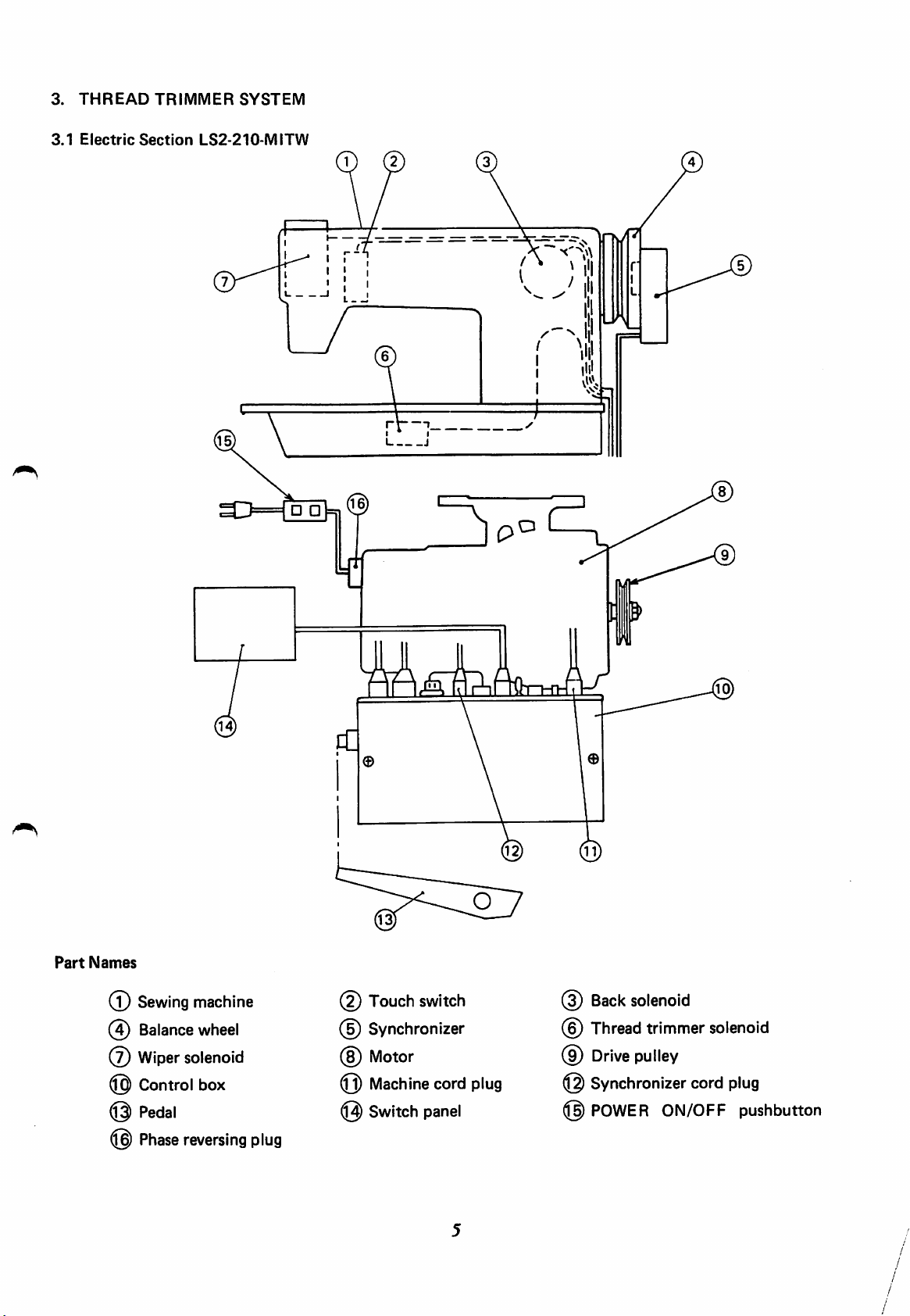
3.
3.1
THREAD
Electric
TRIMMER
Section
SYSTEM
LS2-210-MITW
Part
Names
Back
(T)
@
(7)
@
@
@
Sewing
Balance
Wiper
solenoid
Control
Pedal
Phase
reversing
machine
wheel
box
plug
(?)
Touch
Synchronizer
(§)
Motor
(Q)
Machine
@
Switch
switch
cord
panel
plug
@
(9)
@
@
solenoid
Thread
Drive
trimmer
pulley
Synchronizer
POWER
solenoid
cord
ON/OFF
plug
pushbutton
Page 7
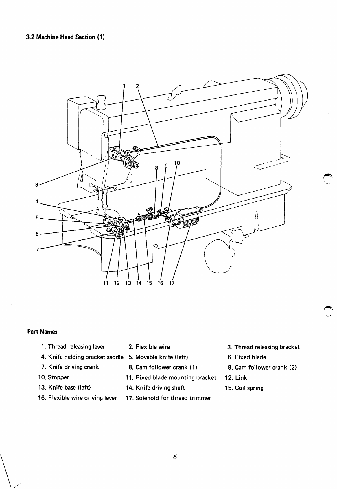
3.2
Machine
Head
Section
(1)
11
12 13 14
Part
Names
1.
Thread
4.
Knife
7. Knife driving
10.
Stopper
releasing lever 2.
helding
bracket
saddle
crank
Flexible
5.
Movable
8.
Cam
11. Fixed blade mounting bracket
13. Knife base (left) 14. Knife driving
16. Flexible wire driving lever 17.
Solenoid
15 16
wire
knife
follower
for
17
(left)
crank
shaft
thread
(1)
trimmer
3.
6.
9.
12.
15.
Thread
Fixed
Cam
Link
Coil
releasing
blade
follower
spring
bracket
crank
(2)
Page 8

3.2
Machine
Head
Section
(2)
12
13
14
15 16
Part
Names
3.
1.
4. Coil
7.
10.
13.
16.
19.
22.
Cover
spring
Wiper
Switch
Arm
side
Bushing
Reverse
Spring
for
shaft
for
cover
sewing
holder
wiper
touch
mech
back
crank
2.
5.
8.
11.
14.
17.
20.
23.
Switch
Link
Wiper
Push
button
Plunger
Feed
regulator
Reverse
Solenoid
for
wiper
sewing
bracket
lever
cam
lever
Solenoid
6. Wiper
9.
Hinged
12.
Solenoid
15.
Link
18.
Spring
21.
Shaft
for
bracket
pin
for
retainer
for
reverse
wiper
touch
back
sewing
shaft
Page 9

4.
PREPARATIONS
4.1
InstallationofSewing
Face
Plate-*
Phase-reversing
LIMI-STOP
clutch
BEFORE
plug
motor
OPERATION
Machine
and
Motor
Balance
wheel
Synchronizer
POWER
Switch
panel
ON/OFF
switch
Control
box
Plugs
from
machine
Rubber
pad
Switch
,.-1-
CLUTCH
BRAKE
panel
Passing the Machine Cords
Round
holeintable
SPEED
NEEDLE
0
POSITION
Wiring between sewing machine
Note:
Beforepluggingorunplugging,besuretoturn
Pass two cables from
plugs
into
the
respective
and
control
the
sewing machine through the
plug
receptacles.
box
off
the POWER
8
round
ON/OFF
holeinthe
pushbutton.
table
and
connect
the two
Page 10

4.2 Adjustment of Machine
Stop
Position
After thread trimming iscompleted by
timing
However,
as
[Preparation]
mark
(B)
if the
described
1. Disconnect
2. Remove
below.
aligned
marks
the
are
the
synchronizer
with
the
misaligned
plug (12 pins) of cord, which comes
first
cover.
heeling
timing
more
3. Operate the sewing machine and stop itatthe
adjustment.
[Adjustment]
1. While
2. Perform
3. When
(B)
has
head.
holding
and (C).
the
been
stabilized.
the
stop
the
light shielding disc by
toe-down
position
and
has
heeling
been
operationsofpedal several
stabilized,
the pedal,the
mark
than 3
mm,
hand,
connect
sewing
©.
The
adjust the setting position of
out
machine
sewing
isbroughtto a stop with the
machineisfully
of the machine head, from
factory-adjusted.
light
needle UP position. In this state, make
turn
the
the
balance
plug
wheeltomatch
timestocheckifthe
(12
pins)
coming
outofthe
the
shielding
the
controller.
the
following
timing
stop
disc
marks
position
machine
Sencond
First
timing
timing
mark
mark
Light
shielding
disc
Page 11

5.
ADJUSTMENTS
5.1
Thread
5.1.1
5.1.2
Trimmer
Construction
Cautionsonadjustment
Fixed
Thread
Mechanism
blade
bracket
guide
Fixed
blade
Movable
knife
Knife
unit
(left)
driving
crank
^
Knife
Knife
base
driving
Cam
Cam
Thread
unit
shaft
follower
follower
Fig. 1
trimmer
crank
crank
\
(1)
(1)
Cam
cam
follower
crank
Thread
(2)
.s
Stopper
trimmer
e.
Thread
solenoid
Flexible
trimmer
wire
solenoid
unit
A hook shaft cam system is utilized for
sewing machine, if
the
sewing
machine
operating state (the roller of cam follower crank (2) is engaged with
the
thread trimmer drive. Therefore, during
is
rotated
one
turn
with
the
thread
the
thread trimmer cam),
trimmer
the
adjustment
solenoidinthe
the
movable
knife makes contact with the needle, resulting in damage. Besure to bring the solenoid into the operating
state only during a normal thread trimming cycle (Needle
5.1.3
Installation
5.1.3.1
Knife
(1) As shown in Fig. 2, fit
hook
shaft
5.1.3.2
Fixed
(1) As shown In Fig. 3, install
unit
with
then
fix
of
base
unit
bushing (left)
blade
bracket
the
hook
with
the
knife
screws
base
and
the
knife base
and
unit
the
positioner
@ .
fixed
blade
unittothe
fix
with
the
fixed blade
dismounted,
bracket
screws
bracket
and
DOWN
unit
position to UP position).
Knife
base
unit
Hook
Fig. 2
r
shaft
bushing
(left)
of
Fig. 3
10
Fixed
blade
bracket
unit
Page 12

5.1.3.3
(1) Fig. 4 shows
(2) If the dimension indicated in
Relation
between
the
standard
three-thread breakage
fixed
blade
and
movable
state.
Fig.
4 is too
will
occur, leading to needle
thread cast-off, etc. after the thread trimming.
Reversely, if
the
dimension is
too
small, thread
trimming error may result. Therefore, caution must
be
exercised.
knife
large,
(left)
(Knife
edge
edge)
0.3
mm
Movable
/
knife
(left)
(3) Make the adjustment in (2) in
procedure
installation
of
fixed
blade
procedureoffixed
bracket
blade.
the
unit
installation
or
in
the
5.1.4 Connection of knife base and knife drivingcrank
(1) Make connection as shown in
use care for
sewing
5.1.5
Knife driving
machine
Knife
driving
the
position of link depends on
model.
shaft
and
crank
related
Fig.
5. At this time,
parts
Coil
Cam
spring
the
follower
irer
crc
crank
Fixed
(1)
n
Cam
blade
follower
a
crank
Fig. 4
Link
Fig. 5
(2)
\
Bushing
Knife
driving
shaft
Stopper
30.5
mm
Fig. 6
(1) Fig. 6 shows
the
standard setting position.
(2) Duringassembling, be sure to passthe knife driving shaft through the knife drivingcrank first.
(3) Fix
(4)
Fix
axial
the
cam follower
the
stopper
direction.
to
the
crank
recess so
(1)tothe
that
the
recessofknife driving
knife
driving
shaft
11
shaftatthe
can
rotate
position
smoothly
shown
without
playinthe
in Fig. 6.
Page 13

5.1.6
Installationofthread
trimmer
solenoid
unit
(1) Operation stroke of thread trimmer solenoid
®
Standard
@
Adjust
(2)
Installationofunit
(T)
Install
Fig. 7.
©
Install
provided between
crank
the
operation
strokeis3.7
the operation stroke by
the unit
with
the
the unit so that
the
driving lever and cam follower
(2)
with
the stopper nut @incontact
solenoid.
mm.
use
screws
(§)
and©shown
approximately
of the nut
3.7
mm
Thread
trimmer
®.
Cam
follower
Driving
crank
lever
(2)
solenoid
1
mm
/
(R
Solenoid
mounting
bracket
in
1
mm
is
with
@
5.1.7
Installation
(1)
Align
matching
(2)
Set
turn
the
(3) When
and
clearance
Thread
When
the
solenoidisenergized
clearanceof0.5
follower
is
by moving
arrow
the
the
cranks
standard
the
direction
of
second
diread
markonthe
the
the
cam
the
thread
makes
the
cam
trimmer
trimmer
thread
contact
operationofthread
follower
between
cam
mmisprovided
(1)
and
(2) as
installation
solenoid
in Fig. 7.
trimmer
timing
mark
arm.
solenoidtothe
trimmer
with
cam
the
crank
the
cam
and
underthiscondition,
between
shown
status.
mounting
cam
in Fig. 8.
Make
bracket
@ on the
operation
forward.
roller,
trimmer
(2)
roller
At
fix
the
solenoid has been reset
has
returned,
endis0.5
Thread
Roller
the
cam
This
adjustment
in
the
pulley
the
point
cam.
the
to
trimmer
with
state
where
standard
1.0
mm.
cam.
the
and
0.5
mm
Matching
Fig. 8
mark
0.5to1.0
mm
Fig. 9
12
Page 14

Note: The standard positionofcam follower crank (2) prior
to the operation is shown in Fig. 10. When this
position has been changed, for example, by removing
the stopper plate, make adjustment with die adjust
screw (Fig. 6)
5.1.8
Adjustment of knife engagement
(1) Positions of movable knife (left)
(T)
Fig.
11
shows
to
zero.
the
and
then
standard
make
and
state,
adjustment
fixed blade
with
the
in (1) to (3).
feed
dial
Movable
set
knife
(left)
2
mm.
Fig.
10
32
9
mm
mm
3.3
32
Fixed
m
mm
blade
(2)
Adjustment
(J) Set the
sewing
by
has moved
amount
Make
(3)
Adjustmentofknife
(3)
The
movable knife (left)
with
@
When
thread,
producesaneffect.
machine.
the
thread
adjustmentbythe
standard
each
cutting action is poor
of knife engagement
solenoid
is 1.5to2.0
trimmer
to
the
to the
Then,
operation
the
cam.
maximum,
mm. See Fig. 12.
installationofknife driving
engagement
knife
engaging
and
fixed blade
otheratthe
a
slight
position
increase
amount
state
and
movable
When
pressure
knife
(left) is
the
movable
the
standard engagement
pressureisobtained
start
making
shown
especially
of
the
in Fig.
because
engagement
rotate
rotated
knife (left)
when
contact
13.
of thick
pressure
the
crank.
the
Knife
Movable
Movable
driving
1.0to2.0mm
knife
knife
deft)
(left)
crank
Fig. 11
Fig.
12
Fixed
blade
3
mm
@ To
in
adjust
the
Fig.11and
engagement
adjust
withthe adjust
pressure,
loosen
screw
the
(§).
lock
13
nut(§)
Fixed
blade
Fig.
13
Page 15

5.1.9 Adjustment of needle
(1)
Make
adjustment so that when the thread trimmer solenoid is
thriad
tension releasingamount
operated, the tension discs of thread tension regulator open
approximately1mm.
(2)Tomake
wire.
CAUTION
adjustment,
loosen
the nuts(§)and
move
If the opening of tension discs is too small, the needle
thread will be trimmedatshort
thread cast-off. Reversely, if
too
large,
the tension discs are left opened continuously,
leadingtoloose stitches.
5.2
AdjustmentofNeedle
(1) Adjust
pretension
Clockwise
wise
turn
the
remaining length
adjust
turn
increases
Thread
nut @.
reduces
the
length.
the
length, leadingtoneedle
the
opening of tension discs is
Remaining Length
of
needle
remaining length.
thread
by use
Counterclock
the
flexible
of
the
o
Flexible
wire
Fig.
14
Fig.
15
5.3
Cautions
Adjust
that
twisted,
smoothly
mounting
5.4
When
canbeadjusted
the
positionofsolenoid in
the
plungerofsolenoid
and
in
screws.
Touch-Back
the
screw
on
installation
make
the
See
Pushbutton
vertically.
sure
vertical
Fig.
@
is
of
Touch-Back
and
that
the
direction.
16.
loosened,
Solenoid
the
longitudinal
the
link
(for
connection)
reverse sewing lever moves
After
the
position
direction
that,
tighten
of pushbutton
are
so
not
the
Fig.
Feed
16
regulating
Push
Solenoid
lever
button
14
Fig.
17
Page 16

5.5
Wiper
5.5.1 Height of wiper
(1)
The standard height of wiper is 2 mm belowthe tip of needle
which is stopped at
(2)
Make
adjustment
5.5.2
Wiper
operation
the
after
position
UP position.
loosening
the
screw
@.
(1) The standard operation position of wiper is 0 to 2 mm from
the center of needle when the plunger of wiper solenoid is
fully pushed (when the solenoid is energized).
(2)
To
make
adjust
adjustment,
the
mounting
loosen
positionofsolenoid
the
screws
(B)
unit.
and ©
and
then
•Wiper
Wiper
solenoid
unit
plunger
5.6 Adjustment of Forward and ReverseStitch Lengths
Loosen
shaft
decreases
the
(B).
the
screw
Clockwise
@
and
make
turn
reverse stitch length.
adjustmentbyturning
increase
the
forward
stitch
the
eccentric
length
and
Counterclockwise turn decreases the forward stitch length and
increases
5.7
the
reverse stitch length.
AdjustmentofFeed Dog Inclination
0to2
mm
Fig.
Fig.
18
19
UJ
CJ
To
adjust
turn the eccentric pin (B), Clockwise turn setstodownward tilt.
Counterclockwise
the
inclination
of
feed
turn
setstoupward tilt.
dog,
loosen
the
screw
15
@ and
Fig.
20
Page 17

5.8
TimingofFeed
(1) The position for
the
standard feed timing is where the needle
tip is approximately 0 to 3 mm from the upper surface of
needle plate when
wheel
surfaceofneedle
and
the
the
feed dog is risen by turning
teethoffeed
plate.
dog
become
flush
with
the
balance
the
upper
(2) Make adjustment by the mounting positions of feed lifting
cam
feed
cam.
1)
Installationoffeed
Mount the feed lifting cam so that the first screw
feed lifting cam is located just at
the
timing
lower
wheelinthe
2)
Installationoffeed
Mount
camislocated
rising
turning
mark
endofneedle
forward
the
feed
needle
the
balance
@ of
cam
justatthe
has
reached
lifting
cam
rising
bar
direction.
cam
needle
supporter
so that the third
side
the
top
wheelinthe
forward
the
side position when
bar
has
reached
by
turning
screw
position
surfaceofneedle
the
@ of
when
direction.
the
plate
(B)
the
balance
Needle
feed
tip
of
of
by
bar
supporter
\
• Needle bar
Fig. 21
Feed
Fig.
^—
22
cam
0to3
Feed
mm
lifting
f
cam
Needle
Needle
plate
Fig.
Feed
23
cam
Feed
lifting
cam
16
Page 18

5.9 Relation between Needle and Feed Dog
(Make
(1)
Set
(2) Remove
correctionsothatthe
the stitch length dial to 0.
the
face plate.
needle
drops
tothe
needle
hole
centeroffeed
dog.)
©
(3) Tilt
(4)
(5)
(6) Loosen the set screw (B) of needle feed rod crank (left) and
the
machine head toward the opposite side.
Loosen
rear surfaceofbed
regulator
At
the
regulator
make
of
the set
crank.
this
time,
figure between
crank.
adjustment
needle
plate.
screw
make
so
@ of
and
sure
the
that
needle
make
adjustmentasshowninthe
that
thereisclearanceasshown
needle feed driving
the
needleislocated
feed
driving
crank
crank
at
at the
and feed
the
center
feed
in
Socket
Needle
driving
bolt
Socket
Needle feed driving
bolt
crank
C
Needle
driving
feed
crank
Fig.
24
feed/
crank adjustingcrank
mm
Stitch
length
12
mm
mm
132mm
Needle
I
c7anV(ieft)
Cp
Needle
for
feed
(7)
Loosen
make
is aligned with
the
screw©of
adjustmentsothat
the
needle.
feed
the
rock
needle
shaft
crank
hole
centeroffeed
17
'
(left)
32
and
dog
feed
Fig.
hole
dog
Fig.
26
Feed
27
rock
crank
shaft
(left)
Page 19

5.10
Adjustment
of Needle Feed
Amount
When
uneven
material
feeding
occurs depending on fabrics, adjust the eccentric set pin of needle feed
driving crank to increase the needle feed amount.
(1)
Set
the
feed regulating dialto0.
(2)
Loosen
the eccentric set pin
When
needle
the
feed
the
screw
mark
amount
@ and then
(B).
©islocated
is
the
on the
same
make
adjustment by turning
feed
as
the
feed
dog.
When
the
mark
rock
of
the
(3) When
center
remove
rod
dropstothe
shaft,
feed
the
of
the
crank
the
amount
above
feed
face
(left),
needle
dog
©islocated
needle feed
of feed dog).
adjustment
is misaligned
plate,
and
hole
on the opposite
amountisthe
has
been
with
loosen
make
centeroffeed
the
adjustment
made,
the
screw
dog.
rock
shaft
amount
side
maximum
the
needle.
® of
so
that
side,
of
feed
to the
needle
feed
{110%
Therefore,
needle
the
needle
the
hole
feed
Feed
Needle
shaft
0
rockshaft
feed
rock
crank
(left)
Fig.
Needle
28
feed
driving
crank
(4) While
to
the
contact
balance
the
feed
maximum
with
wheel.
motion
value,
the
needle hole
is performed with
checkifthe
of
feed
needle
dog
the
does
by
feed dial
not
turning
18
set
make
the
o
Fig.
29
o
Page 20

5.11
Hook,
Bobbin
Case,
and
Bobbin
(1) Use
guide
(2) Use
@ at the
(3)
For
the
possible.
the
undertrimmer
slit @ as
the
bobbin case which has idle running prevention spring
showninFig.
bottomasshowninFig.
the
bobbin,
deformation
use
of
hook
the
attached
bobbin,
which
has
the
bobbin
30.
31.
bobbin.Inordertoprevent
wind
the
thread
as lightly as
thread
Fig.
Fig. 31
30
19
Page 21

6.
TROUBLESHOOTING
Thread
med.
Neeedle
outofthe
start
of stitching.
Trouble
cannot
thread
needle
be
trim
comes
at
Knife
Knife engaging
Damage
of
Machine
Machine
Positionoffixed
Since
operated
cannot
At
thread
the
open.
Cause
engagementisimproper.
pressureistoo
and/or
movable
knife
stops
stop
wearofcutting
(left),
too
early.
position
blade is
the
the
movable
too
be
performed
time
tension
early,
of
thread
regulator
knife
loop
low.
edge
fixed
blade
varies largely.
improper.
(left)
spreading
by
the
knife.
trimming,
discsdonot
Adjust
Adjust
Change
Adjust
Check
timeofthread
Adjust
is
Adjust
trimmer
Adjust
releasing.
Corrective
the
engagement
the
engaging
the
knife
the
stop
position.
needle
thread
trimming.
the
positionoffixed
the
installation
cam.
the
needle
Action
pressure.
and/or
tension
thread
amount.
of
tension
blade.
at
the
blade.
thread
Reference
Section
5.1.8
•
5.1.8
4.2
5.1.9
5.1.3
5.1.7
5.1.9
Skip
stitchatthe
stitching
Needle
after
threadistoo
thread
trimming.
start
Thread
trimmer
Threadistrimmedbythe
before
knife
blade.
the
(left) engage
Needle is
the
thread.
Pretension is
of
long
Bobbin
the
thread
Tension
strong.
The
thread
after
Pretensionistoo
Thread
Thread
and
smooth.
thread
Idle
trimming.
remaining
on
thread
trimmer
movement
the
cutting
too
too
running
of
bobbin
the
needle
trimming.
hook
timing is
edgeofmovable
with
thick
with
strong.
becomes
of
length
weak.
short
bobbin
thread
sideistoo
timingistoo
between
positioner
too
fixed
the
respect
of
the
early.
blade
fixed
due
at
Is
needle
short
late.
hook
is
to
to
the
too
not
Adjust
trimmer
Adjust
Adjust
the
Use a
bobbin
prevention
Adjust
the
1.
Adjust
2.
Check
trimmer
3.
Check
Adjust
the
Adjust
trimmer
the
installation
cam.
the
position
pretension.
case
with
spring.
tensionofbobbin
the
pretension.
the
installation
cam.
the
thread
pretension.
the
installation
cam.
of
contact
of
fixed
idle
of
of
thread
blade.
running
thread.
thread
area.
thread
5.1.7
5.1.3
5.2
5.9
5.2
5.1.7
5.2
5.1.7
20
Page 22

A
MITSUBISHI
HEAD
OFFICEiMITSUBISKI
NAGOYA
ELECTRIC
WORKS
DENKIBLDG
MARUNOUCKI
: 1
-14.YADA-MINAMI
CORPORATION
TOKYO
100TELEX:
J24532
CABLE
S .
HIGASHI-KU.NAGOYA.JAPAN
MELCOTOKYO
3602(REC)
 Loading...