

Page 1
MITSUBISHI
Industrial
TECHNICAL
Automatic
Model
LS2-180
Sewing
INFORMATICN
Undertrimmer,
Machine
Single-Needle
Lockstitch
'A
ET-0S2
MITSUBISHI
ELECTRIC
Page 2
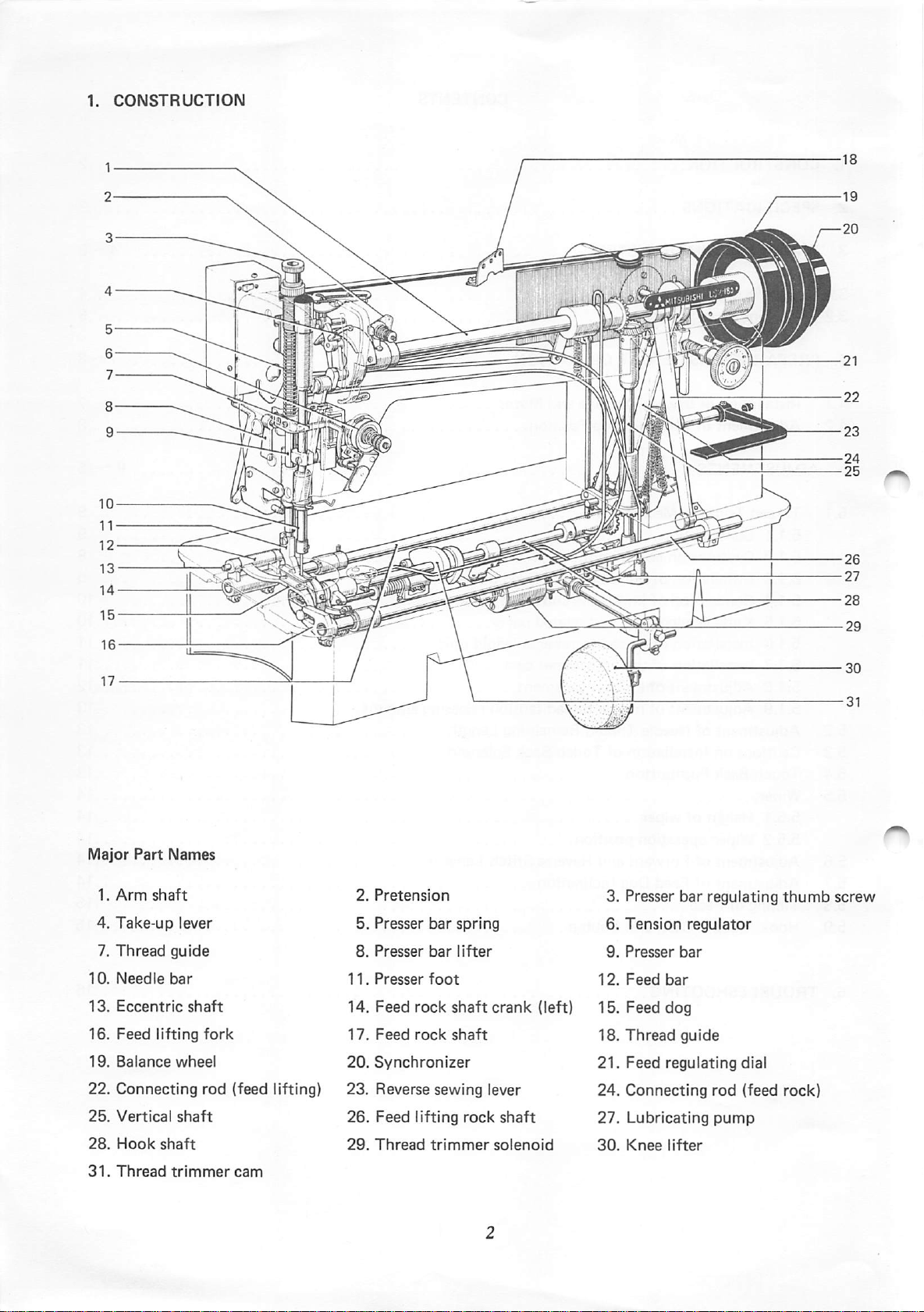
1.
CONSTRUCTION
2.
SPECIFICATIONS
3.
THREAD
TRIMMER
SYSTEM
CONTENTS
2
3
4~6
3.1
3.2
4.
4.1
4.2
^
5.
Electric
Machine
PREPARATIONS
Section
Head
InstallationofSewing
AdjustmentofMachine
ADJUSTMENTS
5.1
Thread
5.1.1
5.1.2
5.1.3
5.1.4
5.1.5
5.1.6
5.1.7Installation
5.1.8
5.1.9
5.2
AdjustmentofNeedle
5.3
5.4
5.5
Cautions
Touch-Back
Wiper
Trimmer
Construction
Cautions on
Installation
Connectionofknife
Knife driving
Installation
Adjustmentofknife engagement 12
Adjustmentofneedle
on
Installation
Pushbutton
Section
BEFORE
Mechanism
adjustment
of
shaft
of
of
OPERATION
Machine
Stop
knife
and
thread
thread
Thread
of
and
Motor
Position
base
and
fixed
blade
base
and
knife driving
bracket
crank
unit
related parts 10
trimmer
trimmer
thread
solenoid
cam
tension
unit
releasing
amount
Remaining Length 13
Touch-Back
Solenoid
4
5
7-8
7
8
9-15
9
9
9
9
10
11
11
13
13
13
14
5.5.1 Heightofwiper 14
5.5.2
Wiper operation position 14
5.6
Adjustment
of Forward and Reverse
Stitch
Lengths 14
5.7 Adjustment of Feed Dog Inclination 14
5.8 Timing of Feed 15
5.9
Hook, Bobbin Case,
and
Bobbin
15
6.
TROUBLESHOOTING
16
Page 3
x.itsuajii!
Major
Part
Names
1.
Arm
4.
Take-up
Thread
7.
10.
Needle
13.
Eccentric
16.
Feed
19.
Balance
22.
Connecting
25.
Vertical
28.
Hook
31.
Thread
shaft
guide
bar
lifting
wheel
shaft
shaft
trimmer
lever
shaft
fork
rod (feed lifting)
cam
2.
Pretension
5. Presser
8.
Presser
11.
Presser
14.
Feed
17.
Feed
20.
Synchronizer
23.
Reverse
26.
Feed
29.
Thread
bar
bar
foot
rock
rock
sewing
lifting
trimmer
spring
lifter
shaft
shaft
rock
crank
lever
shaft
solenoid
(left)
3. Presser bar regulating
6.
Tension
9.
Presser
12.
Feed
15.
Feed
18.
Thread
21.
Feed
24.
Connecting
27.
Lubricating
30.
Knee
regulator
bar
bar
dog
guide
regulating
rod
pump
lifter
thumb
dial
(feed rock)
screw
Page 4
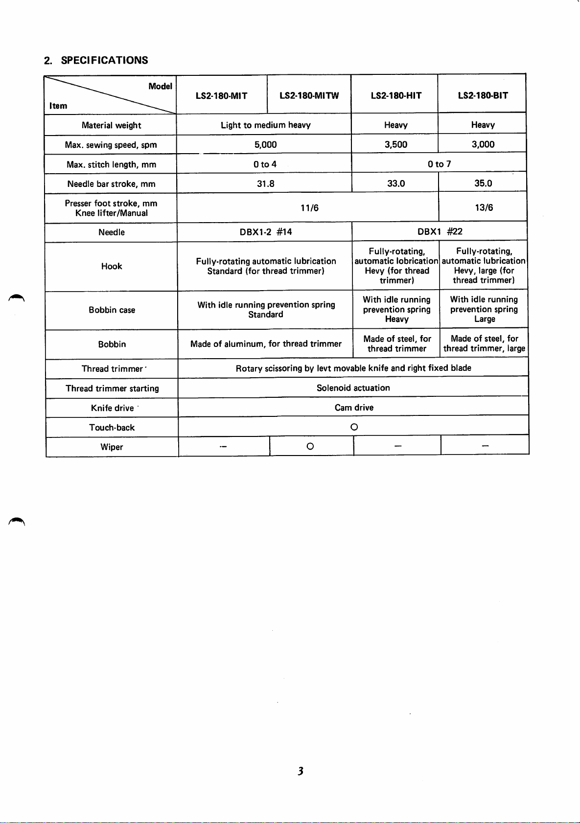
2.
SPECIFICATIONS
Item
Material
Max.
Max,
Needle
Presser
Knee
Thread
sewing
stitch
bar
stroke,
foot
lifter/Manual
Needle
Hook
Bobbin
Bobbin
trimmer'
weight
speed,
length,
stroke,
case
—
spm
mm
mm
mm
Model
LS2-180-MIT
Lighttomedium
5,000
0to4
DBX1-2
Fully-rotating
Standard
With idle
automatic
(for
running
Standard
Madeofaluminum,
Rotary scissoring by levt movable knife and right fixed blade
31.8
#14
thread
prevention
for
LS2-180-MITW
heavy
11/6
lubrication
trimmer)
spring
thread
trimmer
LS2-180-HIT
Heavy
3,500
33.0
Fully-rotating,
automatic
Hevy
(for
trimmer)
With
idle
prevention
Heavy
Madeofsteel,
thread
DBX1
lobrication
thread
running
spring
trimmer
for
0to7
#22
automatic
thread
LS2-180-BIT
Heavy
3,000
35.0
13/6
Fully-rotating,
Hevy, large
lubrication
thread
trimmer)
With
idle
running
prevention
Large
Madeofsteel,
trimmer,
(for
spring
for
large
Thread
trimmer
Knife
drive
Touch-back
Wiper
starting
Solenoid
~
O
Cam
actuation
drive
O
—
—
Page 5
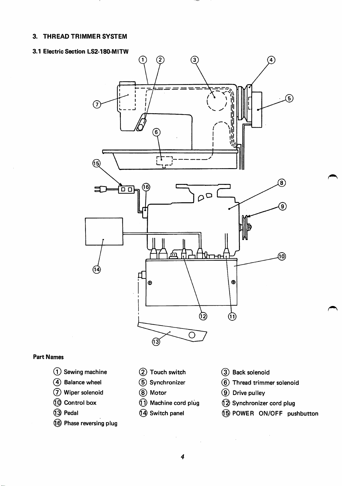
3.
3.1
THREAD
Electric
TRIMMER
Section
SYSTEM
LS2-180-MITW
V
Part
Names
(T)
(4)
@
@
©
®
Sewing
Balance
Wiper
Control
Pedal
Phase
machine
wheel
solenoid
box
reversing
plug
(2)
Touch
(5) Synchronizer
(8)
Motor
0)
Machine
@
Switch
switch
cord
panel
plug
@
Back
(§)
Thread
(9)
Drive
@
Synchronizer
@
POWER
solenoid
trimmer
pulley
ON/OFF
solenoid
cord
plug
pushbutton
Page 6
^0^
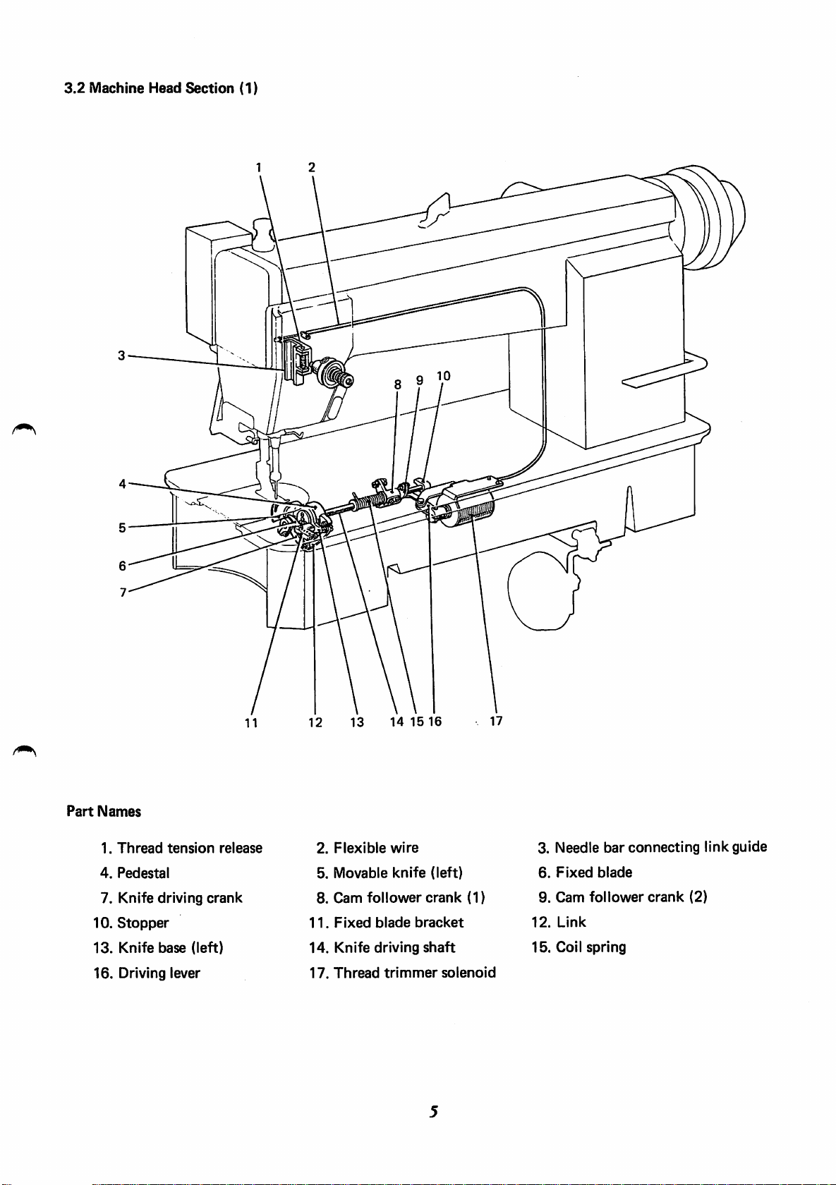
3.2
Machine
Head
Section
(1)
Part
Names
1.
Thread
4.
Pedestal
7. Knife
10.
Stopper
13.
Knife
16.
Driving lever
tension
driving
base
crank
(left)
release
2.
5.
8.
11.
14.
17.
Flexible
Movable
Cam
follower
Fixed
Knife
Thread
14 15
wire
knife
blade
driving
trimmer
16
(left)
crank
bracket
shaft
solenoid
(1)
3. Needle
6.
Fixed
9.
Cam
12.
Link
15.
Coil
bar
blade
follower
spring
connecting
crank
(2)
link
guide
Page 7

3.2
Machine
Head
Section
(2)
12
13 14 15
16
Part
Names
1.
4. Coil
7.
10.
13.
16.
19.
22.
Cover
spring
Pin
Micro
Side
cover
Bushing
Reverse
Spring
switch
sewing
bracket
crank
9
10
11
3.
2.
5.
8.
11.
14.
17.
20.
23.
Switch
Link
Wiper
Pushbutton
Plunger
Feed
regulator
Reverse
Solenoid
sewing
mounting
cam
lever
bracket
6.
9.
12.
15.
18.
21.
Wiper
Switch
solenoid
Wiper
Spring
bracket
bracket
Back
solenoid
Link
bracket
For
reverse sewing
Page 8
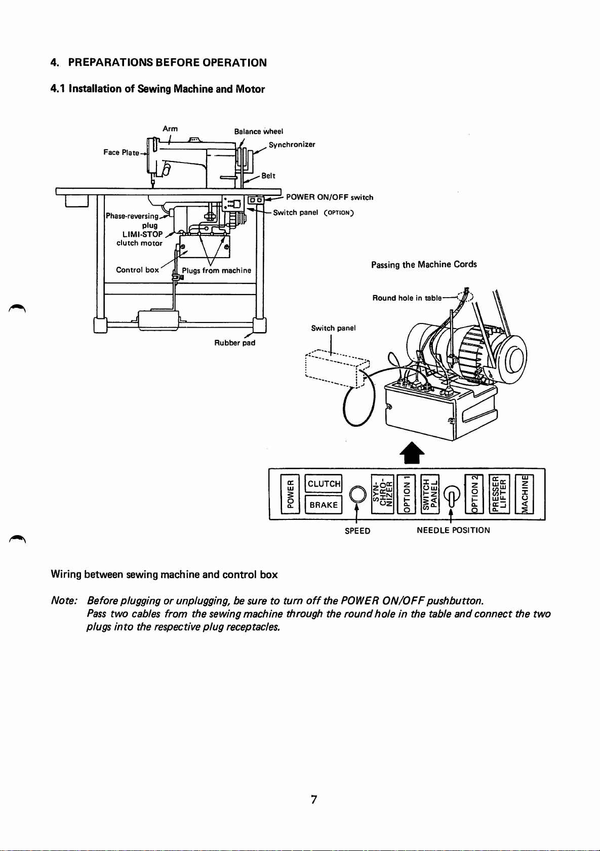
4.
PREPARATIONS
BEFORE
OPERATION
4.1 InstallationofSewing Machine
Arm
-4
Face
Plate-
Phase-reversing
LI
clutch
Control
plug
MI-STOP
motor
box
Plugs
from
and
machine
Rubber
Motor
Balance
/
pad
wheel
Synchronizer
-Belt
POWER
Switch
panel
ON/OFF
Switch
Coition)
panel
switch
Passing
Round
the
Machine Cords
0
Wiring
Note:
between
sewing
machine
and
control
Beforepluggingorunplugging, be
Pass
two
plugs
cables
into
the
respective
from
the
sewing
plug
receptacles.
box
suretoturn
machine
through
GC
CLUTCH
UJ
§
o
BRAKE
o.
oz
Uuj
££
W}-
LU
U.
-4-
off
the
the
SPEED
POWER
round
NEEDLE
ON/OFF
holeinthe
POSITION
pushbutton.
table
and
connect
the
two
Page 9

4.2
AdjustmentofMachine
After
thread
timing
However, if
as
described
trimmingiscompleted
mark
(B)
aligned
the
marks are misaligned more than 3 mm, adjust
below.
[Preparation]
1.
Disconnect
2.
Remove
3.
Operate
adjustment.
the
the
[Adjustment]
Stop
with
the
plug
(12
synchronizer
sewing
machine
Position
by heeling
the
first
timing
pins)ofcord,
cover.
and
stopitat
the
pedal,
mark
which
the
the
sewing
©.
The
comes
needle UP position. In
outofthe
machineisbroughttoa
sewing
the
machineisfully
setting position of light shielding disc
machine
this
head,
state,
stop
with
factory-adjusted.
from
the
controller.
make
the
following
the
1. While
®
and
2. Perform
has
been
3. When
head.
holding
©.
the
stabilized.
the
stop
Sencond
the
light shielding disc by
toe-down
position
timing
and
has been stabilized,
mark
heeling
hand,
turn
the
balance wheeltomatch
the
operationsofpedal several timestocheckifthe
connect
the
plug
(12
pins)
coming
Light
shielding
outofthe
timing
stop
disc
marks
position
machine
1^
First
timing
mark
i
8
Screw
A
Page 10

5.
ADJUSTMENTS
5.1
Thread
5.1.1
5.1.2
A
hook
sewing
operating
knife
state
Trimmer
Construction
Cautionsonadjustment
shaft
cam
machine,
state
makes
only
contact
during a normal
Mechanism
Fixed
blade
bracket
Thread
guide
Fixed
blade^
Movable
Knife
systemisutilized
if
the
sewing
(the
rollerofcam
with
the
thread
unit
Thread
knife
(left)
driving
crank
for
machineisrotated
follower
needle,
resultingindamage.Besuretobring
Knife
Knife
the
crank
driving
Cam
thread
trimmer
base
unit
shaft
follower
Fig. 1
trimmer
one
(2) is engaged
crank
turn
Cam
cam
(1)
follower
drive.
with
with
crank
Therefore,
the
thread
the
thread
the
trimming cycle (Needle DOWN positiontoUP position).
Thread
(2)
trimmer
solenoid
trimmer
I
Thread
Stopper
during
trimmer
solenoid
Flexiblewire
trimmer
the
adjustment
solenoid
solenoidinthe
cam),
the
into
the
operating
unit
of
movable
5.1.3
5.1.3.1
(1) As
hook
®.
5.1.3.2
(1) As
unit
then
Installation
Knife
shown
shaft
Fixed
shown
with
fix
with
of
knife
base
base
unit
in Fig. 2,
fit
bushing (left)
blade
bracket
in Fig.3,install
the
hook
positioner
the
screws
and
the
knife base
and
unit
the
® .
fixed
blade
fix
with
fixed
blade
dismounted,
bracket
unittothe
the
screws
bracket
and
unit
Knife
Fig. 2
base
unit
Hook
Fixed
shaft
blade
bushing
bracket
(left)
unit
Fig. 3
Page 11

5.1.3.3 Relation between fixed blade and movable knife (left) edge
(1) Fig. 4
(2) If
shows
the
dimension
three-thread
thread
Reversely, if
trimming
be
cast-off,
error
exercised.
the
standard
indicated
breakage will
etc.
after
the
dimension
may
result.
state.
in Fig. 4 is
occur,
the
is
too
Therefore,
too
large,
leadingtoneedle
thread
trimming.
small,
caution
thread
must
(Knife
edge)
0.3
mm
Movable
/
knife
(left)
(3) Make
procedure
installation
5.1.4
the
adjustment
of
fixed
procedureoffixed
in (2) in
blade
bracket
blade.
the
unit
installation
or
in
the
Connectionofknife base and knife driving crank
(1) Make connection as shown in Fig. 5. At this time,
use care
sewing
5.1.5
Knife driving
for
machine
Knife
the
model.
shaft
driving
position
and
crank
of
link
related
depends
parts
Bushing
Coil
(BIT:
Cam
90.5
on
spring
87.5
follower
mm
mm)
Fixed
the
crank
\ Car
(1)
^
© ©:
blade
LS2-180-MIT
LS2-180-HIT
©
©
Cam
follower
n4
Knife
driving
I—I
o
r'
B
Link
&
crank
shaft
jn
Fig. 4
(2)
Stopper
Fig. 5
©
r
Adjust
LS2-180-BIT
Link
0
m
screw
Fig. 6
(1) Fig. 6 shows
(2)
During
(3) Fix the cam follower crank (1) to the
the
standard setting position.
assembling,
besureto
pass
the
knife
recess
driving
of knife
shaft
through
driving
the
knife
shaft at the position shown in
(4) Fix the stopper to the recess so that the knife driving shaft can rotate smoothly without play in the
axial
direction.
10
driving
crank
first.
Fig.
6.
Page 12

5.1.6
Installation
(1)
Operation
®
Standard
(5)
Adjust
(2)
Installationofunit
of
thread
trimmer
strokeofthread
operation
the
operation
strokeis3.7
trimmer
stroke
solenoid
solenoid
mm.
by
use
unit
of the nut @.
Cam
Driving
follower
crank
lever
(2)
3.7
mm
Thread
trimmer
solenoid
Solenoid
mounting
bracket
1
mm
(l)
5.1.7
(1)
(2)
Install
Fig. 7.
Install
the unit with the
the
provided between
crank
the
When
(2)
solenoid.
the
with
solenoid is energized
clearanceof0.5
follower
is
the
cranks
standard
by moving
arrow
direction
Installationofthread
Align
matching
Set
turn
the
the
the
the
cam
second
markonthe
thread
thread
makes
unit
screws
so
that
the
driving lever and cam follower
the
stopper
(B)
and
approximately
nut @ incontact
under
this
mm is provided between
(1)
and
(2) as
shown
installation
the
solenoid mounting bracket in the
in Fig. 7.
trimmer
timing
mark
status.
cam
® on the
in Fig. 8.
Make
adjustment
arm.
trimmer
trimmer
contact
solenoid
cam
with
the
to
the
forward.
roller,
operation
At
fix
the
shown
1 mm is
with
condition,
the
cam
This
pulley
state
the
point
cam.
in
with
the
and
where
0.5
mm
Matching
Fig. 8
mark
(3) When the operation of thread trimmer solenoid has been reset
and
the
cam
clearance
Thread
between
trimmer
follower
cam
the
crank
cam
and
(2)
has
returned,
roller
endis0.5to1.0
Thread
Roller
the
trimmer
Fig. 9
11
standard
mm.
cam.
0.5to1.0
•
mm
Page 13

Note:
The
to
position
the
screw
5.1.8
(1)
Adjustmentofknife
Positionsofmovable
(J)
Fig.11shows
standard
the
operation
has
stopper
(Fig. 6)
positionofcam
is
been
changed,
plate,
the
make
and
then
engagement
knife
(left)
standard
shown
adjustment
make
and
state.
follower
in Fig. 10. When this
for
example,
adjustment
fixed
blade
crank
by
removing
with
the
in (1) to (3).
(2)
adjust
prior
Cam
Movable
/'
I'Q
t./
follower,
crank
(2)
knife (left) (BIT:
LS2-180-BIT
2
mm
^ Hook
shaft
,
/Roller
.^nife
driving
\^7.5
'
J\J
/
9
mm
mm)
Fig.
10
f2.5mity'
i-
•
LS2-1
LS2-180-HIT
Fixed
/ ®
/ /
2
mm.
blade
BO-MIT
/
>^
i
Sii
(2)
Adjustmentofknife
® Set the
sewing machine.
by
has moved
amount
(5)
Make
(3)
Adjustmentofknife engagement pressure
® The
movable knife (left)
with
(2)
When
solenoid
the
thread
is 1.5to2.0
adjustment by the installation of
standard
each
otheratthe
cutting
engagement
to the
Then,
trimmer
to
the
knife
cam.
maximum,
mm. See Fig. 12.
engaging
and
position
actionispoor
operation
the
movable
fixed blade
thread, a slight increase of
producesaneffect.
amount
state and
knife
(left) is
When
the
movable
the
standard
knife
driving
pressureisobtained
start
making
shown
especially
in Fig.
13.
becauseofthick
the
engagement pressure
rotate
knife
engagement
the
rotated
(left)
crank.
when
the
contact
Knife
Movable
knife
Movable
driving
1.5to2,0
knife
deft)
(left)
crank
Fig. 11
mm
Fig.
12
Fixed
blade
3
mm
@
To
adjust
in
Fig.11and
the
engagement
adjust
with
pressure,
the
adjust
loosen
screw
the
@.
lock
J2
nut
(J)
Fixed
blade
Fig.
13
Page 14

5.1.9
Adjustmentofneedle
thread
tension
releasing
amount
Thread
trimmer
solenoid
(1) Make
(2)Tomake
CAUTION
5.2
(1)
adjustmentsothat
operated,
approximately1mm.
the
tension
adjustment,
wire.
If
the
opening
thread
thread
too
leadingtoloose
will be
cast-off. Reversely, if
large,
of
trimmedatshort
the
tension discs are left opened continuously,
stitches.
when
the
discsofthread
loosen
the
nuts®and
tension discs is
length, leadingtoneedle
the
openingoftension
thread
tension
too
AdjustmentofNeedle Thread Remaining Length
Adjust
pretension
Clockwise
wise
turn
the
remaining length of needle
adjust
turn
increases
nut@.
reduces
the
the
length.
remaining length.
trimmer
move
small,
thread
solenoid
regulator
the
the
needle
open
flexible
discs is
by use
of
Counterclock
the
is
.0
0
Flexible
wire
Fig.
14
5.3
Cautions
Adjust
that
the
twisted,
smoothly
mounting
5.4
Touch-Back
on
Installation
the
position of solenoid in
of
plungerofsolenoid and
and
make sure
in
the
screws.
vertical direction.
See
Pushbutton
Fig.
that
16.
Touch-Back
the
the
link (for connection) are
the
reverse sewing lever moves
Solenoid
longitudinal direction so
After
that,
tighten
The function of pushbutton can be eliminated as required.
(1) Normally,
Fig.
pushbutton
this
17.
When
is pressed, reverse
pushbutton
the
sewing
is
usedatthe
machine
is
operated
position
stitchingisperformed.
shown
after
not
the
in
the
Fig.
Fig.
15
Feed
16
regulating
Solenoid
lever
(2) When
the
it is
the
broken
pressed.
pushbutton
line in Fig.
is
movedtothe
17,
the
switch
does
position
not
function
indicated
even if
13
by
Fig.
17
Page 15

5.5
Wiper
5.5.1
(1)
(2) Make
5.5.2
(1)
(2)
Heightofwiper
The
standard
whichisstoppedatthe
adjustment
Wiper
operation
The
standard
the
fully
To
adjust
center
pushed
make
of
adjustment,
the
mounting
(when
heightofwiper
UP
after
loosening
position
operation positionofwiper is 0to2 mm
needle
when
the
solenoid is energized).
loosen
positionofsolenoid
is 2 mm
position.
the
the
plungerofwiper
the
screws
below
screw
the
tipofneedle
solenoid is
(B)
and © and then
unit.
from
DC
0to2
mm
Wiper
2
mm
solenoid
unit
plunger
5.6
AdjustmentofForward
(1)
Loosen
eccentric
length
wise
reverse
5.7
AdjustmentofFeed Dog Inclination
(1)
To adjust the
turn the
tilt. Counterclockwise
and
turn
stitch
the
screw
shaft
®.
increases
increases
length.
inclinationoffeed
eccentric
and
@
and
Clockwise
the
reverse
the
forward
pin
©.
turn
Reverse
make
Clockwise
setstoupward tilt.
adjustment
turn
stitch
stitch
dog,
Stitch
reduces
length.
length
loosen
turn setsto
Lengths
the
by
turning
forward
Counterclock
and
decreases
the
screw
downward
the
stitch
the
@ and
Fig.
Fig.
18
19
14
Fig.
20
Page 16

5.8
TimingofFeed
(1)
The
position
tipislocated
needle
and
the
needle plate.
plate
teeth
for
the
standard
approximately
when
the
feed
of
feed dog align with
See
Fig.
21.
feed
timingiswhere
3
mm
below
dogissunkbyturning
the
the
upper
top
the
needle
surface
the
of
pulley
surface of
Needle
plate
Feed
SJSjsjv.
dog
Needle
0
•sJ^sTNj^
V
^ •
3
mm
(2) Make
cam
adjustment
feed
cam.
by
the
1) Installationoffeed lifting cam
To
2)
5.9
Hook,
(1) Use
guide
install,
with
Installationoffeed
To
install,
to the
Fig.
21.
Bobbin
the
slit @ as
align
that of the
set the third
second
Case,
undertrimmer
showninFig.
the center of
second
screw
and
cam
® of
Bobbin
hook
mounting
oil
screw
screw
@ of
feed
which
22.
positionsoffeed lifting r
hole
© in the
© in the
feed
lifting
has
feed
cam
camasshown
the
lifting
with
bobbin
arm
respect
shaft
cam.
thread
in
Feed
cam
Feed
Fig. 21
Fig.
lifting
22
cam
(2) Use the bobbin case which has idel running prevention spring
@ at the
(3)
For
of
prevent
as
the
Model -M sewing machine is
possible.
bottomasshowninFig.
bobbin, use
the
deformation of bobbin, wind
the
attached bobbin.
23.
The
standard bobbin
madeofaluminum. In
the
thread as lightly
order
to
Fig.
23
15
Page 17

6.
TROUBLESHOOTING
Trouble
Thread
med.
Neeedle
outofthe
cannot
thread
needle
startofstitching.
be
trim
comes
at
Knife
Knife
Damage
of
Machine
Machine
Positionoffixed
Since
operated
cannot
At
thread
the
open.
Cause
engagementisimproper.
engaging
and/or
movable
stops
stop
knife
too
position
pressureistoo
wearofcutting
(left),
early.
blade is
the
the
movable
too
be
performed
time
tension
early,
of
thread
regulator
knife
loop
low.
edge
fixed
blade
varies largely.
improper.
(left)
spreading
by
the
knife.
trimming,
discsdonot
is
Adjust
Adjust
Change
Adjust
1.
2.Inthe
Adjust
Adjust
trimmer
Adjust
releasing.
Corrective
the
the
engaging
the
the
stop
Check
needle
timeofthread
machine,
(motor
boxGswitch
case
check
pulley
the
positionoffixed
the
installation
cam.
the
needle
Action
engagement
pressure.
knife
and/or
position.
thread
tensionatthe
trimming.
of
Model
table
specifications
diameter,
ON).
thread
amount.
-H
control
of
tension
blade.
or
blade.
thread
Reference
Section
5.1.8
5.1.8
4.2
5.1.9
-8
5.1.3
5.1.7
5.1.9
Skip
stitchatthe
stitching
Needle
after
threadistoo
thread
trimming.
start
Thread
trimmer
Threadistrimmedbythe
before
knife
blade.
the
(left) engage
Needleistoo
the
thread.
Pretensionistoo
of
Bobbin
the
thread
thread
idle running
trimming.
Tension of
The
remaining
thread
on
after
thread
long
Pretensionistoo
Thread
Thread
and
smooth.
trimmer
movement
the
cutting
thick
becomes
bobbin
the
needle
trimming.
hook
timingistoo
fixed
edgeofmovable
with
the
with
respect
strong.
short
of
bobbinatthe
threadistoo
length
weak.
of
sideistoo
timingistoo
between
the
positioner
early.
blade
fixed
due
high.
needle
short
late.
hook
is
not
to
to
Adjust
trimmer
Adjust
Adjust
Use a
the
bobbin
prevention
Adjust
1.
Adjust
2.
Check
trimmer
3.
Check
Adjust
the
the
Adjust
trimmer
the
installation
cam.
the
position
pretension.
case
with
spring.
tensionofbobbin
the
pretension.
the
installation
cam.
the
thread
pretension.
the
installation
cam.
of
of
fixed
idle running
of
contact
of
thread
blade.
thread.
thread
area.
thread
5.1.7
5.1.3
5.2
5.9
5.2
5.1.7
5.2
5.1.7
16
Page 18

A
MITSUBISHI
HEAD
OFFICE:
MITSUBISHI OENKIBLOG
NAGOYA
ELECTRIC
WORKS
: 1-14 .
MARUNOUCHI
YAOA-MINAMI
CORPORATION
TOKYO
100
TELEX:
J24532
CABLE
MELCO
5 .
HIGASHI-KU.NAGOYA.JAPAN
TOKYO
(8511)REC
 Loading...