

Page 1

MITSUBISHI
Industrial Sewing Machine
TECHNICAL INFORMATION
Automatic
Model
LS2-
Undertrimmer,
1 1
80
Single-Needle
Lookstitch
ET-035
• MITSUBISHI
"ELECTRIC
..
Page 2
CONTENTS
1.
SPECIFICATIONS ............................................................................................................................................. 2
2.
THREAD TRIMMER SYSTEM ...................................................................................................................
3-5
2.1
2.2
2.3
3.
3.1 Installation
3.2
4.
4.1
4.2 Thread
Electric Section ............................................................................................................................................ 3
Machine
Machine
PREPARATIONS
Adjustment
3.2.1
3.2.2
3.2.3
Head Section
Head Section
of
of
Adjust
Adjust
Comfirm
into
of
of
the
(1
) .......................................................................................................................... 4
(2)
.......................................................................................................................... 5
BEFORE
Sewing
Machine
"UP"
"DOWN"
the
receptacle ............................................................................................................................ 7
OPERATION ...................................................................................................
Machine and
Stop
Position ...................................................................................................... 7
position
position
stop operation then
Motor.
................................................................................................................... 7
............................................................................................................ 7
............................................................................................. 6
the
plug
(12 pins)
coming
from
the
machine
ADJUSTMENTS ......................................................................................................................................
How
to
Adjust
Trimmer
Timing
between Needle and Hook .................................................................................. 7
Mechanism ..................................................................................................................... 8
4.2.1 Construction ...................................................................................................................................... 8
4.2.2 Cautions on
4.2.3 Installation
4.2.4 Connection
Knife
4.2.5
driving
4.2.6 Installation
4.2.7 Installation
4.2.8
Adjustment
4.2.9
Adjustment
4.3
4.4 Cautions on Installation
4.5
4.6
4.7
4.8
4.9
4.10 Hook,
Adjustment
Touch-Back Pushbutton ........................................................................................................................... 12
Wiper
.......................................................................................................................................................... 13
Height
4.6.1
Wiper
4.6.2
Adjustment
Adjustment
Timing
of
Feed .......................................................................................................................................... 14
Bobbin
adjustment
of
knife base and
of
knife base and knife
shaft and related parts .............................................................................................. 9
of
thread
of
thread
of
knife
of
needle thread tension releasing
of
Needle Thread Remaining Length .................................................................................
of
wiper
............................................................................................................................... 13
operation
of
Forward and Reverse Stitch Lengths ............................................................................ 13
of
Feed Dog Inclination ....................................................................................................... 13
Case, and Bobbin ............................................................................................................. 14
position
................................................................................................................... 8
fixed
blade bracket unit.. ............................................................... 8
trimmer
trimmer
engagement
of
Touch-Back
............................................................................................................... 13
driving
solenoid
cam ............................................................................................... 10
..................................................................................................
Solenoid
crank ......................................................................... 9
unit
................................................................................ 10
amount
................................................................................. 12
............................................................
6-7
head
7-14
11
12
12
5.
TROUBLESHOOTING ....................................................................................................................................
1
15
Page 3
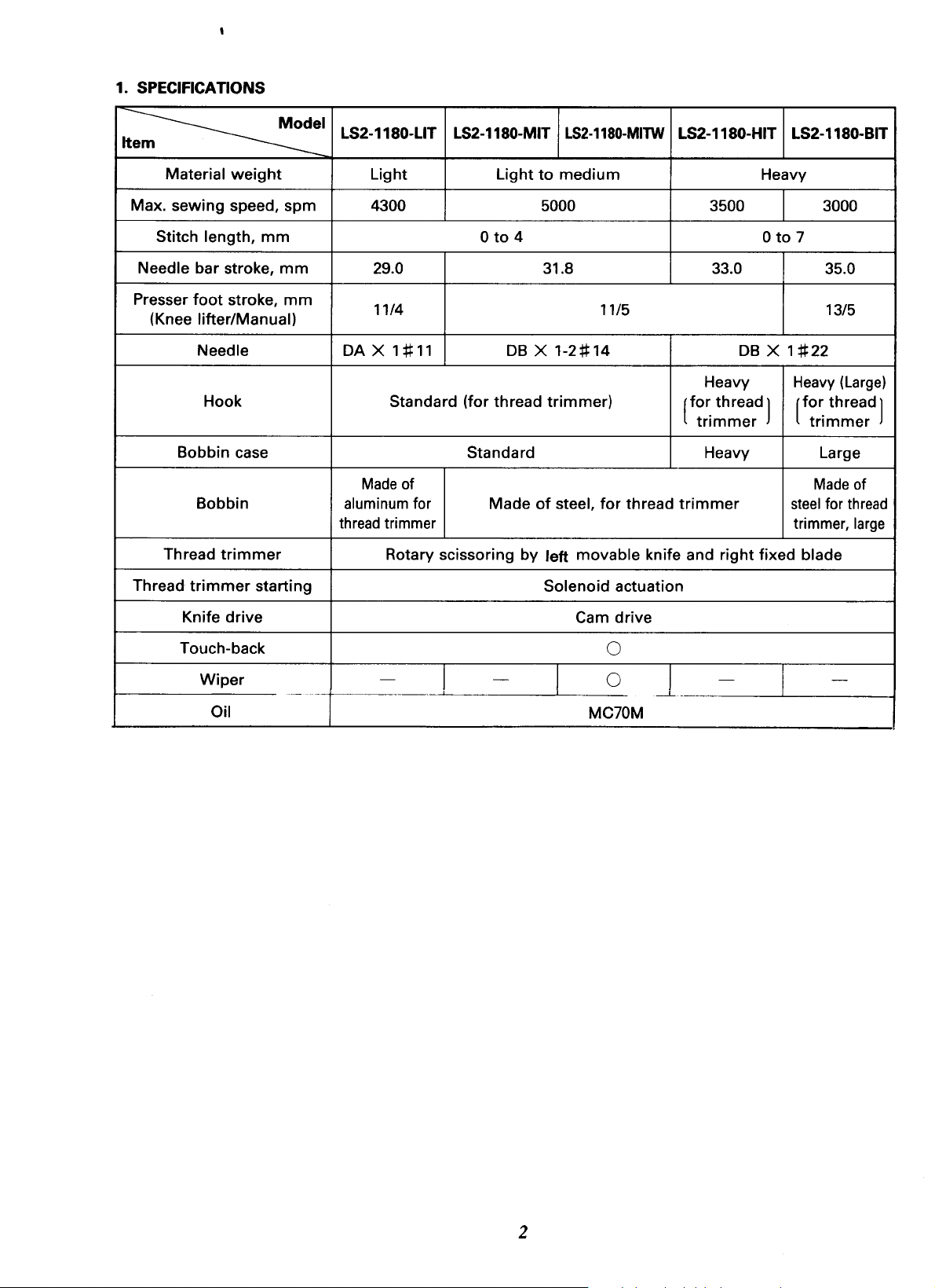
1. SPECIFICATIONS
~I
It
Material
Max. sewing speed,
Stitch
Needle bar stroke,
Presser
(Knee lifter/Manual)
Bobbin case
Thread
Thread
weight
length,
foot
stroke,
Needle
Hook Standard (for thread
Bobbin
trimmer
trimmer
spm
mm
mm
mm
starting
LS2-1180-LIT LS2-1180-MIT
Light
4300 5000
29.0
11/4 11/5 13/5
DA X 1
aluminum for
thread
#11
Made
of
trimmer
Rotary scissoring
Light
0
to
4
DB X 1-2#14
Standard Heavy Large
Made
LS2-1180-MITW
to
medium
31.8 33.0 35.0
trimmer)
of
steel,
for
thread
by
left
movable
Solenoid actuation
LS2-1180-HIT LS2-1180-BIT
Heavy
3500 3000
0
to
DB
X 1
Heavy
[fo~
thread]
tnmmer
trimmer
knife and
right
fixed blade
7
#22
Heavy
[
fo~
thread]
tnmmer
Made
steel
for
trimmer,
(Large)
of
thread
large
Knife
drive
Touch-back
Wiper
Oil
Cam
drive
0
-~·-
------·
--
-
-
0
MC70M
j_
-
-
2
Page 4
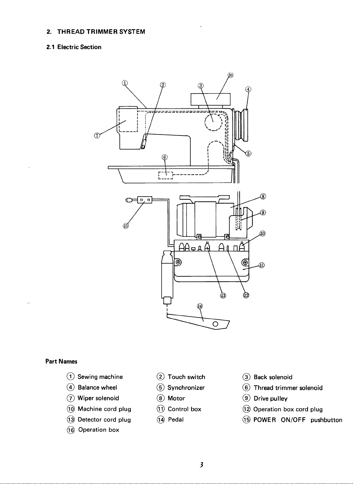
2.
THREAD
2.1
Electric Section
TRIMMER
SYSTEM
i-
L----'
-.,_
________
./
Part Names
G) Sewing machine
@ Balance wheel
(j) Wiper solenoid
5
® Touch switch
® Synchronizer
®Motor
® Back solenoid
® Thread
trimmer
® Drive pulley
solenoid
@ Machine cord plug
@ Detector cord plug
@ Control box
@Pedal
@ Operation box
3
@ Operation box cord plug
@
POWER
ON/OFF
pushbutton
Page 5
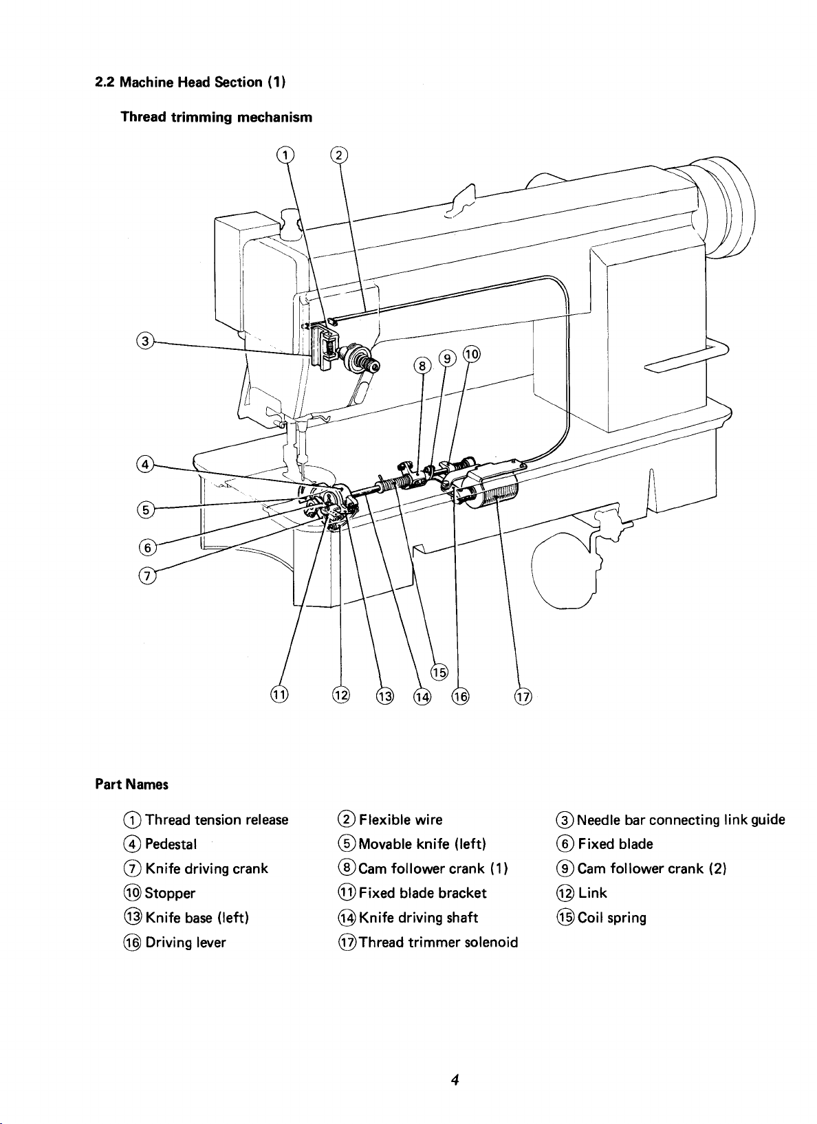
2.2 Machine
Head
Section ( 1)
Thread
trimming
mechanism
Names
Part
CD
Thread tension
@Pedestal
(j)
Knife driving crank
@stopper
@Knife
base
@ Driving lever
(left)
release
®Flexible
®Movable
®cam
wire
knife (left)
follower crank (1)
@ Fixed blade bracket
@Knife
@Thread
driving shaft
trimmer
solenoid
4
@Needle
®Fixed
®Cam
@Link
@Coil
follower crank (2)
spring
bar connecting link guide
blade
Page 6

2.3
Machine
Touch back mechanism
Head
Section (2)
Part Names
G) cover
@Coil
0Pin
spring
@ Micro switch
@Side
@Bushing
@Reverse sewing crank
@Spring
cover
bracket
@Switch
@Link
@Wiper
@Pushbutton
@Plunger
@Feed
@
@Solenoid
regulator
Reverse
sewing lever
mounting bracket
cam
5
®Wiper
®Wiper
@Switch
solenoid
bracket
bracket
@ Back solenoid
@Link
@Spring
@For
bracket
reverse
sewing
Page 7

3.
PREPARATIONS BEFORE OPERATION
3.1
Installation
of
Sewing Machine and
Motor
Operation
Operation
Receptacles
~l
box
(option)
box
(option)
for
machine cords
hole
Round
------
Passing the Machine cords
in table
~
Wiring between sewing machine and control box
Note:
Before plugging
Pass
two
cables
plugs
into
the respective
or
unplugging, be sure to
from
the sewing machine through the
plug
receptacles.
turn
[[oop
off
the POWER
Operation
Detector
Connectors location on
•
the
control
'·DoD
I "
External knob 1-2 position select switch
round
ON/OFF
hole
pushbutton.
in the table
and
connect the
Machine
box
box
0
oo]j
two
6
Page 8

3.2
Adjustment
of
Machine
Stop
Position
Adjust
3.2.1
When
machine
deviate
(1) Disconnect
(2) Run
(3)
3.2.2
Adjust
When
"DOWN"
than 3
(1) Disconnect
(2)
of
"UP"
the
stops at
larger than 3
the
machine
the
While
tool"
holding
in
of
"DOWN"
the
pedal is Newtral
position.
mm
the
machine
Run the
tion.
position
pedal is kicked
"UP"
the
mm
plug
position.
adjust
(12 pins)
head.
machine
the
the
hole
and
stop
pully
@,then
position
If
the
adjust
the
as
follows.
plug
(12 pins)
head.
machine
and stop at
down
insert
the
by
heel,
If
the
marks
as
follows.
of
cable
from
at
"UP"
position.
the
"adjusting
remove
the
tool.
machine stops as
the
marks deviate larger
of
cable
from
"DOWN"
posi-
3rd
mark
Pully
(3)
3.2.3
While
tool"
Comfirm
pins)
holding
in
the
coming
receptacle.
4. ADJUSTMENTS
4.1
How
to
Adjust
The standard
~lass
Item
Needle lift-up
lowest position
Distance between
needle hole and hook
Distance between needle
hook point
Distance between
needle plate setting base, in highest
position
of
needle bar
the
hole@,
stop
from
the
timing
quantity
upper
needle
the
pully
insert
the
then
remove
operation
the
Timing
then
machine
between
head
Needle and
between needle and
·L
point
from@
side
point
of
and©
1.8 2.0 1.8 1.8
@
0-0.2
0.05 0.05 0.05 0.05
and
17.3 18.8
"adjusting
the
tool.
the
plug
(12
into
the
hook
is
·M
- - -
18.8
Hook
following
·B
(mm)
·H
20.6
the
table.
®
' '
H
' I
I :
' '
'.'
(/:0
\ty
"Up"
"Down"
position
position
7
Fig.1
Page 9

4.2 Thread
Trimmer
Mechanism
4.2.1 Construction
Knife
driving
4.2.2 Cautions on
adjustment
A hook shaft cam system
sewing machine,
if
the sewing machine
operating state (the roller
knife
state
makes
only
contact
with
during a normal thread
Knife
driving
shaft
Cam
follower
the thread
is
rotated one
crank (2)
Fig.
trimmer
is
engaged
is
of
crank
utilized
cam
follower
for
the needle, resulting in damage.
trimming
cycle (Needle DOWN position
crank
2 Cam
turn
Be
Thread
(1)
Driving
follower
trimmer
crank
solenoid
Flexible
=~,.
lever
(2)
Stopper
wire
,p,;ng
drive. Therefore, during the adjustment
with
with
sure
the thread
the thread
to
bring the solenoid
to
trimmer
trimmer
UP
position).
solenoid in the
cam), the movable
into
the operating
of
4.2.3
Installation
4.2.3.1 Knife base
(1)
As
shown in Fig.
hook shaft bushing
of
knife base and fixed blade bracket
unit
3,
fit
(left) and
@.
4.2.3.2 Fixed blade bracket
(
1)
As shown in Fig.
unit
with
fix
then
with
4,
install the fixed blade bracket
the
hook
positioner dismounted, and
the screws ® .
the
unit
knife
fix
base
with
unit
to
the
the screws
unit
Fig.
3
8
Fig.
4
Page 10

4.2.3.3 Relation between fixed blade and movable knife (left)
edge
(
1)
Fig. 5 shows the standard state.
If
(2)
the dimension indicated in Fig. 5
three-thread breakage
will occur, leading
is
too
to
thread cast-off, etc. after the thread trimming.
Reversely,
the dimension
is
too
small, thread
if
trimming error may result. Therefore, caution must
be
exercised.
(3) Make the adjustment in (2) in the
procedure
installation procedure
4.2.4 Connection
(1) Make connection
use
care
of
fixed blade bracket
of
fixed blade.
of
knife
base
as
shown in Fig.
for
the position
and knife driving crank
of
link
installation
unit
or
6.
At
this time,
depends on the
sewing machine model.
large,
needle
in the
(Knife
Fixed
edge)
blade
LS2-1180-LIT
LS2-1180-MIT
LS2-1180-HIT
0.3mm
0
0
Fig. 5
LS2-1180-BIT
4.2.5 Knife driving shaft and related parts
Cam
follower
90.5mm
(BIT:
87.5
mm)
(1) Fig. 7 shows the standard setting position.
(2) During assembling,
(3) Fix the
(4)
Fix
cam
the stopper
be
follower
to
the
sure
to
crank (1)
recess
pass
the knife driving shaft through the knife driving crank first.
to
the
recess
so
that
the knife driving shaft
axial direction.
crank
(1)
Cam
follower
Knife
Fig. 7
of
knife driving shaft at the position shown in Fig.
driving
crank
shaft
(2)
can
rotate smoothly
without
7.
play in the
9
Page 11

4.2.6 Installation
of
thread
trimmer
solenoid
unit
(1) Operation stroke
CD
Standard operation stroke
of
thread
@ Adjust the operation stroke
(2) Installation
CD
Install the
Fig.
@ Install the
provided between the driving lever and cam
crank (2)
the solenoid.
@
When
clearance
follower cranks (1)
is
by moving the
arrow direction in Fig. 8
of
unit
unit
with
8.
unit
so
with
the stopper
the solenoid
of
is
0.5 mm
and
the standard installation status. Make adjustment
solenoid mounting bracket in the
trimmer
the
screws@
that
solenoid
is
6.0 mm.
by
use
of
the
nut
and©
shown in
approximately 1 mm
@.
is
follower
nut
® in contact
with
energized under this condition,
is
provided between the
(2)
as
shown in Fig.
9.
cam
This
Fig. 8
Fig. 9
4.2.7
Installation
(1)
Align the second timing mark ® on the pulley
of
thread
trimmer
cam
matching mark on the arm.
Set the thread
(2)
turn the thread
cam
makes contact
the operation
cam
(3)
the
When
and the
clearance between the
Thread
trimmer
trimmer
trimmer
of
follower
cam
_,.
solenoid
cam
with
the roller,
thread
trimmer
crank (2)
cam
and roller end
to
the operation state and
forward.
At
fix
the cam.
solenoid
has
returned, the standard
is
the
0.5
point
has
to
with
where
been
reset
1.0 mm.
the
Thread
trimmer
cam
0.5
to
1.0
mm
Fig. 10
10
Page 12

The
Note:
4.2.8 Adjustment
(
1)
Positions
CD
Fig.
standard
to
the operation
position
the stopper plate, make adjustment
screw (Fig.
of
movable knife (left) and fixed blade
12
shows the standard state.
position
is
has
been changed,
7)
and
then make adjustment in (1) to (3).
of
knife engagement
of
cam
follower
shown in Fig.
for
example,
crank (2)
11.
When
by
removing
with
the adjust
prior
this
Cam
Movable
LS2-1180-BIT
'~~~.
/g~haft
follower
crank
.(q/
t.l._,.
(2)
1 -
knife
Roller
Knife
driving
shaft
(left)
7mm
(BIT:
7.5
mm)
Fig.
I
J
•
I
2.5
LS2-1180-LIT
LS2-1180-M IT
LS2-1180-HIT
1
·~;
)u.~
'-
r
·,,/
11
Fixed
blade
m
(2) Adjustment
CD
Set the solenoid
sewing machine. Then, the
by the thread
has
amount
of
moved
is
knife engagement amount
to
the operation state and rotate the
trimmer
to
the maximum, the standard engagement
1.5
to
2.0 mm.
cam.
See
® Make adjustment by the installation
(3) Adjustment
CD
The standard knife engaging pressure
movable knife (left) and fixed blade start making contact
with
®
When
thread, a slight increase
produces
of
knife engagement pressure
each
other at the position shown in Fig.
cutting action
an
effect.
is
poor especially
movable knife (left)
When
the movable knife (left)
Fig.
13.
of
knife driving crank.
is
obtained when the
14.
because
of
the engagement pressure
is
rotated
of
thick
Knife
Movable
driving
knife
1.5
to
(left)
crank
Fig. 12
2.0
mm
Fig. 13
Fixed
blade
®
To
adjust the engagement pressure, loosen the lock
in Fig.
11
and adjust
with
the adjust screw @.
nut@
11
Fig.
14
Page 13

4.2.9
Adjustment
of
needle thread tension releasing
amount
Thread
trimmer
solenoid
(
1)
Make adjustment
operated, the tension discs
approximately 1 mm.
(2) To make adjustment, loosen the nuts ® and move the flexible
wire.
CAUTION
If
the opening
thread
thread cast-off. Reversely,
too
leading
4.3
Adjustment
(
1)
Adjust
pretension adjust
Clockwise
wise
will
large, the tension discs
to
loose stitches.
the
turn
turn
increases the length.
so
that
when the thread
of
thread tension regulator open
of
tension discs
be
trimmed
of
Needle Thread Remaining Length
remaining length
nut
reduces the remaining length. Counterclock-
at
short length, leading
if
@.
is
too
the opening
are
left
of
needle thread
trimmer
small, the needle
to
of
tension discs
opened continuously,
by
solenoid
needle
is
use
of
the
is
...
Fig. 15
4.4 Cautions on Installation
Adjust
that
twisted, and make sure
smoothly in the vertical direction.
mounting
4.5 Touch-Back Pushbutton
The
(
1)
the position
the plunger
screws.
function
Normally,
Fig.
pushbutton
of
18.
of
of
solenoid and the
See
pushbutton
this pushbutton
When the sewing machine
is
pressed, reverse stitching
of
Touch-Back Solenoid
solenoid in the longitudinal direction
that
the
Fig.
17.
can
be
eliminated
is
used
link
(for
connection) are
reverse
sewing lever moves
After
at
that, tighten the
as
required.
the position shown in
is
operated
is
performed.
after
so
not
the
Fig. 16
@
@rr,
~
--
-::::.=-=
--
==:
Feed regulating lever
Fig. 17
)
(2) When the pushbutton
the broken line in Fig.
it
is
pressed.
is
moved
18,
the switch does
to
the position indicated
not
function
even
12
by
if
Fig. 18
Page 14

4.6 Wiper
4.6.1
Height
1)
The standard height
(
which
of
is
stopped at the
wiper
of
wiper
UP
position.
is
2 mm below the
tip
of
needle
(2) Make adjustment after
loosening the
4.6.2 Wiper operation position
(
1)
The standard operation position
of
the center
fully
To
(2)
pushed (when the solenoid
make adjustment, loosen the
needle when the plunger
adjust the mounting position
of
4.7 Adjustment
Forward and
screw@.
of
wiper
is
energized).
screws
of
solenoid unit.
Reverse
Stitch Lengths
is 0 to
of
2 mm from
wiper solenoid
is
@ and © and then
Fig. 19
(
1)
Loosen the screw @ and make adjustment by turning the
eccentric
length and
wise
reverse
4.8 Adjustment
(1) To adjust the inclination
turn the eccentric pin
tilt.
turn
shaft@.
increases
increases
Clockwise turn reduces the forward stitch
the
the forward stitch length and
stitch length.
of
Feed
Dog Inclination
of
@.
Counterclockwise turn
reverse
stitch length. Counterclock-
feed dog, loosen the
Clockwise turn
sets
to
upward
tilt.
sets
decreases
screw@
to
downward
the
Fig. 20
and
13
Fig.
21
Page 15

4.9
Timing
of
Feed
Needle
1)
The position
(
tip
is
located
needle plate when the feed dog
and the teeth
needle plate.
(2)
Make
adjustment
To install,
ing hole on a
4.10
Hook,
( 1)
Use
the
slit
guide
for
approximately 3 mm
of
See
timing
upper
Bobbin
Case,
undertrimmer
@
as
the standard feed
feed dog align
Fig. 22.
by the
mark on a feed cam is according
shaft,
and Bobbin
shown in Fig.
is
mounting
by
set screw
hook
which
24.
timing
sunk
with
positions
is
where the needle
below the
by
turning
the upper surface
of
as
shown
has
the bobbin thread
top
surface
the
pulley
feed cam.
with
in Fig.
oil-
23.
N~d·s~
of
of
~-~t---.Ll3mm
Feed dog Fig.
Rubber cap
Set screw
Fig.
22
23
Timming
mark
(2)
Use
the
bobbin
@ at the
(3)
For the bobbin, use the attached bobbin. The standard bobbin
of
Model -L sewing machine is made
order
to
prevent the
as
lightly
bottom
as
possible.
case
which
as
shown in Fig. 25.
deformation
has
idel running prevention spring
of
aluminum.
of
bobbin,
wind
the thread
In
Fig.
24
Fig. 25
14
Page 16

5.
TROUBLESHOOTING
Trouble
Thread cannot
me
d.
Neeedle thread comes
out
of
start
the needle
of
stitching.
be
trim-
at
the
Cause
Knife
engagement
Knife engaging pressure
Damage and/or wear
of
movable knife (left). fixed blade
Machine stops
Machine stop position varies largely.
Position
Since the movable knife (left)
operated
cannot
At
thread tension regulator
open.
of
too
be
the time
is
improper.
is
too
of
cutting
too
early.
fixed blade
early, loop spreading
performed
of
is
improper.
by
the knife.
thread trimming,
discs
do
low.
edge
not
Corrective
is
Adjust
Adjust
Change
Adjust
1.
2.
Adjust
Adjust
trimmer
Adjust
releasing.
the engagement amount.
the engaging pressure.
the knife and/or blade.
the stop position.
Check needle thread tension
time
of
thread trimming.
In the
machine, check table specifications
(motor
box G switch
case
pulley diameter, control
the position
the installation
cam.
the needle thread tension
of
ON).
Action
Model
of
at
the
-H
or
-B
fixed blade.
of
thread
Reference
Section
4.1.8
4.1.8
3.2
4.1.9
4.1.3
4.1.7
4.1.9
Skip stitch at the start
stitching
Needle thread
after thread
is
too
long Pretension
trimming.
Thread
Thread
before the
knife
blade.
Needle
the thread.
Pretension
Bobbin thread becomes short due
of
the idle running
thread trimming.
Tension
The remaining length
thread on the needle side
after thread
Thread
Thread movement between the
and the hook positioner
smooth.
trimmer
is
trimmed
cutting
(left)
engage
is
too
is
too
of
bobbin thread
trimming.
is
too
trimmer
timing
by the fixed blade
edge
with
thick
with
strong.
of
weak.
timing
is
too
early.
of
movable
the
fixed
respect
bobbin at the
is
of
is
is
too
too
too
high.
needle
short
late.
hook
is
not
to
to
Adjust
trimmer
Adjust
Adjust
Use
prevention spring.
Adjust
1.
2.
3.
Adjust
Adjust
trimmer
the installation
cam.
the position
the pretension. 4.2
a bobbin
the tension
Adjust
Check the installation
trimmer
Check the thread contact
the pretension. 4.2
case
the pretension.
cam.
the installation
cam.
of
of
fixed blade. 4.1.3
with
idle running
of
bobbin thread.
of
of
thread 4.1.7
4.9
4.2
thread
area.
thread 4.1.7
4.1.7
15
 Loading...