

Page 1
USER S MANUAL
Page 2

Eng lish-1
Features ............................ .. ... ..... ............................................ ..... ......................................................................................... ...Engl ish-2
Important Information ........................................ ................................................. ...... ...... ....................................... .... ...... ........English-3
Declaration ........................................ ...... ............................................. ...... ............................................. .................................English-5
Safety Precautions, Ma int enan ce & Recomm ended Use ............................................................................ .... ..... . .................E nglish-6
Contents ......................................................................................... ...... ...... ..............................................................................English-7
Part s Name and Functions .......................... .............................................. ..... ...... ............................................... ... ... ...............E nglish-8
Buttons, Switch, and Indi cator ......................................................... ...... ..... ............................................ .... ...... ........English-8
Connectors an d Terminals ............................................................... .........................................................................English-9
Wireless Remote Control .... ............ ........... ........... ...... ........... ............ ........... ...... ........... ..... .......... ...... .... ... ...............English-10
How to Use the Wireless Remote Cont rol ............................................................... ..... ...... ......................................English-11
Prepar ation for use .. ..... ............................................... ................................................ ............................................................Engli sh - 12
Fl ow of preparation ..... ...... ............................................... ...... ............................................ .......................................English-12
[P-1] Pr eparation for installati on . ...... ....... ................................................. ...... ...... ............................................ ... ... ...............E nglish-13
Determine the installat ion location .............................................................. ...... ...... ................................... ...... ...... ...English-13
Ventil ation requi rements for enclosure mounting ............................................................... ....... ...............................English-13
[P-2] Installing the monitor .....................................................................................................................................................English-14
Installing and removing the stands ........... ...... ...... ................................................. ...... .............................................English-14
Installing the main switch cove r ........................................................................ ........................................................English-14
Using the wall mount or ceiling moun t ................................................... ..... .......................................... .. ... ...............E nglish-14
Installing in the portrait position .......................... ...... ..... .............................................. ....................................... ......English-15
[P-3] Installing the speakers .................................................................. ....... ............................................. ...... .... ..................Engli sh - 16
[P-4] Connection procedur e .................................. ..... ............................................. ...... ....................................... .... ...... .......English-17
Wiring diagram ............. ...... ..... ............................................. ...... ...... .........................................................................English-17
Prevention of disconnection of HD MI cable ................................................................. ........................................ ....English-17
Connecti ng with a computer (analog connection) .............. ............................................... ...... ...... ...........................En glish-18
Connecti ng with a computer (digital connection) ........................... ............................................... .. .........................English-19
Connecti ng a video device (component video/H DMI device) ..................................................................................English-20
Connecti ng a video device (composite video/S video device)/stereo ampli er ............................................. ...
......E nglish-21
[P-5] Connecting the power cord to the m onitor .......................... .......................................... ..... .........................................English-22
Connecti ng the power source ................................................................................................ ...................................English-22
How to Use ........................................................... ........... ...... ........... ........... ............ ..... ............................................................E nglish-23
Fl ow of How to Using .................................. ............................................... ...... ..................................... ... ... ..............E nglish-23
[U-1] Turning on all the connected devices ................................................................................................... ........................English-24
Turning on external devices ................................ ...... .......................................... ..... ..... ...... .... ..................................English-24
Turning on the monitor . ...... ...... ............................................. ...... ......................................... .....................................English-24
Power Mana gement Function ..................................................................... ..... ........................................ ....... ...... ....Engl ish-24
[U-2] Selecting the video input ............................................................................. ....................................... ..........................English-25
[U-3] Controlling the external devices ............................................. ...... ............................................. ...... .............................English-26
[U-4] Auto-setup ....................................................................................................................................................................Engli sh-26
[U-5] Selecting the picture mode ............................................................. ....... ........................................ ...... .........................English-26
[U-6] Screen adjustm ent ............................................................. ...... ............................................. ........................................English-27
[U-7] Picture adjustment ............................................................................... ..... ............................................. ..... . ...... ...........English-27
[U-8] Volume cont rol ..... .... .. ............................................. ...... ........................................... .....................................................English-28
[U-9] Schedule setting ................................................................................................................................... ...... . ..... ............English-28
How to set up schedule ................................ ..... .............................................. ..... .................................... ... ..... .........English-29
[U-10] Remot e contr ol ... ...... ........... ............ ..... ............ ........... ........... ...... ........... ............ .... ....... ...............................................English-30
RS-232C Remote cont rol .......................................... ..... ...... ............................................. ........................................English-30
Con
gurati on and basic operati on of OSD scr een ..................................................... ........... ............ ...... .... ...........................English-32
Con
guration of OSD scr een ................................................................................................. ...................................English-32
Basic operation of OSD ................................................... ............................................. .............................................English-33
OSD scr een functions ......................................................... ...... ...... .................................................................................. .......English-34
Ot her functi ons .................................................................... ...... ....................................... .......................................................English-42
Picture size ...................................................................................................................................................... ...... ....English-42
Picture mode .......................................................................................................................................... ...................E nglish-42
A udio input change ....................... ...... ............................................. ...... ...... .............................................................English-42
OSD information .................................................................................................. ...... ..................................... ...... .....English-42
Control Lock mode .................................................... ..... ...... .................................................................................. ...Engl ish-42
PIP, P OP function .. ...... ............ ............ ............ ..... ............ ............ ............ ...... ........... .... .......... ...... ............................English-43
Troubleshooting ................................................................ ...... ............................................ .....................................................English-44
Speci
cat ions .......................... ...... ............ ........... ............ ...... ............ ........... ............ ...... ... .... ...... ...........................................English-45
Pin Assignment .............................................................. ..... ...... .................................................................................... ...........English-46
Index
Page 3

Eng lish-2
Features
Wide-range Color Temperature A djustment Page 34
T he display color temperatures can be adjusted from 2,600 K to 10 ,000 K. Such a wide range adjustment is important for indu stri es
such as broadcasters and food retailers where color accuracy and esh tones are critical.
Tiling Capability with Frame co mpensation Page 39
Up to 25 panels (5 wide x 5 high) can be combined to create a single large image (i.e., video wall) or oth er high-im pa ct signage. A
fram e compesation function i s i ncorporated to compensate the width of panel bezels so that images are displayed with the utmost
accuracy.
PiP, PoP and Side-by-side Pages 37 and 43
Picture-in-Picture and Pic ture- out-of-Picture are available when you want to display video c ontent from a video input source in the
sub picture and display the PC input source in the main picture, and vi ce versa.
T he native resolution a s high as 1
x can displ ay these two input sources in the Side-by-si de mode, ideal for broadcastin g
and video-confer encing appli cations.
Programmable Scheduling F unction Pages 28, 29 and 38
The monitor s operating schedule can be programmed for up to seven different sc heduled time intervals by time, day of the week
and input port. This allows video content from different inputs to be displayed on certain monito rs within the same installation
ac cording to the sc hedule, and extends the mo nitor s life and saves the power by turning it off during those hours or days it i
s n ot in
use.
Screen-saver F unctions Page 40
To reduce image persist ence and maximize the pan el life in demand ing signage applications, th e LDT Series is equ ipped wi th f our
screen -saver functions.
GAMMA
COOLING FAN
BRIGHTNES S
MOTION
Side Bo rder Co lor Selec t Page 40
When the 4: 3 screen is displayed, the side border color can be selected from black, gr ay and whi te.
Power-on Delay Page 39
For installatio ns employing numerous monito rs, the power-on delay function c an power up the monitors sequentially with delay
between 2-50 seconds af ter the power is applied. Usin g this funct ion can prev ent inrush current probl ems and reduce the overall
electrical loa d requirements when a s ingle power supp ly is used.
Flexible Landsc ape & Portrait Positioning Page 15
Designed to enhanc e for heat dissipation and long-term reliability in both landscape (ho rizontal) and portrait (vertic al) positio ns.
Closed Caption Page 39
You can display captions .
When closed-caption video sign a ls are input, you can select to display or hide the captions on the screen.
This monitor is compliant with EIA -608- A.
Page 4
Eng lish- 3
D ECLA RATION OF CONFORMITY
This device c omplies with Part 15 of FCC Rules. Operation is subjec t to the following two c o nditio ns. (1) This devic e may no t
cause harmful interference, and (2) this devic e must accept any interferenc e rec eived, inc luding interferenc e that may c ause
undesired operation.
U.S. Responsible Party: Mitsubishi Digital Electronics Americ a, Inc.
Address: 9351 Jeronimo Road,
Irvine, California 92618 U.S.A.
Tel. No.: +1 - (949) 465-6000
Type of Product: Computer M onitor
Equipment Classi
cation: Class B Peripheral
Model: LDT323V (BH030)
Win dows is a registered trademark of Mi crosoft Corporation. All other brands and product names are trademarks or
registered trademarks of their respective own ers.
HDMI, the HDMI lo g o and High- De
nition Multimedia Interface are trademarks or registered trademarks of HDMI Licensing
LLC.
Canadian Department of Communications Compliance Statement
DOC: This Class B digital apparatus meets all requirements of the Canadian Interference-Causing Equipment Regulations.
C-UL: Bears the C-UL Mark and is in compliance with Canadian Safety Regulati ons according to CAN/CSA C22.2
No. 60950-1.
FCC Info rmation
1 . Use the attached speci ed cables with this equipment so as not to interfere with radio and television reception.
(1) T he power supply cord you use must have been approved by and comply wit h the safety standards of U.S.A.,
(2) Please use the supplied s hielded video signal cable. Use of ot her cables and a dapter s may caus e interference with radio and
television rec eption.
2.
T his equipment has been tested and found to compl y with the limits for a Class B di gital device, pursu ant to part 15 of the
FCC Rules. These limits are designed to provide reasonable protection against harmful interference in a residential installation.
This equipment generates, uses, and c an radiate radio frequenc y energy, and, if not installed and used in ac cordance with the
instru ctions, may cause harmful interference to radio communications. However, there is no g uarantee that interference will not
oc cur in a particular installation. If this equipment do es c ause harmful interferenc e to radio or television reception, which can be
determined by turning the equipment off and o n, the user is enc ouraged to try to co rrect the interferenc e by one or more of the
following measures:
Reorient or relo c ate the rec eiving antenna.
Increase the separat ion between the equipment and receiver.
Connect the equipment into an outlet on a circuit different from that to which the receiver is connec ted.
Consult your dealer or an experienced radio/ TV technician for help.
3.
You are cautioned that ch anges o r mod i cat ions not expressly approved by the party resp onsible for compliance could void
your authority to operate the equipment.
Impo rtant Info rmation
Page 5
Eng lish- 4
Important Information (continued)
TO PREVENT FIRE OR SHOCK HAZ ARDS, DO NOT EXPOSE THIS UNIT TO RAIN OR MOISTURE. ALS O, DO NOT USE THIS UNIT S
POLARIZED PLUG WITH AN E X TE NSION CORD RECE PTACLE OR OTHER OUTLETS UNLESS THE PRONGS CAN BE FULLY IN SE RTE D.
REFRAIN FROM OPENING THE CABINET AS THERE ARE HIGH VOLTAGE COMPONENTS INSIDE.
REFER SERVICING TO QUALIFIED SERVICE PERS ONNEL.
TO R EDUCE THE RISK OF E LE CTRIC SHOCK, MAKE SURE POWER CORD IS UNP LUGGED FROM WALL SOCK ET. TO
FULLY DISENGAGE THE POWER TO THE UNIT, PLEAS E DISCONNECT THE POWER CORD FROM THE AC OUTLET. DO
NOT REMOVE COVER (OR BACK). NO U SER SERVICEABLE P ARTS INSIDE. REFER SERVICING TO QUALIFIED SERVICE
PERSONNEL.
This symbol warns user that uninsulated voltage within the unit may have suf
cient m agn itude to cause electric shock .
Therefore, it is dangerous to make any kind of contac t with any part inside this unit.
This symbol alerts the user that important literature c oncerning the operation and maintenance of this unit has been
included. Therefore, it sho uld be read c arefully in o rder to avoid any problems.
WARNING
CAUTION
CAUTI ON:
This LCD Monitor uses a lamp that contains me rcury. Disposal of the lamp or the LCD Monitor with the lamp may be
regulated due to environmental c onsiderations. For dispo sal or recycling informatio n, please c ontac t your local authorities or
the Electro nic Industries Allianc e.
CAUTION
Page 6
Eng lish- 5
W e h ereby cert ify t hat the color monitor LDT323V (BH030)
is in compliance with
Council Directive 2006/95/EC:
EN 60950-1
Council Directive 2004/108/EC:
EN 55022
EN 61000-3-2
EN 61000-3-3
EN 55024
and marked wit h
Mitsubishi Electric Corporation
2-7-3, Marunouchi,
Chiyoda-K u
Tokyo 100-8310, Japan
Declaration
Declaration of the Manufacturer
Warning
This is a Class A product. In a domestic environment this pr oduct may cause radio interference, in which case the
user may be required to take adequate measures.
Page 7

Eng lish- 6
FOR OPTIMUM PERFORMANCE, PLEASE NOTE
THE FOLLOWING WHEN SETTING UP AND USING
THE LCD COLOR MONITOR:
DO NOT REMOVE MO NITOR BACK COVER. There are
n o user serviceable parts inside and open ing or removing
covers may expose you to dangerous shock hazards or
other risks.
Refer all servic ing to quali
ed service personnel.
Do not spill any liquids into the c abinet or use your monito r
near water.
Do not insert objects of any kind in to the cabinet slots,
as they may touc h dangerous voltage points, which can
be harmful or fatal or may c aus e ele ctric sho ck,
re o r
equ ipment f ailure.
Do not place any heavy objects on the power cord.
Damage to the c ord may c ause shock or re.
Do not place this prod uct on a s loping or unstable cart,
stand or table, as the monitor may fall, causing serious
damage to the mo nito r.
When operating th e LCD monitor, use the power supply
cord provided with the m onitor.
If no power cord is supplied with this equipment, please
contact your suppli er.
For all other cases, use a power c o rd that matc hes the AC
voltage of the power outl et and has been approved by and
complies with the safety standard of your particular country.
Do not plac e any objects onto the monitor and do no t use
the mo nitor outdoors.
The inside o f the
uorescent tube lo cated within the LCD
monitor contains mercury. Please follow the bylaws or r ul es
of your munic ipality to dispose o f the tube properly.
Do not bend power co rd.
Do not use monito r in high temperature, humid, dusty, o r
oily areas.
If monitor or glass is broken, do not come in contact with
the liquid c rystal and handle with c are.
If the LCD monitor is dama ged and the liquid crystal leaks
out, do not inhale or swallow it.
Allow adequate ventilation around t he moni tor, so that heat
can properly dissipa te. Do not block vent ilated open ings or
place the monitor near a radiat or or other heat sour ces.
Do not put anything on top of the monito r.
The power cabl e connector is the pri mary means of
detaching the system from the power supply. The monitor
should be installed close to a power outlet, which is easily
accessible.
Handle with care wh en t ransporting. Save packaging for
transporting.
Please clean the holes of back ca bi net to reject dirt and
dust at least once a year because of set reliability.
If using the c oo ling fan c ontinuously, it s rec ommended to
wipe holes a minimum of once a month.
Wh en insta ll ing the remote control batteries;
- Align the batteries acco rding to the (+) and (-) indic ations
inside the case.
- Align the (-) indication of the batteries rst inside the
case.
CAUTION:
Immediately unplug your monitor from the wall outlet and refer
servicing to quali
ed servic e perso nnel under the fo llowing
conditions:
When the power supply cord or plug i s damaged.
If liquid has been spilled, o r objec ts have fallen into the
monitor.
I f the monitor has been exposed to rain or water.
If the monitor has been dropped or t he cabinet damaged.
I f the monitor does not operate normally by following
operating instructio ns.
Rec ommend Use
CAUTION:
For optimum performanc e, allow 20 minutes for warm-up.
Rest your eyes periodically by focusing on an object at least
5 feet away. Bl ink often.
Position the monitor at a 90 angle to windows and other
light sources to minimize glare and re ect ions.
Clean the LCD monitor surfac e with a lint-free, non-abrasive
cloth. Avoid using any cleaning solution or glass cleaner!
Adjust the monitor s brightness, contrast , and sharpness
controls to enhance readability.
Avoid displaying
xed patterns o n the monito r for long
periods o f time to avoid image persistenc e (after image
effects).
Ge t regular eye c hec kups .
Ergono mic s
To realize the maximum ergonomic bene
ts, we recommend
the following:
Use the preset Size and Position contr ols with standa rd
signals.
Use t he pr eset Color Setting.
Use non-interlaced signals.
Do not use pri m ary color blue on a dark background, as
it is dif cult to see and may produce eye f ati gue due t o
insuf
cient contrast.
Safety Precautions, Maintenance & Recommended Use
Page 8
Eng lish-7
31.5" LCD Display Monitor
USER S MANUAL
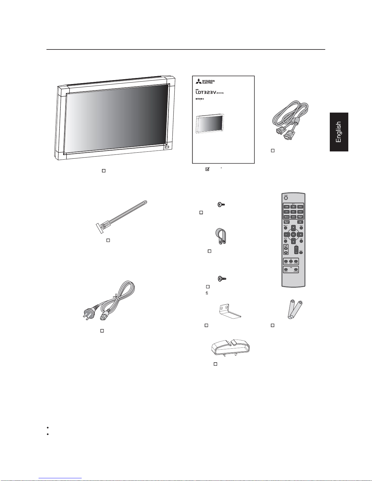
Contents
Power Cord
Vide o Signal Cab le
(Mini D-SUB 15-pin to
Mini D-SUB 15-pin Cable)
Clamper x 2
(To prevent from fallin g)
Screw (3x6) x 2
(To
x Main switc h c over)
Main switch cover
Cable Holder
Wireless Remote
Control an d AAA
Batteries
Your LCD monitor (LDT323V) comes with the following:
The following components are supplied as option.
Exte rna l S p ea kers
Stands
Screw (M4x8) x 2
(For Clamper)
Clamper x 2
(For sec uring the power
cord and HDMI cab le)
LCD Mo nito r
Use r s Manual
Page 9
Eng lish- 8
1
2
3456789
10
5
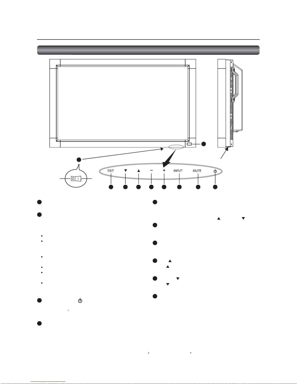
INP UT b u t t o n
Displays the OSD menu to switch the video input.
You can select [RGB1], [RGB 2], [RGB3], [RG B4], [DVD/HD],
[V IDEO<S>], or [VIDEO] using th e UP (
) or DOWN ( ) button.
6 PL US (+) button
A cts as (+) button to increase the adjustment in t he OSD men u.
Increases the audio output level when the OSD menu is off.
7
MINUS (-) butto n
Acts as (-) button to decrease the adjustment in the OSD menu.
Dec reases the audio output level when the OSD menu is off.
8 UP ( ) button
Acts as button to move the highlighted ar ea up to select an
adjustment item in the OSD menu.
9 DO WN ( ) button
Acts as butto n to move the highlighted area down to selec t
an adjustment item in the OSD menu.
10
EXIT b u tto n
Activates the OSD menu wh en the OSD menu is off.
Acts as EXIT button t o go back to the previous OSD men u.
(Reference) Control L ock mode
You can lock the operation buttons. See page 42.
1
Main Power Switc h
Swit ches the main power on/off.
2 Remote control sensor and Power indicator
Remote control sensor: Receiv es the si gnal from t he wireless
remote c o ntro l.
Power indic ato r: Indicates the state of the LCD monitor.
Stead y green: The power is on .
Stead y red: The power is off.
Some operati ons such as power-on
are possible.
Stead y green an d red: The LCD monitor is in the sleep
mode.
Off: The main power is off.
Stead y red and blinking green: The LCD monit or is in the
schedule standby mode.
Blinking red: The LCD monitor has an error
(detected by the self- diagnostic
function).
3 POWER b utto n ( )
Swit ches the power on/off.
This button do esn t wo rk when the po wer indic ator is off.
Turn on the main power . (See page 24.)
4 MUTE b ut ton
Switches t he audio mute on/off.
Butt ons, Swit ch, a nd Indicator
Button Location
ON
OFF
Parts Name and Functions
NOTE:
For details about the OSD menu operation usi ng the buttons, see Basic operation of OSD. (See page 33.)
Page 10
Eng lish- 9
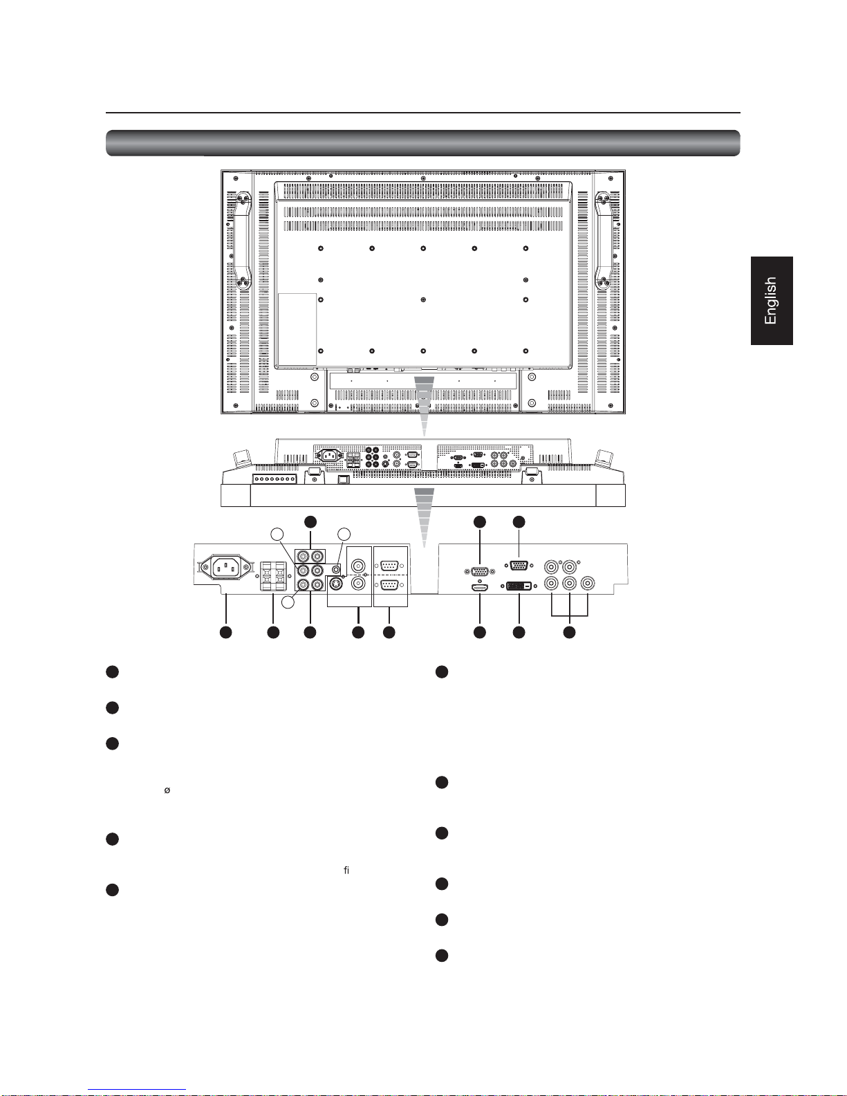
1 AC IN (3-pin, with earth terminal)
Connect s wit h the supplied power cord.
2 EXTERNAL SPEAKER TERMINAL
Con nects with the special stereo speaker s (option).
3
AUDIO IN
Co nnects with the audio output connec tor of external
equipment such as a comp uter, VCR, and DV D player.
(a) AUD IO1: 3.5 stereo mini-jack connector
(b) AUDIO2: RCA connector
(c) AUDIO3: RCA connector
4
AUDIO OUT (RCA)
Outputs the signal that is supplied to the selec ted AUDIO IN
co nnector. Connec ts with an external audio ampli er, etc.
5 VIDEO INPUT/OUTPUT (BNC/S c o nnec tor)
Connects with video equipment.
S VIDEO IN: S-video input connect or (MINI DIN 4 -pin)
VIDEO IN: BNC c onnec to r
VIDEO OUT: BNC connector
Conn ectors and Term inals
LR
a
c
b
IN
IN
OUT
OUT
RBG
Cr/Pr Cb/Pb
Y
HV
1 2 3
4
5 6 7
8
9
10
11
6 RS-232C connector (D-SUB 9-pin)
IN connector:
Co nnects with the RS-232C OUT connec to r of a computer or
other connected LDT323V.
OUT connector:
Co nnects with the RS-232C IN connec tor of other connected
LDT323V.
7 RGB1 IN (HDMI)
Co nnects with the digital video output of a c omputer, DVD
player, etc.
8 RGB OUT (MINI D- SUB 15- pin)
Outputs the signal that i s supplied to the RGB3 or RGB4 IN
connector.
9 RGB2 IN (DVI-D)
Connects w ith the digital v ideo output of a computer, etc.
10
RGB3 IN (MINI D-SUB 1 5-pin)
Connects wi th t he ana log video output of a computer, etc.
11
RGB4 IN, DVD/HD IN (BNC)
Conne cts w ith the a nalog video output of a computer or t he
component vi deo output of a DVD player, etc.
Parts Name and Functions (continued)
Page 11
Eng lish-10
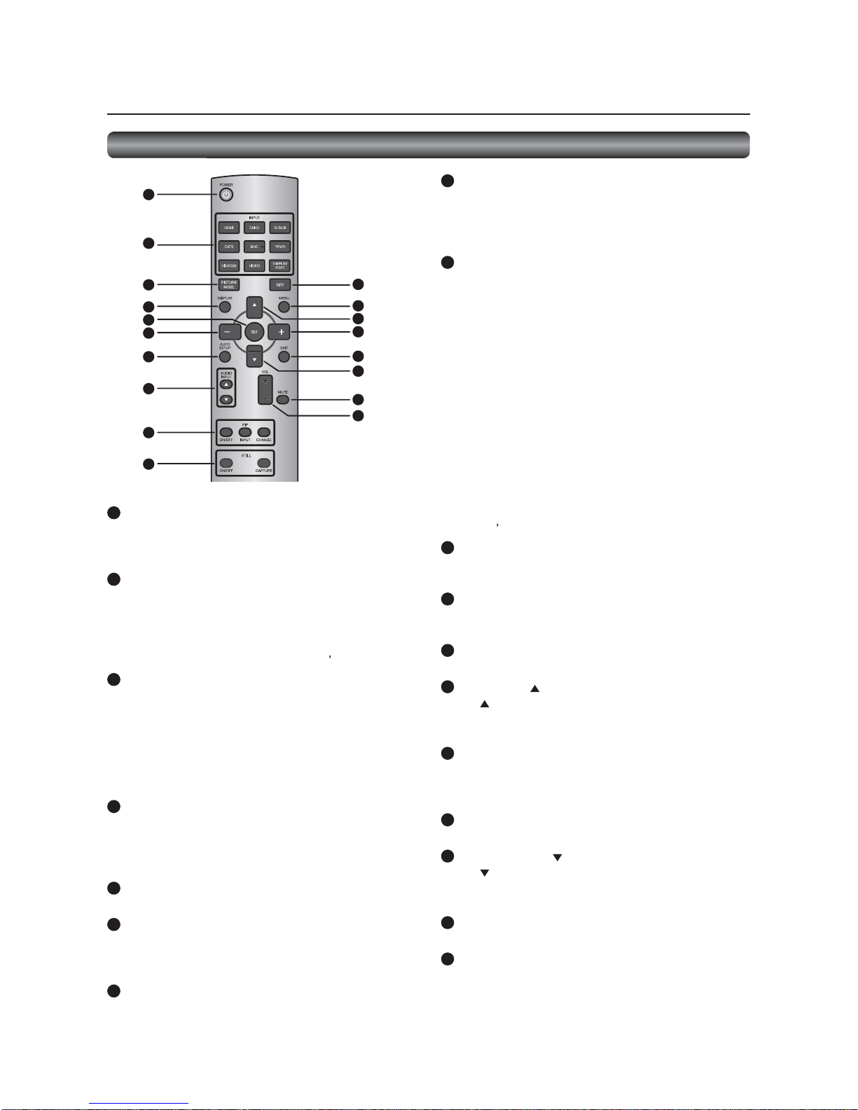
1 POWER butto n
Switches the power on/off.
* When the Power indic ato r is not glowing, no contro ls will
work.
2 IN P UT b u t t on s
Selec t the input signal from [RGB1] (HDMI), [RGB2] (DVI -D),
[RGB3] (D-SUB), [RGB4] (BNC), [DVD/HD] (YPbPr), [VIDEO<S>],
and [V IDEO].
NOTE:
The [CAT5] and [DISPLAY PORT] b utto ns do n t wo rk.
3 PICTUR E MODE b utto n
Selects the picture mode from [HIGHBRIGHT], [STANDA RD] ,
[sR GB], and [CINEMA]. See page 26.
HIGHBRI GHT: The brightness is maximized.
STANDARD: Factory default setting.
sRGB: Suitable for color matc hing with sRGB-
compliant devices .
CINEMA: Suitable for viewing movies.
4
DISPLAY b utto n
Displays the screen information. See page 42. When the remote
control mode is LOCK, you can set it back to NORMAL by
holding down the DISPLAY button for at least 5 seco nds (see
page 39).
5 SET button
Acc epts the settings made in the OSD menu.
6 MINUS button (-)
Acts as (-) button to decrease the adjustment in the OSD menu.
When the PIP mode is ac tive, this button moves the sub picture
to the left.
7
AUTO SETUP button
Displays t he auto setup menu. See pages 26 and 35.
8 AUDIO INPUT butto ns
Select the audio input from [AU DIO1], [AUDIO2], [AUDIO3], and
[HDMI]. Ho wever, note that [VIDEO<S>] and [VIDEO] use
common settings. Y ou can sel ect [HDMI ] only when the video
input source is [RGB1].
9 PIP (Picture-in-Picture) buttons
ON/OFF button: Switches the PIP or POP mode on/off.
INPUT button: Selects video to be displayed in the su b
pic ture.
CHANGE button: Changes the main picture with the sub
pic ture.
[Description]
PIP: Pictur e-in-Pictur e
The sub picture is di splayed wit hin the main picture.
POP: Picture-out-Picture
The sub pic ture is displayed to the bottom right of the main
pic ture.
SIDE B Y SIDE
The main picture and the sub picture are d isplayed si de by
side.
NOTE:
When the screen size is [C USTOM] or [REAL], the PIP and POP
modes don t work.
10
STILL button
ON/OFF button: Switc hes the s till pic ture mode on/o ff.
CAPTU RE button: Captures the new picture.
11
SIZ E button
Selects the picture size f rom [FULL], [NORMAL] , [CUSTOM],
[DYNAMIC], and [REAL]. See page 42.
12
MENU b utto n
Swit ches the OSD men u mode on/off.
13
UP button ( )
Acts as button to move the highlighted area up to selec t
an adjustment item in the OSD menu. When the PIP mode is
active, this button moves the sub picture up.
14
PLUS button (+)
A cts as (+) button to increase the adjustment in t he OSD men u.
When the PIP mode is ac tive, this button moves the sub picture
to the right.
15
EXIT b u tto n
Displays the previous OSD menu.
16
DOWN butto n ( )
Acts as butto n to move the highlighted area down to selec t
an adjustment item in the OSD menu. When the PIP mode is
active, this button moves the sub picture down.
17
MUTE b utto n
Switches the mute function on/off.
18
VO LU ME b ut t o n s ( VO L)
Pressing the plus (+) side inc reases the audio output level.
Pressing the minus (-) side decreases the audio output level.
Parts Name and Functions (continued)
Wireless Remote Control
1
2
3
4
5
6
7
8
9
10
11
12
13
14
15
16
17
18
Page 12
Eng lish-11
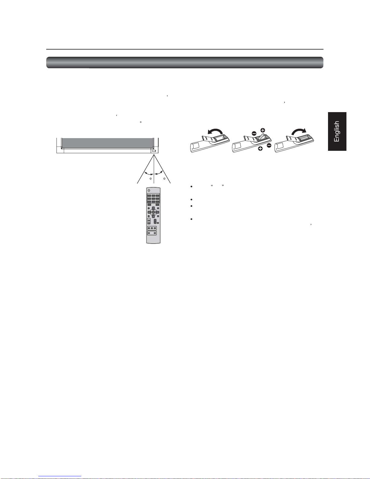
Op e ra ting Ra ng e o f th e Wire le s s Re mo te
Control
Point the wireless remo te control toward the LCD mo nitor s
remote c o ntro l sens or during b utto n o pe ratio n.
Use the wireless remote control within a distanc e of about 7 m
from the front of the LCD monitor s remote c ontrol sensor and
at a horizontal and vertical angle of withi n 30 within a distance
of about 3.5 m.
30 30
CAUTION:
The remot e control system may not function when direct
sunli ght or strong ill umination stri kes the remote control sensor
of the LCD monitor, or when there is an object in the path.
Handling the wireless remo te control
* Do not subject to strong shoc k.
* Do not allow water or other liquid to splash o n the wireless
remote c o ntrol. If the wire less remote c o ntrol gets wet, wipe
it dry immediately.
* Avoid ex posure to heat and steam.
* Other than to install the batteries, do not open the wireless
remote c o ntro l.
Parts Name and Functions (continued)
Ins tal ling th e Wire le s s re mot e c o nt ro l
batteries
The wirele ss remote c o ntro l is powered by 1.5 V AAA batte rie s.
1. Un lock and pull up th e cov er in the arrow s directi on.
2. Align th e batteries according t o the (+) and (-) indications
inside the case.
3. Replace the cover.
CAUTION:
Incorrect use of batteries can result in leaks or explosion.
Be careful especially about the following points.
Place AAA batteries m atching the (+) and (-) signs on each
battery to the (+) and (-) signs o f battery c ompartment.
Do not mix battery types.
Do not combine new batteries with used ones. It causes
shorter batter y li fe or leaka ge of batteries.
Remove dead ba tteries imm ediately t o prevent battery
liquid from leaking into the battery c ompartment. Do n t
touch exposed batt ery acid because it causes damage to
your skin.
NOTE:
If you do not use the wireless remote co ntrol for a long period,
remove the batteries.
How to Use the Wir eless Remote Con trol
Page 13

Eng lish-12
Flow of pr epar ation
P-1
Preparatio n for installatio n
- Determine the installation lo cation
- Ventilation requirements for enclosure mounting
Page 13
Carry ou t as necessary
P-2
P-3
P-4
P-5
Carry ou t as necessary
Installing the speakers
I nstalling the monitor
- Installing and r emoving the stands (Th e stands are optionally availa ble.)
- Installing the main switch cover
- Using the wall mo unt or c eiling mount
- Installing in the po rtrait po sition
Pages 14 to 15
Page 16
Pages 17 to 21
Page 22
Page 23
Conn ection procedure
- Wiring diagram
- Prevention of disconnection of HDMI cable
- Connecting with a computer (analog connection)
- Connecting with a computer (digital connection)
- Conn ecting a video device (componen t video/HD MI device)
- Conn ecting a video device ( composite video/S video device)/stereo ampli
er
Connecting the power cord to the monitor
- Co nnecting the power source
The mo nito r is ready fo r use.
How to Us e
Prepar ation for use
Page 14
Eng lish-13
P-1 Preparation for installation
This LCD has a temperature sensor and cooling fan. If the LCD
bec o mes hot, the co oling fan will turn o n auto matic ally. If the
LCD becomes overheated, the Caution menu will appear.
If the Caution menu appears, stop using the monitor and
all ow it t o cool. When the LCD monitor i s used in an enclosure
or with prot ection on LCD surface, please check the in side
temperatur e of the monitor by HEAT STATUS (See page 40). If
the temperature is higher than the normal level, set COOLING
FAN to ON using the SCREEN SAVER func tio n (See pag e 40).
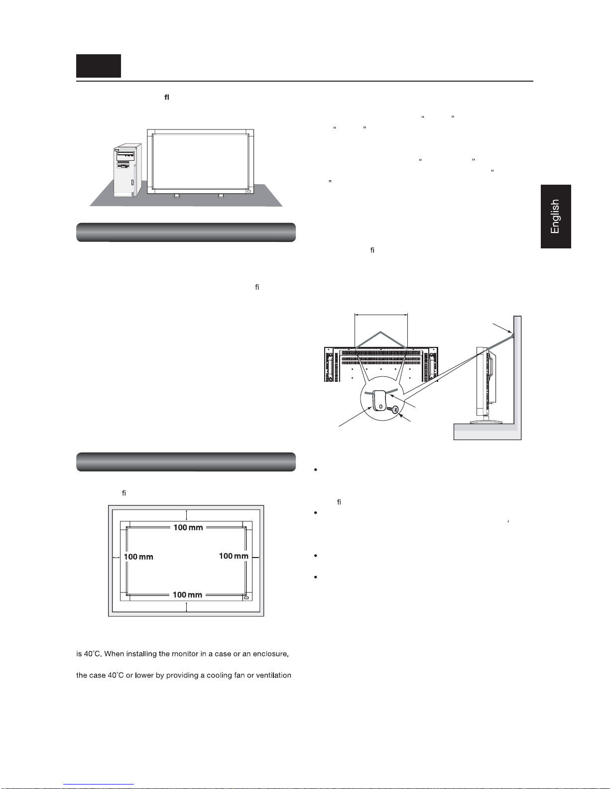
To avoid the monitor from falling
When installing the mo nitor using the tabletop stands (o ptional),
take measures to prevent the monitor from falling over in case
of an eart hquake or other disaster to lessen the p robability of
injury and damage r esulting from the fall.
As shown in the
gure, se c ure the monitor to a solid wall o r
pillar using rope (co mmercially available) strong eno ugh to bear
the weight of the monitor. [LDT323V: approximatel y 14.5 kg ( with
the optional stands)]
Use of screw hooks (with opening) i s recommended.
360 mm
CAUTION:
The effect of the fall prevention substa ntially depends
on the strength of brackets and base to which the fall
prevention dev ices is attached. When you cannot ensure
suf
cient strength, provide adequate reinfo rc ement.
Though the recommen ded fall prevention is intended to
lessen the probability of injury a nd dama ge, it doesn t
assure its effectiveness against any kind of earthquake or
disaster.
Do not sleep where the monitor may topple o ver or fall in
case of an earthquake or other disaster.
Befo re moving the mo nitor, remo ve the rope that is
securing the monitor. Failure to do so may result in injury or
breakdown of the monitor.
Screw holes
Screw hook, etc.
commercial ly available
Clam per
Screw
Rope, etc.
co mmerc ially
available
Install the mo nito r o n a at, level, stable surface where the
screen is easy to view.
(For install ation using the option stand.)
Determine the installation location
CAUTION:
DO NOT ATTEMPT TO INSTALL THE LCD MONITOR BY
YOURSELF .
Installing your LCD monitor must be done by a quali
ed
technician. Contact your dealer for more information.
CAUTION:
MOVING OR INSTALLING THE LCD MONITOR MUST BE
DONE BY TWO OR MORE PEOPLE.
Failure to follow this c aution may result in injury if the LCD
monitor falls.
CAUTION:
Do no t mount or operate the mo nitor upside do wn, fac e up, or
face down.
IMPORTANT:
Lay the protective sheet , wh ich was wrapped around the LCD
m onitor when it was packaged, ben eath th e LCD monitor so as
not to scratc h the panel.
Vent ilation requirem ents for enclosu re mounting
To allow heat t o disperse, leave space around the moni tor as
sh own in the
gu re below .
CAUTION:
The upper limit of the operation guaranteed tem perature range
ensure adequate ventilation to keep the temperature inside
holes in the case.
Page 15
Eng lish-14
P-2 Installing the monitor
Car ry out as necessary
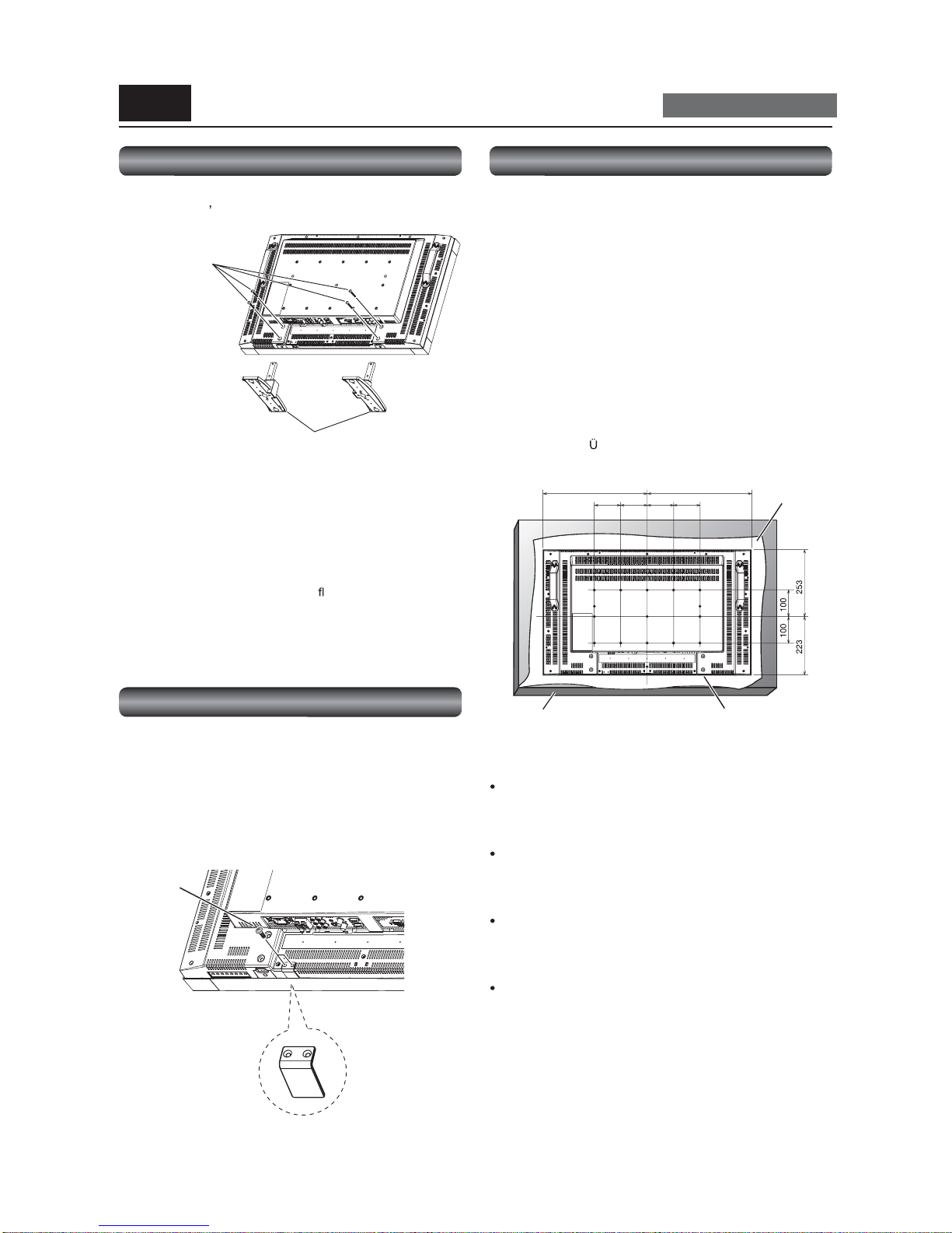
I nstalling and removing the stands
The stands are a vai lable as option.
Refer to the user s manual of the stand for more informat ion.
How to install th e stands
1. Turn the monitor off.
2. Fasten screws on both s ides of the monitor.
NOTE:
Install the stands so that their longer portions come to the front.
How to re mo ve the s tands
1. Spread th e protective sheet on a
at surface, such as a
desk.
2. Plac e the monitor on the protective sheet.
3. Re mo ve the screws with a sc re wdrive r and plac e them in a
safe place for reuse.
I nstalling the main switc h cover
T o prevent unautho rized operatio n of the main power switc h,
attach the ma in switch cover, which is supplied as an
accessory.
NOTE:
With the main power switch cover in pl ace, the main power
swi tch cannot be turned off. Remove t he main power switch
cove r in o rde r to s witch o ff the mo nitor.
Screw x 4
( Accessor ies of
the option stand)
Opti on stand x 2
(Longer portion c omes to the front.)
Screw x 2
(Acc esso ry)
Main switch cover
(Acc esso ry)
Using the wall mount or ceiling mount
Lay the screen face down
Lay the protective sheet on a table, which was wrapped around
the monitor when it was packaged, beneath the screen surface
so as not to scratch the screen surface.
This devic e c annot be used o r installed without the Tabletop
Stand or other mounting ac cesso ry. Failure to follow the c orrec t
mounting procedures can result in damage to the equipment or
injury to the user or inst a ller. Pr oduct warranty does not cover
damage caused by improper installation.
Failure to follow these reco mmendations can vo id your
warranty .
Use M6 screws (having a length 10 mm l onger t han t he
thickness of the mo unting bracket) and tighten them securely.
Prevent the screw s from loosening using spring washers, etc.
MITSUBISHI ELE CTRIC recommends using mounting interfac e
that comply w ith T V-GS and/or UL1678 standar d in North
America.
394.5 394.5
100 100 100 100
CAUTION:
For preventing the monitor from falling.
Install the monitor with metal brackets fo r wall or
ceiling installation (commercially available) on y our own
responsibility. For detailed pro c edure s o f installatio n, re fer
to the instructions of the metal brackets.
To lessen the probability of inj ury and damage result ing
fro m fall o f the monitor in case of earthquake o r other
disaster, be sure to consult the bracket manufacturer for
installatio n loc ation.
To lessen the risk of falling of t he monitor, thread
commercially available rope through the handles at the
right and left of the mo nitor and sec ure the ro pe to the wall
mount brackets or ceiling mount brac kets.
Do not sleep where the monitor may topple o ver or fall in
case of an earthquake or other disaster.
Protective
Sheet
Tab le to p S tand
(mm)
Tab le
Page 16

Eng lish-15
I nstalling in the portrait position
Conditions:
LDT323V can be installed in the po rtrait po sition, under the
following c onditions:
CAUTION:
Portrait position is available o nly when the monitor is wallmounted or ceiling-mounted.
The stands (legs) can not be
tted to the monitor in the portrait
position.
Plac ing the monitor in the po rtrait position will shorten the
average life of the LCD backlight.
Operation Environment (Temperature) shall be limited, as
shown bel ow:
Operation En v ironment:
Temperat ure 5 - 35 C / 41 - 95 F
Humidity 20 - 80% (without condensation)
Plac e the monitor in the po sition shown below.
Do not place the monitor in landscape in an y oth er manner than
shown.
Optional spea kers can not be attached w hen the LCD monitor
is installed in the po rtrait position.
How to se t-up
The
logo shoul d be on the LEFT side when
viewed from the front o f the monitor.
90 Clockwise
logo
P-2 Installing the monitor (continued)
Car ry out as necessary
Landsc ape
Page 17

Eng lish-16
To s p e ake r t e rmina l ( L) To s pe aker te rminal (R)
Red(+)/ Blac k(-) Red(+)/ Blac k(-)
SPEAKER (S)(L)
SPEAKER (S)(R)
NOTE:
The speaker cord has polarity (+ and -). Match the colo rs of the speaker terminal and the c onnec tor of the c ord.
CAUTION:
Do not move the mo nitor with the speakers installed.
The monitor and the speakers may be damaged and you may be injured if the monitor falls.
Left s peaker Right speaker
Before connecting the signal cable to PC and Video
Optional speakers c an be installed.
Please refer to user s guide o f the optional speakers for the detailed installation procedure.
How to install the optional speakers
1 . Use the m etal
ttings and screw s that are supplied with the option speakers.
2. Co nnect the cord of the left speaker to the SPEAKER (S) terminal (L) on the monitor, and the c ord of the right speaker to the
SPEAKE R ( S ) ter min a l (R ).
P-3 Insta lling the speakers
Car ry out as necessary
Page 18

Eng lish-17
Pre vention of disconnection of HDMI cable
The HDMI cable must be s ecured by t he clampe r to prevent it from being disconnected accidentally.
RBG
HV
DVI IN
D-SUB IN
D-SUB OUT
HDMI
RS-232C IN
RS-232C OUT
VIDEO IN
VIDEO OUT
S-VIDEO
IN1
IN2
IN3
OUT
R
L
Computer
(DVI-D, HDMI)
Computer
(Analog RGB)
LCD mo nito r (rear)
LCD monitor (sec ond monitor)
DVD player (HDMI, BNC)
HD disk player (H DMI)
VCR (RCA)
Stereo ampli
er
Exte rnal speakers
Clamper
(Acc esso ry)
Ca ble Hold er (Accessory)
Before making c onnections
First turn off the power of all the connected equipment before making connections.
Refer to the user manual of each piece of equipment.
NOTE:
Please use the audio cable without resistance when the audio o utput terminal of the audio device and PC is stereo mini-Jac k.
When the audio cable with resistance is used, the audio level may not be increased or no audio may be output.
Wiring diagram
P-4 Connection procedure
LCD mo nito r ( rst mo nito r)
Page 19

Eng lish-18
RGB cable
(Mini D-SUB 15-pin to
Mini D-SUB 15-pin)
To aud io o utp u t
To BNC o u t p ut
Audio c able
( 3.5 mm stereo mi ni)
RGB3 IN (D-SUB)
AUDIO IN2 (RCA)
RGB cable
(Mini D-SUB 15-pin to
Mini D-SUB 15-pin)
RCA cable (audio)
To D- SUB o ut p ut
LCD mo nito r (rear)
LCD monitor (sec ond monitor)
(Multi-connec tion)
Computer
(Analog RGB)
Computer
(Analog RGB)
LCD mo nito r ( rst mo nito r)
Connecting with a computer (analog connection)
Analo g connection:
Connection via RGB3 IN (D-SUB) connector
(1) Connect an RGB c able (mini D-SUB 15- pin mini D- SUB 15-pin) (acce ssory) to the RGB3 IN conne ctor.
(2) Select [RGB3] using the INPUT button on the monito r or the D- SUB button on the wireless remote c ontrol.
Connection via RGB 4 IN (BNC: R G B H V, or R G B Csync, RGB sync on green) connector
(1) Use a BN C cable (BNC x 5 - BN C x 5) (commercially available) to connect the BNC connector on the PC, and use a signal
cable (mini D-SUB 15-pin - BNC x 5) (commercially available) to conn ect the mi ni D-SUB 15-pi n connector on the PC.
(2) Select [RGB4] using the INPUT button on the monito r or the BNC button o n the wireless remote c ontrol.
Second monitor connection:
Connect the RGB OUT connector (mini D-SUB 15-pin) on the
rst monitor and the RGB3 IN connec tor (mini D-SUB 15- pin)
on the second monitor using an RGB cable (mini D-SUB 15-pin - mini D-SUB 15-pin) (an ac cessory of the sec ond monitor or
commercially availab le).
(The RGB3 or RGB4 signal selected by the
rst monitor is output. The RGB1 or RGB2 signal isn t output.)
NOTE:
When different monitors need to be adjusted so that their t int can be identical, su ch as w hen using mul tipl e screens, it is
rec o mmende d to us e a signal dis tributo r (c ommercially available).
Audio connecti on:
Connect an audi o cable ( 3.5 mm stereo mini) (commercially available) to t he AUDIO IN1 connector.
Selec t [AUDIO1] using the AUDIO INPUT buttons on the wireless remote c ontrol.
T o o utput audio to the second monitor:
Connect the AUDIO OUT connector on the rst monitor and the AUDIO I N2 o r 3 c onnec tor on the seco nd mo nitor using an RCA
cable (audio) (c ommerc ially available).
P-4 Connection procedure (continued)
Page 20

Eng lish-19
DVI-D c ab le
HDMI cable
T o DVI-D output
To HDMI o utp u t
To Aud i o o u t p ut
Audio c able
( 3.5 mm stereo m ini)
Computer
(DVI-D, HDMI)
LCD monito r
Connecting with a computer ( digital connection)
Digital connectio n:
Connection via the RGB1 I N connector (HDMI)
(1) Connec t an HDMI cable (c ommerc ially available) to the RGB1 IN connec tor.
(2) Select [RGB1] using the INPUT button on t he monitor or the H DMI button on t he wireless rem ote control.
Connection via the RGB2 IN connector ( DVI-D)
(1) Connec t a DVI-D c able (commerc ially available) to the RGB2 IN connector.
(2) Select [RGB2] using the IN PUT but ton on the monitor or t he D VI-D button on the wireless rem ot e control.
Audio connecti on:
Conn ect an audio cable ( 3.5 mm stereo mini) (co
mmerc ially available) to the AUDI O IN1 connecto r.
Select [AUDIO1] using the AUDIO INPUT butto ns on the wireless remote c ontrol.
When an HDMI cable is connected, select HDMI audio.
(You can select HDMI only when the video input is [RGB1].)
LCD monito r (re ar)
P-4 Connection procedure (continued)
The monitor automatic ally distinguishes the timings shown in the table below and sets the sc reen informatio n. When a PC or other
devic e is connected, it auto matically displays images properly.
<Factory pr eset timi ng>
Resoluti on
Fr equency
Remarks Resoluti on
Fr equency
Remarks
H ori zontal V ertical H ori zontal V ertical
1 640 x 480 31 .5 kHz 60 Hz 6 1280 x 1024 64.0 kHz 60 Hz
2 800 x 600 37.9 k Hz 60 Hz 7 1600 x 1200 75.0 kHz 60 Hz
3 1024 x 768 48.4 kHz 60 Hz 8 1920 x 1080 67.5 kHz 60 Hz
4 1280 x 768 47.8 kHz 60 Hz 9 1920 x 1200 74.0 kHz 60 Hz CVT Reduced Bla nking
5 1360 x 768 47.7 kHz 60 Hz Recommend timing
NOTE:
When a signal other than 1
x is input, characters may be blurred and gures and objects may be distorted.
Images may not be displ ay ed correctly depending on the video card or driver bei ng used.
Page 21

Eng lish-20
BNC-RCA adaptor
HDMI cable
DVD/HD IN
(Y Pb Pr, Y Cb Cr)
AUDIO IN2 (RCA)
RG B1 IN (HDMI)
T o D connec to r o utput
To vid e o o ut p ut
To HDMI o utp u t
To Au dio o utp ut
RCA cable (audio)
Signal cable
(BNC x 3 to D connec to r)
BNC cable
(BNC x 3 to BNC x 3)
RBG
HV
DVI IN
D-SUB IN
D-SUB OUT
HDMI
RS-232C IN
RS-232C OUT
VIDEO IN
VIDEO OUT
S-VIDEO
IN1
IN2
IN3
OUT
R
L
Connectin g a video device ( component video/HDMI device)
This monitor c an be connec ted to a video device e quipped with component output such as a DVD player.
Refer to the user s manual of the connected devic e for details. (Cables sho wn in the gure below are commercially available.)
To c onnect a DVD player equipped with component output to the DVD/HD IN connec tor (YPbPr or YCbCr) on the mo nitor, use a
BNC cable (BNC x 3 BNC x 3) and a BNC-RCA adaptor (commercially av ailable), or a signal cable (BNC x 3 D connector).
Select [DVD/HD] using the INPUT button on t he mon itor or the YPbPr button on the wireless remote control.
T o make audio c onnec tion, connect an RCA c able (audio) to the AUDIO IN2 connector or the AUDIO IN3 co nnecto r.
Se lec t [AUDIO2] o r [AUDIO3] using the AUDIO INPUT butto ns o n the wire le s s re mo te c o ntro l.
T o c onnec t a DVD player equipped with HDMI output to the RGB1 IN co nnec tor (HDMI) on the monitor, use an HDMI signal
cable.
Select [RGB 1] us ing the INPUT but ton on the moni tor or the HDMI button on the wireless rem o te control.
For HDMI cable connecti on, select HDMI audi o.
(You can select H DMI audio only when the video in put is [RGB1].)
DVD player
(compo nent device)
LCD monito r (re ar)
DVD player
(HDMI devic e)
P-4 Connection procedure (continued)
Page 22

Eng lish-21
S-VIDEO IN AUDIO IN2
AUDIO OUT VIDEO IN
VIDEO OUT
VIDEO IN
RCA cable (audio)
S video cable
BNC cable
RBG
HV
DVI IN
D-SUB IN
D-SUB OUT
HDMI
RS-232C IN
RS-232C OUT
VIDEO IN
VIDEO OUT
S-VIDEO
IN1
IN2
IN3
OUT
R
L
Connecting a video device (composite video/S video device)/stereo ampli er
This monitor can be connec ted to a stereo ampli er.
Refer to the user s manual of the stereo ampli er fo r details. (Cables shown in the gure below are co mmerc ially available.)
T o c onnec t a video devic e to the VIDEO IN connec tor (VI DEO IN or S-VIDEO IN) on the monitor, use a BNC c able or an S video
cable. For connection to the audio i nput connect or on the m onit or, u se a n RCA cable (audio cable). Connect the connectors
of the RCA cable (audio) co rrectly. For connec tion to the VIDEO IN co nnecto r, select [VIDEO] using the INPUT button on the
monitor or the VIDEO button on the wireless remote c ontrol. For connection to the S-VIDEO IN connec tor, selec t [VIDEO<S>]
using the INPUT bu tton on the monitor or the VI DEO(S) bu tton on t he wi reless remote control.
T o c onnec t two mo nitors, connect o ne end of a BNC cable to the VIDEO OUT connec tor of the
rst mo nitor and the other end to
the VIDEO IN connec tor of the sec ond monitor.
NOTE:
When different monitors need to be adjusted so that their t int can be identical, su ch as w hen using mul tipl e screens, it is
rec o mmende d to us e a signal dis tributo r (c ommercially available).
Wh en connecting a stereo ampli
er to the monito r, be sure to turn off the power of the stereo ampli er. For connec tion to the
audio output c onnec tor on the mo nitor , use an RCA cable (audio). Connec t the c onnec tors of the RCA cable (audio) co rrectly. Be
sure to turn on the monitor rst, and then turn on the stereo ampli er.
The selected audio input signal is output from the AUDIO OUT connector.
LCD mo nito r ( rst mo nito r)
LCD monitor (sec ond monitor)
LCD mo nito r (rear)
Stereo ampli
er
External speaker External speaker
Video device
(composite video/S video device)
P-4 Connection procedure (continued)
Page 23

Eng lish-22
Connecting the power source
The power outlet socket should be installed as near the equipment as possible an d shou ld be easily accessible.
Fully insert the prongs into the powe r outlet soc ket.
Loose connection may cause noise.
NOTE:
Please refer to Safety Prec autions, Maintenance & Recommended Use in this manual for proper selection of the AC power cord.
P-5
Connecting the power cord to the monitor
Use the cl amper to secure the
ca ble
rmly.
Clamper (Accessory)
Cable holder
(Acc esso ry)
Power cord
Page 24

Eng lish-23
Flow of How to Using
U-1
U-2
U-3
U-4
U-5
U-6
U-7
U-8
U-9
U-10
Carry ou t as necessary
Page 24
Page 25
Page 26
Page 26
Page 27
Page 26
Page 27
Page 28
Pages 28 to 29
Pages 30 to 31
Turning on all the co nnected devices
Selecting the video input
Controlling the ext ernal devices
RGB3 and RGB4 only
Auto -setup
Selecting the picture mo de
Screen ad justment
Picture adjustment
Vo lum e c o ntro l
Sc hedule setting
Remote c ontrol
How to Use
Page 25

Eng lish-24
U-1 Turning on all the connected devices
Wireless remote
control
Power Indicator
Status LED
Power ON Gr een
Power OF F Red
Power Standby when
SCHEDULE is enable
Red On
Gr een Blinking
Sleep mode Red, Green
Diagnosis (Detecting failure) Red Blinking
* See trou b lesh ooting on page 44.
Turning o n e xternal d e vic e s
1. Turn on th e connect ed devices such as
the computer and VCR.
Turning o n the mo nito r
2. Turn on the Main Power Switch.
The power indic ator turns o n green.
The control but tons on the b ottom o f the monitor a nd the
wireless remote c o ntro l do n t wo rk while the Main Powe r
Switc h is off (the power indicator is off).
When using them, check that the M ain Power Switch is on
(the power i ndicator is on).
3. When the p ower indicator gl ow s
red, press the POWER button on the
monit or.
The powe r indic ator turns green.
Power Management Function
This function reduc es the power consumption of the monitor
when the keyboard or the mouse is not used for a
xed period
even though the power of the mon itor is on.
While this function is working, the sc reen becomes dark and
the power indicator glows green and red.
T his functi on is avail able only when a computer equipped
with the VESA-approved DPM Power Management func tion is
co nnected to the monitor.
When the power saver in the OSD menu is turned ON, the
power management function works.
RGB: When the sync signa l of computer i nput (RG B1, 2, 3, or
4) is terminated, the monitor will be in the sleep mode
in several sec onds.
VI DEO: When the sync signal of video input (DVD/HD,
VIDEO<S>, or VIDEO) is terminated, the monit or will be
i n the sl eep mode in approximatel y 10 mi nutes.
[Description]
DPM: Ac ronym for Display Power Management
NOTE:
The def ault power management settin gs (power saver s) for
RGB and VIDEO ar e ON.
Power button
Power button
Main Power Switch
or
Page 26

Eng lish-25
You c an se lect the desired video input us ing the wire less re mo te c ontrol or the INPUT button on the mo nitor.
1. Selec t using the INPUT buttons on the wireless remote control.
You c an select the de sired video input by pressing the c orresponding INPUT button on the wire less remote c o ntrol.
Selectable video inputs are [RG B1] (HDMI), [ RGB2] (DVI-D), [RGB3] (D-SUB), [RGB4] (BNC), [DVD/HD] (YPbPr), [ VIDEO<S>], and
[V IDE O ] .
NOTE:
The [CAT5] and [DISPLAY PORT] b utto ns do n t wo rk.
2. Select using the INPUT button on the monitor.
When y ou press the INPUT button on the m oni tor, the video input OSD menu is displayed and you can select the video inpu t
using the
and buttons.
Selec table video inputs are [RGB1] (HDMI), [RGB2] (DVI- D), [RGB3] (D-SUB), [RGB4] (BNC), [DVD/HD] (YPbPr), [VIDE O-S], and
[V IDE O ] .
NOTE:
The selection you make do esn t c omplete unless yo u press the INPUT butto n while the OSD information is displayed. See page 39.
RGB1
RGB2
RGB3
RGB4
DVD/HD
VIDEO-S
VIDEO
U-2 Select ing the video input
INPUT butto n
Video input OSD menu
Select using the
and buttons.
Page 27

Eng lish-26
You can control the exter nally connected devices t o displ ay images supplied from them.
U-4 Auto-setup
Analog inputs only
T he A UTO SETUP but ton on the wireless remote control or AUTO SETUP in the OSD men u automatically adjusts the screen size,
horizo ntal/vertical po sition, clo c k, c lock phase, white level, and black level.
NOTE:
The auto setup works on RGB3 and RGB4 only.
U-5 Selecting the picture mode
Using the PICTURE MODE butto n on the wireless remote c ontrol, you can select the picture mode suitable for images to be
displayed.
HIGHBRIGHT: The bri ght ness is maximized.
STANDARD: Factory defa ult setting.
sRGB: Suit able for color matching with sRGB-compl iant devi ces.
CINEMA: Suitable for viewing movies.
U-3 Controlling the exter nal devices
VCR, e tc .
Personal computer
Page 28

Eng lish-27
Wh en images aren t di sp layed properly even after the auto setup, you can alternatively adjust the screen by pressing t he M ENU
button on the w ireless rem ote control or the control buttons on the bottom of the monitor to d isplay the OSD menu. Using the
SCREE N settings in the O SD menu, you can adjust the h ori zontal/verti cal position, cl ock, clock pha se, CUSTO M ZOOM, horizontal
resolution, vertic al resolution, and input res olutio n.
NOTE:
T he position adj ustment wor ks on RG B3, RGB4, DVD/HD, VIDEO<S>, and VIDEO only.
The clock adjustm ent and th e resolution adjustment work on RGB3 and RGB4 only.
The zoom adjustment works on all video inputs.
U-7 Picture adjustment
You c an adjust the picture by pressing the MENU button on the wireless remote c ontrol or the control buttons on the bottom of
the monitor to display the OSD menu. Using the PICTURE settings in the OSD menu, you can adjust picture settings such as the
brightness, contrast , and sharpness.
U-6 Screen adjustment
Page 29

Eng lish-28
Wh en output ti ng audio from the option stereo speakers, you can control the vol ume level using the VOL button on the wireless
remote c o ntro l.
In addition, you can adjust the volu me by pressing the M ENU button on the wirel ess remote control or the control bu ttons on the
bottom of the mon itor to display the OSD men u. U sing the AUDIO settings in the OSD menu, you can adjust the balance, treble, and
bass.
U-9 Schedule setting
Car ry out as necessary
You can program the po wer-on/off and input selec tion using the SCHEDULE setting in the OSD menu that is displayed by pressing
the MENU button o n the wireless remote co ntrol o r the control buttons on the bottom of the mo nitor .
U-8 Vo lume c o ntro l
Car ry out as necessary
Vo lume
control
Displaying
the OSD
menu
or
Page 30

English-29
When the cursor i s on any of the check boxes showing the program nu mbers 1 to 7 on th e left side of the screen, pressing the UP
(
) or DOWN ( ) butt on moves the cursor v ertically a nd pressing the PLUS (+) or M INUS (-) buttons moves it horiz ontally.
By pressing the SET button, you can select or deselec t the chec k boxes.
Check box: When the check box is selected, the program is enabled. Whe n it is clea red, the progra m is disabled.
Wh en the SCHEDULE scr een is closed, the programs you made become enabled and will be executed at the
speci
ed times.
When the cursor i s on any item of the schedule settings in the white fr ame, pressing the PLUS (+) button mov es it to the right and
pr essing the M INUS ( -) but ton moves it to the left.
You can set the power-on/off time and video input by pressing the UP (
) or DOWN ( ) button. You can select or deselect the
radio buttons by pressing the SET button.
ON: Set the time when the power is turned on. If you do n t want to set the power-on time, enter --.
OFF: Set the time when the power is turned off. If you do n t want to set to the power-off time, enter --.
INPUT: Set the video input to be selected when the power is turned on. If you want to select the vide input that was
selected before t he power is turned on, enter --.
E VERY DAY : Select this option t o execute the schedul e ev ery day. When you sel ect EVERY DAY, you cannot sel ect any da ys
of the week and EVERY WEEK.
MON - SUN: Select the days of the week on which you want to execute the sc hedule. Unless you selec t EVERY WEEK, too,
the select ion of the days of the week is cleared aft er the schedule is executed one time.
E VERY WEEK: Select t his option to execute th e schedul e on the selected days of the week, every week.
NOTE:
Before making the schedule settings, be sure to c heck the c urrent date and time using DATE AN D TIM E.
When you close the SCHEDULE screen, the settings a re saved.
When two or mor e schedules are ena bled, they are executed in descending order of the program number, and the power is
turned off u pon completion of t he la st executed schedule.
Wh en there are two or more schedules having the same power-on/ off time, the one having the largest p rogram num ber is
executed.
You cannot set the power-on time and the power-off time to the same time.
Wh en OFF TIMER is ON, the schedule settings are ign ored.
Check box
Radio button
U-9 Schedule setting (continued)
Car ry out as necessary
Page 31

Eng lish- 30
To RS- 23 2 C
connector IN
RS-232C cable
(co mmerc ially available)
RS-232C cable
(co mmerc ially available)
PC
To RS-232C
connector IN
To RS-232C
connector OUT
U-10 Remot e contr ol
Car ry out as necessary
RS-232C Remote control
By c onnec ting multiple LCD monito rs and a c omputer using RS-232C cables (commerc ially available), you c an co ntrol the monitors
from the computer for the following operations:
Power ON or OFF
Switc hing between input signals
Volume control and mute
Auto s etup
Check of the internal temperature of the monito r, etc.
Connection
Before making co nnec tio ns, turn o ff the pe rsonal c omputer and the monito rs.
NOTE:
For connection with a 25-pin serial port connector on the computer, a conversion adapter (commercially available) is required.
1) Interface
PROT OCOL RS-232C
BAUD RATE 9600 [bps]
DAT A LE NGTH 8 [bit]
PARITY BIT NONE
STOP BIT 1 [bit]
FLOW CONTROL NONE
This LCD monitor uses RXD, TXD and GND lines for RS-232C co ntrol.
Use RS-232C cables of reverse type (c ommercially available).
2) Contr ol command diagram
Th e command is structured by th e address code, function code, data code and end code. The length of the command is
different for each fu nct ion.
NOTE:
This example shows a basic command that is used when a single computer and a singl e monitor are connected.
When you want to connect multiple monitors or perform complicated c ontrol using other commands than the basic
commands, contac t your dealer for advanced c ommand speci
cations.
To use terminal software, send a text
le with control commands. The monitor is not compatible with the sending of
commands using a keypad.
Address code Function code Data code End code
HEX 30h 30h Func tio n Data 0Dh
ASCII 0 0 Function Data
[ Addr ess code] 30h 30h (ASCII code, 0 0 ), xed.
[Function code] Code unique to each control function.
[Data code] Data unique to each c ontrol func tion (Not always indicated by numerical values.)
[End c ode] 0Dh (In ASCII code,
) xed.
LCD monitor (sec ond monitor)LCD mo nito r ( rst mo nito r)
Page 32

Eng lish- 31
3) Control sequence
(1) A command is sent f rom the computer to the monit or. (Commands should be sent at intervals of at least 600 ms.)
(2) Th e monitor sends a return command within 600 ms* after receiving and encoding t he command. If the monitor fails to
rec eive the c o mmand, it doesn t send any return c ommand.
(3) The computer checks th e return comm and to see that the command it sent was executed or not.
(4) The monitor sends various c o des o ther than the return c o de. While RS-232C contro l sequenc e is in pro gress , rejec t othe r
codes on the personal computer side.
*: Tran smission of the r e turn command may be delayed during signal switchover, etc.
Exam ple: Turn the power ON ( is for ASCII code)
Command from computer Command from monitor Detail of command
30 30 21 0D
0 0 !
Command for POWER ON
30 30 21 0D
0 0 !
Command received
(Command echoed back)
4) Operation commands
The operation commands con
gure the basic operation settings of this LCD monitor. The commands may not work during signal
switchove r.
The operation commands have no data codes.
Operation ASCII HEX Operation ASCII HEX
POWER ON ! 21h INPUT DVD/HD _v2 5Fh 76h 32h
POWER OFF " 22h INPUT S-VIDEO _v3 5Fh 76h 33h
INPUT RGB 1 _r1 5Fh 72h 31 h VO LUME UP r06 72h 30h 36h
INPUT RGB 2 _r2 5Fh 72h 32h V O LUME DOWN r07 72h 30h 37h
INPUT RGB 3 _r3 5Fh 72h 33h MUT E ra6 72h 61h 36h
INPUT RGB 4 _r4 5Fh 72h 3 4h AU TO SETUP r09 72h 30h 39h
INPUT VIDEO _v1 5Fh 76h 31h
When y ou send the POWER ON or POWER OFF command, send the next command at intervals of at least seven seconds.
When you send each INPUT switch command, send the next command at in terval s of at l east ve seconds.
In the power off m ode or the sleep mode, onl y the POWER ON, POWER OFF, and P OWER ON read command which is
descr ibed on the next page can be operated.
5) Read command
The computer sends the command witho ut dataco de to the monitor.
After rec eiving this c ommand, the mo nitor returns the c ommand with datac ode including the c urrent status to the co mputer .
E xample: When t he computer asks the power status of th e monitor, and th e status of the monitor is powered-on.
Command from computer Command from monitor Detail of c ommand
30 30 76 50 0D 0 0 v P [enter ] Ask about the power stat us of the monitor.
30 30 7 6 5 0 31 0D 0 0 v P 1 [enter] Monitor is powered-on.
Structure of the Rea d-command
ASCII HEX
Function Data (Receive) F unction Data (Receive)
POWE R
ON vP 1 76 50 31
OFF (Sleep) vP 0 76 50 30
Input
RGB -1 (HDMI) vI r 1 76 49 72 31
RGB -2 ( DVI-D) vI r2 76 49 72 32
RGB -3 (D-SUB) vI r3 76 49 72 33
RGB -4 (B NC) vI r4 76 49 72 34
V ideo v I v1 76 49 76 31
DVD/HD vI v2 76 49 76 32
S-VIDEO vI v3 76 49 76 33
Inte rnal
temperature
Around the main
board
Resoluti on
tc1 (ex.) +25 74 63 3 1 2B 20 32 35
Around the power
supply
Resoluti on
tc2 (ex.) + 31 74 63 32 2B 20 33 31
U-10 Remote control (continued)
Car ry out as necessary
Page 33

Eng lish- 32
Adjustment sta tus
The values adjusted by the wireless remote control and the
PLUS and MINUS buttons on the monitor are displayed.
Sub men u (Adjust ment items )
Adju stment items are displayed .
Operation buttons (Key guide)
Buttons for controlling the displayed OSD menu are displayed.
PICTURE
SCREEN
AUDIO
PIP
CONFIGURATION1
CONFIGURATION2
CONFIGURATION3
ADVAN CED OPTI ON
Main menu
Icons other than the one y ou selected are grayed out.
Sub menu screen
When y ou sele ct a sub menu, an O SD screen is di spla yed.
Sub menus contain information sc reens, adjustment menu screens, and selection menu screens as shown below.
Sub menu s c ree n: Pic ture reset (for e xample)
Page 34
Page 35
Page 36
Page 37
Page 38
Page 39
Page 40
Page 41
Con guration of OS D screen
T his monit or is equipped with t he OSD (On Screen Display) function for easy screen adjustment. The O SD function allows you to
control the menus displayed on the sc reen for brightness setting and other settings.
The OSD scr een is con
gu red as shown below.
Main Menu Screen
Con guration and bas ic operation of OSD scre en
Page 34

Eng lish- 33
Basic operation of OS D
When the ME NU button on the wireless remote c ontrol or the EXIT button on the monitor is pressed, the OSD screen is displayed.
Selec t a main menu by pressing the
or button.
Accept the se lected main menu
by pressing the SET button.
Accept the se lected main menu
by pressing the IN PUT button.
INPUT butto n
but ton
INPUT butto n
INPUT butto n
but ton
Select a sub menu by pressing
the or button.
Select a sub menu by pressing
the or button.
Accept the selected sub menu
by pressing the SET button.
Accept the selected sub menu
by pressing the IN PUT button.
Selec t the setting value by
pressing the
or button
and then press the SET button
to ac cept the setting.
Selec t the setting value by
pressing the or button and
then press the INPUT butto n to
a ccept the setti ng.
The OS D screen disappea rs when you press th e MENU button on the wireless remote control once or the EXIT button on the
mo nito r three times.
Wireless remote c o ntro l Monito r butto n OSD sc reen
Con guration and b asic operation of OSD screen (continued)
Page 35

Eng lish- 34
OSD screen functions
BRIGHTNESS
You c an adjust the brightness.
Press the PLUS (+) bu tton to increase t he brightness. Press
the MINU S (-) button to decrease the brightness.
CONTRAST
You c an adjust the contrast.
Adjust the contr ast using the PLUS (+) or MINUS (-) button
to o btain a desired result.
NOTE : Brightness changes luminance of the bac klight.
Co ntrast changes signal levels, and therefore it is
likely to lead to whiteness.
SHARPNESS
You c an adjust the sharpness.
Press the PLUS (+) button to make the image look sharper .
Press the MINUS (-) button to make the image lo ok softer.
NO TE : If you increase the sharpness setting value too
much, lines may appear double. In such a case,
decrease the sharpness setting valu e.
BLACK LEVEL
You c an adjust the brightness in the dark area of the image.
Press the PLU S (+) but ton to br ighten dark areas in th e
ima ge . Press the M INUS ( -) butt on to dark en bright a reas in
the image.
NOTE : This adjustmen t doesn t work in t he sRGB picture
mode.
TINT
* For the RGB1, DVD/HD, VIDEO<S>, and VIDEO inputs
only.
When y ou select TINT by pressing the SET button on the
wireless remo te c o ntro l, the TINT screen appears and you
can adjust the following.
[TINT ] :
You can adjust al l th e colors at the same time. Press the
PLUS (+) button to add a green tint. Press the MINUS (-)
butto n to add a purple tint.
[RED], [MAGENTA], [BLUE], [CYAN], [GREEN], or [YELLOW]:
You can adjust eac h color individually. Press the PLUS (+)
butto n to shift the selected co lor to the right around the
co lor c ircle. Pres s the MINUS (-) button to shift the selected
color to the lef t around the color circle.
COLOR
* For the RGB1, DVD/HD, VIDEO<S>, and VIDEO inputs
only.
When y ou select COLOR by pr essing the SET button on the
wireless remote c o ntro l, the COLOR screen appears and
you can adjust the following.
[COL OR ] :
You can adjust al l th e colors at the same time. Press the
PLUS (+) button to deepen the colors. P ress the MIN US (-)
butto n to lighten the co lors.
[RED], [MAGENTA], [BLUE], [CYAN], [GREEN], or [YELLOW]:
You can adjust eac h color individually. Press the PLUS (+)
button to deepen the selected color. Press the MINUS (-)
butto n to lighten the selec ted c olor.
NOTE : This adjustment doesn t work in t he sRGB picture
mode.
COLOR TEMPERATURE
You c an adjust the color temperature.
The image becomes reddish as the color temperatu re
decreases, and it becomes bluish as the color temperature
increases.
NOTE : This adjustment doesn t work in t he sRGB picture
mode.
GAMMA SELECTION
You can selec t the gamma mode from NATIVE, S GAMMA,
2.2, 2.4 and OPTION.
NOTE : GAMMA is
xed to 2.2 in the sRGB pic ture mode.
NOIS E REDUC TION
* For the RGB1, DVD/HD, VIDEO<S>, and VIDEO inputs
only.
You can adjust the noise reduct ion level.
Press the PLUS (+) button to incr ease the v alue to lessen
the no ise.
FILM MODE
You c an selec t the lm mode func tion.
AUTO: Images of 24 frames per second are detected,
subjected to interpolation, and then displayed.
OFF: The in p ut video signals are displ ayed without being
subjected to any processing.
NOTE : Wh en FILM MODE is AU TO, set SCAN
CONVERSION to PROGRESSIVE. See page 41.
PICTURE RESET
You can reset all the PICTURE settings to the facto ry
defaults.
RED MAGEN TA
GRE EN
Color circle
CY A N
YEL L OW BLUE
Page 36

Eng lish- 35
OSD screen function s (continu e d)
SCREEN
AUTO SETUP
* For the RGB3 and RGB4 inputs only .
Press the SET button to automatic ally adjust the sc reen
size, horizont a l posit ion, vertical position, clock, clock
phase, white level, and black level.
AUTO ADJUST
* For the RGB3 and RGB4 inputs only .
When AUTO ADJUST is ON, the horizontal position, vertical
posit ion, and clock phase ar e automatically adjusted at the
time of the timing switc hing.
H POS ITION
You c an adjust the hori zontal image position.
Press the PLUS (+) button to move the image to the right.
Press the MI NUS (-) button to move the image to the left.
V POS ITION
You can adjust the vertical image position.
Press the PLUS (+) button to move the image up. Press the
MINUS (-) butto n to move the image down.
CLOCK
* For the RGB3 and RGB4 inputs only .
You can adjust the im age size of the computer and eliminate
blurred letters.
Press the PLUS (+) button to expand the width of the image
on the screen to the right. Press the MI NUS (-) button to
narrow the width of the image o n the screen to the left.
CLOCK PHASE
* For the RGB3 and RGB4 inputs only .
You can adjust the level of the perio dic variation of the
screen
icker.
ZOOM MODE
You can select the m ode to stretch the image t o t it to the
screen.
For the RGB1, RGB2, RGB3, and RGB4 inputs, you can
select FULL, NORM AL, CUSTOM , or REAL.
For DVD/HD, VIDEO<S>, and VIDEO, you can select FULL,
NORMAL, DY NAMIC, CUSTOM, or REAL.
FULL: The image is stretched to
ll the screen
regardless of its aspec t ratio .
NORMAL: The image is stretc hed vertic ally to the full
height of the screen while keeping the aspec t
ratio .
DYNAMIC: The image i s stretched t o
ll the screen with
different magni
cations at the screen center
and th e screen edges.
CUSTOM: You c an stretch the image horizontally and
vertic ally as you desire using the CUSTOM
ZOOM setting.
REAL: The im age is displa yed without being stret ch ed
or reduced.
NOTE : In the DYNAMIC m ode, the top and the bott om of
the i mage may be cropped. Full H D images are
displayed as i n the FULL mode.
CUSTOM ZOOM
CUSTOM ZOOM becomes selectable when you set ZOOM
MODE to CUSTOM.
ZOOM: You can expand the horizontal and vertical
sizes sim ultaneously.
H ZOOM: You can ex pand the horizont al size only.
V ZOOM: You can expand the vertical siz e only.
H POSITION: Pressing the PLUS (+) button moves the
image to the right. Pressing the MINUS (-)
butto n moves the image to the left.
V POSITION: Pressing the PLUS (+) button moves the
image up. Pressing the MINUS (-) button
moves the im age down.
H RESOLUTIO N
* For the RGB3 and RGB4 inputs only.
Use this setting when AUTO SETUP and AUTO ADJUST
cannot obtain the horizontal resolution of the image
supplied from an ext ernal devi ce.
Press the PLUS (+) button to increase the resolution. Press
the MINUS (-) button to dec rease the reso lution.
V RESOLUTIO N
* For the RGB3 and RGB4 inputs only.
Use this setting when AUTO SETUP and AUTO ADJUST
canno t obtain the vertic al resolution of the image supplied
from an external device.
Press the PLUS (+) button to increase the resolution. Press
the MINUS (-) button to dec rease the reso lution.
INPUT RESOLUTION
* For the RGB3 and RGB4 inputs only .
You c an selec t the fo llowing reso lutions according to
the i nput signal: AUTO, 1024x768, 1 280x768, 1360 x768,
1400x1050, 1680x1050, 1600x1200, and 1920x1200. AUTO
selects the resolution automatically.
The setting y ou select becomes effective when POWER is
tu rned OFF and ON again .
SCREEN RESET
You can reset all the SCREEN settings to the factory
defaults.
Page 37

Eng lish- 36
OSD screen function s (continu e d)
AUDIO
BALANCE
You c an adjust the balance of the right and left volumes.
Press the PLUS (+) button to decrease the left vo lume.
Press the M INUS (-) button to decrease the right volume.
TREBLE
You c an adjust the high frequenc y sound.
Press the PLUS (+) button to increase the treble sound.
Press the M INUS (-) button to decrease the treble sound.
BASS
Y ou can adjust the low frequency sound.
Press the PLUS (+) button to increase the bass so und.
Press the M INUS (-) button to decrease the ba ss sound.
AUDIO RESET
You can reset all the AUDIO settings to the fac tory defaults.
Page 38

Eng lish- 37
OSD screen function s (continu e d)
PIP (PICTURE IN PICTURE)
PIP MODE
Y ou can select the PI P mode from PIP, POP, SBS ASPECT,
SBS FULL, and OFF using the PLUS (+) and MINUS (-)
buttons. See page 43.
* SBS: SID E BY SIDE
PIP SIZE
You c an selec t the size of the sub picture displayed in the
PI P mode.
You can move the sub picture by pressing the UP (
),
DOWN (
), PLUS (+), and MINUS (-) buttons.
PIP AUDIO
You can select the audio output in the PIP mo de.
When MAIN is selected, au dio of th e main picture is output.
When SUB is selected, audio of the sub pic ture is output.
PIP H POSITION
You c an adjust the ho rizontal position of the sub screen.
Press the PLU S (+) button to m ove the sub screen to the
right. Press the MINUS (-) button to move the sub sc reen to
the left.
PIP V POSITION
You can adjust the vertical posi tion of the sub screen.
Press the PLUS (+) button to move the sub screen up. Press
the MINUS (-) button to move the sub sc reen down.
SUB INPUT
You c an selec t the video input for the sub screen from
HDMI (RGB1), DVI-D (RGB2), D-SUB (R GB3), R GB4, DVD/
HD, VIDEO <S>, a nd VIDEO.
PIP RESET
You can reset all the PIP settings to the fac tory defaults.
PI P
POP
SBS ASPECT
SBS FU LL
OFF
NOTE:
The PIP and POP functions don t work in the CUSTOM and
R EAL picture size modes.
Refer to PIP , POP functi on for details. (See page 43.)
Page 39

Eng lish- 38
OSD screen function s (continu e d)
CONFIGURATION1
OFF TIMER
You can selec t the OFF TIMER mode.
Selec t the time period to automatically turn off the power
from 1 to 24 hours.
NOTE : Wh en OFF TIMER i s en a bled, the SCHEDULE
setting s (se e page 28) will be dis abled.
SCHEDULE
You c an program the LCD mo nitor operatio n schedules. (See
page 29.)
< HOW TO SETUP SCHEDULE >
Using the SCHEDULE function allows you to set up to
seven different scheduled time intervals when the LCD
Monitor will be ac tivated.
You can selec t the time the monitor turns on and turns off,
the day of week the monitor is activated, and which input
source the monitor will use fo r each sc heduled ac tivation
period. A chec k mark in the box next to the number of the
schedule i ndicat es that the selected schedule is in effect.
T o select whic h sc hedule to set, use the up/do wn arrows to
move the number (1 to 7) of the schedule.
Use the (+) and (-) buttons to move the cursor horizo ntally
within the particular sc hedule. Use the
and buttons
to inc rease the time and selec t the input port. The SET
butto n is used to make a selectio n.
If you c reate a sc hedule but do not want to set the power
on time, sel ect -- in the ON ti me slot.
If you do not want to use a power off time select -- in the
OFF time s lot.
If there is no input selected ( -- showing in the input spot)
the input from the previo us schedule will be used.
The selec tio n of EVERY DAY within a sc hedule takes prio rity
over other schedules that are set up to operate weekly.
When schedules are overlapping, scheduled Power ON time
has priority over scheduled Power OFF time.
If t here are tw o schedules progr ammed for th e sa me tim e,
then the highest numbered schedule has priority.
Whe n OFF TIMER is enab led, the SCHEDULE settings are
disabled.
DATE AND TIME
You can adjust the current date and time fo r the internal
clock.
You must set this i tem when using SCHEDULE.
After competing the setting, be sure to press the SET
button (button
5
on pa ge 10). When usin g a button o f the
monitor, use the INPUT button (button
5
on page 8).
CONFIGURATION1 RES ET
You can reset all the CONFIGURAT ION1 settings to the
factory defaults.
Note that yo u cannot reset the setting of DATE AND TIME.
Page 40

Eng lish- 39
OSD screen function s (continu e d)
CONFIGURATION2
LANGUAGE
OSD c ontrol menus are available in eight languages.
(Engl ish, German , Spanish, French, Italian, Swedish,
Chinese, and Japan ese)
OSD TURN OFF
The OSD control menu will stay on as long as it is used.
The preset choices are 5 -120 seconds.
OSD H POSITION
You c an adjust the horizontal position of the OSD menu.
OSD V POSITION
You c an adjust the vertical po sition of the OSD menu.
INFORMATION OSD
You c an enable and disable the info rmatio n OSD display.
The display time is selectable from 1 to 10 seconds.
NOTE : The informati on OSD display shows a messa ge
when the input source is switc hed, the input signal
state is changed, or the input signal has an err or.
MONITOR INFORMATION
The model name and the serial number of your monitor are
displayed.
MONITOR ID
ID numbers fo r wireles s remo te co ntro l are as signed to
LDT323V monitors that are multi-connected via RS-232C.
ID numbers 1 to 26 are selectable.
IR CONTROL
You c an lo c k the wireles s re mo te c ontro l.
Selec t from the following two mo des using the
and
buttons and then d etermine the selected mode by pressing
the SET butto n.
NORMAL: All the remote c ontrol o peratio ns are
enabled.
LOCK: All the remote control o peratio ns are
disabled.
NOTE: Wh en you hold down the DISPLAY button on the
wireless remo te c o ntro l for at leas t 5 sec o nds, the
NORMAL mode is activated.
You c an loc k the wireless remote c ontrol
i ndependently from the control buttons on t he
bottom of the monitor. S e e page 42.
TILING
You can enlarge an image ac ross multiple sc reens.
A single large screen can be con
gured with up to 25
monitors. You c an also divide the displayed image into up
to 5 pieces horizontally and vertic ally.
NOTE : A same v ideo sign al needs to be input to each
monitor. When different monitors need to be
adjusted so that their tint can be ide ntic al, it
is recommended to u se a signal distributor
(co mmercially available).
When TILING is ac tivated, PIP, POP, SBS, and STILL
are disabled.
TILING doesn t work in th e REAL picture si ze mode.
H MONITORS: Select the number of images obtai ned by
horizontal division.
V MONITORS: Sel ect the n umber of images obtained by
vertical division.
POSITION: Select the ar ea you want to enlarge.
FRAME COMP.: When displaying an image across multipl e
monitors, yo u c an selec t the mode to
co mpensate fo r the bezel widths fo r
smooth and natural display.
ENABLE: When you select ON, the image in t he
selected area is enlarged on the screen.
POWER ON DELAY
You can adjust th e delayed time unt il the power-on m ode
is ac tivated at the time of rec overy from the sleep mode o r
power-on.
T he time is selecta ble from OFF and 2, 4, 6, 8 , 10, 20, 30,
40, and 50 seconds.
CLOSED CAPTION
You can select to display or hide captions.
OFF: Captions are hidden.
CC1: Captions are displayed in sync with the
primary audio.
CC2: Information ( related to the primary
audio) is displayed withou t sync.
CC3: Captions are displayed in sync with the
secondary audio.
CC4: Information ( related to the secondary
audio) is displayed withou t sync.
TT1/TT2/ TT3/ TT4: Four types of information not related to
the displayed images are displayed. (For
example, news and weather forecast.)
NOTE : Check with each supplier of y our video soft ware
and external vi deo devices in advance whether t hey
are compl iant with EIA -608-A.
If their video signals are no t compliant with it,
images may not be displayed corr ectly.
CONFIGURATION2 RESET
You can reset all the CONFIGURATION2 settings to the
factory defaults.
Page 41

Eng lish- 40
Enlarg ed
90%
Motion
Move
The portion (shaded part) outsi de the
display area isn t d isplayed.
OSD screen function s (continu e d)
CONFIGURATION3
POWER SAVE
When the power saver in the OSD menu is turned ON, the
power management function wo rks.
RGB : When the sync signa l of comput er inpu t (RGB1, 2, 3,
or 4) is te rminate d, the monito r will be in the sleep
mode in several seconds.
VI DEO: When the sync signal of video input (DVD/HD,
VIDEO<S>, or VIDEO) is terminated, the monitor
will be in the sleep mode in approximately 10
minutes.
HEAT S TATUS
The statuses of the coo ling fan, brightness, and internal
temperature are displayed.
NOTE : The co oling fan starts running according to the
operating temperature or when COOLING FAN is
ON in the SCREEN SAVER menu.
Wh en the operating temperature substantially
exceeds the opera tion guaranteed range, th e
message TEMPERATURE WARNING!! is display ed
on th e screen.
SCREEN SAVER
You c an se t the SCREEN SAVER func tio ns to reduc e the
risk of image persistence.
GAMMA:
Wh en you select ON, the ga mma mode where image
persistence is dif
cult to occur is used .
COOLING F AN :
When y ou sel ect ON, the cooling fa n always ru ns.
When y ou sel ect AUTO, the built -in fan automatical ly starts
running accordin g to th e operating temperature.
BRIGH T N E SS:
When y ou sel ect ON, the brightness decreases.
MOTION:
The sc reen slightly moves ho rizontally and vertically
at regular intervals to reduc e the effec t of the image
persistence.
NOTE : Wh en you select a time per iod in the MOTI ON
setting, the monitor enlarges the image and moves
it horizontally and verticall y. The portions of th e
i mage out of the display area aren t visi ble.
T o make the entire image visible all the time, arrange
it to
t within 90% of the screen area at the center.
SIDE BORDER COLOR
You c an adjust the brightness of the black areas displayed
on both sides of 4:3 images.
CONFIGURATION3 RESET
You can reset all the CONFIGURAT ION3 settings to the
factory defaults.
Page 42

Eng lish- 41
OSD screen function s (continu e d)
ADVANCED OPTION
INPUT C HANGE
You can selec t the time for input switching from QUI CK and
NORMAL.
NOTE : Wh en you select QUICK, slight noise may a ppear.
TERMINAL S ETTING
You can select the mode to display the RGB1 (HDMI)
or RGB2 (DVI-D) signal according to their signal f orm at
depending on their source device.
DVI-MODE:
Selec t this setting when displaying the RGB2 (DVI -D) signal.
Select DVI-PC when the source device is a PC.
Select DVI-HD when the source device is a video
device.
HDMI SIGNAL:
Selec t this setting when displaying the RGB1 (HDMI) signal.
Select LIMITED when displa ying the signa l th at uses 16
to 235 levels of 256 levels f or each of R , G, and B. Th is
mode is used primarily when in put comes from a video
device.
Select FULL when displaying the signa l th at uses all 256
levels (from l evel 0 to 255). This mode is used primaril y
when input comes from a comp uter.
SCAN CONVERSION
* For the RGB1 (HDMI), DVD/ HD, VIDEO<S>, and VIDEO
inputs only.
You can selec t the IP conversion mode.
PROGRESSIVE : Interlace signals are converted into
progressive signals. Selec t this setting for
n ormal cases.
INTERLACE: Inte rlac e sig nals are dis playe d witho ut
being c onverted. Though this setting is
suitable for motion images, still images
aren t d isplayed properly.
COLOR SYSTEM
* For the VIDEO<S> and VIDEO inputs o nly.
You c an selec t the colo r system depending on the video
device you use.
AUTO: NTSC, PAL, SECAM, P AL60 or 4.43 NTSC is
aut o matically selected.
NTSC: NTSC
PAL: PAL
SECAM: SECAM
4.43NTSC: 4.43 NTSC
PAL-60: PAL60
NOTE : When you use a video device purchased from
overseas, set the COLOR SYSTEM men u.
SCAN MODE
* For the RGB1 (HDMI), DVD/ HD, VIDEO<S>, and VIDEO
inputs only.
You c an selec t the image display area.
OVERSCAN: About 95% of the input image is displayed.
UNDERSCAN: Almost 100% of the input image is
displayed.
ADVANCED OPTION RE SET
You c an reset all the ADVANCED OPTION settings to the
factory defaults.
FAC TORY RES ET
You c an reset all the settings of PICTURE, SCREEN,
AUDIO, CONFIGURATION1, CONFIGURATI ON2,
CONFIGURATION3, and ADVANCED OPTION to the fac tory
defaults.
Note that yo u cannot reset the settings of LANGUAGE and
DATE AND TIME .
Page 43

Eng lish- 42
Pictur e size
RGB 1, 2, 3, 4
FULL NORMAL CUSTOM REAL
DVD/HD
FULL NORMAL DYNAMIC CUSTOM REAL
VIDEO, V IDEO<S>
FULL NORMAL DYNAMIC CUSTOM REAL
NORMAL: Images supplied from external dev ices such
as PC and DVD
t the screen, keeping their
original aspect rat io.
FULL: Images are displayed on the entire screen.
DYNAMIC: 4:3 images are enl arged on t he entire
screen with non-linearity. (Round images
m ay be cut when enlarged.)
CUSTOM (ZOOM): You can enlarge the displayed images
beyond the active display area. The porti ons
of the image out of the display area aren t
visible.
REA L: Images are displayed in their original siz es.
Pictur e mode
RGB 1, 2, 3, 4
HIGHBRIGHT STANDARD sRGB
DVD/HD, VIDEO, VIDEO<S>
HIGHBRIGHT STANDARD CINEMA
NORMAL
DYNAMIC
NORMAL
( Squeeze signal)
NORMAL
NORMAL
FULL
* DVD/HD, VIDEO o nly
Normal size of
each signal
Recommend
pi ct ure size
Audio inpu t change
RGB1
HDMI AUDIO1 AUDIO2 AUDIO3
Other inputs
AUDIO1 AUDIO2 AUDIO3
OSD information
RGB2
1024 x 768
48kHz 60H z
AUDIO : 1
SIZE : FULL
DVD/HD
AUDIO : 3
SIZE : FULL
VIDEO<S>
NTSC
AUDIO : 3
SI Z E : NOR MAL
RGB2
1024 x 768
48kHz 60H z
AUDIO : 1
VIDEO<S>
NTSC
SIZE : FULL
Control Lock mode
You c an loc k the o peration buttons so that the image
adjustments you mad e aren t ch anged e ven when the but tons
are pressed.
By holding down both the
and button o n the monitor fo r 3
seconds or longer, you can loc k the operation buttons.
By holding down both the
and button o n the monitor fo r 3
seconds or longer again, you c an unlock the operation buttons.
RGB 1, 2, 3, 4
DVD/HD
VIDEO<S>, VIDEO
PIP, POP
Main : RGB2
Sub : VIDEO<S>
Current sele c tion (RGB2)
Resolution
A udio input mode
Picture size mode
Current sele c tion (DVD/HD)
A udio input mode
Picture size mode
Current sele c tion (VIDEO<S>)
Color system mode
A udio input mode
Picture size mode
Main pic ture information
A udio input mode
Sub picture informatio n
Main pic ture size
Other functions
ZOOM
ZOOM
Page 44

Eng lish- 43
PI P POP
SIDE B Y SIDE
ASPECT
SIDE B Y SIDE
FULL
OFF
PIP, POP function
The following table shows the c ombinations of signal inputs with which the PIP and POP modes functio n. However, these modes
do not fu nction when the screen size i s CUSTOM or REAL .
Sub screen
RGB1
(HDM I )
RGB2
(DVI -D)
RGB3
(D-SUB)
RGB4
(BNC)
DVD/HD
(YPbPr)
VIDEO<S> VIDEO
RGB1 (HDMI)
RGB2 (DVI-D)
RGB3 (D-SUB)
RGB4 (BNC)
DVD/HD (YPbPr)
VIDEO<S>
VIDEO
By pr essing the PIP ON/OFF but ton on the w irel ess remote control, you can change the PIP, POP, and SIDE BY SIDE modes in the
order shown below.
Alternatively, you can c hange the mo des using the PIP MODE setting of PIP in the OSD main menu. See page 37.
T he resolutions in the P IP, POP, and SIDE BY SIDE FULL modes are as follows:
PIP SIZE < SMA LL > : 320 pixels X 240 pixels
< MIDDLE > : 480 pixels X 320 pi xels
< L ARGE > : 640 pixels X 480 pixels
POP SIZE : 333 pixels X 2 49 pixels
SIDE BY SIDE FU LL : 679 pixels X 762 pixels
NOTE:
When the PIP, P OP, or SIDE BY SIDE FULL mode has been selected, ima ges in the sub picture alwa ys
t the size of each mode
shown above irresp ect ive of t he aspect ra tio of the input image.
Other functions (continued)
: Suppor ted
: Not supported
Page 45

Eng lish- 44
No pic ture
The signal cable shou ld be securely connected to the display card/computer.
The displa y card shou ld be securely seated in its slot.
The Main Power Switch and the co mputer power switc h sho uld be in the ON positio n.
M ake sur e that the cor rect mode has been selected on the display card or system being used.
(Please c onsult the display card or system manual to change the graphic s mode.)
Check the monitor and your display c ard with respect to the compatibility and reco mmended settings.
Check the signa l cabl e connect ors for bent or push ed-in pi ns.
Power button do es not r espond
Unplug the power c ord of the monito r from the AC o utlet to turn off and reset the monito r.
Imag e pers iste nc e
Please be aware that LCD Technol ogy may experience a phenomenon know n as image persistence. Ima ge persistence occurs
when a residual or ghost image of a previous image remains visible on the screen. Unlike CRT monit ors, L CD monitors i mage
persi stence is not permanent, but constant images being displayed for a long period of time should be avoided. To al leviate
im age persistence, tu rn off the monitor for as long as the previous image was displayed. For example, if an image was on the
mon itor for one hour and a residu al image rema ins, the mon itor shoul d be turned off for on e hour to erase the i mage.
NOTE:
A s w ith al l display devices, MITSUBISHI EL ECTRIC recomm en ds displa yi ng moving images and using a moving screen saver at
regular intervals whenever the screen is idle or turning off the monitor when not in use.
Image is unstable, unfocused or swimming is apparent
Signal cable should be securely a ttached to th e computer.
Use the OSD Image Adjust con trols to focus and adjust the display by increasin g or decreasing the ne adjustment.
When the display mode i s changed, the OS D Image Adj ust se ttings may need to be re-adjusted.
Check the monito r and yo ur display card with respec t to the c o mpatibility and recommended signal timings.
If the displ ayed text is garbled, change th e vi deo mode to the non-interlace mode and use 60 Hz refresh rate.
Image of c omponent signal is greenish
Check to see if the DVD/HD input co nnecto r is selec ted.
LED on the monitor is no t lit (No green o r red c olor can be seen)
Power Swit ch should be in the ON position and power cord should be connected.
Make c ertain the computer is not in the power-saving mode (touch the keyboard or mouse).
RED LED on the mo nitor is blinking
A certain failure may have occ urred. Please c ontact your nearest autho rized MITSUBISHI ELECTRIC service fac ility.
Displayed image is no t sized properly
Use the OSD Image Adjust con trols to increase or decrease the coarse adj ustment.
Make sure that the correct mode has been selected on the display card or system being used.
(Please c onsult the display card or system manual to change the graphic s mode.)
Selected reso lutio n is not displayed properly
Use OSD D isplay Mode to enter Inform ation menu and check that t he app ropriate resolution has been selected. If not , select
corresponding option.
No so und
Check to see if the speaker cable is properly connected.
Chec k to see if the mute is activated.
Check to see if the v olume is set to th e minimum level.
Wireless remote control is no t available
Check the wireless remote control s batteries status.
Check if the batteries are insert ed cor rectly.
Check if the wireles s re mo te contro l is po inting at the mo nitor s remote senso r.
SCHEDUL E / OFF TIMER function is not working properly
The SCHEDULE func tion will be disabled when the OFF TIMER is set.
If the OFF TIMER functio n is enabled and the power to the LCD monitor is turned o ff if the power supply is interrupted
unexpectedly, then the OFF TIMER will be reset.
Either light vertical or horizontal stripes may appear, depending o n the spec i c display pattern. This is no product fault or
degradation.
Troubleshooting
Page 46

Eng lish- 45
Orientatio n Landsc ape / Portrait
Dimension (Unit: mm)
44
83
133
789
701
LCD Mo dule
Di agonal (inch) 31.5 (800 mm)
Display Mode VA
Panel Pitch 0.511 mm
Resolution 1
x pixels (Full HD)
Co lor Over 16 million c olo rs
Br ightness (typ.) 450 cd/m
2
Co ntras t ratio 3000 : 1
Response time 6.5 ms (Gray to Gray)
Viewable Size (H x V) 697.7 mm x 392.3 mm / 27.5 x 15.4
Power Management VESA DPM
Plug and Play VESA DDC2B, DDC/CI
Auto Adjustment Yes (Contrast / Position / Phase / Cloc k)
OSD user functions
Brightness, Contrast, Black level, Zoom, PIP, Scre e n saver, Side border
co lor, Gamma sele ctio n, Black level expansio n, Heat status, Power on
de lay, Sc hedule , Tiling, Closed Captio n, etc.
Input / Output
Signal
PC In put / Output
Input Connec tor
(Analog) MINI D-SUB 15-pin, BNC (R, G, B, H, V) (PC/AV Common)
(Digital) HDMI (PC/AV Common), DVI-D (PC/AV Common)
Output Connec tor MINI D-SUB 15-pin
H orizontal Frequency 15.625/15.734, 31.5 kHz - 91.1 kHz
Vert ical Frequency 50/58 Hz - 85 H z
Video Signal Analog: Analog RGB, Digital: TMDS (with HDCP)
Sync Signal Analog: Separate (TTL), Composite (TTL), Sync on Green, Digital: TMDS
Support ed Resolu tion
640 x 480, 800 x 600, 1024 x 768, 1280 x 768, 13 60 x 7 68, 1280 x 1024
(Compres s ed/Simpli
ed), 1600 x 1200 (Compressed/Sim pli ed), 1920 x
1080 (C ompressed/Simpl i ed), 1920 x 1200 (Compressed/Simpli ed)
AV Input / Output
Input Connec tor
(Analog)
Composite <BNC > , Separate (Y/C) <S-TER MIN AL > ,
Component ( Y/Pb/Pr) <BNC> (PC/AV Common)
(Digital) HDMI (PC/AV Common), DVI-D (PC/AV Common)
O utput Connector Analog: Composite <BNC>
Support ed Resolu tion
Composite/Separate: NTSC, PAL , SECAM, 4.43 NTSC, PAL60
Component/Digital: 480i, 480p, 576i, 576p, 1080i, 720p
Audio Input /
Out put
Input Connec tor
(Analog) RCA pin-jack L/R x 2, Stereo mini jack
(Digital) HDMI (digital audio)
Output Connector RCA pin-jack
Speaker / Audio Output External Speaker jack, 7W + 7W (8 ohm)
Control Input /
Out put
Input Connector RS-232C <D-SUB 9-pin>
Output Connector RS-232C <D-SUB 9-pin>
Power Supply
Input Voltage / Current 1.1 A - 0.48 A @100 - 240 V
Power Consum pti on 103 W (85 W with out speak er)
Power Consumption at Power Saving Les s than
W, Mechanical Power SW off: 0 W
Operati on
Enviro nme nt
Tempe ra ture
5 - 40 C / 41 - 104 F (Landscape Mode), 5 - 35 C / 41 - 95 F (Portrait Mode)
Humidity 20 - 80% (without condensation)
Storage
Enviro nme nt
Temperature -20 - 60 C / -4 - 140 F
Humidity
10 - 90% (Without condensation) / 90%-3.5% x (Temp-40 C) regarding over 40 C
Dimension
(W x H x D)
Net (wi thout stand) 789 mm (W) x 476 mm (H) x 133 mm (D) / 31.1 (W) x 18.7 (H) x 5.2 (D)
Gross 930 mm (W) x 645 mm (H) x 325 mm (D) / 36.6 (W) x 25.4 (H) x 12.8 (D)
Weight
Net (without stand) Approximately 1
. kg / lbs
Gr oss Approximat ely
kg / .1 lbs
Wall mounting interface 12-M6 Screws holes (100 mm / 3.94 pitches) for Monitor mount
Co mplied regulatory and guidelines
U L60950-1 / C-UL / EN60950-1 / CE / BSMI / GOST-R / FCC-B / DOC-B /
EN55022-A / EN5502 4 / EN61000-3-2 / EN61000-3-3 / C-Tick / RoHS /
US Mercury / CCC
NOTE: Technic al speci cations are subject to change without notice.
Speci cations
Page 47

Eng lish- 46
Mini D- SUB 15-pin
MINI DIN 4-pin
HDMI
DVI-D
D-SUB 9-pin
11
6
5
10
15
1
9
16
17
18
1
2
9
1
6
Pin Assignment
1) Analog RGB input (Mi ni D-SUB 15-pin): RGB3
Pin No Name Pin No Name
1Video Signal Red 9+5V (DDC)
2 Video Signal Green 10 SYNC-GND
3Video Signal Blue 11GND
4GND 12DDC-SDA
5 DDC- GND 13 H-SYNC
6Red-GND 14V-SYNC
7Green-GND 15DDC-SCL
8Blue-GND
2) Digital RGB input (HDMI): RGB1
Pin - Assignment of
HDMI
connector:
1TMDS Data2+ 8TMDS Data0 Shield 15SCL
2 TMDS Data2 Shield 9 TMDS Data0- 16 SDA
3 TMDS Data2- 10 T M D S Clock+ 17 DDC/CEC Ground
4 TMDS Data1+ 11 TMDS Clo ck Shield 18 +5V Power
5 TMDS Data1 Shield 12 TMDS Clock- 19 Hot Plug Detec t
6TMDS Data1- 13CEC
7 TMDS Da ta0+ 14
Reserved (N.C. on
device)
3) Digital RGB input (D VI-D): RGB2
Pin - Assignment of
DVI-D
connector:
1TMDS Data2- 9TMDS Data1- 17TMDS Data02 TMDS Data2+ 10 TMDS Data1+ 18 TMDS Data0+
3 TMDS Data2 Shield 11 TMDS Data1 Shield 19 TMDS Data0 Shield
4NC 12NC 20NC
5NC 13NC 21NC
6 DDC Clock 14 +5V Power 22 TMDS Clock Shield
7DDC Data 15
Ground (return for +5V,
H-SYNC and V-SYNC)
23 TMD S Clock+
8 Analog Vertical Sync 16 Hot Plug Detect 24 TMDS Clock-
4) S-VIDEO input (MINI DIN 4 - pin): VIDEO<S>
Pin No Name
1GND
2GND
3Y (Luminance)
4C (Chroma)
5) RS-232C input/output
Pin No Name
1NC
2RXD
3TXD
4NC
5GND
6NC
7NC
8NC
9NC
Page 48

Eng lish- 47
Indicatio n following Controlling Pollutio n by Elec tronic Information Pro duc ts for (Produc t Name: LCD monitor)
(Model Name: LDT323V)
(1) Mark fo r Preventio n and Contro l of Po llution by Electronic Information Pro duc ts
Note: T his symbol mark is China only.
This mark is the environmental friendly usage life of elec tronic info rmation products applied to
elec tronic informatio n produc ts sold in China, and is based o n the Prevention and Co ntrol of
Pollution by Electronic In formation Products L aw an nounced on February 28, 2006.
As long as the consumer uses the product whi le observing the safety and handling precautions,
environmental pol lution or harm to h uman life or properties will not resul t within this set l imit
calculated f rom the date of manufa cture.
Note) For the environmental friendly usage life of c onsumable parts, such as batteries enclosed with this product, the
average product l ife is th ree years. When disposin g a
nished p roduct, cooperate by f ollowing local laws and regulations on
the c ollec tion and recycling of electronic information products.
(2) Names of six hazardo us substances c ontained, c onc entration and containing part
The names, concentration and parts of the six hazardous substanc es contained are listed below.
Part n ame
Hazardous/t oxic substances or elements
Lead
(Pb)
Mercury
(Hg)
Cadmiu m
(Cd)
Hexavalent
chromium
(Cr(VI))
Polybrominated
biphenyls
(PBB)
Polybrominated
dipheny l ethers
(PBDE)
Printed c ircuit board
Liquid c rystal dis play
Cabinet, ch assis
Ot hers (Cable, remote
control, etc.)
Remarks (Meaning of and )
: The conc entration of hazardous/toxic substances in the homogeneous material of all corresponding members does not
exceed th e stand ards set forth in SJ/T11363-2006.
: T he concen tr ation of hazardous/toxic substances in the ho
mogeneous materials of all corresponding m embers exceeds
the sta ndards set forth in SJ/T 11363-2006.
Page 49

Printed in China
AW-P
A
Mitsubishi Electric Air-Co nditioning & Visual
Information Systems (Shanghai) Ltd.
15/F, Henderson Metropolitan, No.300
East Nanjing Road, Shanghai 200001, China
Tel: +86(21)23123030
Fax: +86(21)23123000
MITSUBISHI Co ntac t Info rmatio n
 Loading...