

Page 1

11A-1
GROUP 11A
ENGINE
MECHANICAL
CONTENTS
GENERAL DESCRIPTION. . . . . . . . . 11A-2 BASE ENGINE . . . . . . . . . . . . . . . . . . 11A-3
Page 2
11A-2
ENGINE MECHANICAL
GENERAL DESCRIPTION
GENERAL DESCRIPTION
M2112000101162
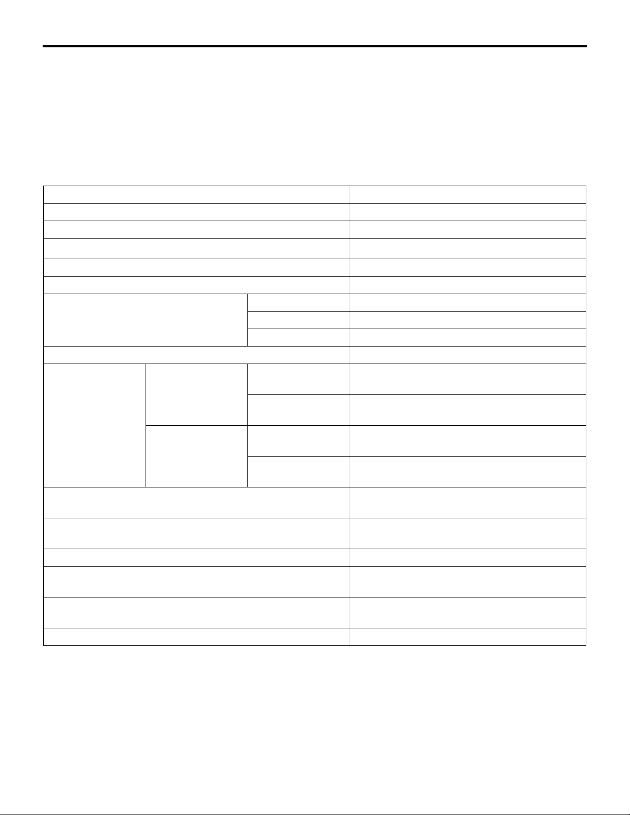
This model is equipped with a newly developed 4B11
engine. It is a 4-cylinder, double overhead camshaft
(DOHC) engine with a 2.0-L cylinder displacement.
This engine has adopted the following features:
MAIN SPECIFICATIONS
Descriptions Specifications
Engine type 4B11
Bore × stroke mm (in) 86 (3.4) × 86 (3.4)
Total displacement cm3 (cu in)
Combustion chamber Pent-roof type
Number of cylinders 4
Valve mechanism Type DOHC
Intake valve 8
Exhaust valve 8
Compression ratio 10.0
Valve ti min g Intake valve Opens (BTDC) 3° − 28° <California>
Closes (ABDC) 45° − 20° <California>
Exhaust valve Opens (BBDC) 41° − 21° <California>
Closes (ATDC) 3° − 23° <California>
Maximum output kW/r/min (HP/r/min) 107/6,000 (143/6,000) <California>
Maximum torque N⋅ m/r/min (lbs-ft/r/min) 194/4,250 (143/4,250) <California>
Fuel injection system type Electronic control MPI
Ignition system type Electronic spark-advance control type (4-coil
Generator type Alternating current system (with built-in IC
Starter motor type Reduction drive type
• MIVEC (MITSUBISHI INNOVATIVE VALVE TIMING ELECTRONIC CONTROL SYSTEM) for
both the intake and exhaust valves
• Cylinder block made of an aluminum alloy
• Valve train with direct-acting valve tappets
• Silent timing chain
1,998 (121.9)
0° − 25° <except California>
48° − 23° <except California>
44° − 24° <except California>
0° − 20° <except California>
113/6,000 (152/6,000) <except California>
198/4,250 (146/4,250) <except California>
type)
regulator)
Page 3
ENGINE MECHANICAL
BASE ENGINE
11A-3
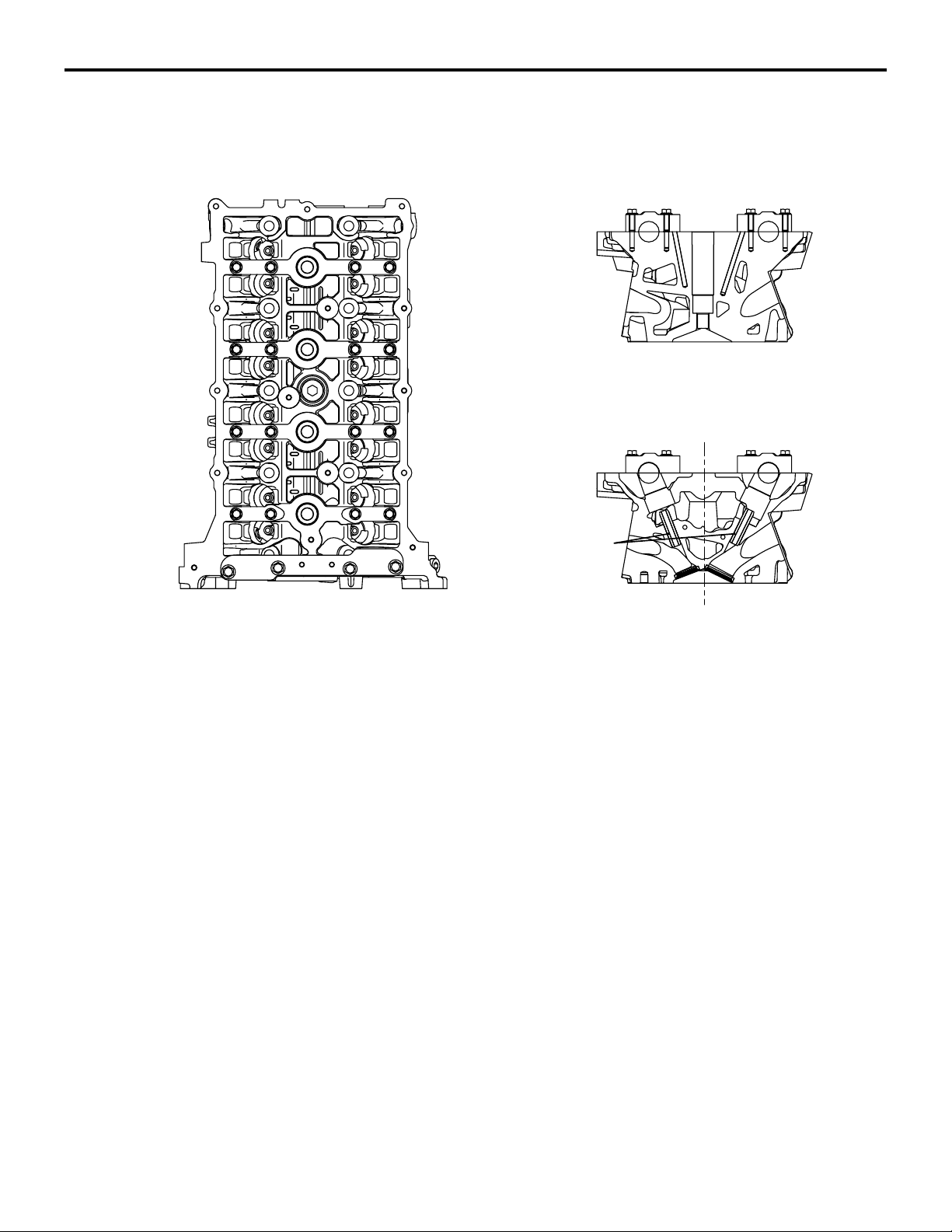
CYLINDER HEAD
Exhaust side
BASE ENGINE
M2112001001050
Intake side
Valve guide
A cylinder head made of an aluminum alloy, which is
lightweight and offers a high level of cooling effi
ciency, has been adopted. A pentroof combustion
chamber with a center spark plug has been adopted.
It has a small valve compound angle to realize a
compact chamber.
AK502483
Cross-flow type intake and exhaust ports have been
adopted. Two intake ports and two exhaust ports are
provided independently on the right and left sides.
Five camshaft bearings are provided at the intake
and exhaust sides, respectively. The No. 4 bearing
sustains the thrust load of the camshaft. Only the No.
AD
1 bearing uses a bearing cap that integrates both the
intake and exhaust sides.
VALVE SEATS
Sintered alloy valve seats have been adopted. The oversized (0.3 mm) service parts are available.
VALVE GUID ES
Valve guides that are common to both the intake and
exhaust have been adopted.
The oversized (0.25 mm) service parts are available.
Page 4
11A-4
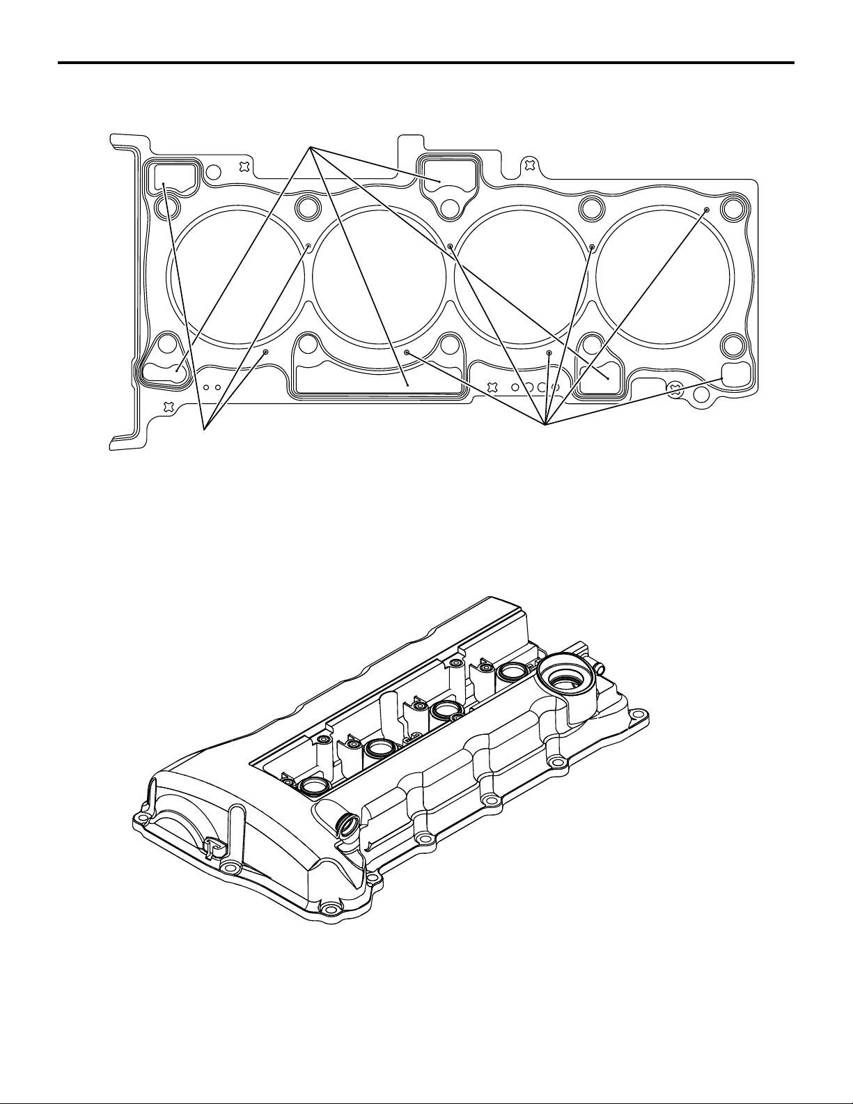
CYLINDER HEAD GASKET
ENGINE MECHANICAL
BASE ENGINE
Oil hole
Water hole
A dual-layer, metal type cylinder head gasket that
excels in heat resistance and sealing performance
has been adopted.
CYLINDER HEAD COVER
Water hole
AK604543
AB
A Plastic cylinder head cover has been adopted.
AK502485
Page 5
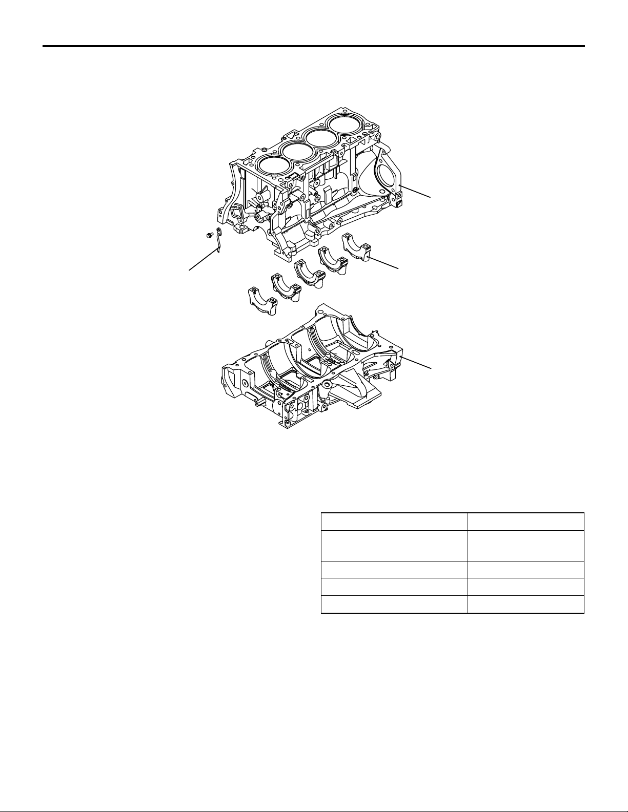
CYLINDER BLOCK
ENGINE MECHANICAL
BASE ENGINE
11A-5
Cylinder block
Oil jet
A cylinder block made of an aluminum alloy has
been adopted for weight reduction.
5 bearings are used for the crankshaft journals and
the No. 3 bearing sustains the thrust load of the
crankshaft.
The water jacket is the full Siamese type.
An oil jet is used in front of the cylinder block to supply engine oil to the timing chain.
Bearing cap
Ladderframe
AK502486
AE
ITEM SPECIFICATIONS
Distance between top and
230.1 (9.06)
crankshaft center mm (in)
Bore mm (in) 86 (3.4)
Bore pitch mm (in) 96 (3.8)
Stroke mm (in) 86 (3.4)
Page 6
11A-6
PISTONS
Front mark
ENGINE MECHANICAL
BASE ENGINE
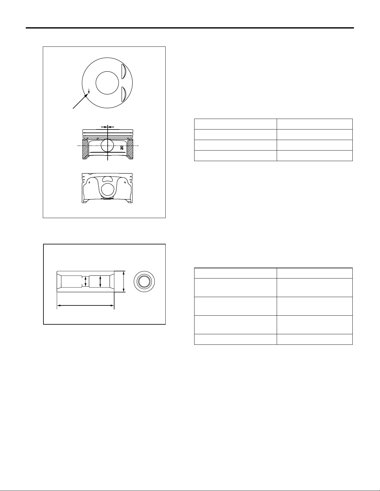
The pistons are made of a special aluminum alloy.
Their weight has been reduced by lowering their
overall height and increasing the depression at each
20
A
end of the piston pin.
The piston pin hole center is offset 0.8 mm (0.031 in)
towards the thrust side of the piston center.
The skirt portion along the perimeter of the piston is
finished with streaks that excel in oil retention and
seizure resistance.
PISTON PINS
d2
Piston offset
ITEM SPECIFICATIONS
Basic diameter mm (in) 86 (3.4)
Pin hole diameter mm (in) 21 (0.8)
Overall height mm (in) 50.5 (1.99)
AK603610
AB
The piston pins are the semi-floating type. Each pin
is press-fit and secured in the small end of the con
-
necting rod, while it floats in the piston.
ITEM SPECIFICATIONS
d1
D
Outer diameter (D) mm
21 (0.8)
(in)
h
Inner diameter (d1) mm
12 (0.5)
(in)
AK502996
AE
Inner diameter (d2) mm
10.5 (0.41)
(in)
Overall length (h) mm (in) 58 (2.3)
Page 7
PISTON RINGS
ENGINE MECHANICAL
BASE ENGINE
11A-7
Piston ring No. 1
Piston ring No. 2
Spacer
Oil ring
Rail
Piston ring No. 1
Maker mark
Oil ring
Piston ring No. 2
AK604544
AB
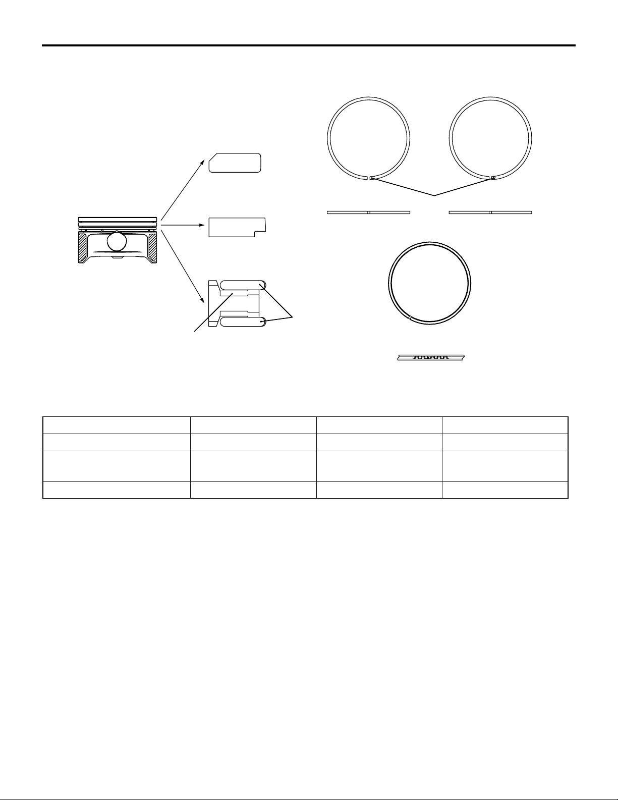
The piston rings consist of No. 1 and No. 2 rings and
an oil ring.
Item Piston ring No. 1 Piston ring No. 2 Oil ring
Shape Inside bevel, Barrel Taper undercut 3-piece, Barrel
Surface treatment (cylinder
Chrome plating Parkerizing Hard plated Parkerizing
contact surface)
Supplier mark 1T 2T None
Page 8
11A-8
CONNECTING RODS
d
ENGINE MECHANICAL
BASE ENGINE
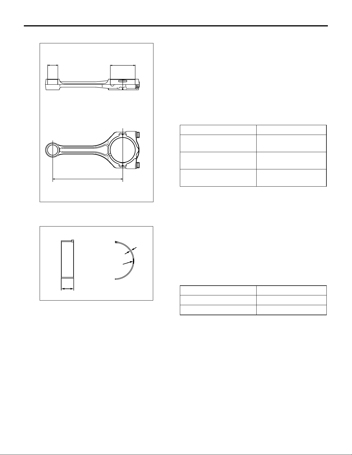
The connecting rods are made of highly rigid, forged
carbon steel. The cross section of the rod portion is
D
shaped like the letter H.
A fracture-split process has been adopted for splitting the big end of the connecting rod.
The fracture split connecting rod has the high insertion force between the rod and the cap as well as the
high installation location accuracy.
The oil holes that feed oil from the main journals of
the crankshaft to the crankshaft pins lubricate the
bearings at the big ends of the connecting rods.
Item Specifications
24
L
AK502491
CONNECTING ROD BEARINGS
Identification
color
H
AK502492
Small end hole diameter
21 (0.87)
(d) mm (in)
Big end hole diameter (D)
20
mm (in)
Center-to-center distance
51 (2.01)
149.25 (5.876)
(L) mm (in)
AD
The upper and lower connecting rod bearings are the
same. Each connecting rod bearing is provided with
A
a backing plate. Its bearing portion is made of an alu
minum alloy and its backing plate is made of ordinary
-
sheet steel.
The width of the connecting rod bearing has been
made as narrow as possible in proportion to the
bearing cap in order to reduce friction loss.
Item Specifications
AD
Width (H) mm (in) 17 (0.7)
Thickness (A) mm (in) 1.5 (0.06)
Page 9
CRANKSHAFT
ENGINE MECHANICAL
BASE ENGINE
11A-9
Balance weight
Balance weight
Oil hole
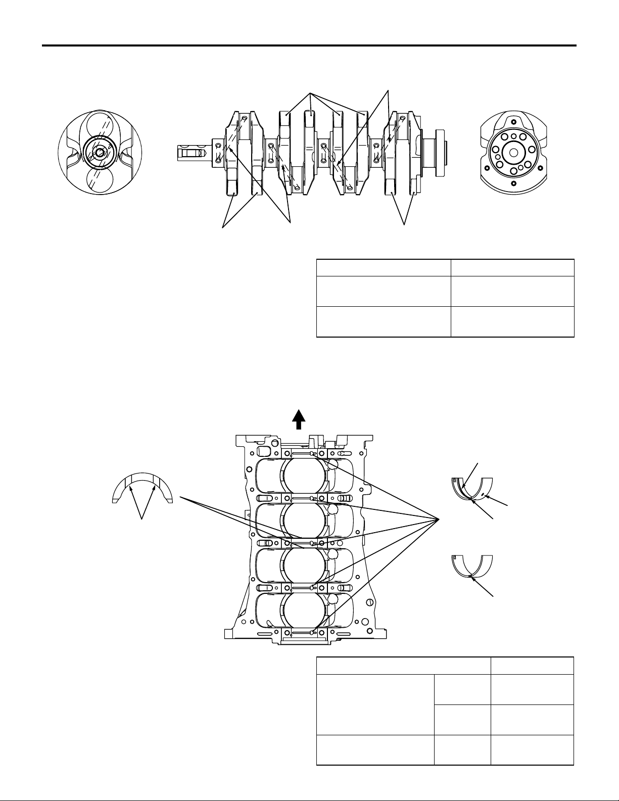
A forged crankshaft has been adopted.
It has 5 main bearings and 8 balance weights.
The crankshaft pins are located at equal 180° intervals.
The oil holes feed engine oil from the journals to the
pins.
A crankshaft sprocket and an oil pump drive shaft are
press-fit to the front of the crankshaft.
Oil hole
Balance weight
Item Specifications
Pin outer diameter mm
48 (1.9)
(in)
Journal outer diameter
52 (2.0)
mm (in)
AK502493AD
CRANKSHAFT BEARINGS, THRUST BEARINGS
Front
Thrust bearing
Groove
The upper crankshaft bearings have oil grooves and
the lower crankshaft bearings do not.
Each crankshaft bearing is provided with a backing
plate. Its bearing portion is made of an aluminum
alloy and its backing plate is made of ordinary sheet
steel. A thrust bearing, which sustains the load in the
thrust direction, is provided at each end of the No. 3
bearing.
Item Specifications
Crankshaft bearing Width mm
Crankshaft thrust
bearing
Lower bearing
Oil groove
Identification
color
Upper bearing
Identification
color
(in)
Thickness
mm (in)
Thickness
mm (in)
Oil hole
AK602940AC
18 (0.71)
2.0 (0.08)
2.0 (0.08)
Page 10
11A-10
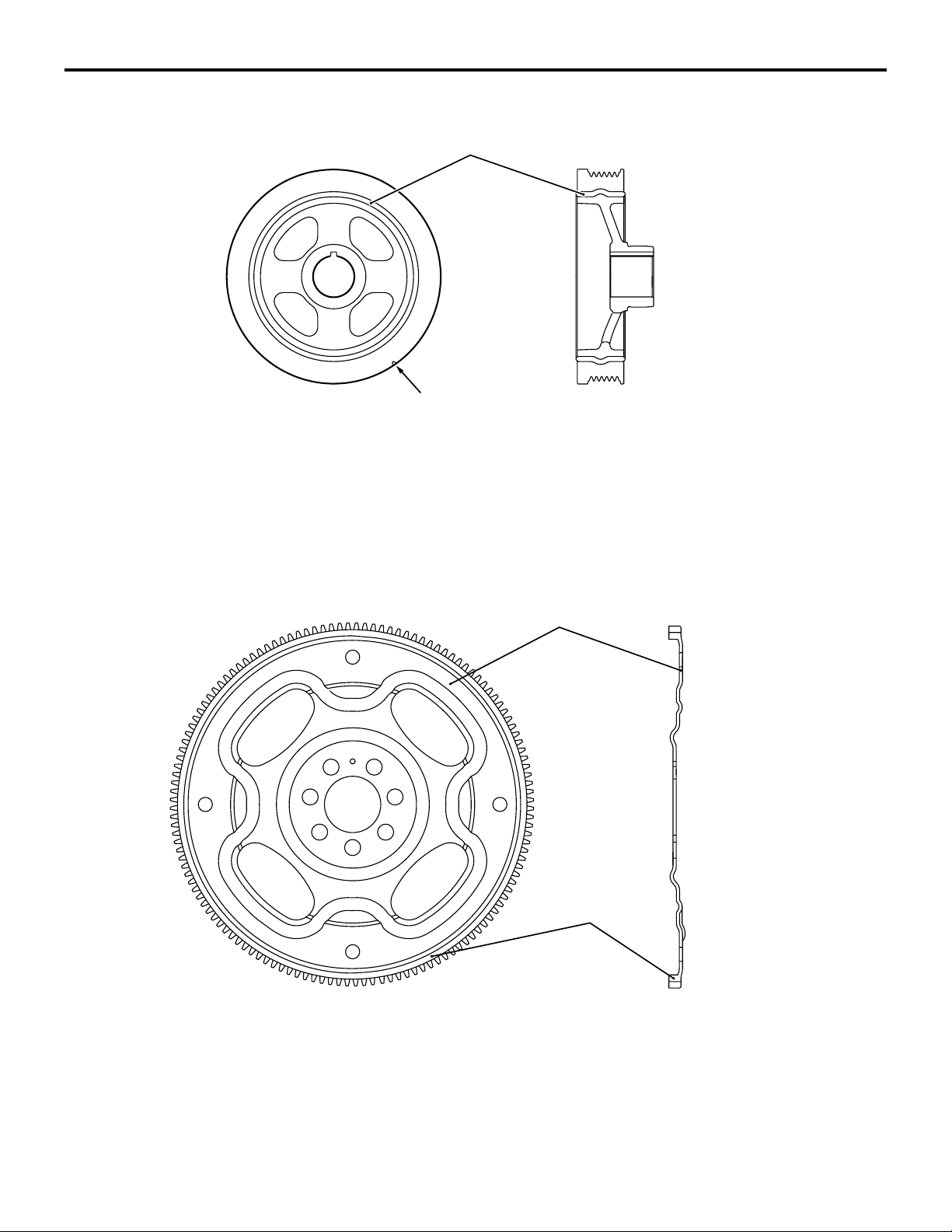
CRANKSHAFT PULLEY
ENGINE MECHANICAL
BASE ENGINE
Rubber
Timing mark
The pulley is made of cast iron.
The pulley portion has grooves for the V-ribbed belt
(with 6 crests).
The flange portion of the pulley has a timing mark
notch for checking the ignition timing.
DRIVE PLATE
AK604551
A torsion damper has been adopted to reduce the
torsional vibration of the crankshaft, as well as to
dramatically reduce noise and vibration in the
high-speed range.
Drive plate
AB
Ring gear
The drive plate is made of sheet metal. The drive plate is mounted with 7 bolts.
AK502496
AD
Page 11
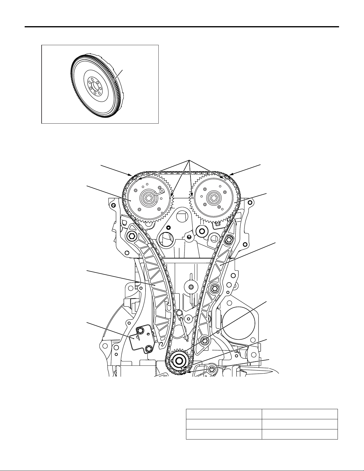
FLYWHEEL
Ring gear
ENGINE MECHANICAL
BASE ENGINE
A cast iron ring gear is a shrink fit in the iron casting
of the flywheel.
The flywheel is mounted with 7 bolts.
11A-11
TIMING CHAIN TRAIN
Timing mark
link plate (orange)
Exhaust V.V.T. sprocket
Tensioner lever
AK603618
AB
Timing mark
Timing mark
link plate (orange)
Intake V.V.T. sprocket
Chain guide
Timing chain
tensioner
The two camshafts are driven by the timing chain via
the camshaft sprockets.
The timing chain is a silent, endless type, consisting
of 180 links. It is installed around the V.V.T. sprockets
and the crankshaft sprocket.
Crankshaft spocket
Cranshaft spocket
timing mark
Timing mark
link plate (orange)
AK502497
AD
Three (orange) mark link plates are installed on the
timing chain to locate the sprockets.
Item Number of teeth
V.V.T. sprockets 54
Crankshaft sprocket 27
Page 12
11A-12
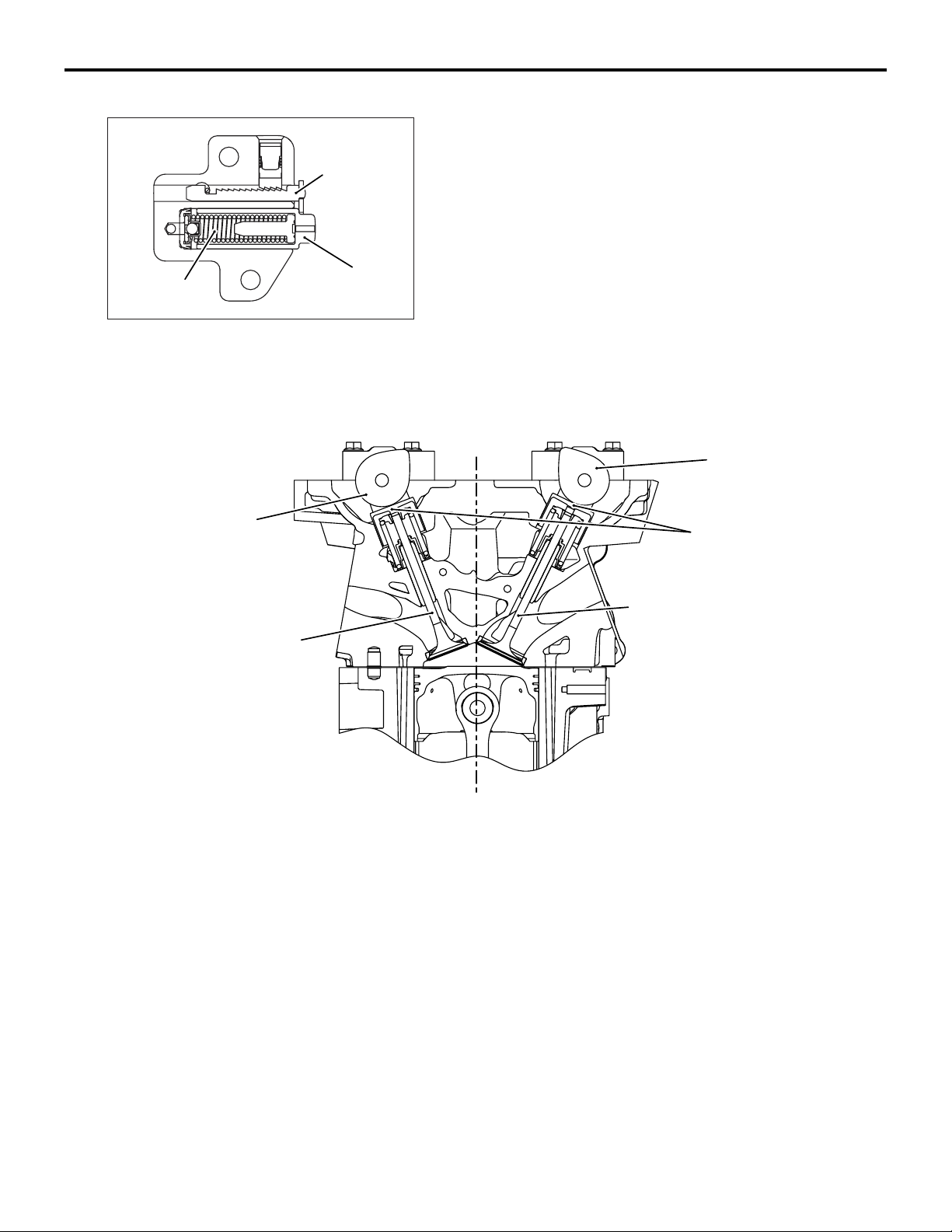
TIMING CHAIN TENSIONER
Rack and
washer
assembly
ENGINE MECHANICAL
BASE ENGINE
The tensioner maintains the tension of the timing
chain. It contains a piston with a built-in spring.
With the tensioner installed, its piston directly pushes
on the tension lever in order to automatically adjust
the tension of the timing chain.
Spring
VALVE TRAI N
Exhaust
camshaft
Exhaust valve
Piston
AK502997
AE
Intake
camshaft
Valve tappet
Intake valve
The valve train is the 4-valve, double overhead camshaft (DOHC) type in which the camshafts are
located above the valves.
Two intake and exhaust valves for each cylinder are
arranged in a V shape.
AK502499
AD
A valve tappet is interposed between the camshaft
and each valve, which allows the valve to open and
close.
Page 13
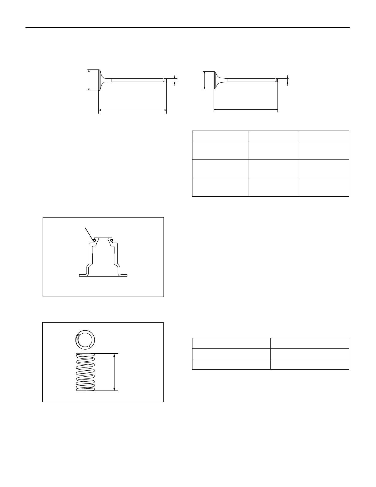
VALVES
ENGINE MECHANICAL
BASE ENGINE
Intake Exhaust
Dd dD
LL
11A-13
The valves are made of heat-resistant steel and are
nitrided on their entire surface.
VALVE STEM SEALS
Spring
AK502501
AD
AK502500
AD
Item Intake valve Exhaust valve
Head diameter
35 (1.4) 29 (1.1)
(D) mm (in)
Stem diameter
5.5 (0.22) 5.5 (0.22)
(d) mm (in)
Overall length (L)
mm (in)
113.180
(4.4559)
105.887
(4.1688)
The valve stem seals are integrated with the valve
spring seats.
The valve stem seal portion excels in sealing performance and is equipped with a spring to prevent oil
from descending.
VALVE SPRI NGS
To prevent the engine from surging at high speeds,
unequal-pitch springs are used.
Item Specifications
Free height (h) mm (in) 47.44 (1.867)
Total number of windings 8.67
AK502502hAD
Page 14
11A-14
VALVE TAPPETS
Thickness
Identification
mark
ENGINE MECHANICAL
BASE ENGINE
To adjust the valve lift, 47 sizes of valve tappets are
available in 0.015 mm (0.0006 in) increments, from
3.000 mm (0.1181 inch) to 3.690 mm (0.1453 in).
AK502503
AD
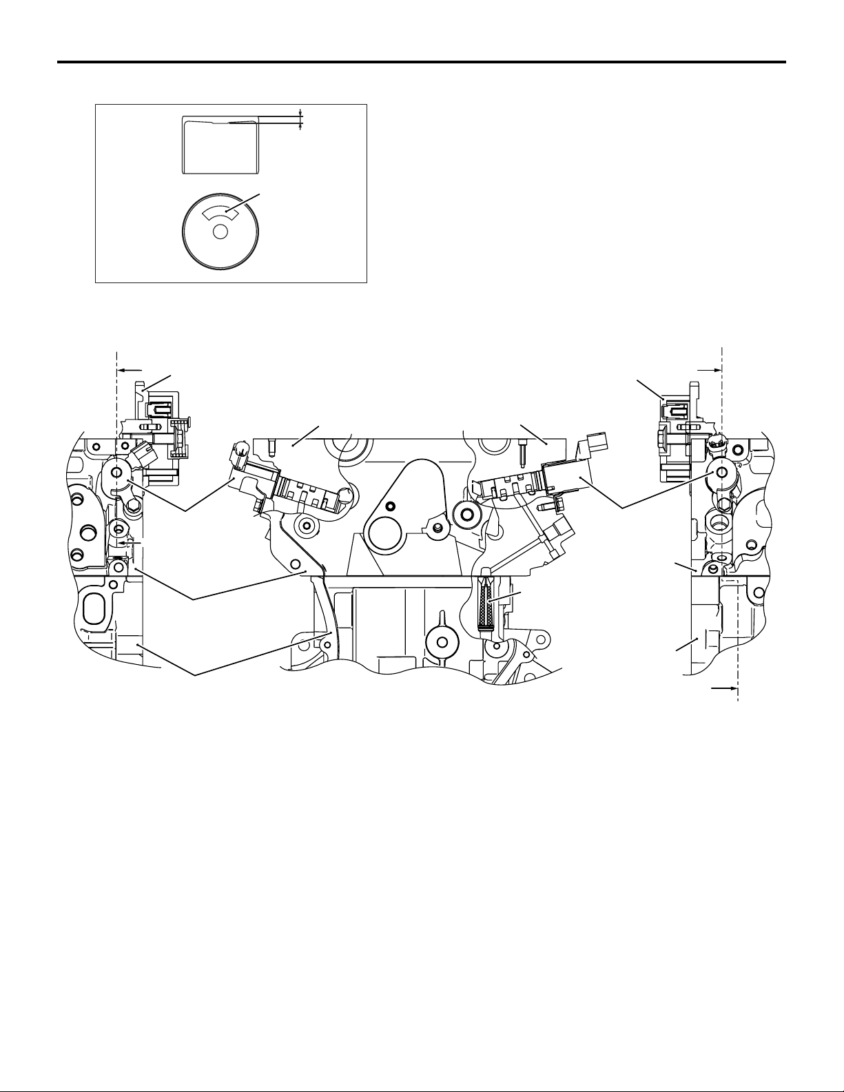
MIVEC (MITSUBISHI INNOVATIVE VALVE TIMING ELECTRONIC CONTROL SYSTEM)
A
Exhaust V.V.T. sprocket
Engine oil
control valve
A
Cylinder head
Section A-A
Intake V.V.T. sprocket
Section B-B
Engine oil
control valve
Cylinder head
Engine oil control
valve filter
Cylinder block
B
Cylinder block
The MIVEC consists of the parts shown in the illustration.
B
AK503014
AE
This system continuously varies and optimally controls the opening and closing timing of the individual
intake and exhaust valves, in order to improve torque
and power output in all speed ranges.
Page 15
ENGINE MECHANICAL
BASE ENGINE
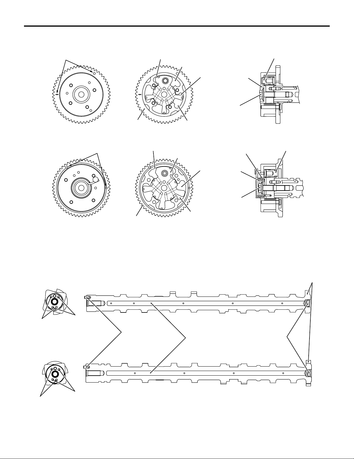
V.V.T. SPROCKET (VARIABLE VALVE TIMING SPROCKET)
Intake V.V.T. sprocket
Timing mark
Sprocket
Vane housing
Vane roter
Advance oil
chamber
V.V.T. sprocket
bolt
Retard oil chamber
11A-15
Stopper pin
Vane
bushing
Exhaust V.V.T. sprocket
Timing mark
Sprocket
Vane housing
Vane roter
The engine oil control valve controls the hydraulic
pressure in order to move the vane rotor in the V.V.T.
sprocket to optimally control valve timing.
CAMSHAFT
Intake camshaft
Advance oil
chamber
V.V.T. sprocket
bolt
Retard oil chamber
Vane bushing
Spring
Stopper pin
AK503061
Cam positon
sensing cam
AD
Retard
oil channel
Exhaust camshaft
Retard
oil channel
Advance
oil channel
Dowel pin
Advance
oil channel
The camshaft are hollow for weight reduction.
Each camshaft is provided with an oil passage to
guide the hydraulic pressure from the engine oil con
trol valve to the V.V.T. sprocket.
Hollow section
Sealing cap
AK502506
A cam position sensing cam for detecting the cam
position (used by the cam position sensor) is inte
-
grated at the back of each camshaft.
AD
-
Page 16
11A-16
ENGINE MECHANICAL
BASE ENGINE
Item Specifications
Overall length mm (in) Intake 435.00 (17.126)
Exhaust 438.27 (17.255)
Journal outer diameter mm (in) Intake No.1 30 (1.2)
No.2 − 5 24 (0.9)
Exhaust No.1 36 (1.4)
No.2 − 5 24 (0.9)
Camshaft lift mm (in) Intake 8.45 (0.333)
Exhaust 8.20 (0.323)
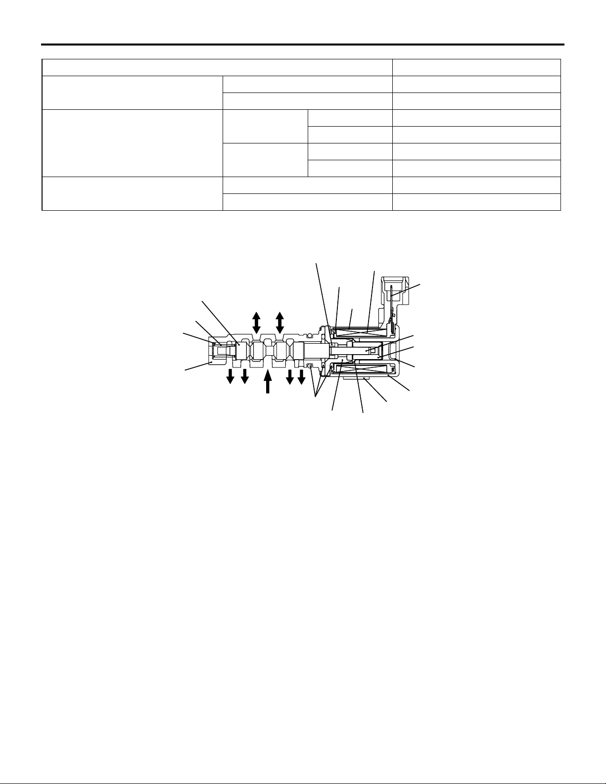
ENGINE OIL CONTROL VALVE
Default
pressure
chamber
Pump
Plunger spring
Spring guide
Valve sleeve
Spool
Pressure
chamber
Drain
The engine oil control valve consists of a solenoid
valve, which switches the hydraulic pressure that
acts on the vane rotor in the V.V.T. sprocket assem
bly. This valve is actuated by a signal from the
engine ECU.
Drain
-
Insulation
coilar
O-ring
Stator
Bobbin
Tape
Enameled
copper wire
Terminal
Shaft
Plunger
Seal cap
Yo k e
Bracket
Guide cap
AK302997AE
Page 17
TIMING CHAIN CASE
ENGINE MECHANICAL
Timing chain case
Oil seal
BASE ENGINE
11A-17
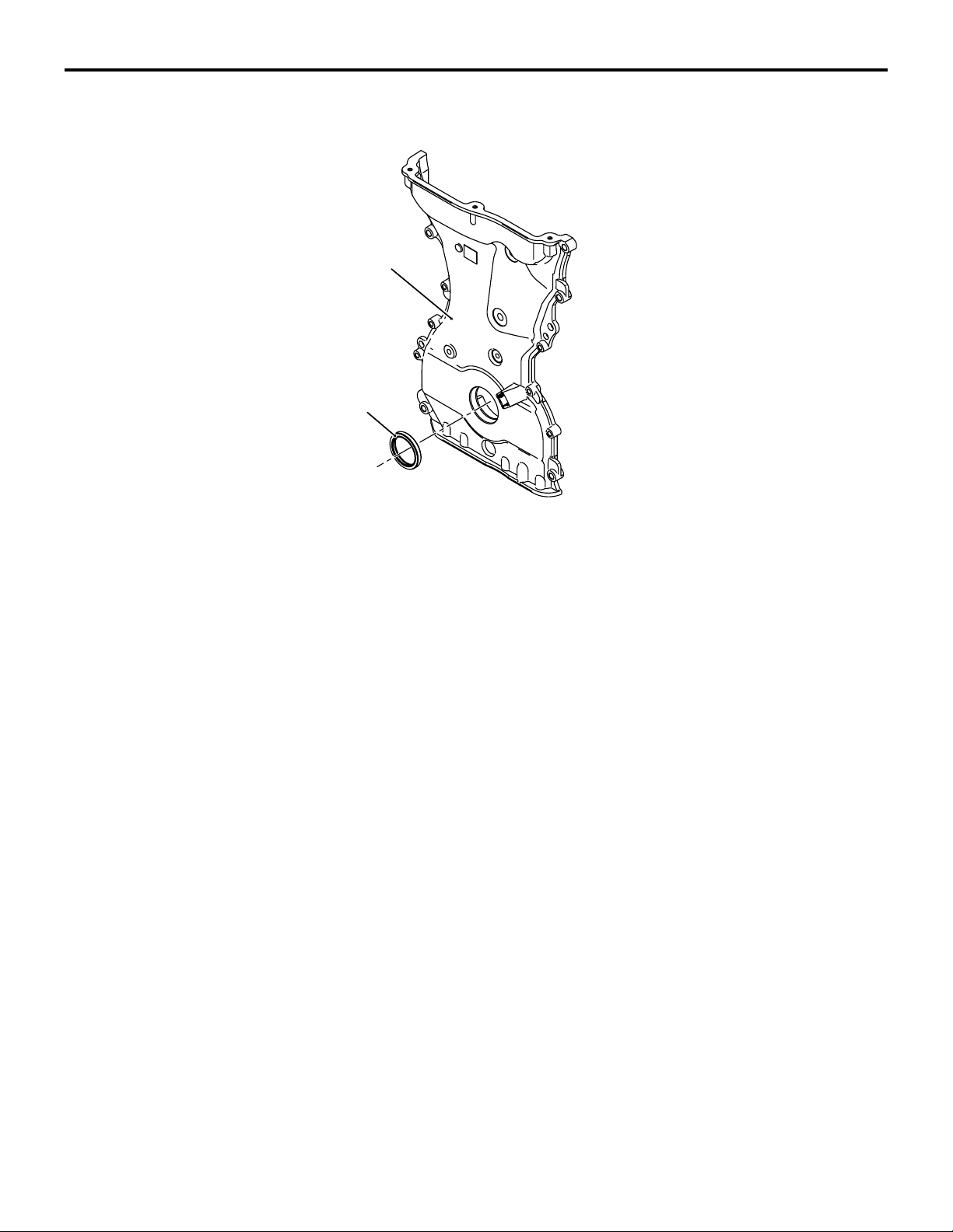
The timing chain case is made of an aluminum alloy.
A front crankshaft oil seal is press-fit into the case.
AK502507
AD
Page 18

NOTES
Page 19

GROUP 17
ENGINE AND
EMISSION
CONTROL
CONTENTS
17-1
ENGINE CONTROL . . . . . . . . . . . . . . 17-2
GENERAL INFORMATION. . . . . . . . . . . . . 17-2
AUTO-CRUISE CONTROL SYSTEM 17-2
GENERAL INFORMATION. . . . . . . . . . . . . 17-2
CONSTRUCTION AND OPERATION . . . . 17-5
EMISSION CONTROL . . . . . . . . . . . . 17-8
GENERAL DESCRIPTION . . . . . . . . . . . . . 17-8
CRANKCASE VENTILATION SYSTEM . . . 17-10
EVAPORATIVE EMISSION CONTROL
SYSTEM . . . . . . . . . . . . . . . . . . . . . . . . . . . 17-11
EXHAUST GAS RECIRCULATION (EGR)
SYSTEM <California> . . . . . . . . . . . . . . . . . 17-12
EMISSION REDUCTION SYSTEMS. . . . . . 17-14
Page 20
17-2
ENGINE AND EMISSION CONTROL
ENGINE CONTROL
ENGINE CONTROL
GENERAL INFORMATION
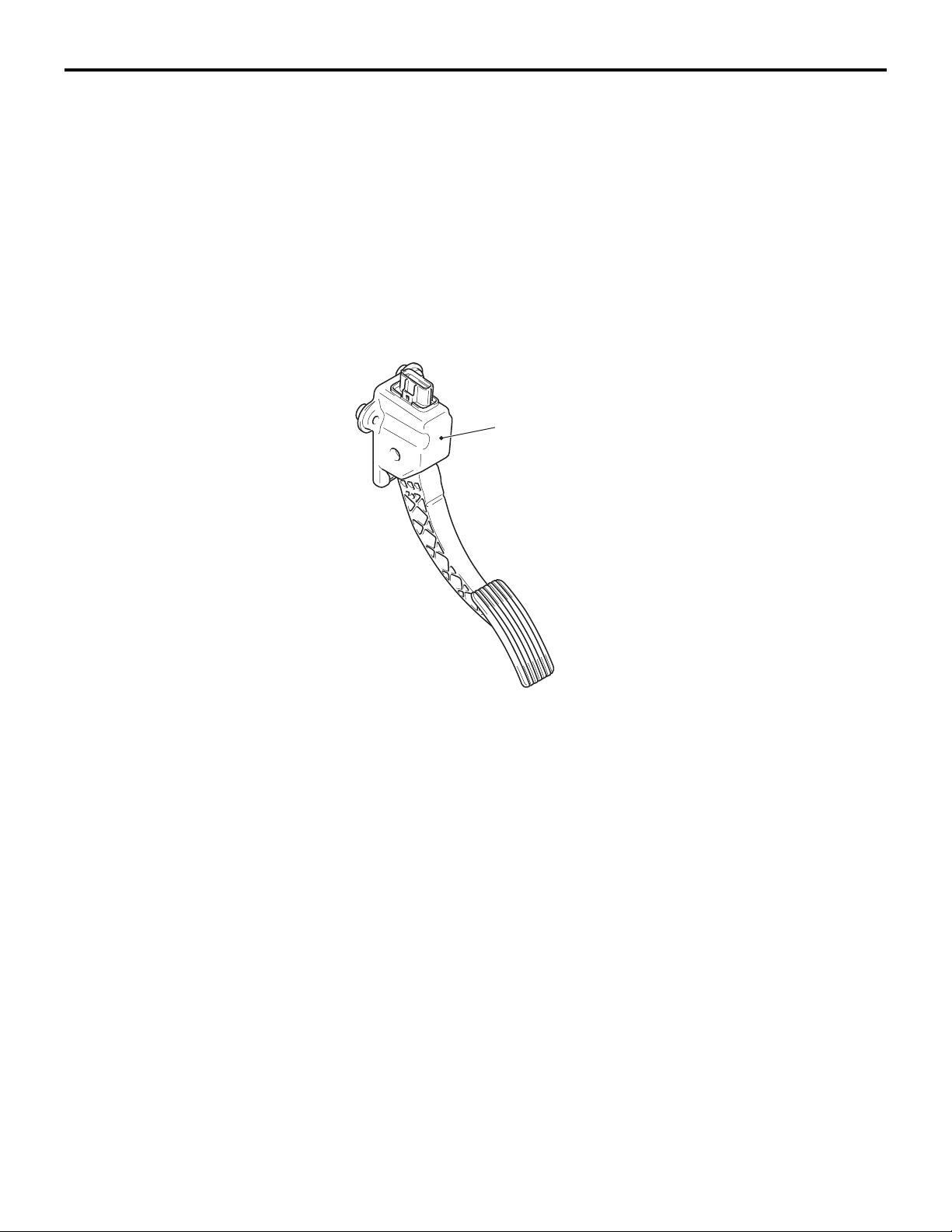
For the accelerator system, an electronic throttle
valve control system has been adopted, disposing of
an accelerator cable. This system detects the accel
erator pedal travel by using a accelerator pedal position sensor (APP sensor) in the accelerator pedal
assembly for electronic control of the throttle valve
angle.
CONSTRUCTION DIAGRAM
M2170001000659
-
Accelerator pedal assembly
[Built-in accelerator pedal position
sensor (APP sensor)]
AUTO-CRUISE CONTROL SYSTEM
GENERAL INFORMATION
By using the auto-cruise control system, the driver
can drive at preferred speeds in a range of approxi
mately 40 to 200 km/h (25 to 125 mph) without
depressing the accelerator pedal.
AC505671
For this auto-cruise control system, in conjunction
with the electronic throttle valve control system, the
engine control module (ECM) electronically controls
the throttle valve.
CONSTRUCTION DIAGRAM
AB
M2170001000682
Page 21
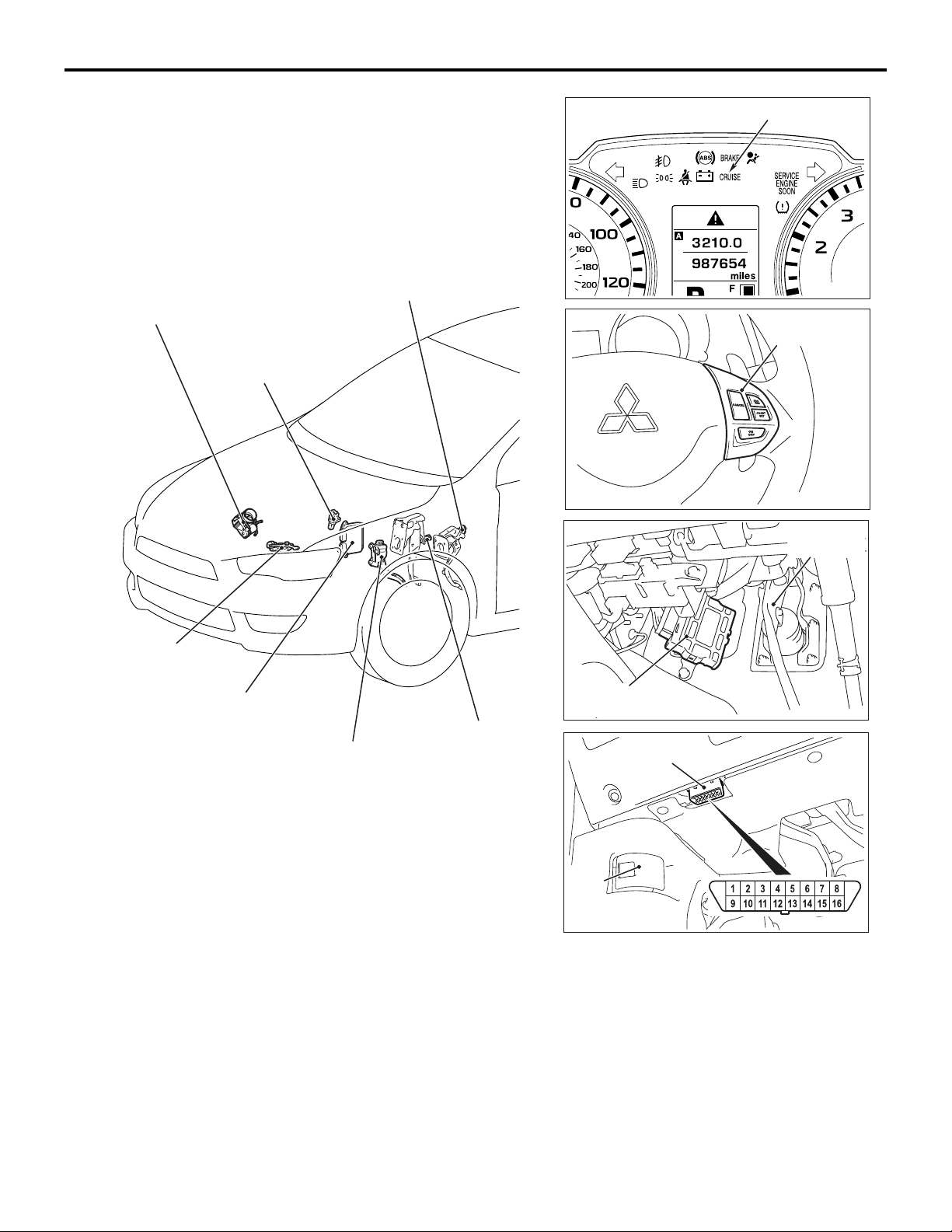
Throttle body
[Built-in throttle position sensor
(TP sensor) and
throttle actuator control motor
(TAC motor)]
Vehicle speed
sensor <M/T>
ENGINE AND EMISSION CONTROL
AUTO-CRUISE CONTROL SYSTEM
Clutch switch <M/T>
17-3
"CRUISE" indicator light
AC611099
Auto-cruise
control switch
Transmission
range switch
<CVT>
Engine control
module (ECM)
Accelerator pedal
[Built-in accelerator
pedal position sensor
(APP sensor)]
AC611098
Stoplight switch
Transaxle control
module (TCM) <CVT>
Data link connector
Hood
lock
release
handle
AC611100
Brake pedal
assembly
AC606956
AC611101
AC611102
AD
Page 22

17-4
ENGINE AND EMISSION CONTROL
AUTO-CRUISE CONTROL SYSTEM
COMPONENTS AND FUNCTIONS
Component Function
Accelerator pedal position sensor (APP sensor) Informs the ECM of the accelerator pedal
depression.
Auto-cruise control switch "ON/OFF" switch Power switch for auto-cruise control system.
"ACC/RES" switch Vehicle speed is set with the "ACC/RES" switch and
"COAST/SET" switch
"CANCEL" switch Cancels the cruise speed setting.
Cancel system Clutch switch <M/T> Because the constant speed driving is cancelled by
Stoplight switch • Because the constant speed driving is canceled
Transmission range
switch <CVT>
"COAST/SET" switch.
the clutch operation, the clutch pedal status is
detected.
by the brake operation, it detects the brake pedal
status.
• As for the stoplight switch, two built-in switches,
the stoplight switch which is also used for the
stoplight illumination and the brake switch which
is used exclusively for the auto-cruise control, are
integrated, and thus the reliability is enhanced.
Because the constant speed driving is cancelled by
the selector lever operation, it detects the "N"
position.
"CRUISE" indicator light The light is included in the combination meter and
illuminates when the "ON/OFF" switch is pressed
(auto-cruise control system: ON).
Data link connector If the M.U.T.-III scan tool is connected, the input
check code from the ECM can be read.
Engine control module (ECM) • Based on the input signal from each sensor and
switch, it outputs the throttle opening instruction
signal to the TAC motor.
• Based on the input signal from each sensor and
switch, it outputs the transaxle control signal to
the TCM <CVT>.
• Based on the vehicle speed signal from the
vehicle speed sensor, it calculates the vehicle
speed <M/T>.
• Based on the secondary pulley speed sensor
signal from the TCM, it calculates the vehicle
speed <CVT>.
• Based on the selector lever "N" position signal of
the transmission range switch from the ECM, it
cancels constant speed driving. <CVT>.
• Outputs the ON/OFF signals of "CRUISE"
indicator light and auto-cruise control system.
• The diagnostic trouble code signal is sent to the
"CRUISE" indicator light.
• The input check code is sent to the data link
connector.
Throttle actuator control motor (TAC motor) The throttle valve opens and closes in response to
the throttle angle signal from the ECM.
Page 23
ENGINE AND EMISSION CONTROL
AUTO-CRUISE CONTROL SYSTEM
17-5
Component Function
Throttle position sensor (TP sensor) Informs the ECM of the throttle valve opening angle.
Transaxle control module (TCM) <CVT> • Based on the transaxle control signal from the
ECM, it controls the transaxle.
• Outputs the signal from the secondary pulley
speed sensor to the ECM.
• Transmits the selector lever "N" position signal
from the transmission range switch to the ECM.
Vehicle speed sensor <M/T> Transmits the vehicle speed signal proportional to
the vehicle speed to the ECM.
CONSTRUCTION AND OPERATION
SYSTEM OUTLINE
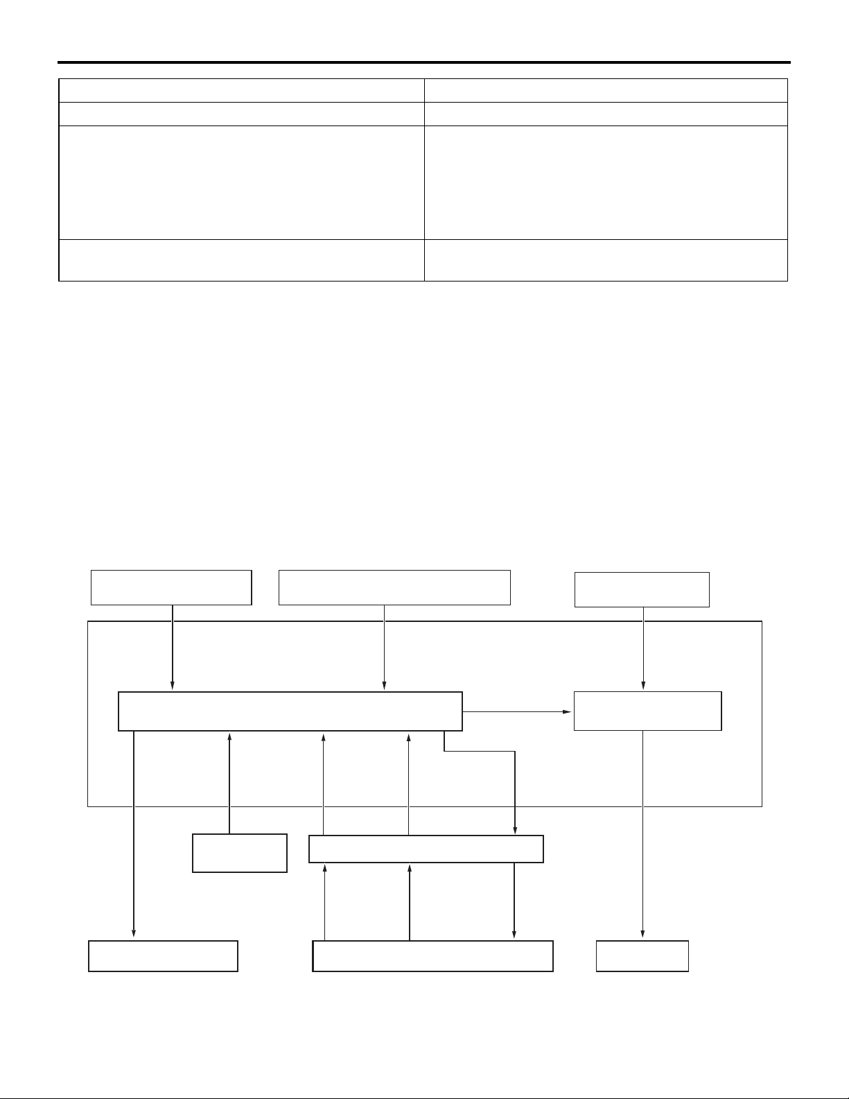
The ECM calculates the auto-cruise control system
operation status when the ECM receives input sig
nals from the auto-cruise control switch, vehicle
speed and cancel system [stoplight switch and clutch
switch <M/T> or transmission range switch <CVT>].
BLOCK DIAGRAM
Auto-cruise control switch
ON/OFF
signal
Cruise control section
Stoplight switch, clutch switch <M/T>
ON/OFF
signal
M2170002000232
The engine control section sends the target acceler
ator pedal opening angle value for auto-cruise control system, the TCM issues a command to transaxle
control <CVT>, and the gauge issues an ON/OFF
command for the "CRUISE" indicator light.
In the engine control section, the target throttle valve
opening angle value is calculated from the target
accelerator pedal opening angle value for
auto-cruise control system and the actual accelerator
angle value.The vehicle speed is then controlled by
applying the TAC motor.
APP sensor
ECM
Actual accelerator
pedal opening
Target accelerator
pedal opening
angle signal
Engine control section
angle signal
-
Vehicle speed
sensor <M/T>
"CRUISE"
indicator light
ON/OFF signal
"CRUISE" indicator light
Vehicle
speed
signal
<M/T>
Secondary
pulley speed
sensor signal
<CVT>
TCM <CVT>
Secondary
pulley speed
sensor signal
<CVT>
Transmission
range switch
signal <CVT>
Transmission
range switch
signal <CVT>
Transaxle
Shift control
signal <CVT>
Shift control
signal <CVT>
Target throttle
valve opening
angle signal
TAC motor
AC611103
Page 24

17-6
ENGINE AND EMISSION CONTROL
AUTO-CRUISE CONTROL SYSTEM
SYSTEM FUNCTIONS
.
SET FUNCTION
1. During driving with the vehicle speed range from
approximately 40 to 200 km/h (25 to 125 mph),
press and release the "COAST/SET" switch.
2. The vehicle speed when the "COAST/SET" switch
is released is memorized. Thereafter, the constant
speed driving is performed at that vehicle speed.
3. When the "COAST/SET" switch is operated
during the driving with the vehicle speed of
approximately 200 km/h (125 mph) or more, the
constant speed driving will not be performed.
.
COAST FUNCTION
1. When the "COAST/SET" switch is continuously
pressed for 0.5 seconds or longer during constant
speed driving, the throttle valve becomes fully
closed while the switch is pressed, and the
vehicle is decelerated.
2. When the "COAST/SET" switch is released, the
vehicle speed at that time is now memorized.
Thereafter, the constant speed driving is
performed at that vehicle speed.
3. Also when the "COAST/SET" switch is pressed
for less than 0.5 second, the vehicle is
decelerated 1.6 km/h (1 mph) from the vehicle
speed of constant speed driving, and the
decelerated vehicle speed is now memorized.
Thereafter, the constant speed driving is
performed at that vehicle speed.
4. When the "COAST/SET" switch is continuously
pressed and the vehicle speed is decelerated to
approximately 40 km/h (25 mph) or less, the set
function and coast function are cancelled, and the
constant speed driving is cancelled.
.
RESUME FUNCTION
1. When the "CANCEL" switch is pressed or the
brake pedal is depressed during the constant
speed driving, it cancels the constant speed
driving.
2. Subsequently, when the "ACC/RES" switch is
pressed during driving with the vehicle speed of
approximately 40 km/h (25 mph) or more, the
constant speed driving is performed with the
vehicle speed memorized at the last cancellation
of constant speed driving.
.
ACCEL FUNCTION
1. When the "ACC/RES" switch is continuously
pressed for 0.5 second or more during constant
driving, it accelerates the vehicle with specified
acceleration while the switch is pressed.
2. Then, when the "ACC/RES" switch is released,
the vehicle speed at that time is now memorized.
Thereafter, the constant speed driving is
performed at that vehicle speed.
3. Also, when the "ACC/RES" switch is pressed for
less than 0.5 second, the vehicle is accelerated
1.6 km/h (1 mph) from the vehicle speed of
constant speed driving, and the accelerated
vehicle speed is now memorized. Thereafter, the
constant speed driving is performed at that
vehicle speed.
4. It is possible to keep pressing the "ACC/RES"
switch until the vehicle speed is accelerated to
approximately 200 km/h (125 mph) or above.
However, after the "ACC/RES" switch is released,
the vehicle speed of approximately 200 km/h (125
mph) becomes the newly memorized vehicle
speed. Thereafter, the constant speed driving is
performed at that speed.
.
CANCEL FUNCTION
When any of the following conditions are satisfied,
the constant speed driving will be cancelled.
• The auto-cruise control system is stopped by the
pressing the "ON OFF" switch.
• The "CANCEL" switch is pressed.
• The brake pedal is depressed.
• The clutch pedal is depressed <M/T>.
• The selector lever is shifted to the "N" position
<CVT>.
• The vehicle speed becomes approximately 40
km/h (25 mph) or less.
• The vehicle speed is reduced 15 km/h (9 mph) or
more from the speed at which the constant speed
driving was started.
• An abnormality occurs in the vehicle speed signal.
• The engine coolant temperature becomes abnormally high.
• An abnormality occurs to the ECM.
• An abnormality occurs to the TCM <CVT>.
• An abnormality occurs to the CAN communica-
tion.
.
Page 25

ENGINE AND EMISSION CONTROL
AUTO-CRUISE CONTROL SYSTEM
17-7
FAIL-SAFE FUNCTION
When any of the following conditions are satisfied,
the auto-cruise control system function is stopped
until the system returns to normal. Also, when any of
the conditions are satisfied during the constant
speed driving, the constant speed driving is can
celled immediately.
• An abnormality occurs to the auto-cruise control
switch.
• An abnormality occurs to the stoplight switch.
When any of the following conditions are satisfied,
stop the vehicle once and turn the ignition switch to
"LOCK" (OFF). Otherwise, even when the system
returns to normal, the auto-cruise control system
function will continue to be stopped. Also, when any
of the conditions are satisfied during the constant
speed driving, the constant speed driving is can
celled immediately.
-
-
• ECM abnormality
• TP sensor abnormality
• APP sensor abnormality
.
DIAGNOSIS FUNCTION
• The diagnostic trouble code check is possible
with the "CRUISE" indicator light.
• To facilitate the system check, check the service
data output with the M.U.T.-III.
NOTE: For diagnostic items, service data output
items, and check method, refer to the Service Man
ual.
-
Page 26
17-8
ENGINE AND EMISSION CONTROL
EMISSION CONTROL
EMISSION CONTROL
GENERAL DESCRIPTION
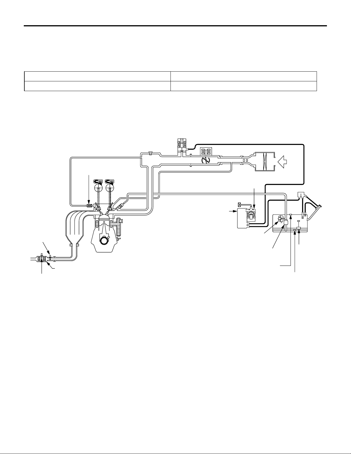
The following changes have been made to the controls of the 2.4L engine provided on the GALANT.
Improvement / Additions Remark
Addition of HC trap catalytic converter <California> HC decrease
SYSTEM CONFIGURATION DIAGRAM
<Except for California>
Evaporative emission
purge solenoid
Positive crankcase
ventilation valve
Evaporative
emission
canister
M2171000101024
Evaporative emission
ventilation valve
Heated oxygen
sensor (front)
Three-way catalytic converter
Heated oxygen
sensor (rear)
Fuel pressure
regulator
Fuel pump
Fuel tank differential
pressure sensor
Fuel tank
Fuel level
sensor
Fuel tank
temperature
sensor
AK604140
AB
Page 27
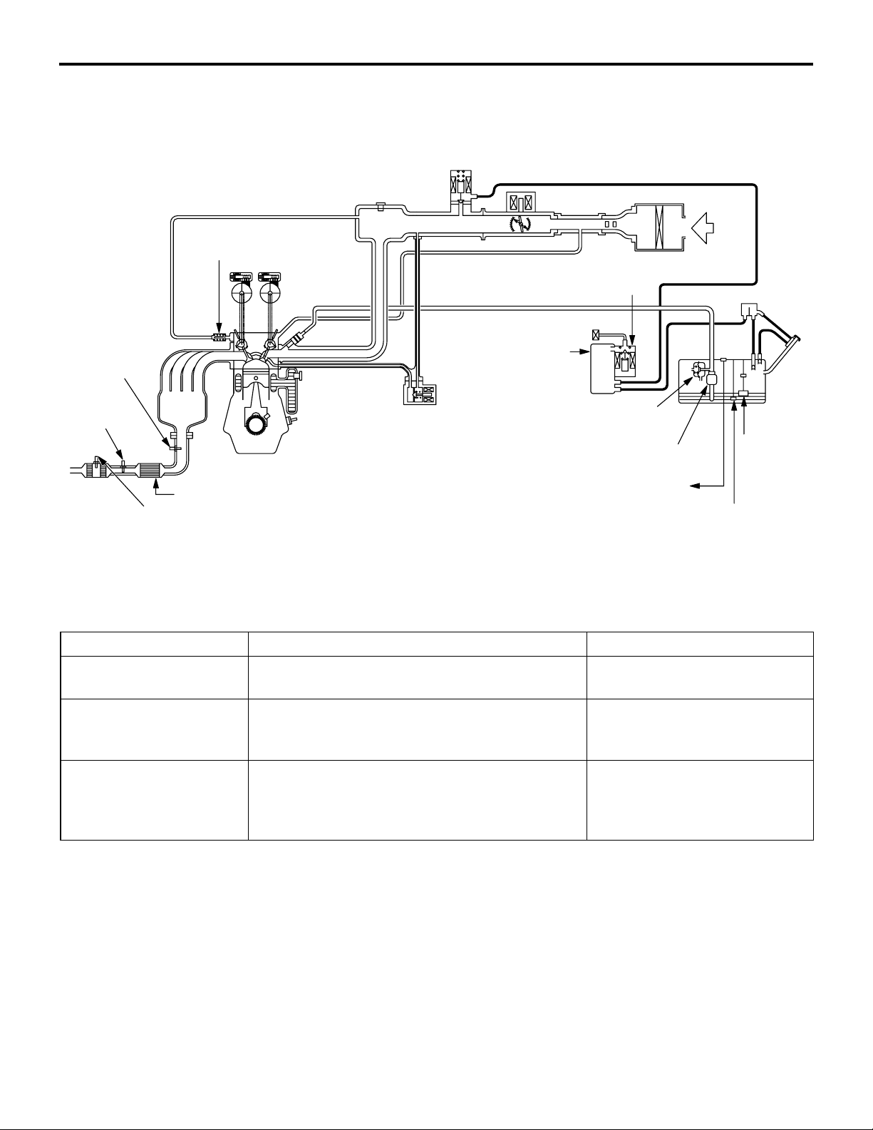
<California>
Heated
oxygen
sensor
(front)
Heated
oxygen
sensor
(rear)
Positive crankcase
ventilation valve
ENGINE AND EMISSION CONTROL
EMISSION CONTROL
Evaporative emission
purge solenoid
Evaporative emission
ventilation valve
Evaporative
emission
canister
EGR valve
(stepper motor)
Fuel pressure
regulator
Fuel pump
17-9
Fuel
tank
Fuel level
sensor
HC trap
catalytic
converter
Three-way catalytic converter
Heated oxygen sensor (3rd)
Fuel tank differential
pressure sensor
Fuel tank
temperature
sensor
Exhaust gas cleaning devices list
System Objective / Function Composition parts
Crankcase ventilation
system
Evaporative emission
control system
HC decrease
Re-combustion of blow-by gas.
HC decrease
Re-combustion of fuel vapor gas.
Positive crankcase ventilation
(PCV) valve
• Canister
• Evaporative emission purge
solenoid
Exhaust gas recirculation
(EGR) system
<California>
NOx decrease
Reduce NOx generation by controlling EGR
volume according to engine warm-up condition
EGR valve
and driving conditions.
AK604141
AB
Page 28
17-10
ENGINE AND EMISSION CONTROL
EMISSION CONTROL
System Objective / Function Composition parts
Emission
reduction
systems
Air-fuel ratio
feedback
control
Decrease of CO, HC and NOx
Controls air-fuel ratio of air-fuel mixture to
become theoretical air-fuel ratio (about 14.7),
which is when the 3-way catalytic converter's
cleaning performance is best. It also controls
optimum fuel supply based on coolant
• ECM
• Mass airflow sensor
• Injectors
• Heated oxygen sensor
• Crankshaft position sensor
etc.
temperature, driving conditions etc.
Catalytic
converter
Decrease of CO, HC and NOx
It facilitates oxidation of CO and HC and
reduction of NOx so that all 3 component gases
are cleaned simultaneously.
HC trap
catalytic
converter
<California>
HC decrease
During cold operation of engine, exhaust HC is
temporarily absorbed. And then Exhaust HC is
released when temperature reaches to level at
which catalyst is activated. This allows HC to be
reduced.
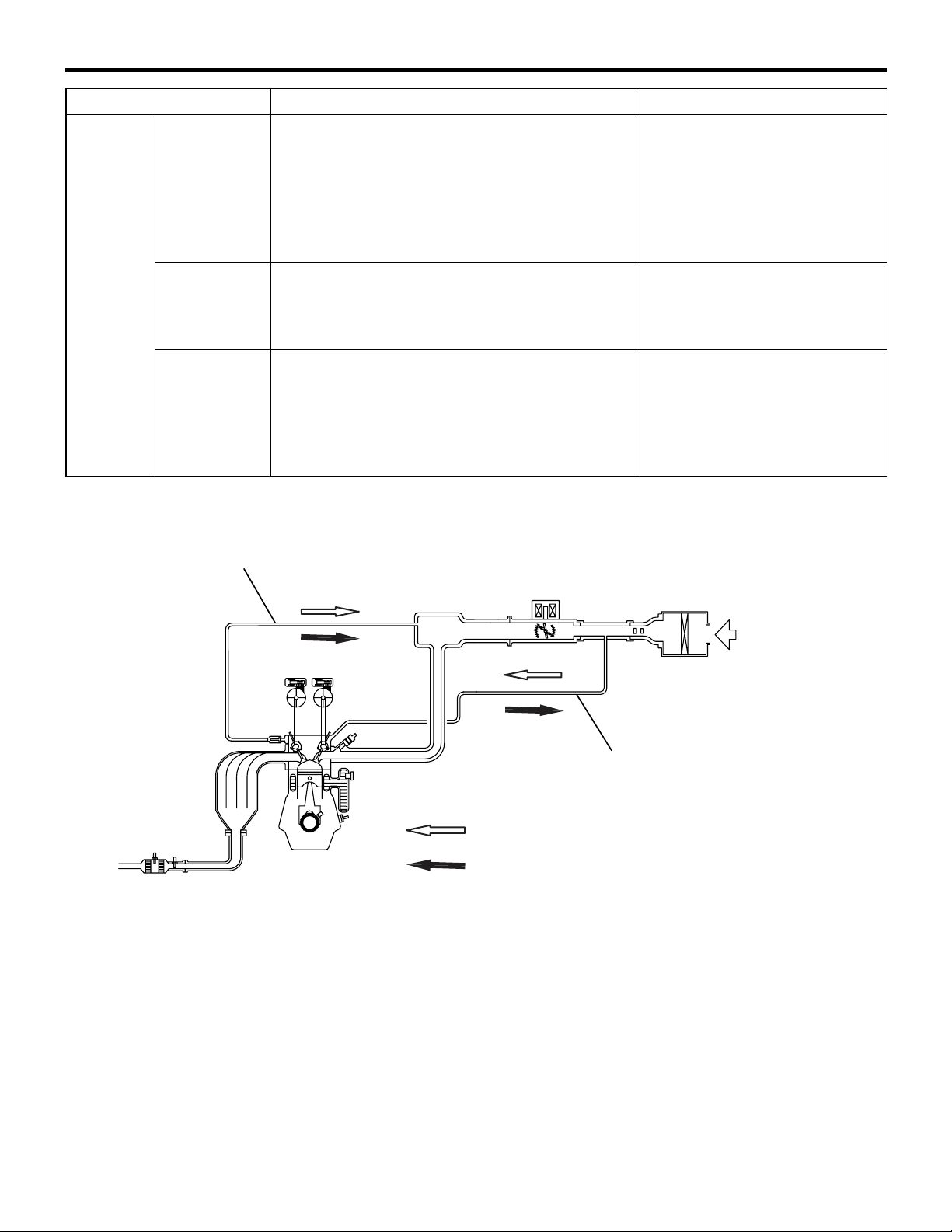
CRANKCASE VENTILATION SYSTEM
Ventilation hose
PCV valve
Monolith catalyst
Monolith catalyst
M2171000400129
Air cleaner
A blow-by gas reduction device prevents blow-by
gas from being expelled into the atmosphere and is
of closed type. A positive crankcase ventilation
(PCV) valve is provided in the ventilation hose from
the rocker cover to the intake manifold. During low
load driving, clean air is supplied to the crankcase by
the air intake hose via the breather hose and rocker
cover, and it mixes with the blow-by gas in the crank
Breather hose
Flow of blow-by gas and clean air (low load area)
Flow of blow-by gas (high load area)
AK604142
case. The blow-by gas in the crankcase is induced to
the intake manifold through the rocker cover and
PCV valve. During high load driving, blow-by gas in
the crankcase is induced to the intake manifold
through the rocker cover and PCV valve and at the
same time also via the air intake hose and throttle
body due to negative pressure in the air cleaner.
-
AB
Page 29
From
rocker
cover
ENGINE AND EMISSION CONTROL
EMISSION CONTROL
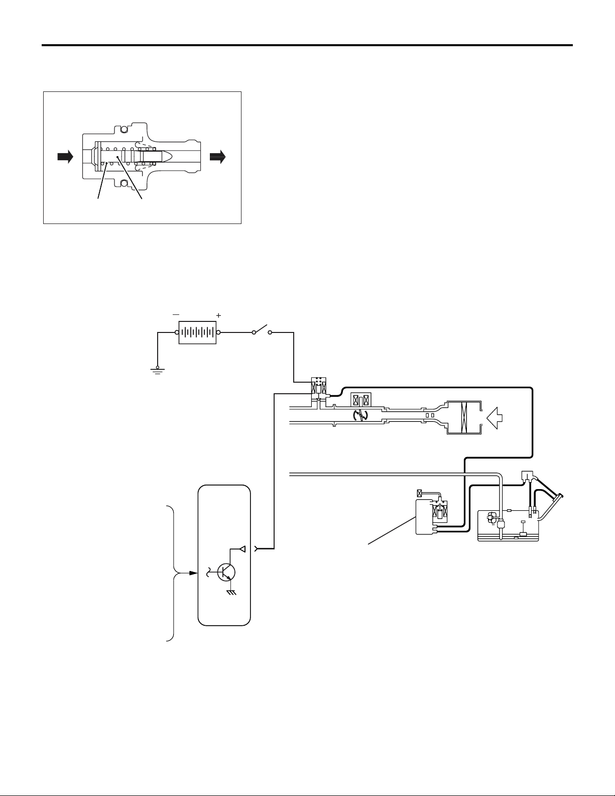
POSITIVE CRANKCASE VENTILATION (PCV)
VALVE
PCV valve lifts the plunger according to negative pressure in
the intake manifold to create appropriate ventilation for the
crankcase.
To intake
manifold
17-11
Spring
Plunger
AK602324 AC
EVAPORATIVE EMISSION CONTROL SYSTEM
Battery
MFI relay
Evaporative emission
purge solenoid
M2171000200147
Mass airflow sensor
Intake air temperature sensor
Manifold absolute pressure
sensor
Engine coolant temperature
sensor
Throttle position sensor
Crankshaft position sensor
ECM
HC (hydrocarbon) generated in the fuel tank are
adsorbed by the active carbon in the canister and
stored. HC stored in the canister is introduced to the
intake manifold when engine is in operation where it
is mixed with intake air and combusted. ECM intro
-
duces optimum HC amount according to driving con-
Evaporative emission
canister
AK604143
AB
ditions and so performs duty control on the
evaporative emission purge solenoid. Also, the evap
orative emission purge solenoid is closed during
deceleration or immediately after engine start to
restrict change in air-fuel ratio and prevent engine
from stalling.
-
Page 30
17-12
To intake manifold
To canister
B
A
AK604745
ENGINE AND EMISSION CONTROL
EMISSION CONTROL
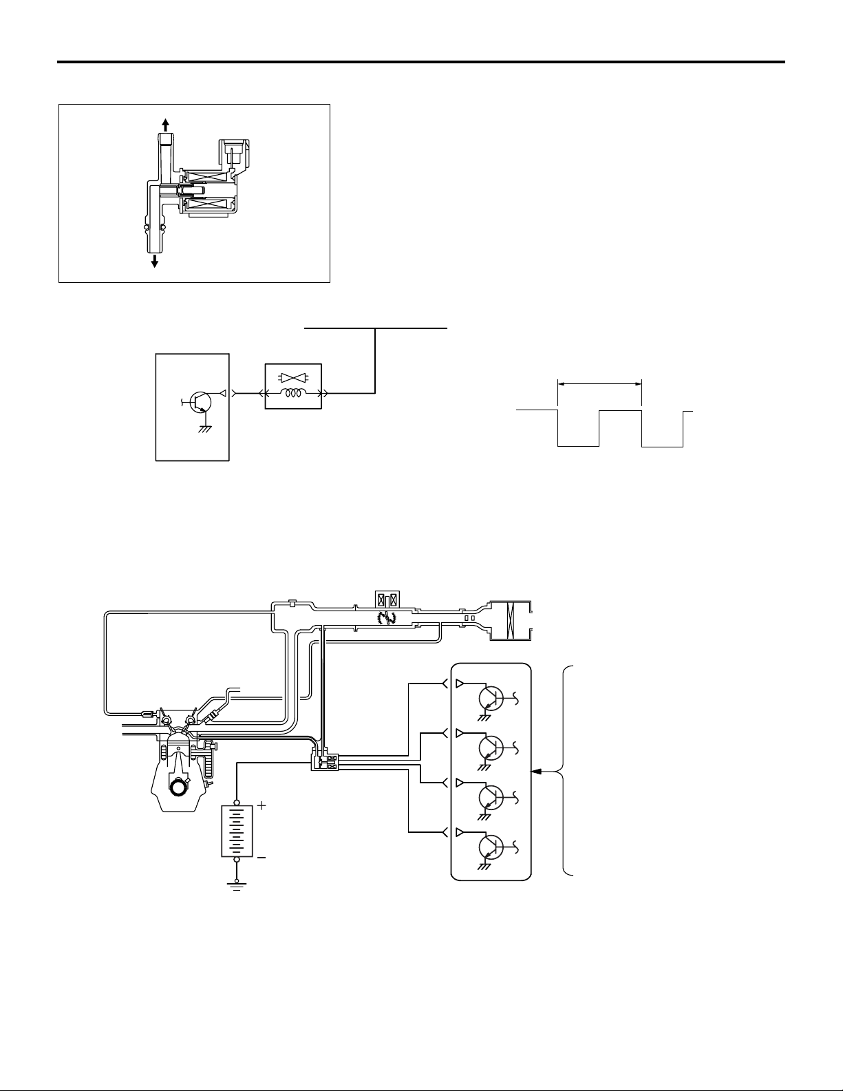
EVAPORATIVE EMISSION PURGE SOLENOID
An evaporative emission purge solenoid is installed in the
intake manifold.The evaporative emission purge solenoid con
trols the intake volume of fuel vapor gas from the canister. The
evaporative emission purge solenoid is a duty control type
solenoid valve. When current is not passing through the coil,
nipple A is kept airtight and fuel vapor gas cannot be sucked in.
When current passes through the coil, air can pass between
nipple A and B and fuel vapor gas is sucked in. ECM changes
the ON duty ratio according to engine's operating condition to
AC
control the intake volume of fuel vapor gas.
From MFI relay
-
100 ms
Evaporative
emission
purge solenoid
ECM
12V
0V
ON
EXHAUST GAS RECIRCULATION (EGR) SYSTEM <California>
EGR valve
(stepper motor)
OFF
AK602245AD
M2171000300122
Mass airflow sensor
Intake air temperature sensor
Manifold absolute
pressure sensor
Engine coolant
temperature sensor
Battery
When the combustion gas temperature becomes
high, generation of the environment polluting NOx
(nitrogen oxides) increases rapidly. EGR system is
used to decrease the volume of NOx generated.
EGR system re-circulates exhaust gas inside the
intake manifold. It increases specific heat of the com
bustion gases and reduces combustion speed to
Throttle position sensor
Crankshaft position sensor
ECM
AK502987AE
lower the combustion temperature and reduce the
volume of NOx generated. ECM calculates the EGR
introduction volume according to engine operating
conditions and controls the EGR valve opening angle
at optimum. Also, immediately after the ignition
switch ON signal is input, it drives fully closed step
per motor and performs initialization.
-
Page 31
Outlet
Inlet
Coil
ENGINE AND EMISSION CONTROL
EMISSION CONTROL
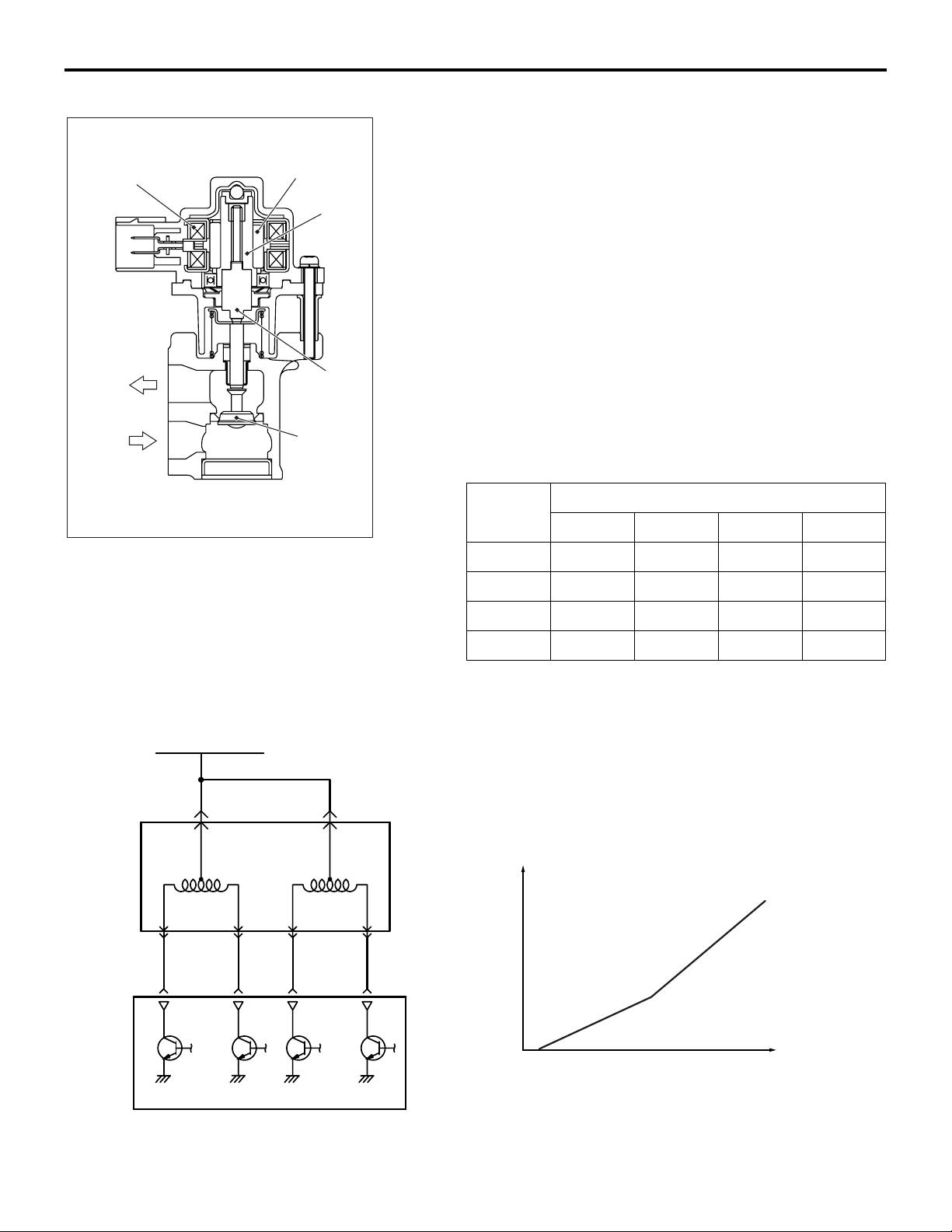
EXHAUST GAS RECIRCULATION (EGR) VALVE
An EGR valve is installed in the EGR valve support.The EGR
valve controls EGR flow volume using the stepper motor
Magnet
Rotor
Shaft
Valve
method and reduces exhaust gas (NOx) and fuel consumption.
The EGR valve drives the stepper motor based on the signal
from ECM. When stepper motor rotor turns in clockwise or
anti-clockwise direction, the shaft fitted with a rotor and a screw
expands and contracts and the movement of the shaft causes
the valve to go up and down. Thus, EGR path gap is controlled
minutely. The stepper motor turns 15
motor turns forward or back only up to the angle dictated by the
number of pulse signals (number of steps) from the ECM. In
other words, increase and decrease of the EGR flow volume
depends on the number of signals (number of steps) from
ECM. ECM changes current flow to the 4 coils (A, B, C, D) in
the stepper motor in sequence according to the phase pattern
in the following chart in order to turn the stepper motor rotor.
Open valve changes phase in order of 0
valve changes phase in order of 3
17-13
° per step. The stepper
→ 1 → 2 → 3 → 0. Close
→ 2 → 1 → 0 → 3.
From MFI relay
Coil
A
CoilBCoil
C
AK604144
EGR valve
(stepper motor)
AB
Coil
D
Phase
number
Stepper motor coil
Coil A Coil B Coil C Coil D
0 ON OFF OFF ON
1 ON OFF ON OFF
2 OFF ON ON OFF
3 OFF ON OFF ON
Flow rate
ECM
Step
AK604145
AB
Page 32
17-14
ENGINE AND EMISSION CONTROL
EMISSION CONTROL
EMISSION REDUCTION SYSTEMS
These decrease CO, HC and NOx in the exhaust
gases and consist of air-fuel ratio feedback control
and catalytic converter.
1. AIR-FUEL RATIO FEEDBACK CONTROL
Refer to GROUP 13A − Fuel Injection Control P.13A-29.
2. CATALYTIC CONVERTER
<Except for California>
Catalytic converter
<California>
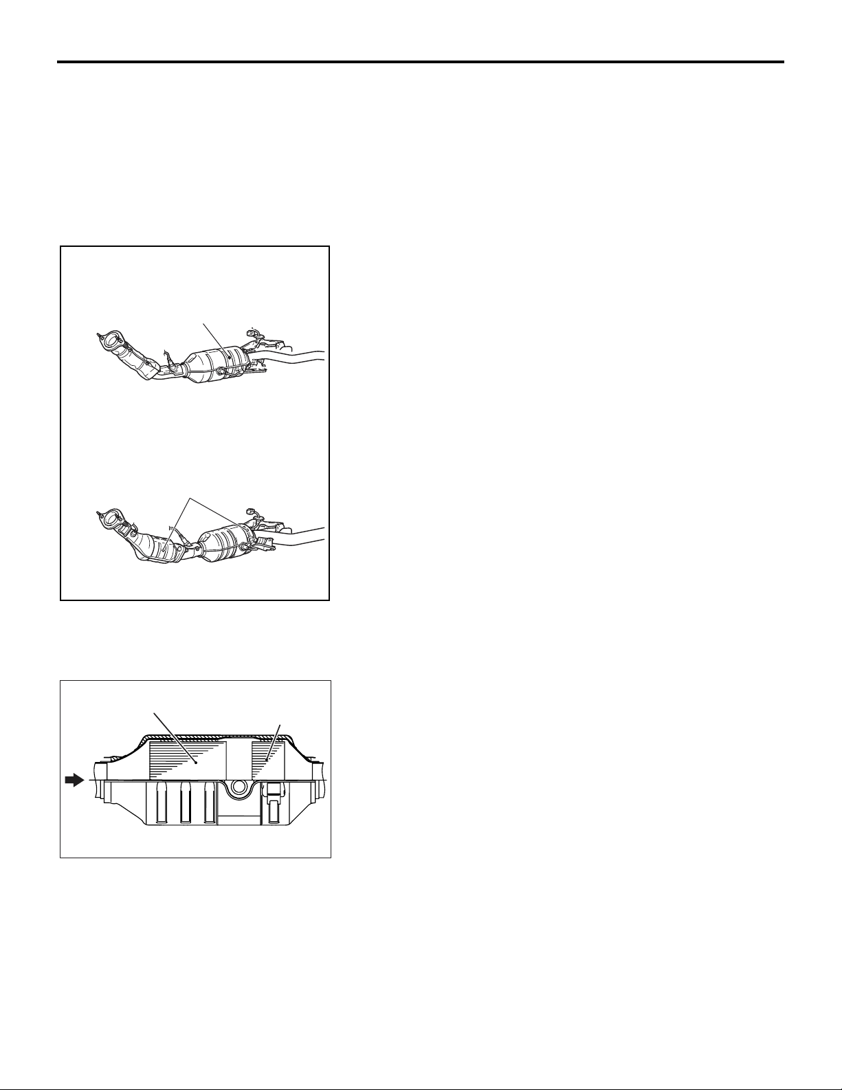
Catalytic converter is installed in the center of exhaust pipe
below the floor and in the front of exhaust pipe <California>.
Based on appropriate air-fuel ratio feedback from oxygen sen
sor, CO and HC are oxidized and NOx is reduced. Catalytic
converter is a monolith with beehive design with catalysts on
the unit surface. It is protected by a thermally insulating mat
and enclosed in a shell.
M2171000800064
-
Exhaust
gas
Catalytic converter
HC trap catalyst
AK604146
Three-way catalyst
AK604147
AB
AB
3. HC TRAP CATALYTIC CONVERTER
<California>
The HC trap catalytic converter is installed in the center of
exhaust pipe below the floor. The HC trap catalytic converter
consists of the HC trap catalyst and the three-way catalysts,
which are the monolith type; the catalyst element is attached to
the honeycomb catalyst surface. The HC trap catalyst and the
three-way catalysts are held by the heat-insulating mat and
installed in the shell. The HC trap catalyst temporarily absorbs
the exhaust HC from the engine within the temperature range
in which the three-way catalyst is not activated, and prevents
the exhaust HC from releasing outside the vehicle. After that,
the HC trap catalyst temperature rises and releases the
absorbed HC. The released HC is burnt out in the downstream
three-way catalyst.
Page 33
Heated oxygen sensor (3rd)
HC trap catalytic converter
ENGINE AND EMISSION CONTROL
EMISSION CONTROL
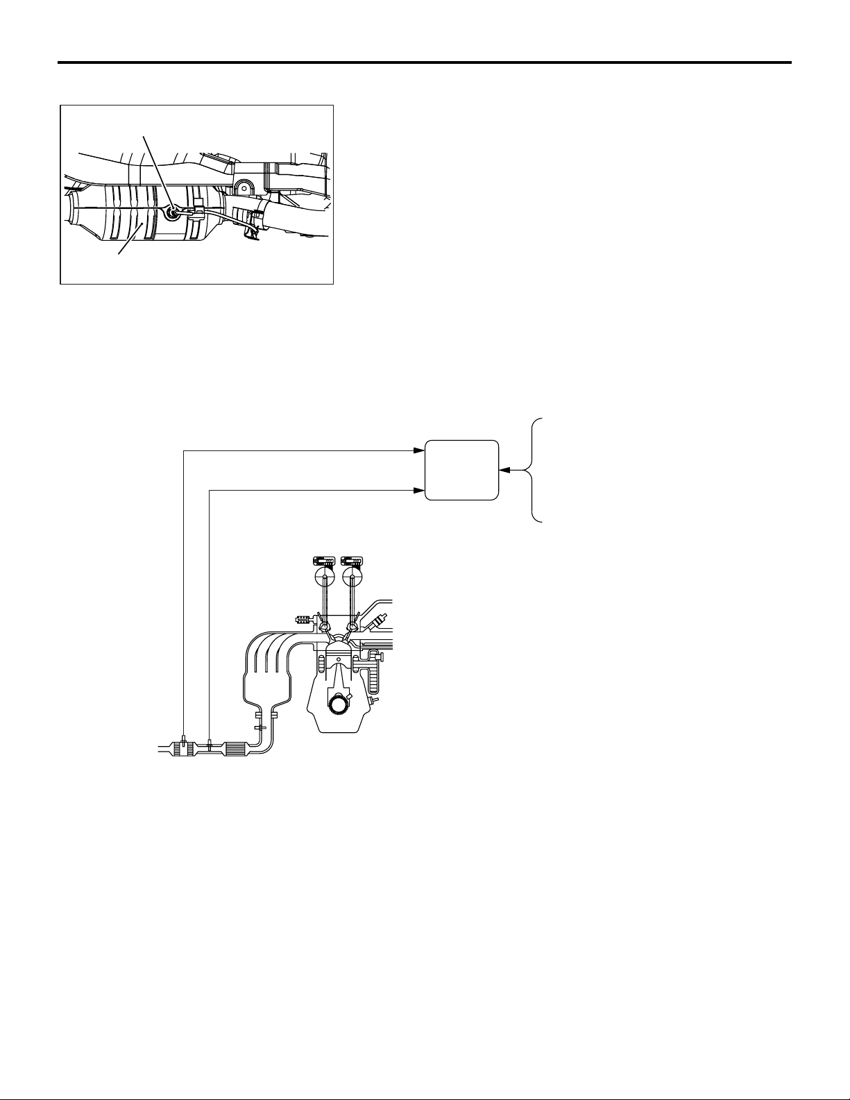
HEATED OXYGEN SENSOR (3RD)
The heated oxygen sensor (3rd) is installed to the HC trap catalytic converter. The heated oxygen sensor (3rd) detects the
oxygen density of the exhaust gas and outputs the voltage to
the ECM in accordance with the oxygen density.
The ECM uses this output voltage to detect the deterioration of
the HC trap catalytic converter. The structure of the heated oxy
gen sensor (3rd) is the same as that of the heated oxygen sensor (rear) installed in the exhaust pipe.
AK604553
AB
HC TRAP CATALYTIC CONVERTER
DETERIORATION MONITOR
17-15
-
Heated oxygen sensor (3rd)
Heated oxygen sensor (rear)
The ECM detects the deterioration of the HC trap catalytic converter.
When reaching the certain operating range, the ECM begins
monitoring the difference in the feedback time between the
heated oxygen sensor (rear) on the upstream of the HC trap
catalyst and the heated oxygen sensor (3rd) on the down
stream of the HC trap catalyst. This monitoring allows the ECM
to detect the deterioration of the HC trap catalytic converter.
ECM
Engine coolant
temperature sensor
Accelerator pedal
position sensor
Crankshaft position sensor
AK604148 AB
-
Page 34

NOTES
Page 35

GROUP 16
ENGINE
ELECTRICAL
CONTENTS
16-1
STARTER MOTOR . . . . . . . . . . . . . . 16-2
ALTERNATOR . . . . . . . . . . . . . . . . . . 16-2
IGNITION COIL . . . . . . . . . . . . . . . . . . 16-2
SPARK PLUG . . . . . . . . . . . . . . . . . . . 16-3
Page 36
16-2
ENGINE ELECTRICAL
STARTER MOTOR
AK603841
STARTER MOTOR
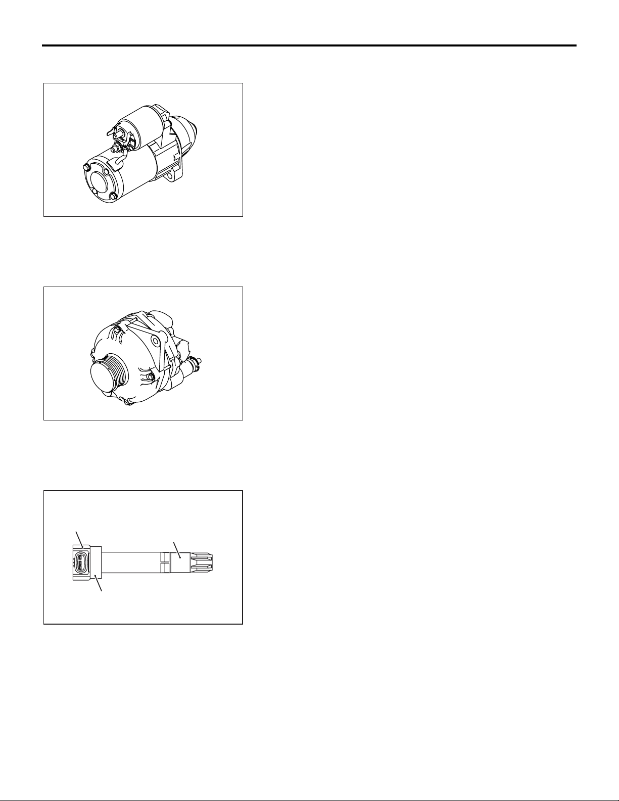
M2161002000160
The starter motor is a reduction drive planetary gear type.
ALTERNATOR
M2162001000126
The alternator is a battery detection type.
It uses a pulley with a one-way clutch.
Coil
Rain cover
Plug boots
AK603842
AK602597
IGNITION COIL
M2163001000174
The ignition coil is a plug-top type.
AC
Page 37
ENGINE ELECTRICAL
SPARK PLUG
16-3
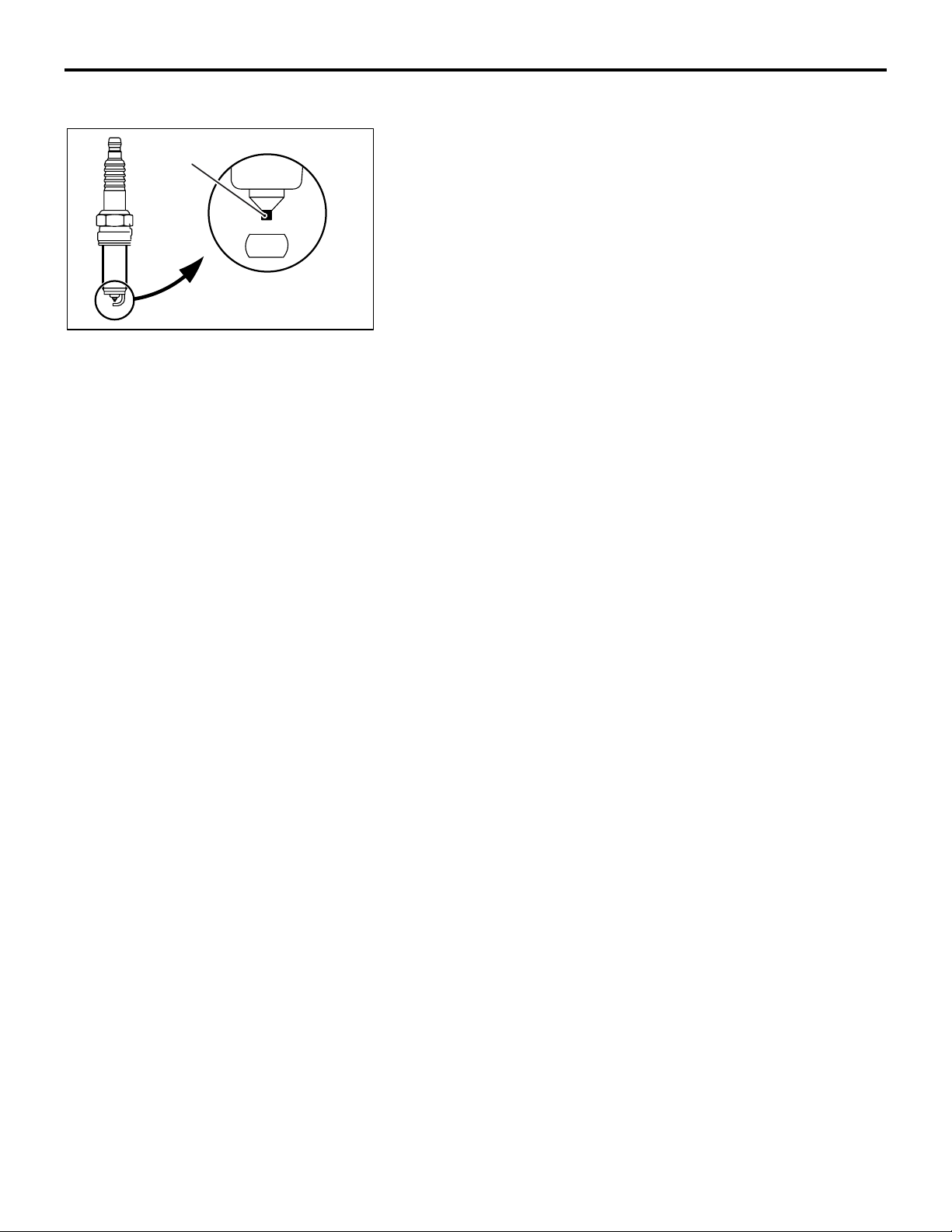
Iridium
SPARK PLUG
M2163005000068
Iridium-tipped spark plugs are used.
AK604562AB
Page 38

NOTES
Page 39

GROUP 15
INTAKE AND
EXHAUST
CONTENTS
15-1
AIR DUCT AND AIR CLEANER . . . . 15-2
INTAKE MANIFOLD . . . . . . . . . . . . . 15-3
EXHAUST MANIFOLD . . . . . . . . . . . . 15-4
EXHAUST PIPE AND MUFFLER . . . . 15-4
Page 40
15-2
INTAKE AND EXHAUST
AIR DUCT AND AIR CLEANER
AIR DUCT AND AIR CLEANER
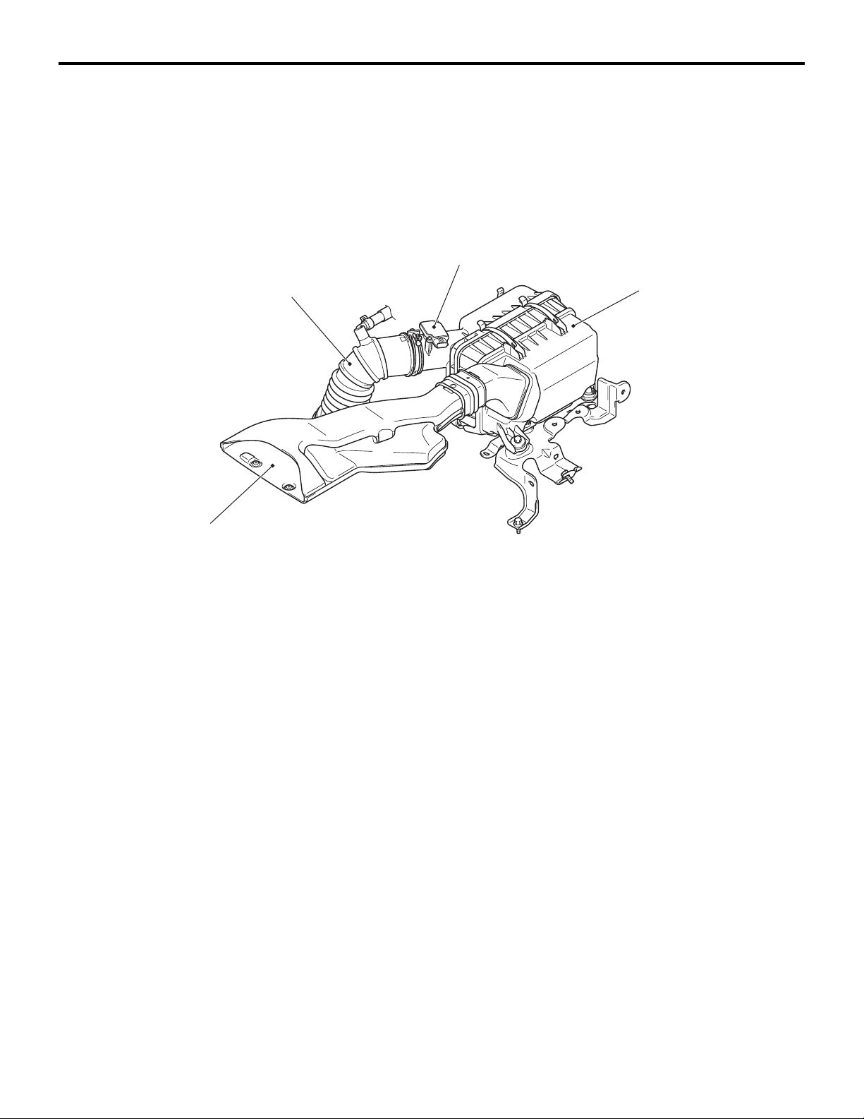
A front air intake system that actively sucks cooling
air from the front through the top of the radiator has
been adopted in order to improve engine perfor
mance and reduce air intake noise.
CONSTRUCTION DIAGRAM
Air cleaner intake hose
-
M2150004000656
Mass airflow sensor
Air cleaner assembly
Air cleaner intake duct
AC608342
AB
Page 41
INTAKE AND EXHAUST
INTAKE MANIFOLD
15-3
INTAKE MANIFOLD
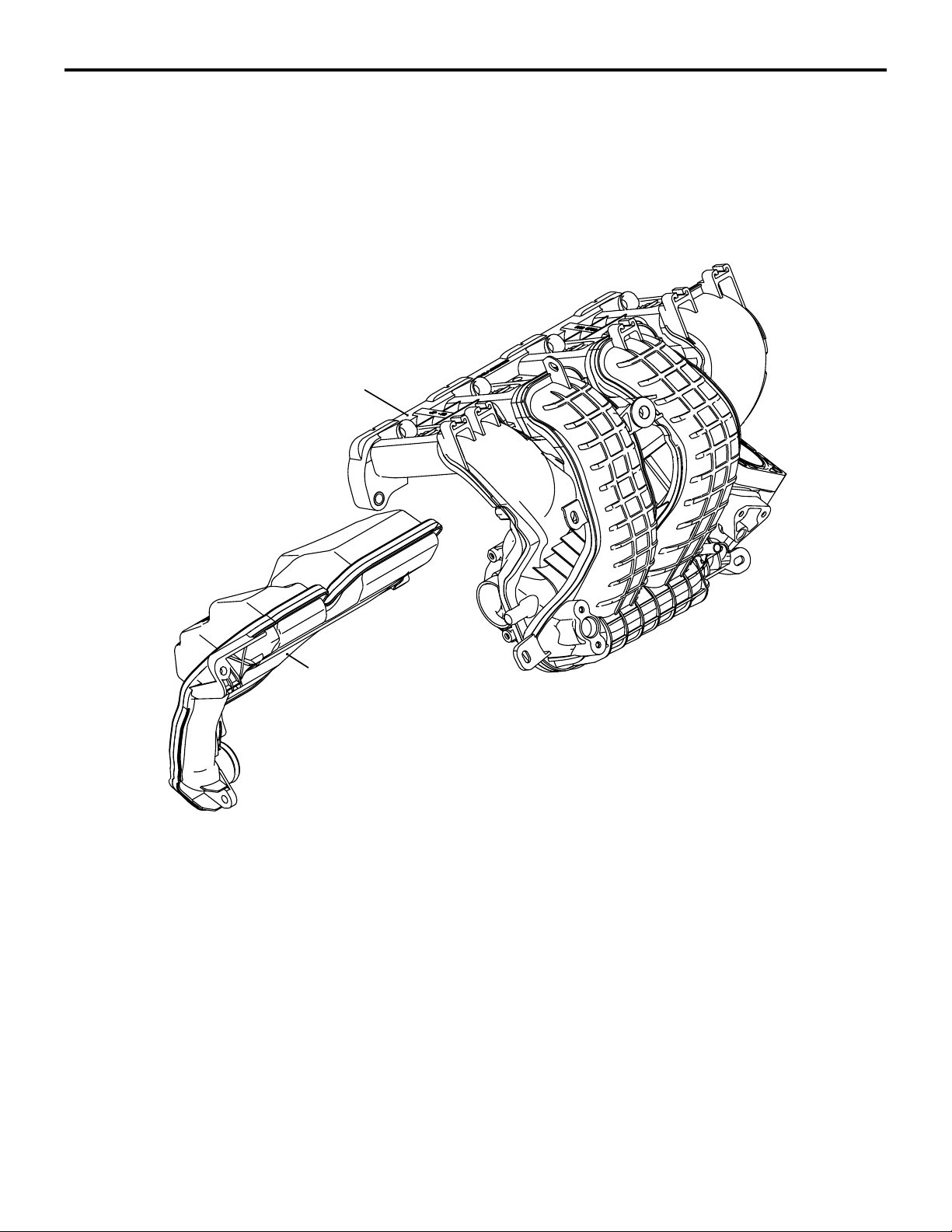
The intake manifold is made of plastic for weight
reduction, and the surface roughness of the inner
walls of the ports has been improved to reduce
intake resistance.
Intake manifold
M2150005000239
Air intake plenum
tank resonator
AK502555
AD
Page 42
15-4
INTAKE AND EXHAUST
EXHAUST MANIFOLD
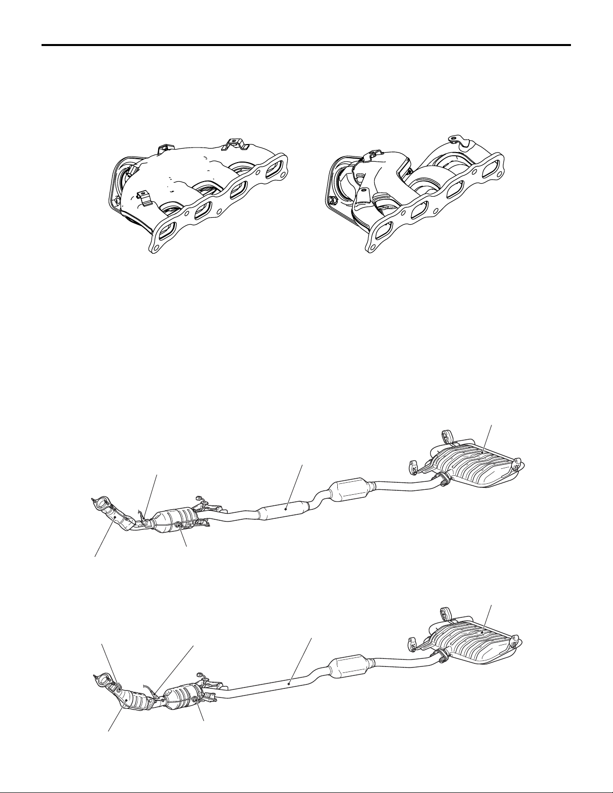
EXHAUST MANIFOLD
<California>
A clamshell type exhaust manifold is used.
EXHAUST PIPE AND MUFFLER
The exhaust system is composed of the front
exhaust pipe, center exhaust pipe, and main muffler,
and it has the following characteristics.
M2150006000566
<Except California>
A SUS pipe type exhaust manifold is used.
<Except CALIFORNIA><CALIFORNIA>
AK603623
M2150003000783
• Fewer, more environmentally-friendly rubber
hangers to reduce vibration from exhaust system.
• Straighter exhaust pipe to reduce noise.
AB
CONSTRUCTION DIAGRAM
<Except for California>
Heated oxygen sensor (front)
Heated oxygen sensor (rear)
Front exhaust pipe
<Vehicles for California>
Heated oxygen
sensor (front)
Heated oxygen
sensor (rear)
Center exhaust pipe
Center exhaust pipe
Main muffler
AC608352
Main muffler
AB
Front exhaust pipe
Heated oxygen sensor (3rd)
AC608488
AB
Page 43

GROUP 14
ENGINE COOLING
CONTENTS
14-1
GENERAL INFORMATION . . . . . . . . 14-2
WATER PASSAGE . . . . . . . . . . . . . . 14-3
WATER PUMP . . . . . . . . . . . . . . . . . . 14-3
Page 44

14-2
ENGINE COOLING
GENERAL INFORMATION
GENERAL INFORMATION
M2140000100780
The cooling system is a water-cooled pressurized,
forced circulation type which offers the following fea
tures.
• To stabilize engine coolant temperature, the thermostat is located at the coolant inlet port from the
radiator.
SPECIFICATIONS
Item Specification
Cooling method Water-cooled pressurized, forced
Radiator Type Pressurized corrugate type
Performance kJ/h (kcal/h) 222,480 (53,148)
Water pump Type Centrifugal impeller
Drive method Drive belt
Thermostat Type Wax pellet with jiggle valve
Valve open temperature ° C (° F) 82 (180)
• To improve engine cooling performance and save
-
weight, a plastic tank and aluminum radiator fins
are used.
circulation with electrical fan
CONSTRUCTION DIAGRAM
Radiator fan motor
Transmission oil
cooler line hose
and tube assembly
Radiator lower hose
Radiator assembly
Cooling fan shroud
Radiator upper hose
assembly
Radiator condenser
tank assembly
Condenser fan motor
AC608448
AB
Page 45
ENGINE COOLING
WATER PASSAGE
14-3
WATER PASSAGE
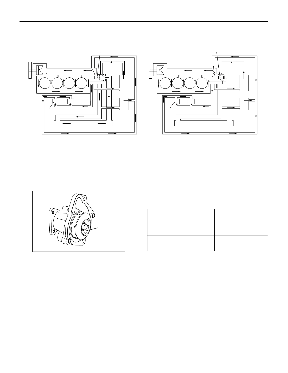
<Hot>
Water pump
EGR
Throttle body
Radiator
NOTE: EGR: Exhaust Gas Recirculation <California only>
CVT: Continuously Variable Transmission
Thermostat
Heater
CVT oil
cooler
<Cold>
Water pump
Throttle body
EGR
Radiator
Thermostat
M2140004000172
Heater
CVT oil
cooler
AK603624
AB
Impeller
AK503034
WATER PUMP
The water pump is the centrifugal, impeller type that
is installed in front of the cylinder block. It is driven by
the drive belt.
Item Specifications
Discharge volume L/min 185
Impeller diameter mm (in) 62 (2.4)
Pulley outer diameter mm
AD
(in)
M2140003000168
137 (5.4)
Page 46

NOTES
Page 47

13B-1
GROUP 13B
FUEL SUPPLY
CONTENTS
GENERAL INFORMATION . . . . . . . . 13B-2 FUEL TANK . . . . . . . . . . . . . . . . . . . . 13B-3
Page 48
13B-2
FUEL SUPPLY
GENERAL INFORMATION
GENERAL INFORMATION
.
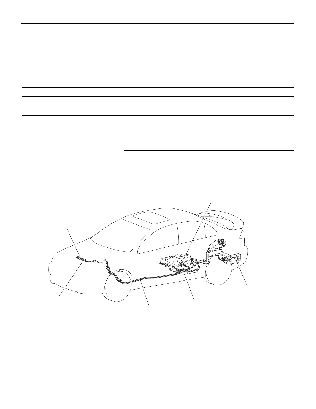
The fuel system consists of the following components:
• Fuel injector
• Fuel rail
• Fuel pipe
• Fuel tank
• Fuel pump module
• Evaporative emission canister
SPECIFICATIONS
Item Specification
Fuel tank capacity dm3 (gal)
59 (15.5)
Fuel pump type Electric
Fuel filter type Cartridge (incorporates fuel pump module)
Fuel return system Returnless
Fuel pump pressure regulator pressure kPa (psi) 324 (46)
Fuel injector Type Elector-magnetic
Quantity 4
Evaporative emission control system Canister
CONSTRUCTION DIAGRAM
M2134000100833
Fuel rail
Fuel injector
Fuel pipe
This fuel system is designed with consideration for
global environment protection to ensure safety at a
collision, reduce weight, and improve reliability and
quality. This system has the following features:
• A quick-joint connector of a plastic tube is used
for the fuel high-pressure hoses in the engine
compartment to reduce the permeation of fuel
evaporative emission.
Fuel tank
Evaporative
emission
Fuel pump module
canister
AC610224
AB
• The surface of underfloor fuel pipes is coated
with 1-mm thickness of plastic to improve resis
-
tance to corrosion and chipping.
• A returnless fuel system eliminates returned fuel
from the engine. The heat that fuel receives from
the engine is reduced, minimizing fuel tempera
ture in the fuel tank and controlling the amount of
evaporated gas.
Page 49
FUEL SUPPLY
FUEL TANK
13B-3
FUEL TANK
.
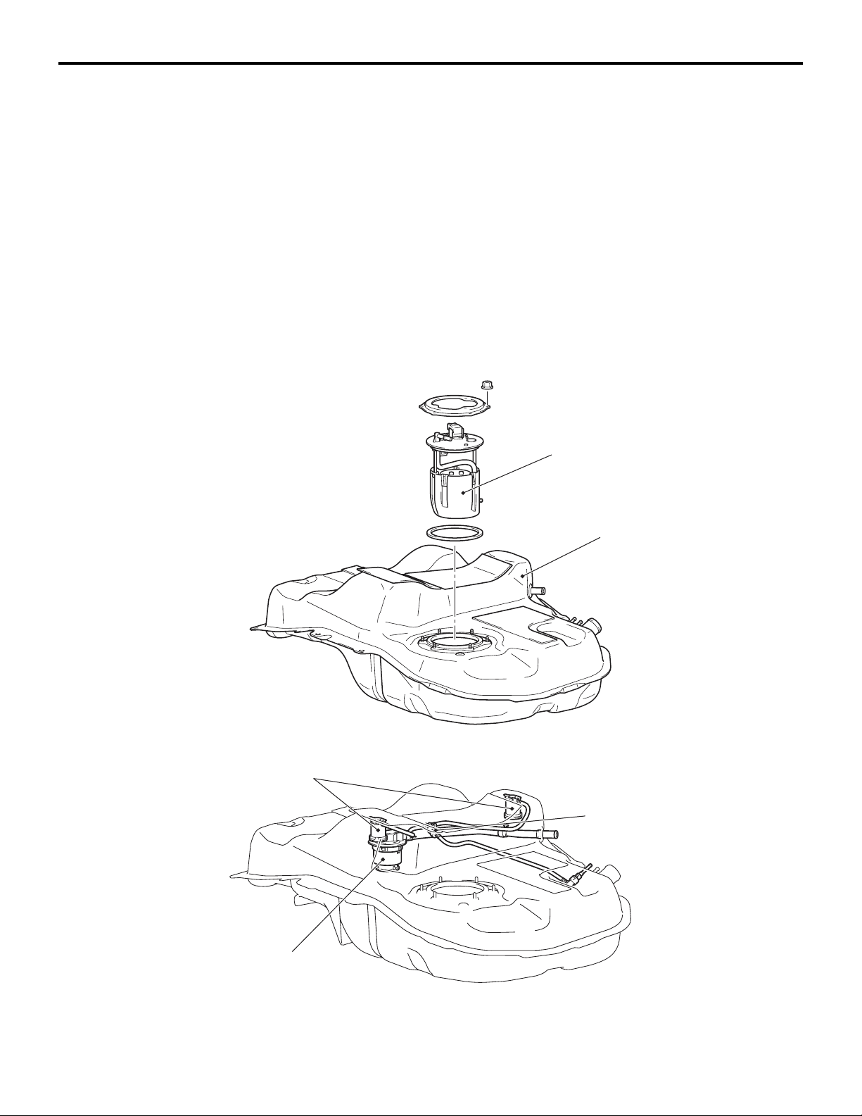
The fuel tank assembly consists of the fuel pump
module, the fuel tank, and so on, and features the
following characteristics:
• The fuel tank is mounted underneath the second
seat to improve safety at a collision.
• The fuel tank itself is made of a pre-coat zinc
alloy galvanised steel sheet that contains no
lead.
• The capacity of the fuel tank is 59 dm3 (15.5 gal)
to meet long-distance drives.
CONSTRUCTION DIAGRAM
M2134001000817
• The fuel cut-off valve, fuel tank leveling valve and
fuel tube have been installed using in-tank con
struction to reduce the amount of evaporated fuel
from hoses.
The fuel pump module consists of the following components:
• Fuel pump
• Fuel level sensor
• Fuel filter
• Fuel pump pressure regulator
• Fuel tank differential pressure sensor
• Fuel tank temperature sensor
Fuel pump module
Fuel cut-off valve
Fuel tank
Fuel check valve
AC610225
AB
Leveling valve
AC610226
AC
Page 50

NOTES
Page 51

GROUP 13A
MULTIPORT FUEL
SYSTEM (MFI)
CONTENTS
13A-1
GENERAL DESCRIPTION. . . . . . . . . 13A-2
CONTROL UNIT. . . . . . . . . . . . . . . . . 13A-6
SENSOR. . . . . . . . . . . . . . . . . . . . . . . 13A-8
ACTUATOR . . . . . . . . . . . . . . . . . . . . 13A-23
FUEL INJECTION CONTROL . . . . . . 13A-29
IGNITION TIMING AND CONTROL FOR
CURRENT CARRYING TIME . . . . . . 13A-35
THROTTLE VALVE OPENING ANGLE
CONTROL AND IDLE SPEED
CONTROL . . . . . . . . . . . . . . . . . . . . . 13A-38
MIVEC (Mitsubishi Innovative Valve
Timing Electronic Control System). 13A-40
MULTIPORT FUEL INJECTION (MFI)
RELAY CONTROL. . . . . . . . . . . . . . . 13A-45
FUEL PUMP RELAY CONTROL . . . . 13A-46
STARTER RELAY CONTROL. . . . . . 13A-47
HEATED OXYGEN SENSOR HEATER
CONTROL. . . . . . . . . . . . . . . . . . . . . . 13A-49
A/C COMPRESSOR RELAY
CONTROL. . . . . . . . . . . . . . . . . . . . . . 13A-50
GENERATOR CONTROL. . . . . . . . . . 13A-51
EVAPORATIVE EMISSION CONTROL
SYSTEM INCORRECT PURGE FLOW
MONITOR . . . . . . . . . . . . . . . . . . . . . . 13A-52
EXHAUST GAS RECIRCULATION
CONTROL. . . . . . . . . . . . . . . . . . . . . . 13A-53
CONTROLLER AREA NETWORK
(CAN) . . . . . . . . . . . . . . . . . . . . . . . . . 13A-53
EVAPORATIVE EMISSION PURGE
CONTROL. . . . . . . . . . . . . . . . . . . . . . 13A-53
HC TRAP CATALYTIC CONVERTER
DETERIORATION MONITOR. . . . . . . 13A-53
ON-BOARD DIAGNOSTICS. . . . . . . . 13A-53
Page 52

13A-2
MULTIPORT FUEL SYSTEM (MFI)
GENERAL DESCRIPTION
GENERAL DESCRIPTION
M2132000101283
Although the control systems are basically the same as those of 2.4L engine used in the GALANT, the following improvements have been added.
Improvement / Additions Remark
MIVEC, continuously and variably control the intake
valve timing and exhaust valve timing, is used.
Addition of heated oxygen sensor (3rd)
<California>
System optimally control the timing of the intake
valve and exhaust valve in accordance with the
engine speed and load.
Detection of the HC trap catalyst malfunction.
Page 53
MULTIPORT FUEL SYSTEM (MFI)
GENERAL DESCRIPTION
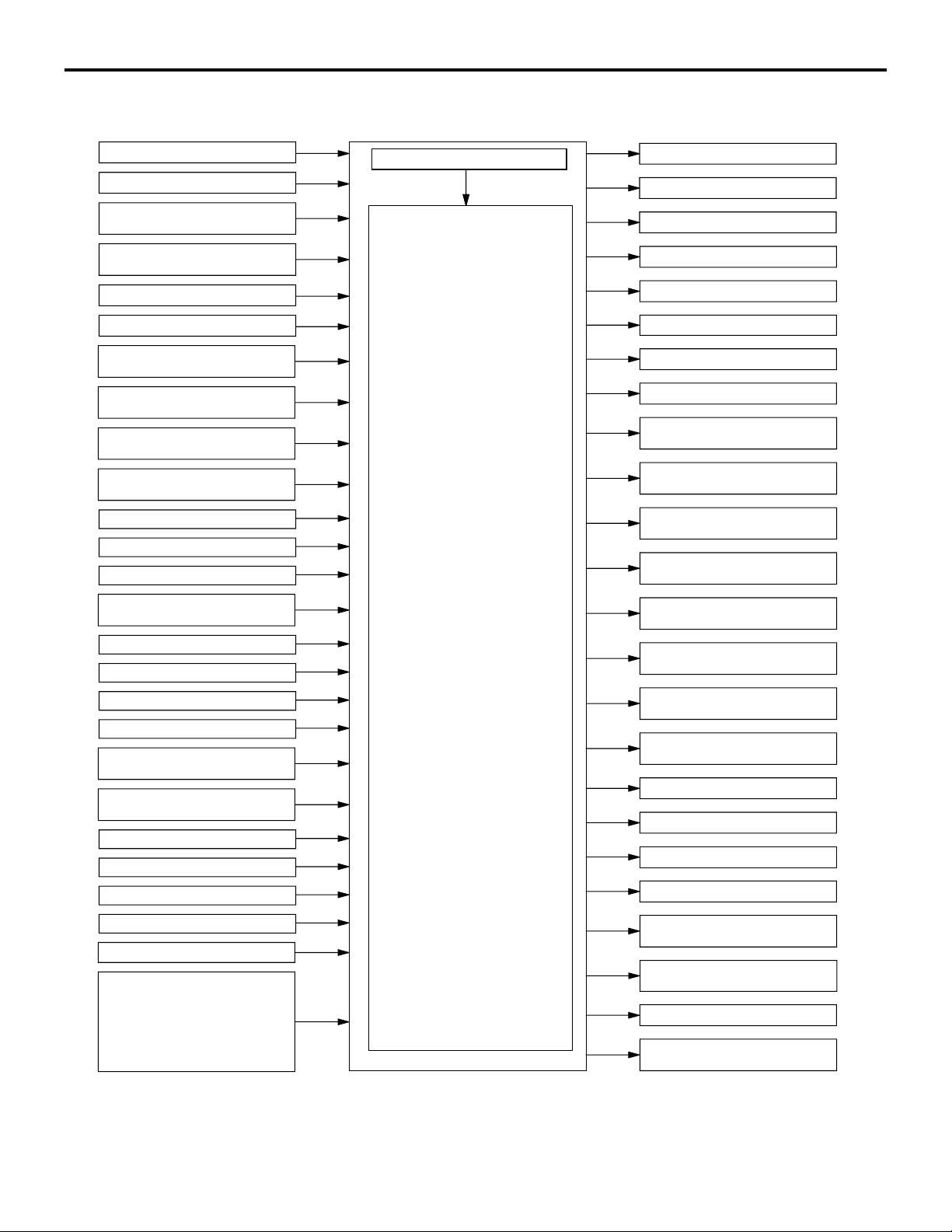
System Block Diagram
Sensor, switch Engine control module (ECM) Actuator
Mass airflow sensor
Intake air temperature sensor
Manifold absolute pressure
sensor
Barometric pressure sensor
Engine control unit
13A-3
No. 1 injector
No. 2 injector
No. 3 injector
Engine coolant temperature
sensor
Throttle position sensor (main)
Throttle position sensor (sub)
Accelerator pedal position
sensor (main)
Accelerator pedal position
sensor (sub)
Intake camshaft position
sensor
Exhaust camshaft position
sensor
Crankshaft position sensor
Heated oxygen sensor (front)
Heated oxygen sensor (rear)
Heated oxygen sensor
(3rd)*
Knock sensor
Generator FR terminal
Generator L terminal
Engine oil pressure switch
Power steering pressure
switch
Fuel tank differential pressure
sensor
Fuel tank temperature sensor
Vehicle speed sensor <M/T>
Ignition switch-IG
Ignition switch-ST
Power supply
CAN communication
(input signal)
· A/C switch
· Vehicle speed <CVT>
· Fuel level sensor
· Transmission range switch
<CVT>
NOTE
*1: California
[1] Fuel injection control
[2] Ignition timing control
[3] Throttle valve opening angle
control and idle speed control
MIVEC (Mitsubishi Innovative
[4]
Valve timing Electronic Control
system)
[5] Power supply control
(Power supply to sensor,
actuator)
[6] Fuel pump relay control
[7] Starter relay control
[8] Heated oxygen sensor heater
control
[9] A/C compressor relay control
[10] Generator control
[11] Evaporative emission purge
control
[12] EGR control
[13] Diagnosis output
[14] RAM data transmission
No. 4 injector
No. 1 ignition coil
No. 2 ignition coi
No. 3 ignition coi
No. 4 ignition coi
Throttle actuator control
motor
Heated oxygen sensor (front)
heater
Heated oxygen sensor (rear)
heater
Heated oxygen sensor (3rd)
heater*
Intake engine oil control
valve
Exhaust engine oil control
valve
Multiport fuel injection (MFI)
relay
Throttle actuator control
motor relay
A/C compressor relay
Fuel pump relay
Starter relay
Generator G terminal
Evaporative emission purge
solenoid
Evaporative emission ventilation
solenoid
EGR valve (stepper motor)*
CAN communication
(output signal)
AK604116
AB
Page 54
13A-4
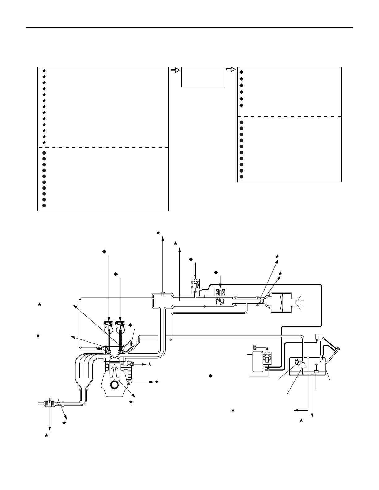
Control System Diagram
<Except for California>
MULTIPORT FUEL SYSTEM (MFI)
GENERAL DESCRIPTION
Sense Act
1 Mass airflow sensor
2 Intake air temperature sensor
3 Throttle position sensor (main/sub)
4 Manifold absolute pressure sensor
5 Engine coolant temperature sensor
6 Intake camshaft position sensor
7 Exhaust camshaft position sensor
8 Crankshaft position sensor
9 Knock sensor
10 Heated oxygen sensor (front)
11 Heated oxygen sensor (rear)
12 Fuel tank differential pressure sensor
13 Fuel tank temperature sensor
Accelerator pedal position sensor (main/sub)
Engine oil pressure switch
Power steering pressure switch
Generator FR terminal
Generator L terminal
Vehicle speed sensor <M/T>
Ignition switch-IG
Ignition switch-ST
Power supply
CAN communication (input signal)
4 Manifold absolute pressure sensor
Decide
ECM
(with barometric
pressure sensor)
1 Intake engine oil control valve
2 Exhaust engine oil control valve
3 Throttle actuator control motor
4 Injector
5 Evaporative emission purge solenoid
6 Evaporative emission ventilation
solenoid
Ignition coil, ignition power transistor
Multiport fuel injection (MFI) relay
Fuel pump relay
Starter relay
Throttle actuator control motor relay
Generator G terminal
Heated oxygen sensor heater
A/C compressor relay
Diagnostic output
CAN communication (output signal)
6 Intake
camshaft
position
sensor
7 Exhaust
camshaft
position
sensor
10 Heated oxygen sensor (front)
11 Heated oxygen
sensor (rear)
2 Exhaust engine
oil control valve
1 Intake engine
oil control valve
4 Injector
8 Crankshaft position sensor
3 Throttle position
sensor (main/sub)
5 Evaporative emission
purge solenoid
5 Engine coolant
temperature sensor
9 Knock sensor
3 Throttle actuator
control motor
Evaporative
emission
canister
6 Evaporative
emission
ventilation
solenoid
12 Fuel tank differential
pressure sensor
2 Intake air
temperature sensor
1 Mass airflow sensor
Fuel pressure
regulator
Fuel pump
Air
inlet
Fuel tank
Fuel level
sensor
13 Fuel tank
temperature
sensor
AK604117
AB
Page 55
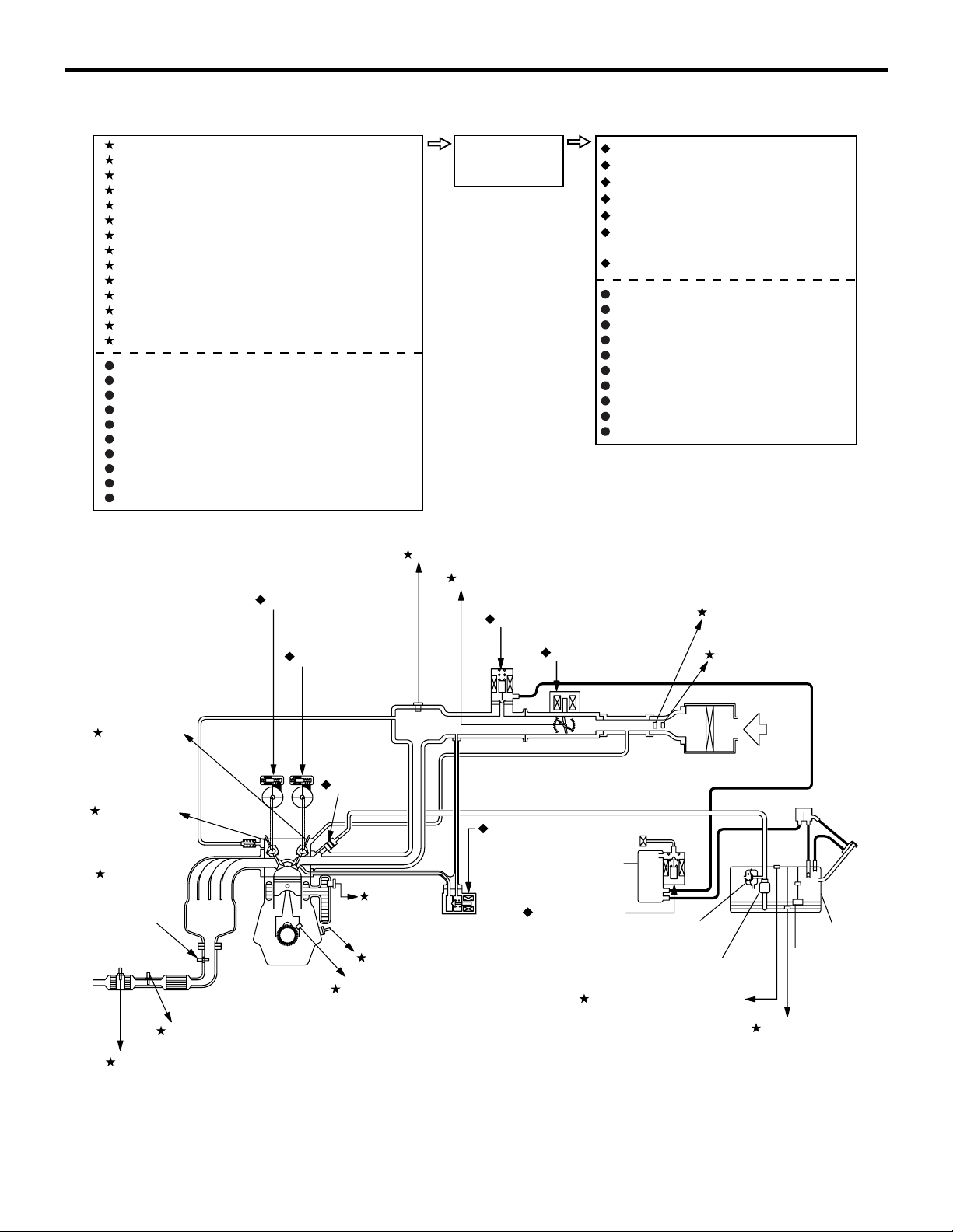
<California>
MULTIPORT FUEL SYSTEM (MFI)
GENERAL DESCRIPTION
13A-5
Sense Act
1 Mass airflow sensor
2 Intake air temperature sensor
3 Throttle position sensor (main/sub)
4 Manifold absolute pressure sensor
5 Engine coolant temperature sensor
6 Intake camshaft position sensor
7 Exhaust camshaft position sensor
8 Crankshaft position sensor
9 Knock sensor
10 Heated oxygen sensor (front)
11 Heated oxygen sensor (rear)
12 Heated oxygen sensor (3rd)
13 Fuel tank differential pressure sensor
14 Fuel tank temperature sensor
Accelerator pedal position sensor (main/sub)
Engine oil pressure switch
Power steering pressure switch
Generator FR terminal
Generator L terminal
Vehicle speed sensor <M/T>
Ignition switch-IG
Ignition switch-ST
Power supply
CAN communication (input signal)
2 Exhaust engine
oil control valve
1 Intake engine
oil control valve
Decide
ECM
(with barometric
pressure sensor)
4 Manifold absolute pressure sensor
3 Throttle position
sensor (main/sub)
5 Evaporative emission
purge solenoid
3 Throttle actuator
control motor
1 Intake engine oil control valve
2 Exhaust engine oil control valve
3 Throttle actuator control motor
4 Injector
5 Evaporative emission purge solenoid
6 Evaporative emission ventilation
solenoid
7 EGR valve (stepper motor)
Ignition coil, ignition power transistor
Multiport fuel injection (MFI) relay
Fuel pump relay
Starter relay
Throttle actuator control motor relay
Generator G terminal
Heated oxygen sensor heater
A/C compressor relay
Diagnostic output
CAN communication (output signal)
2 Intake air
temperature sensor
1 Mass airflow sensor
6 Intake
camshaft
position
sensor
7 Exhaust
camshaft
position
sensor
10 Heated
oxygen
sensor
(front)
11 Heated oxygen sensor (rear)
12 Heated oxygen sensor (3rd)
4 Injector
5 Engine
coolant
temperature
sensor
9 Knock sensor
8 Crankshaft position sensor
7 EGR valve
(stepper motor)
Evaporative
emission
canister
6 Evaporative
emission
ventilation
solenoid
Fuel pressure
regulator
Fuel pump
12 Fuel tank differential
pressure sensor
Air
inlet
Fuel tank
Fuel level
sensor
13 Fuel tank
temperature
sensor
AK604118
AB
Page 56
13A-6
MULTIPORT FUEL SYSTEM (MFI)
CONTROL UNIT
CONTROL UNIT
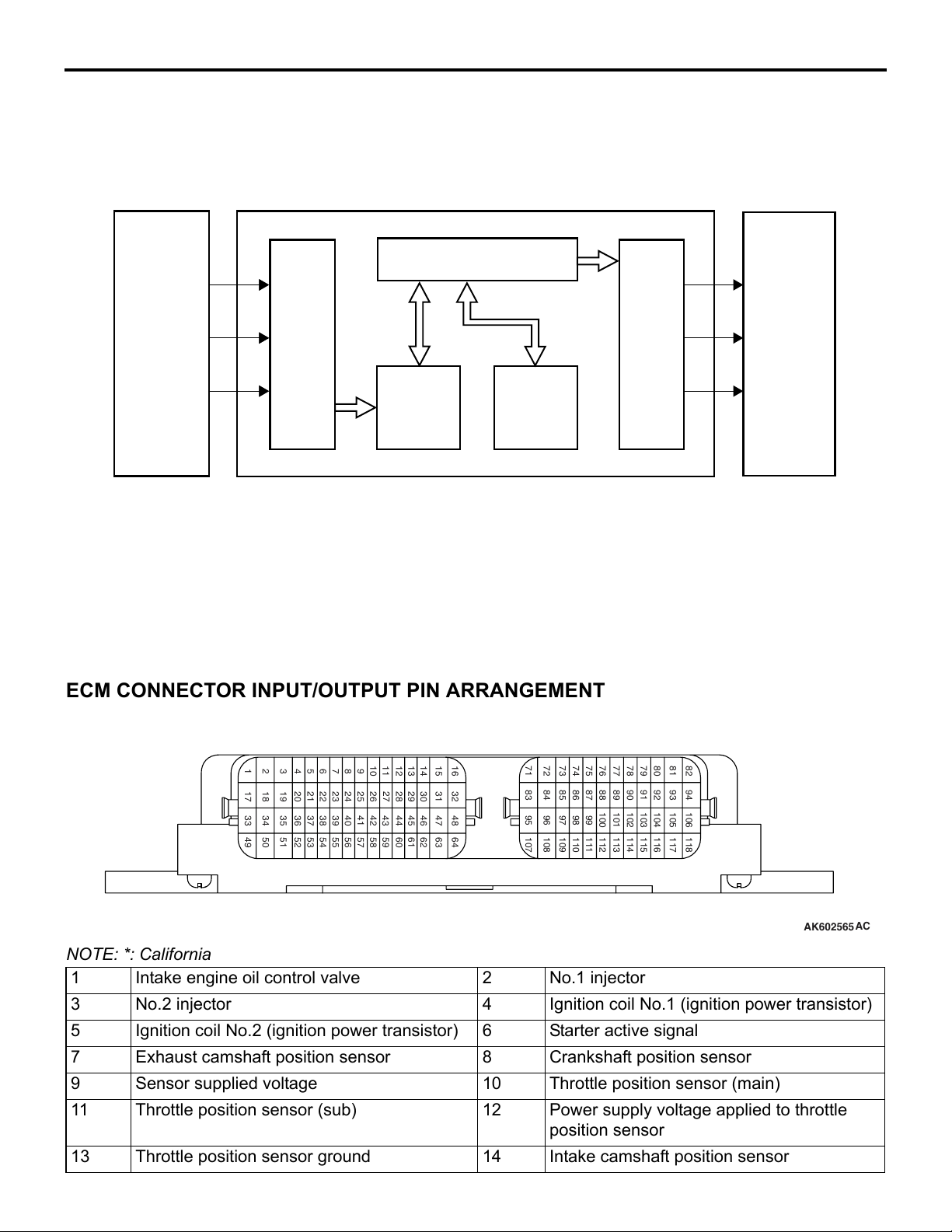
ENGINE CONTROL MODULE (ECM)
ECM
Microprocessor
Input
sensor
ECM is installed in the engine room. ECM judges
(calculates) the optimum control to deal with the con
stant minute changes in driving conditions based on
information input from the sensors and drives the
actuator. ECM is composed of 32-bit microprocessor
and Random Access Memory (RAM), Read Only
Memory (ROM) and Input /Output interface. ECM
Input
interface
RAM
M2132021500153
Output
interface
Output
actuator
ROM
AK604119
uses flash-memory ROM that allows re-writing of
data so that change and correction of control data is
possible using special tools. It also uses Electrically
Erasable Programmable Read Only Memory
(EEPROM) so that studied compensation data is not
deleted even if battery terminals are disconnected.
AB
ECM CONNECTOR INPUT/OUTPUT PIN ARRANGEMENT
91
929394
104
103
115
116
105
117
82
106
118
AK602565
123456789
1718192021
36
35
34
33
52
51
50
49
24
23
22
40
39
38
37
56
55
54
53
10111213141516
30
29
28
27
26
25
41
42
58
57
46
45
44
43
60
59
32
31
48
47
636162
64
7172737475767778798081
90
89
87
108
109
868485
110
111
88
100
112
101
113
102
114
83
9596979899
107
NOTE: *: California
1 Intake engine oil control valve 2 No.1 injector
3 No.2 injector 4 Ignition coil No.1 (ignition power transistor)
5 Ignition coil No.2 (ignition power transistor) 6 Starter active signal
7 Exhaust camshaft position sensor 8 Crankshaft position sensor
9 Sensor supplied voltage 10 Throttle position sensor (main)
11 Throttle position sensor (sub) 12 Power supply voltage applied to throttle
position sensor
13 Throttle position sensor ground 14 Intake camshaft position sensor
AC
Page 57
13A-8
MULTIPORT FUEL SYSTEM (MFI)
SENSOR
Sensing area
Silicon substrate
Heat sensing
resistor
Intake air
Diaphragm
AK602252AC
SENSOR
.
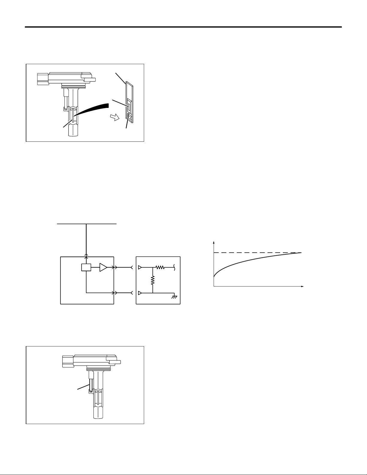
MASS AIRFLOW SENSOR
Mass airflow sensor is installed in the air intake hose. Mass airflow sensor is composed of an extremely small heatsensing
resistor. The mass airflow sensor controls the amount of elec
tric current flowing into the heat sensing resistor to keep the
heat sensing resistor at a constant temperature to the intake air
temperature. The faster the air flow speed, the higher the mass
flow rate.Because the amount of heat transfer from the heat
sensing resistor to the air increases, the mass airflow sensor
increases the amount of electric current to the heat sensing
resistor. Thus, the amount of electric current increases in
accordance with the air mass flow rate. The mass airflow sen
sor measures the air mass flow rate by detecting the amount of
electric current. The mass airflow sensor amplifies the detected
electric current amount and outputs it into the ECM. ECM uses
this output current and engine speed to calculate and decide
basic fuel injection time. Sensor properties are as shown in the
figure.
M2132001000565
-
-
From MFI relay
Mass airflow sensor ECM
Sensory part
(thermistor)
Output current mA
Mass flow g/s
AK602221AG
.
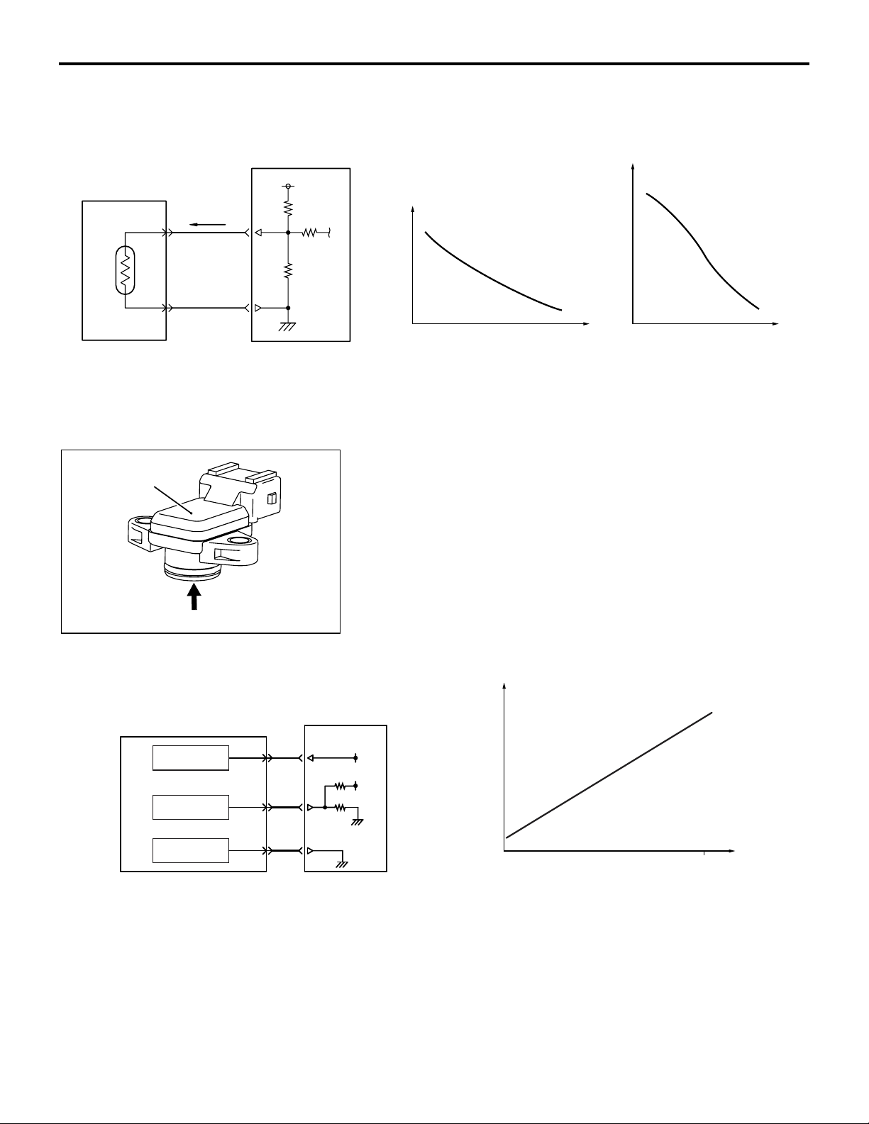
INTAKE AIR TEMPERATURE SENSOR
Intake air temperature sensor is built in to the mass airflow sensor. Intake air temperature sensor detects intake air temperature through thermistor's resistance change and outputs the
voltage according to intake air temperature to ECM. ECM uses
this output voltage to compensate fuel injection control and
ignition timing control. Sensor properties are as shown in the
figure.
AK602253AC
Page 58
MULTIPORT FUEL SYSTEM (MFI)
SENSOR
13A-9
Intake air temperature
sensor (thermistor)
Manifold absolute
pressure sensor
ECM
5V
Output voltage V
Resistance kΩ
Intake air
temperature ˚C (˚F)
.
Intake air
temperature ˚C (˚F)
AK602207
AG
MANIFOLD ABSOLUTE PRESSURE SENSOR
The manifold absolute pressure sensor is installed in the intake
manifold. Manifold absolute pressure sensor uses a piezo
resistive semiconductor to output the voltage according to man
ifold absolute pressure to ECM. ECM uses this output voltage
to compensate fuel injection volume according to manifold
absolute pressure. Sensor properties are as shown in the fig
ure.
-
-
Pressure
Manifold absolute
pressure sensor
Power supply
Output signal
Ground
AK602254AC
ECM
5V
5V
Output voltage V
0
.
101
Pressure kPa (in.Hg)
AK602206AH
Page 59
13A-10
Sensory part
(thermistor)
AK602255AC
MULTIPORT FUEL SYSTEM (MFI)
SENSOR
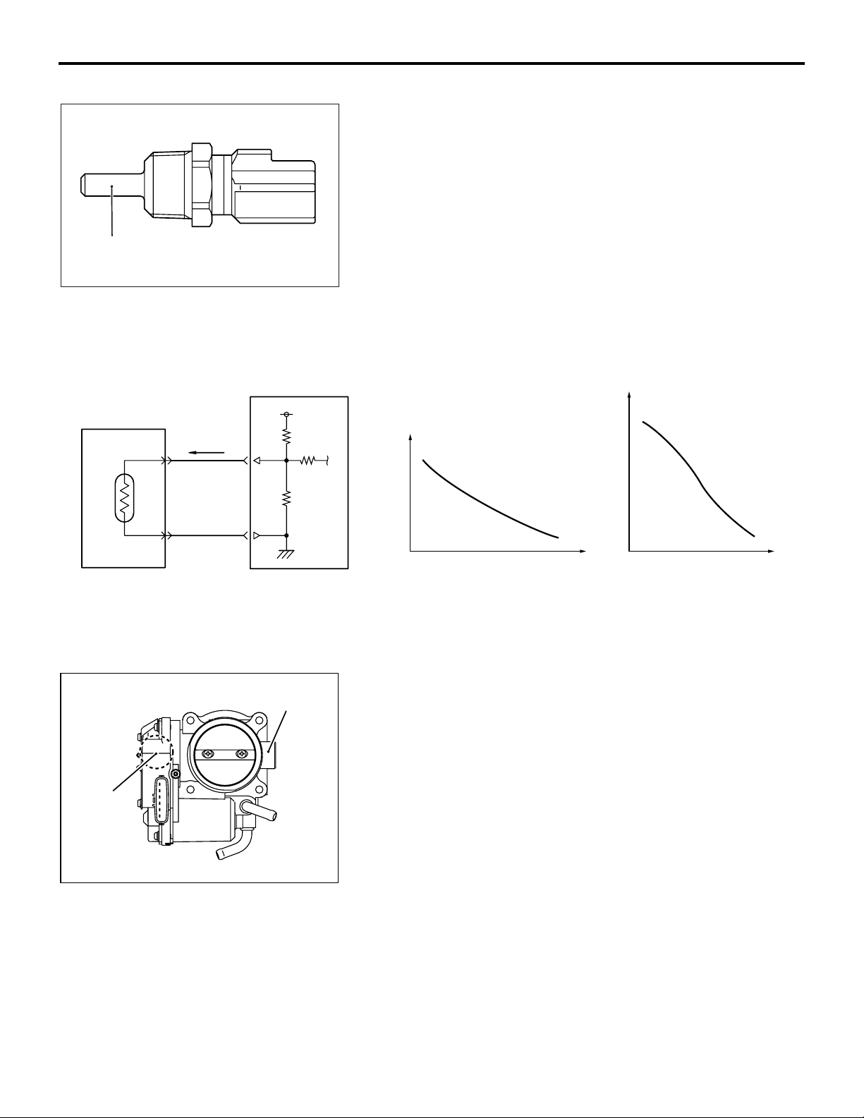
ENGINE COOLANT TEMPERATURE SENSOR
The engine coolant temperature sensor is installed in the thermostat housing. Engine coolant temperature sensor uses thermistor's resistance change to detect coolant temperature and
output the voltage according to coolant temperature to ECM.
ECM uses this output voltage to appropriately control fuel injec
tion volume, idle speed and ignition timing. Sensor properties
are as shown in the figure.
-
Engine coolant
temperature sensor
(thermistor)
ECM
5V
Throttle body
Output voltage V
Resistance kΩ
Engine coolant
temperature ˚C (˚F)
.
Engine coolant
temperature ˚C (˚F)
AK602208
AG
THROTTLE POSITION SENSOR
The throttle position sensor is installed in the throttle body.
Throttle position sensor outputs voltage to ECM based on the
throttle shaft rotation angle. ECM uses this signal to detect the
throttle valve opening angle to perform throttle actuator control
motor feedback control. This throttle position sensor uses Hall
IC and is a non-contact type.
Throttle
position
sensor
AK604120
AB
.
Page 60
Throttle shaft
Magnet
Hall IC
Stator
MULTIPORT FUEL SYSTEM (MFI)
SENSOR
STRUCTURE AND SYSTEM
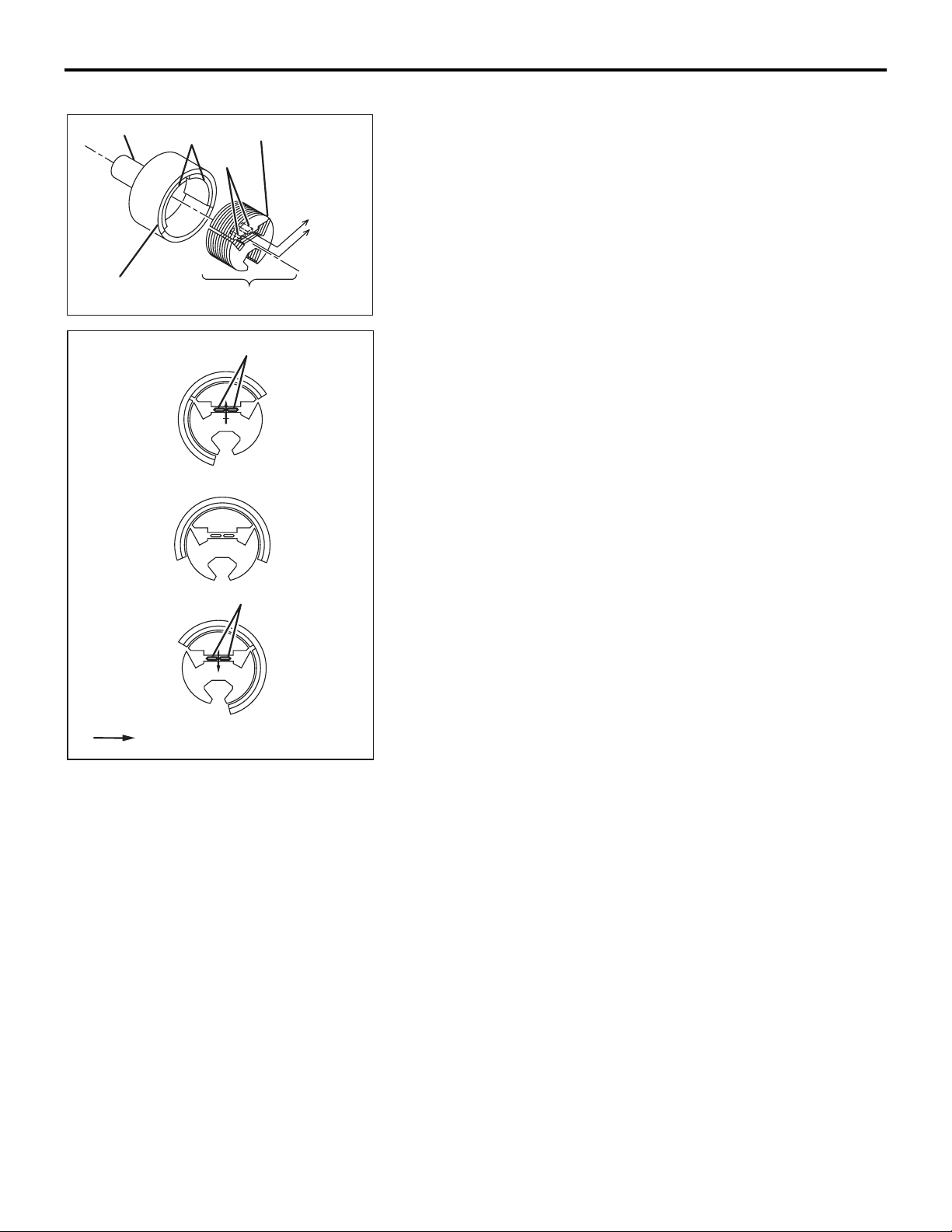
Throttle position sensor is composed of a permanent magnet
fixed on the throttle shaft, Hall IC that outputs voltage according
to magnetic flux density and a stator that efficiently introduces
magnetic flux from the permanent magnet to Hall IC.
To ECM
13A-11
Yo k e
Fully closed
Half opened
Fully opened
Magnet flux
Fixed to the motor cover
AK602566AC
Hall IC
Hall IC
AK604555
AB
Magnetic flux density at Hall IC is proportional to the output
voltage.
Throttle position sensor has 2 output systems − throttle position
sensor (main) and throttle position sensor (sub), and the output
voltage is output to ECM. When throttle valve turns, output volt
age of throttle position sensor (main) and throttle position sensor (sub) changes. This allows ECM to detect actual throttle
opening angle. ECM uses this output voltage for throttle actua
tor control motor feedback control. Also, ECM compares output
voltage of the throttle position sensor (main) and throttle posi
tion sensor (sub) to check for abnormality in the throttle position
sensor. The relationship between throttle opening angle and
output voltage of the throttle position sensor (main) and throttle
position sensor (sub) is as shown in the figure below.
-
-
Page 61
13A-12
Throttle position sensor
Throttle position
sensor (main)
Hall IC
Throttle position
sensor (sub)
5V5V
ECM
MULTIPORT FUEL SYSTEM (MFI)
SENSOR
Hall IC
Output voltage V
5
4.5
2.5
0.5
0
Fully
closed
Throttle position
sensor (main)
Throttle position
sensor (sub)
Throttle valve opening angle
Fully
opened
AK602222AE
Accelerator pedal position
sensor connector
Accelerator pedal arm
AK602569AC
.
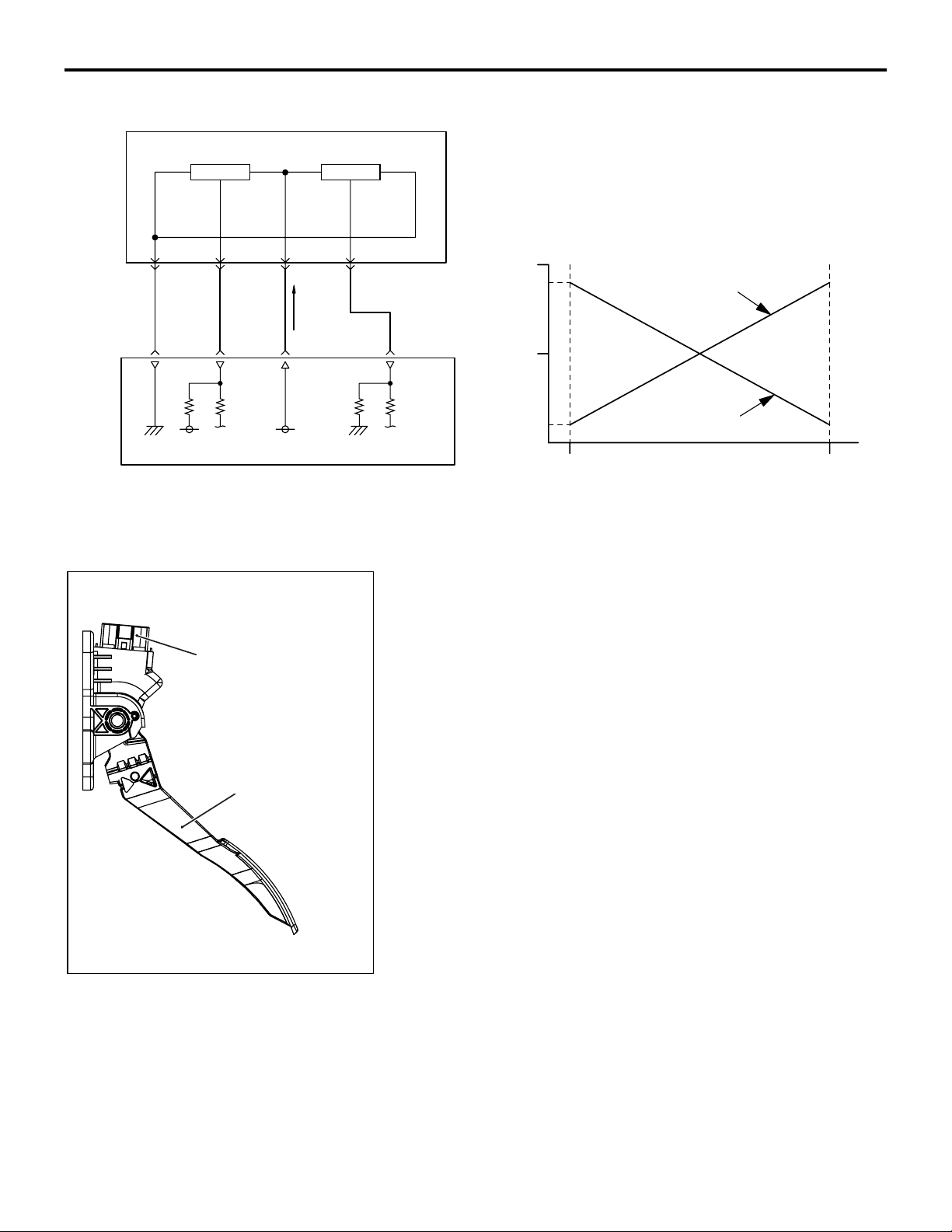
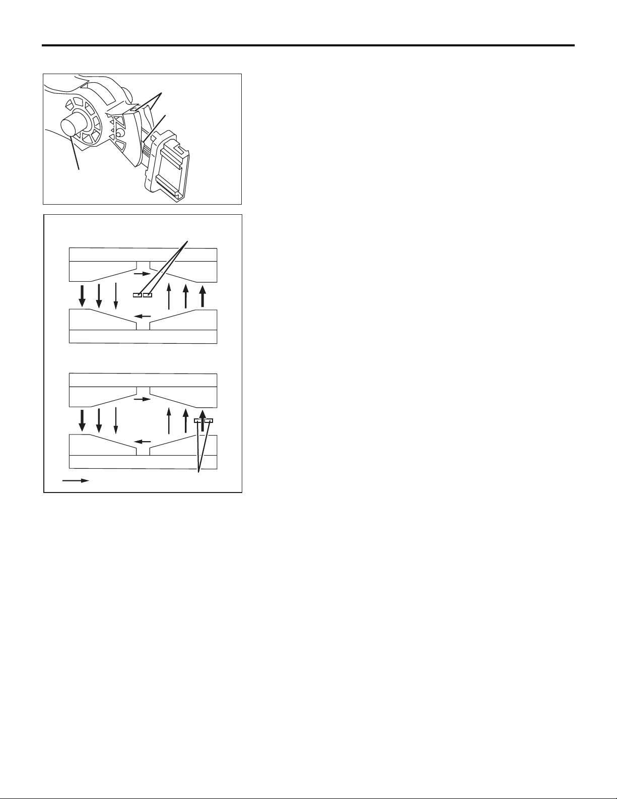
ACCELERATOR PEDAL POSITION SENSOR
Accelerator pedal position sensor is integrated with accelerator
pedal, and detects accelerator opening angle. ECM uses the
output voltage of this sensor to control appropriate throttle
valve opening angle and fuel injection volume. This accelerator
pedal position sensor uses Hall IC and is a non-contact type.
.
Page 62
Pedal shaft
Magnet
Hall IC
MULTIPORT FUEL SYSTEM (MFI)
SENSOR
STRUCTURE AND SYSTEM
Accelerator pedal position sensor is composed of a permanent
magnet fixed on the magnet carrier of the pedal shaft, Hall IC
outputs voltage according to magnetic flux density and a stator
that efficiently introduces magnetic flux from the permanent
magnet to Hall IC.
13A-13
Magnetic flux density
: minimum
Magnetic flux density
: maximum
Magnetic flux
Hall IC
N S
Hall IC
AK602570
S N
N S
S N
AK602571
AC
AC
Magnetic flux density at Hall IC is proportional to the output
voltage.
The accelerator pedal position sensor has 2 output systems −
accelerator pedal position sensor (main) and accelerator pedal
position sensor (sub), and the output voltage is output to ECM.
According to depression of the accelerator pedal, output volt
age of the accelerator pedal position sensor (main) and accelerator pedal position sensor (sub) changes. This allows ECM to
detect the actual accelerator pedal depression amount. ECM
uses accelerator pedal position sensor (main) output voltage
for appropriate throttle valve opening angle control and fuel
injection volume control. Also, ECM compares output voltage of
the accelerator pedal position sensor (main) and accelerator
pedal position sensor (sub) to check for abnormality in sensor.
The relationship between accelerator opening angle and output
voltage of the accelerator pedal position sensor (main) and
accelerator pedal position sensor (sub) is as shown in the fig
-
ure below.
Page 63
13A-14
MULTIPORT FUEL SYSTEM (MFI)
SENSOR
Accelerator pedal position sensor
Accelerator pedal
position sensor (main)
Hall IC Hall IC
Accelerator pedal
position sensor (sub)
ECM
Output voltage V
Accelerator pedal
5
position sensor (main)
4
3
2
Accelerator pedal
5V5V
1
0
Accelerator
pedal stroke
.
position sensor (sub)
Fully
opened
AK602211
AE
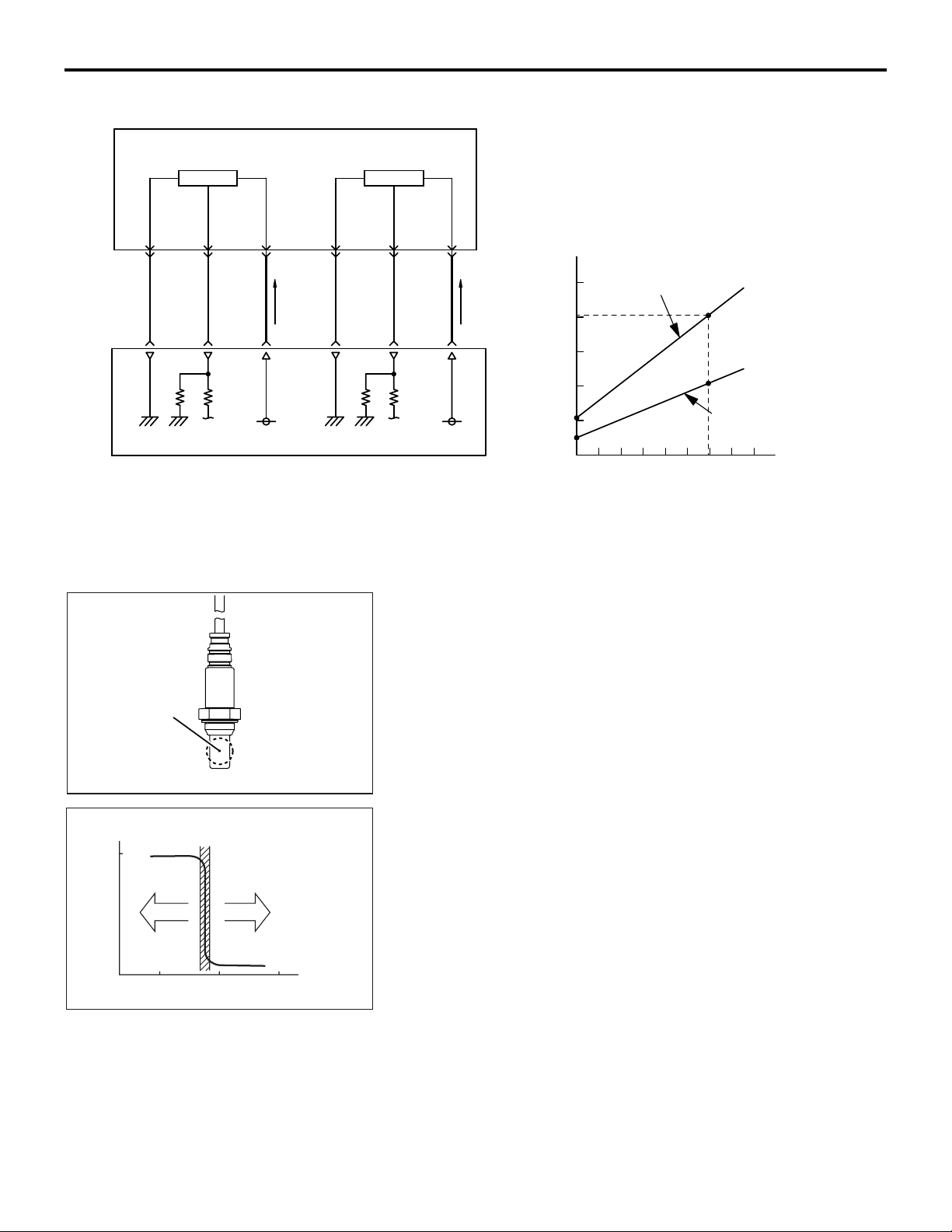
HEATED OXYGEN SENSOR (except centor
exhaust pipe heated oxygen sensor <California>)
Heated oxygen sensors are installed in 2 positions (front, rear)
on the catalytic converter. Heated oxygen sensor has a built-in
heater to help early activation of the sensor. This allows feed
back control of air-fuel ratio soon after engine start.
-
Sensing area
Electro motive
force (V)
0.8
Theoretical air fuel ratio
Rich Lean
14 15 16
Air fuel ratio
AK602572 AC
AK602262
AC
.
This sensor uses the oxygen concentration cell principle of
solid electrolyte (zirconia) and displays the property of sudden
change in output voltage near theoretical air-fuel ratio. This
property is used to detect oxygen density in exhaust gas. Feed
back to ECM allows it to judge whether air-fuel ratio is rich or
lean compared to theoretical air-fuel ratio.
-
Page 64
MULTIPORT FUEL SYSTEM (MFI)
SENSOR
13A-15
Purge ratio
100
50
0
Theoretical air fuel ratio
HC
CO
NOx
AK602263AC
Heated xygen sensor
Heater
This allows ECM precise feedback control to get theoretical
air-fuel ratio with best cleaning efficiency of 3-way catalytic con
verter.
From MFI relay
ECM
-
Zirconia element
Crankshaft sensing ring
(36 teeth including 3 missing teeth)
Crankshaft
position
sensor
AK602737AC
0.5V
AK602576AC
.
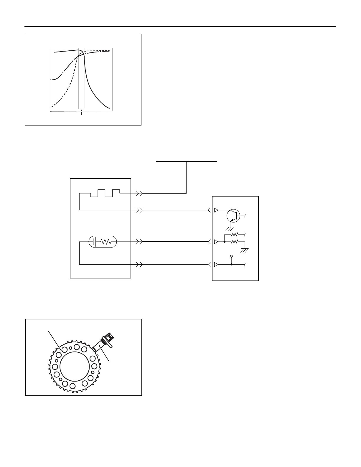
CRANKSHAFT POSITION SENSOR
A crankshaft position sensor is installed on the right side of the
cylinder block. The crankshaft position sensor monitors rotation
of crankshaft sensing ring (36 teeth including 3 missing teeth)
installed on the crankshaft and converts to voltage (pulse sig
nal) that is output to ECM. ECM uses crankshaft position sensor's output pulse to detect crankshaft position.
.
-
Page 65
13A-16
Crank shaft sensing ring
Vane
Crank shaft sensing ring
Vane
Magnet flux
Magnetic resistance element
Magnet flux
Magnetic resistance element
AK602265AC
MULTIPORT FUEL SYSTEM (MFI)
SENSOR
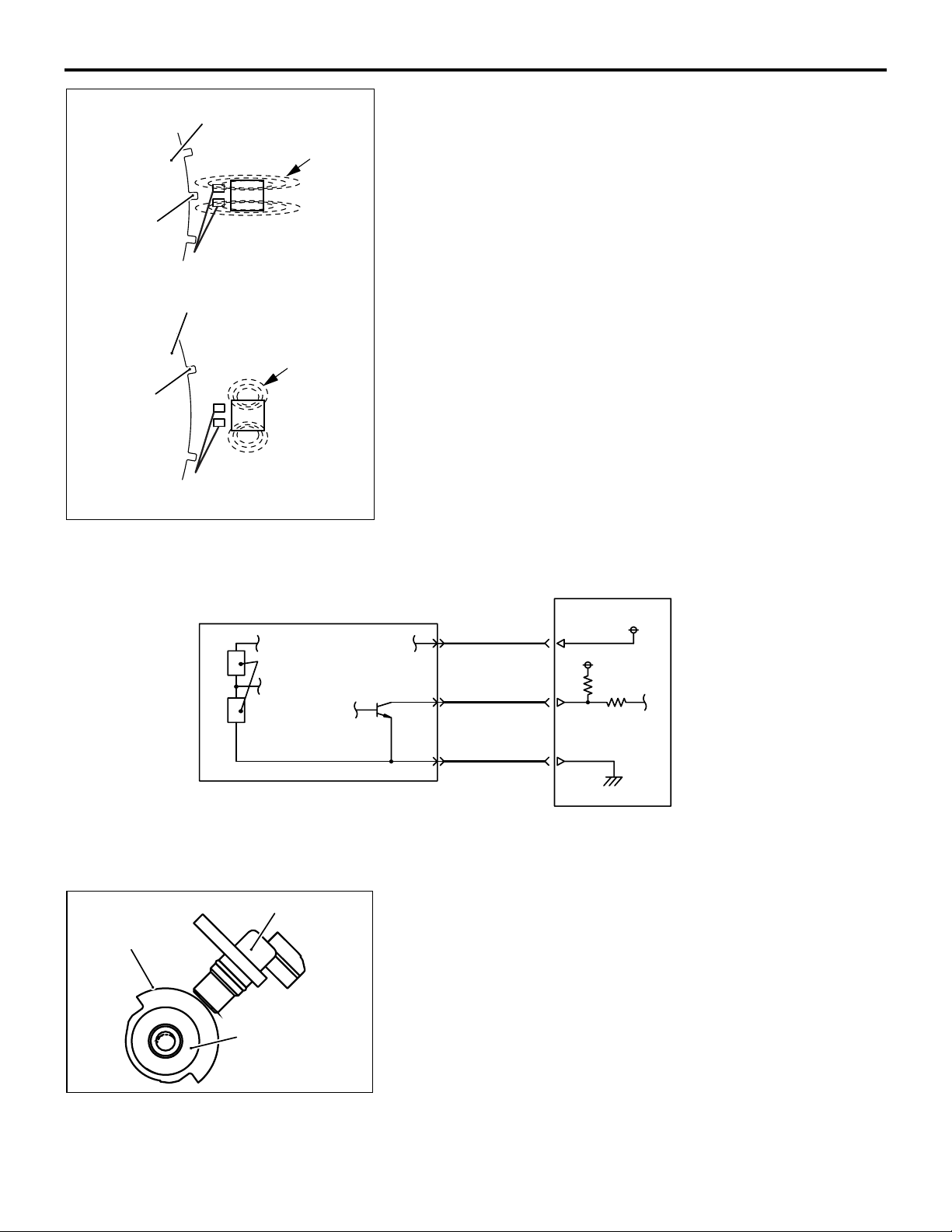
The crankshaft position sensor uses a magnetic resistance element. When the vane of the crankshaft-sensing blade passes
the front surface of the magnetic resistance element, the flux
from the magnet passes the magnetic resistance element.
Thus, resistance of the magnetic resistance element increases.
When the vane of the crankshaft-sensing blade does not pass
the front surface of the magnetic resistance element, the flux
from the magnet does not pass the magnetic resistance ele
ment and the resistance decreases. The crankshaft position
sensor converts this change in resistance of the magnetic
resistance element to a 5 V pulse signal and outputs it to ECM.
-
Sensing portion
Crankshaft position sensor
Magnetic resistance element
Camshaft position sensor
Camshaft
AK602738AC
ECM
5V
5V
Output signal
AK602285AC
.
INTAKE CAMSHAFT POSITION SENSOR
The intake camshaft position sensor is installed on the left side
of the cylinder head. The intake camshaft position sensor mon
itors shape of the half-moon sensing portion and converts to
voltage (pulse signal) that is output to ECM. Upon receiving this
output voltage, the ECM effects feedback control to optimize
the phase of the intake camshaft. Also, ECM uses a combina
tion of the intake camshaft position sensor output pulse signal
and crankshaft position sensor output pulse signal to identify
cylinders in the compression process.
-
-
Page 66
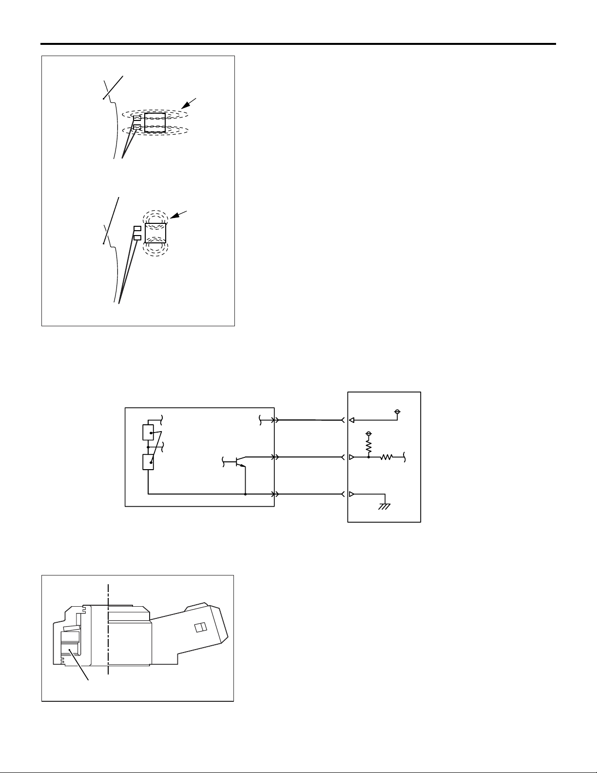
MULTIPORT FUEL SYSTEM (MFI)
SENSOR
13A-17
Camshaft position sensing portion
Magnetic resistance element
Camshaft position sensing portion
Magnet flux
Magnetic resistance element
Magnet flux
AK602574
AC
The intake camshaft position sensor uses a magnetic resistance element. When the camshaft position sensing portion
passes the front surface of the magnetic resistance element,
the flux from the magnet passes the magnetic resistance ele
ment. Thus, resistance of the magnetic resistance element
increases. When the camshaft position sensing portion does
not pass the front surface of the magnetic resistance element,
the flux from the magnet does not pass the magnetic resistance
element and the resistance decreases. The intake camshaft
position sensor converts this change in resistance of the mag
netic resistance element to a 5 V pulse signal and outputs it to
ECM
.
EXHAUST CAMSHAFT POSITION SENSOR
The exhaust camshaft position sensor is installed on the right
side of the cylinder head. The exhaust camshaft position sen
sor monitors shape of the half-moon sensing portion and converts to voltage (pulse signal) that is output to ECM. Upon
receiving this output voltage, the ECM effects feedback control
to optimize the phase of the exhaust camshaft. The structure
and system of this sensor are basically the same as intake
camshaft position sensor.
-
Camshaft position sensor
Magnetic resistance element
.
ECM
5V
5V
Output signal
AK602287
.
AC
KNOCK SENSOR
A knock sensor is installed on the left side of the cylinder block.
Knock sensor uses the piezoelectric element to convert the
vibration of the cylinder block generated when engine is in
operation to minute voltage that is output to ECM. ECM uses
the minute output voltage from the knock sensor filtered
through the cylinder block's natural frequency to detect knock
ing, and compensates the ignition timing lag according to the
strength of the knocking.
-
Piezoelectric element
AK602739
AC
Page 67
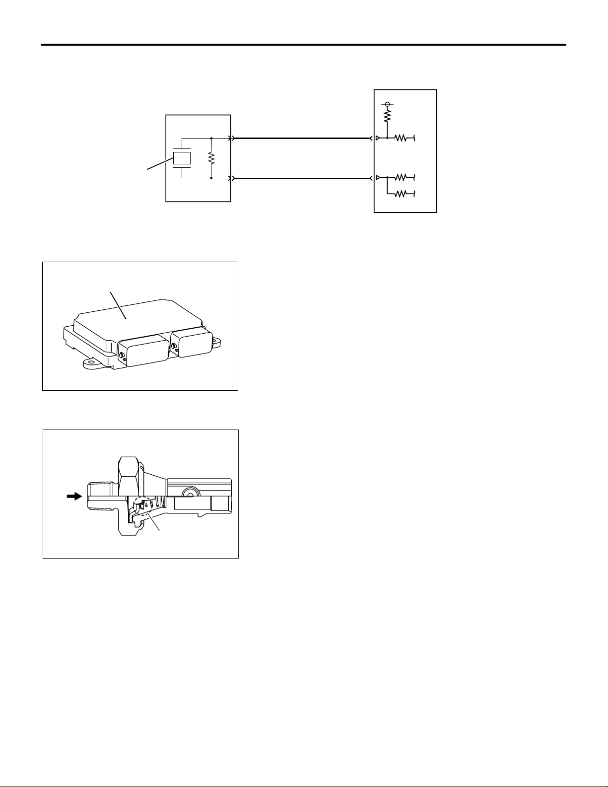
13A-18
Piezoelectric element
Barometric pressure sensor
(built in ECM)
Knock sensor
MULTIPORT FUEL SYSTEM (MFI)
SENSOR
ECM
5V
.
BAROMETRIC PRESSURE SENSOR
A barometric pressure sensor is built into ECM. The barometric
pressure sensor is a semiconductor diffused pressure element
which outputs voltage to ECM according to atmospheric pres
sure. ECM uses this output voltage to sense the altitude of the
vehicle and compensates fuel injection volume to achieve the
appropriate air-fuel ratio for that altitude.
AK602226AD
-
Oil
pressure
Contact switch
AK602575AC
AK602587AC
.
ENGINE OIL PRESSURE SWITCH
The engine oil pressure switch is installed on the left side of the
cylinder block. The engine oil pressure switch detects whether
the oil pressure is high or low using the contact switch. When
the oil pressure becomes higher than the specified value after
the engine starts, the contact point of the engine oil pressure
switch opens. This allows the ECM to detect the oil pressure is
higher than the specified value. The ECM outputs the OFF sig
nal to the combination meter through the CAN and then turns
off the oil pressure warning lamp.
-
Page 68
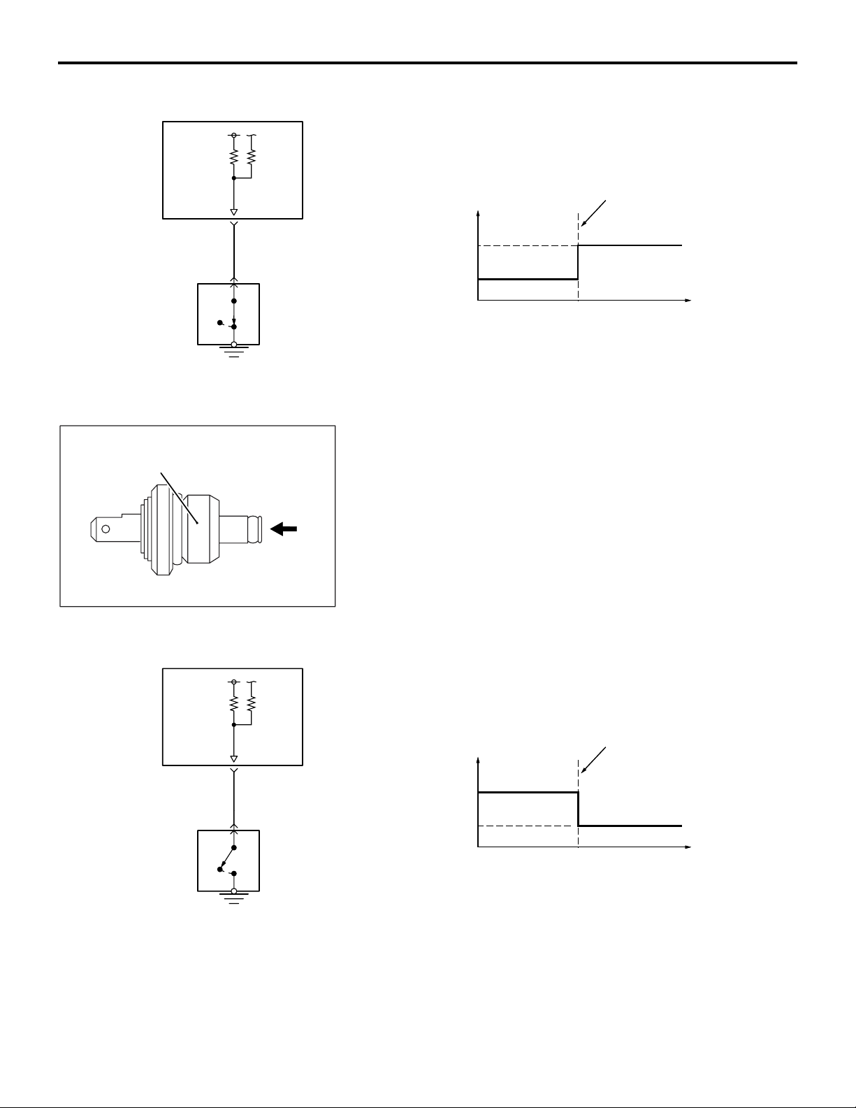
ECM
MULTIPORT FUEL SYSTEM (MFI)
SENSOR
13A-19
Power steering
pressure switch
OFF
Engine oil
ON
pressure switch
Oil
pressure
ECM terminal voltage V
12
Oil pressure:low
0
.
ON
Operating pressure
Oil pressure: high
OFF
Oil pressure kPa (in.Hg)
AK602228
AD
POWER STEERING PRESSURE SWITCH
A power steering pressure switch is installed on the power
steering oil pump. The power steering pressure switch uses a
contact switch to detect the power steering oil pressure. When
power steering oil pressure rises due to operation of the steer
ing wheel, the power steering load switch outputs an ON signal
to ECM. ECM performs idle-up according to the voltage and
prevents reduction in engine speed due to power steering load
and so maintains stable idle speed.
-
OFF
ECM
AK601174AF
Power steering
pressure switch
ON
ECM
terminal voltage V
Oil pressure:low
12
0
.
OFF
Operating pressure
Oil pressure: high
ON
Oil pressure kPa (in.Hg)
AK602213
AE
Page 69
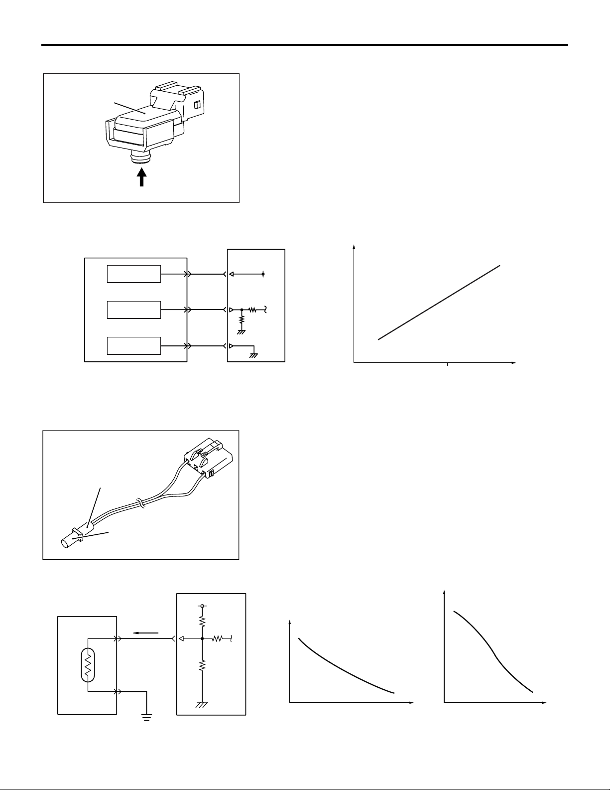
13A-20
Fuel tank differential
pressure sensor
Pressure
AK604121
MULTIPORT FUEL SYSTEM (MFI)
SENSOR
FUEL TANK DIFFERENTIAL PRESSURE SENSOR
The fuel tank differential pressure sensor is installed to the fuel
pump module. The fuel tank differential pressure sensor out
puts the voltage to the ECM using the piezo resistive semiconductor in accordance with the difference between pressure in
the fuel tank and the pressure of the atmosphere. When moni
toring the evaporative leak, the ECM detects malfunctions of
the evaporative emission control system by monitoring the
amount of output voltage changes from this sensor. The sensor
characteristics are as shown in the diagram.
AB
-
-
Fuel tank differential pressure sensor
Power supply
Output signal
Ground
Fuel tank
temperature
sensor
Sensory part
(thermistor)
ECM
5 V
.
Output voltage V
0
Pressure kPa (in. Hg)
AK604122
FUEL TANK TEMPERATURE SENSOR
The fuel tank temperature sensor is installed to the fuel pump
module. The fuel tank temperature sensor detects the tempera
ture inside the fuel tank using the resistance change in the thermistor and outputs the voltage to the ECM in accordance with
the temperature inside the fuel tank. The ECM monitors the
evaporative leak in accordance with the fuel tank temperature.
The sensor characteristics are as shown in the diagram.
AB
-
Fuel tank temperature
sensor (thermistor)
AK604123 AB
ECM
5 V
Resistance kΩ
Output voltage V
Fuel tank
temperature ˚C (˚F)
Fuel tank
temperature ˚C (˚F)
AK604124
AB
Page 70
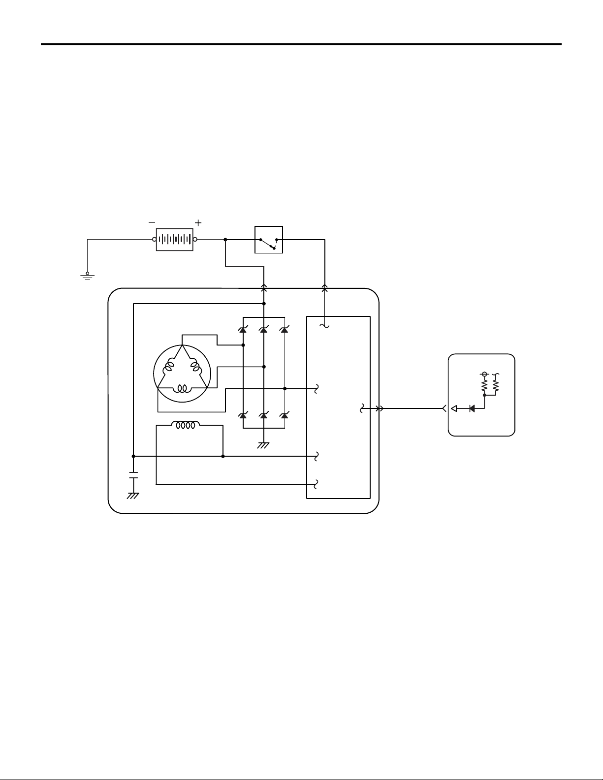
Battery
MULTIPORT FUEL SYSTEM (MFI)
SENSOR
.
GENERATOR FR TERMINAL
Generator turns ON/OFF the power transistor in the voltage
regulator to adjust current flow in the field coil according to
alternator output current. In this way generator's output voltage
is kept adjusted (to about 14.7 V). The ratio of power transistor
ON time (ON duty) is output from generator FR terminal to
ECM. ECM uses this signal to detect generator's output current
and drives throttle actuator control motor according to output
current (electric load). This prevents change in idle speed due
to electric load and helps maintain stable idle speed.
Ignition switch-IG
BS
13A-21
Field coil
ECM
FR
IC regulator
Generator
AK602229AD
.
Page 71
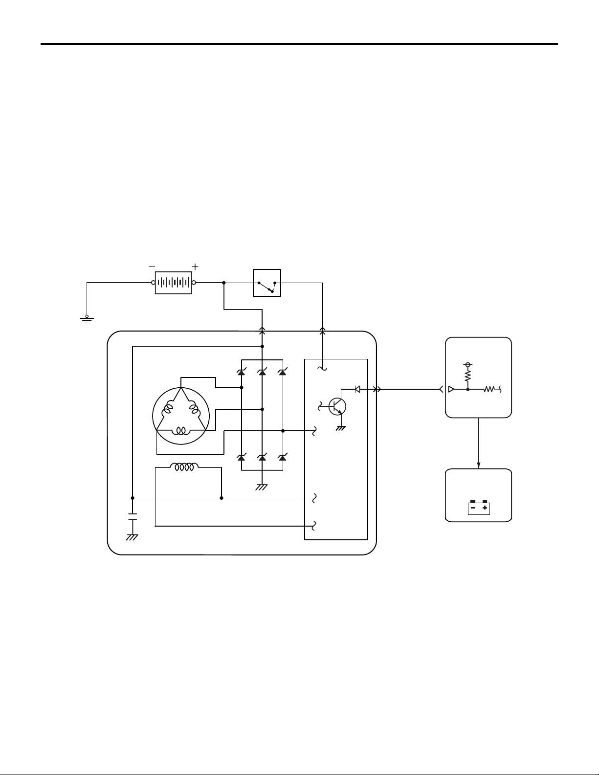
13A-22
Battery
MULTIPORT FUEL SYSTEM (MFI)
SENSOR
GENERATOR L TERMINAL
After turning on the ignition switch, the current is input by the
ECM to the generator L terminal. This allows the IC regulator to
be on and the field coil to be excited. When the generator
rotates in this situation, the voltage is excited in the stator coil
and the current is output from B-terminal through the commuta
tion diode. Also the generated voltage is input to the voltage
regulator through the commutation diode. After the electric gen
eration begins, the current is supplied to the field coil from this
circuit. In addition, the generated voltage is output from the
generator L terminal to the ECM. This allows the ECM to detect
that the electric generation begins. The ECM outputs the ON
signal to the combination meter through the CAN and then
turns off the generator malfunction light.
Ignition switch-IG
-
-
Field coil
BS
Generator
IC regulator
ECM
L
CAN
communication
Generator
malfunction
light
Combination meter
AK602577
AC
Page 72
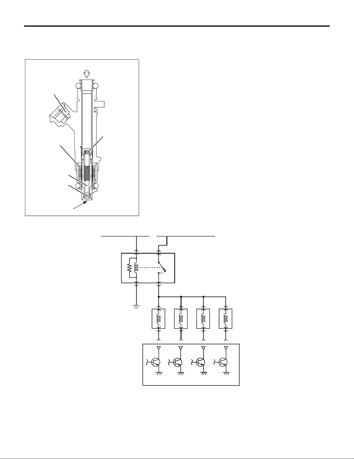
MULTIPORT FUEL SYSTEM (MFI)
ACTUATOR
13A-23
Connector
Solenoid coil
Plunger
Ball valve
Fuel
ACTUATOR
M2132002000353
INJECTOR
An injector is an injection nozzle with the electromagnetic valve
that injects fuel based on the injection signal sent by ECM. 1
injector is installed in the intake manifold of each cylinder and
fixed to the fuel rail. When electricity flows through the solenoid
coil, the plunger gets sucked in. The ball valve is integrated
with the plunger, and gets pulled together with the plunger till
the fully open position so that the injection hole is fully open
and the fuel gets injected.
Filter
Plate
AK602272AC
From ETACS-ECU
From MFI relay
ON
No. 1 No. 2 No. 3 No. 4
Injector relay
OFF
Injectors
ECM
AK602578
AC
Voltage from the battery gets applied from the injector relay to
the injector and up to the ECM. ECM turns ON its power tran
sistor and prepares the injector's ground circuit. Thus, current
flows through the injector while power transistor is ON and the
injector injects fuel.
Page 73
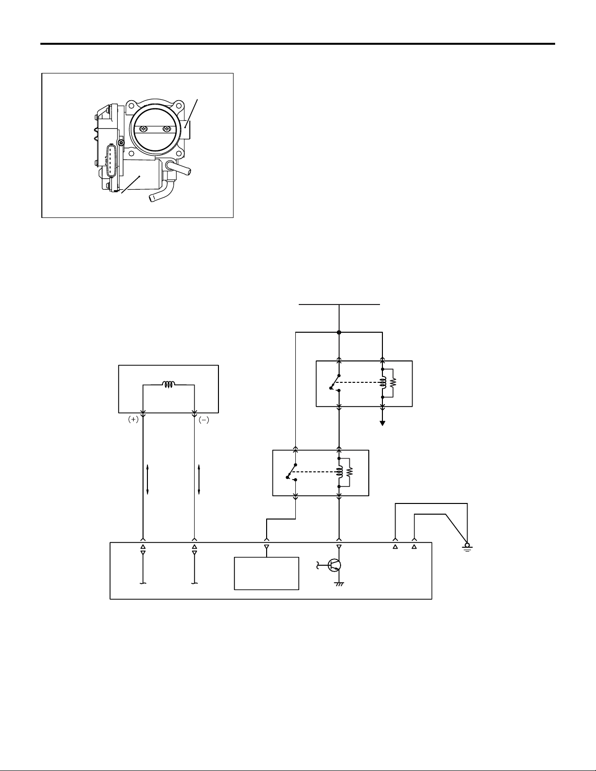
13A-24
Throttle actuator
control motor
Throttle body
AK604125
MULTIPORT FUEL SYSTEM (MFI)
ACTUATOR
THROTTLE ACTUATOR CONTROL MOTOR
A throttle actuator control motor is installed in throttle body. The
throttle actuator control motor performs the Open/Close of the
throttle valve through the reduction gear. ECM changes current
direction according to the Open/Close direction and also
changes current to the motor coil to control the throttle actuator
control motor.
Throttle actuator control motor is composed of a good
response, low energy, and small DC motor with brush and can
generate rotation force corresponding to the current applied on
the coil. When there is no current passing through the throttle
AB
actuator control motor, the throttle valve remains at a pre
scribed opening angle. So, even if current stops because of a
fault in the system, a minimum level of running remains possi
ble.
From battery
-
-
Throttle actuator
control motor
OFF
Power supply
ON
OFF
ON
MFI relay
To ECM
Throttle actuator
control motor relay
ECM
AK602231
AE
Page 74
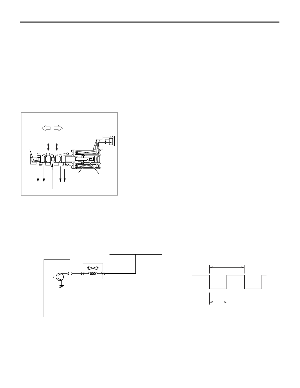
Spool valve movement
Advance
chamber
Spring
Drain
Oil pressure
Retard
chamber
Drain
Coil
MULTIPORT FUEL SYSTEM (MFI)
ACTUATOR
IGNITION COIL
Refer to GROUP 16 − Ignition Coil P.16-2.
EXHAUST GAS RECIRCULATION (EGR) VALVE
Refer to GROUP 17 − Emission Control − Exhaust Gas Recircu-
lation (EGR) System P.17-12.
EVAPORATIVE EMISSION PURGE SOLENOID
Refer to GROUP 17 − Emission Control − Evaporative Emission
Control System
INTAKE ENGINE OIL CONTROL VALVE
The intake engine oil control valve is installed on the left side of
the cylinder head. Receiving the duty signal from the ECM, the
intake engine oil control valve moves the spool valve position
and divides the oil pressure from the cylinder block into the
advanced chamber and the retarded chamber of the V.V.T.
sprocket as well as continually changes the intake camshaft
phase. The spring makes spool valve stop at the position
where the intake camshaft is at the most retarded angle when
the engine is stopped. The ECM moves the spool valve posi
tion by increasing and decreasing ON duty ratio of the intake
Plunger
AK604740
AD
engine oil control valve and allows the intake camshaft to be at
the target phase angle. When the duty ratio increases, the
spool valve moves. The sprocket rotates toward the advanced
angle side. When the duty ratio decreases, the sprocket rotates
toward the retarded angle side. When the medium duty ratio, at
which the spool valve is at the medium position, is achieved, all
the oil passages are closed. This allows the phase angle to be
kept constant. The ECM changes and controls the duty ratio in
accordance with the engine operation to get the optimum
phase angle.
13A-25
P.17-11.
-
ECM
Intake engine oil
control valve
From MFI relay
12V
0V
50ms
OFF
ON
T
The longer the ON position, the more
advanced the intake camshaft angle
AK602579
AD
Page 75
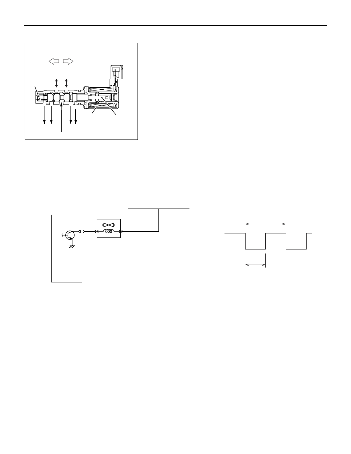
13A-26
Spool valve movement
Retard
chamber
Spring
Drain
Oil pressure
Advance
chamber
Drain
Coil
Plunger
AK604747
MULTIPORT FUEL SYSTEM (MFI)
ACTUATOR
EXHAUST ENGINE OIL CONTROL VALVE
The exhaust engine oil control valve is installed on the right
side of the cylinder head. Receiving the duty signal from the
ECM, the exhaust engine oil control valve moves the spool
valve position and divides the oil pressure from the cylinder
block into the advanced chamber and the retarded chamber of
the V.V.T. sprocket as well as continually changes the exhaust
camshaft phase. The spring makes spool valve stop at the
position where the exhaust camshaft is at the most advanced
angle when the engine is stopped. The ECM moves the spool
valve position by increasing and decreasing ON duty ratio of
the exhaust engine oil control valve and allows the exhaust
camshaft to be at the target phase angle. When the duty ratio
AC
increases, the spool valve moves. The sprocket rotates toward
the retarded angle side. When the duty ratio decreases, the
sprocket rotates toward the advanced angle side. When the
medium duty ratio, at which the spool valve is at the medium
position, is achieved, all the oil passages are closed. This
allows the phase angle to be kept constant. The ECM changes
and controls the duty ratio in accordance with the engine oper
ation to get the optimum phase angle.
-
ECM
Exhaust engine oil
control valve
From MFI relay
12V
0V
50ms
OFF
ON
T
The longer the ON position, the more
retarded the exhaust camshaft angle
AK602579
AG
Page 76
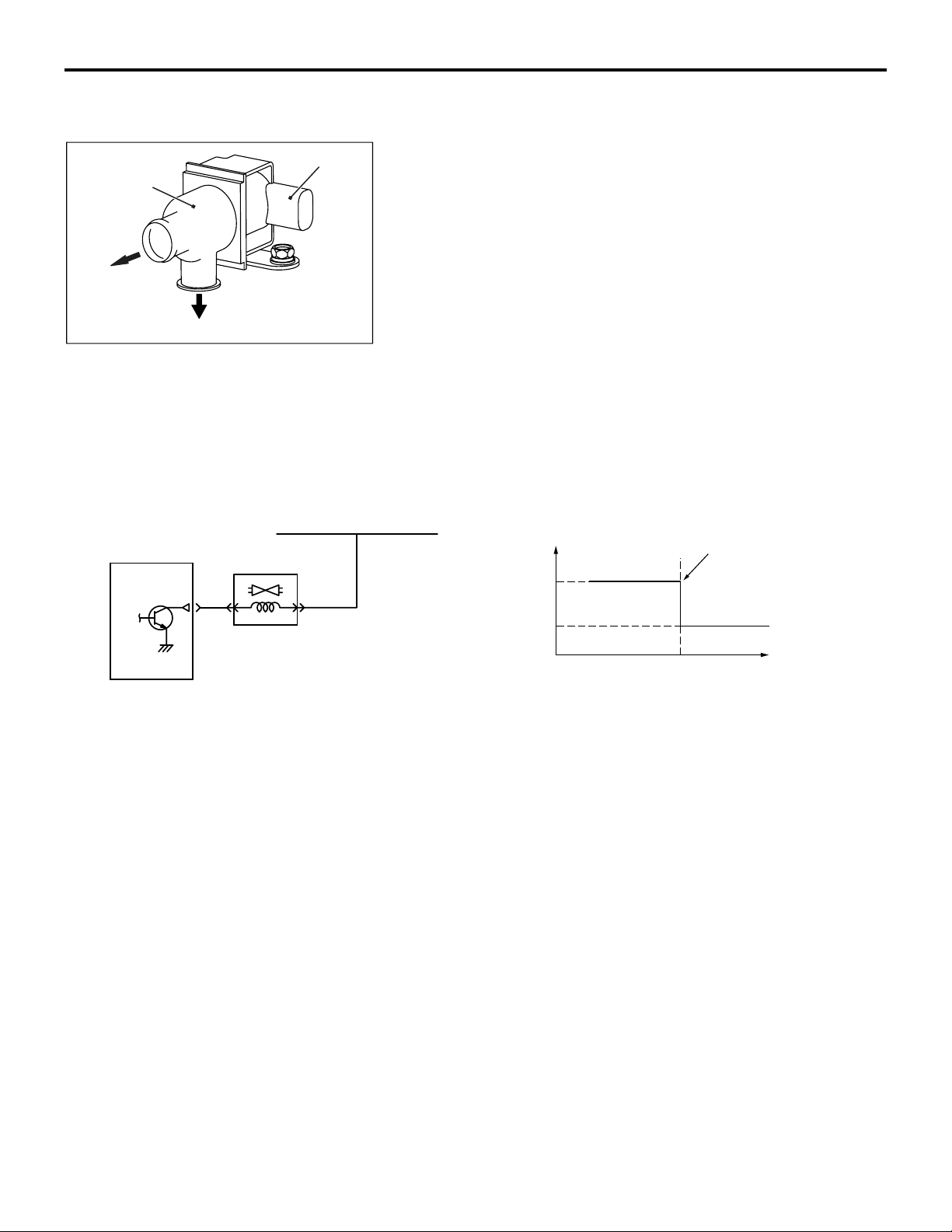
Evaporative
emission
ventilation
solenoid
To filter
To canister
MULTIPORT FUEL SYSTEM (MFI)
Connector
AK604127AB
ACTUATOR
13A-27
EVAPORATIVE EMISSION VENTILATION
SOLENOID
The evaporative emission ventilation solenoid, an ON/OFF
type solenoid valve, is integrated in the evaporative canis
ter.The evaporative emission ventilation solenoid is installed
between the evaporative canister and the air-releasing end,
where the evaporative emission ventilation solenoid takes or
shuts off air.When the current is not flowing through the coil, the
air flows between the nipples, "A" and "B", and through the
evaporative canister.When the current is flowing through the
coil, the air is sealed in the nipple "A" and the air through the
evaporative canister is shut off.When monitoring the evapora
tive leak, the ECM turns the evaporative emission ventilation
solenoid on to create the slight vacuum condition in the evapo
rative emission control system. The ECM shuts off the air flowing through the evaporative canister to maintain the vacuum
condition necessary for monitoring.
-
-
-
ECM
From MFI relay
Evaporative emission
ventilation solenoid
ECM terminal voltage V
12
0
OFF
Engine speed to switch
evaporative emission
ventilation solenoid
ON
Engine speed r/min
AK604554
AB
Page 77
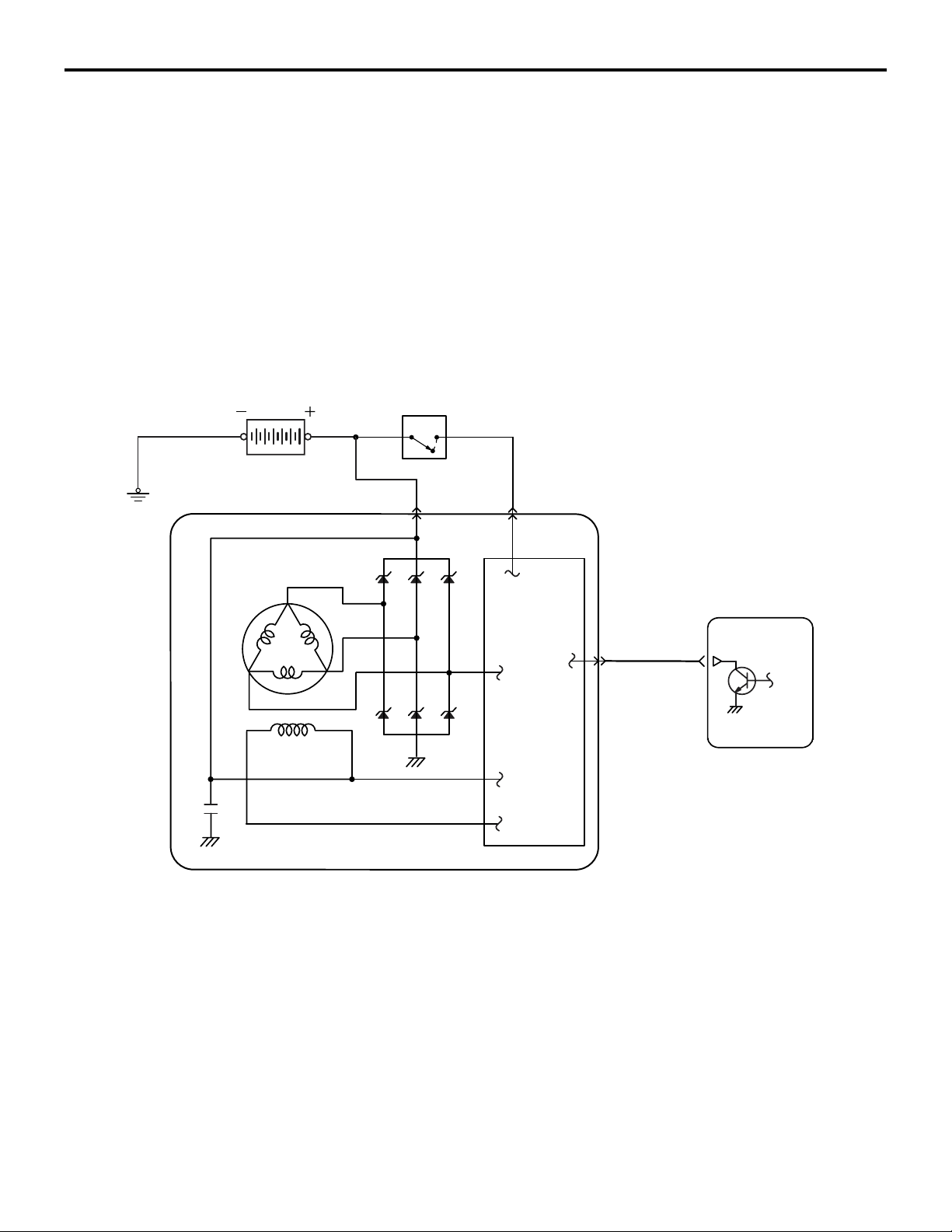
13A-28
Battery
MULTIPORT FUEL SYSTEM (MFI)
ACTUATOR
GENERATOR G TERMINAL
ECM uses ON/OFF of generator G terminal to control generator output voltage. When the power transistor in the ECM turns
ON, output voltage gets adjusted to about 12.8 V. When gener
ator output voltage drops to 12.8 V it becomes lower than voltage of the charged battery and almost no current is output from
the generator. When the power transistor in the ECM turns
OFF, output voltage gets adjusted to about 14.7 V. When gen
erator output voltage is about 14.7 V, generator outputs current
to produce electricity. In case electric load is generated sud
denly, ECM controls generator G terminal's On-duty to limit the
sudden increase in generator load due to generation and thus
prevents change in idle speed.
Ignition switch-IG
-
-
-
Field coil
BS
ECM
G
IC regulator
Generator
AK602233AD
Page 78
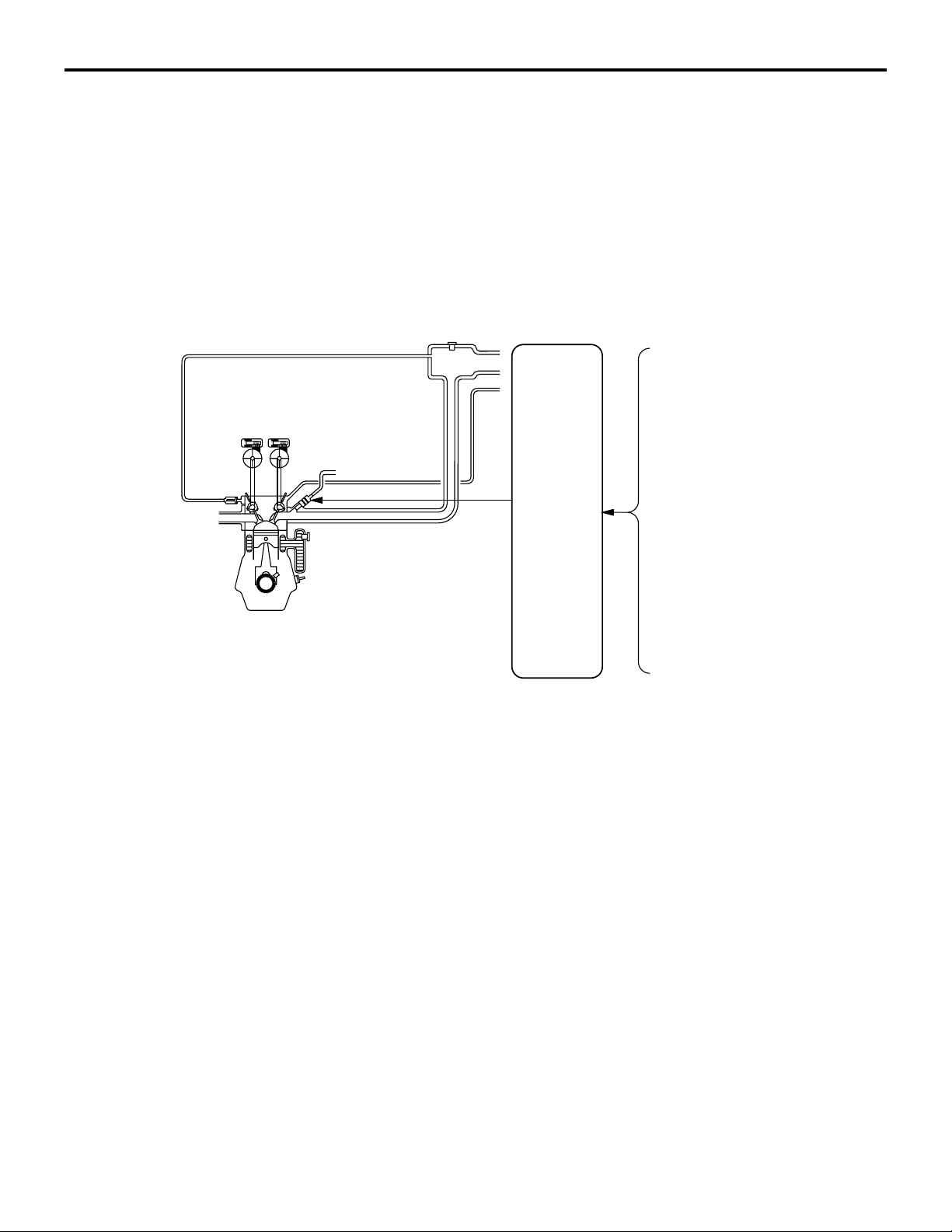
MULTIPORT FUEL SYSTEM (MFI)
FUEL INJECTION CONTROL
13A-29
FUEL INJECTION CONTROL
Fuel injection volume is regulated to obtain the optimum air-fuel ratio in accordance with the constant
minute changes in engine driving conditions. Fuel
injection volume is controlled by injector drive time
(injection time). There is a prescribed basic drive
time that varies according to the engine speed and
System Configuration Diagram
Injector
M2132003001036
intake air volume. ECM adds prescribed compensa
tions to this basic drive time according to conditions
such as the intake air temperature and engine cool
ant temperature to decide injection time. Fuel injection is done separately for each cylinder and is done
once in two engine rotations.
Mass airflow sensor
Intake air temperature sensor
Manifold absolute
pressure sensor
Engine coolant
temperature sensor
ECM
Accelerator pedal position sensor
Knock sensor
Intake camshaft position sensor
Crankshaft position sensor
Ignition switch-ST
Heated oxygen sensor (front, rear)
AK604128
1. INJECTOR ACTUATION (FUEL INJECTION)
TIMING
Injector drive time in case of multiport fuel injection (MFI) is
controlled as follows according to driving conditions.
AB
Page 79
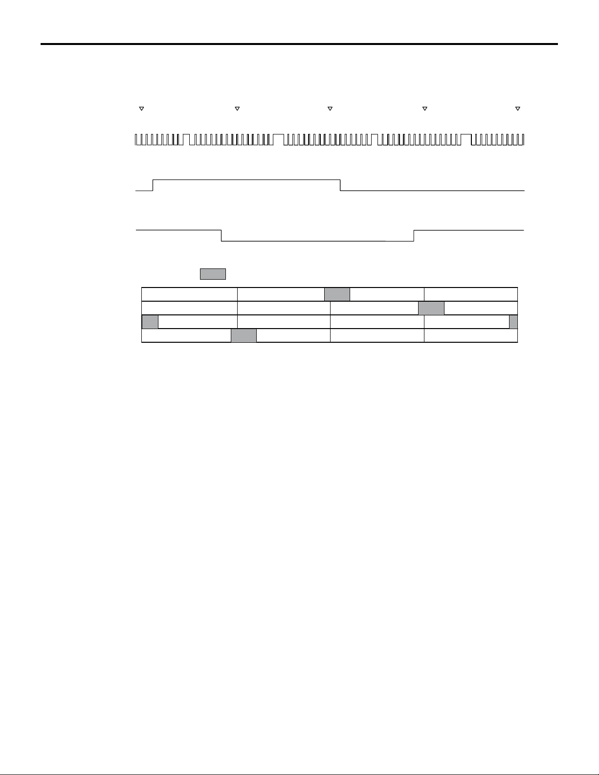
13A-30
MULTIPORT FUEL SYSTEM (MFI)
FUEL INJECTION CONTROL
Fuel Injection During Cranking and Normal Operation
Crankshaft
position
sensor signal
Intake camshaft
position sensor
signal
Exhaust camshaft
position sensor
signal
Cylinder stroke
No. 1 Cylinder
No. 3 Cylinder
No. 4 Cylinder
No. 2 Cylinder
<No. 2 TDC>
H
L
H
L
H
L
Compression
Intake
Exhaust
Combustion
<No.1 TDC> <No. 3 TDC> <No. 4 TDC> <No. 2 TDC>
: Fuel injection
Combustion
Compression Combustion
Intake
Exhaust
Exhaust
Compression
Intake
Intake
Exhaust
Combustion
Compression
AK604622AB
Fuel injection to each cylinder is done by driving the injector at
optimum timing while it is in exhaust process based on the
crankshaft position sensor signal. ECM compares the crank
shaft position sensor output pulse signal and intake camshaft
position sensor output pulse signal to identify the cylinder.
Using this as a base, it performs sequential injection in the
sequence of cylinders 1, 3, 4, 2.
Page 80
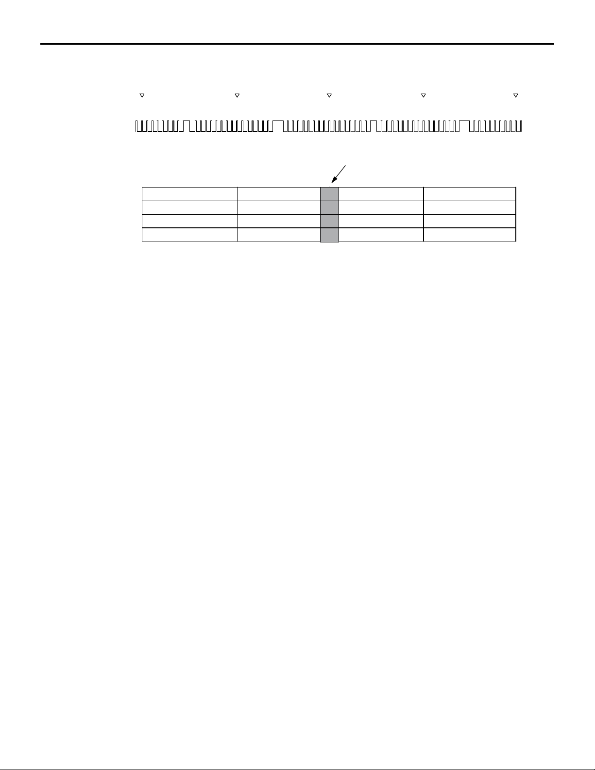
MULTIPORT FUEL SYSTEM (MFI)
FUEL INJECTION CONTROL
Additional Fuel Injection During Acceleration
<No. 2 TDC> <No.1 TDC> <No. 3 TDC> <No. 4 TDC> <No. 2 TDC>
13A-31
Crankshaft
position sensor
signal
Cylinder stroke
No. 1 Cylinder
No. 3 Cylinder
No. 4 Cylinder
No. 2 Cylinder
H
L
Increase injection for acceleration
Compression
Intake
Exhaust
Combustion
Combustion
Compression Combustion
Intake
Exhaust
Exhaust
Compression
Intake
Intake
Exhaust
Combustion
Compression
AK604623
AB
In addition to the synchronizing fuel injection with crankshaft
position sensor signal during acceleration, the volume of fuel is
injected according to the extent of the acceleration.
2. Fuel injection volume (injector drive time)
control
The figure shows the flow for injector drive time calculation.
Basic drive time is decided based on the mass airflow sensor
signal (intake air volume signal) and crankshaft position sensor
signal (engine rotation signal). This basic drive time is compen
sated according to signals from various sensors and optimum
injector drive time (fuel injection volume) is calculated accord
ing to driving conditions.
-
-
Page 81
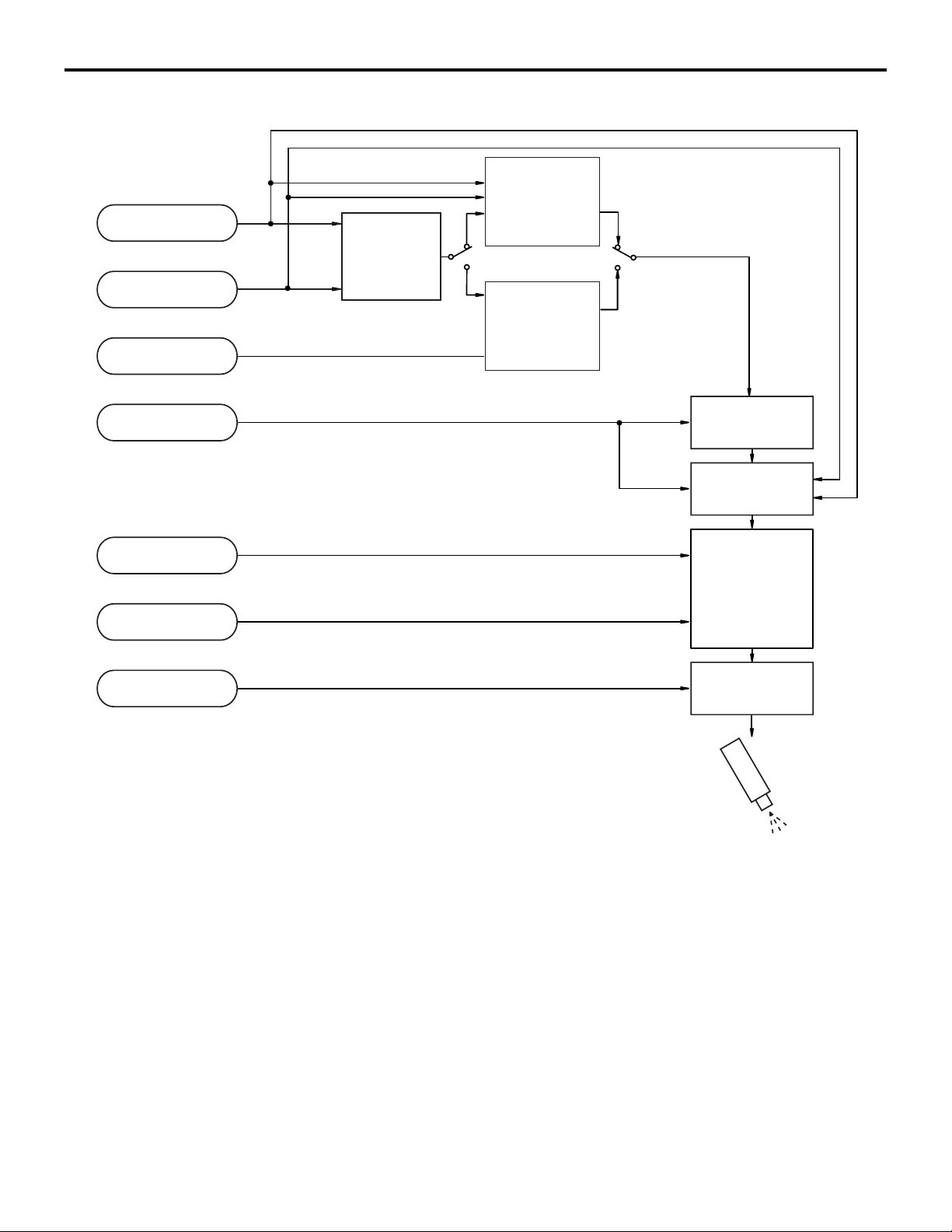
13A-32
MULTIPORT FUEL SYSTEM (MFI)
FUEL INJECTION CONTROL
Fuel Injection Volume Control Block Diagram
Mass airflow sensor
Basic fuel
injection time
Crankshaft
position sensor
Heated oxygen
sensor
determination
Air fuel ratio
compensation
(Predetermined
compensation)
Heated oxygen
sensor feedback
compensation
Engine coolant
temperature sensor
Barometric pressure
sensor
Manifold absolute
pressure sensor
Battery voltage
Engine coolant
temperature
compensation
Accelerationdeceleration
compensation
Fuel pressure
compensation
Battery voltage
compensation
Injector
AK602278AD
.
Page 82

MULTIPORT FUEL SYSTEM (MFI)
FUEL INJECTION CONTROL
[Injector basic drive time]
Fuel injection is performed once per cycle for each cylinder.
Basic drive time refers to fuel injection volume (injector drive
time) to achieve theoretical air-fuel ratio for the intake air vol
ume of 1 cycle of 1 cylinder. Fuel injection volume changes
according to the pressure difference (injected fuel pressure)
between manifold absolute pressure and fuel pressure (con
stant). So, injected fuel pressure compensation is made to
injector drive time for theoretical air-fuel ratio to arrive at basic
drive time.
13A-33
-
-
Basic fuel
injection time
Intake air amount per cycle per cylinder
Fuel injection pressure compensation
Theoretical air-fuel ratio
AK602279AC
Intake air volume of each cycle of 1 cylinder is calculated by
ECM based on the mass airflow sensor signal and crankshaft
position sensor signal. Also, during engine start, the map value
prescribed by the engine coolant temperature sensor signal is
used as basic drive time.
.
Page 83

13A-34
MULTIPORT FUEL SYSTEM (MFI)
FUEL INJECTION CONTROL
[Injector drive time compensation]
After calculating the injector basic drive time, the ECM makes
the following compensations to control the optimum fuel injec
tion volume according to driving conditions.
List of main compensations for fuel injection control
Compensations Content
Heated oxygen sensor feedback compensation The heated oxygen sensor signal is used for
making the compensation to get air-fuel ratio with
best cleaning efficiency of the 3-way catalytic
converter. This compensation might not be made
sometimes in order to improve drivability,
depending on driving conditions. (Air-fuel ratio
compensation is made.)
Air-fuel ratio compensation Under driving conditions where heated oxygen
sensor feedback compensation is not performed,
compensation is made based on pre-set map
values that vary according to engine speed and
intake air volume.
Engine coolant temperature compensation Compensation is made according to the engine
coolant temperature. The lower the engine coolant
temperature, the greater the fuel injection volume.
-
Acceleration/ Deceleration compensation Compensation is made according to change in
intake air volume. During acceleration, fuel injection
volume is increased. Also, during deceleration, fuel
injection volume is decreased.
Fuel injection compensation Compensation is made according to the pressure
difference between atmospheric pressure and
manifold absolute pressure. The greater the
difference in pressure, the shorter the injector drive
time.
Battery voltage compensation Compensation is made depending on battery
voltage. The lower the battery voltage, the greater
the injector drive signal time.
Learning value for fuel compensation Compensation amount is learned to compensate
feedback of heated oxygen sensor. This allows
system to compensate in accordance with engine
characteristics.
.
[Fuel limit control during deceleration]
ECM limits fuel when decelerating downhill to prevent excessive rise of catalytic converter temperature and to improve fuel
efficiency.
.
[Fuel-cut control when over-run]
When engine speed exceeds a prescribed limit (6,600 r/min),
ECM cuts fuel supply to prevent overrunning and thus protect
the engine. Also, if engine speed exceeds 4,000 r/min for 15
seconds while vehicle is stationary (no load), it cuts fuel supply
and controls the throttle valve opening angle to protect the
engine.
Page 84
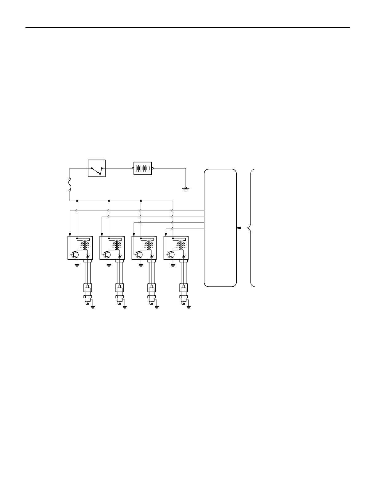
MULTIPORT FUEL SYSTEM (MFI)
IGNITION TIMING AND CONTROL FOR CURRENT CARRYING TIME
IGNITION TIMING AND CONTROL FOR CURRENT
13A-35
CARRYING TIME
Ignition timing is pre-set according to engine driving
conditions. Compensations are made according to
pre-set values depending on conditions such as
engine coolant temperature, battery voltage etc. to
decide optimum ignition timing. Primary current con
nect/disconnect signal is sent to the power transistor
to control ignition timing. Ignition is done in sequence
of cylinders 1, 3, 4, 2.
System Configuration Diagram
MFI relay
Battery
M2132027100089
-
Mass airflow sensor
Intake air temperature sensor
Manifold absolute
pressure sensor
Engine coolant
temperature sensor
ECM
Intake camshaft position sensor
Ignition
coils
Spark plugs
Cylinder No. 1 2 3 4
Exhaust camshaft position sensor
Crankshaft position sensor
Throttle position sensor
Knock sensor
Ignition switch-ST
AK502722AD
Page 85
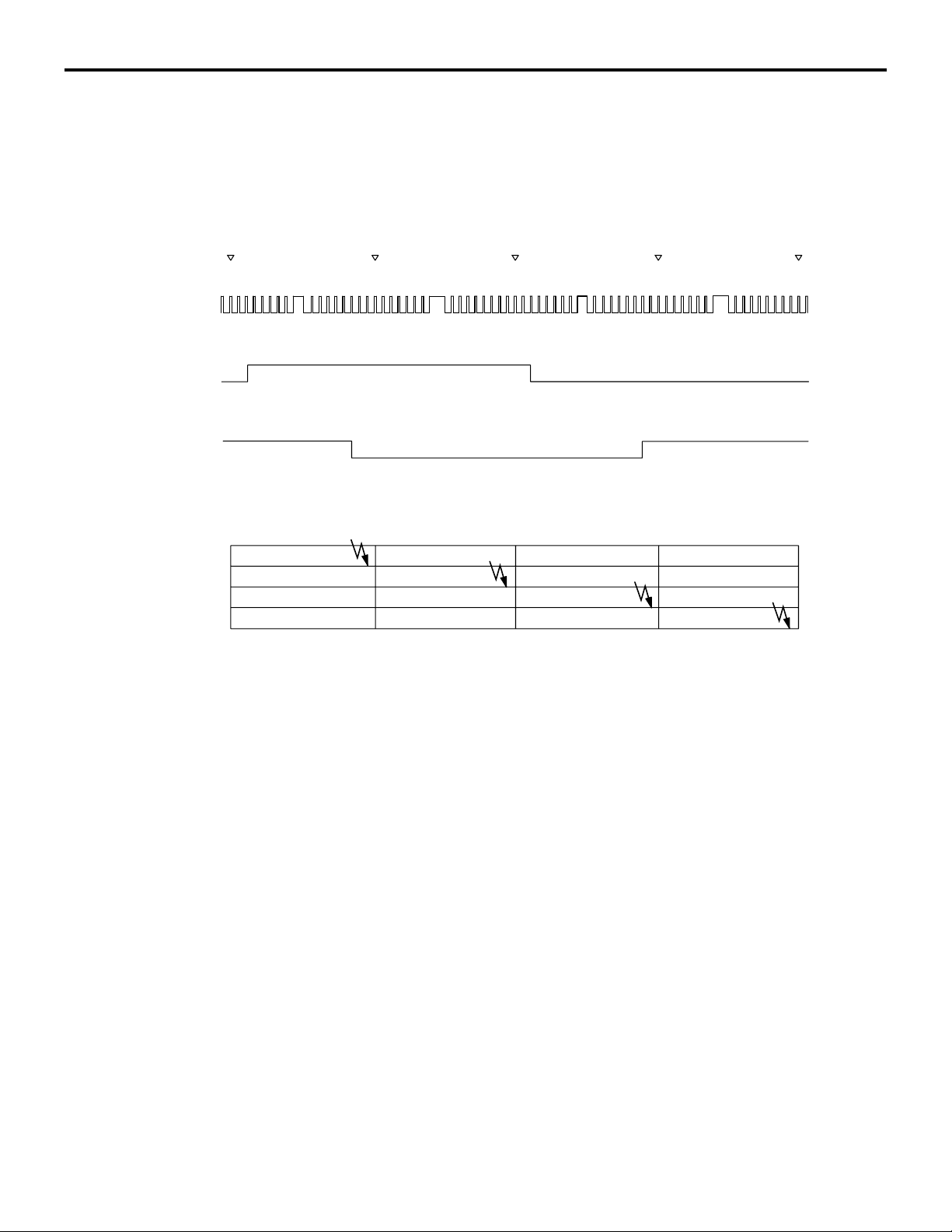
13A-36
MULTIPORT FUEL SYSTEM (MFI)
IGNITION TIMING AND CONTROL FOR CURRENT CARRYING TIME
1. Ignition distribution control
Based on the crankshaft position sensor signal and camshaft
position sensor signal, ECM decides the ignition cylinder, cal
culates the ignition timing and sends the ignition coil primary
current connect/disconnect signal to the power transistor of
each cylinder in the ignition sequence.
<No. 2 TDC> <No.1 TDC> <No. 3 TDC> <No. 4 TDC> <No. 2 TDC>
-
Crankshaft
position
sensor signal
Intake camshaft
position sensor
signal
Exhaust camshaft
position sensor
signal
Cylinder stroke
No. 1 Cylinder
No. 3 Cylinder
No. 4 Cylinder
No. 2 Cylinder
H
L
H
L
H
L
Ignition
Compression
Intake
Exhaust
Combustion
Combustion
Compression Combustion
Intake
Exhaust
Exhaust
Compression
Intake
Intake
Exhaust
Combustion
Compression
AK604624
AB
Page 86

MULTIPORT FUEL SYSTEM (MFI)
IGNITION TIMING AND CONTROL FOR CURRENT CARRYING TIME
2. Spark-advance control and current carrying
time control
.
[During start]
ECM initiates ignition at fixed ignition timing (5° BTDC) synchronized with the crankshaft position sensor signal.
.
[During normal operation]
After determining the basic spark-advance based on the intake
air volume and engine speed, ECM makes compensations
based on input from various sensors to control the optimum
spark-advance and current carrying time.
List of main compensations for spark-advance control and current carrying time control
Compensations Content
Intake air temperature compensation Compensation is made according to intake air
temperature. The higher the intake air temperature
the greater the delay in ignition timing.
13A-37
Engine coolant temperature compensation Compensation is made according to engine coolant
temperature. The lower the engine coolant
temperature the greater the advance in ignition
timing.
Knocking compensation Compensation is made according to generation of
knocking. The greater the knocking the greater the
delay in ignition timing.
Stable idle compensation Compensation is made according to change in idle
speed. In case engine speed becomes lower than
target speed, ignition timing is advanced.
Delay compensation when changing shift During change of shift, sparking is delayed
compared to normal ignition timing to reduce
engine output torque and absorb the shock of the
shift change.
Battery voltage compensation Compensation is made depending on battery
voltage. The lower the battery voltage the greater
the current carrying time and when battery voltage
is high current carrying time is shortened.
.
[Control for checking ignition timing]
During basic ignition timing set mode for M.U.T.-III actuator test
function, sparking is done with fixed ignition timing (5
synchronized with crankshaft position sensor signal.
° BTDC)
Page 87
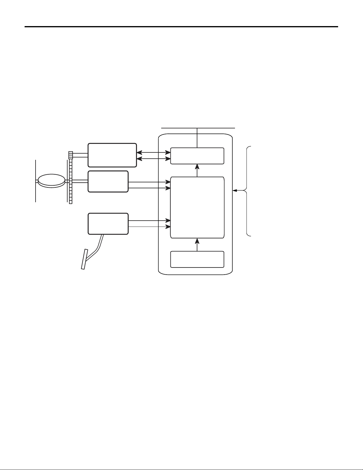
13A-38
THROTTLE VALVE OPENING ANGLE CONTROL AND IDLE SPEED CONTROL
MULTIPORT FUEL SYSTEM (MFI)
THROTTLE VALVE OPENING ANGLE CONTROL AND IDLE
SPEED CONTROL
ECM detects the amount of accelerator pedal
depression (as per operator's intention) through the
accelerator pedal position sensor. Based on pre-set
basic target opening angles it adds various compen
sations and controls the throttle valve opening angle
according to the target opening angle.
Motor drive power supply
(From throttle actuator
control motor relay)
Throttle actuator
control motor
Throttle
position
sensor
Accelerator
pedal position
sensor
Main
Sub
Sub
Main
-
Motor drive circuit
Control unit
M2132003500328
Engine coolant
temperature sensor
Intake air temperature
sensor
Crankshaft position sensor
A/C switch (CAN)
Power steering pressure
switch
Generator FR terminal
Transmission range
switch (CAN) <CVT>
While starting
ECM adds various compensations to the target
opening angle that are set based on the engine cool
ant temperature, so that the air volume is optimum
for starting.
While idling
ECM controls the throttle valve to achieve the target
opening angle that are set based on the engine cool
ant temperature. In this way best idle operation is
achieved when engine is cold and when it is hot.
Also, the following compensations ensure optimum
control.
Barometric pressure
sensor
ECM
AK602236AE
While driving
Compensations are made to the target opening
-
angle set according to the accelerator pedal opening
angle and engine speed to control the throttle valve
opening angle.
-
Page 88

MULTIPORT FUEL SYSTEM (MFI)
THROTTLE VALVE OPENING ANGLE CONTROL AND IDLE SPEED CONTROL
13A-39
List of main compensations for throttle valve opening angle and idle speed control
Compensations Content
Stable idle compensation (immediately after start) In order to stabilize idle speed immediately after
start, target opening angle is kept big and then
gradually reduced. Compensation values are set
based on the engine coolant temperature.
Rotation speed feedback compensation (while
idling)
Atmospheric pressure compensation At high altitudes atmospheric pressure is less and
Engine coolant temperature compensation Compensation is made according to the engine
Electric load compensation Throttle valve opening angle is compensated
Compensation when shift is in D range <CVT> When transmission is changed from P or N range
In case there is a difference between the target idle
speed and actual engine speed, ECM
compensates the throttle valve opening angle
based on that difference.
the intake air density is low. So, the target opening
angle is compensated based on atmospheric
pressure.
coolant temperature. The lower the engine coolant
temperature the greater the throttle valve opening
angle.
according to electric load. The greater the electric
load, the greater the throttle valve opening angle.
to some other range, throttle valve opening angle is
increased to prevent reduction in engine speed.
Compensation when A/C is functioning Throttle valve opening angle is compensated
according to functioning of A/C compressor. While
A/C compressor is being driven, the throttle valve
opening angle is increased.
Power steering fluid pressure compensation Throttle valve opening angle is compensated
according to power steering functioning. When
power steering oil pressure rises and power
steering pressure switch is ON, the throttle valve
opening angle is increased.
Initialize control
After ignition switch turns OFF, ECM drives the throttle valve from fully closed position to fully open position and records the fully closed/open studied value
of the throttle position sensor (main and sub) output
signals. The recorded studied values are used as
studied value compensation for compensating basic
target opening angle when the engine is started next.
Page 89
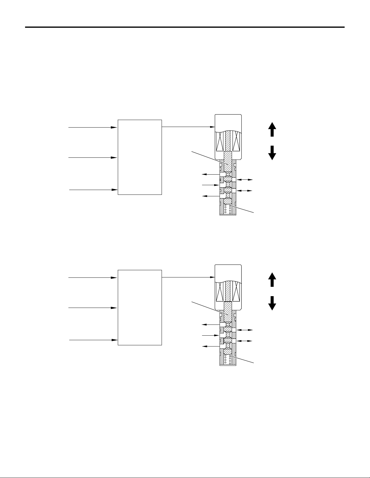
13A-40
MIVEC (Mitsubishi Innovative Valve Timing Electronic Control System)
MULTIPORT FUEL SYSTEM (MFI)
MIVEC (Mitsubishi Innovative Valve Timing Electronic
Control System)
MIVEC is the system which continuously varies and
controls the opening and closing timings of the intake
valve and the exhaust valve.
System Configuration Diagram
Crankshaft
position sensor
Manifold absolute
pressure sensor
Intake camshaft
position sensor
ECM
Spool valve
Oil pressure
Intake engine oil control valve
To oil pan
To oil pan
M2132023500212
Retard direction
Spool valve movement
Advance direction
Retard chamber
Advance chamber
Spring
Crankshaft
position sensor
Manifold absolute
pressure sensor
Exhaust camshaft
position sensor
ECM
Spool valve
MIVEC allows the optimum valve timing to be controlled in accordance with the engine operation and
the idling stability to be improved, as well as the out
put and the torque to be better in all the operation
ranges.
• The ECM assesses the engine operation through
the signals from each sensor.
Exhaust engine oil control valve
To oil pan
Oil pressure
To oil pan
• Based on the assessed information, the ECM
-
• Changing the spool valve position allows the oil
Advance direction
Spool valve movement
Retard direction
Advance chamber
Retard chamber
Spring
AK604826 AB
sends the duty signal to the intake engine oil con
trol valve and exhaust engine oil control valve as
well as controls the spool valve position.
pressure to be divided into the retarded chamber
and the advanced chamber, as well as allows the
phases of the intake camshaft and the exhaust
camshaft to be continuously changed.
-
Page 90
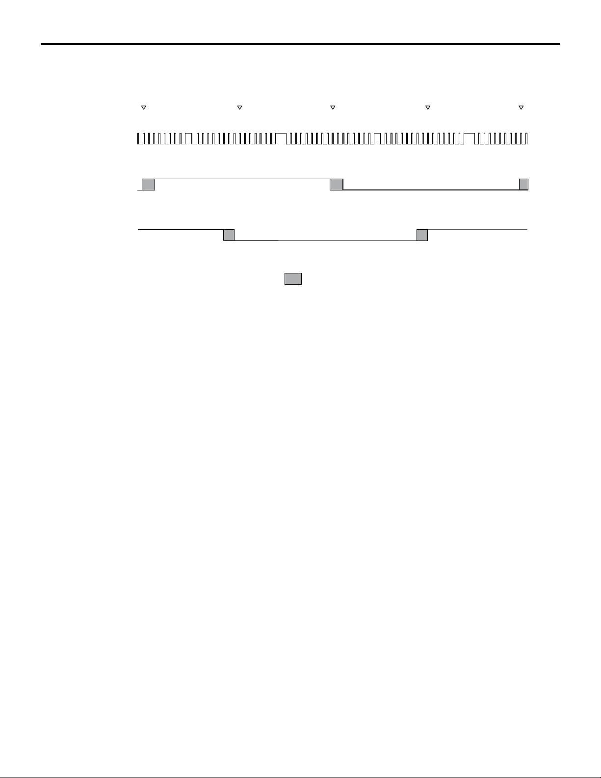
MIVEC (Mitsubishi Innovative Valve Timing Electronic Control System)
Phase Angle Detection
MULTIPORT FUEL SYSTEM (MFI)
13A-41
Crankshaft
position
sensor signal
Intake camshaft
position sensor
signal
Exhaust camshaft
position sensor
signal
<No. 2 TDC>
H
L
H
L
H
L
<No.1 TDC> <No. 3 TDC> <No. 4 TDC> <No. 2 TDC>
: phase angle
AK604625
AB
Page 91
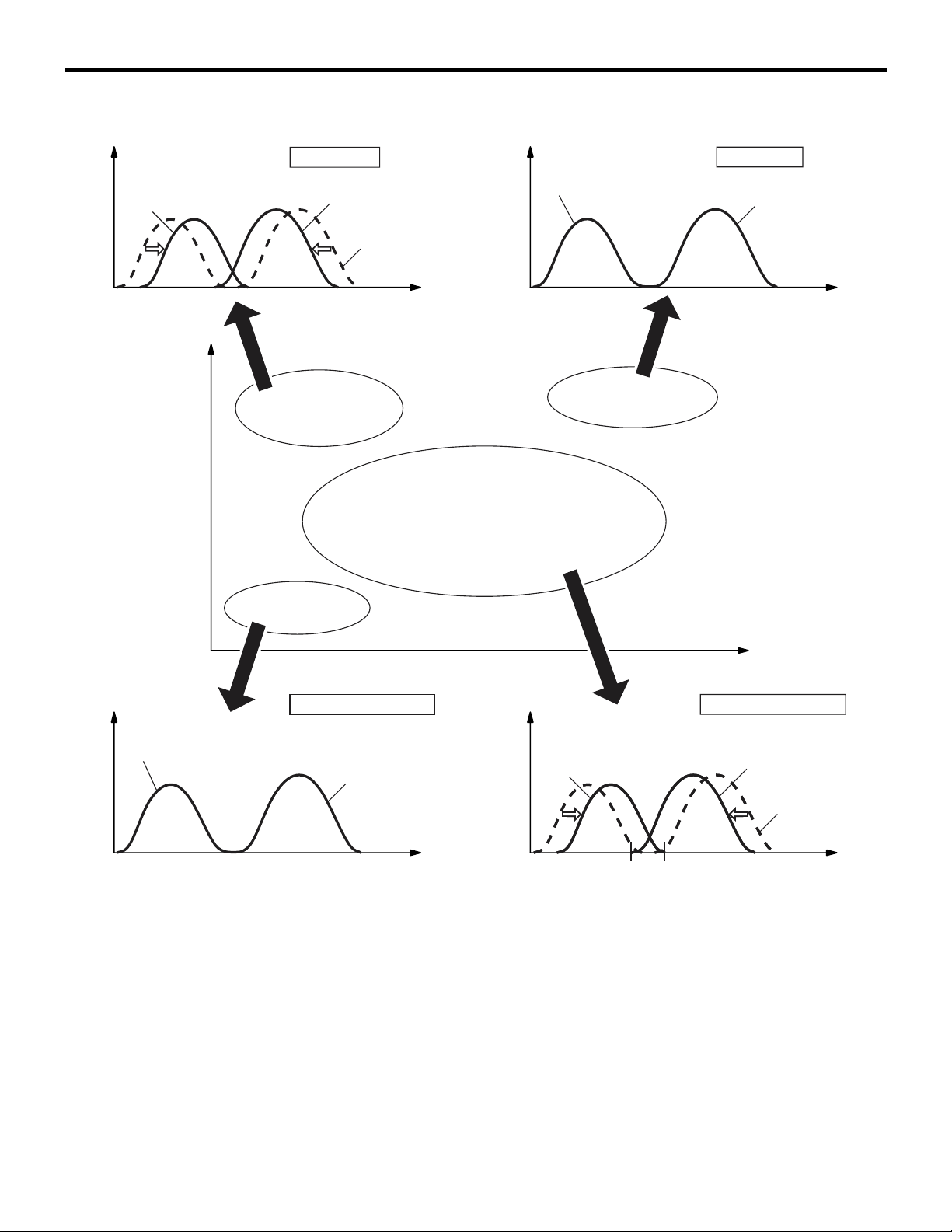
13A-42
MIVEC (Mitsubishi Innovative Valve Timing Electronic Control System)
MULTIPORT FUEL SYSTEM (MFI)
The detected phase angle is calculated using the cam position sensor signal.
Valve lift amountValve lift amount
Exhaust valve
High torque
Intake valve
Initial position
Exhaust valve
Crank angle Crank angle
High output
Intake valve
(initial position)
High load range at
low and middle speeds
Load
Middle load range
Low load range at
low speed
Engine speed
Valve lift amount Valve lift amount
Exhaust valve
(initial position: most advance)
Low-fuel consumption
Intake valve
(initial position: most retard)
Exhaust valve
High load range at
high speed
Low-fuel consumption
Intake valve
Initial position
Overlap: nothing <Except for California>
small <California>
Crank angle Crank angle
Overlap: large
AK604129
AB
Page 92
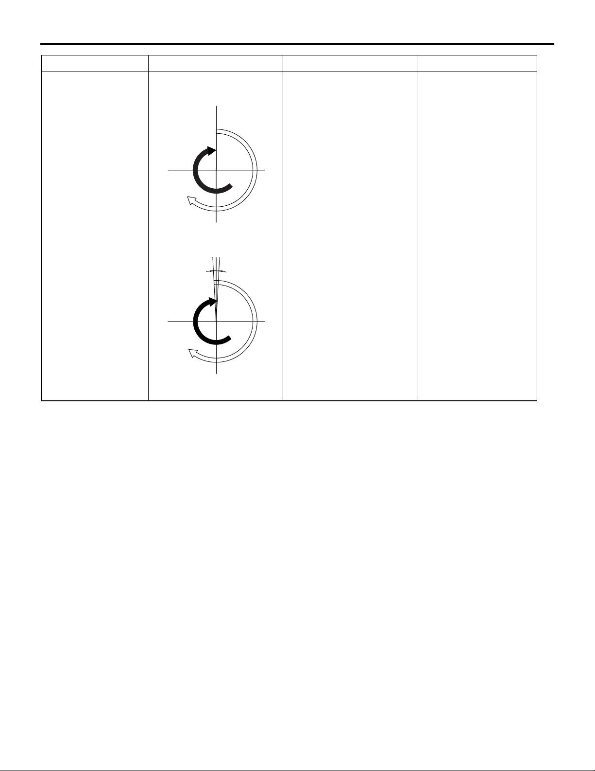
MULTIPORT FUEL SYSTEM (MFI)
MIVEC (Mitsubishi Innovative Valve Timing Electronic Control System)
Operation condition Valve timing Operation Effectiveness
Within range of low
speed and low load
at idle
<Except for California>
TDC
Overlap:
nothing
Exhaust valve
(initial position)
BDC
<California>
Overlap:
small
Exhaust valve
(initial position)
TDC
Intake valve
(initial position)
Intake valve
(initial position)
Overlap is decreased and
amount of exhaust gas
flowing back into intake
port is limited.
Idle speed stable
13A-43
BDC
AK604130 AB
Page 93
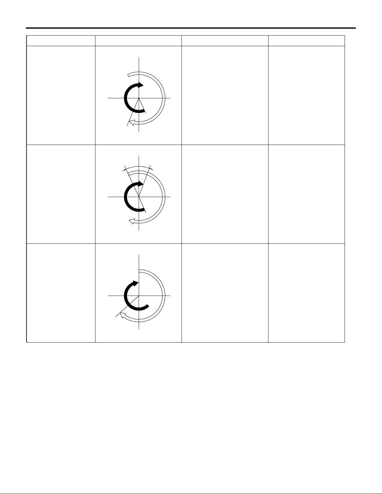
13A-44
MIVEC (Mitsubishi Innovative Valve Timing Electronic Control System)
MULTIPORT FUEL SYSTEM (MFI)
Operation condition Valve timing Operation Effectiveness
Within range of low
speed and high load
at acceleration
TDC
Intake valve
Exhaust valve
Advancing closing timing of
intake valve allows amount
of intake air flowing back
into intake port to be limited
as well as allows
Low and middle speed
torques improved
volumetric efficiency to be
improved, resulting in low
and middle speed torques
improved.
AB
Close
BDC
Open
AK604131
Within range of
middle speed and
middle load
Within range of high
speed and high load
Overlap:
large
Exhaust valve
Exhaust valve
Close
TDC
BDC
TDC
Open
Intake valve
AB
AK604132
Intake valve
Increasing overlap amount
allows pumping loss to be
decreased. Retarding
opening timing of exhaust
valve allows burned gas to
work sufficiently and allows
cycle efficiency to be
improved, resulting in
higher expansion ratio.
Retarding closing timing of
intake valve in accordance
with engine speed allows
valve timing to be
controlled according to
inertia force of intake air
and allows volumetric
efficiency to be improved.
Fuel economy
improved
Output improved
BDC
AK604133
AB
Page 94
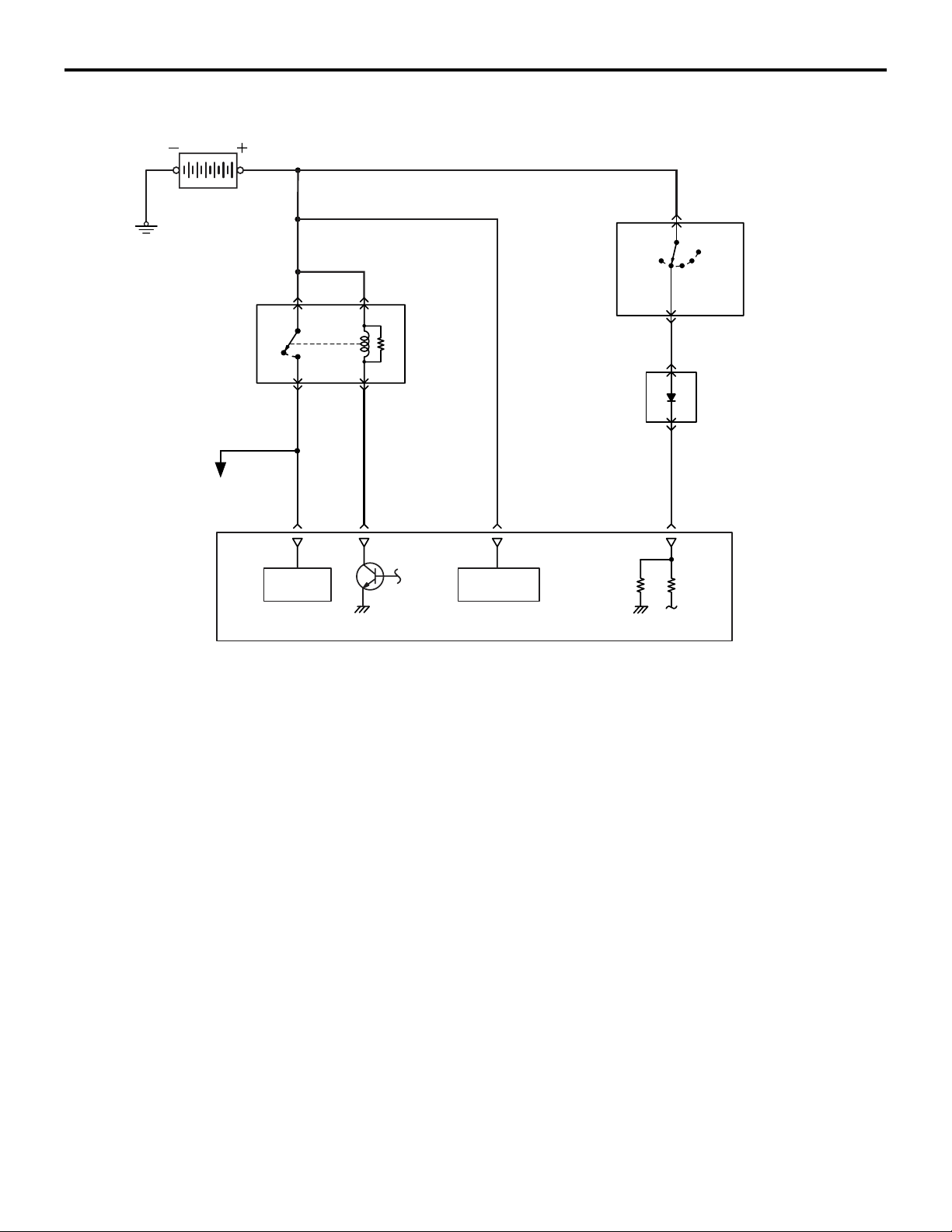
MULTIPORT FUEL SYSTEM (MFI)
MULTIPORT FUEL INJECTION (MFI) RELAY CONTROL
13A-45
MULTIPORT FUEL INJECTION (MFI) RELAY CONTROL
M2132006000173
Battery
LOCK
MFI relay
To each sensor and
actuator
OFF
ON
Ignition switch
ETACS-ECU
ST
IG1
ACC
IG2
Powe r
supply
MFI relay control Ignition switch-IG
When the ignition switch-IG "ON" signal is input,
ECM turns ON the power transistor for control of the
MFI relay. As a result, current flows through the MFI
relay's coil, the relay switch turns ON and power is
supplied to each sensor and actuator. Also, when
ignition switch-IG "OFF" signal is input, ECM per
forms the following controls and then turns OFF the
power transistor for control of MFI relay.
Battery
back up
• Throttle valve initializing control
ECM
AK604134AB
Page 95
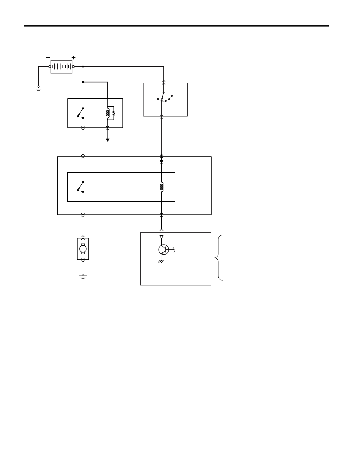
13A-46
MULTIPORT FUEL SYSTEM (MFI)
FUEL PUMP RELAY CONTROL
ETACS
-ECU
Battery
MFI
relay
OFF
OFF
FUEL PUMP RELAY CONTROL
ON
ON
To ECM
ST
IG1
IG2
LOCK
ACC
Ignition switch
Fuel pump
relay
M2132006500208
Fuel pump
M
ECM
Fuel pump
relay control
When current flows through the fuel pump relay, the
relay turns ON and the fuel pump is driven. The fuel
pump relay is built into the ETACS-ECU. When the
ignition switch-ST signal is input, ECM turns ON the
power transistor for control of the fuel pump relay. As
Ignition switch-ST
Crankshaft position sensor
AK604135
AB
a result, power is supplied to the fuel pump. Also, if
engine speed falls below a set value, the fuel pump
relay is turned OFF. Thus, it deals with sudden stop
pages such as engine stalling etc. by stopping the
pump.
-
Page 96
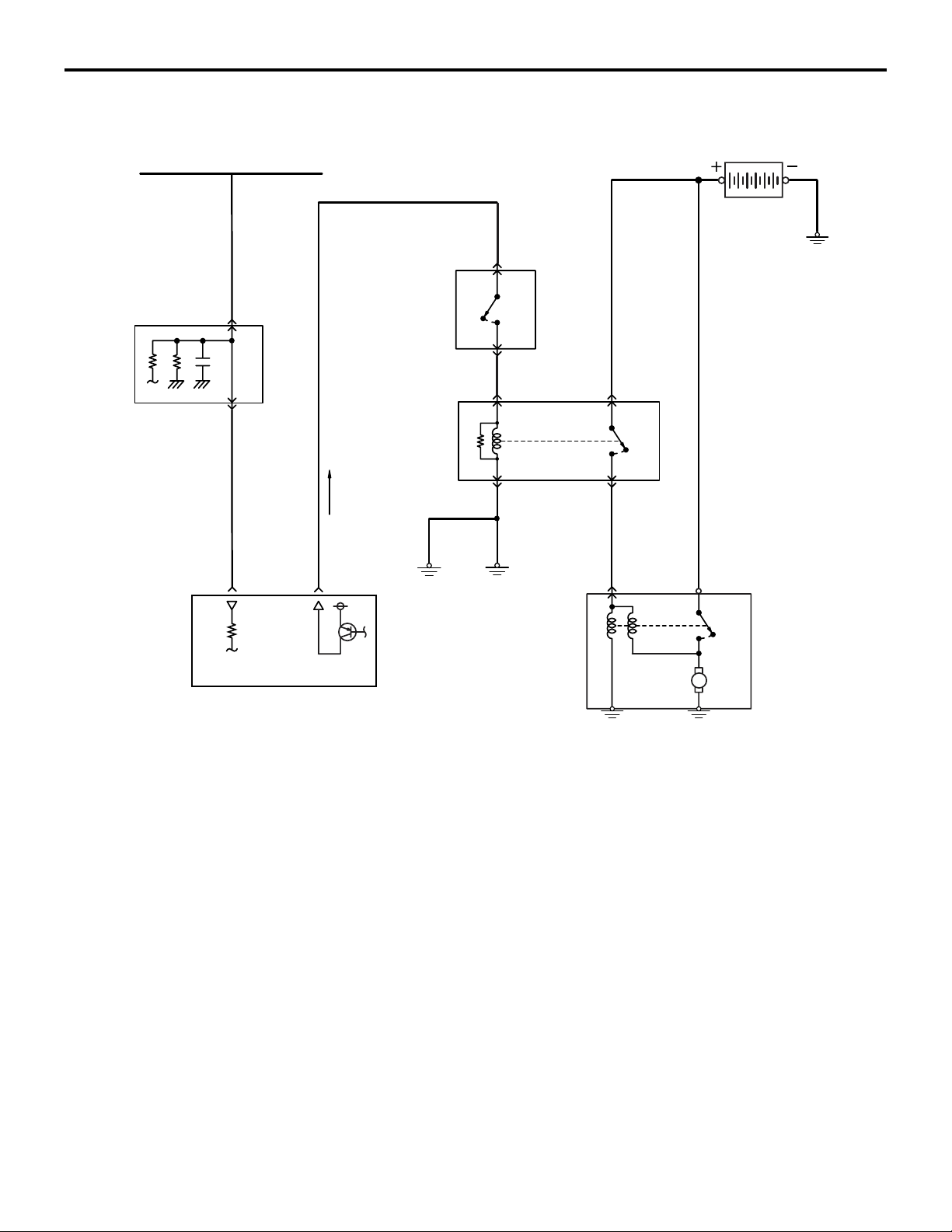
MULTIPORT FUEL SYSTEM (MFI)
STARTER RELAY CONTROL
13A-47
<M/T>
ETACS
-ECU
Ignition switch-ST
STARTER RELAY CONTROL
Clutch
interlock
switch
Starter relay
OFF
ON
OFF
ON
M2132025500092
Battery
Engine-ECU
Starter relay
control
ON
OFF
M
Starter
AK604136
AB
Page 97
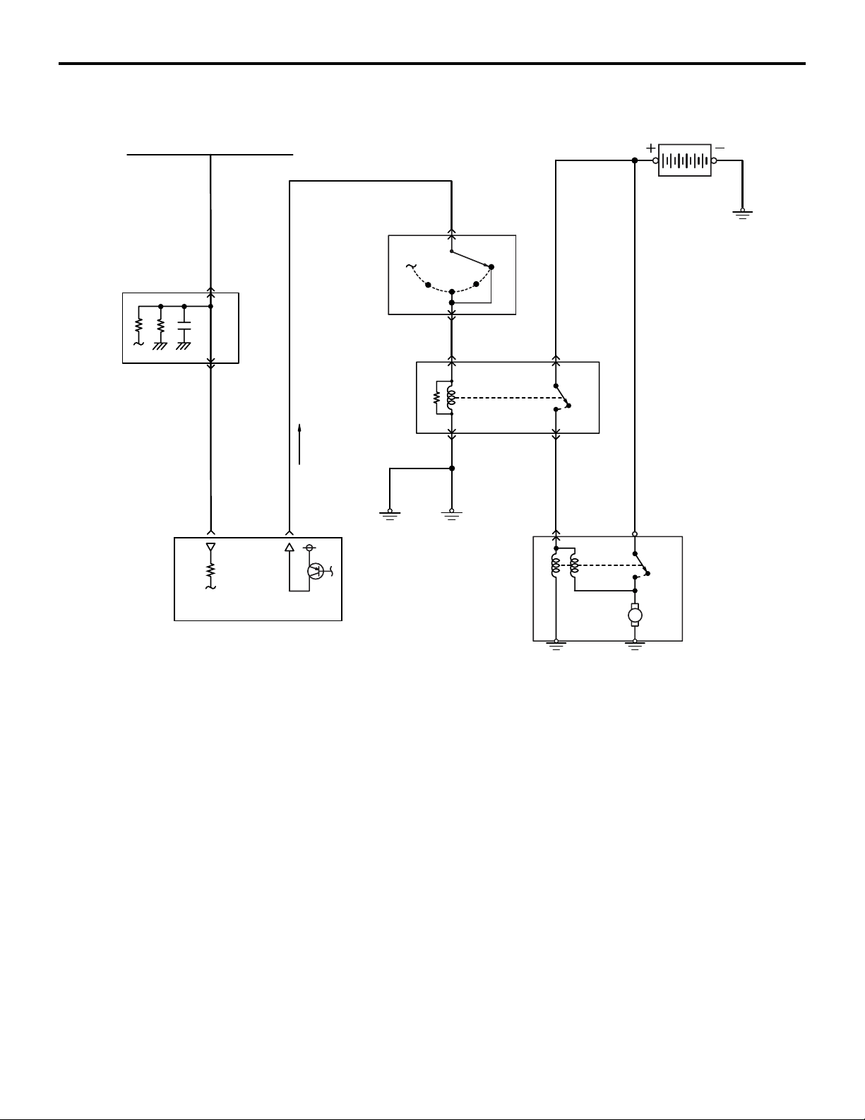
13A-48
<CVT>
MULTIPORT FUEL SYSTEM (MFI)
STARTER RELAY CONTROL
ETACS
-ECU
Ignition switch-ST
Transmission
range switch
Starter relay
Battery
P
R
N
D
OFF
ON
Engine-ECU
Starter relay
control
When the ignition switch-ST signal is input, ECM
turns ON the power transistor for control of the
starter relay.
ON
OFF
M
Starter
AK604137
AB
Page 98
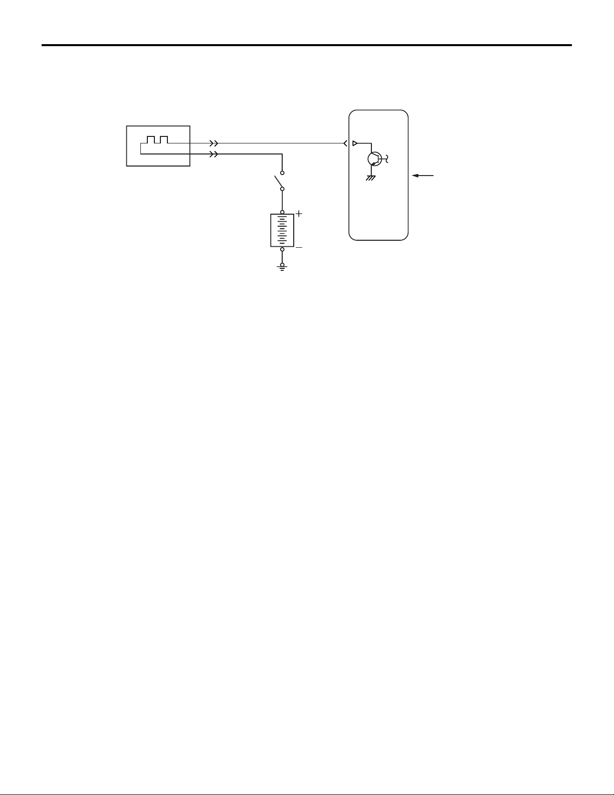
MULTIPORT FUEL SYSTEM (MFI)
HEATED OXYGEN SENSOR HEATER CONTROL
13A-49
HEATED OXYGEN SENSOR HEATER CONTROL
Heated oxygen sensor heater
MFI relay
Battery
When exhaust gas temperature is low, the heated
oxygen sensor response is dull. So, response is
improved by raising the sensor temperature by pass
ing current through the heater at a low exhaust gas
temperature, such as in the immediate aftermath of
the engine start, or during the warm up operation and
M2132007000206
ECM
Engine coolant
temperature sensor
AK602241AD
in cutting the fuel during deceleration. Based on driv
ing conditions and the heated oxygen sensor activa-
-
tion state, ECM changes the amount of current (duty
ratio) to the heater to quicken the activation of the
heated oxygen sensor.
-
Page 99
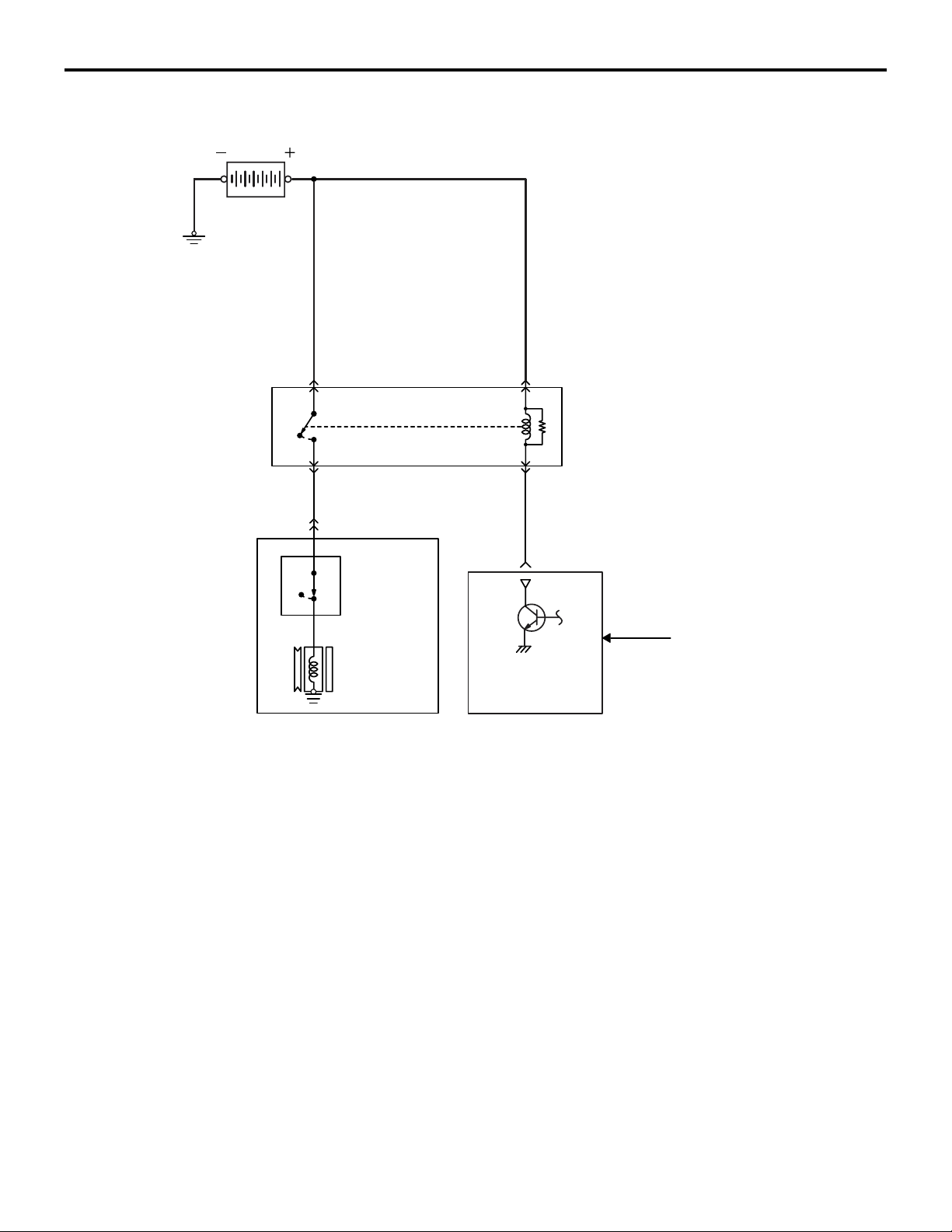
13A-50
MULTIPORT FUEL SYSTEM (MFI)
A/C COMPRESSOR RELAY CONTROL
A/C COMPRESSOR RELAY CONTROL
Battery
A/C compressor relay
M2132034500120
OFF
ON
A/C
refrigerant
OFF ON
A/C compressor
assembly
temperature
switch
A/C compressor
clutch
The ECM turns on the power transistor when the A/C
switch ON signal is input by the A/C-ECU through
the CAN. This allows the A/C compressor relay to be
ON and to be operated. During the high load opera
tion, such as the acceleration with the fully opened
accelerator, the ECM secures the acceleration capa
bility by turning off the A/C compressor relay for the
specified period to produce no load on the A/C com
pressor.
A/C compressor
relay control
-
-
ECM
A/C switch (CAN)
AK604138
AB
Page 100
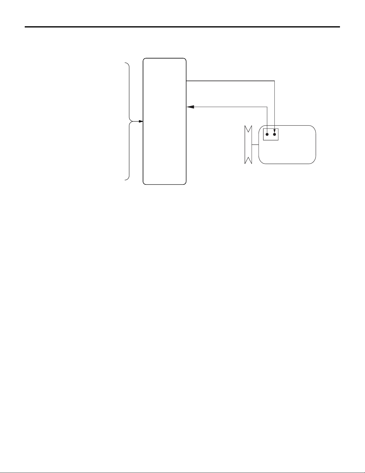
MULTIPORT FUEL SYSTEM (MFI)
GENERATOR CONTROL
13A-51
GENERATOR CONTROL
Engine coolant temperature sensor
Crankshaft position sensor
ECM
A/C switch (CAN)
Ignition switch-ST
During engine idle operation, ECM controls duty of
conduction between generator G terminal and
ground. (G terminal duty is controlled to be the same
as ON duty of the power transistor inside the voltage
regulator). If headlights etc. are turned on while
engine is idling, the consumed current increases
suddenly, but by gradually increasing the generator
M2132025000172
Generator G terminal
Generator FR terminal
Generator
AK602242AD
G terminal OFF duty, ECM restricts sudden increase
in generator's output current and output current is
increased only gradually. (Battery current is supplied
to the headlamp etc. till generator produces sufficient
current.) Thus, ECM prevents change in idle speed
due to sudden increase of engine load.
 Loading...