

Mitsubishi Electric JT-SB116EH-W-CA Installation Manual

The Instruction Manual and Usage Sticker are for the customer, and should be handed over together with the unit.
Read this manual thoroughly before beginning installation to ensure the unit is installed safely and correctly.
Local installation standards should be obeyed and installation should be performed by a qualified professional.
Installation Manual
Hand Dryer
Model
JT-SB116EH-W-CA
Single-phase 120VAC
0612874HD7001
GB
For dealers and installers
Do not disassemble
Do not use in shower room
Use a single-phase alternating current 120V power supply.
Voltage in excess of 120V+10% may cause mechanical failure, so stay within the rated range.
Using an incorrect power supply may cause fire, electric shock, or malfunction.
Electrical wiring work should be done by a certified professional in conformance with local standards.
Incorrect wiring can cause electric shocks and fire.
Be sure to install a ground-fault circuit interrupter.
Lack of one may cause electric shock.
A means for disconnection must be incorporated in the fixed wiring in accordance with the wiring rules.
This appliance is not intended for use by young children or infirm persons unless they are adequately
supervised by a responsible person to ensure that they can use the appliance safely.
Young children should be supervised to ensure that they do not play with the appliance.
Do not modify or disassemble more than necessary.
This may cause fire, electric shock, or injury.
Do not install in shower room or other locations with a great deal of humidity in the air, where
condensation may form on the unit, or where the unit may come in direct contact with water.
This may cause electric shock or malfunction.
Important!
Follow instructions
Safety precautions
Grounded connection
Be sure the unit is properly grounded.
Lack of a proper ground may cause electric shock during malfunction or short circuit.
WARNING
The following may lead to death or serious
personal injury if done incorrectly.
CAUTION
The following may lead to injury or damage to
buildings or their contents if done incorrectly
Do not attempt installation with the power on in the unit (supply mains).
This may cause electrical shock.
Do not remove the heater.
It may cause fire, electric shock or injury.
Do not use at locations where salt damage may occur or where corrosive, neutral or reductive gas
are present.
Failure to do any of the above may cause fire, electric shock or trouble.
Prohibited
Do not install the unit in places where vandalism might occur.
Vandalism may cause malfunction.
Install in a location strong enough to support the weight of the unit.
Injury may be cause by the unit falling.
Wear gloves when installing the unit.
Not doing so may cause injury.
Important!
Follow instructions
Test r
1
2
3
4
5
6
7
8
*
*
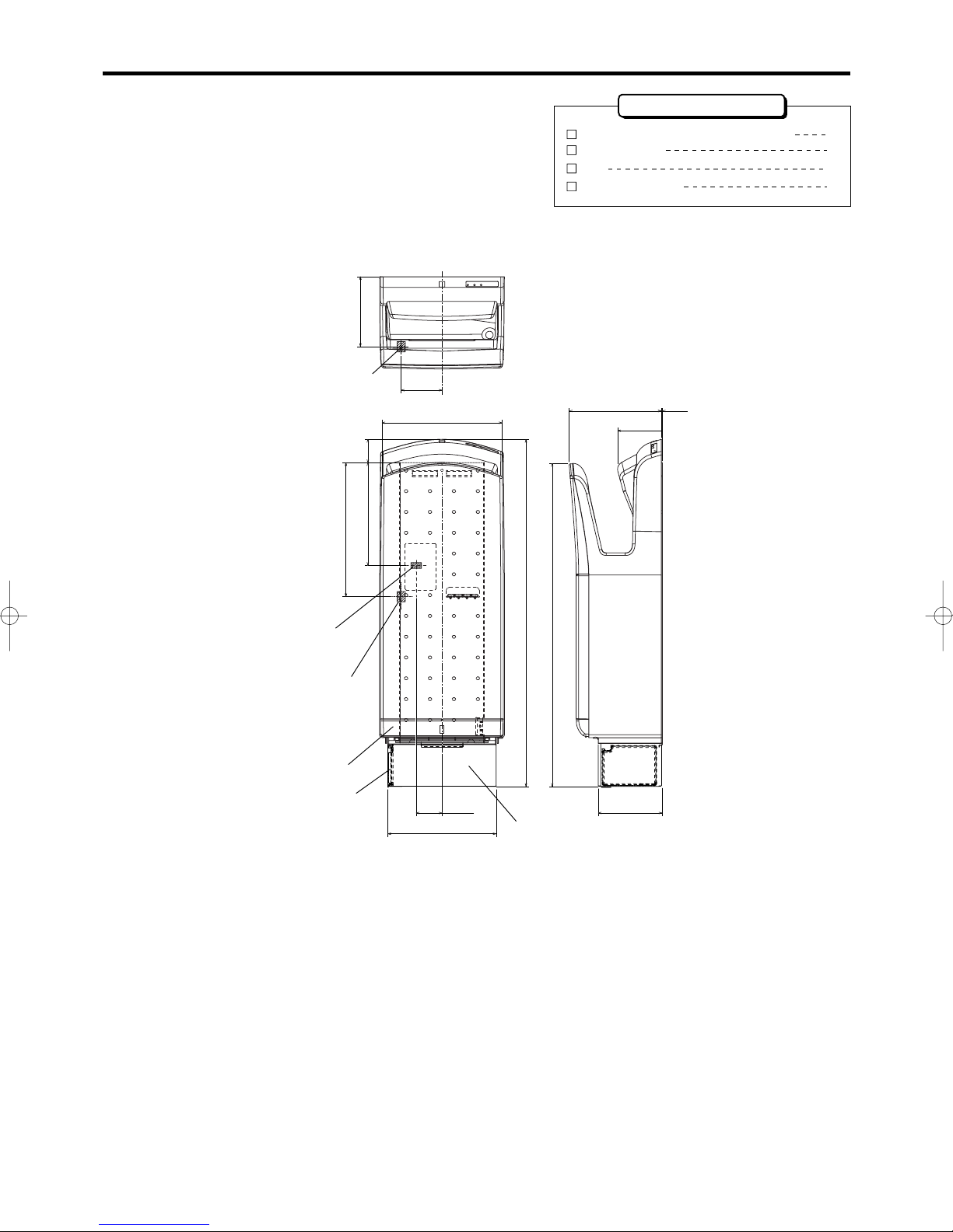
Names and Dimensions of Parts
Installation panel screws (5x30 self-tapping) 6
Installation panel 1
Clip 1
Accessories
98
169
Drain tank
Heater
Unit:mm
Air filter
Power cord hole (rear)
Terminal block
Terminal block
247
835
62 152
56
322
260
300
777
222
2
106
Clip mounting screw 1
2
When installing
Do not install in the following types of location, as this may cause malfunction.
●
●
●
●
●
●
●
●
Locations where the temperature could be lower than 0˚C or higher than 40˚C.
Locations where the humidity could be lower than 5%RH or higher than 95%RH.
Locations where the unit may come into direct contact with water.
Locations where the unit is under direct or strong sunlight. (May cause sensor to malfunction.)
Locations where there is a lot of condensation.
Locations where corrosive, neutral, or reductive gases are present.
Locations where salt damage may occur.
Vehicles (incl. vessels, trains.)
Installation location
●
●
●
●
●
●
●
●
Install the unit somewhere easy to use, as shown below.
If the unit is installed too low, water may get on it when the floor is being cleaned.
If water gets inside, it may damage the unit or moisten the sound-absorbent material, leading to bacterial growth.
The left side of the unit must be at least 150 mm away from any walls, as that is where the power switch is located.
Ensure there are no mirrors or walls near the right side, as drops of water may splash when drying hands.
(We recommend a distance of at least 100 mm.)
Avoid locations where people or doors might bump into the unit.
Choose a completely flat surface on the wall to install the unit.
If the wall is not concrete, reinforce it before installation.
Avoid to install the unit any place where foods, tableware, or the likes are handled nearby because water may
splash.
Do not embed the unit in the wall.
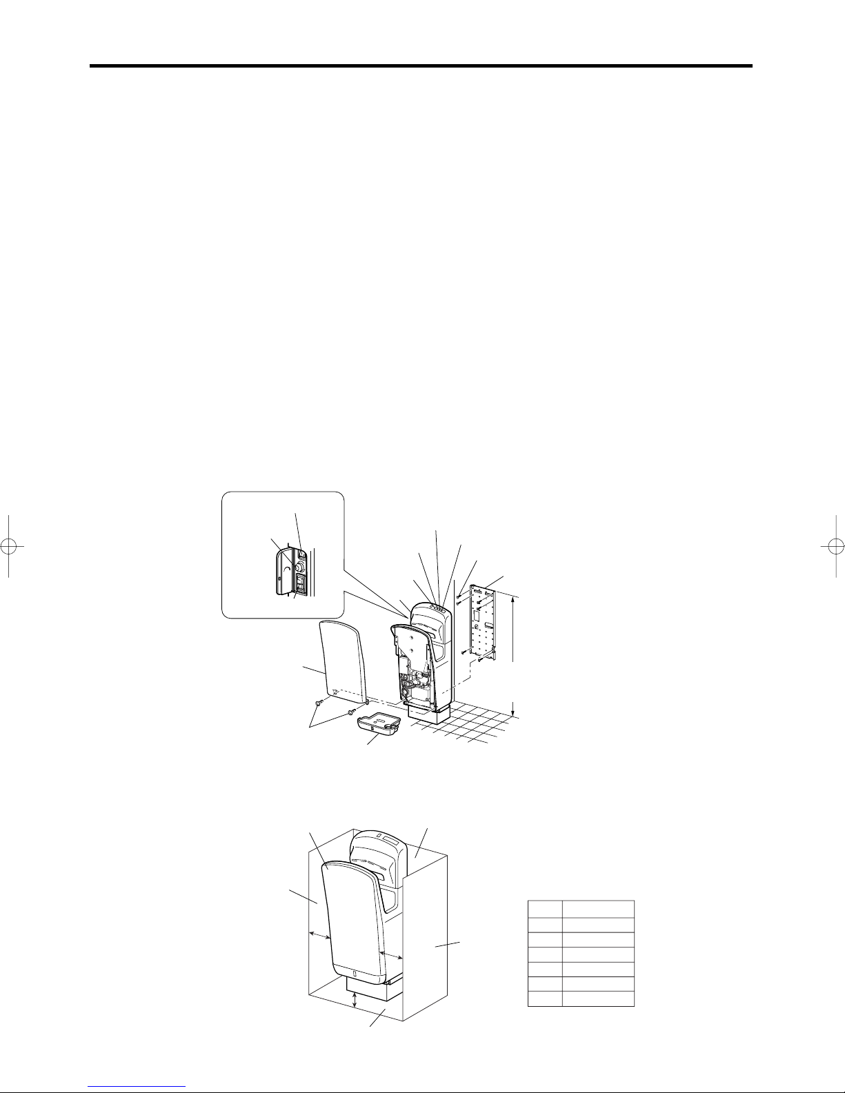
Make sure to secure distances larger than those listed below away from walls of building, etc.
Location
Clearance
Top
Left
Right
Front
Rear
Bottom
Open
150
mm
100
mm
Open
–
140
mm
Rear face
hand dryer
Right face
Bottom face
Left face
100
150
140
Unit (mm)
Power controll section
Drain tank
Front panel
Unit
Installation panel screw
Installation panel
Check lamp
Heater lamp
Heater switch
Power lamp
Display
Front panel
mounting screws
Power switch
Air speed
knob
Recommended installation heights:
Men: 940 mm
Women: 920 mm
3
-
+
O
F
F
O
N
O
F
F
O
N
Po
w
er
A
ir
s
p
e
e
d
H
eater
 Loading...