

Page 1

MITSUBISHI
IPM SPINDLE DRIVE SYSTEM
SJ-PM Series
MDS-B-SPM Series
SPECIFICATION MANUAL
BFN-15979B
Page 2
MITSUBISHI ELECTRIC CO.
(
)
p
NC SERVO SYSTEM ENGINEERING
1. Outline
This procedure is to inform about the “Setting and Attention item” regarding Mitsubishi’s IPM
(Internal Permanent Magnet) type Spindle Motor and Drive Unit.
For the general items that are not mentioned in this book, please refer to our "Built-In AC Spindle
Drive Specification Manual (BFN-14118-04-A)" and "AC Servo and Spindle Drive Unit MDS-A/B series
Specification Manual (BNP-B3759B)".
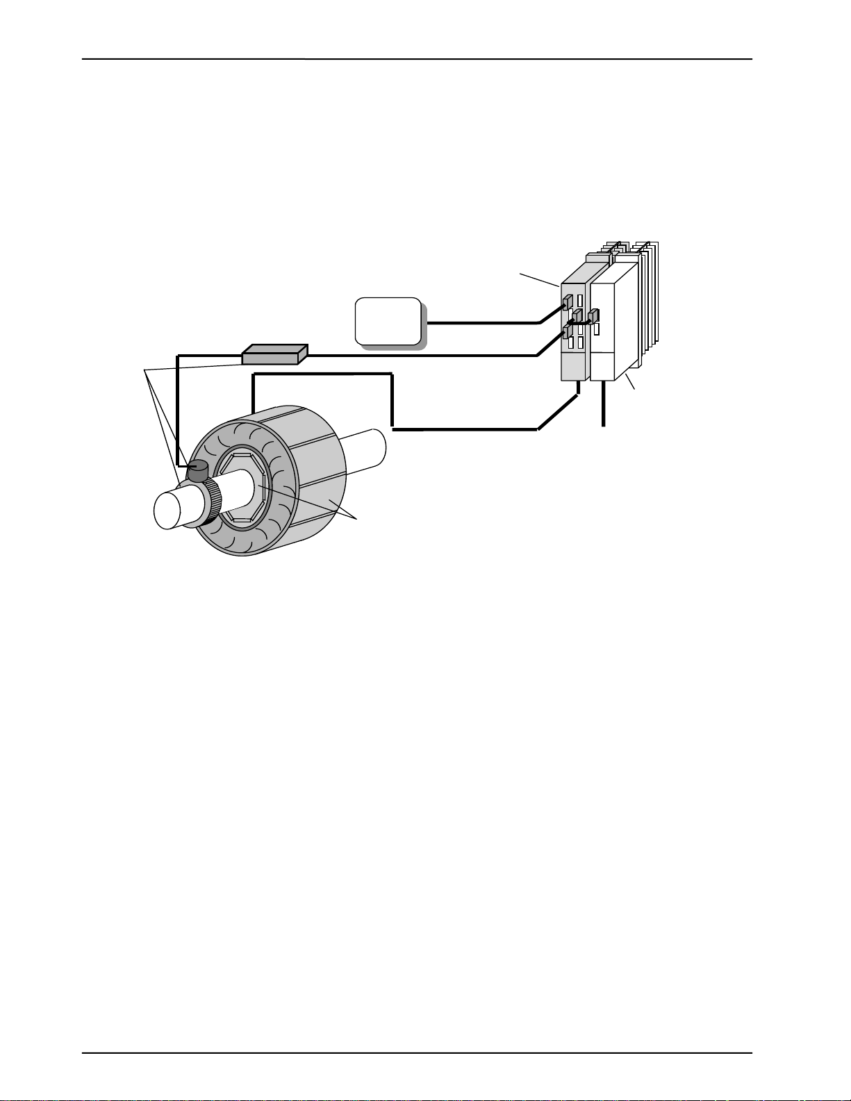
2. System configuration
Pre-Am
.
CNC
IPM Spindle Drive Unit
(MDS-B-SPM)
PLG
3. Amplifier
Fee d B a c k C a b le (A,B,Z )
Power Supply Unit
MDS-B-CV
Pow e r C a ble (U ,V,W) AC 20 0 [V]
IPM Spindle Motor
(SJ-PM)
3-1. Wiring
Wiring and connections are the same as Spindle Drive Unit "MDS-B-SP".
3-2. Parameter setting
<Related Parameters which are now used>
SP205(ZCHS) ・・・・・・・・・ Effective during "Automatic Z-Phase PLG Adjustment Function "
(0 : Invalid / 1 : Effective). 1 is set at normal operation.
SP245(PGHS) ・・・・・・・・・ Effective during "Automatic PLG Adjustment Function "
(0 : Invalid / 1 : Effective).
3-3. Automatic Z-Phase PLG Adjustment
This adjustment must be performed anytime spindle hardware is replaced.
(Spindle Amp, Motor, PLG, etc.)
"Automatic Z-Phase PLG Adjustment" is used to adjust the relative position of the motors
magnetic poles and the Z-Phase pulse signal. This data is then memorized in the MDS-B-SPM.
The purpose of this function is to improve the output torque to achieve a more precise calculation.
After this process has been completed during the first installation, it will be required to do again using
the following procedure when any spindle hardware is replaced.
<Notice>
※1 Before starting, check and or adjust the mechanical alignment between the detector gear and
sensor for proper gap setting.
※2 Before starting, remove any load (GD
it as much as possible (max. 5 times motor GD
2
)or friction that may be applied to the Spindle, or reduce
2
).
- 1 -
Page 3

MITSUBISHI ELECTRIC CO.
NC SERVO SYSTEM ENGINEERING
※3 During the Automatic Z-Phase PLG adjustment, the motor will turn automatically at the
adjustment RPM.
※ 4 If the system is started without implementing this procedure, the protection function is
activated and Alarm 16 will occur.
※ 5 Make sure to properly adjust the A & B phase zero volt offset and the 3 volts P-P levels with
an oscilloscope using the adjustment potentiometers BEFORE starting the auto adjustment
procedure. Also, make sure you have the Z phase marker pulse by a visual on the oscilloscope.
(1) Change the parameter : SP205 from 1 to 0, cycle power then set SP205 from 0 to1 and proceed to
step 2. If already set to 0, change to 1 and cycle power.
(2) Start spindle at approx. 200RPM (CW direction).
(3) The Spindle motor turns automatically at the speed for the adjustment.
(4) The adjustment result is computed within about 90 seconds after starting (time depends on
starting position). Spindle stops automatically when completed.
(5) After the spindle stops, cycle the power once more.
If it is required to do the Automatic Z-Phase PLG adjustment once again, Set 0 into parameter
SP205 and implement once again from 3-3 ※1. There is only one chance to do the Automatic Z-Phase
PLG Adjustment after parameter SP205 is changed. Process can be performed repeatedly after the
parameter is changed and power is cycled.
Never touch the Motor Shaft or anywhere near the Motor
.
3-4. Automatic PLG Adjustment for the MDS-B-SPM
This adjustment must be performed anytime spindle hardware is replaced.
(Spindle Amp, Motor, PLG, etc.)
"Automatic PLG Adjustment” is used to adjust the Offset and Gain for the A and B phase sine wave
signal of the PLG. This data is then memorized in the MDS-B-SPM.
The purpose of this function is to improve the position data to achieve a precise calculation. After
this process has been completed during the first installation, it will be required to do again using the
following procedure when any spindle hardware is replaced.
<Notice>
※1 Before starting, check and or adjust the mechanical alignment between the detector gear and
sensor for proper gap setting.
※2 Before starting, remove any load (GD
it as much as possible (max. 5 times motor GD
※3 During the Automatic Z-Phase PLG adjustment, the motor will turn automatically at the
adjustment RPM.
※4 If the system is started without implementing this procedure, the protection function is
activated and Alarm 16 will occur.
(1) Change the parameter : SP245 from 1 to 0, cycle power then set SP245 from 0 to1 and proceed to
step 2. If already set to 0, change to 1 and cycle power.
(2) Start spindle at approx. 200RPM (CW direction).
(3) The Spindle motor turns automatically at the speed for the adjustment.
(4) The adjustment result is computed within about 50 seconds after the starting. Spindle stops
automatically when completed
(5) After the spindle stops, cycle the power once more.
If it is required to do the Automatic PLG adjustment once again, Set 0 into parameter SP245 and
implement once again from 3-4 ※1. There is only one chance to do the Automatic PLG adjustment after
parameter SP245 is changed. Process can be performed repeatedly after the parameter is changed and
power is cycled.
2
)or friction that may be applied to the Spindle, or reduce
2
).
Never touch the Motor Shaft or anywhere near the Motor
.
- 2 -
Page 4

MITSUBISHI ELECTRIC CO.
NC SERVO SYSTEM ENGINEERING
3-5. Alarm
<Alarm which was occurred in Automatic Adjustment>
AL16 :Magnetic Pole Position detection malfunction. (Similar to servo alarm #16)
( It occurs when starting without Automatic Z-Phase Adjustment.)
AL42 :Feed back Signal malfunction
( It occurs when detecting incorrect Z-Phase Pulse signal.)
AL3F : Rotation error detection function alarm.
( This alarm was added to prevent motor damage due to missing or bad speed FB
signal during adjustment)
Perform the outlined adjustments above in 3-3 and 3-4 to remove the alarm condition.
4. Motor
4-1. Safekeeping
Store the motor in the packaging material until ready for installation.
< Warning>
(1) The rotor used for this motor is a powerful permanent magnet.
(2) Especially in case of the built in type motor, the material is one that produces a very strong
magnetic field and will influence the magnetic pull onto the nearby substances. Damage will
result to the compositions that are affected by the magnetism such as clocks, magnetic storage
media, etc.
4-2.Construction (Built-in type)
(1) The rotor is a powerful permanent magnet.
Caution needs to be exercised when inserting the rotor shaft into rotor or when installing the motor
into the machine giving particular attention to clear hands and fingers.
(2) Do not drop or impact the stator and rotor.
When an impact is made to the stator, the insulation material can be damaged resulting in the
windings becoming damaged or burnt under loaded conditions.
When an impact is made to the rotor, the magnetic capacity is reduced and damage to the material
can occur.
(3) When installing the shaft into the rotor, do not allow the rotors temperature to exceed 130°C,
which is the upper limit of the rotors heating temperature.
If the rotors temperature rises above this limit, demagnetization will occur.
- 3 -
Page 5

MITSUBISHI
IPM SPINDLE DRIVE SYSTEM
SJ-PM Series
MDS-B-SPM Series
SPECIFICATION MANUAL(BFN-15979B)
Background of revision
Version Date Contents
* Sept.04.1998 beginning
A Feb.07.2000 AL42 was added in 3-5.Alerm.
B Nov.14.2001 AL3F was added and doc was revised for better understanding
MITSUBISHI ELECTRIC CO.
NC SERVO SYSTEM ENGINEERING
- 4 -
 Loading...