

Mitsubishi Electric Jet Towel JT-SB116JH-G-NA, Jet Towel JT-SB116JH-W-NA Installation Manual
− 1 −
Model Name
Display Position.
Power voltage
display position.
The "INSTRUCTION MANUAL" is for the customer. Be sure to hand it to the customer.
For Dealers and Installers
INSTALLATION MANUAL
Hand dryer
Read this manual thoroughly before beginning installation to ensure the unit is installed safely and correctly.
Local installation standards should be obeyed and installation should be performed by the dealer or a qualifi ed
professional.
INDEX
Safety Precautions …………………………………………………… 2
Pre-installation checks ……………………………………………… 3
■ Checking the installation environment
………………………………… 3
■ Check the unit, accessories, and items required for installation
………… 3
■ Check the heater settings and air speed settings
……………………… 3
Names of parts and external dimensions ………………………… 4
Installation conditions ………………………………………………… 5
■ Required space for installation
……………………………………… 5
■ Suitable walls
……………………………………………………… 5
■ Making the unit easier to use
………………………………………… 5
Installation method ……………………………………………… 6~11
Test Run ……………………………………………………………… 12
MODEL
JT-SB116JH-G-NA
JT-SB116JH-W-NA
Unit color -G
(Grey),
-W
(White)
1311875HF4603
− 2 −
Do not install in locations where salt damage may
occur, or where corrosive, neutral, or reductive
gases are present.
This may cause malfunctions.
Do not scratch, damage, process, excessively
bend, pull, twist or bundle the power cable, and
do not place heavy objects onto it or trap it.
Doing so may damage the power cable, causing fi res or
electric shocks.
Do not install when the product (power cable) is
electrifi ed.
Doing so may result in electric shocks.
Do not attempt any disassembly or modification of
the unit that is not expressly stated in this manual.
Doing so may result in fi res, electric shocks or injuries.
Do not use in a hot location such as a shower
room, where condensation may form on the unit,
or where water may splash directly onto the unit.
This may cause electric shocks or malfunctions.
Electrical wiring work should be done by a certifi ed
professional in conformance with the technical
standards for the equipment or offi cial standards.
Incorrect wiring can cause electric shocks and fi res.
This hand dryer must have its own independent
branch circuit using AWG #12 or #14 copper wire.
The circuit should be equipped with a Ground Fault
Interrupter and a 120 Vac, 20 amp circuit breaker
for AWG #12 wire, or a 120 Vac, 15 amp circuit
breaker for AWG #14 wire.
Use 120 Vac power.
Using the incorrect power supply may cause fi res, fumes,
electric shocks or malfunctions.
Be sure to install a ground-fault circuit interrupter.
Not doing so may result in electric shocks.
A means for disconnection must be incorporated
in the fixed wiring in accordance with the wiring
rules.
Install securely in a location strong enough to
support the weight of the unit.
Injuries may be caused if the unit falls off the wall.
Wear gloves when installing the unit.
Not doing so may result in injuries.
Follow
instructions
Follow
instructions
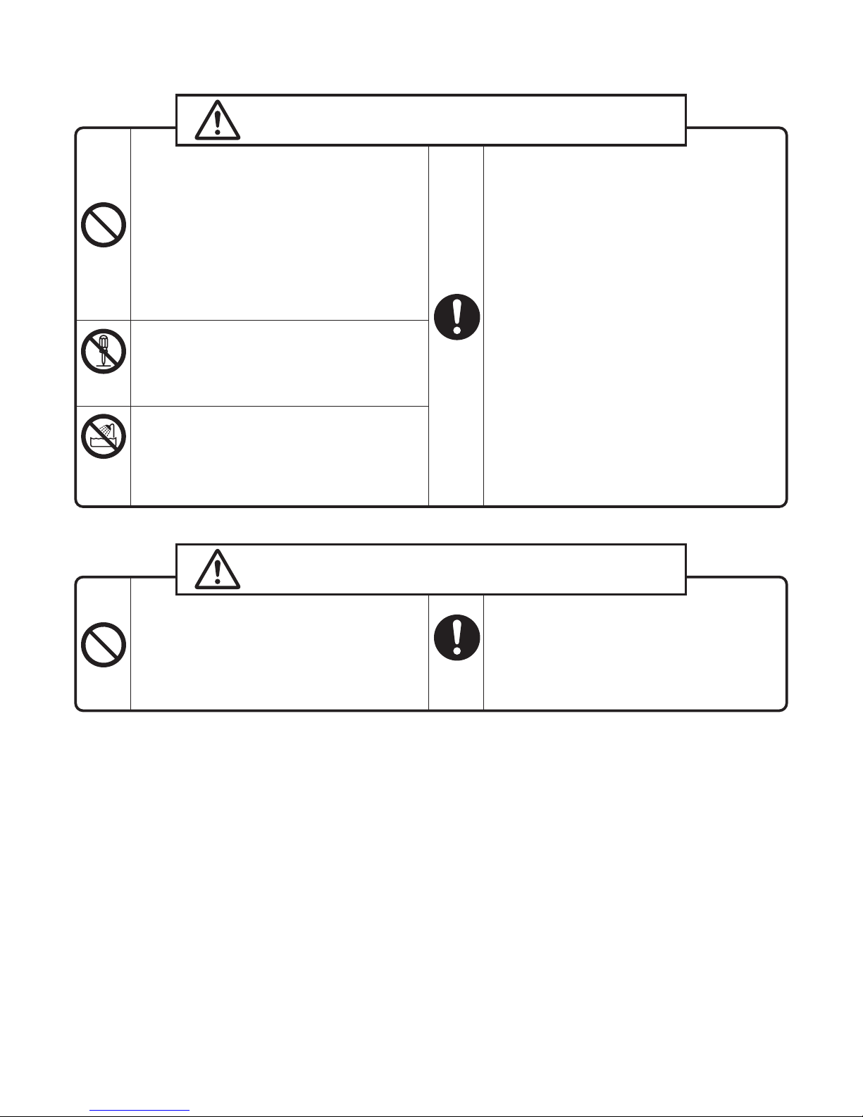
Safety Precautions
Warning
The following may lead to death or serious personal
injury if the unit is handled incorrectly.
Caution
The following may lead to injury or damage to
property if the unit is handled incorrectly.
Prohibited
Prohibited
Do not
disassemble
Do not use in the
bathroom/
shower room
− 3 −
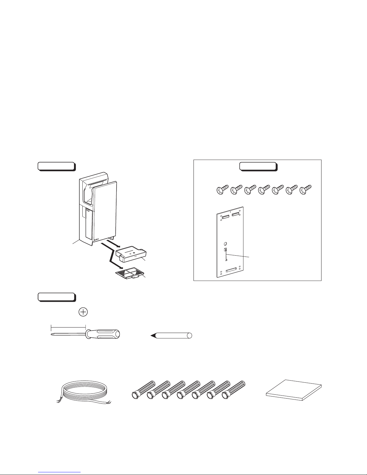
Back panel……… 1
Mounting screws (5 x 30 Type 1 tapping screws)… 7
Product
Required items
Pre-installation checks
■ Checking the installation environment
Do not install in the following types of location.
(This may cause malfunctions.)
Outdoors Locations where the temperature could be lower than 50ºF (10ºC). Locations where there is a lot of
dust. Locations where the temperature could be higher than 104ºF (40ºC). Locations where there is a lot of
condensation. Locations where salt damage may occur. Vehicles (including ships and airplanes)
Locations where the unit is in direct or strong sunlight. (May cause the sensor to malfunction.)
Near food or tableware. Locations where the unit may come into direct contact with water. Kitchens
(Where there is a risk of water splashing.)
Locations where corrosive, neutral, or reductive gases are present.
(This may shorten the working life of the unit and/or cause malfunctions.)
Rooms that have a sterilization basin, swimming pools, bathrooms.
■ Check the unit, accessories, and items required for installation
Main unit
Longer than 6" (150mm)
■ Prepare if required
AWG #12 or #14 solid or
stranded copper wire
※ Not needed if the
internal wiring is
complete
Drain tank
Air fi lter
Green striped
bonding wire
SCREW ANCHOR…7
※ Use on concrete walls
Wall reinforcement
※ Reinforces walls made
of materials other than
concrete
■ Check the heater settings and air speed settings
Check the heater ON/OFF settings and air speed HIGH/STANDARD settings with the customer beforehand.
(The customer cannot adjust the settings after installation is complete.)
Accessories
Pen
To mark position to insert metal
screw plugs in the wall
Screwdriver
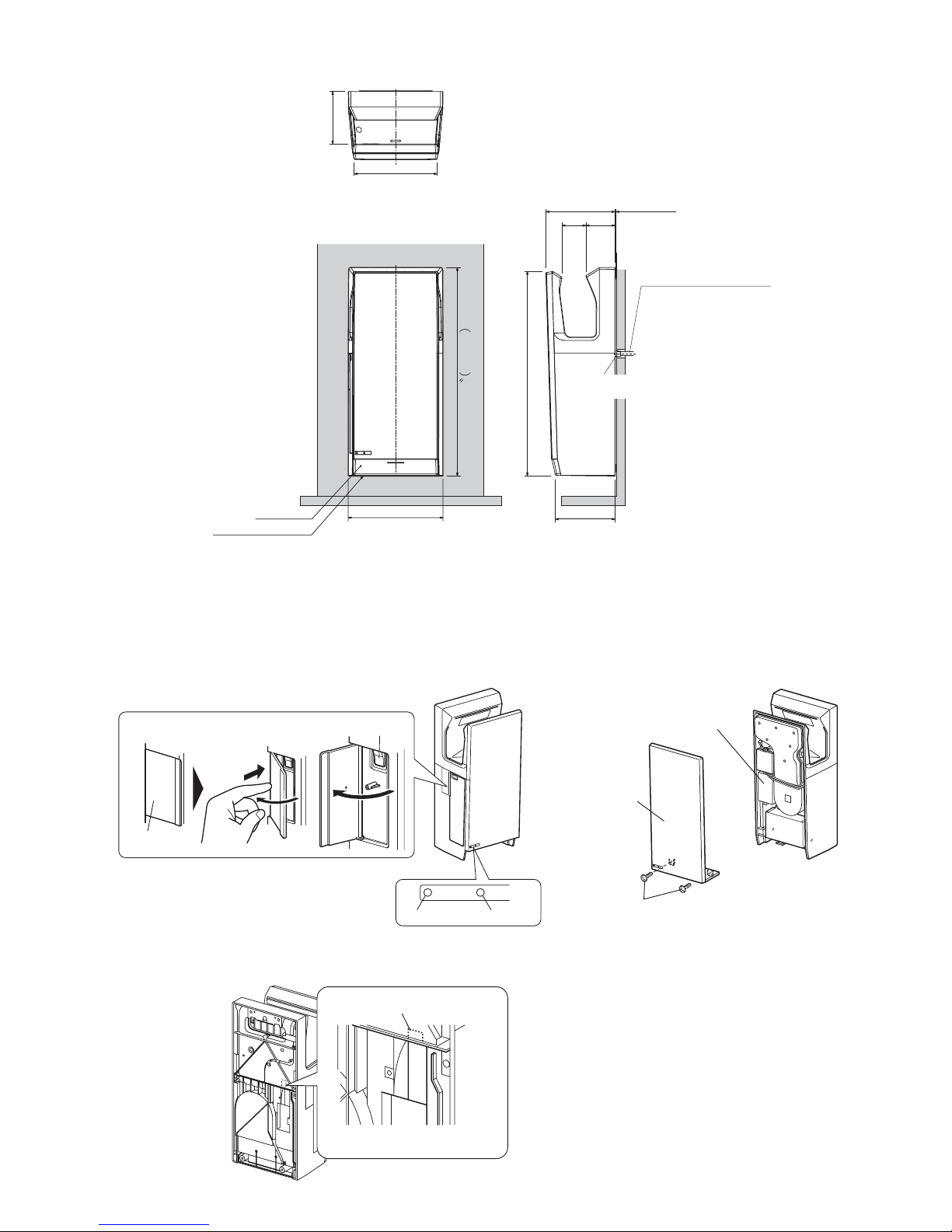
− 4 −
Power Heater
6⁵₈"
(168mm)
Electrical Conduit/Tubing
26³₈
〝︵
670mm
︶
25¹⁵₁₆"(658mm)
Drain tank
Air fi lter (air intake)
※ Maximum width
of main unit
8⁵₈"(219mm)
¹₂"(16mm)
Connector
¹₈"(3mm)
3¹¹₁₆ "
(93mm)
7⁷₁₆"
(189mm)
Maintenance switch
Display
Power lamp
Service panel
Heater lamp
Terminal block
Power cable hole
Names of parts and external dimensions
■ Front
■ Rear
in. (mm)
Front panel
Front panel
mounting screws
10³₈"(263mm)
3¹₁₆"
(77mm)
11¹³ ₁₆ "(300mm※)
Maintenance switch
Refer to the "Installation conditions" on page 5.
 Loading...