

Page 1

General-Purpose AC Servo
SSCNET III/H Interface
Drive Unit Instruction Manual
-MR-J4-DU_B4-RJ100
Page 2

Page 3
SAFETY INSTRUCTIONS
WARNING
Indicates that incorrect handling may cause hazardous conditions, resulting in
death or severe injury.
CAUTION
Indicates that incorrect handling may cause hazardous conditions, resulting in
minor or moderate injury or property damage.
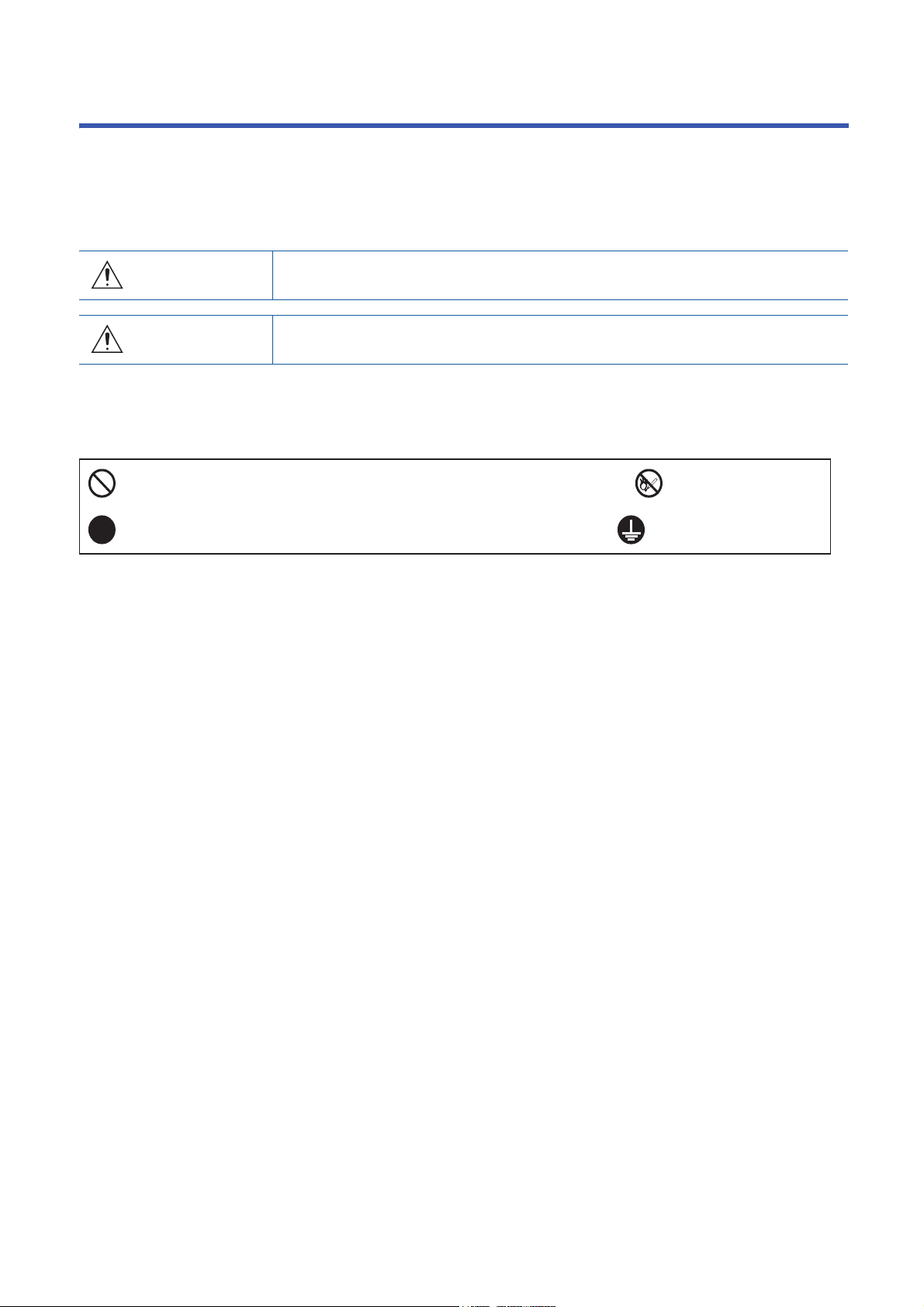
Indicates what must not be done. For example, "No Fire" is indicated by .
Indicates what must be done. For example, grounding is indicated by .
(Please read the instructions carefully before using the equipment.)
To use the equipment correctly, do not attempt to install, operate, maintain, or inspect the equipment until you have read
through this Instruction Manual, Installation guide, and appended documents carefully. Do not use the equipment until you
have a full knowledge of the equipment, safety information and instructions.
In this Instruction Manual, the safety instruction levels are classified into "WARNING" and "CAUTION".
Note that the CAUTION level may lead to a serious consequence depending on conditions.
Please follow the instructions of both levels because they are important to personnel safety.
What must not be done and what must be done are indicated by the following diagrammatic symbols.
In this Instruction Manual, instructions at a lower level than the above, instructions for other functions, and so on are classified
into "POINT".
After reading this Instruction Manual, keep it accessible to the operator.
1
Page 4

[To prevent electric shock, note the following]
WARNING
● Before wiring, turn off the power and wait for 20 minutes or more until the charge lamp turns off. Then,
confirm that the voltage between L+ and L- is safe with a voltage tester or others. Otherwise, an
electric shock may occur. In addition, when confirming whether the charge lamp is off or not, always
confirm it from the front of the converter unit.
● Ground the converter unit, drive unit, and servo motor securely.
● Any person who is involved in wiring and inspection should be fully competent to do the work.
● Do not attempt to wire the converter unit, drive unit, and servo motor until they have been installed.
Otherwise, it may cause an electric shock.
● Do not operate the switches with wet hands. Otherwise, it may cause an electric shock.
● The cables should not be damaged, stressed, loaded, or pinched. Otherwise, it may cause an electric
shock.
● During power-on or operation, do not open the front cover of the converter unit and the drive unit.
Otherwise, it may cause an electric shock.
● Do not operate the converter unit and the drive unit with the front cover removed. High-voltage
terminals and charging area are exposed and you may get an electric shock.
● Except for wiring or periodic inspection, do not remove the front cover of the converter unit and the
drive unit even if the power is off. The converter unit and the drive unit are charged, and you may get
an electric shock.
● To prevent an electric shock, be sure to connect the protective earth (PE) terminal (marked ) of the
converter unit and the drive unit to the protective earth (PE) of the cabinet.
● To avoid an electric shock, insulate the connections of the power supply terminals.
[To prevent fire, note the following]
CAUTION
● Install the converter unit, the drive unit, the servo motor, and the regenerative resistor on
incombustible material. Installing them directly or close to combustibles will lead to smoke or a fire.
● Be sure to connect a magnetic contactor between the power supply and the main circuit power supply
(L1/L2/L3) of the converter unit, in order to configure a circuit that shuts off the power supply by the
magnetic contactor. If the magnetic contactor is not connected, a continuous flow of a large current
may cause smoke or a fire when the converter unit or the drive unit malfunctions.
● Be sure to connect a magnetic contactor for each converter unit between the power supply and the
power supply (L1/L2/L3) of the converter unit, in order to configure a circuit that shuts off the power
supply by the magnetic contactor. If a molded-case circuit breaker or fuse is not connected, a
continuous flow of a large current may cause smoke or a fire when the converter unit malfunctions.
● When using the regenerative resistor, shut the power off with an alarm signal. Otherwise, a
regenerative transistor malfunction or the like may overheat the regenerative resistor, causing smoke
or a fire.
● Provide adequate protection to prevent screws and other conductive matter, oil and other combustible
matter from entering the converter unit, the drive unit, and the servo motor.
2
Page 5

[To prevent injury, note the following]
CAUTION
● Only the power/signal specified in the Instruction Manual should be applied to each terminal.
Otherwise, it may cause an electric shock, fire, injury, etc.
● Connect cables to the correct terminals. Otherwise, a burst, damage, etc., may occur.
● Ensure that polarity (+/-) is correct. Otherwise, a burst, damage, etc., may occur.
● The heat sink of the converter unit and drive unit, the regenerative resistor, the servo motor, etc. may
be hot while power is on and for some time after power-off. Take safety measures such as providing
covers to avoid accidentally touching them by hands and parts such as cables.
[Additional instructions]
The following instructions should also be fully noted. Incorrect handling may cause a malfunction, injury, electric shock, fire,
etc.
3
Page 6
[Transportation and installation]
CAUTION
● Transport the products correctly according to their mass.
● Use the eyebolts of the converter unit and of the drive unit only for transporting. Do not use the
eyebolts for transporting with the converter unit and the drive unit mounted on a machine.
● Do not overtighten the eyebolts of the converter unit and of the drive unit. Tightening too hard may
damage the tap.
● Stacking in excess of the specified number of product packages is not allowed.
● Do not hold the front cover, cables, or connectors when carrying the converter unit and drive unit.
Otherwise, it may drop.
● Install the converter unit, the drive unit, and the servo motor in a load-bearing place in accordance
with the Instruction Manual.
● Do not get on or put heavy load on the equipment. Otherwise, it may cause injury.
● The equipment must be installed in the specified direction.
● Maintain specified clearances between the converter unit/drive unit and the inner surfaces of a control
cabinet or other equipment.
● Do not install or operate the converter unit, the drive unit, and the servo motor which have been
damaged or have any parts missing.
● Do not block the intake and exhaust areas of the converter unit and the drive unit. Otherwise, it may
cause a malfunction.
● Do not drop or apply heavy impact on the converter units, the drive units, and the servo motors.
Otherwise, it may cause injury, malfunction, etc.
● Do not strike the connector. Otherwise, it may cause a connection failure, malfunction, etc.
● When you keep or use the equipment, please fulfill the following environment.
Item Environment
Ambient
temperature
Ambient
humidity
Vibration resistance
Operation
Operation
Ambience
Altitude
Storage
Storage
Indoors (no direct sunlight), free from corrosive gas, flammable gas, oil mist, dust, and dirt
2000 m or less above sea level (Contact your local sales office for the altitude for options.)
● When the equipment has been stored for an extended period of time, contact your local sales office.
● When handling the converter unit and the drive unit, be careful with the sharp edges of the converter
unit and drive unit.
● The converter unit and the drive unit must be installed in a metal cabinet.
● When fumigants that contain halogen materials, such as fluorine, chlorine, bromine, and iodine, are
used for disinfecting and protecting wooden packaging from insects, they cause a malfunction when
entering our products. Please take necessary precautions to ensure that remaining materials from
fumigant do not enter our products, or treat packaging with methods other than fumigation, such as
heat treatment. Additionally, disinfect and protect wood from insects before packing the products.
● To prevent a fire or injury in case of an earthquake or other natural disasters, securely install, mount,
and wire the servo motor in accordance with the Instruction Manual.
0 °C to 55 °C (non-freezing)
-20 °C to 65 °C (non-freezing)
5 %RH to 90 %RH (non-condensing)
2
, at 10 Hz to 55 Hz (X, Y, Z axes)
5.9 m/s
4
Page 7
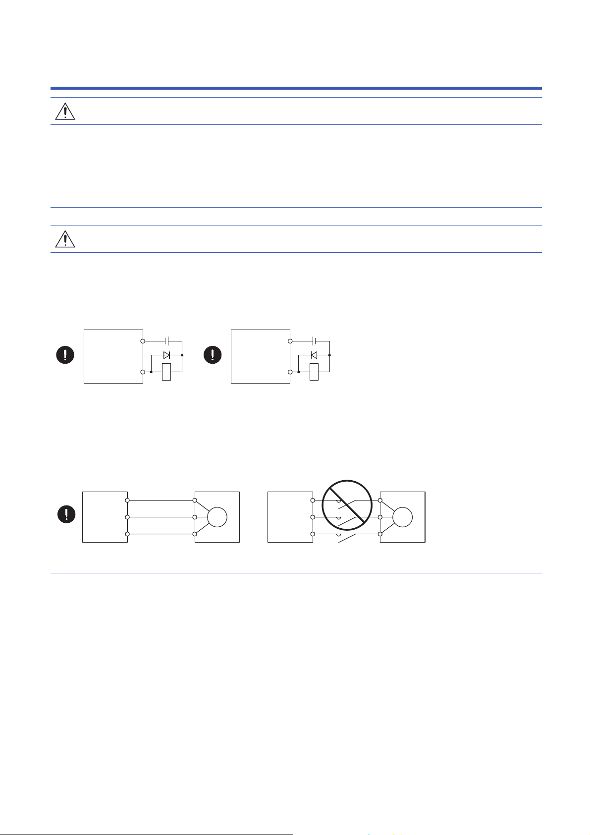
[Wiring]
U
Servo motor
MV
W
U
V
W
Drive unit
U
Servo motor
MV
W
U
V
W
Drive unit
DOCOM
Control
output signal
Control
output signal
24 V DC
Converter unit
Drive unit
RA
For sink output interface
DOCOM
24 V DC
Converter unit
Drive unit
RA
For source output interface
CAUTION
● Wire the equipment correctly and securely. Otherwise, the servo motor may operate unexpectedly.
● Make sure to connect the cables and connectors by using the fixing screws and the locking
mechanism. Otherwise, the cables and connectors may be disconnected during operation.
● Do not install a power capacitor, surge killer, or radio noise filter (optional FR-BIF(-H)) on the drive unit
output side.
● To avoid a malfunction of the servo motor, connect the wires to the correct phase terminals (U/V/W) of
the drive unit and the servo motor.
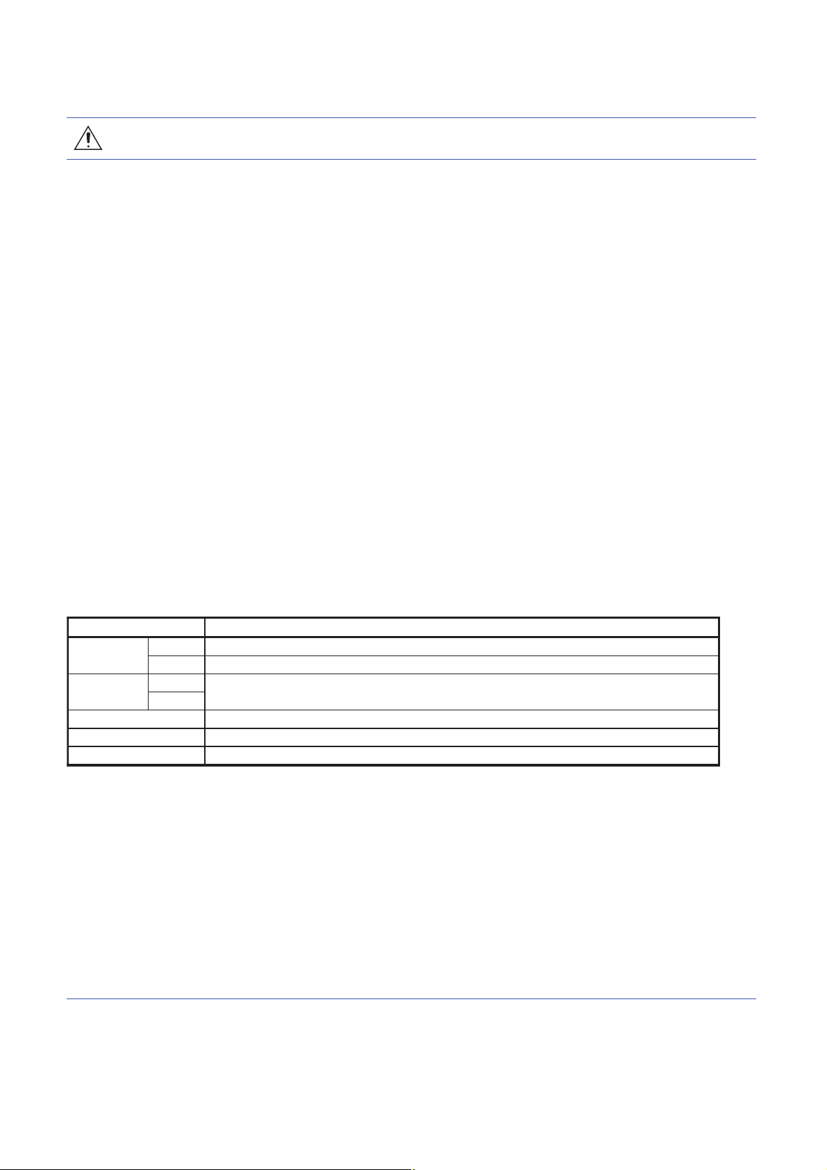
● Connect the drive unit power outputs (U/V/W) to the servo motor power inputs (U/V/W) directly. Do not
connect a magnetic contactor and others between them. Otherwise, it may cause a malfunction.
● The connection diagrams in this Instruction Manual are shown for sink interfaces, unless stated
otherwise.
● Install the surge absorbing diode to the DC relay for control output signals in the converter unit and the
drive unit in the specified direction. Otherwise, the converter unit and the drive unit will malfunction
and will not output signals, disabling the emergency stop and other protective circuits.
● When the wires are not tightened enough to the terminal block, the wires or terminal block may
generate heat because of the poor contact. Be sure to tighten the wires with specified torque.
● Connecting a servo motor of the wrong axis to U, V, W, or CN2 of the drive unit may cause a
malfunction.
● To prevent an unexpected restart of the drive unit, configure a circuit to turn off EM2 or EM1 when the
main circuit power is turned off.
● To prevent malfunction, avoid bundling the power lines (input/output) of the converter unit and the
signal cables together or running them in parallel to each other. Separate the power lines from the
signal cables.
5
Page 8

[Test run and adjustment]
CAUTION
● When executing a test run, follow the notice and procedures in this instruction manual. Otherwise, it
may cause a malfunction, damage to the machine, or injury.
● Before operation, check and adjust the parameter settings. Improper settings may cause some
machines to operate unexpectedly.
● Never make a drastic adjustment or change to the parameter values as doing so will make the
operation unstable.
● Do not get close to moving parts during the servo-on status.
[Usage]
CAUTION
● For equipment in which the moving part of the machine may collide against the load side, install a limit
switch or stopper to the end of the moving part. The machine may be damaged due to a collision.
● Do not disassemble, repair, or modify the product. Otherwise, it may cause an electric shock, fire,
injury, etc. Disassembled, repaired, and/or modified products are not covered under warranty.
● Before resetting an alarm, make sure that the run signal of the drive unit is off to prevent a sudden
restart. Otherwise, it may cause an accident.
● Use a noise filter, etc., to minimize the influence of electromagnetic interference. Electromagnetic
interference may affect the electronic equipment used near the converter unit and the drive unit.
● Do not burn or destroy the converter unit and the drive unit. Doing so may generate a toxic gas.
● Use the converter unit and the drive unit with the specified servo motor.
● Correctly wire options and peripheral equipment, etc. in the correct combination. Otherwise, it may
cause an electric shock, fire, injury, etc.
● The electromagnetic brake on the servo motor is designed to hold the motor shaft and should not be
used for ordinary braking.
● For such reasons as incorrect wiring, service life, and mechanical structure (e.g. where a ball screw
and the servo motor are coupled via a timing belt), the electromagnetic brake may not hold the motor
shaft. To ensure safety, install a stopper on the machine side.
● If the dynamic brake is activated at power-off, alarm occurrence, etc., do not rotate the servo motor by
an external force. Otherwise, it may cause a fire.
6
Page 9
[Corrective actions]
Servo motor
Electromagnetic brake
B
U
RA
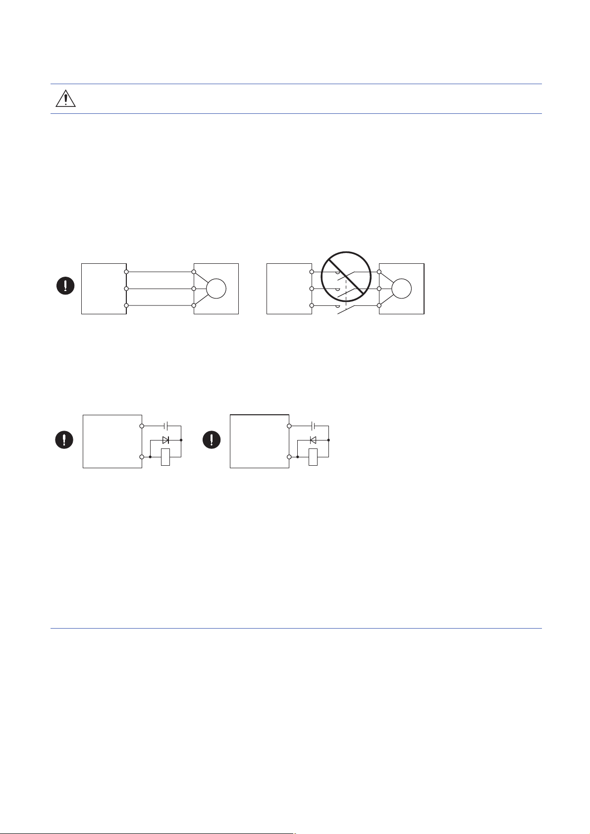
Contacts must be opened with
the emergency stop switch.
Contacts must be opened when ALM
(Malfunction) or MBR (Electromagnetic
brake interlock) turns off.
24 V DC
CAUTION
● Ensure safety by confirming the power off, etc. before performing corrective actions. Otherwise, it may
cause an accident.
● If it is assumed that a power failure, machine stoppage, or product malfunction may result in a
hazardous situation, use a servo motor with an electromagnetic brake or provide an external brake
system for holding purpose to prevent such hazard.
● Configure an electromagnetic brake circuit which is interlocked with an external emergency stop
switch.
● When an alarm occurs, eliminate its cause, ensure safety, and deactivate the alarm to restart
operation.
● If the molded-case circuit breaker or fuse is activated, be sure to remove the cause and secure safety
before switching the power on. If necessary, replace the converter unit and drive unit, and recheck the
wiring. Otherwise, it may cause smoke, fire, or an electric shock.
● Provide an adequate protection to prevent unexpected restart after an instantaneous power failure.
● To prevent an electric shock, injury, or fire from occurring after an earthquake or other natural
disasters, ensure safety by checking conditions, such as the installation, mounting, wiring, and
equipment before switching the power on.
[Maintenance, inspection and parts replacement]
CAUTION
● Make sure that the emergency stop circuit operates properly such that an operation can be stopped
immediately and a power is shut off by the emergency stop switch.
● It is recommended that the converter unit and the drive unit be replaced every 10 years when it is
used in general environment.
● When using a converter unit or a drive unit whose power has not been turned on for a long time,
contact your local sales office.
[General instruction]
● To illustrate details, the equipment in the diagrams of this Instruction Manual may have been drawn
without covers and safety guards. When the equipment is operated, the covers and safety guards
must be installed as specified. Operation must be performed in accordance with this Instruction
Manual.
7
Page 10

DISPOSAL OF WASTE
• Please dispose a servo amplifier, battery (primary battery) and other options according to your local laws and regulations.
EEP-ROM LIFE
The number of write times to the EEP-ROM, which stores parameter settings, etc., is limited to 100,000. If the total number of
the following operations exceeds 100,000, the converter unit and the drive unit may malfunction when the EEP-ROM reaches
the end of its useful life.
• Write to the EEP-ROM due to parameter setting changes
• Write to the EEP-ROM due to device changes
STO FUNCTION OF THE DRIVE UNIT
When using the STO function of the drive unit, refer to chapter 13 of “MR-J4-_A_(-RJ) Servo Amplifier Instruction Manual".
For the MR-J3-D05 safety logic unit, refer to app. 5 of “MR-J4-_B_(-RJ) Servo Amplifier Instruction Manual".
COMPLIANCE WITH GLOBAL STANDARDS
For compliance with global standards, refer to "MR-CV_/MR-CR55K_/MR-J4-DU_(-RJ) Instruction Manual".
8
Page 11

ABOUT THE MANUALS
You must have this Instruction Manual and the following manuals to use this servo. Be sure to prepare all the instruction
manuals necessary to use the servo safely.
Relevant manuals
Manual name Manual No.
MELSERVO MR-J4-_B(-RJ) Servo Amplifier Instruction Manual SH(NA)030098
MELSERVO MR-CV_/MR-CR55K_/MR-J4-DU_(-RJ) Instruction Manual SH(NA)030145
MELSERVO-J4 Servo amplifier Instruction Manual (Troubleshooting) SH(NA)030108
MELSERVO MR-D30 Instruction Manual
MELSERVO Servo Motor Instruction Manual (Vol. 3) SH(NA)030099
EMC Installation Guidelines IB(NA)67310
*1 It is necessary for using an MR-D30 functional safety unit.
*1
This Instruction Manual does not describe the following items. Refer to the section of the detailed explanation field for details.
"MR-J4-_B_" means "MR-J4-_B_(-RJ) Servo Amplifier Instruction Manual". "MR-J4-DU_B_" means "MR-CV_/MR-CR55K_/
MR-J4-DU_(-RJ) Instruction Manual".
Item Detailed explanation
Normal gain adjustment
Special adjustment functions
Dimensions MR-J4-DU_B_ chapter 7
Absolute position detection system
*1
*2
*3
SH(NA)030131
MR-J4-_B_ chapter 6
MR-J4-_B_ chapter 7
MR-J4-_B_ chapter 12
*1 For parallel drive systems, the one-touch tuning is unavailable.
*2 A combination of the MR-CV55K4_ power regeneration converter unit and drive unit does not comply with SEMI-F47 standard. For the
advanced vibration suppression control II and the adaptive filter II, "Automatic setting” is invalid. Only "Manual setting" is valid.
*3 For absolute position detection systems, connect an optional battery to only the drive unit of the encoder master servo amplifier. Do not
connect the optional battery to the drive units of the encoder slave servo amplifiers.
CABLES USED FOR WIRING
Wires mentioned in this Instruction Manual are selected based on the ambient temperature of 40 .
U.S. CUSTOMARY UNITS
U.S. customary units are not shown in this manual. Convert the values if necessary according to the following table.
Quantity SI (metric) unit U.S. customary unit
Mass 1 [kg] 2.2046 [lb]
Length 1 [mm] 0.03937 [inch]
Torque 1 [N.m] 141.6 [oz.inch]
-4
Moment of inertia 1 [(× 10
Load (thrust load/axial load) 1 [N] 0.2248 [lbf]
Temperature N [] × 9/5 + 32 N []
kg.m2)] 5.4675 [oz.inch2]
9
Page 12

CONTENTS
SAFETY INSTRUCTIONS. . . . . . . . . . . . . . . . . . . . . . . . . . . . . . . . . . . . . . . . . . . . . . . . . . . . . . . . . . . . . . . . . . . .1
DISPOSAL OF WASTE . . . . . . . . . . . . . . . . . . . . . . . . . . . . . . . . . . . . . . . . . . . . . . . . . . . . . . . . . . . . . . . . . . . . . .8
EEP-ROM LIFE . . . . . . . . . . . . . . . . . . . . . . . . . . . . . . . . . . . . . . . . . . . . . . . . . . . . . . . . . . . . . . . . . . . . . . . . . . . .8
STO FUNCTION OF THE DRIVE UNIT . . . . . . . . . . . . . . . . . . . . . . . . . . . . . . . . . . . . . . . . . . . . . . . . . . . . . . . . .8
COMPLIANCE WITH GLOBAL STANDARDS . . . . . . . . . . . . . . . . . . . . . . . . . . . . . . . . . . . . . . . . . . . . . . . . . . . .8
ABOUT THE MANUALS . . . . . . . . . . . . . . . . . . . . . . . . . . . . . . . . . . . . . . . . . . . . . . . . . . . . . . . . . . . . . . . . . . . . .9
CABLES USED FOR WIRING . . . . . . . . . . . . . . . . . . . . . . . . . . . . . . . . . . . . . . . . . . . . . . . . . . . . . . . . . . . . . . . .9
U.S. CUSTOMARY UNITS . . . . . . . . . . . . . . . . . . . . . . . . . . . . . . . . . . . . . . . . . . . . . . . . . . . . . . . . . . . . . . . . . . .9
CHAPTER 1 FUNCTIONS AND CONFIGURATION 12
1.1 Description. . . . . . . . . . . . . . . . . . . . . . . . . . . . . . . . . . . . . . . . . . . . . . . . . . . . . . . . . . . . . . . . . . . . . . . . . . . . . 12
1.2 Model designation . . . . . . . . . . . . . . . . . . . . . . . . . . . . . . . . . . . . . . . . . . . . . . . . . . . . . . . . . . . . . . . . . . . . . . .13
1.3 Combinations of power regeneration converter units, drive units, and servo motors . . . . . . . . . . . . . . . 13
1.4 Compatible controller . . . . . . . . . . . . . . . . . . . . . . . . . . . . . . . . . . . . . . . . . . . . . . . . . . . . . . . . . . . . . . . . . . . . 14
1.5 Function list . . . . . . . . . . . . . . . . . . . . . . . . . . . . . . . . . . . . . . . . . . . . . . . . . . . . . . . . . . . . . . . . . . . . . . . . . . . . 14
1.6 Configuration including peripheral equipment . . . . . . . . . . . . . . . . . . . . . . . . . . . . . . . . . . . . . . . . . . . . . . . 15
CHAPTER 2 INSTALLATION 16
2.1 Installation direction and clearances . . . . . . . . . . . . . . . . . . . . . . . . . . . . . . . . . . . . . . . . . . . . . . . . . . . . . . . 17
CHAPTER 3 SIGNALS AND WIRING 20
3.1 Connection example of power circuit . . . . . . . . . . . . . . . . . . . . . . . . . . . . . . . . . . . . . . . . . . . . . . . . . . . . . . .21
3.2 Alarm occurrence timing chart . . . . . . . . . . . . . . . . . . . . . . . . . . . . . . . . . . . . . . . . . . . . . . . . . . . . . . . . . . . . 26
When you use the forced stop deceleration function. . . . . . . . . . . . . . . . . . . . . . . . . . . . . . . . . . . . . . . . . . . . . . 27
When you do not use the forced stop deceleration function . . . . . . . . . . . . . . . . . . . . . . . . . . . . . . . . . . . . . . . . 30
3.3 Grounding . . . . . . . . . . . . . . . . . . . . . . . . . . . . . . . . . . . . . . . . . . . . . . . . . . . . . . . . . . . . . . . . . . . . . . . . . . . . . 31
CHAPTER 4 STARTUP 32
4.1 Switching power on for the first time . . . . . . . . . . . . . . . . . . . . . . . . . . . . . . . . . . . . . . . . . . . . . . . . . . . . . . .33
4.2 Startup . . . . . . . . . . . . . . . . . . . . . . . . . . . . . . . . . . . . . . . . . . . . . . . . . . . . . . . . . . . . . . . . . . . . . . . . . . . . . . . .34
CHAPTER 5 PARAMETERS 35
CHAPTER 6 TROUBLESHOOTING 41
6.1 Troubleshooting for MR-CV_ power regeneration converter unit . . . . . . . . . . . . . . . . . . . . . . . . . . . . . . . .41
Explanation for the lists . . . . . . . . . . . . . . . . . . . . . . . . . . . . . . . . . . . . . . . . . . . . . . . . . . . . . . . . . . . . . . . . . . . . 41
Alarm list . . . . . . . . . . . . . . . . . . . . . . . . . . . . . . . . . . . . . . . . . . . . . . . . . . . . . . . . . . . . . . . . . . . . . . . . . . . . . . . 42
Warning list . . . . . . . . . . . . . . . . . . . . . . . . . . . . . . . . . . . . . . . . . . . . . . . . . . . . . . . . . . . . . . . . . . . . . . . . . . . . . 42
6.2 Troubleshooting for drive unit . . . . . . . . . . . . . . . . . . . . . . . . . . . . . . . . . . . . . . . . . . . . . . . . . . . . . . . . . . . . . 43
Explanation for the lists . . . . . . . . . . . . . . . . . . . . . . . . . . . . . . . . . . . . . . . . . . . . . . . . . . . . . . . . . . . . . . . . . . . . 43
Alarm list . . . . . . . . . . . . . . . . . . . . . . . . . . . . . . . . . . . . . . . . . . . . . . . . . . . . . . . . . . . . . . . . . . . . . . . . . . . . . . . 44
Warning list . . . . . . . . . . . . . . . . . . . . . . . . . . . . . . . . . . . . . . . . . . . . . . . . . . . . . . . . . . . . . . . . . . . . . . . . . . . . . 53
10
CHAPTER 7 CHARACTERISTICS 55
7.1 Overload protection characteristics . . . . . . . . . . . . . . . . . . . . . . . . . . . . . . . . . . . . . . . . . . . . . . . . . . . . . . . . 55
7.2 Power supply capacity and generated loss . . . . . . . . . . . . . . . . . . . . . . . . . . . . . . . . . . . . . . . . . . . . . . . . . . 56
7.3 Dynamic brake characteristics. . . . . . . . . . . . . . . . . . . . . . . . . . . . . . . . . . . . . . . . . . . . . . . . . . . . . . . . . . . . . 58
7.4 Inrush currents at power-on of main circuit/control circuit . . . . . . . . . . . . . . . . . . . . . . . . . . . . . . . . . . . . . 60
Page 13

Inrush currents of the power regeneration converter. . . . . . . . . . . . . . . . . . . . . . . . . . . . . . . . . . . . . . . . . . . . . . 60
Inrush current of the drive unit. . . . . . . . . . . . . . . . . . . . . . . . . . . . . . . . . . . . . . . . . . . . . . . . . . . . . . . . . . . . . . . 60
CHAPTER 8 OPTIONS AND PERIPHERAL EQUIPMENT 61
8.1 MR Configurator2 . . . . . . . . . . . . . . . . . . . . . . . . . . . . . . . . . . . . . . . . . . . . . . . . . . . . . . . . . . . . . . . . . . . . . . . 62
Restrictions . . . . . . . . . . . . . . . . . . . . . . . . . . . . . . . . . . . . . . . . . . . . . . . . . . . . . . . . . . . . . . . . . . . . . . . . . . . . . 62
Using the parallel drive system . . . . . . . . . . . . . . . . . . . . . . . . . . . . . . . . . . . . . . . . . . . . . . . . . . . . . . . . . . . . . . 62
How to select the model name of the servo amplifier registered. . . . . . . . . . . . . . . . . . . . . . . . . . . . . . . . . . . . . 66
8.2 AC reactor . . . . . . . . . . . . . . . . . . . . . . . . . . . . . . . . . . . . . . . . . . . . . . . . . . . . . . . . . . . . . . . . . . . . . . . . . . . . . 67
8.3 External dynamic brake . . . . . . . . . . . . . . . . . . . . . . . . . . . . . . . . . . . . . . . . . . . . . . . . . . . . . . . . . . . . . . . . . . 69
CHAPTER 9 USING STO FUNCTION 72
CHAPTER 10 APPLICATION OF FUNCTIONS 74
10.1 Compatible with MR-D30 functional safety unit . . . . . . . . . . . . . . . . . . . . . . . . . . . . . . . . . . . . . . . . . . . . . . . 74
Description. . . . . . . . . . . . . . . . . . . . . . . . . . . . . . . . . . . . . . . . . . . . . . . . . . . . . . . . . . . . . . . . . . . . . . . . . . . . . . 74
Connection diagram . . . . . . . . . . . . . . . . . . . . . . . . . . . . . . . . . . . . . . . . . . . . . . . . . . . . . . . . . . . . . . . . . . . . . . 76
CHAPTER 11 APPENDIX 78
11.1 Analog monitor . . . . . . . . . . . . . . . . . . . . . . . . . . . . . . . . . . . . . . . . . . . . . . . . . . . . . . . . . . . . . . . . . . . . . . . . .78
REVISIONS. . . . . . . . . . . . . . . . . . . . . . . . . . . . . . . . . . . . . . . . . . . . . . . . . . . . . . . . . . . . . . . . . . . . . . . . . . . . . .80
WARRANTY . . . . . . . . . . . . . . . . . . . . . . . . . . . . . . . . . . . . . . . . . . . . . . . . . . . . . . . . . . . . . . . . . . . . . . . . . . . . .81
TRADEMARKS . . . . . . . . . . . . . . . . . . . . . . . . . . . . . . . . . . . . . . . . . . . . . . . . . . . . . . . . . . . . . . . . . . . . . . . . . . .82
CONTENTS
11
Page 14
1 FUNCTIONS AND CONFIGURATION
The following items are the same as those for MR-J4-_B_(-RJ). Refer to the section of the detailed explanation field for
details. "MR-J4-DU_B_" means "MR-CV_/MR-CR55K_/MR-J4-DU_(-RJ) Instruction Manual".
Item Detailed explanation
Function block diagram MR-J4-DU_B_ section 3.1
Standard specifications MR-J4-DU_B_ section 1.4
Structure
*1 Do not connect an external encoder to the CN2L connector of the MR-J4-DU_B4-RJ100 drive unit.
1.1 Description
This Instruction Manual describes MR-J4-DU_B4-RJ100 drive units and MR-CV55K4_ power regeneration converter units
compatible with parallel drive systems.
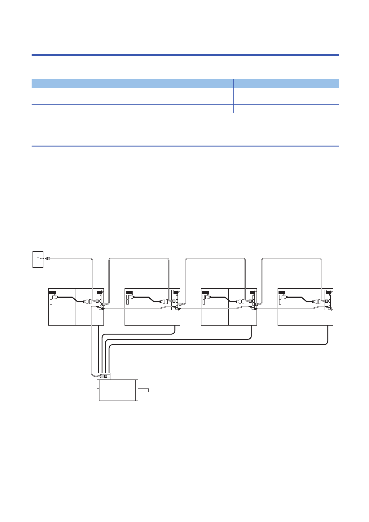
Parallel drive systems drive a servo motor with multiple MR-J4-DU_B4-RJ100 drive units and MR-CV55K4_ power
regeneration converter units connected. The encoder cables are wired by the daisy chain method. Delivering the encoder
information to all servo amplifiers, from encoder master servo amplifiers to encoder slave servo amplifiers, ensures reduced
wiring. A encoder distribution unit is not required.
The following shows a system that drives a servo motor with four MR-J4-DU_B4-RJ100 drive units and four MR-CV55K4_
power regeneration converter units connected. For the number of drive units required to be connected to one servo motor,
refer to the following.
Page 13 Combinations of power regeneration converter units, drive units, and servo motors
*1
MR-J4-DU_B_ sections 3.2 and 5.1
Servo system
controller
SSCNET III/H
Encoder master servo amplifier
Power
regeneration
converter unit 1
Drive
unit 1
Power
regeneration
converter unit 2
Servo motor
Drive
unit 2
Power
regeneration
converter unit 3
Drive
unit 3
Encoder slave servo amplifier 3Encoder slave servo amplifier 2Encoder slave servo amplifier 1
Power
regeneration
converter unit 4
Drive
unit 4
12
1 FUNCTIONS AND CONFIGURATION
1.1 Description
Page 15
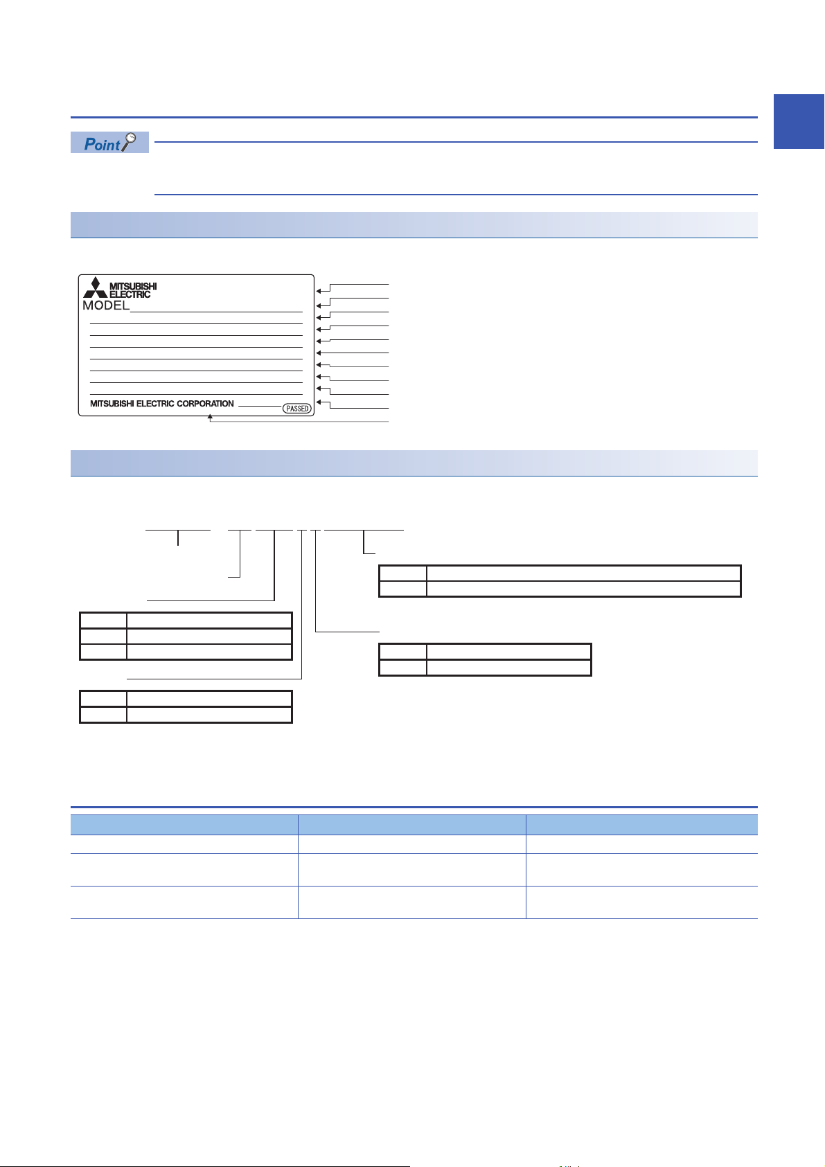
1.2 Model designation
Serial number
Model
Capacity
Applicable power supply
Rated output current
Standard, Manual number
Ambient temperature
IP rating
KC certification number
The year and month of manufacture
Country of origin
TOKYO 100-8310, JAPAN MADE IN JAPAN
DATE:
2017-12
MR-J4-DU55KB4-RJ100
SER. A7Z001001
AC SERVO
POWER
INPUT
OUTPUT
STD.: IEC/EN 61800-5-1 MAN.: IB(NA)0300228
Max. Surrounding Air Temp.: 55°C
IP20 (Terminal block IP00)
: 55kW
: DC513-648V 113.7A
: 3PH323V 0-360Hz 143.0A
MSIP-REI-MEK-TC301A013G52 BC343U843
This section describes MR-J4-DU_B4-RJ100 drive units only. For MR-CV55K4_power regeneration converter
units, refer to section 1.2 in "MR-CV_/MR-CR55K_/MR-J4-DU_(-RJ) Instruction Manual".
Rating plate
The following shows an example of the rating plate for explanation of each item.
Model
The following describes what each block of a model name indicates. Not all combinations of the symbols are available.
1
-MR - J 4 DU KB 4 - R J 15500
Series
Indicates drive unit
Rated output
Symbol Rated output [kW]
45K
55K
Interface
Symbol Interface
SSCNET III/H
B
45
55
Special specifications
Symbol Special specifications
-RJ100
Power supply
Symbol Power supply
Compatible with parallel drive system
3-phase 380 V AC to 480 V AC
4
1.3 Combinations of power regeneration converter
units, drive units, and servo motors
Power regeneration converter unit Drive unit Rotary servo motor
Two units of MR-CV55K4 Two units of MR-J4-DU55KB4-RJ100 HG-JR110K24W0C
Four units of MR-CV55K4 Four units of MR-J4-DU45KB4-RJ100 HG-JR150K24W0C
HG-JR180K24W0C
Four units of MR-CV55K4 Four units of MR-J4-DU55KB4-RJ100 HG-JR200K24W0C
HG-JR220K24W0C
1 FUNCTIONS AND CONFIGURATION
1.2 Model designation
13
Page 16

1.4 Compatible controller
Motion controller Operating system Remark
Q173DSCPU SW8DNC-SV22S87QJ Special operating system
Q172DSCPU SW8DNC-SV22S87QL Special operating system
*1
*1
*1 Motion controllers with a special operating system can be used. Motion controllers with a standard operating system cannot drive
ultrahigh capacity servo motors. For details, contact your local sales office.
1.5 Function list
For the drive unit functions not mentioned in this section, refer to section 1.5 in "MR-J4-_B_(-RJ) Servo Amplifier Instruction
Manual".
Function Description Detailed explanation
Advanced vibration
suppression control II
Adaptive filter II For parallel drive systems, "Automatic setting" is invalid. Only "Manual setting" is valid.
Scale measurement function For parallel drive systems, the scale measurement function is unavailable.
J3 compatibility mode For parallel drive systems, the J3 compatibility mode is unavailable.
Machine analyzer function For parallel drive systems, the machine analyzer function is unavailable.
Test operation mode For parallel drive systems, the test operation mode is unavailable.
Linear servo system For parallel drive systems, the linear servo system is unavailable.
Direct drive servo system For parallel drive systems, the direct drive servo system is unavailable.
Fully closed loop system For parallel drive systems, the fully closed loop system is unavailable.
One-touch tuning For parallel drive systems, the one-touch tuning is unavailable.
SEMI-F47 function A combination of the MR-CV55K4_ power regeneration converter unit and drive unit does not
Tough drive function The tough drive function includes two types: the vibration tough drive and the instantaneous
STO function This function is a functional safety that complies with IEC/EN 61800-5-2. You can create a
Power monitoring function When checking the power in the parallel drive system, use the servo system controller. This
MR-D30 functional safety unit By using MR-D30 together, the safety observation function can be expanded. STO, SS1, SS2,
MR-J3-D05 safety logic unit For parallel drive systems, the MR-J3-D05 safety logic unit is unavailable.
MR-CR_ resistance
regeneration converter unit
For parallel drive systems, "Automatic setting" is invalid. Only "Manual setting" is valid.
This function suppresses vibration and residual vibration at an arm end.
The servo amplifier detects mechanical resonance and sets filter characteristics automatically
to suppress mechanical vibration.
comply with SEMI-F47 standard.
power failure tough drive. For parallel drive systems, only the vibration tough drive is available.
This function makes the equipment continue operating even under the condition that an alarm
occurs.
safety system for the equipment easily.
function calculates the power running energy and the regenerative power from the data in the
servo amplifier such as speed and current. In the SSCNET III/H system, the data are sent to a
servo system controller for analyzing and displaying the power consumption on a display.
SOS, SLS, SSM, and SBC can be used.
For parallel drive systems, the MR-CR_ resistance regeneration converter unit is unavailable.
Page 35 PARAMETERS
Page 35 PARAMETERS
Page 35 PARAMETERS
Page 35 PARAMETERS
Page 72 USING STO
FUNCTION
Page 74 APPLICATION
OF FUNCTIONS
14
1 FUNCTIONS AND CONFIGURATION
1.4 Compatible controller
Page 17
1.6 Configuration including peripheral equipment
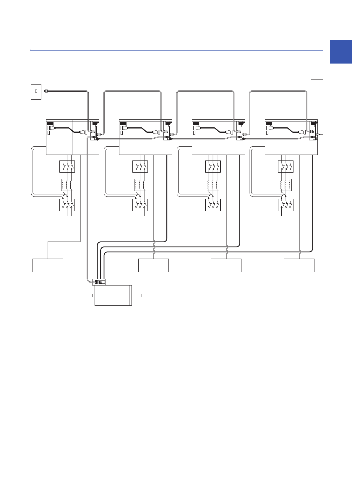
The diagram shows a system that drives a servo motor with four MR-J4-DU_B4-RJ100 drive units and four MR-CV55K4_
power regeneration converter units connected.
1
Servo system
*8
controller
SSCNET III/H
Encoder slave
servo amplifier 1
Magnetic
contactor
(MC)
AC reactor
(MR-AL-55K4-L)
Molded-case
circuit breaker
(MCCB)
Drive
unit 1
*2, *5
*3
Encoder master servo amplifier
Power
regeneration
converter unit 1
*7 *7 *7 *7
Magnetic
contactor
(MC)
AC reactor
(MR-AL-55K4-L)
*6
Molded-case
circuit breaker
(MCCB)
Power supply
3-phase
380 V AC to
480 V AC
*3
Power
regeneration
converter unit 2
*4 *4 *4
*6
Power supply
3-phase
380 V AC to
480 V AC
Drive
unit 2
*2, *5
Encoder slave
servo amplifier 2
Power
regeneration
converter unit 3
Magnetic
contactor
(MC)
AC reactor
(MR-AL-55K4-L)
*6
Molded-case
circuit breaker
(MCCB)
Power supply
3-phase
380 V AC to
480 V AC
*3
Drive
unit 3
*2, *5
Encoder slave
servo amplifier 3
Power
regeneration
converter unit 4
Magnetic
contactor
(MC)
AC reactor
(MR-AL-55K4-L)
*6
Molded-case
circuit breaker
(MCCB)
Power supply
3-phase
380 V AC to
480 V AC
Fit a cap
(standard accessory)
on the unused connector.
*3
Drive
unit 4
*2, *5
Dynamic brake
(DBU-P55K-4-B)
*1
Servo motor
Dynamic brake
(DBU-P55K-4-B)
Dynamic brake
(DBU-P55K-4-B)
Dynamic brake
(DBU-P55K-4-B)
*1 Connect the grounding wire of the servo motor to only the first drive unit. If the grounding wire of the servo motor is connected to two or
more drive units, the circulating current may pass through the grounding wire depending on wiring conditions. When connecting
grounding wires to two or more drive units, be sure to twist the wires of the drive unit power outputs (U/V/W) for safety reasons.
*2 For the power supply, one molded-case circuit breaker, one AC reactor (MR-AL-55K4-L), and one magnetic contactor are required for
each power regeneration converter unit.
*3 Since the system is connected via SSCNET III/H, use a servo amplifier near the Motion controller as an encoder master servo amplifier,
and use the remaining servo amplifiers as encoder slave servo amplifiers. Connect the encoder master servo amplifier and slave servo
amplifiers in series to the same SSCNET III/H system.
*4 The encoder cables between drive units should be within 5 m.
*5 Supply power to all the servo amplifiers (power regeneration converter units and drive units) from the same power source. If power is
supplied from different power sources, a difference may be generated between outputs of the encoder master servo amplifier and
encoder slave servo amplifiers. This may cause the servo motor to operate unpredictably.
*6 Even if an AC reactor is installed on the power regeneration converter unit, the functions operate normally.
*7 Switch on the control circuit power supplies of all the servo amplifiers (power regeneration converter units and drive units)
simultaneously.
*8 Stop all the drive units with the emergency stop of the controller if an alarm occurs.
1 FUNCTIONS AND CONFIGURATION
1.6 Configuration including peripheral equipment
15
Page 18

2 INSTALLATION
WARNING
• To prevent electric shock, ground each equipment securely.
CAUTION
• Stacking in excess of the specified number of product packages is not allowed.
• Do not hold the front cover, cables, or connectors when carrying the converter unit and drive unit. Otherwise, it may drop.
• Install the equipment on incombustible material. Installing them directly or close to combustibles will lead to a fire.
• Install the converter unit, the drive unit, and the servo motor in a load-bearing place in accordance with the Instruction Manual.
• Do not get on or put heavy load on the equipment. Otherwise, it may cause injury.
• Use the equipment within the specified environment. For the environment, refer to section 1.4 in "MR-CV_/MR-CR55K_/MR-J4-DU_(-RJ) Instruction
Manual".
• Provide adequate protection to prevent screws and other conductive matter, oil and other combustible matter from entering the converter unit and the drive
unit.
• Do not block the intake and exhaust areas of the converter unit and the drive unit. Otherwise, it may cause a malfunction.
• Do not drop or apply heavy impact on the converter units, the drive units, and the servo motors. Otherwise, it may cause injury, malfunction, etc.
• Do not install or operate the converter unit and the drive unit which have been damaged or have any parts missing.
• When the equipment has been stored for an extended period of time, contact your local sales office.
• When handling the converter unit and the drive unit, be careful with the sharp edges of the converter unit and drive unit.
• The converter unit and the drive unit must be installed in a metal cabinet.
• When fumigants that contain halogen materials, such as fluorine, chlorine, bromine, and iodine, are used for disinfecting and protecting wooden packaging
from insects, they cause a malfunction when entering our products. Please take necessary precautions to ensure that remaining materials from fumigant do
not enter our products, or treat packaging with methods other than fumigation, such as heat treatment. Additionally, disinfect and protect wood from insects
before packing the products.
The following items are the same as those for MR-J4-_B_(-RJ). Refer to the section of the detailed explanation field for
details. "MR-J4-_B_" means "MR-J4-_B_(-RJ) Servo Amplifier Instruction Manual". "MR-J4-DU_B_" means "MR-CV_/MR-
CR55K_/MR-J4-DU_(-RJ) Instruction Manual".
Item Detailed explanation
Keeping out of foreign materials MR-J4-DU_B_ section 2.2
Encoder cable stress MR-J4-_B_ section 2.3
SSCNET III cable laying MR-J4-_B_ section 2.4
Inspection items MR-J4-DU_B_ section 2.3
Parts having service life MR-J4-DU_B_ section 2.4
Restrictions when using this product at altitude exceeding 1000 m and up to 2000 m above sea level MR-J4-DU_B_ section 2.5
16
2 INSTALLATION
Page 19
2.1 Installation direction and clearances
Cooling
fan
exhaust
80 mm
or more
SideFront
100 mm
or more
120 mm
or more
*1
Drive unitConverter unit Drive unitConverter unit
30 mm
Top
Bottom
CAUTION
• The equipment must be installed in the specified direction. Otherwise, it may cause a malfunction.
• Maintain specified clearances between the converter unit/drive unit and the inner surfaces of a control cabinet or other equipment. Otherwise, it may cause a
malfunction.
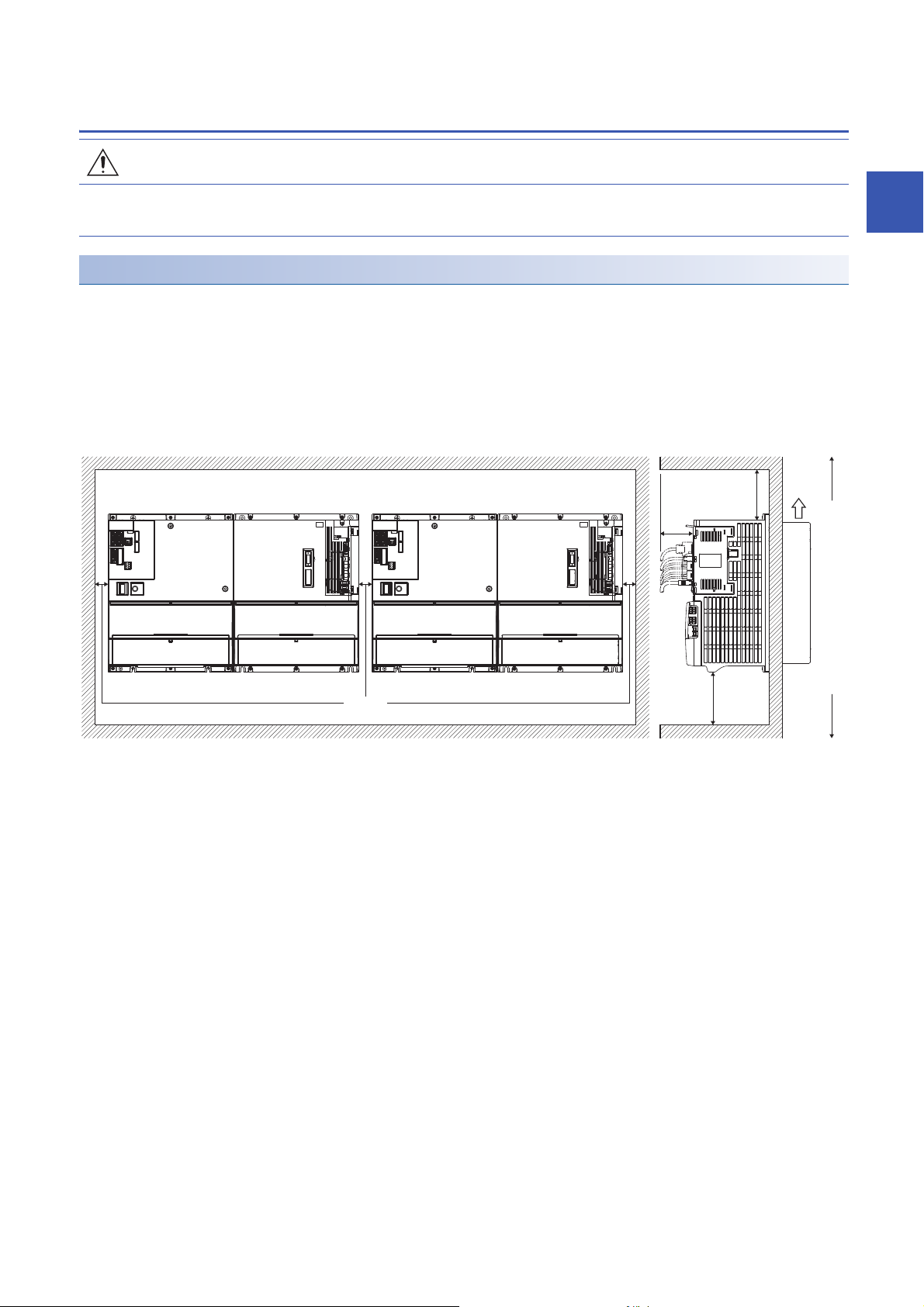
Installation
Make sure to connect a drive unit to the right side of a power regeneration converter unit. Since the units require a cooling
mechanism outside the cabinet, an opening must be provided in each mounting surface as shown below.
The TE2-1 terminal block of the drive unit and the TE2 terminal block of the power regeneration converter unit are connected
using a bus bar. Thus, remove the supplied cover on the right side of the power regeneration converter unit.
■Clearance between sets of combined power regeneration converter units and drive units
mounted side by side
2
*1 A clearance of at least 120 mm is required. Leave a clearance, taking into consideration the flexibility of the cable.
2.1 Installation direction and clearances
2 INSTALLATION
17
Page 20
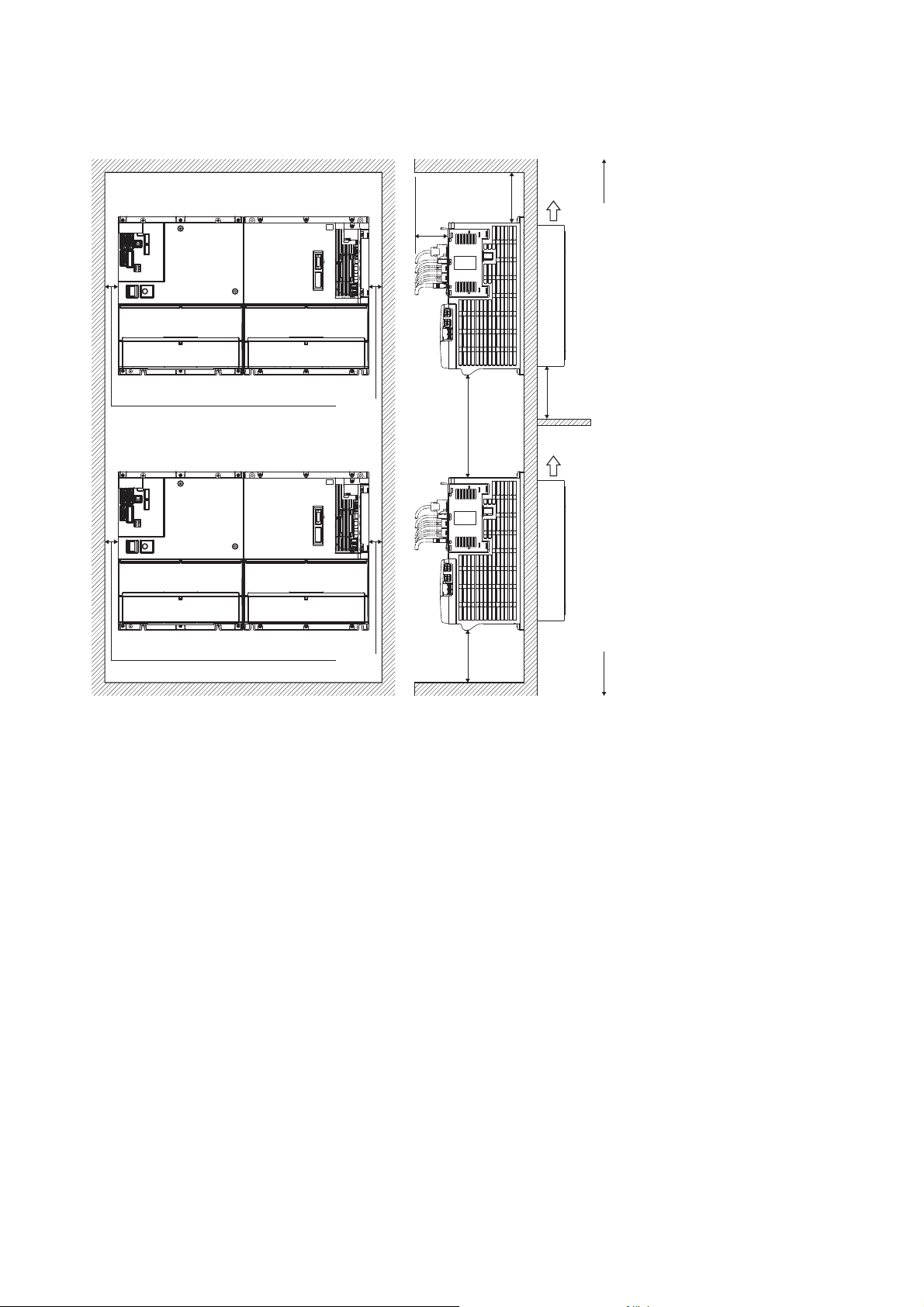
■Clearance between sets of combined power regeneration converter units and drive units
mounted above each other
220 mm
or more
Cooling
fan
exhaust
Top
*1
Cooling
100 mm
or more
Drive unitConverter unit
30 mm
Drive unitConverter unit
80 mm
or more
220 mm
or more
fan
exhaust
120 mm
30 mm
*1 Take measures, such as installing a shield, to prevent cooling fan exhaust of the lower unit from affecting the cooling fan on the upper
unit.
*2 A clearance of at least 120 mm is required. Leave a clearance, taking into consideration the flexibility of the cable.
or more
*2
Side
Bottom
18
2 INSTALLATION
2.1 Installation direction and clearances
Page 21
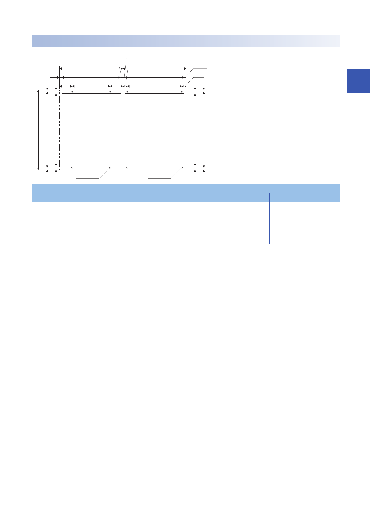
Mounting hole process drawing
Power regeneration
converter unit
Opening
Drive unit
Opening
380
360 ± 0.5 10(10)
342 19
(19)
4-M5 screw
W6
W8
W7
W9
(W10)
(W8)
W10
(W3)
360 ± 0.5 10(10)
342 19(19)
W1
W3
W4
W2
(W5)
W5
4-M5 screw
Unit Variable dimensions [mm]
W1 W2 W3 W4 W5 W6 W7 W8 W9 W10
Power regeneration converter
unit
Drive unit MR-J4-DU45KB4-RJ100
MR-CV55K4 300 180
0.5
300 260
MR-J4-DU55KB4-RJ100
60 282 9
2
20 281 9.5
0.5
2 INSTALLATION
2.1 Installation direction and clearances
19
Page 22
3 SIGNALS AND WIRING
U
Servo motor
MV
W
U
V
W
Drive unit
U
Servo motor
MV
W
U
V
W
Drive unit
WARNING
• Any person who is involved in wiring should be fully competent to do the work.
• Before wiring, turn off the power and wait for 20 minutes or more until the charge lamp turns off. Then, confirm that the voltage between L+ and L- is safe with
a voltage tester or others. Otherwise, an electric shock may occur. In addition, when confirming whether the charge lamp is off or not, always confirm it from
the front of the converter unit.
• Ground the converter unit, drive unit, and servo motor securely.
• Do not attempt to wire the converter unit, drive unit, and servo motor until they have been installed. Otherwise, it may cause an electric shock.
• The cables should not be damaged, stressed, loaded, or pinched. Otherwise, it may cause an electric shock.
• To avoid an electric shock, insulate the connections of the power supply terminals.
CAUTION
• Wire the equipment correctly and securely. Otherwise, the servo motor may operate unexpectedly, resulting in injury.
• Connect cables to the correct terminals. Otherwise, a burst, damage, etc., may occur.
• Ensure that polarity (+/-) is correct. Otherwise, a burst, damage, etc., may occur.
• The surge absorbing diode installed to the DC relay for control output should be fitted in the specified direction. Otherwise, the converter unit and the drive
unit will malfunction and will not output signals, disabling the emergency stop and other protective circuits.
Converter unit
Drive unit
DOCOM
Control
output signal
For sink output interface
• Use a noise filter, etc., to minimize the influence of electromagnetic interference. Electromagnetic interference may affect the electronic equipment used near
the converter unit and the drive unit.
• Do not install a power capacitor, surge killer, or radio noise filter (optional FR-BIF(-H)) with the power line of the servo motor.
• Do not modify the equipment.
• Connect the drive unit power outputs (U/V/W) to the servo motor power inputs (U/V/W) directly. Do not connect a magnetic contactor and others between
them. Otherwise, it may cause a malfunction.
• Connecting a servo motor of the wrong axis to U, V, W, or CN2 of the drive unit may cause a malfunction.
• Before wiring, switch operation, etc., eliminate static electricity. Otherwise, it may cause a malfunction.
24 V DC
RA
Converter unit
Drive unit
24 V DC
DOCOM
Control
output signal
For source output interface
RA
20
3 SIGNALS AND WIRING
Page 23
The following items are the same as those for MR-J4-_B_(-RJ). Refer to the section of the detailed explanation field for
details. "MR-J4-_B_" means "MR-J4-_B_(-RJ) Servo Amplifier Instruction Manual". "MR-J4-DU_B_" means "MR-CV_/MR-
CR55K_/MR-J4-DU_(-RJ) Instruction Manual".
Item Detailed explanation
I/O signal connection example MR-J4-_B_ section 3.2
Explanation of power supply system MR-J4-DU_B_ sections 3.3 and 5.2
Connectors and pin assignment MR-J4-DU_B_ sections 3.3 and 5.2
Signal (device) explanations MR-J4-_B_ section 3.5
Forced stop deceleration function MR-J4-_B_ section 3.6
Interface MR-J4-DU_B_ section 3.3
SSCNET III cable connection MR-J4-_B_ section 3.9
3.1 Connection example of power circuit
WARNING
• Insulate the connections of the power supply terminals. Otherwise, an electric shock may occur.
CAUTION
• Be sure to connect a magnetic contactor between the power supply and the main circuit power supply (L1/L2/L3) of the power regeneration converter unit, in
order to configure a circuit that shuts off the power supply by the power regeneration converter unit. If a magnetic contactor is not connected, continuous flow
of a large current may cause a fire when the power regeneration converter unit or the drive unit malfunctions.
• Use ALM (Malfunction) to shut the power off. Not doing so may cause a fire when the power regeneration converter unit malfunctions and causes the AC
reactor to overheat.
• The power regeneration converter unit has a built-in surge absorber (varistor) to reduce exogenous noise and to suppress lightning surge. Exogenous noise
or lightning surge deteriorates the varistor characteristics, and the varistor may be damaged. To prevent a fire, use a molded-case circuit breaker or fuse for
the input power supply.
• Check the power regeneration converter unit model, and then input proper voltage to the power regeneration converter unit power supply. If input voltage
exceeds the upper limit, the power regeneration converter unit and the drive unit will break down.
3
For drive units, EM2 has the same function as EM1 in the torque control mode.
Even if alarm has occurred, do not switch off the control circuit power supply. When the control circuit power
supply is shut off, an optical module does not operate, and optical transmission of SSCNET III/H
communication is interrupted. Therefore, the next servo amplifiers and drive units show "AA" on the display
and shut off the base circuit, stopping the servo motor with the dynamic brake.
For the magnetic contactor control connector (CN23), refer to section 3.3 in "MR-CV_/MR-CR55K_/MR-J4-
DU_(-RJ) Instruction Manual".
If the control axis No. is not be set correctly, or an SSCNET III cable is not be connected, the relay may switch
on and off repeatedly. Check the control axis No. setting and SSCNET III cable connection.
3 SIGNALS AND WIRING
3.1 Connection example of power circuit
21
Page 24
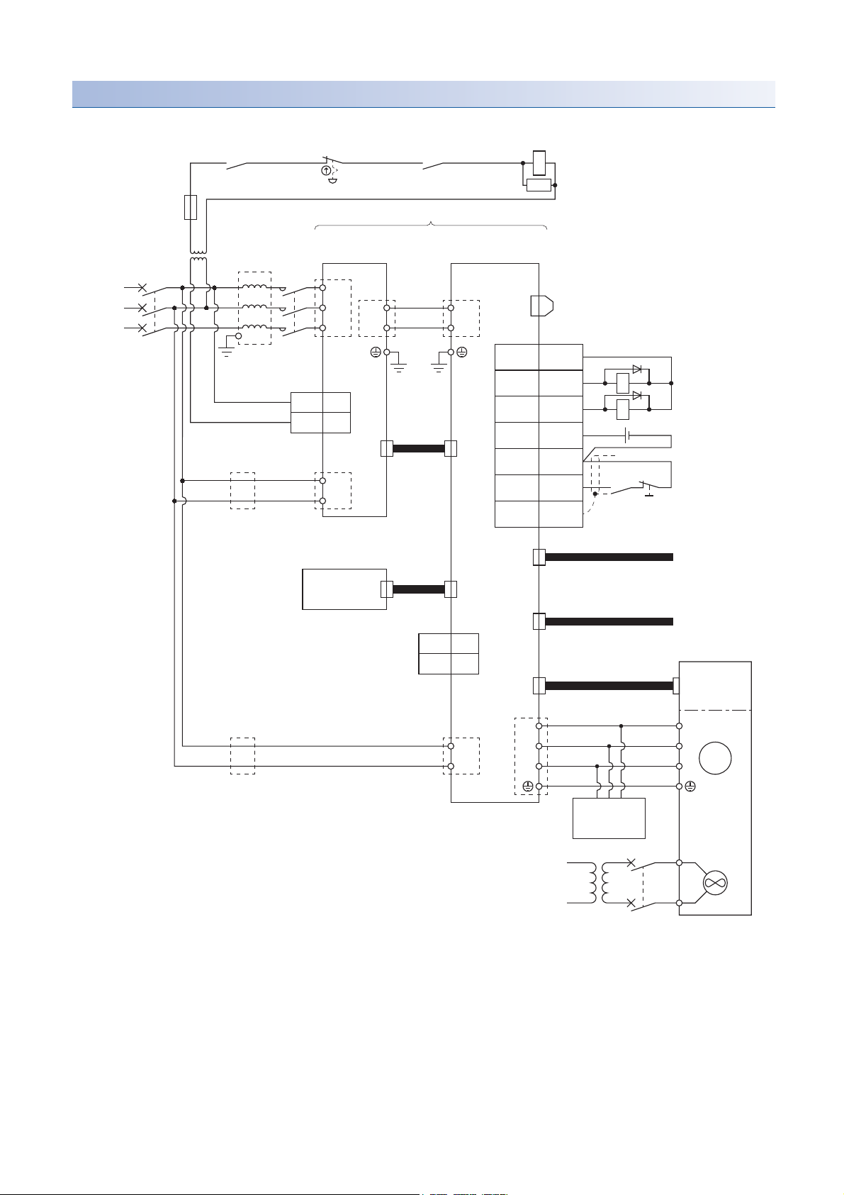
Connection example of encoder master servo amplifier
Drive unit
malfunction
*10
RA1
Operation ready
OFF/ON
Emergency
stop switch
MCCB
Power
supply
3-phase
380 V AC to
480 V AC
*16
Power regeneration
converter unit 1
MR-CV55K4
1MC1
3
MC2
CN23
TE3
CN4
1BAT
2LG
CN40A
CN1A
CN1B
CN4
CN2L
CN2
L1
L2
L3
L+
L-
AC
reactor
*14
MC
*5
L11
L21
L+
L-
Protection
coordination
cable
*11
Main circuit
power supply
*1
M
Encoder
Servo motor
BV
BU
Cooling
fan
V1
U1
W1
V
U
W
Dynamic
brake
(optional)
CN3
CN8
MR-ENE4CBL_M-H-MTH
*19
To CN1A on
drive unit 2 of
encoder slave
servo amplifier 1
To CN2 on
drive unit 2 of
encoder slave
servo amplifier 1
*8
TE2-2
TE2-1
TE1
Servo system
controller
TE3
TE1
L11
L21
MCCB
Encoder master servo amplifier
Step-down
transformer
*15
*13
*13
*2, *17
*2, *17
*4
*7
*3
*9
*4
*4
*10
*12
*4
MR-J4CN2CBL_M-H
SSCNET III cable
SSCNET III
cable
Bus bar
24 V DC
RA3
RA1
EM2
3
20
SD
Plate
DICOM10
ALM15
DOCOM
*18
DB
5 DICOM
Drive unit 1
MR-J4-DU_KB4-RJ100
MC
SK
Power supply
*6
22
3 SIGNALS AND WIRING
3.1 Connection example of power circuit
Page 25

*1 To prevent an unexpected restart of the drive unit, configure a circuit to turn off EM2 (Forced stop 2) in the drive unit when the main
circuit power is turned off.
*2 Always match the phases of the power supply connected to L11 and L21 on the power regeneration converter unit and the drive unit with
the phases connected to L1 and L2. Otherwise, the drive unit and the power regeneration converter unit may malfunction.
*3 Always supply power to the cooling fan terminal. For specifications of the cooling fan power supply and how to detect a failure, refer to
"Servo Motor Instruction Manual (Vol. 3)".
*4 Connect the grounding wire from the servo motor to the protective earth (PE) terminal of the drive unit. Put the grounding wires of the
drive unit and the power regeneration converter unit together
into one on the protective earth (PE) terminal of the cabinet, and then connect to the ground. Connect the grounding wire of the servo
motor to only the drive unit of the encoder master servo amplifier. If the grounding wire of the servo motor is connected to two or more
drive units, the circulating current may pass through the grounding wire depending on wiring conditions. When connecting grounding
wires to two or more drive units, be sure to twist the wires of the drive unit power outputs (U/V/W).
*5 Use a magnetic contactor with an operation delay time (interval between current being applied to the coil until closure of contacts) of 80
ms or less.
*6 For absolute position detection systems, connect an optional battery to only the drive unit of the encoder master servo amplifier. Do not
connect the optional battery to the drive units of the encoder slave servo amplifiers.
*7 Use an external dynamic brake (option) together. Failure to do so will cause an accident, such as machine collision because the servo
motor does not stop immediately but coasts at emergency stop. For wiring of the dynamic brake, refer to the following.
Page 69 External dynamic brake
*8 Encoder signals are distributed to all the drive units in the system via each drive unit.
*9 This diagram shows sink I/O interface. For source I/O interface, refer to section 3.8.3 in MR-J4-_B_(-RJ) Servo Amplifier Instruction
Manual.
*10 Configure a sequence that will shut off the main circuit power when an alarm occurs.
*11 Configure a circuit to simultaneously turn on or off EM2 (Forced stop 2) in the drive units of the encoder master servo amplifier and
encoder slave servo amplifiers.
*12 When not using the STO function, always attach the short-circuit connector supplied with the drive unit.
*13 If the wire size used for the branch circuit is smaller than that used for L1, L2, and L3, install an overcurrent protection device (molded-
case circuit breaker, fuse, or others) to protect the circuit.
*14 Even if an AC reactor is installed on the power regeneration converter unit, the functions operate normally.
*15 A step-down transformer is required when the coil voltage of the magnetic contactor is 200 V class.
*16 Supply power to all the servo amplifiers (power regeneration converter units and drive units) from the same power source. If power is
supplied from different power sources, a difference may be generated between outputs of the encoder master servo amplifier and that of
encoder slave servo amplifiers. This may cause the servo motor to operate unpredictably.
*17 Switch on the control circuit power supplies of all the servo amplifiers (power regeneration converter units and drive units)
simultaneously.
*18 The dynamic brake must be controlled by the drive unit of the encoder master servo amplifier. Assign DB (Dynamic brake interlock) in
[Pr. PD07] to [Pr. PD09].
*19 The encoder cable has a thermistor signal wire. Wiring the thermistor signal is unnecessary.
3
3 SIGNALS AND WIRING
3.1 Connection example of power circuit
23
Page 26
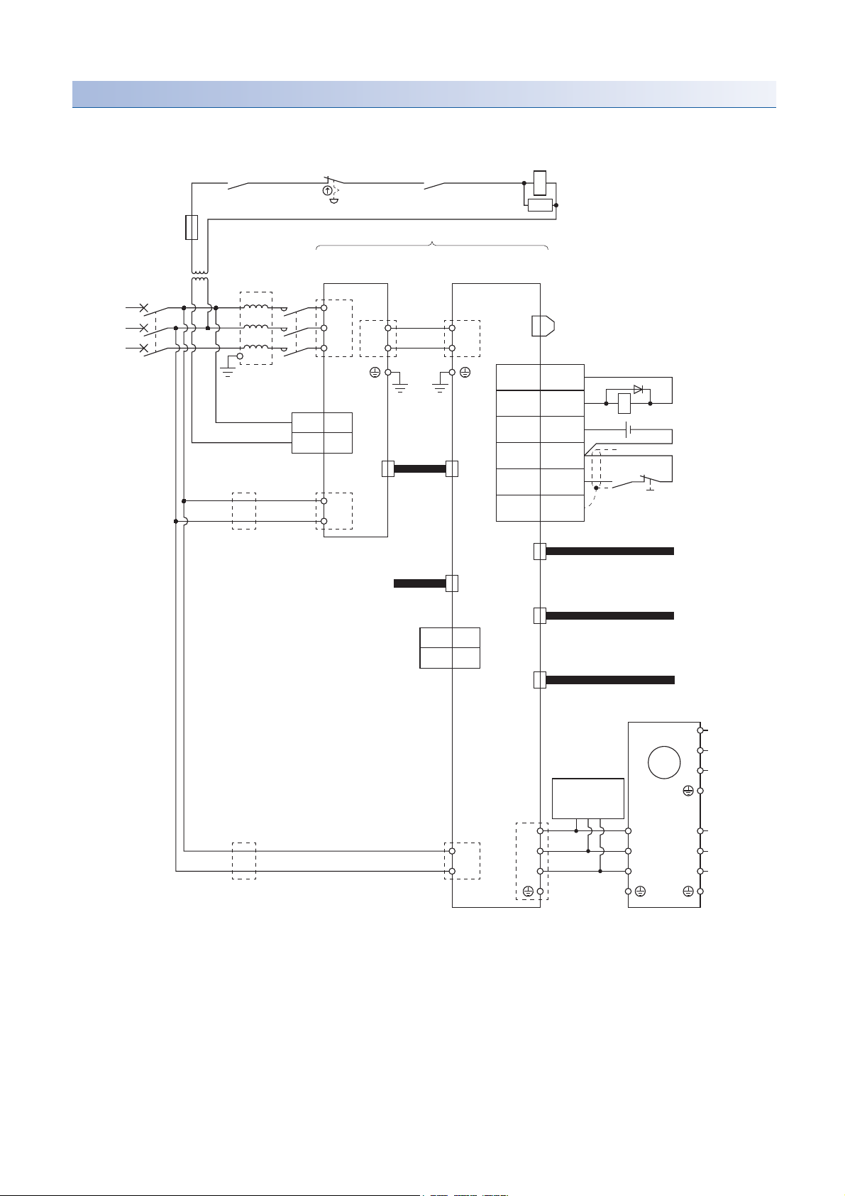
Connection example of encoder slave servo amplifier
This example is the connection for the encoder slave servo amplifier 1.
Step-down
transformer
Power
supply
3-phase
380 V AC to
480 V AC
Drive unit
malfunction
RA2
*10
Emergency
stop switch
Operation ready
OFF/ON
MC
SK
Encoder slave servo amplifier 1
Power regeneration
*15
MCCB
*16
AC
reactor
*14
MC
converter unit 2
TE1
*20
L1
L2
L3
MR-CV55K4
TE2-2
L+
L-
Bus bar
*4
Drive unit 2
MR-J4-DU_KB4-RJ100
TE2-1
L+
L-
*4
CN8
CN3
*12
*9
DICOM10
CN23
1MC1
CN4
Protection
coordination
cable
CN40A
Plate
3
MC2
*13
*2, *17
TE3
L11
ALM15
5 DICOM
DOCOM
3
EM2
20
SD
RA2
24 V DC
Main circuit
power supply
*10
*11
*1
L21
To CN1A on
drive unit 3 of
encoder slave
servo amplifier 2
To CN2 on
drive unit 3 of
encoder slave
servo amplifier 2
To CN2L on
drive unit 1 of
encoder master
servo amplifier
*5
*5, *8
*8
To CN1B on drive unit 1 of
encoder master servo amplifier
SSCNET III
cable
*6
CN1A
CN4
1BAT
2LG
CN1B
SSCNET III cable
MR-J4CN2CBL_M-H
CN2L
MR-J4CN2CBL_M-H
CN2
Servo motor
U3
To drive unit 3
of encoder
slave
V3
W3
*4
U4
V4
W4
*4
servo
amplifier 2
To drive unit 4
of encoder
slave
servo
amplifier 3
*5
*5
M
Dynamic
*7
brake
TE1
*13
*2, *17
TE3
L11
L21
U
V
W
*4
(optional)
U2
V2
W2
*4
24
3 SIGNALS AND WIRING
3.1 Connection example of power circuit
Page 27

*1 To prevent an unexpected restart of the drive unit, configure a circuit to turn off EM2 (Forced stop 2) in the drive unit when the main
circuit power is turned off.
*2 Always match the phases of the power supply connected to L11 and L21 on the power regeneration converter unit and the drive unit with
the phases connected to L1 and L2. Otherwise, the drive unit and the power regeneration converter unit may malfunction.
*3 Use a magnetic contactor with an operation delay time (interval between current being applied to the coil until closure of contacts) of 80
ms or less.
*4 Connect the grounding wire from the servo motor to the protective earth (PE) terminal of the drive unit. Put the grounding wires of the
drive unit and the power regeneration converter unit together
into one on the protective earth (PE) terminal of the cabinet, and then connect to the ground. Connect the grounding wire of the servo
motor to only the drive unit of the encoder master servo amplifier. If the grounding wire of the servo motor is connected to two or more
drive units, the circulating current may pass through the grounding wire depending on wiring conditions. When connecting grounding
wires to two or more drive units, be sure to twist the wires of the drive unit power outputs (U/V/W).
*5 This is for connecting four drive units and four power regeneration converter units to the servo motor.
*6 For the absolute position detection system, connect an optional battery to only the drive unit of the encoder master servo amplifier. Do
not connect the optional battery to the drive units of the encoder slave servo amplifiers.
*7 Use an external dynamic brake (option) together. Failure to do so will cause an accident, such as machine collision because the servo
motor does not stop immediately but coasts at emergency stop. For wiring of the dynamic brake, refer to the following.
Page 69 External dynamic brake
*8 Encoder signals are distributed to all the drive units in the system via each drive unit.
*9 This diagram shows sink I/O interface. For source I/O interface, refer to section 3.8.3 in MR-J4-_B_(-RJ) Servo Amplifier Instruction
Manual.
*10 Configure a sequence that will shut off the main circuit power when an alarm occurs.
*11 Configure a circuit to simultaneously turn on or off EM2 (Forced stop 2) in the drive units of the encoder master servo amplifier and
encoder slave servo amplifiers.
*12 When not using the STO function, always attach the short-circuit connector supplied with the drive unit.
*13 If the wire size used for the branch circuit is smaller than that used for L1, L2, and L3, install an overcurrent protection device (molded-
case circuit breaker, fuse, or others) to protect the circuit.
*14 Even if an AC reactor is installed on the power regeneration converter unit, the functions operate normally.
*15 A step-down transformer is required when the coil voltage of the magnetic contactor is 200 V class.
*16 Supply power to all the servo amplifiers (power regeneration converter units and drive units) from the same power source. If power is
supplied from different power sources, a difference may be generated between outputs of the encoder master servo amplifier and that of
encoder slave servo amplifiers. This may cause the servo motor to operate unpredictably.
*17 Switch on the control circuit power supplies of all the servo amplifiers (power regeneration converter units and drive units)
simultaneously.
3
3 SIGNALS AND WIRING
3.1 Connection example of power circuit
25
Page 28

3.2 Alarm occurrence timing chart
Power
regeneration
converter unit 4
Drive
unit 4
Encoder slave servo amplifier 3
Power
regeneration
converter unit 3
Drive
unit 3
Encoder slave servo amplifier 2
Power
regeneration
converter unit 2
Drive
unit 2
Encoder slave servo amplifier 1
SSCNET III/H
Servo system
controller
Power
regeneration
converter unit 1
Drive
unit 1
Encoder master servo amplifier
Servo motor
Alarm non-occurrence axis Alarm occurrence axis Alarm non-occurrence axis Alarm non-occurrence axis
Alarm occurrence
CAUTION
• When an alarm has occurred, remove its cause, make sure that the operation signal is not being inputted, ensure safety, and reset the alarm before
restarting operation.
When SSCNET III/H communication is shut off, the servo motor stops with the dynamic brake.
In the torque control mode, the forced stop deceleration function is unavailable.
This section describes MR-J4-DU_B4-RJ100 drive units only. For MR-CV55K4_power regeneration converter
units, refer to section 3.3 in "MR-CV_/MR-CR55K_/MR-J4-DU_(-RJ) Instruction Manual".
To deactivate the alarm, cycle the control circuit power or give the error reset or CPU reset command from the servo system
controller. However, the alarm cannot be deactivated unless its cause is removed.
Timing charts in this section show that an alarm occurs in any axis in the four axis of the parallel drive system.
3 SIGNALS AND WIRING
26
3.2 Alarm occurrence timing chart
Page 29

When you use the forced stop deceleration function
Set [Pr. PA04] to "2 _ _ _" (initial value).
Time constant setting
When you use the forced stop deceleration function, set the same value in the forced stop deceleration time constant [Pr.
PC24] of the drive unit and the rapid stop deceleration time set with the Motion controller.
■Difference between the deceleration time constant and the deceleration time
The following shows the difference between the forced stop deceleration time constant and the rapid stop deceleration time.
• Forced stop deceleration time constant (Drive unit)
The time for the servo motor to stop from the rated speed
[r/min]
Servo motor rated speed
Command speed
[ms]
Time required for the
servo motor to stop
Forced stop deceleration
time constant [Pr. PC24]
• Rapid stop deceleration time (Motion controller)
Time for the servo motor to stop from the speed limit value of the Motion controller
3
Speed limit value
Command speed
[pulse/s]
[ms]
Time required for the
servo motor to stop
Rapid stop deceleration time
3 SIGNALS AND WIRING
3.2 Alarm occurrence timing chart
27
Page 30

■Formula for calculating the rapid stop deceleration time
Rapid stop deceleration time [ms] =
Forced stop deceleration time constant [ms] × Speed limit value [pulse/s]
*1
× 60 [s]
Servo motor rated speed [r/min] × 4194304 [pulse]
Rapid stop deceleration time [ms] =
1000 × 2097152 × 60
2000 × 4194304
= 15 [ms]
*1 In addition to [pulse/s], [mm/min], [inch/min], and [degree/min] are used for the control unit of the Motion controller. When a control unit
other than [pulse/s] is used, convert the unit into [pulse/s] to calculate the rapid stop deceleration time.
■Setting example of the rapid stop deceleration time
Condition
Servo motor rated speed: 2000 [r/min] (Depends on the servo motor)
Speed limit value: 2097152 [pulse/s] (Depends on users, setting by the motion controller)
Forced stop deceleration time constant: 1000 [ms] (Depends on users, setting by the drive unit)
Therefore, set the rapid stop deceleration time of the motion controller to 1 ms.
If an alarm subject to the forced stop deceleration function occurs
The following timing chart shows that an alarm occurs in any axis in the parallel drive system.
Alarm occurrence
Model speed command is 0,
and the speed is equal to
or less than zero speed
Servo motor speed
*1
Alarm occurrence axis
Alarm non-occurrence axis
Base circuit
(Energy supply to
the servo motor)
Drive unit display
ALM (Malfunction)
Servo motor speed
Base circuit
(Energy supply to
the servo motor)
Drive unit display
ALM (Malfunction)
0 r/min
ON
OFF
ON (no alarm)
OFF (alarm)
0 r/min
ON
OFF
ON (no alarm)
OFF (alarm)
No alarm
The command from the
controller is not received.
Alarm No.No alarm
The command from the
controller is not received.
Alarm E7
Model speed command is 0,
and the speed is equal to
or less than zero speed
*1
*1 The model speed command is a speed command generated in the servo amplifier for forced stop deceleration of the servo motor.
28
3 SIGNALS AND WIRING
3.2 Alarm occurrence timing chart
Page 31

If an alarm not subject to the forced stop deceleration function occurs
ON
OFF
0 r/min
Braking by the dynamic brake
Braking by the dynamic brake
ON
OFF
0 r/min
ON (no alarm)
OFF (alarm)
Base circuit
(Energy supply to
the servo motor)
Base circuit
(Energy supply to
the servo motor)
Drive unit display
Servo motor speed
ALM (Malfunction)
ON (no alarm)
OFF (alarm)
Drive unit display
Servo motor speed
ALM (Malfunction)
Alarm occurrence axis
Alarm non-occurrence axis
Alarm occurrence
Alarm No.No alarm
No alarm
When the dynamic brake is used, a brake operation delay time occurs. For details, refer to the specifications
of the magnetic contactor you use.
The following timing chart shows that an alarm occurs in any axis in the parallel drive system.
3
3.2 Alarm occurrence timing chart
3 SIGNALS AND WIRING
29
Page 32

When SSCNET III/H communication is shut off
Axis in which SSCNET III/H
communication shut-off
has not occurred
Occurrence of SSCNET III/H communication shut-off
AA
ON
OFF
0 r/min
Axis in which SSCNET III/H
communication shut-off
has occurred
ON
OFF
0 r/min
Ab
Base circuit
(Energy supply to
the servo motor)
ON (no alarm)
OFF (alarm)
ON (no alarm)
OFF (alarm)
Drive unit display
Servo motor speed
ALM (Malfunction)
Base circuit
(Energy supply to
the servo motor)
Drive unit display
Servo motor speed
ALM (Malfunction)
Braking by the dynamic brake
No alarm
Braking by the dynamic brake
No alarm
When an SSCNET III/H communication shut-off occurs in a servo amplifier, the servo amplifier and
subsequent servo amplifiers show "AA" on the display.
When you do not use the forced stop deceleration function
Set [Pr. PA04] to "0 _ _ _". The operation status of the servo motor during an alarm is the same as that of when the forced stop
deceleration function is used.
Page 27 When you use the forced stop deceleration function
30
3 SIGNALS AND WIRING
3.2 Alarm occurrence timing chart
Page 33

3.3 Grounding
Converter
unit
Drive
unit
Converter
unit
Drive
unit
Converter
unit
Drive
unit
Converter
unit
Drive
unit
Copper bar
Converter
unit
Drive
unit
Other
device
Converter
unit
Drive
unit
Other
device
Good example Bad example
WARNING
• Ground the power regeneration converter unit, drive unit, and servo motor securely.
• To prevent an electric shock, be sure to connect the protective earth (PE) terminal (marked ) of the power regeneration converter unit and the drive unit to
the protective earth (PE) of the cabinet.
For items other than the ones described in this section, refer to section 3.3 in "MR-CV_/MR-CR55K_/MR-J4-
DU_(-RJ) Instruction Manual".
Capacitances exist between input/output lines of the servo and other lines or the ground, and in the servo motor, through
which a leakage current flows. For a servo with a large capacity, a leakage current including a high-frequency of several 100
mA may flow.
Note the following.
• To prevent an electric shock, be sure to ground the drive unit, power regeneration converter unit, and servo motor.
• To lower the impedance of the grounding wire, use the wire of the size equal to or greater than that shown in section 8.4 in
"MR-CV_/MR-CR55K_/MR-J4-DU_(-RJ) Instruction Manual", and make the wire as short as possible. Stranded wires or
braided wires are helpful to lower impedance.
• Prevent multiple points from being grounded. Ground one point. Grounding multiple points may generate a potential
difference between the grounded points by the impedance of the grounding wires. If the units cannot be grounded to one
point, connect the grounding wires to a copper bar and ground it to one point.
3
• Leakage currents including high-frequency components flow through the grounding wires of the drive unit, power
regeneration converter unit, and servo motor. Route the grounding wires of noise-sensitive devices separately.
• Route the grounding wires as far away from the input/output lines of noise-sensitive devices as possible, and run the
grounding wires in parallel to each other as short as possible.
• Connect the grounding wire from the servo motor to the protective earth (PE) terminal of the drive unit. Put the grounding
wires of the drive unit and the power regeneration converter unit together into one on the protective earth (PE) terminal of
the cabinet, and then connect to the ground. Connect the grounding wire of the servo motor to only the drive unit of the
encoder master servo amplifier. If the grounding wire of the servo motor is connected to two or more drive units, the
circulating current may pass through the grounding wire depending on wiring conditions. When connecting grounding wires
to two or more drive units, be sure to twist the wires of the drive unit power outputs (U/V/W).
3 SIGNALS AND WIRING
3.3 Grounding
31
Page 34

4 STARTUP
WARNING
• When executing a test run, follow the notice and procedures in this instruction manual. Otherwise, it may cause a malfunction, damage to the machine, or
injury.
• Do not operate the switches with wet hands. Otherwise, it may cause an electric shock.
CAUTION
• Before starting operation, check the parameters. Improper settings may cause some machines to operate unexpectedly.
• The heat sink of the power regeneration converter unit and drive unit, and the servo motor, etc. may be hot while power is on and for some time after poweroff. Take safety measures such as providing covers to avoid accidentally touching them by hands and parts such as cables.
• During operation, never touch the rotor of the servo motor. Otherwise, it may cause injury.
• Before wiring, switch operation, etc., eliminate static electricity. Otherwise, it may cause a malfunction.
For parallel drive systems, test operation cannot be performed with MR Configurator2. Perform test operation
with the controller.
The following items are the same as those for MR-J4-_B_(-RJ). Refer to the section of the detailed explanation field for
details. "MR-J4-_B_" means "MR-J4-_B_(-RJ) Servo Amplifier Instruction Manual". "MR-J4-DU_B_" means "MR-CV_/MR-
CR55K_/MR-J4-DU_(-RJ) Instruction Manual".
Item Detailed explanation
Switch setting and display of the drive unit MR-J4-_B_ section 4.3
Switch setting and operation section of power regeneration converter unit MR-J4-DU_B_ section 3.4
32
4 STARTUP
Page 35

4.1 Switching power on for the first time
Start up the parallel drive system in the following procedure. Once settings are made, they do not need to be reset. When
changes are made to the system settings of the Motion controller, and the drive unit is replaced, start up the system in the
following procedure again.
"MR-J4-_B_" means "MR-J4-_B_(-RJ) Servo Amplifier Instruction Manual". "MR-J4-DU_B_" means "MR-CV_/MR-CR55K_/
MR-J4-DU_(-RJ) Instruction Manual".
Setting
classification
Servo amplifier
Controller
Servo amplifier
Step Description Reference
1. Wiring check
2. Surrounding environment
check
3. Controller setting
4. Controller power on
5. System setting
6. Servo data setting
7. Controller reset
8. MR-CV55K4_ power
Check whether the power regeneration converter unit, drive
unit, and servo motor are wired correctly.
Check the surrounding environment of the power
regeneration converter unit, the drive unit and the servo
motor.
Make the controller settings (normal and the following
settings specific to the parallel drive system).
The parallel drive system is identified as the one axis of the
servo amplifier in the SSCNET configuration of MT
Developer2.
Set the system settings with the encoder master servo
amplifier.
When the system is set with the encoder slave servo
amplifier, an error may occur.
Set the following servo parameters with MR Configurator2 of
MT Developer2. Set the servo parameter for the drive unit of
the encoder master servo amplifier.
• [Pr. PA02 Regenerative option]
• [Pr. PA17 Servo motor series setting]
• [Pr. PA18 Servo motor type setting]
• [Pr. PC04 Function selection C-1]
• [Pr. PF37 Parallel drive - Encoder ID setting 1]
• [Pr. PF40 Parallel drive - Servo motor side system setting]
• [Pr. PF41 Function selection F-12]
• [Pr. PF42 Function selection F-13]
Set the converter setting rotary switch (SW1) to "0".
MR-J4-DU_B_ section 3.4
MR-J4-_B_ section 4.1.3
Chapter 5
regeneration converter unit
setting
9. Axis number setting of the
drive unit
10. Drive unit and Converter unit
power on
11. Drive unit and Converter unit
power off
12. Drive unit and Converter unit
power on
Check the control axis No. set with the auxiliary axis number
setting switches (SW2-3 and SW2-4) and the axis selection
rotary switch (SW1) match the control axis No. set with the
servo system controller.
The 3-digit, 7-segment LED of the drive unit displays the
following.
Encoder master servo amplifier: 16
Encoder slave servo amplifier: 16
[AL. 16 Encoder initial communication error 1] will occur
because the servo parameters set for the encoder master
servo amplifier via the controller (MT Developer 2) are not
applied. Apply the servo parameters to the drive unit in the
next step.
Enable the servo parameters set for the encoder master
amplifier via the controller (MT Developer 2).
The startup is completed.
The 3-digit, 7-segment LED of the drive unit displays the
following.
Encoder master servo amplifier: b##
Encoder slave servo amplifier: b.##
"##" means each axis number. The decimal point in the 2nd
digit is lit on the 3-digit, 7-segment LED display of the drive
unit set for the encoder slave servo amplifier.
MR-J4-_B_ section 4.3.1 (3)
4
4 STARTUP
4.1 Switching power on for the first time
33
Page 36

4.2 Startup
Startup of the MR-J4-DU_B4-RJ100 is the same as that of the MR-J4-_B_(-RJ). For details, refer to section 4.2 in "MR-J4-
_B_(-RJ) Servo Amplifier Instruction Manual".
The power regeneration converter unit shows "C" (ready-off) on the display at power-on.
When an alarm occurs or EM1 (Forced stop) is disabled in the power regeneration converter unit, the operation will stop.
34
4 STARTUP
4.2 Startup
Page 37

5 PARAMETERS
CAUTION
• Never make a drastic adjustment or change to the parameter values as doing so will make the operation unstable.
• Do not change the parameter settings as described below. Doing so may cause an unexpected condition, such as failing to start up the drive unit. Changing
the values of the parameters for manufacturer setting Setting a value out of the range Changing the fixed values in the digits of a parameter
• When you write parameters with the controller, make sure that the control axis No. of the drive unit is set correctly. Otherwise, the parameter settings of
another axis may be written, possibly causing the drive unit to be an unexpected condition.
When you connect the drive unit to a servo system controller, servo parameter values of the servo system
controller will be written to each parameter.
Setting may not be made to some parameters and their ranges depending on the servo system controller
model, drive unit software version, and MR Configurator2 software version. For details, refer to the servo
system controller user's manual.
The parameter whose symbol is preceded by * is enabled with the following conditions.
• *: After setting the parameter, cycle the power or reset the controller.
• **: After setting the parameter, cycle the power.
Set a value to each "x" in the "Setting digit" columns.
Do not change parameters during servo-on.
Be sure to set the same setting in parameters of the encoder master servo amplifier and those of the encoder
slave servo amplifiers.
When the parameters are written with MR Configurator2, be sure to be connected via the motion controller. If
parameters are written with MR Configurator2 by directly connecting to the USB port on the drive unit,
parameters in the drive unit and the controller cannot be updated correctly.
For the advanced vibration suppression control II (vibration suppression control tuning) and the adaptive filter
II (adaptive tuning), "Automatic setting" is invalid. Only "Manual setting" is valid.
5
The following shows parameter settings exclusively for the driver unit. Other parameters are the same as those of MR-J4-
_B_(-RJ). Refer to chapter 5 in "MR-J4-_B_(-RJ) Servo Amplifier Instruction Manual".
[Pr. PA01 Operation mode (**STY)]
For parallel drive systems, the operation mode selection and J3 compatibility mode are unavailable. Do not change those
parameters.
Setting digit Explanation Initial value
_ _ _ x For manufacturer setting 0h
_ _ x _ Operation mode selection
0: Standard control mode
1: Fully closed loop control mode
4: Linear servo motor control mode
6: DD motor control mode
Setting any value other than "0” will trigger [AL. 37 Parameter error].
_ x _ _ For manufacturer setting 0h
x _ _ _ Compatibility mode selection
For parallel drive systems, the J3 compatibility mode is unavailable. Do not set this digit to "0".
0: J3 compatibility mode
1: J4 mode
0h
1h
5 PARAMETERS
35
Page 38

[Pr. PA02 Regenerative option (**REG)]
For parallel drive systems, the regenerative option is unavailable. Set "0700" to this parameter.
Setting digit Explanation Initial value
_ _ x x Regenerative option selection
00: Regenerative option is not used, or when you use a regenerative option, set the regenerative option with the converter
unit.
When using the drive unit with the converter unit, set this value regardless of whether or not the regenerative option and
brake unit are used.
_ x _ _ Converter unit selection
For parallel drive systems, the MR-CR_ is unavailable. Do not set this digit to "0".
0: MR-CR_
7: MR-CV_
Setting a value other than "0" or "7" will trigger [AL. 37].
x _ _ _ Protection coordination mode selection between converter and drive unit
For parallel drive systems, do not set this digit to "Protection coordination mode disabled (stand-alone drive) (4 _ _ _ )".
0: Protection coordination mode enabled
4: Protection coordination mode disabled (stand-alone drive)
00h
0h
0h
[Pr. PA17 Servo motor series setting (**MSR)]
Select any servo motor with [Pr. PA17] and [Pr. PA18]. Set this and [Pr. PA18] at a time. Refer to the following table for
settings.
Motor series Servo motor [Pr. PA17] [Pr. PA18]
HG-JR HG-JR110K24W0C 0132h A102h
HG-JR150K24W0C 0132h A502h
HG-JR180K24W0C 0132h A802h
HG-JR200K24W0C 0132h B002h
HG-JR220K24W0C 0132h B202h
Initial value [unit]: 0000h
[Pr. PA18 Servo motor type setting (**MTY)]
Select any servo motor with [Pr. PA17] and [Pr. PA18]. Set this and [Pr. PA17] at a time. Refer to the table of [Pr. PA17] for
settings.
Initial value [unit]: 0000h
[Pr. PA20 Tough drive setting (*TDS)]
Alarms may not be avoided with the tough drive function depending on the situations of the power supply and load fluctuation.
You can assign MTTR (During tough drive) to pins CN3-9, CN3-13, and CN3-15 with [Pr. PD07] to [Pr. PD09].
Setting digit Explanation Initial value
_ _ _ x For manufacturer setting 0h
_ _ x _ Vibration tough drive selection
0: Disabled
1: Enabled
Selecting "1" enables to suppress vibrations by automatically changing the setting values of [Pr. PB13 Machine resonance
suppression filter 1] and [Pr. PB15 Machine resonance suppression filter 2] in case that the vibration exceeds the value of
the oscillation level set in [Pr. PF23].
For details, refer to section 7.3 in "MR-J4-_B_(-RJ) Servo Amplifier Instruction Manual".
_ x _ _ SEMI-F47 function selection
A combination of the MR-CV55K4_ power regeneration converter unit and drive unit does not comply with SEMI-F47
standard.
0: Disabled
1: Enabled
When "MR-CV_ ( _ 7 _ _ )" is selected in "Converter unit selection" of [Pr. PA02], setting "Enabled ( _ 1 _ _ )" in this
parameter will trigger [AL. 37 Parameter error].
x _ _ _ For manufacturer setting 0h
0h
0h
36
5 PARAMETERS
Page 39

[Pr. PA21 Function selection A-3 (*AOP3)]
Setting digit Explanation Initial value
_ _ _ x One-touch tuning function selection
For parallel drive systems, the one-touch tuning is unavailable. The parameter setting is invalid.
0: Disabled
1: Enabled
_ _ x _ For manufacturer setting 0h
_ x _ _ 0h
x _ _ _ 0h
1h
[Pr. PB01 Adaptive tuning mode (adaptive filter II) (FILT)]
Set the adaptive tuning.
Setting digit Explanation Initial value
_ _ _ x Filter tuning mode selection
Select the adjustment mode of the machine resonance suppression filter 1. For parallel drive systems, "Automatic setting
(_ _ _ 1)" is invalid.
0: Disabled
1: Automatic setting
2: Manual setting
_ _ x _ For manufacturer setting 0h
_ x _ _ 0h
x _ _ _ Tuning accuracy selection
0: Standard
1:
The frequency is estimated more accurately in the high accuracy mode compared to the standard mode. However, the
tuning sound may be larger in the high accuracy mode.
0h
0h
5
[Pr. PB02 Vibration suppression control tuning mode (advanced vibration suppression
control II) (VRFT)]
Set the vibration suppression control tuning.
Setting digit Explanation Initial value
_ _ _ x Vibration suppression control 1 tuning mode selection
Select the tuning mode of the vibration suppression control 1. For parallel drive systems, "Automatic setting (_ _ _ 1)" is
invalid.
0: Disabled
1: Automatic setting
2: Manual setting
_ _ x _ Vibration suppression control 2 tuning mode selection
Select the tuning mode of the vibration suppression control 2. To enable the digit, select "3 inertia mode (_ _ _ 1)" of
"Vibration suppression mode selection" in [Pr. PA24 Function selection A-4]. For parallel drive systems, "Automatic setting
(_ _ 1 _)" is invalid.
0: Disabled
1: Automatic setting
2: Manual setting
_ x _ _ For manufacturer setting 0h
x _ _ _ 0h
0h
0h
[Pr. PC04 Function selection C-1 (**COP1)]
Select an encoder cable communication method.
Setting digit Explanation Initial value
_ _ _ x For manufacturer setting 0h
_ _ x _ 0h
_ x _ _ 0h
x _ _ _ Encoder cable communication method selection
For parallel drive systems, the two-wire type is unavailable. Set this digit to "1".
0: Two-wire type
1: Four-wire type
0h
5 PARAMETERS
37
Page 40

[Pr. PC24 Forced stop deceleration time constant (RSBR)]
Set a deceleration time constant for the forced stop deceleration function.
Set the time taken from the rated speed to 0 r/min in a unit of ms. Setting "0" will be 100 ms.
Dynamic brake
Rated speed
Servo motor speed
Forced stop deceleration
deceleration
0 r/min
[Pr. PC24]
[Precautions]
• If the servo motor torque is saturated at the maximum torque during a forced stop deceleration because the set time is too
short, the time to stop will be longer than the set time constant.
• [AL. 50 Overload alarm 1] or [AL. 51 Overload alarm 2] may occur during forced stop deceleration, depending on the set
value.
• After an alarm that leads to a forced stop deceleration, if an alarm that does not lead to a forced stop deceleration occurs or
if the control circuit power supply is cut, dynamic braking will start regardless of the deceleration time constant setting.
• Set the time the same as the rapid stop deceleration time set with the controller. If a shorter time is set, [AL. 52 Error
excessive] may occur. For the setting method, refer to the following.
Page 27 Time constant setting
Initial value [unit]: 100 [ms]
Setting range: 0 to 20000
[Pr. PF03 Function selection F-5 (*FOP5)]
Setting digit Explanation Initial value
_ _ _ x For manufacturer setting 0h
_ _ x _ 0h
_ x _ _ Protection coordination mode function between converter and drive unit selection
For parallel drive systems, set this digit to "0".
0: Disabled
1: Enabled
When "Enabled ( _ 1 _ _ )" is selected in this parameter, the setting value in "Protection coordination mode selection
between converter and drive unit" of [Pr. PA02] is enabled.
x _ _ _ For manufacturer setting 0h
0h
[Pr. PF07 Function selection F-6 (*FOP6)]
Setting digit Explanation Initial value
_ _ _ x For manufacturer setting 0h
_ _ x _ 0h
_ x _ _ Magnetic contactor shut-off selection at STO input
For parallel drive systems, the magnetic contactor turns off when STO is inputted (when [AL. 95] has occurred). The
setting value of "1" is disabled.
0: The magnetic contactor is turned off when STO is inputted (when [AL. 95] has occurred).
1: The magnetic contactor is kept on when STO is inputted (when [AL. 95] has occurred).
x _ _ _ Magnetic contactor shut-off selection at forced stop input
For parallel drive systems, the magnetic contactor turns off when the forced stop is inputted (when [AL. E6] has occurred).
0: Turns the magnetic contactor off when the forced stop is input (when [AL. E6] has occurred).
1: Keeps the magnetic contactor on when the forced stop is input (when [AL. E6] has occurred).
38
5 PARAMETERS
0h
0h
Page 41

[Pr. PF25 SEMI-F47 function - Instantaneous power failure detection time (CVAT)]
A combination of the MR-CV55K4_ power regeneration converter unit and drive unit does not comply with SEMI-F47
standard. The parameter setting is invalid.
Initial value [unit]: 200 [ms]
[Pr. PF37 Parallel drive - Encoder ID setting 1 (**ENID1)]
Set a servo motor-side encoder ID. Setting an encoder ID switches encoder communication types. Setting any value other
than the following will trigger [AL. 37 Parameter error].
When the MR-D30 functional safety unit is mounted on the encoder master servo amplifier
Setting
value
0444 HG-JR110K24W0C
When the MR-D30 functional safety unit is not mounted on the encoder master servo amplifier
Setting
value
0044 HG-JR110K24W0C
Servo motor
HG-JR150K24W0C
HG-JR180K24W0C
HG-JR200K24W0C
HG-JR220K24W0C
Servo motor
HG-JR150K24W0C
HG-JR180K24W0C
HG-JR200K24W0C
HG-JR220K24W0C
5
Initial value [unit]: 0000h
[Pr. PF40 Parallel drive - Servo motor side system setting (**EMS)]
Set the servo motor-side encoder slave servo amplifiers.
Setting digit Explanation Initial value
_ _ x x Control axis No. setting of the encoder master servo amplifier
Set the control axis No. of the encoder master servo amplifier in hexadecimal. When "00" is set, the parameter setting is
invalid.
x x _ _ The number setting of the encoder master servo amplifier
Set the number of encoder slave servo amplifiers. When "00" is set, the parameter setting is invalid.
00h
00h
Setting example:
If the control axis No. of the encoder master servo amplifier is 17 (11h), and three encoder slave servo amplifiers are used, set
"0311".
[Pr. PF41 Function selection F-12 (*FOP12)]
Enable/disable [AL. 46 Servo motor overheat] detection. For servo motors without a thermistor, [AL. 46 Servo motor overheat]
detection is disabled regardless of the setting. When [AL. 46 Servo motor overheat] detection is enabled, temperature
monitoring is also enabled regardless of the setting of [Pr. PF42 Parallel drive - Temperature monitor setting].
Setting digit Explanation Initial value
_ _ _ x
(HEX)
_ _ _ x
(BIN)
Encoder master servo amplifier - Motor thermistor setting
0: [AL. 46 Servo motor overheat] detection enabled
1: [AL. 46 Servo motor overheat] detection disabled
0h
5 PARAMETERS
39
Page 42

[Pr. PF42 Function selection F-13 (*FOP13)]
Enable/disable temperature monitoring. For servo motors without a thermistor, temperature monitoring is disabled regardless
of the set value. When [AL. 46 Servo motor overheat] detection is enabled in [Pr. PF41 Parallel drive - Motor thermistor
setting], temperature monitoring is also enabled regardless of the setting of [Pr. PF42 Parallel drive - Temperature monitor
setting].
Setting digit Explanation Initial value
_ _ _ x
(HEX)
_ _ _ x
(BIN)
Encoder master servo amplifier - Temperature monitor setting
0: Temperature monitoring enabled
1: Temperature monitoring disabled
0h
40
5 PARAMETERS
Page 43

6 TROUBLESHOOTING
• The forced stop deceleration does not function for alarms not subject to the forced stop deceleration
function.
For parallel drive systems, if [AL. 34 SSCNET receive error 1] or [AL. 36 SSCNET receive error 2] occurs, the servo motor
stops with the dynamic brake (DB), not with forced stop deceleration (SD).
6.1 Troubleshooting for MR-CV_ power regeneration
converter unit
When an alarm or warning is displayed, refer to "MELSERVO-J4 Servo Amplifier Instruction Manual (Troubleshooting)" to
remove the failure.
MELSERVO-J4 Servo Amplifier Instruction Manual (Troubleshooting)
When an alarm occurs, ALM (Malfunction) will turn off.
Explanation for the lists
No./Name
Indicates each No./Name of alarms or warnings.
6
Alarm deactivation
After the cause of the alarm has been removed, the alarm can be deactivated by any of the methods marked in the alarm
deactivation column. Warnings are automatically canceled after the cause of occurrence is removed. Alarms are deactivated
by alarm reset, CPU reset, or power cycling.
Alarm deactivation Explanation
Alarm reset 1. Turn on RES (Reset) with an input device.
2. Input the servo-on command for the drive unit connected with the protection coordination cable.
CPU reset Reset the controller itself.
Power cycling Turn the power off and on again.
*1 Deactivate the alarm in servo-off status. If the alarm is deactivated in servo-on status, [AL. 1B Converter error] will occur.
*2 If the protection coordination cable is not connected, the alarm cannot be deactivated by CPU reset.
*2
*1
6 TROUBLESHOOTING
6.1 Troubleshooting for MR-CV_ power regeneration converter unit
41
Page 44

Alarm list
No. Name Alarm deactivation
Alarm reset CPU reset Power cycling
61 Overcurrent
62 Frequency error
66 Process error
67 Open phase
68 Watchdog
69 Ground fault
6A MC drive circuit error
6B Inrush current suppression circuit error
6C Main circuit error
*1
6E_
70 Converter forced stop error
71 Undervoltage
72 Cooling fan error
73 Regenerative error
75 Overvoltage
76 Switch setting error
77 Main circuit device overheat
7E Overload 1
7F Overload 2
*1 Digits of "_” may be displayed. Remedies for the alarm is the same as those for [AL. 6E].
*2 After resolving the source of trouble, cool the equipment for approximately 30 minutes.
Board error
*2
*2
*2
*2
*2
*2
*2
*2
*2
*2
*2
Warning list
No. Name
E9 Instantaneous power failure warning
EA External forced stop warning
EB Excessive regeneration warning
EC Overload warning
EE Cooling fan speed reduction warning
42
6 TROUBLESHOOTING
6.1 Troubleshooting for MR-CV_ power regeneration converter unit
Page 45

6.2 Troubleshooting for drive unit
[AL. 37 Parameter error] and warnings (except [AL. F0 Tough drive warning]) are not recorded in the alarm
history.
When an error occurs during operation, the corresponding alarm or warning is displayed. When an alarm or warning is
displayed, refer to "MELSERVO-J4 Servo Amplifier Instruction Manual (Troubleshooting)" to remove the failure.
MELSERVO-J4 Servo Amplifier Instruction Manual (Troubleshooting)
When an alarm occurs, ALM (Malfunction) will turn off.
Explanation for the lists
No./Name/Detail No./Detail name
Indicates the No./name/detail No./detail name of alarms or warnings.
Stop method
For the alarms and warnings in which "SD" is written in the stop method column, the servo motor stops with the dynamic
brake after forced stop deceleration. For the alarms and warnings in which "DB" or "EDB" is written in the stop method
column, the servo motor stops with the dynamic brake without forced stop deceleration.
Alarm deactivation
After the cause of the alarm has been removed, the alarm can be deactivated by any of the methods marked in the alarm
deactivation column. Warnings are automatically canceled after the cause of occurrence is removed. Alarms are deactivated
by alarm reset, CPU reset, or power cycling.
Alarm deactivation Explanation
Alarm reset 1. Error reset command from the controller
2. Click "Occurred Alarm Reset" in the "Alarm Display" window of MR Configurator2.
CPU reset Reset the controller itself.
Power cycling Turn the power off and on again.
6
6 TROUBLESHOOTING
6.2 Troubleshooting for drive unit
43
Page 46

Alarm list
Alarm Details Stop
No. Name No. Name Alarm
10 Undervoltage 10.1 Voltage drop in the control circuit power EDB
10.2 Voltage drop in the main circuit power SD
11 Switch setting error 11.1 Axis number setting error/station number
setting error
11.2 Disabling control axis setting error DB
12 Memory error 1 (RAM) 12.1 RAM error 1 DB
12.2 RAM error 2 DB
12.3 RAM error 3 DB
12.4 RAM error 4 DB
12.5 RAM error 5 DB
12.6 RAM error 6 DB
13 Clock error 13.1 Clock error 1 DB
13.2 Clock error 2 DB
13.3 Clock error 3 DB
14 Control process error 14.1 Control process error 1 DB
14.2 Control process error 2 DB
14.3 Control process error 3 DB
14.4 Control process error 4 DB
14.5 Control process error 5 DB
14.6 Control process error 6 DB
14.7 Control process error 7 DB
14.8 Control process error 8 DB
14.9 Control process error 9 DB
14.A Control process error 10 DB
14.B Control process error 11 DB
14.C Control process error 12 DB
14.D Control process error 13 DB
15 Memory error 2 (EEP-ROM) 15.1 EEP-ROM error at power on DB
15.2 EEP-ROM error during operation DB
15.4 Home position information read error DB
method
*3
DB
Alarm deactivation
*2
reset
CPU
reset
Power
cycling
44
6 TROUBLESHOOTING
6.2 Troubleshooting for drive unit
Page 47

Alarm Details Stop
No. Name No. Name Alarm
16 Encoder initial communication error 116.1 Encoder initial communication - Receive
data error 1
16.2 Encoder initial communication - Receive
16.3 Encoder initial communication - Receive
16.4 Encoder initial communication - Encoder
16.5 Encoder initial communication -
16.6 Encoder initial communication -
16.7 Encoder initial communication -
16.8 Encoder initial communication -
16.A Encoder initial communication - Process
16.B Encoder initial communication - Process
16.C Encoder initial communication - Process
16.D Encoder initial communication - Process
16.E Encoder initial communication - Process
16.F Encoder initial communication - Process
17 Board error 17.1 Board error 1 DB
17.3 Board error 2 DB
17.4 Board error 3 DB
17.5 Board error 4 DB
17.6 Board error 5 DB
17.7 Board error 7 DB
17.8 Board error 6
17.9 Board error 8 DB
19 Memory error 3 (Flash-ROM) 19.1 Flash-ROM error 1 DB
19.2 Flash-ROM error 2 DB
19.3 Flash-ROM error 3 DB
1A Servo motor combination error 1A.1 Servo motor combination error 1 DB
1A.2 Servo motor control mode combination
1A.4 Servo motor combination error 2 DB
1B Converter error 1B.1 Converter unit error DB
1E Encoder initial communication error 21E.1 Encoder malfunction DB
1E.2 Load-side encoder malfunction DB
1F Encoder initial communication error 31F.1 Incompatible encoder DB
1F.2 Incompatible load-side encoder DB
data error 2
data error 3
malfunction
Transmission data error 1
Transmission data error 2
Transmission data error 3
Incompatible encoder
error 1
error 2
error 3
error 4
error 5
error 6
error
*6
*6
*6
method
*3
DB
DB
DB
DB
DB
DB
DB
DB
DB
DB
DB
DB
DB
DB
EDB
DB
Alarm deactivation
*2
reset
CPU
reset
Power
cycling
6
6 TROUBLESHOOTING
6.2 Troubleshooting for drive unit
45
Page 48

Alarm Details Stop
No. Name No. Name Alarm
20 Encoder normal communication
error 1
21 Encoder normal communication
error 2
24 Main circuit error 24.1 Ground fault detected at hardware
25 Absolute position erased 25.1 Servo motor encoder - Absolute position
27 Initial magnetic pole detection error 27.1 Initial magnetic pole detection - Abnormal
28 Linear encoder error 2 28.1 Linear encoder - Environment error EDB
2A Linear encoder error 1 2A.1 Linear encoder error 1-1 EDB
2B Encoder counter error 2B.1 Encoder counter error 1 EDB
20.1 Encoder normal communication Receive data error 1
20.2 Encoder normal communication Receive data error 2
20.3 Encoder normal communication Receive data error 3
20.5 Encoder normal communication Transmission data error 1
20.6 Encoder normal communication Transmission data error 2
20.7 Encoder normal communication Transmission data error 3
20.9 Encoder normal communication Receive data error 4
20.A Encoder normal communication Receive data error 5
21.1 Encoder data error 1 EDB
21.2 Encoder data update error EDB
21.3 Encoder data waveform error EDB
21.4 Encoder non-signal error EDB
21.5 Encoder hardware error 1 EDB
21.6 Encoder hardware error 2 EDB
21.9 Encoder data error 2 EDB
detection circuit
24.2 Ground fault detected by software
detection function
erased
25.2 Scale measurement encoder - Absolute
position erased
termination
27.2 Initial magnetic pole detection - Time out
error
27.3 Initial magnetic pole detection - Limit
switch error
27.4 Initial magnetic pole detection Estimated error
27.5 Initial magnetic pole detection - Position
deviation error
27.6 Initial magnetic pole detection - Speed
deviation error
27.7 Initial magnetic pole detection - Current
error
2A.2 Linear encoder error 1-2 EDB
2A.3 Linear encoder error 1-3 EDB
2A.4 Linear encoder error 1-4 EDB
2A.5 Linear encoder error 1-5 EDB
2A.6 Linear encoder error 1-6 EDB
2A.7 Linear encoder error 1-7 EDB
2A.8 Linear encoder error 1-8 EDB
2B.2 Encoder counter error 2 EDB
method
*3
EDB
EDB
EDB
EDB
EDB
EDB
EDB
EDB
DB
DB
DB
DB
DB
DB
DB
DB
DB
DB
DB
Alarm deactivation
*2
reset
CPU
reset
Power
cycling
46
6 TROUBLESHOOTING
6.2 Troubleshooting for drive unit
Page 49

Alarm Details Stop
No. Name No. Name Alarm
30 Regenerative error 30.1 Regeneration heat error DB
30.2 Regeneration signal error DB
30.3 Regeneration feedback signal error DB
method
*3
Alarm deactivation
*2
reset
*1
*1
*1
CPU
reset
*1
*1
*1
Power
cycling
*1
*1
*1
31 Overspeed 31.1 Abnormal motor speed SD
32 Overcurrent 32.1 Overcurrent detected at hardware
DB
detection circuit (during operation)
32.2 Overcurrent detected at software
DB
detection function (during operation)
32.3 Overcurrent detected at hardware
DB
detection circuit (during a stop)
32.4 Overcurrent detected at software
DB
detection function (during a stop)
33 Overvoltage 33.1 Main circuit voltage error EDB
34 SSCNET receive error 1 34.1 SSCNET receive data error DB
*5
34.2 SSCNET connector connection error DB
34.3 SSCNET communication data error DB
34.4 Hardware error signal detection DB
34.5 SSCNET receive data error (safety
DB
observation function)
34.6 SSCNET communication data error
DB
(safety observation function)
35 Command frequency error 35.1 Command frequency error SD
36 SSCNET receive error 2 36.1 Continuous communication data error DB
36.2 Continuous communication data error
DB
(safety observation function)
37 Parameter error 37.1 Parameter setting range error DB
37.2 Parameter combination error DB
37.3 Point table setting error DB
39 Program error 39.1 Program error DB
39.2 Instruction argument external error DB
39.3 Register No. error DB
39.4 Non-correspondence instruction error DB
3A Inrush current suppression circuit
3A.1 Inrush current suppression circuit error EDB
error
3D Parameter setting error for driver
communication
3D.1 Parameter combination error for driver
communication on slave
3D.2 Parameter combination error for driver
DB
DB
communication on master
3E Operation mode error 3E.1 Operation mode error DB
3E.6 Operation mode switch error DB
3E.8 MR-D30 combination error DB
42 Servo control error
(for linear servo motor and direct
drive motor)
42.1 Servo control error by position deviation EDB
42.2 Servo control error by speed deviation EDB
42.3 Servo control error by torque/thrust
EDB
*4 *4
*4 *4
*4 *4
deviation
Fully closed loop control error
(for fully closed loop control)
42.8 Fully closed loop control error by position
deviation
42.9 Fully closed loop control error by speed
EDB
EDB
*4 *4
*4 *4
deviation
42.A Fully closed loop control error by position
EDB
*4 *4
deviation during command stop
45 Main circuit device overheat 45.1 Main circuit device overheat error 1 SD
45.2 Main circuit device overheat error 2 SD
*1
*1
*1
*1
*1
*1
6
6 TROUBLESHOOTING
6.2 Troubleshooting for drive unit
47
Page 50

Alarm Details Stop
No. Name No. Name Alarm
46 Servo motor overheat 46.1 Abnormal temperature of servo motor 1 SD
46.2 Abnormal temperature of servo motor 2 SD
46.3 Thermistor disconnected error SD
46.4 Thermistor circuit error SD
46.5 Abnormal temperature of servo motor 3 DB
46.6 Abnormal temperature of servo motor 4 DB
method
*3
Alarm deactivation
*2
reset
*1
*1
*1
*1
*1
*1
CPU
reset
*1
*1
*1
*1
*1
*1
Power
cycling
*1
*1
*1
*1
*1
*1
47 Cooling fan error 47.1 Cooling fan stop error SD
47.2 Cooling fan speed reduction error SD
50 Overload 1 50.1 Thermal overload error 1 during
SD
*1
*1
*1
operation
50.2 Thermal overload error 2 during
SD
*1
*1
*1
operation
50.3 Thermal overload error 4 during
SD
*1
*1
*1
operation
50.4 Thermal overload error 1 during a stop SD
50.5 Thermal overload error 2 during a stop SD
50.6 Thermal overload error 4 during a stop SD
51 Overload 2 51.1 Thermal overload error 3 during
DB
*1
*1
*1
*1
*1
*1
*1
*1
*1
*1
*1
*1
operation
51.2 Thermal overload error 3 during a stop DB
*1
*1
*1
52 Error excessive 52.1 Excess droop pulse 1 SD
52.3 Excess droop pulse 2 SD
52.4 Error excessive during 0 torque limit SD
52.5 Excess droop pulse 3 EDB
54 Oscillation detection 54.1 Oscillation detection error EDB
56 Forced stop error 56.2 Over speed during forced stop EDB
56.3 Estimated distance over during forced
EDB
stop
56.4 Forced stop starting error EDB
61 Operation error 61.1 Point table setting error DB
63 STO timing error 63.1 STO1 off DB
63.2 STO2 off DB
63.5 STO by functional safety unit DB
64 Functional safety unit setting error 64.1 STO input error DB
64.2 Compatibility mode setting error DB
64.3 Operation mode setting error DB
65 Functional safety unit connection
error
65.1 Functional safety unit communication
error 1
65.2 Functional safety unit communication
SD
SD
error 2
65.3 Functional safety unit communication
SD
error 3
65.4 Functional safety unit communication
SD
error 4
65.5 Functional safety unit communication
SD
error 5
65.6 Functional safety unit communication
SD
error 6
65.7 Functional safety unit communication
SD
error 7
65.8 Functional safety unit shut-off signal error 1DB
48
65.9 Functional safety unit shut-off signal error 2DB
6 TROUBLESHOOTING
6.2 Troubleshooting for drive unit
Page 51

Alarm Details Stop
No. Name No. Name Alarm
66 Encoder initial communication error
(safety observation function)
67 Encoder normal communication
error 1 (safety observation function)
68 STO diagnosis error 68.1 Mismatched STO signal error DB
69 Command error 69.1 Forward rotation-side software limit
66.1 Encoder initial communication - Receive
data error 1 (safety observation function)
66.2 Encoder initial communication - Receive
data error 2 (safety observation function)
66.3 Encoder initial communication - Receive
data error 3 (safety observation function)
66.7 Encoder initial communication Transmission data error 1 (safety
observation function)
66.9 Encoder initial communication - Process
error 1 (safety observation function)
67.1 Encoder normal communication Receive data error 1 (safety observation
function)
67.2 Encoder normal communication Receive data error 2 (safety observation
function)
67.3 Encoder normal communication Receive data error 3 (safety observation
function)
67.4 Encoder normal communication Receive data error 4 (safety observation
function)
67.7 Encoder normal communication Transmission data error 1 (safety
observation function)
detection - Command excess error
69.2 Reverse rotation-side software limit
detection - Command excess error
69.3 Forward rotation stroke end detection Command excess error
69.4 Reverse rotation stroke end detection Command excess error
69.5 Upper stroke limit detection - Command
excess error
69.6 Lower stroke limit detection - Command
excess error
method
*3
DB
DB
DB
DB
DB
DB
DB
DB
DB
DB
SD
SD
SD
SD
SD
SD
Alarm deactivation
*2
reset
CPU
reset
Power
cycling
6
6 TROUBLESHOOTING
6.2 Troubleshooting for drive unit
49
Page 52

Alarm Details Stop
No. Name No. Name Alarm
70 Load-side encoder initial
communication error 1
71 Load-side encoder normal
communication error 1
72 Load-side encoder normal
communication error 2
70.1 Load-side encoder initial communication
- Receive data error 1
70.2 Load-side encoder initial communication
70.3 Load-side encoder initial communication
70.4 Load-side encoder initial communication
70.5 Load-side encoder initial communication
70.6 Load-side encoder initial communication
70.7 Load-side encoder initial communication
70.8 Encoder initial communication -
70.A Load-side encoder initial communication
70.B Load-side encoder initial communication
70.C Load-side encoder initial communication
70.D Load-side encoder initial communication
70.E Load-side encoder initial communication
70.F Load-side encoder initial communication
71.1 Load-side encoder normal
71.2 Load-side encoder normal
71.3 Load-side encoder normal
71.5 Load-side encoder normal
71.6 Load-side encoder normal
71.7 Load-side encoder normal
71.9 Load-side encoder normal
71.A Load-side encoder normal
72.1 Load-side encoder data error 1 EDB
72.2 Load-side encoder data update error EDB
72.3 Load-side encoder data waveform error EDB
72.4 Load-side encoder non-signal error EDB
72.5 Load-side encoder hardware error 1 EDB
72.6 Load-side encoder hardware error 2 EDB
72.9 Load-side encoder data error 2 EDB
- Receive data error 2
- Receive data error 3
- Encoder malfunction
- Transmission data error 1
- Transmission data error 2
- Transmission data error 3
Incompatible encoder
- Process error 1
- Process error 2
- Process error 3
- Process error 4
- Process error 5
- Process error 6
communication - Receive data error 1
communication - Receive data error 2
communication - Receive data error 3
communication - Transmission data error
1
communication - Transmission data error
2
communication - Transmission data error
3
communication - Receive data error 4
communication - Receive data error 5
*6
*6
method
*3
DB
DB
DB
DB
DB
DB
DB
DB
DB
DB
DB
DB
DB
DB
EDB
EDB
EDB
EDB
EDB
EDB
EDB
EDB
Alarm deactivation
*2
reset
CPU
reset
Power
cycling
50
6 TROUBLESHOOTING
6.2 Troubleshooting for drive unit
Page 53

Alarm Details Stop
No. Name No. Name Alarm
74 Option card error 1 74.1 Option card error 1 DB
74.2 Option card error 2 DB
74.3 Option card error 3 DB
74.4 Option card error 4 DB
74.5 Option card error 5 DB
75 Option card error 2 75.3 Option card connection error EDB
75.4 Option card disconnected DB
79 Functional safety unit diagnosis
error
7A Parameter setting error (safety
observation function)
7B Encoder diagnosis error (safety
observation function)
7C Functional safety unit
communication diagnosis error
(safety observation function)
7D Safety observation error 7D.1 Stop observation error DB
82 Master-slave operation error 1 82.1 Master-slave operation error 1 EDB
84 Network module initialization error 84.1 Network module undetected error DB
85 Network module error 85.1 Network module error 1 SD
86 Network communication error 86.1 Network communication error 1 SD
8A USB communication time-out error/
serial communication time-out error/
Modbus RTU communication timeout error
79.1 Functional safety unit power voltage error DB
79.2 Functional safety unit internal error DB
79.3 Abnormal temperature of functional
safety unit
79.4 Servo amplifier error SD
79.5 Input device error SD
79.6 Output device error SD
79.7 Mismatched input signal error SD
79.8 Position feedback fixing error DB
7A.1 Parameter verification error (safety
observation function)
7A.2 Parameter setting range error (safety
observation function)
7A.3 Parameter combination error (safety
observation function)
7A.4 Functional safety unit combination error
(safety observation function)
7B.1 Encoder diagnosis error 1 (safety
observation function)
7B.2 Encoder diagnosis error 2 (safety
observation function)
7B.3 Encoder diagnosis error 3 (safety
observation function)
7B.4 Encoder diagnosis error 4 (safety
observation function)
7C.1 Functional safety unit communication
setting error (safety observation function)
7C.2 Functional safety unit communication
data error (safety observation function)
7D.2 Speed observation error DB
84.2 Network module initialization error 1 DB
84.3 Network module initialization error 2 DB
85.2 Network module error 2 SD
85.3 Network module error 3 SD
86.2 Network communication error 2 SD
86.3 Network communication error 3 SD
86.4 Network communication error 4 SD
8A.1 USB communication time-out error/serial
communication time-out error
8A.2 Modbus RTU communication time-out
error
method
*3
SD
DB
DB
DB
DB
DB
DB
DB
DB
SD
SD
SD
SD
Alarm deactivation
*2
reset
*7
*7
*7
*7
*3
*7
CPU
reset
Power
cycling
6
6 TROUBLESHOOTING
6.2 Troubleshooting for drive unit
51
Page 54

Alarm Details Stop
No. Name No. Name Alarm
8D CC-Link IE communication error 8D.1 CC-Link IE communication error 1 SD
8D.2 CC-Link IE communication error 2 SD
8D.3 Master station setting error 1 DB
8D.5 Master station setting error 2 DB
8D.6 CC-Link IE communication error 3 SD
8D.7 CC-Link IE communication error 4 SD
8D.8 CC-Link IE communication error 5 SD
8D.9 Synchronization error 1 SD
8D.A Synchronization error 2 SD
8E USB communication error/Serial
communication error/Modbus RTU
communication error
88888 Watchdog 8888._ Watchdog DB
8E.1 USB communication receive error/serial
communication receive error
8E.2 USB communication checksum error/
serial communication checksum error
8E.3 USB communication character error/
serial communication character error
8E.4 USB communication command error/
serial communication command error
8E.5 USB communication data number error/
serial communication data number error
8E.6 Modbus RTU communication receive
error
8E.7 Modbus RTU communication message
frame error
8E.8 Modbus RTU communication CRC error SD
method
*3
SD
SD
SD
SD
SD
SD
SD
Alarm deactivation
*2
reset
CPU
reset
Power
cycling
*1 After resolving the source of trouble, cool the equipment for approximately 30 minutes.
*2 The following shows three stop methods of DB, EDB, and SD.
DB: Dynamic brake stop (For a servo amplifier without the dynamic brake, the servo motor coasts.)
Coasts for MR-J4-03A6(-RJ) and MR-J4W2-0303B6. Note that EDB is applied when an alarm below occurs;
[AL. 30.1], [AL. 32.2], [AL. 32.4], [AL. 51.1], [AL. 51.2], [AL. 888]
SD: Forced stop deceleration
EDB: Electronic dynamic brake stop (available with specified servo motors only)
Refer to the following table for the specified servo motors. For other than the specified servo motors, the stop method of DB is applied.
series Servo motor
HG-KR HG-KR053/HG-KR13/HG-KR23/HG-KR43
HG-MR HG-MR053/HG-MR13/HG-MR23/HG-MR43
HG-SR HG-SR51/HG-SR52
HG-AK HG-AK0136/HG-AK0236/HG-AK0336
*3 This is applicable when [Pr. PA04] is set to the initial value. The stop method of SD can be changed to DB with [Pr. PA04].
*4 The alarm can be canceled with the following settings:
When the fully closed loop control mode is selected: Set [Pr. PE03] to "1 _ _ _".
When a linear servo motor or a direct drive motor is used: Set [Pr. PL04] to "1 _ _ _".
*5 In some controller communication status, the alarm factor may not be removed.
*6 This alarm occurs only in the J3 compatibility mode.
*7 Reset alarms while all the safety observation functions have stopped.
6 TROUBLESHOOTING
52
6.2 Troubleshooting for drive unit
Page 55

Warning list
Warning Details Stop
No. Name No. Name
90 Home position return incomplete warning 90.1 Home position return incomplete
90.2 Home position return abnormal termination
90.5 Z-phase unpassed
91 Servo amplifier overheat warning
92 Battery cable disconnection warning 92.1 Encoder battery cable disconnection warning
93 ABS data transfer warning 93.1 Magnetic pole detection incomplete warning at ABS data transfer
95 STO warning 95.1 STO1 off detection DB
96 Home position setting warning 96.1 In-position warning at home positioning
97 Positioning specification warning 97.1 Program operation disabled warning
98 Software limit warning 98.1 Forward rotation-side software stroke limit reached
99 Stroke limit warning 99.1 Forward rotation stroke end off
9A Optional unit input data error warning 9A.1 Optional unit input data sign error
9B Error excessive warning 9B.1 Excess droop pulse 1 warning
9C Converter warning 9C.1 Converter unit warning
9D CC-Link IE warning 1 9D.1 Station number switch change warning
9E CC-Link IE warning 2 9E.1 CC-Link IE communication warning
9F Battery warning 9F.1 Low battery
E0 Excessive regeneration warning E0.1 Excessive regeneration warning
E1 Overload warning 1 E1.1 Thermal overload warning 1 during operation
E2 Servo motor overheat warning E2.1 Servo motor temperature warning
*1
91.1 Main circuit device overheat warning
92.3 Battery degradation
request
95.2 STO2 off detection DB
95.3 STO warning 1 (safety observation function) DB
95.4 STO warning 2 (safety observation function) DB
95.5 STO warning 3 (safety observation function) DB
96.2 Command input warning at home positioning
96.3 Servo off warning at home positioning
96.4 Magnetic pole detection incomplete warning at home positioning
97.2 Next station position warning
98.2 Reverse rotation-side software stroke limit reached
99.2 Reverse rotation stroke end off
99.4 Upper stroke limit off
99.5 Lower stroke limit off
9A.2 Optional unit BCD input data error
9B.3 Excess droop pulse 2 warning
9B.4 Error excessive warning during 0 torque limit
9D.2 Master station setting warning
9D.3 Overlapping station number warning
9D.4 Mismatched station number warning
9F.2 Battery degradation warning
E1.2 Thermal overload warning 2 during operation
E1.3 Thermal overload warning 3 during operation
E1.4 Thermal overload warning 4 during operation
E1.5 Thermal overload warning 1 during a stop
E1.6 Thermal overload warning 2 during a stop
E1.7 Thermal overload warning 3 during a stop
E1.8 Thermal overload warning 4 during a stop
method
*2 *3
*4 *5
*4 *5
*5
*5
6
6 TROUBLESHOOTING
6.2 Troubleshooting for drive unit
53
Page 56

Warning Details Stop
No. Name No. Name
E3 Absolute position counter warning E3.1 Multi-revolution counter travel distance excess warning
E3.2 Absolute position counter warning
E3.4 Absolute positioning counter EEP-ROM writing frequency
warning
E3.5 Encoder absolute positioning counter warning
E4 Parameter warning E4.1 Parameter setting range error warning
E5 ABS time-out warning E5.1 Time-out during ABS data transfer
E5.2 ABSM off during ABS data transfer
E5.3 SON off during ABS data transfer
E6 Servo forced stop warning E6.1 Forced stop warning SD
E6.2 SS1 forced stop warning 1 (safety observation function) SD
E6.3 SS1 forced stop warning 2 (safety observation function) SD
E7 Controller forced stop warning E7.1 Controller forced stop input warning SD
E8 Cooling fan speed reduction warning E8.1 Decreased cooling fan speed warning
E8.2 Cooling fan stop
E9 Main circuit off warning E9.1 Servo-on signal on during main circuit off DB
E9.2 Bus voltage drop during low speed operation DB
E9.3 Ready-on signal on during main circuit off DB
E9.4 Converter unit forced stop DB
EA ABS servo-on warning EA.1 ABS servo-on warning
EB The other axis error warning EB.1 The other axis error warning DB
EC Overload warning 2 EC.1 Overload warning 2
ED Output watt excess warning ED.1 Output watt excess warning
F0 Tough drive warning F0.1 Instantaneous power failure tough drive warning
F0.3 Vibration tough drive warning
F2 Drive recorder - Miswriting warning F2.1 Drive recorder - Area writing time-out warning
F2.2 Drive recorder - Data miswriting warning
F3 Oscillation detection warning F3.1 Oscillation detection warning
F4 Positioning warning F4.4 Target position setting range error warning
F4.6 Acceleration time constant setting range error warning
F4.7 Deceleration time constant setting range error warning
F4.9 Home position return type error warning
F5 Simple cam function - Cam data miswriting warning F5.1 Cam data - Area writing time-out warning
F5.2 Cam data - Area miswriting warning
F5.3 Cam data checksum error
F6 Simple cam function - Cam control warning F6.1 Cam axis current value per cycle restoration failed
F6.2 Cam axis feed current value restoration failed
F6.3 Cam unregistered error
F6.4 Cam control data setting range error
F6.5 Cam No. external error
F6.6 Cam control inactive
F7 Machine diagnosis warning F7.1 Vibration failure prediction warning
F7.2 Friction failure prediction warning
F7.3 Total travel distance failure prediction warning
method
*2 *3
*1 After resolving the source of trouble, cool the equipment for approximately 30 minutes.
*2 The following shows two stop methods of DB and SD.
DB: Dynamic brake stop (For a servo amplifier without the dynamic brake, the servo motor coasts.)
Coasts for MR-J4-03A6(-RJ) and MR-J4W2-0303B6.
SD: Forced stop deceleration
*3 This is applicable when [Pr. PA04] is set to the initial value. The stop system of SD can be changed to DB using [Pr. PA04].
*4 For MR-J4-_A_ servo amplifier, quick stop or slow stop can be selected with [Pr. PD30].
*5 For MR-J4-_GF_ servo amplifier, quick stop or slow stop can be selected with [Pr. PD12]. (I/O mode only)
54
6 TROUBLESHOOTING
6.2 Troubleshooting for drive unit
Page 57

7 CHARACTERISTICS
0.1
1
10
100
1000
0 100 200 300 400
Load ratio [%]
*1
HG-JR110K24W0C
HG-JR150K24W0C
HG-JR180K24W0C
HG-JR200K24W0C
HG-JR220K24W0C
Operation time [s]
Operating
Servo-lock
The following items are the same as those for MR-J4-_B_(-RJ). Refer to the section of the detailed explanation field for
details. "MR-J4-_B_" means "MR-J4-_B_(-RJ) Servo Amplifier Instruction Manual".
Item Detailed explanation
Cable bending life MR-J4-_B_ section 10.4
7.1 Overload protection characteristics
This section describes MR-J4-DU_B4-RJ100 drive units only. MR-CV55K4 power regeneration converter
units, refer to section 3.5 in "MR-CV_/MR-CR55K_/MR-J4-DU_(-RJ) Instruction Manual".
An electronic thermal is built in the drive unit to protect the servo motor, drive unit, and servo motor power wires from
overloads. [AL. 50 Overload 1] occurs if overload operation performed is above the electronic thermal protection curve shown
in the following figure. [AL. 51 Overload 2] occurs if the maximum current is applied continuously for several seconds due to
machine collision, etc. Use the equipment on the left-side area of the continuous or broken line in the graph.
For the system where the unbalanced torque occurs, such as a vertical axis, it is recommended that the unbalanced torque of
the machine be kept at 70% or lower of the motor's rated torque.
The drive unit has the servo motor overload protective function. (The servo motor overload current (full load current) is set on
the basis of 120% rated current of the drive unit.)
7
*1 This graph shows electronic thermal protection characteristics for a load ratio of up to 456%. For the maximum load ratio, refer to
maximum currents in "Servo Motor Instruction Manual (Vol. 3)".
7 CHARACTERISTICS
7.1 Overload protection characteristics
55
Page 58

7.2 Power supply capacity and generated loss
Generated heat of the power regeneration converter unit and drive unit
The following tables indicate the generated loss under rated load and the power supply capacity per combination of the power
regeneration converter unit and drive unit.
Power regeneration
converter unit
MR-CV55K4 78 596 164 30 12.0
Power supply
capacity [kVA]
Generated heat of power regeneration converter unit [W] Area required for
At rated output At rated output
[Generated heat in
the cabinet when
cooled outside the
cabinet]
With servo-off
heat dissipation
2
]
[m
Drive unit Generated heat of drive unit [W] Area required for heat
At rated output At rated output
[Generated heat in the
cabinet when cooled
outside the cabinet]
MR-J4-DU45KB4-RJ100 1110 216 30 22.2
MR-J4-DU55KB4-RJ100 1440 216 30 28.8
With servo-off
dissipation [m
2
]
The power supply capacity and generated heat for parallel drive systems are obtained by multiplying the listed values by the
number of sets of combined power regeneration converter units and drive units required to drive a servo motor. The power
supply capacity will be lower than the listed values when the output wattage of the servo motor driven by the drive unit
connected to the power regeneration converter unit is lower than the converter capacity.
The servo motor requires 2 times to 3 times greater instantaneous power for acceleration, and therefore, use the power
supply which ensures that the voltage lies within the permissible voltage fluctuation at the main circuit power supply terminals
(L1/L2/L3) of the power regeneration converter unit. The power supply capacity will vary according to the power supply
impedance.
The actual generated heat falls within the ranges at rated output and at servo-off according to the frequencies of use during
operation. When designing an enclosed cabinet, use the values in the table, considering the worst operating conditions.
56
7 CHARACTERISTICS
7.2 Power supply capacity and generated loss
Page 59

Heat dissipation area for an enclosed type cabinet
A =
P
K•T
(Inside the cabinet)
Air flow
(Outside the cabinet)
The enclosed type cabinet (hereafter called the cabinet) which will contain the power regeneration converter unit and drive
unit should be designed to ensure that its temperature rise is within +10 at the ambient temperature of 40 . Calculate the
necessary cabinet dissipation area (allowing a margin of approximately 5 for the ambient temperature of 55 maximum)
with the following equation.
A: Heat dissipation area [m2]
P: Loss generated in the cabinet [W]
T: Difference between internal and ambient temperatures []
K: Heat dissipation coefficient [5 to 6]
When calculating the heat dissipation area with the equation, assume that P is the sum of all losses generated in the cabinet.
Refer to the following for the generated heat of the power regeneration converter unit and drive unit.
Page 56 Generated heat of the power regeneration converter unit and drive unit
"A" indicates the effective area for heat dissipation, but if the cabinet is directly installed on an insulated wall, that extra
amount must be added to the cabinet's surface area. The required heat dissipation area will vary with the conditions in the
cabinet. If convection in the cabinet is poor and heat builds up, effective heat dissipation will not be possible. Therefore,
arrangement of the equipment in the cabinet and the use of a cooling fan should be considered. The following lists the cabinet
dissipation area (guideline) when the converter unit and drive unit are operated at the ambient temperature of 40 under
rated load.
Page 56 Generated heat of the power regeneration converter unit and drive unit
When air flows along the outer wall of the cabinet, effective heat exchange will be possible, because the temperature slope
inside and outside the cabinet will be steeper.
7
7 CHARACTERISTICS
7.2 Power supply capacity and generated loss
57
Page 60

7.3 Dynamic brake characteristics
Dynamic brake
time constant τ
Time
t
e
V
0
ON
OFF
EM1 (Forced stop 1)
Machine speed
60
V
0
J
M
t
e
+ 1 +
J
L
L
max
= •
CAUTION
• The coasting distance is a theoretically calculated value which ignores the running load such as friction. The calculated value will be longer than the actual
distance. If an enough braking distance is not provided, a moving part may crash into the stroke end, which is very dangerous. Install the anti-crash
mechanism such as an air brake or an electric/mechanical stopper such as a shock absorber to reduce the shock of moving parts.
Do not use dynamic brake to stop in a normal operation as it is the function to stop in emergency.
For a machine operating at the recommended load to motor inertia ratio or less, the estimated number of
usage times of the dynamic brake is 1000 times while the machine decelerates from the rated speed to a stop
once in 10 minutes.
Be sure to enable EM1 (Forced stop 1) after servo motor stops when using EM1 frequently in other than
emergency.
Calculation of coasting distance
The following figure shows the pattern in which the servo motor comes to a stop when the dynamic brake is operated.
Use the following equation to calculate an approximate coasting distance to a stop.
L
max
: Machine's fast feed speed [mm/min]
V
0
: Moment of inertia of the servo motor [× 10-4 kg•m2]
J
M
: Load moment of inertia converted into equivalent value on servo motor shaft [× 10-4 kg•m2]
J
L
: Dynamic brake time constant [s]
: Delay time of control section [s]
t
e
The dynamic brake time constant varies with the servo motor and machine operation speeds.
Page 59 Dynamic brake time constant
A working part generally has a friction force. Therefore, actual coasting distance will be shorter than a maximum coasting
distance calculated with the following equation.Page 59 Dynamic brake time constant
: Maximum coasting distance [mm]
There are delays caused by multiple drive units being in the process of stopping the servo motor with the dynamic brake, by a magnetic contactor built
into the external dynamic brake (about 100 ms in total), and by external relays.
58
7 CHARACTERISTICS
7.3 Dynamic brake characteristics
Page 61

Dynamic brake time constant
0
20
40
60
80
100
120
140
160
180
200
0 500 1000 1500 2000 2500 3000
HG-JR110K24W0C
HG-JR150K24W0C
HG-JR220K24W0C
HG-JR200K24W0C
HG-JR180K24W0C
Speed [r/min]
Time constant τ
[ms]
The following shows dynamic brake time constant .
7
Permissible load to motor inertia when the dynamic brake is used
Use the dynamic brake under the load to motor inertia ratio indicated in the following table. If the ratio is higher than this value,
the dynamic brake may burn. If there is a possibility that the ratio may exceed the value, contact your local sales office.
The values of the permissible load to motor inertia ratio in the table are the values at the maximum rotation speed of the servo
motor.
Servo motor Load to motor inertia ratio
HG-JR110K24W0C 10
HG-JR150K24W0C 10
HG-JR180K24W0C 10
HG-JR200K24W0C 10
HG-JR220K24W0C 10
7 CHARACTERISTICS
7.3 Dynamic brake characteristics
59
Page 62

7.4 Inrush currents at power-on of main circuit/control
circuit
Since large inrush currents flow in the power supplies, be sure to use molded-case circuit breakers and magnetic contactors.
(Refer to section 8.5 in "MR-CV_/MR-CR55K_/MR-J4-DU_(-RJ) Instruction Manual".)
Be sure to install a molded-case circuit breaker and a magnetic contactor for each combination of the power regeneration
converter unit and drive unit. When circuit protectors are used, it is recommended that the inertia delay type, which is not
tripped by an inrush current, be used.
Inrush currents of the power regeneration converter
The following shows the inrush current (reference data) that will flow when 480 V AC is applied.
Power regeneration converter unit Inrush current (A0-P)
Main circuit power supply (L1/L2/L3) Control circuit power supply (L11/L21)
MR-CV55K4 42 A (attenuated to approx. 20 A in 66 ms) 15 A (attenuated to approx. 2 A in 7 ms)
Inrush current of the drive unit
The following shows the inrush current (reference data) that will flow when 480 V AC is applied.
Drive unit Inrush current (A0-P)
Control circuit power supply (L11/L21)
MR-J4-DU45KB4-RJ100
MR-J4-DU55KB4-RJ100
27 A (attenuated to approx. 2 A in 45 ms)
60
7 CHARACTERISTICS
7.4 Inrush currents at power-on of main circuit/control circuit
Page 63

8 OPTIONS AND PERIPHERAL EQUIPMENT
WARNING
• Before connecting any option or peripheral equipment, turn off the power and wait for 20 minutes or more until the charge lamp turns off. Then, confirm that
the voltage between L+ and L- is safe with a voltage tester and others. Otherwise, an electric shock may occur. In addition, when confirming whether the
charge lamp is off or not, always confirm it from the front of the converter unit.
CAUTION
• Use the specified peripheral equipment and options to prevent a malfunction or a fire.
We recommend using HIV wires to wire the converter units, drive units, options, and peripheral equipment.
Therefore, the recommended wire sizes may be different from those of the wires used for the previous
converter units, drive units and others.
The following items are the same as those for MR-J4-_B_(-RJ). Refer to the section of the detailed explanation field for
details. "MR-J4-_B_" means "MR-J4-_B_(-RJ) Servo Amplifier Instruction Manual". "MR-J4-DU_B_" means "MR-CV_/MR-
CR55K_/MR-J4-DU_(-RJ) Instruction Manual".
Item Detailed explanation
Cable/connector sets MR-J4-DU_B_ section 8.1
Junction terminal block PS7DW-20V14B-F (recommended) MR-J4-_B_ section 11.6
*1
Battery
Selection example of wires MR-J4-DU_B_ section 8.4
Molded-case circuit breakers, fuses, magnetic contactors MR-J4-DU_B_ section 8.5
Relay (recommended) MR-J4-_B_ section 11.13
Noise reduction techniques MR-J4-DU_B_ section 8.8
Earth-leakage current breaker MR-J4-DU_B_ section 8.9
EMC filter (recommended) MR-J4-DU_B_ section 8.10
MR-DCBAR_ bus bar MR-J4-DU_B_ section 8.12
MR-J4-_B_ section 11.8
8
*1 For absolute position detection systems, connect an optional battery to only the drive unit of the encoder master servo amplifier. Do not
connect the optional battery to the drive units of the encoder slave servo amplifiers.
8 OPTIONS AND PERIPHERAL EQUIPMENT
61
Page 64

8.1 MR Configurator2
The MR-J4-DU_B4-RJ100 drive unit can be used with MR Configurator2 with software version 1.60N or later.
This section provides descriptions specific to the parallel drive system. For other details, refer to section 11.7 in "MR-J4-_B_(-
RJ) Servo Amplifier Instruction Manual".
Restrictions
For parallel drive systems, the following functions are unavailable.
Item Description
Test operation Jog mode, positioning mode, motor-less operation, DO forced output, and program operation, test mode information
Adjustment One-touch tuning and machine analyzer
Using the parallel drive system
To use the parallel drive system, the model name of a servo amplifier must be registered in MR Configurator2. Register the
model name in the following procedure.
1. Start MR Configurator2, click "Tools" in the menu bar, and then click "Update Parameter Setting Range".
62
8 OPTIONS AND PERIPHERAL EQUIPMENT
8.1 MR Configurator2
Page 65

2. Select "Register a new model from a file.", and click "Next" in "Update Parameter Setting Range" window.
3. Click "Browse".
8
8 OPTIONS AND PERIPHERAL EQUIPMENT
8.1 MR Configurator2
63
Page 66

4. Select "J4B-S100_en.rng" stored in "C:\Melservo\MR2\mfr\en", and click "Open" in "Open File" window.
5. Check that "J4B-S100_en.rng" is selected, and click "Next" in "Update Parameter Setting Range" window.
64
8 OPTIONS AND PERIPHERAL EQUIPMENT
8.1 MR Configurator2
Page 67

6. Check that reading has been completed without error, and click "Save".
7. The model name of the servo amplifier has been registered. Click "End".
8
8 OPTIONS AND PERIPHERAL EQUIPMENT
8.1 MR Configurator2
65
Page 68

How to select the model name of the servo amplifier registered
When creating a project, select "MR-J4-B-RJ100" in "Model".
66
8 OPTIONS AND PERIPHERAL EQUIPMENT
8.1 MR Configurator2
Page 69

8.2 AC reactor
Always connect one AC reactor to one power regeneration converter unit.
The AC reactor generates heat of 100 higher than the ambient temperature. Fully consider heat dissipation, installation
position, wires used, etc., before installing the AC reactor.
Magnetism generated from the AC reactor may affect other devices. Leave a clearance of 100 mm or more around wires so
that they do not contact the AC reactor.
Specifications
Model MR-AL-55K4-L
Rated capacity [kW] 55
Rated voltage 380 V AC to 480 V AC (power fluctuation ratio: within ±10%)
Rated current [A] 106
Frequency 50 Hz/60 Hz (frequency fluctuation: within ±3%)
Environment Ambient
temperature
Ambient
humidity
Ambience Indoors (no direct sunlight), no corrosive gas, inflammable gas, oil mist, dust, or conductive particle
Altitude 2000 m or less above sea level
Vibration resistance 5.9 m/s
Loss [W] 330
Mass [kg] 56
Operation 0 to 55 (non-freezing)
Storage -20 to 65 (non-freezing)
Operation 5 %RH to 90 %RH (non-condensing)
Storage
2
or less
8
8 OPTIONS AND PERIPHERAL EQUIPMENT
8.2 AC reactor
67
Page 70

DIMENSIONS
55 5510
200
31320344
275
200
248.7
271.7
248.7
271.7
310
344
[Unit: mm]
Mounting screw size: M8
Mass: 56 [kg]
68
8 OPTIONS AND PERIPHERAL EQUIPMENT
8.2 AC reactor
Page 71

8.3 External dynamic brake
CAUTION
• Use an external dynamic brake for this drive unit. Failure to do so will cause an accident because the servo motor does not stop immediately but coasts at an
alarm occurrence for which the servo motor does not decelerate to stop. Ensure the safety in the entire equipment. For alarms for which the servo motor
does not decelerate to stop, refer to the following.
Page 41 TROUBLESHOOTING
For drive units, EM2 has the same function as EM1 in the torque control mode.
Configure a sequence which switches off the magnetic contactor of the external dynamic brake after (or as
soon as) servo-on command has been turned off at a power failure or a malfunction.
For the braking time taken when the external dynamic brake is operated, refer to the following.
Page 58 Dynamic brake characteristics
The external dynamic brake is rated for a short duration. Do not use it very frequently.
The specifications of the input power supply for external dynamic brake are the same as those of the
converter unit control circuit power supply.
When an alarm, [AL. E6 Servo forced stop warning], or [AL. E7 Controller forced stop warning] occurs, or the
power is turned off, the external dynamic brake will operate. Do not use external dynamic brake to stop in a
normal operation as it is the function to stop in emergency.
For a machine operating at the recommended load to motor inertia ratio or less, the estimated number of
usage times of the external dynamic brake is 1000 times while the machine decelerates from the rated speed
to a stop once in 10 minutes.
Be sure to enable EM1 (Forced stop 1) after servo motor stops when using EM1 frequently in other than
emergency.
8
Specifications
Model DBU-P55K-4-B
Rated capacity [kW] 55
Rated voltage 380 V AC to 480 V AC, power fluctuation ±10% or less
Frequency 50 Hz/60 Hz, frequency fluctuation ±3% or less
Load to motor inertia ratio 15 times or less
Environment Ambient
temperature
Ambient
humidity
Ambience Indoors (no direct sunlight), no corrosive gas, inflammable gas, oil mist, dust, or conductive particle
Altitude 2000 m or less above sea level
Vibration resistance 5.9 m/s
Mass [kg] 25
Operation 0 to 55 (non-freezing)
Storage -10 to 65 (non-freezing)
Operation 5 %RH to 90 %RH (non-condensing)
Storage
2
or less
8 OPTIONS AND PERIPHERAL EQUIPMENT
8.3 External dynamic brake
69
Page 72

Connection example
Drive unit
malfunction
RA1
Operation ready
OFF/ON
Emergency
stop switch
MCCB
Power
regeneration
converter unit 1
L1
L2
L3
L+
L-
AC
reactor
MC
*8
L+
L-UV
Encoder master servo amplifier
Step-down
transformer
*7
U1
V1
W1
U2
V2
W2
U3
V3
W3
U4
V4
W4
MC1
MC2
L11
Drive
unit 1
MC
SK
W
ALM
DB
*1
DICOM
DOCOM
EM2
*6
SD
Main circuit
power supply
*6
24 V DC
RA1
RA3
Dynamic
brake 1
*2
14 13UV
W
a
b
Dynamic
brake 3
*2
14 13UV
W
a
b
Dynamic
brake 4
*2
14 13UV
W
a
b
Dynamic
brake 2
*2
14 13UV
W
a
b
Drive
unit 2
Drive
unit 3
*5
Drive
unit 4
*5
L21
L11
L21
*4
*4
*4
*5
*5
Servo
motor
RA3
*3
Dynamic brake
interlock
*3
U
V
W
U
V
W
U
V
W
Use the following wires to connect the dynamic brake.
External dynamic brake Wire [mm2]
U/V/W Except U/V/W
DBU-P55K-4-B 14 (AWG 6) 2 (AWG 14)
*1 Selection conditions of wire size are as follows.
Wire type: 600 V Grade heat-resistant polyvinyl chloride insulated wire (HIV wire)
Construction condition: Single wire set in midair
*1
*1 Assign DB (Dynamic brake interlock) in [Pr. PD07] to [Pr. PD09].
*2 Terminals 13 and 14 are normally open contact outputs. If the dynamic brake is seized, terminals 13 and 14 will open. Therefore,
configure an external sequence to prevent servo-on.
*3 The dynamic brake must be controlled by the drive unit of the encoder master servo amplifier.
*4 If the wire size used for the branch circuit is smaller than that used for L1, L2, and L3, install an overcurrent protection device (molded-
case circuit breaker, fuse, or others) to protect the circuit.
*5 This is for connecting four drive units and four power regeneration converter units to the servo motor.
*6 To prevent an unexpected restart of the drive unit, configure a circuit to turn off EM2 (Forced stop 2) when the main circuit power is
turned off.
*7 A step-down transformer is required when the coil voltage of the magnetic contactor is 200 V class.
*8 Depending on the main circuit voltage and operation pattern, bus voltage decreases, and that may cause the forced stop deceleration to
shift to the dynamic brake deceleration. When dynamic brake deceleration is not required, delay the time to turn off the magnetic
contactor.
70
8 OPTIONS AND PERIPHERAL EQUIPMENT
8.3 External dynamic brake
Page 73

DIMENSIONS
17.5 17.5
365
φ10
10
530
550
280
400
60
6057
56
10
58.5
27.5
10
31
488 31
300
256.5
261
320.4
15
2.3
a b 13 14
WV
U
Terminal block
TE1
TE2
Screw size: M3.5 Screw size: M5
Mounting screw size: M8
Mass: 25 [kg]
[Unit: mm]
8
8 OPTIONS AND PERIPHERAL EQUIPMENT
8.3 External dynamic brake
71
Page 74

9 USING STO FUNCTION
Servo system controller
Power supply
MC
*1
Encoder master
servo amplifier
Power supply
MC
*1
Encoder slave
servo amplifier 1
Power supply
MC
*1
Encoder slave
servo amplifier 2
Power supply
MC
*1
Encoder slave
servo amplifier 3
TOFB (from the encoder master servo amplifier and the respective encoder slave servo amplifiers)
SSCNET III/H
STO1 STO2
Safety controller
Emergency stop
switch or others
For items other than the ones described in this chapter, refer to chapter 13 in "MR-J4-_B_(-RJ) Servo
Amplifier Instruction Manual".
Wiring example
In the parallel drive system, multiple drive units drive one servo motor. Wire the STO signal to all the drive units.
The following shows a system that drives a servo motor with four MR-J4-DU_B4-RJ100 drive units and four MR-CV_ power
regeneration converter units connected. For the number of drive units required to be connected to one servo motor, refer to
the following.
Page 13 Combinations of power regeneration converter units, drive units, and servo motors
72
*1 For parallel drive systems, the magnetic contactor turns off when STO is inputted (when [AL. 95] has occurred). The setting of [Pr. PF07
Magnetic contactor shut-off selection at STO input (_ x _ _)] is invalid.
9 USING STO FUNCTION
Page 75

MEMO
9
9 USING STO FUNCTION
73
Page 76

10 APPLICATION OF FUNCTIONS
The following items are the same as those for MR-J4-_B_(-RJ). Refer to the section of the detailed explanation field for
details. "MR-J4-_B_" means "MR-J4-_B_(-RJ) Servo Amplifier Instruction Manual".
Item Detailed explanation
Master-slave operation function MR-J4-_B_ section 17.2
10.1 Compatible with MR-D30 functional safety unit
For items other than the ones described in this section, refer to "MR-D30 Instruction Manual".
Set "Using STO/SS1/SBC without executing position/speed observation (SLS/SSM/SOS/SS2) (_ _ 0 _)" or
"Executing position/speed observation without the servo motor with functional safety (_ _ 2 _)" in [Pr. PSA02]
of the encoder slave servo amplifiers. Setting "Executing position/speed observation with the servo motor with
functional safety (_ _ 1 _)" in [Pr. PSA02] of the encoder slave servo amplifiers will trigger [AL. 7B.1 Encoder
diagnosis error 1 (safety observation function)].
Description
When using the safety observation function in the parallel drive system, use the I/O device of MR-D30.
Compatibility of safety observation function
Safety observation function Safety observation function control by I/O device
STO Category 4, PL e, SIL 3
SS1
SBC
SLS Category 4, PL e, SIL 3
SSM
SS2 Category 4, PL e, SIL 3
SOS
*1 To meet Category 4, PL e, SIL 3 for input signals, a diagnosis using test pulses is required. Refer to section 4.1 in "MR-D30 Instruction
Manual" for detailed conditions.
*1
*1
74
10 APPLICATION OF FUNCTIONS
10.1 Compatible with MR-D30 functional safety unit
Page 77

Safety observation function control by I/O device
STOS of each encoder slave servo amplifier
SLS1S
Safety switch
Duplicated signal lines
Single signal lines
SLS1C
Servo motor with
functional safety
MR-D30
functional
safety unit
Encoder master
servo amplifier
MR-D30
functional
safety unit
Encoder slave
servo amplifier
MR-D30
functional
safety unit
Encoder slave
servo amplifier
MR-D30
functional
safety unit
Encoder slave
servo amplifier
Safety controller
MELSEC-WS series
WSO-CPU0/WS0-XTIO
STOS
STOC
A configuration example of the parallel drive system is shown in the following. With each MR-J4-DU_B4-RJ100 drive unit
connected to MR-D30, the servo amplifier complies with safety level Category 4, PL e, SIL 3.
10
10 APPLICATION OF FUNCTIONS
10.1 Compatible with MR-D30 functional safety unit
75
Page 78

Connection diagram
0 V
Q1
Q2
Q3
I1
I2
I3
I4
X1
X2
I5
I6
I7
I8
24 V 0 V
Q4
A1
(24V)
A2
(0V)
FLEXB
US+
FLEXB
US+
WS0-XTIO
Application
Application
MR-J4-DU_B4-RJ100
MR-D30
Encoder
master servo
amplifier
MR-J4-DU_B4-RJ100
MR-D30
Encoder
slave servo
amplifier
MR-J4-DU_B4-RJ100
MR-D30
Encoder
slave servo
amplifier
MR-J4-DU_B4-RJ100
MR-D30
Encoder
slave servo
amplifier
24 V
Servo motor with
functional safety
STOC
SLS1C
STOS
SLS1S
WS0-CPU0
A1
(24V)
A2
(0V)
Safety controller MELSEC-WS series
CPU module WSO-CPU0
Safety I/O combined module WS0-XTIO
*1
*1
Connecting safety controller and MR-D30
With MR-D30 used, the servo amplifier complies with safety level Category 4, PL e, SIL 3.
• Install MR-D30 in each MR-J4-DU_B4-RJ100 drive unit.
• Connect the wire for STO command (STOC) to each drive unit (the encoder master servo amplifier and each encoder slave
servo amplifier).
• To execute speed observation, use the encoder master servo amplifier. Connect the wires of the duplicated SLS1C (SLS1
command), which is outputted from the safety controller, to the encoder master servo amplifier.
• After the encoder master servo amplifier becomes STO status in the speed observation, the command is processed in the
safety controller (delayed by the input filter, input process, output process, etc.) and in the MR-D30 (taking 15 ms), and then
the encoder slave servo amplifiers become STO status.
*1 When the motor speed exceeds the observation speed, the encoder master servo amplifier becomes STO status. Make STO status of
the encoder slave servo amplifiers by the safety controller output. When STO is activated by an error in the speed observation, connect
the wires for the duplicated STOS (STO output) of the encoder master servo amplifier to the safety controller. Connect the selected
status monitor of the safety observation function (for example, SLS1S) to the safety controller. When an STOS signal of the encoder
master servo amplifier is detected, input the duplicated STOC (STO command) from the safety controller to each encoder slave servo
amplifier (and also to the encoder master servo amplifier, according to the circuit configuration).
76
10 APPLICATION OF FUNCTIONS
10.1 Compatible with MR-D30 functional safety unit
Page 79

Details of MR-D30
DI_A(STOC)
DI_B(STOC)
DI_A(SLS1C)
DI_B(SLS1C)
DICOMA
DICOMA
DICOMB
DICOMB
DO24VA
DO24VB
DO_A(STOS)
DO_B(STOS)
DO_B(SLS1S)
MR-D30
Encoder master servo amplifier
STO command 1
To 0 V
To 24 V
STO command 2
SLS1 command 1
SLS1 command 2
STO output 1
STO output 2
SLS1 output
DI_A(STOC)
DI_B(STOC)
DICOMA
DICOMA
DICOMB
DICOMB
DO24VA
DO24VB
DO_A(STOS)
DO_B(STOS)
MR-D30
Encoder slave servo amplifier
STO command 1
To 0 V
To 24 V
STO command 2
STO output
10
10 APPLICATION OF FUNCTIONS
10.1 Compatible with MR-D30 functional safety unit
77
Page 80

11 APPENDIX
The following items are the same as those for MR-J4-_B_(-RJ). Refer to the section of the detailed explanation field for
details. "MR-J4-_B_" means "MR-J4-_B_(-RJ) Servo Amplifier Instruction Manual". "MR-J4-DU_B_" means "MR-CV_/MR-
CR55K_/MR-J4-DU_(-RJ) Instruction Manual".
Item Detailed explanation
Handling of AC servo amplifier batteries for the United Nations Recommendations on the Transport of
Dangerous Goods
Symbol for the new EU Battery Directive MR-J4-_B_ app. 3
Compliance with global standards MR-J4-DU_B_
EC declaration of conformity MR-J4-DU_B_
Servo amplifier harmonic suppression measures MR-J4-_B_ app. 7
SSCNET III cable (SC-J3BUS_M-C) manufactured by Mitsubishi Electric System & Service MR-J4-_B_ app. 10
Special specifications MR-J4-DU_B_
Optional data monitor function MR-J4-_B_ app. 14
STO function with SIL 3 certification MR-J4-_B_ app. 15
Status of general-purpose AC servo products for compliance with the China RoHS directive MR-J4-DU_B_
11.1 Analog monitor
MR-J4-_B_ app. 2
For items other than the ones described in this section, refer to app. 11 in "MR-J4-_B_(-RJ) Servo Amplifier
Instruction Manual".
Values of the maximum current command (maximum torque) when the analog monitor is ±8 V are listed.
The following maximum torques are not nominal values, but are values with a sufficient margin considering servo motor
variations.
The current command (torque) outputs the maximum current command (maximum torque) at ±8 V. The maximum current
command (maximum torque) may not match the rated current/maximum current ratio since it is created from the torque
current in the drive unit.
Servo motor Drive unit Maximum current command (maximum
torque) [%]
HG-JR110K24W0C Two units of MR-J4-DU55KB4-RJ100 380
HG-JR150K24W0C Four units of MR-J4-DU45KB4-RJ100 456
HG-JR180K24W0C Four units of MR-J4-DU45KB4-RJ100 394
HG-JR200K24W0C Four units of MR-J4-DU55KB4-RJ100 439
HG-JR220K24W0C Four units of MR-J4-DU55KB4-RJ100 390
78
11 APPENDIX
11.1 Analog monitor
Page 81

MEMO
11
11 APPENDIX
11.1 Analog monitor
79
Page 82

REVISIONS
*The manual number is given on the bottom left of the back cover.
Revision Date *Manual Number Description
May 2018 SH(NA)-030280ENG-A First edition
Japanese manual number: SH-030279-A
This manual confers no industrial property rights or any rights of any other kind, nor does it confer any patent licenses. Mitsubishi Electric Corporation cannot
be held responsible for any problems involving industrial property rights which may occur as a result of using the contents noted in this manual.
2018 MITSUBISHI ELECTRIC CORPORATION
80
Page 83

WARRANTY
Warranty
1. Warranty period and coverage
We will repair any failure or defect hereinafter referred to as "failure" in our FA equipment hereinafter referred to as the "Product" arisen
during warranty period at no charge due to causes for which we are responsible through the distributor from which you purchased the
Product or our service provider. However, we will charge the actual cost of dispatching our engineer for an on-site repair work
on
request by customer in Japan or overseas countries. We are not responsible for any on-site readjustment and/or trial run that may be
required after a defective unit are repaired or replaced.
[Term]
The term of warranty for Product is twelve (12) months after your purchase or delivery of the Product to a place designated by
you or
eighteen (18) months from the date of manufacture whichever comes first (“Warranty Period”). Warranty period for repaired Product
cannot exceed beyond the original warranty period before any repair work.
[Limitations]
(1) You are requested to conduct an initial failure diagnosis by yourself, as a general rule.
It can also be carried out by us or our service company upon your request and the actual cost will be charged. However, it will not
be charged if we are responsible for the cause of the failure.
(2) This limited warranty applies only when the condition, method, environment, etc. of use are in compliance with the terms and
conditions and instructions that are set forth in the instruction manual and user manual for the Product and the caution label
affixed
to the Product.
(3) Even during the term of warranty, the repair cost will be charged on you in the following cases;
1. a failure caused by your improper storing or handling, carelessness or negligence, etc., and a failure caused by your hardwa
re
or software problem
2.
a failure caused by any alteration, etc. to the Product made on your side without our approval
3. a failure which may be regarded as avoidable, if your equipment in which the Product is incorporated is equipped with a safety
device required by applicable laws and has any function or structure considered to be indispensable according to a common
sense in the industry
4.
a failure which may be regarded as avoidable if consumable parts designated in the instruction manual, etc. are duly maintai
ned
and replaced
5.
any replacement of consumable parts (battery, fan, smoothing capacitor, etc.)
6.
a failure caused by external factors such as inevitable accidents, including without limitation fire and abnormal fluctuatio
n of
voltage, and acts of God, including without limitation earthquake, lightning and natural disasters
7. a failure generated by an unforeseeable cause with a scientific technology that was not available at the time of the shipment of
the Product from our company
8.
any other failures which we are not responsible for or which you acknowledge we are not responsible for
2. Term of warranty after the stop of production
(1) We may accept the repair at charge for another seven (7) years after the production of the product is discontinued. The
announcement of the stop of production for each model can be seen in our Sales and Service, etc.
(2)
Please note that the Product (including its spare parts) cannot be ordered after its stop of production.
3. Service in overseas countries
Our regional FA Center in overseas countries will accept the repair work of the Product. However, the terms and conditions of the repair
work may differ depending on each FA Center. Please ask your local FA center for details.
4. Exclusion of loss in opportunity and secondary loss from warranty liability
Regardless of the gratis warranty term, Mitsubishi shall not be liable for compensation to:
(1)
Damages caused by any cause found not to be the responsibility of Mitsubishi.
(2)
Loss in opportunity, lost profits incurred to the user by Failures of Mitsubishi products.
(3) Special damages and secondary damages whether foreseeable or not, compensation for accidents, and compensation for
damages to products other than Mitsubishi products.
(4)
Replacement by the user, maintenance of on-site equipment, start-up test run and other tasks.
5. Change of Product specifications
Specifications listed in our catalogs, manuals or technical documents may be changed without notice.
6. Application and use of the Product
(1) For the use of our General-Purpose AC Servo, its applications should be those that may not result in a serious damage even if any
failure or malfunction occurs in General-Purpose AC Servo, and a backup or fail-safe function should operate on an external
system to General-Purpose AC Servo when any failure or malfunction occurs.
(2)
Our General-Purpose AC Servo is designed and manufactured as a general purpose product for use at general industries.
Therefore, applications substantially influential on the public interest for such as atomic power plants and other power plants of
electric power companies, and also which require a special quality assurance system, including applications for railway companies
and government or public offices are not recommended, and we assume no responsibility for any failure caused by these
applications when used
In addition, applications which may be substantially influential to human lives or properties for such as airlines, medical tre
atments,
railway service, incineration and fuel systems, man-operated material handling equipment, entertainment machines, safety
machines, etc. are not recommended, and we assume no responsibility for any failure caused by these applications when used.
We will review the acceptability of the abovementioned applications, if you agree not to require a specific quality for a specific
application. Please contact us for consultation.
81
Page 84

TRADEMARKS
SH(NA)-030280ENG-A
MELSERVO is a trademark or registered trademark of Mitsubishi Electric Corporation in Japan and/or other countries.
All other product names and company names are trademarks or registered trademarks of their respective companies.
82
Page 85

Page 86

SH(NA)-030280ENG-A(1805)MEE
MODEL:
MODEL CODE:
HEAD OFFICE : TOKYO BUILDING, 2-7-3 MARUNOUCHI, CHIYODA-KU, TOKYO 100-8310, JAPAN
NAGOYA WORKS : 1-14 , YADA-MINAMI 5-CHOME , HIGASHI-KU, NAGOYA , JAPAN
When exported from Japan, this manual does not require application to the
Ministry of Economy, Trade and Industry for service transaction permission.
Specifications are subject to change without notice.
 Loading...