

Page 1

General-Purpose AC Servo
J2-Super Series
Program Compatible
MODEL
MR-J2S- CL
SERVO AMPLIFIER
INSTRUCTION MANUAL
Page 2
Safety Instructions
(Always read these instructions before using the equipment.)
Do not attempt to install, ope rate, maint ain or inspect the servo amplif ier and servo m otor until you hav e read
through this I nstruction M anual, Insta llation guid e, Servo motor Instructio n Manual and appen ded docum ents
carefully and can us e th e equ i pment correctly. D o no t us e t he s er vo amplifier and servo motor un ti l you have a
full knowledge of the equipment, safety information and instructions.
In this Instruction Manual, the safety instruction levels are classified into "WARNING" and "CAUTION".
Indicates that incorrect handling may cause hazardous conditions,
WARNING
CAUTION
Note that the CAUTION level may lead to a serious consequence according to conditions. Please follow the
instructions of both levels because they are important to personnel safety.
What must not be done and what must be done are indicated by the following diagrammatic symbols:
resulting in death or severe injury.
Indicates that incorrect handling may cause hazardous conditions,
resulting in medium or slight injury to personnel or may cause physical
damage.
: Indicates what must not be done. For example, "No Fire" is indicated by
: Indicates what must be done . F o r exa mple , grou nd ing is in di cat ed by
In this Instructi on Manual, ins tructions at a lo wer level t han the abo ve, instruc tions for other func tions, an d so
on are classified into "POINT".
After reading this installation guide, always keep it accessible to the operator.
.
.
A - 1
Page 3
1. To prevent electric shock, note the following:
WARNING
Before wiring or inspection, switch power off and wait for more than 10 minutes. Then, confirm the voltage
is safe with voltage tester. Otherwise, you may get an electric shock.
Connect the serv o a mpl i fie r and se rvo mot o r to grou nd .
Any person who is involved in wiring and inspection should be fully competent to do the work.
Do not attempt to wire the servo amplifier and servo motor until they have been installed. Otherwise, you
may get an electric shock.
Operate the switches with dry hand to prevent an electric shock.
The cables should not be damaged , stressed, loaded, or pinched. Othe rwi se, you may get an ele ctric shoc k.
2. To prevent fire, note the following:
CAUTION
Do not install the servo amplifier, servo motor and regenerative brake resistor on or near combustibles.
Otherwise a fire may cause.
When the servo amplifier has become faulty, switch off the main servo amplifier power side. Continuous
flow of a large current may cause a fire.
When a regenerative brake resistor is used, use an alarm signal to switch main power off. Otherwise, a
regenerative brake transistor fault or the like may overheat the regenerative brake resistor, causing a fire.
3. To prevent injury, note the follow
CAUTION
Only the voltage specified in the Instruction Manual should be applied to each terminal, Otherwise, a
burst, damage, etc. may occur.
Connect the terminals correctly to prevent a burst, damage, etc.
Ensure that polarity ( , ) is correct. Otherwise, a burst, damage, etc. may occur.
During power-on or for some time after power-off, do not touch or close a parts (cable etc.) to the servo
amplifier heat sink, regenerative brake resistor, servo motor, etc. Their temperatures may be high and you
may get burnt or a parts may damaged.
A - 2
Page 4
4. Additional instructions
The following instructions should also be fully noted. Incorrect handling may cause a fault, injury, electric
shock, etc.
(1) Transportation and installation
CAUTION
Transport the products correctly according to their weights.
Stacking in excess of the specified number of products is not allowed.
Do not carry the servo motor by the cables, shaft or encoder.
Do not hold the front cover to transport the controller. The controller may drop.
Install the servo amplifier in a load-bearing place in accordance with the Instruction Manual.
Do not climb or stand on servo equipment. Do not put heavy objects on equipment.
The controller and servo motor must be installed in the specified direction.
Leave specified clearances between the servo amplifier and control enclosure walls or other equipment.
Do not install or operate the servo amplifier and servo motor which has been damaged or has any parts
missing.
Provide adequate protection to prevent screws and other conductive matter, oil and other combustible
matter from entering the servo amplifier.
Do not drop or strike servo amplifier or servo motor. Isolate from all impact loads.
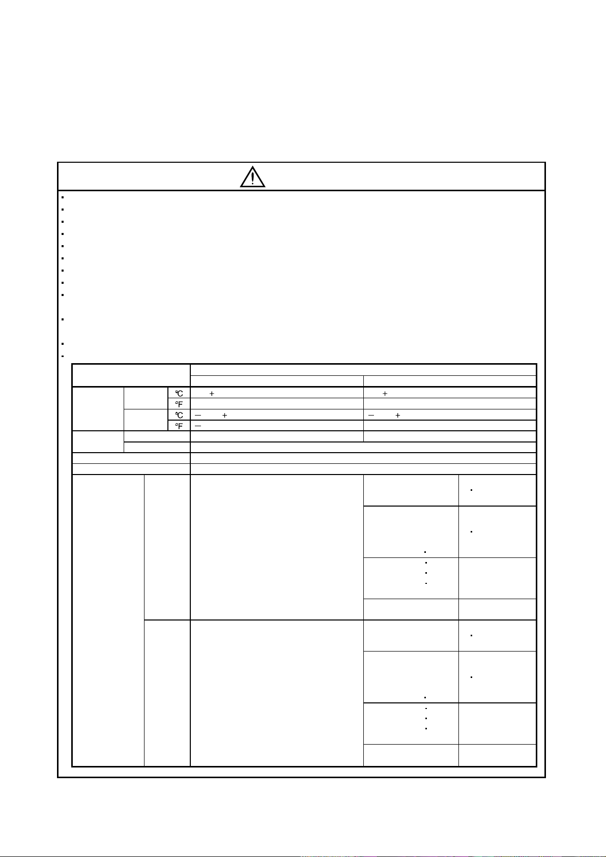
When you keep or use it, please fulfill the following environmental conditions.
Environment
Ambient
temperature
Ambient
humidity
Ambience Indoors (no direct sunlight) Free from corrosive gas, flammable gas, oil mist, dust and dirt
Altitude Max. 1000m (3280 ft) above sea level
(Note)
Vibration
Note. Except the servo motor with reduction gear.
Operation
Storage
Operation 90%RH or less (non-condensing) 80%RH or less (non-condensing)
Storage 90%RH or less (non-condensing)
[ ]0 to 55 (non-freezing) 0 to 40 (non-freezing)
[
] 32 to 131 (non-freezing) 32 to 104 (non-freezing)
[ ] 20 to 65 (non-freezing) 15 to 70 (non-freezing)
[
] 4 to 149 (non-freezing) 5 to 158 (non-freezing)
[m/s2] 5.9 or less
2
] 19.4 or less
[ft/s
Servo amplifier Servo motor
Conditions
HC-KFS Series
HC-MFS Series
HC-UFS13 to 73
HC-SFS81
HC-SFS52 to 152
HC-SFS53 to 153
HC-RFS Series
HC-UFS 72
HC-SFS121 201
HC-SFS202
HC-SFS203
HC-UFS202
HC-SFS301
HC-KFS Series
HC-MFS Series
HC-UFS 13 to 73
HC-SFS81
HC-SFS52 to 152
HC-SFS53 to 153
HC-RFS Series
HC-UFS 72
HC-SFS121 201
HC-SFS202
HC-SFS203
HC-UFS202
HC-SFS301
152
352
353
152
352
353
X
Y : 49
Y : 24.5
X
X : 24.5
Y : 49
X : 24.5
Y : 29.4
X
Y : 161
Y : 80
X
X : 80
Y : 161
X : 80
Y : 96
A - 3
Page 5
CAUTION
Securely attach the servo motor to the machine. If attach insecurely, the servo motor may come off during
operation.
The servo motor with reduction gear must be installed in the specified direction to prevent oil leakage.
For safety of personnel, always cover rotating and moving parts.
Never hit the servo motor or shaft, especially when coupling the servo motor to the machine. The encoder
may become faulty.
Do not subject the servo motor shaft to more than the permissible load. Otherwise, the shaft may break.
When the equipment has been stored for an extended period of time, consult Mitsubishi.
(2) Wiring
CAUTION
Wire the equipment correctly and securely. Otherwise, the servo motor may misoperate.
Do not install a power capacitor, surge absorber or radio noise filter (FR-BIF option) between the servo
motor and servo amplifier.
Connect the output terminals (U, V, W) correctly. Otherwise, the servo motor will operate improperly.
Do not connect AC power directly to the servo motor. Otherwise, a fault may occur.
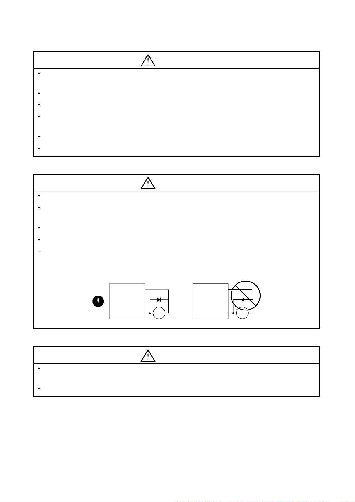
The surge absorbi ng diode in stal le d on th e D C out pu t si gnal r el ay must be wi red in th e spe ci fie d di re ctio n .
Otherwise, the forced stop (EMG) and other protective circuits may not operate.
Servo
amplifier
(24VDC)
Control
output
signal
COM
RA
Servo
amplifier
(24VDC)
Control
output
signal
COM
RA
(3) Test run adjustment
CAUTION
Before operation, check the parameter settings. Improper settings may cause some machines to perform
unexpected operation.
The parameter settings must not be changed excessively. Operation will be insatiable.
A - 4
Page 6
(4) Usage
CAUTION
Provide an exter nal emergenc y stop circuit to ensure that operatio n can be sto pped and power switc hed
off immediately.
Any person who is involved in disassembly and repair should be fully competent to do the work.
Before resett ing an alarm , m ake sure that th e run s ignal is off to pre vent an accid ent. A su dden restar t is
made if an alarm is reset with the run signal on.
Do not modify the equipment.
Use a noise fi lter , etc. to minimize th e inf lue nce of elec trom ag netic int erf erenc e, wh ich m a y b e c ause d b y
electronic equipment used near the servo amplifier.
Use the servo amplifier with the specified servo motor.
The electromagnetic brake on the servo motor is designed to hold the motor shaft and should not be used
for ordinary braking.
For such reasons as service life and mechanical structure (e.g. where a ballscrew and the servo motor are
coupled via a timing belt), the electromagnetic brake may not hold the motor shaft. To ensure safety,
install a stoppe r on the machin e si de.
(5) Corrective actions
CAUTION
When it is assum ed that a hazardous condi tion may take p lace at the occ ur due to a p ower failure or a
product fault, use a servo motor with electromagnetic brake or an external brake mechanism for the
purpose of prev en ti on .
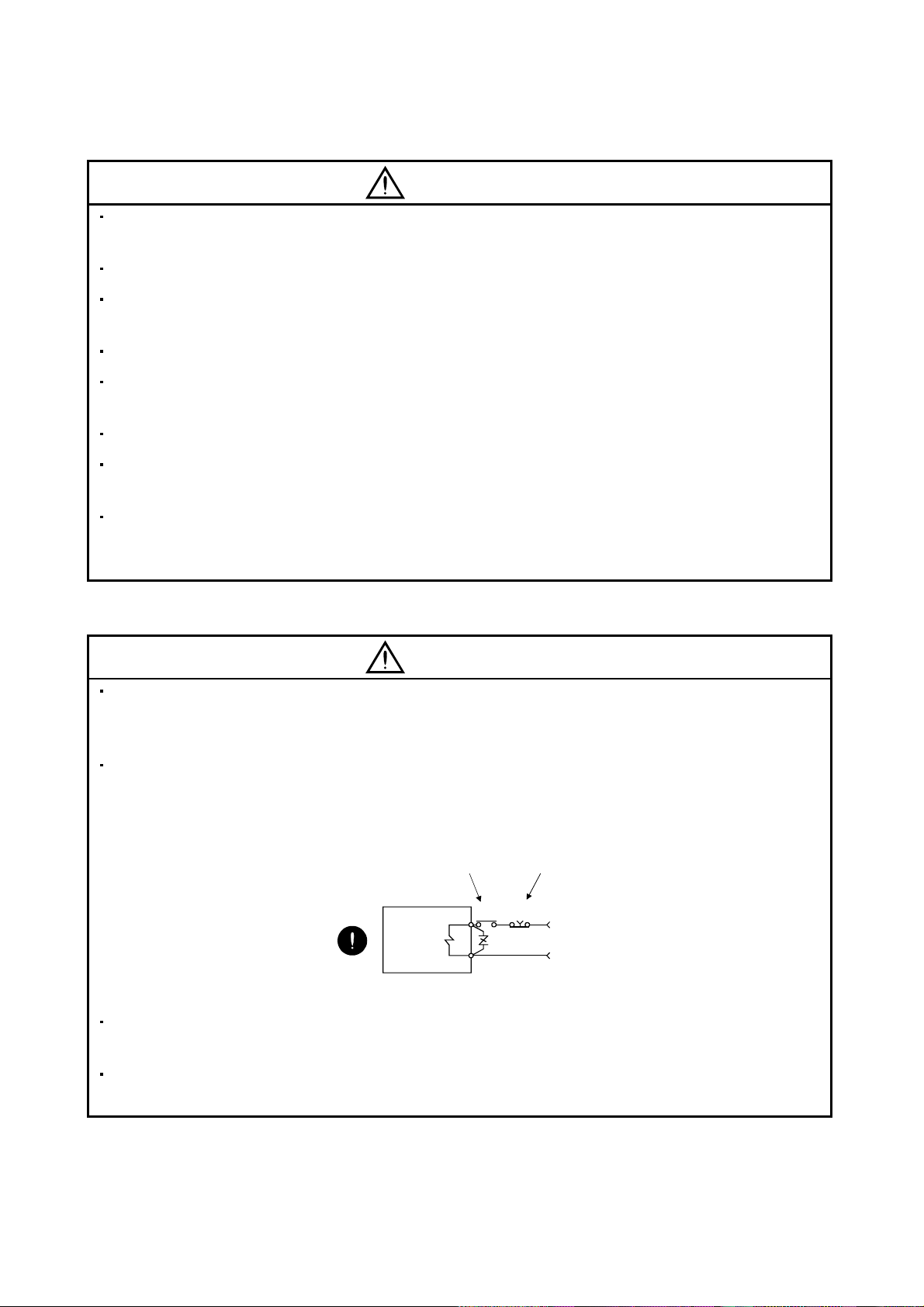
Configure the electromagnetic brake circuit so that it is activated not only by the servo amplifier signals but
also by an exte rnal fo r ced st op (EMG ).
Contacts must be open when
servo-on (SON) is off, when a trouble (ALM)
is present and when an electromagnetic
brake interlock (MBR).
Servo motor
Electromagnetic brake
When any alarm has occurred, eliminate its cause, ensure safety, and deactivate the alarm before
restarting operation.
Circuit must be
opened during
forced stop (EMG).
EMGRA
24VDC
When power is restor ed after an insta ntaneous power fail ure, keep a way from the m achine beca use the
machine may be restarted suddenly (design the machine so that it is secured against hazard if restarted).
A - 5
Page 7
(6) Maintenance, inspection and parts replacement
CAUTION
With age, the electrolytic capacitor will deteriorate. To prevent a secondary accident due to a fault, it is
recommended to replace the electrolytic capacitor every 10 years when used in general environment.
Please consult our sales representative.
(7) General instruction
To illustrate de tails, the equipment in the diagrams of this Sp ec if ications and I ns tr uc t io n Ma nual may hav e
been drawn withou t covers and safety guards. W hen the equipment is operated, the covers and safety
guards must be installed as specified. Operation must be performed in accordance with this Specifications
and Instruction Manual.
About processing of waste
When you discard servo amplifier, a battery (primary battery), and other option articles, please follow the law of
each country (area).
FOR MAXIMUM SAFETY
This product is not designed or manufactured to be used in equipment or systems in situations that can
affect or enda nge r hu man li fe .
When considering this product for operation in special applications such as machinery or systems used in
passenger transportation, medical, aerospace, atomic power, electric power, or submarine repeating
applications, please contact your nearest Mitsubishi sales representative.
Although this product was manufactured under conditions of strict quality control, you are strongly advised
to install safety devices to forestall serious accidents when it is used in facilities where a breakdown in the
product is likely to cause a serious accident.
EEP-ROM life
The number of write times to the EEP-ROM, which stores parameter settings, etc., is limited to 100,000. If
the total number of the following operations exceeds 100,000, the servo amplifier and/or converter unit may
fail when the EEP-ROM reaches the end of its useful life.
Write to the EEP-R OM du e to pa ra met er se t ting ch an ge s
Home position setting in the absolute position detection system
Write to the EEP-ROM due to device changes
Write to the EEP-ROM due to program changes
A - 6
Page 8

COMPLIANCE WITH EC DIRECTIVES
1. WHAT ARE EC DIRE C TIVES ?
The EC directives were issued to standardize the regulations of the EU countries and ensure smooth
distribution of safety-guaranteed products. In the EU countries, the machinery directive (effective in
January, 1995), EMC directive (effective in January, 1996) and low voltage directive (effective in January,
1997) of the EC directives require that products to be sold should meet their fundamental safety
requirements and carry the CE marks (CE mar king). CE marking applies to machines and equipment
into which servo amplifiers have been installed.
(1) EMC directive
The EMC directive applies not to the servo units alone but to servo-incorporated machines and
equipment. This requires the EMC filters to be used with the servo-incorporated machines and
equipment to comply with the EMC directive. For specific EMC directive conforming methods, refer to
the EMC Installation Guidelines (IB(NA)67310).
(2) Low voltage di re ctiv e
The low voltage directive applies also to servo units alone. Hence, they are designed to comply with
the low voltage directive.
This servo is certified by TUV, third-party assessment orga nization, to comply with the low voltage
directive.
(3) Machine directive
Not being machines, the servo amplifiers need not comply with this directive.
2. PRECAUTIONS FOR COMPLIANCE
(1) Servo amplifiers and servo motors used
Use the servo amplifiers and servo motors which comply with the standard model.
Servo amplifier series :MR-J2S-10CL to MR-J2S-700CL
MR-J2S-10CL1 to MR-J2S40CL1
Servo motor series :HC-KFS
HC-MFS
HC-SFS
HC-RFS
HC-UFS
HA-LFS
HC-LFS
(2) Configuration
Control box
Reinforced
insulating type
Reinforced
insulating
transformer
No-fuse
breaker
NFB
Magnetic
contactor
MC
24VDC
power
supply
Servo
amplifier
Servo
motor
SM
(3) Environment
Operate the servo amplifier at or above the contamination level 2 set forth in IEC664. For this
purpose, install the servo amplifier in a control box which is protected against water, oil, carbon, dust,
dirt, etc. (IP54).
A - 7
Page 9
(4) Power supply
(a) Operate the servo amplifier to meet the requirements of the overvoltage category II set forth in
IEC664. For this purpose, a reinforced insulating transformer conforming to the IEC or EN
Standard should be used in the power input section.
(b) When supplying interface power from external, use a 24VDC power supply which has been
insulation-reinforced in I/O.
(5) Grounding
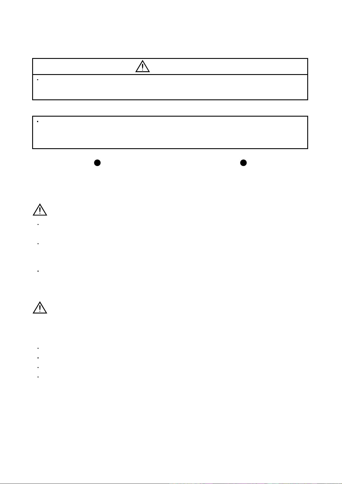
(a) To prevent an electric shock, always connect the protective earth (PE) terminals (marked
servo amplifier to the protective earth (PE) of the control box.
(b) Do not connect two ground cables to the same protective earth (PE) terminal. Always connect the
cables to the terminals one-to-one.
) of the
PE terminals
PE terminals
(c) If a leakage current breaker is used to prevent an electric shock, the protective earth (PE) terminals
of the servo amplifier must be c onne ct ed t o t h e c orr es pondi n g eart h te rmi nal s.
(6) Wiring
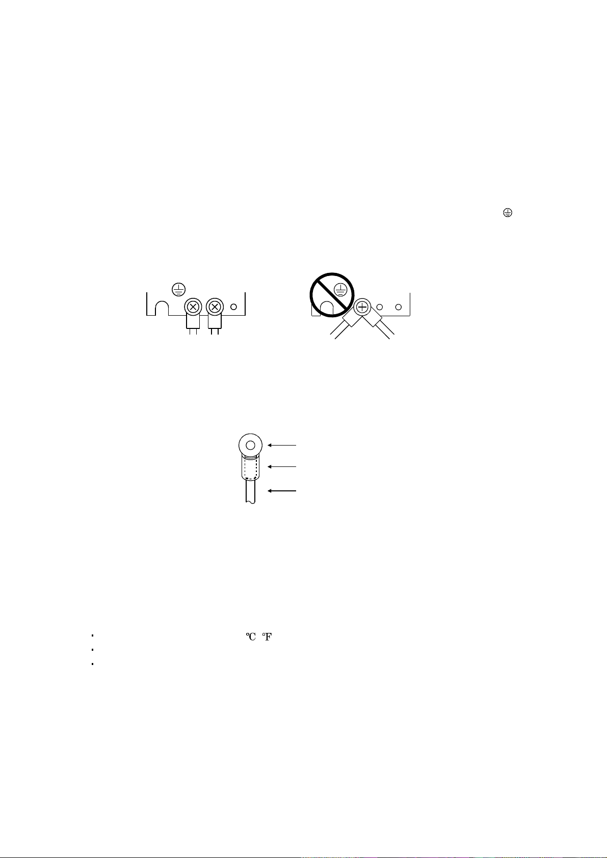
(a) The cables to be connected to the terminal block of the servo amplifier must have crimping
terminals provided with insulating tubes to prevent contact with adjacent terminals.
Crimping terminal
Insulating tube
Cable
(b) Use the servo motor side power connector which complies with the EN Standard. The EN Standard
compliant power connector sets are available from us as options.
(7) Auxiliary equipment and options
(a) The no-fuse breaker and magnetic contactor used should be the EN or IEC standard-compliant
products of the models described in Section 14.2.2.
(b) The sizes of the cable s described in Section 14.2. 1 meet the following req uirements. To meet t he
other requirements, follow Table 5 and Appendix C in EN60204-1.
Ambient tempera t ur e: 40 (104 ) [ ( )]
Sheath: PVC (polyvinyl chloride)
Installed on wall surface or open table tray
(c) Use the EMC filter for noise reduction.
(8) Performing EMC tests
When EMC tests are ru n on a machine/device in to which the servo amplifier has been installed, i t
must conform to the electromagnetic compatibility (immunity/emission) standards after it has
satisfied the operating environment/electrical equipment specificati ons.
For the other EMC directive guidelines on the servo amplifier, refer to the EMC Installation
Guidelines(IB(NA)67310).
A - 8
Page 10
CONFORMANCE WITH UL/C-UL STANDARD
(1) Servo amplifiers and servo motors used
Use the servo amplifiers and servo motors which comply with the standard model.
Servo amplifier series :MR-J2S-10CL to MR-J2S-700CL
MR-J2S-10CL1 to MR-J2S-40CL1
Servo motor series :HC-KFS
HC-MFS
HC-SFS
HC-RFS
HC-UFS
HA-LFS
HC-LFS
(2) Installation
Install a fan of 100 CFM (2.8m
cooling of at least equivalent capability.
(3) Short circuit rating
This servo amplifier conforms to the circuit whose peak current is limited to 5000A or less. Having
been subjected to the short-circuit tests of the UL in the alternating-current circuit, the servo
amplifier conforms to the above circuit.
(4) Capacitor discharge time
The capacitor disc har ge tim e is a s listed belo w. To ensu re safety , do no t touch th e ch arg ing sec tion for
10 minutes after power-off.
3
/min) air f low 4 [in] (10.16 [ cm]) above the servo amplifier or p rovide
Servo amplifier Discharge time [min]
MR-J2S-10CL(1) 20CL(1) 1
MR-J2S-40CL(1) 60CL 2
MR-J2S-70CL to 350CL 3
MR-J2S-500CL 700CL 5
(5) Options and auxiliary equipment
Use UL/C-UL standard-compliant products.
(6) Attachment of a servo motor
For the flange size of the machine side where the servo motor is installed, refer to “CONFORMANCE
WITH UL/C-UL STANDARD” in the Servo Motor Instruction Manual.
(7) About wiring protection
For installation in United States, branch circuit protection must be provided, in accordance with the
National Electrical Code and any applicable local codes.
For installation in Canada, branch circuit protection must be provided, in accordance with the Canada
Electrical Code and any applicable provincial codes.
<<About the manual s>>
This Instruction Manua l and the MEL SERVO Se rvo Moto r Ins truc tion M anua l are re quired if yo u use
the MR-J2S-CL for the first time. Always purchase them and use the MR-J2S-CL safely.
Relevant manuals
Manual name Manual No.
MELSERVO Servo Motor Instruction Manual SH(NA)3181
EMC Installation Guidelines IB(NA)67310
A - 9
Page 11

MEMO
A - 10
Page 12

CONTENTS
1. FUNCTIONS AND CONFIGURATION 1- 1 to 1-24
1.1 Introduction.............................................................................................................................................. 1- 1
1.1.1 Function block diagram....................................................................................................................1- 2
1.1.2 System configuration........................................................................................................................1- 3
1.1.3 I/O devices .........................................................................................................................................1- 8
1.2 Servo amplifier standard specifications................................................................................................1- 9
1.3 Function list............................................................................................................................................1-11
1.4 Model code definition .............................................................................................................................1-12
1.5 Combination with servo motor..............................................................................................................1-13
1.6 Structure..................................................................................................................................................1-14
1.6.1 Part names .......................................................................................................................................1-14
1.6.2 Removal and reinstallation of the front cover ..............................................................................1-18
1.7 Servo system with auxiliary equipment...............................................................................................1-20
2. INSTALLATION 2- 1 to 2- 4
2.1 Environmental conditions.......................................................................................................................2- 1
2.2 Installation direction and clearances ....................................................................................................2- 2
2.3 Keep out foreign materials .....................................................................................................................2- 3
2.4 Cable stress..............................................................................................................................................2- 4
3. SIGNALS AND WIRING 3- 1 to 3-36
3.1 Standard connection example ................................................................................................................3- 2
3.2 Internal connection diagram of servo amplifier ...................................................................................3- 4
3.3 I/O signals................................................................................................................................................. 3- 5
3.3.1 Connectors and signal arrangements.............................................................................................3- 5
3.3.2 Signal (devices) explanations ..........................................................................................................3- 6
3.4 Detailed description of signals (devices)...............................................................................................3-13
3.4.1 Forward rotation start
3.4.2 Movement complete.........................................................................................................................3-14
3.4.3 Override............................................................................................................................................3-15
3.4.4 Torque limit......................................................................................................................................3-16
3.5 Alarm occurrence timing chart .............................................................................................................3-18
3.6 Interfaces.................................................................................................................................................3-19
3.6.1 Common line ....................................................................................................................................3-19
3.6.2 Detailed description of the interfaces............................................................................................3-20
3.7 Input power supply circuit.....................................................................................................................3-23
3.7.1 Connection example.........................................................................................................................3-23
3.7.2 Terminals..........................................................................................................................................3-25
3.7.3 Power-on sequence...........................................................................................................................3-26
3.8 Connection of servo amplifier and servo motor...................................................................................3-27
3.8.1 Connection instructions ..................................................................................................................3-27
3.8.2 Connection diagram.........................................................................................................................3-27
3.8.3 I/O terminals....................................................................................................................................3-29
Reverse rotation start Temporary stop/Restart................................ 3-13
1
Page 13

3.9 Servo motor with electromagnetic brake .............................................................................................3-31
3.10 Grounding .............................................................................................................................................3-34
3.11 Servo amplifier terminal block (TE2) wiring method.......................................................................3-35
3.12 Instructions for the 3M connector.......................................................................................................3-36
4. OPERATION 4- 1 to 4-50
4.1 When switching power on for the first time..........................................................................................4- 1
4.1.1 Pre-operation checks ........................................................................................................................4- 1
4.1.2 Startup...............................................................................................................................................4- 2
4.2 Program operation mode.........................................................................................................................4- 5
4.2.1 What is program operation mode?..................................................................................................4- 5
4.2.2 Programming language....................................................................................................................4- 6
4.2.3 Basic setting of signals and parameters........................................................................................4-25
4.2.4 Program operation timing chart ....................................................................................................4-26
4.3 Manual operation mode.........................................................................................................................4-27
4.3.1 Jog operation....................................................................................................................................4-27
4.3.2 Manual pulse generator operation.................................................................................................4-29
4.4 Manual home position return mode .....................................................................................................4-31
4.4.1 Outline of home position return.....................................................................................................4-31
4.4.2 Dog type home position return.......................................................................................................4-33
4.4.3 Count type home position return ...................................................................................................4-35
4.4.4 Data setting type home position return ........................................................................................4-36
4.4.5 Stopper type home position return ................................................................................................4-37
4.4.6 Home position ignorance (servo-on position defined as home position).....................................4-38
4.4.7 Dog type rear end reference home position return.......................................................................4-39
4.4.8 Count type front end reference home position return..................................................................4-40
4.4.9 Dog cradle type home position return ...........................................................................................4-41
4.4.10 Home position return automatic return function.......................................................................4-42
4.5 Absolute position detection system.......................................................................................................4-43
4.6 Serial communication operation ...........................................................................................................4-46
4.6.1 Positioning operation in accordance with programs....................................................................4-46
4.6.2 Multidrop system.............................................................................................................................4-46
4.6.3 Group designation............................................................................................................................4-47
4.7 Incremental value command system....................................................................................................4-49
5. PARAMETERS 5- 1 to 5-26
5.1 Parameter list..........................................................................................................................................5- 1
5.1.1 Parameter write inhibit ...................................................................................................................5- 1
5.1.2 List .....................................................................................................................................................5- 2
5.2 Detailed explanation..............................................................................................................................5-21
5.2.1 Electronic gear .................................................................................................................................5-21
5.2.2 Changing the status display screen...............................................................................................5-22
5.2.3 S-pattern acceleration/deceleration...............................................................................................5-23
5.2.4 Analog output...................................................................................................................................5-23
5.2.5 Changing the stop pattern using a limit switch...........................................................................5-25
2
Page 14

5.2.6 Alarm history clear..........................................................................................................................5-25
5.2.7 Software limit...................................................................................................................................5-25
6. SERVO CONFIGURATION SOFTWARE 6- 1 to 6-24
6.1 Specifications ...........................................................................................................................................6- 1
6.2 System configuration...............................................................................................................................6- 1
6.3 Station setting..........................................................................................................................................6- 3
6.4 Parameters...............................................................................................................................................6- 4
6.5 Simple Program.......................................................................................................................................6- 6
6.5.1 Program data.....................................................................................................................................6- 6
6.5.2 Indirect addressing...........................................................................................................................6- 9
6.6 Device assignment method....................................................................................................................6-11
6.7 Test operation......................................................................................................................................... 6-15
6.7.1 Jog operation....................................................................................................................................6-15
6.7.2 Positioning operation.......................................................................................................................6-17
6.7.3 Motor-less operation........................................................................................................................6-19
6.7.4 Output signal (DO) forced output ..................................................................................................6-20
6.7.5 Program test operation ...................................................................................................................6-21
6.8 Alarm history ..........................................................................................................................................6-23
7. DISPLAY AND OPERATION 7- 1 to 7-20
7.1 Display flowchart..................................................................................................................................... 7- 1
7.2 Status display ..........................................................................................................................................7- 2
7.2.1 Display transition.............................................................................................................................7- 2
7.2.2 Display examples.............................................................................................................................. 7- 3
7.2.3 Status display list.............................................................................................................................7- 4
7.3 Diagnosis mode........................................................................................................................................7- 5
7.3.1 Display transition.............................................................................................................................7- 5
7.3.2 Diagnosis mode list...........................................................................................................................7- 6
7.4 Alarm mode..............................................................................................................................................7- 8
7.4.1 Display transition.............................................................................................................................7- 8
7.4.2 Alarm mode list.................................................................................................................................7- 9
7.5 Parameter mode .....................................................................................................................................7-11
7.5.1 Parameter mode transition.............................................................................................................7-11
7.5.2 Operation example...........................................................................................................................7-12
7.6 External I/O signal display....................................................................................................................7-14
7.7 Output signal (DO) forced output .........................................................................................................7-15
7.8 Test operation mode...............................................................................................................................7-16
7.8.1 Mode change.....................................................................................................................................7-16
7.8.2 Jog operation....................................................................................................................................7-17
7.8.3 Positioning operation.......................................................................................................................7-18
7.8.4 Motor-less operation........................................................................................................................7-19
3
Page 15

8. GENERAL GAIN ADJUSTMENT 8- 1 to 8-12
8.1 Different adjustment methods ...............................................................................................................8- 1
8.1.1 Adjustment on a single servo amplifier..........................................................................................8- 1
8.1.2 Adjustment using servo configuration software............................................................................8- 2
8.2 Auto tuning ..............................................................................................................................................8- 3
8.2.1 Auto tuning mode .............................................................................................................................8- 3
8.2.2 Auto tuning mode operation............................................................................................................8- 4
8.2.3 Adjustment procedure by auto tuning............................................................................................8- 5
8.2.4 Response level setting in auto tuning mode...................................................................................8- 6
8.3 Manual mode 1 (simple manual adjustment).......................................................................................8- 7
8.3.1 Operation of manual mode 1 ...........................................................................................................8- 7
8.3.2 Adjustment by manual mode 1 .......................................................................................................8- 7
8.4 Interpolation mode .................................................................................................................................8-10
8.5 Differences in auto tuning between MELSERVO-J2 and MELSERVO-J2-Super.......................... 8-11
8.5.1 Response level setting.....................................................................................................................8-11
8.5.2 Auto tuning selection....................................................................................................................... 8-11
9. SPECIAL ADJUSTMENT FUNCTIONS 9- 1 to 9-10
9.1 Function block diagram ..........................................................................................................................9- 1
9.2 Machine resonance suppression filter ...................................................................................................9- 1
9.3 Adaptive vibration suppression control.................................................................................................9- 3
9.4 Low-pass filter .........................................................................................................................................9- 4
9.5 Gain changing function...........................................................................................................................9- 5
9.5.1 Applications....................................................................................................................................... 9- 5
9.5.2 Function block diagram....................................................................................................................9- 5
9.5.3 Parameters........................................................................................................................................9- 6
9.5.4 Gain changing operation..................................................................................................................9- 8
10. INSPECTION 10- 1 to 10- 2
11. TROUBLESHOOTING 11- 1 to 11-10
11.1 Trouble at start-up ..............................................................................................................................11- 1
11.1.1 Position control mode...................................................................................................................11- 1
11.2 When alarm or warning has occurred...............................................................................................11- 2
11.2.1 Alarms and warning list ..............................................................................................................11- 2
11.2.2 Remedies for alarms.....................................................................................................................11- 3
11.2.3 Remedies for warnings.................................................................................................................11- 9
12. OUTLINE DIMENSION DRAWINGS 12- 1 to 12- 8
12.1 Servo amplifiers...................................................................................................................................12- 1
12.2 Connectors............................................................................................................................................12- 6
4
Page 16

13. CHARACTERISTICS 13- 1 to 13- 8
13.1 Overload protection characteristics...................................................................................................13- 1
13.2 Power supply equipment capacity and generated loss ....................................................................13- 2
13.3 Dynamic brake characteristics...........................................................................................................13- 4
13.4 Encoder cable flexing life....................................................................................................................13- 6
13.5 Inrush Currents at Power-On of Main Circuit and Control Circuit ..............................................13- 7
14. OPTIONS AND AUXILIARY EQUIPMENT 14- 1 to 14-44
14.1 Options..................................................................................................................................................14- 1
14.1.1 Regenerative brake options.........................................................................................................14- 1
14.1.2 Brake unit......................................................................................................................................14- 9
14.1.3 Power return converter...............................................................................................................14-11
14.1.4 Cables and connectors.................................................................................................................14-14
14.1.5 Junction terminal block (MR-TB20)..........................................................................................14-22
14.1.6 Maintenance junction card (MR-J2CN3TM) ............................................................................14-24
14.1.7 External digital display (MR-DP60)..........................................................................................14-26
14.1.8 Manual pulse generator (MR-HDP01) ......................................................................................14-28
14.1.9 Battery (MR-BAT, A6BAT).........................................................................................................14-29
14.2 Auxiliary equipment ..........................................................................................................................14-30
14.2.1 Recommended wires....................................................................................................................14-30
14.2.2 No-fuse breakers, fuses, magnetic contactors...........................................................................14-32
14.2.3 Power factor improving reactors................................................................................................14-32
14.2.4 Relays............................................................................................................................................14-33
14.2.5 Surge absorbers ...........................................................................................................................14-33
14.2.6 Noise reduction techniques.........................................................................................................14-33
14.2.7 Leakage current breaker.............................................................................................................14-39
14.2.8 EMC filter.....................................................................................................................................14-41
14.2.9 Setting potentiometers for analog inputs..................................................................................14-43
15. COMMUNICATION FUNCTIONS 15- 1 to 15-36
15.1 Configuration.......................................................................................................................................15- 1
15.1.1 RS-422 configuration....................................................................................................................15- 1
15.1.2 RS-232C configuration.................................................................................................................15- 2
15.2 Communication specifications............................................................................................................15- 3
15.2.1 Communication overview.............................................................................................................15- 3
15.2.2 Parameter setting.........................................................................................................................15- 4
15.3 Protocol.................................................................................................................................................15- 5
15.4 Character codes ...................................................................................................................................15- 7
15.5 Error codes ...........................................................................................................................................15- 8
15.6 Checksum.............................................................................................................................................15- 8
15.7 Time-out operation..............................................................................................................................15- 9
15.8 Retry operation....................................................................................................................................15- 9
15.9 Initialization........................................................................................................................................15-10
15.10 Communication procedure example ...............................................................................................15-10
5
Page 17

15.11 Command and data No. list.............................................................................................................15-11
15.11.1 Read commands.........................................................................................................................15-11
15.11.2 Write commands........................................................................................................................15-14
15.12 Detailed explanations of commands...............................................................................................15-16
15.12.1 Data processing..........................................................................................................................15-16
15.12.2 Status display ............................................................................................................................15-18
15.12.3 Parameter...................................................................................................................................15-19
15.12.4 External I/O signal statuses.....................................................................................................15-21
15.12.5 Device ON/OFF..........................................................................................................................15-23
15.12.6 Disable/enable of I/O devices (DIO) .........................................................................................15-24
15.12.7 Input devices ON/OFF (test operation)...................................................................................15-25
15.12.8 Test operation mode..................................................................................................................15-26
15.12.9 Output signal pin ON/OFF output signal (DO) forced output..............................................15-29
15.12.10 Alarm history...........................................................................................................................15-30
15.12.11 Current alarm..........................................................................................................................15-31
15.12.12 Current position latch data ....................................................................................................15-32
15.12.13 General-purpose register ........................................................................................................15-33
15.12.14 Servo amplifier group designation.........................................................................................15-35
15.12.15 Software version......................................................................................................................15-36
Appendix App- 1 to App- 2
App 1. Status indication block diagram .................................................................................................App- 1
App 2. Junction terminal block (MR-TB20) terminal block labels...................................................... App- 2
6
Page 18

Optional Servo Motor Instruction Manual CONTENTS
The rough table of contents of the optional MELSERVO Servo Motor Instruction Manual is in troduced
here for your reference. Note that the contents of the Servo Motor Instruction Manual are not included in
the Servo Amplifier Instruction Manual.
1. INTRODUCTION
2. INSTALLATION
3. CONNECTORS USED FOR SERVO MOTOR WIRING
4. INSPECTION
5. SPECIFICATIONS
6. CHARACTERISTICS
7. OUTLINE DIMENSION DRAWINGS
8. CALCULA TI ON ME TH O DS F OR DES I G NI N G
7
Page 19

MEMO
8
Page 20

1. FUNCTIONS AND CONFIGURATION
1. FUNCTIONS AND CONFIGURATION
1.1 Introduction
The MR-J2S-CL prog ram-compatible AC servo amplifie r is based on the MR-J2S-C P AC servo amplifier
with built-in positioning functions and incorporates program-driven, single-axis positioning functions.
These functions perform positioning operation by creating the position data (target positions), servo motor
speeds, acceleration and deceleration time constants, etc. as a program and executing the program. The
servo amplifie r is the mos t appropriate to config ure a simple positioning system o r to sim plify a system,
for example.
Up to 16 programs can be created. The program capacity is 120 steps as a total of all programs.
All servo motors are equipped with an absolute position encoder as standard. An absolute position
detection system can be configured by merely adding a battery to the servo amplifier. Once the home
position has been set, home position return is not required at power on, alarm occurrence, etc.
1 - 1
Page 21
1. FUNCTIONS AND CONFIGURATION
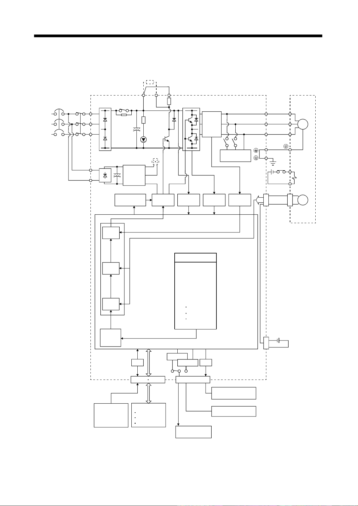
1.1.1 Function block diagram
The function block diagram of this servo is shown below.
Regenerative brake option
(Note3)
(Note2)
Power
supply
3-phase
200 to
230VAC,
or
1-phase
100 to
120VAC
NFB
MC
Servo amplifier
DS
1
L
2
L
3
L
RA
(MR-J2S-200CP or more)
11
L
21
L
Control
power
supply
PDC
Regenerative
brake
transistor
CHARGE
lamp
Fan
(Note1)
Current
detector
Dynamic
brake
Servo motor
U
U
V
V
SM
W
W
E1
Electromagnetic
E2
brake
Current
control
Speed
control
Model adaptive control
Position
control
Position
command
creation
Regenerative
brake
A/D
CN1A CN1B
Base
amplifier
I/F
Voltage
detection
SPN (1000)
STA (200)
STB (300)
MOV (500)
SPN (1000)
MOVA (1000)
MOVA (0)
STOP
RS-232C
RS-422
Program
CN3
Overcurrent
protection
D/A
Current
detection
CN2
Encoder
MR-BAT
CON1
Optional battery
(for absolute position
detection system)
Controller
RS-422/RS-232C
Analog
(2 channels)
D I/O control
Servo on
Start
Failure, etc.
To other servo
amplifier
Note:1. The built-in regenerative brake resistor is not provided for the MR-J2S-10CL (1).
1,L2
2. For 1-phase 230VAC, connect the power supply to L
3
L
is not provided for a 1-phase 100 to120VAC power supply.
and leave L3 open.
3. For MR-J2S-350CL or less.
1 - 2
Analog monitor
(2 channels)
Page 22
1. FUNCTIONS AND CONFIGURATION
1.1.2 System configuration
This section describes operations using this servo.
You can arrange any configurations from a single-axis to max. 32-axis systems. Further, the connector
pins in the interface section allow you to assign the optimum signals to respective systems. (Refer to
Sections 1.1.3 and 3.3 .3.) The Servo configur ation Software (refe r to Chapter 6) and pe rsonal computer
are required to change or assign devices.
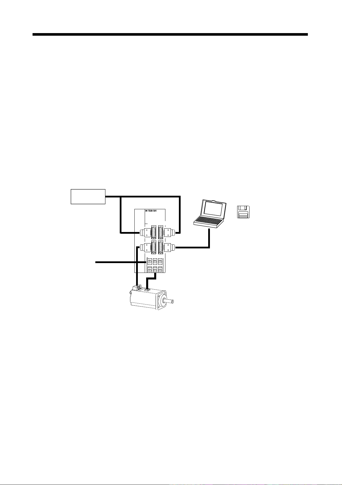
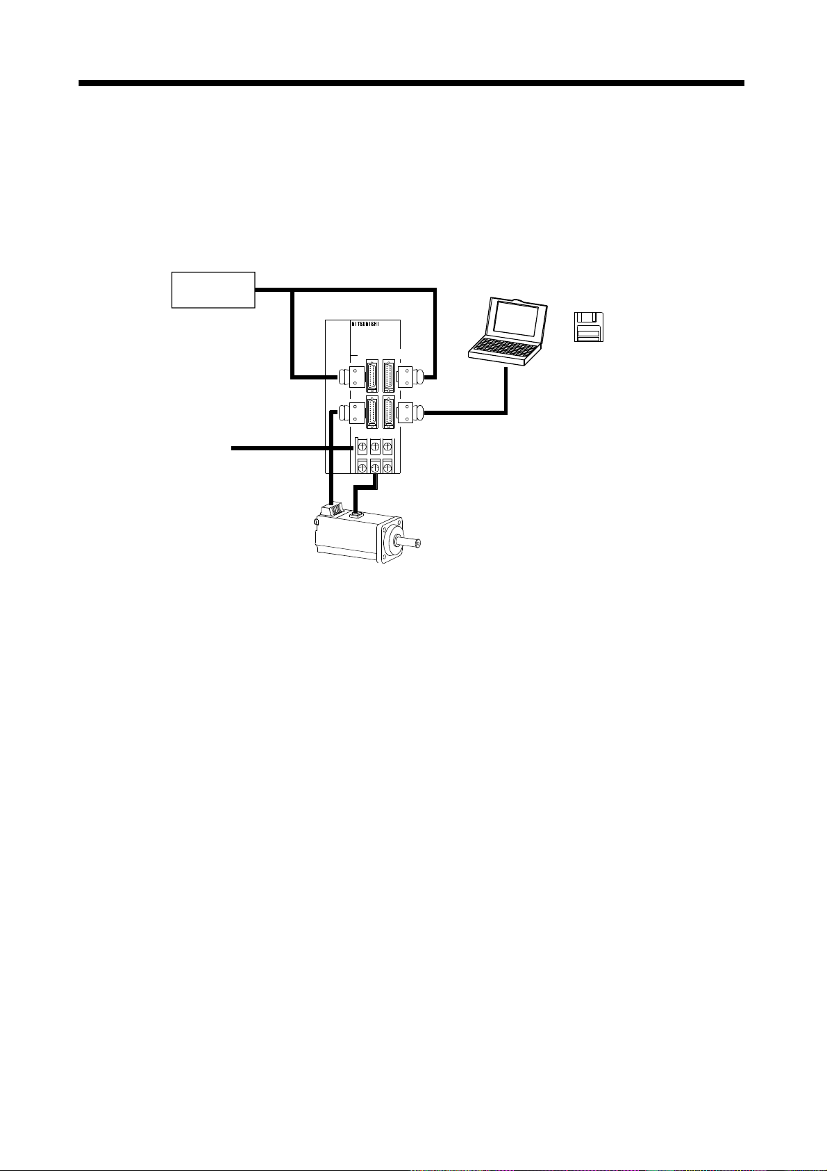
(1) Operation using external input signals
(a) Description
The following configuration example assumes that external input signals are used to control all
signals (devices).
The I/O signals are as fact or y-set.
(b) Configuration
The following configuration uses external I/O signals. The personal computer is used with Servo
configuration Software to set creation of a program, change and monitor the parameters.
External I/O
signals
Servo amplifier
Personal
computer
Servo configuration
Software
Power supply
CN1A CN1B
CN2 CN3
Servo motor
RS–232C
1 - 3
Page 23
1. FUNCTIONS AND CONFIGURATION
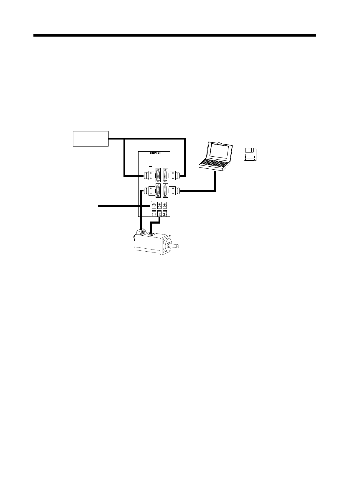
(2) Operation using external input signals and communication
(a) Description
Communication can be used to Selection of the program, change parameter values, and confirm
monitor data, for example. Enter a forward rotation start (ST1) or reverse rotation start (ST2)
through the external I/O. Use this system when position data/speed setting or the host personal
computer or the like is used to change the parameter values, for example.
(b) Configuration
1) One servo amplifier is connected with the personal computer by RS-232C.
External I/O
signals
Servo amplifier
Personal
computer
Servo configuration
Software
Power supply
CN1A CN1B
CN2 CN3
Servo motor
RS–232C
1 - 4
Page 24
1. FUNCTIONS AND CONFIGURATION
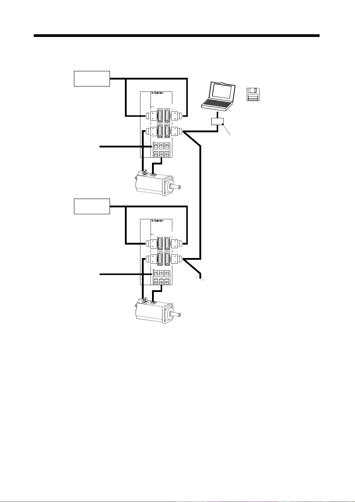
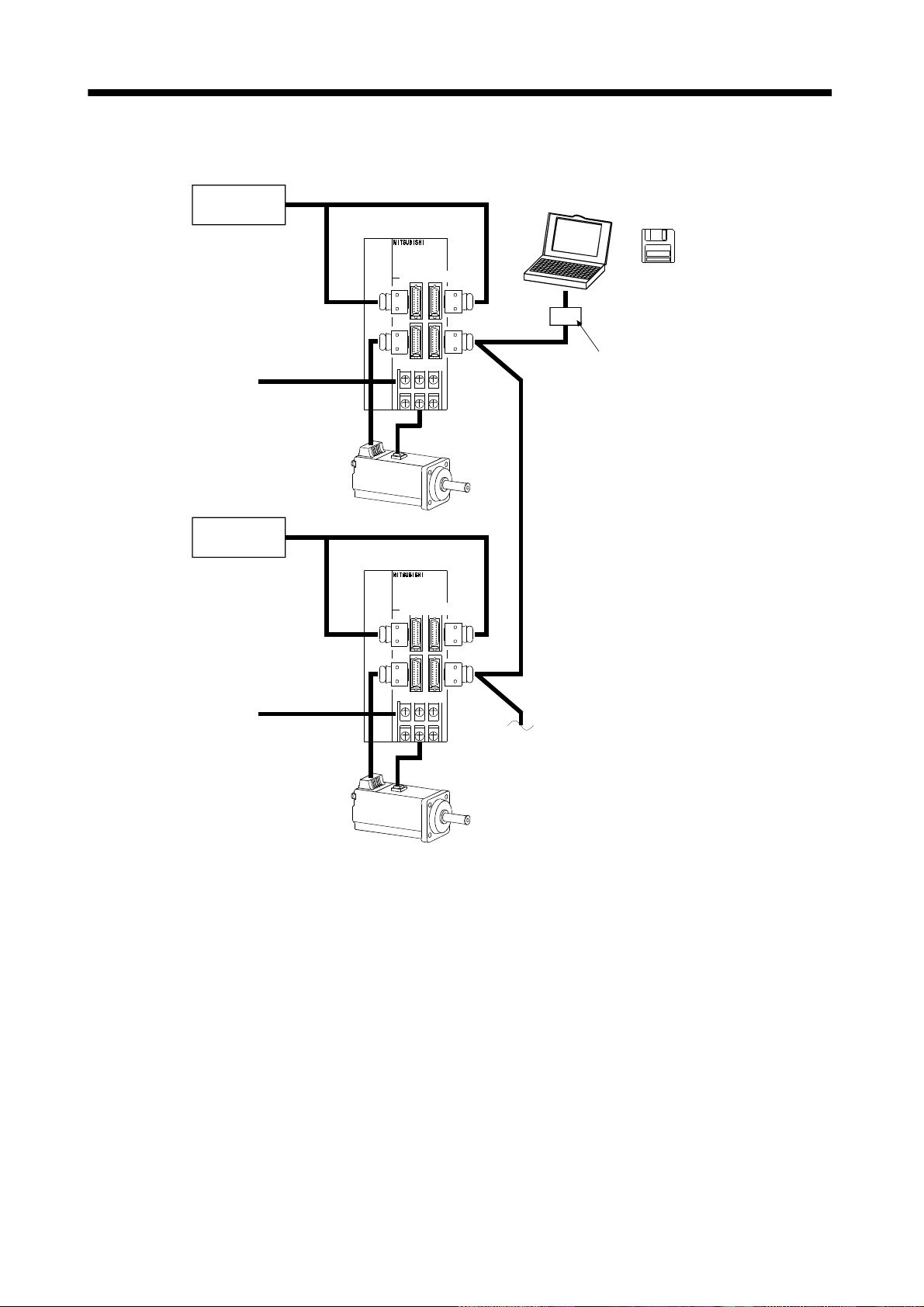
2) Several (up to 32) servo amplifiers are connected with the personal computer by RS-422.
Use parameter No. 16 to change the communication system.
External I/O
signals
Servo amplifier (axis 1)
Personal
computer
Servo configuration
Software
Power supply
External I/O
signals
Power supply
CN1A CN1B
CN2 CN3
Servo amplifier (axis 2)
CN1A CN1B
CN2 CN3
Servo motor
RS–232C
RS–422
RS–232C/RS-422 converter
(to be prepared by the customer)
RS–422
To the next axis
Servo motor
1 - 5
Page 25
1. FUNCTIONS AND CONFIGURATION
(3) Operation using communication
(a) Description
Analog input, forced s top (EMG) and other signals are controlled by exte rnal I/O signals and the
other devices controlled through communication. Also, you can set each program, selection of the
program, and change or set parameter values, for example. Up to 32 axes may be controlled.
(b) Configuration
1) One servo amplifier is connected with the personal computer by RS-232C.
External I/O
signals
Servo amplifier
Personal
computer
Servo configuration
Software
Power supply
CN1A CN1B
CN2 CN3
Servo motor
RS–232C
1 - 6
Page 26
1. FUNCTIONS AND CONFIGURATION
2) Several (up to 32) servo amplifiers are connected with the personal computer by RS-422.
Use parameter No. 16 to change the communication system.
External I/ O
signals
Servo amplifier (axis 1)
Personal
computer
Servo configuration
Software
Power supply
External I/ O
signals
Power supply
CN1A CN1B
CN2 CN3
Servo amplifier (axis 2)
CN1A CN1B
CN2 CN3
Servo motor
RS–232C
RS–422
RS–232C/RS-422 converter
(to be prepared by the customer)
RS–422
To the next axis
Servo motor
1 - 7
Page 27
1. FUNCTIONS AND CONFIGURATION
1.1.3 I/O devices
This servo amplifier allows devices to be al located to the pins of connector CN1A/CN1B as desired. The
following devices can be allocated. For device details, refer to Section 3.3.2.
Input device Symbol
Servo-on SON CN1A-19 Trouble ALM CN1B-18
Reset RES CN1B-15 Ready RD CN1B-19
Forward rotation stroke end LSP CN1B-16 Movement complete PED CN1B-6
Reverse rotation stroke end LSN CN1B-17 Zeroing completion ZP CN1A-18
Forward rotation start ST1 CN1B-7 Program output 1 OUT1 CN1B-4
Reverse rotation start ST2 Program output 2 OUT2
Proximity dog DOG CN1A-8 Program output 3 OUT3
Program No. selection 1 DI0 CN1B-5 Electromagnetic brake interlock MBR
Program No. selectio n 2 DI1 CN1B-14 Po sition range POT
Program No. select ion 3 DI2 Warning WNG
Program No. selection 4 DI3 Battery warning BWNG
Forced stop EMG Limiting torque TLC
Automatic/manual selection MD0 Temporary stop PUS
Override selection OVR SYNC synchronous output SOUT
External torque limit selection TL
Interna l torque l imit selection T L2
Proportion control PC
Temporary stop/restart STP
Manual pulse generator
multiplication 1
Manual pulse generator
multiplication 2
Gain switch CDP
Current position latch input LPS
Program input 1 PI1 CN1B-8
Program input 2 PI2 CN1B-9
Program input 3 PI3
TP0
TP1
Factory-
allocated pin
Output device Symbol
Factory-
allocated pin
1 - 8
Page 28
1. FUNCTIONS AND CONFIGURATION
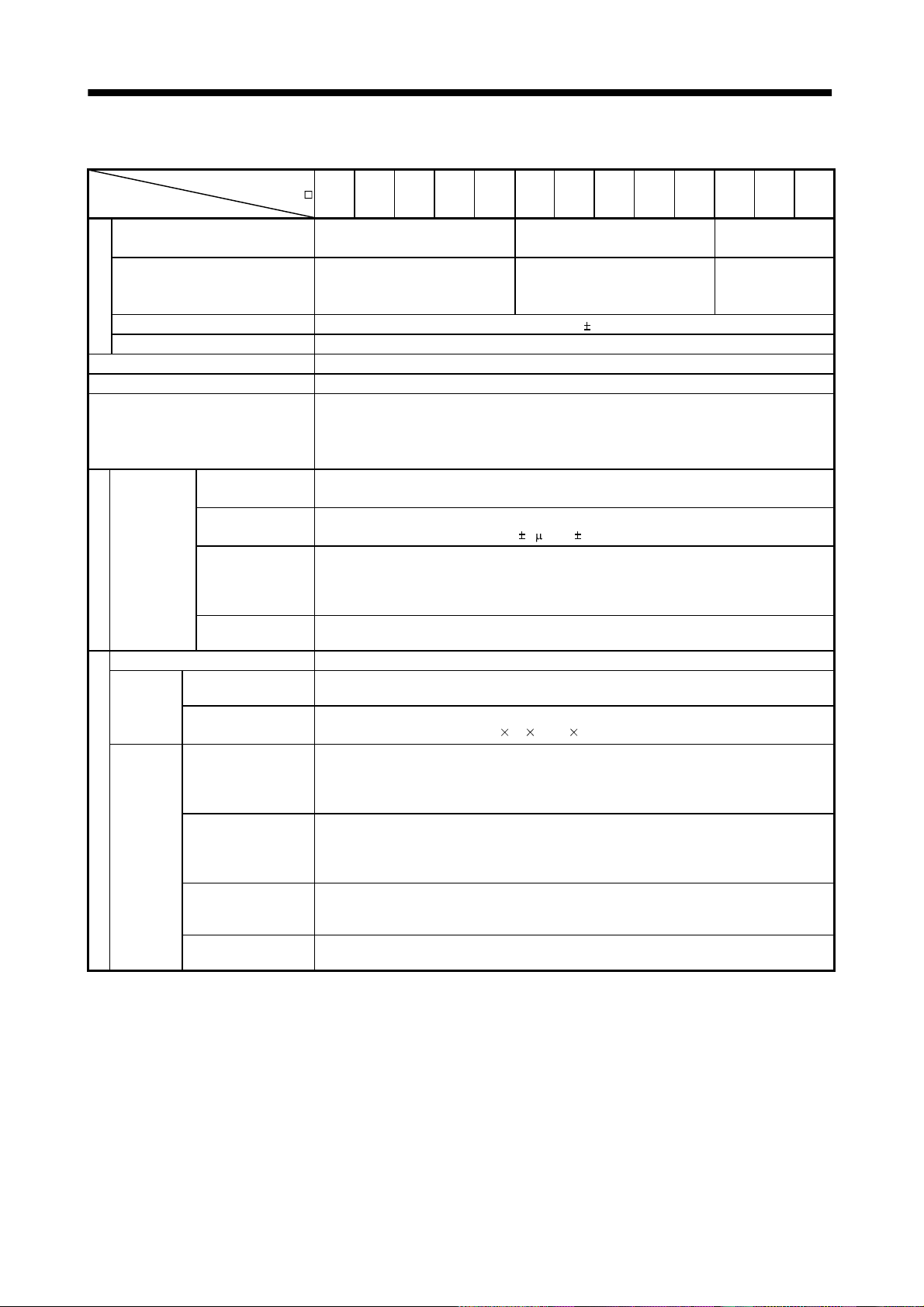
1.2 Servo amplifier standard specifications
Servo amplifier
MR-J2S-
Item
Voltage/frequency
Permissible voltage fluctuation
Power supply
Permissible frequency fluctuation Within 5%
Power supply capacity Refer to Section13.2
System Sine-wave PWM control, curr ent control system
Dynamic brake Built-in
Protective functions
Operational
specifications
Position
command input
Programming
Command system
Program operati on mode
Manual
operation
mode
Manual
home
Operation mode
position
return
mode
Speed command
input
System
Jog
Manual pulse
generator
Dog type
Count type
Data setting type
Stopper type
10CL 20CL 40CL 60CL 70CL 100CL 200CL 350CL 500CL 700CL 10CL1 20CL1 40CL1
3-phase 200 to 230VAC, 50/60Hz
or 1-phase 230VAC, 50/60Hz
3-phase 200 to 230VAC:
170 to 253VAC
1-phase 230VAC: 207 to 253VAC
Overcurrent shut-off, regenerative overvoltage shut-off, overload shut-off (electronic
thermal relay), servo motor ove rh eat protection, en cod er error protecti on, regenerative
brake error prot ect i on, undervoltag e, i ns t a nt a n e ou s power failure p rot ect ion, overspeed
protection, exces s i v e error protecti on
Programming language (Programming with Servo-configuration software).
Programming capacity: 120 steps
Setting by programming language.
Movement setting range at 1 point:
Servo motor speed , a c celeration/dec eleration time const a nt a n d S - p attern
acceleration/deceleration time con st a n t b y p rogramming lang uage.
S-pattern acceleration/decel era ti on tim e consta nt ca n set by parameter No.14 or b y
programming.
Signed absolut e v a l ue command (sig ned incremental va l u e command syste m can be
specified), signed incremental value command system
Setting by programming language
Jog operation is performed in accordance with th e p a ra meter-set speed command b y
contact input or through RS-422 (232C) communication.
Manual feed is made by manual pulse generator.
Command pulse multiplication:
Home position return is made starting with Z-phase pulse after passage of proximity dog.
Home position address may be set. Home position shift distance may be set. Home position
return direction may be selected .
Automatic at-dog home position return, Automatic stroke return function
Home position return is made by counting encoder pulses after contact with proximity dog.
Home position address may be set. Home position shift value may be set. Home position
return direction may be set.
Automatic at-dog home position return, Automatic stroke return function
Home position return is made without dog.
Home position ma y be set at any position by ma nu a l op eration, etc. H o me position address
may be set.
Home position return is ma d e by p ressing machine part against strok e e nd .
Home position address may be set. Home position return direction may be set.
3-phase 200 to 230VAC, 50/60Hz
3-phase 170 to 253VAC
1[ m] to 999.999[mm]
1, 10 or 100 is selected using parameter.
1-phase 100 to
120VAC 50/60Hz
1-phase
85 to 127VAC
1 - 9
Page 29
1. FUNCTIONS AND CONFIGURATION
Servo amplifier
MR-J2S-
Item
Home position
ignorance
10CL 20CL 40CL 60CL 70CL 100CL 200CL 350CL 500CL 700CL 10CL1 20CL1 40CL1
Position where s ervo-on (SON) i s s w i t ched on is defined as home positi on.
Home position address may be set.
(Servo-on position as
home position)
Home position return is made with respect to the rear end of a proximity dog.
Manual
home
position
return
mode
Operation mode
Dog type rear end
reference
Count type front end
reference
Home position address may be set. Home position shift value may be set. Home position
return direction may be set.
Automatic at-dog home position return, Automatic stroke return function
Home position return is made with respect to the front end of a proximity dog.
Home position address may be set. Home position shift value may be set. Home position
return direction may be set.
Automatic at-dog home position return, Automatic stroke return function
Home position return is made with respect to the front end of a proximity dog by the first
Z-phase pulse.
Dog cradle type
Home position address may be set. Home position shift value may be set. Home position
return direction may be set.
Automatic at-dog home position return, Automatic stroke return function
Absolute position detection, backlash function
Other functions
Overtravel prevention using external limit switch
Software stroke limit, override using external analog signal
Structure Self-cooled, open (I P00) Force-cooling, open (IP00 )
[ ]0 to 55 (non-freezing)
[
] 32 to 131 (non-freezing)
[ ] 20 to 65 (non-freezing)
[
] 4 to 149 (non-freezing)
90%RH or less ( non - condensing)
Indoors (no dir ect su nl i gh t )
Free from corrosive gas, flammable gas, oil mist, dust and dirt
Ambient
temperature
Ambient
humidity
Ambient
Environment
Operation
Storage
Operation
Storage
Altitude Max. 1000m (3280ft) above sea level
Vibration
Weight
5.9 [m/s2] or less
19.4 [ft/s
2
] or less
[kg] 0.7 0.7 1.1 1.1 1.7 1.7 2.0 2.0 4.9 7.2 0.7 0.7 1.1
[lb] 1.5 1.5 2.4 2.4 3.75 3.75 4.4 4.4 10.8 15.87 1.5 1.5 2.4
Self-cooled,
open (IP00)
1 - 10
Page 30

1. FUNCTIONS AND CONFIGURATION
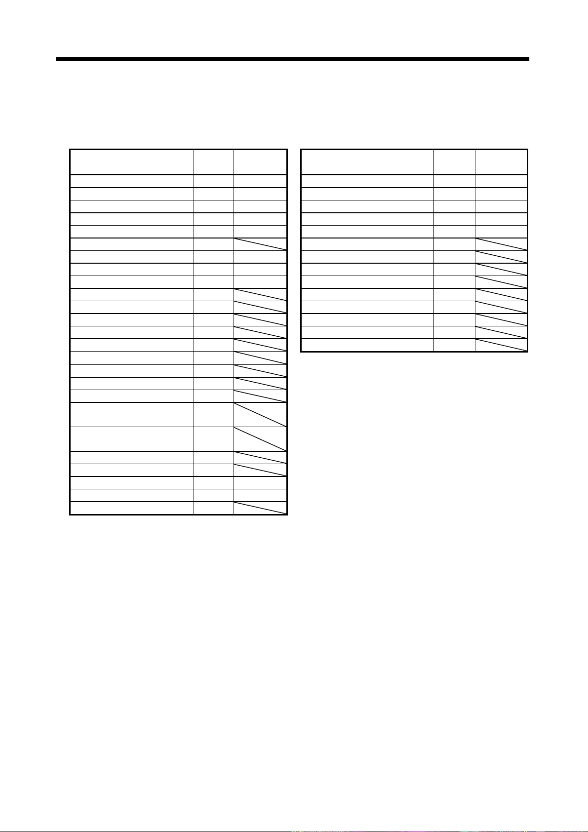
1.3 Function list
The following table lists the functions of this servo. For details of the functi ons, refer to the reference field.
Function Description Reference
Operation is performed in accordance with the contents of any
Positioning by program operation
Manual home position return
Multidrop communicati o n
High-resolut ion encoder
Absolute position detection system
Gain changing function
Adaptive vibration suppression control
Low-pass filter
Machine analyzer function
Machine simulation
Gain search function
Slight vibration suppression control Vibration of 1 pulse at servo motor stop is suppressed. Parameter No. 20
Electronic gear
Auto tuning
S-pattern acceleration/deceleration time
constant
Regenerative brake option
Brake unit
Return conv erter
program selected from among pre-created 16 programs.
Use the external input signal or communication function to choose
the program.
Dog type, count type, data setting type, stopper type, home
position ignorance, dog type rear end refere n ce, count type front
end reference, dog cradle type
Up to 32 axes of MR-J2S-CL are controllable simultaneously by
RS-422 communication.
High-resolution encoder of 131072 pulses/rev is used as a servo
motor encoder.
By merely setting the home position once, home position return
need not be done at each power on.
You can switch between gains during rotation and gains during
stop or use an external signal to change gains during operation.
Servo amplifier detects mechanical resonance and sets filter
characteristics automatically to suppress mechanical vibration.
Suppresses high-frequency resonance which occurs as servo
system response is increased.
Analyzes the frequency characteristic of the mechanical system by
simply connecting a servo configuration software-installed
personal computer and servo amplifier.
Can simulate machine motions on a personal computer screen on
the basis of the machine analyzer results.
Personal computer changes gains automatically and searches for
overshoot-free gains in a short time.
The electronic gear is used to make adjustment so that the servo
amplifier setting matches the machine moving distance. Also,
changing the electronic gear value allows the machine to be moved
at any multiplication ratio to the moving distance using the servo
amplifier.
Automatically adjusts the gain to optimum value if load applied to
the servo motor shaft varies. Higher in performance than MR-J2
series servo amplifier.
Acceleration/deceleration can be made smoothly.
Used when the bui l t-in regenera ti ve brake resis t o r of th e servo
amplifier does not have sufficient regenerative capability for the
regene rative power generat ed.
Used when the r egenerative brake option ca nnot provid e enough
regenerative power.
Can be used with the MR-J2S-500CL
Used when the regenerative brake option cannot provide enough
regenerative power.
Can be used with the MR-J2S-500CL
MR-J2S-700CL.
MR-J2S-700CL.
Section 4.2
Section 4.4
Section 4.6.3
Chapter 15
Section 4.5
Section 9.5
Section 9.3
Section 9.4
Section 5.2.1
Chapter 8
Section 4.2.1 (2) 2)
Section 5.2.3
Section 14.1.1
Section 14.1.2
Section 14.1.3
1 - 11
Page 31

1. FUNCTIONS AND CONFIGURATION
Function Description Reference
Analog monitor The servo status is output in terms of voltage in real time. Section 5.2.4
Alarm history
I/O signal selection (Device setting)
By using the Servo configura t ion Software, the current alarm an d
five past alarm numbers are stored and displayed.
By using the Servo configuration Software, any devices can be
assigned to 9 input, 5 output and 1 I/O pins.
Servo motor-torque is limited.
Torque limit
Parameter 2 limit value
Analog input
1 limit value
The servo motor speed is limited by analog input.
Override (speed limit)
The ratio of override to the set speed can be changed between 0 to
200%.
Status display The servo status is displayed. Section 7.2
Test operati on mode
Limit switch
Jog, Positioning, Operation w/o motor, Fo rc ed output, Program
test
The servo motor travel region can be limited using the forward
rotation stroke end (LSP)/reverse rotation stroke end (LSN).
The travel region is limited using parameters in terms of address.
Software limit
The function similar to that of a limit switch is limited by
parameter.
Section 6.8
Section 6.6
Section 3.2.5
Section 3.2.4
Section 6.7
Section 5.2.5
Section 5.2.9
1.4 Model code definition (1) Rating plate
MITSUBISHI
MODEL
POWER
MR-J2S-60CL
POWER :
INPUT :
OUTPUT :
SERIAL :
MITSUBISHI ELECTRIC CORPORATION
MADE IN JAPAN
600W
3.2A 3PH 1PH200-230V 50Hz
3PH 1PH200-230V 60Hz
5.5A 1PH 230V 50/60Hz
170V 0-360Hz 3.6A
A5
TC3 AAAAG52
AC SERVO
AC SERVO
PASSED
Model
Capacity
Applicable power supply
Rated output current
Serial number
1 - 12
Page 32

1. FUNCTIONS AND CONFIGURATION
(2) Model
MR–J2S–
Series
CL
Power Supply
Symbol
None
(Note1)
1
Note:1. Not supplied to the servo amplifier of
MR-J2S-60CL or more.
2. Not supplied to the servo amplifier of
MR-J2S-100CL or more.
Program compatibility operation function
Rated output
Symbol
10
20
40
60
70
Power supply
3-phase 200 to 230VAC
(Note2)
1-phase 230VAC
1-phase 100V to 120VAC
Rated
output [W]
100
200
400
600
750
1.5 Combination with servo motor
Symbol
Rated
output [W]
1000100
2000200
3500350
5000500
7000700
MR–J2S–100CL or less
Rating plate
MR-J2S-500CL
Rating plate Rating plate
MR–J2S–200CL 350CL
Rating plate
MR-J2S-700CL
The following table lists combina tion s of servo amplifie rs and se rvo mo tors. The same combina tions ap ply
to the models with electromagnetic brakes and the models with reduction gears.
Servo motors
Servo amplifier
MR-J2S-10CL (1) 053 13 053 13 13
MR-J2S-20CL (1) 23 23 23
MR-J2S-40CL (1) 43 43 43
MR-J2S-60CL 52 53
MR-J2S-70CL 73 73 72 73
MR-J2S-100CL 81 102 103
MR-J2S-200CL 121 201 152 202 153 203 103 153 152
MR-J2S-350CL 301 352 353 203 202
MR-J2S-500CL 502 353 503 352 502
MR-J2S-700CL 702
Servo amplifier
MR-J2S-60CL 52
MR-J2S-100CL 102
MR-J2S-200CL 152
MR-J2S-350CL 202
MR-J2S-500CL
MR-J2S-700CL 601 701M
Note: Consult us since the servo amplifier to be used with any of these servo motors is optional.
HC-KFS
(Note)
1000r/min
HC-MFS
Servo motors
HA-LFS
(Note)
1500r/min
1000r/min 2000r/min 3000r/min
2000r/min
(Note)
(Note)
HC-SFS HC-UFS
(Note)
HC-LFS
502 302
702
HC-RFS
2000r/min 3000r/min
1 - 13
Page 33

1. FUNCTIONS AND CONFIGURATION
1.6 Structure
1.6.1 Part names (1) MR-J2S-100CL or less
MODE
UP DOWN SET
Name/Application
Battery holder
Contains the battery for absolute positi on data back up .
Battery connector (CON1)
Used to connect the battery for absolute position data
backup.
Display
The 5-digit, seven-segment LED sho ws the ser v o
status and alarm number.
Operation section
Used to perform status display, diagnostic, alarm and
parameter sett ing op e ra ti o ns.
MODE
I/O signal connector (CN1A)
Used to connect digital I/O signals.
UP DOWN
SET
Used to set data.
Used to change the
display or data in each
mode.
Used to change the
mode.
Reference
Section4.5
Section4.5
Chapter7
Chapter7
Section3.3
I/O signal connector (CN1B)
Used to connect digital I/O signals.
Communication connector (CN3)
Used to connect a command device (RS-422/RS-232C)
and output analog monitor data.
Name plate
Charge lamp
Lit to indicate that the main circuit is charged. While
this lamp is lit, do not reconnect the cables.
Encoder connector (C N2 )
Connector for connection of the servo motor encoder.
Main circuit terminal block (TE1)
Used to connect the input power supply and servo
motor.
Control circuit terminal block (TE2)
Used to connect the co ntr o l ci rcu i t po wer supply and
regenerative brake option.
Protective earth (PE) termi nal ( )
Ground terminal.
Section3.3
Chapter6
Chapter15
Section14.1.4
Section1.4
Section3.3
Section14.1.4
Section3.7.2
Section3.7.2
Section14.1.1
Section3.10
1 - 14
Page 34

1. FUNCTIONS AND CONFIGURATION
(2) MR-J2S-200CL MR-J2S-350CL
POINT
This servo amplifier is shown without the front cover. For removal of the
front cover, refer to Section 1.6.2.
MODE UP DOWN
Name/Application
Battery holder
Contains the battery for absolute position data backup.
Battery connector (CON1)
Used to connect the battery for absolute position data
backup.
Display
The 5-digit, seven-segment LED shows the servo
status and alar m number .
Operation section
SET
Used to perform status display, diagnostic, alarm and
parameter setting operations.
DOWN
MODE
I/O signal connector (C N 1A)
Used to connect digital I/O signals.
UP
SET
Used to set data.
Used to change the
display or data in each
mode.
Used to change the
mode.
Reference
Section4.5
Section4.5
Chapter7
Chapter7
Section3.3
Cooling fan
Mounting hole (4 places)
I/O signal connector (C N 1B)
Used to connect digital I/O signals.
Communication connector (CN3)
Used to connect a command device (RS-422/RS232C)
and output analog monitor data.
Name plate
Charge lamp
Lit to indicate that the main circuit is charged. While
this lamp is lit, do not reconnect the cables.
Encoder con n e ctor (CN2)
Connector for connection of the servo motor encoder.
Main circuit terminal block (TE1)
Used to connect the input power supply and servo
motor.
Control circ ui t t e rm i nal block (TE2)
Used to connect the con t ro l ci r cuit power supply and
regenerative brake option.
Protective earth (PE) terminal ( )
Ground terminal.
Section3.3
Chapter6
Chapter15
Section14.1.4
Section1.4
Section3.3
Section14.1.4
Section3.7
Section3.7.2
Section14.1.1
Section3.10
1 - 15
Page 35

1. FUNCTIONS AND CONFIGURATION
(3) MR-J2S-500CL
POINT
The servo amplifier is shown without the front cover. For removal of the
front cover, refer to Section 1.6.2.
Battery connector (CON1)
Used to connect the battery for absolute position data
backup.
Battery holder
Contains the battery for absolute position data backup.
Display
The 5-digit, seven-segment LED shows t he se rvo
status and alar m number .
Operation section
MODE
UP DOWN SET
Used to perform status display, diagnostic, alarm and
parameter setting operations.
Name/Application Reference
Section4.5
Section4.5
Chapter7
Installation notch
(4 places)
MODE
I/O signal connector (C N 1A)
Used to connect digital I/O signals.
I/O signal connector (C N 1B)
Used to connect digital I/O signals.
Communication connector (CN3)
Used to connect a command device (RS-422/RS232C)
and output analog monitor data.
Encoder con n e ctor (CN2)
Connector for connection of the servo motor encoder.
Charge lamp
Lit to indicate that the main circuit is charged.
While this lamp is lit, do not reconnect the cables.
Control circ ui t t e rm i nal block (TE2)
Used to connect the control circuit power supply and
regenerative brake option.
UP
DOWN SET
Used to set data.
Used to change the
display or data in each
mode.
Used to change the
mode.
Chapter7
Section3.3
Section3.3
Chapter6
Chapter15
Section14.1.4
Section3.3
Section14.1.4
Section3.7.2
Section14.1.4
Cooling fan
Main circuit terminal block (TE1)
Used to connect the input power supply and servo
motor.
Name plate Section1.3
Protective earth (PE) terminal ( )
Ground terminal.
Section3.7.2
Section12.1
Section14.1.1
Section3.10
Section12.1
1 - 16
Page 36

1. FUNCTIONS AND CONFIGURATION
(4) MR-J2S-700CL
POINT
The servo amplifier is shown without the front cover. For removal of the
front cover, refer to next page.
MODE
UP DOWN
Name/Application
Reference
Battery connector (CON1)
Used to connect the battery for absolute position data
Section4.5
backup.
Battery holder
Contains the battery for absolute position data backup.
Section4.5
Display
The 5-digit, seven-segment LED shows the servo
Chapter7
status and alarm number.
Operation section
SET
Used to perform status display, diagnostic, alarm and
parameter setting operations.
MODE UP DOWN SET
Used to set data.
Chapter7
Used to change the
display or data in each
mode.
Used to change the
mode.
I/O signal conn ector (CN1A)
Used to connect digital I/O signals.
Section3.3
Cooling fan
Installation notch
(4 places)
I/O signal conn ector (CN1B)
Used to connect digital I/O signals.
Communication connector (CN3)
Used to connect a command device (RS-422/RS232C)
and output analog monitor data.
Charge lamp
Lit to indicate that the main circuit is charged.
While this lamp is lit, do not reconnect the cables.
Control circuit ter m i na l b lock (TE2)
Used to connect the control circuit power sup p ly.
Encoder conne cto r ( C N 2)
Connector for connection o f the servo motor encoder.
Name plate
Main circuit terminal block (TE1)
Used to connect the inpu t pow e r sup p ly, re ge ne ra tive
brake option and servo motor.
Protective earth (PE) terminal ( )
Ground terminal.
Section3.3
Chapter6
Chapter15
Section14.1.4
Section3.7.2
Section14.1.4
Section3.3
Section14.1.4
Section1.3
Section3.7.2
Section12.1
Section14.1.1
Section3.10
Section12.1
1 - 17
Page 37

1. FUNCTIONS AND CONFIGURATION
1.6.2 Removal and reinstallation of the front cover
CAUTION
To avoid the risk of an electric s hock, do not ope n the front co ver while power is
on.
(1) For MR-J2S-200CL or more
Removal of the front cover
1)
2)
Front cover
1) Hold down the removing knob.
2) Pull the front cover toward you.
Reinstallation of the front cover
Front cover hook
(2 places)
2)
1)
Front cover socket
(2 places)
1) Insert the front cover hooks into the front cover sockets of
the servo amplifier.
2) Press the front cover against the servo amplifier until the
removing knob clicks.
(2) For MR-J2S-500CL
Removal of the front cover
2)
Front co ve r
1) Hold down the removing knob.
2) Pull the front cover toward you.
Reinstallation of the front cover
1)
Front co ver hook
(2 places)
2)
1)
Front cover socket
(2 places)
1) Insert the front cover hooks into the front cover sockets of
the servo amplifier.
2) Press the front cover against the servo amplifier until the
removing knob clicks.
1 - 18
Page 38

1. FUNCTIONS AND CONFIGURATION
(3) For MR-J2S-700CL
Removal of the front cover
Reinstallation of the front cover
Front cover
hook
(2 places)
B)
2)
1)
A)
1) Push the removing knob A) or B), and put you
finger into the front hole of the front cover.
2) Pull the front cover toward you.
A)
2)
1)
Front cover socket
(2 places)
1) Insert the two front cover hooks at the bottom into the
sockets of the servo amplifier.
2) Press the front cover against the servo amplifier until the
removing knob clicks.
1 - 19
Page 39

1. FUNCTIONS AND CONFIGURATION
E
1.7 Servo system with auxiliar y equipm ent To prevent an electric shock, always connect the protective earth (PE) terminal
WARNING
(terminal m ar ked
box.
(1) MR-J2S-100CL or less
(a) For 3-phas e 200V t o 230V A C or 1 -p hase 23 0V A C
(Note2)
3-phase 200V
to 230VAC power
supply or
1-phase 230VAC
power supply
No-fuse breaker
(NFB) or fuse
Options and auxiliary equipment
No-fuse breaker
Magnetic contactor
Servo configuration software
Regenerative brake option
Servo amplifier
) of the servo amplifier to the prot ecti ve earth (P E) of the contr ol
Reference
Section 14.2.2
Section 14.2.2
Chapter 6
Section 14.1.1
To CN1A
Options and auxiliary equipment
Cables
Manual pulse generator
External digital display
Power factor improving reactor
Command device
Junction terminal block
Reference
Section 14.2.1
Section 14.1.8
Section 14.1.7
Section 14.2.3
Magnetic
contactor
(MC)
Power
factor
improving
reactor
(FR-BAL)
Control circuit terminal block
21
L
To CN2
1
L
2
L
3
L
U
CHARGE
VW
D
To CN1B
To CN3
Protective earth (PE) terminal
Manual pulse generator
External digital display
Personal
computer
(Note1)
Encoder cable
(Note1)
Power supply lead
Servo configuration
software
MRZJW3-SETUP151
11
L
Regenerative brake
option
Note: 1. The HC-SFS, HC-RFS, HC-UFS 2000r/min series have cannon connectors.
2. A 1-phase 230VAC power supply may be used with the servo amplifier of MR-J2S-70CL or less. Connect the power supply to
L
1
and L2 terminals and leave L3 open.
P
Servo motor
C
1 - 20
Page 40

1. FUNCTIONS AND CONFIGURATION
(b) For 1-phas e 10 0V t o 120V A C
1-phase 100V
to 120VAC
power supply
No-fuse breaker
(NFB) or fuse
Options and auxiliary equipment
No-fuse breaker
Magnetic contactor
Servo configuration so ft ware
Regenerative brake option
Servo amplifier
Reference
Section 14.2.2
Section 14.2.2
Chapter 6
Section 14.1.1
To CN1A
Options and auxiliary equipment
Cables
Manual pulse generator
External digital display
Power factor improving reactor
Command device
Junction terminal block
Reference
Section 14.2.1
Section 14.1.8
Section 14.1.7
Section 14.2.3
Magnetic
contactor
(MC)
Power
factor
improving
reactor
(FR-BAL)
Control circuit terminal block
21
L
11
L
To CN2
L1
2
L
CHARGE
UVW
D
To CN1B
External digital display
To CN3
Protective earth (PE) terminal
Manual pulse generator
Personal
computer
(Note)
Encoder cable
(Note)
Power supply lead
Servo configuration
software
MRZJW3-SETUP151E
Regenerative brake
option
P
C
Note: The HC-SFS, HC-RFS, HC-UFS 2000 r/min series have cannon connectors.
1 - 21
Servo motor
Page 41

1. FUNCTIONS AND CONFIGURATION
(2) MR-J2S-200CL MR-J2S-350CL
3-phase 200V
to 230VAC
power supply
No-fuse
breaker
(NFB) or
fuse
Magnetic
contactor
(MC)
Power
factor
improving
reactor
(FR-BAL)
Options and auxiliary equipment
No-fuse breaker
Magnetic contactor
Servo configuration software
Regenerative brake option
Servo amplifier
To CN2
11
L
21
L
Reference
Section 14.2.2
Section 14.2.2
Chapter 6
Section 14.1.1
Options and auxiliary equipment
Cables
Manual pulse generator
External digital display
Power factor improving reactor
Command device
To CN1A
To CN1B
External digital display
To CN3
Personal
computer
Reference
Section 14.2.1
Section 14.1.8
Section 14.1.7
Section 14.2.3
Junction terminal
block
Manual pulse
generator
Servo
configuration
software
MRZJW3SETUP151E
1
L
2
L
3
L
PCUVW
Regenerative brake option
1 - 22
Page 42

1. FUNCTIONS AND CONFIGURATION
(3) MR-J2S-500CL
3-phase 200V
to 230VAC
power supply
No-fuse
breaker
(NFB) or
fuse
Magnetic
contactor
(MC)
Power
factor
improving
reactor
(FR-BAL)
C
Regenerative brake option
11
L
21
L
P
Options and auxiliary equipment
No-fuse breaker
Magnetic contactor
Servo configuration software
Regenerative brake option
Servo amplifier
1
L
2
L
3
L
U
V
W
Reference
Section 14.2.2
Section 14.2.2
Chapter 6
Section 14.1.1
To CN1A
To CN1B
To CN3
To CN2
Options and auxiliary equipment
Cables
Manual pulse generator
External digital display
Power factor improving reactor
Command device
Junction terminal
block
Manual pulse
generator
External digital display
Personal
computer
Reference
Section 14.2.1
Section 14.1.8
Section 14.1.7
Section 14.2.3
Servo
configuration
software
MRZJW3SETUP151E
1 - 23
Page 43

1. FUNCTIONS AND CONFIGURATION
f
(4) MR-J2S-700CL
3-phase 200V
to 230VAC
power supply
No-fuse
breaker
(NFB) or
fuse
Magnetic
contactor
(MC)
Power
actor
improving
reactor
(FR-BAL)
Options and auxiliary equipment
No-fuse breaker
Magnetic contactor
Servo configuration software
Regenerative brake option
Reference
Section 14.2.2
Section 14.2.2
Chapter 6
Section 14.1.1
Options and auxiliary equipment
Cables
Manual pulse generator
External digital display
Power factor improving reactor
Reference
Section 14.2.1
Section 14.1.8
Section 14.1.7
Section 14.2.3
Command device
Junction terminal
block
Servo amplifier
11
L
21
L
To CN1A
Manual pulse
generator
To CN1B
External digital display
To CN3
Servo
configuration
Personal
computer
To CN2
3
L
2
L
1
L
U
V
W
software
MRZJW3-
SETUP151E
C
P
Regenerative brake option
1 - 24
Page 44

2. INSTALLATION
2. INSTALLATION
CAUTION
Stacking in excess of the limited number of products is not allowed.
Install the equipment to incombustibles. Installing them directly or close to
combustibles will led to a fire.
Install the equipment in a load-bearing place in accordance with this Instruction
Manual.
Do not get on or put heavy load on the equipment to prevent injury.
Use the equipment within the specified environmental condition range.
Provide an adequate protection to prevent screws, metallic detritus and other
conductive matter or oil and other combustible matter from entering the servo
amplifier.
Do not block the intake/exhaust ports of the servo amplifier. Otherwise, a fault may
occur.
Do not subject the servo amplifier to drop impact or shock loads as they are
precision equipment.
Do not install or operate a faulty servo amplifier.
When the product has been stored for an extended period of time, consult
Mitsubishi.
2.1 Environmental con dit ions
Environment Conditions
Ambient
temperature
Ambient
humidity
Ambience
Altitude Max. 1000m (3280 ft) above sea level
Vibration
Operation
Storage
Operation
Storage
[ ]0 to 55 (non-freezing)
] 32 to 131 (non-freezing)
[
[ ] 20 to 65 (non-freezing)
[
] 4 to 149 (non-freezing)
90%RH or less (non-condensing)
Indoors (no direct sunlight)
Free from corrosive gas, flammable gas, oil mist, dust and dirt
[m/s2] 5.9 [m/s2] or less
2
[ft/s
] 19.4 [ft/s2] or less
2 - 1
Page 45

2. INSTALLATION
2.2 Installation direction and clearances Do not hold the front cover to transport the controller. The controller may drop.
The equipment mus t be installe d in the specif ied directi on. Otherwis e, a fault may
CAUTION
(1) Installation of one servo amplifier
10mm
(0.4 in.)
or more
occur.
Leave specified clearances between the servo amplifier and control box inside
walls or other equipment.
Control box Control box
40mm
(1.6 in.)
or more
Servo amplifier
10mm
(0.4 in.)
or more
Wiring clearance
70mm
(2.8 in.)
Up
40mm
(1.6 in.)
or more
Down
2 - 2
Page 46

2. INSTALLATION
(2) Installation of two or more servo amplifiers
Leave a large clearance between the top of the servo amplifier and the internal surface of the control
box, and install a fan to prevent the internal temperature of the control box from exceeding the
environmental conditions.
Control box
100mm
(4.0 in.)
or more
30mm
(1.2 in.)
or more
40mm
(1.6 in.)
or more
10mm
(0.4 in.)
or more
30mm
(1.2 in.)
or more
(3) Others
When using heat generating equipment such as the regenerative brake option, install them with full
consideration of heat generation so that the servo amplifier is not affected.
Install the servo amplifier on a perpendicular wall in the correct vertical direction.
2.3 Keep out foreign materials
(1) When installin g the unit in a control box, prevent drill ch ips and wire fragmen ts from entering the
servo amplifier.
(2) Prevent oil, water, metallic dust, etc. from entering the servo amplifier through openings in the control
box or a fan installed on the ceiling.
(3) When insta lling the co ntrol box in a place whe re there are much toxic g as, dirt and dust, conduct an
air purge (force clean air into the contro l box from outside to make the internal pressure higher than
the external pressure) to prevent such materials from entering the control box.
2 - 3
Page 47

2. INSTALLATION
2.4 Cable stress
(1) The way of clamping the cable must be fully examined so that flexing stress and cable's own weight
stress are not applied to the cable connection.
(2) For use in any application where the servo motor moves, fix the cables (encoder, power supply, brake)
supplied with the servo motor, and flex the optional encoder cable or the power supply and brake
wiring cables. Use the optional encoder cable within the flexing life range. Use the power supply and
brake wiring cables within the flexing li fe of the cabl es.
(3) Avoid any probability that the cable sheath might be cut by sharp chips, rubbed by a machine corner
or stamped by workers or vehicles.
(4) The flexing lives of the cables are shown below. In actuality, provide a little allowance for these values.
For installation on a machine where the servo motor will move, the flexing radius should be made as
large as possible. Refer to Section 13.4 for the flexing life.
2 - 4
Page 48

3. SIGNALS AND WIRING
3. SIGNALS AND WIRING
Any person who is involved in wiring should be fully competent to do the work.
Before starting wiring, switch power off, then wait for more than 10 minutes, and
after the charge lamp has gone off, make sure that the voltage is safe in the tester
or like. Otherwise, you may get an electric shock.
WARNING
CAUTION
Ground the servo amplifier and the servo motor securely.
Do not attempt to wire the servo amplifier and servo motor until they have been
installed. Otherwise, you may get an electric shock.
The cables should not be damaged, stressed excessively, loaded heavily, or
pinched. Otherwise, you may get an electric shock.
Wire the equipment correctly and securely. Otherwise, the servo motor may
misoperate, resulting in injury.
Connect cables to correct terminals to prevent a burst, fault, etc.
Ensure that polarity ( , ) is correct. Otherwise, a burst, damage, etc. may occur.
The surge absorbing diode installed to the DC relay designed for control output
should be fitted in the specified direction. Otherwise, the signal is not output due to
a fault, disabling the forced stop (EMG) and other protective circuits.
Servo
amplifier
(24VDC)
Control
output
signal
COM
RA
Servo amplifier
COM
(24VDC)
Control output
signal
RA
Use a noise filter, etc. to minimize the influence of electromagnetic interference,
which may be given to electronic equipment used near the servo amplifier.
Do not install a power capacitor, surge suppressor or radio noise filter (FR-BIF
option) with the power line of the servo motor.
When using the regenerative brake resistor, switch power off with the alarm signal.
Otherwise, a transistor fault or the like may overheat the regenerative brake
resistor, causing a fire.
Do not modify the equipment.
POINT
CN1A, CN1B, CN2 and CN3 have the same shape. Wrong connection of
the connectors will lead to a failure. Connect them correctly.
3 - 1
Page 49

3. SIGNALS AND WIRING
3.1 Standard connection example
Proximity dog
Servo-on
10m (32.79ft.) or less
Forward rotation stroke end
(Note 5)
Reverse rotation stroke end
Program input 1
Program input 2
Forward rotation start
Program No. selection 1
Program No. selection 2
Reset
Upper limit setting
(Note 8)
(Note 9) Analog torque limit
(Note 11)
Servo Configuration
software
Override
Upper limit setting
Personal
computer
DOG
SON
SG
LSP
LSN
PI2
ST1
DI0
DI1
RST
SG
P15R
VC
LG
TLA
SD
2m (6.56ft.) or less
(Note 10)
Communication cable
Servo amplifier
(Note 3, 7)(Note 3, 7)
CN1A
8
19
10
CN1A
9
18
(Note 3, 7) (Note 3, 7)
CN1B
16
17
8PI1
9
7
5
14
15
10
11
2
CN1B
3
13
4
6
18
19
(Note 3, 7)
CN1B
6LA
16 LAR
7LB
1
17 LBR
5LZ
12
15 LZR
Plate
Plate
(Note 3, 7)
CN3
4
3
14
13
CN3
Plate
COM
ZP
VDD
COM
OUT1
PED
ALM
RD
SD
MO1
LG
MO2
LG
SD
2m (6.56ft.) or less
(Note 2, 4)
RA5
(Note 2, 4)
RA1
RA2
RA3
RA4
Home position
return completion
Program output 1
Movement
complete
Trouble (Note 6)
Ready
Encoder A-phase pulse
(differential line driver)
Encoder B-phase pulse
(differential line driver)
Encoder Z-phase pulse
(differential line driver)
A
10k
(Note 10)
Monitor output
Max. 1mA
A
10k
meter
Zero center
3 - 2
(Note 1)
Page 50

3. SIGNALS AND WIRING
Note: 1. To prevent an electric shock, always connect the protective earth (PE) terminal of t he servo amplifier to the protective earth
(PE) of the co ntrol bo x.
2. Connect the diode in the correct direction. If it is connected reversely, the servo amplifier will be faulty and will not output
signals, disabling the emergency stop and other protective circuits.
3. CN1A, CN1B, CN2 and CN3 have the same shape. Wrong connection of the connectors will lead to a fault.
4. The sum of currents that flow in the external relays should be 80mA max. If it exceeds 80mA, supply interface power from
external.
5. When starting operation, always connect the forward/reverse rotation st roke end (LSN/LSP) with SG. (Normally closed
contacts)
6. Trouble (ALM) is connected with COM in normal alarm-free condition.
7. The pins with the same signal name are connected in the servo amplifier.
8. When using override (VC), make the override selection (OVR) device available.
9. When using analog torque limit (TLA), make the external torque limit selection (TL) devices available.
10. When connecting the personal computer together with monitor outputs 1, 2, use the maintenance junction card (MR-J2CN3TM).
(Refer to Section 14.1.6).
11. Use MRZJW3-SETUP 151E (Ver. E1 or more).
12. Connect to CN1A-10 when using the junction terminal block (MR-TB20).
3 - 3
Page 51

3. SIGNALS AND WIRING
3.2 Internal connection diagram of servo amplifier
This section gives the internal connection diagram where the signal assignment is in the initial status.
Servo amplifier
VDD
COM
COM
DOG
SON
SG
DI0
ST1
PI1
PI2
DI1
RST
LSP
LSN
SG
CN1B
3
13
CN1A
9
8
19
10, 20
CN1B
5
7
8
9
14
15
16
17
10, 20
24VDC
Approx. 4.7k
Approx. 4.7k
Approx. 4.7k
Approx. 4.7k
Approx. 4.7k
Approx. 4.7k
Approx. 4.7k
Approx. 4.7k
Approx. 4.7k
CN1A
18
CN1B
4
6
18
19
CN1A
6
16
ZP
OUT1
PED
ALM
RD
LA
LAR
OPC
PG
PP
NG
NP
SD
VC
TLA
P15R
LG
SD
P15R
CN1A
11
13
3
12
2
Casing
CN1B
2
12
11
1
Casing
CN1A
4
Approx. 100
Approx. 100
Approx. 1.2k
Approx. 1.2k
15VDC
CN3
17
15
14
4
14
2
12
9
19
5
15
PE
7
LB
LBR
LZ
5
LZR
OP
1
LG
MO1
MO2
RXD
TXD
SDP
SDN
RDP
RDN
3 - 4
Page 52

3. SIGNALS AND WIRING
3.3 I/O signals
3.3.1 Connectors and signal arrangements POINT
The connector pin-outs shown above are viewed from the cable connector
wiring section side.
(1) Signal arrangement
CN1A CN1B
2
NP
4
P15R
6
8
DOG
10
SG
2
LG
4
6
MD
8
10
1
LG
3
PP
5
7
9
COM
CN2 CN3
1
LG
3
5
7
MR
9
BAT
12
14
16
18
ZP
20
SG
12
LG
14
16
MDR
18
P5
20
P5
11
OPC
13
15
17
19
SON
11
LG
13
15
17
MRR
19
P5
Servo amplifier
The connector frames are
connected with the PE (earth)
terminal inside the servo amplifier.
2
VC
4
OUT1
6
PED
8
PI1
10
SG
2
RXD
4
MO1
6
8
10
TRE
VDD
DI0
ST1
PI2
RDP
SDP
LG
LG
LG
1
3
5
7
9
1
3
5
7
9
12
TLA
14
DI1
16
LSP
18
ALM
20
SG
12
TXD
14
MO2
16
18
20
P5
11
P15R
13
COM
15
RST
17
LSN
19
RD
11
LG
13
LG
15
RDN
17
19
SDN
3 - 5
Page 53

3. SIGNALS AND WIRING
3.3.2 Signal (devices) explanations
(1) I/O devices
POINT
The devices not indicated in the Connector Pin No. field of the I/O devices
can be assigned to the connector CN1A/CN1B using the Servo
Configuration software.
In the factory setting state, Forced stop (EMG) and Automatic/manual
selection (MD0) are not assigned to the pins but are preset t o turn on
automatically.
(a) Pins whose devices can be changed
Refer to Section 3.6.2 for the I/O interfaces (symbols in the I/O Division field in the table) of the
corresponding connector pins.
Pin type Connector pin No. I/O division Device in initial status
CN1B-5 Program No. selection 1 (DI0)
CN1B-14 P rogram No. sele ct ion 2 (DI1)
CN1A-8 Proximity dog (DOG)
CN1B-15 Reset (RST)
Input-only pins
I/O pin CN1A-19 DI-1 or DO-1
Output-only pins
CN1B-16 Forward rotation stroke end (LSP)
CN1B-17 Reverse rotation stroke end (LSN)
CN1B-7 Forward rotation start (ST1)
CN1B-8 Program input 1 (PI1)
CN1B-9
CN1B-4 Program output 1 (OUT1)
CN1B-6 Movement complete (PED)
CN1B-18 Trouble (ALM)
CN1B-19 Ready (RD)
CN1A-18
DI-1
Program input 2 (PI2)
Servo-on (SON)
You can assign an I/O device using the Servo
Configuration software.
DO-1
Home position return completion(ZP)
(b) Input devices
Device name
Forced stop EMG Turn EMG on to bring the motor to an Forced stop state, in which the servo is
Servo-on SON CN1B-19 Turn SON on to power on the base circuit and make the servo amplifier ready to
Reset RES CN1B-15 Turn RES on for more than 50ms to reset the alarm.
Devices
symbol
Connector
pin No.
Functions/Applications
switched off and the dynamic brake is operated.
Turn EMG off in the Forced stop state to reset that state.
In the factory setting state, Forced stop (EMG) is preset to turn on automatically.
(Refer to Section 6.6 (2) (c).)
operate (servo-on).
Turn it off to shut off the base circuit and coast the servo motor (servo off).
Some alarms cannot be deactivated by the reset signal. Refer to Section 11.2.1.
Turning RES on in an alarm-free status shuts off the base circuit. The base circuit
is not shut off when "
Since this device is not designed for stopping. Do not switch it on during operation.
1 " is set in parameter No. 55.
3 - 6
Page 54

3. SIGNALS AND WIRING
Device name
Forward rotation
stroke end
Reverse rotation stroke
end
Program input1 PI1 CN1B-8 Turn PI1 on to resume the step stoppe d by the SYNC (1) command in the program.
Program input2 PI2 CN1B-9 Turn PI2 on to resume the step stoppe d by the SYNC (2) command in the program.
Program input3 PI3 Turn PI3 on to resume the step stopped by the SYNC (3) command in the program.
Forward rotation start ST1 CN1B-7 1. In program operation mode
Reverse rotation start ST2 While ST2 is kept on in jog operation of the manual operation mode, the servo
Automatic/manual
selection
Proximity dog DOG CN1A-8
Devices
symbol
Connector
pin No.
LSP CN1B-16
LSN CN1B-17
MD0 Turn MD0 on to select the program operation mode, or turn it off to select the
To star t operation, t urn LSP/LSN on. Turn it off to br ing the motor to a sudden
stop and make it servo-locked.
Set "
1" in parameter No. 22 to make a slow stop.
(Refer to Section 5.2.5.)
(Note) Input signals Operation
LSP LSN
11
01
10
00
Note. 0: OFF
1: ON
When ST1 is turned on, the operation of the program selected with DI0 to DI3 is
executed.
2. Jog operation in manual operation mode
While ST1 is kept on, the servo motor rotates in the forward rotation direction.
Forward rotation indicates an address increasing direction.
motor rotates in the reverse rotation direction. Reverse rotation indicates an
address decreasing direction.
ST2 is invalid in any other operation mode.
manual operation mode.
In the factory setting state, Forced stop (EMG) is preset to turn on automatically.
(Refer to Section 6.6 (2) (c).)
Turn DOG on to bring, the proximity dog signal is detected. The polarity of dog
detection input can be chan ge d w i t h the parameter.
Parameter No.8
0 (initial value) OFF
1 ON
Functions/Applications
CCW
direction
Polarity of proximity dog
detection input
CW
direction
3 - 7
Page 55

3. SIGNALS AND WIRING
Device name
Program No. select i on 1 DI0 CN1B-5
Program No. select i on 2 DI1 CN1B-14
Program No. select i on 4 DI3
Override selectio n OVR Turn OVR on to make override (VC) valid.
External torque limit
selection
Internal torque limit
selection
Proportion control PC Turn PC on to bring the speed amplifier from the proportional integral type to the
Devices
symbol
Connector
pin No.
Select the program number from among those combined by DI0, DI1, DI 2 an d DI3
to start operation on the leading edge of ST1 in the program operation mode.
Input signal (Note)
DI3DI2DI1DI0
0000 1
0001 2Program No. select i on 3 DI2
0010 3
0011 4
0100 5
0101 6
0110 7
0111 8
1000 9
1001 10
1010 11
1011 12
1100 13
1101 14
1110 15
1111 16
Note. 0: OFF
1: ON
TL Turn TL on to make analog torque limit (TLA) v alid.
For details, refer to Section 3.4.4.
TL2 Turn TL2 off to make parameter No.28 (Internal torque limit 1) valid, or turn it on
to make parameter No.29 (Internal torque limit 2) valid.
For detailes, refer to Section 3.4.4.
proportional type.
If the servo motor at a stop is rotated even one pulse due to any external factor, it
generates torque to compensate for a position shift. In such a case where the axis
will be locked mechanically after Movement complete (PED) has turned off, turning
Proportion control (PC) on as soon as Movement complete (PED) turns off can
suppress unnecessary torque that attempts to compensate for a position shift.
When the shaft is to be locked for a long time, switch on the proportion control (PC)
and External torque limit selection (TL) at the same time to make the torque less
than the rated by the analog torque limit (TLA).
Functions/Applications
Program No.
3 - 8
Page 56

3. SIGNALS AND WIRING
Device name
Temporary
stop/Restart
Manual pulse
generator
multiplication 1
Manual pulse
generator
multiplication 2
Gain switch CDP Turn CDP on to change the load inertia moment ratio into parameter No. 64 (load
Current position latch
input
Devices
symbol
Connector
pin No.
STP Turn STP on during program operation to make a temporary stop.
TP0 Used to select the multiplication factor of the manual pulse generator.
TP1
LPS Turn LPS on during execution of the LPOS command to latch the current position
Turn it on again to make a restart.
If any of Program inputs 1 to 3 (PI1 to PI3) is turned on during a temporary stop, it
is ignored.
When the program mode is switched to the manual mode during a temporary stop,
the remaining moving distance is erased. During home posit i o n return and jog
operation, the temporary stop/restart input is ignored. Refer to Section 4.2.6, (3).
When it is not selected, the parameter No.1 setting is made valid.
(Note) Input signal
TP1 TP0
0 0 Parameter No.1 setting
01 1 time
1 0 10 times
1 1 100 times
Note: 0: OFF
1: ON
inertia moment ratio to servo motor 2) and the gain values into the values
multiplied by parameter No. 65 to 67.
on its leading edge. The latched current position can be read using the
communication command.
Functions/Applications
Manual pulse generator
multiplication factor
3 - 9
Page 57

3. SIGNALS AND WIRING
(c) Output devices
Device name
Trouble ALM CN1B-18 ALM turns off when power is switched off or the protective circuit is activated to
Ready RD CN1B-19 RD turns on when the servo is switched on and the servo amplifier is ready to
Movement complete PED CN1B-6 PED turns on when the droop pulse value is within the movement complete output
Home position return
completion
Electromagnetic brake
interlock
Position range POT Position range (POT) is on when the current position is within the range set in
Warning WNG When warning has occurred, WNG turns on.
Battery warning BWNG BWNG turns on when battery cable breakage warning (AL. 92) or battery warning
Limiting torque TLC T LC-SG are connected when the torque generated reaches the value set to the
Temporary stop PUS PUS turns on when deceleration to a stop is started by Temporary stop/restart
Program output 1 OUT1
Program output 2 OUT2 OUT2 turns on when the OUTON (2) command in the program is given. OUT2
Program output 3 OUT3 OUT3 turns on when the OUTON (3) command in the program is given. OUT3
Devices
symbol
MBR MBR turns off when the servo is switched off or an alarm occurs.
Connector
pin No.
shut off the base circuit.
Without alarm occurring, ALM turns on within 1s after power-on.
operate.
range and the command remaining distance is "0". (Refer to Section 3.4.2.)
The movement complete outp ut range can be changed with parameter No. 6.
INP turns on at servo-on.
When a home po sition return is not completed, PED is off in a servo-off status.
ZP CN1A-18 ZP turns on at compl et i on of a home pos i t i on return.
CN1B-4
In the absolute position system, ZP turns on when the servo amplifier is ready to
operate, but turn s of f if:
1) SON is turned off.
2) EMG is turned of f .
3) RES is turned on.
4) Alarm occurs;
5) Limit switch op en s;
6) Home position set has not been made after the purchase of the product;
7) Home position set has not b e en ma de after the occurrence of ab sol u t e p os i ti on
erasure (AL. 25) or a b s ol ute position counter warning
(AL. E3);
8) Home position set has not been made after the setting of the electronic gear value;
9) Home position set has not been made after the absolute position system was made
valid; or
10) The ST1 coordinate s y s tem ("000
11) Software limit is valid.
12) Home position return completion.
13) Home position set has not been made after home position return position data
(parameter No. 42) setting.
If the status is not any of 1) to 13) and the home position setting has already been
completed at least once, home position return completion (ZP) is placed in the same
output status as ready (RD).
When an alarm occurs, they are turned off independently of the base circuit status.
parameters No. 50 to 53. If the current position is within the set range, the device
is off when a home position return is not yet complete or while the base circuit is off
(during servo off, alarm occurrence or alarm reset).
When there is no warning, WNG turns off within 1s after power-on.
(AL. 9F) has occurred.
When there is no battery warning, BWNG turns off within 1s after power-on.
internal torque limit 1 (parameter No. 28), internal torque limit 1 (parameter No.
29) or analog torque limit (TLA). They are disconnected when the servo-on (SON)
switches off.
(STP). PUS turns off when Temporary stop/restart (STP) is enabled again to
resume operation.
OUT1 turns on when the OUTON (1) command in the program is given. OUT1
turns off when the OUTOF command is given.
The time to turn it off can be set in parameter No. 74.
turns off when the OUTOF command is given.
The time to turn it off can be set in parameter No. 75.
turns off when the OUTOF command is given.
The time to turn it off can be set in parameter No. 76.
Functions/Applications
" in parameter No.1) ha s been changed.
3 - 10
Page 58

3. SIGNALS AND WIRING
(2) Input si gn al
For the input interfaces (symbols in I/O column in the table), refer to Section 3.6.2.
Signal
Manual pulse
generator
Override VC CN1B-2 10 to 10V is applied to across VC-LG to limit the servo motor speed.
Analog torque limit TLA CN1B-12 To use this signal, set any of servo configuration software to make the
Signal
symbol
Connector
pin No.
PP CN1A-3
PG CN1A-13
NP CN1A-2
NG CN1A-12
Functions/Applications
Used to connect the manual pulse generator (MR-HDP01).
For details, refer to Section 14.1.8.
Apply
external torque limit selection (TL0) available.
When the analog torque limit (TLA) is valid, torque is limited in the full
servo motor output torque range. Apply 0 to
Connect the positive terminal of the power supply to TLA. Maximum
torque is generated at
10[V] for 0[%] override, 0[V] for 100[%], or 10[V] for 200[%].
10VDC across TLA-LG.
10V. (Refer to in Section 3.4.4.) Resolution:10bits
(3) Output signal
For the output interfaces (symbols in I/O column in the table), refer to Section 3.6.2.
Signal
Encoder Z-phase pulse
(open collector)
Encoder A-phase pulse
(differential line driver)LALAR
Encoder B-phase pulse
(differential line driver)LBLBR
Encoder Z-phase pulse
(differential line driver)LZLZR
Analog monitor 1 MO1 CN3-4 Used to output the data set in parameter No.17 to across MO1-LG in
Analog monitor 2 MO2 CN3-14 Used to output the data set in parameter No.17 to across MO2-LG in
Signal
symbol
Connector
pin No.
OP CN1A-14 Outputs the zero-point signal of the en coder. One pulse is output per
servo motor revolution. OP and LG are connected when the zero-point
position is reached. (Negative logic)
The minimum pul se width is abou t 40 0
using this pulse, set the creep speed to 100r/min. or less.
CN1A-6
CN1A-16
CN1A-7
CN1A-17
CN1A-5
CN1A-15
Outputs pulses per servo motor revolution set in pa ra meter No. 27 in the
differential line driver system. In CCW rotation of the servo motor, the
encoder B-phase pulse l ags t he e nco der A-phase pulse by a phase angle
of
/2.
The relationshi ps be t wee n rotation direction and phase di fference of the
A- and B-phase pulses can be changed using parameter No. 58.
The same signal as OP is output in the differential line driver system.
terms of voltage. Resolution 10 bits
terms of voltage. Resolution 10 bits
Functions/Applications
s. For home position return
I/O
division
Analog
input
Analog
input
I/O
division
DO-2
DO-2
DO-2
DO-2
Analog
output
Analog
output
3 - 11
Page 59

3. SIGNALS AND WIRING
(4) Communication
POINT
Refer to Chapter 15 for the communication function.
Signal
RS-422 I/F SDP
RS-422 termination TRE CN3-10 Termination resistor connection terminal of RS-422 interface.
RS-232C I/F TXD
Signal
symbol
RDN
SDN
RDP
RXD
Connector
pin No.
CN3-9
CN3-19
CN3-5
CN3-15
CN3-2
CN3-12
Functions/Applications
RS-422 and RS-232C functions cannot be used together.
Choose either one in parameter No. 16.
When the servo amplifier is the termination axis, connect this terminal to RDN
(CN3-15).
RS-422 and RS-232C functions cannot be used together.
Choose either one in parameter No. 16.
(5) Power supply
Signal
I/F internal power
supply
Digital I/F power
supply input
Open collecto r po w er
input
Digital I/F common SG CN1A-10
15VDC power supply P15R CN1A-4
Control common LG CN1A-1
Shield SD Plate Connect the external conductor of the shield cable.
Signal
symbol
VDD CN1B-3 Used to output 24V 10% to across VDD-SG.
COM CN1A-9
Connector
pin No.
When using this power supply for digital interface, connect it with COM.
Permissible current : 80mA
Used to input 24VDC (200mA or more) for input interface.
CN1B-13
OPC CN1A-11 When you use a manual pulse generator , supply this terminal with the positive ( )
20
CN1B-10
20
CN1B-11
CN1B-1
CN3-1,
11
3,
13
Connect the positive (
24VDC 10%
power of 24VDC.
Common terminal for input signals such as SON and EMG. Pins are connected
internally.
Separated from LG.
Outputs 15VDC to across P15R-LG. Available as power for VC and VLA.
Permissible current: 30mA
Common terminal for TLA, VC, OP, MO1, MO2 and P15R.
Pins are connecte d internally.
Functions/Applications
) terminal of the 24VDC external power supply.
3 - 12
Page 60

3. SIGNALS AND WIRING
3.4 Detailed description of signals (devices)
3.4.1 Forward rotation start
Reverse rotation start Temporary stop/Restart
(1) A forward rotation start (ST1) or a reverse rotation start (ST2) should make the sequence which can
be used after the main circuit has been established. These signals are invalid if it is switched on before
the main circuit is established.
Normally, it is interlocked with the ready signal (RD).
(2) A start in the serv o amplifier is made when the ex ternal start signal change s from OFF to O N. The
delay time of the servo amplifier's internal processing is max. 3ms. The delay time of other signals is
max. 10ms.
Servo motor speed
Forward rotation start (ST1)
or reverse rotation start (ST2)
Temporary stop/Restart (STP)
3ms or less
5ms or more
10ms
or less
3ms or less
(3) When a programmable controller is used, the ON time of the start/stop signal should be 5ms or longer
to prevent a malfunction.
(4) During operation, the forward rotation start (ST1) or reverse rotation start (ST2) is not accepted. The
next operation should always be started after the Movement complete (PED) is output.
3 - 13
Page 61

3. SIGNALS AND WIRING
3.4.2 Movement complete POINT
If servo-on occurs after a stop made by servo-off, alarm occurrence or
Forced stop (EMG) ON during automatic operation, Movement complete
(PED), turn on. To make a start again, confirm the program No. being
specified, and turn on Forward rotation start (ST1).
The following timing charts show the output timing relationships between the position command
generated in the servo amplifier and the Movement comp lete (PED). This timing can be chan ged using
parameter No. 6 (Movement complete output range). Turn PED on to bring in the servo-on status.
Forward rotation start (ST1)
or reverse rotation start (ST2)
Position command and
servo motor speed
ON
OFF
3ms or less
Position command
Servo motor speed
Movement complete range
Movement comple te ( PED)
Forward rotation start (ST1)
or reverse rotation start (ST2)
Position command and
servo motor speed
Movement complete (PED)
ON
OFF
When parameter No. 6 is small
ON
OFF
3ms or less
ON
OFF
Position command
When parameter No. 6 is large
Servo motor speed
Movement complete range
3 - 14
Page 62

3. SIGNALS AND WIRING
r
3.4.3 Override POINT
When using the override (VC), make the override selection (OVR) device
available.
The override (VC) may be used to change the servo motor speed. The following table lists the signals and
parameter related to the override:
Item Name Remarks
Analog input signal Override (VC)
Contact input signal Override sele ction (OVR) Servo Configuration Software setting required.
Parameter No.25 over r ide of fset 999 to 999mV
(1) Override (VC)
By applying a voltage (
outside consecutively. The following graph shows the relationship between the input voltage and the
ratio of actual speed to preset speed.
[%]
200
100
0
Ratio of actual speed to
preset speed
Override (VC) app lic atio n voltage
10
0
10 to 10V) to the override (VC) terminal, change values can be set from
Servo amplifie
Override selection (OVR)
Override (VC)
10
[V]
10 to 10V
OVR
SG
VC
LG
SD
(2) Override selection (OVR)
Used to make the override (VC) valid or invalid.
Servo amplifier
Motor
Override
Override selection
(OVR)
Override (VC)
10 to 10V
Using the override selection (OVR), choose a change value as follows:
External input signal
OVR
0 No change
1 Override (VC) setting is made vali d.
Note. 0 : OFF
1 : ON
Speed change value
(3) Override offset (parameter No.25)
Using parameter No.25, the offset voltage can be set relative to the input voltage for the override (VC).
The setting is between
999 to 999mV.
3 - 15
Page 63

3. SIGNALS AND WIRING
r
3.4.4 Torque limit POINT
To use the torque limit, make the exter nal torque lim it selectio n (TL) and
internal torque limit selection (TL2) available.
The following table lists the signals and parameters related to the torque limit:
Item Name Remarks
Analog input signal Analog torque limit (TLA)
Contact input signals
Contact output signal Limiting torque (TLC)
Parameters
The torque limit is ava il able in two type s: inte rnal to rque limit se t in par amete rs and analo g tor que lim it
(TLA) using analog input signal. This function limits torque on the assumption that the maximum torque
of the servo motor is 100%.
External torque limit selection (TL)
Interna l torque l imit selection (TL2)
No.28 (internal torque limit 1) 0 to 100%
No.29 (internal torque limit 2) 0 to 100%
No.26 (torque limit offset) 999 to 999mV
No.59 (function selection 2)
Servo Configuration Software setting
required.
Selection of the rotation direction in which
torque limit is executed
(1) Internal torque limits 1, 2
Use parameter No.28 and 29 to se t the internal tor que limit value s. The following g raph shows the
torque relative to the setting.
Max. torque
Torque
0
0 100
Torque limit value [%]
(2) Analog torque limit (TLA)
By applying a voltage (0 to 10V) to the analog torque limit (TLA) terminal, limit values can be set from
outside consecutively. The following graph shows the relationship between input voltage and limit
value.
Depending on the servo amplifier, the limit value has about 5% variations to the input voltage. As this
may not cause torque to be limited suff iciently at le ss than 0. 05V, use this fu nction at the voltage of
0.05V or more.
Refer to the following diagram when using the 15V power output (P15R) of the servo amplifier:
100
5%
0
Torque limit value [%]
010
0.05
TLA application voltage [V]
TLA Application Voltage vs.
Torque Limit Value
2k
Japan Resistor RRS10
or equivalent
2k
Connection Example
Servo amplifie
TL
SG
P15R
TLA
LG
SD
3 - 16
Page 64

3. SIGNALS AND WIRING
(3) External torque limit selection (TL), internal torque limit selection (TL2)
To use the e xternal torq ue limit selec tion (TL) an d internal torque limi t selection (TL2), m ake them
available using the Servo Configuration Software (refer to Chapter 6).
These input signals may be used to choose the torque limit values made valid.
(Note) External input signals
TL2 TL
0 0 Internal torque limit value 1 (parameter No. 28)
01
10
11
Note.0: OFF
1: ON
Parameter No. 29
Parameter No. 29
(4) External torque limit offset (parameter No.26)
Using parameter No.26, the offset voltage can be set relative to the input voltage of the analog torque
limit (TLA). The setting is between
999 to 999mV.
Torque limit value made valid
TLA
Parameter No. 28: Parameter No. 28
TLA
Parameter No. 28: TLA
Parameter No. 28: Parameter No. 28
Parameter No. 28: Parameter No. 29
TLA
Parameter No. 76: Parameter No. 29
TLA
Parameter No. 29: TLA
(5) Selection of rotation direction for torque limit execution (parameter No.59)
Using parameter No.59, the rotation direction for torque limit execution can be selected.
Parameter No.59 setting
0 (initial value)
1
2
Rotation direction for torque limit execution
CCW direction CW direction
For example, when “ 1 ” is s e t in p arameter No. 59, to r qu e limit is exe cute d in the CCW direction
but not in CW direction.
CCW rotation: Torque limit is executed.
CW rotation: Torque limit is not executed.
3 - 17
Page 65

3. SIGNALS AND WIRING
3.5 Alarm occurrence timing chart When an alarm has occurred, remove its cause, make sure that the operation
CAUTION
When an alarm occurs in the servo amplifier, t he base circuit is shut off and the servo motor is coated to a
stop. Switch off the main circuit power supply in the external sequence. To reset the alarm, switch the
control circuit power supply from off to on, press the "SET" button on the current alarm screen, or turn
the reset (RES) from off to on. However, the alarm cannot be reset unless its cause is removed.
(Note)
Main circuit
control circuit
power supply
Base circuit
Dynamic brake
Invalid
Servo-on
(SON)
Ready
(RD)
Trouble
(ALM)
Reset
(RES)
Note. Switch off the main circuit power as soon as an alarm occurs.
signal is not being input, ensure safety, and reset the alarm before restarting
operation.
ON
OFF
ON
OFF
Valid
ON
OFF
ON
OFF
ON
OFF
ON
OFF
1s
Alarm occurs.
Remove cause of trouble.
Brake operation
50ms or more
Power off
Brake operation
60ms or more
Power on
(1) Overcurrent, overload 1 or overload 2
If operation is repeated by switching control circuit power off, then on to reset the overcurrent
(AL.32), overload 1 (AL.50) or overload 2 (AL.51) alarm after its occurrence, without removing
its cause, the servo amplifier and servo motor may become faulty due to temperature rise.
Securely remove the cause of the alarm and also allow about 30 minutes for cooling before
resuming operation.
(2) Regenerative alarm
If operation is repeated by switching control circuit power off, then on to re set the regenerative
(AL.30) alarm after its occurrence, the external regenerative brake re sistor will generate heat,
resulting in an accident.
(3) Instantane ou s pow e r fa il ur e
Undervoltage (AL.10) occurs if power is restored after a 60ms or longer power failure of the
control power supply or after a drop of the bus voltage to or below 200VDC. If the power failure
persists further, the control power switches off. When the power failure i s reset in this state, the
alarm is reset and the servo motor will start suddenly if the servo-on (SON) is on. To prevent
hazard, make up a sequence which will switch off the servo-on (SON) if an alarm occurs.
(4) Incremental system
When an alarm occurs, the home position is lost. When resuming operation after deactivating
the alarm, make a home position return.
3 - 18
Page 66

3. SIGNALS AND WIRING
3.6 Interfaces
3.6.1 Common line
The following diagram shows the power supply and its common line.
Dl-1
Manual pulse generator
MR-HDP01
5V
A(B)
0V
5V
Analog input
( 10V/max. current)
CN1A
CN1B
VDD
COM
SON,etc.
SG
OPC
PP(NP)
SG
<Isolated>
15VDC 10 % 30mA
P15R
TLA
VC,
etc.
LG
SD
24VDC
ALM,etc
LA,etc
LAR,etc
SG
OP
LG
LG
SD
MO1
MO2
LG
RDP
RDN
SDP
SDN
LG
SD
CN1A
CN1B
CN3
RA
DO-1
Differential line driver
output
35mA or l e ss
Analog monitor
TXD
TXD
RXD
RXDLGE
Single-phase
100 to 200VAC
1
L
2
L
Servo motor
SM
Ground
3 - 19
MR
MRR
SD
CN2
Servo motor encoder
Page 67

3. SIGNALS AND WIRING
3.6.2 Detailed description of the interfaces
This section gives the details of the I/O signal interfaces (refer to I/O Division in the table) indicated in
Sections 3.3.2. Refer to this section and connect the interfaces with the external equipment.
(1) Digital input interface DI-1
Give a signal wi th a re l ay o r o p en collector tr an sis to r. So urce input is a lso possible. Ref er to ( 6) in this
section.
For use of internal power supply For use of external power supply
Servo amplifier
Do not connect
VDD-COM.
24VDC
200mA or more
Servo amplifier
VDD
COM
SON, etc.
24VDC
R: Approx. 4.7
(Note)
For a transistor
Approx. 5mA
Switch
VDD
COM
SON, etc.
24VDC
R: Approx. 4.7
SGTR
V
1.0V
CES
100 A
I
CEO
Note: This also applies to the u se of the ex t er nal power supply.
Switch
SG
(2) Digital output interface DO-1
A lamp, relay or photocoupler can be driven. Provide a diode (D) for an inductive load, or an inrush
current suppressing resister (R) for a lamp load. (Permissible current: 40mA or less, inrush current:
100mA or less)
(a) Inductive load
For use of internal power supply For use of external power supply
Servo amplifier
24VDC
VDD
COM
ALM, etc.
SG
Load
If the diode is not
connected as shown,
the servo amplifier
will be damaged.
Servo amplifier
24VDC
ALM, etc.
VDD
COM
SG
Do not connect
VDD-COM.
Load
If the diode is not
connected as shown,
the servo amplifier
will be damaged.
24VDC
10%
3 - 20
Page 68

3. SIGNALS AND WIRING
R
(b) Lamp load
For use of internal power supply For use of external power supply
Servo amplifier
24VDC
(3) Encoder pulse output DO-2
(a) Open collector system
Interface
Max. output current : 35mA
Servo amplifier
VDD
COM
ALM, etc.
SG
Servo amplifier
24VDC
ALM, etc.
Servo amplifier
VDD
COM
SG
Do not connect
VDD-COM.
R
5 to 24VDC
24VDC
10%
OP
LG
SD
(b) Differential line driver system
1) Interface
Max. output current: 35mA
Servo amplifier Servo amplifier
LA
(LB, LZ)
LAR
(LBR, LZR)
LG
SD
Am26LS32 or equivalent High-speed photocoupler
150
2) Output pulse
Servo motor CCW rotation
LA
LA
(LB, LZ)
LAR
(LBR, LZR)
SD
OP
LG
SD
Photocoupler
100
LAR
LB
LBR
LZ
LZR
OP
T
/2
LZ signal varies 3/8T on its leading edge.
400 s or more
3 - 21
Page 69

3. SIGNALS AND WIRING
(4) Analog input
Input impedance 10 to 12k
Upper limit setting 2k
2k
(5) Analog output
Output voltage 10V
Max.1mA
Max. output current
Resolution : 10bits
Servo amplifier
Servo amplifier
P15R
VC‚ etc
Approx.
LG
10k
SD
15VDC
MO1
(MO2)
LG
SD
10k
Reading in one or
both directions
1mA meter
A
(6) Source input interface
When using the input inte rface of sourc e type , all Dl-1 inp ut sig nals ar e of source type . Sou rce o utpu t
cannot be provided.
For use of internal power supply For use of external power supply
(Note)
For a transistor
Approx. 5mA
TR
V
1.0V
CES
100 A
I
CEO
Switch
Servo amplifier
SG
COM
SON,
etc.
VDD
R: Approx. 4.7
24VDC
Switch
24VDC
200mA or more
Servo amplifier
SG
COM
SON,etc.
R: Approx. 4.7
Note: This also applies to the use of the external power supply.
3 - 22
Page 70

3. SIGNALS AND WIRING
3
2
e
3.7 Input power supply circuit When the servo amplifier has become faulty, switch power off on the servo
amplifier power side. Continuous flow of a large current may cause a fire.
CAUTION
3.7.1 Connection example
Wire the power supply and main circuit as shown below so that the servo-on (SON) turns off as soon as
alarm occurrence is detected and power is shut off.
A no-fuse breaker (NFB) must be used with the input cables of the power supply.
(1) For 3-phase 200 to 230VAC power supply
Use the trouble signal to switch power off. Otherwise, a regenerative brake
transistor fault or the like may o verheat the r egenerative b rake resist or, causing a
fire.
RA
Forced
stop
OFF
ON
MC
MC
SK
-phase
00 to 230 VAC
NFB MC
Forced stop
Servo-on
Servo amplifier
1
L
2
L
3
L
11
L
21
L
EMG
SON
SG
VDD
COM
ALM RA
Troubl
3 - 23
Page 71

3. SIGNALS AND WIRING
(2) For 1-phase 100 to 120VAC or 1-phase 230VAC power supply
RA
Forced
stop
OFF
ON
MC
MC
SK
Power supply
1-phase 100 to
120VAC or
1-phase 230VAC
NFB MC
Forced stop
Servo-on
EMG
SON
SG
Note : Not provided for 1-phase 100 to 120VAC.
Servo amplifier
1
L
2
L
(Note)
3
L
11
L
21
L
VDD
COM
ALM RA
Trouble
3 - 24
Page 72

3. SIGNALS AND WIRING
3.7.2 Terminals
The positions and signal arrangements of the terminal blocks change with the capacity of the servo
amplifier. Refer to Section 12.1.
Symbol
Connection Target
(Application)
Supply L1, L2 and L3 with the following power:
For 1-phase 230VAC, connect the power supply to L
Servo amplifier
Power supply
3-phase 200 to 230VAC,
L1, L2, L3Main circuit power supply
50/60Hz
1-phase 230VAC,
50/60Hz
1-phase 100 to 120VAC,
50/60Hz
U, V, W Servo motor output Connect to the servo motor power supply terminals (U, V, W).
Description
MR-J2S-10CL
to 70CL
L
1L2L3
L
1L2
and leave L3 open.
1/L2
MR-J2S-100CL
to 700CL
MR-J2S-10CL1
to 40CL1
L
1L2
L11, L21Control circuit power supply
P, C, D Regenerative brake option
N
Return conv erter
Brake unit
Protective eart h (PE)
Servo amplifier
Power supply
1-phase 200 to 230VAC,
50/60Hz
1-phase 100 to 120VAC,
50/60Hz
MR-J2S-10CL to 700CL
L
11L21
MR-J2S-10CL1 to
40CL1
L
11L21
1) MR-J2S-350CL or less
Wiring is factory-connected across P-D (servo amplifier built-in regenerative
brake resistor).
When using the regenerative bra ke option, alw a y s remove the wiri n g from
across P-D and connect the regen e ra t ive brake option across P-C.
2) MR-J2S-500CL or more
Wiring is factory-connected across P-C (servo amplifier built-in regenerative
brake resistor).
When using the regenerative bra ke option, alw a y s remove the wiri n g from
across P-C and connect the regene r a tive brake option across P-C.
Refer to Section 14.1.1 for details.
When using the return converter or brake unit, connect it across P-N.
Do not connect it to the servo amplifier of MR-J2S-350CL or less.
Refer to Sections 14.1.2 and 14.1.3 for details.
Connect this terminal to the protective earth (PE) terminals of the servo motor
and contro l box for groundi ng.
3 - 25
Page 73

3. SIGNALS AND WIRING
3.7.3 Power-on sequence (1) Power-on procedure
1) Always wire the power supp ly as shown in above Section 3. 7.1 using the magnetic con tactor with
the main circuit power supply (three-phase 200V: L
up an external sequence to switch off the magnetic contactor as soon as an alarm occurs.
2) Switch on the control circuit power supply L
11
supply or before switching on the main circuit power supply. If the main circuit power supply i s not
on, the display shows the corresponding warning. However, by switching on the main circuit power
supply, the warning disappears and the servo amplifier will operate properly.
3) The servo amplifier can accept the servo-on (SON) about 1 to 2s af ter the m ain cir cui t power supply
is switched on. Therefore, when servo-on (SON) is switched on simultaneously with the main circuit
power supply, the base circuit will switch on in about 1 to 2s, and the ready (RD) will switch on in
further about 20ms, making the servo amp lifier ready to operate. (Ref er to paragraph (2) in th is
section.)
4) When the reset (RES) is switched on, the base circuit is shut off and the servo motor shaft coasts.
(2) Timing chart
SON accepted
(1 to 2s)
Power supply
ON
OFF
, L2, L3, single-phase 230V: L1, L2). Configure
1
, L21 simultaneously with the main circuit power
(RD)
ON
OFF
ON
OFF
ON
OFF
ON
OFF
10ms10ms
60ms
20ms 20ms 20ms10ms 10ms
60ms
10ms
Base circuit
Servo-on
(SON)
Reset
(RES)
Ready
(3) Forced stop
Forced stop (EMG) can be used by making device setting on the Servo Configuration Software.
Make up a circuit which shuts off main circuit power as soon as EMG-SG are opened at a forced stop.
To ensure safety, always install an external emergency stop switch across EMG-SG. By disconnecting
EMG-SG, the dynamic brake is operated to bring the servo motor to a sudden stop. At this time, the
display shows the servo emergency stop warning (AL.E6).
During ordinary operation, do not use the external forced stop (EMG) to alternate stop and run.
The servo amplifier life may be shortened.
Servo amplifier
VDD
COM
Forced stop
EMG
SG
3 - 26
Page 74

3. SIGNALS AND WIRING
3.8 Connection of servo amplifier and servo motor
3.8.1 Connection instructions
WARNING
Insulate the connections of the power supply terminals to prevent an electric
shock.
Connect the wires to the corr ect phase term inals (U, V, W ) of the servo am plifier
CAUTION
and servo motor. Otherwise, the servo motor will operate improperly.
Do not connect AC power supp ly directly to the servo m otor. Otherwis e, a fault
may occur.
POINT
Do not apply the test lead bars or like of a tester directly to the pins of the
connectors supplied with the servo motor. Doing so will deform the pins,
causing poor contact.
The connection method differs according to the series and capacity of the servo motor and whether or not
the servo motor has the electromagnetic brake. Perform wiring in accordance with this section.
(1) For grounding, connect the earth cable of the servo motor to the protective earth (PE) terminal of the
servo amplifier and connect the ground cable of the servo amplifier to the earth via the protective
earth of the control box. Do not connect them directly to the protective earth of the control panel.
Control box
Servo
amplifier
PE terminal
Servo motor
(2) Do not share the 24VDC interface power supply between the interface and electromagnetic brake.
Always use the power supply designed exclusively for the electromagnetic brake.
3.8.2 Connection diagram
The followin g table lists w iring me thods accord ing to the servo motor types. U se the conne ction diagram
which conforms to the servo motor used. For cables required for wiring, refer to Section 14.2.1. For
encoder cable connection, refer to Section 14.1.4. For the signal layouts of the connectors, refer to Section
3.8.3.
For the servo motor connector, refer to Chapter 3 of the Servo Motor Instruction Manual.
3 - 27
Page 75

3. SIGNALS AND WIRING
S
S
Servo motor Connection diagram
HC-MF053 (B) to 73 (B)
HA-FF053 (B) to 63 (B)
HC-UF13 (B) to 73 (B)
Note:1. To prevent an electric shock, always connect the protective earth (PE) term inal of the
Servo amplifier
U
V
W
EMG
To be shut off when servoon (SON) switches off or by
trouble (ALM)
CN2
U (Red)
V (White)
W (Black)
(Green)
(Note 1)
24VDC
Encoder cable
(Note3)
B1
B2
Servo motor
Motor
(Note2)
Electromagnetic
brake
Encoder
servo amplifier to the protective earth (PE) of the control box.
2. This circuit applies to the servo motor with electromagnetic brake.
3. For the HA-FF series, connect the ground cable to the earth terminal of the servo motor.
ervo amplifier
Servo motor
HC-SF121 (B) to 301 (B)
HC-SF202 (B) to 702 (B)
HC-SF203 (B)
353 (B)
HC-UF202 (B) to 502 (B)
HC-RFS353 (B) to 503 (B)
HC-SF81(B)
HC-SF52 (B) to 152 (B)
HC-SF53 (B) to 153 (B)
HC-RF103 (B) to 203 (B)
HC-UF72 (B)
152 (B)
U
V
W
B1
B2
Motor
(Note2)
Electromagnetic
brake
Encoder
CN2
U
V
W
(Note 1)
24VDC
EMG
To be shut off when servoon (SON) switches off or by
trouble (ALM)
Encoder cable
Note:1.To prevent an electric shock, always connect the protect i ve earth (PE) terminal of the
servo amplifier to the protective earth (PE) of the control box.
2.This circuit applies to the servo motor with electromagnetic brake.
ervo amplifier
U
V
W
EMG
To be shut off when servoon (SON) switches off or by
CN2
trouble (ALM)
Encoder cable
(Note 1)
24VDC
Servo motor
U
V
Motor
W
B1
Electro-
B2
magnetic
brake
Encoder
(Note2)
Note:1.To prevent an electric shock, always connect the protect i ve earth (PE) terminal of the
servo amplifier to the protective earth (PE) of the control box.
2.This circuit applies to the servo motor with electromagnetic brake.
3 - 28
Page 76

3. SIGNALS AND WIRING
t
3.8.3 I/O terminals (1) HC-KFS
Power supply
connector
5557-04R-210
HC-MFS HC-UFS3000r/min series
Power supply lead
4-AWG19 0.3m (0.98ft .)
Encoder cable 0.3m (0 .98ft.)
With connector 1-1721 69-9
(AMP)
13
24
View b
a
b
Pin
Signal
1
U
2
V
3
W
4
Earth
Power supply connector (molex)
Without electromagnetic brake
5557-04R-210 (receptacle)
5556PBTL (Female termina l)
With electromagnetic brake
5557-06R-210 (receptacle)
5556PBTL (Female termina l)
Power supply
connector
5557-06R-210
1
25
36
View b
Encoder connector signal arrangemen
123
MR
MRR BAT
456
MD
MDR
789
P5
LG SHD
View a
Signal
Pin
1
4
2
3
4
5
6
U
W
Earth
(Note)
(Note)
V
B1
B2
Note:Supply electromagnetic
brake power (24VDC).
There is no polarity.
3 - 29
Page 77

3. SIGNALS AND WIRING
y
(2) HC-SFS HC-RFS HC-UFS2000 r/min series
a
Encoder connector
b
Brake connector Power supply connector
c
Servo motor
HC-SFS81(B)
HC-SFS52(B) to 152(B)
HC-SFS53(B) to 153(B)
HC-SFS121(B) to 301(B)
HC-SFS202(B) to 502 (B)
HC-SFS203(B)
HC-SFS702(B)
HC-RFS103(B) to 203 (B)
HC-RFS353(B) 503(B)
HC-UFS72(B) 152(B)
HC-UFS202(B) to 502(B)
353(B)
Servo motor side connectors
For power supply For encoder
CE05-2A2223PD-B
CE05-2A2410PD-B
CE05-2A3217PD-B
CE05-2A2223PD-B
CE05-2A2410PD-B
CE05-2A2223PD-B
CE05-2A2410PD-B
MS3102A2029P
Electromagnetic
brake connector
The connector
for power is
shared.
MS3102A10SL4P
The connector
for power is
shared.
MS3102A10SL4P
Power supply connector signal arrangement
CE05-2A22-23PD-B
Key
F
A
G
B
H
E
C
D
View c View c
Encoder connector signal arrangement
MS3102A20-29P
Key
Signal
Pin
A
M
L
K
J
H
B
A
C
N
TP
SR
G
F
View a
D
E
MD
B
MDR
MR
C
MRR
D
E
BAT
F
F
LG
G
H
J
CE05-2A24-10PD-B
A
B
C
D
E
F
G
H
Signal
U
V
W
(Earth)
B1
(Note)
(Note)
B2
F
E
D
Pin
Note:Supply electromagnetic
brake power (24VDC).
There is no polarit
Signal
Pin
.
K
L
M
SD
N
P
LG
R
P5
S
T
Key
A
G
C
Pin
Signal
A
B
C
B
D
E
F
U
V
W
(Earth)
B1
(Note)
(Note)
B2
G
Note:Supply electromagnetic
brake power (24VDC).
There is no polarity.
Electromagnet ic bra ke co nnector signal arrangem ent
MS3102A10SL-4P
Key
Pin
A
B
Signal
(Note)
(Note)
B1
B2
Note:Supply electromagnetic
brake power (24VDC).
A
B
There is no polarity.
View b
3 - 30
Page 78

3. SIGNALS AND WIRING
3.9 Servo motor with electromagnetic brake Configure the electromagnetic brake operation circuit so that it is activated not only
by the servo amplifier signals but also by an external forced stop (EMG).
Contacts must be open when
servo-on (SON) is off or when a
trouble (ALM) is present and when an
electromagnetic brake interlock (MBR).
Circuit must be
opened during
forced stop (EMG).
Servo motor
CAUTION
Electromagnetic brake
EMGRA
24VDC
The electromagnetic brake is provided for holding the motor shaft. Do not use it for
ordinary braking.
POINT
For the power supply capacity, operation delay time and other
specifications of the electromagnetic brake, refer to t he Servo Motor
Instruction Manual.
Note the following when the servo motor equipped with electromagnetic brake is used for applications
requiring a brake to hold the motor shaft (vertical lift applications):
1) In the device setting of the Servo Configuration software, make the electromagnetic brake interlock
(MBR) available.
2) Do not share the 24VDC interface power supply between the in terface and e lectromagnetic brake.
Always use the power supply designed exclusively for the electromagnetic brake.
3) The brake will operate when the power (24VDC) switches off.
4) While the reset (RES) is on, the base circuit is shut off. When using the servo motor with a vertical
shaft, use the elect romagnetic brake interlock (MBR).
5) Turn off the servo-on (SON) after the servo motor has stopped.
(1) Connection diagram
Servo amplifier
VDD
COM
MBR
RA
RA
24VDC
Forced
stop
B1
Z
B2
Servo motor
(2) Setting
1) In the device setting of the Servo Configuration Software, make the electromagnetic brake interlock
(MBR) available.
2) Using parameter No. 33 (electromagnetic brake sequence output), set a time delay (Tb) at servo-off
from electromagnetic brake operation to base circuit shut-off as in the timing chart shown in (3) in
this section.
3 - 31
Page 79

3. SIGNALS AND WIRING
(3) Timing charts
(a) Servo-on (SON) command (from controller) ON/OFF
Tb (ms) after servo-on (SON) is switched off, servo lock is released and the servo motor coasts.
If the electromagnetic brake is made valid in the servo lock status, the brake life may be shorter.
For use in vertical lift and similar applications, therefore, set delay time (Tb) to the time which is
about equal to the electromagnetic brake operation delay time and during which the load will not
drop.
Servo motor speed
0 r/min
Coasting
Base circuit
Electromagnetic
brake interlock(MBR)
Servo-on(SON)
ON
OFF
Invalid(ON)
Valid(OFF)
ON
OFF
(b) Forced stop (EMG) ON/OFF
Servo motor speed
Base circuit
Electromagnetic
brake interlock (MBR)
Forced stop (EMG)
ON
OFF
Invalid (ON)
Valid (OFF)
Invalid (ON)
Valid (OFF)
(60ms)
(80ms)
(10ms)
Tb
Electromagnetic brake
operation delay time
Dynamic brake
Dynamic brake
Electromagnetic brake
Electromagnetic brake
Electromagnetic brake release
(180ms)
(180ms)
Electromagnetic brake
operation delay time
3 - 32
Page 80

3. SIGNALS AND WIRING
e
(c) Alarm occurrence
Servo motor speed
Base circuit
Electromagnetic
brake interlo ck (MBR)
ON
OFF
Invalid(ON)
Valid(OFF)
Dynamic brake
Dynamic brake
Electromagnetic brake
Electromagnetic brake
(10ms)
Electromagnetic brake
operation delay time
Trouble (ALM)
No(ON)
Yes(OFF)
(d) Both main and control circuit power supplies off
Dynamic brake
Dynamic brake
Electromagnetic brake
Electromagnetic brak
Electromagnetic brake
operation delay time
Servo motor speed
Base circuit
Electromagnetic
brake interlock(MBR)
Trouble (ALM)
Main circuit
power
Control circuit
Note: Changes with the operating status.
ON
OFF
Invalid(ON)
Valid(OFF)
No(ON)
Yes(OFF)
ON
OFF
(Note)
15 to 100ms
(10ms)
(10ms or less)
(e) Only main circuit power supply off (control circuit power supply remains on)
Dynamic brake
Dynamic brake
Electromagnetic brake
Electromagnetic brake
Servo motor speed
(10ms)
(Note 1)
15ms or more
(MBR)
supply
ON
OFF
Invalid(ON)
Valid(OFF)
No(ON)
Yes(OFF)
ON
OFF
10ms or less
Base circuit
Electromagnetic
brake interlock
Trouble (ALM)
Main circuit power
Note: 1. Changes with the operating status.
2. When the main circuit power supply is off in a motor stop status,
the main circuit off warning (AL.E9) occurs and the trouble (ALM) does not turn off.
3 - 33
Electromagnetic brake
operation delay time
(Note 2)
Page 81

3. SIGNALS AND WIRING
3.10 Grounding Ground the servo amplifier and servo motor securely.
WARNING
The servo amplifier switches the power transistor on-off to supply power to the servo motor. Depending on
the wiring and ground cablerouting, the servo amplifier may be affected by the switching noise (due to
di/dt and dv/dt) of the transistor. To prevent such a fault, refer to the following diagram and always
ground.
To conform to the EMC Directive, refer to the EMC Installation Guidelines (IB (NA) 67310).
(Note)
Power supply
3-phase
200 to 230VAC,
1-phase
230VAC or
1-phase
100 to 120VAC
To prevent an electric shock, always connect the protective earth (PE) terminal of
the servo amplifier with the protective earth (PE) of the control box.
Control box
Servo motor
MC
NFB
Line filter
Servo amplifier
L
1
2
L
3
L
11
L
21
L
CN1A
CN1B
CN2
U
V
W
U
V
W
Encoder
SM
controller
Programmable
Protec tive earth(PE)
Note: For 1-phase 230VAC, connect the power supply to L1 L2 and leave L3 open.
There is no L3 for 1-phase 100 to 120VAC power supply.
Ensure to connect it to PE
terminal of the servo amplifier.
Do not connect it directly to
the protective earth of
the control panel.
Outer
box
3 - 34
Page 82

3. SIGNALS AND WIRING
3.11 Servo amplifier terminal block (TE2) wiring method
1) Termination of the cables
Solid wire: After the sheath has been stripped, the cable can be used as it is. (Cable size: 0.2 to
2.5mm
Twisted wire : Use the cable af ter strip ping the sheath an d twistin g the cor e. At this time , take
Cable size Bar terminal type
[mm2] AWG For 1 cable For 2 cables
1.25 16
1.5 16 AI1.5-8BK
2.5 14
2
)
care to avoid a short caused by the loose wires of the core and the adjacent pole.
Do not solder the core as it may cau se a contact fault. ( Cable size: 0.2 to 2. 5mm
Alternatively, a bar terminal may be used to put the wires together.
BT1.25-9-1 NH1 NICHIFU
TUB-1.25 YHT-2210 JST
AI-TWIN2 1.5-8BK
AI-TWIN2
214
BT2-9-1 NH1 NICHIFU
TUB-2 YHT-2210 JST
AI2.5-8BU
AI2.5-8BK-1000
AI-TWIN2
AI-TWIN2
Approx. 10mm
(0.39inch)
1.5-12BK
2.5-10BU
2.5-13BU
Crimping tool
CRIMPFOX-UD6 Phoenix Contact
CRIMPFOX-UD6 Phoenix Contact
Maker
2
)
2) Connection
Insert the core of the cable into the opening and tighten the screw with a flat-blade screwdriver
so that the cable does not come off. (Tightening torque: 0.3 to 0.4N
m (2.7 to 3.5Ib in)) Before
inserting the cable into the opening, make sure that the screw of the terminal is fully l oose.
When using a cable of 1.5mm
To loosen.
2
To tighten.
or less, two cables may be inserted into one opening.
Flat-blade screwdriver
Tip thickness 0.4 to 0.6mm (0.016 to 0.024in.)
Overall width 2.5 to 3.5mm (0.098 to 0.138in.)
Cable
Opening
Control circuit terminal block
3 - 35
Page 83

3. SIGNALS AND WIRING
Use of a flat-blade torque screwdriver is recommended to manage the screw tightening torque. The
following table indicates the recomme nded products of t he torque screwdriv er for tightening to rque
management and the flat-blade bit for torque screwdriver. When managing torque with a Phillips bit,
please consult us.
Product Model Maker/Representative
Torque screwdriver N6L TDK Nakamura Seisakusho
Bit for torque screwdriver B-30, flat-blade, H3.5 X 73L Shiro Sangyo
3.12 Instructions for the 3M connector
When fabricating an encoder cable or the like, securely connect the shielded external conductor of the
cable to the ground plate as shown in this section and fix it to the connector shell.
External conductor Sheath
Strip the sheath.
Ground plate
External conductor
SheathCore
Pull back the external conductor to cover the sheath
Screw
Cable
Screw
3 - 36
Page 84

4. OPERATION
4. OPERATION
4.1 When switching power on for the first time
4.1.1 Pre-operation checks
Before starting operation, check the following:
(1) Wiring
(a) A correct power supply is connected to the power input ter minals (L
amplifier.
(b) The servo motor power supply terminals (U, V, W) of the servo amplifier match in phase with the
power input terminals (U, V, W) of the servo motor.
(c) The servo motor power supply terminals (U, V, W) of the servo amplifier are not shorted to the
power input terminals (L
(d) The earth terminal of the servo motor is connected to the PE terminal of the servo am plifier.
(e) Note the following when using the regenerative brake option, brake unit or power return converter:
1) For the MR-J2S-350CL or less, the le ad has been removed fro m across D-P of the control circuit
terminal block, and twisted cables are used for its wiring.
2) For the MR-J2S-500CL or more, the lead has been removed from across P-C of the servo
amplifier built-in regenerative brake resistor, and twisted cables are used for its wiring.
(f) When stroke end limit switches are used, the signals across LSP-SG and LSN-SG are on during
operation.
(g) 24VDC or higher voltages are not applied to the pins of connectors CN1A and CN1B.
(h) SD and SG of connectors CN1A and CN1B are not shorted.
(i) The wiring cables are free from excessive force.
, L2, L3) of the servo motor.
1
, L2, L3, L11, L21) of the servo
1
(2) Environment
Signal cables and power cables are not shorted by wire offcuts, metallic dust or the like.
(3) Machine
(a) The screws in the servo motor installation part and shaft-to-machine connection are tight.
(b) The servo motor and the machine connected with the servo motor can be operated.
4 - 1
Page 85

4. OPERATION
4.1.2 Startup
WARNING
Do not operate the switches with wet hands. You may get an electric shock.
Before starting operation, check the parameters. Some machines may perform
unexpected operation.
CAUTION
During power-on or soon after power-off, do not touch the servo amplifier heat
sink, regenerative brake resistor, servo motor, etc. as they may be at high
temperatures. You may get burnt.
Connect the servo motor with a machine after confirming that the servo motor operates properly alone.
For startup reference, a single machine structure will be described. Refer to this section and start up the
machine safely.
(1) Machine conditions
P
Servo amplifier
Regenerative
brake option
MR-RB032
Reduction ratio
1/n 1/2
Servo motor
HC-MFS131072pulse/rev
Servo motor
speed
Ta
Program No. 2
Ballscrew
B
10mm(0.39inch)
B
P
Tb
P
Position data (P) 200mm(787.40inch)
Speed (V) 2500r/min
Acceleration time constant (Ta) 200ms
V
Deceleration time constant (Tb) 300ms
0r/min
1) Absolute position detection system used
2) Command resolution: 10
m
3) Command system: Absolute value command system
4) Electronic gear calculation
CMX(pulse)
CDV( m)
131072 131072
1
n
1000
P
B
1
2
10
1000
131072
5000
32768
1250
........................................................(4.1)
CMX 32768
1250
CDV
5) External input signals are used by the program selection, forward rotation start (ST1), servo-on
(SON) and other commands.
6) Program No.2 is used to execute program operation once.
4 - 2
Page 86

4. OPERATION
(2) Startup procedure
(a) Power on
1) Switch off the servo-on (SON).
2) When main circuit power/control circuit power is switched on, "PoS" (Curren t position) appears
on the servo amplifier display.
In the absolute position detection system, first power-on results in the absolute position lost
(AL.25) alarm and the servo sy stem canno t be sw itched on. This i s not a failu re and take s place
due to the uncharged capacitor in the encoder.
The alarm can be deactivated by keeping power on for a few minutes in the alarm status and
then switching power off once and on again.
Also in the absolute position detection system, if power is switched on at the servo motor speed
of 500r/min or higher, position mismatch may occur due to external force or the like. Power must
therefore be switched on when the servo motor is at a stop.
(b) Test operation
Using jog operation in the "test operation mode" of the Servo Configuration Software, make sure
that the servo motor operates. (Refer to Section 6.7.1, 7. 8.2)
(c) Parameter setting
Set the parameter s acc o rdin g to the structure and spe c if ic a tions of the machine. Refe r to Chapter 5
for the parameter definitions and to Sections 6.4 and 7.6 for the setting method.
Parameter Name Setting Description
No.0
No.1 Feeding function selection
Command system, regenerative
brake option selection
20
Absolute value command system.
MR-RB032 regenerative brake option
is used.
10
When forward ro tat i o n sta rt ( ST1) is
valid, address is incremented in CCW
direction.
Since command res olu ti o n is 10 tim e s,
feed length multiplication factor of 10
times is selected.
No.2 Function selection 1
No.4 Electronic gear numerator (CMX)
No.5 Electronic gear denominator (CDV)
1
Absolute position detection system.
8192 From calculation result of formula (4.1)
5000 From calculation result of formula (4.1)
After setting the above parameters, switch power off once. Then switch power on again to make the
set parameter values valid.
(d) Program setting
Set the program according to the operation pattern. Refer to Section 4.2 for the program definitions
and to Sections 4.2 and 6.5 for the setting method.
Description
10
STM
m]
SPN (2500)
STA (200)
STB (300)
MOV (20000)
STOP
Program
Speed (Motor speed) 2500 [r/min]
Acceleration time constant 200 [ms]
Deceleration time constant 300 [ms]
Absolute move command 20000 [
Program end
(e) Servo-on
Switch the servo-on in the following procedure:
1) Switch on main circuit/control circuit power.
2) Switch on the servo-on (SON).
When placed in the servo-on status, the servo amplifier is ready to operate and the servo motor is
locked. By using th e se qu e nce in th e diagnostic mod e in Section 7.3, th e re ad y status can be shown
on the servo amplifier display. In the operation-ready status, the foll owing screen appears.
4 - 3
Page 87

4. OPERATION
(f) Home position return
Perform home position return as required. Refer to Section 4.4 for home position return types. A
parameter setting example for dog type home position return is given here.
Parameter Name Setting Description
000
Dog type home position return is selected.
No.8 Home position return type
No.9 Home position return speed 1000 Motion is made up to proximity dog at 1000r/min.
No.10 Creep speed 10 Motion is made up to home position at 10r/min.
No.11 Home position shift distance 0 No home position shift
No.42 Home position return position data
No.43 Moving distance after proximity dog Not used in dog type home position return.
Used to set the current position on completion of home
position return.
After setting the above parameters, switch power off once. Then switch power on again to make the
set parameter values valid.
Create a program that executes a home position return. Here, create it as program No. 1.
Program Description
ZRT Zeroing
STOP Program end
Set the input signals as listed below and switch on the forward rotation start (ST1) to execute
home position return.
Device name Symbol ON/OFF Description
Automatic/manua l selection MD0 ON Program operation mode is selected .
Program No. select i on 1 DI0 OFF
Program No. select i on 2 DI1 OFF
Forward rotation stroke end LSP ON CCW rotation side limit switch is turned on.
Reverse rotation stroke end LSN ON CW rotation side limit switch is turned on.
Servo-on SON ON Servo is switched on.
(g) Automatic operation
Set the input signals as listed below and switch on the forward rotation start (ST1) to execute
automatic operation in accordance with program No.2.
Device name Symbol ON/OFF Description
Automatic/manual selection MD0 ON Automatic operation mode is selected.
Servo-on SON ON Servo is switched on.
Forward rotation stroke end LSP ON CCW rotation side limit switch is turned on.
Reverse rotation stroke end LSN ON CW rotation side limit switch is turned on.
Program No. select i on 1 DI0 ON
Program No. select i on 2 DI1 OFF
(h) Stop
In any of the following statuses, the servo amplifier interrupts and stops the operation of the servo
motor.
When the servo motor used is equipped with an electromagnetic brake, refer to Section 3.9 (3).
Note that forward rotation stroke end (LSP), reverse rotation stroke end (LSN) off has the same
stopping pattern as described below.
1) Servo-on (SON) OFF
The base circuit is shut off and the servo motor coasts.
2) Alarm occurrence
When an alarm occurs, the base circuit is shut off and the dynamic brake is operated to bri ng the
servo motor to a sudden stop.
3) Forced stop (EMG) OFF
The base circuit is shut off and the dynamic brake is operated to bring the servo motor to a
sudden stop. Servo forced warning (A.E6) occurs.
4) Forward rotation stroke end (LSP), reverse rotation stroke end (LSN) OFF
The droop pulse value is erased and the servo motor is stopped and servo-locked. It can be run in
the opposite direction.
Home position return is started in address
incremented directio n .
Proximity dog (DOG) is valid at OFF.
Program No.1 is selected.
Program No.2 is selected.
4 - 4
Page 88

4. OPERATION
4.2 Program operation mode
4.2.1 What is program operation mode?
Make selection with the input signals or by communication from among the programs that have been
created in advance using the Servo Configuration software, and perform operation with Forward
rotation start (ST1).
This servo is factory-set to the absolute position command system.
As the position data, the absolute move command ("MOV" command) used to specify the target
address or the incremental move command ("MOVI" command) used to specify the moving distance
can be set. Note that the movable range is -999999 to 999999 [
within this ran ge.
Setting range:
999999
999999 to 999999 [ 10
STM
m] (STM feed length multiplication parameter No.1)
999999
STM
10
m]. Positioning is enabled
Position data setting range
STM
[ 10 m]
4 - 5
Page 89

4. OPERATION
4.2.2 Programming language
The maximum number of program steps is 120. Though up to 16 programs can be created, the total
number of program steps is up to 120.
The set program can be selected using Program No. selection 1 (DI0) to Program No. selection 4 (ID3).
(1) Command list
Command Name Setting
SPN
(Note 2)
STD
(Note 2)
STC
(Note 2)
STA
(Note 2)
STB
(Note 2)
MOV
MOVA
MOVI
Speed
(Motor speed)
S-pattern
Acceleration/
Deceleration
time constant
Acceleration/
Deceleration
time constant
Acceleration
time constant
Deceleration
time constant
Absolute move
command
Absolute
continuous
move
command
Incremental
move
command
SPN
(Set value)
STD
(Set value)
STC
(Set value)
STA
(Set value)
STB
(Set value)
MOV
(Set value)
MOVA
(Set value)
MOVI
(Set value)
Setting
range
0 to
Max
speed
0 to 100 ms
0 to 20000 ms
0 to 20000 ms
0 to 20000 ms
-999999
to 999999
-999999
to 999999
-999999
to 999999
Unit
r/min
STM
10
STM
10
STM
10
Addressing
m
m
m
Indirect
Description
Use to set the command speed given to the motor for
positioning.
The set value shoud not be more than the maximum
speed of the motor.
S-pattern acceleration/deceleration time constant.
Set this command when inserting an S-pattern time
constant for the acceleration/deceleration time
constant of the program.
Use to set both the acceleration time constant and
deceleration time constant.
The set value is the time from when the used servo
motor is at a stop until it reaches the rated speed, or
the time from when the servo motor is running at the
rated speed until it stops.
When this command is used, the acceleration time
constant and deceleration time constant are equal.
"STA" and "STB" commands can set the acceleration
time constant and deceleration time constant
individually. It can not be ch an ged during command
output.
Use to set the acceleration time.
The set value is the time from when the used servo
motor is at a stop until it reaches the rated speed.
It can not be changed during command output.
Use to set the deceleration time constant.
The set value is the time from when the servo motor
is running at the rated speed until it stops.
It can not be changed during command output.
The set value is regarded as an absolute value for
movement.
The set value is regarded as an absolute value for
continuous movement.
Always use this command with the "MOV" command.
The set value is regarded as an incremental value for
movement.
4 - 6
Page 90

4. OPERATION
Command Name Setting
Incremental
MOVIA
continuous
move
MOVIA
(Set value)
command
Waiting
SYNC
(Note 1)
external
signal to
SYNC
(Set value)
switch on
OUTON
(Note 1
3)
External
signal ON
output
OUTON
(Set value)
Setting
range
-999999
to 999999
1 to 3
1 to 3
10
Unit
STM
Addressing
m
Indirect
Description
The set value is regarded as an incremental value for
movement.
Always use this command with the "MOVI"
command.
Stops the next step until any of Program input 1
(PI1) to Program input 3 (PI3) turns ON after the
output of SYNC synchronous output (SOUT).
Set value Input signal
1 P r ogram input 1 (PI1)
2 P r ogram input 2 (PI2)
3 P r ogram input 3 (PI3)
Turns ON any of Pr ogram output 1 (O U T1 ) to
Program output 3 (OUT3).
By setting the ON time with parameter No. 74 to No.
76, the signal can also be turned OFF in the preset
time.
Set value Input signal
1 Program output 1 (OUT1)
2 Program output 2 (OUT2)
3 Program output 3 (OUT3)
OUTOF
(Note 1)
TRIP
(Note 1)
TRIPI
(Note 1)
ITP
(Note 1
External
signal OFF
output
Absolute trip
Incremental
Trip point
Interrupt
positioning
4)
command
point
OUTOF
(Set value)
TRIP
(Set value)
TRIPI
(Set value)
ITP
(Set value)
1 to 3
-999999
to 999999
-999999
to 999999
0 to
999999
10
10
10
STM
STM
STM
Turns OFF any of Program output 1 (OUT1) to
Program output 3 (OUT3) that has been turned ON
by the "OUTON" command.
Set value Input signal
1 Program output 1 (OUT1)
2 Program output 2 (OUT2)
3 Program output 3 (OUT3)
m
When the trip point is reached, the next step will be
executed.
Executes the next step when the moving distance set
to the "TRIPI" com mand is traveled fr o m when
"MOVI" and "MOVIA" started during the movement
m
executed by the "MOVI" and "MOVIA" commands.
The command should be programmed after "MOVI"
and "MOVIA" command, otherwise program error
occurs.
Makes a stop using the interrupt signal when the
preset moving distance is reached. Use this
m
command in combination with the "SYNC"
command, and describe it after "SYNC". An error
will occur if this command is described after any
other comma nd.
4 - 7
Page 91

4. OPERATION
Command Name Setting
COUNT
(Note 1)
FOR
NEXT
LPOS
(Note 1)
TIM
ZRT Zeroing ZRT Executes a manual home position return.
TIMES
STOP Program end STOP
Note 1. "SYNC" "OUTON" "OUTOF" "TRIP" "TRIPI" "COUNT" "LPOS" and "ITP" commands are available to be validated during
2. The "SPN" command is valid when the "MOV", "MOVA", "MOVI" or "MOVIA" command is executed. The "STA", "STB", "STC"
3. When the ON time has been set in parameter No. 74 to No. 76, the next command is executed after the preset time has
4. The remaining moving distance by ITP command is lower than setting value, the command would be ignored and sk ip to the
External
pulse counter
Step repeat
command
Position latch LPOS
Dwell
command
time
Program
repeat
command
command outputting.
and "STD" commands are valid when the "MOV" or "MOVI" command is executed.
elapsed.
next program command.
COUNT
(Set value)
FOR
(SET value)
NEXT
TIM
(Set value)
TIMES
(Set value)
Setting
range
-999999
to 999999
0, 1 to
10000
1 to 2000
0, 1 to
10000
Unit
pulse
Times
10ms
Times
Indirect
Addressing
Description
Executes the next step when the pulse counter value
becomes greater than the coun t value set to the
"COUNT" command.
COUNT (0) is clearing of the pulse counter.
Repeats the steps located between the "FOR (set
value)" command and "NEXT" command by the
preset number of times.
Setting "0" selects endless repetition.
Latches the current position on the leading edge of
Input device current latch (LPS).
The latched current position data can be read by the
communication command.
There are some error values between the latched
data and the actual exact position, due to the
sampling time and motor speed.
Holds the next step until the preset time elapses.
Place the "TIMS (setting value)" command at the
beginning of the program and set the number of
program execution times.
Setting "0" selects endless repetition.
Program stops signal, and it must be at end of the
program. (Required)
Always describe this command on the last line.
4 - 8
Page 92

4. OPERATION
(2) Details of programming languages
(a) Details of the command (SPN
"SPN" "STA" " STB" "STC" and "STD" comm ands will be v alidated , when the "MOV" and "MOVA"
commands are executing. The setting numbers will be validated, expect resetting the numbers.
1) Program example 1
When operation is to be performed in two patterns that have the same servo motor speed,
acceleration time constant and deceleration time constant but different move commands.
Program Description
SPN (1000)
STA (200)
STB (300)
MOV (1000)
TIM (10)
MOV (2000)
STOP
Speed (Motor speed) 1000 [r/min] a)
Acceleration time constant 200 [ms] b)
Deceleration time constant 300 [m s] c)
Absolute move command 1000 [
Dwell command time 100 [ms] e)
Absolute move command 2000 [
Program
STA STB STC STD)
end
10
10
STM
STM
m] d)
m] f)
Forward
rotation
Servo motor
speed
b) Acceleration time
constant (200ms)
0r/min
d) Absolute move command
(1000 10
c) Deceleration time
constant (300ms)
a) Speed
(Motor speed)
(1000r/min)
STM
m)
b) Acceleration time
constant (200ms)
e) Dwell command
time (100ms)
c) Deceleration time
constant (300ms)
a) Speed (Motor speed)
(1000r/min)
f) Absolute move command
(2000 10
STM
m)
4 - 9
Page 93

4. OPERATION
2) Program example 2
When operation is to be performed in two patterns that have different servo motor speeds,
acceleration time constants, deceleration time constants and move commands.
Program Description
SPN (1000)
STA (200)
STB (300)
MOV (1000)
TIM (10)
SPN (500)
STC (200)
MOV (1500)
STOP
Speed (Motor speed) 1000 [r/min] a)
Acceleration time constant 200 [ms] b)
Deceleration time constant 300 [m s] c)
Absolute move command 1000 [
Dwell command time 100 [ms] e)
Speed (Motor Speed) 500 [r/min] f)
Acceleration/deceleration time constant 200 [ms] g)
Absolute move command 1500 [
Program
end
10
10
STM
STM
m] d)
m] h)
Forward
rotation
Servo motor
speed
b) Acceleration time
constant (200ms)
0r/min
d) Absolute move command
(1000 10
c) Deceleration time
constant (300ms)
a) Speed
(Motor speed)
(1000r/min)
STM
m)
e) Dwell command
time (100ms)
g) Acceleration/
deceleration time
constant
(200ms)
f) Speed (Motor speed)
(500r/min)
h) Absolute move command
(1500 10
STM
m)
3) Program example 3
Use of an S-pattern acceleration/deceleration time constant allows sudden operation to be eased
at the time of accele ration and deceleration . When the "STD" comm and is use d, parameter No.
14 (S-pattern acceleration/deceleration time constant) is ignored.
Program Description
SPN (1000)
STC (100)
STD (10)
MOV (2000)
STOP
Speed (Motor speed) 1000 [r/min] a)
Acceleration/deceleration time constant 1000 [m s] b)
S-pattern acceleration/deceleration time constant 10 [ms] c)
Absolute move command 2000 [
Program
end
c) c)
10
STM
m] d)
b) Acceleration/deceleration
time constant
(1000ms)
Forward
rotation
Servo motor
speed
0r/min
c) S-pattern acceleration/
deceleration time
constant (10ms)
a) Speed
(Motor speed)
(1000r/min)
4 - 10
b) Acceleration/deceleration
time constant
(1000ms)
d) Absolute move command
(2000 10
c)
STM
m)
Page 94

4. OPERATION
s
(b) Continuous move command (MOVA MOVIA)
POINT
"MOV" cannot be u sed with "MOVIA", and "MOVI" cannot be used with
"MOVA".
The "MOVA" command is a continuous move command for the "MOV" command. After execution of
the movement by the "MOV" command, the movement of the "MOVA" command can be executed
continuously without a stop.
The speed changing point of the "MOVA" command is the deceleration starting position of the
operation performed by the preceding "MOV" and "MOVA" commands.
The acceleration/deceleration time constant of the "MOVA" command is the value at execution of
the preceding "MOV" command.
The "MOVIA" command is a continuous move command for the "MOVI" command. After execution
of the movement by the "MOVI" command, the movement of the "MOVIA" command can be
executed continuously without a stop.
The speed changing point of the "MOVIA" command is the deceleration starting position of the
operation performed by the preceding "MOVI" and "MOVIA" commands.
The acceleration/deceleration time constant of the "MOVIA" command is the value at execution of
the preceding "MOVI" command.
Command Name Setting Unit Description
MOV
MOVA
MOVI
MOVIA
Absolute move
command
Absolute
continuous
move
command
Incremental
move
command
Incremental
continuous
move
command
MOV
(Set value)
MOVA
(Set value)
MOVI
(Set value)
MOVIA
(Set value)
STM
10
m Absolute move comman d
STM
10
m Absolute continuous move command
STM
10
m Incremental move command
STM
10
m Incremental continuous move command
1) Program example 1
Use of an S-pattern time constant allows sudden operation to be eased at the time of acceleration
and deceleration.
Program Description
SPN (500)
STA (200)
STB (300)
MOV (500)
SPN (1000)
MOVA (1000)
MOVA (0)
STOP
Speed (Motor speed) 500 [r/min] a)
Acceleration time constant 200 [ms] b)
Deceleration time constant 300 [m s] c)
Move command 500 [
Speed (Motor speed) 1000 [r/min] e)
Continuous move command 1000 [
Continuous move command 0 [
Program
end
10
10
StM
STM
10
m] d)
STM
m] f)
m] g)
Forward
rotation
Servo motor
speed
Reverse
rotation
b) Acceleration time
constant (200ms)
a) Speed(Motor speed)
(500r/min)
0r/min
d) Absolute move
command
(500 10
STM
e) Speed
(Motor speed)
(1000r/min)
f) Absolute continuous
move command
m)
(1000 10
b) Acceleration time
constant (200ms)
STM
4 - 11
m)
c) Deceleration time
constant (300ms)
e) Speed
(Motor speed)
(1000r/min)
g) Absolute continuou
move command
(0 10
STM
m)
Page 95

4. OPERATION
s
2) Program example 2 (Wrong usage)
In continuous operation, the acceleration or deceleration time constant cannot be changed at
each speed change. Hence, the "STA", "STB" or "STD" command is ignored if it is inserted for a
speed change.
Program Description
SPN (500)
STA (200)
STB (300)
MOV (500)
SPN (1000)
STC (500)
MOVA (1000)
SPN (1500)
STC (100)
MOVA (0)
STOP
Forward
rotation
Servo motor
speed
Reverse
rotation
b) Acceleration time
constant (200ms)
0r/min
Speed (Motor speed) 500 [r/min] a)
Acceleration time constant 200 [ms] b)
Deceleration time constant 300 [m s] c)
Absolute move command 500 [
Speed (Motor speed) 1000 [r/min] e)
Acceleration/deceleration time constant 500 [m s] f)
Absolute continuous move command 1000 [
Speed (Motor speed) 1500 [r/min] h)
Acceleration/deceleration time constant 100 [ms] i)
Absolute continuous move command 0 [
Program
a) Speed(Motor speed)
(500r/min)
d) Absolute move command
(500 10
end
STM
m)
e) Speed
(Motor speed)
(1000r/min)
g) Absolute continuous
move command
(1000 10
STM
m)
STM
10
m] d)
STM
10
STM
10
m] j)
c) Deceleration time
constant (300ms)
h) Speed
(Motor speed)
(1500r/min)
Ignored.
m] g)
Ignored.
j) Absolute continuou
move command
(0 10
STM
m)
(c) Input/output command (OUTON/OUTOF), trip point command (TRIP/TRIPI)
1) Program example 1
As soon as the program is executed, Program output 1 (OUT1) is turned ON. When the program
ends, Program output 1 (OUT1) turns OFF.
Program Description
SPN (1000)
STA (200)
STB (300)
MOV (500)
OUTON (1)
TIM (10)
MOV (250)
TIM (5)
STOP
Servo motor
speed
Program output1
(OUT1)
Speed (Motor speed) 1000 [r/min]
Acceleration/deceleration time constant 200 [m s]
Deceleration time constant 300 [m s]
Absolute move command 500 [
Program output 1 (OUT 1) is turned ON. a)
Dwell command time 100 [ms]
Absolute move command 250 [
Dwell command time 50 [ms] b)
Program end
Forward
rotation
0r/min
Dwell command time
ON
(100ms)
OFF
10
10
STM
STM
m]
m]
Dwell
command
time
(50ms)
a) b)
4 - 12
Page 96

4. OPERATION
2) Program example 2
Using parameter No. 74 to 76, Program output 1 (OUT1) to Program out 3 (OUT3) can be turned
off automatically.
Parameter No. Name Setting Description
74 OUT1 output time setting 20 OUT1 is turned off in 200ms. a)
75 OUT2 output time setting 10 OUT2 is turned off in 100ms. b)
76 OUT3 output time setting 50 OUT3 is turned off in 500ms. c)
Program Description
SPN (500)
STA (200)
STB (300)
MOV (1000)
OUTON (1)
OUTON (2)
OUTON (3)
STOP
Speed (Motor speed) 500 [r/min]
Acceleration time constant 200 [ms]
Deceleration time constant 300 [m s]
Absolute move command 1000 [
Program output 1 (OUT 1) is turned ON.
Program output 2 (OUT 2) is turned ON.
Program output 3 (OUT 3) is turned ON.
Program end
Forward
rotation
10
STM
m]
Servo motor
speed
Program output1
(out1)
Program output2
(out2)
Program output3
(out3)
0r/min
ON
OFF
ON
OFF
ON
OFF
a) 200ms
b) 100ms
c) 500ms
4 - 13
Page 97

4. OPERATION
3) Program example 3
When the "TRIP" and "TRIPI" commands are used to set the position addresses where the
"OUTON" and "OUTOF" commands will be executed.
Program Description
SPN (1000)
STA (200)
STB (300)
MOV (500)
TRIP (250)
OUTON (2)
TRIP (400)
OUTOF (2)
TIM (10)
MOVI (500)
TRIPI (300)
OUTON (2)
STOP
Speed (Motor speed) 1000 [r/min]
Acceleration time constant 200 [ms]
Deceleration time constant 300 [m s]
Absolute move command 500 [
Absolute trip point 250 [
10
10
STM
STM
m]
m] a)
Program output 2 (OUT 2) is turned ON. b)
Absolute trip point 400 [
10
STM
m] c)
Program output 2 (OUT 2) is turned OFF. d)
Dwell command time 100 [ms]
Incremental move command 500 [
Incremental trip point 300 [
10
10
STM
STM
m]
m] e)
Program output 2 (OUT 2) is turned ON. f)
Program end g)
STM
m
10
a) 250
10
STM
m
c) 400
10
STM
e) 300
m
Forward
rotation
Servo motor
speed
Program output2
(OUT2)
0r/min
ON
OFF
100ms
b) d) f) g)
4 - 14
Page 98

4. OPERATION
4) Program example 4
Note that the "TRI P " an d "T RIPI" commands do no t e x ec ute th e ne xt step unle ss th e ax i s passes
the preset address or travels the preset moving distance.
Program Description
SPN (500)
STA (200)
STB (300)
MOVI (600)
TRIPI (300)
OUTON (3)
SPN (700)
MOVIA (700)
TRIPI (300)
OUTOF (3)
STOP
Servo motor
speed
Forward
rotation
POINT
"MOV" cannot be used with "TRIPI".
Speed (Motor speed) 500 [r/min]
Acceleration time constant 200 [ms]
Deceleration time constant 300 [m s]
Incremental move command 600 [
Absolute trip point 300 [
Program output 3 (OUT 3) is turned ON. c)
Speed (Motor speed) 700 [r/min]
Incremental continuous move command 700 [
Incremental trip point 300 [
Program output 3 (OUT 3) is turned OFF. f)
Program end
a) Incremental move
command
(600 10
STM
b) 300
m)
10
900
( a) MOVI (600 ) e) TRIPI (300))
STM
m
10
0r/min
10
10
10
10
STM
m
d) Incremental continuous
move command
(700 10
STM
STM
STM
STM
m] a)
m] b)
m] d)
m] e)
STM
m)
Program output3
(OUT3)
ON
OFF
c) f)
4 - 15
Page 99

4. OPERATION
(d) Dwell (TIM)
To the "TIM (setting value)" command, set the time from when the command remaining distance is
"0" until the next step is executed.
For reference, the following examples show the operations performed when this command is used
with the other commands.
1) Program example 1
Program Description
TIM (20)
SPN (1000)
STC (20)
MOV (1000)
STOP
Dwell command time 200 [ms] a)
Speed (Motor speed) 1000 [r/min]
Acceleration/deceleration time constant 20 [ms]
Absolute move command 1000 [
Program end
10
STM
m]
2) Program example 2
Program Description
SPN (1000)
STC (20)
MOVI (1000)
TIM (20)
OUTON (1)
MOVI (500)
STOP
Servo motor
speed
Forward
rotation
Servo motor
speed
Forward rotation
start
(ST1)
Speed (Motor speed) 1000 [r/min]
Acceleration/deceleration time constant 20 [ms]
Incremental move command 1000 [
Dwell command time 200 [ms] a)
Program output 1 (OUT 1) is turned ON. b)
Incremental move command 500 [r/min]
Program end
Forward
rotation
0r/min
ON
OFF
0r/min
a) 200ms
a) 200ms
10
STM
m]
Program
output1
(OUT1)
ON
OFF
b)
4 - 16
Page 100

4. OPERATION
3) Program example 3
Program Description
SPN (1000)
STC (20)
MOVI (1000)
OUTON (1)
TIM (20)
MOVI (500)
STOP
Speed (Motor speed) 1000 [r/min]
Acceleration/deceleration time constant 20 [ms]
Incremental move command 1000 [
10
STM
m]
Program output 1 (OUT 1) is turned ON. a)
Dwell command time 200 [ms] b)
Incremental move command 500 [
10
STM
m]
Program end
Forward
rotation
b) 200ms
Servo motor
speed
Program
output1
(OUT1)
4) Program example 4
Program Description
SPN (1000)
STC (20)
MOVI (1000)
TIM (20)
OUTON (1)
TIM (30)
MOVI (500)
STOP
Servo motor
speed
0r/min
ON
OFF
a)
Speed (Motor speed) 1000 [r/min]
Acceleration/deceleration time constant 20 [ms]
Incremental move command 1000 [
10
Dwell command time 200 [ms] a)
Program output 1 (OUT 1) is turned ON. b)
Dwell command time 300 [ms] c)
Incremental move command 500 [
10
STM
Program end
Forward
rotation
a) 200ms c) 300ms
0r/min
STM
m]
m]
Program
output1
(OUT1)
ON
OFF
b)
4 - 17
 Loading...