

Page 1

iQ Sensor Solution Reference Manual
Page 2

Page 3

SAFETY PRECAUTIONS
WARNING
Indicates that incorrect handling may cause hazardous conditions, resulting in
death or severe injury.
CAUTION
Indicates that incorrect handling may cause hazardous conditions, resulting in
minor or moderate injury or property damage.
(Read these precautions before using this product.)
Before using this product, please read this manual and the relevant manuals carefully, and pay full attention to safety to
handle the product correctly.
The precautions given in this manual are concerned with this product only. For the safety precautions for the programmable
controller system, refer to the user's manual for the module used and MELSEC iQ-R Module Configuration Manual.
In this manual, the safety precautions are classified into two levels: " WARNING" and " CAUTION".
Under some circumstances, failure to observe the precautions given under " CAUTION" may lead to serious
consequences.
Observe the precautions of both levels because they are important for personal and system safety.
Make sure that the end users read this manual and then keep the manual in a safe place for future reference.
1
Page 4

[Design Precautions]
WARNING
● Configure safety circuits external to the programmable controller to ensure that the entire system
operates safely even when a fault occurs in the external power supply or the programmable controller.
Failure to do so may result in an accident due to an incorrect output or malfunction.
(1) Emergency stop circuits, protection circuits, and protective interlock circuits for conflicting
operations (such as forward/reverse rotations or upper/lower limit positioning) must be configured
external to the programmable controller.
(2) When the programmable controller detects an abnormal condition, it stops the operation and all
outputs are:
• Turned OFF if the overcurrent or overvoltage protection of the power supply module is
activated.
• Held or turned off according to the parameter setting if the self-diagnostic function of the CPU
module detects an error such as a watchdog timer error.
(3) All outputs may be turned on if an error occurs in a part, such as an I/O control part, where the
CPU module cannot detect any error. To ensure safety operation in such a case, provide a safety
mechanism or a fail-safe circuit external to the programmable controller. For a fail-safe circuit
example, refer to the user's manual for the CPU module used and "General Safety Requirements"
in MELSEC iQ-R Module Configuration Manual.
(4) Outputs may remain on or off due to a failure of a component such as a relay and transistor in an
output circuit. Configure an external circuit for monitoring output signals that could cause a
serious accident.
● In an output circuit, when a load current exceeding the rated current or an over current caused by a
load short-circuit flows for a long time, it may cause smoke and fire. To prevent this, configure an
external safety circuit, such as a fuse.
● Configure a circuit so that the programmable controller is turned on first and then the external power
supply. If the external power supply is turned on first, an accident may occur due to an incorrect output
or malfunction.
● For the operating status of each station after a communication failure, refer to manuals relevant to the
network. Incorrect output or malfunction due to a communication failure may result in an accident.
2
Page 5
[Design Precautions]
WARNING
● When connecting an external device with a CPU module or intelligent function module to modify data
of a running programmable controller, configure an interlock circuit in the program to ensure that the
entire system will always operate safely. For other forms of control (such as program modification,
parameter change, forced output, or operating status change) of a running programmable controller,
read the relevant manuals carefully and ensure that the operation is safe before proceeding. Improper
operation may damage machines or cause accidents.
● Especially, when a remote programmable controller is controlled by an external device, immediate
action cannot be taken if a problem occurs in the programmable controller due to a communication
failure. To prevent this, configure an interlock circuit in the program, and determine corrective actions
to be taken between the external device and CPU module in case of a communication failure.
● Do not write any data to the "system area" and "write-protect area" of the buffer memory in the
module. Also, do not use any "use prohibited" signals as an output signal from the CPU module to
each module. Doing so may cause malfunction of the programmable controller system. For the
"system area", "write-protect area", and the "use prohibited" signals, refer to the user's manual for the
module used.
● If a communication cable is disconnected, the network may be unstable, resulting in a communication
failure of multiple stations. Configure an interlock circuit in the program to ensure that the entire
system will always operate safely even if communications fail. Incorrect output or malfunction due to a
communication failure may result in an accident.
● To maintain the safety of the programmable controller system against unauthorized access from
external devices via the network, take appropriate measures. To maintain the safety against
unauthorized access via the Internet, take measures such as installing a firewall.
[Design Precautions]
Precautions when connected to AnyWireASLINK
WARNING
● The AnyWireASLINK system has no control function for ensuring safety.
[Design Precautions]
Precautions when connected to CC-Link
WARNING
● To set the automatic refresh parameter, specify the device Y for the remote output (RY) refresh
device.
If a device other than 'Y', such as 'M' and 'L', is specified, CPU module holds the device status as is
even after the module status is changed to STOP.
For the method for stopping a data link, refer to the user's manual for relevant CC-Link master/local
module.
3
Page 6
[Design Precautions]
Precautions when connected to CC-Link IE Field Network
WARNING
● To set a refresh device in the network parameters, specify the device Y for the remote output (RY)
refresh device.
If a device other than 'Y', such as 'M' and 'L', is specified, CPU module holds the device status as is
even after the module status is changed to STOP.
[Design Precautions]
Precautions when connected to Ethernet
WARNING
● To prevent the malfunction of the programmable controller system due to harmful e-mails, take
preventive measures (such as antivirus measures) so that the mail server for Ethernet module does
not receive harmful e-mails.
[Design Precautions]
WARNING
● Do not install the control lines or communication cables together with the main circuit lines or power
cables. Keep a distance of 100mm or more between them. Failure to do so may result in malfunction
due to noise.
● During control of an inductive load such as a lamp, heater, or solenoid valve, a large current
(approximately ten times greater than normal) may flow when the output is turned from off to on.
Therefore, use a module that has a sufficient current rating.
● After the CPU module is powered on or is reset, the time taken to enter the RUN status varies
depending on the system configuration, parameter settings, and/or program size. Design circuits so
that the entire system will always operate safely, regardless of the time.
● Do not power off the programmable controller or do not reset the CPU module while the settings are
being written. Doing so will make the data in the flash ROM undefined. The values need to be set in
the buffer memory and written to the flash ROM again. Doing so may cause malfunction or failure of
the module.
● When changing the operating status of the CPU module from external devices (such as remote RUN/
STOP functions), select "Do Not Open in Program" for "Open Method Setting" in the module
parameters. If "Open in Program" is selected, an execution of remote STOP causes the
communication line to close. Consequently, the CPU module cannot reopen the communication line,
and the external device cannot execute the remote RUN.
4
Page 7

CONDITIONS OF USE FOR THE PRODUCT
(1) Mitsubishi programmable controller ("the PRODUCT") shall be used in conditions;
i) where any problem, fault or failure occurring in the PRODUCT, if any, shall not lead to any major or serious accident;
and
ii) where the backup and fail-safe function are systematically or automatically provided outside of the PRODUCT for the
case of any problem, fault or failure occurring in the PRODUCT.
(2) The PRODUCT has been designed and manufactured for the purpose of being used in general industries.
MITSUBISHI SHALL HAVE NO RESPONSIBILITY OR LIABILITY (INCLUDING, BUT NOT LIMITED TO ANY AND ALL
RESPONSIBILITY OR LIABILITY BASED ON CONTRACT, WARRANTY, TORT, PRODUCT LIABILITY) FOR ANY
INJURY OR DEATH TO PERSONS OR LOSS OR DAMAGE TO PROPERTY CAUSED BY the PRODUCT THAT ARE
OPERATED OR USED IN APPLICATION NOT INTENDED OR EXCLUDED BY INSTRUCTIONS, PRECAUTIONS, OR
WARNING CONTAINED IN MITSUBISHI'S USER, INSTRUCTION AND/OR SAFETY MANUALS, TECHNICAL
BULLETINS AND GUIDELINES FOR the PRODUCT.
("Prohibited Application")
Prohibited Applications include, but not limited to, the use of the PRODUCT in;
• Nuclear Power Plants and any other power plants operated by Power companies, and/or any other cases in which the
public could be affected if any problem or fault occurs in the PRODUCT.
• Railway companies or Public service purposes, and/or any other cases in which establishment of a special quality
assurance system is required by the Purchaser or End User.
• Aircraft or Aerospace, Medical applications, Train equipment, transport equipment such as Elevator and Escalator,
Incineration and Fuel devices, Vehicles, Manned transportation, Equipment for Recreation and Amusement, and
Safety devices, handling of Nuclear or Hazardous Materials or Chemicals, Mining and Drilling, and/or other
applications where there is a significant risk of injury to the public or property.
Notwithstanding the above, restrictions Mitsubishi may in its sole discretion, authorize use of the PRODUCT in one or
more of the Prohibited Applications, provided that the usage of the PRODUCT is limited only for the specific
applications agreed to by Mitsubishi and provided further that no special quality assurance or fail-safe, redundant or
other safety features which exceed the general specifications of the PRODUCTs are required. For details, please
contact the Mitsubishi representative in your region.
INTRODUCTION
Thank you for purchasing the Mitsubishi Electric programmable controllers/Mitsubishi FA software, MELSOFT series.
This manual describes the functions provided by iQ Sensor Solution.
Before using the product, please read this manual and relevant manuals carefully and develop familiarity with the functions
and performance of programmable controller/MELSOFT series to handle the product correctly.
When applying the program examples provided in this manual to an actual system, ensure the applicability and confirm that it
will not cause system control problems.
Please make sure that the end users read this manual.
5
Page 8

CONTENTS
SAFETY PRECAUTIONS . . . . . . . . . . . . . . . . . . . . . . . . . . . . . . . . . . . . . . . . . . . . . . . . . . . . . . . . . . . . . . . . . . . .1
CONDITIONS OF USE FOR THE PRODUCT . . . . . . . . . . . . . . . . . . . . . . . . . . . . . . . . . . . . . . . . . . . . . . . . . . . .5
INTRODUCTION. . . . . . . . . . . . . . . . . . . . . . . . . . . . . . . . . . . . . . . . . . . . . . . . . . . . . . . . . . . . . . . . . . . . . . . . . . .5
RELEVANT MANUALS . . . . . . . . . . . . . . . . . . . . . . . . . . . . . . . . . . . . . . . . . . . . . . . . . . . . . . . . . . . . . . . . . . . . .10
TERMS . . . . . . . . . . . . . . . . . . . . . . . . . . . . . . . . . . . . . . . . . . . . . . . . . . . . . . . . . . . . . . . . . . . . . . . . . . . . . . . . . 11
PART 1 iQ Sensor Solution
CHAPTER 1 iQ Sensor Solution 14
1.1 Features of iQ Sensor Solution . . . . . . . . . . . . . . . . . . . . . . . . . . . . . . . . . . . . . . . . . . . . . . . . . . . . . . . . . . . . 15
Easy startup. . . . . . . . . . . . . . . . . . . . . . . . . . . . . . . . . . . . . . . . . . . . . . . . . . . . . . . . . . . . . . . . . . . . . . . . . . . . . 15
Easy tuning . . . . . . . . . . . . . . . . . . . . . . . . . . . . . . . . . . . . . . . . . . . . . . . . . . . . . . . . . . . . . . . . . . . . . . . . . . . . . 16
Sensor/device monitor . . . . . . . . . . . . . . . . . . . . . . . . . . . . . . . . . . . . . . . . . . . . . . . . . . . . . . . . . . . . . . . . . . . . . 17
Data backup/restoration . . . . . . . . . . . . . . . . . . . . . . . . . . . . . . . . . . . . . . . . . . . . . . . . . . . . . . . . . . . . . . . . . . . 17
1.2 How to Use iQ Sensor Solution Functions . . . . . . . . . . . . . . . . . . . . . . . . . . . . . . . . . . . . . . . . . . . . . . . . . . . 18
CHAPTER 2 iQ Sensor Solution FUNCTIONS 19
2.1 Function List of iQ Sensor Solution . . . . . . . . . . . . . . . . . . . . . . . . . . . . . . . . . . . . . . . . . . . . . . . . . . . . . . . . 19
Before using iQ Sensor Solution functions . . . . . . . . . . . . . . . . . . . . . . . . . . . . . . . . . . . . . . . . . . . . . . . . . . . . . 19
2.2 Function List of iQ Sensor Solution for Each Connection Method . . . . . . . . . . . . . . . . . . . . . . . . . . . . . . . 20
GX Works2 . . . . . . . . . . . . . . . . . . . . . . . . . . . . . . . . . . . . . . . . . . . . . . . . . . . . . . . . . . . . . . . . . . . . . . . . . . . . . 20
GX Works3 . . . . . . . . . . . . . . . . . . . . . . . . . . . . . . . . . . . . . . . . . . . . . . . . . . . . . . . . . . . . . . . . . . . . . . . . . . . . . 21
MI Configurator . . . . . . . . . . . . . . . . . . . . . . . . . . . . . . . . . . . . . . . . . . . . . . . . . . . . . . . . . . . . . . . . . . . . . . . . . . 24
PART 2 GX Works2
CHAPTER 3 AnyWireASLINK 26
3.1 Detecting Devices Supporting iQSS Automatically . . . . . . . . . . . . . . . . . . . . . . . . . . . . . . . . . . . . . . . . . . . . 27
3.2 Verifying Devices Supporting iQSS Against System Configuration. . . . . . . . . . . . . . . . . . . . . . . . . . . . . . . 29
3.3 Reading/Writing Parameters from/to Devices Supporting iQSS. . . . . . . . . . . . . . . . . . . . . . . . . . . . . . . . . .30
3.4 Monitoring Devices Supporting iQSS . . . . . . . . . . . . . . . . . . . . . . . . . . . . . . . . . . . . . . . . . . . . . . . . . . . . . . . 32
3.5 Backing up/Restoring Data of Devices Supporting iQSS . . . . . . . . . . . . . . . . . . . . . . . . . . . . . . . . . . . . . . . 33
Data backup . . . . . . . . . . . . . . . . . . . . . . . . . . . . . . . . . . . . . . . . . . . . . . . . . . . . . . . . . . . . . . . . . . . . . . . . . . . . 37
Data restoration . . . . . . . . . . . . . . . . . . . . . . . . . . . . . . . . . . . . . . . . . . . . . . . . . . . . . . . . . . . . . . . . . . . . . . . . . . 45
CHAPTER 4 CC-Link 53
4.1 Detecting Devices Supporting iQSS Automatically . . . . . . . . . . . . . . . . . . . . . . . . . . . . . . . . . . . . . . . . . . . . 56
Detecting devices connected to a bridge module (NZ2AW1C2AL) . . . . . . . . . . . . . . . . . . . . . . . . . . . . . . . . . . .59
4.2 Verifying Devices Supporting iQSS Against System Configuration. . . . . . . . . . . . . . . . . . . . . . . . . . . . . . . 62
4.3 Reading/Writing Parameters from/to Devices Supporting iQSS. . . . . . . . . . . . . . . . . . . . . . . . . . . . . . . . . .64
4.4 Monitoring Devices Supporting iQSS . . . . . . . . . . . . . . . . . . . . . . . . . . . . . . . . . . . . . . . . . . . . . . . . . . . . . . . 66
4.5 Backing up/Restoring Data of Devices Supporting iQSS . . . . . . . . . . . . . . . . . . . . . . . . . . . . . . . . . . . . . . . 68
Data backup . . . . . . . . . . . . . . . . . . . . . . . . . . . . . . . . . . . . . . . . . . . . . . . . . . . . . . . . . . . . . . . . . . . . . . . . . . . . 74
Data restoration . . . . . . . . . . . . . . . . . . . . . . . . . . . . . . . . . . . . . . . . . . . . . . . . . . . . . . . . . . . . . . . . . . . . . . . . . . 86
6
Page 9

CHAPTER 5 CC-Link IE Field Network 98
5.1 Detecting Devices Supporting iQSS Automatically . . . . . . . . . . . . . . . . . . . . . . . . . . . . . . . . . . . . . . . . . . . . 99
Detecting devices connected to a bridge module (NZ2AW1GFAL). . . . . . . . . . . . . . . . . . . . . . . . . . . . . . . . . . 102
5.2 Verifying Devices Supporting iQSS Against System Configuration. . . . . . . . . . . . . . . . . . . . . . . . . . . . . . 104
5.3 Reading/Writing Parameters from/to Devices Supporting iQSS. . . . . . . . . . . . . . . . . . . . . . . . . . . . . . . . . 105
5.4 Monitoring Devices Supporting iQSS . . . . . . . . . . . . . . . . . . . . . . . . . . . . . . . . . . . . . . . . . . . . . . . . . . . . . . 107
5.5 Backing up/Restoring Data of Devices Supporting iQSS . . . . . . . . . . . . . . . . . . . . . . . . . . . . . . . . . . . . . . 108
Data backup . . . . . . . . . . . . . . . . . . . . . . . . . . . . . . . . . . . . . . . . . . . . . . . . . . . . . . . . . . . . . . . . . . . . . . . . . . . 114
Data restoration . . . . . . . . . . . . . . . . . . . . . . . . . . . . . . . . . . . . . . . . . . . . . . . . . . . . . . . . . . . . . . . . . . . . . . . . . 125
CHAPTER 6 Ethernet 136
6.1 Detecting Devices Supporting iQSS Automatically . . . . . . . . . . . . . . . . . . . . . . . . . . . . . . . . . . . . . . . . . . . 137
6.2 Applying the Communication Setting to a Device Supporting iQSS . . . . . . . . . . . . . . . . . . . . . . . . . . . . . 139
6.3 Reading/Writing Parameters from/to Devices Supporting iQSS. . . . . . . . . . . . . . . . . . . . . . . . . . . . . . . . . 141
6.4 Monitoring Devices Supporting iQSS . . . . . . . . . . . . . . . . . . . . . . . . . . . . . . . . . . . . . . . . . . . . . . . . . . . . . . 143
6.5 Backing up/Restoring Data of Devices Supporting iQSS . . . . . . . . . . . . . . . . . . . . . . . . . . . . . . . . . . . . . . 144
Data backup . . . . . . . . . . . . . . . . . . . . . . . . . . . . . . . . . . . . . . . . . . . . . . . . . . . . . . . . . . . . . . . . . . . . . . . . . . . 148
Data restoration . . . . . . . . . . . . . . . . . . . . . . . . . . . . . . . . . . . . . . . . . . . . . . . . . . . . . . . . . . . . . . . . . . . . . . . . . 156
PART 3 GX Works3
CONTENTS
CHAPTER 7 AnyWireASLINK 166
7.1 Detecting Devices Supporting iQSS Automatically . . . . . . . . . . . . . . . . . . . . . . . . . . . . . . . . . . . . . . . . . . . 167
7.2 Reading/Writing Parameters from/to Devices Supporting iQSS. . . . . . . . . . . . . . . . . . . . . . . . . . . . . . . . . 169
7.3 Monitoring Devices Supporting iQSS . . . . . . . . . . . . . . . . . . . . . . . . . . . . . . . . . . . . . . . . . . . . . . . . . . . . . . 170
7.4 Backing up/Restoring Data of Devices Supporting iQSS . . . . . . . . . . . . . . . . . . . . . . . . . . . . . . . . . . . . . . 171
Data backup . . . . . . . . . . . . . . . . . . . . . . . . . . . . . . . . . . . . . . . . . . . . . . . . . . . . . . . . . . . . . . . . . . . . . . . . . . . 175
Data restoration . . . . . . . . . . . . . . . . . . . . . . . . . . . . . . . . . . . . . . . . . . . . . . . . . . . . . . . . . . . . . . . . . . . . . . . . . 185
CHAPTER 8 CC-Link 195
8.1 Detecting Devices Supporting iQSS Automatically . . . . . . . . . . . . . . . . . . . . . . . . . . . . . . . . . . . . . . . . . . . 198
Detecting devices connected to a bridge module (NZ2AW1C2AL) . . . . . . . . . . . . . . . . . . . . . . . . . . . . . . . . . . 200
8.2 Reading/Writing Parameters from/to Devices Supporting iQSS. . . . . . . . . . . . . . . . . . . . . . . . . . . . . . . . . 203
8.3 Monitoring Devices Supporting iQSS . . . . . . . . . . . . . . . . . . . . . . . . . . . . . . . . . . . . . . . . . . . . . . . . . . . . . . 205
8.4 Backing up/Restoring Data of Devices Supporting iQSS . . . . . . . . . . . . . . . . . . . . . . . . . . . . . . . . . . . . . . 206
Data backup . . . . . . . . . . . . . . . . . . . . . . . . . . . . . . . . . . . . . . . . . . . . . . . . . . . . . . . . . . . . . . . . . . . . . . . . . . . 212
Data restoration . . . . . . . . . . . . . . . . . . . . . . . . . . . . . . . . . . . . . . . . . . . . . . . . . . . . . . . . . . . . . . . . . . . . . . . . . 228
CHAPTER 9 CC-Link IE Field Network 244
9.1 Detecting Devices Supporting iQSS Automatically . . . . . . . . . . . . . . . . . . . . . . . . . . . . . . . . . . . . . . . . . . . 245
9.2 Reading/Writing Parameters from/to Devices Supporting iQSS. . . . . . . . . . . . . . . . . . . . . . . . . . . . . . . . . 247
9.3 Monitoring Devices Supporting iQSS . . . . . . . . . . . . . . . . . . . . . . . . . . . . . . . . . . . . . . . . . . . . . . . . . . . . . . 252
9.4 Backing up/Restoring Data of Devices Supporting iQSS . . . . . . . . . . . . . . . . . . . . . . . . . . . . . . . . . . . . . . 253
Data backup . . . . . . . . . . . . . . . . . . . . . . . . . . . . . . . . . . . . . . . . . . . . . . . . . . . . . . . . . . . . . . . . . . . . . . . . . . . 258
Data restoration . . . . . . . . . . . . . . . . . . . . . . . . . . . . . . . . . . . . . . . . . . . . . . . . . . . . . . . . . . . . . . . . . . . . . . . . . 268
CHAPTER 10 Ethernet 278
10.1 Detecting Devices Supporting iQSS Automatically . . . . . . . . . . . . . . . . . . . . . . . . . . . . . . . . . . . . . . . . . . . 279
10.2 Applying the Communication Setting to a Device Supporting iQSS . . . . . . . . . . . . . . . . . . . . . . . . . . . . . 282
7
Page 10

10.3 Reading/Writing Parameters from/to Devices Supporting iQSS. . . . . . . . . . . . . . . . . . . . . . . . . . . . . . . . . 284
10.4 Monitoring Devices Supporting iQSS . . . . . . . . . . . . . . . . . . . . . . . . . . . . . . . . . . . . . . . . . . . . . . . . . . . . . . 285
10.5 Backing up/Restoring Data of Devices Supporting iQSS . . . . . . . . . . . . . . . . . . . . . . . . . . . . . . . . . . . . . . 286
Data backup . . . . . . . . . . . . . . . . . . . . . . . . . . . . . . . . . . . . . . . . . . . . . . . . . . . . . . . . . . . . . . . . . . . . . . . . . . . 290
Data restoration . . . . . . . . . . . . . . . . . . . . . . . . . . . . . . . . . . . . . . . . . . . . . . . . . . . . . . . . . . . . . . . . . . . . . . . . . 299
PART 4 MI Configurator
CHAPTER 11 CC-Link IE Field Network 310
11.1 Detecting Devices Supporting iQSS Automatically . . . . . . . . . . . . . . . . . . . . . . . . . . . . . . . . . . . . . . . . . . . 311
11.2 Reading/Writing Parameters from/to Devices Supporting iQSS . . . . . . . . . . . . . . . . . . . . . . . . . . . . . . . . . 313
CHAPTER 12 Ethernet 317
12.1 Detecting Devices Supporting iQSS Automatically . . . . . . . . . . . . . . . . . . . . . . . . . . . . . . . . . . . . . . . . . . . 318
12.2 Applying the Communication Setting to a Device Supporting iQSS . . . . . . . . . . . . . . . . . . . . . . . . . . . . . 320
12.3 Reading/Writing Parameters from/to Devices Supporting iQSS. . . . . . . . . . . . . . . . . . . . . . . . . . . . . . . . . 322
APPENDIX 323
Appendix 1 Useful Functions . . . . . . . . . . . . . . . . . . . . . . . . . . . . . . . . . . . . . . . . . . . . . . . . . . . . . . . . . . . . . . . . . . 323
Linkage with dedicated tools (association with properties) . . . . . . . . . . . . . . . . . . . . . . . . . . . . . . . . . . . . . . . .323
Command execution to slave station. . . . . . . . . . . . . . . . . . . . . . . . . . . . . . . . . . . . . . . . . . . . . . . . . . . . . . . . . 324
Appendix 2 Devices that Support iQ Sensor Solution . . . . . . . . . . . . . . . . . . . . . . . . . . . . . . . . . . . . . . . . . . . . . . 325
CPU module . . . . . . . . . . . . . . . . . . . . . . . . . . . . . . . . . . . . . . . . . . . . . . . . . . . . . . . . . . . . . . . . . . . . . . . . . . . 325
MELIPC . . . . . . . . . . . . . . . . . . . . . . . . . . . . . . . . . . . . . . . . . . . . . . . . . . . . . . . . . . . . . . . . . . . . . . . . . . . . . . . 326
Devices supporting iQSS (CPU module). . . . . . . . . . . . . . . . . . . . . . . . . . . . . . . . . . . . . . . . . . . . . . . . . . . . . . 327
Device supporting iQSS (MELIPC) . . . . . . . . . . . . . . . . . . . . . . . . . . . . . . . . . . . . . . . . . . . . . . . . . . . . . . . . . . 334
Appendix 3 Engineering Tool and Version List . . . . . . . . . . . . . . . . . . . . . . . . . . . . . . . . . . . . . . . . . . . . . . . . . . . . 337
GX Works2/MELSOFT Navigator . . . . . . . . . . . . . . . . . . . . . . . . . . . . . . . . . . . . . . . . . . . . . . . . . . . . . . . . . . . 337
GX Works3/MELSOFT Navigator . . . . . . . . . . . . . . . . . . . . . . . . . . . . . . . . . . . . . . . . . . . . . . . . . . . . . . . . . . . 340
MI Configurator . . . . . . . . . . . . . . . . . . . . . . . . . . . . . . . . . . . . . . . . . . . . . . . . . . . . . . . . . . . . . . . . . . . . . . . . . 342
Appendix 4 Considerations for Using Device Supporting iQSS . . . . . . . . . . . . . . . . . . . . . . . . . . . . . . . . . . . . . . 343
AnyWireASLINK . . . . . . . . . . . . . . . . . . . . . . . . . . . . . . . . . . . . . . . . . . . . . . . . . . . . . . . . . . . . . . . . . . . . . . . . 343
CC-Link . . . . . . . . . . . . . . . . . . . . . . . . . . . . . . . . . . . . . . . . . . . . . . . . . . . . . . . . . . . . . . . . . . . . . . . . . . . . . . . 343
CC-Link IE Field Network . . . . . . . . . . . . . . . . . . . . . . . . . . . . . . . . . . . . . . . . . . . . . . . . . . . . . . . . . . . . . . . . . 345
Ethernet . . . . . . . . . . . . . . . . . . . . . . . . . . . . . . . . . . . . . . . . . . . . . . . . . . . . . . . . . . . . . . . . . . . . . . . . . . . . . . . 346
Appendix 5 Error Code List. . . . . . . . . . . . . . . . . . . . . . . . . . . . . . . . . . . . . . . . . . . . . . . . . . . . . . . . . . . . . . . . . . . . 347
iQ Sensor Solution-related errors . . . . . . . . . . . . . . . . . . . . . . . . . . . . . . . . . . . . . . . . . . . . . . . . . . . . . . . . . . . 347
AnyWireASLINK . . . . . . . . . . . . . . . . . . . . . . . . . . . . . . . . . . . . . . . . . . . . . . . . . . . . . . . . . . . . . . . . . . . . . . . . 348
CC-Link . . . . . . . . . . . . . . . . . . . . . . . . . . . . . . . . . . . . . . . . . . . . . . . . . . . . . . . . . . . . . . . . . . . . . . . . . . . . . . . 348
CC-Link IE Field Network . . . . . . . . . . . . . . . . . . . . . . . . . . . . . . . . . . . . . . . . . . . . . . . . . . . . . . . . . . . . . . . . . 350
Ethernet (Error codes that occur on communication) . . . . . . . . . . . . . . . . . . . . . . . . . . . . . . . . . . . . . . . . . . . . 351
Ethernet (Error codes of devices supporting iQSS). . . . . . . . . . . . . . . . . . . . . . . . . . . . . . . . . . . . . . . . . . . . . . 354
Appendix 6 Special Relay (SM)/Special Register (SD) List . . . . . . . . . . . . . . . . . . . . . . . . . . . . . . . . . . . . . . . . . . 355
Special relays (SM) . . . . . . . . . . . . . . . . . . . . . . . . . . . . . . . . . . . . . . . . . . . . . . . . . . . . . . . . . . . . . . . . . . . . . . 356
Special registers (SD) . . . . . . . . . . . . . . . . . . . . . . . . . . . . . . . . . . . . . . . . . . . . . . . . . . . . . . . . . . . . . . . . . . . . 358
Appendix 7 Event List . . . . . . . . . . . . . . . . . . . . . . . . . . . . . . . . . . . . . . . . . . . . . . . . . . . . . . . . . . . . . . . . . . . . . . . . 366
Viewing an event history . . . . . . . . . . . . . . . . . . . . . . . . . . . . . . . . . . . . . . . . . . . . . . . . . . . . . . . . . . . . . . . . . . 366
How to read the event list . . . . . . . . . . . . . . . . . . . . . . . . . . . . . . . . . . . . . . . . . . . . . . . . . . . . . . . . . . . . . . . . . 366
Event list . . . . . . . . . . . . . . . . . . . . . . . . . . . . . . . . . . . . . . . . . . . . . . . . . . . . . . . . . . . . . . . . . . . . . . . . . . . . . . 367
8
Page 11

Appendix 8 Backup File Capacity. . . . . . . . . . . . . . . . . . . . . . . . . . . . . . . . . . . . . . . . . . . . . . . . . . . . . . . . . . . . . . . 368
Backup data file (.QBR) . . . . . . . . . . . . . . . . . . . . . . . . . . . . . . . . . . . . . . . . . . . . . . . . . . . . . . . . . . . . . . . . . . . 368
System file for backup/restoration (.QSI). . . . . . . . . . . . . . . . . . . . . . . . . . . . . . . . . . . . . . . . . . . . . . . . . . . . . . 368
INDEX 370
REVISIONS. . . . . . . . . . . . . . . . . . . . . . . . . . . . . . . . . . . . . . . . . . . . . . . . . . . . . . . . . . . . . . . . . . . . . . . . . . . . .372
WARRANTY . . . . . . . . . . . . . . . . . . . . . . . . . . . . . . . . . . . . . . . . . . . . . . . . . . . . . . . . . . . . . . . . . . . . . . . . . . . .373
TRADEMARKS . . . . . . . . . . . . . . . . . . . . . . . . . . . . . . . . . . . . . . . . . . . . . . . . . . . . . . . . . . . . . . . . . . . . . . . . . .374
CONTENTS
9
Page 12

RELEVANT MANUALS
Manual name [manual number] Description Available form
iQ Sensor Solution Reference Manual
[SH-081133ENG] (this manual)
GX Works2 Version 1 Operating Manual
(Common)
[SH-080779ENG]
GX Works2 Version 1 Operating Manual
(Intelligent Function Module)
[SH-080921ENG]
MELSEC-Q CC-Link System Master/Local Module
User's Manual
[SH-080394E]
FX3U-128ASL-M User's Manual
[JY997D52101]
e-Manual refers to the Mitsubishi Electric FA electronic book manuals that can be browsed using a dedicated
tool.
e-Manual has the following features:
• Required information can be cross-searched in multiple manuals.
• Other manuals can be accessed from the links in the manual.
• Hardware specifications of each part can be found from the product figures.
• Pages that users often browse can be bookmarked.
• Sample programs can be copied to an engineering tool.
Operation methods of the online functions for iQ Sensor Solution Print book
e-Manual
PDF
System configuration, parameter settings, and operation methods of the online
functions (common to Simple project and Structured project) of GX Works2
Explains operation methods of the parameter setting, monitoring, predefined
protocol support function of intelligent function modules in GX Works2.
Explains the system configuration, performance specifications, functions,
handling, wiring, and troubleshooting of QJ61BT11N.
Explains the specifications, installation, wiring, functions, programming, and
troubleshooting of FX3U-128ASL-M.
Print book
PDF
Print book
PDF
Print book
PDF
Print book
PDF
10
Page 13

TERMS
Unless otherwise specified, this manual uses the following terms.
Term Description
Actual system configuration An abbreviation for an actual system configuration connected to a master module and a built-in Ethernet port LCPU.
Address A parameter assigned to a slave module to identify each node on a network.
AnyWireASLINK A wire-saving network which provides an appropriate connection between sensors placed at the terminal end of a
control system and a programmable controller.
Detecting a sensor disconnection or setting the I/O operation from the upper system can be realized without using the I/
O area.
AnyWireASLINK configuration An abbreviation for a system configuration connected with AnyWireASLINK.
AnyWireASLINK master module A generic term for LJ51AW12AL, QJ51AW12AL, and FX3U-128ASL-M.
ASLINKAMP A generic term for sensor amplifiers that have an AnyWireASLINK interface.
ASLINKER A generic term for I/O devices that have an AnyWireASLINK interface.
Bridge module An abbreviation for NZ2AW1C2AL CC-Link-AnyWireASLINK bridge module and NZ2AW1GFAL CC-Link IE Field
Network-AnyWireASLINK bridge module.
Built-in Ethernet port CPU A generic term for L02CPU, L02CPU-P, L06CPU, L06CPU-P, L26CPU, L26CPU-P, L26CPU-BT, L26CPU-PBT,
Q03UDVCPU, Q04UDVCPU, Q06UDVCPU, Q13UDVCPU, and Q26UDVCPU.
Built-in Ethernet port LCPU A generic term for L02CPU, L02CPU-P, L06CPU, L06CPU-P, L26CPU, L26CPU-P, L26CPU-BT, and L26CPU-PBT.
CC IE Field configuration An abbreviation for a system configuration connected with CC-Link IE Field Network.
CC-Link An acronym for Control and Communication Link.
CC-Link configuration An abbreviation for a system configuration connected with CC-Link.
CC-Link IE Field Network A high-speed and large capacity open field network using Ethernet (1000BASE-T).
CC-Link IE Field Network master/
local module
CC-Link IE Field Network-equipped
master/local module
CC-Link master/local module A generic term for RJ61BT11 CC-Link system master/local module, LJ61BT11 CC-Link system master/local module,
CC-Link Ver.2-compatible slave
station
Communication setting A generic term for the settings (such as IP address) to communicate using Ethernet.
Connection method A generic term for the sensor network and each network that can be connected using iQ Sensor Solution
CPU module A generic term for LCPUs, QCPUs, RCPUs, and FXCPUs.
Device supporting iQSS A generic term for devices which support iQ Sensor Solution.
Engineering tool A tool for setting, programming, debugging, and maintaining programmable controllers.
Ethernet configuration An abbreviation for a system configuration connected with Ethernet.
FX5CPU A generic term for MELSEC iQ-F series CPU modules.
FXCPU A generic term for MELSEC-F series CPU modules.
GX Works2 A generic product name for SWnDND-GXW2 and SWnDNC-GXW2. ('n' indicates its version.)
GX Works3 A generic product name for SWnDND-GXW3. ('n' indicates its version.)
ID Distinguishes an input or output based on an address.
iQ Works An abbreviation for MELSOFT iQ Works.
iQSS An acronym for iQ Sensor Solution.
LCPU A generic term for MELSEC-L series CPU modules.
MELIPC An abbreviation for MELIPC MI5000 series.
MELSOFT Navigator A product name for the integrated development environment included in SWnDND-IQWK (MELSOFT iQ Works) ('n'
MI Configurator A generic product name for SWnDNN-MICONF-M. ('n' indicates its version.)
Profile Data that stores the information of a device supporting iQSS (such as a module model name).
A field network system where data processing for control and information can be simultaneously performed at high
speed.
A generic term for LJ71GF11-T2 CC-Link IE Field Network master/local modules.
A generic term for RJ71GF11-T2 CC-Link IE Field Network master/local modules and RJ71EN71 (when the CC-Link IE
Field Network function is used).
QJ61BT11N CC-Link system master/local module, L26CPU-BT, and L26CPU-PBT built-in CC-Link system master/local
functions.
A slave station which supports the remote net Ver.2 mode.
A generic term for GX Works2, GX Works3, MI Configurator, and MELSOFT Navigator.
GX Works2 Version 1.15R or later supports MELSOFT Navigator.
Output module ID: Address
Input/combined module ID: Address + 200H
indicates its version.)
11
Page 14

Ter m Description
QCPU A generic term for MELSEC-Q series CPU modules.
RCPU A generic term for MELSEC iQ-R series CPU modules.
Remote I/O module A generic term for basic digital input modules and basic digital output modules of CC-Link IE Field Network.
RnENCPU A generic term for R04ENCPU, R08ENCPU, R16ENCPU, R32ENCPU, and R120ENCPU.
Sensor parameter A generic term for parameters (such as threshold or sensor operation mode) of a device supporting iQSS.
Station sub-ID number An abbreviation for an ID number of a sensor connected to a communication unit for CC-Link.
12
Page 15

PART 1 iQ Sensor Solution
This part explains the overview of iQ Sensor Solution and its functions.
1 iQ Sensor Solution
2 iQ Sensor Solution FUNCTIONS
PART 1
13
Page 16
1 iQ Sensor Solution
Enables a total control using
Engineering tool
Devices supporting
iQSS
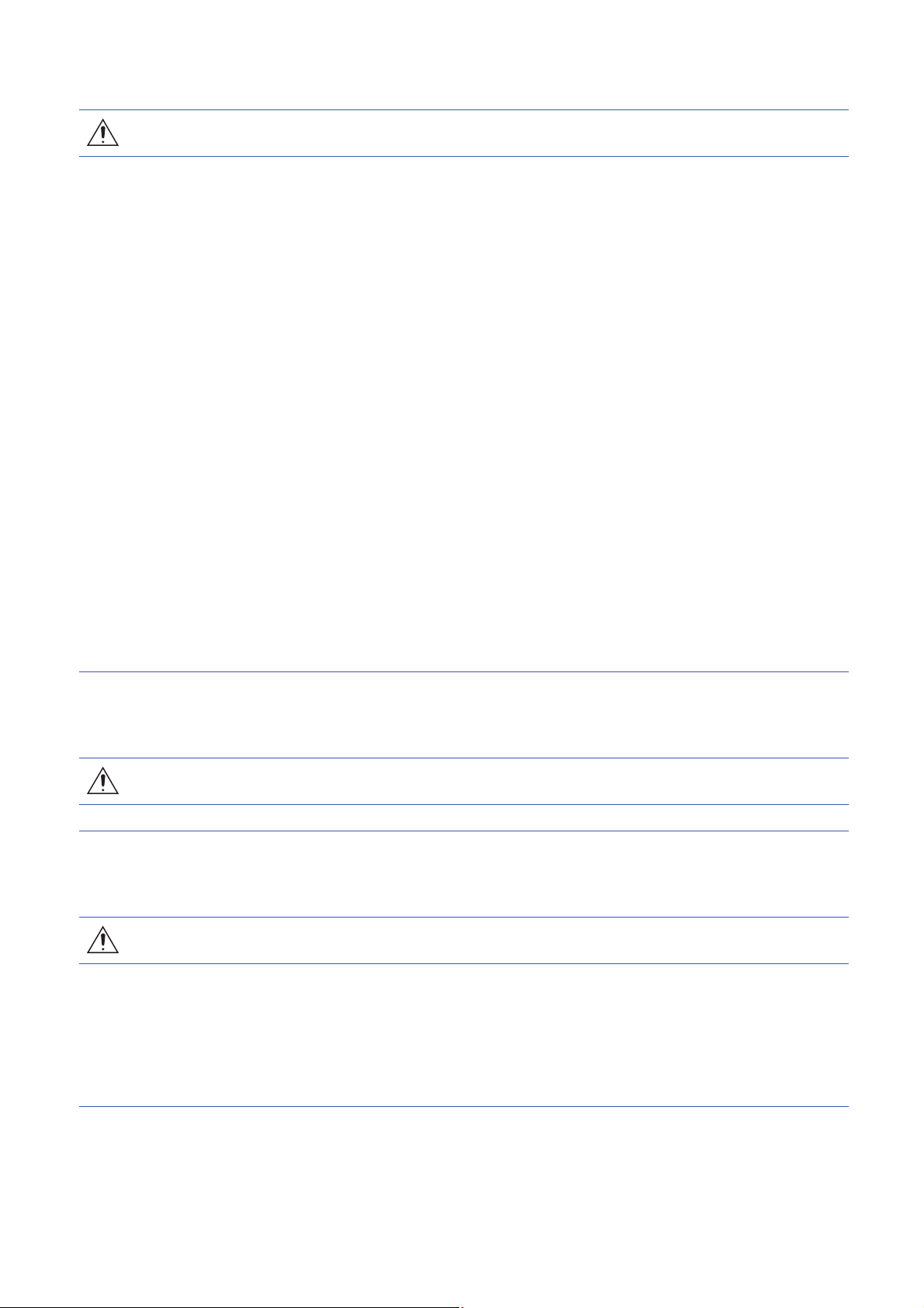
iQ Sensor Solution is a solution to manage both partner products and programmable controllers with an engineering tool.
By sharing design information including system design and programming in the whole control system, the system design
efficiency and the programming efficiency can be improved, and the total cost of design, startup, operation, and maintenance
can be reduced.
14
1 iQ Sensor Solution
Page 17
1.1 Features of iQ Sensor Solution
Display a system configuration diagram detected automatically on
Engineering tool.
Devices supporting iQSS
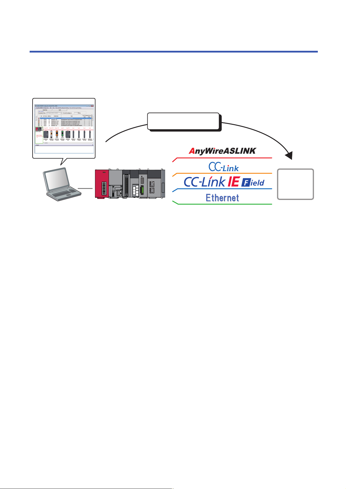
Verify the created system configuration against
the actual system configuration.
Devices supporting iQSS
By performing the functions of an engineering tool supporting iQ Sensor Solution, the information of devices supporting iQSS
connected to various networks can easily be saved/restored.
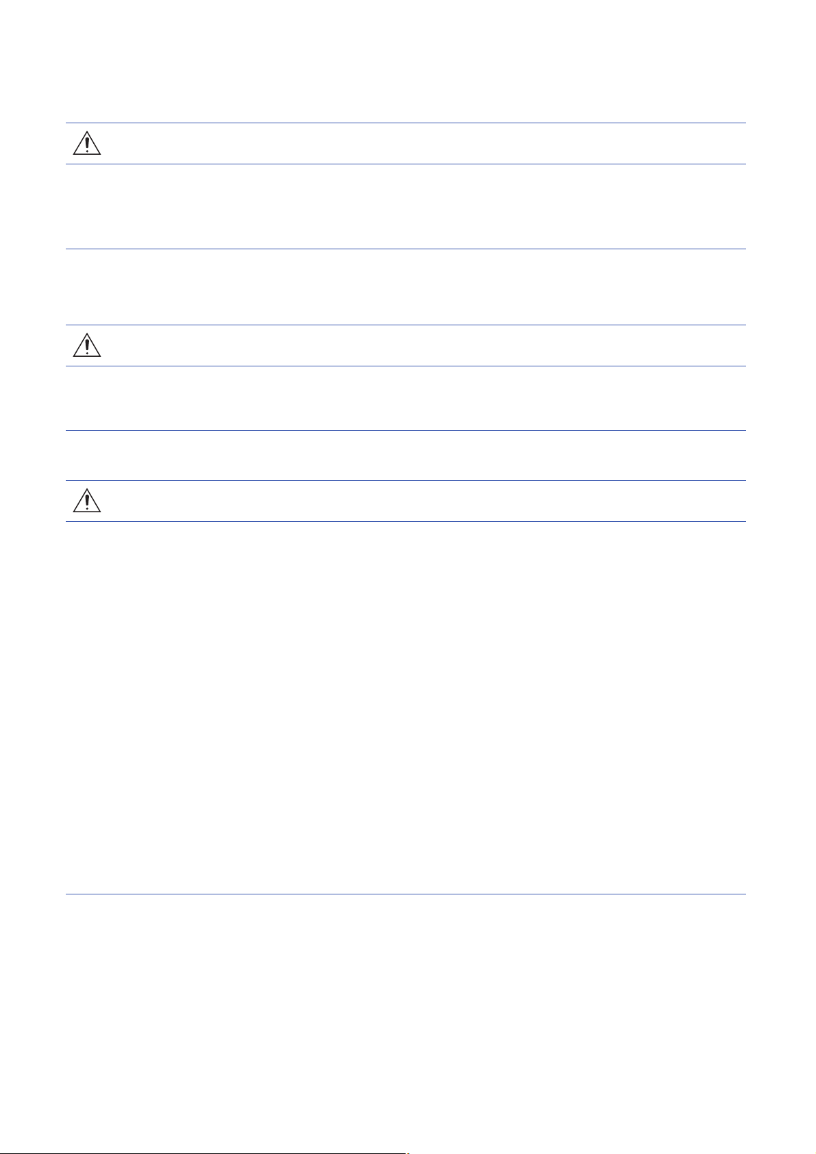
Easy startup
A system configuration diagram can easily be displayed on the screen of an engineering tool by detecting devices supporting
iQSS in the actual system configuration.
In addition, the displayed system configuration can be verified against the actual system configuration, and the
communication setting for Ethernet devices can easily be configured.
Automatic detection of connected devices
A system configuration diagram can automatically be created on the screen of an engineering tool by detecting devices
supporting iQSS in an actual system configuration.
Consequently, man-hours for creating a system configuration diagram at the system startup can be reduced.
1
Verification of connected devices and configurations
A displayed system configuration can be verified against the actual system configuration.
The modification man-hours at the system startup can be reduced.
1 iQ Sensor Solution
1.1 Features of iQ Sensor Solution
15
Page 18

Reflection of the communication setting
Communication settings of devices
supporting iQSS can be configured.
Devices supporting iQSS
Various sensor parameters of devices supporting iQSS can be configured on
the same setting screen.
The communication setting, such as an IP address, for the different type of sensors can be set on the same setting screen.
The setting man-hours can be reduced since the setting can be set to a device supporting iQSS without starting dedicated
tools.
Easy tuning
Sensor parameters can be set efficiently on the same setting screen for sensors of different manufacturers.
Sensor parameter read/write
Sensor parameters can be set by the same operation without starting dedicated tools for each manufacturer.
16
1 iQ Sensor Solution
1.1 Features of iQ Sensor Solution
Page 19
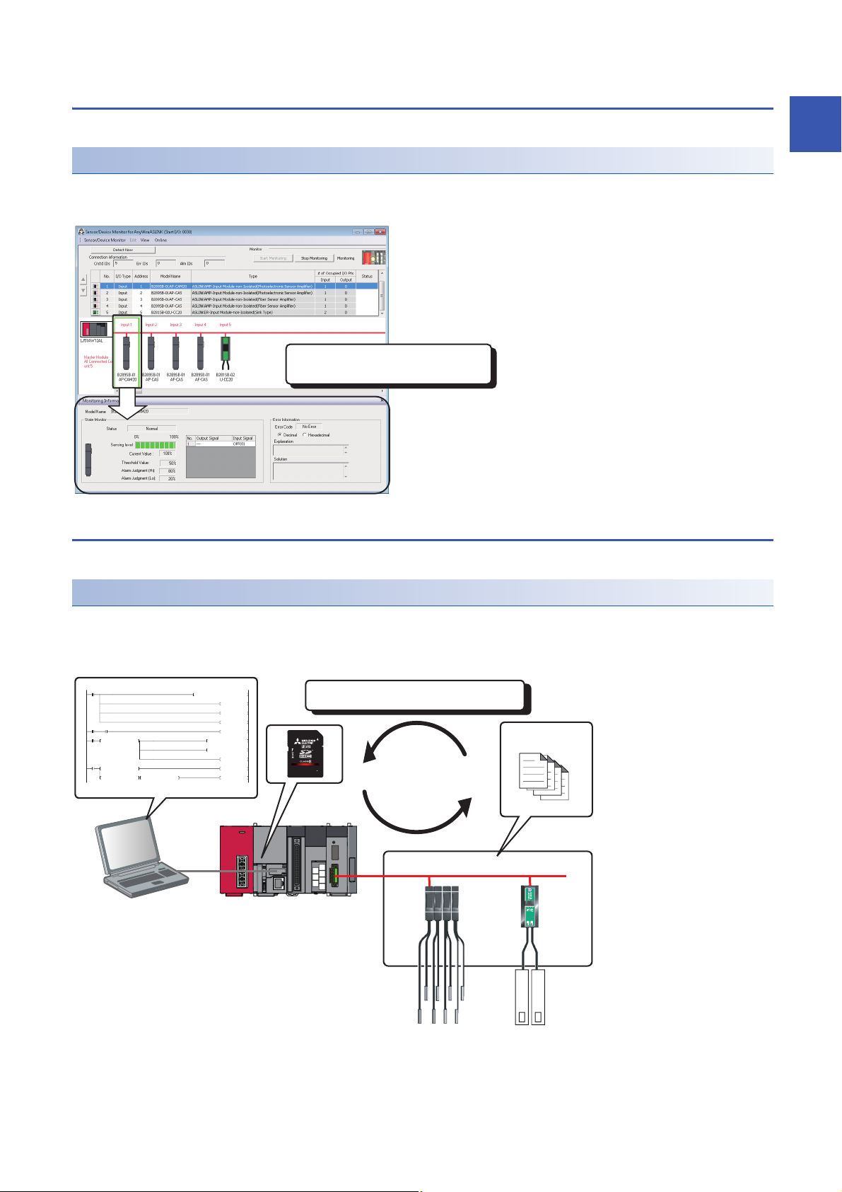
Sensor/device monitor
The status of device supporting iQSS can be
checked.
0
M0
FMOV K0 D5000 K4
RST M3000
RST M3500
SET M1000
72
M1000 SD1288.A
SET M1100
104
M1100
= H0 SD1436 MOV H1050 D1000
MOV D1000 SD1435
SET M1200
173
M1200
= D1000 SD1436 SET M1300
<> D1000 SD1436 <> H0 SD1436 SET M3550
Setting data can be backed up/restored at a time.
Setting data
Devices supporting iQSS
Device supporting iQSS in the actual system configuration can be displayed on a single screen.
Sensor/device monitor
The status of devices supporting iQSS in the actual system configuration can be monitored.
The status and details on devices supporting iQSS can also be checked in the "Monitoring Information" window.
Data backup/restoration
1
The information of devices supporting iQSS can be backed up (saved) to /restored from an SD memory card.
Data backup/restoration
The information of devices supporting iQSS in the actual system configuration can be backed up (saved) to/restored from an
SD memory card.
Man-hours for changing settings can be reduced since data restoration/utilization are simplified.
1 iQ Sensor Solution
1.1 Features of iQ Sensor Solution
17
Page 20
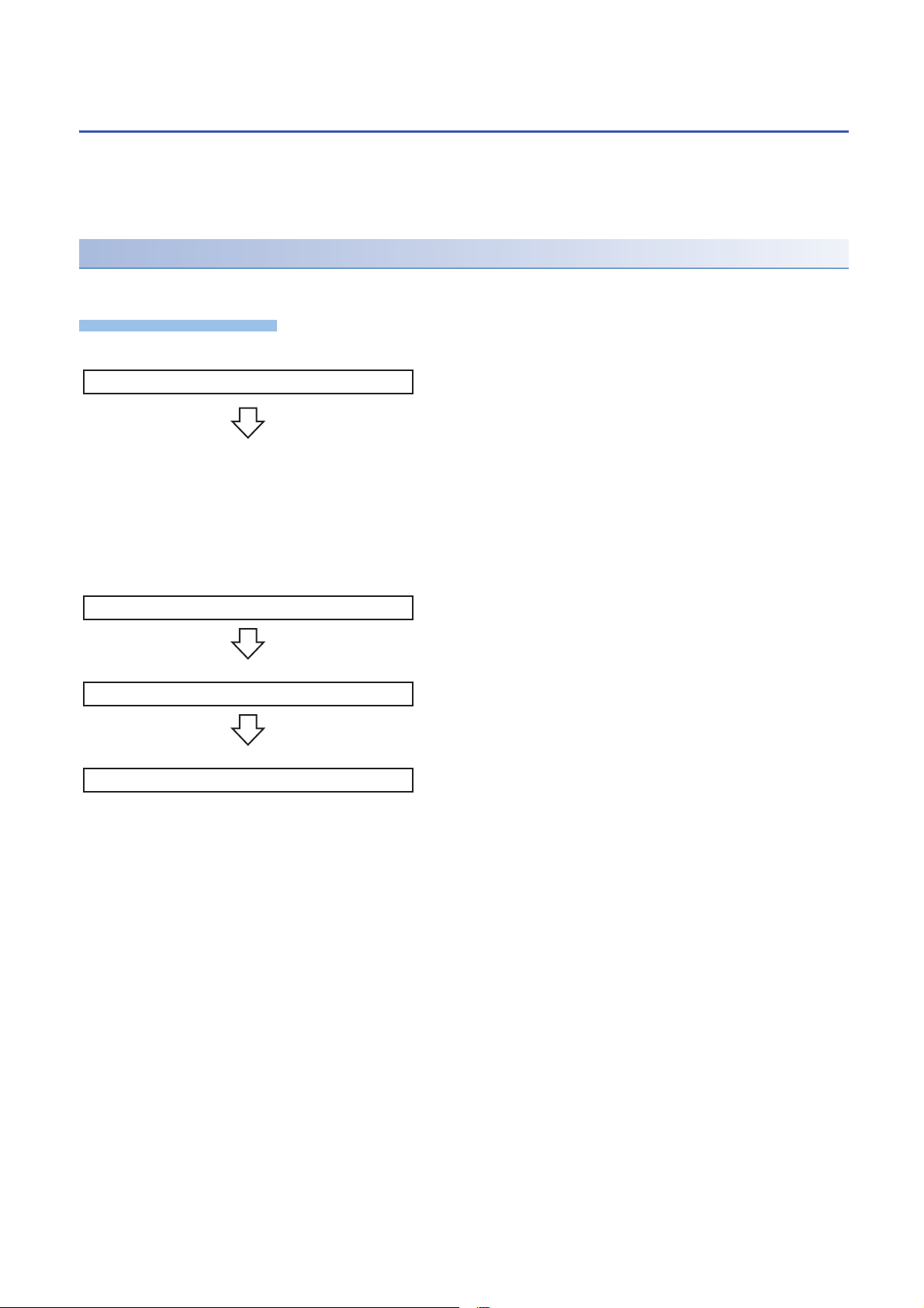
1.2 How to Use iQ Sensor Solution Functions
Operating procedure
1. Easy startup
2. Easy tuning
3. Sensor/device monitor
4. Data backup/restoration
iQ Sensor Solution provides iQ Sensor Solution functions using an engineering tool.
The information of devices supporting iQSS can easily be backed up/restored with the iQ Sensor Solution functions.
For the engineering tools for which these functions can be used, refer to the following section.
Page 337 Engineering Tool and Version List
Procedures from detecting devices to backing up/restoring data
The following shows the procedure to backup/restore the information of devices supporting iQSS in iQ Sensor Solution.
1. Easy startup
• Automatic detection of connected devices
Detect the devices supporting iQSS connected to a network in the
configuration window of an engineering tool.
• Verification of connected devices and configurations
Verify the system configuration displayed in the configuration
window of an engineering tool against the actual system
configuration.
• Reflection of the communication setting
Apply the communication setting set in the configuration window of
an engineering tool to devices supporting iQSS.
2. Easy tuning
• Sensor parameter read/write
Read/Write the parameters of devices supporting iQSS with an
engineering tool.
3. Sensor/device monitor
• Sensor/device monitor
Monitor the connection status of a device supporting iQSS with an
engineering tool.
4. Data backup/restoration
• Data backup/restoration
Backup/restore the information of devices supporting iQSS using
the menu of an engineering tool or a program.
1 iQ Sensor Solution
18
1.2 How to Use iQ Sensor Solution Functions
Page 21

2 iQ Sensor Solution FUNCTIONS
iQ Sensor Solution functions provide easy operations such as the communication setting, programming, data management,
monitoring, and data backup/restoration for devices supporting iQSS with an engineering tool.
2.1 Function List of iQ Sensor Solution
The following functions are available for iQ Sensor Solution.
Purpose iQ Sensor Solution function Description
Easy startup Automatic detection of connected devices To detect devices supporting iQSS, which are connected to a master module or a
built-in Ethernet port CPU, and display the information in a configuration window.
Verification of connected devices and
configurations
Reflection of the communication setting To apply the communication setting to devices supporting iQSS.
Easy tuning Sensor parameter read/write To read and write the sensor parameters of devices supporting iQSS.
Sensor/device monitor Sensor/device monitor To graphically monitor the status of devices supporting iQSS.
Data backup/restoration Data backup/restoration To backup (save) the information of devices supporting iQSS in an SD memory card.
Useful function Linkage with dedicated tools (association
with properties)
Command execution to slave stations To execute commands to a slave station connected to the master/local module.
To verify the actual system configuration against the displayed system configuration.
In addition, this function restores the information of devices supporting iQSS which
was backed up (saved) in an SD memory card.
To start the dedicated tools that is associated with properties and display manuals by
double-clicking the images of devices supporting iQSS on 'Device map area'.
2
Before using iQ Sensor Solution functions
Before using iQ Sensor Solution functions, configure the settings required for communication with devices supporting iQSS in
advance.
iQ Sensor Solution functions cannot be performed unless the communication with devices supporting iQSS is established.
For the system configuration and parameter setting, refer to the manual for the device that supports iQ Sensor Solution to be
used.
Profile registration
iQ Sensor Solution functions cannot be performed unless the profiles of devices supporting iQSS are registered to an
engineering tool.
Register a profile of a device supporting iQSS in advance.
A profile can be registered only by a user logged on to a personal computer with the administrator authority.
For details on the registration methods of a profile, refer to the following manual.
GX Works2 Version 1 Operating Manual (Common)
GX Works3 Operating Manual
MI Configurator Operating Manual
2 iQ Sensor Solution FUNCTIONS
2.1 Function List of iQ Sensor Solution
19
Page 22

2.2 Function List of iQ Sensor Solution for Each
Connection Method
The following tables list the iQ Sensor Solution functions available for each connection method and their references.
GX Works2
In a system configured with MELSEC-L series, Q series, or FX series, the iQ Sensor Solution functions can be performed
using an engineering tool, GX Works2 or MELSOFT Navigator.
AnyWireASLINK
Purpose iQ Sensor Solution function Reference
Easy startup Automatic detection of connected devices Page 27 Detecting Devices Supporting iQSS Automatically
Verification of connected devices and configurations Page 29 Verifying Devices Supporting iQSS Against System
Configuration
Easy tuning Sensor parameter read/write Page 30 Reading/Writing Parameters from/to Devices Supporting iQSS
Sensor/device monitor Sensor/device monitor Page 32 Monitoring Devices Supporting iQSS
Data backup/restoration Data backup/restoration Page 33 Backing up/Restoring Data of Devices Supporting iQSS
Useful function Linkage with dedicated tools (association with
properties)
CC-Link
Page 323 Linkage with dedicated tools (association with properties)
Purpose iQ Sensor Solution function Reference
Easy startup Automatic detection of connected devices Page 56 Detecting Devices Supporting iQSS Automatically
Verification of connected devices and configurations Page 62 Verifying Devices Supporting iQSS Against System
Easy tuning Sensor parameter read/write Page 64 Reading/Writing Parameters from/to Devices Supporting iQSS
Sensor/device monitor Sensor/device monitor Page 66 Monitoring Devices Supporting iQSS
Data backup/restoration Data backup/restoration Page 68 Backing up/Restoring Data of Devices Supporting iQSS
Useful function Linkage with dedicated tools (association with
properties)
Command execution to slave stations Page 324 Command execution to slave station
Configuration
Page 323 Linkage with dedicated tools (association with properties)
CC-Link IE Field Network
Purpose iQ Sensor Solution function Reference
Easy startup Automatic detection of connected devices Page 99 Detecting Devices Supporting iQSS Automatically
Verification of connected devices and
configurations
Easy tuning Sensor parameter read/write Page 105 Reading/Writing Parameters from/to Devices Supporting
Sensor/device monitor Sensor/device monitor Page 107 Monitoring Devices Supporting iQSS
Data backup/restoration Data backup/restoration
Useful function Linkage with dedicated tools (association with
properties)
Command execution to slave stations Page 324 Command execution to slave station
*1 This function can be performed to a device supporting iQSS, which is connected to a bridge module (NZ2AW1GFAL).
*2 The backup/restoration function can be performed with a program.
*1
*2
Page 104 Verifying Devices Supporting iQSS Against System
Configuration
iQSS
Page 108 Backing up/Restoring Data of Devices Supporting iQSS
Page 323 Linkage with dedicated tools (association with properties)
20
2 iQ Sensor Solution FUNCTIONS
2.2 Function List of iQ Sensor Solution for Each Connection Method
Page 23

CC-Link IE Field Network Basic
Purpose iQ Sensor Solution function Reference
Easy startup Automatic detection of connected devices CC-Link IE Field Network Basic Reference Manual
Reflection of the communication setting
Easy tuning Sensor parameter read/write
Useful function Linkage with dedicated tools (association with
properties)
Command execution to slave stations Page 324 Command execution to slave station
Page 323 Linkage with dedicated tools (association with properties)
Ethernet
Purpose iQ Sensor Solution function Reference
Easy startup Automatic detection of connected devices Page 137 Detecting Devices Supporting iQSS Automatically
Reflection of the communication setting Page 139 Applying the Communication Setting to a Device Supporting
Easy tuning Sensor parameter read/write Page 141 Reading/Writing Parameters from/to Devices Supporting
Sensor/device monitor Sensor/device monitor Page 143 Monitoring Devices Supporting iQSS
Data backup/restoration Data backup/restoration Page 144 Backing up/Restoring Data of Devices Supporting iQSS
Useful function Linkage with dedicated tools (association with
properties)
iQSS
iQSS
Page 323 Linkage with dedicated tools (association with properties)
GX Works3
2
In a system configured with MELSEC iQ-R series or MELSEC iQ-F series, the iQ Sensor Solution functions can be performed
using an engineering tool, GX Works3 or MELSOFT Navigator.
AnyWireASLINK
Purpose iQ Sensor Solution function Reference
Easy startup Automatic detection of connected devices Page 167 Detecting Devices Supporting iQSS Automatically
Easy tuning Sensor parameter read/write Page 169 Reading/Writing Parameters from/to Devices Supporting
Sensor/device monitor Sensor/device monitor Page 170 Monitoring Devices Supporting iQSS
Data backup/restoration Data backup/restoration Page 171 Backing up/Restoring Data of Devices Supporting iQSS
Useful function Linkage with dedicated tools (association with
properties)
iQSS
Page 323 Linkage with dedicated tools (association with properties)
CC-Link
Purpose iQ Sensor Solution function Reference
Easy startup Automatic detection of connected devices Page 198 Detecting Devices Supporting iQSS Automatically
Easy tuning Sensor parameter read/write Page 203 Reading/Writing Parameters from/to Devices Supporting
iQSS
Sensor/device monitor Sensor/device monitor Page 205 Monitoring Devices Supporting iQSS
Data backup/restoration Data backup/restoration Page 206 Backing up/Restoring Data of Devices Supporting iQSS
Useful function Command execution to slave stations Page 324 Command execution to slave station
CC-Link IE Field Network
Purpose iQ Sensor Solution function Reference
Easy startup Automatic detection of connected devices Page 245 Detecting Devices Supporting iQSS Automatically
Easy tuning Sensor parameter read/write Page 247 Reading/Writing Parameters from/to Devices Supporting
iQSS
Sensor/device monitor Sensor/device monitor Page 252 Monitoring Devices Supporting iQSS
Data backup/restoration Data backup/restoration Page 253 Backing up/Restoring Data of Devices Supporting iQSS
2 iQ Sensor Solution FUNCTIONS
2.2 Function List of iQ Sensor Solution for Each Connection Method
21
Page 24

Purpose iQ Sensor Solution function Reference
Useful function Linkage with dedicated tools (association with
properties)
Command execution to slave stations Page 324 Command execution to slave station
Page 323 Linkage with dedicated tools (association with properties)
22
2 iQ Sensor Solution FUNCTIONS
2.2 Function List of iQ Sensor Solution for Each Connection Method
Page 25

CC-Link IE Field Network Basic
Purpose iQ Sensor Solution function Reference
Easy startup Automatic detection of connected devices CC-Link IE Field Network Basic Reference Manual
Reflection of the communication setting
Easy tuning Sensor parameter read/write
Useful function Linkage with dedicated tools (association with
properties)
Command execution to slave stations Page 324 Command execution to slave station
Page 323 Linkage with dedicated tools (association with properties)
Ethernet
Purpose iQ Sensor Solution function Reference
Easy startup Automatic detection of connected devices Page 279 Detecting Devices Supporting iQSS Automatically
Reflection of the communication setting Page 282 Applying the Communication Setting to a Device Supporting
Easy tuning Sensor parameter read/write Page 284 Reading/Writing Parameters from/to Devices Supporting
Sensor/device monitor Sensor/device monitor Page 285 Monitoring Devices Supporting iQSS
Data backup/restoration Data backup/restoration Page 286 Backing up/Restoring Data of Devices Supporting iQSS
Useful function Linkage with dedicated tools (association with
properties)
iQSS
iQSS
Page 323 Linkage with dedicated tools (association with properties)
2
2 iQ Sensor Solution FUNCTIONS
2.2 Function List of iQ Sensor Solution for Each Connection Method
23
Page 26

MI Configurator
In a system configured with a MELIPC, the iQ Sensor Solution functions can be performed using an engineering tool, MI
Configurator.
CC-Link IE Field Network
Purpose iQ Sensor Solution function Reference
Easy startup Automatic detection of connected devices Page 311 Detecting Devices Supporting iQSS Automatically
Easy tuning Sensor parameter read/write Page 313 Reading/Writing Parameters from/to Devices Supporting
CC-Link IE Field Network Basic
Purpose iQ Sensor Solution function Reference
Easy startup Automatic detection of connected devices CC-Link IE Field Network Basic Reference Manual
Reflection of the communication setting
Easy tuning Sensor parameter read/write
Ethernet
Purpose iQ Sensor Solution function Reference
Easy startup Automatic detection of connected devices Page 318 Detecting Devices Supporting iQSS Automatically
Reflection of the communication setting Page 320 Applying the Communication Setting to a Device Supporting
Easy tuning Sensor parameter read/write Page 322 Reading/Writing Parameters from/to Devices Supporting
iQSS
iQSS
iQSS
24
2 iQ Sensor Solution FUNCTIONS
2.2 Function List of iQ Sensor Solution for Each Connection Method
Page 27

PART 2 GX Works2
This part explains the operation methods when using the iQ Sensor Solution functions in GX Works2/
MELSOFT Navigator.
3 AnyWireASLINK
4 CC-Link
5 CC-Link IE Field Network
6 Ethernet
PART 2
25
Page 28
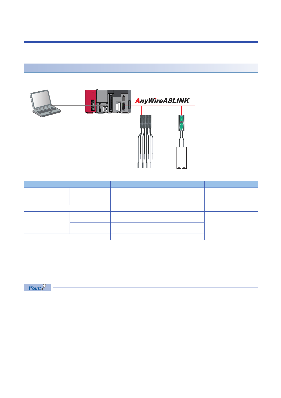
3 AnyWireASLINK
Engineering tool CPU module AnyWireASLINK master module
ASLINKAMP (Input) ASLINKER (Input)
This chapter explains the operation methods when using iQ Sensor Solution functions for MELSEC-L series, Q series, or FX
series via AnyWireASLINK.
System configuration
This section explains the iQ Sensor Solution functions for AnyWireASLINK using the following system configuration.
Type Model name Manufacturer
Engineering tool GX Works2 SWnDND-GXW2 and SWnDNC-GXW2 ('n' indicates its
CPU module LCPU L26CPU-BT
AnyWireASLINK master module LJ51AW12AL
ASLINKAMP (Input) Photoelectric sensor B289SB-01AP-CAM20 (ASLINKAMP master)
Fiber sensor B289SB-01AF-CAS (ASLINKAMP slave)
ASLINKER (Input) B281SB-02U-CC20
For details on the devices supporting iQSS and the iQ Sensor Solution functions available for AnyWireASLINK, refer to the
following section.
Page 325 Devices that Support iQ Sensor Solution
For information on the engineering tools available for iQ Sensor Solution and the versions of engineering tools supporting
each iQ Sensor Solution function, refer to the following section.
Page 337 Engineering Tool and Version List
• Before using each iQ Sensor Solution function, complete the installation and wiring of the actual system
configuration, and set PLC parameters and other settings required for communication with a device
supporting iQSS such as the address setting and the amplifier teaching.
• Make sure to set the address occupied by a slave module so as not to exceed the number of operating
points set in a master module.
For details on the settings, refer to the following manual.
MELSEC-Q/L AnyWireASLINK Master Module User's Manual
version.)
B289SB-01AP-CAS (ASLINKAMP slave)
B289SB-01AF-CAS (ASLINKAMP slave)
Mitsubishi Electric Corporation
AnyWire Corporation
26
3 AnyWireASLINK
Page 29
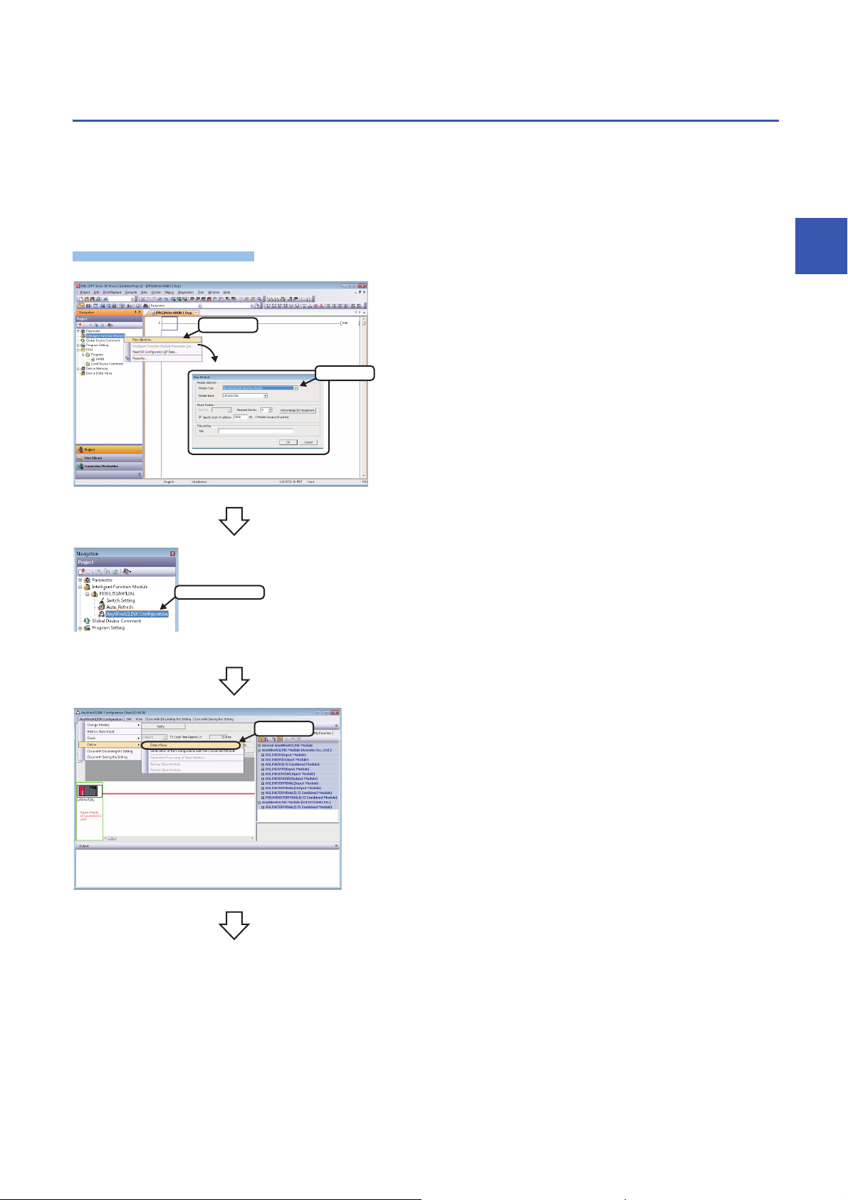
3.1 Detecting Devices Supporting iQSS Automatically
Operating procedure
1. Select
2. Select
Double-click
Select
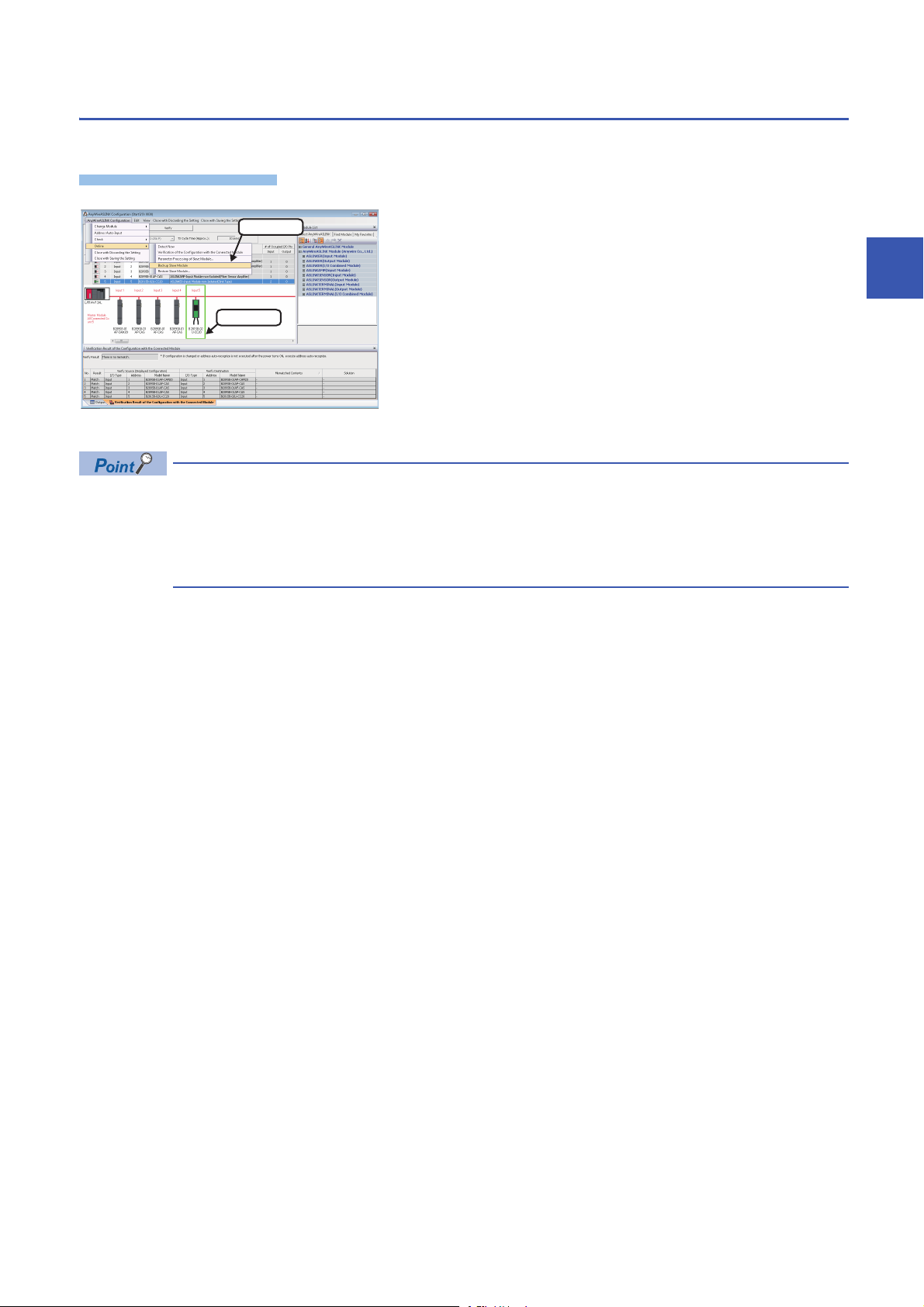
A slave module connected to an AnyWireASLINK master module can be detected and the information can be displayed in the
"AnyWireASLINK Configuration" window.
For the creation method of a new project and the operation methods of the "AnyWireASLINK Configuration" window, refer to
the following manual.
GX Works2 Version 1 Operating Manual (Intelligent Function Module)
1. Create a new project in an engineering tool.
2. Add the data of AnyWireASLINK master module to "Intelligent
Function Module" on the Project view.
3
3. Double-click "AnyWireASLINK Configuration" on the Project
view.
4. Select [AnyWireASLINK Configuration] [Online] [Detect
Now] in the "AnyWireASLINK Configuration" window.
3 AnyWireASLINK
3.1 Detecting Devices Supporting iQSS Automatically
27
Page 30
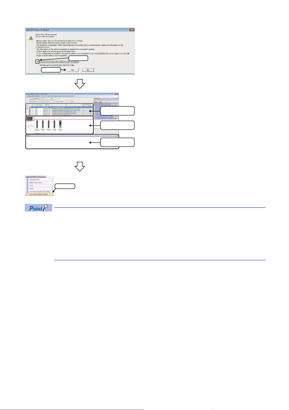
5. When an automatic address detection is required, select the
1. Check
2. Click
List of modules
Device map area
Output window
Select
"Execute Detect Now after Address Auto-recognition"
checkbox, then click the [Yes] button.
For a case in which an automatic address detection is required,
refer to the following manual.
MELSEC-Q/L AnyWireASLINK Master Module User's Manual
The actual system configuration is displayed in the
"AnyWireASLINK Configuration" window.
6. Select [AnyWireASLINK Configuration] [Close with Saving
the Setting] in the "AnyWireASLINK Configuration" window.
The setting in the "AnyWireASLINK Configuration" window is
saved and completed.
• The system configuration cannot be detected if an error occurs on the AnyWireASLINK master module.
Take corrective actions and perform an automatic detection of connected devices again.
• Error information is displayed in the "Output" window when an error occurred.
Double-click it and correct the error at the jumped destination.
• When a module which is not a device supporting iQSS is detected, it is displayed as shown below:
"Module with No Profile Found"
"General Module"
■Detection methods of a system configuration
The system configuration of AnyWireASLINK can also be detected by either of the following operations.
• Click the [Detect Now] button in the "AnyWireASLINK Configuration" window.
• Select [Online] [Detect Now] in MELSOFT Navigator. (FXCPUs do not support this function.)
For the operation methods of MELSOFT Navigator, refer to the following manual.
(Let's start iQ Works Version 2)
28
3 AnyWireASLINK
3.1 Detecting Devices Supporting iQSS Automatically
Page 31

3.2 Verifying Devices Supporting iQSS Against
Operating procedure
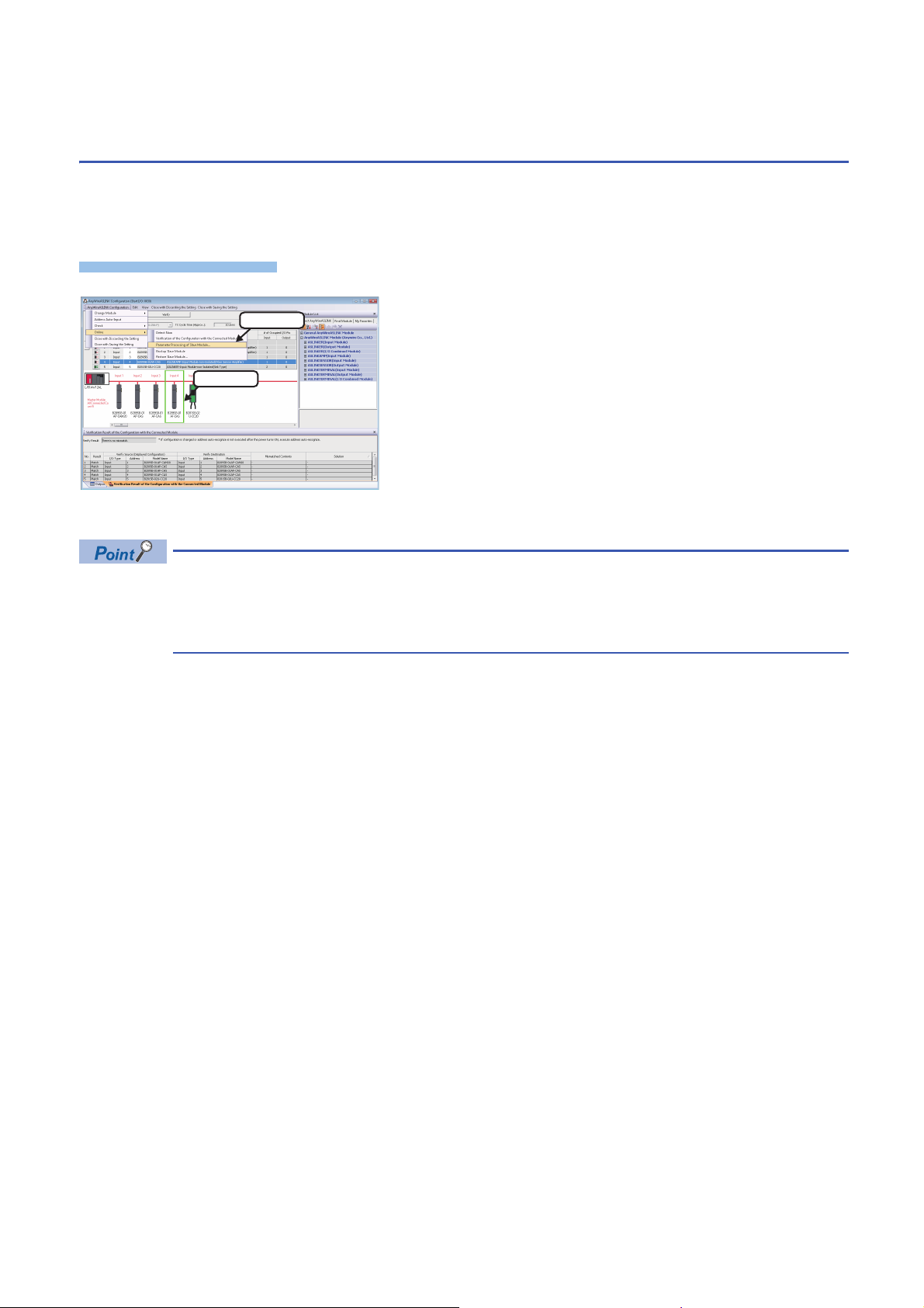
1. Select
2. Check
3. Click
System Configuration
The system configuration displayed in the "AnyWireASLINK Configuration" window can be verified against the slave modules
connected to an AnyWireASLINK master module.
The result is displayed in the "Verification Result of the Configuration with the Connected Module" window.
Verify a system configuration when it is manually created or edited.
1. Select [AnyWireASLINK Configuration] [Online]
[Verification of the Configuration with the Connected Module]
in the "AnyWireASLINK Configuration" window.
2. When an automatic address detection is required, select the
"Execute Verification of the Configuration with the Connected
Module after Address Auto-recognition" checkbox, then click
the [Yes] button.
For a case in which an automatic address detection is required,
refer to the following manual.
MELSEC-Q/L AnyWireASLINK Master Module User's Manual
3
The verification results are displayed in the "Verification Result of
the Configuration with the Connected Module" window.
The display is switched by right-clicking on the "Verification Result of the Configuration with the Connected
Module" window and selecting "Display All"/"Display Mismatch Only"/"Display other than Match".
■Verification methods of system configuration information
The system configuration information of AnyWireASLINK can also be verified by either of the following operations.
• Click the [Verify] button in the "AnyWireASLINK Configuration" window.
• Select [Online] [Verification of the Configuration with the Connected Module] in MELSOFT Navigator. (FXCPU does not
support this function.)
For the operation methods of MELSOFT Navigator, refer to the following manual.
(Let's start iQ Works Version 2)
3 AnyWireASLINK
3.2 Verifying Devices Supporting iQSS Against System Configuration
29
Page 32
3.3 Reading/Writing Parameters from/to Devices
Window
2. Select
1. Select
Supporting iQSS
Parameters can be read from and written to a slave module.
For the operation methods of the "AnyWireASLINK Configuration" window, refer to the following manual.
GX Works2 Version 1 Operating Manual (Intelligent Function Module)
1. Select a target device supporting iQSS in 'List of modules' or
'Device map area' in the "AnyWireASLINK Configuration"
window, and select [AnyWireASLINK Configuration]
[Online] [Parameter Processing of Slave Module].
2. Read/write the parameters on the "Parameter Processing of
Slave Module" screen.
• The data backup/restoration function is useful to read/write the parameters of multiple devices supporting
iQSS in a batch. (Page 33 Backing up/Restoring Data of Devices Supporting iQSS)
• The useful function (linkage with dedicated tools) can also be used in the "AnyWireASLINK Configuration"
window. (Page 323 Linkage with dedicated tools (association with properties))
■Display methods of the "Parameter Processing of Slave Module" screen
The "Parameter Processing of Slave Module" screen can also be displayed by any of the following operations.
• Select a target module in 'List of modules' or 'Device map area' in the "AnyWireASLINK Configuration" window, then rightclick and select [Online] [Parameter Processing of Slave Module] from the shortcut menu.
• Select a target module in the 'List of modules' or 'Device map area' on the "Sensor/Device Monitor for AnyWireASLINK"
screen, and select [Online] [Parameter Processing of Slave Module].
• Select a target module in the 'List of modules' or 'Device map area' on the "Sensor/Device Monitor for AnyWireASLINK"
screen, then right-click and select [Parameter Processing of Slave Module] from the shortcut menu.
For details on the "Sensor/Device Monitor for AnyWireASLINK" screen, refer to the following section.
Page 32 Monitoring Devices Supporting iQSS
30
3 AnyWireASLINK
3.3 Reading/Writing Parameters from/to Devices Supporting iQSS
Page 33
Operating procedure
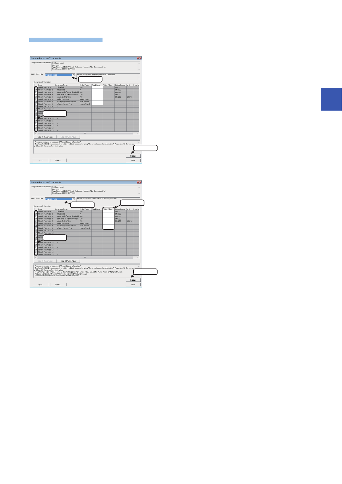
■Reading parameters
1. Select
2. Check
3. Click
3. Enter
1. Select
2. Check
4. Click
■Writing parameters
1. Select "Parameter read".
2. Select a parameter to be read.
3. Click the [Execute] button.
The selected parameter is read and the value is displayed in the
column of "Read Value".
3
1. Select "Parameter write".
2. Select a parameter to be written.
3. Enter a value in the column of "Write Value".
4. Click the [Execute] button.
The value entered in the column of "Write Value" is written to the
device supporting iQSS.
3 AnyWireASLINK
3.3 Reading/Writing Parameters from/to Devices Supporting iQSS
31
Page 34
3.4 Monitoring Devices Supporting iQSS
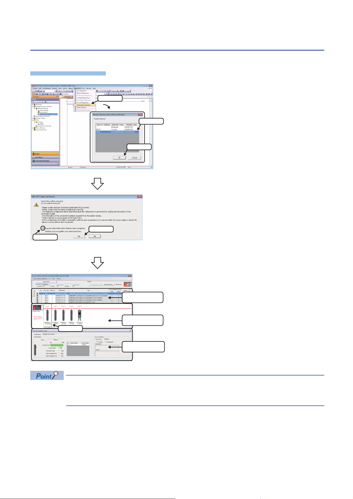
Operating procedure
1. Select
2. Select
3. Click
1. Check
2. Click
List of modules
Select
Device map area
Monitoring Information
window
The connection statuses of devices supporting iQSS can be monitored.
1. Select [Diagnostics] [Sensor/Device Monitor] with an
engineering tool.
2. Select an AnyWireASLINK master module in the "Module
Selection (Sensor/Device Monitor)" screen, and click the [OK]
button.
3. When an automatic address detection is required, select the
"Execute Detect Now after Address Auto-recognition"
checkbox, then click the [Yes] button.
For a case in which an automatic address detection is required,
refer to the following manual.
MELSEC-Q/L AnyWireASLINK Master Module User's Manual
The "Sensor/Device Monitor for AnyWireASLINK" screen appears.
4. Select a target device supporting iQSS to be monitored in
'List of modules' or 'Device map area' in the "Sensor/Device
Monitor for AnyWireASLINK" screen.
The status of the selected device supporting iQSS is displayed in
the "Monitoring Information" window. (Page 343
AnyWireASLINK)
Sensor/device monitor reads a large volume of information from a CPU module at once.
Therefore, the processing speed of the sensor/device monitor function may decrease depending on the set
communication route.
32
3 AnyWireASLINK
3.4 Monitoring Devices Supporting iQSS
Page 35
3.5 Backing up/Restoring Data of Devices Supporting
0003_IN_ _0517
0003_IN_ _0513
iQSS
ASLINK
20141210_12
0
M0
FMOV K0 D5000 K4
RST M3000
RST M3500
SET M1000
72
M1000 SD1288.A
SET M1100
104
M1100
= H0 SD1436 MOV H1050 D1000
MOV D1000 SD1435
SET M1200
173
M1200
= D1000 SD1436 SET M1300
<> D1000 SD1436 <> H0 SD1436 SET M3550
234
M1300
MOV H103 SD1437
MOV H0FFFF SD1438
MOV H3FF SD1439
MOV H1 SD1444
SET SM1436
Data backup/restoration
command
Address 1 to 4
ID513 (201H)to
ID516 (204H)
Address 5
ID517 (205H)
SD memory card
Data backup
Address 1
ID513 (201H)
Address 1
Setting data of
ID513 (201H)
Setting data
Data restoration
Address 5
ID517 (205H)
Data backup
Address 5
Setting data of
ID517 (205H)
Setting data
Data restoration
iQSS
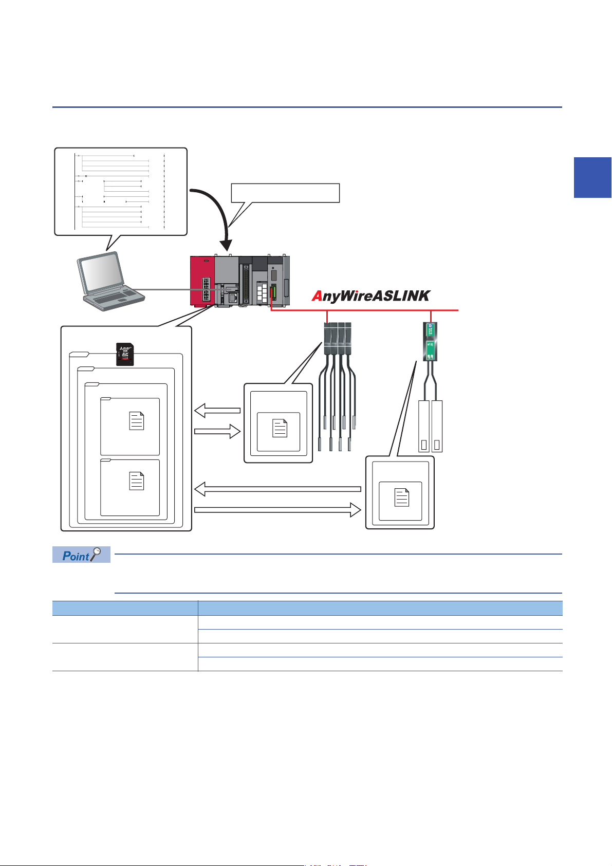
Backing up the information of a device supporting iQSS to an SD memory card and restoring it to a module simplifies the
setting change for changeover.
3
Function Reference
Data backup Page 37 Data backup
Data restoration Page 45 Data restoration
In such a case as limited production of diversified products, the data backup/restoration function is useful for
switching multiple sensor settings from for product A to for product B in a batch.
Page 38 Program execution for data backup
Page 46 Program execution for data restoration
3.5 Backing up/Restoring Data of Devices Supporting iQSS
3 AnyWireASLINK
33
Page 36
Backup folder/file
/
iQSS ASLINK
20141210_12
0003_ IN_ _0513
0003_ IN_ _0514
1) Backup folder
(Date_Number)
Maximum of 100
2) Backup folder
(Start I/O number_I/O
Type_ID Number)
Backup data
Root directory
ID_IN__0513.QBR
(Backup file)
SSBRINF.QBI
(System file)
Backup data
ID_IN__0514.QBR
(Backup file)
SSBRINF.QBI
(System file)
2014 12 10 12
Arbitrary number (2-digit (00 to 99) decimal)
Backup date (2-digit decimal)
Backup month (2-digit decimal)
Backup year (4-digit decimal)
0003 IN 0513
ID number (4-digit decimal)
OUT or IN_ (OUT: output slave module IN_: input/combined slave module)
AnyWireASLINK master module start I/O number (4-digit hexadecimal) (A value of start I/O number divided by 16)
ID
IN_ 0513
.QBR
ID number (4-digit decimal)
OUT or IN_ (OUT: output slave module IN_: input/combined slave module)
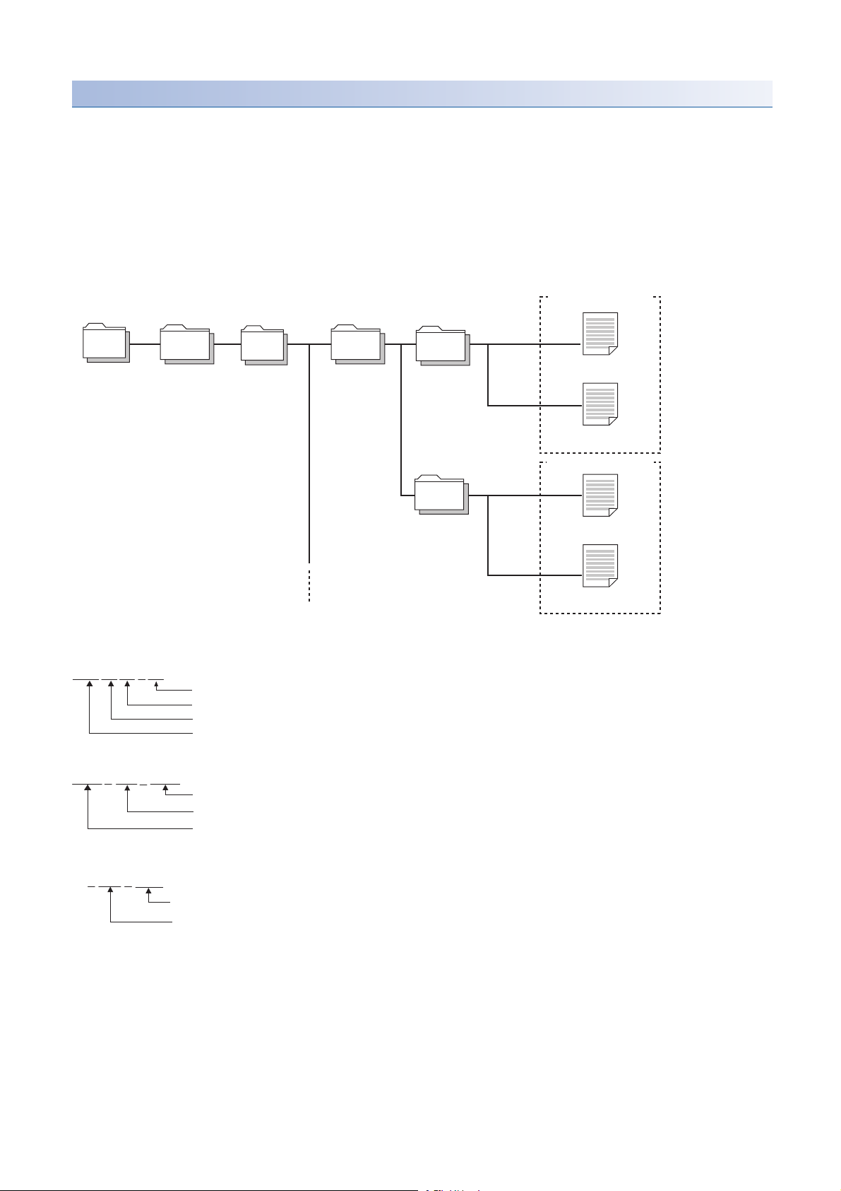
Backup data is created in the 'iQSS' folder in the root directory when backing up the data.
If no 'iQSS' folder exists when backing up the data, an 'iQSS' folder will be newly created.
Up to 100 backup folders (date_number) can be created in the 'ASLINK' folder.
Do not change a backup folder name, configuration or saved file. Otherwise, data may not be restored properly.
For the backup file capacity, refer to the following section.
Page 368 Backup File Capacity
■Backup folder configuration
The following figure shows the backup folder configuration in an SD memory card.
■Backup folder name
1) Date_Number
2) Start I/O number_I/O type_ID number
■Backup file name
34
3 AnyWireASLINK
3.5 Backing up/Restoring Data of Devices Supporting iQSS
Page 37

Points to be checked before data backup/restoration
■Check the availability of data backup/restoration
The data can be backed up and restored when an AnyWireASLINK master module satisfies the following conditions.
Perform the automatic address detection function and the parameter batch read function before data backup/restoration.
Condition to be checked Master module X/Y signal Signal status
Module READY Xn0 ON
DP/DN short error Xn1 OFF
Transmission cable voltage drop error Xn3 OFF
DP/DN disconnection error Xn4 OFF
Slave module alarm signal X(n+1)0 OFF
Parameter access completion flag X(n+1)1 ON
Parameter access error X(n+1)2 OFF
Automatic address detection flag X(n+1)4 OFF
*1 Excluding when the error code is 0131H.
*1
Considerations for data backup/restoration
■Use of an SD memory card
• During a data backup or restoration, do not perform the following actions: turning OFF the power, resetting a module, and
inserting or removing an SD memory card.
Otherwise, the data backup or restoration will be interrupted and the data will not be backed up or restored properly.
• Normal backup data cannot be created if the memory size or the number of files exceeds the maximum storage capacity of
an SD memory card during a data backup.
3
■Operations with a display unit during data backup
If any of the following operations are performed with a display unit during data backup, the operation will be completed
abnormally and the error is displayed on the display unit.
Operation name
Project data batch save/load function
File deletion on the "Memory card operation menu" screen of a display unit
3 AnyWireASLINK
3.5 Backing up/Restoring Data of Devices Supporting iQSS
35
Page 38

■Unavailable operations and functions at the same time as data backup
20141210_12
Do not change.
If any of the following operations and functions are performed during data backup, the backup will be completed abnormally
and the error cause is stored in SD1452 (iQ Sensor Solution backup/restoration error cause in a module).
The error is returned to the request source which performs the operation or function.
Operation/function name
Operation with an engineering tool Change TC setting
Operations with CPU Module Logging Configuration Tool Data logging function
Others Writing or deleting files using FTP or MC protocol
*1
Online change (ladder mode)
Online change (inactive block) for SFC program
Write to PLC (including writing data to the CPU module during RUN)
Write title
Password/keyword
• New (registration/change)
• Delete
• Disable
Format PLC memory
Clear PLC memory (Clear all file registers)
Arrange PLC memory
Delete PLC data
Write/delete PLC user data
Program memory batch download
CPU module change function with SD memory card
Sampling trace function
• Start trace
• Register trace
• Write to PLC
Writing protocol setting data to the CPU module (predefined protocol support function)
Project data batch save/load function
• Deleting/writing the data logging setting
• Stopping data logging operation
• Deleting data logging file(s)
File transfer function (FTP server) of the built-in Ethernet function
File transfer function (FTP client) of the built-in Ethernet function
Register/cancel display unit menu
CPU module data backup/restoration function
36
*1 Available operations and functions differ between LCPUs and QCPUs. For details, refer to the user's manual of a CPU module used.
When data is backed up or restored during a data logging, the performance of the data logging will be reduced.
Therefore, sampled data may be partially missed and the data missing frequency may be increased.
■Communication load
When data is backed up or restored, the load of the service processing is temporarily increased. Consequently, a timeout
error may occur in other communications.
To avoid a timeout error, review the value set for "Service Processing Setting" on the [PLC System] tab in "PLC parameter".
■Backup folder name
Do not change an underscore and a subsequent number of a backup folder name (date_number).
If they are changed, the data may not be restored properly.
3 AnyWireASLINK
3.5 Backing up/Restoring Data of Devices Supporting iQSS
Page 39
Data backup
Operating procedure
2. Select
1. Select
Information of a device supporting iQSS can be saved in an SD memory card for each ID by using an engineering tool.
1. Select a target device supporting iQSS in 'List of modules' or
'Device map area' in the "AnyWireASLINK Configuration"
window, and select [AnyWireASLINK Configuration]
[Online] [Backup Slave Module].
2. Read the message, and click the [Yes] or [OK] button.
Data is backed up.
The initial values of the backup setting (SD1438 and SD1444) are as follows:
• SD1438 (Folder number setting): FFFFH (automatic specification)
• Lower 8 bits of SD1444 (operation setting on error): 0H (continue)
Use a program when backing up data with the settings other than the one above. (Page 38 Program
execution for data backup)
3
■Other methods of data backup
Data can be backed up by the following methods.
• Select a target module in the 'List of modules' or 'Device map area' in the "AnyWireASLINK Configuration" window, then
right-click and select [Backup Slave Module] from the shortcut menu.
• Select a target module in the 'List of modules' or 'Device map area' on the "Sensor/Device Monitor for AnyWireASLINK"
screen, then right-click and select [Backup Slave Module] from the shortcut menu.
3 AnyWireASLINK
3.5 Backing up/Restoring Data of Devices Supporting iQSS
37
Page 40
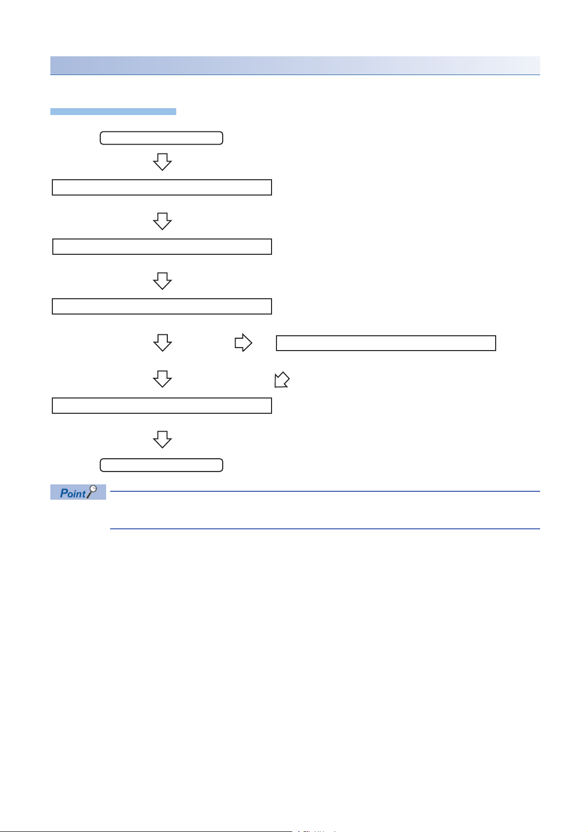
Program execution for data backup
Operating procedure
Start
Acquiretherighttousespecialrelays/registers.
Completionofright-to-useacquisition
Setthesettingsfordatabackup.
Requestadatabackup.
Executionofdatabackup
Requestacancellationofbackupprocess.
Backuperror
Normalcompletionofbackupprocess
Cancellationofbackupprocess
Enablethenextbackupprocess.
Complete
Information of a device supporting iQSS can be backed up in an SD memory card with a program.
Page 39 Acquiring a right to use
Page 39 Setting the backup setting
Page 40 Performing a data backup
Page 40 Releasing the right to use
For details on special relays (SM) and special registers (SD), refer to the following section.
Page 355 Special Relay (SM)/Special Register (SD) List
Page 40 Requiring a data backup cancellation
38
3 AnyWireASLINK
3.5 Backing up/Restoring Data of Devices Supporting iQSS
Page 41

Execution method of data backup
The target device for data backup can be set with a program.
■Acquiring a right to use
Set a value within the range from 1000H to 1FFFH to SD1435.
Right to use for data backup
• Special relays (SM) and special registers (SD) are used for data backup.
• To prevent the same special relay (SM) and special register (SD) from being set at the same time, acquiring
a right to use of them for data backup is required.
• To acquire a right to use, specify a value which is not duplicate with values for other request sources to
SD1435, and check that the value set to SD1435 is stored to SD1436.
• Normal operation cannot be assured if the data backup function is performed without confirming the
acquisition of a right to use.
■Setting the backup setting
1. Setting a target module type
Set the target module type for data backup to the lower 8 bits of SD1437.
Target module type Description
1H: AnyWireASLINK Set the target module type.
2. Setting an execution unit
Set the unit of execution for data backup to the upper 8 bits of SD1437.
Execution unit Description
1H: Module unit Set this to specify all devices supporting iQSS which are connected to the AnyWireASLINK interface module with the
specified start I/O number.
2H: ID unit Set this to specify only the device supporting iQSS with the specified ID number among the devices supporting iQSS
which are connected to the AnyWireASLINK interface module with the specified start I/O number.
3
3. Setting a number for a data backup folder name
Set the number for a backup folder name to SD1438.
Target folder Description
FFFFH: Automatic specification
(Default)
FFFEH: Automatic specification
(folder deletion supported)
00 to 99: Target folder specification Set the number for a backup folder name.
Use the smallest number for a new backup folder name among the unused numbers as the backup folder name.
An error occurs when unused number is no longer available due to such cases as the number of folders reached the
upper limit.
Use the smallest number for a new backup folder name among the unused numbers as the backup folder name.
The oldest folder is deleted and the number of the deleted folder is used for a new backup folder name when unused
number is no longer available due to such cases as the number of folders reached the upper limit.
When another folder with the same number exists, the operation will be as follows:
■For module unit
• The backup folder with the same number is deleted, and a new backup folder is created.
■For ID unit
• Data in the backup folder with the same number is overwritten.
3 AnyWireASLINK
3.5 Backing up/Restoring Data of Devices Supporting iQSS
39
Page 42

4. Setting a target device
• Setting a module
When '1H' (module unit) is set for the execution unit in the step of 'Setting the execution unit', set the start I/O number of a
target device for data backup to SD1439.
Target device (Module) Description
0 to FFH: Start I/O number When '1H' (module unit) is set for the execution unit, set the value obtained by dividing the start I/O number of an
AnyWireASLINK master module, which is connected to a target device supporting iQSS, by 16.
• Setting an ID number
When '2H' (ID unit) is set for the execution unit in the step of 'Setting the execution unit', set the ID number of a target device
for data backup to SD1440.
Target device (ID number) Description
0 to 255 (0FFH): Output slave
module ID number
512 (200H) to 767 (2FFH): Input/
combined slave module ID number
*1 Specify the address + 512 (200H) for an input/combined slave module.
When '2H' (ID unit) is set for the execution unit, set the ID number of a target device supporting iQSS.
*1
5. Setting the operation setting when a data backup error occurs
Set the operation on error to the lower 8 bits of SD1444 in order to backup data for multiple devices supporting iQSS.
Operation on error Description
0H: Continue Set this to continue a data backup even if it fails on some devices while being performed to multiple devices supporting
iQSS.
1H: Stop Set this to stop a data backup even if it fails on some devices while being performed to multiple devices supporting
iQSS.
■Performing a data backup
Data is backed up if SM1436 is turned ON while SD1446 is '1H' (ready).
Once data is backed up, SD1446 will be '2H' (being executed).
■Requiring a data backup cancellation
The data backup stops if SM1442 is turned ON while SD1446 is '1H' (ready) or '2H' (being executed).
■Releasing the right to use
When SM1435 is turned ON after a data backup is completed (including a cancellation or an error), the right to use is released
and the next data backup is ready to be performed.
SM1435 turns ON to OFF when the right to use is released.
If the right to use is released even though it has already been done, SM1435 remains ON since no processing is performed.
In that case, set SM1435 to OFF.
40
3 AnyWireASLINK
3.5 Backing up/Restoring Data of Devices Supporting iQSS
Page 43

Example of a data backup
AnyWireASLINK master module start I/O number 30
Address 1 to 4
ID513 (201H) to
ID516 (204H)
Address 5
ID517 (205H)
Backup target
■Example of a system configuration
The following shows the example of a system configuration for data backup.
• Target module type: AnyWireASLINK
• Execution unit: Module
• Folder number setting: 12
• Target device (target module): Start I/O No.30
• Operation setting on error: Stop
3
3 AnyWireASLINK
3.5 Backing up/Restoring Data of Devices Supporting iQSS
41
Page 44

■Devices used in the program
Device Description Value
M0 Initialization trigger
M1000 Backup execution trigger
M1100 Backup right-to-use request trigger
M1200 Backup right-to-use confirmation trigger
M1300 Backup setting/start trigger
M2000 Backup execution cancellation trigger
M3000 Backup execution normal completion display
M3500 Backup execution abnormal completion display
M3550 Backup right-to-use acquisition failure
D1000 Right-to-use number storage area
D5000 Backup number of normally completed devices
D5001 Backup number of devices completed with an error
D5002 Backup error cause in a module
D5003 Backup error cause in a device
SM1435 Backup execution enabled
SM1436 Backup request
SM1442 Backup cancellation request
SD1435 Backup use request 1010H
SD1436 Backup right-to-use acquisition status
SD1437 Backup target module/execution unit setting Lower 8 bits: 1H
SD1438 Backup folder number setting 12
SD1439 Backup target setting (target module) 3H
SD1444 Operation setting when a data backup error occurs 1H
SD1446 Backup execution status
SD1448 Backup number of normally completed devices
SD1449 Backup number of devices completed with an error
SD1452 Backup error cause in a module
SD1453 Backup error cause in a device
X30 Module READY
X31 DP/DN short error
X33 Transmission cable voltage drop error
X34 DP/DN disconnection error
X40 Slave module alarm signal
X41 Parameter access completion flag
X42 Parameter access error
X44 Automatic address detection flag
Upper 8 bits: 1H
42
For details on special relays (SM) and special registers (SD) to be used and their setting ranges, refer to the
following section.
Page 355 Special Relay (SM)/Special Register (SD) List
3 AnyWireASLINK
3.5 Backing up/Restoring Data of Devices Supporting iQSS
Page 45

0
M0
FMOV K0 D5000 K4
RST M3000
RST M3500
SET M1000
8
M1000
X30 X31 X33 X34 X40 X41 X42 X44
SET M1100
18
M1100
= H0 SD1436 MOV H1010 D1000
MOV D1000 SD1435
SET M1200
27
M1200
= D1000 SD1436 SET M1300
<> D1000 SD1436 <> H0 SD1436 SET M3550
41
M1300
MOV H101 SD1437
MOV K12 SD1438
MOV H3 SD1439
MOV H1 SD1444
SET SM1436
51 = H3 SD1446 SET M3000
MOV SD1448 D5000
57 = H0FF SD1446 SET M3500
MOV SD1449 D5001
MOV SD1452 D5002
MOV SD1453 D5003
67
M3000
SET SM1435
M3500
RST M0
RST M1000
RST M1100
RST M1200
RST M1300
75
M2000
= H1 SD1446 SET SM1442
= H2 SD1446
84 END
■Sample program
3
3.5 Backing up/Restoring Data of Devices Supporting iQSS
3 AnyWireASLINK
43
Page 46

[Initialization]
(0) Initialize the execution result.
Initialize the normal completion display.
Initialize the abnormal completion display.
Set the backup execution trigger.
[Executing data backup]
(8) Set the backup right-to-use request trigger.
[Requesting backup right to use]
(18) Store the right-to-use number.
Set the backup right-to-use request trigger.
Set the backup right-to-use confirmation trigger.
[Checking backup right to use]
(27) Set the backup setting/start trigger.
Display the right-to-use acquisition failure.
[Setting/Starting data backup]
(41) Set the target module/execution unit.
Set the target folder number.
Set the target module.
Set the operation setting when a data backup error occurs.
Set the backup request.
[Checking data backup execution]
(51) Display the normal completion.
Save the number of normally completed devices.
(57) Display the abnormal completion.
Save the number of devices completed with an error.
Save the error code (module error).
Save the error code (device error).
[Enabling the next data backup process]
(67) Enable the data backup execution.
Clear the initialization trigger.
Clear the backup execution trigger.
Clear the backup right-to-use request trigger.
Clear the backup right-to-use confirmation trigger.
Clear the backup setting/start trigger.
[Setting for cancelling the process]
(75) Set the backup cancellation request.
44
3 AnyWireASLINK
3.5 Backing up/Restoring Data of Devices Supporting iQSS
Page 47

Data restoration
Operating procedure
2. Select
1. Select
1. Select
2. Click
Information saved in an SD memory card can be restored to a device supporting iQSS for each ID by using an engineering
tool.
1. Select a target device supporting iQSS in 'List of modules' or
'Device map area' in the "AnyWireASLINK Configuration"
window, and select [AnyWireASLINK Configuration]
[Online] [Restore Slave Module].
2. Select backup data to be restored, and click the [Execute]
button.
A list of the backup folder names (date_number) is
displayed in the column of "Folder Name".
Backup data is stored in backup folders for each
folder name (Start I/O number_I/O type_ID
number) in an SD memory card.
For details on the backup folder configuration,
refer to the following section.
Page 34 Backup folder configuration
3
3. Read the message, and click the [OK] button.
Data is restored.
The initial value of the restoration setting (SD1444) is as follows:
• Lower 8 bits of SD1444 (operation setting on error): 0H (continue)
Use a program when restoring data with the settings other than above. (Page 46 Program execution for
data restoration)
3 AnyWireASLINK
3.5 Backing up/Restoring Data of Devices Supporting iQSS
45
Page 48

Program execution for data restoration
Operating procedure
Start
Acquiretherighttousespecialrelays/registers.
Completionofright-to-useacquisition
Setthesettingsfordatarestoration.
Requestadatarestoration
Executionofdatarestoration
Normalcompletionofrestorationprocess
Restorationerror
Enablethenextrestorationprocess.
Complete
The information saved in an SD memory card can be restored to a device supporting iQSS with a program.
Page 47 Acquiring a right to use
Page 47 Setting the restoration setting
Page 48 Performing a data restoration
Requestacancellationofrestorationprocess.
Page 48 Requiring a data restoration cancellation
Page 48 Releasing the right to use
For details on special relays (SM) and special registers (SD), refer to the following section.
Page 355 Special Relay (SM)/Special Register (SD) List
Cancellationofrestorationprocess
46
3 AnyWireASLINK
3.5 Backing up/Restoring Data of Devices Supporting iQSS
Page 49

Execution method of data restoration
The target device for data restoration can be set with a program.
■Acquiring a right to use
Set a value within the range from 1000H to 1FFFH to SD1435.
Right to use for data backup
• Special relays (SM) and special registers (SD) are used for data restoration.
• To prevent the same special relay (SM) and special register (SD) from being set at the same time, acquiring
a right to use of them for data backup is required.
• To acquire a right to use, specify a value which is not duplicate with values for other request sources to
SD1435, and check that the value set to SD1435 is stored to SD1436.
• Normal operation cannot be assured if the data backup function is performed without confirming the
acquisition of a right to use.
■Setting the restoration setting
1. Setting a target module type
Set the target module type for data restoration to the lower 8 bits of SD1437.
Target module type Description
1H: AnyWireASLINK Set the target module type.
2. Setting an execution unit
Set the unit of execution for data restoration to the upper 8 bits of SD1437.
Execution unit Description
1H: Module unit Set this to specify all devices supporting iQSS which are connected to the AnyWireASLINK interface module with the
specified start I/O number.
2H: ID unit Set this to specify only the device supporting iQSS with the specified ID number among the devices supporting iQSS
which are connected to the AnyWireASLINK interface module with the specified start I/O number.
3
3. Selecting a folder for data restoration
Set the number for backup folder name, from which data is to be restored, to SD1438.
Target folder Description
00 to 99: Target folder specification Specify the number among the numbers for backup folder name, 00 to 99.
4. Setting a target device
• Setting a module
When '1H' (module unit) is set for the execution unit in the step of 'Setting the execution unit', set the start I/O number of a
target device for data restoration to SD1439.
Target device (Module) Description
0 to FFH: Start I/O number When '1H' (module unit) is set for the execution unit, set the value obtained by dividing the start I/O number of an
AnyWireASLINK master module, which is connected to a target device supporting iQSS, by 16.
• Setting an ID number
When '2H' (ID unit) is set for the execution unit in the step of 'Setting the execution unit', set the ID number of a target device
for data restoration to SD1440.
Target device (ID number) Description
0 to 255 (0FFH): Output slave
module ID number
512 (200H) to 767 (2FFH): Input/
combined slave module ID number
*1 Specify the address + 512 (200H) for an input/combined slave module.
When '2H' (ID unit) is set for the execution unit, set the ID number of a target device supporting iQSS.
*1
3 AnyWireASLINK
3.5 Backing up/Restoring Data of Devices Supporting iQSS
47
Page 50

5. Setting the operation setting when a data restoration error occurs
Set the operation on error to the lower 8 bits of SD1444 in order to in order to restore data for multiple devices supporting
iQSS.
Operation on error Description
0H: Continue Set this to continue a data restoration even if it fails on some devices while being performed to multiple devices
supporting iQSS.
1H: Stop Set this to stop a data restoration even if it fails on some devices while being performed to multiple devices supporting
■Performing a data restoration
Data is restored if SM1439 is turned ON while SD1446 is '1H' (ready).
Once data is restored, SD1446 will be '2H' (being executed).
■Requiring a data restoration cancellation
The data restoration stops if SM1442 is turned ON while SD1446 is '1H' (ready) or '2H' (being executed).
■Releasing the right to use
When SM1435 is turned ON after a data restoration is completed (including a cancellation or an error), the right to use is
released and the next data restoration is ready to be performed.
SM1435 turns ON to OFF when the right to use is released.
If the right to use is released even though it has already been done, SM1435 remains ON since no processing is performed.
In that case, set SM1435 to OFF.
iQSS.
48
3 AnyWireASLINK
3.5 Backing up/Restoring Data of Devices Supporting iQSS
Page 51
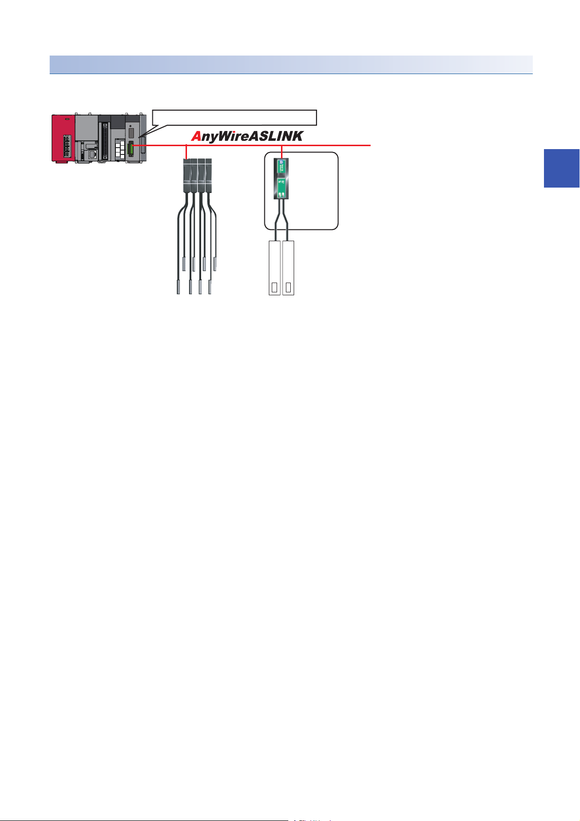
Example of a data restoration
AnyWireASLINK master module start I/O number 30
Address 1 to 4
ID513 (201H) to
ID516 (204H)
Address 5
ID517 (205H)
Restoration target
■Example of a system configuration
The following shows the example of a system configuration for data restoration.
• Target module type: AnyWireASLINK
• Execution unit: ID
• Folder number setting: 12
• Target device (target module): Start I/O No.30
• Target device (ID number): Address 5, ID517 (205H)
• Operation setting on error: Stop
3
3 AnyWireASLINK
3.5 Backing up/Restoring Data of Devices Supporting iQSS
49
Page 52

■Devices used in the program
Device Description Value
M0 Initialization trigger
M1000 Restoration execution trigger
M1100 Restoration right-to-use request trigger
M1200 Restoration right-to-use confirmation trigger
M1300 Restoration setting/start trigger
M2000 Restoration execution cancellation trigger
M3000 Restoration execution normal completion display
M3500 Restoration execution abnormal completion display
M3550 Restoration right-to-use acquisition failure
D1000 Right-to-use number storage area
D5000 Restoration number of normally completed devices
D5001 Restoration number of devices completed with an error
D5002 Restoration error cause in a module
D5003 Restoration error cause in a device
SM1435 Restoration execution enabled
SM1439 Restoration request
SM1442 Restoration cancellation request
SD1435 Restoration use request 1020H
SD1436 Restoration right-to-use acquisition status
SD1437 Restoration target module/execution unit setting Lower 8 bits: 1H
SD1438 Restoration folder number setting 12
SD1439 Restoration target setting (target module) 3H
SD1440 Restoration target setting (target device 1) 517
SD1444 Operation setting when a data restoration error occurs 1H
SD1446 Restoration execution status
SD1448 Restoration number of normally completed devices
SD1449 Restoration number of devices completed with an error
SD1452 Restoration error cause in a module
SD1453 Restoration error cause in a device
X30 Module READY
X31 DP/DN short error
X33 Transmission cable voltage drop error
X34 DP/DN disconnection error
X40 Slave module alarm signal
X41 Parameter access completion flag
X42 Parameter access error
X44 Automatic address detection flag
Upper 8 bits: 2H
50
For details on special relays (SM) and special registers (SD) to be used and their setting ranges, refer to the
following section.
Page 355 Special Relay (SM)/Special Register (SD) List
3 AnyWireASLINK
3.5 Backing up/Restoring Data of Devices Supporting iQSS
Page 53

■Sample program
0
M0
FMOV K0 D5000 K4
RST M3000
RST M3500
SET M1000
8
M1000
X30 X31 X33 X34 X40 X41 X42 X44
SET M1100
18
M1100
= H0 SD1436 MOV H1020 D1000
MOV D1000 SD1435
SET M1200
27
M1200
= D1000 SD1436 SET M1300
<> D1000 SD1436 <> H0 SD1436 SET M3550
41
M1300
MOV H201 SD1437
MOV K12 SD1438
MOV H3 SD1439
MOV K517 SD1440
MOV H1 SD1444
SET SM1439
53 = H3 SD1446 SET M3000
MOV SD1448 D5000
59 = H0FF SD1446 SET M3500
MOV SD1449 D5001
MOV SD1452 D5002
MOV SD1453 D5003
69
M3000
SET SM1435
M3500
RST M0
RST M1000
RST M1100
RST M1200
RST M1300
77
M2000
= H1 SD1446 SET SM1442
= H2 SD1446
86 END
3
3.5 Backing up/Restoring Data of Devices Supporting iQSS
3 AnyWireASLINK
51
Page 54

[Initialization]
(0) Initialize the execution result.
Initialize the normal completion display.
Initialize the abnormal completion display.
Set the restoration execution trigger.
[Executing data restoration]
(8) Set the restoration right-to-use request trigger.
[Requesting restoration right to use]
(18) Store the right-to-use number.
Set the restoration right-to-use request trigger.
Set the restoration right-to-use confirmation trigger.
[Checking restoration right to use]
(27) Set the restoration setting/start trigger.
Display the right-to-use acquisition failure.
[Setting/Starting data restoration]
(41) Set the target module/execution unit.
Set the target folder number.
Set the target module.
Set the target device 1.
Set the operation setting when a data restoration error occurs.
Set the restoration request.
[Checking data restoration execution]
(53) Display the normal completion.
Save the number of normally completed devices.
(59) Display the abnormal completion.
Save the number of devices completed with an error.
Save the error code (module error).
Save the error code (device error).
[Enabling the next data restoration process]
(69) Enable the data restoration execution.
Clear the initialization trigger.
Clear the restoration execution trigger.
Clear the restoration right-to-use request trigger.
Clear the restoration right-to-use confirmation trigger.
Clear the restoration setting/start trigger.
[Setting for cancelling the process]
(77) Set the restoration cancellation request.
52
3 AnyWireASLINK
3.5 Backing up/Restoring Data of Devices Supporting iQSS
Page 55
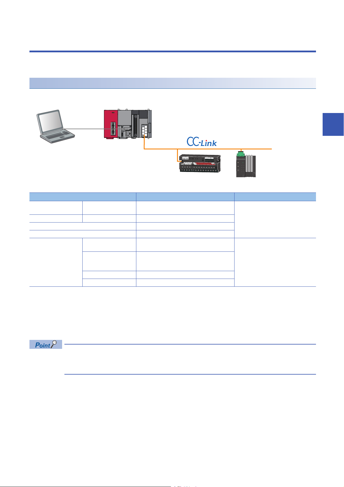
4 CC-Link
Engineering tool CPU module CC-Link master/local module
Analog input module (Voltage/current input) CC-Link Sensor supporting iQSS
This chapter explains the operation methods when using iQ Sensor Solution functions for MELSEC-L series or Q series via
CC-Link.
System configuration
This section explains the iQ Sensor Solution functions for CC-Link using the following system configuration.
Type Model name Manufacturer
Engineering tool GX Works2 SWnDND-GXW2 and SWnDNC-GXW2 ('n' indicates
its version.)
CPU module LCPU L26CPU-BT
CC-Link master/local module LJ61BT11
Analog input module (Voltage/current input) AJ65SBT2B-64AD
CC-Link sensor supporting
iQSS
For details on the devices supporting iQSS and the iQ Sensor Solution functions available for CC-Link, refer to the following
section.
Page 325 Devices that Support iQ Sensor Solution
For information on the engineering tools available for iQ Sensor Solution and the versions of engineering tools supporting
each iQ Sensor Solution function, refer to the following section.
Page 337 Engineering Tool and Version List
Communication unit for
CC-Link
Head-separated dual
display digital pressure
sensor
Digital fiber sensor FX-501
Digital laser sensor LS-403
SC-GU3-01 Panasonic Industrial Devices SUNX Co.,
DPS-401
Mitsubishi Electric Corporation
Ltd.
4
Before using each iQ Sensor Solution function, complete the installation and wiring of the actual system
configuration, and set network parameters and other settings required for communication with a device
supporting iQSS.
4 CC-Link
53
Page 56
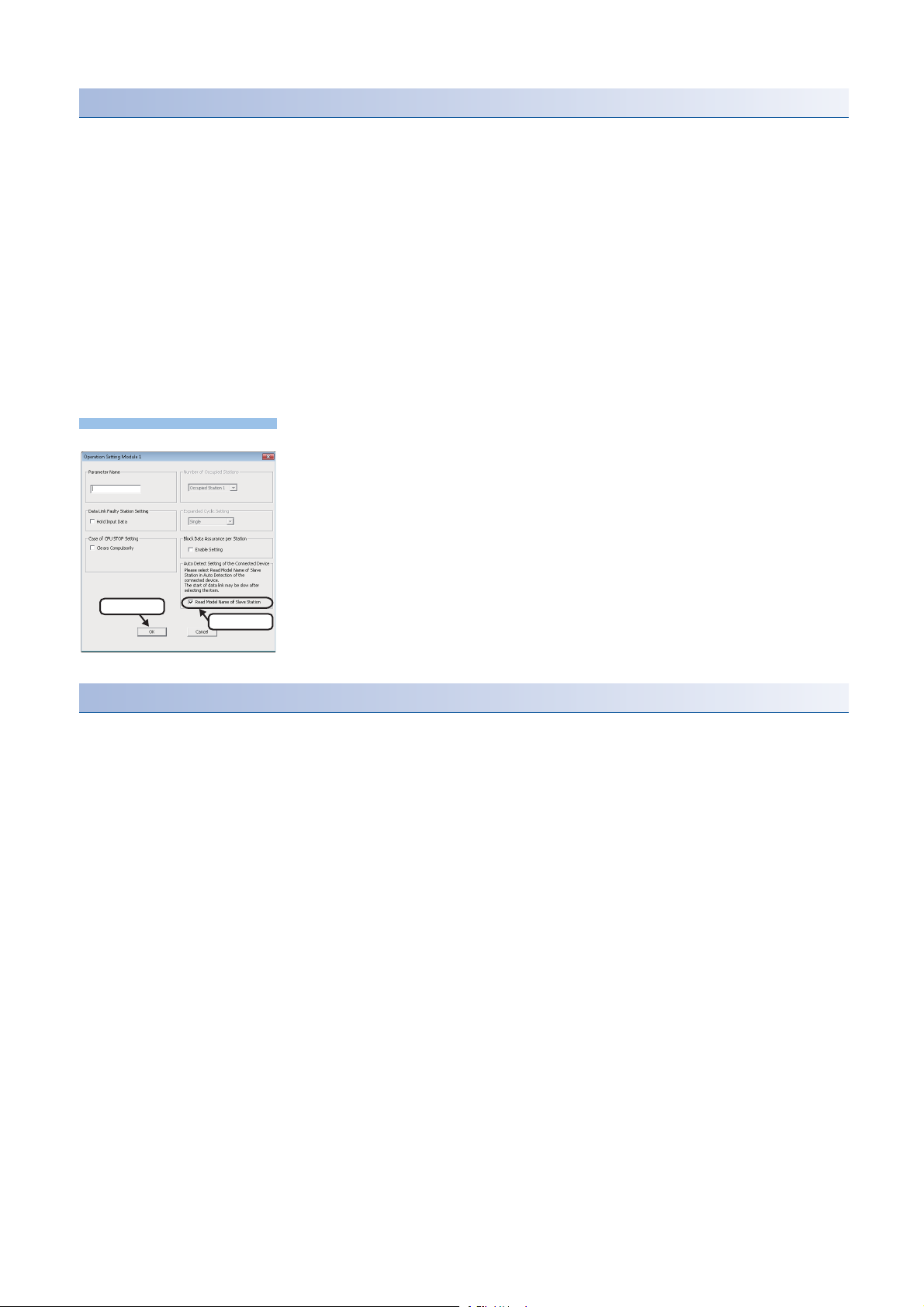
Before using iQ Sensor Solution functions
Operating procedure
2. Click
1. Check
■Setting refresh devices (network parameter)
Some iQ Sensor Solution functions cannot be performed if devices to refresh the data of remote input (RX), remote output
(RY), remote register (RWr), and remote register (RWw) are not set.
Set devices used to data refresh in advance.
For setting devices used to data refresh, refer to the following manuals.
• MELSEC-Q CC-Link System Master/Local Module User's Manual
• MELSEC-L CC-Link System Master/Local Module User's Manual
■Checking if "Read Model Name of Slave Station" is selected
The model name of a slave station can be read by selecting the "Read Model Name of Slave Station" checkbox.
Check if "Read Model Name of Slave Station" is selected in advance.
If the checkbox is not selected, write data to a CPU module in accordance with the following operating procedure before
performing an iQ Sensor Solution function.
For details on the display methods of the "Network Parameter - CC-Link Module
Configuration" screen, refer to the following manual.
GX Works2 Version 1 Operating Manual (Common)
1. Click the [Operation Setting] button on the "Network Parameter - CC-Link Module
Configuration" screen.
2. Select "Read Model Name of Slave Station" on the "Operation Setting" screen,
and click the [OK] button.
3. Click the [End] button, and select [Online] [Write to PLC].
4. Power OFF to ON or reset the CPU module.
Including a device connected to a communication module as a target
Some or all remote registers of a target device are used in a system while performing an iQ Sensor Solution function.
Therefore, add "Remote register use prohibited status (SW0160 to SW0163)" to the interlock when creating a program.
54
4 CC-Link
Page 57

Considerations when detecting devices supporting iQSS
■Station numbers of slave stations are not sequential
When an automatic detection of connected devices is performed in a system configuration in which the station numbers of
slave stations are not sequential, a general-purpose remote I/O station is automatically set for a station without a station
number as a reserved station.
Arrange the stations and change the modules in accordance with the actual module configuration.
■"General Module" is displayed
After performing an automatic detection of connected devices, a reserved station and a station which is not included in the
network parameter are displayed as "General Module".
In that case, turn the power OFF, and ON again in the order from the slave station to the master station. Then, perform an
automatic detection of connected devices again.
■A system configuration is changed
When a system configuration is changed (stations are added or changed), a slave station may not be detected.
In that case, turn the power OFF, and ON again in the order from the slave station to the master station. Then, perform an
automatic detection of connected devices again.
■A standby master station is included in a system configuration
When a standby master station is included in a system configuration, the last station number is set for the station.
Change the station number in accordance with the actual system configuration.
■The operation is switched from the standby master operation to the master operation
When the standby master operation is switched to the master operation, a station whose operation is switched to the master
operation will not be detected.
In that case, turn the power OFF, and ON again in the order from the standby master station to the master station. Then,
perform an automatic detection of connected devices again.
4
■Automatic refresh parameters is not set
The following iQ Sensor Solution functions cannot be performed if the automatic refresh parameters (remote input (RX),
remote output (RY), remote register (RWr), and remote register (RWw)) are not set.
• Automatic detection function of a device supporting iQSS which is connected to a bridge module
• Sensor parameter read/write function
Write the automatic refresh parameters to a CPU module before performing an iQ Sensor Solution function.
For details on the automatic refresh parameters, refer to the following manuals.
• MELSEC-Q CC-Link System Master/Local Module User's Manual
• MELSEC-L CC-Link System Master/Local Module User's Manual
■"Read Model Name of Slave Station" checkbox is not selected
The following iQ Sensor Solution functions cannot be performed because the model name of a slave station cannot be read
unless "Read Model Name of Slave Station" on the "Operation Setting" screen is selected.
• Automatic detection of connected devices, verification of connected devices and configurations
• Sensor/device monitor
"General CC-Link module" is displayed on the "Sensor/Device Monitor for CC-Link" screen.
• Data backup/restoration
Select "Read Model Name of Slave Station", and write data to a CPU module before performing an iQ Sensor Solution
function.
When selecting "Read Model Name of Slave Station", refer to the following section.
Page 54 Checking if "Read Model Name of Slave Station" is selected
4 CC-Link
55
Page 58

4.1 Detecting Devices Supporting iQSS Automatically
Operating procedure
Select
1. Select 4. Check
3. Click
2.Enter
Click
A slave station connected to a CC-Link master/local module can be detected and the information can be displayed in the "CCLink Configuration" window.
For the creation method of a new project and the operation methods of the "CC-Link Configuration" window, refer to the
following manual.
GX Works2 Version 1 Operating Manual (Common)
1. Create a new project in an engineering tool.
2. Select "Parameter" "Network Parameter" "CC-Link" on
the Project view.
3. Select and enter necessary parameters on the "Network
Parameter - CC-Link Module Configuration" screen.
Check that "Read Model Name of Slave Station" is
selected on the "Operation Setting" screen.
Page 54 Checking if "Read Model Name of
Slave Station" is selected
4. Select "Set the station information in the "CC-Link
configuration" window".
5. Read the message and click the [Yes] button.
The [Station Information] button of "Station Information Setting" is
changed to [CC-Link Configuration Setting] button.
6. Click the [CC-Link Configuration Setting] button.
56
4 CC-Link
4.1 Detecting Devices Supporting iQSS Automatically
Page 59

7. Select [CC-Link Configuration] [Online] [Detect Now] in
Select
1. Check
2. Click
List of stations
Device map area
Output window
Select
the "CC-Link Configuration" window.
8. Read the message and select the "Set the Module
Connected to the Communication Module also as the Read
Object" checkbox, then click the [Yes] button.
In any of the following cases, select the "Set the Module
Connected to the Communication Module also as the Read
Object" checkbox.
• The automatic detection function of connected devices is used
for the first time.
• The CPU module was reset or turned OFF.
• The actual system configuration was changed.
The actual system configuration is displayed in the "CC-Link
Configuration" window.
4
9. Select [CC-Link Configuration] [Close with Reflecting the
Setting] in the "CC-Link Configuration" window.
The setting in the "CC-Link Configuration" window is applied to the
network parameter and completed.
4 CC-Link
4.1 Detecting Devices Supporting iQSS Automatically
57
Page 60

• Once an automatic detection of connected devices is performed, the mode setting and the transmission rate
which have been set in a CC-Link master/local module are also detected.
• The system configuration cannot be detected if an error occurs on the master station.
Take the corrective actions and perform an automatic detection of connected devices again.
• Error information is displayed in the "Output" window when an error occurred.
Double-click it and correct the error at the jumped destination.
• When a module which is not a device supporting iQSS is detected, it is displayed as shown below:
"Module with No Profile Found"
"General Module"
• When "Module with No Profile Found" is displayed, it can be changed to "General CC-Link Module" by the
following operation:
Select the target module, and select [CC-Link Configuration] [Change Module] [Change to General
CC-Link Module].
• When the automatic CC-Link startup is used, power OFF to ON or reset the CPU module after writing the
data to a CPU module. By performing automatic detection of connected devices again, the model name of a
slave station can be read.
For details on the automatic CC-Link startup, refer to the following manuals.
(MELSEC-Q CC-Link System Master/Local Module User's Manual)
(MELSEC-L CC-Link System Master/Local Module User's Manual)
■Detection methods of a system configuration
The system configuration of CC-Link can also be detected by either of the following operations.
• Click the [Detect Now] button in the "CC-Link Configuration" window.
• Select [Online] [Detect Now] in MELSOFT Navigator.
For the operation methods of MELSOFT Navigator, refer to the following manual.
(Let's start iQ Works Version 2)
58
4 CC-Link
4.1 Detecting Devices Supporting iQSS Automatically
Page 61

Detecting devices connected to a bridge module (NZ2AW1C2AL)
CPU module CC-Link master/local module
ASLINKAMP (Input) ASLINKER (Input)
CC-Link-AnyWireASLINK bridge module
To display devices supporting iQSS, which are connected to a bridge module (NZ2AW1C2AL), on a system configuration
diagram, first a bridge module (NZ2AW1C2AL) needs to be detected in the "CC-Link Configuration" window. Then, perform an
automatic detection of connected devices in the "AnyWireASLINK Configuration" window in order to detect and display
devices supporting iQSS which are connected to a bridge module (NZ2AW1C2AL).
For the considerations when detecting devices supporting iQSS connected to a bridge module (NZ2AW1C2AL), refer to the
following section.
Page 61 Considerations when detecting devices connected to a bridge module
System configuration
4
Type Model name Manufacturer
CPU module LCPU L26CPU-BT Mitsubishi Electric Corporation
CC-Link master/local module LJ61BT11
CC-Link-AnyWireASLINK bridge module NZ2AW1C2AL
ASLINKAMP (Input) Photoelectric sensor B289SB-01AP-CAM20 (ASLINKAMP master)
Fiber sensor B289SB-01AF-CAS (ASLINKAMP slave)
ASLINKER (Input) B281SB-02U-CC20
■Setting the operation mode for CC-Link Ver.2-compatible slave station
A bridge module (NZ2AW1C2AL) is a CC-Link Ver.2-compatible slave station.
To detect and display a bridge module (NZ2AW1C2AL) on a system configuration diagram, set the operation mode in which
CC-Link Ver.2-compatible slave station works.
The following table shows the combinations of the parameter setting for a CC-Link master/local module and the CC-Link
operation mode for a bridge module (NZ2AW1C2AL).
CC-Link master/local module (L26CPU-BT, L26CPU-PBT, LJ61BT11, QJ61BT11N) Bridge module (NZ2AW1C2AL)
Parameter setting item CC-Link operation mode
Mode Station information (station type)
Remote net Ver.2 mode Ver.2 remote device station Ver.2.00
Remote net additional mode
For the information of the version and mode of CC-Link, refer to the following manuals.
• MELSEC-Q CC-Link System Master/Local Module User's Manual
• MELSEC-L CC-Link System Master/Local Module User's Manual
• CC-Link-AnyWireASLINK Bridge Module User's Manual
B289SB-01AP-CAS (ASLINKAMP slave)
AnyWire Corporation
B289SB-01AF-CAS (ASLINKAMP slave)
4 CC-Link
4.1 Detecting Devices Supporting iQSS Automatically
59
Page 62

Operating procedure
1. Detect and display a bridge module (NZ2AW1C2AL) in the
1. Select
2. Check
3. Click
2. Select
1. Select
Select
1. Check
2. Click
"CC-Link Configuration" window.
For the method for detecting and displaying a bridge module
(NZ2AW1C2AL) automatically in the "CC-Link Configuration"
window, refer to the following section.
Page 61 Detection method of a system configuration
2. Select a bridge module (NZ2AW1C2AL) in 'List of stations' or
'Device map area' in the "CC-Link Configuration" window, and
select [CC-Link Configuration] [Open System
Configuration] [Open AnyWireASLINK Configuration].
3. Select [AnyWireASLINK Configuration] [Online] [Detect
Now] in the "AnyWireASLINK Configuration" window.
4. When an automatic address detection is required, select the
"Execute Detect Now after Address Auto-recognition"
checkbox, then click the [Yes] button.
For a case in which an automatic address detection is required,
refer to the following manual.
CC-Link-AnyWireASLINK Bridge Module User's Manual
60
4 CC-Link
4.1 Detecting Devices Supporting iQSS Automatically
Page 63

The device supporting iQSS, which is connected to a bridge
Select
module (NZ2AW1C2AL), is displayed in the "AnyWireASLINK
Configuration" window.
5. Select [AnyWireASLINK Configuration] [Close with
Enabling the Setting] in the "AnyWireASLINK Configuration"
window.
The setting of the "AnyWireASLINK Configuration" window is
enabled and the window is closed.
■Detection method of a system configuration
A system configuration of a device supporting iQSS, which is connected to a bridge module (NZ2AW1C2AL), can also be
detected by either of the following operations.
• Click the [Detect Now] button in the "AnyWireASLINK Configuration" window.
Considerations when detecting devices connected to a bridge module
■Address setting for a device supporting iQSS
To use an iQ Sensor Solution function in a device supporting iQSS which is connected to a bridge module (NZ2AW1C2AL),
set the setting required for communication (such as address setting and amplifier teaching) in advance.
Make sure that the address occupied by a device supporting iQSS is set so as not to exceed the number of transmission
points set for a bridge module (NZ2AW1C2AL).
(CC-Link-AnyWireASLINK Bridge Module User's Manual)
4
4 CC-Link
4.1 Detecting Devices Supporting iQSS Automatically
61
Page 64
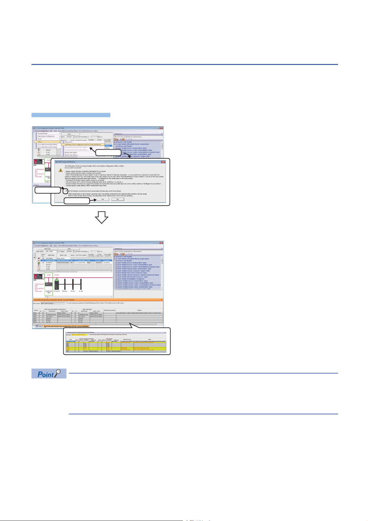
4.2 Verifying Devices Supporting iQSS Against
Operating procedure
1. Select
2. Check
3. Click
System Configuration
The system configuration displayed in the "CC-Link Configuration" window can be verified against the slave stations
connected to a CC-Link master/local module.
The result is displayed in the "Verification Result of the Configuration with the Connected Module" window.
Verify a system configuration when it is manually created or edited.
1. Select [CC-Link Configuration] [Online] [Verification of
the Configuration with the Connected Module] in the "CC-Link
Configuration" window.
2. Read the message and select the "Set the Module
Connected to the Communication Module also as the Read
Object" checkbox, then click the [Yes] button.
In any of the following cases, select the "Set the Module
Connected to the Communication Module also as the Read
Object" checkbox.
• The verification function of connected devices and
configurations is used for the first time
• The CPU module was reset or turned OFF.
• The actual system configuration was changed.
The verification results are displayed in the "Verification Result of
the Configuration with the Connected Module" window.
■Verification methods of system configuration information
The system configuration information of CC-Link can also be verified by either of the following operations.
• Click the [Verify] button in the "CC-Link Configuration" window.
• Select [Online] [Verification of the Configuration with the Connected Module] in MELSOFT Navigator.
For the operation methods of MELSOFT Navigator, refer to the following manual.
(Let's start iQ Works Version 2)
62
4 CC-Link
4.2 Verifying Devices Supporting iQSS Against System Configuration
• The display is switched by right-clicking on the "Verification Result of the Configuration with the Connected
Module" window and selecting "Display All"/"Display Mismatch Only"/"Display other than Match".
• The cursor jumps to the corresponding location in the "CC-Link Configuration" window by double-clicking
the row with "Mismatch" in the "Verification Result of the Configuration with the Connected Module" window.
Page 65

■Verification method of a device supporting iQSS which is connected to a bridge module
Operating procedure
(NZ2AW1C2AL)
The system configuration of a device supporting iQSS, which is connected to a bridge module (NZ2AW1C2AL), can also be
verified by the following operation.
1. Select a bridge module (NZ2AW1C2AL) in 'List of stations' or 'Device map area' in the "CC-Link Configuration" window.
2. Select [CC-Link Configuration] [Open System Configuration] [Open AnyWireASLINK Configuration].
3. Select [AnyWireASLINK Configuration] [Online] [Verification of the Configuration with the Connected Module] in the
"AnyWireASLINK Configuration" window.
4
4 CC-Link
4.2 Verifying Devices Supporting iQSS Against System Configuration
63
Page 66
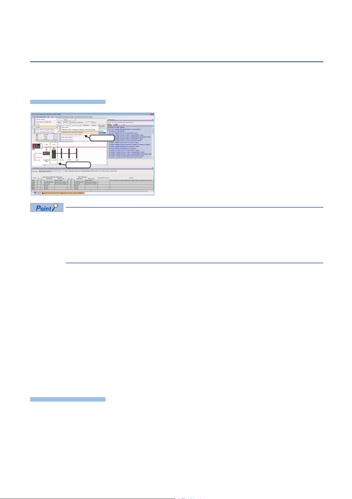
4.3 Reading/Writing Parameters from/to Devices
Window
Operating procedure
2. Select
1. Select
Supporting iQSS
Parameters can be read from and written to a slave station.
For the operation methods of the "CC-Link Configuration" window, refer to the following manual.
GX Works2 Version 1 Operating Manual (Common)
1. Select a target device supporting iQSS in 'List of stations' or
'Device map area' in the "CC-Link Configuration" window,
and select [CC-Link Configuration] [Online] [Parameter
Processing of Slave Station].
2. Read/write the parameters on the "Parameter Processing of
Slave Station" screen.
• When using a CC-Link master/local module (QJ61BT11N), the parameters of inverters (FR-A720 series and
FR-A740 series) can be read/written.
• The data backup/restoration function is useful to read/write the parameters of multiple devices supporting
iQSS in a batch. (Page 68 Backing up/Restoring Data of Devices Supporting iQSS)
• The useful functions (linkage with dedicated tools, and command execution to slave stations) can also be
used in the "CC-Link Configuration" window. (Page 323 Useful Functions)
■Display methods of the "Parameter Processing of Slave Station" screen
The "Parameter Processing of Slave Station" screen can also be displayed by any of the following operations.
• Select a target module in 'List of stations' or 'Device map area' in the "CC-Link Configuration" window, then right-click and
select [Online] [Parameter Processing of Slave Station] from the shortcut menu.
• Select a target module in 'List of stations' or 'Device map area' on the "Sensor/Device Monitor for CC-Link" screen, and
select [Online] [Parameter Processing of Slave Station].
• Select a target module in 'List of stations' or 'Device map area' on the "Sensor/Device Monitor for CC-Link" screen, then
right-click and select [Parameter Processing of Slave Station] from the shortcut menu.
For details on the "Sensor/Device Monitor for CC-Link" screen, refer to the following section.
Page 66 Monitoring Devices Supporting iQSS
■Display method of a device supporting iQSS, which is connected to a bridge module
(NZ2AW1C2AL) on the "Parameter Processing of Slave Module" screen
A device supporting iQSS, which is connected to a bridge module (NZ2AW1C2AL), can be displayed on the "Parameter
Processing of Slave Module" screen by the following operation.
1. Select a bridge module (NZ2AW1C2AL) in 'List of stations' or 'Device map area' in the "CC-Link Configuration" window.
2. Select [CC-Link Configuration] [Open System Configuration] [Open AnyWireASLINK Configuration].
3. Select a target device supporting iQSS in 'List of modules' or 'Device map area' in the "AnyWireASLINK Configuration"
window, and select [AnyWireASLINK Configuration] [Online] [Parameter Processing of Slave Module].
64
4 CC-Link
4.3 Reading/Writing Parameters from/to Devices Supporting iQSS
Page 67
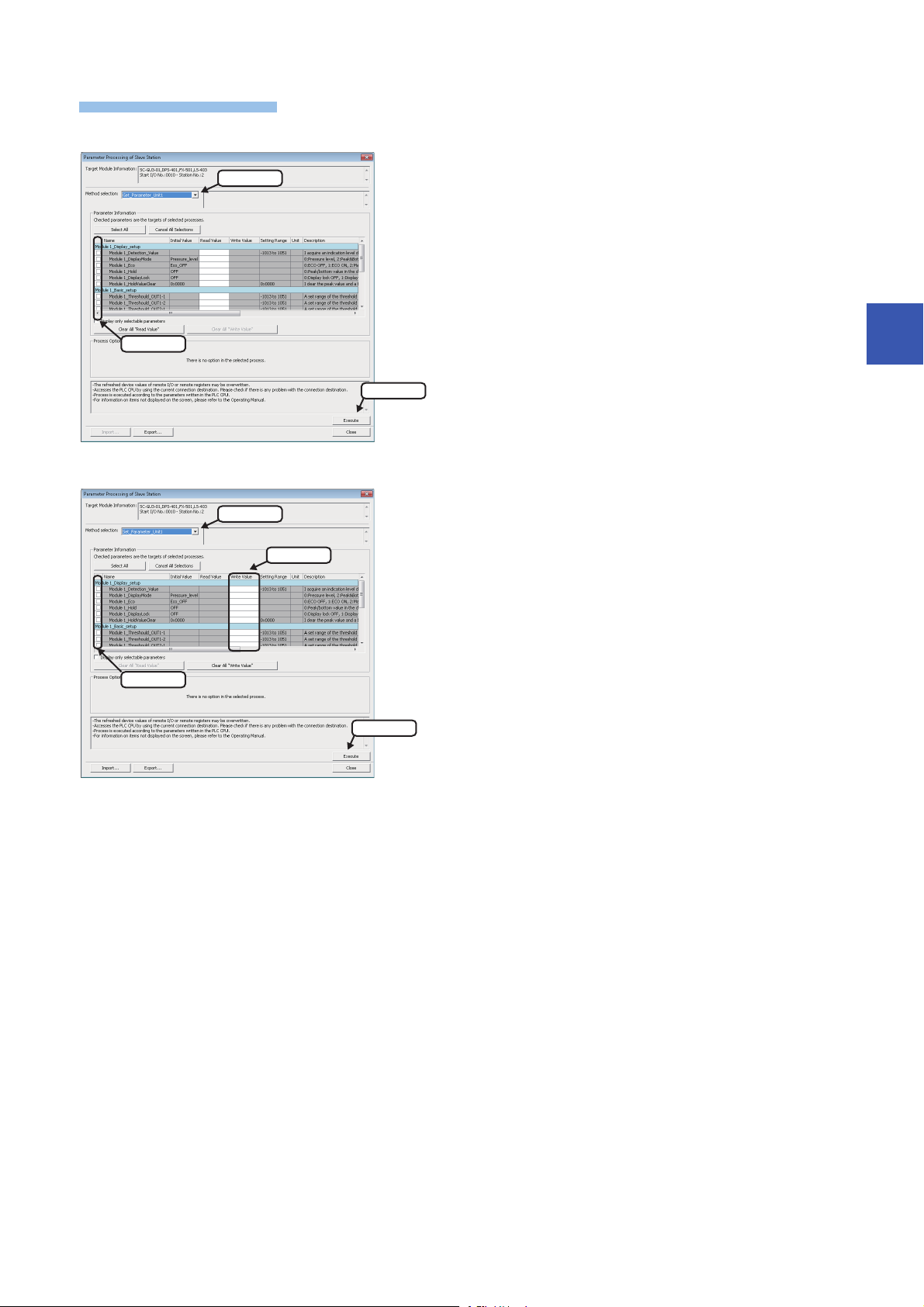
Operating procedure
■Reading parameters
1. Select
2. Check
3. Click
1. Select
3. Enter
2. Check
4. Click
■Writing parameters
1. Select "Parameter read".
2. Select a parameter to be read.
3. Click the [Execute] button.
The selected parameter is read and the value is displayed in the
column of "Read Value".
4
1. Select "Parameter write".
2. Select a parameter to be written.
3. Enter a value in the column of "Write Value".
4. Click the [Execute] button.
The value entered in the column of "Write Value" is written to the
device supporting iQSS.
4 CC-Link
4.3 Reading/Writing Parameters from/to Devices Supporting iQSS
65
Page 68
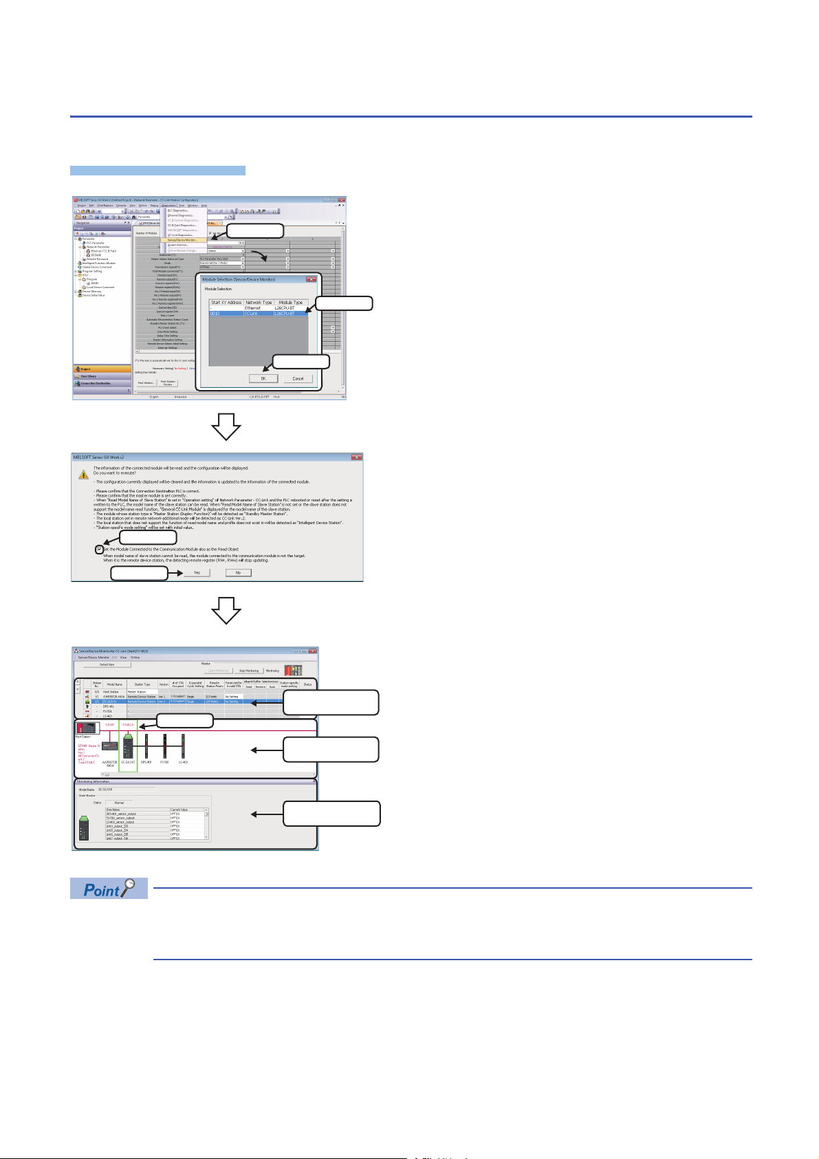
4.4 Monitoring Devices Supporting iQSS
Operating procedure
1. Select
2. Select
3. Click
1. Check
2. Click
List of stations
Device map area
Monitoring Information
window
Select
The connection statuses of devices supporting iQSS can be monitored.
1. Select [Diagnostics] [Sensor/Device Monitor] with an
engineering tool.
2. Select a CC-Link master/local module in the "Module
Selection (Sensor/Device Monitor)" screen, and click the [OK]
button.
3. Read the message and select the "Set the Module
Connected to the Communication Module also as the Read
Object" checkbox, then click the [Yes] button.
In any of the following cases, select the "Set the Module
Connected to the Communication Module also as the Read
Object" checkbox.
• The automatic detection function of connected devices is used
for the first time.
• The CPU module was reset or turned OFF.
• The actual system configuration was changed.
The "Sensor/Device Monitor for CC-Link" screen appears.
4. Select a target device supporting iQSS to be monitored in
'List of stations' or 'Device map area' in the "Sensor/Device
Monitor for CC-Link" screen.
The status of the selected device supporting iQSS is displayed in
the "Monitoring Information" window.
Sensor/device monitor reads a large volume of information from a CPU module at once.
Therefore, the processing speed of the sensor/device monitor function may decrease depending on the set
communication route.
66
4.4 Monitoring Devices Supporting iQSS
4 CC-Link
Page 69

■Display method of a device supporting iQSS, which is connected to a bridge module
Operating procedure
(NZ2AW1C2AL) on the "Sensor/Device Monitor for CC-Link" screen
A device supporting iQSS, which is connected to a bridge module (NZ2AW1C2AL), can be displayed on the "Sensor/Device
Monitor for CC-Link" screen by the following operation.
1. Select a bridge module (NZ2AW1C2AL) in 'List of stations' or 'Device map area' on the "Sensor/Device Monitor for CC-
Link" screen.
2. Select [Sensor/Device Monitor] [Open System Configuration] [Open AnyWireASLINK Configuration].
4
4 CC-Link
4.4 Monitoring Devices Supporting iQSS
67
Page 70
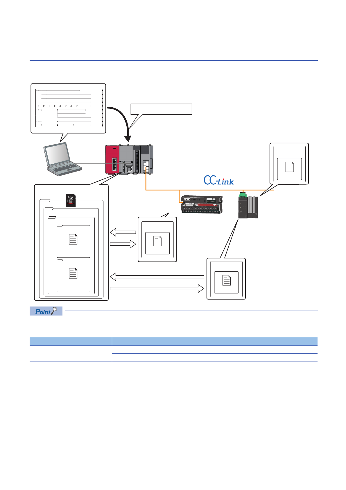
4.5 Backing up/Restoring Data of Devices Supporting
0001_0002
0001_0001
iQSS
CC-Link
20141211_15
0
M0
FMOV K0 D5000 K4
RST M3000
RST M3500
SET M1000
69
M1000 X10 X1F X11 SW80.0 SW80.1 SW160.0 SW160.1
SET M1100
114
M1100
= H0 SD1436 MOV H1030 D1000
MOV D1000 SD1435
SET M1200
181
M1200
= D1000 SD1436 SET M1300
<> D1000 SD1436 <> H0 SD1436 SET M3550
Data backup/restoration
command
Station sub-ID 1
Setting data
SD memory card
Station No.2
Station No. 1
Data backup
Station No. 1
Setting data of
station No. 1
Setting data
Data restoration
Station No.2
Data backup
Setting data of
station No.2
Setting data
Data restoration
iQSS
Backing up the information of a device supporting iQSS to an SD memory card and restoring it to a module simplifies the
setting change for changeover.
Function Reference
Data backup Page 74 Data backup
Data restoration Page 86 Data restoration
In such a case as limited production of diversified products, the data backup/restoration function is useful for
switching multiple sensor settings from for product A to for product B in a batch.
Page 75 Program execution for data backup
Page 87 Program execution for data restoration
68
4 CC-Link
4.5 Backing up/Restoring Data of Devices Supporting iQSS
Page 71
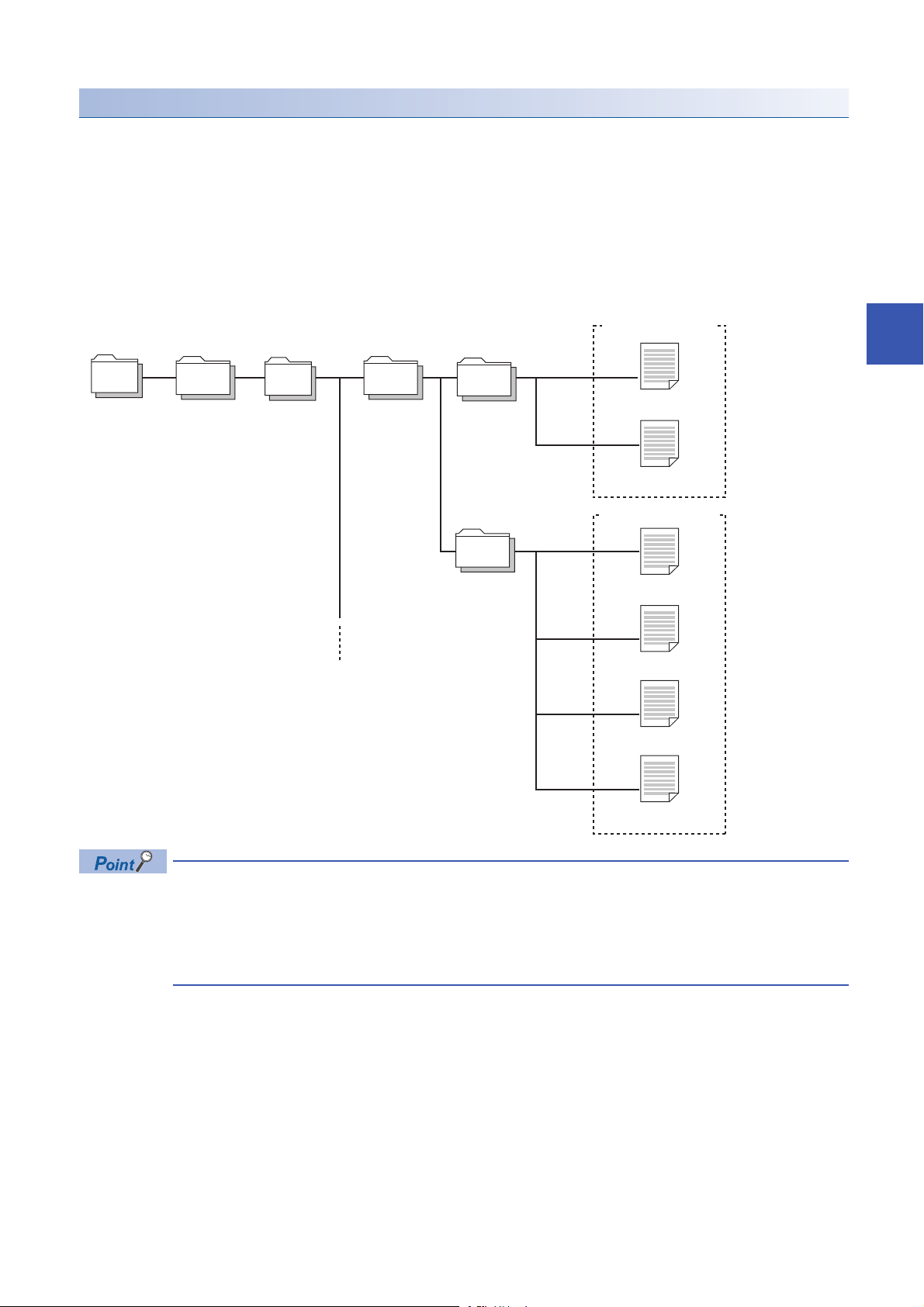
Backup folder/file
/
iQSS CC-Link
20141211_15
0001_ 0001
0001_ 0002
1) Backup folder
(Date_Number)
Maximum of 100
2) Backup folder
(I/O number_Station
number)
Backup data
(Station number)
Root directory
3) STATION0001.QBR
(Backup file)
SSBRINF.QSI
(System file)
Backup data
(Station sub-ID number)
4) SUBID0001.QBR
(Backup file)
4) SUBID0002.QBR
(Backup file)
4) SUBID0003.QBR
(Backup file)
SSBRINF.QSI
(System file)
Backup data is created in the 'iQSS' folder in the root directory when backing up the data.
If no 'iQSS' folder exists when backing up the data, an 'iQSS' folder will be newly created.
Up to 100 backup folders (date_number) can be created in the 'CC-Link' folder.
Do not change a backup folder name, configuration or saved file. Otherwise, data may not be restored properly.
For the backup file capacity, refer to the following section.
Page 368 Backup File Capacity
■Backup folder configuration
The following figure shows the backup folder configuration in an SD memory card.
4
When backing up the data of a device supporting iQSS, which is connected to a bridge module
(NZ2AW1C2AL):
• Backup data is stored in the 'CC-Link' backup folder.
• The station sub-ID number is the same ID number as the AnyWireASLINK address ID.
• The backup file (STATION0000.QBR) of the bridge module is not created.
4 CC-Link
4.5 Backing up/Restoring Data of Devices Supporting iQSS
69
Page 72

■Backup folder name
2014 12 11 15
Arbitrary number (2-digit (00 to 99) decimal)
Backup date (2-digit decimal)
Backup month (2-digit decimal)
Backup year (4-digit decimal)
0001 0001
Station number (4-digit decimal)
CC-Link master/local module start I/O number (4-digit hexadecimal) (A value of start I/O number divided by 16)
STATON0001.QBR
Station number (4-digit decimal)
SUBID0001.QBR
Station sub-ID number (4-digit decimal)
1) Date_Number
2) Start I/O number_Station number
■Backup file name
3) Station number
4) Station sub-ID number
70
4 CC-Link
4.5 Backing up/Restoring Data of Devices Supporting iQSS
Page 73

Points to be checked before data backup/restoration
■Check the availability of data backup/restoration
The data can be backed up and restored when a CC-Link master/local module and a bridge module (NZ2AW1C2AL) satisfy
the following conditions.
Perform the automatic address detection function and the parameter batch read function before data backup/restoration.
The 'n' indicates the address assigned to the master station by the station number setting.
Module Condition to be checked Remote device RX signal Signal status
CC-Link master/local module Module error Xn0 OFF
Module READY XnF ON
Host station data link status Xn1 ON
Other station data link status
Remote register use prohibited status
Bridge module (NZ2AW1C2AL)
(CC-Link operation mode Ver.2.00)
*1 Set the target station.
*2 Excluding when the error code is 0131H.
Remote READY RX(n+D)B ON
DP/DN short error RXn1 OFF
Transmission cable voltage drop error RXn3 OFF
DP/DN disconnection error RXn4 OFF
Slave module alarm signal RX(n+1)0 OFF
Parameter access completion flag RX(n+1)1 ON
Parameter access error RX(n+1)2 OFF
Automatic address detection flag RX(n+1)4 OFF
*1
SW0080 to SW0083 OFF
*1
SW0160 to SW0163 OFF
*2
4
■The "Read Model Name of Slave Station" checkbox on the "Operation Setting" screen
Check that "Read Model Name of Slave Station" is selected on the "Operation Setting" screen before performing the data
backup/restoration function. If it is not selected, the data backup/restoration function cannot be performed.
For details on the "Read Model Name of Slave Station" checkbox on the "Operation Setting" screen, refer to the following
section.
Page 54 Checking if "Read Model Name of Slave Station" is selected
■Interlock setting
Some or all remote registers of a target device are used in the system during a data backup/restoration.
Therefore, add "Remote register use prohibited status (SW0160 to SW0163)" to the interlock when creating a program.
■The station whose operating status is switched from the standby master station to master
station
The data backup/restoration function cannot be performed to a station in which the operation was switched from the standby
master operation to the master operation.
In that case, turn the power OFF, and ON again in the order from the standby master station to the master station. Then,
perform a data backup/restoration.
Considerations for data backup/restoration
■Use of an SD memory card
• During a data backup or restoration, do not perform the following actions: turning OFF the power, resetting a module, and
inserting or removing an SD memory card.
Otherwise, the data backup or restoration will be interrupted and the data will not be backed up or restored properly.
• Normal backup data cannot be created if the memory size or the number of files exceeds the maximum storage capacity of
an SD memory card during a data backup.
■Operations with a display unit during data backup
4.5 Backing up/Restoring Data of Devices Supporting iQSS
4 CC-Link
71
Page 74

If any of the following operations are performed with a display unit during data backup, the operation will be completed
abnormally and the error is displayed on the display unit.
Operation name
Project data batch save/load function
File deletion on the "Memory card operation menu" screen of a display unit
72
4 CC-Link
4.5 Backing up/Restoring Data of Devices Supporting iQSS
Page 75

■Unavailable operations and functions at the same time as data backup
20141210_12
Do not change.
If any of the following operations and functions are performed during data backup, the backup will be completed abnormally
and the error cause is stored in SD1452 (iQ Sensor Solution backup/restoration error cause in a module).
The error is returned to the request source which performs the operation or function.
Operation/function name
Operation with an engineering tool Change TC setting
Operations with CPU Module Logging Configuration Tool Data logging function
Others Writing or deleting files using FTP or MC protocol
*1
Online change (ladder mode)
Online change (inactive block) for SFC program
Write to PLC (including writing data to the CPU module during RUN)
Write title
Password/keyword
• New (registration/change)
• Delete
• Disable
Format PLC memory
Clear PLC memory (Clear all file registers)
Arrange PLC memory
Delete PLC data
Write/delete PLC user data
Program memory batch download
CPU module change function with SD memory card
Sampling trace function
• Start trace
• Register trace
• Write to PLC
Writing protocol setting data to the CPU module (predefined protocol support function)
Project data batch save/load function
• Deleting/writing the data logging setting
• Stopping data logging operation
• Deleting data logging file(s)
File transfer function (FTP server) of the built-in Ethernet function
File transfer function (FTP client) of the built-in Ethernet function
Register/cancel display unit menu
CPU module data backup/restoration function
4
*1 Available operations and functions differ between LCPUs and QCPUs. For details, refer to the user's manual of a CPU module used.
When data is backed up or restored during a data logging, the performance of the data logging will be reduced.
Therefore, sampled data may be partially missed and the data missing frequency may be increased.
■Communication load
When data is backed up or restored, the load of the service processing is temporarily increased. Consequently, a timeout
error may occur in other communications.
To avoid a timeout error, review the value set for "Service Processing Setting" on the [PLC System] tab in "PLC parameter".
■Backup folder name
Do not change an underscore and a subsequent number of a backup folder name (date_number).
If they are changed, the data may not be restored properly.
4 CC-Link
4.5 Backing up/Restoring Data of Devices Supporting iQSS
73
Page 76

Data backup
Operating procedure
Operating procedure
2. Select
1. Select
Information of a device supporting iQSS can be saved in an SD memory card for each station by using an engineering tool.
1. Select a target device supporting iQSS in 'List of stations' or
'Device map area' in the "CC-Link Configuration" window, and
select [CC-Link Configuration] [Online] [Backup Slave
Station].
2. Read the message, and click the [Yes] or [OK] button.
Data is backed up.
The initial values of the backup setting (SD1438 and SD1444) are as follows:
• SD1438 (Folder number setting): FFFFH (automatic specification)
• Lower 8 bits of SD1444 (operation setting on error): 0H (continue)
Use a program when backing up data with the settings other than the one above. (Page 75 Program
execution for data backup)
■Other methods of data backup
Data can be backed up by the following methods.
• Select a target module in the 'List of stations' or 'Device map area' in the "CC-Link Configuration" window, then right-click
and select [Backup Slave Station] from the shortcut menu.
• Select a target module in the 'List of stations' or 'Device map area' on the "Sensor/Device Monitor for CC-Link" screen, then
right-click and select [Backup Slave Station] from the shortcut menu.
■Execution method of data backup for a device supporting iQSS which is connected to a
bridge module (NZ2AW1C2AL)
Data can be backed up for a device supporting iQSS, which is connected to a bridge module (NZ2AW1C2AL), by the
following method.
1. Select a bridge module (NZ2AW1C2AL) in 'List of stations' or 'Device map area' in the "CC-Link Configuration" window.
2. Select [CC-Link Configuration] [Open System Configuration] [Open AnyWireASLINK Configuration].
3. Select [AnyWireASLINK Configuration] [Online] [Backup Slave Module] in the "AnyWireASLINK Configuration"
window.
74
4 CC-Link
4.5 Backing up/Restoring Data of Devices Supporting iQSS
Page 77

Program execution for data backup
Operating procedure
Start
Acquiretherighttousespecialrelays/registers.
Completionofright-to-useacquisition
Setthesettingsfordatabackup.
Requestadatabackup.
Executionofdatabackup
Requestacancellationofbackupprocess.
Backuperror
Normalcompletionofbackupprocess
Cancellationofbackupprocess
Enablethenextbackupprocess.
Complete
Information of a device supporting iQSS can be backed up in an SD memory card with a program.
Page 76 Acquiring a right to use
Page 76 Setting the backup setting
Page 77 Performing a data backup
4
Page 77 Releasing the right to use
For details on special relays (SM) and special registers (SD), refer to the following section.
Page 355 Special Relay (SM)/Special Register (SD) List
Page 77 Requiring a data backup cancellation
4 CC-Link
4.5 Backing up/Restoring Data of Devices Supporting iQSS
75
Page 78

Execution method of data backup
The target device for data backup can be set with a program.
■Acquiring a right to use
Set a value within the range from 1000H to 1FFFH to SD1435.
Right to use for data backup
• Special relays (SM) and special registers (SD) are used for data backup.
• To prevent the same special relay (SM) and special register (SD) from being set at the same time, acquiring
a right to use of them for data backup is required.
• To acquire a right to use, specify a value which is not duplicate with values for other request sources to
SD1435, and check that the value set to SD1435 is stored to SD1436.
• Normal operation cannot be assured if the data backup function is performed without confirming the
acquisition of a right to use.
■Setting the backup setting
1. Setting a target module type
Set the target module type for data backup to the lower 8 bits of SD1437.
Target module type Description
2H: CC-Link Set the target module type.
2. Setting an execution unit
Set the unit of execution for data backup to the upper 8 bits of SD1437.
Execution unit Description
1H: Module unit Set this to specify all devices supporting iQSS which are connected to the CC-Link master/local module with the
2H: Station unit Set this to specify either of the following devices supporting iQSS which are connected to the CC-Link master/local
3H: Station sub-ID unit Set this to specify the device supporting iQSS with the specified station sub-ID number which is connected to the
specified start I/O number.
module with the specified start I/O number: device supporting iQSS with the specified station number or all devices
supporting iQSS which are connected to the module with the specified station number.
module with the specified station number among the devices supporting iQSS which are connected to the CC-Link IE
Field Network master/local module with the specified start I/O number.
3. Setting a number for a data backup folder name
Set the number for a backup folder name to SD1438.
Target folder Description
FFFFH: Automatic specification
(Default)
FFFEH: Automatic specification
(folder deletion supported)
00 to 99: Target folder specification Set the number for a backup folder name.
Use the smallest number for a new backup folder name among the unused numbers as the backup folder name.
An error occurs when unused number is no longer available due to such cases as the number of folders reached the
upper limit.
Use the smallest number for a new backup folder name among the unused numbers as the backup folder name.
The oldest folder is deleted and the number of the deleted folder is used for a new backup folder name when unused
number is no longer available due to such cases as the number of folders reached the upper limit.
When another folder with the same number exists, the operation will be as follows:
■For module unit
• The backup folder with the same number is deleted, and a new backup folder is created.
■For station unit or station sub-ID unit
• Data in the backup folder with the same number is overwritten.
76
4 CC-Link
4.5 Backing up/Restoring Data of Devices Supporting iQSS
Page 79

4. Setting a target device
• Setting a module
When '1H' (module unit) is set for the execution unit in the step of 'Setting the execution unit', set the start I/O number of a
target device for data backup to SD1439.
Target device (Module) Description
0 to FFH: Start I/O number When '1H' (module unit) is set for the execution unit, set the value obtained by dividing the start I/O number of a CC-
Link master/local module, which is connected to a target device supporting iQSS, by 16.
• Setting a station number
When '2H' (station unit) or '3H' (station sub-ID unit) is set for the execution unit in the step of 'Setting the execution unit', set
the station number of a target device for data backup to SD1440.
Target device (Station
number)
1 to 64: Station number When '2H' (station unit) or '3H' (station sub-ID unit) is set for the execution unit, set the station number of a target
• Setting a station sub-ID number
When '3H' (station sub-ID unit) is set for the execution unit in the step of 'Setting the execution unit', set the station sub-ID
number of a target device for data backup to SD1441.
Target device (Station sub-ID
number)
0 to 9999: Station sub-ID number When '3H' (station sub-ID unit) is set for the execution unit, set the station sub-ID number of a target device supporting
Description
device supporting iQSS or a device supporting iQSS which is connected to the module with the specified station
number.
Description
iQSS.
4
To backup the data of a device supporting iQSS which is connected to a bridge module (NZ2AW1C2AL), set
the ID number of AnyWireASLINK to SD1441.
For details on the ID number (SD1440) of AnyWireASLINK, refer to the following section.
Page 39 Setting the backup setting
5. Setting the operation setting when a data backup error occurs
Set the operation on error to the lower 8 bits of SD1444 in order to backup data for multiple devices supporting iQSS.
Operation on error Description
0H: Continue Set this to continue a data backup even if it fails on some devices while being performed to multiple devices supporting
iQSS.
1H: Stop Set this to stop a data backup even if it fails on some devices while being performed to multiple devices supporting
■Performing a data backup
Data is backed up if SM1436 is turned ON while SD1446 is '1H' (ready).
Once data is backed up, SD1446 will be '2H' (being executed).
Check that the other station data link status (SW0080 to SW0083) indicates that a data link is in process before performing a
data backup.
■Requiring a data backup cancellation
The data backup stops if SM1442 is turned ON while SD1446 is '1H' (ready) or '2H' (being executed).
■Releasing the right to use
When SM1435 is turned ON after a data backup is completed (including a cancellation or an error), the right to use is released
and the next data backup is ready to be performed.
SM1435 turns ON to OFF when the right to use is released.
If the right to use is released even though it has already been done, SM1435 remains ON since no processing is performed.
In that case, set SM1435 to OFF.
iQSS.
4 CC-Link
4.5 Backing up/Restoring Data of Devices Supporting iQSS
77
Page 80
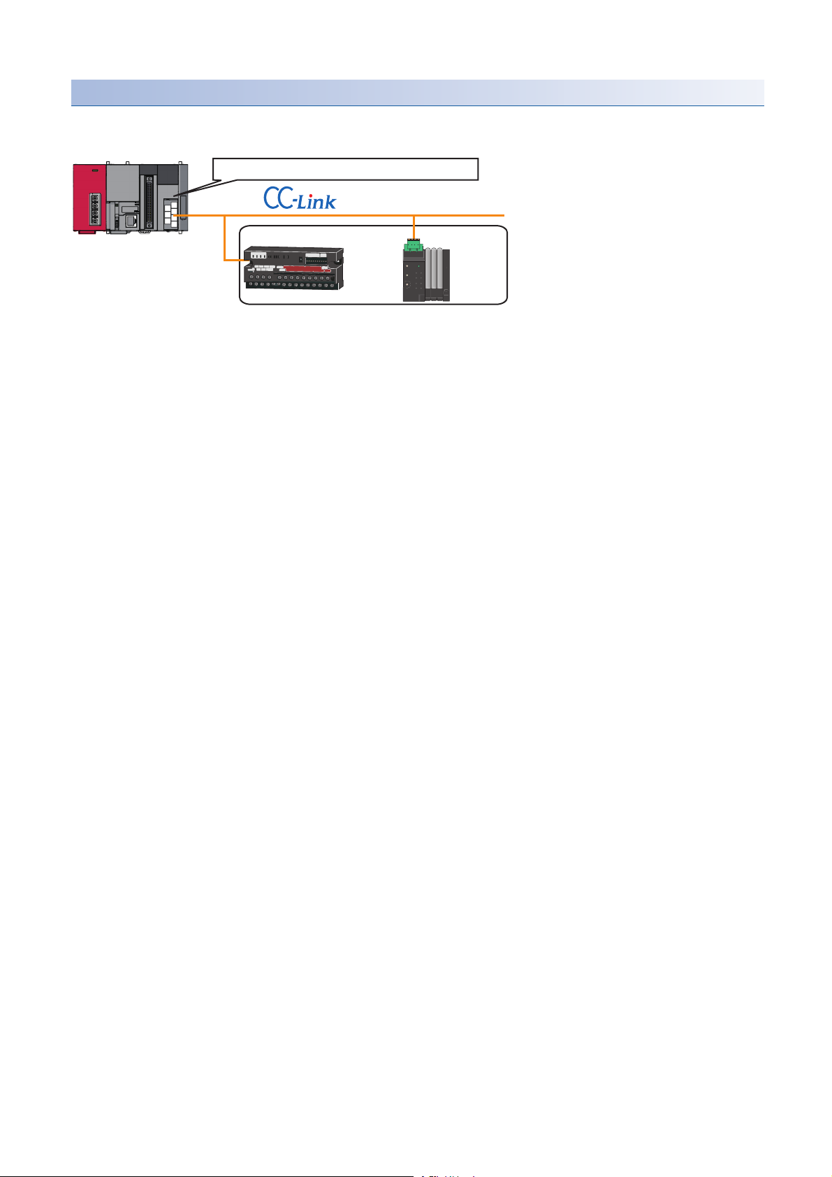
Example of a data backup
CC-Link master/local module start I/O number 10
Station No. 1 Station No. 2
Backup target
■Example of a system configuration
The following shows the example of a system configuration for data backup.
• Target module type: CC-Link
• Execution unit: Module
• Folder number setting: 15
• Target device (target module): Start I/O No.10
• Operation setting on error: Stop
78
4 CC-Link
4.5 Backing up/Restoring Data of Devices Supporting iQSS
Page 81

■Devices used in the program
Device Description Value
M0 Initialization trigger
M1000 Backup execution trigger
M1100 Backup right-to-use request trigger
M1200 Backup right-to-use confirmation trigger
M1300 Backup setting/start trigger
M2000 Backup execution cancellation trigger
M3000 Backup execution normal completion display
M3500 Backup execution abnormal completion display
M3550 Backup right-to-use acquisition failure
D1000 Right-to-use number storage area
D5000 Backup number of normally completed devices
D5001 Backup number of devices completed with an error
D5002 Backup error cause in a module
D5003 Backup error cause in a device
SM1435 Backup execution enabled
SM1436 Backup request
SM1442 Backup cancellation request
SD1435 Backup use request 1030H
SD1436 Backup right-to-use acquisition status
SD1437 Backup target module/execution unit setting Lower 8 bits: 2H
Upper 8 bits: 1H
SD1438 Backup folder number setting 15
SD1439 Backup target setting (target module) 1H
SD1444 Operation setting when a data backup error occurs 1H
SD1446 Backup execution status
SD1448 Backup number of normally completed devices
SD1449 Backup number of devices completed with an error
SD1452 Backup error cause in a module
SD1453 Backup error cause in a device
SW80.0 Station No.1 data link status
SW80.1 Station No.2 data link status
SW160.0 Station No.1 remote register use prohibited status
SW160.1 Station No.2 remote register use prohibited status
X10 Module error
X11 Host station data link status
X1F Module READY
4
For details on special relays (SM) and special registers (SD) to be used and their setting ranges, refer to the
following section.
Page 355 Special Relay (SM)/Special Register (SD) List
4 CC-Link
4.5 Backing up/Restoring Data of Devices Supporting iQSS
79
Page 82

0
M0
FMOV K0 D5000 K4
RST M3000
RST M3500
SET M1000
8
M1000
X10 X11 X1F SW80.0 SW80.1 SW160.0 SW160.1
SET M1100
17
M1100
= H0 SD1436 MOV H1030 D1000
MOV D1000 SD1435
SET M1200
26
M1200
= D1000 SD1436 SET M1300
<> D1000 SD1436 <> H0 SD1436 SET M3550
40
M1300
MOV H102 SD1437
MOV K15 SD1438
MOV H1 SD1439
MOV H1 SD1444
SET SM1436
50 = H3 SD1446 SET M3000
MOV SD1448 D5000
56 = H0FF SD1446 SET M3500
MOV SD1449 D5001
MOV SD1452 D5002
MOV SD1453 D5003
66
M3000
SET SM1435
M3500
RST M0
RST M1000
RST M1100
RST M1200
RST M1300
74
M2000
= H1 SD1446 SET SM1442
= H2 SD1446
83 END
■Sample program
4 CC-Link
80
4.5 Backing up/Restoring Data of Devices Supporting iQSS
Page 83

[Initialization]
(0) Initialize the execution result.
Initialize the normal completion display.
Initialize the abnormal completion display.
Set the backup execution trigger.
[Executing data backup/Checking data link status]
Check that the other station data link status (SW0080 to SW0083) indicates that a data link is in process before making a data backup request.
(8) Set the backup right-to-use request trigger.
[Requesting backup right to use]
(17) Store the right-to-use number.
Set the backup right-to-use request trigger.
Set the backup right-to-use confirmation trigger.
[Checking backup right to use]
(26) Set the backup setting/start trigger.
Display the right-to-use acquisition failure.
[Setting/Starting data backup]
(40) Set the target module/execution unit.
Set the target folder number.
Set the target module.
Set the operation setting when a data backup error occurs.
Set the backup request.
[Checking data backup execution]
(50) Display the normal completion.
Save the number of normally completed devices.
(56) Display the abnormal completion.
Save the number of devices completed with an error.
Save the error code (module error).
Save the error code (device error).
[Enabling the next data backup process]
(66) Enable the data backup execution.
Clear the initialization trigger.
Clear the backup execution trigger.
Clear the backup right-to-use request trigger.
Clear the backup right-to-use confirmation trigger.
Clear the backup setting/start trigger.
[Setting for cancelling the process]
(74) Set the backup cancellation request.
4
4 CC-Link
4.5 Backing up/Restoring Data of Devices Supporting iQSS
81
Page 84
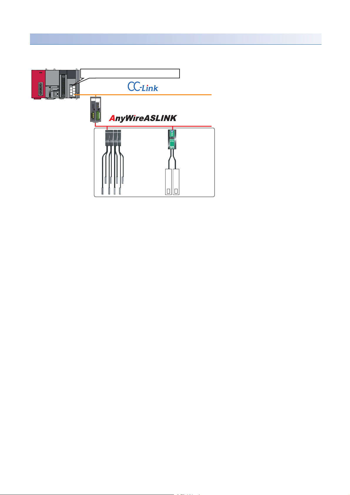
Example of a data backup (bridge module (NZ2AW1C2AL))
CC-Link master/local module start I/O number 10
Station No. 1
CC-Link-AnyWireASLINK bridge module
Address 1 to 4
ID513 (201H) to
ID516 (204H)
(Station sub-ID
513 to 516)
Address 5
ID517(205H)
(Station sub-ID 517)
Backup target
■Example of a system configuration
The following shows the example of a system configuration for data backup.
• Target module type: CC-Link
• Execution unit: Station
• Folder number setting: 18
• Target device (target module): Start I/O No.10
• Target device (station number): Station No. 1
• Operation setting on error: Stop
82
4 CC-Link
4.5 Backing up/Restoring Data of Devices Supporting iQSS
Page 85

■Devices used in the program
Device Description Value
M0 Initialization trigger
M1000 Backup execution trigger
M1100 Backup right-to-use request trigger
M1200 Backup right-to-use confirmation trigger
M1300 Backup setting/start trigger
M2000 Backup execution cancellation trigger
M3000 Backup execution normal completion display
M3500 Backup execution abnormal completion display
M3550 Backup right-to-use acquisition failure
D1000 Right-to-use number storage area
*1
D2000.1
*1
D2000.3
*1
D2000.4
*1
D2001.0
*1
D2001.1
*1
D2001.2
*1
D2001.4
*1
D2013.B
D5000 Backup number of normally completed devices
D5001 Backup number of devices completed with an error
D5002 Backup error cause in a module
D5003 Backup error cause in a device
SM1435 Backup execution enabled
SM1436 Backup request
SM1442 Backup cancellation request
SD1435 Backup use request 1090H
SD1436 Backup right-to-use acquisition status
SD1437 Backup target module/execution unit setting Lower 8 bits: 2H
SD1438 Backup folder number setting 18
SD1439 Backup target setting (target module) 1H
SD1440 Backup target setting (target device 1) 1
SD1444 Operation setting when a data backup error occurs 1H
SD1446 Backup execution status
SD1448 Backup number of normally completed devices
SD1449 Backup number of devices completed with an error
SD1452 Backup error cause in a module
SD1453 Backup error cause in a device
SW80.0 Station No.1 data link status
SW160.0 Station No.1 remote register use prohibited status
X10 Module error
X11 Host station data link status
X1F Module READY
DP/DN short error
Transmission cable voltage drop error
DP/DN disconnection error
Slave module alarm signal
Parameter access completion flag
Parameter access error
Automatic address detection flag
Remote READY
Upper 8 bits: 2H
4
*1 A device used when the remote input (RX) is set to D2000.
For details on special relays (SM) and special registers (SD) to be used and their setting ranges, refer to the
following section.
Page 355 Special Relay (SM)/Special Register (SD) List
4 CC-Link
4.5 Backing up/Restoring Data of Devices Supporting iQSS
83
Page 86
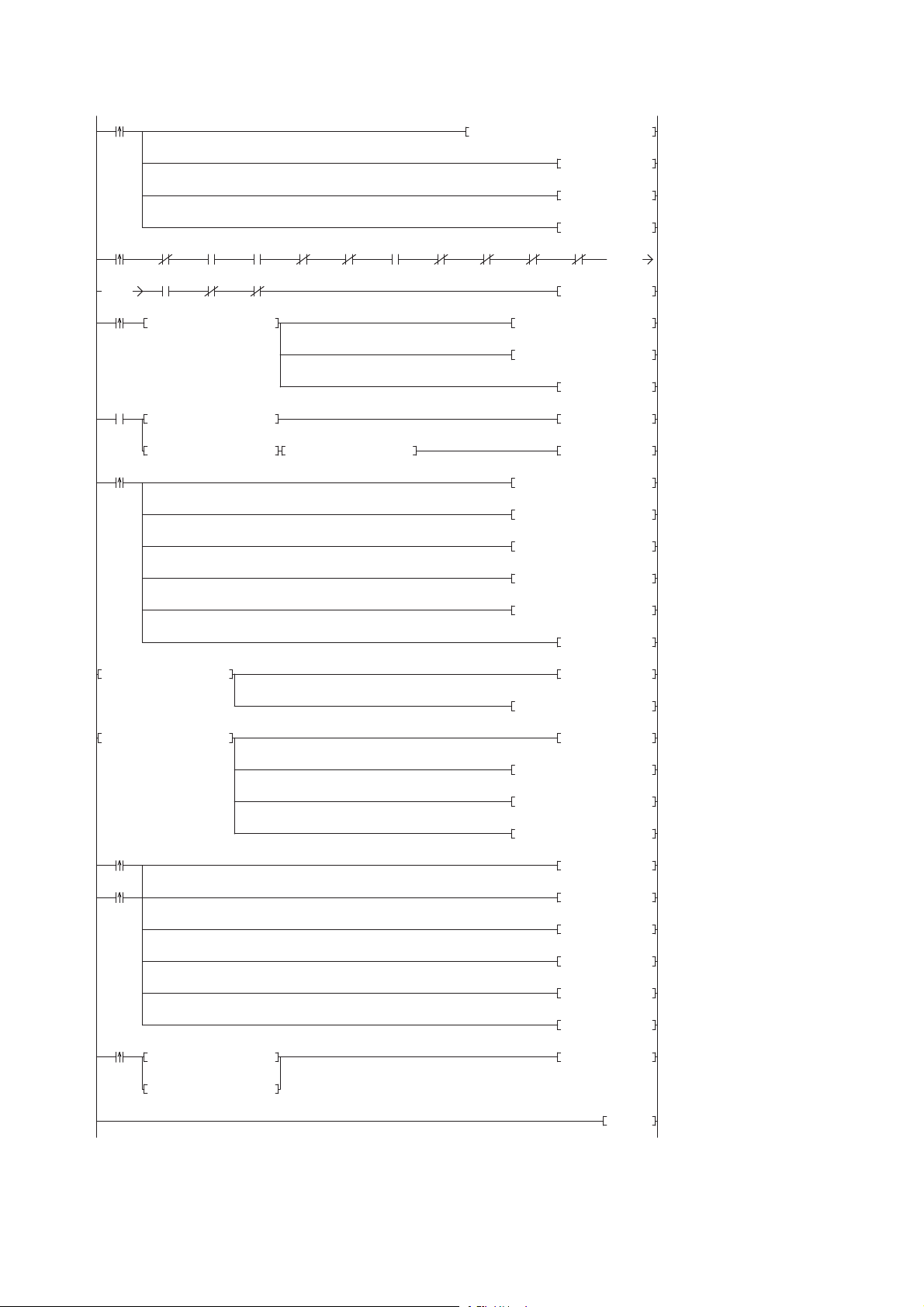
0
M0
FMOV K0 D5000 K4
RST M3000
RST M3500
SET M1000
8
M1000
X10 X11 X1F SW80.0 SW160.0D2013.B D2000.1 D2000.3 D2000.4 D2001.0
K0
K0
D2001.1 D2001.2 D2001.4
SET M1100
23
M1100
= H0 SD1436 MOV H1090 D1000
MOV D1000 SD1435
SET M1200
32
M1200
= D1000 SD1436 SET M1300
<> D1000 SD1436 <> H0 SD1436 SET M3550
46
M1300
MOV H202 SD1437
MOV K18 SD1438
MOV H1 SD1439
MOV K1 SD1440
MOV H1 SD1444
SET SM1436
58 = H3 SD1446 SET M3000
MOV SD1448 D5000
64 = H0FF SD1446 SET M3500
MOV SD1449 D5001
MOV SD1452 D5002
MOV SD1453 D5003
74
M3000
SET SM1435
M3500
RST M0
RST M1000
RST M1100
RST M1200
RST M1300
82
M2000
= H1 SD1446 SET SM1442
= H2 SD1446
91
END
■Sample program
4 CC-Link
84
4.5 Backing up/Restoring Data of Devices Supporting iQSS
Page 87

[Initialization]
(0) Initialize the execution result.
Initialize the normal completion display.
Initialize the abnormal completion display.
Set the backup execution trigger.
[Executing data backup/Checking data link status]
Check that the other station data link status (SW0080 to SW0083) indicates that a data link is in process before making a data backup request.
(8) Set the backup right-to-use request trigger.
[Requesting backup right to use]
(23) Store the right-to-use number.
Set the backup right-to-use request trigger.
Set the backup right-to-use confirmation trigger.
[Checking backup right to use]
(32) Set the backup setting/start trigger.
Display the right-to-use acquisition failure.
[Setting/Starting data backup]
(46) Set the target module/execution unit.
Set the target folder number.
Set the target module.
Set the target device 1.
Set the operation setting when a data backup error occurs.
Set the backup request.
[Checking data backup execution]
(58) Display the normal completion.
Save the number of normally completed devices.
(64) Display the abnormal completion.
Save the number of devices completed with an error.
Save the error code (module error).
Save the error code (device error).
[Enabling the next data backup process]
(74) Enable the data backup execution.
Clear the initialization trigger.
Clear the backup execution trigger.
Clear the backup right-to-use request trigger.
Clear the backup right-to-use confirmation trigger.
Clear the backup setting/start trigger.
[Setting for cancelling the process]
(82) Set the backup cancellation request.
4
4 CC-Link
4.5 Backing up/Restoring Data of Devices Supporting iQSS
85
Page 88
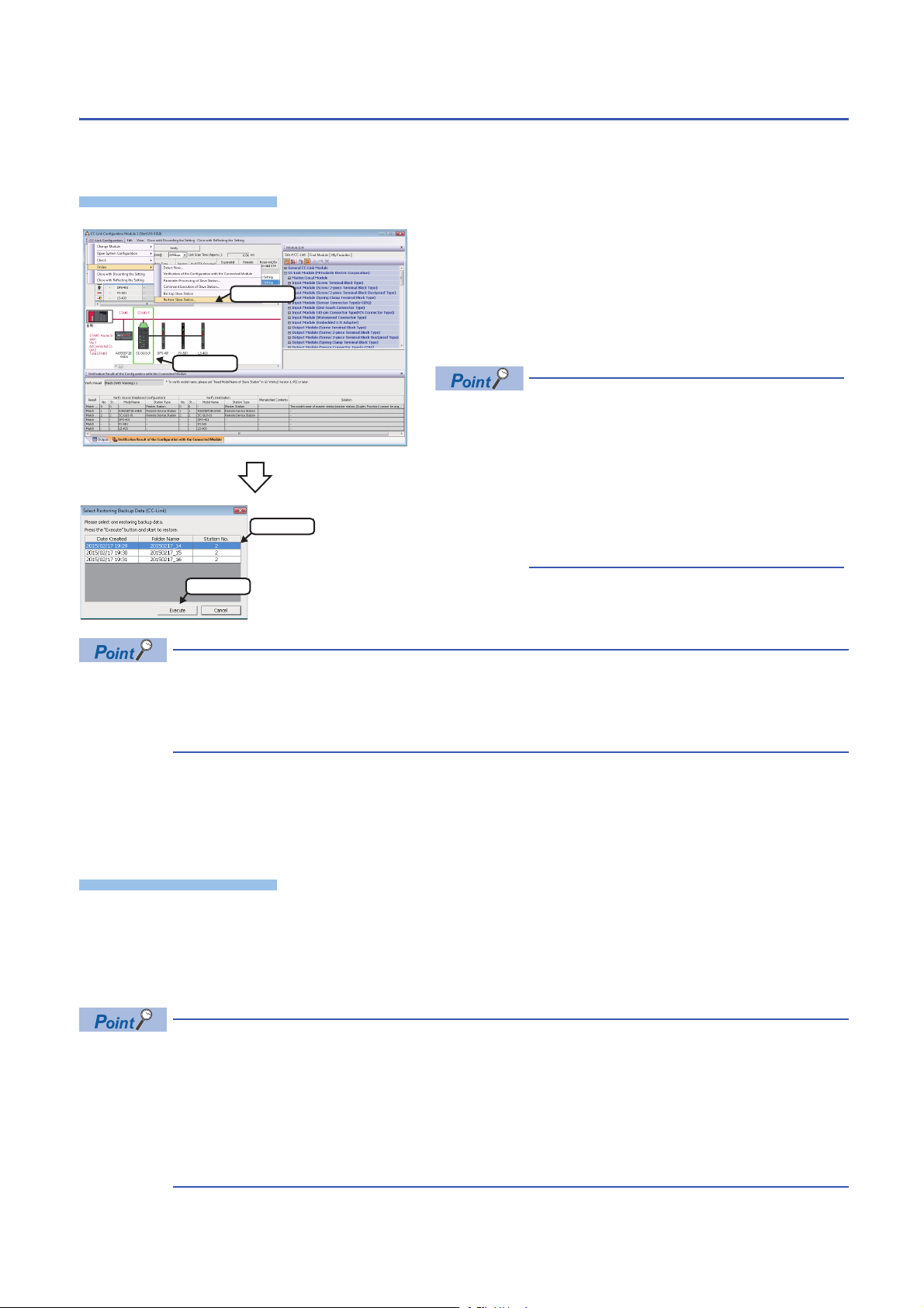
Data restoration
Operating procedure
Operating procedure
2. Select
1. Select
1. Select
2. Click
Information saved in an SD memory card can be restored to a device supporting iQSS for each station by using an
engineering tool.
1. Select a target device supporting iQSS in 'List of stations' or
'Device map area' in the "CC-Link Configuration" window, and
select [CC-Link Configuration] [Online] [Restore Slave
Station].
2. Select backup data to be restored, and click the [Execute]
button.
A list of the backup folder names (date_number) is
displayed in the column of "Folder Name".
Backup data is stored in backup folders for each
folder name (Start I/O number_Station number) in
an SD memory card.
For details on the backup folder configuration,
refer to the following section.
Page 69 Backup folder configuration
3. Read the message, and click the [OK] button.
Data is restored.
The initial value of the restoration setting (SD1444) is as follows:
• Lower 8 bits of SD1444 (operation setting on error): 0H (continue)
Use a program when restoring data with the settings other than above. (Page 87 Program execution for
data restoration)
■Data restoration method for a device supporting iQSS, which is connected to a bridge module
(NZ2AW1C2AL)
Data can be restored for a device supporting iQSS, which is connected to a bridge module (NZ2AW1C2AL), by the following
method.
1. Select a bridge module (NZ2AW1C2AL) in 'List of stations' or 'Device map area' in the "CC-Link Configuration" window.
2. Select [CC-Link Configuration] [Open System Configuration] [Open AnyWireASLINK Configuration].
3. Select [AnyWireASLINK Configuration] [Online] [Restore Slave Module] in the "AnyWireASLINK Configuration"
window.
When restoring data for a device supporting iQSS, which is connected to a bridge module (NZ2AW1C2AL), a
list of the backup data name (date_number) stored in the backup folder of CC-Link is displayed in the "Folder
Name" on the "Select Restoring Backup Data (AnyWireASLINK)" screen.
Backup data is stored in backup folders for each folder name (Station number/Station sub-ID number) in an
SD memory card.
For details on the backup folder configuration, refer to the following section.
Page 69 Backup folder configuration
86
4 CC-Link
4.5 Backing up/Restoring Data of Devices Supporting iQSS
Page 89
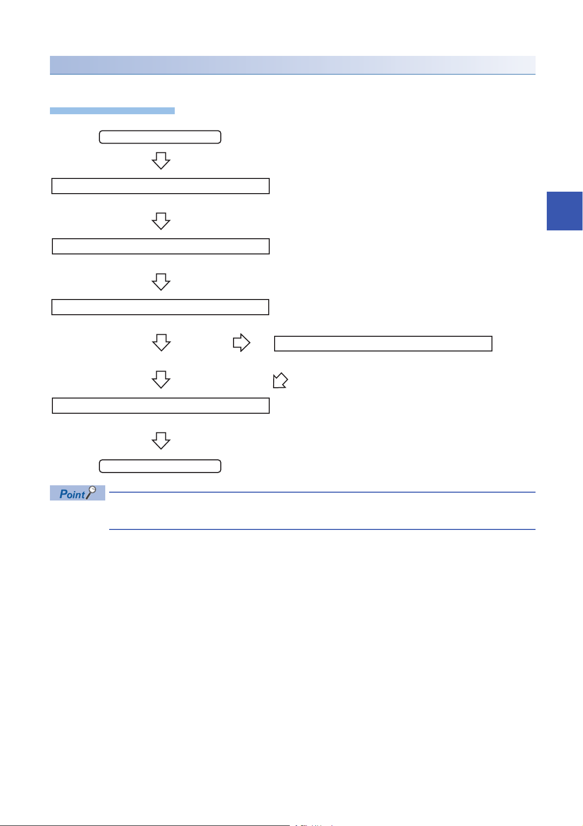
Program execution for data restoration
Operating procedure
Start
Acquiretherighttousespecialrelays/registers.
Completionofright-to-useacquisition
Setthesettingsfordatarestoration.
Requestadatarestoration
Executionofdatarestoration
Normalcompletionofrestorationprocess
Restorationerror
Enablethenextrestorationprocess.
Complete
The information saved in an SD memory card can be restored to a device supporting iQSS with a program.
Page 88 Acquiring a right to use
Page 88 Setting the restoration setting
Page 89 Performing a data restoration
Requestacancellationofrestorationprocess.
Page 89 Requiring a data restoration cancellation
4
Page 89 Releasing the right to use
For details on special relays (SM) and special registers (SD), refer to the following section.
Page 355 Special Relay (SM)/Special Register (SD) List
Cancellationofrestorationprocess
4 CC-Link
4.5 Backing up/Restoring Data of Devices Supporting iQSS
87
Page 90

Execution method of data restoration
The target device for data restoration can be set with a program.
■Acquiring a right to use
Set a value within the range from 1000H to 1FFFH to SD1435.
Right to use for data backup
• Special relays (SM) and special registers (SD) are used for data restoration.
• To prevent the same special relay (SM) and special register (SD) from being set at the same time, acquiring
a right to use of them for data backup is required.
• To acquire a right to use, specify a value which is not duplicate with values for other request sources to
SD1435, and check that the value set to SD1435 is stored to SD1436.
• Normal operation cannot be assured if the data backup function is performed without confirming the
acquisition of a right to use.
■Setting the restoration setting
1. Setting a target module type
Set the target module type for data restoration to the lower 8 bits of SD1437.
Target module type Description
2H: CC-Link Set the target module type.
2. Setting an execution unit
Set the unit of execution for data restoration to the upper 8 bits of SD1437.
Execution unit Description
1H: Module unit Set this to specify all devices supporting iQSS which are connected to the CC-Link master/local module with the
2H: Station unit Set this to specify either of the following devices supporting iQSS which are connected to the CC-Link master/local
3H: Station sub-ID unit Set this to specify the device supporting iQSS with the specified station sub-ID number which is connected to the
specified start I/O number.
module with the specified start I/O number: device supporting iQSS with the specified station number or all devices
supporting iQSS which are connected to the module with the specified station number.
module with the specified station number among the devices supporting iQSS which are connected to the CC-Link IE
Field Network master/local module with the specified start I/O number.
3. Selecting a folder for data restoration
Set the number for backup folder name, from which data is to be restored, to SD1438.
Target folder Description
00 to 99: Target folder specification Specify the number among the numbers for backup folder name, 00 to 99.
88
4 CC-Link
4.5 Backing up/Restoring Data of Devices Supporting iQSS
Page 91

4. Setting a target device
• Setting a module
When '1H' (module unit) is set for the execution unit in the step of 'Setting the execution unit', set the start I/O number of a
target device for data restoration to SD1439.
Target device (Module) Description
0 to FFH: Start I/O number When '1H' (module unit) is set for the execution unit, set the value obtained by dividing the start I/O number of a CC-
Link master/local module, which is connected to a target device supporting iQSS, by 16.
• Setting a station number
When '2H' (station unit) or '3H' (station sub-ID unit) is set for the execution unit in the step of 'Setting the execution unit', set
the station number of a target device for data restoration to SD1440.
Target device (Station
number)
1 to 64: Station number When '2H' (station unit) or '3H' (station sub-ID unit) is set for the execution unit, set the station number of a target
• Setting a station sub-ID number
When '3H' (station sub-ID unit) is set for the execution unit in the step of 'Setting the execution unit', set the station sub-ID
number of a target device for data restoration to SD1441.
Target device (Station sub-ID
number)
0 to 9999: Station sub-ID number When '3H' (station sub-ID unit) is set for the execution unit, set the station sub-ID number of a target device supporting
Description
device supporting iQSS or a device supporting iQSS which is connected to the module with the specified station
number.
Description
iQSS.
4
To restore the data of a device supporting iQSS which is connected to a bridge module (NZ2AW1C2AL), set
the ID number of AnyWireASLINK to SD1441.
For details on the ID number (SD1440) of AnyWireASLINK, refer to the following section.
Page 47 Setting the restoration setting
5. Setting the operation setting when a data restoration error occurs
Set the operation on error to the lower 8 bits of SD1444 in order to in order to restore data for multiple devices supporting
iQSS.
Operation on error Description
0H: Continue Set this to continue a data restoration even if it fails on some devices while being performed to multiple devices
supporting iQSS.
1H: Stop Set this to stop a data restoration even if it fails on some devices while being performed to multiple devices supporting
iQSS.
■Performing a data restoration
Data is restored if SM1439 is turned ON while SD1446 is '1H' (ready).
Once data is restored, SD1446 will be '2H' (being executed).
Check that the other station data link status (SW0080 to SW0083) indicates that a data link is in process before performing a
data restoration.
■Requiring a data restoration cancellation
The data restoration stops if SM1442 is turned ON while SD1446 is '1H' (ready) or '2H' (being executed).
■Releasing the right to use
When SM1435 is turned ON after a data restoration is completed (including a cancellation or an error), the right to use is
released and the next data restoration is ready to be performed.
SM1435 turns ON to OFF when the right to use is released.
If the right to use is released even though it has already been done, SM1435 remains ON since no processing is performed.
In that case, set SM1435 to OFF.
4 CC-Link
4.5 Backing up/Restoring Data of Devices Supporting iQSS
89
Page 92

Example of a data restoration
CC-Link master/local module start I/O number 10
Station No. 1 Station No. 2
Restoration target
■Example of a system configuration
The following shows the example of a system configuration for data restoration.
• Target module type: CC-Link
• Execution unit: Station
• Folder number setting: 15
• Target device (target module): Start I/O No.10
• Target device (station number): Station No. 1
• Operation setting on error: Stop
90
4 CC-Link
4.5 Backing up/Restoring Data of Devices Supporting iQSS
Page 93

■Devices used in the program
Device Description Value
M0 Initialization trigger
M1000 Restoration execution trigger
M1100 Restoration right-to-use request trigger
M1200 Restoration right-to-use confirmation trigger
M1300 Restoration setting/start trigger
M2000 Restoration execution cancellation trigger
M3000 Restoration execution normal completion display
M3500 Restoration execution abnormal completion display
M3550 Restoration right-to-use acquisition failure
D1000 Right-to-use number storage area
D5000 Restoration number of normally completed devices
D5001 Restoration number of devices completed with an error
D5002 Restoration error cause in a module
D5003 Restoration error cause in a device
SM1435 Restoration execution enabled
SM1439 Restoration request
SM1442 Restoration cancellation request
SD1435 Restoration use request 1040H
SD1436 Restoration right-to-use acquisition status
SD1437 Restoration target module/execution unit setting Lower 8 bits: 2H
Upper 8 bits: 2H
SD1438 Restoration folder number setting 15
SD1439 Restoration target setting (target module) 1H
SD1440 Restoration target setting (target device 1) 1
SD1444 Operation setting when a data restoration error occurs 1H
SD1446 Restoration execution status
SD1448 Restoration number of normally completed devices
SD1449 Restoration number of devices completed with an error
SD1452 Restoration error cause in a module
SD1453 Restoration error cause in a device
SW80.0 Station No.1 data link status
SW160.0 Station No.1 remote register use prohibited status
X10 Module error
X11 Host station data link status
X1F Module READY
4
For details on special relays (SM) and special registers (SD) to be used and their setting ranges, refer to the
following section.
Page 355 Special Relay (SM)/Special Register (SD) List
4 CC-Link
4.5 Backing up/Restoring Data of Devices Supporting iQSS
91
Page 94
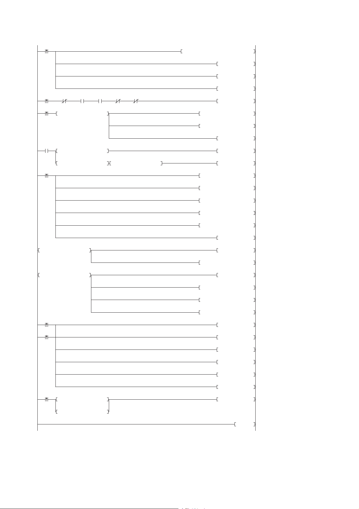
0
M0
FMOV K0 D5000 K4
RST M3000
RST M3500
SET M1000
8
M1000
X10 X11 X1F SW80.0 SW160.0
SET M1100
15
M1100
= H0 SD1436 MOV H1040 D1000
MOV D1000 SD1435
SET M1200
24
M1200
= D1000 SD1436 SET M1300
<> D1000 SD1436 <> H0 SD1436 SET M3550
38
M1300
MOV H202 SD1437
MOV K15 SD1438
MOV H1 SD1439
MOV K1 SD1440
MOV H1 SD1444
SET SM1439
50 = H3 SD1446 SET M3000
MOV SD1448 D5000
56 = H0FF SD1446 SET M3500
MOV SD1449 D5001
MOV SD1452 D5002
MOV SD1453 D5003
66
M3000
SET SM1435
M3500
RST M0
RST M1000
RST M1100
RST M1200
RST M1300
74
M2000
= H1 SD1446 SET SM1442
= H2 SD1446
83 END
■Sample program
4 CC-Link
92
4.5 Backing up/Restoring Data of Devices Supporting iQSS
Page 95

[Initialization]
(0) Initialize the execution result.
Initialize the normal completion display.
Initialize the abnormal completion display.
Set the restoration execution trigger.
[Executing data restoration/Checking data link status]
Check that the other station data link status (SW0080 to SW0083) indicates that a data link is in process before making a data restoration request.
(8) Set the restoration right-to-use request trigger.
[Requesting restoration right to use]
(15) Store the right-to-use number.
Set the restoration right-to-use request trigger.
Set the restoration right-to-use confirmation trigger.
[Checking restoration right to use]
(24) Set the restoration setting/start trigger.
Display the right-to-use acquisition failure.
[Setting/Starting data restoration]
(38) Set the target module/execution unit.
Set the target folder number.
Set the target module.
Set the target device 1.
Set the operation setting when a data restoration error occurs.
Set the restoration request.
[Checking data restoration execution]
(50) Display the normal completion.
Save the number of normally completed devices.
(56) Display the abnormal completion.
Save the number of devices completed with an error.
Save the error code (module error).
Save the error code (device error).
[Enabling the next data restoration process]
(66) Enable the data restoration execution.
Clear the initialization trigger.
Clear the restoration execution trigger.
Clear the restoration right-to-use request trigger.
Clear the restoration right-to-use confirmation trigger.
Clear the restoration setting/start trigger.
[Setting for cancelling the process]
(74) Set the restoration cancellation request.
4
4 CC-Link
4.5 Backing up/Restoring Data of Devices Supporting iQSS
93
Page 96
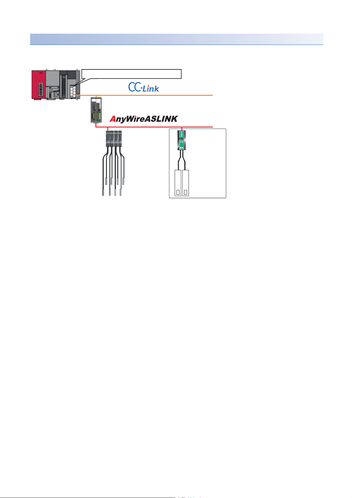
Example of a data restoration (bridge module (NZ2AW1C2AL))
CC-Link master/local module start I/O number 10
Station No. 1
CC-Link-AnyWireASLINK bridge module
Address 1 to 4
ID513 (201H) to
ID516 (204H)
(Station sub-ID
513 to 516)
Address 5
ID517(205H)
(Station sub-ID 517)
Restoration target
■Example of a system configuration
The following shows the example of a system configuration for data restoration.
• Target module type: CC-Link
• Execution unit: Station sub-ID
• Folder number setting: 18
• Target device (target module): Start I/O No.10
• Target device (station number): Station No. 1
• Target device (station sub-ID number): Station sub-ID 517
• Operation setting on error: Stop
94
4 CC-Link
4.5 Backing up/Restoring Data of Devices Supporting iQSS
Page 97

■Devices used in the program
Device Description Value
M0 Initialization trigger
M1000 Restoration execution trigger
M1100 Restoration right-to-use request trigger
M1200 Restoration right-to-use confirmation trigger
M1300 Restoration setting/start trigger
M2000 Restoration execution cancellation trigger
M3000 Restoration execution normal completion display
M3500 Restoration execution abnormal completion display
M3550 Restoration right-to-use acquisition failure
D1000 Right-to-use number storage area
*1
D2000.1
*1
D2000.3
*1
D2000.4
*1
D2001.0
*1
D2001.1
*1
D2001.2
*1
D2001.4
*1
D2013.B
D5000 Restoration number of normally completed devices
D5001 Restoration number of devices completed with an error
D5002 Restoration error cause in a module
D5003 Restoration error cause in a device
SM1435 Restoration execution enabled
SM1439 Restoration request
SM1442 Restoration cancellation request
SD1435 Restoration use request 10A0H
SD1436 Restoration right-to-use acquisition status
SD1437 Restoration target module/execution unit setting Lower 8 bits: 2H
SD1438 Restoration folder number setting 18
SD1439 Restoration target setting (target module) 1H
SD1440 Restoration target setting (target device 1) 1
SD1441 Restoration target setting (target device 2) 517
SD1444 Operation setting when a data restoration error occurs 1H
SD1446 Restoration execution status
SD1448 Restoration number of normally completed devices
SD1449 Restoration number of devices completed with an error
SD1452 Restoration error cause in a module
SD1453 Restoration error cause in a device
SW80.0 Station No.1 data link status
SW160.0 Station No.1 remote register use prohibited status
X10 Module error
X11 Host station data link status
X1F Module READY
DP/DN short error
Transmission cable voltage drop error
DP/DN disconnection error
Slave module alarm signal
Parameter access completion flag
Parameter access error
Automatic address detection flag
Remote READY
Upper 8 bits: 3H
4
*1 A device used when the remote input (RX) is set to D2000.
For details on special relays (SM) and special registers (SD) to be used and their setting ranges, refer to the
following section.
Page 355 Special Relay (SM)/Special Register (SD) List
4 CC-Link
4.5 Backing up/Restoring Data of Devices Supporting iQSS
95
Page 98

■Sample program
0
M0
FMOV K0 D5000 K4
RST M3000
RST M3500
SET M1000
8
M1000 X10 X11 X1F SW80.0 SW160.0D2013.B D2000.1 D2000.3 D2000.4 D2001.0
K0
K0
D2001.1 D2001.2 D2001.4
SET M1100
23
M1000
= H0 SD1436 MOV H10A0 D1000
MOV D1000 SD1435
SET M1200
32
M1200
= D1000 SD1436 SET M1300
<> D1000 SD1436 <> H0 SD1436 SET M3550
46
M1300
MOV H302 SD1437
MOV K18 SD1438
MOV H1 SD1439
MOV K1 SD1440
MOV K517 SD1441
MOV H1 SD1444
SET SM1439
60 = H3 SD1446 SET M3000
MOV SD1448 D5000
66 = H0FF SD1446 SET M3500
MOV SD1449 D5001
MOV SD1452 D5002
MOV SD1453 D5003
76
M3000
SET SM1435
M3500
RST M0
RST M1000
RST M1100
RST M1200
RST M1300
84
M2000
= H1 SD1446 SET SM1442
= H2 SD1446
93 END
4 CC-Link
96
4.5 Backing up/Restoring Data of Devices Supporting iQSS
Page 99

[Initialization]
(0) Initialize the execution result.
Initialize the normal completion display.
Initialize the abnormal completion display.
Set the restoration execution trigger.
[Executing data restoration/Checking data link status]
Check that the other station data link status (SW0080 to SW0083) indicates that a data link is in process before making a data restoration request.
(8) Set the restoration right-to-use request trigger.
[Requesting restoration right to use]
(23) Store the right-to-use number.
Set the restoration right-to-use request trigger.
Set the restoration right-to-use confirmation trigger.
[Checking restoration right to use]
(32) Set the restoration setting/start trigger.
Display the right-to-use acquisition failure.
[Setting/Starting data restoration]
(46) Set the target module/execution unit.
Set the target folder number.
Set the target module.
Set the target device.
Set the operation setting when a data restoration error occurs.
Set the restoration request.
[Checking data restoration execution]
(60) Display the normal completion.
Save the number of normally completed devices.
(66) Display the abnormal completion.
Save the number of devices completed with an error.
Save the error code (module error).
Save the error code (device error).
[Enabling the next data restoration process]
(76) Enable the data restoration execution.
Clear the initialization trigger.
Clear the restoration execution trigger.
Clear the restoration right-to-use request trigger.
Clear the restoration right-to-use confirmation trigger.
Clear the restoration setting/start trigger.
[Setting for cancelling the process]
(84) Set the restoration cancellation request.
4
4 CC-Link
4.5 Backing up/Restoring Data of Devices Supporting iQSS
97
Page 100
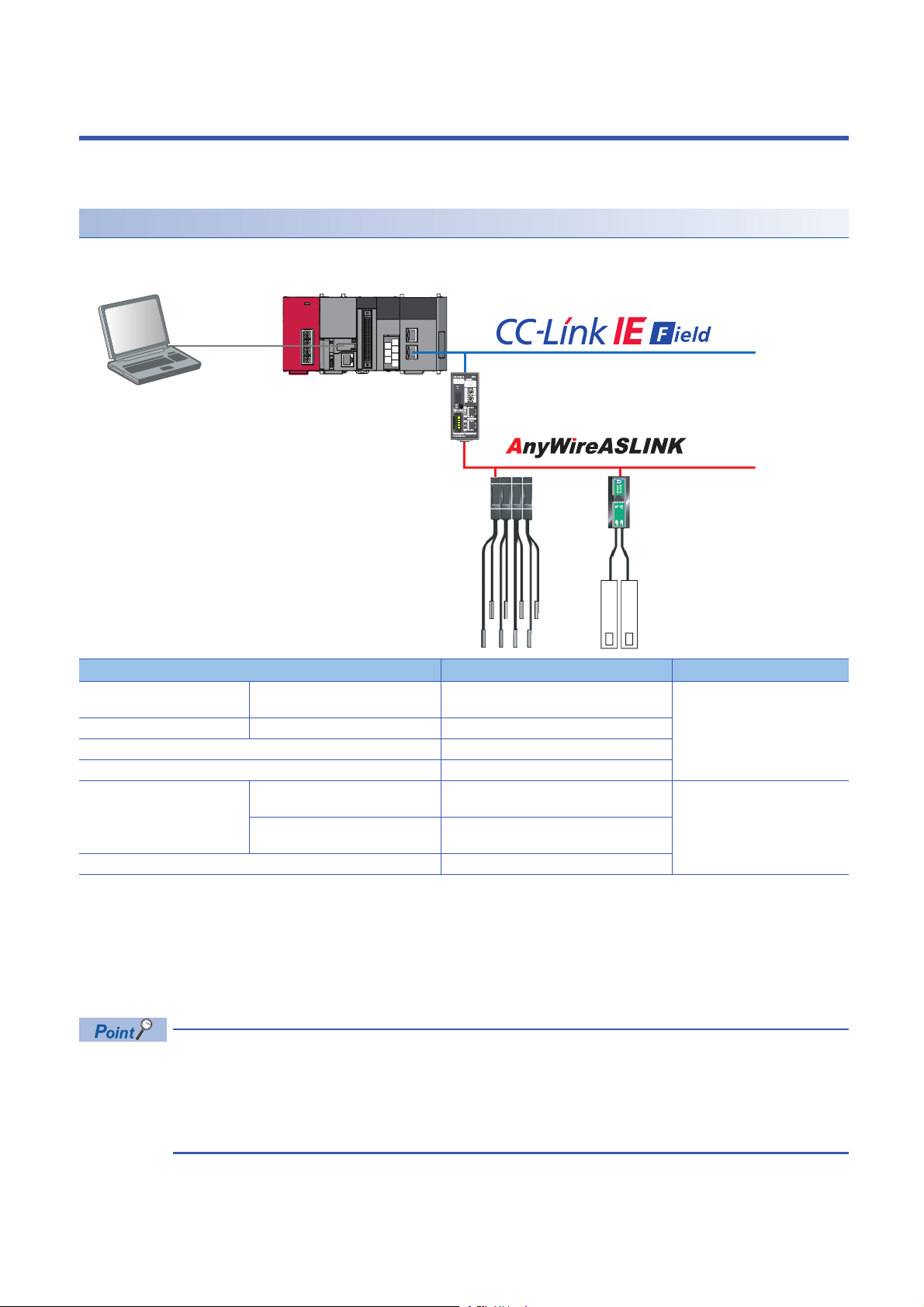
5 CC-Link IE Field Network
24V
0V
DP
DN
LG
Engineering tool CPU module CC-Link IE Field Network master/local module
CC-Link IE Field Network-AnyWireASLINK bridge module
ASLINKER (Input)ASLINKAMP (Input)
This chapter explains the operation methods when using iQ Sensor Solution functions for MELSEC-L series or Q series via
CC-Link IE Field Network.
System configuration
This section explains the iQ Sensor Solution functions for CC-Link IE Field Network using the following system configuration.
Type Model name Manufacturer
Engineering tool GX Works2 SWnDND-GXW2 and SWnDNC-GXW2 ('n'
indicates its version.)
CPU module LCPU L26CPU-BT
CC-Link IE Field Network master/local module LJ71GF11-T2
CC-Link IE Field Network-AnyWireASLINK bridge module NZ2AW1GFAL
ASLINKAMP (Input) Photoelectric sensor B289SB-01AP-CAM20 (ASLINKAMP master)
B289SB-01AP-CAS (ASLINKAMP slave)
Fiber sensor B289SB-01AF-CAS (ASLINKAMP slave)
ASLINKER (Input) B281SB-02U-CC20
B289SB-01AF-CAS (ASLINKAMP slave)
For details on the devices supporting iQSS and the iQ Sensor Solution functions available for CC-Link IE Field Network, refer
to the following section.
Page 325 Devices that Support iQ Sensor Solution
For information on the engineering tools available for iQ Sensor Solution and the versions of engineering tools supporting
each iQ Sensor Solution function, refer to the following section.
Page 337 Engineering Tool and Version List
• Before using each iQ Sensor Solution function, complete the installation and wiring of the actual system
configuration, and set network parameters and other settings required for communication with a device
supporting iQSS.
• When a CC-Link IE Field Network master/local module operates as a master operating station, iQ Sensor
Solution functions are available.
Mitsubishi Electric Corporation
AnyWire Corporation
98
5 CC-Link IE Field Network
 Loading...