

Page 1

MELSEC iQ-R Simple Motion Module
User's Manual (Startup)
-RD77MS2 -RD77GF4
-RD77MS4 -RD77GF8
-RD77MS8 -RD77GF16
-RD77MS16 -RD77GF32
Page 2

Page 3
SAFETY PRECAUTIONS
WARNING
Indicates that incorrect handling may cause hazardous conditions, resulting in
death or severe injury.
CAUTION
Indicates that incorrect handling may cause hazardous conditions, resulting in
minor or moderate injury or property damage.
(Read these precautions before using this product.)
Before using this product, please read this manual and the relevant manuals carefully and pay full attention to safety to handle
the product correctly.
The precautions given in this manual are concerned with this product only. Refer to the MELSEC iQ-R Module Configuration
Manual for a description of the PLC system safety precautions.
In this manual, the safety precautions are classified into two levels: " WARNING" and " CAUTION".
Under some circumstances, failure to observe the precautions given under " CAUTION" may lead to serious
consequences.
Observe the precautions of both levels because they are important for personal and system safety.
Make sure that the end users read this manual and then keep the manual in a safe place for future reference.
[Design Precautions]
WARNING
● Configure safety circuits external to the programmable controller to ensure that the entire system
operates safely even when a fault occurs in the external power supply or the programmable controller.
Failure to do so may result in an accident due to an incorrect output or malfunction.
(1) Emergency stop circuits, protection circuits, and protective interlock circuits for conflicting
operations (such as forward/reverse rotations or upper/lower limit positioning) must be configured
external to the programmable controller.
(2) When the programmable controller detects an abnormal condition, it stops the operation and all
outputs are:
• Turned off if the overcurrent or overvoltage protection of the power supply module is activated.
• Held or turned off according to the parameter setting if the self-diagnostic function of the CPU
module detects an error such as a watchdog timer error.
(3) All outputs may be turned on if an error occurs in a part, such as an I/O control part, where the
CPU module cannot detect any error. To ensure safety operation in such a case, provide a safety
mechanism or a fail-safe circuit external to the programmable controller. For a fail-safe circuit
example, refer to "General Safety Requirements" in the MELSEC iQ-R Module Configuration
Manual.
(4) Outputs may remain on or off due to a failure of a component such as a relay and transistor in an
output circuit. Configure an external circuit for monitoring output signals that could cause a
serious accident.
● In an output circuit, when a load current exceeding the rated current or an overcurrent caused by a
load short-circuit flows for a long time, it may cause smoke and fire. To prevent this, configure an
external safety circuit, such as a fuse.
● Configure a circuit so that the programmable controller is turned on first and then the external power
supply. If the external power supply is turned on first, an accident may occur due to an incorrect output
or malfunction.
● For the operating status of each station after a communication failure, refer to manuals relevant to the
network. Incorrect output or malfunction due to a communication failure may result in an accident.
1
Page 4

[Design Precautions]
WARNING
● When connecting an external device with a CPU module or intelligent function module to modify data
of a running programmable controller, configure an interlock circuit in the program to ensure that the
entire system will always operate safely. For other forms of control (such as program modification,
parameter change, forced output, or operating status change) of a running programmable controller,
read the relevant manuals carefully and ensure that the operation is safe before proceeding. Improper
operation may damage machines or cause accidents.
● Especially, when a remote programmable controller is controlled by an external device, immediate
action cannot be taken if a problem occurs in the programmable controller due to a communication
failure. To prevent this, configure an interlock circuit in the program, and determine corrective actions
to be taken between the external device and CPU module in case of a communication failure.
● Do not write any data to the "system area" and "write-protect area" of the buffer memory in the
module. Also, do not use any "use prohibited" signals as an output signal from the CPU module to
each module. Doing so may cause malfunction of the programmable controller system. For the
"system area", "write-protect area", and the "use prohibited" signals, refer to the user's manual for the
module used.
● If a communication cable is disconnected, the network may be unstable, resulting in a communication
failure of multiple stations. Configure an interlock circuit in the program to ensure that the entire
system will always operate safely even if communications fail. Failure to do so may result in an
accident due to an incorrect output or malfunction.
● To maintain the safety of the programmable controller system against unauthorized access from
external devices via the network, take appropriate measures. To maintain the safety against
unauthorized access via the Internet, take measures such as installing a firewall.
● Configure safety circuits external to the programmable controller to ensure that the entire system
operates safely even when a fault occurs in the external power supply or the programmable controller.
Failure to do so may result in an accident due to an incorrect output or malfunction.
(1) Machine home position return is controlled by two kinds of data: a home position return direction
and a home position return speed. Deceleration starts when the proximity dog signal turns on. If
an incorrect home position return direction is set, motion control may continue without
deceleration. To prevent machine damage caused by this, configure an interlock circuit external to
the programmable controller.
(2) When the module detects an error, the motion slows down and stops or the motion rapidly stops,
depending on the stop group setting in parameter. Set the parameter to meet the specifications of
a positioning control system. In addition, set the home position return parameter and positioning
data within the specified setting range.
(3) Outputs may remain on or off, or become undefined due to a failure of a component such as an
insulation element and transistor in an output circuit, where the module cannot detect any error. In
a system that the incorrect output could cause a serious accident, configure an external circuit for
monitoring output signals.
● If safety standards (ex., robot safety rules, etc.,) apply to the system using the module, servo amplifier
and servomotor, make sure that the safety standards are satisfied.
● Construct a safety circuit externally of the module or servo amplifier if the abnormal operation of the
module or servo amplifier differs from the safety directive operation in the system.
2
Page 5
[Design Precautions]
WARNING
● Do not remove the SSCNET cable while turning on the control circuit power supply of the module
and servo amplifier. Do not see directly the light generated from SSCNET connector of the module
or servo amplifier and the end of SSCNET cable. When the light gets into eyes, you may feel
something wrong with eyes. (The light source of SSCNET complies with class1 defined in JISC6802
or IEC60825-1.)
[Design Precautions]
CAUTION
● Do not install the control lines or communication cables together with the main circuit lines or power
cables. Keep a distance of 100 mm or more between them. Failure to do so may result in malfunction
due to noise.
● During control of an inductive load such as a lamp, heater, or solenoid valve, a large current
(approximately ten times greater than normal) may flow when the output is turned from off to on.
Therefore, use a module that has a sufficient current rating.
● After the CPU module is powered on or is reset, the time taken to enter the RUN status varies
depending on the system configuration, parameter settings, and/or program size. Design circuits so
that the entire system will always operate safely, regardless of the time.
● Do not power off the programmable controller or reset the CPU module while the settings are being
written. Doing so will make the data in the flash ROM and SD memory card undefined. The values
need to be set in the buffer memory and written to the flash ROM and SD memory card again. Doing
so also may cause malfunction or failure of the module.
● When changing the operating status of the CPU module from external devices (such as the remote
RUN/STOP functions), select "Do Not Open by Program" for "Opening Method" of "Module
Parameter". If "Open by Program" is selected, an execution of the remote STOP function causes the
communication line to close. Consequently, the CPU module cannot reopen the line, and external
devices cannot execute the remote RUN function.
[Installation Precautions]
WARNING
● Shut off the external power supply (all phases) used in the system before mounting or removing the
module. Failure to do so may result in electric shock or cause the module to fail or malfunction.
3
Page 6

[Installation Precautions]
CAUTION
● Use the programmable controller in an environment that meets the general specifications in the Safety
Guidelines included with the base unit. Failure to do so may result in electric shock, fire, malfunction,
or damage to or deterioration of the product.
● To mount a module, place the concave part(s) located at the bottom onto the guide(s) of the base unit,
and push in the module until the hook(s) located at the top snaps into place. Incorrect interconnection
may cause malfunction, failure, or drop of the module.
● To mount a module with no module fixing hook, place the concave part(s) located at the bottom onto
the guide(s) of the base unit, push in the module, and fix it with screw(s). Incorrect interconnection
may cause malfunction, failure, or drop of the module.
● When using the programmable controller in an environment of frequent vibrations, fix the module with
a screw.
● Tighten the screws within the specified torque range. Undertightening can cause drop of the screw,
short circuit, or malfunction. Overtightening can damage the screw and/or module, resulting in drop,
short circuit, or malfunction.
● When using an extension cable, connect it to the extension cable connector of the base unit securely.
Check the connection for looseness. Poor contact may cause malfunction.
● When using an SD memory card, fully insert it into the SD memory card slot. Check that it is inserted
completely. Poor contact may cause malfunction.
● Securely insert an extended SRAM cassette into the cassette connector of the CPU module. After
insertion, close the cassette cover and check that the cassette is inserted completely. Poor contact
may cause malfunction.
● Do not directly touch any conductive parts and electronic components of the module, SD memory
card, extended SRAM cassette, or connector. Doing so can cause malfunction or failure of the
module.
[Wiring Precautions]
WARNING
● Shut off the external power supply (all phases) used in the system before installation and wiring.
Failure to do so may result in electric shock or cause the module to fail or malfunction.
● After installation and wiring, attach a blank cover module (RG60) to each empty slot and an included
extension connector protective cover to the unused extension cable connector before powering on the
system for operation. Failure to do so may result in electric shock.
4
Page 7

[Wiring Precautions]
CAUTION
● Individually ground the FG and LG terminals of the programmable controller with a ground resistance
of 100 ohms or less. Failure to do so may result in electric shock or malfunction.
● Use a solderless terminal with an insulation sleeve for terminal block wiring. Note that up to two
solderless terminals can be connected per terminal block.
● Use applicable solderless terminals and tighten them within the specified torque range. If any spade
solderless terminal is used, it may be disconnected when the terminal screw comes loose, resulting in
failure.
● Check the rated voltage and signal layout before wiring to the module, and connect the cables
correctly. Connecting a power supply with a different voltage rating or incorrect wiring may cause fire
or failure.
● Connectors for external devices must be crimped or pressed with the tool specified by the
manufacturer, or must be correctly soldered. Incomplete connections may cause short circuit, fire, or
malfunction.
● Securely connect the connector to the module. Poor contact may cause malfunction.
● Do not install the control lines or communication cables together with the main circuit lines or power
cables. Keep a distance of 100 mm or more between them. Failure to do so may result in malfunction
due to noise.
● When an overcurrent caused by an error of an external device or a failure of a module flows for a long
time, it may cause smoke and fire. To prevent this, configure an external safety circuit, such as a fuse.
● Place the cables in a duct or clamp them. If not, dangling cable may swing or inadvertently be pulled,
resulting in damage to the module or cables or malfunction due to poor contact. Do not clamp the
extension cables with the jacket stripped. Doing so may change the characteristics of the cables,
resulting in malfunction.
● When disconnecting the communication cable or power cable from the module, do not pull the cable
by the cable part. For the cable connected to the terminal block, loosen the terminal screws. Pulling
the cable connected to the module may result in malfunction or damage to the module or cable.
● Check the interface type and correctly connect the cable. Incorrect wiring (connecting the cable to an
incorrect interface) may cause failure of the module and external device.
● Tighten the terminal screws or connector screws within the specified torque range. Undertightening
can cause drop of the screw, short circuit, fire, or malfunction. Overtightening can damage the screw
and/or module, resulting in drop, short circuit, fire, or malfunction.
● Tighten the terminal block mounting screws, terminal screws, and module fixing screws within each
specified torque range. Undertightening of the terminal block mounting screws and terminal screws
can cause short circuit, fire, or malfunction. Overtightening of them can damage the screw and/or
module, resulting in drop, short circuit, or malfunction. Undertightening of the module fixing screws
can cause drop of the screw. Overtightening of them can damage the screw and/or module, resulting
in drop.
● When disconnecting the cable from the module, do not pull the cable by the cable part. For the cable
with connector, hold the connector part of the cable. For the cable connected to the terminal block,
loosen the terminal screw. Pulling the cable connected to the module may result in malfunction or
damage to the module or cable.
5
Page 8
[Wiring Precautions]
CAUTION
● Prevent foreign matter such as dust or wire chips from entering the module. Such foreign matter can
cause a fire, failure, or malfunction.
● A protective film is attached to the top of the module to prevent foreign matter, such as wire chips,
from entering the module during wiring. Do not remove the film during wiring. Remove it for heat
dissipation before system operation.
● Programmable controllers must be installed in control panels. Connect the main power supply to the
power supply module in the control panel through a relay terminal block. Wiring and replacement of a
power supply module must be performed by qualified maintenance personnel with knowledge of
protection against electric shock. For wiring, refer to the MELSEC iQ-R Module Configuration Manual.
● For Ethernet cables to be used in the system, select the ones that meet the specifications in this
manual. If not, normal data transmission is not guaranteed.
[Startup and Maintenance Precautions]
WARNING
● Do not touch any terminal while power is on. Doing so will cause electric shock or malfunction.
● Correctly connect the battery connector. Do not charge, disassemble, heat, short-circuit, solder, or
throw the battery into the fire. Also, do not expose it to liquid or strong shock. Doing so will cause the
battery to produce heat, explode, ignite, or leak, resulting in injury and fire.
● Shut off the external power supply (all phases) used in the system before cleaning the module or
retightening the terminal screws, connector screws, or module fixing screws. Failure to do so may
result in electric shock.
[Startup and Maintenance Precautions]
CAUTION
● When connecting an external device with a CPU module or intelligent function module to modify data
of a running programmable controller, configure an interlock circuit in the program to ensure that the
entire system will always operate safely. For other forms of control (such as program modification,
parameter change, forced output, or operating status change) of a running programmable controller,
read the relevant manuals carefully and ensure that the operation is safe before proceeding. Improper
operation may damage machines or cause accidents.
● Especially, when a remote programmable controller is controlled by an external device, immediate
action cannot be taken if a problem occurs in the programmable controller due to a communication
failure. To prevent this, configure an interlock circuit in the program, and determine corrective actions
to be taken between the external device and CPU module in case of a communication failure.
● Do not disassemble or modify the modules. Doing so may cause failure, malfunction, injury, or a fire.
● Use any radio communication device such as a cellular phone or PHS (Personal Handy-phone
System) more than 25 cm away in all directions from the programmable controller. Failure to do so
may cause malfunction.
● Shut off the external power supply (all phases) used in the system before mounting or removing the
module. Failure to do so may cause the module to fail or malfunction.
6
Page 9

[Startup and Maintenance Precautions]
CAUTION
● Tighten the screws within the specified torque range. Undertightening can cause drop of the
component or wire, short circuit, or malfunction. Overtightening can damage the screw and/or module,
resulting in drop, short circuit, or malfunction.
● After the first use of the product, do not mount/remove the module to/from the base unit, and the
terminal block to/from the module, and do not insert/remove the extended SRAM cassette to/from the
CPU module more than 50 times (IEC 61131-2 compliant) respectively. Exceeding the limit may cause
malfunction.
● After the first use of the product, do not insert/remove the SD memory card to/from the CPU module
more than 500 times. Exceeding the limit may cause malfunction.
● Do not touch the metal terminals on the back side of the SD memory card. Doing so may cause
malfunction or failure of the module.
● Do not touch the integrated circuits on the circuit board of an extended SRAM cassette. Doing so may
cause malfunction or failure of the module.
● Do not drop or apply shock to the battery to be installed in the module. Doing so may damage the
battery, causing the battery fluid to leak inside the battery. If the battery is dropped or any shock is
applied to it, dispose of it without using.
● Startup and maintenance of a control panel must be performed by qualified maintenance personnel
with knowledge of protection against electric shock. Lock the control panel so that only qualified
maintenance personnel can operate it.
● Before handling the module, touch a conducting object such as a grounded metal to discharge the
static electricity from the human body. Failure to do so may cause the module to fail or malfunction.
● Before testing the operation, set a low speed value for the speed limit parameter so that the operation
can be stopped immediately upon occurrence of a hazardous condition.
● Confirm and adjust the program and each parameter before operation. Unpredictable movements
may occur depending on the machine.
● When using the absolute position system function, on starting up, and when the module or absolute
position motor has been replaced, always perform a home position return.
● Before starting the operation, confirm the brake function.
● Do not perform a megger test (insulation resistance measurement) during inspection.
● After maintenance and inspections are completed, confirm that the position detection of the absolute
position detection function is correct.
● Lock the control panel and prevent access to those who are not certified to handle or install electric
equipment.
7
Page 10

[Operating Precautions]
CAUTION
● When changing data and operating status, and modifying program of the running programmable
controller from an external device such as a personal computer connected to an intelligent function
module, read relevant manuals carefully and ensure the safety before operation. Incorrect change or
modification may cause system malfunction, damage to the machines, or accidents.
● Do not power off the programmable controller or reset the CPU module while the setting values in the
buffer memory are being written to the flash ROM in the module. Doing so will make the data in the
flash ROM and SD memory card undefined. The values need to be set in the buffer memory and
written to the flash ROM and SD memory card again. Doing so also may cause malfunction or failure
of the module.
● Note that when the reference axis speed is specified for interpolation operation, the speed of the
partner axis (2nd, 3rd, or 4th axis) may exceed the speed limit value.
● Do not go near the machine during test operations or during operations such as teaching. Doing so
may lead to injuries.
[Disposal Precautions]
CAUTION
● When disposing of this product, treat it as industrial waste.
● When disposing of batteries, separate them from other wastes according to the local regulations. For
details on battery regulations in EU member states, refer to the MELSEC iQ-R Module Configuration
Manual.
[Transportation Precautions]
CAUTION
● When transporting lithium batteries, follow the transportation regulations. For details on the regulated
models, refer to the MELSEC iQ-R Module Configuration Manual.
● The halogens (such as fluorine, chlorine, bromine, and iodine), which are contained in a fumigant
used for disinfection and pest control of wood packaging materials, may cause failure of the product.
Prevent the entry of fumigant residues into the product or consider other methods (such as heat
treatment) instead of fumigation. The disinfection and pest control measures must be applied to
unprocessed raw wood.
8
Page 11

CONDITIONS OF USE FOR THE PRODUCT
(1) Mitsubishi programmable controller ("the PRODUCT") shall be used in conditions;
i) where any problem, fault or failure occurring in the PRODUCT, if any, shall not lead to any major or serious accident;
and
ii) where the backup and fail-safe function are systematically or automatically provided outside of the PRODUCT for the
case of any problem, fault or failure occurring in the PRODUCT.
(2) The PRODUCT has been designed and manufactured for the purpose of being used in general industries.
MITSUBISHI SHALL HAVE NO RESPONSIBILITY OR LIABILITY (INCLUDING, BUT NOT LIMITED TO ANY AND ALL
RESPONSIBILITY OR LIABILITY BASED ON CONTRACT, WARRANTY, TORT, PRODUCT LIABILITY) FOR ANY
INJURY OR DEATH TO PERSONS OR LOSS OR DAMAGE TO PROPERTY CAUSED BY the PRODUCT THAT ARE
OPERATED OR USED IN APPLICATION NOT INTENDED OR EXCLUDED BY INSTRUCTIONS, PRECAUTIONS, OR
WARNING CONTAINED IN MITSUBISHI'S USER, INSTRUCTION AND/OR SAFETY MANUALS, TECHNICAL
BULLETINS AND GUIDELINES FOR the PRODUCT.
("Prohibited Application")
Prohibited Applications include, but not limited to, the use of the PRODUCT in;
• Nuclear Power Plants and any other power plants operated by Power companies, and/or any other cases in which the
public could be affected if any problem or fault occurs in the PRODUCT.
• Railway companies or Public service purposes, and/or any other cases in which establishment of a special quality
assurance system is required by the Purchaser or End User.
• Aircraft or Aerospace, Medical applications, Train equipment, transport equipment such as Elevator and Escalator,
Incineration and Fuel devices, Vehicles, Manned transportation, Equipment for Recreation and Amusement, and
Safety devices, handling of Nuclear or Hazardous Materials or Chemicals, Mining and Drilling, and/or other
applications where there is a significant risk of injury to the public or property.
Notwithstanding the above, restrictions Mitsubishi may in its sole discretion, authorize use of the PRODUCT in one or
more of the Prohibited Applications, provided that the usage of the PRODUCT is limited only for the specific
applications agreed to by Mitsubishi and provided further that no special quality assurance or fail-safe, redundant or
other safety features which exceed the general specifications of the PRODUCTs are required. For details, please
contact the Mitsubishi representative in your region.
9
Page 12

INTRODUCTION
Thank you for purchasing the Mitsubishi Electric MELSEC iQ-R series programmable controllers.
This manual describes the specifications, procedures before operation and wiring of the relevant products listed below. Before
using this product, please read this manual and the relevant manuals carefully and develop familiarity with the functions and
performance of the MELSEC iQ-R series programmable controller to handle the product correctly.
When applying the program examples provided in this manual to an actual system, ensure the applicability and confirm that it
will not cause system control problems.
Please make sure that the end users read this manual.
Relevant products
RD77MS2, RD77MS4, RD77MS8, RD77MS16
RD77GF4, RD77GF8, RD77GF16, RD77GF32
Symbols used in this manual are shown below.
A serial No. is inserted in the "**" mark.
• [Pr.**]: Symbols indicating positioning parameter or home position return parameter items
• [Da.**]: Symbols indicating positioning data or block start data items
• [Md.**]: Symbols indicating monitor data items
• [Cd.**]: Symbols indicating control data items
• [RD77MS]: Symbols indicating that it corresponds to only RD77MS
• [RD77GF]: Symbols indicating that it corresponds to only RD77GF
COMPLIANCE WITH EMC AND LOW VOLTAGE DIRECTIVES
Method of ensuring compliance
To ensure that Mitsubishi programmable controllers maintain EMC and Low Voltage Directives when incorporated into other
machinery or equipment, certain measures may be necessary. Please refer to one of the following manuals.
MELSEC iQ-R Module Configuration Manual
Safety Guidelines (This manual is included with the base unit.)
The CE mark on the side of the programmable controller indicates compliance with EMC and Low Voltage Directives.
Additional measures
To ensure that this product maintains EMC and Low Voltage Directives, please refer to one of the following manuals.
MELSEC iQ-R Module Configuration Manual
Safety Guidelines (This manual is included with the base unit.)
10
Page 13

CONTENTS
SAFETY PRECAUTIONS . . . . . . . . . . . . . . . . . . . . . . . . . . . . . . . . . . . . . . . . . . . . . . . . . . . . . . . . . . . . . . . . . . . .1
CONDITIONS OF USE FOR THE PRODUCT . . . . . . . . . . . . . . . . . . . . . . . . . . . . . . . . . . . . . . . . . . . . . . . . . . . . 9
INTRODUCTION. . . . . . . . . . . . . . . . . . . . . . . . . . . . . . . . . . . . . . . . . . . . . . . . . . . . . . . . . . . . . . . . . . . . . . . . . .10
COMPLIANCE WITH EMC AND LOW VOLTAGE DIRECTIVES . . . . . . . . . . . . . . . . . . . . . . . . . . . . . . . . . . . . . 10
RELEVANT MANUALS . . . . . . . . . . . . . . . . . . . . . . . . . . . . . . . . . . . . . . . . . . . . . . . . . . . . . . . . . . . . . . . . . . . . .13
TERMS . . . . . . . . . . . . . . . . . . . . . . . . . . . . . . . . . . . . . . . . . . . . . . . . . . . . . . . . . . . . . . . . . . . . . . . . . . . . . . . . .14
PERIPHERALS . . . . . . . . . . . . . . . . . . . . . . . . . . . . . . . . . . . . . . . . . . . . . . . . . . . . . . . . . . . . . . . . . . . . . . . . . . .16
CHAPTER 1 PART NAMES 18
1.1 LED Display Specifications of the RD77MS . . . . . . . . . . . . . . . . . . . . . . . . . . . . . . . . . . . . . . . . . . . . . . . . . . 20
1.2 LED Display Specifications of the RD77GF . . . . . . . . . . . . . . . . . . . . . . . . . . . . . . . . . . . . . . . . . . . . . . . . . . 21
CHAPTER 2 SPECIFICATIONS 22
2.1 Performance Specifications of the RD77MS. . . . . . . . . . . . . . . . . . . . . . . . . . . . . . . . . . . . . . . . . . . . . . . . . . 22
2.2 Performance Specifications of the RD77GF . . . . . . . . . . . . . . . . . . . . . . . . . . . . . . . . . . . . . . . . . . . . . . . . . . 24
2.3 Specifications of Interfaces with External Devices of the RD77MS . . . . . . . . . . . . . . . . . . . . . . . . . . . . . . .26
Electrical specifications of input signals . . . . . . . . . . . . . . . . . . . . . . . . . . . . . . . . . . . . . . . . . . . . . . . . . . . . . . .26
2.4 External Circuit Design. . . . . . . . . . . . . . . . . . . . . . . . . . . . . . . . . . . . . . . . . . . . . . . . . . . . . . . . . . . . . . . . . . .29
CHAPTER 3 FUNCTION LIST 31
3.1 Control Functions . . . . . . . . . . . . . . . . . . . . . . . . . . . . . . . . . . . . . . . . . . . . . . . . . . . . . . . . . . . . . . . . . . . . . . .31
Main functions . . . . . . . . . . . . . . . . . . . . . . . . . . . . . . . . . . . . . . . . . . . . . . . . . . . . . . . . . . . . . . . . . . . . . . . . . . .31
Sub functions. . . . . . . . . . . . . . . . . . . . . . . . . . . . . . . . . . . . . . . . . . . . . . . . . . . . . . . . . . . . . . . . . . . . . . . . . . . .34
Common functions. . . . . . . . . . . . . . . . . . . . . . . . . . . . . . . . . . . . . . . . . . . . . . . . . . . . . . . . . . . . . . . . . . . . . . . . 36
3.2 Combination of Main Functions and Sub Functions . . . . . . . . . . . . . . . . . . . . . . . . . . . . . . . . . . . . . . . . . . . 37
3.3 List of RD77GF Network Function . . . . . . . . . . . . . . . . . . . . . . . . . . . . . . . . . . . . . . . . . . . . . . . . . . . . . . . . . .43
Function list of CC-Link IE Field Network . . . . . . . . . . . . . . . . . . . . . . . . . . . . . . . . . . . . . . . . . . . . . . . . . . . . . . 43
CHAPTER 4 PROCEDURES BEFORE OPERATIONS 45
4.1 Procedures before Operation of the RD77MS . . . . . . . . . . . . . . . . . . . . . . . . . . . . . . . . . . . . . . . . . . . . . . . . 45
4.2 Procedures before Operation of the RD77GF. . . . . . . . . . . . . . . . . . . . . . . . . . . . . . . . . . . . . . . . . . . . . . . . . 46
CHAPTER 5 NETWORK CONFIGURATION OF RD77GF 49
CONTENTS
5.1 CC-Link IE Field Network Configuration . . . . . . . . . . . . . . . . . . . . . . . . . . . . . . . . . . . . . . . . . . . . . . . . . . . . . 49
Precautions . . . . . . . . . . . . . . . . . . . . . . . . . . . . . . . . . . . . . . . . . . . . . . . . . . . . . . . . . . . . . . . . . . . . . . . . . . . . .51
5.2 Precautions for System Configuration . . . . . . . . . . . . . . . . . . . . . . . . . . . . . . . . . . . . . . . . . . . . . . . . . . . . . .53
CHAPTER 6 WIRING 54
6.1 Wiring of the RD77MS. . . . . . . . . . . . . . . . . . . . . . . . . . . . . . . . . . . . . . . . . . . . . . . . . . . . . . . . . . . . . . . . . . . . 54
Precautions . . . . . . . . . . . . . . . . . . . . . . . . . . . . . . . . . . . . . . . . . . . . . . . . . . . . . . . . . . . . . . . . . . . . . . . . . . . . .54
6.2 External Input Connection Connector of the RD77MS . . . . . . . . . . . . . . . . . . . . . . . . . . . . . . . . . . . . . . . . . 59
Signal layout for external input connection connector. . . . . . . . . . . . . . . . . . . . . . . . . . . . . . . . . . . . . . . . . . . . . 59
List of input signal details . . . . . . . . . . . . . . . . . . . . . . . . . . . . . . . . . . . . . . . . . . . . . . . . . . . . . . . . . . . . . . . . . .60
Interface internal circuit . . . . . . . . . . . . . . . . . . . . . . . . . . . . . . . . . . . . . . . . . . . . . . . . . . . . . . . . . . . . . . . . . . . . 62
6.3 Wiring of the RD77GF . . . . . . . . . . . . . . . . . . . . . . . . . . . . . . . . . . . . . . . . . . . . . . . . . . . . . . . . . . . . . . . . . . . . 66
CHAPTER 7 OPERATION EXAMPLES 68
11
Page 14

7.1 Operation Examples . . . . . . . . . . . . . . . . . . . . . . . . . . . . . . . . . . . . . . . . . . . . . . . . . . . . . . . . . . . . . . . . . . . . .68
7.2 Communication Examples of the RD77GF . . . . . . . . . . . . . . . . . . . . . . . . . . . . . . . . . . . . . . . . . . . . . . . . . . .77
APPENDICES 88
Appendix 1 Component List of the RD77MS . . . . . . . . . . . . . . . . . . . . . . . . . . . . . . . . . . . . . . . . . . . . . . . . . . . . . . . 88
Reference product. . . . . . . . . . . . . . . . . . . . . . . . . . . . . . . . . . . . . . . . . . . . . . . . . . . . . . . . . . . . . . . . . . . . . . . . 88
Appendix 2 Component List of the RD77GF . . . . . . . . . . . . . . . . . . . . . . . . . . . . . . . . . . . . . . . . . . . . . . . . . . . . . . .95
Reference product. . . . . . . . . . . . . . . . . . . . . . . . . . . . . . . . . . . . . . . . . . . . . . . . . . . . . . . . . . . . . . . . . . . . . . . . 95
Recommended product . . . . . . . . . . . . . . . . . . . . . . . . . . . . . . . . . . . . . . . . . . . . . . . . . . . . . . . . . . . . . . . . . . . .95
Appendix 3 Connection with External Devices of the RD77MS . . . . . . . . . . . . . . . . . . . . . . . . . . . . . . . . . . . . . . . .96
Connector . . . . . . . . . . . . . . . . . . . . . . . . . . . . . . . . . . . . . . . . . . . . . . . . . . . . . . . . . . . . . . . . . . . . . . . . . . . . . . 96
External input signal cable. . . . . . . . . . . . . . . . . . . . . . . . . . . . . . . . . . . . . . . . . . . . . . . . . . . . . . . . . . . . . . . . . . 97
Appendix 4 External Dimensions of the RD77MS . . . . . . . . . . . . . . . . . . . . . . . . . . . . . . . . . . . . . . . . . . . . . . . . . . 104
Appendix 5 External Dimensions of the RD77GF . . . . . . . . . . . . . . . . . . . . . . . . . . . . . . . . . . . . . . . . . . . . . . . . . .106
INDEX 108
REVISIONS. . . . . . . . . . . . . . . . . . . . . . . . . . . . . . . . . . . . . . . . . . . . . . . . . . . . . . . . . . . . . . . . . . . . . . . . . . . . .110
WARRANTY . . . . . . . . . . . . . . . . . . . . . . . . . . . . . . . . . . . . . . . . . . . . . . . . . . . . . . . . . . . . . . . . . . . . . . . . . . . . 111
TRADEMARKS . . . . . . . . . . . . . . . . . . . . . . . . . . . . . . . . . . . . . . . . . . . . . . . . . . . . . . . . . . . . . . . . . . . . . . . . . . 112
12
Page 15

RELEVANT MANUALS
Manual name [manual number] Description Available form
MELSEC iQ-R Simple Motion Module User's Manual
(Startup)
[IB-0300245ENG] (This manual)
MELSEC iQ-R Simple Motion Module User's Manual
(Application)
[IB-0300247ENG]
MELSEC iQ-R Simple Motion Module User's Manual
(Advanced Synchronous Control)
[IB-0300249ENG]
MELSEC iQ-R Simple Motion Module User's Manual
(Network)
[IB-0300307ENG]
This manual does not include detailed information on the followings:
• General specifications
• Available CPU modules and the number of mountable modules
• Installation
For details, refer to the following.
MELSEC iQ-R Module Configuration Manual
This manual does not include information on the module function blocks.For details, refer to the Function Block Reference for
the module used.
Specifications, procedures before operation, system configuration,
wiring, and operation examples of the Simple Motion module
Functions, input/output signals, buffer memory, parameter
settings, programming, and troubleshooting of the Simple Motion
module
Functions and programming for the synchronous control of the
Simple Motion module
Functions, parameter settings, troubleshooting, and buffer
memory of CC-Link IE Field Network
Print book
e-Manual
PDF
Print book
e-Manual
PDF
Print book
e-Manual
PDF
Print book
e-Manual
PDF
e-Manual refers to the Mitsubishi Electric FA electronic book manuals that can be browsed using a dedicated
tool.
e-Manual has the following features:
• Required information can be cross-searched in multiple manuals.
• Other manuals can be accessed from the links in the manual.
• The hardware specifications of each part can be found from the product figures.
• Pages that users often browse can be bookmarked.
• Sample programs can be copied to an engineering tool.
13
Page 16

TERMS
Unless otherwise specified, this manual uses the following terms.
Term Description
2-axis module A generic term for RD77MS2
4-axis module A generic term for RD77MS4 and RD77GF4
8-axis module A generic term for RD77MS8 and RD77GF8
16-axis module A generic term for RD77MS16 and RD77GF16
32-axis module A generic term for RD77GF32
Axis Another term for a servo amplifier
Buffer memory A memory in an intelligent function module, where data (such as setting values and monitoring values) are stored. When
CC-Link IE Field Network A high-speed and large-capacity open field network that is based on Ethernet (1000BASE-T)
CPU module The abbreviation for the MELSEC iQ-R series CPU module
CPU module (built-in Ethernet port
part)
Cyclic transmission A function by which data are periodically exchanged among stations on the network using link devices
Data link A generic term for cyclic transmission and transient transmission
Dedicated instruction An instruction for using functions of the module
Device A device (X, Y, M, D, or others) in a CPU module
Disconnection A process of stopping data link if a data link error occurs
Engineering tool A generic term for GX Works2, GX Works3, and MR Configurator2
Ethernet device A generic term for the devices supporting IP communication (such as personal computers)
Global label A label that is enabled for all program data when creating multiple program data in the project. There are two types of
GX Works2 The product name of the software package for the MELSEC programmable controllers
GX Works3
Intelligent device station A station that exchanges I/O signals (bit data) and I/O data (word data) with another station by cyclic transmission. This
Intelligent function module A MELSEC iQ-R series module that has functions other than input and output, such as an A/D converter module and D/
Label A label that represents a device in a given character string
Link device A device (RX, RY, RWr, or RWw) in a module on CC-Link IE Field Network
Link refresh Automatic data transfer between a link device of the Simple Motion module and a device in a CPU module
Link scan (link scan time) Time required for all the stations on the network to transmit data. The link scan time depends on data volume and the
Link special register (SW) Word data that indicates the operating status and data link status of a module on CC-Link IE Field Network
Link special relay (SB) Bit data that indicates the operating status and data link status of a module on CC-Link IE Field Network
Local station A station that performs cyclic transmission and transient transmission with the master station and other local stations
Master station A station that controls the entire network. This station can perform cyclic transmission and transient transmission with all
Master/local module A generic term for the following modules when the CC-Link IE Field Network function is used:
Module label A label that represents one of memory areas (I/O signals and buffer memory areas) specific to each module in a given
MR Configurator2 The product name of the setup software for the servo amplifier
MR-J3(W)-B MR-J3-_B_(-RJ)/MR-J3W-_B Servo amplifier series
MR-J4(W)-B MR-J4-_B_(-RJ)/MR-J4W_-_B Servo amplifier series
MR-J4-B-RJ MR-J4-_B_-RJ Servo amplifier series
MR-J4-GF MR-J4-_GF_(-RJ) Servo amplifier series
MR-JE-B(F) MR-JE-_B/MR-JE-_BF Servo amplifier series
using the CPU module, the memory is indicated for storing data (such as setting values and monitored values) of the
Ethernet function and data used for data communication of the multiple CPU function.
A built-in Ethernet port part of the CPU module (CPU part for the RnENCPU) (MELSEC iQ-R Ethernet/CC-Link IE
User's Manual (Startup))
global labels: module label that is automatically generated by GX Works2 and GX Works3 and label that can be created
for the any of the specified devices.
station responds to a transient transmission request from another station and also issues a transient transmission
request to another station.
A converter module
number of transient transmission requests.
stations. Only one master station can be used in a network.
• RJ71GF11-T2
• RJ71EN71
• RnENCPU
character string. GX Works2 and GX Works3 automatically generate this label, which can be used as a global label.
14
Page 17

Ter m Description
Network module A generic term for the following modules:
RAS The abbreviation for Reliability, Availability, and Serviceability. This term refers to usability of automated equipment.
RD77GF Another term for the MELSEC iQ-R series Simple Motion module (compatible with CC-Link IE Field Network)
RD77MS Another term for the MELSEC iQ-R series Simple Motion module (compatible with SSCNET/H)
Relay station A station that includes two or more network modules. Data are passed through this station to stations on other networks
Remote device station A station that exchanges I/O signals (bit data) and I/O data (word data) with another station by cyclic transmission. This
Remote I/O station A station that exchanges I/O signals (bit data) with the master station by cyclic transmission
Remote input (RX) Bit data input from a slave station to the master station (For some areas in a local station, data are input in the opposite
Remote output (RY) Bit data output from the master station to a slave station (For some areas in a local station, data are output in the
Remote register (RWr) Word data input from a slave station to the master station (For some areas in a local station, data are input in the
Remote register (RWw) Word data output from the master station to a slave station (For some areas in a local station, data are output in the
Reserved station A station reserved for future use. This station is not actually connected, but counted as a connected station.
Return A process of restarting data link when a station recovers from an error
RnENCPU A generic term for the R04ENCPU, R08ENCPU, R16ENCPU, R32ENCPU, and R120ENCPU
Safety communications A function to exchange safety data between safety stations on the same network
Safety connection A connection established for safety communications
Safety CPU A generic term for the R08SFCPU, R16SFCPU, R32SFCPU, and R120SFCPU
Safety data Data exchanged through safety communications
Safety station A generic term for a station that performs safety communications and standard communications
Servo amplifier A generic term for a drive unit
Simple Motion module The abbreviation for the MELSEC iQ-R series Simple Motion module
Slave station A generic term for a local station, remote I/O station, remote device station, and intelligent device station
SSCNET
SSCNET/H
Transient transmission A function of communication with another station, which is used when requested by a dedicated instruction or the
*1
*1
• Ethernet interface module
• CC-Link IE Controller Network module
• Module on CC-Link IE Field Network
• MELSECNET/H network module
• MELSECNET/10 network module
• RnENCPU (network part)
station responds to a transient transmission request from another station.
direction.)
opposite direction.)
opposite direction.)
opposite direction.)
Unless specified in particular, indicates the motor driver unit of the sequential command method which is controlled by
the Simple Motion module (belonging to own station).
High speed synchronous communication network between RD77MS and servo amplifier
engineering tool
*1 SSCNET: Servo System Controller NETwork
15
Page 18
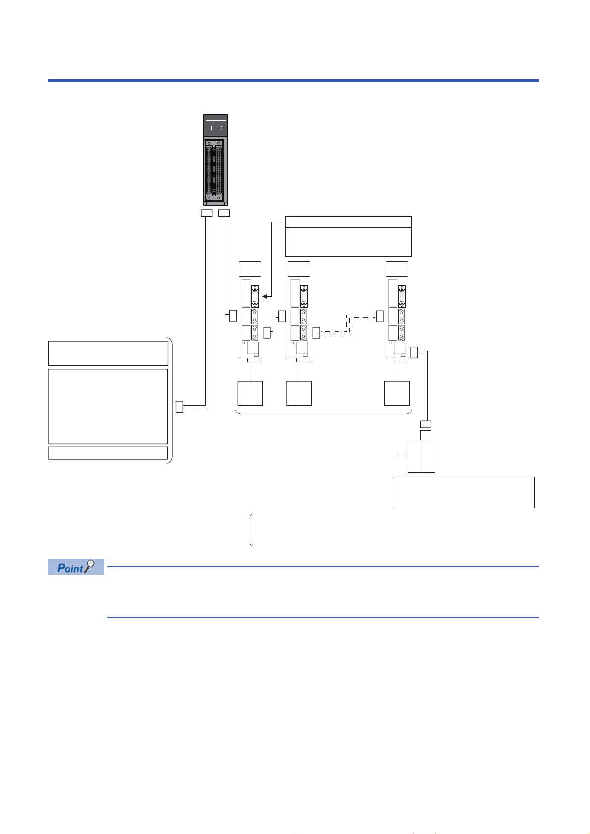
PERIPHERALS
RD77MS4
ERRRUN
AX
3
4
2
1
AX
SSCNET
µ
cable
External input
signal cable
Synchronous encoder via servo amplifier:
Q171ENC-W8 (Up to 4 modules via
MR-J4-B-RJ), etc.
RD77MS
• Upper stroke limit
• Lower stroke limit
• Proximity dog
External input signals of servo amplifier
Manual pulse generator/
Incremental synchronous encoder
× 1
Assigning the external input signals
for 20 points to any of the following
signals.
•
External command signal/Switching
signal
•
Upper stroke limit
•
Lower stroke limit
• Proximity dog
signal
•
Stop signal
Forced stop input (24 V DC)
Servo
motor
Servo
motor
Servo
motor
MR-J4(W)-B servo amplifier
MR-J3(W)-B servo amplifier
MR-JE-B(F) servo amplifier
Optical hub unit MR-MV200
Inverter FR-A700 series/FR-A800 series
Stepping motor driver AlphaStep/5-phase
manufactured by ORIENTAL MOTOR Co., Ltd.
Servo driver VC´ series/VPH series
manufactured by CKD NIKKI DENSO CO., LTD.
IAI electric actuator controller
manufactured by IAI Corporation
RD77MS2: Up to 2 axes
RD77MS4: Up to 4 axes
RD77MS8: Up to 8 axes
RD77MS16: Up to 16 axes
The following figure shows the peripherals when the RD77MS is used.
16
• The external input signal cannot be used depending on the connected device. Confirm the specification of
the connected device.
• When using RD77MS2, the external input signals that can be assigned are for 10 points.
Page 19
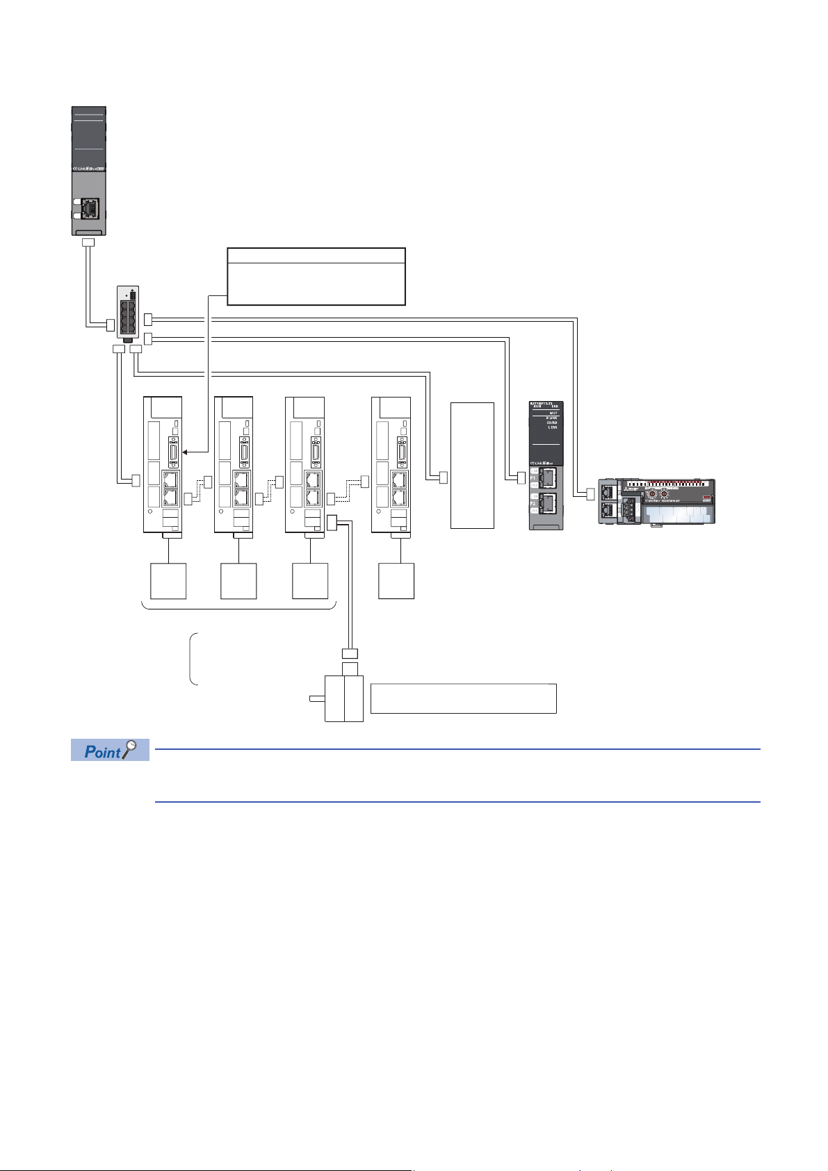
The following figure shows the peripherals when the RD77GF is used.
RD77GF4
ERRRUN
AX1-4
D LINK
SD/RD
L ERR
L ER
LINK
RD77GF4: Up to 4 axes
RD77GF8: Up to 8 axes
RD77GF16: Up to 16 axes
RD77GF32: Up to 32 axes
MR-J4-GF servo amplifier (Motion mode)
Servo
motor
Servo
motor
Servo
motor
MR-J4-GF
servo amplifier
(I/O mode)
Servo
motor
Another brand
drive unit
Remote I/OLocal station
CC-Link IE Field
Network cable
RD77GF
Switching hub
• Upper stroke limit
• Lower stroke limit
• Proximity dog
External input signals of servo amplifier
Synchronous encoder via servo amplifier:
Q171ENC-W8 (via MR-J4-_GF_-RJ)
• The external input signal cannot be used depending on the connected device. Confirm the specification of
the connected device.
17
Page 20
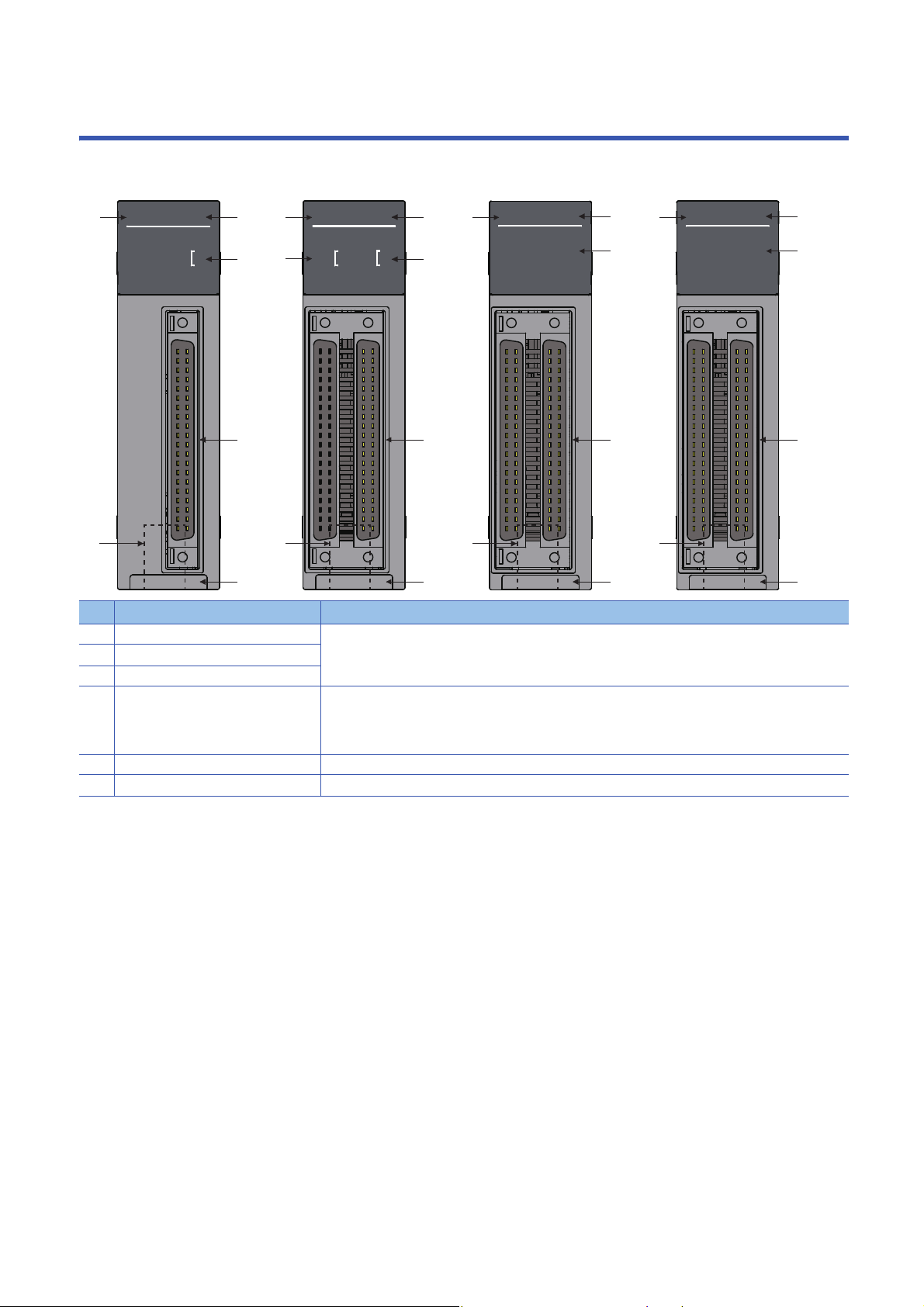
1 PART NAMES
RD77MS16
ERRRUN
AX1-16
RD77MS8
ERRRUN
AX1-8
RD77MS4
ERRRUN
AX
3
4
2
1
AX
RD77MS2
ERRRUN
2
1
AX
(6)
(4)
(5)
(1)
(2)
(3)
(2)
(3)
(1)
(4)
(6)
(5)
(6)
(5)
(4)
(2)
(3)
(1)
(3)
(2)
(3)
(1)
(4)
(6)
(5)
RD77MS2 RD77MS4 RD77MS8 RD77MS16
This chapter describes the part names of the Simple Motion module.
No. Name Description
(1) RUN LED For details, refer to the following.
(2) ERR LED
(3) Axis display LED
(4) External input connection connector Connects to a mechanical system input, manual pulse generator/incremental synchronous encoder, or
(5) SSCNET cable connector Connects to a servo amplifier.
(6) Serial No. marking Shows the serial No. printed on the rating plate.
Page 20 LED Display Specifications of the RD77MS
forced stop input.
For the signal layout, refer to the following.
Page 26 Specifications of Interfaces with External Devices of the RD77MS
18
1 PART NAMES
Page 21
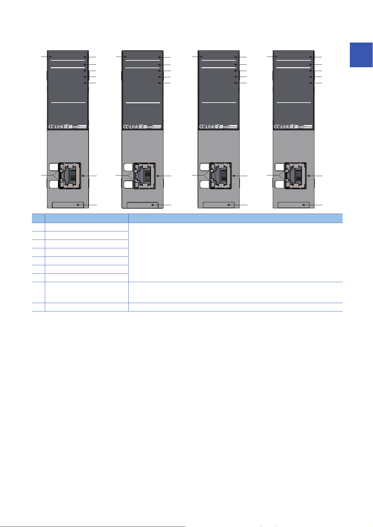
No. Name Description
RD77GF4
ERRRUN
AX1-4
D LINK
SD/RD
L ERR
L ER
LINK
RD77GF8
ERRRUN
AX1-8
D LINK
SD/RD
L ERR
L ER
LINK
RD77GF16
ERRRUN
AX1-16
D LINK
SD/RD
L ERR
L ER
LINK
RD77GF32
ERRRUN
AX1-32
D LINK
SD/RD
L ERR
L ER
LINK
RD77GF4 RD77GF8 RD77GF16
(2)
(3)
(4)
(8)
(7)
(1)
(5)
(6)
(9)
(2)
(3)
(4)
(8)
(7)
(1)
(5)
(6)
(9)
(2)
(3)
(4)
(8)
(7)
(1)
(5)
(6)
(9)
RD77GF32
(2)
(3)
(4)
(8)
(7)
(1)
(5)
(6)
(9)
(1) RUN LED For details, refer to the following.
(2) ERR LED
(3) Axis display LED
(4) D LINK LED
(5) SD/RD LED
(6) L ERR LED
(7) LEDs for CC-Link IE Field connector
(8) Connector for CC-Link IE Field Network
cable
(9) Serial No. marking Shows the serial No. printed on the rating plate.
Page 21 LED Display Specifications of the RD77GF
Connects to a slave station.
In the following manual, this connector is referred to as "PORT2", "P2", or "Port 2".
MELSEC iQ-R Simple Motion Module User's Manual (Network)
1
1 PART NAMES
19
Page 22

1.1 LED Display Specifications of the RD77MS
This section lists the LED display specifications of the RD77MS.
: OFF, : ON, ●: Flashing
Simple Motion
module status
Normal operation RUN
Operation failure RUN
Online module change RUN ●
LED display Description
ERR
RUN
ERR
ERR
RUN
ERR ●
ERR
RUN
ERR
AX1
AX2
AX3
AX4
AX1-8
AX1-16
AX1
AX2
AX3
AX4
AX1-8
AX1-16
AX1 ●
AX2
AX3
AX4
AX1-8 ●
AX1-16 ●
AX1
AX2
AX3
AX4
AX1-8
AX1-16
AX1
AX2
AX3
AX4
AX1-8
AX1-16
AX1
AX2
AX3
AX4
AX1-8
AX1-16
*1
*1
*2
*2
*3
*3
The axes stopped
The axes on standby
The axis in operation
Minor error
Moderate error
Watchdog timer error
Module remove selection in operation
Module change in operation
*1 When all axes are stopped or on standby, the AX LED turns OFF.
*2 When any of the axes is in operation, the AX LED turns ON.
*3 When an error occurs in any of the axes, the AX LED is flashing.
1 PART NAMES
20
1.1 LED Display Specifications of the RD77MS
Page 23

1.2 LED Display Specifications of the RD77GF
This section lists the LED display specifications of the RD77GF.
Simple Motion
module status
Normal operation RUN
Operation failure RUN
LED display Description
*1
ERR
RUN
ERR
ERR
RUN
ERR
RUN
ERR ●
RUN
ERR
AX1-4
*1
AX1-8
AX1-16
AX1-32
AX1-4
AX1-8
AX1-16
AX1-32
AX1-4 ●
AX1-8 ●
AX1-16 ●
AX1-32 ●
AX1-4
AX1-8
AX1-16
AX1-32
AX1-4 Flashing (500 ms interval): A data link faulty station detected
AX1-8
AX1-16
AX1-32
AX1-4 Major error
AX1-8
AX1-16
AX1-32
*1
*1
*2
*2
*2
*2
*3
*3
*3
*3
*4
*4
*4
*4
The axes stopped
The axes on standby
The axis in operation
Minor error (related to axis)
Minor error (general)
Flashing (200 ms interval): Moderate error
1
: OFF, : ON, ●: Flashing
*1 When all axes are stopped or on standby, the AX LED turns OFF.
*2 When any of the axes is in operation, the AX LED turns ON.
*3 When an error occurs in any of the axes, the AX LED is flashing.
*4 The AX LED does not turn OFF when the axis is in operation or a minor error (related to axis) has occurred.
Status LED display Description
Indicates the data link status. D LINK
D LINK ●
D LINK
Indicates the data sending/receiving
status.
Indicates the receive data and line error
status.
Indicates the port status. L ER Abnormal data received
Indicates the link status. LINK Link-up
SD/RD Data being sent or received
SD/RD Data not sent nor received
L ERR Abnormal data received
L ERR Normal data received
L ER Normal data received
LINK Link-down
*1
*1
*1
Data link (cyclic transmission being performed)
Data link (cyclic transmission stopped)
Data link not performed (disconnection)
: OFF, : ON, ●: Flashing
*1 The LED is always OFF in offline mode.
1 PART NAMES
1.2 LED Display Specifications of the RD77GF
21
Page 24

2 SPECIFICATIONS
This chapter describes the performance specifications of the RD77MS and the RD77GF.
2.1 Performance Specifications of the RD77MS
This section lists the performance specifications of the RD77MS.
Item RD77MS2 RD77MS4 RD77MS8 RD77MS16
Number of controlled axes 2 axes 4 axes 8 axes 16 axes
Operation cycle 0.444 ms/0.888 ms/1.777 ms/3.555 ms
Interpolation function 2-axis linear
interpolation, 2-axis
circular interpolation
Control method PTP (Point To Point) control, path control (linear, arc, and helix can be set), speed control, speed-
position switching control, position-speed switching control, speed-torque control
Control unit mm, inch, degree, pulse
Positioning data 600 data/axis (The 101st data to the 600th data can be set only with the engineering tool.)
Execution data backup function Parameters, positioning data, and block start data can be saved on flash ROM. (battery-less backup)
Positioning Positioning system PTP control: Incremental system/absolute system
Speed-position switching control: Incremental system/absolute system
Position-speed switching control: Incremental system
Path control: Incremental system/absolute system
Positioning range In absolute system
• -214748364.8 to 214748364.7 (m)
• -21474.83648 to 21474.83647 (inch)
• 0 to 359.99999 (degree)
• -2147483648 to 2147483647 (pulse)
In incremental system
• -214748364.8 to 214748364.7 (m)
• -21474.83648 to 21474.83647 (inch)
• -21474.83648 to 21474.83647 (degree)
• -2147483648 to 2147483647 (pulse)
In speed-position switching control (INC mode)/position-speed switching control
• 0 to 214748364.7 (m)
• 0 to 21474.83647 (inch)
• 0 to 21474.83647 (degree)
• 0 to 2147483647 (pulse)
In speed-position switching control (ABS mode)
0 to 359.99999 (degree)
Speed command 0.01 to 20000000.00 (mm/min)
0.001 to 2000000.000 (inch/min)
0.001 to 2000000.000 (degree/min)
1 to 1000000000 (pulse/s)
Acceleration/deceleration process Trapezoidal acceleration/deceleration, S-curve acceleration/deceleration
Acceleration/deceleration time 1 to 8388608 (ms) (Four patterns can be set for each of acceleration time and deceleration time.)
Rapid stop deceleration time 1 to 8388608 (ms)
2-, 3-, or 4-axis linear interpolation, 2-axis circular interpolation, 3-axis
helical interpolation
*1
*2
22
2 SPECIFICATIONS
2.1 Performance Specifications of the RD77MS
Page 25

Item RD77MS2 RD77MS4 RD77MS8 RD77MS16
Starting time*3Operation cycle
External wiring connection system 40-pin connector
Applicable
wire size
External input wiring connector A6CON1, A6CON2, A6CON4 (sold separately)
Manual pulse generator/
Incremental synchronous
encoder input maximum
frequency
Manual pulse generator 1 pulse input magnification 1 to 10000 times
Flash ROM write count Max. 100000 times
Number of occupied I/O points 32 points (I/O assignment: Intelligent function module 32 points)
Internal current consumption (5 V DC) 1.0 A
External
dimensions
Mass 0.22 kg 0.23 kg
0.444 ms
Operation cycle
0.888 ms
Operation cycle
1.777 ms
Operation cycle
3.555 ms
When A6CON1 or A6CON4 is used 0.088 to 0.3 mm2 (AWG28 to AWG22) stranded wire
*4
When A6CON2 is used 0.088 to 0.24 mm
Height 106 mm (4.17 inch)
Width 27.8mm (1.09inch)
Depth 110 mm (4.33 inch)
Maximum number
of axes: 1 axis
Maximum number
of axes: 2 axes
Maximum number
of axes: 4 axes
Maximum number
of axes: 4 axes
Maximum number
of axes: 8 axes
Maximum number
of axes: 12 axes
Maximum number
of axes: 8 axes
Maximum number
of axes: 12 axes
Maximum number
of axes: 16 axes
Maximum number
of axes: 8 axes
Maximum number
of axes: 12 axes
Maximum number
of axes: 16 axes
Differential-output
type
Open-collector
type
0.7 ms
0.7 ms
0.74 ms
1.1 ms
1.32 ms
1.46 ms
1.1 ms
1.46 ms
1.59 ms
0.92 ms
1.12 ms
1.52 ms
Up to 1 Mpulses/s
Up to 200 kpulses/s
2
(AWG28 to AWG24) stranded wire
*1 The speed-position switching control (ABS mode) can be used only when the control unit is "degree".
*2 When "Speed control 10 multiplier setting for degree axis function" is valid, the setting range is 0.01 to 20000000.00 (degree/min).
*3 Time from accepting the positioning start signal until BUSY signal turns ON.
*4 Use cables with outside diameter of 1.3 mm (0.05 inch) or shorter to connect 40 cables to the connector. In addition, consider the
amount of current to be used and select appropriate cables.
2
2 SPECIFICATIONS
2.1 Performance Specifications of the RD77MS
23
Page 26

2.2 Performance Specifications of the RD77GF
This section lists the performance specifications of the RD77GF.
Item RD77GF4 RD77GF8 RD77GF16 RD77GF32
Number of controlled axes 4 axes 8 axes 16 axes 32 axes
Operation cycle 0.50 ms/1.00 ms/2.00 ms/4.00 ms
Interpolation function 2-, 3-, or 4-axis linear interpolation
2-axis circular interpolation
3-axis helical interpolation
Control method PTP (Point To Point) control, path control (linear, and arc can be set), speed control, speed-position
Control unit mm, inch, degree, pulse
Positioning data 600 data/axis (All the data points can be set with the buffer memory.)
Execution data backup function Parameters, positioning data, and block start data can be saved on flash ROM. (battery-less backup)
Positioning Positioning system PTP control: Incremental system/absolute system
Positioning range In absolute system
Speed command 0.01 to 20000000.00 (mm/min)
Acceleration/deceleration process Trapezoidal acceleration/deceleration, S-curve acceleration/deceleration
Acceleration/deceleration time 1 to 8388608 (ms) (Four patterns can be set for each of acceleration time and deceleration time.)
Rapid stop deceleration time 1 to 8388608 (ms)
Starting time 0.2 ms to 5.0 ms
Manual pulse
generator
Flash ROM write count Max. 100000 times
Number of occupied I/O points 32 points (I/O assignment: Intelligent function module 32 points) 64 points (I/O
Internal current consumption (5 V DC) 1.1 A
External
dimensions
Mass 0.23 kg
Signal input form Link device
1 pulse input magnification 1 to 10000 times
Height 106 mm (4.17 inch)
Width 27.8 mm (1.09 inch)
Depth 110 mm (4.33 inch)
switching control, position-speed switching control, speed-torque control
Speed-position switching control: Incremental system/absolute system
Position-speed switching control: Incremental system
Path control: Incremental system/absolute system
• -214748364.8 to 214748364.7 (m)
• -21474.83648 to 21474.83647 (inch)
• 0 to 359.99999 (degree)
• -2147483648 to 2147483647 (pulse)
In incremental system
• -214748364.8 to 214748364.7 (m)
• -21474.83648 to 21474.83647 (inch)
• -21474.83648 to 21474.83647 (degree)
• -2147483648 to 2147483647 (pulse)
In speed-position switching control (INC mode)/position-speed switching control
• 0 to 214748364.7 (m)
• 0 to 21474.83647 (inch)
• 0 to 21474.83647 (degree)
• 0 to 2147483647 (pulse)
In speed-position switching control (ABS mode)
0 to 359.99999 (degree)
0.001 to 2000000.000 (inch/min)
0.001 to 2000000.000 (degree/min)
1 to 1000000000 (pulse/s)
*2
*1
assignment: Intelligent
function module 64
points)
*1 The speed-position switching control (ABS mode) can be used only when the control unit is "degree".
*2 When "Speed control 10 multiplier setting for degree axis function" is valid, the setting range is 0.01 to 20000000.00 (degree/min).
2 SPECIFICATIONS
24
2.2 Performance Specifications of the RD77GF
Page 27

The performance specifications of CC-Link IE Field Network is shown below.
Item RD77GF4 RD77GF8 RD77GF16 RD77GF32
Maximum number of link points per
network
Maximum
number of link
points per
station
Safety
communications
Inter-module synchronization cycle
synchronization communication)
Transient transmission 1: N communication (such as monitor, program upload/download)
Transient transmission capacity 1920 bytes maximum
Maximum number of transient transmissions per link
scan
Communication speed 1 Gbps
Network topology Line topology, star topology
Communication cable • Ethernet cable which satisfies 1000BASE-T standard:
Maximum station-to-station distance 100 m (conforms to ANSI/TIA/EIA-568-B (Category 5e))
Overall cable distance Single master
Number of cascade connections 4 levels maximum
Maximum number of
connectable stations
Maximum number of networks 239
Communication method Token passing
Master station RX 16K points (16384 points, 2K bytes)
Local station
Maximum number of safety
connectable stations per network
Maximum number of safety
connections per network
Maximum number of safety
connections per station
Maximum number of link points per
safety connection
*1
*2
configuration
Single master
configuration
RX 16K points (16384 points, 2K bytes)
RY 16K points (16384 points, 2K bytes)
RWr 8K points (8192 points, 16K bytes)
RWw 8K points (8192 points, 16K bytes)
RY 16K points (16384 points, 2K bytes)
RWr 8K points (8192 points, 16K bytes)
RWw 8K points (8192 points, 16K bytes)
RX 2K points (2048 points, 256 bytes)
RY 2K points (2048 points, 256 bytes)
RWr 1K points (1024 points, 2K bytes)
RWw 1K points (1024 points, 2K bytes)
(with
256 points when communication mode is "High-Speed"
256 points when communication mode is "High-Speed"
121 stations
1814 connections
120 connections
8 words (input: 8 words, output: 8 words)
0.50 ms/1.00 ms/2.00 ms/4.00 ms
Dedicated instructions from sequence programs
4
Category 5e or higher, straight cable (double shielded, STP)
• RJ45 connector
Line topology: 12000 m (when 121 stations are connected)
Star topology: Depends on the system configuration.
121 stations (master station: 1, slave station: 120)
*3
2
*1 The maximum number of points that a master station can assign to one station. A local station can receive the range assigned to other
stations using the cyclic transmission function.
*2 The cycle that each module performs the synchronous control via a network using the synchronous communication function.
*3 A switching hub supporting synchronous communication is required for the star topology.
2 SPECIFICATIONS
2.2 Performance Specifications of the RD77GF
25
Page 28

2.3 Specifications of Interfaces with External Devices
of the RD77MS
Electrical specifications of input signals
External input signal
■Specifications of external input signal
Item Specifications
Signal name Input signal (SIN)
Number of input points RD77MS2: 10 points, RD77MS4/RD77MS8/RD77MS16: 20 points
Input method Positive common/Negative common shared
Common terminal arrangement 4 points/common (Common contact: COM)
Isolation method Photocoupler
Rated input voltage 24 V DC
Rated input current (I
Operating voltage range 19.2 to 26.4 V DC (24 V DC+10/-20%, ripple ratio 5% or less)
ON voltage/current 17.5 V DC or more/3.5 mA or more
OFF voltage/current 7 V DC or less/1 mA or less
Input resistance Approx. 6.8 kΩ
Response time OFF ON 1 ms or less
) Approx. 5 mA
IN
ON OFF
Forced stop input
■Specifications of forced stop input signal
Item Specifications
Number of input points 1 point
Input method Positive common/Negative common shared
Common terminal arrangement 1 point/common (Common contact: EMI.COM)
Isolation method Photocoupler
Rated input voltage 24 V DC
Rated input current (I
Operating voltage range 19.2 to 26.4 V DC (24 V DC+10/-20%, ripple ratio 5% or less)
ON voltage/current 17.5 V DC or more/3.5 mA or more
OFF voltage/current 7 V DC or less/1 mA or less
Input resistance Approx. 6.8 kΩ
Response time OFF ON 4 ms or less
) Approx. 5 mA
IN
ON OFF
26
2 SPECIFICATIONS
2.3 Specifications of Interfaces with External Devices of the RD77MS
Page 29
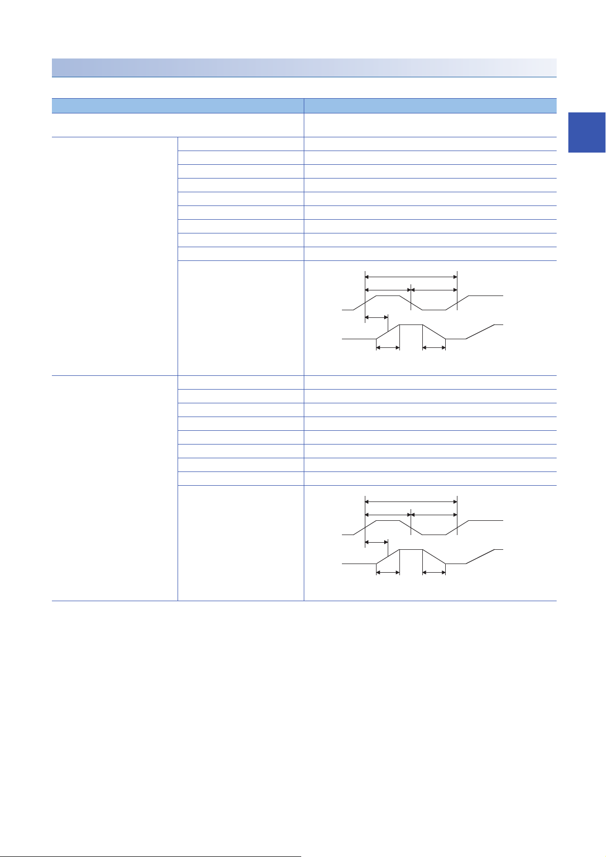
Manual pulse generator/Incremental synchronous encoder input
A-phase
0.5 μs or more
1 μs or more
B-phase
0.25 μs
or less
0.25 μs
or less
0.5 μs or more
0.25 μs
or more
(Note): Duty ratio 50%
A-phase
2.5 μs or more
5 μs or more
B-phase
1.2 μs
or less
1.2 μs
or less
2.5 μs or more
1.2 μs
or more
(Note): Duty ratio 50%
■Specifications of manual pulse generator/incremental synchronous encoder
Item Specifications
Signal input form
Differential-output type
(26LS31 or equivalent)
*1
Maximum input pulse frequency 1 Mpulses/s (After magnification by 4, up to 4 Mpulses/s)
Pulse width 1 s or more
Leading edge/trailing edge time 0.25 s or less
Phase difference 0.25 s or more
Rated input voltage 5.5 V DC or less
High-voltage 2.0 to 5.25 V DC
Low-voltage 0 to 0.8 V DC
Differential voltage 0.2 V
Cable length Up to 30 m (98.43 ft.)
Example of waveform
A-phase/B-phase (Magnification by 4/Magnification by 2/Magnification by 1),
PULSE/SIGN
*2
2
Voltage-output type/Open-collector
type (5 V DC)
Maximum input pulse frequency 200 kpulses/s (After magnification by 4, up to 800 kpulses/s)
Pulse width 5 s or more
Leading edge/trailing edge time 1.2 s or less
Phase difference 1.2 s or more
Rated input voltage 5.5 V DC or less
High-voltage 3.0 to 5.25 V DC/2 mA or less
Low-voltage 0 to 1.0 V DC/5 mA or more
Cable length Up to 10 m (32.81 ft.)
Example of waveform
*1 Set the signal input form in "[Pr.24] Manual pulse generator/Incremental synchronous encoder input selection".
*2
2 SPECIFICATIONS
2.3 Specifications of Interfaces with External Devices of the RD77MS
27
Page 30

[Pr.24]
Manual pulse generator/Incremental
synchronous encoder input selection
A-phase/B-phase
[Pr.151] Manual pulse generator/Incremental synchronous encoder input logic
selection
Positive logic Negative logic
Forward run Reverse run Forward run Reverse run
PULSE/SIGN
*2 Maximum input pulse frequency is magnified by 4, when "A-phase/B-phase Magnification by 4" is set in "[Pr.24] Manual pulse generator/
Incremental synchronous encoder input selection".
Forward run Reverse run
HIGH LOW
Forward run Reverse run
HIGHLOW
28
2 SPECIFICATIONS
2.3 Specifications of Interfaces with External Devices of the RD77MS
Page 31

2.4 External Circuit Design
Forced stop
EMI
EMI.
COM
R61P RD77MSRnCPU
24 V DC
Forced stop circuit
The forced stop of all servo amplifiers is possible in a lump by using the forced stop input of Simple Motion module. After
forced stop, the forced stop factor is removed and the forced stop canceled. (The servo error detection signal does not turn on
with the forced stop.)
[RD77MS]
A wiring example which uses a Simple Motion module for the forced stop input is shown below. Set "[Pr.82] Forced stop valid/
invalid selection" to "0: Valid (External input signal)".
2
2 SPECIFICATIONS
2.4 External Circuit Design
29
Page 32

[RD77GF]
FG
1
2
3
X01
X12
X23
X34
X45
X56
7
X78
X89
X910
XA11
XB12
XC13
XD14
XE15
XF16
COM17
COM18
+24V
24G
X6
1
2
3
R61P RD77GFRnCPU
Remote input
module
CC-Link IE
Field Network
X0
COM
Forced stop24 V DC
<Remote input module NZ2GF2B1(N)-16D>
Signal name
Pin
No.
Not insulated
UNIT POWER
CABLE
Input terminal block
Module power supply/
FG terminal block
*1
Module power
supply
Forced stop
24 V DC
A wiring example which uses a remote input module (NZ2GF2B1(N)-16D) for the forced stop input is shown below. Set
"[Pr.82] Forced stop valid/invalid selection" to "3: Valid (Link device)", and set forced stop signals (EMI) ([Pr.900] to [Pr.903])
according to the input modules.
*1 Only one wire can be connected to a terminal of the terminal block for module power supply and FG. Multiple wires cannot be connected
to a terminal. Connecting two or more wires may cause a poor contact.
It is also possible to use the forced stop signal of the servo amplifier. Operation status of the emergency stop, servo amplifier
forced stop and the Motion controller forced stop are as follows.
Item Operation when the
signal is turned on
Emergency stop Servo OFF The power supply of the servo amplifier is shut off by external circuit, and the servomotor stops.
Servo amplifier
forced stop
Motion controller
forced stop
Shut-off the main circuit power supply of a servo amplifier when an emergency stop, alarm, servo amplifier forced stop, or
motion controller forced stop occurs. Make sure to use molded-case circuit breakers (MCCB) for input wires of a servo
amplifier power supply. For details, refer to the servo amplifier instruction manual.
30
2 SPECIFICATIONS
2.4 External Circuit Design
Remarks
A stop command from the external circuit to the servo amplifier is output, and the servo amplifier stops the
servomotor.
A stop command from the Simple Motion module to the servo amplifier is output, and the servo amplifier
stops the servomotor.
Page 33

3 FUNCTION LIST
There are restrictions in the function that can be used by the software of the Simple Motion module and the version of
engineering tool. Refer to the following for details.
MELSEC iQ-R Simple Motion Module User's Manual (Application)
3.1 Control Functions
The Simple Motion module has several functions. Refer to the following for details on each function.
MELSEC iQ-R Simple Motion Module User's Manual (Application)
In this manual, the Simple Motion module functions are categorized and explained as follows.
Main functions
Home position return control
"Home position return control" is a function that established the start point for carrying out positioning control (Machine home
position return), and carries out positioning toward that start point (Fast home position return). This is used to return a
workpiece, located at a position other than the home position when the power is turned ON or after positioning stop, to the
home position. The "home position return control" is pre-registered in the Simple Motion module as the "Positioning start data
No. 9001 (Machine home position return)", and "Positioning start data No. 9002 (Fast home position return)".
3
Major positioning control
This control is carried out using the "Positioning data" stored in the Simple Motion module. Positioning control, such as
position control and speed control, is executed by setting the required items in this "positioning data" and starting that
positioning data. An "operation pattern" can be set in this "positioning data", and with this whether to carry out control with
continuous positioning data (ex.: positioning data No. 1, No. 2, No. 3, etc.) can be set.
High-level positioning control
This control executes the "positioning data" stored in the Simple Motion module using the "block start data". The following
types of applied positioning control can be carried out.
• Random blocks, handling several continuing positioning data items as "blocks", can be executed in the designated order.
• "Condition judgment" can be added to position control and speed control.
• The operation of the positioning data that is set for multiple axes can be started simultaneously. (Command is output
simultaneously to multiple servo amplifiers.)
• The designated positioning data can be executed repeatedly,
etc.
Manual control
The Simple Motion module executes the random positioning operation by inputting a signal into the Simple Motion module
from an external device.
Use this manual control to move the workpiece to a random position (JOG operation), and to finely adjust the positioning
(inching operation, manual pulse generator operation), etc.
Expansion control
The following controls other than the positioning control can be executed.
• Speed control and torque control not including position loop for the command to servo amplifier (Speed-torque control).
• Synchronous control with gear, shaft, change gear and cam not by mechanical, but by software use "advanced
synchronous control parameter", and is synchronized with input axis (Advanced synchronous control).
3 FUNCTION LIST
3.1 Control Functions
31
Page 34

The outline of the main functions for positioning control with the Simple Motion module is described below.
Main functions Details
Home position
return control
Major
positioning
control
High-level
positioning
control
Machine home position return control Mechanically establishes the positioning start point using a proximity dog, etc.
Fast home position return control Positions a target to the home position address ([Md.21] Machine feed value) stored in the Simple
Position
control
Speed
control
Speed-position switching control First, carries out speed control, and then carries out position control (positioning with designated
Position-speed switching control First, carries out position control, and then carries out speed control (continuous output of the
Other
control
Block start (Normal start) With one start, executes the positioning data in a random block with the set order.
Condition start Carries out condition judgment set in the "condition data" for the designated positioning data, and
Wait start Carries out condition judgment set in the "condition data" for the designated positioning data, and
Simultaneous start Simultaneously executes the designated positioning data of the axis designated with the "condition
Repeated start (FOR loop) Repeats the program from the block start data set with the "FOR loop" to the block start data set in
Repeated start (FOR condition) Repeats the program from the block start data set with the "FOR condition" to the block start data set
Linear control
(1-axis linear control)
(2-axis linear
interpolation control)
(3-axis linear
interpolation control)
(4-axis linear
interpolation control)
Fixed-feed control
(1-axis fixed-feed control)
(2-axis fixed-feed control)
(3-axis fixed-feed control)
(4-axis fixed-feed control)
2-axis circular
interpolation control
3-axis helical
interpolation control
Speed control
(1-axis speed control)
(2-axis speed control)
(3-axis speed control)
(4-axis speed control)
Current value changing Changes the feed current value ([Md.20]) to the address set in the positioning data.
NOP instruction No execution control method. When NOP instruction is set, this instruction is not executed and the
JUMP instruction Unconditionally or conditionally jumps to designated positioning data No.
LOOP Carries out loop control with repeated LOOP to LEND.
LEND Returns to the beginning of the loop control with repeated LOOP to LEND.
In the data setting method, no axis movement occurs since the current position is set as the home
position.
(Positioning start No. 9001)
Motion module using machine home position return. (Positioning start No. 9002)
Positions a target using a linear path to the address set in the positioning data or to the position
designated with the movement amount.
Positions a target by the movement amount designated with the amount set in the positioning data.
(With fixed-feed control, the "[Md.20] Feed current value" is set to "0" when the control is started.
With 2-, 3-, or 4-axis fixed-feed control, the fixed-feed is fed along a linear path obtained by
interpolation.)
Positions a target using an arc path to the address set in the positioning data, or to the position
designated with the movement amount, sub point or center point.
Positions a target using a helical path to a specified position. (Specify the position by specifying the
end point address directly or by specifying the relative distance from the current position (movement
amount).)
Continuously outputs the command corresponding to the command speed set in the positioning
data.
address or movement amount) by turning the "speed-position switching signal" ON.
command corresponding to the designated command speed) by turning the "position-speed
switching signal" ON.
The following two methods can be used.
(The machine feed value ([Md.21]) cannot be changed.)
• Current value changing using positioning data
• Current value changing using current value changing start No. (No. 9003)
operation of the next data is started.
then executes the "block start data".
When the condition is established, the "block start data" is executed. When not established, that
"block start data" is ignored, and the next point's "block start data" is executed.
then executes the "block start data".
When the condition is established, the "block start data" is executed. When not established, stops
the control until the condition is established. (Waits.)
data". (Outputs commands at the same timing.)
"NEXT" for the designated number of times.
in "NEXT" until the conditions set in the "condition data" are established.
32
3 FUNCTION LIST
3.1 Control Functions
Page 35

Main functions Details
Manual
control
Inter-module synchronization function Synchronizes the control timings among multiple modules on the same base.
Expansion
control
JOG operation Outputs a command to servo amplifier while the JOG start signal is ON.
Inching operation Outputs commands corresponding to minute movement amount by manual operation to servo
amplifier.
(Performs fine adjustment with the JOG start signal.)
Manual pulse generator operation Outputs pulses commanded with the manual pulse generator to servo amplifier.
Speed-torque control Carries out the speed control or torque control that does not include the position loop for the
command to servo amplifier by switching control mode.
Advanced synchronous control Carries out the synchronous control that synchronizes with input axis by setting the system such as
gear, shaft, change gear and cam to the "advanced synchronous control parameter".
In "major positioning control" ("high-level positioning control"), "Operation pattern" can be set to designate whether to continue
executing positioning data. Outlines of the "operation patterns" are given below.
[Da.1] Operation pattern Details
Independent positioning control (positioning complete) When "independent positioning control" is set for the operation pattern of the started positioning
Continuous positioning control When "continuous positioning control" is set for the operation pattern of the started positioning data,
Continuous path control When "continuous path control" is set for the operation pattern of the started positioning data, the
data, only the designated positioning data will be executed, and then the positioning will end.
after the designated positioning data is executed, the program will stop once, and then the next
following positioning data will be executed.
designated positioning data will be executed, and then without decelerating, the next following
positioning data will be executed.
3
3 FUNCTION LIST
3.1 Control Functions
33
Page 36

Sub functions
When the main functions are executed, this function compensates and limits controls, or adds functions.
The outline of the functions that assist positioning control using the Simple Motion module is described below.
Sub function Details
Functions
characteristic to
machine home
position return
Functions that
compensate
control
Functions that
limit control
Functions that
change control
details
Functions
related to
positioning start
Absolute position system This function restores the absolute position of designated axis.
Functions
related to
positioning stop
Home position return retry
function [RD77MS]
Home position shift function
[RD77MS]
Backlash compensation
function
Electronic gear function By setting the movement amount per pulse, this function can freely change the machine movement
Near pass function
Speed limit function If the command speed exceeds "[Pr.8] Speed limit value" during control, this function limits the
Torque limit function If the torque generated by the servomotor exceeds "[Pr.17] Torque limit setting value" during control, this
Software stroke limit function If a command outside of the upper/lower limit stroke limit setting range, set in the parameters, is issued,
Hardware stroke limit function This function carries out deceleration stop with the hardware stroke limit switch.
Forced stop function This function stops all axes of the servo amplifier with the forced stop signal.
Speed change function This function changes the speed during positioning.
Override function This function changes the speed within a percentage of 0 to 300% during positioning. This is executed
Acceleration/deceleration
time change function
Torque change function This function changes the "torque limit value" during control.
Target position change
function
Pre-reading start function This function shortens the virtual start time.
Stop command processing for
deceleration stop function
Continuous operation
interrupt function
Step function This function temporarily stops the operation to confirm the positioning operation during debugging, etc.
*1
This function retries the home position return with the upper/lower limit switches during the machine home
position return. This allows machine home position return to be carried out even if the axis is not returned
to before the proximity dog with JOG operation, etc.
After returning to the machine home position, this function compensates the position by the designated
distance from the machine home position and sets that position as the home position address.
This function compensates the mechanical backlash amount. Feed commands equivalent to the set
backlash amount are output each time the movement direction changes.
amount per commanded pulse.
When the movement amount per pulse is set, a flexible positioning system that matches the machine
system can be structured.
This function suppresses the machine vibration when the speed is changed during continuous path control
in the interpolation control.
commanded speed to within the "[Pr.8] Speed limit value" setting range.
function limits the generated torque to within the "[Pr.17] Torque limit setting value" setting range.
this function will not execute positioning for that command.
Set the new speed in the speed change buffer memory ([Cd.14] New speed value), and change the speed
with the speed change request ([Cd.15]).
using "[Cd.13] Positioning operation speed override".
This function changes the acceleration/deceleration time during speed change.
This function changes the target position during positioning.
Position and speed can be changed simultaneously.
Function that selects a deceleration curve when a stop cause occurs during deceleration stop processing
to speed 0.
This function interrupts continuous operation. When this request is accepted, the operation stops when the
execution of the current positioning data is completed.
The operation can be stopped at each "automatic deceleration" or "positioning data".
34
3 FUNCTION LIST
3.1 Control Functions
Page 37

Sub function Details
Other functions Skip function This function stops (decelerates to a stop) the positioning being executed when the skip signal is input,
M code output function This function issues a command for a sub work (clamp or drill stop, tool change, etc.) according to the
Teaching function This function stores the address positioned with manual control into the "[Da.6] Positioning address/
Command in-position function This function calculates the remaining distance for the Simple Motion module to reach the positioning stop
Acceleration/deceleration
processing function
Deceleration start flag
function
Follow up function This function monitors the motor rotation amount with the servo turned OFF, and reflects it on the feed
Speed control 10 multiplier
setting for degree axis
function
Operation setting for
incompletion of home position
return function
and carries out the next positioning.
code No. (0 to 65535) that can be set for each positioning data.
The M code output timing can be set for each positioning data.
movement amount" having the designated positioning data No. ([Cd.39]).
position. When the value is less than the set value, the "command in-position flag" is set to "1".
When using another auxiliary work before ending the control, use this function as a trigger for the sub
work.
This function adjusts the acceleration/deceleration.
Function that turns ON the flag when the constant speed status or acceleration status switches to the
deceleration status during position control, whose operation pattern is "Positioning complete", to make the
stop timing known.
current value.
This function executes the positioning control by the 10 times speed of the command speed and the speed
limit value when the setting unit is "degree".
This function is provided to select whether positioning control is operated or not, when the home position
return request flag is ON.
*1 The near pass function is featured as standard and is valid only for setting continuous path control for position control. It cannot be set to
be invalid with parameters.
3
3 FUNCTION LIST
3.1 Control Functions
35
Page 38

Common functions
Common control using the Simple Motion module for "Parameter initialization function" or "Execution data backup function"
can be carried out.
The outline of the functions executed as necessary is described below.
Common functions Details
Parameter initialization function This function returns the setting data stored in the buffer memory/internal memory and flash ROM/internal
Execution data backup function This function writes the execution data being used in the control into the flash ROM/internal memory
External input signal select function [RD77MS]
Link device external signal assignment function
[RD77GF]
History monitor function This function monitors start history and current value history of all axes.
Amplifier-less operation function This function executes the positioning control of Simple Motion module without connecting to the servo
Virtual servo amplifier function This function executes the operation as the axis (virtual servo amplifier axis) that operates only command
Driver communication function [RD77MS] This function uses the "Master-slave operation function" of servo amplifier. The Simple Motion module
Mark detection function This function is used to latch any data at the input timing of the mark detection signal (DI).
Optional data monitor function [RD77MS] This function is used to store the data selected by user up to 4 data per axis to buffer memory and monitor
Event history function This function collects errors and event information occurred in the Simple Motion module in the CPU
Connect/disconnect function of SSCNET
communication [RD77MS]
Servo cyclic transmission function [RD77GF] This function reads and writes objects of slave devices with cyclic transmission.
Servo transient transmission function [RD77GF] This function reads and writes objects of slave devices with transient transmission.
Online module change [RD77MS] Allows to replace a module without stopping the system. For procedures for the online module change,
Test mode This mode executes the test operation and adjustment of axes using an engineering tool.
Servo parameter change function [RD77GF] This function transfers servo parameters. Servo parameters, which are controlled by servo amplifiers, can
Hot line forced stop function This function is used to execute deceleration stop safety for other axes when the servo alarm occurs in the
memory (nonvolatile) of Simple Motion module to the default values.
The following two methods can be used.
• Method using a program
• Method using an engineering tool
(nonvolatile).
The following two methods can be used.
• Method using a program
• Method using an engineering tool
This function sets the input type, input terminal, signal logic and input filter for each external input signal of
each axis (upper/lower stroke limit signal (FLS/RLS), proximity dog signal (DOG), and stop signal
(STOP)).
The function enables the assignment of external input signal of each axis to any terminals of the external
input connection connector on the Simple Motion module.
[RD77GF]
This function sets the input type and signal logic for each external input signal of each axis (upper/lower
stroke limit signal (FLS/RLS), proximity dog signal (DOG), and stop signal (STOP)).
This function assigns link devices to external signals of the Simple Motion module.
amplifiers.
It is used to debug the program at the start-up of the device or simulate the positioning operation.
(instruction) virtually without servo amplifiers.
controls the master axis and the slave axis is controlled by data communication between servo amplifiers
(driver communication) without Simple Motion module.
them.
module, and saves them to an SD memory card.
The error history can be checked even after the power OFF or reset by holding the error contents in the
CPU module.
Temporarily connect/disconnect of SSCNET communication is executed during system's power supply
ON. This function is used to exchange the servo amplifiers or SSCNET cables.
refer to the following.
MELSEC iQ-R Online Module Change Manual
be changed with a Simple Motion module.
servo amplifier MR-JE-B(F).
36
3 FUNCTION LIST
3.1 Control Functions
Page 39

3.2 Combination of Main Functions and Sub
Functions
With positioning control using the Simple Motion module, the main functions and sub functions can be combined and used as
necessary. A list of the main function and sub function combinations is shown below.
Combination of main functions and operation patterns
: Combination possible
: Combination limited
: Combination not possible
Main functions Combination with operation pattern
Home position return
control
Major positioning control Position control 1-axis linear control
Manual control JOG operation, inching operation
Expansion control Speed-torque control
Machine home position return control
Fast home position return control
2-, 3-, or 4-axis linear interpolation control
1-axis fixed-feed control (Continuous path control cannot be set)
2-, 3-, or 4-axis fixed-feed control (interpolation) (Continuous path control cannot be set)
2-axis circular interpolation control
3-axis helical interpolation control
Speed control (1- to 4-axis) (Only independent positioning control can be set)
Speed-position switching control (Continuous path control cannot be set)
Position-speed switching control (Only independent positioning control can be set)
Other control Current value changing (Continuous path control cannot be set)
NOP instruction
JUMP instruction
LOOP to LEND
Manual pulse generator operation
Advanced synchronous control (output axis)
*1
3
*1 The operation pattern is one of the "positioning data" setting items.
3 FUNCTION LIST
3.2 Combination of Main Functions and Sub Functions
37
Page 40

Combination of main functions and sub functions
: Combination possible
: Combination limited
: Combination not possible
Main functions Functions characteristic to
machine home position return
Home
position
return
control
Major
positioning
control
Manual
control
Expansion
control
Home
position
return retry
function
Machine home position return control *1[RD77MS]
Fast home position return control
Position
control
Speed control (1- to 4-axis)
Speed-position switching control
Position-speed switching control
Other
control
JOG operation, inching operation
Manual pulse generator operation
Speed-torque control
Advanced synchronous control (output
axis)
1-axis linear control
2-, 3-, or 4-axis linear
interpolation control
1-axis fixed-feed control
2-, 3-, or 4-axis fixed-feed
control (interpolation)
2-axis circular interpolation
control
3-axis helical interpolation
control
Current value changing
NOP instruction
JUMP instruction
LOOP to LEND
*3
[RD77GF]
Home
position shift
function
[RD77MS]
*3[RD77GF]
Functions that compensate control
Backlash
compensation
Electronic
gear function
function
[RD77MS]
*3[RD77GF]
[RD77MS]
*3[RD77GF]
Near pass
function
*2
[RD77MS]
[RD77GF]
*2
*1 Home position return retry function cannot be used during the scale origin signal detection method machine home position return.
*2 The near pass function is featured as standard and is valid only for setting continuous path control for position control.
*3 Availability of the function depends on the home position return specifications of the servo amplifier.
3 FUNCTION LIST
38
3.2 Combination of Main Functions and Sub Functions
Page 41

: Always combine
: Combination possible
: Combination limited
: Combination not possible
Main functions Functions that limit control
Home
position
return
control
Major
positioning
control
Manual
control
Expansion
control
Speed limit
function
Machine home position return control [RD77MS]
Fast home position return control
Position
control
Speed control (1- to 4-axis)
Speed-position switching control
Position-speed switching control
Other
control
JOG operation, inching operation
Manual pulse generator operation
Speed-torque control
Advanced synchronous control (output
axis)
1-axis linear control
2-, 3-, or 4-axis linear
interpolation control
1-axis fixed-feed control
2-, 3-, or 4-axis fixed-feed
control (interpolation)
2-axis circular interpolation
control
3-axis helical interpolation
control
Current value changing
NOP instruction
JUMP instruction
LOOP to LEND
*1
[RD77GF]
Torque limit
function
[RD77MS]
*1[RD77GF]
Software
stroke limit
function
[RD77MS]
*1[RD77GF]
Hardware
stroke limit
function
[RD77MS]
*1[RD77GF]
Forced stop
function
[RD77MS]
*1[RD77GF]
3
*1 Availability of the function depends on the home position return specifications of the servo amplifier.
3 FUNCTION LIST
3.2 Combination of Main Functions and Sub Functions
39
Page 42

: Combination possible
: Combination limited
: Combination not possible
Main functions Functions that change control details
Home
position
return
control
Major
positioning
control
Manual
control
Expansion
control
Speed change
function
Machine home position return control *1[RD77MS]
[RD77GF]
Fast home position return control
Position
control
Speed control (1- to 4-axis)
Speed-position switching control
Position-speed switching control
Other
control
JOG operation, inching operation
Manual pulse generator operation
Speed-torque control
Advanced synchronous control (output
axis)
1-axis linear control
2-, 3-, or 4-axis linear
interpolation control
1-axis fixed-feed control
2-, 3-, or 4-axis fixed-feed
control (interpolation)
2-axis circular interpolation
control
3-axis helical interpolation
control
Current value changing
NOP instruction
JUMP instruction
LOOP to LEND
*3
Override
function
*1[RD77MS]
[RD77GF]
*3
Acceleration/
deceleration
time change
function
*1[RD77MS]
[RD77GF]
Torque
change
function
Tar get
position
change
function
[RD77MS]
[RD77GF]
*3
*2
*1 Invalid during creep speed.
*2 Invalid during continuous path control.
*3 Combination with the inching operation is not available. (Inching operation does not perform acceleration/deceleration processing.)
40
3 FUNCTION LIST
3.2 Combination of Main Functions and Sub Functions
Page 43

: Combination possible
: Combination limited
: Combination not possible
Main functions Functions
related to
positioning
start
Pre-reading
start function
Home
position
return
control
Major
positioning
control
Manual
control
Expansion
control
Machine home position return control [RD77MS]
Fast home position return control
Position
control
Speed control (1- to 4-axis)
Speed-position switching control
Position-speed switching control
Other
control
JOG operation, inching operation
Manual pulse generator operation
Speed-torque control
Advanced synchronous control (output
axis)
1-axis linear control
2-, 3-, or 4-axis linear
interpolation control
1-axis fixed-feed control
2-, 3-, or 4-axis fixed-feed
control (interpolation)
2-axis circular interpolation
control
3-axis helical interpolation
control
Current value changing
NOP instruction
JUMP instruction
LOOP to LEND
Functions related to
positioning stop
Step function Stop
command
processing
for
deceleration
stop function
[RD77GF]
Other functions
Skip function M code output
function
3
*1
*1 Change the current value using the positioning data. Disabled for a start of positioning start No. 9003.
3.2 Combination of Main Functions and Sub Functions
3 FUNCTION LIST
41
Page 44

: Combination possible
: Combination limited
: Combination not possible
Main functions Other functions
Teaching
function
Home
position
return
control
Major
positioning
control
Manual
control
Expansion
control
Machine home position return
control
Fast home position return
control
Position
control
Speed control (1- to 4-axis)
Speed-position switching
control
Position-speed switching
control
Other
control
JOG operation, inching
operation
Manual pulse generator
operation
Speed-torque control
Advanced synchronous control
(output axis)
1-axis linear
control
2-, 3-, or 4-axis
linear interpolation
control
1-axis fixed-feed
control
2-, 3-, or 4-axis
fixed-feed control
(interpolation)
2-axis circular
interpolation
control
3-axis helical
interpolation
control
Current value
changing
NOP instruction
JUMP instruction
LOOP to LEND
[RD77MS]
Command
in-position
function
Acceleration/
deceleration
processing
function
[RD77GF]
*4
*6
*7
Deceleration
start flag
function
Speed
control 10
multiplier
setting for
degree axis
function
Operation
setting for
incompletion
of home
position
return
function
[RD77MS]
[RD77GF]
*1
*1
*2
*7
*5
*3
*1 Valid for the reference axis only.
*2 Valid for only the case where a deceleration start is made during position control.
*3 Valid for a start of positioning start No.9003, but invalid for a start of positioning data (No. 1 to 600).
*4 Combination with the inching operation is not available. (Inching operation does not perform acceleration/deceleration processing.)
*5 Valid for "[Md.22] Feedrate" and "[Md.28] Axis feedrate".
*6 Refer to the following for acceleration/deceleration processing in the speed-torque control.
MELSEC iQ-R Simple Motion Module User's Manual (Application)
*7 Refer to the following for details.
MELSEC iQ-R Simple Motion Module (Advanced Synchronous Control)
3 FUNCTION LIST
42
3.2 Combination of Main Functions and Sub Functions
Page 45

3.3 List of RD77GF Network Function
Function list of CC-Link IE Field Network
The following table lists the functions of CC-Link IE Field Network. For details on the functions, refer to the following.
MELSEC iQ-R Simple Motion Module User's Manual (Network)
Cyclic transmission
Function Description
Fixed-cycle communication The communication cycle of the Simple Motion module is fixed cycle. Communicates with slave modules
Communications with
other stations
Access to devices and
link devices
Cyclic data integrity assurance
Interlink transmission Transfers data in the link devices of the master station to another network module on a relay station.
Mode selection for cyclic transmission Selects the mode for optimizing the performance of cyclic transmission based on the cyclic transmission
Input status setting for data link faulty station
Output status setting for CPU STOP Selects whether cyclic data output is held or cleared when the CPU module mounted with a Simple
Output status setting for CPU stop error Selects whether cyclic transmission output is held or cleared when a stop error occurs in the CPU module
Cyclic transmission stop and restart Stops the cyclic transmission during debugging and other operations. (Data reception from a slave station
*1 When the software version of the Simple Motion module is "Ver.01":
The set parameter is ignored in the Simple Motion module and operate as "Disable" in station-based units. Assure data using interlock
programs as required.
When the software version of the Simple Motion module is "Ver.02" or later:
To enable data assurance in an asynchronous station, read/write data by direct access in the inter-module synchronous interrupt
program (I44) without using a link refresh.
*2 When the software version of the Simple Motion module is "Ver.01":
The set parameter is ignored in the Simple Motion module and operate as "Hold". Add "Data link status of each station" (SW00B0 to
SW00B7) to an interlock of the program as required.
Communications using
RX and RY
Communications using
RWr and RWw
Link refresh Automatically transfers data between the link device of the Simple Motion module and the device of the
Direct access to link
devices
*1
in a cycle set in the inter-module synchronization cycle setting.
Communicates I/O data in units of bits between the master station and other stations.
Communicates I/O data in units of words between the master station and other stations.
CPU module
Directly accesses the link devices of the Simple Motion module from a program.
Assures the cyclic data integrity in units of 32 bits or station-based units.
and transient transmission frequency.
*2
Selects whether input data from another station where a data link error occurs is cleared or held.
Motion module is set to STOP.
which a Simple Motion module is mounted with.
and data sending from the own station are stopped.) Also, the stopped cyclic transmission is restarted.
Transient transmission does not stop.
3
Transient transmission
Function Description
Communications within the same network Performs the transient transmission to other stations using dedicated instructions and the engineering
Communications with different networks Performs the transient transmission seamlessly to stations on different networks using dedicated
Dedicated instruction An instruction for using functions of modules. (MELSEC iQ-R Programming Manual (CPU Module
tool.
instructions and the engineering tool.
Instructions, Standard Functions/Function Blocks))
RAS
Function Description
Slave station disconnection (only for
asynchronized stations)
Automatic return Automatically returns the station disconnected from the network due to a data link error to the network
Disconnects only the slave station where an error occurs, and continues the data link with the stations
that are operating normally. In a line topology, all stations connected after the faulty station are
disconnected.
when it recovers and restarts data link.
3 FUNCTION LIST
3.3 List of RD77GF Network Function
43
Page 46

Diagnostics
Function Description
CC-Link IE Field Network diagnostics Checks the status of CC-Link IE Field Network using the engineering tool. The error locations, error
Diagnostics of own
network
Diagnostics of other
network
Cable test Checks the connection status of the Ethernet cables.
Communication test Checks whether the communication route for transient transmission from the own station to the
IP communication test Checks whether no error occurs in the communication path when the IP packet transfer function is used.
causes, and corrective actions can be checked in the engineering tool.
destination station is correct or not.
Others
Function Description
CC-Link IE Field Network synchronous
communication function
Reserved station specification Specifies stations reserved for future use. The reserved stations are not actually connected, but counted
Temporary cancel of the reserved station setting
(only for asynchronized stations)
Error invalid station and temporary error invalid
station setting
IP packet transfer function Enables communications in a protocol such as FTP and HTTP using the specified IP address of an
Automatic detection of connected devices Reduces the time of setting parameters by automatically reading information of slave stations.
iQ Sensor Solution data backup/restoration
function
Safety communication function Establishes a safety connection and enables one-on-one safety communications periodically between
*1
*1 When the network synchronization communication is performed with local stations, set the inter-module synchronization cycle to any of
the following.
0.50 ms
1.00 ms
2.00 ms
4.00 ms
For the inter-module synchronization cycle when the network synchronization communication is performed with the slave stations other
than local stations, refer to the manual for the slave station used.
For the setting method of the inter-module synchronization cycle, refer to the following.
MELSEC iQ-R Inter-Module Synchronization Function Reference Manual
Synchronizes control intervals between slave stations over CC-Link IE Field Network according to
synchronization cycle specified in the master station.
This allows different slave stations on the same network to operate with the same timing.
(MELSEC iQ-R Inter-Module Synchronization Function Reference Manual)
as connected stations. The stations are not detected as faulty stations even though they are not actually
connected.
Temporarily cancels the reserved station specification without changing the parameters.
Prevents the master station from detecting a slave station as a faulty station even if the slave station is
disconnected during data link. This function is used to replace a slave station during data link, for
instance.
Ethernet device, over CC-Link IE Field Network. With this function, two networks of CC-Link IE Field
Network and Ethernet are not required, resulting in reduced wiring cost.
For details, refer to the following.
(iQ Sensor Solution Reference Manual)
Backs up the setting data of the slave station into the SD memory card of the CPU module on the master
station.
The setting data backed up on the SD memory card of the CPU module on the master station is restored
into the slave module.
For details, refer to the following.
(MELSEC iQ-R CPU Module User's Manual (Application))
safety stations in the same network.
44
3 FUNCTION LIST
3.3 List of RD77GF Network Function
Page 47

4 PROCEDURES BEFORE OPERATIONS
4.1 Procedures before Operation of the RD77MS
This chapter describes the procedures before operation of the RD77MS.
1. Mounting the module
Mount the Simple Motion module to the main base unit or extension base unit.
For details, refer to the following.
MELSEC iQ-R Module Configuration Manual
2. Wiring
Connect the Simple Motion module to external devices.
3. Adding the module
Add the RD77MS to the module map of the project using an engineering tool.
4. Module setting
Set values for the module setting using an engineering tool.
For details, refer to the following.
MELSEC iQ-R Simple Motion Module User's Manual (Application)
5. Auto refresh setting
Set values for the refresh settings using an engineering tool.
For details, refer to the following.
MELSEC iQ-R Simple Motion Module User's Manual (Application)
6. Checking connection
Check that the Simple Motion module is connected to external devices correctly.
7. Programming
Create programs.
For details, refer to the following.
MELSEC iQ-R Simple Motion Module User's Manual (Application)
8. Te st m o de
Execute the test operation using an engineering tool.
For details, refer to the following.
MELSEC iQ-R Simple Motion Module User's Manual (Application)
4
9. Test operation
Check that the positioning is correctly carried out as designed.
4 PROCEDURES BEFORE OPERATIONS
4.1 Procedures before Operation of the RD77MS
45
Page 48

4.2 Procedures before Operation of the RD77GF
This chapter describes the procedures before operation of the RD77GF.
1. Mounting the module
Mount the Simple Motion module to the main base unit or extension base unit.
For details, refer to the following.
MELSEC iQ-R Module Configuration Manual
2. Wiring
Connect the Simple Motion module to external devices.
3. Adding the module
Add the RD77GF to the module map of the project using an engineering tool.
4. Module setting (system parameter)
[When the software version of the Simple Motion module is "Ver.04" or before]
The RD77GF uses the CC-Link IE Field Network synchronous communication function. Therefore, the inter-module
synchronization function needs to be set.
Set the inter-module synchronization in "System parameter" of the engineering tool.
• Set the RD77GF as the synchronization target module in the inter-module synchronization setting.
• Set any of 0.50 ms, 1.00 ms, 2.00 ms, or 4.00 ms as the inter-module synchronous cycle according to the number of
control axes and network device configuration.
A reference of the inter-module synchronization cycle that can be set is shown below. The cycle that can be
set depends on the control and number of link devices. If processing in the Simple Motion module is not
completed within the inter-module synchronization cycle, it may cause the warning "Synchronization cycle
time over" (warning code: 0CC0H), the error "Inter-module synchronization process error" (error code:
2600H), or "Operation cycle time over error" (error code: 193FH), etc.
The following number of setting stations is for the case that 1 to 16 stations are set to the MR-J4-GF (Motion
Mode), and 17 to 120 stations are set to 160 points (RX/RY) and 72 points (RWw/RWr) per station on
average.
• 1 to 4 stations: 0.50 ms (It is recommended to set "[Pr.152] Maximum number of control axes" based on the
number of axes.)
• 5 to 13 stations: 1.00 ms (It is recommended to set "[Pr.152] Maximum number of control axes" based on
the number of axes.)
• 14 to 64 stations: 2.00 ms
• 65 to 120 stations: 4.00 ms
[When the software version of the Simple Motion module is "Ver.05" or later]
Set the inter-module synchronization function as required.
The CC-Link IE Field Network synchronous communication cycle is set to the inter-module synchronization
cycle when using the inter-module synchronization. When not using the inter-module synchronization, it
depends on "[Pr.96] Operation cycle setting".
Adjust the setting cycle depending on the control and number of link devices and stations. If processing in the
Simple Motion module is not completed within the cycle that is set, it may cause the warning "Synchronization
cycle time over" (warning code: 0CC0H), the error "Inter-module synchronization process error" (error code:
2600H), or "Operation cycle time over error" (error code: 193FH), etc.
For details, refer to the following.
MELSEC iQ-R Simple Motion Module User's Manual (Application)
MELSEC iQ-R Inter-Module Synchronization Function Reference Manual
46
4 PROCEDURES BEFORE OPERATIONS
4.2 Procedures before Operation of the RD77GF
Page 49

5. Network construction
Set network parameters in "Module Parameter (Network)" of the engineering tool.
• Set a slave station for Network Configuration Settings.
Devices of the station No.1 to 32 and slave stations which support the motion mode (stations selected to "Motion Mode" in
"Station-specific mode setting" when the MR-J4-GF is used) are used as the axis 1 to 32.
For details, refer to the following.
MELSEC iQ-R Simple Motion Module User's Manual (Network)
MELSEC iQ-R Simple Motion Module User's Manual (Application)
CC-Link IE Field Network Interface Servo Amplifier Instruction Manual (Motion Mode)
6. Module setting (module extended parameter)
Configure the setting related to axis control in "Module Extended Parameter" of the engineering tool.
For details, refer to the following.
MELSEC iQ-R Simple Motion Module User's Manual (Application)
7. Auto refresh setting
Set the link refresh settings in "Basic Settings" of Module Parameter (Network).
For details, refer to the following.
MELSEC iQ-R Simple Motion Module User's Manual (Network)
Set the refresh setting for monitor data of axis control in Module Parameter (Motion).
For details, refer to the following.
MELSEC iQ-R Simple Motion Module User's Manual (Application)
4
8. Programming
Create programs.
For details, refer to the following.
Page 72 List of labels to be used
Note the following when using the inter-module synchronization function.
• Always create an inter-module synchronous interrupt program (I44) and enable interrupt (EI instruction). If a sequence
program does not include "I44" or "EI", I/O signals (X/Y) of the RD77GF may not be refreshed. Even when control of the
RD77GF does not need to be synchronized with the inter-module synchronization cycle, create an empty inter-module
synchronous interrupt program (I44).
For details, refer to the following.
MELSEC iQ-R Inter-Module Synchronization Function Reference Manual
MELSEC iQ-R Programming Manual (Program Design)
9. Writing parameters
Write the set parameters and programs to the CPU module.
• "Simple Motion Module" or "CPU module (including an SD memory card inserted into the CPU module)" can be selected as
a parameter storage location of module extended parameters. The initial setting is "Simple Motion Module". When writing
module extended parameters, specify the same storage location in the writing destination of the engineering tool as
"Module extended parameter storage location setting" in "Module operation setting" of Module Parameter (Motion).
For details, refer to the following.
MELSEC iQ-R Simple Motion Module User's Manual (Application)
10. Network diagnostics
Using network diagnostics, check if the cables are connected properly and communication are performed normally with the
configured parameters.
For details, refer to the following.
MELSEC iQ-R Simple Motion Module User's Manual (Network)
4 PROCEDURES BEFORE OPERATIONS
4.2 Procedures before Operation of the RD77GF
47
Page 50

11. Parameter settings in slave devices
Set parameters of the servo amplifier to use. When using the MR-J4-GF, always set the followings.
• Set Function selection C-5 (PC18) to "_ _ 0 _" (Absolute position counter warning: Disabled). (for unlimited length feed)
• Set Function selection T-3 (PT29) to "_ _ _ 1" (Dog detection with on). (To use signals other than servo amplifier as external
input signals.)
In addition, it is recommended to set the following parameter.
• Set Function selection D-4 (PD41) to "_ 1 _ _" (Stroke limit enabling condition selection: Enabled only for home position
return mode).
Set the followings to use the linear servo motor control mode, direct drive motor control mode and fully closed loop control
mode.
Operation mode Setting
Linear servo motor control mode
Direct drive motor control mode • Set the operation mode (PA01) to "_ _ 6 _" (DD motor control mode).
Fully closed loop control mode • Set the operation mode (PA01) to "_ _ 1 _" (Fully closed loop control mode).
*1 When the software version of the Simple Motion module is "Ver.01":
The connection with MR-J4-GF (linear servo motor control mode) is not supported.
If connected, the error "Connection servo amplifier speed unit setting error" (error code: 1CBDH) occurs and the target axis becomes
disconnected.
For details, refer to the following.
CC-Link IE Field Network Interface Servo Amplifier Instruction Manual (Motion Mode)
*1
• Set the operation mode (PA01) to "_ _ 4 _" (Linear servo motor control mode).
• Set "[Cd.133] Semi/Fully closed loop switching request" to "1: Fully closed loop control". The switching
status of semi closed loop control/fully closed loop control is displayed in "[Md.113] Semi/Fully closed
loop status".
12. Te s t m o de
Execute the test operation using an engineering tool.
For details, refer to the following.
MELSEC iQ-R Simple Motion Module User's Manual (Application)
13. Test operation
Check that the program is correctly carried out as created
48
4 PROCEDURES BEFORE OPERATIONS
4.2 Procedures before Operation of the RD77GF
Page 51

5 NETWORK CONFIGURATION OF RD77GF
Star topology Line topology
Star and line mixed
Switching hub
Switching hub Switching hub
Line topology
Fault
(1)
5.1 CC-Link IE Field Network Configuration
CC-Link IE Field Network is configured using Ethernet cables.
Network topology
■Star topology/Line topology
For the Simple Motion module, configure the network in star topology or line topology using the Ethernet cables.
Star topology and line topology can be combined in a network.
5
Item Description
Star topology The network is configured into a star shape using a switching hub and Ethernet cables. Slave stations can be easily added
Line topology The network is configured into a line using Ethernet cables. A switching hub is not required.
*1 Add/remove slave stations one by one. If multiple slave stations are added/removed at a time, all stations on the network will be
reconnected, and an error may momentarily occur in all the stations.
to the network using this topology.
When an error occurs in a slave station, data link can be continued with the stations that are operating normally.
When an error occurs in a slave station, the stations connected after the faulty station will be disconnected.
(1)Master station (station No.0)
*1
*1
5 NETWORK CONFIGURATION OF RD77GF
5.1 CC-Link IE Field Network Configuration
49
Page 52

■Ring topology
Ring topology
Ring topology is not available.
(1) (2) (3) (4)
Switching hub
Up to 4-layer
cascade connection
The Simple Motion module does not support ring topology.
Station No. and connection position
Modules can be connected in any order regardless of the station No.
(1) Station No.0 (master station)
(2) Station No.1
(3) Station No.3
(4) Station No.2
Cascade connection
Cascade connection is available up to 4 levels.
When mounting with the Safety CPU
When the Simple Motion module is mounted with the Safety CPU, safety communications is available in addition to the
standard communications (cyclic transmission and transient transmission).
For details on the safety communications, refer to the following.
MELSEC iQ-R Simple Motion Module User's Manual (Network)
50
5 NETWORK CONFIGURATION OF RD77GF
5.1 CC-Link IE Field Network Configuration
Page 53

Precautions
Addition of slave stations
Do not connect 121 or more slave stations. If a slave station is added to a system having 120 slave stations, all stations will
fail and data link cannot be performed.
• Whether the number of the connected slave stations exceeds the controllable number can be checked
using "Number of connected modules over occurrence status" (SB0099). Number of connected modules
detected by "Number of connected modules over occurrence status" (SB0099) is the total of the slave
stations which are currently connected and the disconnected stations (slave stations which were previously
connected).
• The number of stations which were previously connected can be cleared by executing the network map
update of the CC-Link IE Field Network diagnostics. (MELSEC iQ-R Simple Motion Module User's
Manual (Network))
• A data link error may momentarily occur in all the stations and outputs of the connected slave stations may
turn off since all stations on the network will be reconnected when executing the network map update. Set
output data if needed. (Page 52 Output hold when a data link error occurs)
Connecting/disconnecting a cable and powering off/on a device
If the following operations are performed, the actual network configuration and the network map of the CC-Link IE Field
Network diagnostics may be a mismatch. Whether mismatch is occurred or not can be checked using "Network configuration
mismatch occurrence status" (SB0098).
In addition, if the following operations are performed, an alarm (communication error) may occur in the station in which the
synchronization communication is performed or a data link error may momentarily occur in all the stations and outputs of the
connected slave stations may turn off. An operation cycle time over error or an inter-module synchronization cycle over error
may be detected in the Simple Motion module. Check parameters related to output hold setting, inter-module synchronization
cycle, and alarm detection for slave stations again if needed.
Network configuration Operation
Star topology • Powering off and on a slave station or switching hub
• Connecting/disconnecting an Ethernet cable connected to the switching hub
• Disconnecting an Ethernet cable from a slave station and connecting it to another slave station or a switching hub
• Disconnecting more than 9 stations, or half the number of slave stations or more in the system
• Changing the network topology when adding a slave station
Line topology • Simultaneously powering off/on multiple stations
• Simultaneously connecting/disconnecting Ethernet cables to/from multiple stations (When a data link faulty station
returns, a data link error will occur in all the stations.)
• Disconnecting more than 9 stations, or half the number of slave stations or more in the system
• Changing the network topology when adding a slave station
5
The actual network configuration and network map can be matched by executing the network map update of
the CC-Link IE Field Network diagnostics. (MELSEC iQ-R Simple Motion Module User's Manual
(Network))
A data link error may momentarily occur in all the stations and outputs of the connected slave stations may
turn off since all stations on the network will be reconnected when executing the network map update. Set
output data if needed. (Page 52 Output hold when a data link error occurs)
5 NETWORK CONFIGURATION OF RD77GF
5.1 CC-Link IE Field Network Configuration
51
Page 54

Output hold when a data link error occurs
Setting the following allows to hold the outputs when a data link error occurs.
■Simple Motion module
Select the "Hold" in the following setting.
Navigation window "Parameter" "Module Information" Target module "Module Parameter" "Application
Settings" "Supplementary Cyclic Settings" "I/O Maintenance Settings" "Data Link Error Station Setting"
■For a head module whose serial No. (first five digits) is "12071" or earlier
Select the "Hold" in the following setting using GX Works2.
Navigation window "Parameter" "PLC Parameter" [I/O Assignment] tab [Detailed Setting] button "Error
Time Output Mode"
This setting is not required for a head module whose serial No. (first five digits) is "12072" or later.
Connected station Nos.
Do not duplicate station Nos. Data link may be stopped when the station No. is duplicated.
Power-on order
To avoid incorrect input from slave stations, power on slave stations before the master station.
Processing time during connection
When the servo amplifier is reconnected during transient communication (such as dedicated instruction, transient
transmission function, communication with an engineering tool), it may take some time to complete the connection.
52
5 NETWORK CONFIGURATION OF RD77GF
5.1 CC-Link IE Field Network Configuration
Page 55

5.2 Precautions for System Configuration
Connecting devices to the same network
Do not connect the Ethernet devices compatible with other than the CC-Link IE Field Network (such as personal computers)
to the switching hub used in the CC-Link IE Field Network. A timeout may occur in the master station and all the stations may
be disconnected.
Connecting devices to the CPU module (built-in Ethernet port part)
When connecting devices to the CPU module (built-in Ethernet port part), power off the CPU module before connection.
5
5 NETWORK CONFIGURATION OF RD77GF
5.2 Precautions for System Configuration
53
Page 56

6 WIRING
6.1 Wiring of the RD77MS
Precautions
The precautions for wiring the RD77MS are shown below. Execute the work following the precautions below.
Warning for wiring
WARNING
• Completely turn off the externally supplied power used in the system before installation or wiring. Not doing so could result in electric shock or damage to the
product.
Caution for wiring
CAUTION
• Check the layout of the terminals and then properly route the wires to the module.
• The external input wiring connector must be crimped or pressured with the tool specified by the manufacturer, or must be correctly soldered. Insufficient
connections may cause short circuit, fire, or malfunction.
• Be careful not to let foreign matter such as sawdust or wire chips get inside the module. These may cause fires, failure or malfunction.
• The top surface of the module is covered with protective films to prevent foreign objects such as cable off cuts from entering the module when wiring. Do not
remove this film until the wiring is complete. Before operating the system, be sure to remove the film to provide adequate ventilation.
• Securely connect the connector for SSCNET cable to the bottom connector on the module.
• When removing the cable from the module, do not pull the cable. Hold the connector that is connected to the module. Pulling the cable that is still connected
to the module may cause malfunction or damage to the module or cable.
• The external input/output signal cable and the communication cable should not be routed near or bundled with the main circuit cable, power cable and/or
other such load - carrying cables other than those for the PLC. These cables should be separated by at least 100 mm (3.94 inch) or more. They can cause
electrical interference, surges and inductance that can lead to mis-operation.
• The shielded cable for connecting Simple Motion module can be secured in place. If the shielded cable is not secured, unevenness or movement of the
shielded cable or careless pulling on it could result in damage to the Simple Motion module, servo amplifier or shielded cable or defective cable connections
could cause mis-operation of the unit.
• If the external input/output signal cable and the power line must be adjacently laid (less than 100 mm (3.94 inch)), use a shielded cable. Ground the shield of
the cable securely to the control panel on the Simple Motion module side.
• Forcibly removal the SSCNET cable from the Simple Motion module will damage the Simple Motion module and SSCNET cables.
• After removal of the SSCNET cable, be sure to put a cap on the SSCNET connector. Otherwise, adhesion of dirt deteriorates in characteristic and it may
cause malfunctions.
• Do not remove the SSCNET cable while turning on the power supply of Simple Motion module and servo amplifier. Do not see directly the light generated
from SSCNET connector and the end of SSCNET cable. When the light gets into eye, may feel something wrong with eyes.(The light source of
SSCNET cable complies with class1 defined in JISC6802 or IEC60825-1.)
• If a power such as a major shock, lateral pressure, haul, sudden bending or twist is added to the SSCNET cable, it distorts or breaks inside and optical
transmission is not be available. Note that the short SSCNET cable can be twisted easily.
• Be sure to use the SSCNET cable within the range of operating temperature described in each servo amplifier instruction manual. Especially, as optical
fiber for MR-J3BUS_M and MR-J3BUS_M-A are made of synthetic resin, it melts down if being left near the fire or high temperature. Therefore, do not make
it touched the part which becomes high temperature, such as radiator or regenerative option of servo amplifier, or servomotor.
• When laying the SSCNET cable, be sure to secure the minimum cable bend radius or more.
• Put the SSCNET cable in the duct or fix the cable at the closest part to the Simple Motion module with bundle material in order to prevent SSCNET cable
from putting its own w eight on SSCNET connector. When laying cable, the optical cord should be given loose slack to avoid from becoming smaller than
the minimum bend radius, and it should not be twisted. Also, fix and hold it in position with using cushioning such as sponge or rubber which does not contain
plasticizing material. If adhesive tape for bundling the cable is used, fire resistant acetate cloth adhesive tape 570F (Teraoka Seisakusho Co., Ltd) is
recommended.
54
6 WIRING
6.1 Wiring of the RD77MS
Page 57

CAUTION
©
©©
©
¨
¨
¨
Cable
Optical cord
SSCNETµ cable Cord Cable
MR-J3BUS_M
MR-J3BUS_M-A
MR-J3BUS_M-B
: Normally, cable is not affected by plasticizer.
: Phthalate ester plasticizer such as DBP and DOP
may affect optical characteristic of cable.
• Migrating plasticizer is used for vinyl tape. Keep the MR-J3BUS_M, and MR-J3BUS_M-A cables away from vinyl tape because the optical characteristic may
be affected. Generally, soft polyvinyl chloride (PVC), polyethylene resin (PE) and fluorine resin contain non-migrating plasticizer and they do not affect the
optical characteristic of SSCNET cable. However, some wire sheaths and cable ties, which contain migrating plasticizer (phthalate ester), may affect MRJ3BUS_M and MR-J3BUS_M-A cables (made of plastic). In addition, MR-J3BUS_M-B cable (made of quartz glass) is not affected by plasticizer.
• If the adhesion of solvent and oil to the cord part of SSCNET cable may lower the optical characteristic and machine characteristic. To use the cable in that
environment, be sure to do the protection measures to the cord part.
• When keeping the Simple Motion module or servo amplifier, be sure to attach a cap to the connector part so that a dirt should not adhere to the end of
SSCNET connector.
• To protect a light device inside a connector from dust, a cap is attached to the SSCNET connector for the SSCNET cable. Therefore, do not remove a
cap until just before connecting the SSCNET cable. Also, when removing the SSCNET cable, make sure to attach a cap.
• Keep the cap and the tube for protecting light cord end of SSCNET cable in a plastic bag with a zipper included with the SSCNET cable to prevent them
from becoming dirty.
• When exchanging the Simple Motion module or servo amplifier, make sure to attach a cap to the SSCNET connector. When asking repair of Simple Motion
module or servo amplifier for some troubles, make also sure to attach a cap to the SSCNET connector. When a cap is not attached, the light device may be
damaged at the transit. In this case, exchange or repair of the light device is required.
6
Precautions for wiring
• Use separate cables for connecting to the Simple Motion module and for the power cable that creates surge and
inductance.
• The cable for connecting the Simple Motion module should be placed in the duct or secured in place by clamps. If the cable
is not placed in the duct or secured by clamps, unevenness or movement of the cable or careless pulling on it could result
in damage to the unit or cable or defective cable connections could cause mis-operation of the unit.
• If a duct is being used, separate the cables to connect the Simple Motion module from the power line duct, or use metal
piping. Ground the pipes securely after metal piping.
2
• Use the twisted pair shielded cable (wire size 0.3 mm
module side.
• Use separate shielded cables for the external input signal, forced stop input, and manual pulse generator/incremental
synchronous encoder input for connecting to the Simple Motion module. They can cause electrical interference, surges and
inductance that can lead to mis-operation.
• For wiring, refer to the following and each servo amplifier instruction manual.
MELSEC iQ-R Module Configuration Manual
or more). The shielded must be grounded on the Simple Motion
6 WIRING
6.1 Wiring of the RD77MS
55
Page 58

Precautions for SSCNETIII cable wiring
SSCNET cable is made from optical fiber. If optical fiber is added a power such as a major shock, lateral pressure, haul,
sudden bending or twist, its inside distorts or breaks, and optical transmission will not be available. Especially, as optical fiber
for MR-J3BUS_M, MR-J3BUS_M-A is made of synthetic resin, it melts down if being left near the fire or high temperature.
Therefore, do not make it touched the part which becomes high temperature, such as radiator or regenerative option of servo
amplifier and servomotor. Be sure to use optical fiber within the range of operating temperature described in each servo
amplifier instruction manual. Read described item of this section carefully and handle it with caution.
■Minimum bend radius
Make sure to lay the cable with greater radius than the minimum bend radius.
Do not press the cable to edges of equipment or others. For SSCNET cable, the appropriate length should be selected with
due consideration for the dimensions and arrangement of Simple Motion module or servo amplifier. When closing the door of
control panel, pay careful attention for avoiding the case that SSCNET cable is hold down by the door and the cable bend
becomes smaller than the minimum bend radius.
Model name of SSCNETIII cable Minimum bend radius [mm] ([inch])
MR-J3BUS_M 25 (0.98)
MR-J3BUS_M-A Enforced covering cord: 50 (1.97), Cord: 25 (0.98)
MR-J3BUS_M-B Enforced covering cord: 50 (1.97), Cord: 30 (1.18)
■Tensio n
If tension is added on the SSCNET cable, the increase of transmission loss occurs because of external force which
concentrates on the fixing part of SSCNET cable or the connecting part of SSCNET connector. At worst, the breakage of
SSCNET cable or damage of SSCNET connector may occur. For cable laying, handle without putting forced tension.
(Refer to each servo amplifier instruction manual for the tension strength of SSCNET cable.)
■Lateral pressure
If lateral pressure is added on the SSCNET cable, the cable itself distorts, internal optical fiber gets stressed, and then
transmission loss will increase. At worst, the breakage of SSCNET cable may occur. As the same condition also occurs at
cable laying, do not tighten up SSCNET cable with a thing such as nylon band (TY-RAP).
Do not trample it down or tuck it down with the door of control box or others.
■Twisti n g
If the SSCNET cable is twisted, it will become the same stress added condition as when local lateral pressure or bend is
added. Consequently, transmission loss increases, and the breakage of SSCNET cable may occur at worst.
■Disposal
When incinerating optical cable (cord) used for SSCNET cable, hydrogen fluoride gas or hydrogen chloride gas which is
corrosive and harmful may be generated. For disposal of SSCNET cable, request for specialized industrial waste disposal
services that have incineration facility for disposing hydrogen fluoride gas or hydrogen chloride gas.
56
6 WIRING
6.1 Wiring of the RD77MS
Page 59

■Wiring process of SSCNET cable
RD77MS4
ERRRUN
AX
3
4
2
1
AX
Top of panel or wiring duct
Base unit
30 mm
(1.18 inch)
or more
*1
70 mm
(2.76 inch)
or more
119 mm
(4.69 inch)
80 mm
(3.15 inch)
or more
Panel
Door
5 mm (0.20 inch)
or more
5 mm (0.20 inch)
or more
*2
RD77MS
Bundle material
Recommended product
NK clamp SP type (NIX, INC.)
Cable
Optical cord
Loose slack
Base unit
RD77MS
Panel
Put the SSCNET cable in the duct or fix the cable at the closest part to the Simple Motion module with bundle material in order
to prevent SSCNET cable from putting its own weight on SSCNET connector. Leave the following space for wiring.
• Putting in the duct
*1 For wiring duct with 50 mm (1.97 inch) or less height. For other cases, 40 mm (1.58 inch) or more.
*2 20 mm (0.79 inch) or more when the adjacent module is not removed and the extension cable is connected.
• Bundle fixing
Optical cord should be given loose slack to avoid from becoming smaller than the minimum bend radius, and it should not be
twisted. When laying cable, fix and hold it in position with using cushioning such as sponge or rubber which does not contain
plasticizing material.
6
6.1 Wiring of the RD77MS
6 WIRING
57
Page 60

Example of measure against noise for compliance with the EMC directive
Control panel: EC-SCF25-78
(Nitto Kogyo Corporation)
CPU
module
Power supply
module
AC power
supply
NF
*4
*1
*2
*3
*1
External input signal cable
SSCNETµ cable
: AD75CK cable clamp
Manual pulse generator,
24 V DC power supply
for EMI, External input
device, etc.
Servo amplifier
RD77MS
*1 Ground the cables at a position within 30 cm (11.82 inch) from the module with the cable clamp.
*2 Wire the power supply cable as short as possible using the twisted cable (2 mm
*3 Use the shielded twisted cable (cable length: 30 m (98.43 ft.) or less) for the external input signal cable.
(Manual pulse generator cable (open-collector type): 10 m (32.81 ft.) or less)
*4 Wire the power supply module as short as possible using the cable of approx. 2 mm
terminal.
2
or more).
2
, and ground to the control panel from the FG/LG
• Refer to this chapter or "EMC and Low Voltage Directives" of the following manuals for basic wire. We examined RD77MS
by the above example.
MELSEC iQ-R Module Configuration Manual
Safety Guidelines (This manual is included with the base unit.)
• In wiring inside the panel, the power line connected to the power or servo amplifier and the communication cable such as
an expansion cable or a network cable must not be mixed. In the duct, leave 10 cm (3.94 inch) or more between the power
line and the communication cable, and separate using a separator (made of metal), etc. It is required in the same control
panel as well. Mixing the power line and communication cable may cause increase of noise or malfunction due to noise
influence.
58
6 WIRING
6.1 Wiring of the RD77MS
Page 61

6.2 External Input Connection Connector of the
RD77MS
Signal layout for external input connection connector
The signal layout for the external input connection connector of Simple Motion module is shown below.
Pin layout
(Front view of the module)
2B20
2B19
2B18
2B17
2B16
2B15
2B14
2B13
2B12
2B11
2B10
2B9
2B8
2B7
2B6
2B5
2B4
2B3
2B2
2B1
2A20
2A19
2A18
2A17
2A16
2A15
2A14
2A13
2A12
2A11
2A10
2A9
2A8
2A7
2A6
2A5
2A4
2A3
2A2
2A1
1B20
1B19
1B18
1B17
1B16
1B15
1B14
1B13
1B12
1B11
1B10
1B9
1B8
1B7
1B6
1B5
1B4
1B3
1B2
1B1
Pin No. Signal name Pin No. Signal name Pin No. Signal name Pin No. Signal name
2B20 No connect
1A20
2B19 2A19 1B19 HA
1A19
1A18
2B18 2A18 1B18 HBL
1A17
1A16
2B17 2A17 1B17 HAL
1A15
2B16 2A16 1B16 No connect
1A14
1A13
2B15 2A15 1B15 5 V
1A12
1A11
2B14 2A14 1B14 SG
1A10
2B13 2A13 1B13 No connect
1A9
1A8
2B12 2A12 1B12 1A12
1A7
1A6
2B 11 2A 11 1B11 1A11
1A5
2B10 2A10 1B10 1A10
1A4
1A3
2B9 2A9 1B9 1A9
1A2
1A1
2B8 2A8 1B8 EMI. COM 1A8 EMI
*5
2A20 No connect
2B7 COM 2A7 COM 1B7 COM 1A7 COM
2B6 COM 2A6 COM 1B6 COM 1A6 COM
2B5 SIN20
2B4 SIN19
2B3 SIN18
2B2 SIN17
2B1 SIN16
*6
*6
*6
*6
*6
2A5 SIN15
2A4 SIN14
2A3 SIN13
2A2 SIN12
2A1 SIN11
*5
1B20 HB
*6
*6
*6
*6
*6
1B5 SIN10
1B4 SIN9
1B3 SIN8
1B2 SIN7
1B1 SIN6
*1, *2, *3
*1, *2, *3
*1, *2, *4
*1, *2, *4
*7
*7
*6
*6
*6
*6
*6
1A20 5 V
1A19 5 V
1A18 HBH
1A17 HAH
*5
1A16 No connect
1A15 5 V
1A14 SG
*5
1A13 No connect
1A5 SIN5
1A4 SIN4
1A3 SIN3
1A2 SIN2
1A1 SIN1
*7
*7
*1, *2, *4
*1, *2, *4
*5
*7
*7
*5
6
*6
*6
*6
*6
*6
RD77MS2 does not have the connector of 2A20 to 2A1 and 2B20 to 2B1.
*1 Input type from manual pulse generator/incremental synchronous encoder is switched in "[Pr.89] Manual pulse generator/Incremental
synchronous encoder input type selection". (Only the value specified against the axis 1 is valid.)
• 0: Differential-output type
• 1: Voltage-output/open-collector type (Default value)
*2 Set the signal input form in "[Pr.24] Manual pulse generator/Incremental synchronous encoder input selection".
*3 With the manual pulse generator/incremental synchronous encoder of voltage-output/open-collector type
Connect the A-phase/PULSE signal to HA, and the B-phase/SIGN signal to HB.
*4 With the manual pulse generator/incremental synchronous encoder of differential-output type
Connect the A-phase/PULSE signal to HAH, and the A-phase/PULSE inverse signal to HAL.
Connect the B-phase/SIGN signal to HBH, and the B-phase/SIGN inverse signal to HBL.
*5 Do not connect to any terminals explained as "No connect".
*6 Set the external command signal [DI, FLS, RLS, DOG, STOP] in "[Pr.116] FLS signal selection", "[Pr.117] RLS signal selection", "[Pr.118]
DOG signal selection", "[Pr.119] STOP signal selection" and "[Pr.95] External command signal selection".
*7 Do not use 1A20, 1A19, 1A(B)15 and 1A(B)14 for other than the power supply of manual pulse generator.
6 WIRING
6.2 External Input Connection Connector of the RD77MS
59
Page 62

List of input signal details
(a) Magnification by 4
Positioning
address
[When increased]
[When decreased]
+1+1 +1 +1+1+1 +1 +1 -1 -1 -1 -1 -1 -1 -1 -1
Positioning
address
(b) Magnification by 2
Positioning
address
[When increased]
[When decreased]
+1+1 +1 +1+1+1 +1 +1 -1 -1 -1 -1 -1 -1 -1 -1
Positioning
address
(c) Magnification by 1
1) Positive logic
Positioning
address
[When increased]
[When decreased]
+1 +1 +1 +1 -1 -1 -1 -1
Positioning
address
2) Negative logic
Positioning
address
[When increased]
[When decreased]
+1 +1 +1 +1 -1 -1 -1 -1
Positioning
address
A-phase
A-phase
A-phase
A-phase
A-phase
A-phase
A-phase
A-phase
B-phase
B-phase
B-phase
B-phase
B-phase
B-phase
B-phase
B-phase
Positioning
address
+1+1 +1 +1+1+1 -1 -1 -1 -1 -1 -1
Positioning
address
PULSE
SIGN
PULSE
SIGN
LOW
Negative logic
[When increased] [When decreased]
PULSE
SIGN
LOW
PULSE
SIGN
HIGH
Positive logic
HIGH
Negative logic
Positive logic
Signal name Pin No. Signal details
Differentialoutput type
Manual pulse
generator/
Incremental
synchronous
encoder Aphase/PULSE
Manual pulse
generator/
Incremental
synchronous
encoder Bphase/SIGN
HAH
1A17 (1) A-phase/B-phase
(A+)
HAL
(A-)
HBH
(B+)
1B17
1A18
• Input the pulse signal from the manual pulse generator/incremental synchronous encoder A-phase and Bphase.
• If the A-phase leads the B-phase, the positioning address will increase at the rising and falling edges of
each phase.
• If the B-phase leads the A-phase, the positioning address will decrease at the rising and falling edges of
each phase.
HBL
(B-)
Voltageoutput
type/opencollector
type
Manual pulse
generator/
Incremental
synchronous
encoder Aphase/PULSE
Manual pulse
generator/
Incremental
synchronous
encoder Bphase/SIGN
HA
(A)
HB
(B)
1B18
1B19
(2) PULSE/SIGN
Input the pulse signal for counting the increased/decreased pulse in the pulse input (PULSE). Input the
signal for controlling forward run and reverse run in the direction sign (SIGN).
1) "[Pr.151] Manual pulse generator/Incremental synchronous encoder input logic selection" is positive logic
• The motor will forward run when the direction sign is HIGH.
• The motor will reverse run when the direction sign is LOW.
2) "[Pr.151] Manual pulse generator/Incremental synchronous encoder input logic selection" is negative logic
• The motor will forward run when the direction sign is LOW.
• The motor will reverse run when the direction sign is HIGH.
1B20
60
6 WIRING
6.2 External Input Connection Connector of the RD77MS
Page 63

Signal name Pin
Signal details
No.
Manual pulse generator power supply
output (+ 5 V DC) (5 V)
Input signal (SIN) 1A1 to
Common (COM) 1A6
Forced stop input signal (EMI) 1A8 • This signal is input when batch forced stop is available for all axes of servo amplifier.
Forced stop input signal common
(EMI.COM)
Manual pulse generator power supply
output (+ 5 V DC) (5 V)
Manual pulse generator power supply
output (GND) (SG)
1A20
1A19
1A5,
1B1 to
1B5,
2A1 to
2A5,
2B1 to
2B5
1A7
1B6
1B7
2A6
2A7
2B6
2B7
1B8
1A15
1B15
1A14
1B14
• Power supply for manual pulse generator. (+ 5 V DC)
Do not connect wires other than the signal wires of the manual pulse generator.
Upper limit signal (FLS) • This signal is input from the limit switch installed at the upper limit position of the
Lower limit signal (RLS) • This signal is input from the limit switch installed at the lower limit position of the
Proximity dog signal
(DOG)
Stop signal (STOP) • Input this signal to stop positioning.
External command/
Switching signal (DI)
• Common for upper/lower limit, proximity dog, stop, and external command/switching signals.
EMI ON (Opened): Forced stop
EMI OFF (24 V DC input): Forced stop release
• Power supply for manual pulse generator (+ 5 V DC)
This power supply is used for manual pulse generator. It must not be used except for the manual pulse
generator power supply.
• Power supply for manual pulse generator (GND)
This power supply is used for manual pulse generator. It must not be used except for the manual pulse
generator power supply.
stroke.
• Positioning will stop when this signal turns OFF.
• When the home position return retry function is valid, this will be the upper limit
for finding the proximity dog signal.
stroke.
• Positioning will stop when this signal turns OFF.
• When the home position return retry function is valid, this will be the lower limit
for finding the proximity dog signal.
• This signal is used for detecting the proximity dog during the home position
return.
• The proximity dog OFF ON is detected at the rising edge.
• The proximity dog ON OFF is detected at the falling edge.
• When this signal turns ON, the RD77MS will stop the positioning being
executed. After that, even if this signal is turned from ON to OFF, the system will
not start.
• Input a control switching signal during speed-position or position-speed
switching control.
• Use this signal as the input signal of positioning start, speed change request,
skip request and mark detection from an external device. Set the function to use
this signal in "[Pr.42] External command function selection". Set the signal in
"[Pr.95] External command signal selection".
6
There are no signals of 2A_ and 2B_ at RD77MS2 use.
6 WIRING
6.2 External Input Connection Connector of the RD77MS
61
Page 64

Interface internal circuit
24 V DC
SIN (FLS,RLS)
SIN (DOG,STOP,DI)
COM
EMI
EMI.COM
*4
Internal circuit
The outline diagrams of the internal circuits for the external device connection interface (for the Simple Motion module, axis 1)
are shown below.
Interface between external input signals/forced stop input signals
Input or
Signal name Pin No. Wiring example Description
Output
_ _7
*3
*3
*3
Upper-limit signal,
Lower-limit signal,
Proximity dog signal,
Stop signal,
External command
signal,
Switching signal,
Forced stop input signal
Input External input signal*1
(Upper/Lower limit signal
External input signal
(Proximity dog
External command/Switching
signal)
Common COM _ _6
Forced stop input signal EMI 1A8
*2
, Stop,
SIN (FLS, RLS) _ _1 to 5
*2
)
*1
SIN (DOG,
STOP, DI)
EMI.COM 1B8
*1 When using external input signal of servo amplifier, set "1" with "[Pr.116] FLS signal selection", "[Pr.117] RLS signal selection", and
"[Pr.118] DOG signal selection".
*2 Refer each servo amplifier instruction manual for wiring of the input/output signals of servo amplifier.
*3 "_ _" indicates "1A", "1B", 2A ", or "2B".
*4 As for the 24 V DC polarity, both "+" and "-" are possible.
62
6 WIRING
6.2 External Input Connection Connector of the RD77MS
Page 65

Manual pulse generator/Incremental synchronous encoder input
Internal circuit
A
Power supply
5 V DC
A
B
B
Manual pulse
generator/
Incremental
synchronous
encoder
5 V
SG
+
-
■Interface between manual pulse generator/incremental synchronous encoder (Differentialoutput type)
Input or
Output
Input
Signal name Pin No. Wiring example
When using the external power supply
(Recommended)
*1,*2
Manual pulse
generator, Aphase/PULSE
Manual pulse
generator, Bphase/SIGN
HAH
(A+)
HAL
(A-)
HBH
(B+)
HBL
(B-)
1A17
1B17
1A18
1B18
Manual pulse
generator/
Incremental
synchronous
encoder
When using the internal power
supply
Internal circuit
A
A
B
B
Power
supply
5V
SG
*3
*4
1A15
1B15
1A14
1B14
External power
supply 5 V DC
+
-
5 V
SG
5 V
SG
Power supply
5 V DC
+
-
*1 Set "0: Differential-output type" in "[Pr.89] Manual pulse generator/Incremental synchronous encoder input type selection" if the manual
pulse generator/incremental synchronous encoder of differential-output type is used.
The default value is "1: Voltage-output/open-collector type".
*2 Set the signal input form in "[Pr.24] Manual pulse generator/Incremental synchronous encoder input selection".
*3 The 5 V DC power supply from the Simple Motion module must not be used if a separate power supply is applied to the manual pulse
generator/incremental synchronous encoder. If a separate power supply is used, use a stabilized power supply of voltage 5 V DC.
Anything else may cause a failure.
*4 Be sure to connect the 0 V (-) of the manual pulse generator/incremental synchronous encoder and the SG of the Simple Motion
module.
6
6 WIRING
6.2 External Input Connection Connector of the RD77MS
63
Page 66

■Interface between manual pulse generator/incremental synchronous encoder (Voltage-output
Internal circuit
A
Power supply
5 V DC
B
Manual pulse
generator/
Incremental
synchronous
encoder
5 V
SG
+
-
type/open-collector type)
Input or
Output
Input
Power
supply
Signal name Pin No. Wiring example
When using the external power supply
(Recommended)
*1, *2
Manual pulse
generator, Aphase/PULSE
Manual pulse
generator, Bphase/SIGN
*3
5V
*4
SG
HA
(A)
HB
(B)
1B19
1B20
1A15
1B15
1A14
1B14
External power
supply 5 V DC
+
-
Manual pulse
generator/
Incremental
synchronous
encoder
5 V
SG
5 V
SG
A
B
Internal circuit
Power supply
5 V DC
+
-
When using the internal power
supply
*1 Set "1: Voltage-output/open-collector type" in "[Pr.89] Manual pulse generator/Incremental synchronous encoder input type selection" if
the manual pulse generator/incremental synchronous encoder of voltage-output/open-collector type is used.
The default value is "1: Voltage-output/open-collector type".
*2 Set the signal input form in "[Pr.24] Manual pulse generator/Incremental synchronous encoder input selection".
*3 The 5 V DC power supply from the Simple Motion module must not be used if a separate power supply is applied to the manual pulse
generator/incremental synchronous encoder. If a separate power supply is used, use a stabilized power supply of voltage 5 V DC.
Anything else may cause a failure.
*4 Be sure to connect the 0 V (-) of the manual pulse generator/incremental synchronous encoder and the SG of the Simple Motion
module.
Wiring example for manual pulse generator/incremental synchronous encoder
Wire the manual pulse generator/incremental synchronous encoder of differential output type and voltage output type/open-
collector type as follows.
Switch the input type of RD77MS by "[Pr.89] Manual pulse generator/Incremental synchronous encoder input type selection".
It is recommended to use the external 5 V power supply (5 V DC±5%) for the power supply of the manual pulse generator/
incremental synchronous encoder. When using the external power supply, do not connect with the 5 V terminal of RD77MS.
When using the internal power supply, connect the 5 V terminal of RD77MS and the 5 V (+) of the manual pulse generator/
incremental synchronous encoder.
In either case, connect the 0 V (-) of the manual pulse generator/incremental synchronous encoder and the SG of RD77MS.
Do not use the 5 V terminal of RD77MS except for connecting the manual pulse generator/incremental synchronous encoder.
It may cause a failure. Also, do not connect the manual pulse generator/incremental synchronous encoder whose current
consumption exceeds 200 mA.
64
6 WIRING
6.2 External Input Connection Connector of the RD77MS
Page 67

■Manual pulse generator/Incremental synchronous encoder of differential output type
RD77MS
HAH (A+)
HAL (A-)
HBH (B+)
HBL (B-)
5 V
SG
HAH (A+)
HAL (A-)
HBH (B+)
HBL (B-)
5 V
0 V
FG
FG
RD77MS
HAH (A+)
HAL (A-)
HBH (B+)
HBL (B-)
5 V
SG
HAH (A+)
HAL (A-)
HBH (B+)
HBL (B-)
5 V
0 V
FG
FG
When using the internal
power supply
Manual pulse generator/
Incremental synchronous
encoder
Manual pulse generator/
Incremental synchronous
encoder
External 5 V
power supply
Twisted pair
Shield
Shield
When using the external
power supply (Recommended)
RD77MS
HA
(A)
HB
(B)
5 V
SG
HA
(A)
HB
(B)
5 V
0 V
FG FG
RD77MS
HA (A)
HB (B)
5 V
SG
HA
(A)
HB (B)
5 V
0 V
FG FG
Manual pulse generator/
Incremental synchronous
Manual pulse generator/
Incremental synchronous
Twisted pair
Shield Shield
External 5 V
power supply
encoder
encoder
When using the internal
power supply
When using the external
power supply (Recommended)
■Manual pulse generator/Incremental synchronous encoder of voltage output type/opencollector type
6
6.2 External Input Connection Connector of the RD77MS
6 WIRING
65
Page 68

6.3 Wiring of the RD77GF
This section describes wiring for when CC-Link IE Field Network is used.
Wiring methods
The following describes connection and disconnection of the Ethernet cable.
■Connecting the cable
1. Push the Ethernet cable connector into the Simple Motion module until it clicks. Pay attention to the connector's
direction.
2. Lightly pull it to check that it is securely connected.
3. Check whether the LINK LED of the port connected with an Ethernet cable is on.
*1 The time between the cable connection and the LINK LED turning on may vary. The LINK LED usually turns on in a few seconds. Note,
however, that the time may be extended further if the link-up processing is repeated depending on the status of the device on the line. If
the LINK LED does not turn on, refer to the following and take corrective actions.
MELSEC iQ-R Simple Motion Module User's Manual (Application)
■Disconnecting the cable
1. Press the latch down and unplug the Ethernet cable.
Precautions for wiring Ethernet cables
• Connect a CC-Link IE Field Network cable to a CC-Link IE Field Network cable connector. Otherwise, failure may be
caused.
• Place the Ethernet cable in a duct or clamp them. If not, dangling cable may swing or inadvertently be pulled, resulting in
damage to the module or cables or malfunction due to poor contact.
• Do not touch the core of the cable-side or module-side connector, and protect it from dirt or dust. If oil from your hand, dirt
or dust is attached to the core, it can increase transmission loss, arising a problem in data link.
• Check that the Ethernet cable is not disconnected or not shorted and there is no problem with the connector connection.
• Do not use Ethernet cables with broken latches. Doing so may cause the cable to unplug or malfunction.
• Hold the connector part when connecting and disconnecting the Ethernet cable. Pulling the cable connected to the module
may result in malfunction or damage to the module or cable.
• For connectors without Ethernet cable, attached connector cover should be placed to prevent foreign matter such as dirt or
dust.
• The maximum station-to-station distance of the Ethernet cable is 100 m. However, the length may be shorter depending on
the operating environment of the cable. For details, contact your cable manufacturer.
• The bend radius of the Ethernet cable is limited. For details, check the specifications of the Ethernet cable to be used.
• When connecting the Ethernet cable, refer to the CC-Link IE Field Network Cable Installation Manual available from the
website of CC-Link Partner Association (www.cc-link.org). The cable installation not following the contents of the manual
may cause malfunction.
*1
66
6 WIRING
6.3 Wiring of the RD77GF
Page 69

Wiring products
The following describes the devices used for CC-Link IE Field Network. For reference products of Ethernet cables and
recommended products of hubs, refer to the following.
Page 95 Component List of the RD77GF
■Ethernet cable
Use the Ethernet cable that meets the following standards.
Ethernet cable Connector Standard
Category 5e or higher, straight cable (double shielded, STP) RJ45 connector The following conditioning cables:
• IEEE802.3 (1000BASE-T)
• ANSI/TIA/EIA-568-B (Category 5e)
■Hub
Use hubs that meet all the conditions listed below. Operation is not guaranteed if the hubs do not meet these conditions.
• Compliance with the IEEE802.3 (1000BASE-T)
• Support of the auto MDI/MDI-X function
• Support of the auto negotiation function
• Switching hub (layer 2 switch)
*1 A repeater hub is not available.
*1
6
6 WIRING
6.3 Wiring of the RD77GF
67
Page 70

7 OPERATION EXAMPLES
This chapter describes the programming procedure and the basic program of the Simple Motion module. When applying the
program examples provided in this manual to an actual system, properly verify the applicability and reliability of the control on
the system.
7.1 Operation Examples
Overall configuration
The program examples show the programs of the following operations.
• Machine home position return execution
• Execution of 1-axis linear control using axis 1
• JOG operation execution
The following table shows the overall configuration of the positioning control operation examples. Note that the programs in
the list are the ones using the axis 1 only.
No. Program name Description
1 PLC READY signal [Y0] ON program Notifies the Simple Motion module that the CPU module is normal before the start of positioning control.
2 All axis servo ON program Enables the servo amplifier to operate.
3 Positioning start No. setting program Sets the positioning data that are executed with a positioning start program. The operation example is the
case when the start No. is for machine home position return or the positioning data No.1 of the axis 1 is
used.
4 Positioning start program Starts the machine home position return or the positioning control using positioning data.
5 JOG operation setting program Sets the JOG operation speed.
6 JOG operation execution program Starts the JOG operation.
Programming procedure
Take the following steps to create a program for the motion control:
1. Set the system structure setting and parameter setting of the Simple Motion module setting for the initial setting.
Page 70 System setting, Page 71 Parameters
2. Set the positioning data of the Simple Motion module setting.
Page 71 Positioning data
3. Program examples of each control
68
7 OPERATION EXAMPLES
7.1 Operation Examples
Page 71

System configuration
RD77MS16
ERRRUN
AX1-16
(1) (2) (3) (4) (5)
Servo amplifier
(MR-J4-_B_)
Servo motor
External device
X40 to X5F
X20 to X3F
Axis 1
RD77GF16
ERRRUN
AX1-16
D LINK
SD/RD
L ERR
L ER
LINK
Servo amplifier
(MR-J4-_GF_)
Servo motor
X40
to
X5F
X20
to
X3F
(1) (2) (3) (4) (5)
External device
Axis 1
The following figure shows the system configuration used for the program examples in this section.
[RD77MS]
(1) R61P
(2) R16CPU
(3) RD77MS16 (X0 to X1F/Y0 to Y1F)
(4) RX40C7 (X20 to X3F)
(5) RX40C7 (X40 to X5F)
7
[RD77GF]
(1) R61P
(2) R16CPU
(3) RD77GF16 (X0 to X1F/Y0 to Y1F)
(4) RX10 (X20 to X3F)
(5) RY10R2 (X40 to X5F)
7 OPERATION EXAMPLES
7.1 Operation Examples
69
Page 72

Initial setting details
Set the system setting, parameters and positioning data using the engineering tool.
■System setting
The system setting is shown below.
[RD77MS]
Configure the setting with "Simple Motion Module Setting Function".
[RD77GF]
Configure the setting on "CC IE Field Configuration" window.
70
7 OPERATION EXAMPLES
7.1 Operation Examples
Page 73

■Parameters
The following table lists parameters. Use the default values for the setting items not listed here or the setting items for the
axes not described here.
Setting item Setting value (Axis 1)
Common parameters [Pr.82] Forced stop valid/invalid selection 1: Invalid
Basic parameters 1 [Pr.1] Unit setting 0: mm
[Pr.2] Number of pulses per rotation (AP) 4194304 pulses
[Pr.3] Movement amount per rotation (AL) 250000.0 m
Detailed parameters 1 [Pr.22] Input signal logic selection: Lower limit 1: Positive logic
[Pr.22] Input signal logic selection: Upper limit 1: Positive logic
[Pr.116] FLS signal selection: input type 2: Buffer memory
[Pr.117] RLS signal selection: input type 2: Buffer memory
[Pr.118] DOG signal selection: input type 2: Buffer memory
Home position return basic
parameters
[Pr.46] Home position return speed 50.00 mm/min
[Pr.47] Creep speed 15.00 mm/min
[Pr.48] Home position return retry 1: Retry home position return with limit switch
■Positioning data
The following table lists positioning data. Use the default values for the setting items not listed here or the setting items for the
axes not described here.
Setting item (Axis 1 Positioning data) Setting value (Positioning
data No.1)
Operation pattern 0: Positioning complete
Control method 01h: ABS Linear 1
1-axis linear control (ABS)
Axis to be interpolated
Acceleration time No. 0: 1000
Deceleration time No. 0: 1000
Positioning address -10000.0 m 2500.0 m 2000.0 m
Arc address
Command speed 20.00 mm/min 180.00 mm/min 180.00 mm/min
Dwell time 300 ms 0 ms 300 ms
M code 9843 0 0
M code ON signal output timing 0: Use the setting value of M code ON signal output timing
ABS direction in degrees 0: Use the setting value of ABS direction setting at degree
Interpolation speed designation method 0: Use the setting value of interpolation speed designation method
Setting value (Positioning
data No.2)
06h: FWD V/P
Speed-position switching control
(forward run)
Setting value (Positioning
data No.3)
08h: FWD P/V
Position-speed switching control
(forward run)
7
7 OPERATION EXAMPLES
7.1 Operation Examples
71
Page 74

List of labels to be used
The following table lists the labels used for the program examples in this section. I/O signals or buffer memory areas of the
modules shown in the system configuration are described in the programs using the labels.
For details on the global labels, refer to the following.
MELSEC iQ-R Programming Manual (Program Design)
■Module label
The following table lists the module labels of the Simple Motion module used for the program examples in this section.
[RD77MS example]
Device name Device Label name Signal name
Axis 1
I/O signals X1 RD77_1.bSynchronizationFlag Synchronization flag
DX1 RD77_1.bSynchronizationFlag_D Synchronization flag
X0 RD77_1.bReady READY
X10 RD77_1.bnBusy[0] BUSY signal
Y0 RD77_1.bPLC_Ready PLC READY
Y1 RD77_1.bAllAxisServoOn All axis servo ON
Buffer memory U0\G2417.3 RD77_1.stnAxMntr[0].uStatus.3 Axis 1 Home position return request flag
U0\G2417.D RD77_1.stnAxMntr_D[0].uStatus_D.D Axis 1 Error detection
U0\G2417.F RD77_1.stnAxMntr_D[0].uStatus_D.F Axis 1 Positioning complete
U0\G4326 RD77_1.stnAxCtrl1_D[0].udVP_NewMovementAmount_DAxis 1 Speed-position switching control
movement amount change register
U0\G4328 RD77_1.stnAxCtrl1_D[0].uEnableVP_Switching_D Axis 1 Speed-position switching enable flag
U0\G4330 RD77_1.stnAxCtrl1_D[0].udPV_NewSpeed_D Axis 1 Position-speed switching control speed
U0\G4332 RD77_1.stnAxCtrl1_D[0].uEnablePV_Switching_D Axis 1 Position-speed switching enable flag
change register
72
7 OPERATION EXAMPLES
7.1 Operation Examples
Page 75

■Global label
Program example
The following table lists the global labels, which are created by a user if necessary, used for the program examples in this
section. Set the following in the global label of the engineering tool.
[RD77MS example]
• External input (command)
• Internal relay, data device (The settings of Assign (Device/Label) are not required because the unused internal relay and
data device are automatically assigned.)
7
The program examples use the module function blocks (FBs) and module labels displayed in "Module POU".
For details on module function blocks, refer to the following.
MELSEC iQ-R Simple Motion Module Function Block Reference
■PLC READY signal [Y0] ON program
■All axis servo ON signal [Y1] ON program
7 OPERATION EXAMPLES
7.1 Operation Examples
73
Page 76

■Positioning start No. setting program
\
\
\
\
\
\
74
7 OPERATION EXAMPLES
7.1 Operation Examples
Page 77

■Positioning start program
\
\
[RD77MS example]
7
■JOG operation setting program
7 OPERATION EXAMPLES
7.1 Operation Examples
75
Page 78

■JOG operation execution program
[RD77MS example]
76
7 OPERATION EXAMPLES
7.1 Operation Examples
Page 79

7.2 Communication Examples of the RD77GF
Network No.1
Ethernet cable (1000BASE-T) Ethernet cable (1000BASE-T)
Master station
(station No.0)
Local station
(station No.1)
Local station
(station No.2)
X/Y00
to
X/Y1F
X/Y00
to
X/Y1F
X/Y00
to
X/Y1F
This section describes communications between the master station and local station.
System configuration
The following system configuration is used to explain communication between the master station and local station.
• Power supply module: R61P
• CPU module: R04CPU
• Master module: RD77GF16
• Local module: RJ71GF11-T2
• Input module: RX10
• Output module: RY10R2
7
7 OPERATION EXAMPLES
7.2 Communication Examples of the RD77GF
77
Page 80

Link device assignment
1000
10FF
1100
11FF
1000
10FF
1100
11FF
X
Y
RX
RY
RX
RY
X
1000
10FF
1100
11FF
0
FF
100
1FF
0
FF
100
1FF
FF
100
1FF
0
FF
100
1FF
0
FF
100
1FF
0
FF
100
1FF
1000
10FF
1100
11FF
RX
YRY
0
CPU module
Station
No.1
Station
No.2
Station
No.1
Range of the
station No.2
sending data
Local station Local station
Station
No.1
Station
No.2
Station
No.1
Station
No.2
Station
No.2
Station
No.1
Station
No.1
Station
No.2
Station
No.1
Station
No.2
CPU module
Area where data is sent to other stations
Range of the
station No.1
sending data
Range of the
station No.2
sending data
Range of the
sending data to
the station No.1
Range of the
sending data to
the station No.2
Range of the
sending data to
the station No.1
Range of the
sending data to
the station No.2
Master station
(Simple Motion
module)
RWr
RWw
RWr
RWw
W
1000
10FF
1100
11FF
0
FF
100
1FF
0
FF
100
1FF
0
FF
100
1FF
0
FF
100
1FF
0
FF
100
1FF
0
FF
100
1FF
0
FF
100
1FF
RWr
W RWw
1000
10FF
1100
11FF
0
FF
100
1FF
W
W
Local station Local station
Station
No.1
Station
No.2
Station
No.1
Station
No.2
Station
No.2
Station
No.1
Station
No.1
Station
No.2
Station
No.1
Station
No.2
CPU module
Area where data is sent to other stations
Range of the
station No.1
sending data
Range of the
station No.2
sending data
Range of the
sending data to
the station No.1
Range of the
sending data to
the station No.2
Range of the
sending data to
the station No.1
Range of the
sending data to
the station No.2
CPU module
Station
No.1
Station
No.2
Station
No.1
Range of the
station No.2
sending data
Master station
(Simple Motion
module)
256 points are assigned to each station.
■RX/RY assignment
■RWr/RWw assignment
78
7 OPERATION EXAMPLES
7.2 Communication Examples of the RD77GF
Page 81

Setting in the master station
Master station (station No.0) Local station (station No.1) Local station (station No.2)
Setting
Connect the engineering tool to the CPU module on the master station and set parameters.
1. Set the CPU module in the following item.
[Project] [New]
2. Click the [Setting change].
Click the [Setting change] button.
3. Add the module labels of the CPU module.
"Module Label" "Operation Setting" "Use Module Label" [Yes] Click the [OK] button.
7
7 OPERATION EXAMPLES
7.2 Communication Examples of the RD77GF
79
Page 82

4. Confirm the "Module Label: Use" is set, then add the CPU module.
Click the [OK] button.
5. Set the Simple Motion module in the following item.
Navigation window "Parameter" "Module Information" Right-click [Add New Module]
6. Click the [OK] button to add the Simple Motion module. The method to add the module labels is the same as the
procedure 2 to 3 shown above.
Click the [OK] button.
80
7 OPERATION EXAMPLES
7.2 Communication Examples of the RD77GF
Page 83

7. Set the contents of "Required Settings" in the following item.
Navigation window "Parameter" "Module Information" "RD77GF16" "Module Parameter (Network)"
"Required Settings"
8. Set the network configuration in the following item.
Navigation window "Parameter" "Module Information" "RD77GF16" "Module Parameter (Network)" "Basic
Settings" "Network Configuration Settings"
7
7 OPERATION EXAMPLES
7.2 Communication Examples of the RD77GF
81
Page 84

9. Set the refresh settings in the following item.
Navigation window "Parameter" "Module Information" "RD77GF16" "Module Parameter (Network)" "Basic
Settings" "Refresh Setting"
10. Write the set parameters to the CPU module on the master station. Then reset the CPU module or power off and on the
system.
[Online] [Write to PLC]
In this example, default values were used for parameters that are not shown above. For the parameters, refer
to the following.
MELSEC iQ-R Simple Motion Module User's Manual (Application)
82
7 OPERATION EXAMPLES
7.2 Communication Examples of the RD77GF
Page 85

Setting in the local station
Master station (station No.0) Local station (station No.1) Local station (station No.2)
Setting Setting
Connect the engineering tool to the CPU module on the local station and set parameters. Set the station No.1 and 2 to the
same setting.
1. Set the CPU module and add a module label of the CPU module. The setting method of the CPU module and addition
method of the module label are the same as those of the master station. (Page 79 Setting in the master station)
2. Set the master/local module in the following item.
Navigation window "Parameter" "Module Information" Right-click [Add New Module]
7
3. Add a module label of the master/local module. The addition method of the module label is the same as that of the
master station. (Page 79 Setting in the master station)
4. Set the contents of "Required Settings" in the following item. For station No.2, set "Station No." to "2".
Navigation window "Parameter" "Module Information" "RJ71GF11-T2" "Module Parameter" "Required
Settings"
7 OPERATION EXAMPLES
7.2 Communication Examples of the RD77GF
83
Page 86

5. Set the refresh settings in the following item. Set the station No.1 and 2 of the local station to the same refresh settings.
Navigation window "Parameter" "Module Information" "RJ71GF11-T2" "Module Parameter" "Basic
Settings" "Refresh Setting"
6. Write the set parameters to the CPU module on the local station. Then reset the CPU module or power off and on the
system.
[Online] [Write to PLC]
In this example, default values were used for parameters that are not shown above. For the parameters, refer
to the following.
MELSEC iQ-R CC-Link IE Field Network User's Manual (Application)
84
7 OPERATION EXAMPLES
7.2 Communication Examples of the RD77GF
Page 87

Checking the network status
Once parameters are set for the master station and local station, the CC-Link IE Field Network diagnostics of the engineering
tool can be used to check whether data link is normally operating.
1. Connect the engineering tool to the CPU module on the master station.
2. Start the CC-Link IE Field Network diagnostics.
[Diagnostics] [CC-Link IE Field Diagnostics]
If the following display appears, data link is normal.
7
When an icon indicating an error is displayed in "Network Status" in "CC-Link IE Field Diagnostics", use the CC-Link IE Field
Network diagnostics to identify the cause of the error and take corrective actions. (MELSEC iQ-R Simple Motion Module
User's Manual (Network))
7 OPERATION EXAMPLES
7.2 Communication Examples of the RD77GF
85
Page 88

List of labels to be used
The following table lists the labels used for the program examples in this section. I/O signals or buffer memory areas of the
modules shown in the system configuration are described in the programs using the labels.
• Master station (station No.0)
Classification Label name Description Device
Module label RD77GF_1.stGF11.bSts_DataLinkError Data link error status of own station SB0049
RD77GF_1.stGF11.bnSts_DataLinkError_Station[1] Data link status of each station (station
No.1)
RD77GF_1.stGF11.bnSts_DataLinkError_Station[2] Data link status of each station (station
No.2)
Label to be defined Define global labels as shown below:
SW00B0.0
SW00B0.1
86
7 OPERATION EXAMPLES
7.2 Communication Examples of the RD77GF
Page 89

Program example
(6) Communication program with station No.1
(22) Communication program with station No.2
If no response is received for several link scans, the "Data link status of each station" (SW00B0 to SW00B7) is
determined to be a cyclic transmission faulty station.
7
7 OPERATION EXAMPLES
7.2 Communication Examples of the RD77GF
87
Page 90

APPENDICES
RD77MS
MS: SSCNETµ(/H) model
Number of control axes
Appendix 1 Component List of the RD77MS
The positioning system using the Simple Motion module is configured of the following devices.
No. Part name Ty pe Remarks
1 Simple Motion module RD77MS2
RD77MS4
RD77MS8
RD77MS16
2 Servo amplifier
3 Manual pulse generator Recommended: MR-HDP01 (Manufactured by Mitsubishi Electric Corporation)
4 SSCNET cable Cables are needed for connecting the Simple Motion module with a servo amplifier, or
5 External input signal cable Cables are needed for connecting the Simple Motion module with an external device.
Reference product
Operation has been checked:
UFO-M2-0025-2Z1-B00E (Manufactured by Nemicon Corporation)
between servo amplifiers. (Page 88 Reference product)
(Prepare them referring to the manuals for the connected devices and information given in
the following.
Page 59 Signal layout for external input connection connector)
Connection cable
The cables for connecting between the Simple Motion module and servo amplifiers. Refer to each servo amplifier instruction
manual for details.
[SSCNET cable]
_ = Cable length
(015: 0.15 m (0.49 ft.), 03: 0.3 m (0.98 ft.), 05: 0.5 m (1.64 ft.), 1: 1 m (3.28 ft.), 3: 3 m (9.84 ft.), 5: 5 m (16.40 ft.), 10: 10 m
(32.81 ft.), 20: 20 m (65.62 ft.), 30: 30 m (98.43 ft.), 40: 40 m (131.23 ft.), 50: 50 m (164.04 ft.))
Model name Cable length
[m (ft.)]
MR-J3BUS_M
(Standard cord for inside
panel)
MR-J3BUS_M-A
(Standard cable for
outside panel)
MR-J3BUS_M-B
(Long distance cable)
MR-J3BUS015M 0.15 (0.49) • Simple Motion module MR-J4(W)-B/MR-JE-B(F)/MR-J3(W)-B
MR-J3BUS03M 0.3 (0.98)
MR-J3BUS05M 0.5 (1.64)
MR-J3BUS1M 1 (3.28)
MR-J3BUS3M 3 (9.84)
MR-J3BUS5M-A 5 (16.40)
MR-J3BUS10M-A 10 (32.81)
MR-J3BUS20M-A 20 (65.62)
MR-J3BUS30M-B 30 (98.43)
MR-J3BUS40M-B 40 (131.23)
MR-J3BUS50M-B 50 (164.04)
Description
• MR-J4(W)-B/MR-JE-B(F)/MR-J3(W)-B MR-J4(W)-B/MR-JE-B(F)/MR-J3(W)-B
Connection connector
The connector for the external input wiring.
[External input wiring connector]
Part name Specification
Applicable connector A6CON1, A6CON2, A6CON4 (Sold separately)
Applicable wire size 0.3 mm
88
APPX
Appendix 1 Component List of the RD77MS
2
(When A6CON1 and A6CON4 are used), AWG28 to AWG24 (When A6CON2 is used)
Page 91

Specifications of recommended manual pulse generator
10
60
20
70
30
80
90
12V 0V A B
+5to
0
50
40
3.6
φ50(1.97)
φ70(2.76)
16 20
Packing t = 2.0
φ60(2.36)
±0.5
φ80(3.15)
±1
±0.5
27.0
(1.06)
(0.14)
(0.63) (0.79)
φ72
(2.83)
±0.2
φ62
(2.44)
+2
-0
3-φ4.8(0.19)
equi-spaced
Space
The figure of processing a disc
8.89 7.6
3 × Studs (M4 × 10)
PCD72, equi-spaced
M3 × 6
(0.35)
(0.30)
Item Specification
Model name MR-HDP01
Ambient temperature -10 to 60
Pulse resolution 25 pulses/rev (100 pulses/rev after magnification by 4)
Output method Voltage-output, Output current Max. 20 mA
Power supply voltage 4.5 to 13.2 V DC
Current consumption 60 mA
Output level "H" level: Power supply voltage
"L" level: 0.5 V or less (with maximum leading-in)
Life time 1000000 revolutions (at 200 r/min)
Permitted axial loads Radial load: Max. 19.6 N
Thrust load: Max. 9.8 N
Weight 0.4 [kg]
Number of max. revolution Instantaneous Max. 600 r/min. normal 200 r/min
Pulse signal status 2 signals: A-phase, B-phase, 90 phase difference
Start friction torque 0.06 N•m (20)
*1
- 1 V or more (in no load)
*1 If a separate power supply is used, use a stabilized power supply of voltage 5 V DC 0.25 V.
Manual pulse generator that the operation has been checked
Manufacturer Model name
Nemicon Corporation
*1 Contact: http://www.nemicon.co.jp/nemicon/
*1
UFO-M2-0025-2Z1-B00E
External dimension drawing of manual pulse generator
MR-HDP01 (Manufactured by Mitsubishi Electric Corporation)
[Unit: mm (inch)]
A
Appendix 1 Component List of the RD77MS
APPX
89
Page 92

Serial absolute synchronous encoder specifications
Item Specifications
Model name Q171ENC-W8
Ambient temperature -5 to 55
Resolution 4194304 pulses/rev
Transmission method Serial communications (Connected to MR-J4-B-RJ)
Direction of increasing addresses CCW (viewed from end of shaft)
Protective construction Dustproof/Waterproof (IP67: Except for the shaft-through portion.)
Permitted speed at power ON 3600 r/min
Permitted speed at power OFF
Permitted axial loads Radial load: Up to 19.6 N, Thrust load: Up to 9.8 N
Runout at input shaft tip 0.02 mm (0.00079 inch) or less, (15 mm (0.59 inch) from tip)
Start friction torque 0.04 N•m (20)
Recommended coupling Bellows coupling
Permitted angular acceleration 40000 rad/s
Vibration resistance 5 G (50 to 200 Hz)
Shock resistance 50 G (11 ms or less)
Internal current consumption [A] 0.25
Mass [kg] 0.6
Connecting cable [m (ft.)] Q170ENCCBL_M (_ = Cable length: 2 (6.56), 5 (16.40), 10 (32.81), 20 (65.62), 30 (98.43), 50 (164.04))
Communications method Differential driver/receiver
Transmission distance Up to 50 m (164.04 ft.)
*2
500 r/min
*1 When "o-ring" is required, please purchase separately by a customer.
*2 If it exceeds a permitted speed at power OFF, a position displacement is generated.
*1
2
The serial absolute synchronous encoder backs up the absolute position with the battery for back up of
absolute position data of the servo amplifier (MR-J4-B-RJ) it is connected to.
Specifications of serial absolute synchronous encoder input (CN2L) of servo amplifier
Item Specifications
Applicable types Q171ENC-W8
Applicable signal types Differential-output type: (SN75C1168 or equivalent)
Transmission method Serial communications
Synchronous method Counter-clock-wise (viewed from end of shaft)
Communication speed 2.5 Mbps
Position detection method Absolute (ABS) method
Resolution 4194304 pulses/rev (22 bit)
Number of modules 1/module (MR-J4-B-RJ)
External connector type 20 pin connector
Applicable connector for the external
connection
Applicable wire J14B103715-00 12 pairs
Connecting cable [m (ft.)] Q170ENCCBL_M-A (_ = Cable length: 2 (6.56), 5 (16.40), 10 (32.81), 20 (65.62), 30 (98.43), 50 (164.04))
Cable length Up to 50 m (164.04 ft.)
Back up the absolute position. Depends on the battery (MR-BAT6V1SET).
Battery service life time (value in
actual)
MR-J3CN2 (Optional)
10000 [h] (When MR-BAT6V1SET is used while the device is turned OFF at the ambient temperature of 25)
90
APPX
Appendix 1 Component List of the RD77MS
Page 93

Serial absolute synchronous encoder cable
Conductor
Insulation sheath
d
Generally use the serial absolute synchronous encoder cables available as our products. If the required length is not found in
our products, fabricate the cable by a customer side.
■Selection
The following table indicates the serial absolute synchronous encoder cables used with the serial absolute synchronous
encoder. Connector sets (MR-J3CN2) are also available for your fabrication.
Cable model Cable length [m (ft.)] Wire model
Q170ENCCBL_M-A 2 (6.56), 5 (16.40), 10 (32.81), 20 (65.62),
30 (98.43), 50 (164.04)
Use the following or equivalent twisted pair cables as the serial absolute synchronous encoder cables.
Connector sets type Description
MR-J3CN2 Servo amplifier connector
J14B103715-00 12 pairs (BLACK)
Wire model Core size
J14B103715-00 12 pairs
(BLACK)
*1 d is as shown below.
*2 Standard OD (Outside Diameter). Maximum OD is about 10% larger.
2
]
[mm
0.2 24 (12 pairs) 40/0.08 105 or less 0.88 9.0
Number
of cores
Characteristics of one core Finished
Structure
[Number of wires/
mm]
Conductor
resistance [/km]
Insulating sheath OD
*1
d [mm]
CAUTION
• When fabricating the encoder cable, do not make incorrect connection. Wrong connection will cause runaway or explosion.
OD [mm]
*2
A
APPX
Appendix 1 Component List of the RD77MS
91
Page 94

■Q170ENCCBL_M-A
Type: Q170ENCCBL_M - A
2
Cable length [m (ft.)]
5
Symbol
10
20
30
2 (6.56)
5 (16.40)
10 (32.81)
20 (65.62)
30 (98.43)
50 50 (164.04)
:
:
:
2
LG
4
MRR2
6
8
MDR2
10
1
P5
3
MR2
5
7
MD2
9
BAT
MR-J4-B-RJ
Q171ENC-W8
BA
CN2L
A
G
T
P
FJE
L
M
C
S
R
H
D
NKB
U
V
MR
MRR
K
L
M
NSHD
P
RLG
SP5
TMD
MDR
BAT
A
B
C
D
E
F
G
H
J
LG 2
BAT
MR2 3
MRR2 4
MD2 7
MDR2 8
P5
R
E
K
L
H
J
S
N
BAT
MR
MRR
MD
MDR
LG
P5
SHD
1
9
CN2L connector
Pin arrangement
View A
50 m (164.04 ft.) or less
Synchronous
encoder
Encoder connector
Synchronous encoder cable
Encoder connector
Pin arrangement
View B
: Pin provided
: Pin not provided
Signal
Pin
SignalPin
Encoder side
MS3106B22-14S(plug)
MS3057-12A(cable clump)
Cable length 50 m (164.04 ft.) or less
SD plate
Servo amplifier side
36210-0100PL(plug)
36310-3200-008(shell)
: Twisted pair cable
Twisted pair for signal
(BAT/LG, MR/MRR, MD/MDR)
Twisted pair (P5/LG)
Cable cross-section
diagram
Wire the cable as shown in figure below so that twisted
pair for signal do not touch.
Core
• Model explanation
• Connection diagram
When fabricating a cable, use the recommended wire and connector set MR-J3CN2 for encoder cable given above, and make
the cable as shown in the following connection diagram. Maximum cable length is 50 m (164.04 ft.).
92
APPX
Appendix 1 Component List of the RD77MS
Page 95

External dimension drawing of serial absolute synchronous encoder
42(1.65)
85(3.35)
4-
φ5.5
(0.22)
45°
φ100(3.94)
40(1.57)58.5(2.30)22.25
(0.88)
123.25(4.85)
7(0.28)
29(1.14)
58.5(2.30)
37.5(1.48)
2(0.08)
30(1.18)
A
A'
14(0.55)
φ75(2.95)
0
-0.020
9.52
(0.37)
0
-0.008
Cross-section
diagram AA'
8.72
(0.34)
8.72
(0.34)
22.7(0.89) 11
(0.43)
34.8(1.37)
22.4(0.88)
10
(0.39)
8
(0.31)
39.6(1.56)
■Serial absolute synchronous encoder (Q171ENC-W8)
[Unit: mm (inch)]
Cable connector for serial absolute synchronous encoder
Manufactured by 3M Japan Limited (SCR type)
■Type
Plug: 36210-0100PL
Shell: 36310-3200-008
[Unit: mm (inch)]
A
Appendix 1 Component List of the RD77MS
APPX
93
Page 96

Mounting of serial absolute synchronous encoder
Serial absolute
synchronous encoder
Bellows
coupling
Bearing
Gear
This section describes precautions for handling the serial absolute synchronous encoder.
• If the serial absolute synchronous encoder is linked to a chain, timing belt, or gears, the machine rotating shaft should be
supported by a separate bearing and connected to serial absolute synchronous encoder through a bellows coupling.
Ensure that excessive force (greater than the permitted shaft load) is not applied to the shaft of serial absolute synchronous
encoder.
Item Radial direction Thrust direction
Permitted shaft load Up to 19.6 N Up to 9.8 N
• Excessive load is applied to the shaft of serial absolute synchronous encoder by the large mounting errors in eccentricity
and angle of deviation. As a result, it might damage the machine or shorten extremely the life. Minimize loads applied to the
shaft such that they make within the permitted shaft load range.
CAUTION
• The serial absolute synchronous encoder contains a glass disk and precision mechanism. Take care when handling it. The encoder performance may
deteriorate if it is dropped or subjected to shocks or vibration exceeding the prescribed limits.
• Do not connect the shaft of serial absolute synchronous encoder directly to machine side rotary shaft. Always after connecting the shaft of serial absolute
synchronous encoder to another bearing once, connect the shaft through a flexible bellows coupling.
• Never hit the end of the serial absolute synchronous encoder shaft with a hammer when connecting the bellows coupling to it. The large loads applied to
serial absolute synchronous encoder will damage it.
• The serial absolute synchronous encoder uses optical parts. Mount it in an atmosphere where there are extremely few water drops and little oil and dust.
• In any place where the serial absolute synchronous encoder is exposed to water and/or oil, provide protection from oil and water, e.g. mount a cover. In
addition, run the cable downward to prevent oil and/or water from running on the cable into the serial absolute synchronous encoder. When it is inevitable to
mount the serial absolute synchronous encoder vertically or obliquely, trap for the cable.
• Use the serial absolute synchronous encoder within the specified temperature range (-5 to 55).
• Do not use rigid couplings. Doing so applies an excessive bending load to the axis, and may break the axis of the servo motor or cause deterioration of the
bearings.
94
APPX
Appendix 1 Component List of the RD77MS
Page 97

Appendix 2 Component List of the RD77GF
RD77GF
GF: CC-Link IE Field Network model
Number of controlled axes
The positioning system using the Simple Motion module is configured of the following devices.
No. Part name Type Remarks
1 Simple Motion module RD77GF4
RD77GF8
RD77GF16
RD77GF32
2 Servo amplifier
3 Slave device compatible with
CC-Link IE Field
4 CC-Link IE Field Network
cable
5 Ethernet hub Switching hubs are needed for connecting the Simple Motion module, a servo amplifier, and
Reference product
Connection cable
Cables for CC-Link IE Field Network are available from Mitsubishi Electric System & Service Co., Ltd. (Catalogs for cable are
also available.)
In addition, the connector processing of cable length is available for your preference. Please consult your local Mitsubishi
representative.
Ethernet cable Model (Manufacturer)
CC-Link IE Field Network cable SC-E5EW series (Mitsubishi Electric System & Service Co., Ltd.)
Cables are needed for connecting the Simple Motion module with a servo amplifier/slave
device compatible with CC-Link IE Field, or between servo amplifiers/slave devices
compatible with CC-Link IE Field. (Page 95 Reference product)
other brand drive units in star topology. (Page 95 Recommended product)
■Cable types
The following cable types are available depending on the operating environment:
• Standard type: Cables for inside the control panel and indoor connection
• L type: Cables for outdoor connection
Cables and relay adapters of flame retardant or waterproof type are also available. Please contact your local Mitsubishi
representative.
Recommended product
Hub
Use the recommended hubs listed below. Operation is not guaranteed if hubs other than the recommended ones are used.
Typ e Model (Manufacturer)
Industrial managed switch NZ2MHG-T8F2 (Mitsubishi Electric Corporation)
Industrial switching hub NZ2EHG-T8N (Mitsubishi Electric Corporation)
Use the CC-Link IE Field Network synchronization communication-compatible switching hubs when using the CC-Link IE
Field Network synchronization communication function.
CC-Link IE Field Network synchronization communication-compatible switching hubs are available from Mitsubishi Electric
System & Service Co., Ltd. Please consult your local Mitsubishi representative.
Typ e Model (Manufacturer) Maximum
extension level
Industrial managed switch NZ2MHG-T8F2 (Mitsubishi Electric Corporation) 4 levels
CC-Link IE Field Network synchronization communication-compatible
switching hub
DT135TX (Mitsubishi Electric System & Service Co., Ltd.) 4 levels
A
APPX
Appendix 2 Component List of the RD77GF
95
Page 98

Appendix 3 Connection with External Devices of the
A6CON1 A6CON2 A6CON4
RD77MS
Connector
Mounted onto an external input connection connector of the Simple Motion module and used for wiring an external device.
The "external device connector" includes the following 3 types.
Appearance
Connector type
Typ e Model
Connector
Soldering type, useable for straight out A6CON1
Crimp-contact type, useable for straight out A6CON2
Soldering type, useable for straight out and diagonal out A6CON4
Specifications of the connector
Part name Specification
Applicable connector A6CON1, A6CON4 A6CON2
Applicable wire size 0.3 mm
The external input wiring connector has been prepared. Please purchase them by a customer.
■Specialized tool
• Pressure-bonding tool for A6CON2
Model name:
FCN-363T-T005/H
• Contact for the specialized tool
Fujitsu component LTD.: http://www.fujitsu.com/jp/group/fcl/en/
2
AWG28 to AWG24
96
APPX
Appendix 3 Connection with External Devices of the RD77MS
Page 99

External input signal cable
Solderless terminalWhen using the external power supplly (Recommended)
Simple Motion module
side
(1A_ _, 1B_ _ )
FG wire
(3) External input signal
(2A_ _, 2B_ _ )
FG wire
(1) Manual pulse generator/Incremental
synchronous encoder
(2) Forced stop input/external
input signal
The external input signal cable is not prepared as an option. Fabricate the cable on the customer side.
The connection diagram differs depending on the type of the manual pulse generator/incremental synchronous encoder to be
used and the connected power supply.
Make the cable as shown in the following connection diagram.
A
Appendix 3 Connection with External Devices of the RD77MS
APPX
97
Page 100

Solderless terminalWhen using the internal power supply
Simple Motion module
side
(1A_ _, 1B_ _ )
FG wire
(3) External input signal
(2A_ _, 2B_ _ )
FG wire
(1) Manual pulse generator/Incremental
synchronous encoder
(2) Forced stop input/external
input signal
98
APPX
Appendix 3 Connection with External Devices of the RD77MS
 Loading...