

Page 1

MELSEC iQ-R Ethernet
User's Manual (Application)
-RJ71EN71
-R00CPU
-R01CPU
-R02CPU
-R04CPU
-R04ENCPU
-R08CPU
-R08ENCPU
-R08PCPU
-R08PSFCPU
-R08SFCPU
-R16CPU
-R16ENCPU
-R16PCPU
-R16PSFCPU
-R16SFCPU
-R32CPU
-R32ENCPU
-R32PCPU
-R32PSFCPU
-R32SFCPU
-R120CPU
-R120ENCPU
-R120PCPU
-R120PSFCPU
-R120SFCPU
Page 2

Page 3
SAFETY PRECAUTIONS
WARNING
Indicates that incorrect handling may cause hazardous conditions, resulting in
death or severe injury.
CAUTION
Indicates that incorrect handling may cause hazardous conditions, resulting in
minor or moderate injury or property damage.
(Read these precautions before using this product.)
Before using this product, please read this manual and the relevant manuals carefully and pay full attention to safety to handle
the product correctly.
The precautions given in this manual are concerned with this product only. For the safety precautions of the programmable
controller system, refer to the MELSEC iQ-R Module Configuration Manual.
In this manual, the safety precautions are classified into two levels: " WARNING" and " CAUTION".
Under some circumstances, failure to observe the precautions given under " CAUTION" may lead to serious
consequences.
Observe the precautions of both levels because they are important for personal and system safety.
Make sure that the end users read this manual and then keep the manual in a safe place for future reference.
[Design Precautions]
WARNING
● Configure safety circuits external to the programmable controller to ensure that the entire system
operates safely even when a fault occurs in the external power supply or the programmable controller.
Failure to do so may result in an accident due to an incorrect output or malfunction.
(1) Emergency stop circuits, protection circuits, and protective interlock circuits for conflicting
operations (such as forward/reverse rotations or upper/lower limit positioning) must be configured
external to the programmable controller.
(2) When the programmable controller detects an abnormal condition, it stops the operation and all
outputs are:
• Turned off if the overcurrent or overvoltage protection of the power supply module is activated.
• Held or turned off according to the parameter setting if the self-diagnostic function of the CPU
module detects an error such as a watchdog timer error.
(3) All outputs may be turned on if an error occurs in a part, such as an I/O control part, where the
CPU module cannot detect any error. To ensure safety operation in such a case, provide a safety
mechanism or a fail-safe circuit external to the programmable controller. For a fail-safe circuit
example, refer to "General Safety Requirements" in the MELSEC iQ-R Module Configuration
Manual.
(4) Outputs may remain on or off due to a failure of a component such as a relay and transistor in an
output circuit. Configure an external circuit for monitoring output signals that could cause a
serious accident.
● In an output circuit, when a load current exceeding the rated current or an overcurrent caused by a
load short-circuit flows for a long time, it may cause smoke and fire. To prevent this, configure an
external safety circuit, such as a fuse.
● Configure a circuit so that the programmable controller is turned on first and then the external power
supply. If the external power supply is turned on first, an accident may occur due to an incorrect output
or malfunction.
● For the operating status of each station after a communication failure, refer to manuals relevant to the
network. Incorrect output or malfunction due to a communication failure may result in an accident.
1
Page 4

[Design Precautions]
WARNING
● When connecting an external device with a CPU module or intelligent function module to modify data
of a running programmable controller, configure an interlock circuit in the program to ensure that the
entire system will always operate safely. For other forms of control (such as program modification,
parameter change, forced output, or operating status change) of a running programmable controller,
read the relevant manuals carefully and ensure that the operation is safe before proceeding. Improper
operation may damage machines or cause accidents.
● Especially, when a remote programmable controller is controlled by an external device, immediate
action cannot be taken if a problem occurs in the programmable controller due to a communication
failure. To prevent this, configure an interlock circuit in the program, and determine corrective actions
to be taken between the external device and CPU module in case of a communication failure.
● Do not write any data to the "system area" and "write-protect area" of the buffer memory in the
module. Also, do not use any "use prohibited" signals as an output signal from the CPU module to
each module. Doing so may cause malfunction of the programmable controller system. For the
"system area", "write-protect area", and the "use prohibited" signals, refer to the user's manual for the
module used.
● If a communication cable is disconnected, the network may be unstable, resulting in a communication
failure of multiple stations. Configure an interlock circuit in the program to ensure that the entire
system will always operate safely even if communications fail. Failure to do so may result in an
accident due to an incorrect output or malfunction.
● To maintain the safety of the programmable controller system against unauthorized access from
external devices via the network, take appropriate measures. To maintain the safety against
unauthorized access via the Internet, take measures such as installing a firewall.
2
Page 5

[Design Precautions]
CAUTION
● Do not install the control lines or communication cables together with the main circuit lines or power
cables. Keep a distance of 100mm or more between them. Failure to do so may result in malfunction
due to noise.
● During control of an inductive load such as a lamp, heater, or solenoid valve, a large current
(approximately ten times greater than normal) may flow when the output is turned from off to on.
Therefore, use a module that has a sufficient current rating.
● After the CPU module is powered on or is reset, the time taken to enter the RUN status varies
depending on the system configuration, parameter settings, and/or program size. Design circuits so
that the entire system will always operate safely, regardless of the time.
● Do not power off the programmable controller or reset the CPU module while the settings are being
written. Doing so will make the data in the flash ROM undefined. The values need to be set in the
buffer memory and written to the flash ROM again. Doing so also may cause malfunction or failure of
the module.
● When changing the operating status of the CPU module from external devices (such as the remote
RUN/STOP functions), select "Do Not Open by Program" for "Opening Method" of "Module
Parameter". If "Open by Program" is selected, an execution of the remote STOP function causes the
communication line to close. Consequently, the CPU module cannot reopen the line, and external
devices cannot execute the remote RUN function.
3
Page 6

[Installation Precautions]
WARNING
● Shut off the external power supply (all phases) used in the system before mounting or removing the
module. Failure to do so may result in electric shock or cause the module to fail or malfunction.
[Installation Precautions]
CAUTION
● Use the programmable controller in an environment that meets the general specifications in the Safety
Guidelines included with the base unit. Failure to do so may result in electric shock, fire, malfunction,
or damage to or deterioration of the product.
● To mount a module, place the concave part(s) located at the bottom onto the guide(s) of the base unit,
and push in the module until the hook(s) located at the top snaps into place. Incorrect interconnection
may cause malfunction, failure, or drop of the module.
● When using the programmable controller in an environment of frequent vibrations, fix the module with
a screw.
● Tighten the screws within the specified torque range. Undertightening can cause drop of the screw,
short circuit, or malfunction. Overtightening can damage the screw and/or module, resulting in drop,
short circuit, or malfunction.
● When using an extension cable, connect it to the extension cable connector of the base unit securely.
Check the connection for looseness. Poor contact may cause malfunction.
● When using an SD memory card, fully insert it into the SD memory card slot. Check that it is inserted
completely. Poor contact may cause malfunction.
● Securely insert an extended SRAM cassette or a battery-less option cassette into the cassette
connector of the CPU module. After insertion, close the cassette cover and check that the cassette is
inserted completely. Poor contact may cause malfunction.
● Do not directly touch any conductive parts and electronic components of the module, SD memory
card, extended SRAM cassette, battery-less option cassette, or connector. Doing so can cause
malfunction or failure of the module.
[Wiring Precautions]
WARNING
● Shut off the external power supply (all phases) used in the system before installation and wiring.
Failure to do so may result in electric shock or cause the module to fail or malfunction.
● After installation and wiring, attach a blank cover module (RG60) to each empty slot and an included
extension connector protective cover to the unused extension cable connector before powering on the
system for operation. Failure to do so may result in electric shock.
4
Page 7

[Wiring Precautions]
CAUTION
● Individually ground the FG and LG terminals of the programmable controller with a ground resistance
of 100 ohms or less. Failure to do so may result in electric shock or malfunction.
● Use applicable solderless terminals and tighten them within the specified torque range. If any spade
solderless terminal is used, it may be disconnected when the terminal screw comes loose, resulting in
failure.
● Check the rated voltage and signal layout before wiring to the module, and connect the cables
correctly. Connecting a power supply with a different voltage rating or incorrect wiring may cause fire
or failure.
● Connectors for external devices must be crimped or pressed with the tool specified by the
manufacturer, or must be correctly soldered. Incomplete connections may cause short circuit, fire, or
malfunction.
● Securely connect the connector to the module. Poor contact may cause malfunction.
● Do not install the control lines or communication cables together with the main circuit lines or power
cables. Keep a distance of 100mm or more between them. Failure to do so may result in malfunction
due to noise.
● Place the cables in a duct or clamp them. If not, dangling cables may swing or inadvertently be pulled,
resulting in malfunction or damage to modules or cables.
In addition, the weight of the cables may put stress on modules in an environment of strong vibrations
and shocks.
Do not clamp the extension cables with the jacket stripped. Doing so may change the characteristics
of the cables, resulting in malfunction.
● Check the interface type and correctly connect the cable. Incorrect wiring (connecting the cable to an
incorrect interface) may cause failure of the module and external device.
● Tighten the terminal screws or connector screws within the specified torque range. Undertightening
can cause drop of the screw, short circuit, fire, or malfunction. Overtightening can damage the screw
and/or module, resulting in drop, short circuit, fire, or malfunction.
● When disconnecting the cable from the module, do not pull the cable by the cable part. For the cable
with connector, hold the connector part of the cable. For the cable connected to the terminal block,
loosen the terminal screw. Pulling the cable connected to the module may result in malfunction or
damage to the module or cable.
● Prevent foreign matter such as dust or wire chips from entering the module. Such foreign matter can
cause a fire, failure, or malfunction.
● A protective film is attached to the top of the module to prevent foreign matter, such as wire chips,
from entering the module during wiring. Do not remove the film during wiring. Remove it for heat
dissipation before system operation.
● Programmable controllers must be installed in control panels. Connect the main power supply to the
power supply module in the control panel through a relay terminal block. Wiring and replacement of a
power supply module must be performed by qualified maintenance personnel with knowledge of
protection against electric shock. For wiring, refer to the MELSEC iQ-R Module Configuration Manual.
● For Ethernet cables to be used in the system, select the ones that meet the specifications in the user's
manual for the module used. If not, normal data transmission is not guaranteed.
5
Page 8

[Startup and Maintenance Precautions]
WARNING
● Do not touch any terminal while power is on. Doing so will cause electric shock or malfunction.
● Correctly connect the battery connector. Do not charge, disassemble, heat, short-circuit, solder, or
throw the battery into the fire. Also, do not expose it to liquid or strong shock. Doing so will cause the
battery to produce heat, explode, ignite, or leak, resulting in injury and fire.
● Shut off the external power supply (all phases) used in the system before cleaning the module or
retightening the terminal screws, connector screws, or module fixing screws. Failure to do so may
result in electric shock.
[Startup and Maintenance Precautions]
CAUTION
● When connecting an external device with a CPU module or intelligent function module to modify data
of a running programmable controller, configure an interlock circuit in the program to ensure that the
entire system will always operate safely. For other forms of control (such as program modification,
parameter change, forced output, or operating status change) of a running programmable controller,
read the relevant manuals carefully and ensure that the operation is safe before proceeding. Improper
operation may damage machines or cause accidents.
● Especially, when a remote programmable controller is controlled by an external device, immediate
action cannot be taken if a problem occurs in the programmable controller due to a communication
failure. To prevent this, configure an interlock circuit in the program, and determine corrective actions
to be taken between the external device and CPU module in case of a communication failure.
● Do not disassemble or modify the modules. Doing so may cause failure, malfunction, injury, or a fire.
● Use any radio communication device such as a cellular phone or PHS (Personal Handy-phone
System) more than 25cm away in all directions from the programmable controller. Failure to do so
may cause malfunction.
● Shut off the external power supply (all phases) used in the system before mounting or removing the
module. Failure to do so may cause the module to fail or malfunction.
● Tighten the screws within the specified torque range. Undertightening can cause drop of the
component or wire, short circuit, or malfunction. Overtightening can damage the screw and/or module,
resulting in drop, short circuit, or malfunction.
● After the first use of the product, do not perform each of the following operations more than 50 times
(IEC 61131-2/JIS B 3502 compliant):
Exceeding the limit may cause malfunction.
• Mounting/removing the module to/from the base unit
• Inserting/removing the extended SRAM cassette or battery-less option cassette to/from the
CPU module
• Mounting/removing the terminal block to/from the module
● After the first use of the product, do not insert/remove the SD memory card to/from the CPU module
more than 500 times. Exceeding the limit may cause malfunction.
● Do not touch the metal terminals on the back side of the SD memory card. Doing so may cause
malfunction or failure of the module.
● Do not touch the integrated circuits on the circuit board of an extended SRAM cassette or a batteryless option cassette. Doing so may cause malfunction or failure of the module.
6
Page 9

[Startup and Maintenance Precautions]
CAUTION
● Do not drop or apply shock to the battery to be installed in the module. Doing so may damage the
battery, causing the battery fluid to leak inside the battery. If the battery is dropped or any shock is
applied to it, dispose of it without using.
● Startup and maintenance of a control panel must be performed by qualified maintenance personnel
with knowledge of protection against electric shock. Lock the control panel so that only qualified
maintenance personnel can operate it.
● Before handling the module, touch a conducting object such as a grounded metal to discharge the
static electricity from the human body. Failure to do so may cause the module to fail or malfunction.
[Operating Precautions]
CAUTION
● When changing data and operating status, and modifying program of the running programmable
controller from an external device such as a personal computer connected to an intelligent function
module, read relevant manuals carefully and ensure the safety before operation. Incorrect change or
modification may cause system malfunction, damage to the machines, or accidents.
● Do not power off the programmable controller or reset the CPU module while the setting values in the
buffer memory are being written to the flash ROM in the module. Doing so will make the data in the
flash ROM undefined. The values need to be set in the buffer memory and written to the flash ROM
again. Doing so can cause malfunction or failure of the module.
[Disposal Precautions]
CAUTION
● When disposing of this product, treat it as industrial waste.
● When disposing of batteries, separate them from other wastes according to the local regulations. For
details on battery regulations in EU member states, refer to the MELSEC iQ-R Module Configuration
Manual.
[Transportation Precautions]
CAUTION
● When transporting lithium batteries, follow the transportation regulations. For details on the regulated
models, refer to the MELSEC iQ-R Module Configuration Manual.
● The halogens (such as fluorine, chlorine, bromine, and iodine), which are contained in a fumigant
used for disinfection and pest control of wood packaging materials, may cause failure of the product.
Prevent the entry of fumigant residues into the product or consider other methods (such as heat
treatment) instead of fumigation. The disinfection and pest control measures must be applied to
unprocessed raw wood.
7
Page 10

CONDITIONS OF USE FOR THE PRODUCT
(1) Mitsubishi programmable controller ("the PRODUCT") shall be used in conditions;
i) where any problem, fault or failure occurring in the PRODUCT, if any, shall not lead to any major or serious accident;
and
ii) where the backup and fail-safe function are systematically or automatically provided outside of the PRODUCT for the
case of any problem, fault or failure occurring in the PRODUCT.
(2) The PRODUCT has been designed and manufactured for the purpose of being used in general industries.
MITSUBISHI SHALL HAVE NO RESPONSIBILITY OR LIABILITY (INCLUDING, BUT NOT LIMITED TO ANY AND ALL
RESPONSIBILITY OR LIABILITY BASED ON CONTRACT, WARRANTY, TORT, PRODUCT LIABILITY) FOR ANY
INJURY OR DEATH TO PERSONS OR LOSS OR DAMAGE TO PROPERTY CAUSED BY the PRODUCT THAT ARE
OPERATED OR USED IN APPLICATION NOT INTENDED OR EXCLUDED BY INSTRUCTIONS, PRECAUTIONS, OR
WARNING CONTAINED IN MITSUBISHI'S USER, INSTRUCTION AND/OR SAFETY MANUALS, TECHNICAL
BULLETINS AND GUIDELINES FOR the PRODUCT.
("Prohibited Application")
Prohibited Applications include, but not limited to, the use of the PRODUCT in;
• Nuclear Power Plants and any other power plants operated by Power companies, and/or any other cases in which the
public could be affected if any problem or fault occurs in the PRODUCT.
• Railway companies or Public service purposes, and/or any other cases in which establishment of a special quality
assurance system is required by the Purchaser or End User.
• Aircraft or Aerospace, Medical applications, Train equipment, transport equipment such as Elevator and Escalator,
Incineration and Fuel devices, Vehicles, Manned transportation, Equipment for Recreation and Amusement, and
Safety devices, handling of Nuclear or Hazardous Materials or Chemicals, Mining and Drilling, and/or other
applications where there is a significant risk of injury to the public or property.
Notwithstanding the above restrictions, Mitsubishi may in its sole discretion, authorize use of the PRODUCT in one or
more of the Prohibited Applications, provided that the usage of the PRODUCT is limited only for the specific
applications agreed to by Mitsubishi and provided further that no special quality assurance or fail-safe, redundant or
other safety features which exceed the general specifications of the PRODUCTs are required. For details, please
contact the Mitsubishi representative in your region.
INTRODUCTION
Thank you for purchasing the Mitsubishi Electric MELSEC iQ-R series programmable controllers.
This manual describes the functions, programming, and troubleshooting of the relevant products listed below.
Before using this product, please read this manual and the relevant manuals carefully and develop familiarity with the
functions and performance of the MELSEC iQ-R series programmable controller to handle the product correctly.
When applying the program examples provided in this manual to an actual system, ensure the applicability and confirm that it
will not cause system control problems.
Please make sure that the end users read this manual.
Relevant products
RJ71EN71, CPU module
8
Unless otherwise specified, the buffer memory addresses in this manual are for when the P1 connecter of the
RJ71EN71 or RnENCPU is used.
Check the corresponding buffer memory addresses in the list and use the correct addresses when using the
following: (Page 336 Buffer Memory)
• CPU module (built-in Ethernet port part)
• P2 connector of the RJ71EN71
• RJ71EN71 (network type: Q-compatible Ethernet)
Page 11

CONTENTS
SAFETY PRECAUTIONS . . . . . . . . . . . . . . . . . . . . . . . . . . . . . . . . . . . . . . . . . . . . . . . . . . . . . . . . . . . . . . . . . . . .1
CONDITIONS OF USE FOR THE PRODUCT . . . . . . . . . . . . . . . . . . . . . . . . . . . . . . . . . . . . . . . . . . . . . . . . . . . . 8
INTRODUCTION. . . . . . . . . . . . . . . . . . . . . . . . . . . . . . . . . . . . . . . . . . . . . . . . . . . . . . . . . . . . . . . . . . . . . . . . . . .8
RELEVANT MANUALS . . . . . . . . . . . . . . . . . . . . . . . . . . . . . . . . . . . . . . . . . . . . . . . . . . . . . . . . . . . . . . . . . . . . .13
TERMS . . . . . . . . . . . . . . . . . . . . . . . . . . . . . . . . . . . . . . . . . . . . . . . . . . . . . . . . . . . . . . . . . . . . . . . . . . . . . . . . .14
CHAPTER 1 FUNCTIONS 17
1.1 Connection with MELSOFT Product and GOT . . . . . . . . . . . . . . . . . . . . . . . . . . . . . . . . . . . . . . . . . . . . . . . . 17
Connection via a hub. . . . . . . . . . . . . . . . . . . . . . . . . . . . . . . . . . . . . . . . . . . . . . . . . . . . . . . . . . . . . . . . . . . . . .17
Direct connection. . . . . . . . . . . . . . . . . . . . . . . . . . . . . . . . . . . . . . . . . . . . . . . . . . . . . . . . . . . . . . . . . . . . . . . . . 24
1.2 SLMP Communications . . . . . . . . . . . . . . . . . . . . . . . . . . . . . . . . . . . . . . . . . . . . . . . . . . . . . . . . . . . . . . . . . .27
Applications . . . . . . . . . . . . . . . . . . . . . . . . . . . . . . . . . . . . . . . . . . . . . . . . . . . . . . . . . . . . . . . . . . . . . . . . . . . . .27
Communication structure. . . . . . . . . . . . . . . . . . . . . . . . . . . . . . . . . . . . . . . . . . . . . . . . . . . . . . . . . . . . . . . . . . . 28
Data communication procedures. . . . . . . . . . . . . . . . . . . . . . . . . . . . . . . . . . . . . . . . . . . . . . . . . . . . . . . . . . . . .28
List of valid commands . . . . . . . . . . . . . . . . . . . . . . . . . . . . . . . . . . . . . . . . . . . . . . . . . . . . . . . . . . . . . . . . . . . .30
1.3 Communications Using the Predefined Protocol. . . . . . . . . . . . . . . . . . . . . . . . . . . . . . . . . . . . . . . . . . . . . . 32
Applicable connections . . . . . . . . . . . . . . . . . . . . . . . . . . . . . . . . . . . . . . . . . . . . . . . . . . . . . . . . . . . . . . . . . . . . 32
Data communication procedures. . . . . . . . . . . . . . . . . . . . . . . . . . . . . . . . . . . . . . . . . . . . . . . . . . . . . . . . . . . . .33
Protocol communication type . . . . . . . . . . . . . . . . . . . . . . . . . . . . . . . . . . . . . . . . . . . . . . . . . . . . . . . . . . . . . . .40
Packet elements . . . . . . . . . . . . . . . . . . . . . . . . . . . . . . . . . . . . . . . . . . . . . . . . . . . . . . . . . . . . . . . . . . . . . . . . . 41
Execution conditions of predefined protocol communications. . . . . . . . . . . . . . . . . . . . . . . . . . . . . . . . . . . . . . .48
Example of predefined protocol communications . . . . . . . . . . . . . . . . . . . . . . . . . . . . . . . . . . . . . . . . . . . . . . . .50
1.4 Socket Communications. . . . . . . . . . . . . . . . . . . . . . . . . . . . . . . . . . . . . . . . . . . . . . . . . . . . . . . . . . . . . . . . . .59
Setting procedure . . . . . . . . . . . . . . . . . . . . . . . . . . . . . . . . . . . . . . . . . . . . . . . . . . . . . . . . . . . . . . . . . . . . . . . .59
Applicable dedicated instructions . . . . . . . . . . . . . . . . . . . . . . . . . . . . . . . . . . . . . . . . . . . . . . . . . . . . . . . . . . . .60
Applicable connections . . . . . . . . . . . . . . . . . . . . . . . . . . . . . . . . . . . . . . . . . . . . . . . . . . . . . . . . . . . . . . . . . . . . 60
Communication structure. . . . . . . . . . . . . . . . . . . . . . . . . . . . . . . . . . . . . . . . . . . . . . . . . . . . . . . . . . . . . . . . . . . 61
Communications using TCP/IP . . . . . . . . . . . . . . . . . . . . . . . . . . . . . . . . . . . . . . . . . . . . . . . . . . . . . . . . . . . . . .62
Communications using UDP/IP. . . . . . . . . . . . . . . . . . . . . . . . . . . . . . . . . . . . . . . . . . . . . . . . . . . . . . . . . . . . . . 65
Broadcast communications . . . . . . . . . . . . . . . . . . . . . . . . . . . . . . . . . . . . . . . . . . . . . . . . . . . . . . . . . . . . . . . . .66
Precautions . . . . . . . . . . . . . . . . . . . . . . . . . . . . . . . . . . . . . . . . . . . . . . . . . . . . . . . . . . . . . . . . . . . . . . . . . . . . .67
1.5 Communications Using the Fixed Buffer . . . . . . . . . . . . . . . . . . . . . . . . . . . . . . . . . . . . . . . . . . . . . . . . . . . .68
Differences between the "Procedure Exist" and "No Procedure" control methods . . . . . . . . . . . . . . . . . . . . . . . 68
Setting procedure . . . . . . . . . . . . . . . . . . . . . . . . . . . . . . . . . . . . . . . . . . . . . . . . . . . . . . . . . . . . . . . . . . . . . . . .68
Applicable dedicated instructions . . . . . . . . . . . . . . . . . . . . . . . . . . . . . . . . . . . . . . . . . . . . . . . . . . . . . . . . . . . .69
Applicable connections . . . . . . . . . . . . . . . . . . . . . . . . . . . . . . . . . . . . . . . . . . . . . . . . . . . . . . . . . . . . . . . . . . . . 69
Communication structure. . . . . . . . . . . . . . . . . . . . . . . . . . . . . . . . . . . . . . . . . . . . . . . . . . . . . . . . . . . . . . . . . . . 69
Send procedure. . . . . . . . . . . . . . . . . . . . . . . . . . . . . . . . . . . . . . . . . . . . . . . . . . . . . . . . . . . . . . . . . . . . . . . . . . 71
Receive procedure . . . . . . . . . . . . . . . . . . . . . . . . . . . . . . . . . . . . . . . . . . . . . . . . . . . . . . . . . . . . . . . . . . . . . . .73
Pairing open . . . . . . . . . . . . . . . . . . . . . . . . . . . . . . . . . . . . . . . . . . . . . . . . . . . . . . . . . . . . . . . . . . . . . . . . . . . . 77
Broadcast communications . . . . . . . . . . . . . . . . . . . . . . . . . . . . . . . . . . . . . . . . . . . . . . . . . . . . . . . . . . . . . . . . .78
Precautions . . . . . . . . . . . . . . . . . . . . . . . . . . . . . . . . . . . . . . . . . . . . . . . . . . . . . . . . . . . . . . . . . . . . . . . . . . . . .78
Data format . . . . . . . . . . . . . . . . . . . . . . . . . . . . . . . . . . . . . . . . . . . . . . . . . . . . . . . . . . . . . . . . . . . . . . . . . . . . .79
Example of communications using the fixed buffer . . . . . . . . . . . . . . . . . . . . . . . . . . . . . . . . . . . . . . . . . . . . . . . 84
1.6 Communications Using the Random Access Buffer . . . . . . . . . . . . . . . . . . . . . . . . . . . . . . . . . . . . . . . . . . .94
Setting procedure . . . . . . . . . . . . . . . . . . . . . . . . . . . . . . . . . . . . . . . . . . . . . . . . . . . . . . . . . . . . . . . . . . . . . . . .94
Communication structure. . . . . . . . . . . . . . . . . . . . . . . . . . . . . . . . . . . . . . . . . . . . . . . . . . . . . . . . . . . . . . . . . . . 95
Procedure for reading from external device . . . . . . . . . . . . . . . . . . . . . . . . . . . . . . . . . . . . . . . . . . . . . . . . . . . . 95
CONTENTS
9
Page 12

Procedure for writing from external device . . . . . . . . . . . . . . . . . . . . . . . . . . . . . . . . . . . . . . . . . . . . . . . . . . . . .96
Physical address and logical address of random access buffer . . . . . . . . . . . . . . . . . . . . . . . . . . . . . . . . . . . . .97
Precautions . . . . . . . . . . . . . . . . . . . . . . . . . . . . . . . . . . . . . . . . . . . . . . . . . . . . . . . . . . . . . . . . . . . . . . . . . . . . . 97
Data Format. . . . . . . . . . . . . . . . . . . . . . . . . . . . . . . . . . . . . . . . . . . . . . . . . . . . . . . . . . . . . . . . . . . . . . . . . . . . .97
Example of communications with random access buffer. . . . . . . . . . . . . . . . . . . . . . . . . . . . . . . . . . . . . . . . . . 106
1.7 Communications Using MODBUS/TCP . . . . . . . . . . . . . . . . . . . . . . . . . . . . . . . . . . . . . . . . . . . . . . . . . . . . .107
Automatic response function. . . . . . . . . . . . . . . . . . . . . . . . . . . . . . . . . . . . . . . . . . . . . . . . . . . . . . . . . . . . . . .108
MODBUS device assignment function . . . . . . . . . . . . . . . . . . . . . . . . . . . . . . . . . . . . . . . . . . . . . . . . . . . . . . . 109
List of MODBUS standard functions . . . . . . . . . . . . . . . . . . . . . . . . . . . . . . . . . . . . . . . . . . . . . . . . . . . . . . . . . 115
1.8 Link Dedicated Instruction Communication . . . . . . . . . . . . . . . . . . . . . . . . . . . . . . . . . . . . . . . . . . . . . . . . . 116
Applicable dedicated instructions . . . . . . . . . . . . . . . . . . . . . . . . . . . . . . . . . . . . . . . . . . . . . . . . . . . . . . . . . . . 116
Data communication procedures. . . . . . . . . . . . . . . . . . . . . . . . . . . . . . . . . . . . . . . . . . . . . . . . . . . . . . . . . . . . 117
1.9 File Transfer Function (FTP server) . . . . . . . . . . . . . . . . . . . . . . . . . . . . . . . . . . . . . . . . . . . . . . . . . . . . . . . . 118
Data communication procedures. . . . . . . . . . . . . . . . . . . . . . . . . . . . . . . . . . . . . . . . . . . . . . . . . . . . . . . . . . . . 119
Files that can be transferred with FTP. . . . . . . . . . . . . . . . . . . . . . . . . . . . . . . . . . . . . . . . . . . . . . . . . . . . . . . . 121
FTP command. . . . . . . . . . . . . . . . . . . . . . . . . . . . . . . . . . . . . . . . . . . . . . . . . . . . . . . . . . . . . . . . . . . . . . . . . .122
Precautions . . . . . . . . . . . . . . . . . . . . . . . . . . . . . . . . . . . . . . . . . . . . . . . . . . . . . . . . . . . . . . . . . . . . . . . . . . . .132
1.10 File Transfer Function (FTP Client) . . . . . . . . . . . . . . . . . . . . . . . . . . . . . . . . . . . . . . . . . . . . . . . . . . . . . . . . 135
Transferable files . . . . . . . . . . . . . . . . . . . . . . . . . . . . . . . . . . . . . . . . . . . . . . . . . . . . . . . . . . . . . . . . . . . . . . . . 136
Procedure for executing the file transfer function (FTP client) . . . . . . . . . . . . . . . . . . . . . . . . . . . . . . . . . . . . .137
Precautions . . . . . . . . . . . . . . . . . . . . . . . . . . . . . . . . . . . . . . . . . . . . . . . . . . . . . . . . . . . . . . . . . . . . . . . . . . . .139
1.11 Time Setting Function (SNTP Client). . . . . . . . . . . . . . . . . . . . . . . . . . . . . . . . . . . . . . . . . . . . . . . . . . . . . . .141
1.12 Web Server Function. . . . . . . . . . . . . . . . . . . . . . . . . . . . . . . . . . . . . . . . . . . . . . . . . . . . . . . . . . . . . . . . . . . .143
JavaScript objects . . . . . . . . . . . . . . . . . . . . . . . . . . . . . . . . . . . . . . . . . . . . . . . . . . . . . . . . . . . . . . . . . . . . . . .144
CGI object . . . . . . . . . . . . . . . . . . . . . . . . . . . . . . . . . . . . . . . . . . . . . . . . . . . . . . . . . . . . . . . . . . . . . . . . . . . . . 158
Error message. . . . . . . . . . . . . . . . . . . . . . . . . . . . . . . . . . . . . . . . . . . . . . . . . . . . . . . . . . . . . . . . . . . . . . . . . . 171
1.13 Security Function . . . . . . . . . . . . . . . . . . . . . . . . . . . . . . . . . . . . . . . . . . . . . . . . . . . . . . . . . . . . . . . . . . . . . . 173
IP filter function . . . . . . . . . . . . . . . . . . . . . . . . . . . . . . . . . . . . . . . . . . . . . . . . . . . . . . . . . . . . . . . . . . . . . . . . . 173
Remote password . . . . . . . . . . . . . . . . . . . . . . . . . . . . . . . . . . . . . . . . . . . . . . . . . . . . . . . . . . . . . . . . . . . . . . .174
1.14 Simple CPU Communication Function (CPU Module (Built-in Ethernet Port Part)) . . . . . . . . . . . . . . . . . 181
Setting procedure . . . . . . . . . . . . . . . . . . . . . . . . . . . . . . . . . . . . . . . . . . . . . . . . . . . . . . . . . . . . . . . . . . . . . . . 182
Checking the simple CPU communication status . . . . . . . . . . . . . . . . . . . . . . . . . . . . . . . . . . . . . . . . . . . . . . .189
Precautions . . . . . . . . . . . . . . . . . . . . . . . . . . . . . . . . . . . . . . . . . . . . . . . . . . . . . . . . . . . . . . . . . . . . . . . . . . . .191
1.15 Simple CPU Communication Function (RJ71EN71, RnENCPU (Network Part)) . . . . . . . . . . . . . . . . . . . .193
Setting procedure . . . . . . . . . . . . . . . . . . . . . . . . . . . . . . . . . . . . . . . . . . . . . . . . . . . . . . . . . . . . . . . . . . . . . . . 194
Checking the simple CPU communication status . . . . . . . . . . . . . . . . . . . . . . . . . . . . . . . . . . . . . . . . . . . . . . . 207
Precautions . . . . . . . . . . . . . . . . . . . . . . . . . . . . . . . . . . . . . . . . . . . . . . . . . . . . . . . . . . . . . . . . . . . . . . . . . . . . 209
1.16 IP Address Change Function . . . . . . . . . . . . . . . . . . . . . . . . . . . . . . . . . . . . . . . . . . . . . . . . . . . . . . . . . . . . . 211
IP address of the Ethernet-equipped module . . . . . . . . . . . . . . . . . . . . . . . . . . . . . . . . . . . . . . . . . . . . . . . . . . 212
Usage methods . . . . . . . . . . . . . . . . . . . . . . . . . . . . . . . . . . . . . . . . . . . . . . . . . . . . . . . . . . . . . . . . . . . . . . . . .214
Checking the IP address . . . . . . . . . . . . . . . . . . . . . . . . . . . . . . . . . . . . . . . . . . . . . . . . . . . . . . . . . . . . . . . . . . 217
Checking the operating status. . . . . . . . . . . . . . . . . . . . . . . . . . . . . . . . . . . . . . . . . . . . . . . . . . . . . . . . . . . . . . 217
Precautions . . . . . . . . . . . . . . . . . . . . . . . . . . . . . . . . . . . . . . . . . . . . . . . . . . . . . . . . . . . . . . . . . . . . . . . . . . . .217
1.17 Redundant System Function . . . . . . . . . . . . . . . . . . . . . . . . . . . . . . . . . . . . . . . . . . . . . . . . . . . . . . . . . . . . . 219
System configuration. . . . . . . . . . . . . . . . . . . . . . . . . . . . . . . . . . . . . . . . . . . . . . . . . . . . . . . . . . . . . . . . . . . . .219
System switching operation. . . . . . . . . . . . . . . . . . . . . . . . . . . . . . . . . . . . . . . . . . . . . . . . . . . . . . . . . . . . . . . .220
System switching request to the control system CPU module . . . . . . . . . . . . . . . . . . . . . . . . . . . . . . . . . . . . . 221
Redundant group setting. . . . . . . . . . . . . . . . . . . . . . . . . . . . . . . . . . . . . . . . . . . . . . . . . . . . . . . . . . . . . . . . . . 223
Communication path bypass function . . . . . . . . . . . . . . . . . . . . . . . . . . . . . . . . . . . . . . . . . . . . . . . . . . . . . . . . 225
Both systems identical IP address setting function . . . . . . . . . . . . . . . . . . . . . . . . . . . . . . . . . . . . . . . . . . . . . .226
Functions restricted in a redundant system. . . . . . . . . . . . . . . . . . . . . . . . . . . . . . . . . . . . . . . . . . .
. . . . . . . . .229
10
Page 13

Setting example. . . . . . . . . . . . . . . . . . . . . . . . . . . . . . . . . . . . . . . . . . . . . . . . . . . . . . . . . . . . . . . . . . . . . . . . .234
CHAPTER 2 PARAMETER SETTINGS 241
2.1 Setting Parameters . . . . . . . . . . . . . . . . . . . . . . . . . . . . . . . . . . . . . . . . . . . . . . . . . . . . . . . . . . . . . . . . . . . . .241
2.2 Basic Settings . . . . . . . . . . . . . . . . . . . . . . . . . . . . . . . . . . . . . . . . . . . . . . . . . . . . . . . . . . . . . . . . . . . . . . . . .241
Own Node Settings . . . . . . . . . . . . . . . . . . . . . . . . . . . . . . . . . . . . . . . . . . . . . . . . . . . . . . . . . . . . . . . . . . . . . . 242
External Device Configuration. . . . . . . . . . . . . . . . . . . . . . . . . . . . . . . . . . . . . . . . . . . . . . . . . . . . . . . . . . . . . . 244
2.3 Application Settings . . . . . . . . . . . . . . . . . . . . . . . . . . . . . . . . . . . . . . . . . . . . . . . . . . . . . . . . . . . . . . . . . . . . 247
Frame Settings . . . . . . . . . . . . . . . . . . . . . . . . . . . . . . . . . . . . . . . . . . . . . . . . . . . . . . . . . . . . . . . . . . . . . . . . .250
Communication Speed . . . . . . . . . . . . . . . . . . . . . . . . . . . . . . . . . . . . . . . . . . . . . . . . . . . . . . . . . . . . . . . . . . .250
FTP Server Settings . . . . . . . . . . . . . . . . . . . . . . . . . . . . . . . . . . . . . . . . . . . . . . . . . . . . . . . . . . . . . . . . . . . . .252
FTP Client Settings . . . . . . . . . . . . . . . . . . . . . . . . . . . . . . . . . . . . . . . . . . . . . . . . . . . . . . . . . . . . . . . . . . . . . . 253
DNS Settings. . . . . . . . . . . . . . . . . . . . . . . . . . . . . . . . . . . . . . . . . . . . . . . . . . . . . . . . . . . . . . . . . . . . . . . . . . .253
MODBUS/TCP Settings. . . . . . . . . . . . . . . . . . . . . . . . . . . . . . . . . . . . . . . . . . . . . . . . . . . . . . . . . . . . . . . . . . .254
Simple CPU Communication Setting (RJ71EN71, RnENCPU (Network Part)). . . . . . . . . . . . . . . . . . . . . . . . .256
Time Setting . . . . . . . . . . . . . . . . . . . . . . . . . . . . . . . . . . . . . . . . . . . . . . . . . . . . . . . . . . . . . . . . . . . . . . . . . . .259
Timer Settings for Data Communication . . . . . . . . . . . . . . . . . . . . . . . . . . . . . . . . . . . . . . . . . . . . . . . . . . . . . .260
Security . . . . . . . . . . . . . . . . . . . . . . . . . . . . . . . . . . . . . . . . . . . . . . . . . . . . . . . . . . . . . . . . . . . . . . . . . . . . . . .263
Gateway Parameter Settings. . . . . . . . . . . . . . . . . . . . . . . . . . . . . . . . . . . . . . . . . . . . . . . . . . . . . . . . . . . . . . . 263
Network/Station No. <-> IP information setting . . . . . . . . . . . . . . . . . . . . . . . . . . . . . . . . . . . . . . . . . . . . . . . . .265
Interrupt Settings. . . . . . . . . . . . . . . . . . . . . . . . . . . . . . . . . . . . . . . . . . . . . . . . . . . . . . . . . . . . . . . . . . . . . . . .273
IP Packet Transfer Setting. . . . . . . . . . . . . . . . . . . . . . . . . . . . . . . . . . . . . . . . . . . . . . . . . . . . . . . . . . . . . . . . .273
Network Dynamic Routing. . . . . . . . . . . . . . . . . . . . . . . . . . . . . . . . . . . . . . . . . . . . . . . . . . . . . . . . . . . . . . . . . 274
Module Operation Mode . . . . . . . . . . . . . . . . . . . . . . . . . . . . . . . . . . . . . . . . . . . . . . . . . . . . . . . . . . . . . . . . . . 275
Redundant System Settings . . . . . . . . . . . . . . . . . . . . . . . . . . . . . . . . . . . . . . . . . . . . . . . . . . . . . . . . . . . . . . . 276
Simple CPU Communication Setting (CPU Module (Built-in Ethernet Port Part)). . . . . . . . . . . . . . . . . . . . . . .278
CONTENTS
CHAPTER 3 TROUBLESHOOTING 280
3.1 Checking with LED . . . . . . . . . . . . . . . . . . . . . . . . . . . . . . . . . . . . . . . . . . . . . . . . . . . . . . . . . . . . . . . . . . . . . 280
3.2 Checking the Module Status . . . . . . . . . . . . . . . . . . . . . . . . . . . . . . . . . . . . . . . . . . . . . . . . . . . . . . . . . . . . . 282
3.3 Checking the Network Status. . . . . . . . . . . . . . . . . . . . . . . . . . . . . . . . . . . . . . . . . . . . . . . . . . . . . . . . . . . . . 286
Ethernet diagnostics . . . . . . . . . . . . . . . . . . . . . . . . . . . . . . . . . . . . . . . . . . . . . . . . . . . . . . . . . . . . . . . . . . . . .286
Simple CPU communication diagnostics. . . . . . . . . . . . . . . . . . . . . . . . . . . . . . . . . . . . . . . . . . . . . . . . . . . . . . 294
3.4 Troubleshooting by Symptom . . . . . . . . . . . . . . . . . . . . . . . . . . . . . . . . . . . . . . . . . . . . . . . . . . . . . . . . . . . . 295
3.5 List of Error Codes . . . . . . . . . . . . . . . . . . . . . . . . . . . . . . . . . . . . . . . . . . . . . . . . . . . . . . . . . . . . . . . . . . . . .310
3.6 List of Parameter Numbers. . . . . . . . . . . . . . . . . . . . . . . . . . . . . . . . . . . . . . . . . . . . . . . . . . . . . . . . . . . . . . .327
3.7 Event List . . . . . . . . . . . . . . . . . . . . . . . . . . . . . . . . . . . . . . . . . . . . . . . . . . . . . . . . . . . . . . . . . . . . . . . . . . . . . 329
3.8 End Codes Returned to an External Device During Data Communications . . . . . . . . . . . . . . . . . . . . . . . 331
APPENDICES 333
Appendix 1 Module Label . . . . . . . . . . . . . . . . . . . . . . . . . . . . . . . . . . . . . . . . . . . . . . . . . . . . . . . . . . . . . . . . . . . . . 333
Appendix 2 I/O Signals . . . . . . . . . . . . . . . . . . . . . . . . . . . . . . . . . . . . . . . . . . . . . . . . . . . . . . . . . . . . . . . . . . . . . . .334
List of I/O signals. . . . . . . . . . . . . . . . . . . . . . . . . . . . . . . . . . . . . . . . . . . . . . . . . . . . . . . . . . . . . . . . . . . . . . . . 334
Appendix 3 Buffer Memory . . . . . . . . . . . . . . . . . . . . . . . . . . . . . . . . . . . . . . . . . . . . . . . . . . . . . . . . . . . . . . . . . . . .336
List of buffer memory addresses . . . . . . . . . . . . . . . . . . . . . . . . . . . . . . . . . . . . . . . . . . . . . . . . . . . . . . . . . . . .336
Details of buffer memory addresses (RJ71EN71, RnENCPU (network part)). . . . . . . . . . . . . . . . . . . . . . . . . . 355
Details of buffer memory addresses (CPU module (built-in Ethernet port part)). . . . . . . . . . . . . . . . . . . . . . . . 370
Appendix 4 Dedicated Instruction . . . . . . . . . . . . . . . . . . . . . . . . . . . . . . . . . . . . . . . . . . . . . . . . . . . . . . . . . . . . . .374
Precautions for dedicated instructions. . . . . . . . . . . . . . . . . . . . . . . . . . . . . . . . . . . . . . . . . . . . . . . . . . . . . . . . 377
Appendix 5 TCP/IP Communications, UDP/IP Communications . . . . . . . . . . . . . . . . . . . . . . . . . . . . . . . . . . . . . . 378
11
Page 14

TCP/IP communications . . . . . . . . . . . . . . . . . . . . . . . . . . . . . . . . . . . . . . . . . . . . . . . . . . . . . . . . . . . . . . . . . . 378
UDP/IP communications . . . . . . . . . . . . . . . . . . . . . . . . . . . . . . . . . . . . . . . . . . . . . . . . . . . . . . . . . . . . . . . . . .383
Appendix 6 Communications with Different Networks. . . . . . . . . . . . . . . . . . . . . . . . . . . . . . . . . . . . . . . . . . . . . .385
Appendix 7 Processing Time . . . . . . . . . . . . . . . . . . . . . . . . . . . . . . . . . . . . . . . . . . . . . . . . . . . . . . . . . . . . . . . . . .388
Performance list of simple CPU communication function . . . . . . . . . . . . . . . . . . . . . . . . . . . . . . . . . . . . . . . . . 392
Appendix 8 When Connecting the Module to a Remote Head Module . . . . . . . . . . . . . . . . . . . . . . . . . . . . . . . . . 393
Restricted functions and specifications . . . . . . . . . . . . . . . . . . . . . . . . . . . . . . . . . . . . . . . . . . . . . . . . . . . . . . .393
Appendix 9 Port Numbers Used by Ethernet-equipped Module . . . . . . . . . . . . . . . . . . . . . . . . . . . . . . . . . . . . . .394
Appendix 10Operation Image and Data Structure of Predefined Protocol . . . . . . . . . . . . . . . . . . . . . . . . . . . . . . 395
Operation image of each communication type of protocol . . . . . . . . . . . . . . . . . . . . . . . . . . . . . . . . . . . . . . . . 395
Verification operation of receive packet. . . . . . . . . . . . . . . . . . . . . . . . . . . . . . . . . . . . . . . . . . . . . . . . . . . . . . . 400
Example of packet element data. . . . . . . . . . . . . . . . . . . . . . . . . . . . . . . . . . . . . . . . . . . . . . . . . . . . . . . . . . . . 401
Appendix 11Example of External Device Program . . . . . . . . . . . . . . . . . . . . . . . . . . . . . . . . . . . . . . . . . . . . . . . . . 404
Appendix 12How to Turn Off ERR LED . . . . . . . . . . . . . . . . . . . . . . . . . . . . . . . . . . . . . . . . . . . . . . . . . . . . . . . . . . . 405
Appendix 13Added and Enhanced Functions . . . . . . . . . . . . . . . . . . . . . . . . . . . . . . . . . . . . . . . . . . . . . . . . . . . . . 406
INDEX 408
REVISIONS. . . . . . . . . . . . . . . . . . . . . . . . . . . . . . . . . . . . . . . . . . . . . . . . . . . . . . . . . . . . . . . . . . . . . . . . . . . . .410
WARRANTY . . . . . . . . . . . . . . . . . . . . . . . . . . . . . . . . . . . . . . . . . . . . . . . . . . . . . . . . . . . . . . . . . . . . . . . . . . . .411
TRADEMARKS . . . . . . . . . . . . . . . . . . . . . . . . . . . . . . . . . . . . . . . . . . . . . . . . . . . . . . . . . . . . . . . . . . . . . . . . . .412
12
Page 15

RELEVANT MANUALS
Manual name [manual number] Description Available form
MELSEC iQ-R Ethernet User's Manual (Application)
[SH-081257ENG] (this manual)
MELSEC iQ-R Ethernet/CC-Link IE User's Manual (Startup)
[SH-081256ENG]
MELSEC iQ-R CPU Module User's Manual (Startup)
[SH-081263ENG]
MELSEC iQ-R Programming Manual (CPU Module Instructions,
Standard Functions/Function Blocks)
[SH-081266ENG]
MELSEC iQ-R Programming Manual (Module Dedicated
Instructions)
[SH-081976ENG]
MELSEC iQ-R MODBUS/TCP Reference Manual
[BCN-P5999-1060-A]
SLMP Reference Manual
[SH-080956ENG]
iQ Sensor Solution Reference Manual
[SH-081133ENG]
This manual does not include information on the module function blocks.
For details, refer to the Function Block Reference for the module used.
Functions, parameter settings, programming, troubleshooting, I/O
signals, and buffer memory of Ethernet
Specifications, procedures before operation, system configuration,
wiring, and communication examples of Ethernet, CC-Link IE
Controller Network, and CC-Link IE Field Network
Performance specifications, procedures before operation, and
troubleshooting of the CPU module
Instructions for the CPU module and standard functions/function
blocks
Dedicated instructions for the intelligent function modules e-Manual
The protocol (MODBUS/TCP) used for data reading or writing from
an external device to the Ethernet-equipped module.
The protocol (SLMP) used for data reading or writing from an
external device to the Ethernet-equipped module.
Operation methods of the online functions for iQ Sensor Solution Print book
Print book
e-Manual
PDF
Print book
e-Manual
PDF
Print book
e-Manual
PDF
e-Manual
PDF
PDF
e-Manual
PDF
Print book
e-Manual
PDF
e-Manual
PDF
e-Manual refers to the Mitsubishi Electric FA electronic book manuals that can be browsed using a dedicated
tool.
e-Manual has the following features:
• Required information can be cross-searched in multiple manuals.
• Other manuals can be accessed from the links in the manual.
• The hardware specifications of each part can be found from the product figures.
• Pages that users often browse can be bookmarked.
• Sample programs can be copied to an engineering tool.
13
Page 16

TERMS
Unless otherwise specified, this manual uses the following terms.
Term Description
ARP The abbreviation for Address Resolution Protocol. This protocol is used to obtain the MAC address of
Buffer memory Memory in an intelligent function module for storing data such as setting values and monitored values.
BUFRCV A generic term for the GP.BUFRCV and ZP.BUFRCV
BUFRCVS A generic term for the G.BUFRCVS and Z.BUFRCVS
BUFSND A generic term for the GP.BUFSND and ZP.BUFSND
CLOSE A generic term for the GP.CLOSE and ZP.CLOSE
Control CPU A CPU module that controls connected I/O modules and intelligent function modules.
Control system A system that takes control and performs network communications in a redundant system.
CPU module A generic term for the MELSEC iQ-R series CPU modules
CPU module (built-in Ethernet port part) A built-in Ethernet port part of the CPU module (CPU part for the RnENCPU) ( MELSEC iQ-R
Dedicated instruction An instruction for using the functions of a module
Device A device (X, Y, M, D, or others) in a CPU module
Device supporting iQSS A generic term for a device which supports iQ Sensor Solution.
Engineering tool Another term for the software package for the MELSEC programmable controllers
ERRCLEAR A generic term for the GP.ERRCLEAR and ZP.ERRCLEAR
ERRRD A generic term for the GP.ERRRD and ZP.ERRRD
Ethernet device A generic term for the devices supporting IP communication (such as personal computers)
Ethernet-equipped module A generic term for the following modules when the Ethernet function is used:
External device A generic term for the personal computer and other Ethernet-equipped modules connected over
FTP The abbreviation for File Transfer Protocol. This protocol is used to transfer data files over a network.
Global label A label that is valid for all the program data when multiple program data are created in the project.
ICMP The abbreviation for Internet Control Message Protocol. This protocol is used to exchange messages of
Intelligent function module A module that has functions other than input and output, such as an A/D converter module and D/A
Label A label that represents a device in a given character string
MELSECNET/10 The abbreviation for the MELSECNET/10 network system
MELSECNET/H The abbreviation for the MELSECNET/H network system
MODBUS device Devices used for communications using the MODBUS protocol.
MODBUS/TCP A generic term for the protocols for using MODBUS protocol messages on a TCP/IP network.
Module label A label that represents one of memory areas (I/O signals and buffer memory areas) specific to each
Network module A generic term for the following modules:
Ethernet from an IP address.
When integrated into the CPU module, this memory refers to a memory for storing data such as setting
values and monitored values of the Ethernet function, and data used for data communication of the
multiple CPU system function.
The multiple CPU system allows the user to assign this control to any CPU module on a module-bymodule basis.
Ethernet/CC-Link IE User's Manual (Startup))
For details on iQ Sensor Solution, refer to the following.
iQ Sensor Solution Reference Manual
• RJ71EN71
• CPU module
Ethernet for data communications.
There are two types of global label: a module specific label (module label), which is generated
automatically by GX Works3, and an optional label, which can be created for any specified device.
errors in an IP network or other information related to an Ethernet network.
converter module.
module in a given character string.
For the module used, GX Works3 automatically generates this label, which can be used as a global
label.
• Ethernet interface module
• CC-Link IE Controller Network module
• Module on CC-Link IE Field Network
• MELSECNET/H network module
• MELSECNET/10 network module
• RnENCPU (network part)
14
Page 17

Ter m Description
New control system A system that has switched to control system from standby system after system switching.
OPEN A generic term for the GP.OPEN and ZP.OPEN
OPS A generic term for the partner products with built-in EZSocket that supports a redundant system. For
Predefined protocol support function A function of GX Works3.
Process CPU A generic term for the R08PCPU, R16PCPU, R32PCPU, and R120PCPU
Process CPU (redundant mode) A Process CPU operating in redundant mode.
Programmable controller CPU A generic term for the R00CPU, R01CPU, R02CPU, R04CPU, R04ENCPU, R08CPU, R08ENCPU,
READ A generic term for the JP.READ and GP.READ
RECV A generic term for the JP.RECV and GP.RECV
RECVS A generic term for the G.RECVS and Z.RECVS
Redundant function module Another term for the R6RFM
Redundant system A system consisting of two systems that have same configuration (CPU module, power supply module,
Relay station A station that includes two or more network modules. Transient transmission is performed through this
Remote head module The abbreviation for the RJ72GF15-T2 CC-Link IE Field Network remote head module
REQ A generic term for the J.REQ, JP.REQ, G.REQ, and GP.REQ
RnENCPU A generic term for the R04ENCPU, R08ENCPU, R16ENCPU, R32ENCPU, and R120ENCPU
RnENCPU (CPU part) A module on the left-hand side of the RnENCPU ( MELSEC iQ-R Ethernet/CC-Link IE User's
RnENCPU (network part) A module on the right-hand side of the RnENCPU ( MELSEC iQ-R Ethernet/CC-Link IE User's
Routing A process of selecting paths for communication with other networks. There are two types of routing:
Safety CPU A generic term for the R08SFCPU, R16SFCPU, R32SFCPU, and R120SFCPU
Seamless communication Communication that allows users to access a different kind of networks without having to consider the
SEND A generic term for the JP.SEND and GP.SEND
SIL2 function module Another name for the R6PSFM.
SIL2 Process CPU A generic term for the R08PSFCPU, R16PSFCPU, R32PSFCPU, and R120PSFCPU
SLMP The abbreviation for Seamless Message Protocol.
SREAD A generic term for the JP.SREAD and GP.SREAD
Standby system A backup system in a redundant system
Subnet mask A number used to logically divide one network into multiple subnetworks and manage them easily. The
SWRITE A generic term for the JP.SWRITE and GP.SWRITE
System A A system that is set as system A to distinguish two systems, which are connected with two tracking
communications with an OPS, use "OPS Connection Module" of "Module List" in "External Device
Configuration" under "Basic Settings".
This function sets protocols appropriate to each external device and reads/writes protocol setting data.
A redundant system is configured with this CPU module. Process control FBs and the online module
change function can be executed even in this mode.
R16CPU, R16ENCPU, R32CPU, R32ENCPU, R120CPU, R120ENCPU
This module is used with the Process CPU (redundant mode) or SIL2 Process CPU as a pair and
configures a redundant system.
network module, and other modules). Even after an error occurs in one of the two system, the other
system takes over the control of the entire system. For details, refer to "Redundant system" of the
following manual.
MELSEC iQ-R Module Configuration Manual
station to stations on other networks
Manual (Startup))
Manual (Startup))
dynamic routing that auto-selects the communication routes, and static routing where communication
routes are arbitrarily set.
differences as if data were exchanged within one single network.
This module is used with the SIL2 Process CPU as a pair and performs safety control. The module can
only be paired with the SIL2 Process CPU.
This module is used with a SIL2 function module as a pair, and performs both standard control and
safety control. This module is also used with a redundant function module as a pair and configures a
redundant system.
This protocol is used to access an SLMP-compatible device or a programmable controller connected to
an SLMP-compatible device from an external device.
following Ethernet network systems can be configured:
• A small-scale Ethernet network system in which multiple network devices are connected.
• A medium- or large-scale network system in which multiple small-scale network systems are
connected via routers or other network communication devices.
cables. When the two systems start up at the same time, this system will be a control system. System
switching does not affect the system A/B setting.
15
Page 18

Term Description
System B A system that is set as system B to distinguish two systems, which are connected with two tracking
System switching A function which switches the systems between the control system and the standby system to continue
Tracking cable An optical fiber cable used to connect two redundant function modules in a redundant system.
Transient transmission group number Number that is assigned for transient transmission to any given stations.
UINI A generic term for the G.UINI, GP.UINI, Z.UINI, and ZP.UINI
WRITE A generic term for the JP.WRITE and GP.WRITE
ZNRD A generic term for the J.ZNRD and JP.ZNRD
ZNWR A generic term for the J.ZNWR and JP.ZNWR
cables. When the two systems start up at the same time, this system will be a standby system. System
switching does not affect the system A/B setting.
operation of the redundant system when a failure or an error occurs in the control system.
By specifying a group of stations as transient transmission target, data can be sent to the stations of the
same group number.
16
Page 19

1 FUNCTIONS
1.1 Connection with MELSOFT Product and GOT
Programming and monitoring of the programmable controller with the engineering tool, and monitoring and testing of the
programmable controller from the GOT can be performed via Ethernet. This function enables remote operations using
Ethernet's long-distance connection and high-speed communication.
The section describes the methods of connecting the Ethernet-equipped module, MELSOFT product (such as engineering
tool and MX Component), and GOT.
: Connection available, : Connection not available
Connection method Purpose Availability
MELSOFT products GOT
Connection via a hub
(Connection by specifying the IP
address)
Connection via a hub
(Connection by specifying the network
number and station number)
Direct connection
(Connection without specifying the IP
address, network number, or station
*1
number)
• To connect to an Ethernet-equipped
module that has no network number
and station number
• To connect multiple MELSOFT
products
• To connect by using network number
and station number
• To connect multiple MELSOFT
products and GOTs
• To connect without hub using one
Ethernet cable for one-on-one
communication with the external
device
• To connect to an Ethernet-equipped
module whose IP address in
unknown
RJ71EN71,
RnENCPU
(network
part)
CPU module
(built-in
Ethernet port
part)
*2
RJ71EN71,
RnENCPU
(network
part)
CPU module
(built-in
Ethernet port
part)
*2
1
*1 This connection method is not available when the RJ71EN71 network type is set to "Q Compatible Ethernet".
*2 Before the connection, check the firmware version of the CPU module. (Page 406 Added and Enhanced Functions)
For the procedures to connect the Ethernet-equipped module and GOT, refer to the following.
Manual for the GOT used
Connection via a hub
Setting procedure
■Setting in the Ethernet-equipped module side
Set the IP address of the Ethernet-equipped module in "Own Node Settings" under "Basic Settings". ( Page 242 Own
Node Settings)
When connecting by specifying the network number and station number, set the network number and station number in "Own
Node Settings" under "Basic Settings".
Even if "External Device Configuration" is not set under "Basic Settings", the Ethernet-equipped module can be connected to
the MELSOFT product and GOT using the system dedicated connection.
*1 When using a TCP/IP connection with the system dedicated connection, up to ((maximum number of connected modules in "External
Device Configuration") - (set number) + 1) modules can be connected.
When using a UDP/IP connection, up to the maximum number of connectable modules can be connected.
* 1
1 FUNCTIONS
1.1 Connection with MELSOFT Product and GOT
17
Page 20

When connecting multiple MELSOFT products with TCP/IP, drag "MELSOFT Connection Module" from the
"Module List" to "List of devices" or "Device map area" in "External Device Configuration" under "Basic
Settings". ( Page 244 External Device Configuration)
18
1 FUNCTIONS
1.1 Connection with MELSOFT Product and GOT
Page 21

■Settings on the engineering tool side
Set in the "Specify Connection Destination Connection" window.
[Online] [Current Connection Destination]
1
1. Set "PC side I/F" to "Ethernet Board".
2. Double-click "Ethernet Board", and open the "PC side I/
F Detailed Setting of Ethernet Board" window.
3. Set the network number, station number, and protocol of
the personal computer. (Set the network number and
protocol according to the settings for the Ethernetequipped module. Set the station number so that it is not
the same as a station number assigned to other
Ethernet devices.)
*1
4. Set the "PLC side I/F" to the module to be connected.
1 FUNCTIONS
1.1 Connection with MELSOFT Product and GOT
19
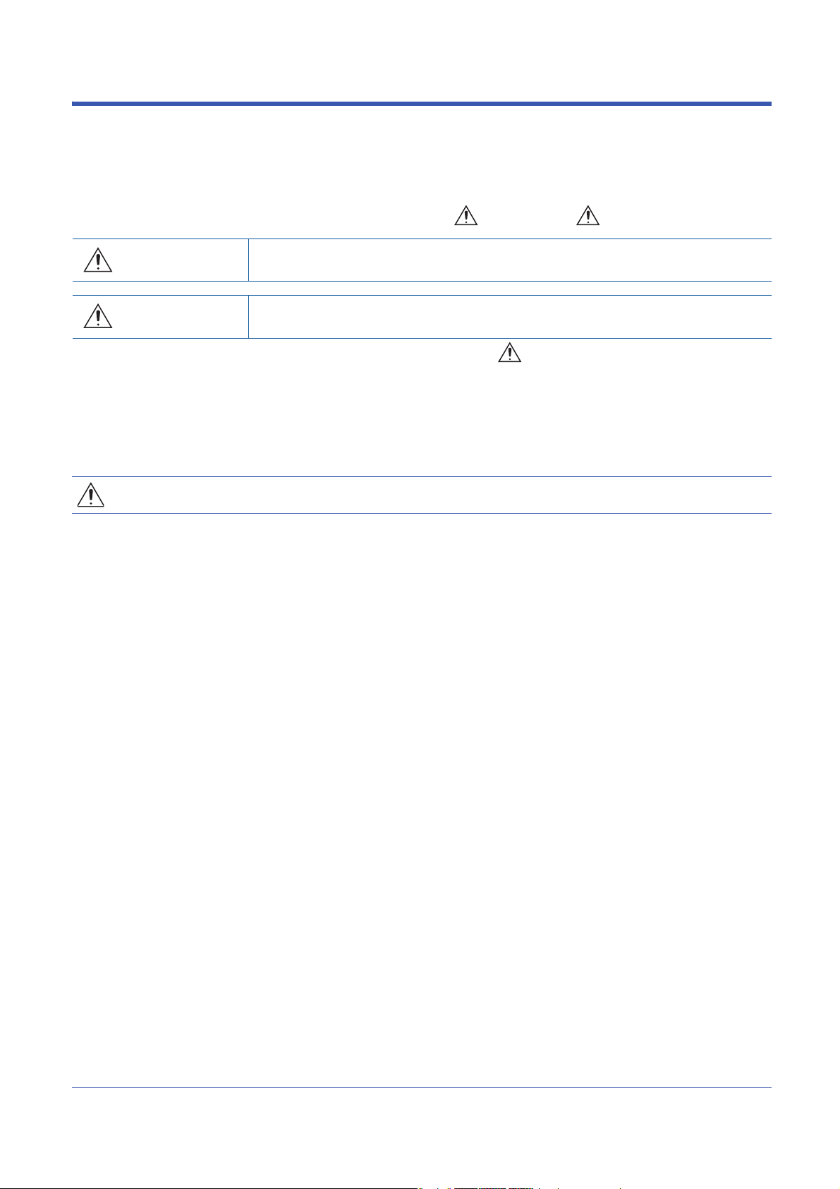
Page 22

5. Double-click the icon set in step 4, and open the
detailed setting window.
6. Select "Connection via HUB" for the connection method,
and enter the station number and IP address or host
name for the Ethernet-equipped module. Select
"RJ71EN71" to connect the RnENCPU (network part).
7. Set "Other Station Setting" or "Network Communication
*1 The network number and station number do not need to be set when connecting with the CPU module (built-in Ethernet port part).
Route" if necessary.
20
1 FUNCTIONS
1.1 Connection with MELSOFT Product and GOT
Page 23
Searching modules on the network
When connecting with a hub, a list of modules that can be searched for will appear by clicking the [Find] button on the detailed
setting window.
1
■Search target modules
• The control CPU of the RJ71EN71 or the CPU module connected to the same hub as the engineering tool
• The control CPU of the RJ71EN71 or the CPU module connected to cascade-connected hub
• The remote head module that controls the RJ71EN71 connected to the same hub as the engineering tool
• The remote head module that controls the RJ71EN71 connected to a cascade-connected hub
• By setting "Do Not Respond to CPU Module Search" in "Security" under "Application Settings" to "Do Not
Respond", the modules will not be listed even if a search is performed.
• Only the MELSEC iQ-R Series Ethernet-equipped modules are searched.
• The RJ71EN71 in which the network type is set to "Q Compatible Ethernet" cannot be searched.
1 FUNCTIONS
1.1 Connection with MELSOFT Product and GOT
21
Page 24

■When module does not appear after search
If a connected Ethernet-equipped module does not appear in the list after searching the modules on the network, check the
following items.
• Search cannot be performed if it is disabled with the IP filter function.
• Modules connected via a router cannot be searched.
• If the module is connected via a wireless LAN, packet loss can prevent the Ethernet communication from stabilizing, and
may inhibit the module search.
• If there are modules with the same IP address in the list, review the IP address parameter settings for the Ethernetequipped module.
• If the service processing load of the search-target CPU module is high, it may not be possible to search for the
corresponding module. If the search cannot be performed, increase the response wait time in the search dialog, and
perform the search again.
Precautions
■Remote operation
If remote STOP or remote PAUSE has been executed from the engineering tool to the CPU module on another station when
the CPU module (built-in Ethernet port part) and engineering tool are connected with an Ethernet cable, perform the following
before turning the power off or resetting the CPU module.
• Remote RUN
• Remote RESET
■Functions incompatible with connection via a hub
The following functions cannot be used for connection via a hub. To use the following functions, connect the CPU module
(built-in Ethernet port part) directly or with a USB cable.
• Ethernet Diagnostics
• CC-Link IE Field Diagnostics
• CC-Link IE Control Diagnostics
22
1 FUNCTIONS
1.1 Connection with MELSOFT Product and GOT
Page 25
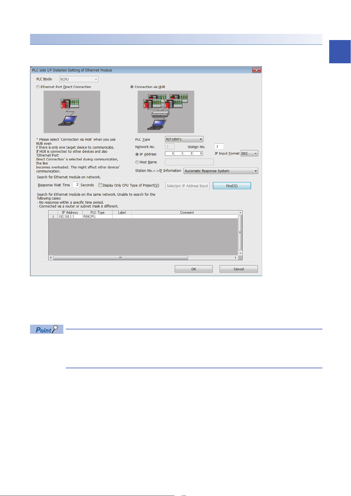
■Communications by network number/station number by using the CPU module (built-in
USB
(1)
Ethernet Ethernet
USB
(2)(3)
Ethernet module controlled by CPU No.2
Ethernet Ethernet
Ethernet port part)
• The UDP/IP protocol is used for the connection and data is always exchanged as binary codes.
• When accessing another station, set the network number for the CPU module (built-in Ethernet port part) so that it is unique
among the network numbers of the other network. Also, set the station number that is unique among the station numbers
set for the other modules on the same network.
• When configuring the target station or relay station as a multiple CPU system, ensure that the CPU modules listed below
have the firmware supporting the communications by network number/station number.
• Target station
• CPU modules working as the relay path
• CPU module that controls the Ethernet module working as the relay path
When communicating with CPU module shown as (1), ensure that all CPU modules have the firmware of the version supporting the communications by network
number/station number. Also, set the network number and station number to all CPU modules.
1
When communicating with CPU module shown as (2), ensure also that all CPU modules have the firmware of the version supporting the communications by
network number/station number. Note, however, that the communication is possible even when the network number and station number are not set to CPU
module shown as (3) of the CPU No. 2.
1 FUNCTIONS
1.1 Connection with MELSOFT Product and GOT
23
Page 26

Direct connection
The Ethernet-equipped module and engineering tool can be directly connected with one Ethernet cable without using a hub.
When direct connection is made, communication is possible without setting the IP address or host name in the "Specify
Connection Destination Connection" window. (Communicate using broadcast communications)
• To prohibit direct connection with the Ethernet, set "Disable" for "Disable Direct Connection with MELSOFT"
in "Security" under the "Application Settings".
• A direct connection is not possible when the RJ71EN71 network type is set to "Q Compatible Ethernet".
Set in the "Specify Connection Destination Connection" window.
[Online] [Current Connection Destination]
24
1. Set "PC side I/F" to "Ethernet Board".
2. Double-click "Ethernet Board", and open the "PC side I/
F Detailed Setting of Ethernet Board" window.
3. Set the network number, station number, and protocol of
the personal computer. (Set the network number and
protocol according to the settings for the Ethernetequipped module. Set the station number so that it is not
the same as a station number assigned to other
Ethernet devices.)
4. Set the "PLC side I/F" to the module to be connected.
1 FUNCTIONS
1.1 Connection with MELSOFT Product and GOT
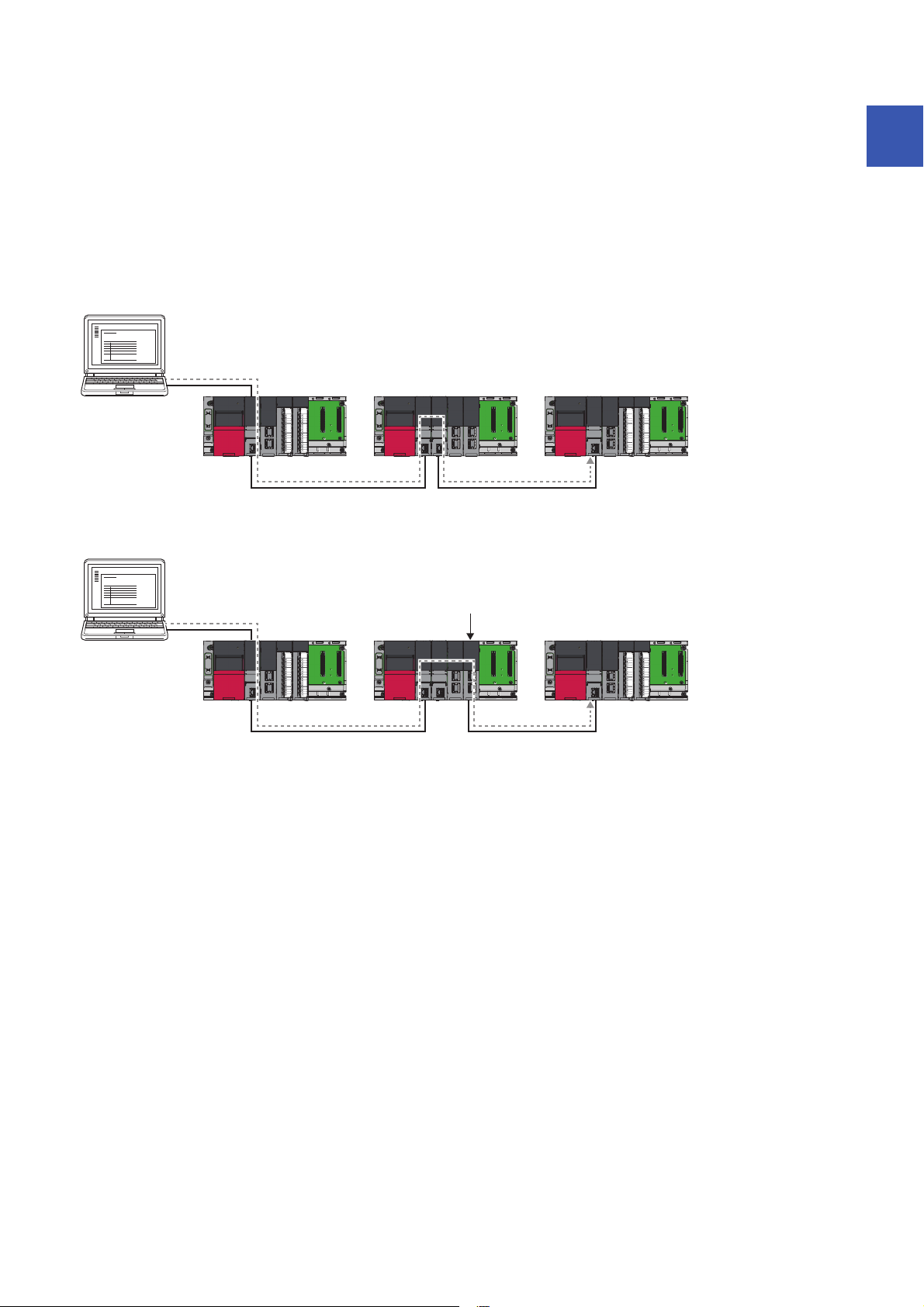
Page 27
5. Double-click the icon set in step 4, and open the
detailed setting window.
6. Select "Ethernet Port Direct Connection" for the
connection method.
When connecting directly with the CPU module (built-in Ethernet port part), setting is also possible by clicking
the [CPU Module Direct Coupled Setting] button of the "Specify Connection Destination Connection" window.
1
Precautions
■Connection with LAN line
Do not connect with a LAN line and set direct connection. Data will be sent to all external devices on the LAN line, so this
setting will cause the line load to increase and will affect communication with other external devices.
■Connections that are not direct connections
• Do not use a configuration in which the Ethernet-equipped module and external device are connected with a hub. A direct
connection is not established when the devices are connected with a hub.
• When creating a network connection on the personal computer side, communication with a direct connection is not possible
if two or more Ethernet ports are set to "Enable". Review the personal computer settings so that only the Ethernet port for
the direct connection is set to "Enable", and the other Ethernet ports are set to "Disable".
■Settings incompatible with direct connection
When using the RJ71EN71 or the RnENCPU (network part), a direct connection cannot be established if the following setting
is made in the "Specify Connection Destination Connection" window of the engineering tool.
• When "Other Station (Co-existence Network)" is selected for "Other Station Setting"
• When "Other Station (Single Network)" is selected for "Other Station Setting", and "Other station in the same loop or access
to multilevel system" is selected in the "Network Communication Route Detailed Setting of Ethernet" window
■Functions incompatible with direct connection
The following functions cannot be used when the RJ71EN71 or the RnENCPU (network part) is directly connected. To use the
following functions, connect the CPU module (built-in Ethernet port part) directly or connect the CPU module with a USB
cable.
• CC-Link IE Field Diagnostics
• CC-Link IE Control Diagnostics
1 FUNCTIONS
1.1 Connection with MELSOFT Product and GOT
25
Page 28

■Conditions that cannot communicate with direct connection
Ex.
Ex.
Communication with a direct connection may be disabled if the following conditions apply. If connection is not possible, review
the settings for the Ethernet-equipped module and personal computer.
• When all bits of the IP address for the Ethernet-equipped module that correspond with the 0 section of the subnet mask for
the personal computer are on or off
IP address for the Ethernet-equipped module: 64.64.255.255
IP address for the personal computer: 64.64.1.1
Subnet mask for the personal computer: 255.255.0.0
• When all bits of the IP address for the Ethernet-equipped module that correspond with the host address of each class in the
IP address for the personal computer are on or off
IP address for the personal computer: 192.168.0.1 192.x.x.x., class C and the host address is the fourth octet.
Subnet mask for the personal computer: 255.0.0.0
IP address for the Ethernet-equipped module: 64.64.255.255 each bit turns on because of the fourth octet is 255
The IP address for each class are as follow.
• Class A: 0.x.x.x to 127.x.x.x
• Class B: 128.x.x.x to 191.x.x.x
• Class C: 192.x.x.x to 223.x.x.x
The host address for each class is the 0 section shown below.
• Class A: 255.0.0.0
• Class B: 255.255.0.0
• Class C: 255.255.255.0
26
1 FUNCTIONS
1.1 Connection with MELSOFT Product and GOT
Page 29

1.2 SLMP Communications
SLMP is a protocol used by external devices to access SLMP-compatible devices via the Ethernet.
SLMP communications are available among devices that can receive/send messages with the SLMP control procedure.
The Ethernet-equipped module processes and transfers data following instructions (command) from the external device, so
the programmable controller only needs the open/close processing and does not require a program for data communication.
For SLMP communications, refer to the following.
SLMP Reference Manual
Applications
This section describes the applications of SLMP communications.
Data read/write
Data read/write can be executed for the following data. With this, the external device can monitor the operation of the
Ethernet-equipped module, analyze data, and control production.
• Device or global label of the CPU module connected with the RJ71EN71 (When the Ethernet function of the RJ71EN71 or
the RnENCPU (network part) is used)
• Device or global label of the CPU module (When the Ethernet function of the CPU module (CPU part for the RnENCPU) is
used)
• Buffer memory of the intelligent function module
1
File read/write
Files such as parameter files stored in a CPU module can be read/written. Files in a CPU module can be managed on an
external device.
Remote control of a CPU module
A CPU module can be remotely controlled from the external device using remote operations.
Remote password lock/unlock
The remote password can be locked and unlocked from the external device.
Access to the programmable controller on another station via other network
In systems with CC-Link IE Controller Network, CC-Link IE Field Network, MELSECNET/H, MELSECNET/10 or Ethernet, the
programmable controller on another station can be accessed from the external device via the network. However, when
connecting the external device to the CPU module (built-in Ethernet port part), other stations cannot be accessed via network
such as CC-Link IE Controller Network and CC-Link IE Field Network.
Accessing to another station via the port 1 and port 2 of the RJ71EN71 is possible for the module with the
firmware version of "18" or later.
1 FUNCTIONS
1.2 SLMP Communications
27
Page 30
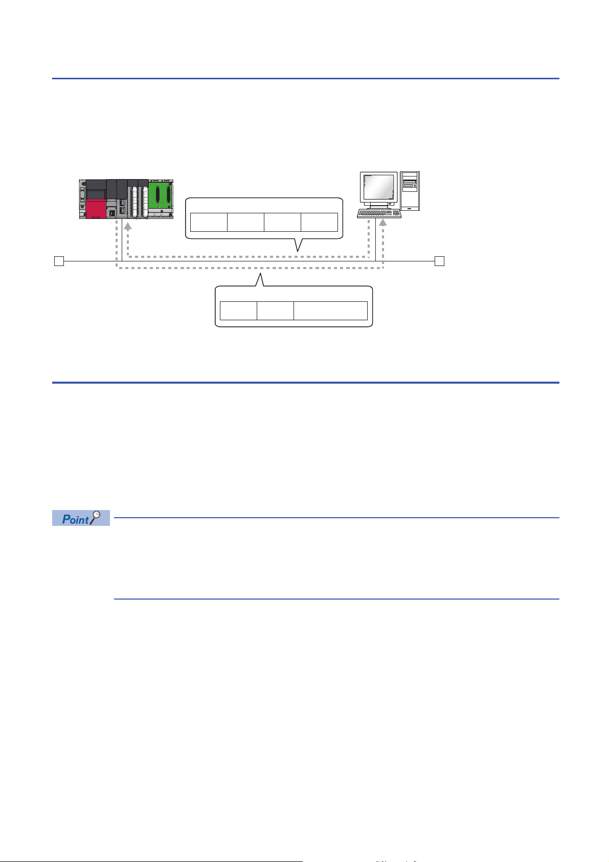
Communication structure
(1)
(2)
Ethernet
Header Command
Access
destination
Request message
Subheader
Header Response dataSubheader
Response message
When a message is sent from the external device to the Ethernet-equipped module using the SLMP message format, the
Ethernet-equipped module executes a processing corresponding to the received message. During communication, the
Ethernet-equipped module functions as a server and the external device (terminals such as a personal computer) functions as
the client. The server (Ethernet-equipped module) automatically returns a response message suitable for the request
message received from the client.
(1) Server side: Ethernet-equipped module
(2) Client side: External device
Data communication procedures
This section describes the procedures for communicating with SLMP.
1. After the module parameters are set, the system checks that the initial processing of the Ethernet-equipped module has
ended normally. ('Initial status' (Un\G1900024.0): On)
2. Perform the open processing to establish a connection between the Ethernet-equipped module and external device.
( Page 378 TCP/IP Communications, UDP/IP Communications)
3. After the connection is established, the SLMP messages are sent from the external device.
4. Close the connection when communication is finished.
In the following case, the Ethernet-equipped module performs a remote password check when the external
device is accessing the programmable controller. If communication is not possible, unlock the remote
password. ( Page 177 Access permit processing (Unlock processing))
• When remote password is set for the CPU module.
• When connection for exchanging data with external device is set as a remote password check target.
28
1 FUNCTIONS
1.2 SLMP Communications
Page 31

Setting procedure
Set "External Device Configuration" under "Basic Settings". ( Page 244 External Device Configuration)
1. Select "SLMP Connection Module" in "Module List" and drag it to "List of devices" or "Device map area".
2. Set the other items to the connection if required.
Communications using an auto-open UDP port
The auto-open UDP port is used for communication with SLMP.
The auto-open UDP port is a UDP/IP port that automatically opens and closes at the following timing. When this port is used,
communication is enabled when the initial processing is completed. Communication can be performed without a program
regardless of the connection's open status.
■Open/close timing
After the Ethernet-equipped module initial processing completes, the port automatically opens according to the registered
parameter settings. The port automatically closes when the power for the Ethernet-equipped module station turns off or is
reset.
• When the initial processing ends normally, the Ethernet-equipped module enables communications using
an automatic open UDP port. The module waits for a communication request to the Ethernet-equipped
module on the own station. (Automatic open)
• The Ethernet-equipped module accepts and processes requests from anywhere as long as they are
addressed to the Ethernet-equipped module itself.
• If a communication request is received from an external device, the corresponding port number is occupied
until that processing ends. Even if another communication request is accepted during this time, the
communication processing will be waited.
1
1 FUNCTIONS
1.2 SLMP Communications
29
Page 32

List of valid commands
The following table lists the commands that can be executed from the external device to the Ethernet-equipped module.
"" in the "Sub-command" field differs according to the specified device.
For details on each command, refer to the following.
SLMP Reference Manual
Item Command Sub
Typ e Operation
Device Read 0401 001 Reads value from the bit devices (consecutive device No.) in one-point units.
Write 1401 001 Writes value to the bit devices (consecutive device No.) in one-point units.
Read Random 0403 000 Specifies the device number and reads value from the word devices in one-word units
Write Random 1402 001 Specifies the device No. to bit device in one-point units and writes value. This can be
Entry Monitor
Device
Execute Monitor 0802 0000 Reads the value of device registered by Entry Monitor Device (command: 0801).
Read Block 0406 000 Reads data by treating n points of word devices or bit devices (one point is equivalent
Write Block 1406 000 Writes data by treating n points of word devices or bit devices (one point is equivalent
Label Array Label Read 041A 0000 Reads data from array type labels or labels whose structure members are the array.
Array Label Write 141A 0000 Writes data to array type labels or labels whose and structure members are the array.
Read Random 041C 0000 Specifies labels and reads the data.
Write Random 141B 0000 Specifies labels and writes data.
Memory Read 0613 0000 Reads the buffer memory data of own station (SLMP-compatible device).
Write 1613 0000 Writes the data in the buffer memory of own station (SLMP-compatible device).
Extend Unit Read 0601 0000 Reads the data in the buffer memory of intelligent function module.
Write 1601 0000 Writes the data in the buffer memory of intelligent function module.
0801 000 Registers the device to be read by Execute Monitor (command: 0802).
command
000 • Reads values from the bit device (consecutive device No.) in 16-point units.
003 Reads value from the bit devices (consecutive device No.) in one-point units.
002 • Reads values from the bit device (consecutive device No.) in 16-point units.
000 • Writes value to the bit devices (consecutive device No.) in 16-point units.
003 Writes value to the bit devices (consecutive device No.) in one-point units.
002 • Writes value to the bit devices (consecutive device No.) in 16-point units.
002 Specifies the device number and reads value from the word devices in one-word units
000 • Specifies the device No. to bit device in 16-point units and writes value. This can be
003 Specifies the device No. to bit device in one-point units and writes value. This can be
002 • Specifies the device No. to bit device in 16-point units and writes value. This can be
002
002
002
Description
• Reads value from the word devices (consecutive device No.) in one-word units.
• Reads value from the word devices (consecutive device No.) in one-word units.
• Writes value to the word devices (consecutive device No.) in one-word units.
• Writes value to the word devices (consecutive device No.) in one-word units.
or two-word units. This can be specified with inconsecutive device No.
or two-word units. This can be specified with inconsecutive device No.
specified with inconsecutive device No.
specified with inconsecutive device No.
• Specifies the device No. to word device in one-word units or two-word units and
writes value. This can be specified with inconsecutive device No.
specified with inconsecutive device No.
specified with inconsecutive device No.
• Specifies the device No. to word device in one-word units or two-word units and
writes value. This can be specified with inconsecutive device No.
to 16 bits) as one block and specifying multiple blocks. This can be specified with
inconsecutive device No.
to 16 bits) as one block and specifying multiple blocks. This can be specified with
inconsecutive device No.
30
1 FUNCTIONS
1.2 SLMP Communications
Page 33

Item Command Sub
Typ e Operation
Remote Control Remote Run 1001 0000 Executes the remote RUN to the access destination module.
Remote Stop 1002 0000 Executes the remote STOP to the access destination module.
Remote Pause 1003 0000 Executes the remote PAUSE to the access destination module.
Remote Latch
Clear
Remote Reset 1006 0000 Executes the Remote RESET to the access destination module.
Read Type Name 0101 0000 Reads the model name and model code of the access destination module.
Remote
Password
File Read Directory/
Self Test 0619 0000 Tests whether the communication with external devices is normally executed or not.
Lock 1631 0000 Specifies the remote password to disable the communication with other devices.
Unlock 1630 0000 Specifies the remote password to enable communication with other devices.
File
Search Directory/
File
New File 1820 0040 Reserves storage area for the specified file.
Delete File 1822 0040 Deletes a file.
Copy File 1824 0040 Copies the specified file.
Change File
State
Change File Date 1826 0040 Changes the file creation date.
Open File 1827 0040 Locks a file so that the content of the file is not changed by other devices.
Read File 1828 0000 Reads the data of a file.
Write File 1829 0000 Writes the contents in a file.
Close File 182A 0000 Cancels the file lock by open processing.
1005 0000 Executes the Remote Latch Clear to the access destination module.
1810 0040 Reads file list information.
1811 0040 Reads the presence of the specified file, file No., and file size.
1825 0040 Changes file attributes.
command
Description
(The locked state is activated from the unlocked state.)
(The unlocked state is activated from the locked state.)
1
1 FUNCTIONS
1.2 SLMP Communications
31
Page 34

1.3 Communications Using the Predefined Protocol
Ò
Ô
Ó
GX Works3
Setting protocols Writing protocols
Executing protocols
Data can be communicated
with protocols appropriate
to each external device.
External device External device
Ethernet-equipped module
Sending
Receiving
Execute protocols by dedicated instructions.
Multiple protocols can be executed by one dedicated instruction.
Write the set protocols in the Ethernet-equipped module. Protocols can be set easily using the predefined
protocol support function of GX Works3.
Data can be exchanged between the external device (such as measuring instrument and bar code reader) and the CPU
module following the protocol of the device.
Data that varies according to communication session can be handled by incorporating a device or buffer memory into the
communication packet.
Sets the protocol required for communication with the external device using the engineering tool.
The protocol can be set by selecting from the predefined protocol library, or it can be created and edited.
The number of protocols and packets that can be registered is as follow.
• Protocols: 128 maximum
• Packets: 256 maximum
• Packet data area size: 12288 bytes maximum
When the number of packets reaches the upper limit, protocols cannot be added even if the number of
protocols has not reached the upper limit. If the packet data area size reaches the upper limit, protocols and
packets cannot be added even if the number of protocols and packets has not reached the upper limit.
Applicable connections
The connections No.1 to 16 of the P1 connector can be used for the communications using the predefined protocol.
Communications using the predefined protocol cannot be used with the P2 connector.
32
1 FUNCTIONS
1.3 Communications Using the Predefined Protocol
Page 35

Data communication procedures
When the predefined protocol support function is used, data can be exchanged with the external device using the following
procedure.
1. Select, create or edit the protocol with the predefined protocol support function, and write the protocol setting data. (
Page 33 Creating the protocol setting data)
2. Set the module parameter. ( Page 39 Setting procedure)
3. Write the parameters to the CPU module, and check that initial processing of the Ethernet-equipped module completed
successfully. ('Initial status' (Un\G1900024.0): On)
4. Perform the open processing to establish a connection between the Ethernet-equipped module and external device.
( Page 378 TCP/IP Communications, UDP/IP Communications)
5. Execute the protocol with the dedicated instruction (SP.ECPRTCL instruction or GP.ECPRTCL instruction).
6. Close the connection when communication is finished.
The communication data code is binary code communication regardless of the selected settings.
Creating the protocol setting data
Use the predefined protocol support function to create the protocol setting data.
[Tool] [Predefined Protocol Support Function]
1. Select the module for which to create the protocol
setting data. Select the following items when using the
RnENCPU.
• CPU part: "Built-in Ethernet CPU"
• Network part: "Ethernet Module"
1
1 FUNCTIONS
1.3 Communications Using the Predefined Protocol
33
Page 36

■Newly creating the protocol setting data
Newly create the protocol setting data.
[File] [New]
Item Description
Protocol No. Displays the protocol number used with the dedicated instruction in the program.
Manufacturer Displays the name of the manufacturer of the device for which the protocol is being set.
Model Displays the model of the protocol to be set.
Protocol Name Displays the name of the protocol to be set.
Communication Type Displays the communication type of the protocol to be set.
Send/Receive Displays the packet send direction.
Packet Name Displays the packet name.
Packet Setting Displays the validity of variables in the packet elements and the variable setting state.
Send only: Sends one send packet once.
Receive only: If there is a matching packet within up to 16 registered and received packets, it is received.
Send & receive: After sending one send packet, if there is a matching packet within up to 16 registered and received
packets, it is received.
: For send
(1) to (16): For receive, the received packet number is displayed in parentheses.
If the variable is not set, there are no elements, or there is an element error, the protocol is not written to the Ethernetequipped module.
No Variable: When there is no variable in the elements
Variable Set: Only when all variables have been set
Variable Unset: When there is even one unset variable
Element Unset: When there are no elements in an editable protocol
Element error: When elements do not satisfy requirements
34
1 FUNCTIONS
1.3 Communications Using the Predefined Protocol
Page 37

■Adding protocol
Add protocol.
[Edit] [Add Protocol]
Item Description Setting range
Type Select the type of protocol to be added. • Predefined Protocol Library
• User Protocol Library
• Add New
Protocol No. Select the protocol number to be added. 1 to 128
Manufacturer
Model
Protocol Name
*1 The name can be set only when "Predefined Protocol Library" is selected for "Type".
*1
*1
*1
Set the maker of the protocol to be added.
Set the type of protocol to be added.
Set the name of the protocol to be added.
1
1 FUNCTIONS
1.3 Communications Using the Predefined Protocol
35
Page 38

■Protocol Detailed Setting
Set the protocol send/receive parameters.
"Protocol Setting" window Select a protocol [Edit] [Protocol Detailed Setting]
Item Description
Connected Device
Information
Protocol Setting
Information
Receive Setting Receive Wait Time Set the time for wait after the module enters the receive data wait state.
Send Setting Standby Time Set the time to wait from when the protocol set for the module enters the execution state to when the
*1
*1
Manufacturer Set the protocol maker name.
Type Set the protocol device type.
Model Set the protocol model.
Version Set the protocol device version.
Description Set a description of the protocol device.
Protocol No. The protocol number for the selected protocol is displayed.
Protocol Name Set the protocol name.
Communication Type Set the protocol communication type.
If communication with the external device is disabled because of a disconnection and matching packet
data is not received within the specified time, the module judges that an error has occurred and cancels
the receive data wait state.
data is actually sent. The time for the external device to enter the receive enable state can be adjusted
with this in respect to the module's send timing.
*1 The setting cannot be changed if the protocol was selected from the predefined protocol library.
Send/receive parameters can be set for multiple protocols by clicking the [Communication Parameter Batch
Setting] button and setting the range of the set protocol numbers, receive settings, and send settings.
36
1 FUNCTIONS
1.3 Communications Using the Predefined Protocol
Page 39

■Packet setting
Set the configuration of the send/receive packets on the "Packet Setting" window.
"Protocol Setting" window Packet to be set
1
The above window opens when "Predefined Protocol Library" is selected on the "Add Protocol" window.
When "Add New" or "User Protocol Library" has been selected, configure the packets with the [Change Type] button and [Add
New] button.
For details on the packet elements, refer to the following.
Page 41 Packet elements
■Writing the protocol setting data
Write the protocol setting data to the Ethernet-equipped module.
[Online] [Write to Module]
Select the module and memory into which the protocol data is to be written, and execute write.
When writing to a CPU module, the protocol setting data is written into the module extension parameters.
1.3 Communications Using the Predefined Protocol
1 FUNCTIONS
37
Page 40

The following data is not written as the protocol setting data so it will not be displayed even when read.
However, when the protocol is selected from the predefined protocol library, the following can be displayed.
• Manufacturer
•Packet Name
• Protocol Detailed Setting Type, Version, Explanation
• Packet Setting Configuration Element Name
After writing the protocol setting data, the setting data are enabled at the following timing.
• When the system is powered off and on
• When the CPU module is reset
• When the status of the CPU module changed from STOP to RUN state
The predefined protocol settings written in the SD memory card can be transferred to the CPU module memory by using boot
operation. For details on boot operation, refer to the following.
MELSEC iQ-R CPU Module User's Manual (Application)
■When the protocol setting data are written into multiple target memories
When the protocol setting data are written into multiple target memories, the following operation will take place.
: The protocol setting data are written., : The predefined protocol data are not written.
Target memory Operation
CPU module (built-in
Ethernet port part)
Operation follows settings in "Module Extended Parameter" under
As soon as the protocol setting data are enabled, the predefined protocol
Operation follows settings in "Module Extended Parameter" under
SD memory card RJ71EN71,
RnENCPU (network
part)
"Setting of File/Data Use or Not in Memory Card" of the "Memory Card
Parameter" window.
settings of the RJ71EN71 or the RnENCPU (network part) are
overwritten by the predefined protocol settings in the CPU module or SD
memory card.
"Setting of File/Data Use or Not in Memory Card" of the "Memory Card
Parameter" window.
As soon as the protocol setting data are enabled, the predefined protocol
settings of the RJ71EN71 or the RnENCPU (network part) are
overwritten by the predefined protocol settings in the CPU module or SD
memory card.
38
By writing the protocol setting data to the CPU built-in memory, the same setting can be used even after
module change.
When capacity of the CPU built-in memory is insufficient, write data to an SD memory card.
Although the protocol setting data can also be written to the intelligent function module, the data must be
written again when the module is changed.
1 FUNCTIONS
1.3 Communications Using the Predefined Protocol
Page 41

Setting procedure
Set "External Device Configuration" under "Basic Settings". ( Page 244 External Device Configuration)
1. Select the external device to be connected in "Module List" and drag it to "List of devices" or "Device map area".
External device name Description
UDP Connection Module Select to communicate with the external device using UDP/IP
Active Connection Module Select to perform the open processing to the external device from the Ethernet-equipped module (Active open)
Unpassive Connection Module Select to receive the open processing from an unspecified external device (Unpassive open) and communicate
Fullpassive Connection Module Select to receive the open processing from the specified external device (Fullpassive open) and communicate
and communicate using TCP/IP.
using TCP/IP.
using TCP/IP.
2. Set "Communication Method" for the external device to "Predefined Protocol".
3. Set the other parameters required for communication in the connection.
Applicable dedicated instructions
The dedicated instructions used for communications using the predefined protocol are shown below.
: Usable, : Not usable
Instruction Description Availability
RJ71EN71, RnENCPU
(network part)
GP.ECPRTCL Executes the protocol registered with the predefined
SP.ECPRTCL
SP.SOCCINF
SP.SOCCSET
protocol support function of the engineering tool.
*1
Reads connection information
*1
Changes the communication target
CPU module (CPU part for the
RnENCPU)
*2
*2
1
*1 These instructions are the same as the instruction for the socket communications (SP.SOCCINF/SP.SOCCSET). ( MELSEC iQ-R
Programming Manual (CPU Module Instructions, Standard Functions/Function Blocks)
*2 Only the following models can be used. The supporting firmware version differs depending on the model.
R00CPU, R01CPU, R02CPU: There are no restrictions on the version.
Programmable controller CPUs other than the above: "29" or later
1 FUNCTIONS
1.3 Communications Using the Predefined Protocol
39
Page 42

Protocol communication type
Maximum data length: 2046 bytesHeader
Ethernet header TCP/IP header
Destination
MAC address:
6 bytes
Sender's MAC
address:
6 bytes
Type:
2 bytes
IP:
20 bytes
TCP:
20 bytes
Data
Maximum data length: 2046 bytesHeader
Ethernet header UDP/IP header
Destination
MAC address:
6 bytes
Sender's
MAC address:
6 bytes
Type:
2 bytes
IP:
20 bytes
UDP:
8 bytes
Data
The packets sent to the external device when a processing is executed and the external device's receive packets are
registered in the protocol.
The packet elements set with the predefined protocol support function are the data section of the packets that are actually
sent and received.
This section describes an example of the packet configuration. For details on the packet elements, refer to the following.
Page 395 Operation Image and Data Structure of Predefined Protocol
For TCP/IP
■Precautions for Passive open
• When the CPU module is connected to external device in Passive open state, the IP address of the connected external
device or port number of the external device can be obtained with the SP.SOCCINF instruction.
For UDP/IP
With the predefined protocol support function, data is exchanged with the external device with the procedures (communication
type) shown below.
For details on the communication type operation, refer to the following.
Page 395 Operation Image and Data Structure of Predefined Protocol
Communication type Description
Send only The send packet is sent once.
Receive only If there is a packet that matches within the maximum of 16 registered receive packets, the packet is received.
Send & receive After sending the send packets, if there are packets that match the up to 16 registered receive packets, the packets are
received.
■Precautions for UDP/IP communications
• Use the SP.SOCCSET instruction to change the external device by the CPU module.
■Precautions for broadcast communications
• When the CPU module receives data by receiving the broadcast, the IP address of the external device which send data and
port number of the external device can be obtained with the SP.SOCCINF instruction.
40
1 FUNCTIONS
1.3 Communications Using the Predefined Protocol
Page 43

Packet elements
The packet is created with a combination of packet elements.
Up to 32 elements can be set in one packet. One packet can have a maximum data length of 2046.
This section describes the details of the packet elements.
For examples of the packet element data, refer to the following.
Page 395 Operation Image and Data Structure of Predefined Protocol
Static data
Use when there are specific codes and character strings, such as commands, in the packet.
• When sending: The specified code and character string are sent.
• When receiving: The received data is verified.
Multiple static data elements can be placed anywhere in the data part.
The following table lists the items.
Item Description Remarks
Element Name Set the element name.
Code Type Select a data type of the setting value.
ASCII String/ASCII Control Code/HEX
Setting Value Set data within 1 to 50 bytes.
Code type and setting range are as follows:
• ASCII String: 20H to 7EH
• ASCII Control Code: Control code of 00H to 1FH and 7FH
• HEX: Hexadecimal data of 00H to FFH
Setting example
ASCII string: "ABC"
ASCII control code: STX
HEX: FFFF
1
1 FUNCTIONS
1.3 Communications Using the Predefined Protocol
41
Page 44

Length
The length code is used when there is an element that indicates the data length in the packet.
• When sending: Automatically calculates the data length in the specified range, and adds it to the packet.
• When receiving: From the received data, the data (value) corresponding to the length is verified as the specified range's
data length.
Length elements can be placed anywhere in the data part.
Multiple length elements can be set placed in one packet.
The following table lists the items.
Item Description Remarks
Element Name Set the element name.
Code Type Select the data length type.
ASCII Hexadecimal/HEX
Data Length Select the data length on the line.
The range is 1 to 4 bytes.
Data Flow Forward Direction
Calculating
Range
(Upper Byte Lower Byte)
Reverse Direction
(Lower Byte Upper Byte)
Byte Swap (by Word)
Start Select the start packet element number for the range to be calculated.
The range is 1 to 32.
End Select the end packet element number for the range to be calculated.
The range is 1 to 32.
*1
When sending: Sends the calculated length in order from the
upper byte.
When receiving: Receives the data in order from the upper byte.
When sending: Sends the calculated length in order from the loworder byte.
When receiving: Receives the data in order from the low-order
byte.
When sending: Interchanges the bytes in word units and sends the
calculated length.
When receiving: Interchanges the bytes in word units and receives
the data.
This cannot be set if the data
length is 1 byte.
*1 This can be selected only when the data length is set to 4 bytes.
1 FUNCTIONS
42
1.3 Communications Using the Predefined Protocol
Page 45

• If there are no elements other than length, an element error occurs. (When using length, one or more
elements other than length are required.)
• If the calculation result exceeds the number of digits set with "Data Length", the excessive digit value is
discarded (invalidated). For example, if the data length is 2 bytes and the data size calculation results are
"123" bytes, the data length will be "23".
• If there is a non-conversion variable (variable length)/non-verified reception (character length variable) after
the length, and that section is not included in the length calculating range, arrange the static data
immediately after the non-conversion variable/non-verified reception.
• When the code type setting is "ASCII Hexadecimal", a mismatch will occur if a character string other than
"0" to "9", "A" to "F", and "a" to "f" is received.
• Use "0" to "9" or "A" to "F" when converting to ASCII characters during send.
• When arranging multiple length elements, none of the length calculating range may overlap.
• When arranging multiple length elements, the previous length calculating range may not exceed the
arranged length.
• A length element cannot be arranged at the final position of the packet elements.
1
1 FUNCTIONS
1.3 Communications Using the Predefined Protocol
43
Page 46

Non-conversion variable
Use this to send the CPU module device or buffer memory data as part of the send packet, or to store part of the received
packet in the CPU module device or buffer memory.
Multiple non-conversion variable can be arranged in one packet.
The following table lists the items.
Item Description
Element Name Set the element name.
Fixed Length/Variable
Length
Data Length/Maximum
Data Length
Unit of Stored Data Lower Byte + Upper Byte When sending: Each one word (2 bytes) data in the data storage area is sent in the order of the lower
Byte Swap Disable (Lower
Fixed Length The data whose length is fixed is sent and received.
Variable Length When sending: The data length is specified at the time of the protocol execution and the data is sent.
Set the data length of the send/receive data.
(For a variable length, set the maximum data length that can be specified for the data length storage area.)
The range is 1 to 2046.
Lower Bytes Only When sending: Each lower byte data in the data storage area is sent. The Ethernet-equipped module
Upper)/Enable (Upper
Lower)
When receiving: The data whose length is variable is received.
byte to the upper byte.
When receiving: The receive data is stored to the data storage area in the order of the lower byte to the
upper byte.
ignores the upper byte data.
When receiving: The receive data is stored to each lower byte in the data storage area. The Ethernetequipped module stores 00H in the upper byte.
When sending:
When "Enable (Upper Lower)" is selected, data in the upper byte and lower byte are swapped by
one word (2 bytes) and sent. When "Unit of Stored Data" is "Lower Byte + Upper Byte" and "Data
Length" is an odd number of bytes, the upper byte is sent at transmission of the last byte. When "Unit
of Stored Data" is "Lower Bytes Only" and "Data Length" is an odd number of bytes, data without any
byte swap is sent at transmission of the last byte.
When receiving:
When "Enable (Upper Lower)" is selected, data in the upper byte and lower byte are swapped by
word and sent. When "Unit of Stored Data" is "Lower Byte + Upper Byte" and "Data Length" is an odd
number of bytes, the last byte is stored to the upper byte. When "Unit of Stored Data" is "Lower Bytes
Only" and "Data Length" is an odd number of bytes, the last byte is stored without any byte swap.
44
1 FUNCTIONS
1.3 Communications Using the Predefined Protocol
Page 47

Item Description
Data Storage Area
Specification
Specify the start device for storing the variable value.
The settable devices are listed below.
Inner user
File register
Buffer Memory
*1*2
• Input (X)
•Output (Y)
• Internal relay (M)
• Latch relay (L)
• Link relay (B)
• Data register (D)
• Link register (W)
• File register (R, ZR)
• G device (G) ('Send/receive area for predefined protocol support function' (Un\G1902000 to Un\G1904047))
*2
*3
*1 Do not set local devices.
*2 Set within the device range specified with "Device/Label Memory Area Setting" in "Memory/Device Setting" of "CPU Parameter".
*3 This cannot be set if the target module is a CPU module.
1
1 FUNCTIONS
1.3 Communications Using the Predefined Protocol
45
Page 48

The following figures show the configuration of the data storage area.
Data storage area
Specified device
+ 0
+ n
(Word)
Send
packet
Data storage area
Receive
packet
Data storage area
·
Data length storage area
*1
Data storage area
Specified device
+ 1
(Word)
+ n
Send
packet
Data storage area
Receive
packet
Data storage area
+ 0
■When "Fixed Length/Variable Length" is "Fixed Length"
The area after the device number specified on the "Element Setting" window becomes the data storage area.
The occupied data storage area differs according to the "Unit of Stored Data".
• When "Lower Byte + Upper Byte" is selected, the same size as the data length is occupied. (However, when the data length
of a send packet is an odd number, the upper byte (lower byte for "Byte Swap") of the end device is not sent. When the data
length of a receive packet is an odd number, the last data is stored with one byte of 00H.)
• When "Lower Bytes Only" is selected, a size double the data length is occupied.
For send packet: Send data is stored by the program
For receive packet: Receive data is stored by the Ethernet-equipped module
■When "Fixed Length/Variable Length" is "Variable Length"
The area after the device number specified on the "Element Setting" window + 1 becomes the data storage area.
The occupied data storage area differs according to the "Unit of Stored Data".
• When "Lower Byte + Upper Byte" is selected, the same size as the data length + one word (length for the data length
storage area) are occupied. (However, when the data length of a send packet is an odd number, the upper byte (lower byte
for "Byte Swap") of the end device is not sent. When the data length of a receive packet is an odd number, the last data is
stored with one byte of 00H.)
• When "Lower Bytes Only" is selected, a size double the data length + one word (for data length storage area) is occupied.
For send packet: Send data is stored by the program
For receive packet: Receive data is stored by the Ethernet-equipped module
*1 The data length unit is byte fixed
46
1 FUNCTIONS
1.3 Communications Using the Predefined Protocol
Page 49

When "Fixed Length/Variable Length" is "Variable Length" and the configuration is set as follows, an error
occurs:
• An element other than static data is placed behind a non-conversion variable element when non-conversion
variable is out of the length calculating range or when there is no length element (except for when nonconversion variable is placed at the end of the packet elements).
• Multiple non-conversion variable elements are placed in the length calculating range, while a length element
is not placed.
• A non-conversion variable element is placed before a length element in the length calculating range.
Non-verified reception
Use this when receive data include unnecessary data.
If the receive packet contains non-verified reception, Ethernet-equipped module skims over the specified number of
characters.
Multiple non-verified reception elements can be set in one packet.
The following table lists the items.
Item Description Remarks
Element Name Set the element name.
Data Length 0 (Number of characters
variable)
1 to 2046 (number of
character specification)
Set when the number of characters that are not verified differs
between each communication session.
Set the number of characters that are not verified.
1
When "Data Length" is set to 0, an error will occur if the following layout is used.
• An element other than static data is placed behind a non-verified reception element when non-verified
reception is out of the length calculating range or when there is no length element (except for when nonverified reception is placed at the end of the packet elements).
• Multiple non-verified reception elements are placed in the length calculating range, while a length element is
not placed.
• A non-verified reception element is placed before a length element in the length calculating range.
1 FUNCTIONS
1.3 Communications Using the Predefined Protocol
47
Page 50

Execution conditions of predefined protocol communications
The predefined protocol communications can be executed when 'Predefined protocol ready' (Un\G1901002.0) is on.
This section describes the operation of 'Predefined protocol ready' (Un\G1901002.0).
When the system is powered on or reset
If protocol setting data is written in, the Ethernet-equipped module checks the protocol setting data when the system is
powered on or reset.
If the protocol setting data is normal, the Ethernet-equipped module turns on 'Predefined protocol ready' (Un\G1901002.0),
and enables execution of the protocol.
'Predefined protocol ready' (Un\G1901002.0) is used as the interlock signal for executing the protocol.
If the protocol setting data is abnormal, 'Predefined protocol ready' (Un\G1901002.0) stays off, and the details of the error are
stored in 'Predefined protocol setting data check area' (Un\G1901020 to Un\G1901047).
If protocol setting data is not written in, the protocol setting data is not checked, and 'Predefined protocol ready'
(Un\G1901002.0) remains off.
Whether the protocol setting data is registered or not can be checked with 'Number of registered predefined protocols'
(Un\G1901024) and 'Predefined protocol registration' (Un\G1901032 to Un\G1901047).
48
1 FUNCTIONS
1.3 Communications Using the Predefined Protocol
Page 51

■When protocol setting data is normal
Ethernet-equipped module
'Predefined protocol ready'
(Un\G1901002.0)
'Predefined protocol setting
data check area'
(Un\G1901020 to Un\G1901047)
Checking the protocol
setting data
Bit 0 turns on when the
check result is normal.
Power on/reset
The number of registered protocols and information
about whether protocols have been registered are stored.
Normal result
Ethernet-equipped module
'Predefined protocol ready'
(Un\G1901002.0)
'Predefined protocol setting
data check area'
(Un\G1901020 to Un\G1901047)
Checking the protocol
setting data
Power on/reset
The error details are stored.
Abnormal result
Bit 0 remains off.
■When protocol setting data is abnormal
1
When executing UINI instruction
When the RJ71EN71 network type is set to "Q Compatible Ethernet" and the UINI instruction is executed, the protocol setting
data will not be checked.
Predefined protocol ready maintains the state before the UINI instruction was executed.
1.3 Communications Using the Predefined Protocol
1 FUNCTIONS
49
Page 52

Example of predefined protocol communications
GX Works3
Sending side
(192.0.1.100)
Receiving side
(192.0.1.101)
Ethernet
This section describes an example of predefined protocol communications using UDP/IP.
System configuration
Parameter settings
Connect the engineering tool to the CPU module and set the parameters.
■Sending side
1. Set the CPU module as follows.
[Project] [New]
2. Click the [OK] button to add the module labels of the CPU module.
50
1 FUNCTIONS
1.3 Communications Using the Predefined Protocol
Page 53

3. Set the RJ71EN71 as follows.
[Navigation window] [Parameter] [Module Information] Right-click [Add New Module]
4. Click the [OK] button to add the module labels of the RJ71EN71.
1
5. Set the items in "Basic Settings" as follows.
[Navigation window] [Parameter] [Module Information] [RJ71EN71] [Port 1 Module Parameter (Ethernet)]
[Basic Settings]
1 FUNCTIONS
1.3 Communications Using the Predefined Protocol
51
Page 54

6. Set the network configuration as follows.
[Navigation window] [Parameter] [Module Information] [RJ71EN71] [Port 1 Module Parameter (Ethernet)]
[Basic Settings] [External Device Configuration]
7. Start the predefined protocol support function.
[Tool] [Predefined Protocol Support Function]
8. Select "Ethernet Module" for "Module Type" and click the [OK] button.
9. Newly create the protocol setting.
[File] [New]
52
1 FUNCTIONS
1.3 Communications Using the Predefined Protocol
Page 55

10. Set the protocol as follows.
[Edit] [Add Protocol]
11. Set each packet as follows.
"Protocol Setting" window Packet to be set
• Request
1
1 FUNCTIONS
1.3 Communications Using the Predefined Protocol
53
Page 56

• Normal response
• Error response
54
1 FUNCTIONS
1.3 Communications Using the Predefined Protocol
Page 57

12. Write the protocol setting data to the CPU module.
[Online] [Write to Module]
13. Write the set parameters to the CPU module. Then reset the CPU module or power off and on the system.
[Online] [Write to PLC]
In this example, default values were used for parameters that are not shown above. For the parameter setting,
refer to the chapter explaining the parameters in this manual. ( Page 241 PARAMETER SETTINGS)
1
■Receiving side
1. Set the CPU module and add the module labels of the CPU module. The setting method of the CPU module and addition
method of the module label are the same as those of when setting the sending side. ( Page 50 Sending side)
2. Set the RJ71EN71 and add the module labels of the RJ71EN71. The setting method of the RJ71EN71 and addition
method of the module label are the same as those of when setting the sending side. ( Page 50 Sending side)
3. Set the items in "Basic Settings" as follows.
[Navigation window] [Parameter] [Module Information] [RJ71EN71] [Port 1 Module Parameter (Ethernet)]
[Basic Settings]
1 FUNCTIONS
1.3 Communications Using the Predefined Protocol
55
Page 58

4. Set the network configuration as follows.
[Navigation window] [Parameter] [Module Information] [RJ71EN71] [Port 1 Module Parameter (Ethernet)]
[Basic Settings] [External Device Configuration]
5. Write the set parameters to the CPU module. Then reset the CPU module or power off and on the system.
[Online] [Write to PLC]
In this example, default values were used for parameters that are not shown above. For the parameter setting,
refer to the chapter explaining the parameters in this manual. ( Page 241 PARAMETER SETTINGS)
56
1 FUNCTIONS
1.3 Communications Using the Predefined Protocol
Page 59

Program examples
Classification Label name Description Device
Module label EN71_EE_1.bnCompletion_ConnectionOpen[1] Open completion signal (connection No.1) U0\G1900000.0
EN71_EE_1.uCompletion_EthernetInitialized_D.0 Initial status U0\G1900024.0
EN71_EE_1.bReady_PredefinedProtocol_D Predefined protocol ready U0\G1901002.0
Label to be defined Define global labels as shown below:
1
1 FUNCTIONS
1.3 Communications Using the Predefined Protocol
57
Page 60

(0) When 'bStart' (M0) is turned on, the protocol is executed by the GP.ECPRTCL instruction and D100 to D109 of the receiving side CPU module is read
and stored in D14 to D23 of the sending side CPU module.
'bComp_OK' (M10) is turned on when the protocol completed successfully.
D0 to D8 stores the following as a protocol setting data.
Device
number
D0 Serial No. The number increases one by one each time the 'bStart' (M0) is turned on.
D1 Network No. 0H Because the access destination is the connected station (own station), 0H is stored as the request
D2 Station No. FFH Because the access destination is the connected station (own station), FFH is stored as the
D3 Requested module I/O
D4 Monitoring timer 10H The monitoring timer is set to 4 seconds. (Unit: 250ms)
D5 to D6 Head device No. 100 To read D100 to D109, start device number is set to 100.
D7 Device code A8H To read D100 to D109, device code is set to A8H.
D8 Number of device points 10 To read 10 points from D100 to D109, number of device points is set to 10.
Element name Setting
value
3FFH Because the access destination is the receiving side CPU module (control CPU of the receiving
No.
Description
destination network number.
request destination station number.
side RJ71EN71), 3FFH is stored.
In this program example, a receiving side program is not required.
58
1 FUNCTIONS
1.3 Communications Using the Predefined Protocol
Page 61

1.4 Socket Communications
Ethernet-equipped module
External device
External device
External device
Ethernet
Receive or
broadcast receive
Send
Broadcast send
Broadcast send
Using dedicated instructions, arbitrary data can be exchanged with an external device connected by Ethernet over TCP/IP or
UDP/IP.
Use this for bidirectional communication one-on-one with an external device.
1
Precautions
Socket communications cannot be used when the RJ71EN71 network type is set to "Q Compatible Ethernet".
Setting procedure
Set "External Device Configuration" under "Basic Settings". ( Page 244 External Device Configuration)
1. Select the external device to be connected in "Module List" and drag it to "List of devices" or "Device map area".
External device name Description
UDP Connection Module Select to communicate with the external device using UDP/IP
Active Connection Module Select to perform the open processing to the external device from the Ethernet-equipped module (Active open)
Unpassive Connection Module Select to receive the open processing from an unspecified external device (Unpassive open) and communicate
Fullpassive Connection Module Select to receive the open processing from the specified external device (Fullpassive open) and communicate
2. Set "Communication Method" for the external device to "Socket Communication".
3. Set the other parameters required for communication in the connection.
For examples of socket communications, refer to the following.
MELSEC iQ-R Ethernet/CC-Link IE User's Manual (Startup)
and communicate using TCP/IP.
using TCP/IP.
using TCP/IP.
1 FUNCTIONS
1.4 Socket Communications
59
Page 62

Applicable dedicated instructions
The following table lists the dedicated instructions for exchanging data with socket communications.
For details on dedicated instructions, refer to the following.
MELSEC iQ-R Programming Manual (CPU Module Instructions, Standard Functions/Function Blocks
MELSEC iQ-R Programming Manual (Module Dedicated Instructions)
List of dedicated instructions
The following table lists the dedicated instructions used by each module.
■Instructions used by the RJ71EN71 and the RnENCPU (network part)
Instruction Description
GP.CONOPEN Establishes a connection.
GP.CONCLOSE Closes the connection.
GP.SOCRCV Reads the receive data from the external device.
G.SOCRCVS
GP.SOCSND Sends data to the external device.
■Instructions used by the CPU module (CPU part for the RnENCPU)
Instruction Description
SP.SOCOPEN Establishes a connection.
SP.SOCCLOSE Closes the connection.
SP.SOCRCV Reads the receive data from the external device.
G.SOCRCVS
S.SOCRCVS
GP.SOCSND Sends data to the external device.
SP.SOCSND
SP.SOCCINF Reads connection information
SP.SOCCSET Changes the communication target
SP.SOCRMODE Changes the connection receive mode.
S(P).SOCRDATA Reads the specified size of data from the socket communications receive data area.
If the instruction has a completion device, do not change the various data (such as control data and request
data) specified with the executed instruction until execution of the instruction is completed.
Applicable connections
The following connections can be used for data exchange with socket communications.
Module Usable connections
RJ71EN71 P1 connector Connection No.17 to 64
P2 connector Connection No.1 to 64
RnENCPU (network part) P1 connector Connection No.17 to 64
CPU module (built-in Ethernet port part) Connection No.1 to 16
60
1 FUNCTIONS
1.4 Socket Communications
Page 63

Communication structure
(1)
(2)
(3)
(3)
(4)
(5)
Ethernet
Ethernet-equipped module
(IP address: xx.xx.xx.xx)
External device 2
(IP address: zz.zz.zz.zz)
External device 3
(IP address: ww.ww.ww.ww)
External device 1
(IP address: yy.yy.yy.yy)
Port No.L
Port No.M
Port No.N
Port No.A
Port No.B
Port No.C
With socket communications, port numbers that identify the communication are used to enable multiple communication
sessions with the external device. These are used for both TCP/IP and UDP/IP.
For send: Specify send source Ethernet-equipped module's port number and the send destination external device's port
number.
For receive: Specify the Ethernet-equipped module's port number, and read the data sent to that port.
(1) Sending UDP data from Ethernet-equipped module's port number A to external device 1's port number L.
(2) Sending UDP data from external device 1's port number L to Ethernet-equipped module's port number A
(3) Sending data with TCP/IP connection
(4) Sending UDP data from Ethernet-equipped module's port number C to external device 3's port number N
(5) Sending UDP data from external device 3's port number N to Ethernet-equipped module's port number C
1
1.4 Socket Communications
1 FUNCTIONS
61
Page 64

Communications using TCP/IP
⋅⋅⋅
YES
NO
Start
Open processing
Send by the SOCSND instruction, or receive by
the SOCRCV or SOCRCVS instruction.
Close processing
(Completed, or disconnected by the external device.)
Was data transfer
completed?
End
Specify the port number of the external device waiting for
TCP connection and open a connection by Active open.
⋅⋅⋅
YES
NO
Start
Waiting for TCP connection in Passive open state.
Send or receive?
Send by the SOCSND instruction, or receive by
the SOCRCV or SOCRCVS instruction.
TCP/IP protocol establishes a connection between the external device's port number for reliable data exchange.
Check the following items before performing socket communications using TCP/IP.
• IP addresses and port numbers on external device side
• IP addresses and port numbers on the Ethernet-equipped module side
• Which side, the external device side or Ethernet-equipped module side, will open a connection (Active open or Passive
open)
TCP/IP connection operation
TCP/IP connection includes Active open and Passive open.
First, the side with the TCP/IP connection executes Passive open with the specified port number
The side with TCP/IP connection specifies the port number waiting in the Passive open side, and executes Active open.
This enables the TCP/IP connection, the connection is established, and data can be exchanged.
For details on Active open and Passive open, refer to the following.
( Page 378 TCP/IP communications)
The Active open and Passive open expression may differ according to the external device.
• Active open: TCP/IP connection side, client side, connect side, and others
• Passive open: TCP/IP connection wait side, server side, listen side, and others
■Active open
The following figure shows the flow of data exchange using Active open.
■Passive open
The following figure shows the flow of data exchange using Passive open.
62
1 FUNCTIONS
1.4 Socket Communications
Page 65

Precautions for TCP/IP communications
■Conditions for closing
In addition to when close is requested from the external device, the TCP/IP communications processing will be closed in the
following cases if 'Open completion signal' (Un\G1900000 to Un\G1900007) turns off.
• When alive check function times out
• When forced close is received from external device
■TCP/IP connection elements
The TCP/IP connection is managed with the following four elements. Only one connection containing the same four elements
can be created at one time. To use multiple TCP/IP connections simultaneously, ensure that one of the four elements is
different.
• IP address of the Ethernet-equipped module side
• Port number of the Ethernet-equipped module side
• IP address of the external device side
• Port number of the external device side
■Reconnecting with same connection
After closing the connection during TCP/IP communications, wait at least 500ms before reconnecting to a connection with the
same external device (IP address), own station port number, and external device port number.
If a wait interval cannot be provided before reconnecting, changing the own station port number on the Active open side and
connecting is recommended.
1
1 FUNCTIONS
1.4 Socket Communications
63
Page 66

■Checking the receive data length
YES
YES
YES
YES
NO
NO
NO
NO
Receive processing on the external device side
End
Received message, receive processing
Is TCP connection open?
Received data within
the time specified by the monitoring
timer value?
Sufficient receive data size?
Processing for the received message
Check the received data size.
TCP connection is closed.Receive the rest of the message.
Was the entire received message
processed?
Error handling
OFF
ON
OFF
ON
⋅⋅⋅
⋅⋅⋅
'Open completion signal'
(Un\G1900000 to Un\G1900007)
CLOSE instruction
TCP disconnection request from the Ethernet-equipped module
<When disconnected by the external device>
<When disconnected by the Ethernet-equipped module>
TCP disconnection completed upon response from the external device
OPEN instruction
TCP disconnection request from the external device
TCP disconnection completed upon response from the Ethernet-equipped module
CLOSE instruction
There is no concept of delimiting the communication data during communication with TCP/IP. Thus, the continuously sent
data may be merged on the received side, or the data sent in a group may be split on the receive side. If necessary, the
receiving side must check the receive data length and perform the processing.
If the data length is determined when receiving with the Ethernet-equipped module side, using the fixed-length mode is
recommended.
When receiving on the external device side, check the receive data length and perform the processing as shown below.
■Precautions for Active open
Use 'Open completion signal' (Un\G1900000 to Un\G1900007) and 'Open request signal' (Un\G1900008 to Un\G1900015) in
the program to create an interlock circuit. The on/off timing for the open completion signal and open request signal is shown
below.
64
1 FUNCTIONS
1.4 Socket Communications
Page 67

■Precautions for Passive open
OFF
ON
OFF
ON
TCP disconnection completed by the external device
TCP connection completed by the external device
Always on
'Open completion signal'
(Un\G1900000 to Un\G1900007)
'Open request signal'
(Un\G1900008 to Un\G1900015)
• Use 'Open completion signal' (Un\G1900000 to Un\G1900007) and 'Open request signal' (Un\G1900008 to Un\G1900015)
in the program to create an interlock circuit. The on/off timing for the open completion signal and open request signal is
shown below.
• When the CPU module is connected to the external device with Passive open, the connected external device's IP address
or the external device's port number can be retrieved with the SP.SOCCINF instruction.
• With TCP/IP, one external device is connected to with one connection. To connect with multiple external devices with the
same own station port number, provide a connection for each external device. If more external devices than the prepared
number of connections are connected, the connection will be disconnected immediately.
• Connect from the external device after the Ethernet-equipped module enters the open standby state. The TCP/IP
connection request received from the external device between the time from CPU startup completion to open wait state
causes an error, and force close connection is returned to the external device. In this case, wait for the Ethernet-equipped
module to enter the open wait state and then retry from the external device.
• Do not execute the GP.CONCLOSE instruction or SP.SOCCLOSE instruction in the program. If the GP.CONCLOSE
instruction or SP.SOCCLOSE instruction is executed, the open completion signal and open request signal for the
corresponding connection will turn off. The close processing will be executed and send/receive will be disabled. To re-open
a closed connection, execute the GP.CONOPEN instruction or SP.SOCOPEN instruction.
1
Communications using UDP/IP
Communication with UDP/IP uses a simple protocol without order control or re-send control.
Check the following items before performing socket communications using UDP/IP.
• IP addresses and port numbers on external device side
• IP addresses and port numbers on the Ethernet-equipped module side
Precautions for UDP/IP communications
• Loss of data, data arrival order interchange, and others could be occur. Consider using TCP/IP if there are problems.
• Even if the communication line between the CPU module and external device is not connected because of a connected
cable disconnection and others, the data send processing may end normally. Thus, providing a communication procedure
and sending/receiving data is recommended.
• Use the SP.SOCCSET instruction to change the external device with the CPU module.
• 'Open completion signal' (Un\G1900000 to Un\G1900007) and 'Open request signal' (Un\G1900008 to Un\G1900015) for
the connection set to UDP/IP is always on.
• Do not execute the GP.CONCLOSE instruction or SP.SOCCLOSE instruction in the program. If the GP.CONCLOSE
instruction or SP.SOCCLOSE instruction is executed, the open completion signal and open request signal for the
corresponding connection will turn off. The close processing will be executed and send/receive will be disabled. To re-open
a closed connection, execute the GP.CONOPEN instruction or SP.SOCOPEN instruction.
• Even if 'Open completion signal' (Un\G1900000 to Un\G1900007) is turned on, data sending may fail. If data sending fails,
send the data again.
1 FUNCTIONS
1.4 Socket Communications
65
Page 68

Broadcast communications
Broadcast communications is a communication method that does not specify the external device. Data is exchanged between
all Ethernet-equipped module stations and external devices on the same Ethernet to which the Ethernet-equipped modules
are connected.
Item Description
Broadcast sending The same data is sent to all Ethernet devices on the same Ethernet.
Broadcast receiving The data sent with broadcast send is received.
Setting procedure
Set "External Device Configuration" under "Basic Settings". ( Page 244 External Device Configuration)
1. Select "UDP Connection Module" in "Module List" and drag it to "List of devices" or "Device map area".
2. Set "Communication Method" for the external device to "Broadcast Send" or "Broadcast Receive".
3. Set the other parameters required for communication in the connection.
Precautions
• Decide the dedicated port number for broadcast communication in the system, and use that number.
• Access via a router is not permitted when using broadcast send.
• The external device connected on the same Ethernet must carry out a read/discard processing if the message received
with broadcast receiving is not required.
• When the CPU module receives the data with broadcast receiving, the IP address of the sending external device and the
external device's port number can be retried with the SP.SOCCINF instruction.
66
1 FUNCTIONS
1.4 Socket Communications
Page 69

Precautions
This section describes the precautions for exchanging data with socket communications.
Port number
Port numbers 1 to 1023 are typically reserved port numbers (WELL KNOWN PORT NUMBERS) and 61440 to 65534 are
used by other communication functions, so 1024 to 4999 or 5010 to 61439 should be used for the own station port numbers.
5000 to 5009 are used by the system and must not be specified. ( Page 394 Port Numbers Used by Ethernet-equipped
Module)
When using the file transfer function (FTP server), do not specify 20 or 21 for socket communications. When using the time
setting function (SNTP client), do not specify 123 for socket communications.
Reading received data
If 'Socket/fixed buffer reception status signal' (Un\G1900016 to Un\G1900023) is on, read the received data. The
communication could be affected if large amounts of data are not read out for a while.
Accessing a file during communication
The CPU module prioritizes the file access processing over the Ethernet communication processing. Thus, if the file is
accessed with FTP, the engineering tool, and so on, during socket communications, the socket communications processing
could be delayed.
To access a file while monitoring the response time with the external device with socket communications, add the time
required for accessing the file to the monitoring time.
1
Module FB and dedicated instruction
• When performing the open processing using the module FB or dedicated instruction, start sending and receiving data after
the module FB or dedicated instruction is completed.
• Multiple module FBs or dedicated instructions to one connection cannot be simultaneously executed. When multiple
module FBs or dedicated instructions are simultaneously executed, no operation is performed for the module FB or
dedicated instruction executed later. Execute again after the module FB or dedicated instruction in execution is completed.
1 FUNCTIONS
1.4 Socket Communications
67
Page 70

1.5 Communications Using the Fixed Buffer
Communications using the fixed buffer uses TCP/IP and UDP/IP to send and receive arbitrary data with the external device
connected to the Ethernet with dedicated instructions in the same manner as exchanging data with socket communications.
Exchanges arbitrary data between the CPU module and external device using the fixed buffer of the RJ71EN71 and the
RnENCPU (network part).
The following table lists the differences with socket communications are given below.
Item Differences
Socket communications Communications using the fixed buffer
Connection send/receive Send/receive is possible with one connection Specify send or receive for one connection
Precautions
The CPU module (CPU part for the RnENCPU) cannot exchange data with the fixed buffer.
Differences between the "Procedure Exist" and "No Procedure" control methods
"Procedure Exist" and "No Procedure" control methods can be used for fixed buffer communication. The following table lists
the differences between "Procedure Exist" and "No Procedure".
Item Differences
Procedure Exist No Procedure
Message format Data is sent and received with the predetermined
Response for received data A response is sent for the received data. No response is sent for the received data.
Data Code Data can be exchanged with binary code or ASCII
Data length specified with dedicated instructions Specify with a number of words. Specify with a number of bytes.
Amount of application data per data exchange
*1
session
data format.
code.
Maximum 5113 words (binary code)
Maximum 2556 words (ASCII code)
(Two connections are required for send and
receive)
Data is sent and received according to the external
device's message format.
Data is exchanged only with binary codes.
Maximum 10238 bytes
*1 The following value is used if the RJ71EN71 network type is set to "Q Compatible Ethernet".
Procedure Exist: Maximum 1017 words (binary code), maximum 508 words (ASCII code)
No Procedure: Maximum 2046 bytes
Setting procedure
Set "External Device Configuration" under "Basic Settings". ( Page 244 External Device Configuration)
1. Select the external device to be connected in "Module List" and drag it to "List of devices" or "Device map area".
External device name Description
UDP Connection Module Select to communicate with the external device using UDP/IP
Active Connection Module Select to perform the open processing to the external device from the Ethernet-equipped module (Active open)
Unpassive Connection Module Select to receive the open processing from an unspecified external device (Unpassive open) and communicate
Fullpassive Connection Module Select to receive the open processing from the specified external device (Fullpassive open) and communicate
2. Set "Communication Method" for the external device to "Fixed Buffer (Procedure Exist)" or "Fixed Buffer (No
Procedure)".
3. Set the "Fixed Buffer Send/Receive Setting".
4. Set the other parameters required for communication in the connection.
and communicate using TCP/IP.
using TCP/IP.
using TCP/IP.
68
1 FUNCTIONS
1.5 Communications Using the Fixed Buffer
Page 71

Applicable dedicated instructions
No.1
No.2
No.3
No.4
No.16
RJ71EN71
External device
BUFSND instruction
BUFRCV instruction
Fixed buffer
CPU module
The following table lists the dedicated instructions used for communications using the fixed buffer.
For details on dedicated instructions, refer to the following.
MELSEC iQ-R Programming Manual (Module Dedicated Instructions)
List of dedicated instructions
The following table lists the dedicated instructions used by each module.
Instruction Description
GP.CONOPEN
OPEN
GP.CONCLOSE
CLOSE
BUFRCV Reads the receive data from the external device.
BUFRCVS Reads the receive data with an interrupt program.
BUFSND Sends data to the external device.
*1 This function cannot be used when "Q Compatible Ethernet" is selected in the network type.
*1
Establishes a connection.
*1
Closes the connection.
Applicable connections
The connections No.1 to 16 of the P1 connector can be used for the communications using the fixed buffer.
Communications using the fixed buffer cannot be used with the P2 connector.
Communication structure
1
This section describes the mechanism of communication with fixed buffer communication.
Data flow
Dedicated instructions are used to send and receive data in fixed buffer communication ( Page 69 Applicable dedicated
instructions)
With "Procedure Exist", the CPU module and external device exchange data one-on-one. A handshake is established with the
external device when sending data form the CPU module and receiving data from the external device.
With "No Procedure", data is sent from the CPU module and received from the external device without a procedure.
1 FUNCTIONS
1.5 Communications Using the Fixed Buffer
69
Page 72

External devices capable of data exchange
External device 1
External device 8
External device 28
Fixed buffer No.16
Fixed buffer No.2
Fixed buffer No.3
Fixed buffer No.1
For sending data to the external device 28
For receiving data from the external device 1
For receiving data from the external device 8
For sending data to the external device 1
Data can be exchanged with the following external devices.
• Devices in Ethernet to which the RJ71EN71 is connected
• Devices in Ethernet to which the RnENCPU (network part) is connected
• Device connected via router
As the following figure shows, the external device for communication and the working application (for send/receive and
"Procedure Exist"/"No Procedure") are set in "External Device Configuration" under "Basic Settings" using each fixed buffer
(No.1 to No.16) to fix the external device for each buffer.
Pay attention to the following when changing the external device.
• During TCP/IP communications, the external device can be changed only when a connection is not established with the
external device (when the open completion signal is off).
• During UDP/IP communications, the external device can be changed regardless of the connection status with the external
device.
• When changing the external device, do not use the pairing open or alive check function.
Processing during data send/receive
■During data send
When the BUFSND instruction is executed, the RJ71EN71 and the RnENCPU (network part) send data from the
corresponding fixed buffer to the external device set in the specified connection.
■During data reception
If the data is being received from an external device set in the specified connection, the RJ71EN71 and the RnENCPU
(network part) process the reception.
If data is being received from an external device that is not set in the specified connection, the RJ71EN71 and the RnENCPU
(network part) will ignore the received data.
70
1 FUNCTIONS
1.5 Communications Using the Fixed Buffer
Page 73

Send procedure
×
Ò
Ó
Ô
ÕÖ
Initial processing Open processing Sending data
'Initial status' (Un\G1900024.0)
'Open completion signal
(connection No.1)'
(Un\G1900000.0)
BUFSND instruction
BUFSND instruction completion
device
BUFSND instruction completion
device +1
Receiving a response
Response
Sending data ACK
(TCP only)
ACK
(TCP only)
1 scan
The following figure shows the processing when sending data from the RJ71EN71 or the RnENCPU (network part) to the
external device.
Procedure exists
The following figure shows the send processing for the fixed buffer No.1 area corresponding to the connection No.1.
1
Normal completion of the initial processing is checked. ('Initial status' (Un\G1900024.0): On)
A connection is established between the external device and the RJ71EN71 or the RnENCPU (network part), and normal completion of the connection No.1
open processings is checked. ( Page 378 TCP/IP Communications, UDP/IP Communications)
The BUFSND instruction is executed. (Sends data)
The data length amount of send data in the fixed buffer No.1 area is sent to the external device.
When the external device receives the data form the RJ71EN71 or the RnENCPU (network part), returns a response to the RJ71EN71 or the RnENCPU
(network part).
When a response is received from the external device, the RJ71EN71 or the RnENCPU (network part) finishes data send. If the response is not returned
within the response monitor timer value, a data send error occurs.
the send processing.
*1 Adjust the monitor timer value with the parameters. ( Page 260 Timer Settings for Data Communication)
*1
If the data send completes abnormally, execute the BUFSND instruction again and start
• The details of the open setting are enabled at the rising edge of the RJ71EN71 and the RnENCPU (network
part) open completion signal.
• Send the next data (command) after the data exchange has been completed for the previous data
(command) send.
• When sending or receiving data to multiple external devices, the data can be sent sequentially. However, to
avoid communication trouble, it is recommended to switch the external device and send/receive the data.
When using a connection opened with UDP/IP, the setting value in the communication address setting area
can be changed before sending or receiving to switch the external device.
1 FUNCTIONS
1.5 Communications Using the Fixed Buffer
71
Page 74

No procedure
Ò
Ó
Ô
Õ
Ö
Initial processing Open processing Sending data
'Initial status' (Un\G1900024.0)
'Open completion signal
(connection No.1)'
(Un\G1900000.0)
BUFSND instruction
BUFSND instruction completion
device
BUFSND instruction completion
device +1
1 scan
Sending data
ACK
(TCP only)
The following figure shows the send processing for the fixed buffer No.1 area corresponding to the connection No.1.
Normal completion of the initial processing is checked. ('Initial status' (Un\G1900024.0): On)
A connection is established between the external device and the RJ71EN71 or the RnENCPU (network part), and normal completion of the connection No.1
open processings is checked. ( Page 378 TCP/IP Communications, UDP/IP Communications)
The BUFSND instruction is executed. (Sends data)
The data length amount of send data in the fixed buffer No.1 area is sent to the external device.
When a response is received from the external device, the RJ71EN71 or the RnENCPU (network part) finishes data send. If the data send completes
abnormally, execute the BUFSND instruction again and start the send processing.
During UDP/IP communications, if the internal processing of the RJ71EN71 and the RnENCPU (network part)
completed normally, the data send processing may end normally even if the communication line between the
CPU module and external device is disconnected because of a connection cable disconnection or other
causes. Thus, providing a communication procedure and sending/receiving data is recommended.
1 FUNCTIONS
72
1.5 Communications Using the Fixed Buffer
Page 75

Receive procedure
×
Ò
Ó
Ô
Õ
Ö
Initial processing Open processing Receiving data
'Initial status' (Un\G1900024.0)
'Open completion signal
(connection No.1)'
(Un\G1900000.0)
BUFRCV instruction
BUFRCV instruction completion
device
BUFRCV instruction completion
device +1
'Socket/fixed buffer reception
status signal (connection No.1)'
(Un\G1900016.0)
Sending a response
Response
Receiving data ACK
(TCP only)
ACK
(TCP only)
1 scan
The following figure shows the processing for the RJ71EN71 or the RnENCPU (network part) to receive data from the external
device. The following receive methods can be used.
• Receiving with main program (BUFRCV instruction)
• Receiving with interrupt program (BUFRCVS instruction)
Receiving with main program (procedure exists)
The following figure shows the receive processing for the fixed buffer No.1 area corresponding to the connection No.1.
1
Normal completion of the initial processing is checked. ('Initial status' (Un\G1900024.0): On)
A connection is established between the external device and the RJ71EN71 or the RnENCPU (network part), and normal completion of the connection No.1
open processings is checked. ( Page 378 TCP/IP Communications, UDP/IP Communications)
Data is received from the external device. ('Socket/fixed buffer reception status signal (connection No.1)' (Un\G1900016.0): On)
The BUFRCV instruction is executed, and the receive data length and receive data are read from the fixed buffer No.1. ('Socket/fixed buffer reception status
signal (connection No.1)' (Un\G1900016.0): Off)
When reading of the receive data length and receive data is completed, a response is returned to the external device.
The receive processing ends. If the data reception completes abnormally, execute the BUFRCV instruction again and start the receive processing.
• The details of the open setting are enabled at the rising edge of the RJ71EN71 and the RnENCPU (network
part) open completion signal.
• Execute the BUFRCV instruction when the socket/fixed buffer reception status signal changes from OFF to
ON.
• The socket/fixed buffer reception status signal does not turn on when abnormal data is received. In addition,
data is not stored in the fixed buffer No.1 area.
1.5 Communications Using the Fixed Buffer
1 FUNCTIONS
73
Page 76

Receiving with main program (no procedure)
Ò
Ó
Ô
Õ
Ö
Initial processing Open processing Receiving data
'Initial status' (Un\G1900024.0)
'Open completion signal
(connection No.1)'
(Un\G1900000.0)
BUFRCV instruction
BUFRCV instruction completion
device
BUFRCV instruction completion
device +1
'Socket/fixed buffer reception
status signal (connection No.1)'
(Un\G1900016.0)
1 scan
Receiving data
ACK
(TCP only)
The following figure shows the receive processing for the fixed buffer No.1 area corresponding to the connection No.1.
Normal completion of the initial processing is checked. ('Initial status' (Un\G1900024.0): On)
A connection is established between the external device and the RJ71EN71 or the RnENCPU (network part), and normal completion of the connection No.1
open processings is checked. ( Page 378 TCP/IP Communications, UDP/IP Communications)
Data is received from the external device. ('Socket/fixed buffer reception status signal (connection No.1)' (Un\G1900016.0): On)
The BUFRCV instruction is executed, and the receive data length and receive data are read from the fixed buffer No.1. ('Socket/fixed buffer reception status
signal (connection No.1)' (Un\G1900016.0): Off)
The receive processing ends. If the data reception completes abnormally, execute the BUFRCV instruction again and start the receive processing.
• The details of the open setting are enabled at the rising edge of the RJ71EN71 and the RnENCPU (network
part) open completion signal.
• Execute the BUFRCV instruction when the socket/fixed buffer reception status signal changes from OFF to
ON.
• The socket/fixed buffer reception status signal does not turn on when abnormal data is received. In addition,
data is not stored in the fixed buffer No.1 area.
1 FUNCTIONS
74
1.5 Communications Using the Fixed Buffer
Page 77

Reception with interrupt program (procedure exists)
×
Ò
Ó
Ô
Õ
Ö
Cycle Cycle
Scan
END
processing
Scan ScanProgram
END
processing
Interrupt processing
Initial processing Open processing Receiving data
'Initial status' (Un\G1900024.0)
'Open completion signal
(connection No.2)'
(Un\G1900000.1)
BUFRCVS instruction
In interrupt processing
Sending a response
Response
Receiving data ACK
(TCP only)
ACK
(TCP only)
Use the BUFRCVS instruction for receiving data with the interrupt program. The interrupt program is started when data is
received from the external device. It enables the reading of receive data to the CPU module.
The interrupt settings are required to use the interrupt program. ( Page 273 Interrupt Settings)
The following figure shows the receive processing for the fixed buffer No.2 area corresponding to the connection No.2.
1
Normal completion of the initial processing is checked. ('Initial status' (Un\G1900024.0): On)
A connection is established between the external device and the RJ71EN71 or the RnENCPU (network part), and normal completion of the connection No.2
open processings is checked. ( Page 378 TCP/IP Communications, UDP/IP Communications)
The CPU module is requested to start the interrupt program, and data is received from the external device. ('Socket/fixed buffer reception status signal
(connection No.2)' (Un\G1900016.1): On)
The interrupt program starts. The BUFRCVS instruction is executed, and the receive data length and receive data are read from the fixed buffer No.2.
('Socket/fixed buffer reception status signal (connection No.2)' (Un\G1900016.1): Off)
When reading of the receive data length and receive data is completed, a response is returned to the external device.
Execution of the interrupt program ends, and execution of the main program resumes.
*1 A response is not returned when the execution completes abnormally.
*1
1.5 Communications Using the Fixed Buffer
1 FUNCTIONS
75
Page 78

Reception with interrupt program (no procedure)
Ò
Ó
Ô
Õ
Ö
Cycle Cycle
Scan
END
processing
Scan ScanProgram
END
processing
Interrupt processing
Initial processing Open processing Receiving data
Receiving data ACK
(TCP only)
'Initial status' (Un\G1900024.0)
'Open completion signal
(connection No.2)'
(Un\G1900000.1)
BUFRCVS instruction
In interrupt processing
Use the BUFRCVS instruction for receiving data with the interrupt program. The interrupt program is started when data is
received from the external device. It enables the reading of receive data to the CPU module.
The interrupt settings are required to use the interrupt program. ( Page 273 Interrupt Settings)
The following figure shows the receive processing for the fixed buffer No.2 area corresponding to the connection No.2.
Normal completion of the initial processing is checked. ('Initial status' (Un\G1900024.0): On)
A connection is established between the external device and the RJ71EN71 or the RnENCPU (network part), and normal completion of the connection No.2
open processings is checked. ( Page 378 TCP/IP Communications, UDP/IP Communications)
The CPU module is requested to start the interrupt program, and data is received from the external device. ('Socket/fixed buffer reception status signal
(connection No.2)' (Un\G1900016.1): On)
The interrupt program starts. The BUFRCVS instruction is executed, and the receive data length and receive data are read from the fixed buffer No.2.
('Socket/fixed buffer reception status signal (connection No.2)' (Un\G1900016.1): Off)
Execution of the interrupt program ends, and execution of the main program resumes.
76
1 FUNCTIONS
1.5 Communications Using the Fixed Buffer
Page 79

Pairing open
Connection No.1 Fixed buffer (for receiving)
Connection No.2 Fixed buffer (for sending)
(TCP/IP or UDP/IP
communications)
Port External device
Receive data
Send data
RJ71EN71 or RnENCPU (network part)
Pairing open is an opening method that pairs a fixed buffer communication reception connection and send connection, and
establishes a connection using one port each from the own station and external device.
When pairing open is specified, data can be exchanged with two connections using an open processing for one port.
Setting procedure
Set "External Device Configuration" under "Basic Settings". ( Page 244 External Device Configuration)
1. Select the external device to be connected in "Module List" and drag it to "List of devices" or "Device map area".
2. Set "Communication Method" for the external device.
3. Set the "Fixed Buffer Send/Receive Setting" with the external device to "Pairing (Receive)".
* 1
4. Set the other parameters required for communication in the connection.
5. Select the same external device as step 1 from the "Module List", and drag to the next connection number of the external
device set in step 1.
6. Set "Communication Method" for the external device to the same as the external device set in step 1.
7. Set the "Fixed Buffer Send/Receive Setting" with the external device to "Pairing (Send)".
1
8. Set the other parameters to the same values as the external device set in Step (1).
*1 Set "Pairing (Receive)" to connection No.1 to 7, or No.9 to 15.
• Only the external devices in the Ethernet to which the RJ71EN71 or the RnENCPU (network part) is
connected and devices connected via a router can communicate data with pairing open.
• The open/close processing for the next connection (send connection) is executed automatically using the
open/close processing on the receive connection side set to pairing open.
1 FUNCTIONS
1.5 Communications Using the Fixed Buffer
77
Page 80

Broadcast communications
Broadcast communications is a communication method that does not specify the external device. Data is exchanged between
all Ethernet-equipped module stations and external devices on the same Ethernet to which the Ethernet-equipped modules
are connected.
Item Description
Broadcast sending The same data is sent to all Ethernet devices on the same Ethernet.
Broadcast receiving The data sent with broadcast send is received.
Setting procedure
Set "External Device Configuration" under "Basic Settings". ( Page 244 External Device Configuration)
1. Select "UDP Connection Module" in "Module List" and drag it to "List of devices" or "Device map area".
2. Set "Communication Method" for the external device to "Broadcast Send" or "Broadcast Receive".
3. Set the other parameters required for communication in the connection.
Precautions
• Decide the dedicated port number for broadcast communication in the system, and use that number.
• Access via a router is not permitted when using broadcast send.
• The external device connected on the same Ethernet must carry out a read/discard processing if the message received
with broadcast receiving is not required.
Precautions
This section describes the precautions for communications using the fixed buffer.
Precautions for UDP/IP communications
Even if 'Open completion signal' (Un\G1900000 to Un\G1900007) is turned on, data sending may fail. If data sending fails,
send the data again.
Module FB and dedicated instruction
• When performing the open processing using the module FB or dedicated instruction, start sending and receiving data after
the module FB or dedicated instruction is completed.
• Multiple module FBs or dedicated instructions to one connection cannot be simultaneously executed. When multiple
module FBs or dedicated instructions are simultaneously executed, no operation is performed for the module FB or
dedicated instruction executed later. Execute again after the module FB or dedicated instruction in execution is completed.
78
1 FUNCTIONS
1.5 Communications Using the Fixed Buffer
Page 81

Data format
Ethernet (14 bytes)
IP (20 bytes) TCP (20 bytes)
Ethernet (14 bytes)
IP (20 bytes)
UDP (8 bytes)
Text (command)
Maximum of 10238 bytes
This section describes the data format used during communications using the fixed buffer.
The communication data is configured of the header and application data.
Header
The header is for TCP/IP or UDP/IP. The RJ71EN71 or the RnENCPU (network part) automatically adds and deletes the
header, the setting is not required.
The contents of the header are shown below.
• TCP/IP
• UDP/IP
Application data
If the communication procedure is "Fixed Buffer (No Procedure)", the application data expresses the following data code with
binary codes. Data is exchanged with binary codes regardless of the communication data code setting.
1
1 FUNCTIONS
1.5 Communications Using the Fixed Buffer
79
Page 82

With nonprocedural, the subheader and data length added for procedural are not used, so the data is all
LH LH
2 bytes
Application data area
(command message)
2 bytes
Text
(command)
Maximum of
5113 words
End code
1 byte
1 byte
Application data area
(Response)
Communication
request destination
Data length
setting
Subheader
Subheader
Communication
request source
LH -- LH - -
HL HL
4 bytes
Application data area
(command message)
4 bytes
Text
(command)
Maximum of
5112 words
End code
2 byte
2 byte
Application data area
(Response)
Communication
request destination
Data length
setting
Subheader
Subheader
Communication
request source
handled as valid text. The RJ71EN71 and the RnENCPU (network part) turn on the fixed buffer reception
status signal after storing the size of the received message (packet) in the receive data length storage area.
Providing a check procedure including the data length, data type code, and so on, in the message's
application data is recommended so that the application data's byte size and data type can be seen on the
receiving side.
The following figure shows the configuration of the application data when the communication procedure is set to "Fixed Buffer
(Procedure Exist)".
■Format
• When exchanging data with binary codes
• When exchanging data with ASCII codes
80
1 FUNCTIONS
1.5 Communications Using the Fixed Buffer
Page 83

■Subheader
60H 00H
0
b0b7
00000
11
⋅⋅⋅
Subheader
b0b7
E0H
1
b0b7
00000
11
⋅⋅⋅
Subheader
b0b7
0
b0b7
00000
11
⋅⋅⋅
0H0H0H
"0"
6H
"6"
36H 30H 30H 30H
Subheader
b0b7
45H 30H
1
b0b7
00000
11
⋅⋅⋅
0H
"0"
EH
"E"
Subheader
b0b7
The RJ71EN71 or the RnENCPU (network part) automatically adds and deletes the subheader, the setting is not required.
Data Format Command (external device RJ71EN71 or
RnENCPU (network part))
Binary code
ASCII code
Response (RJ71EN71 or RnENCPU (network
part) external device)
■Data length setting
Shows the amount of data in the text (command) section.
• When exchanging data with binary codes: Maximum 5113 words
• When exchanging data with ASCII codes Maximum 2556 words
1
1 FUNCTIONS
1.5 Communications Using the Fixed Buffer
81
Page 84

■Text (command)
(L) (H)
(H) (L)
(H) (L)
(H) (L)
(H) (L)
(L) (H) (L) (H) (L) (H) (L) (H)60H 00H
⋅⋅⋅
⋅⋅⋅
n
n+1
n+2
n+3
Data length
setting
n+setting data length
Data specifying/
storing device for sending/
receiving instructions
Send/
receive data
Subheader
Maximum of 5113 words
Command format
1 word (2 bytes)
(H)
(H) (L)
(H) (L)
(H) (L)
36H
30H 30H 30H
⋅⋅⋅
(L)
⋅⋅⋅
(H) (L)
⋅⋅⋅
(H) (L)
⋅⋅⋅
(H) (L)
⋅⋅⋅
⋅⋅⋅
n
n+1
n+2
Data length
setting
n+setting data length
Data specifying/
storing device for sending/
receiving instructions
Send/
receive data
Subheader
Maximum of 5112 words
Command format
1 word (2 bytes)
ASCII-binary conversion
Maximum of 2556 words
Shows the format of the command/response.
• When exchanging data with binary codes
• When exchanging data with ASCII codes
82
1 FUNCTIONS
1.5 Communications Using the Fixed Buffer
Page 85

■End code
This section is processed as a subheader.
Data sent from the external device Data processed by the RJ71EN71 or the RnENCPU (network part)
(1st data) (2nd data)
SubheaderSubheader
The error code is stored in the end command added to the response. ( Page 331 End Codes Returned to an External
Device During Data Communications)
The end code is also stored in the BUFSND instruction and BUFRCV instruction completion status area (inside control data).
The following cases may apply if an error code for communications using the SLMP or random access buffer is stored even
when executing communications using the fixed buffer.
Description Remedy method
The data length specified in the application data section of the message sent
from the external device to the RJ71EN71 or the RnENCPU (network part)
differs from the actual data size in the text section.
The subheader of the message sent from the external device to the
RJ71EN71 or the RnENCPU (network part) is incorrect.
The communication data may be split and exchanged due to buffer limitations to the own station or external station. The data
that is split and received is restored (reassembled) by the RJ71EN71 or the RnENCPU (network part) and exchanged. (The
received data is restored (reassembled) based on the data length in the communication data.) The RJ71EN71 and the
RnENCPU (network part) processing that take place when the data in the communication data is incorrect are shown below.
Communication
Method
Fixed Buffer
(Procedure Exist),
Random Access
Buffer
Description
When data length specified immediately after subheader < text data volume
• The data immediately after the text corresponding to the data length specified immediately after the subheader is handled as the
second message.
• The start of each statement becomes the subheader, so the RJ71EN71 and the RnENCPU (network part) execute a processing
corresponding to the subheader code.
• If the subheader is not a code supported by the RJ71EN71 and the RnENCPU (network part), an abnormal completion response is
sent to the external device.
Specify the actual data size in the text section as the data length in the
application data section. (Refer to the following descriptions.)
Review the subheader specified in the application data section.
1
Fixed Buffer (No
Procedure)
In the above case, the code processed as the subheader with the uppermost bit set as 1 is returned as the response.
For example, if the command's subheader section is 65H, the response's subheader is E5H.
When data length specified immediately after subheader > text data volume
The RJ71EN71 and the RnENCPU (network part) wait to receive the insufficient remaining data.
If the remaining data is received within the response monitor timer value, the RJ71EN71 and the RnENCPU (network part) execute a
processing corresponding to the subheader code.
If the remaining data is not received within the response monitor timer value, the RJ71EN71 and the RnENCPU (network part) execute
the following processing.
• The ABORT(RST) instruction is sent to the external device, and the line is closed.
• The error code is stored in 'Connection status storage area' (Un\G100 to Un\G163).
During nonprocedural, there is no message data length, so the received data is stored as is into the receive buffer area. Providing a
check procedure including the data length, data type code, and so on, in the message's application data is recommended so that the
application data's byte size and data type can be seen on the receiving side.
1.5 Communications Using the Fixed Buffer
1 FUNCTIONS
83
Page 86

Example of communications using the fixed buffer
GX Works3
Sending side
(192.0.1.100)
Receiving side
(192.0.1.101)
Ethernet
This section describes the socket communications examples using Active open of TCP/IP communications.
System configuration
Parameter settings
Connect the engineering tool to the CPU module and set the parameters.
■Sending side
1. Set the CPU module as follows.
[Project] [New]
2. Click the [OK] button to add the module labels of the CPU module.
84
1 FUNCTIONS
1.5 Communications Using the Fixed Buffer
Page 87

3. Set the RJ71EN71 as follows.
[Navigation window] [Parameter] [Module Information] Right-click [Add New Module]
4. Click the [OK] button to add the module labels of the RJ71EN71.
1
5. Set the items in "Basic Settings" as follows.
[Navigation window] [Parameter] [Module Information] [RJ71EN71] [Port 1 Module Parameter (Ethernet)]
[Basic Settings]
1 FUNCTIONS
1.5 Communications Using the Fixed Buffer
85
Page 88

6. Set the network configuration as follows.
Navigation window] [Parameter] [Module Information] [RJ71EN71] [Port 1 Module Parameter (Ethernet)]
[Basic Settings] [External Device Configuration]
7. Write the set parameters to the CPU module. Then reset the CPU module or power off and on the system.
[Online] [Write to PLC]
In this example, default values were used for parameters that are not shown above. For the parameter setting,
refer to the chapter explaining the parameters in this manual. ( Page 241 PARAMETER SETTINGS)
■Receiving side
1. Set the CPU module and add the module labels of the CPU module. The setting method of the CPU module and addition
method of the module label are the same as those of when setting the sending side. ( Page 84 Sending side)
2. Set the RJ71EN71 and add the module labels of the RJ71EN71. The setting method of the RJ71EN71 and addition
method of the module label are the same as those of when setting the sending side. ( Page 84 Sending side)
3. Set the items in "Basic Settings" as follows.
[Navigation window] [Parameter] [Module Information] [RJ71EN71] [Port 1 Module Parameter (Ethernet)]
[Basic Settings]
86
1 FUNCTIONS
1.5 Communications Using the Fixed Buffer
Page 89

4. Set the network configuration as follows.
[Navigation window] [Parameter] [Module Information] [RJ71EN71] [Port 1 Module Parameter (Ethernet)]
[Basic Settings] [External Device Configuration]
5. Write the set parameters to the CPU module. Then reset the CPU module or power off and on the system.
[Online] [Write to PLC]
In this example, default values were used for parameters that are not shown above. For the parameter setting,
refer to the chapter explaining the parameters in this manual. ( Page 241 PARAMETER SETTINGS)
1
1 FUNCTIONS
1.5 Communications Using the Fixed Buffer
87
Page 90

Program examples
■Sending side
Classification Label name Description Device
Module label RCPU.stSM.bAlways_ON Always on SM400
EN71_EE_1.stPort1.uStatus_HUB_Connection_D.0 Connection status U0\G5192.0
EN71_EE_1.bnCompletion_ConnectionOpen[1] Open completion signal (connection No.1) U0\G1900000.0
EN71_EE_1.bnStatus_ConnectionOpenExecution[1] Open request signal (connection No.1) U0\G1900008.0
EN71_EE_1.uCompletion_EthernetInitialized.0 Initial status U0\G1900024.0
Label to be defined Define global labels as shown below:
88
1 FUNCTIONS
1.5 Communications Using the Fixed Buffer
Page 91

1
1 FUNCTIONS
1.5 Communications Using the Fixed Buffer
89
Page 92

90
1 FUNCTIONS
1.5 Communications Using the Fixed Buffer
Page 93

(0) The refresh processing of the module label is performed. (The processing is required for when using the module function block.)
When the refresh processing is completed, 'bRunRefresh' (M0) is turned on.
(56) When 'bStartOpen' (M1) is turned on, the open processing of connection No.1 is performed.
When the open processing is completed successfully, 'bOpen_OK' (M3) is turned on.
(252) When 'bStartSend' (M5) is turned on, the send data is stored and sent to the receiving side.
When the data send is completed successfully, 'bSend_OK' (M7) is turned on.
(341) When 'bStartClose' (M13) is turned on, the close processing of connection No.1 is performed.
When the close processing is completed successfully, 'bClose_OK' (M15) is turned on.
1
1 FUNCTIONS
1.5 Communications Using the Fixed Buffer
91
Page 94

■Receiving side
Classification Label name Description Device
Module label RCPU.stSM.bAlways_ON Always on SM400
EN71_EE_1.bnCompletion_ConnectionOpen[1] Open completion signal (connection No.1) U0\G1900000.0
EN71_EE_1.bnCompletion_ReceiveSocket_FixedBuffer[1] Socket/fixed buffer reception status signal
(connection No.1)
EN71_EE_1.uCompletion_EthernetInitialized.0 Initial status U0\G1900024.0
Label to be defined Define global labels as shown below:
U0\G1900016.0
92
1 FUNCTIONS
1.5 Communications Using the Fixed Buffer
Page 95

1
(0) The refresh processing of the module label is performed. (The processing is required for when using the module function block.)
When the refresh processing is completed, 'bRunRefresh' (M0) is turned on.
(98) When 'bStartRecv' (M9) is turned on, the data sent from the sending side is received and stored in 'uRecvData' (D2000).
(The device range in which data is stored varies depending on the data length of the received data.)
When the data receive is completed successfully, 'bRecv_OK' (M11) is turned on.
• Secure sufficient device areas according to the maximum length of data sent from the send source to
prevent the device areas used for other purposes from being overwritten by the receive data.
• When the data receive is consecutively executed, turn on pbi_bReadTiming (read timing) as shown in the
above program.
• To receive data at shorter intervals than the scan time of the CPU module, add the normally closed contact
of 'bRecv_OK' (M11) and 'bRecv_NG' (M12) to the execution conditions of FB for receiving as shown in the
above program. When there is no normally closed contact of 'bRecv_OK' (M11) and 'bRecv_NG' (M12),
'bStartRecvFB' (M17) is not turned off and on and the FB for receiving may not be executed.
1 FUNCTIONS
1.5 Communications Using the Fixed Buffer
93
Page 96

1.6 Communications Using the Random Access
Writing
External
device
External
device
External
device
External
device
External
device
Random
access
buffer
Reading
Writing
Reading
Writing
Reading
Writing
Reading
Writing
Reading
RJ71EN71 or RnENCPU
(network part)
Buffer
With communications using the random access buffer, data can be freely read and written between any external device
(excluding Ethernet-equipped module) and the RJ71EN71 or the RnENCPU (network part). The external device does not
need to be fixed. The random access buffer is used as the common buffer area for external devices connected to the
Ethernet.
Precautions
The CPU module (CPU part for the RnENCPU) cannot exchange data with the random access buffer.
Setting procedure
Set "External Device Configuration" under "Basic Settings". ( Page 244 External Device Configuration)
1. Select the external device to be connected in "Module List" and drag it to "List of devices" or "Device map area".
External device name Description
UDP Connection Module Select to communicate with the external device using UDP/IP
Active Connection Module Select to perform the open processing to the external device from the Ethernet-equipped module (Active open)
Unpassive Connection Module Select to receive the open processing from an unspecified external device (Unpassive open) and communicate
Fullpassive Connection Module Select to receive the open processing from the specified external device (Fullpassive open) and communicate
2. Set "Communication Method" for external device to "Random Access Buffer".
3. Set the IP address of the external device.
4. Set the other parameters required for communication in the connection. ( Page 244 External Device Configuration)
and communicate using TCP/IP.
using TCP/IP.
using TCP/IP.
94
1 FUNCTIONS
1.6 Communications Using the Random Access Buffer
Page 97

Communication structure
4
5
ACK (TCP only)
ACK (TCP only)
Response/data read
Read request (command)
Writing using the TO
instruction
CPU module
Random access
buffer
External device
RJ71EN71 or RnENCPU
(network part)
3
This section describes the mechanism of communications using the random access buffer.
Data flow
The following figure shows the flow of data communications using the random access buffer.
A dedicated packet is used to exchange data between the external device and the RJ71EN71 or the RnENCPU (network
part).
A program is used to access the random access buffer from the CPU module.
The process is executed asynchronously with the program, so if synchronization is required, use socket
communications or communications using the fixed buffer.
External devices capable of data exchange
Data can be exchanged with the following external devices.
• Devices in Ethernet to which the RJ71EN71 is connected
• Devices in Ethernet to which the RnENCPU (network part) is connected
• Device connected via router
Procedure for reading from external device
The following figure shows the processing when sending data from the RJ71EN71 or the RnENCPU (network part) in
response to a read request from the external device.
1
After the module parameters are set, check that the initial processing of the RJ71EN71 or the RnENCPU (network part) has completed normally. ('Initial
status' (Un\G1900024.0): On)
The open processing is executed to establish a connection between the RJ71EN71 or the RnENCPU (network part) and external device. ( Page 378
TCP/IP Communications, UDP/IP Communications)
The program writes the data into the random access buffer of the RJ71EN71 or the RnENCPU (network part).
The read request is sent from the external device to the RJ71EN71 or the RnENCPU (network part) asynchronously from the above processing. (RJ71EN71
or RnENCPU (network part) side: Receives command)
When the read request is received from the external device, the RJ71EN71 or the RnENCPU (network part) send the data written into the random access
buffer to the external device. (RJ71EN71 or RnENCPU (network part) side: Sends response )
The connection is closed when communication is finished.
1 FUNCTIONS
1.6 Communications Using the Random Access Buffer
95
Page 98

Procedure for writing from external device
The following shows the procedure when writing data from the external device to the random access buffer of the RJ71EN71
or the RnENCPU (network part).
1. After the module parameters are set, check that the initial processing of the RJ71EN71 or the RnENCPU (network part)
has completed normally. ('Initial status' (Un\G1900024.0): On)
2. The open processing is executed to establish a connection between the RJ71EN71 or the RnENCPU (network part) and
external device. ( Page 378 TCP/IP Communications, UDP/IP Communications)
3. Data is written from the external device to the random access buffer of the RJ71EN71 or the RnENCPU (network part).
(RJ71EN71 or RnENCPU (network part) side: Receives command)
4. The RJ71EN71 or the RnENCPU (network part) execute the write processing requested by the external device, and
returns the write results to the external device that sent the write request. (RJ71EN71 or RnENCPU (network part) side:
Sends response )
5. The data written in the random access buffer is read asynchronously from the above the processing by the program.
6. Close the connection when communication is finished.
96
1 FUNCTIONS
1.6 Communications Using the Random Access Buffer
Page 99

Physical address and logical address of random access buffer
020000
26143
6143
Buffer memory areas
Random access
buffer
Logical addressPhysical address
Ethernet (14 bytes)
IP (20 bytes)
TCP (20 bytes)
Ethernet (14 bytes)
IP (20 bytes)
UDP (8 bytes)
This section describes the start address of the random access buffer of the RJ71EN71 or the RnENCPU (network part)
specified in the command.
The address specified for the random access buffer differs from the address specified by the external device and the address
specified with the FROM/TO instruction.
• Physical address: Address specified with program's FROM/TO instruction
• Logical address: Address specified by external device in start address item of command
Precautions
The following section lists the precautions for communications using the random access buffer.
Precautions for programming
■Initial processing and open processing completion
The initial processing and connection open processing must be completed.
■Send request from CPU module
Send cannot be requested from the CPU module. Completion of sending to CPU module is not checked. If the data send/
receive must be synchronized between the CPU module and external device, use fixed buffer communication.
1
■Random access buffer address
The address specified by the external device is different from the address specified with the FROM/TO instruction. For details,
refer to the following.
( Page 97 Physical address and logical address of random access buffer)
Data Format
The communication data is configured of the header and application data.
Header
The header is for TCP/IP or UDP/IP. The RJ71EN71 or the RnENCPU (network part) automatically adds and deletes the
header, the setting is not required.
■Details of header section size
The details of the header section data format and size are shown below.
• TCP/IP
• UDP/IP
1 FUNCTIONS
1.6 Communications Using the Random Access Buffer
97
Page 100

Application data
H 00H L H LH
2 bytes
Application data area
(command message)
2 bytes 2 bytes
End code
1 byte
1 byte
Application data area
(Response)
Communication
request destination
Data length
setting
Subheader
Subheader
Communication
request source
Text
(command)
(none at read
request)
Start address
Maximum of
1017 words
Maximum of
1017 words
Text
(response)
(none at write
request)
30H
H L
30H
LH - - LH - -
HL HL
4 bytes
Application data area
(command message)
4 bytes 4 bytes
End code
2 byte
2 byte
Application data area
(Response)
Communication
request destination
Data length
setting
Subheader
Subheader
Communication
request source
Text
(command)
(none at read
request)
Start address
Maximum of
1016 words
Maximum of
1016 words
Text
(response)
(none at write
request)
b7
b6
b5
b4 b3 b2 b1 b0
11000001
00H
Command/response type
(When communications are performed using the random access
buffer, this format is used.)
For data read: 61H
For data write: 62H
Command/response flag
For command: 0
For response: 1
Only for command (not for response)
The application data expresses the following data code as binary code or ASCII code. Switch between the binary code and
ASCII code with "Own Node Settings" under "Basic Settings". ( Page 242 Own Node Settings)
■Format
• When exchanging data with binary codes
• When exchanging data with ASCII codes
■Subheader
The RJ71EN71 or the RnENCPU (network part) automatically adds and deletes the subheader, the setting is not required.
1 FUNCTIONS
98
1.6 Communications Using the Random Access Buffer
 Loading...