

Page 1

MELSEC iQ-R Ethernet/CC-Link IE
User's Manual (Startup)
-RJ71EN71
-RJ71GP21-SX
-RJ71GP21S-SX
-RJ71GF11-T2
-R00CPU
-R01CPU
-R02CPU
-R04CPU
-R04ENCPU
-R08CPU
-R08ENCPU
-R08PCPU
-R08PSFCPU
-R08SFCPU
-R16CPU
-R16ENCPU
-R16PCPU
-R16PSFCPU
-R16SFCPU
-R32CPU
-R32ENCPU
-R32PCPU
-R32PSFCPU
-R32SFCPU
-R120CPU
-R120ENCPU
-R120PCPU
-R120PSFCPU
-R120SFCPU
Page 2

Page 3
SAFETY PRECAUTIONS
WARNING
Indicates that incorrect handling may cause hazardous conditions, resulting in
death or severe injury.
CAUTION
Indicates that incorrect handling may cause hazardous conditions, resulting in
minor or moderate injury or property damage.
(Read these precautions before using this product.)
Before using this product, please read this manual and the relevant manuals carefully and pay full attention to safety to handle
the product correctly.
The precautions given in this manual are concerned with this product only. For the safety precautions of the programmable
controller system, refer to the MELSEC iQ-R Module Configuration Manual.
In this manual, the safety precautions are classified into two levels: " WARNING" and " CAUTION".
Under some circumstances, failure to observe the precautions given under " CAUTION" may lead to serious
consequences.
Observe the precautions of both levels because they are important for personal and system safety.
Make sure that the end users read this manual and then keep the manual in a safe place for future reference.
[Design Precautions]
WARNING
● Configure safety circuits external to the programmable controller to ensure that the entire system
operates safely even when a fault occurs in the external power supply or the programmable controller.
Failure to do so may result in an accident due to an incorrect output or malfunction.
(1) Emergency stop circuits, protection circuits, and protective interlock circuits for conflicting
operations (such as forward/reverse rotations or upper/lower limit positioning) must be configured
external to the programmable controller.
(2) When the programmable controller detects an abnormal condition, it stops the operation and all
outputs are:
• Turned off if the overcurrent or overvoltage protection of the power supply module is activated.
• Held or turned off according to the parameter setting if the self-diagnostic function of the CPU
module detects an error such as a watchdog timer error.
(3) All outputs may be turned on if an error occurs in a part, such as an I/O control part, where the
CPU module cannot detect any error. To ensure safety operation in such a case, provide a safety
mechanism or a fail-safe circuit external to the programmable controller. For a fail-safe circuit
example, refer to "General Safety Requirements" in the MELSEC iQ-R Module Configuration
Manual.
(4) Outputs may remain on or off due to a failure of a component such as a relay and transistor in an
output circuit. Configure an external circuit for monitoring output signals that could cause a
serious accident.
● In an output circuit, when a load current exceeding the rated current or an overcurrent caused by a
load short-circuit flows for a long time, it may cause smoke and fire. To prevent this, configure an
external safety circuit, such as a fuse.
● Configure a circuit so that the programmable controller is turned on first and then the external power
supply. If the external power supply is turned on first, an accident may occur due to an incorrect output
or malfunction.
● For the operating status of each station after a communication failure, refer to manuals relevant to the
network. Incorrect output or malfunction due to a communication failure may result in an accident.
1
Page 4

[Design Precautions]
WARNING
● When connecting an external device with a CPU module or intelligent function module to modify data
of a running programmable controller, configure an interlock circuit in the program to ensure that the
entire system will always operate safely. For other forms of control (such as program modification,
parameter change, forced output, or operating status change) of a running programmable controller,
read the relevant manuals carefully and ensure that the operation is safe before proceeding. Improper
operation may damage machines or cause accidents.
● Especially, when a remote programmable controller is controlled by an external device, immediate
action cannot be taken if a problem occurs in the programmable controller due to a communication
failure. To prevent this, configure an interlock circuit in the program, and determine corrective actions
to be taken between the external device and CPU module in case of a communication failure.
● Do not write any data to the "system area" and "write-protect area" of the buffer memory in the
module. Also, do not use any "use prohibited" signals as an output signal from the CPU module to
each module. Doing so may cause malfunction of the programmable controller system. For the
"system area", "write-protect area", and the "use prohibited" signals, refer to the user's manual for the
module used.
● If a communication cable is disconnected, the network may be unstable, resulting in a communication
failure of multiple stations. Configure an interlock circuit in the program to ensure that the entire
system will always operate safely even if communications fail. Failure to do so may result in an
accident due to an incorrect output or malfunction.
● To maintain the safety of the programmable controller system against unauthorized access from
external devices via the network, take appropriate measures. To maintain the safety against
unauthorized access via the Internet, take measures such as installing a firewall.
[Precautions for using CC-Link IE Controller Network (when optical fiber cables are used)]
● The optical transmitter and receiver of the CC-Link IE Controller Network module use laser diodes
(class 1 in accordance with IEC 60825-1). Do not look directly at a laser beam. Doing so may harm
your eyes.
2
Page 5

[Design Precautions]
CAUTION
● Do not install the control lines or communication cables together with the main circuit lines or power
cables. Keep a distance of 100mm or more between them. Failure to do so may result in malfunction
due to noise.
● During control of an inductive load such as a lamp, heater, or solenoid valve, a large current
(approximately ten times greater than normal) may flow when the output is turned from off to on.
Therefore, use a module that has a sufficient current rating.
● After the CPU module is powered on or is reset, the time taken to enter the RUN status varies
depending on the system configuration, parameter settings, and/or program size. Design circuits so
that the entire system will always operate safely, regardless of the time.
● Do not power off the programmable controller or reset the CPU module while the settings are being
written. Doing so will make the data in the flash ROM undefined. The values need to be set in the
buffer memory and written to the flash ROM again. Doing so also may cause malfunction or failure of
the module.
● When changing the operating status of the CPU module from external devices (such as the remote
RUN/STOP functions), select "Do Not Open by Program" for "Opening Method" of "Module
Parameter". If "Open by Program" is selected, an execution of the remote STOP function causes the
communication line to close. Consequently, the CPU module cannot reopen the line, and external
devices cannot execute the remote RUN function.
[Installation Precautions]
WARNING
● Shut off the external power supply (all phases) used in the system before mounting or removing the
module. Failure to do so may result in electric shock or cause the module to fail or malfunction.
3
Page 6

[Installation Precautions]
CAUTION
● Use the programmable controller in an environment that meets the general specifications in the Safety
Guidelines included with the base unit. Failure to do so may result in electric shock, fire, malfunction,
or damage to or deterioration of the product.
● To mount a module, place the concave part(s) located at the bottom onto the guide(s) of the base unit,
and push in the module until the hook(s) located at the top snaps into place. Incorrect interconnection
may cause malfunction, failure, or drop of the module.
● When using the programmable controller in an environment of frequent vibrations, fix the module with
a screw.
● Tighten the screws within the specified torque range. Undertightening can cause drop of the screw,
short circuit, or malfunction. Overtightening can damage the screw and/or module, resulting in drop,
short circuit, or malfunction.
● When using an extension cable, connect it to the extension cable connector of the base unit securely.
Check the connection for looseness. Poor contact may cause malfunction.
● When using an SD memory card, fully insert it into the SD memory card slot. Check that it is inserted
completely. Poor contact may cause malfunction.
● Securely insert an extended SRAM cassette or a battery-less option cassette into the cassette
connector of the CPU module. After insertion, close the cassette cover and check that the cassette is
inserted completely. Poor contact may cause malfunction.
● Do not directly touch any conductive parts and electronic components of the module, SD memory
card, extended SRAM cassette, battery-less option cassette, or connector. Doing so can cause
malfunction or failure of the module.
[Wiring Precautions]
WARNING
● Shut off the external power supply (all phases) used in the system before installation and wiring.
Failure to do so may result in electric shock or cause the module to fail or malfunction.
● After installation and wiring, attach a blank cover module (RG60) to each empty slot and an included
extension connector protective cover to the unused extension cable connector before powering on the
system for operation. Failure to do so may result in electric shock.
4
Page 7

[Wiring Precautions]
CAUTION
● Individually ground the FG and LG terminals of the programmable controller with a ground resistance
of 100 ohms or less. Failure to do so may result in electric shock or malfunction.
● Use applicable solderless terminals and tighten them within the specified torque range. If any spade
solderless terminal is used, it may be disconnected when the terminal screw comes loose, resulting in
failure.
● Check the rated voltage and signal layout before wiring to the module, and connect the cables
correctly. Connecting a power supply with a different voltage rating or incorrect wiring may cause fire
or failure.
● Connectors for external devices must be crimped or pressed with the tool specified by the
manufacturer, or must be correctly soldered. Incomplete connections may cause short circuit, fire, or
malfunction.
● Securely connect the connector to the module. Poor contact may cause malfunction.
● Do not install the control lines or communication cables together with the main circuit lines or power
cables. Keep a distance of 100mm or more between them. Failure to do so may result in malfunction
due to noise.
● Place the cables in a duct or clamp them. If not, dangling cable may swing or inadvertently be pulled,
resulting in damage to the module or cables or malfunction due to poor contact. Do not clamp the
extension cables with the jacket stripped. Doing so may change the characteristics of the cables,
resulting in malfunction.
● Check the interface type and correctly connect the cable. Incorrect wiring (connecting the cable to an
incorrect interface) may cause failure of the module and external device.
● Tighten the terminal screws or connector screws within the specified torque range. Undertightening
can cause drop of the screw, short circuit, fire, or malfunction. Overtightening can damage the screw
and/or module, resulting in drop, short circuit, fire, or malfunction.
● When disconnecting the cable from the module, do not pull the cable by the cable part. For the cable
with connector, hold the connector part of the cable. For the cable connected to the terminal block,
loosen the terminal screw. Pulling the cable connected to the module may result in malfunction or
damage to the module or cable.
● Prevent foreign matter such as dust or wire chips from entering the module. Such foreign matter can
cause a fire, failure, or malfunction.
● A protective film is attached to the top of the module to prevent foreign matter, such as wire chips,
from entering the module during wiring. Do not remove the film during wiring. Remove it for heat
dissipation before system operation.
● Programmable controllers must be installed in control panels. Connect the main power supply to the
power supply module in the control panel through a relay terminal block. Wiring and replacement of a
power supply module must be performed by qualified maintenance personnel with knowledge of
protection against electric shock. For wiring, refer to the MELSEC iQ-R Module Configuration Manual.
● For Ethernet cables to be used in the system, select the ones that meet the specifications in the user's
manual for the module used. If not, normal data transmission is not guaranteed.
[Precautions for using CC-Link IE Controller Network (when optical fiber cables are used)]
● For optical fiber cables to be used in the system, select the ones that meet the specifications in this
manual. If not, normal data transmission is not guaranteed.
5
Page 8

[Startup and Maintenance Precautions]
WARNING
● Do not touch any terminal while power is on. Doing so will cause electric shock or malfunction.
● Correctly connect the battery connector. Do not charge, disassemble, heat, short-circuit, solder, or
throw the battery into the fire. Also, do not expose it to liquid or strong shock. Doing so will cause the
battery to produce heat, explode, ignite, or leak, resulting in injury and fire.
● Shut off the external power supply (all phases) used in the system before cleaning the module or
retightening the terminal screws, connector screws, or module fixing screws. Failure to do so may
result in electric shock.
6
Page 9

[Startup and Maintenance Precautions]
CAUTION
● When connecting an external device with a CPU module or intelligent function module to modify data
of a running programmable controller, configure an interlock circuit in the program to ensure that the
entire system will always operate safely. For other forms of control (such as program modification,
parameter change, forced output, or operating status change) of a running programmable controller,
read the relevant manuals carefully and ensure that the operation is safe before proceeding. Improper
operation may damage machines or cause accidents.
● Especially, when a remote programmable controller is controlled by an external device, immediate
action cannot be taken if a problem occurs in the programmable controller due to a communication
failure. To prevent this, configure an interlock circuit in the program, and determine corrective actions
to be taken between the external device and CPU module in case of a communication failure.
● Do not disassemble or modify the modules. Doing so may cause failure, malfunction, injury, or a fire.
● Use any radio communication device such as a cellular phone or PHS (Personal Handy-phone
System) more than 25cm away in all directions from the programmable controller. Failure to do so
may cause malfunction.
● Shut off the external power supply (all phases) used in the system before mounting or removing the
module. Failure to do so may cause the module to fail or malfunction.
● Tighten the screws within the specified torque range. Undertightening can cause drop of the
component or wire, short circuit, or malfunction. Overtightening can damage the screw and/or module,
resulting in drop, short circuit, or malfunction.
● After the first use of the product, do not perform each of the following operations more than 50 times
(IEC 61131-2/JIS B 3502 compliant).
Exceeding the limit may cause malfunction.
• Mounting/removing the module to/from the base unit
• Inserting/removing the extended SRAM cassette or battery-less option cassette to/from the
CPU module
• Mounting/removing the terminal block to/from the module
● After the first use of the product, do not insert/remove the SD memory card to/from the CPU module
more than 500 times. Exceeding the limit may cause malfunction.
● Do not touch the metal terminals on the back side of the SD memory card. Doing so may cause
malfunction or failure of the module.
● Do not touch the integrated circuits on the circuit board of an extended SRAM cassette or a batteryless option cassette. Doing so may cause malfunction or failure of the module.
● Do not drop or apply shock to the battery to be installed in the module. Doing so may damage the
battery, causing the battery fluid to leak inside the battery. If the battery is dropped or any shock is
applied to it, dispose of it without using.
7
Page 10
[Startup and Maintenance Precautions]
CAUTION
● Startup and maintenance of a control panel must be performed by qualified maintenance personnel
with knowledge of protection against electric shock. Lock the control panel so that only qualified
maintenance personnel can operate it.
● Before handling the module, touch a conducting object such as a grounded metal to discharge the
static electricity from the human body. Failure to do so may cause the module to fail or malfunction.
[Operating Precautions]
CAUTION
● When changing data and operating status, and modifying program of the running programmable
controller from an external device such as a personal computer connected to an intelligent function
module, read relevant manuals carefully and ensure the safety before operation. Incorrect change or
modification may cause system malfunction, damage to the machines, or accidents.
● Do not power off the programmable controller or reset the CPU module while the setting values in the
buffer memory are being written to the flash ROM in the module. Doing so will make the data in the
flash ROM undefined. The values need to be set in the buffer memory and written to the flash ROM
again. Doing so can cause malfunction or failure of the module.
[Disposal Precautions]
CAUTION
● When disposing of this product, treat it as industrial waste.
● When disposing of batteries, separate them from other wastes according to the local regulations. For
details on battery regulations in EU member states, refer to the MELSEC iQ-R Module Configuration
Manual.
[Transportation Precautions]
CAUTION
● When transporting lithium batteries, follow the transportation regulations. For details on the regulated
models, refer to the MELSEC iQ-R Module Configuration Manual.
● The halogens (such as fluorine, chlorine, bromine, and iodine), which are contained in a fumigant
used for disinfection and pest control of wood packaging materials, may cause failure of the product.
Prevent the entry of fumigant residues into the product or consider other methods (such as heat
treatment) instead of fumigation. The disinfection and pest control measures must be applied to
unprocessed raw wood.
8
Page 11

CONDITIONS OF USE FOR THE PRODUCT
(1) Mitsubishi programmable controller ("the PRODUCT") shall be used in conditions;
i) where any problem, fault or failure occurring in the PRODUCT, if any, shall not lead to any major or serious accident;
and
ii) where the backup and fail-safe function are systematically or automatically provided outside of the PRODUCT for the
case of any problem, fault or failure occurring in the PRODUCT.
(2) The PRODUCT has been designed and manufactured for the purpose of being used in general industries.
MITSUBISHI SHALL HAVE NO RESPONSIBILITY OR LIABILITY (INCLUDING, BUT NOT LIMITED TO ANY AND ALL
RESPONSIBILITY OR LIABILITY BASED ON CONTRACT, WARRANTY, TORT, PRODUCT LIABILITY) FOR ANY
INJURY OR DEATH TO PERSONS OR LOSS OR DAMAGE TO PROPERTY CAUSED BY the PRODUCT THAT ARE
OPERATED OR USED IN APPLICATION NOT INTENDED OR EXCLUDED BY INSTRUCTIONS, PRECAUTIONS, OR
WARNING CONTAINED IN MITSUBISHI'S USER, INSTRUCTION AND/OR SAFETY MANUALS, TECHNICAL
BULLETINS AND GUIDELINES FOR the PRODUCT.
("Prohibited Application")
Prohibited Applications include, but not limited to, the use of the PRODUCT in;
• Nuclear Power Plants and any other power plants operated by Power companies, and/or any other cases in which the
public could be affected if any problem or fault occurs in the PRODUCT.
• Railway companies or Public service purposes, and/or any other cases in which establishment of a special quality
assurance system is required by the Purchaser or End User.
• Aircraft or Aerospace, Medical applications, Train equipment, transport equipment such as Elevator and Escalator,
Incineration and Fuel devices, Vehicles, Manned transportation, Equipment for Recreation and Amusement, and
Safety devices, handling of Nuclear or Hazardous Materials or Chemicals, Mining and Drilling, and/or other
applications where there is a significant risk of injury to the public or property.
Notwithstanding the above, restrictions Mitsubishi may in its sole discretion, authorize use of the PRODUCT in one or
more of the Prohibited Applications, provided that the usage of the PRODUCT is limited only for the specific
applications agreed to by Mitsubishi and provided further that no special quality assurance or fail-safe, redundant or
other safety features which exceed the general specifications of the PRODUCTs are required. For details, please
contact the Mitsubishi representative in your region.
9
Page 12

INTRODUCTION
Thank you for purchasing the Mitsubishi Electric MELSEC iQ-R series programmable controllers.
This manual describes the procedures, system configuration, and wiring of the relevant products listed below.
Before using this product, please read this manual and the relevant manuals carefully and develop familiarity with the
functions and performance of the MELSEC iQ-R series programmable controller to handle the product correctly.
When applying the program examples provided in this manual to an actual system, ensure the applicability and confirm that it
will not cause system control problems.
Please make sure that the end users read this manual.
Relevant products
RJ71EN71, CPU module, RJ71GP21-SX, RJ71GP21S-SX, RJ71GF11-T2
COMPLIANCE WITH EMC AND LOW VOLTAGE DIRECTIVES
Method of ensuring compliance
To ensure that Mitsubishi Electric programmable controllers maintain EMC and Low Voltage Directives when incorporated into
other machinery or equipment, certain measures may be necessary. Please refer to one of the following manuals.
• MELSEC iQ-R Module Configuration Manual
• Safety Guidelines (This manual is included with the base unit.)
The CE mark on the side of the programmable controller indicates compliance with EMC and Low Voltage Directives.
Additional measures
To ensure that this product maintains EMC and Low Voltage Directives, please refer to one of the following manuals.
• MELSEC iQ-R Module Configuration Manual
• Safety Guidelines (This manual is included with the base unit.)
10
Page 13

CONTENTS
SAFETY PRECAUTIONS . . . . . . . . . . . . . . . . . . . . . . . . . . . . . . . . . . . . . . . . . . . . . . . . . . . . . . . . . . . . . . . . . . . .1
CONDITIONS OF USE FOR THE PRODUCT . . . . . . . . . . . . . . . . . . . . . . . . . . . . . . . . . . . . . . . . . . . . . . . . . . . .9
INTRODUCTION. . . . . . . . . . . . . . . . . . . . . . . . . . . . . . . . . . . . . . . . . . . . . . . . . . . . . . . . . . . . . . . . . . . . . . . . . .10
COMPLIANCE WITH EMC AND LOW VOLTAGE DIRECTIVES . . . . . . . . . . . . . . . . . . . . . . . . . . . . . . . . . . . . .10
RELEVANT MANUALS . . . . . . . . . . . . . . . . . . . . . . . . . . . . . . . . . . . . . . . . . . . . . . . . . . . . . . . . . . . . . . . . . . . . .13
TERMS . . . . . . . . . . . . . . . . . . . . . . . . . . . . . . . . . . . . . . . . . . . . . . . . . . . . . . . . . . . . . . . . . . . . . . . . . . . . . . . . .14
CHAPTER 1 PART NAMES 17
1.1 RJ71EN71. . . . . . . . . . . . . . . . . . . . . . . . . . . . . . . . . . . . . . . . . . . . . . . . . . . . . . . . . . . . . . . . . . . . . . . . . . . . . .17
Available combination of network . . . . . . . . . . . . . . . . . . . . . . . . . . . . . . . . . . . . . . . . . . . . . . . . . . . . . . . . . . . . 18
Network used and LED indication . . . . . . . . . . . . . . . . . . . . . . . . . . . . . . . . . . . . . . . . . . . . . . . . . . . . . . . . . . . .19
1.2 CPU Module . . . . . . . . . . . . . . . . . . . . . . . . . . . . . . . . . . . . . . . . . . . . . . . . . . . . . . . . . . . . . . . . . . . . . . . . . . . . 23
Available combination of network . . . . . . . . . . . . . . . . . . . . . . . . . . . . . . . . . . . . . . . . . . . . . . . . . . . . . . . . . . . . 24
Network used and LED indication . . . . . . . . . . . . . . . . . . . . . . . . . . . . . . . . . . . . . . . . . . . . . . . . . . . . . . . . . . . .25
1.3 RJ71GP21(S)-SX . . . . . . . . . . . . . . . . . . . . . . . . . . . . . . . . . . . . . . . . . . . . . . . . . . . . . . . . . . . . . . . . . . . . . . . .26
1.4 RJ71GF11-T2 . . . . . . . . . . . . . . . . . . . . . . . . . . . . . . . . . . . . . . . . . . . . . . . . . . . . . . . . . . . . . . . . . . . . . . . . . . .28
CHAPTER 2 SPECIFICATIONS 30
2.1 Performance Specifications of Ethernet. . . . . . . . . . . . . . . . . . . . . . . . . . . . . . . . . . . . . . . . . . . . . . . . . . . . .30
2.2 Performance Specifications of CC-Link IE Controller Network . . . . . . . . . . . . . . . . . . . . . . . . . . . . . . . . . .31
2.3 Performance Specifications of CC-Link IE Field Network. . . . . . . . . . . . . . . . . . . . . . . . . . . . . . . . . . . . . . . 32
2.4 Hardware Specifications. . . . . . . . . . . . . . . . . . . . . . . . . . . . . . . . . . . . . . . . . . . . . . . . . . . . . . . . . . . . . . . . . . 34
CONTENTS
CHAPTER 3 FUNCTION LIST 35
3.1 Function List of Ethernet . . . . . . . . . . . . . . . . . . . . . . . . . . . . . . . . . . . . . . . . . . . . . . . . . . . . . . . . . . . . . . . . . 35
3.2 Function List of CC-Link IE Controller Network. . . . . . . . . . . . . . . . . . . . . . . . . . . . . . . . . . . . . . . . . . . . . . . 37
3.3 Function List of CC-Link IE Field Network . . . . . . . . . . . . . . . . . . . . . . . . . . . . . . . . . . . . . . . . . . . . . . . . . . . 40
CHAPTER 4 PROCEDURES BEFORE OPERATION 44
CHAPTER 5 SYSTEM CONFIGURATION 46
5.1 Ethernet Configuration . . . . . . . . . . . . . . . . . . . . . . . . . . . . . . . . . . . . . . . . . . . . . . . . . . . . . . . . . . . . . . . . . . . 47
5.2 CC-Link IE Controller Network Configuration . . . . . . . . . . . . . . . . . . . . . . . . . . . . . . . . . . . . . . . . . . . . . . . . 48
When optical fiber cables are used . . . . . . . . . . . . . . . . . . . . . . . . . . . . . . . . . . . . . . . . . . . . . . . . . . . . . . . . . . . 48
When Ethernet cables are used . . . . . . . . . . . . . . . . . . . . . . . . . . . . . . . . . . . . . . . . . . . . . . . . . . . . . . . . . . . . .49
Precautions when Ethernet cables are used. . . . . . . . . . . . . . . . . . . . . . . . . . . . . . . . . . . . . . . . . . . . . . . . . . . .51
5.3 CC-Link IE Field Network Configuration . . . . . . . . . . . . . . . . . . . . . . . . . . . . . . . . . . . . . . . . . . . . . . . . . . . . . 54
Precautions . . . . . . . . . . . . . . . . . . . . . . . . . . . . . . . . . . . . . . . . . . . . . . . . . . . . . . . . . . . . . . . . . . . . . . . . . . . . .57
5.4 Precautions for System Configuration . . . . . . . . . . . . . . . . . . . . . . . . . . . . . . . . . . . . . . . . . . . . . . . . . . . . . .60
CHAPTER 6 WIRING 61
6.1 Ethernet Wiring . . . . . . . . . . . . . . . . . . . . . . . . . . . . . . . . . . . . . . . . . . . . . . . . . . . . . . . . . . . . . . . . . . . . . . . . .61
6.2 Wiring of CC-Link IE Controller Network . . . . . . . . . . . . . . . . . . . . . . . . . . . . . . . . . . . . . . . . . . . . . . . . . . . .63
Optical fiber cable . . . . . . . . . . . . . . . . . . . . . . . . . . . . . . . . . . . . . . . . . . . . . . . . . . . . . . . . . . . . . . . . . . . . . . . .63
External power supply . . . . . . . . . . . . . . . . . . . . . . . . . . . . . . . . . . . . . . . . . . . . . . . . . . . . . . . . . . . . . . . . . . . . . 64
Ethernet cables . . . . . . . . . . . . . . . . . . . . . . . . . . . . . . . . . . . . . . . . . . . . . . . . . . . . . . . . . . . . . . . . . . . . . . . . . .65
6.3 Wiring of CC-Link IE Field Network . . . . . . . . . . . . . . . . . . . . . . . . . . . . . . . . . . . . . . . . . . . . . . . . . . . . . . . . .67
11
Page 14

CHAPTER 7 COMMUNICATION EXAMPLES 69
7.1 Communication Examples of Ethernet . . . . . . . . . . . . . . . . . . . . . . . . . . . . . . . . . . . . . . . . . . . . . . . . . . . . . .69
System configuration example . . . . . . . . . . . . . . . . . . . . . . . . . . . . . . . . . . . . . . . . . . . . . . . . . . . . . . . . . . . . . .69
Sending side . . . . . . . . . . . . . . . . . . . . . . . . . . . . . . . . . . . . . . . . . . . . . . . . . . . . . . . . . . . . . . . . . . . . . . . . . . . . 69
Receiving side . . . . . . . . . . . . . . . . . . . . . . . . . . . . . . . . . . . . . . . . . . . . . . . . . . . . . . . . . . . . . . . . . . . . . . . . . . .71
Program example . . . . . . . . . . . . . . . . . . . . . . . . . . . . . . . . . . . . . . . . . . . . . . . . . . . . . . . . . . . . . . . . . . . . . . . . 73
7.2 Communication Examples of CC-Link IE Controller Network. . . . . . . . . . . . . . . . . . . . . . . . . . . . . . . . . . . .79
System configuration example . . . . . . . . . . . . . . . . . . . . . . . . . . . . . . . . . . . . . . . . . . . . . . . . . . . . . . . . . . . . . .79
Setting in the control station . . . . . . . . . . . . . . . . . . . . . . . . . . . . . . . . . . . . . . . . . . . . . . . . . . . . . . . . . . . . . . . .80
Setting in the normal stations . . . . . . . . . . . . . . . . . . . . . . . . . . . . . . . . . . . . . . . . . . . . . . . . . . . . . . . . . . . . . . .83
Checking the network status . . . . . . . . . . . . . . . . . . . . . . . . . . . . . . . . . . . . . . . . . . . . . . . . . . . . . . . . . . . . . . . . 85
Program example . . . . . . . . . . . . . . . . . . . . . . . . . . . . . . . . . . . . . . . . . . . . . . . . . . . . . . . . . . . . . . . . . . . . . . . . 86
7.3 Communication Examples of CC-Link IE Field Network . . . . . . . . . . . . . . . . . . . . . . . . . . . . . . . . . . . . . . . . 90
System configuration example . . . . . . . . . . . . . . . . . . . . . . . . . . . . . . . . . . . . . . . . . . . . . . . . . . . . . . . . . . . . . .90
Setting in the master station . . . . . . . . . . . . . . . . . . . . . . . . . . . . . . . . . . . . . . . . . . . . . . . . . . . . . . . . . . . . . . . .92
Setting in the local station . . . . . . . . . . . . . . . . . . . . . . . . . . . . . . . . . . . . . . . . . . . . . . . . . . . . . . . . . . . . . . . . . . 95
Checking the network status . . . . . . . . . . . . . . . . . . . . . . . . . . . . . . . . . . . . . . . . . . . . . . . . . . . . . . . . . . . . . . . . 97
Program example . . . . . . . . . . . . . . . . . . . . . . . . . . . . . . . . . . . . . . . . . . . . . . . . . . . . . . . . . . . . . . . . . . . . . . . . 98
APPENDIX 100
Appendix 1 External Dimensions . . . . . . . . . . . . . . . . . . . . . . . . . . . . . . . . . . . . . . . . . . . . . . . . . . . . . . . . . . . . . . . 100
INDEX 102
REVISIONS. . . . . . . . . . . . . . . . . . . . . . . . . . . . . . . . . . . . . . . . . . . . . . . . . . . . . . . . . . . . . . . . . . . . . . . . . . . . .104
WARRANTY . . . . . . . . . . . . . . . . . . . . . . . . . . . . . . . . . . . . . . . . . . . . . . . . . . . . . . . . . . . . . . . . . . . . . . . . . . . .105
TRADEMARKS . . . . . . . . . . . . . . . . . . . . . . . . . . . . . . . . . . . . . . . . . . . . . . . . . . . . . . . . . . . . . . . . . . . . . . . . . .106
12
Page 15

RELEVANT MANUALS
Manual name [manual number] Description Available form
MELSEC iQ-R Ethernet/CC-Link IE User's Manual (Startup)
[SH-081256ENG] (this manual)
MELSEC iQ-R Ethernet User's Manual (Application)
[SH-081257ENG]
MELSEC iQ-R CC-Link IE Controller Network User's Manual
(Application)
[SH-081258ENG]
MELSEC iQ-R CC-Link IE Field Network User's Manual
(Application)
[SH-081259ENG]
MELSEC iQ-R CPU Module User's Manual (Startup)
[SH-081263ENG]
MELSEC iQ-R CPU Module User's Manual (Application)
[SH-081264ENG]
MELSEC iQ-R Programming Manual (Module Dedicated
Instructions)
[SH-081976ENG]
MELSEC iQ-R MODBUS/TCP Reference Manual
[BCN-P5999-1060]
SLMP Reference Manual
[SH-080956ENG]
iQ Sensor Solution Reference Manual
[SH-081133ENG]
This manual does not include detailed information on the following:
• General specifications
• Applicable combinations of CPU modules and the other modules, and the number of mountable modules
• Installation
For details, refer to the following.
MELSEC iQ-R Module Configuration Manual
This manual does not include information on the module function blocks.
For details, refer to the Function Block Reference for the module used.
Specifications, procedures before operation, system configuration,
wiring, and communication examples of Ethernet, CC-Link IE
Controller Network, and CC-Link IE Field Network
Functions, parameter settings, programming, troubleshooting, I/O
signals, and buffer memory of Ethernet
Functions, parameter settings, troubleshooting, and buffer memory
of CC-Link IE Controller Network
Functions, parameter settings, programming, troubleshooting, I/O
signals, and buffer memory of CC-Link IE Field Network
Performance specifications, procedures before operation, and
troubleshooting of the CPU module
Memory, functions, devices, and parameters of the CPU module Print book
Dedicated instructions for the intelligent function modules e-Manual
The protocol (MODBUS/TCP) used for data reading or writing from
an external device to the Ethernet-equipped module.
The protocol (SLMP) used for data reading or writing from an
external device to the Ethernet-equipped module.
Operation methods of the online functions for iQ Sensor Solution Print book
Print book
e-Manual
PDF
Print book
e-Manual
PDF
Print book
e-Manual
PDF
Print book
e-Manual
PDF
Print book
e-Manual
PDF
e-Manual
PDF
PDF
e-Manual
PDF
Print book
e-Manual
PDF
e-Manual
PDF
e-Manual refers to the Mitsubishi Electric FA electronic book manuals that can be browsed using a dedicated
tool.
e-Manual has the following features:
• Required information can be cross-searched in multiple manuals.
• Other manuals can be accessed from the links in the manual.
• The hardware specifications of each part can be found from the product figures.
• Pages that users often browse can be bookmarked.
• Sample programs can be copied to an engineering tool.
13
Page 16

TERMS
Unless otherwise specified, this manual uses the following terms.
Term Description
Baton pass A token to send data over a network of CC-Link IE
Buffer memory Memory in an intelligent function module for storing data such as setting values and monitored values.
When integrated into the CPU module, this memory refers to a memory for storing data such as setting
values and monitored values of the Ethernet function, and data used for data communication of the
multiple CPU system function.
CC-Link IE A generic term for CC-Link IE Controller Network and CC-Link IE Field Network
CC-Link IE Controller Network-equipped module A generic term for the RJ71GP21-SX CC-Link IE Controller Network module, the RJ71GP21S-SX CC-
Link IE Controller Network module, and the following modules when the CC-Link IE Controller Network
function is used:
•RJ71EN71
• RnENCPU
CC-Link IE Field Network-equipped master/local
module
CC-Link IE module A generic term for the CC-Link IE Controller Network-equipped module and CC-Link IE Field Network-
Control CPU A CPU module that controls connected I/O modules and intelligent function modules.
Control station A station that controls the entire network on CC-Link IE Controller Network. This station can perform
Control system A system that takes control and performs network communications in a redundant system
CPU module A generic term for the MELSEC iQ-R series CPU modules
CPU module (built-in Ethernet port part) A built-in Ethernet port part of the CPU module (CPU part for the RnENCPU) ( Page 23 CPU
Cyclic transmission A function by which data are periodically exchanged among stations on the same network using link
Data link A generic term for cyclic transmission and transient transmission
Dedicated instruction An instruction for using the functions of a module
Device A device (X, Y, M, D, or others) in a CPU module
Device supporting iQSS A generic term for a device which supports iQ Sensor Solution
Disconnection A process of stopping data link if a data link error occurs
Engineering tool Another term for the software package for the MELSEC programmable controllers
Ethernet adapter module An abbreviation for the NZ2GF-ETB CC-Link IE Field Network Ethernet adapter module
Ethernet device A generic term for the devices supporting IP communication (such as personal computers)
Ethernet-equipped module A generic term for the following modules when the Ethernet function is used:
External device A generic term for the personal computer and other Ethernet-equipped modules connected over
FTP An abbreviation for File Transfer Protocol. This protocol is used to transfer data files over a network.
Global label A label that is valid for all the program data when multiple program data are created in the project.
Head module An abbreviation for the LJ72GF15-T2 CC-Link IE Field Network head module
I/O master station A station that controls the communications using link devices on CC-Link IE Controller Network. Up to
Intelligent device station A station that exchanges I/O signals (bit data) and I/O data (word data) with CC-Link IE Field Network
Intelligent function module A module that has functions other than input and output, such as an A/D converter module and D/A
A generic term for the RJ71GF11-T2 CC-Link IE Field Network master/local module and the following
modules when the CC-Link IE Field Network function is used:
•RJ71EN71
• RnENCPU
equipped master/local module
The multiple CPU system allows the user to assign this control to any CPU module on a module-bymodule basis.
cyclic transmission and transient transmission with all stations. Only one master station can be used in
a network.
Module)
devices on CC-Link IE
For details on iQ Sensor Solution, refer to the following.
iQ Sensor Solution Reference Manual
•RJ71EN71
• CPU module
Ethernet for data communications
There are two types of global label: a module specific label (module label), which is generated
automatically by GX Works3, and an optional label, which can be created for any specified device.
two I/O master stations can be set for one network (block 1 and block 2), regardless of the status of
control or normal station.
by cyclic transmission. This station responds to a transient transmission request from another station
and also issues a transient transmission request to another station.
converter module
14
Page 17

Ter m Description
Label A label that represents a device in a given character string
Link device A device in a module on CC-Link IE
Link refresh Automatic data transfer between a link device in a module on CC-Link IE and a device in a CPU
Link register (LW) Word data send from each station on CC-Link IE Controller Network
Link relay (LB) Bit data send from each station on CC-Link IE Controller Network
Link scan (link scan time) Time required for all the stations on the network of CC-Link IE to transmit data.
Link special register (SW) Word data that indicates the operating status and data link status of a module on CC-Link IE
Link special relay (SB) Bit data that indicates the operating status and data link status of a module on CC-Link IE
Local station A station that performs cyclic transmission and transient transmission with the master station and other
Master operating station A station that controls the entire network when the submaster function of CC-Link IE Field Network is
Master station A station that controls the entire network on CC-Link IE Field Network. This station can perform cyclic
MELSECNET/10 An abbreviation for the MELSECNET/10 network system
MELSECNET/H An abbreviation for the MELSECNET/H network system
MODBUS/TCP A generic term for protocols for using a message of MODBUS protocol on TCP/IP network
Module label A label that represents one of memory areas (I/O signals and buffer memory areas) specific to each
Network module A generic term for the following modules:
Normal station A station that performs cyclic transmission and transient transmission with the control station and other
Predefined protocol support function A function of GX Works3.
Process CPU A generic term for the R08PCPU, R16PCPU, R32PCPU, and R120PCPU
Process CPU (redundant mode) A Process CPU operating in redundant mode.
RAS An abbreviation for Reliability, Availability, and Serviceability. This term refers to the overall usability of
Redundant function module Another term for the R6RFM
Redundant system A system consisting of two systems that have same configuration (CPU module, power supply module,
Relay station A station that includes two or more network modules. Transient transmission is performed through this
Remote device station A station that exchanges I/O signals (bit data) and I/O data (word data) with CC-Link IE Field Network
Remote head module An abbreviation for the RJ72GF15-T2 CC-Link IE Field Network remote head module
Remote I/O station A station that exchanges I/O signals (bit data) with the master station of CC-Link IE Field Network by
Remote input (RX) Bit data input from a slave station to the master station of CC-Link IE Field Network (For some areas in
Remote output (RY) Bit data output from the master station to a slave station of CC-Link IE Field Network (For some areas in
module. Link refresh is performed in the END processing of the CPU module's sequence scan.
The link scan time depends on data volume and the number of transient transmission requests.
local stations on CC-Link IE Field Network.
used. Only one master station can be used in a network.
transmission and transient transmission with all stations. Only one master station can be used in a
network.
module in a given character string.
For the module used, GX Works3 automatically generates this label, which can be used as a global
label.
• Ethernet interface module
• CC-Link IE Controller Network module
• Module on CC-Link IE Field Network
• MELSECNET/H network module
• MELSECNET/10 network module
• RnENCPU (network part)
normal stations on CC-Link IE Controller Network
This function sets protocols appropriate to each external device and reads/writes protocol setting data.
A redundant system is configured with this CPU module. Process control FBs and the online module
change function can be executed even in this mode.
automated equipment.
This module is used with the Process CPU (redundant mode) as a pair and configures a redundant
system.
network module, and other modules). Even after an error occurs in one of the two system, the other
system takes over the control of the entire system. For details, refer to "Redundant system" of the
following manual.
MELSEC iQ-R Module Configuration Manual
station to stations on other networks.
by cyclic transmission. This station responds to a transient transmission request from another station.
cyclic transmission
a local station, data are input in the opposite direction.)
a local station, data are output in the opposite direction.)
15
Page 18

Term Description
Remote register (RWr) Word data input from a slave station to the master station of CC-Link IE Field Network (For some areas
Remote register (RWw) Word data output from the master station to a slave station of CC-Link IE Field Network (For some
Reserved station A station reserved for future use. This station is not actually connected on CC-Link IE, but counted as a
Return A process of restarting data link when a station recovers from an error
RnENCPU A generic term for the R04ENCPU, R08ENCPU, R16ENCPU, R32ENCPU, and R120ENCPU
RnENCPU (CPU part) A module on the left-hand side of the RnENCPU ( Page 23 CPU Module )
RnENCPU (network part) A module on the right-hand side of the RnENCPU ( Page 23 CPU Module)
Routing A process of selecting paths for communication with other networks. There are two types of routing:
Safety CPU A generic term for the R08SFCPU, R16SFCPU, R32SFCPU, and R120SFCPU.
Shared group number Number that is assigned to a station to allow it to share cyclic data with any given stations on CC-Link IE
SIL2 function module Another name for the R6PSFM.
SIL2 Process CPU A generic term for the R08PSFCPU, R16PSFCPU, R32PSFCPU, and R120PSFCPU.
SIL2 mode An operation mode of the I/O module and the intelligent function module to perform safety input and
Slave station A generic term for a local station, remote I/O station, remote device station, and intelligent device
Standby system A backup system in a redundant system
Submaster operating station A station that monitors a master operating station when the submaster function of CC-Link IE Field
Submaster station A station that serves as a master station to control the entire network if the master station of CC-Link IE
Subnet mask A number used to logically divide one network into multiple subnetworks and manage them easily. The
System switching A function which switches the systems between the control system and the standby system to continue
Tracking cable An optical fiber cable used to connect two redundant function modules in a redundant system
Transient transmission A function of communication with another station, which is used when requested by a dedicated
Transient transmission group number Number that is assigned for transient transmission to any given stations on Ethernet and CC-Link IE
in a local station, data are input in the opposite direction.)
areas in a local station, data are output in the opposite direction.)
connected station.
dynamic routing that auto-selects the communication routes, and static routing where communication
routes are arbitrarily set.
Controller Network.
Cyclic data can be shared only with stations of the same group.
This module is used with the SIL2 Process CPU as a pair and performs safety control. The module can
only be paired with the SIL2 Process CPU.
This module is used with a SIL2 function module as a pair, and performs both standard control and
safety control. This module is also used with a redundant function module as a pair and configures a
redundant system.
output at the SIL2 level. For details on the SIL2 mode, refer to the following.
Manuals for the I/O module or the intelligent function module used
station of CC-Link IE Field Network
Network is used. Only one master station can be used in a network.
Field Network is disconnected. Only one master station can be used in a network.
following Ethernet network systems can be configured:
• A small-scale Ethernet network system in which multiple network devices are connected
• A medium- or large-scale network system in which multiple small-scale network systems are
connected via routers or other network communication devices.
operation of the redundant system when a failure or an error occurs in the control system
instruction or the engineering tool
Controller Network.
By specifying a group of stations as transient transmission target, data can be sent to the stations of the
same group number.
16
Page 19
1
(2)
(3)
(4)
(5)
(1)
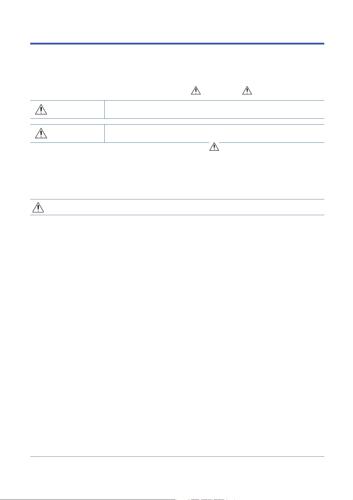
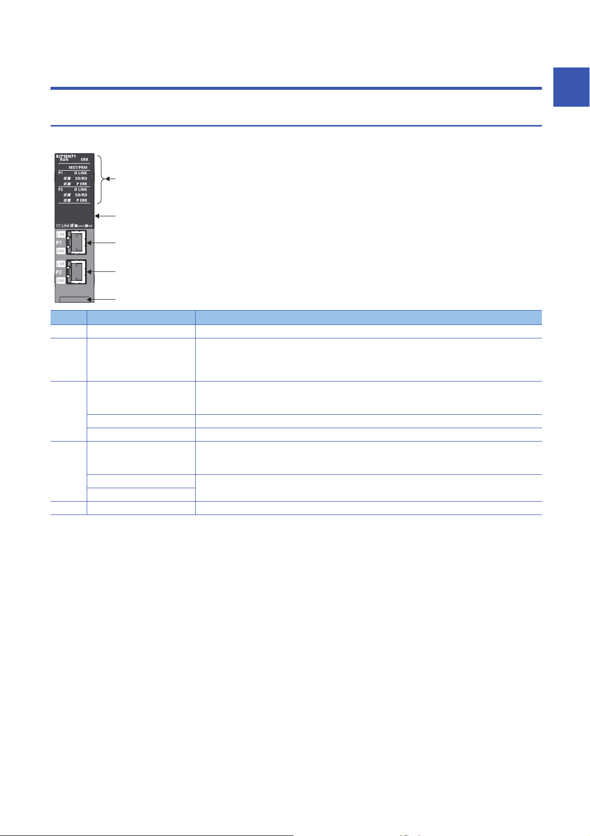
PART NAMES
1
1.1
This section describes the names of each part of the RJ71EN71.
No. Name Description
(1) Operation status indicator LED Indicates the operating status of the module. ( Page 19 Network used and LED indication)
(2) Dot matrix LED Indicates the station number set in the module and the module communication test result. ( Page 22 Dot
(3) Ethernet port (P1) PORT1 connector for network. Connect an Ethernet cable.
(4) Ethernet port (P2) PORT2 connector for network. Connect an Ethernet cable.
(5) Production information marking Shows the production information (16 digits) of the module.
RJ71EN71
matrix LED indication)
For indication of the module communication test result, refer to the following.
MELSEC iQ-R Ethernet User's Manual (Application)
For wiring methods and wiring precautions, refer to the following.
( Page 61 WIRING)
L ER LED Indicates the port status. ( Page 19 Network used and LED indication)
LINK LED Indicates the link status. ( Page 19 Network used and LED indication)
For wiring methods and wiring precautions, refer to the following.
( Page 61 WIRING)
L ER LED Same as the P1 connector
LINK LED
1 PART NAMES
1.1 RJ71EN71
17
Page 20

Available combination of network
Ethernet port (P1 and P2) of the RJ71EN71 can be used in the following network depending on the engineering tool setting.
( GX Works3 Operating Manual)
• Ethernet
• CC-Link IE Controller Network
• CC-Link IE Field Network
• Q-compatible Ethernet
The following table lists the available combination of network and setting in GX Works3.
Network
combination
Ethernet only RJ71EN71 (E+E) Ethernet Ethernet Different network between P1
CC-Link IE Controller
Network only
CC-Link IE Field
Network only
Ethernet + CC-Link IE
Controller Network
Ethernet + CC-Link IE
Field Network
Q-compatible Ethernet RJ71EN71 (Q) Q Compatible
Setting in GX Works3 Description Remarks
*1
Model
RJ71EN71
(CCIEC)
RJ71EN71
(CCIEF)
RJ71EN71
(E+CCIEC)
RJ71EN71
(E+CCIEF)
Port 1
network type
CC-Link IE
Control
CC-Link IE Field CC-Link IE Field P1 and P2 can be connected to
Ethernet CC-Link IE
Ethernet CC-Link IE Field P1 can be connected to Ethernet
Ethernet
Port 2
network type
and P2 can be connected to
Ethernet.
CC-Link IE
Control
Control
A setting for replacement from
P1 and P2 can be connected to
CC-Link IE Controller Network
CC-Link IE Field Network
P1 can be connected to Ethernet
and P2 can be connected to CCLink IE Controller Network.
and P2 can be connected to CCLink IE Field Network.
the MELSEC-Q series Ethernet
interface module RJ71EN71 can
be connected to Ethernet without
changing I/O signal and buffer
memory from the MELSEC-Q
series Ethernet interface module.
• P1 and P2 cannot be
connected to different CC-Link
IE Controller Network.
• P1 and P2 cannot be set
different station numbers.
• P1 and P2 cannot be
connected to different CC-Link
IE Field Network.
• P1 and P2 cannot be set
different station numbers.
CC-Link IE Controller Network
cannot be configured in ring
topology.
CC-Link IE Field Network cannot
be configured in ring topology.
• Some parameters cannot be
set.
• P2 cannot be used.
*1 The name in parentheses is the abbreviation of the network type.
• When the RJ71EN71 is used in the redundant system of the CPU module or the system of the remote head
module, CC-Link IE Controller Network and CC-Link IE Field Network cannot be used.
• When the RJ71EN71 is mounted with the Process CPU or Safety CPU, CC-Link IE Controller Network
cannot be used.
18
1 PART NAMES
1.1 RJ71EN71
Page 21

Network used and LED indication
LED indication of the RJ71EN71 differs depending on the network used.
The following table lists the LED indication when each network is used.
When Ethernet or Q-compatible Ethernet is used
LED name Description
RUN LED Indicates the operating status.
*1
ERR LED
MST/PRM LED
D LINK LED
SD/RD LED Indicates the data sending/receiving status.
P ERR LED
IE C LED
IE F LED
L ER LED Indicates the port status when P2 is used in CC-Link IE Controller Network. (L ER LED of P1 is always off)
LINK LED Indicates the link status.
*1
*1
*1
*1*2
*1
*1 The LED is always off in offline mode.
*2 LED indication differs depending on the version of the RJ71EN71.
( MELSEC iQ-R CC-Link IE Controller Network User's Manual (Application))
On: Normal operation
Off: Error ( MELSEC iQ-R Ethernet User's Manual (Application))
Indicates the error status of the module.
On, flashing: Error ( MELSEC iQ-R Ethernet User's Manual (Application))
Off: Normal operation
Indicates the operating status of CC-Link IE Controller Network when P2 is used in CC-Link IE Controller Network. (MST/
PRM LED is always off when CC-Link IE Controller Network is not used)
For the LED indication when CC-Link IE Controller Network is used, refer to the following.
Page 20 When CC-Link IE Controller Network is used
Indicates the operating status of CC-Link IE Field Network when P2 is used in CC-Link IE Field Network. (MST/PRM LED is
always off when CC-Link IE Field Network is not used)
For the LED indication when CC-Link IE Field Network is used, refer to the following.
Page 21 When CC-Link IE Field Network is used
Indicates the data link status of P2 when P2 is used in CC-Link IE Controller Network. (D LINK LED of P1 is always off)
For the LED indication when CC-Link IE Controller Network is used, refer to the following.
Page 20 When CC-Link IE Controller Network is used
Indicates the data link status of P2 when P2 is used in CC-Link IE Field Network. (D LINK LED of P1 is always off)
For the LED indication when CC-Link IE Field Network is used, refer to the following.
Page 21 When CC-Link IE Field Network is used
On: Data being sent or received
Off: Data not sent nor received
Indicates the error status of P1 and P2.
On, flashing: Error ( MELSEC iQ-R Ethernet User's Manual (Application))
Off: Normal operation
Indicates the network type setting status when P2 is used in CC-Link IE Controller Network. (IE C LED of P1 is always off.)
For the LED indication when CC-Link IE Controller Network is used, refer to the following.
Page 20 When CC-Link IE Controller Network is used
Indicates the network type setting status when P2 is used in CC-Link IE Field Network. (IE F LED of P1 is always off.)
For the LED indication when CC-Link IE Field Network is used, refer to the following.
Page 21 When CC-Link IE Field Network is used
For the LED indication when CC-Link IE Controller Network is used, refer to the following.
Page 20 When CC-Link IE Controller Network is used
Indicates the port status when P2 is used in CC-Link IE Field Network. (L ER LED of P1 is always off)
For the LED indication when CC-Link IE Field Network is used, refer to the following.
Page 21 When CC-Link IE Field Network is used
On (green): Link-up (1Gbps)
On (yellow): Link-up (100Mbps)
Off: Link-down, link-up (10Mbps)
1
1 PART NAMES
1.1 RJ71EN71
19
Page 22

When CC-Link IE Controller Network is used
LED name Description
RUN LED Indicates the operating status.
*1
ERR LED
MST/PRM LED
D LINK LED
SD/RD LED Indicates the data sending/receiving status.
P ERR LED
IE C LED
IE F LED Indicates the network type setting status.
L ER LED Indicates the port status.
LINK LED Indicates the link status.
*1
*1
*1
*2
*1 The LED is always off in offline mode.
*2 LED indication differs depending on the version of the RJ71EN71.
( MELSEC iQ-R CC-Link IE Controller Network User's Manual (Application))
On: Normal operation
Off: Error ( MELSEC iQ-R CC-Link IE Controller Network User's Manual (Application))
Indicates the error status of the module.
On, flashing: Error ( MELSEC iQ-R CC-Link IE Controller Network User's Manual (Application))
Off: Normal operation
Indicates the operating status.
On: Operating as a control station
Off: Operating as a normal station
Indicates the data link status.
On: Data link (cyclic transmission being performed)
Flashing: Data link (cyclic transmission stopped)
Off: Data link not performed (disconnection)
On: Data being sent or received (The LED turns on only at the P1 side when setting "Port 1 Network Type" to "CC-Link IE
Control" and "Network Topology" under "Basic Settings" of the control station to "Ring".)
Off: Data not sent nor received
Indicates the error status of P1 and P2.
On, flashing: Error ( MELSEC iQ-R CC-Link IE Controller Network User's Manual (Application))
Off: Normal operation
Indicates the network type setting status.
Always on
Always off
On: Abnormal data received or loopback being performed
Off: Normal data received and loopback not performed
On: Link-up
Off: Link-down
20
1 PART NAMES
1.1 RJ71EN71
Page 23

When CC-Link IE Field Network is used
LED name Description
RUN LED Indicates the operating status.
*1
ERR LED
MST/PRM LED Indicates the operating status.
D LINK LED
SD/RD LED Indicates the data sending/receiving status.
P ERR LED
IE C LED
IE F LED Indicates the network type setting status.
L ER LED Indicates the port status.
LINK LED Indicates the link status.
*1
*1
*2
On: Normal operation
Off: Error ( MELSEC iQ-R CC-Link IE Field Network User's Manual (Application))
Indicates the error status of the module.
On, flashing: Error ( MELSEC iQ-R CC-Link IE Field Network User's Manual (Application))
Off: Normal operation
On: Operating as a master station
Flashing: Operating as a submaster station
Off: Operating as a local station
Indicates the data link status.
On: Data link (cyclic transmission being performed)
Flashing: Data link (cyclic transmission stopped)
Off: Data link not performed (disconnection)
On: Data being sent or received (The LED turns on only at the P1 side when setting "Port 1 Network Type" to "CC-Link IE
Field" and "Network Topology" under "Basic Settings" of the master station to "Ring".)
Off: Data not sent nor received
Indicates the error status of P1 and P2.
On: Error or at error detection on all stations ( MELSEC iQ-R CC-Link IE Field Network User's Manual (Application))
Flashing (500ms interval): A data link faulty station was detected.
Flashing (200ms interval): Error ( MELSEC iQ-R CC-Link IE Field Network User's Manual (Application))
Off: Normal operation
Indicates the network type setting status.
Always off
Always on
On: Abnormal data received or loopback being performed
Off: Normal data received and loopback not performed
On: Link-up
Off: Link-down
*1 The LED is always off in offline mode.
*2 LED indication differs depending on the version of the RJ71EN71.
( MELSEC iQ-R CC-Link IE Controller Network User's Manual (Application))
1
1 PART NAMES
1.1 RJ71EN71
21
Page 24

Dot matrix LED indication
The following table lists the station number indicated on the dot matrix LED.
Network combination Setting in GX Works3 Display
*1
Model
Ethernet only RJ71EN71 (E+E) Ethernet Ethernet Always off
CC-Link IE Controller Network
only
CC-Link IE Field Network only RJ71EN71 (CCIEF) CC-Link IE Field CC-Link IE Field Displays the current station number of CC-
Ethernet + CC-Link IE
Controller Network
Ethernet + CC-Link IE Field
Network
Q-compatible Ethernet RJ71EN71 (Q) Q Compatible Ethernet Always off
In offline mode Displays "" in offline mode.
At major error Undefined
RJ71EN71 (CCIEC) CC-Link IE Control CC-Link IE Control Displays the current station number of CC-
RJ71EN71 (E+CCIEC) Ethernet CC-Link IE Control Displays the current station number of CC-
RJ71EN71 (E+CCIEF) Ethernet CC-Link IE Field Displays the current station number of CC-
Port 1 network type Port 2 network type
Link IE Controller Network.
Station number not set: " "
Control station, normal station: 1 to 120
Link IE Field Network.
Station number not set: " "
Master station: 0
Submaster station, local station: 1 to 120
Link IE Controller Network.
Station number not set: " "
Control station, normal station: 1 to 120
Link IE Field Network.
Station number not set: " "
Master station: 0
Submaster station, local station: 1 to 120
*1 The name in parentheses is the abbreviation of the network type.
22
1 PART NAMES
1.1 RJ71EN71
Page 25
1.2
(2)
(1)
(10)
(9)
(8)
(7)
(5) (6)
(4)
(3)
(2)
(2)
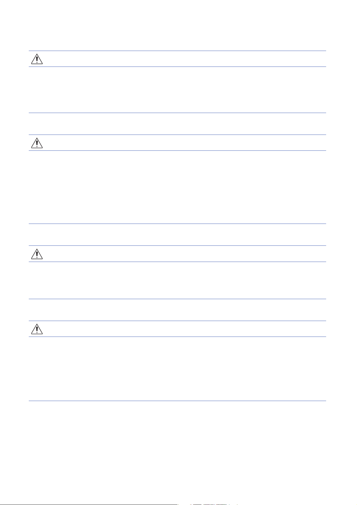
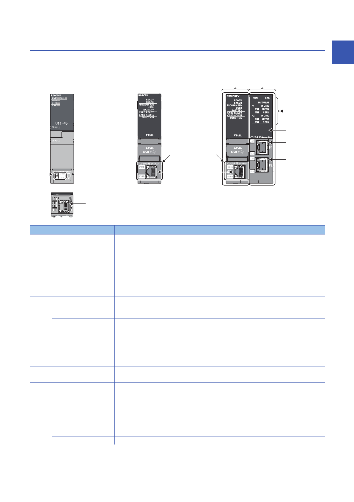
CPU Module
This section describes the part names of the CPU module related to the Ethernet function. For other names of each part, refer
to the following.
MELSEC iQ-R CPU Module User's Manual (Startup)
1
No. Name Description
(1) Built-in Ethernet port part A part to connect the CPU module to Ethernet
(2) Ethernet port A connector to connect the CPU module to the 10BASE-T/100BASE-TX (RJ45 connector)
SPEED LED Indicates the link status.
SD/RD LED Indicates the data sending/receiving status.
(3) Built-in Ethernet port part A part to connect the CPU module to Ethernet
(4) Ethernet port (CPU P1) A connector to connect the CPU module to the 10BASE-T/100BASE-TX (RJ45 connector)
SPEED LED Indicates the link status.
SD/RD LED Indicates the data sending/receiving status.
(5) CPU part A part that works as the CPU module
(6) Network part A part that has the functions of Ethernet, CC-Link IE Controller Network, and CC-Link IE Field Network.
(7) Operation status indicator LED Indicates the operating status of the module. ( Page 25 Network used and LED indication)
(8) Dot matrix LED Displays the station number set in the module and the module communication test result. ( Page 25 Dot
(9) Ethernet port (P1) PORT1 connector for network. Connect an Ethernet cable.
L ER LED Indicates the port status. ( Page 25 Network used and LED indication)
LINK LED Indicates the link status. ( Page 25 Network used and LED indication)
The CPU module determines whether to use 10BASE-T or 100BASE-TX according to the hub.
On: Link-up (100Mbps)
Off: Link-down or link-up (10Mbps)
On: Data being sent or received
Off: Data not sent nor received
The CPU module determines whether to use 10BASE-T or 100BASE-TX according to the hub.
On: Link-up (100Mbps)
Off: Link-down or link-up (10Mbps)
On: Data being sent or received
Off: Data not sent nor received
matrix LED indication)
For display of the module communication test result, refer to the following.
MELSEC iQ-R Ethernet User's Manual (Application)
For wiring methods and wiring precautions, refer to the following.
( Page 61 WIRING)
1 PART NAMES
1.2 CPU Module
23
Page 26

No. Name Description
(10) Ethernet port (P2) PORT2 connector for network. Connect an Ethernet cable.
L ER LED Same as the P1 connector
LINK LED
For wiring methods and wiring precautions, refer to the following.
( Page 61 WIRING)
Available combination of network
Ethernet port (P1 and P2) of the RnENCPU can be used in the following network depending on the engineering tool setting.
( GX Works3 Operating Manual)
• Ethernet
• CC-Link IE Controller Network
• CC-Link IE Field Network
The following table lists the available combination of network and setting in GX Works3.
Network
combination
CC-Link IE Controller
Network only
CC-Link IE Field
Network only
Ethernet + CC-Link IE
Controller Network
Ethernet + CC-Link IE
Field Network
Setting in GX Works3 Description Remarks
*1
Model
_RJ71EN71
(CCIEC)
_RJ71EN71
(CCIEF)
_RJ71EN71
(E+IEC)
_RJ71EN71
(E+IEF)
Port 1 network
type
CC-Link IE Control CC-Link IE Control P1 and P2 can be connected to
CC-Link IE Field CC-Link IE Field P1 and P2 can be connected to
Ethernet CC-Link IE Control P1 can be connected to
Ethernet CC-Link IE Field P1 can be connected to
Port 2 network
type
CC-Link IE Controller Network
CC-Link IE Field Network
Ethernet and P2 can be
connected to CC-Link IE
Controller Network.
Ethernet and P2 can be
connected to CC-Link IE Field
Network.
P1 and P2 cannot be
connected to different CC-Link
IE Controller Network.
P1 and P2 cannot be
connected to different CC-Link
IE Field Network.
CC-Link IE Controller Network
cannot be configured in ring
topology.
CC-Link IE Field Network
cannot be configured in ring
topology.
*1 The name in parentheses is the abbreviation of the network type.
Precautions
The following item cannot be set for the RnENCPU.
• Ethernet only (Port 1 network type: Ethernet, Port 2 network type: Ethernet)
• Q-compatible Ethernet
24
1 PART NAMES
1.2 CPU Module
Page 27

Network used and LED indication
LED indication of the RnENCPU differs depending on the network used. For the LED indication when each network is used,
refer to the following.
• When Ethernet is used: Page 19 When Ethernet or Q-compatible Ethernet is used
• When CC-Link IE Controller Network is used: Page 20 When CC-Link IE Controller Network is used
• When CC-Link IE Field Network is used: Page 21 When CC-Link IE Field Network is used
Dot matrix LED indication
The following table lists the station number indicated on the dot matrix LED.
Network combination Setting in GX Works3 Display
*1
Model
CC-Link IE Controller Network
only
CC-Link IE Field Network only _RJ71EN71 (CCIEF) CC-Link IE Field CC-Link IE Field Displays the current station number of CC-
Ethernet + CC-Link IE
Controller Network
Ethernet + CC-Link IE Field
Network
In offline mode Displays "" in offline mode.
At major error Undefined
_RJ71EN71 (CCIEC) CC-Link IE Control CC-Link IE Control Displays the current station number of CC-
_RJ71EN71 (E+IEC) Ethernet CC-Link IE Control Displays the current station number of CC-
_RJ71EN71 (E+IEF) Ethernet CC-Link IE Field Displays the current station number of CC-
Port 1 network type Port 2 network type
Link IE Controller Network.
Station number not set: " "
Control station, normal station: 1 to 120
Link IE Field Network.
Station number not set: " "
Master station: 0
Submaster station, local station: 1 to 120
Link IE Controller Network.
Station number not set: " "
Control station, normal station: 1 to 120
Link IE Field Network.
Station number not set: " "
Master station: 0
Submaster station, local station: 1 to 120
1
*1 The name in parentheses is the abbreviation of the network type.
1 PART NAMES
1.2 CPU Module
25
Page 28
1.3
(1)
(2)
(3)
(4)
(6)
(3)
(2)
(4)
(5)
(6)
(1)
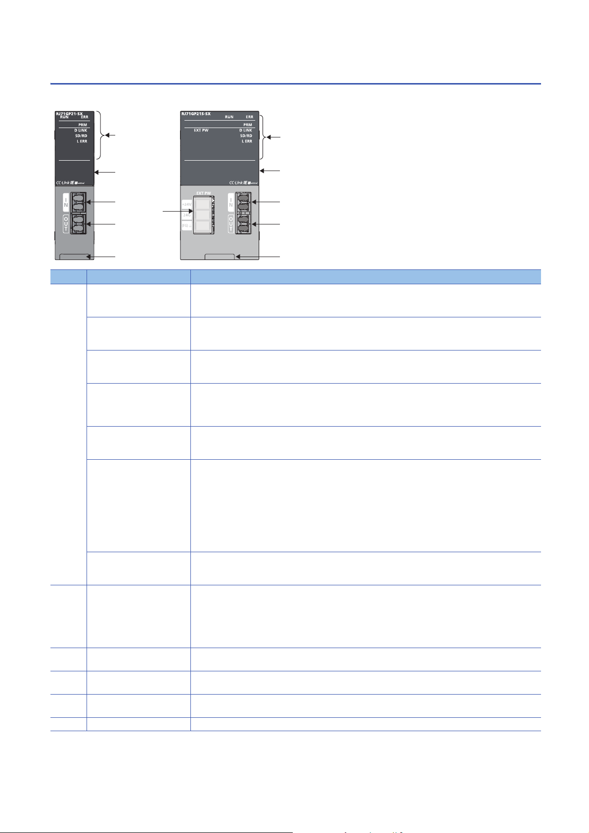
RJ71GP21(S)-SX
This section describes the names of each part of the RJ71GP21(S)-SX.
No. Name Description
(1) RUN LED Indicates the operating status.
*1
ERR LED
PRM LED
D LINK LED
SD/RD LED Indicates the data sending/receiving status.
L ERR LED
EXT PW LED Indicates the external power supply status.
(2) Dot matrix LED Displays the station number set in the module and the module communication test result.
(3) Optical connector (IN
connector)
(4) Optical connector (OUT
connector)
(5) External power supply terminal
block
(6) Production information marking Shows the production information (16 digits) of the module.
*1
*1
*1
On: Normal operation
Off: Error ( MELSEC iQ-R CC-Link IE Controller Network User's Manual (Application))
Indicates the error status of the module.
On, flashing: Error ( MELSEC iQ-R CC-Link IE Controller Network User's Manual (Application))
Off: Normal operation
Indicates the operating status.
On: Operating as a control station
Off: Operating as a normal station
Indicates the data link status.
On: Data link (cyclic transmission being performed)
Flashing: Data link (cyclic transmission stopped)
Off: Data link not performed (disconnection)
On: Data being sent or received
Off: Data not sent nor received
Indicates the line error status.
On: The following errors has occurred in the line connected to the own station port.
• A receive data is faulty (receive frame error).
• Loopback is performed in the own station.
• Cable disconnection
• Cable insertion error
Off: The module or line is in the following status.
• A received data is normal (receive frame normal)
• Loopback is not performed in the own station.
On: The external power being supplied
Off: The external power not supplied
Station number not set: " "
Control station, normal station: 1 to 120
In offline mode: ""
For display of the module communication test result, refer to the following.
( MELSEC iQ-R CC-Link IE Controller Network User's Manual (Application))
A connector to connect the optical fiber cable. Connect to OUT connector of another station.
A connector to connect the optical fiber cable. Connect to IN connector of another station.
A terminal block to connect a wire for the external power supply to the RJ71GP21S-SX.
*2
26
1 PART NAMES
1.3 RJ71GP21(S)-SX
Page 29

*1 The LED is always off in offline mode.
*2 When once a receive frame error is detected, the L ERR LED remains off. ('IN-side error frame detection of own station (SB006E))' or
'OUT-side error frame detection of own station (SB006F)' also remains off.)
To turn off the L ERR LED, perform troubleshooting for when the L ERR LED turns on. ( MELSEC iQ-R CC-Link IE Controller
Network User's Manual (Application))
After taking the action, turn on 'Clear IN-side transmission error count (SB0007)' or 'Clear OUT-side transmission error count (SB0008)'.
1
1 PART NAMES
1.3 RJ71GP21(S)-SX
27
Page 30
1.4
(1)
(2)
(3)
(4)
(5)
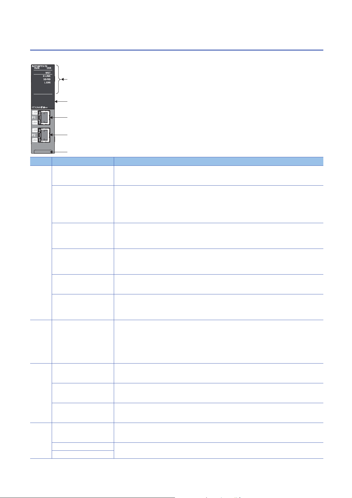
RJ71GF11-T2
This section describes the names of each part of the RJ71GF11-T2.
No. Name Description
(1) RUN LED Indicates the operating status.
On: Normal operation
Off: Error ( MELSEC iQ-R CC-Link IE Field Network User's Manual (Application))
*1
ERR LED
MST LED Indicates the operating status.
D LINK LED
SD/RD LED Indicates the data sending/receiving status.
L ERR LED
(2) Dot matrix LED Displays the station number set in the module and the module communication test result.
(3) Ethernet port (P1) PORT1 connector for CC-Link IE Field Network Connect an Ethernet cable.
L ER LED Indicates the port status.
LINK LED Indicates the link status.
(4) Ethernet port (P2) PORT2 connector for CC-Link IE Field Network Connect an Ethernet cable.
L ER LED Same as the P1 connector
LINK LED
*1
*1
Indicates the error status of the module.
On: Error or at error detection on all stations ( MELSEC iQ-R CC-Link IE Field Network User's Manual
(Application))
Flashing (500ms interval): A data link faulty station was detected.
Flashing (200ms interval): Error ( MELSEC iQ-R CC-Link IE Field Network User's Manual (Application))
Off: Normal operation
On: Operating as a master station
Flashing: Operating as a submaster station
Off: Operating as a local station
Indicates the data link status.
On: Data link (cyclic transmission being performed)
Flashing: Data link (cyclic transmission stopped)
Off: Data link not performed (disconnection)
On: Data being sent or received
Off: Data not sent nor received
Indicates the receive data and line error status. When the L ERR. LED is on, the port in which the error was
detected can be checked with the L ER LED of P1 or P2.
On: Abnormal data received or loopback being performed
Off: Normal data received and loopback not performed
Station number not set: " "
Master station: 0
Submaster station, local station: 1 to 120
In offline mode: ""
For display of the module communication test result, refer to the following.
( MELSEC iQ-R CC-Link IE Field Network User's Manual (Application))
For wiring methods and wiring precautions, refer to the following.
( Page 67 Wiring of CC-Link IE Field Network)
On: Abnormal data received or loopback being performed
Off: Normal data received and loopback not performed
On: Link-up
Off: Link-down
For wiring methods and wiring precautions, refer to the following.
( Page 67 Wiring of CC-Link IE Field Network)
28
1 PART NAMES
1.4 RJ71GF11-T2
Page 31

No. Name Description
(5) Production information marking Shows the production information (16 digits) of the module.
*1 The LED is always off in offline mode.
1
1 PART NAMES
1.4 RJ71GF11-T2
29
Page 32

2
SPECIFICATIONS
This chapter describes the performance specifications and hardware specifications of each module.
2.1
Performance Specifications of Ethernet
The following table lists the performance specifications of Ethernet.
Item RJ71EN71 CPU module
Transmission
specifications
Sending/
receiving data
storage
memory
Ethernet Q-compatible
Ethernet
Data transmission speed 1Gbps/100Mbps/
Communicatio
n mode
Interface RJ45 connector (Auto MDI/MDI-X)
Transmission method Base band
Maximum frame size • 1518 bytes
Jumbo frame Available Not available Available
Maximum segment length 100m (length between hub and node)
Number of
cascade
connections
IP version Compatible with IPv4
Number of simultaneous open
connections
Fixed buffer 5K words 16 1K words 16 5K words 16
Socket communications • 5K words 48
Random access buffer 6K words 1 6K words 1
1000BASE-T Full-duplex Full-duplex
100BASE-TX Full-duplex/half-duplex
10BASE-T Full-duplex/half-duplex
1000BASE-T
100BASE-TX 2 levels maximum
10BASE-T 4 levels maximum
10Mbps
• 9022 bytes (when
jumbo frames are
used)
*3
128 connections
(connections usable
on a program)
(when only P1 is
used)
•5K words 112
(when P1 and P2
are used)
1Gbps*1/100Mbps/
10Mbps
1518 bytes • 1518 bytes
*4
*4
16 connections (connections usable on a program) 64 connections
5K words 16 5K words 48
Built-in
Ethernet port
part
100Mbps/10Mbps 1Gbps/100Mbps/
*2
RnENCPU
(CPU part)
RnENCPU
(network part)
10Mbps
• 9022 bytes (when
jumbo frames are
used)
*3
(connections usable
on a program)
*1 When using 1Gbps, set "Communication Speed" under "Application Settings" to "Automatic Negotiation". ("1Gbps/Full Duplex" cannot
be selected.)
*2 For maximum segment length (length between hubs), consult the manufacturer of the hub used.
*3 Consult the manufacturer of the switching hub used.
*4 This applies when a repeater hub is used. For the number of levels that can be constructed when using a switching hub, consult the
manufacturer of the switching hub used.
The operation of commercial devices used for the following applications is not guaranteed. Check the
operation before using the module.
• Internet (general public line) (Internet-access service offered by an Internet service provider or a
telecommunications carrier)
• Firewall device(s)
• Broadband router(s)
• Wireless LAN
30
2 SPECIFICATIONS
2.1 Performance Specifications of Ethernet
Page 33

2.2
Performance Specifications of CC-Link IE
Controller Network
The following table lists the performance specifications of CC-Link IE Controller Network.
Item RJ71GP21-SX RJ71GP21S-SX RJ71EN71, RnENCPU
(network part)
Maximum number of link points per
network
Maximum number of link points per
station
Transient transmission capacity 1920 bytes maximum
Communication speed 1Gbps
Network topology Duplex loop Line topology, star topology
Communication cable Optical fiber cable which satisfies 1000BASE-SX standard:
Maximum station-to-station distance 550m 100m (conforms to ANSI/TIA/EIA-
Overall cable distance 66000m (when 120 stations are connected) Line topology: 11900m (when 120
Number of cascade connections 20 levels maximum
Maximum number of connectable stations 120 stations (control station: 1, normal station: 119)
Maximum number of networks 239
Maximum number of groups 32
Communication method Token ring Token passing
Optical fiber specifications Standard: IEEE802.3, IEC 60793-2-10 Types A1a.1
Connector specifications Duplex LC connector
Laser class (IEC60825-1) Class 1 laser product
LB 32K points (32768 points, 4K bytes)
LW 128K points (131072 points, 256K bytes)v
LX 8K points (8192 points, 1K bytes)
LY 8K points (8192 points, 1K bytes)
LB 16K points (16384 points, 2K bytes), extended mode: 32K points (32768 points, 4K bytes)
LW 16K points (16384 points, 32K bytes), extended mode: 128K points (131072 points, 256K bytes)
LX 8K points (8192 points, 1K bytes)
LY 8K points (8192 points, 1K bytes)
(coexistence of line topology and
star topology is also possible), and
ring topology
Ethernet cable which satisfies
Multi-mode optical fiber (GI)
*1
Outside diameter of the core/clad: 50m/125m
Transmission loss: 3.5dB/km or lower [=850nm]
Transmission band: 500MHzkm or higher (=850nm)
Standard: IEC 61754-20 Type LC connector
Connection loss: 0.3dB or lower
Polished surface: PC (Physical Contact) polishing
1000BASE-T standard: Category
5e or higher, straight cable
(double shielded, STP)
568-B (Category 5e))
stations are connected)
Star topology: Depends on the
system configuration.
Ring topology: 12000m (when 120
stations are connected)
RJ45 connector
2
*1 When using a CC-Link IE Controller Network-equipped module in a normal station, maximum number of connectable stations differs
depending on the CPU module used in a control station. For details, refer to the user's manual for the control station used.
2 SPECIFICATIONS
2.2 Performance Specifications of CC-Link IE Controller Network
31
Page 34

2.3
Performance Specifications of CC-Link IE Field
Network
The following table lists the performance specifications of CC-Link IE Field Network.
Item RJ71GF11-T2 RJ71EN71, RnENCPU (network part)
Maximum number of link points per network RX 16K points (16384 points, 2K bytes)
RY 16K points (16384 points, 2K bytes)
RWr 8K points (8192 points, 16K bytes)
RWw 8K points (8192 points, 16K bytes)
Maximum number
of link points per
station
Safety
communication
*2
function
Transient transmission capacity 1920 bytes maximum
Communication speed 1Gbps
Network topology Line topology, star topology (coexistence of line topology and star topology is also possible),
Communication cable Ethernet cable which satisfies 1000BASE-T standard:
Maximum station-to-station distance 100m (conforms to ANSI/TIA/EIA-568-B (Category 5e))
Overall cable distance Line topology: 12000m (when 121 stations are connected)
Number of cascade connections 20 levels maximum
Maximum number of connectable stations 121 stations (master station: 1, slave station: 120)
Maximum number of networks 239
Communication method Token passing
Master station RX 16K points (16384 points, 2K bytes)
RY 16K points (16384 points, 2K bytes)
RWr 8K points (8192 points, 16K bytes)
RWw 8K points (8192 points, 16K bytes)
When the
submaster
function is
*3
used
Local station
Maximum number of safety connections
per network
Maximum number of safety connections
per station
Maximum number of safety connections
per the same communication destination
station
Maximum number of link points per
safety connection
*1*3
Master
operating
station
Submaster
operating
*1
station
RX 16K points
RY 16K points (Own station send range is 2K points.)
RWr 8K points
RWw 8K points (Own station send range is 1024 points.)
8K points when communication mode is "High-Speed" (Own station send range is 256 points.)
RX 2K points (assigned for the station number 0 or submaster station)
RY 2K points (assigned for the station number 0 or submaster station)
RWr 1024 points (assigned for the station number 0 or submaster station)
256 points when communication mode is "High-Speed"
RWw 1024 points (assigned for the station number 0 or submaster station)
256 points when communication mode is "High-Speed"
RX 2K points (2048 points, 256 bytes)
RY 2K points (2048 points, 256 bytes)
RWr 1K points (1024 points, 2K bytes)
256 points (512 bytes) when communication mode is "High-Speed"
RWw 1K points (1024 points, 2K bytes)
256 points (512 bytes) when communication mode is "High-Speed"
1814 connections
For the system with the SIL2 Process
CPU: 120 connections
120 connections
1 connection
For the system with the SIL2 Process
CPU: 32 connections
8 words (input: 8 words, output: 8
words)
and ring topology
Category 5e or higher, straight cable (double shielded, STP)
Star topology: Depends on the system configuration.
Ring topology: 12100m (when 121 stations are connected)
*1 The maximum number of points that a master station can assign to one station. A submaster station and a local station can receive the
data from other stations in addition to this number of points.
2 SPECIFICATIONS
32
2.3 Performance Specifications of CC-Link IE Field Network
Page 35

*2 This function is not available for the RJ71EN71. For the RJ71GF11-T2, availability depends on the firmware version.
( MELSEC iQ-R CC-Link IE Field Network User's Manual (Application))
*3 Submaster station and local stations cannot be connected when "Communication Mode" under "Application Settings" is "High-Speed
Remote Net".
2
2 SPECIFICATIONS
2.3 Performance Specifications of CC-Link IE Field Network
33
Page 36

2.4
Hardware Specifications
The following table lists the hardware specifications of each module.
For the hardware specifications of the CPU module, refer to the following.
MELSEC iQ-R CPU Module User's Manual (Startup)
Item RJ71EN71 RJ71GP21-SX RJ71GP21S-SX RJ71GF11-T2
Number of occupied I/O points 32 points 48 points 2 slots (I/O
External power
supply
Internal current consumption (5VDC) 0.82A 0.88A 0.95A 0.82A
External
dimensions
Weight 0.17kg 0.18kg 0.26kg 0.17kg
Voltage No external power supply function 20.4 to 31.2VDC No external power supply
Current 0.28A
Terminal screw
size
Applicable
solderless terminal
Applicable wire
size
Tightning torque 0.42 to 0.58Nm
Allowable
momentary power
failure time
Noise immunity
Height 106mm (Base unit mounting side: 98mm)
Width 27.8mm 56mm
Depth 110mm
assignment: empty 16
points + intelligent 32
points)
M3 screw
R1.25-3
0.3 to 1.25 (22 to 16
AWG)
1ms (level PS1)
Simulator noise 500Vp-p,
noise width 1s, noise
frequency 25 to 60Hz
(noise simulator condition)
32 points
function
34
2 SPECIFICATIONS
2.4 Hardware Specifications
Page 37

3
FUNCTION LIST
3.1
Function List of Ethernet
This section describes the functions of Ethernet. For details on the functions, refer to the following.
MELSEC iQ-R Ethernet User's Manual (Application)
: Available, : Partially available, : Not available
Function Description Availability
RJ71EN71,
RnENCPU
(network
part)
Connection with MELSOFT product and
GOT
SLMP communication Reads/writes the buffer memory, devices, and others from the external
Predefined protocol communication Allows the communication processing only with the program of the start
Socket communications Exchanges arbitrary data with an external device connected by Ethernet
Fixed buffer communication Exchanges arbitrary data between the CPU module and external device
Random access buffer communication Reads/writes data from multiple external devices to the random access
MODBUS/TCP communications Allows the MODBUS/TCP-compatible device connected in the same
Link dedicated instruction communication Reads/writes data from/to other station CPU modules on other networks via
Web server function Monitors and diagnoses the CPU module via network using a Web browser.
File transfer function (FTP server) Reads/writes data in file units using the dedicated FTP commands from an
File transfer function (FTP client) Enables the CPU module, as an FTP client, to transfer files to an FTP
Time setting function (SNTP client) Automatically performs time setting of the CPU module by collecting clock
IP filter function Identifies the IP address of the access source to limit access to the
Remote password Prevents Illegal access of the CPU module from a remote location.
Simple CPU communication function Allows data communications between specified devices at the specified
IP address change function Changes the CPU module's IP address without changing the parameter
Ethernet diagnostics Checks the connection state, protocol state, and line state using the
Automatic detection of connected devices Detects devices supporting iQSS which are connected to the CPU module
Allows the programming and monitoring using the engineering tool, and
monitoring and testing programmable controller from the GOT with Ethernet
connection.
device to an SLMP-compatible device connected in the same network as
the Ethernet-equipped module. Read/write can also be executed to a CPU
module device.
instruction when the protocol data for communication with the external
device is registered using the engineering tool. The protocol required for
communication with the external device (such as temperature controller and
barcode reader) can be set easily using the engineering tool's
communication protocol support function.
over TCP/IP or UDP/IP using dedicated instructions.
using the fixed buffer of the RJ71EN71 and the RnENCPU (network part).
buffer of the RJ71EN71 and the RnENCPU (network part).
network as the RJ71EN71 and the RnENCPU (network part) to read/write
the buffer memory or devices from/to the RJ71EN71 and the RnENCPU
(network part).
Ethernet using the link dedicated instructions.
external device.
server connected over Ethernet by using the file transfer function
instructions.
data from the time information server (SNTP server) on the LAN.
Ethernet-equipped module.
timing just by doing simple settings from an engineering tool.
settings.
engineering tool.
(built-in Ethernet port part), and automatically displays them on "List of
devices" and "Device map area" using an engineering tool.
For details, refer to the following.
iQ Sensor Solution Reference Manual
*1
*1*2
*1
*1
*1*2
*2
CPU module
(built-in
Ethernet
port part)
*3
*3
3
3 FUNCTION LIST
3.1 Function List of Ethernet
35
Page 38

Function Description Availability
RJ71EN71,
RnENCPU
(network
part)
Communication setting reflection Reflects the communication settings (such as IP addresses) in devices
Sensor parameter read/write Reads/writes parameters from/to iQSS-compatible devices.
Redundant system function
CPU module database access (from
external device) function
*2
supporting iQSS in "Device map area" which are connected over Ethernet.
For details, refer to the following.
iQ Sensor Solution Reference Manual
For details, refer to the following.
iQ Sensor Solution Reference Manual
Allows the network to be configured in a redundant system
Operates a database, which is built in an SD memory card inserted into the
CPU module, from an application on a personal computer through the
Ethernet port of the CPU module.
For details, refer to the following.
MELSEC iQ-R CPU Module User's Manual (Application)
*1 This function cannot be used when "Q Compatible Ethernet" is selected for the network type.
*2 Availability depends on the network type and firmware version of the Ethernet-equipped module.
MELSEC iQ-R Ethernet User's Manual (Application)
*3 Availability depends on the firmware version or models.
MELSEC iQ-R Ethernet User's Manual (Application)
CPU module
(built-in
Ethernet
port part)
36
3 FUNCTION LIST
3.1 Function List of Ethernet
Page 39

3.2
Function List of CC-Link IE Controller Network
This section describes the functions of CC-Link IE Controller Network. For details on the functions, refer to the following.
MELSEC iQ-R CC-Link IE Controller Network User's Manual (Application)
Cyclic transmission
: Available, : Partially available, : Not available
Function Description Availability
Control
station
Communications
with other stations
Access to devices
and link devices
Cyclic data integrity assurance Assures the cyclic data integrity in units of 32 bits or station-based units.
Interlink transmission Transfers the link device (LB, LW) data of a CC-Link IE Controller Network-
Cyclic transmission punctuality assurance Keeps the link scan time constant using the following methods.
Group cyclic transmission Divides the stations within the network into groups and specifies the
Number of send points extension by using
extended mode
Cyclic transmission stop and restart Stops the cyclic transmission during debugging and other operations. (Data
Communications
using LB and LW
Communications
using LX and LY
Link refresh Automatically transfers data between the link devices (LB, LW, LX, LY, SB,
Direct access to link
devices
Allows each station to write data to its own send range of a link device (LB,
LW) to send them to all other stations on the network.
Exchanges data between the I/O master station that controls LX and LY and
another station on a one-to-one (1:1) basis.
SW) of the CC-Link IE Controller Network-equipped module and devices of
the CPU module, or between the link devices (SB, SW) of the CC-Link IE
Controller Network-equipped module and the module labels of the CPU
module.
Directly accesses the link devices of the CC-Link IE Controller Networkequipped module from the program.
equipped module to another network module at a relay station.
• Specification of the number of transient transmissions: Specifies the
number of transient transmissions within one link scan.
• Constant link scan: Specifies the link scan time.
stations that share cyclic data (shared group). This setting allows cyclic data
to be shared among the stations having the same shared group number
and not to be received from those having a different shared group number.
Stations having no shared group number assigned will share cyclic data
with all stations.
Sets a CC-Link IE Controller Network-equipped module to the extended
mode using an engineering tool so that the number of send points per
station will be extended to a maximum of 32K points for the link relay (LB)
and 128K points for the link register (LW) in one module.
reception from other stations and data sending from the own station are
stopped.) Also, the stopped cyclic transmission is restarted. Transient
transmission does not stop.
Normal
station
3
Transient transmission
: Available, : Partially available, : Not available
Function Description Availability
Control
station
Communications within the same network Performs the transient transmission to other stations using dedicated
instructions and the engineering tool.
Communications with different networks Performs the transient transmission seamlessly to stations on different
networks using dedicated instructions and the engineering tool.
Dedicated instruction An instruction for using functions of modules. ( MELSEC iQ-R Programming
Manual (Module Dedicated Instructions))
Group transient transmission Sends data to all stations of the same transient transmission group number by
dividing the transient transmission target stations into groups.
3.2 Function List of CC-Link IE Controller Network
3 FUNCTION LIST
Normal
station
37
Page 40

RAS
: Available, : Partially available, : Not available
Function Description Availability
Control
station
Automatic return Automatically returns the station disconnected from the network due to a data
link error to the network when it recovers and restarts data link.
Loopback function Continues data link with normally operating stations even if a cable
disconnection or faulty station occurs.
Control station switching Continues data link with a normal station (sub-control station) that serves as a
control station even if the control station goes down.
Normal station disconnection Disconnects only the normal station where an error occurs, and continues the
data link with the stations that are operating normally. In a line topology, all
stations connected after the faulty station are disconnected.
External power supply function Continues data link among the normally operating stations without being
disrupted at the power-down station even if the CPU module power supply
goes down in a network. Data link is also continued between more than one
station where CPU module power supply has gone down.
Diagnostics
: Available, : Partially available, : Not available
Function Description Availability
Control
station
CC-Link IE Controller Network diagnostics Checks the status of CC-Link IE Controller Network using the engineering tool.
Diagnostics of the
module
Diagnostics of own
network
Diagnostics of other
network
Unit communication
test
Cable test Checks the connection status of the Ethernet cables.
Communication test Checks whether the communication route for transient transmission from the
IP communication
test
The error locations, error causes, and corrective actions can be checked in the
engineering tool.
Checks the hardware inside the CC-Link IE Controller Network-equipped
module. This test should be conducted when the communication is unstable.
*1
own station to the destination station is correct or not.
Checks whether no error occurs in the communication route when the IP
packet transfer function is used.
Normal
station
Normal
station
*1 The optical fiber cable cannot be checked.
3 FUNCTION LIST
38
3.2 Function List of CC-Link IE Controller Network
Page 41

Others
: Available, : Partially available, : Not available
Function Description Availability
Control
station
Reserved station specification Specifies stations reserved for future use. The reserved stations are not
Interrupt Request to CPU Module Makes an interrupt request to the CPU module to start the interrupt program if
IP packet transfer function Performs communications in a protocol such as FTP and HTTP using the
Station number setting using a program Sets the station numbers of a normal station (own station) using a program.
Redundant system function
*1
actually connected, but counted as connected stations. The stations are not
detected as faulty stations even though they are not actually connected.
the interrupt conditions preset using the engineering tool are met. Interrupt
conditions are based on the changes in the link devices (LB, LW, LX) and the
network statuses (SB, SW) checked every link scan or the data reception status
of the channel specified via the RECVS instruction.
specified IP address of an Ethernet device, over CC-Link IE Controller Network.
With this function, two networks of CC-Link IE Controller Network and Ethernet
are not required, resulting in reduced wiring cost.
When there are normal stations with the same program and network
parameters (excluding the station numbers), setting the station numbers using
a program allows project data items other than the station number to be the
same, leading to reduced development work hours. ( MELSEC iQ-R
Programming Manual (Module Dedicated Instructions))
Allows the network to be configured in a redundant system
*1 This function is available only for the RJ71GP21(S)-SX. Availability for the RJ71GP21-SX depends on the firmware version.
MELSEC iQ-R CC-Link IE Controller Network User's Manual (Application)
Normal
station
3
3 FUNCTION LIST
3.2 Function List of CC-Link IE Controller Network
39
Page 42

3.3
Function List of CC-Link IE Field Network
The following table lists the functions of CC-Link IE Field Network. For details on the functions, refer to the following.
MELSEC iQ-R CC-Link IE Field Network User's Manual (Application)
Cyclic transmission
: Available, : Partially available, : Not available
Function Description Availability
Master
station,
submaster
station
Communications
with other stations
Access to devices
and link devices
Cyclic data integrity assurance Assures the cyclic data integrity in units of 32 bits or station-based units.
Interlink transmission Transfers data in the link devices of the master station or submaster station to
Mode selection for cyclic transmission Selects the mode for optimizing the performance of cyclic transmission based
Sequence scan synchronization
specification
Cyclic transmission punctuality assurance Keeps the link scan time constant by setting the constant link scan time.
Input status setting for data link faulty
station
Output status setting for CPU STOP Selects whether cyclic data output is held or cleared when the CPU module
Output status setting for CPU stop error Selects whether cyclic transmission output is held or cleared when a stop error
Cyclic transmission stop and restart Stops the cyclic transmission during debugging and other operations. (Data
Communications
using RX and RY
Communications
using RWr and
RWw
Link refresh Automatically transfers data between the link device of the master/local
Direct access to link
devices
Communicates I/O data in units of bits between the master station and other
stations.
Communicates I/O data in units of words between the master station and other
stations.
module and the device of the CPU module
Directly accesses the link devices of the master/local module from the
program.
another network module on a relay station.
on the cyclic transmission and transient transmission frequency. The mode is
selected from "Normal", "High-Speed", or "High-Speed Remote Net".
Selects whether link scan is set to asynchronous or synchronous with the
sequence scan of the CPU module.
Selects whether input data from another station where a data link error occurs
is cleared or held.
mounted with a master/local module is set to STOP.
occurs in the CPU module which a master/local module is mounted with.
reception from a slave station and data sending from the own station are
stopped.) Also, the stopped cyclic transmission is restarted. Transient
transmission does not stop.
*1
Local
station
*1 The "High-Speed Remote Net" mode can be set only for the master station.
Availability of "High-Speed Remote Net" depends on the firmware version of the CC-Link IE Field Network-equipped master/local
module.
MELSEC iQ-R CC-Link IE Field Network User's Manual (Application)
Transient transmission
: Available, : Partially available, : Not available
Function Description Availability
Communications within the same network Performs the transient transmission to other stations using dedicated
Communications with different networks Performs the transient transmission seamlessly to stations on different
Dedicated instruction An instruction for using functions of modules. ( MELSEC iQ-R
3 FUNCTION LIST
40
3.3 Function List of CC-Link IE Field Network
instructions and the engineering tool.
networks using dedicated instructions and the engineering tool.
Programming Manual (Module Dedicated Instructions))
Master
station,
Local
station
submaster
station
Page 43

RAS
: Available, : Partially available, : Not available
Function Description Availability
Master
station,
submaster
station
Slave station disconnection Disconnects only the slave station where an error occurs, and continues the
data link with the stations that are operating normally. In a line topology, all
stations connected after the faulty station are disconnected.
Automatic return Automatically returns the station disconnected from the network due to a data
link error to the network when it recovers and restarts data link.
Loopback function Continues data link with normal stations even if a cable disconnection or faulty
station occurs. All stations after the cable disconnection point or faulty station
are disconnected in a line topology. By using this function with ring topology,
data link continues with normal stations.
Submaster function Allows the submaster station to control slave stations instead of the master
station when the master station is disconnected in a system where the master
station and submaster station are connected on the same network. Using this
function prevents the entire network from going down due to disconnection of
the master station.
Diagnostics
: Available, : Partially available, : Not available
Function Description Availability
Master
station,
submaster
station
CC-Link IE Field Network diagnostics Checks the status of CC-Link IE Field Network using the engineering tool. The
error locations, error causes, and corrective actions can be checked in the
engineering tool.
Diagnostics of the
module
Diagnostics of own
network
Diagnostics of other
network
Unit communication
test
Cable test Checks the connection status of the Ethernet cables.
Communication test Checks whether the communication route for transient transmission from the
IP communication
test
Checks the hardware of the master/local module. This test should be
conducted when the communication is unstable.
own station to the destination station is correct or not.
Checks whether no error occurs in the communication path when the IP
packet transfer function is used.
Local
station
3
Local
station
Others
: Available, : Partially available, : Not available
Function Description Availability
Master
station,
submaster
station
*3*4
CC-Link IE Field Network synchronous
communication function
Reserved station specification Specifies stations reserved for future use. The reserved stations are not
*1*2
Synchronizes control intervals between slave stations over CC-Link IE Field
Network according to synchronization cycle specified in the master station.
This allows different slave stations on the same network to operate with the
same timing.
( MELSEC iQ-R Inter-Module Synchronization Function Reference
Manual)
actually connected, but counted as connected stations. The stations are not
detected as faulty stations even though they are not actually connected.
3.3 Function List of CC-Link IE Field Network
3 FUNCTION LIST
Local
station
41
Page 44

Function Description Availability
Master
station,
Local
station
submaster
station
Temporary cancel of the reserved station
setting
Error invalid station and temporary error
invalid station setting
Interrupt request to CPU module Checks interrupt conditions every link scan, and makes an interrupt request to
IP packet transfer function Enables communications in a protocol such as FTP and HTTP using the
Station number setting using a program Sets the station numbers of a local station (own station) using a program.
Automatic detection of connected devices Reduces the time of setting parameters by automatically reading information
Sensor parameter read/write Reads/writes parameters of a slave station from/to a module.
iQ Sensor Solution data backup/restoration
function
Redundant system function
Safety
communication
*5
function
Setting to wait cyclic data receive after
system switching
*5
*5
System with the
Safety CPU
System with the
SIL2 Process CPU
Temporarily cancels the reserved station specification without changing the
parameters.
Prevents the master station from detecting a slave station as a faulty station
even if the slave station is disconnected during data link. This function is used
to replace a slave station during data link, for instance.
the CPU module to start the interrupt program if the interrupt conditions are
met.
specified IP address of an Ethernet device, over CC-Link IE Field Network.
With this function, two networks of CC-Link IE Field Network and Ethernet are
not required, resulting in reduced wiring cost.
When there are local stations with the same program and network parameters
(excluding the station numbers), setting the station numbers using a program
allows project data items other than the station number to be the same,
leading to reduced development work hours. ( MELSEC iQ-R
Programming Manual (Module Dedicated Instructions))
of slave stations.
For details, refer to the following.
iQ Sensor Solution Reference Manual
The parameters of multiple slave stations with the same model or same device
version can be batch read or written at once.
Set parameters from "Parameter Processing of Slave Station" or "The
Parameter of Same Slave Station" of "Network Configuration" on "Basic
Settings". ( MELSEC iQ-R CC-Link IE Field Network User's Manual
(Application))
For details, refer to the following.
iQ Sensor Solution Reference Manual
Backs up the setting data of the slave station into the SD memory card of the
CPU module on the master station.
The setting data backed up on the SD memory card of the CPU module on the
master station is restored into the slave module.
For details, refer to the following.
iQ Sensor Solution Reference Manual
Allows the network to be configured in a redundant system
Establishes a safety connection and enables one-on-one safety
communications periodically between safety stations in the same network.
Establishes a safety connection and enables one-on-one safety
communications periodically between safety stations in the same network.
With a redundant configuration of RJ71GF11-T2 or remote head modules, the
new control system can continue safety communications by the system
switching if an error occurs in the control system.
When system switching occurs in the redundant line structure of CC-Link IE
Field Network, set this item to start the execution of the program in the new
control system with new cyclic data obtained after system switching.
For details, refer to the following.
MELSEC iQ-R CPU Module User's Manual (Application)
(Master
station only)
(Master
station only)
(Master
station only)
(Master
station only)
(Master
station only)
(Master
station only)
*3
*1 When the network synchronous communication is performed with local stations, set the inter-module synchronization cycle to any of the
following.
0.888ms
1.777ms
3.555ms
7.111ms
0.8 to 10.0ms (set in increments of 0.05ms)
For the inter-module synchronization cycle when the network synchronous communication is performed with the slave stations other
than local stations, refer to the manual for the slave station used.
For the setting method of the inter-module synchronization cycle, refer to the following.
MELSEC iQ-R Inter-Module Synchronization Function Reference Manual
42
3 FUNCTION LIST
3.3 Function List of CC-Link IE Field Network
Page 45

*2 The network synchronous communication cannot be performed with the stations in a redundant system.
*3 This function cannot be used in the network including the submaster station.
*4 This function cannot be used when the control CPU of the CC-Link IE Field Network-equipped master/local module is the Safety CPU.
*5 This function is available only for the RJ71GF11-T2. Availability depends on the firmware version.
MELSEC iQ-R CC-Link IE Field Network User's Manual (Application)
3
3 FUNCTION LIST
3.3 Function List of CC-Link IE Field Network
43
Page 46

4
This chapter describes the procedures before operation.
1.
Configure the system and set the parameters which are required for start-up.
• Wiring ( Page 61 WIRING)
• Parameter setting ( User's Manual (Application) for each network)
2.
Using network diagnostics, check if the cables are connected properly and communication is performed normally with the
configured parameters.
For details, refer to the following.
User's Manual (Application) for each network
3.
Create a program. For details, refer to the following.
Page 69 COMMUNICATION EXAMPLES
PROCEDURES BEFORE OPERATION
Network construction
Network diagnostics
Programming
44
4 PROCEDURES BEFORE OPERATION
Page 47

MEMO
4
4 PROCEDURES BEFORE OPERATION
45
Page 48

5
Ethernet
This chapter describes the system configuration of each network.
SYSTEM CONFIGURATION
For applicable CPU modules and the number of mountable modules, refer to the following.
MELSEC iQ-R Module Configuration Manual
46
5 SYSTEM CONFIGURATION
Page 49

5.1
(3) (3)
(1)
(2)
(4)
*1
This section describes the system configuration of Ethernet.
Ethernet Configuration
Direct connection to an engineering tool
Engineering tool can be directly connected only with a single Ethernet cable, without using a hub.
In direct connection, communications can be performed simply by the transfer setup, without setting IP address.
Direct connection can cause an unauthorized connection from a remote location as an Ethernet cable is longer than an USB
cable.
Unauthorized connection can be prevented by setting "Disable" in the following item.
[Navigation window] [Parameter] Target module [Application Settings] [Security] [Disable Direct Connection
with MELSOFT]
Connection with external devices and other stations
Connecting the module with external devices and other stations via Ethernet enables the collection or modification of
programmable controller data, monitoring of CPU module operation, status control, and data communication.
5
(1) Own station
(2) External device
(3) Another station
(4) Engineering tool
*1 Connection is available with the CPU module which supports communications using a network number or a station number. (
MELSEC iQ-R Ethernet User's Manual (Application))
Use in a redundant system
The Ethernet-equipped module can be used in a redundant system.
Using the redundant system function enables the module to track a system switching and to issue a system switching request
to the CPU module when a communication error occurs.
For details on the redundant system function, refer to the following.
MELSEC iQ-R Ethernet User's Manual (Application)
5 SYSTEM CONFIGURATION
5.1 Ethernet Configuration
47
Page 50

5.2
IN
OUT
IN
OUT
IN
OUT
n≤120
No.1 No.2 No.n
IN
OUT
IN
OUT
IN
OUT
No.1 No.3 No.2
CC-Link IE Controller Network is configured using optical fiber cables or Ethernet cables.
CC-Link IE Controller Network Configuration
Precautions
CC-Link IE Controller Network of the optical fiber cable and CC-Link IE Controller Network of the Ethernet cable cannot be
combined by using a media converter (optical fiber cable Ethernet cable).
When optical fiber cables are used
Network topology
Connect the RJ71GP21(S)-SX in a loop by using optical fiber cables. (Duplex loop connection)
No. in the figure represents a station number.
The RJ71GP21(S)-SX has IN connector and OUT connector. Connect the IN connector of own station to OUT connector of
another station and OUT connector of own station to IN connector of another station.
Station number and connection position
Modules can be connected in any order regardless of the station number.
Each number in the figure, from No.1 to No.3, represents a station number.
Use in a redundant system
The RJ71GP21(S)-SX can be used in a redundant system.
Using the redundant system function enables the module to track a system switching and to issue a system switching request
to the CPU module when a data link error occurs.
For details on the redundant system function, refer to the following.
MELSEC iQ-R CC-Link IE Controller Network User's Manual (Application)
48
5 SYSTEM CONFIGURATION
5.2 CC-Link IE Controller Network Configuration
Page 51

When Ethernet cables are used
(1)
Network topology
For the Ethernet-equipped module, configure the network in star topology, line topology, or ring topology using the Ethernet
cables.
Star topology and line topology can be combined in a network. Ring topology cannot be combined with star or line topology.
■Star topology
The network is configured into a star shape using a switching hub and Ethernet cables. Normal stations can be easily added
to the network using this topology.
When an error occurs in a normal station, data link can be continued with the stations that are operating normally.
■Line topology
The network is configured into a line using Ethernet cables. A switching hub is not required.
5
When an error occurs in a normal station, the stations connected after the faulty station will be disconnected.
(1) Control station
■Star and line mixed
Star and line topology can be mixed.
5 SYSTEM CONFIGURATION
5.2 CC-Link IE Controller Network Configuration
49
Page 52

■Ring topology
(1)
(1) (2) (3) (4)
The network is configured into a ring using Ethernet cables. A switching hub is not required.
When an error occurs in a normal station, data link can be continued with the stations that are operating normally.
For the RJ71EN71, ring topology is available only when "CC-Link IE Control" is selected as network type for P1 connector.
(1) Control station
Station number and connection position
Modules can be connected in any order regardless of the station number.
(1) Station No.1
(2) Station No.4 (control station)
(3) Station No.3
(4) Station No.2
Cascade connection
Cascade connection of the switching hub is available up to 20 levels.
50
5 SYSTEM CONFIGURATION
5.2 CC-Link IE Controller Network Configuration
Page 53

Precautions when Ethernet cables are used
Addition of the normal stations
Add/remove normal stations one by one. If multiple slave stations are added/removed at a time, all stations on the network will
be reconnected, and an error may momentarily occur in all the stations.
If a normal station is added to a system having 119 normal stations, the system operates as follows.
■When the firmware version of the control station is "05" or later
Baton pass and data link are not performed in the normal station added after the 120th station, and other stations continues
baton pass and data link.
Even if the disconnected stations are returned to a system having 120 or more normal stations, the stations may not start data
link.
• Whether 120 or more normal stations are connected can be checked using 'Number of connected modules
over occurrence status' (SB0099). Number of connected modules detected by 'Number of connected
modules over occurrence status' (SB0099) is the total of the normal stations which are currently connected
and the disconnected stations (normal stations which were previously connected).
• The number of stations which were previously connected can be cleared by executing the network map
update of the CC-Link IE Controller Network diagnostics. ( MELSEC iQ-R CC-Link IE Controller
Network User's Manual (Application))
• A data link error may be momentarily detected in all the stations since all stations on the network will be
reconnected when executing the network map update.
■When the firmware version of the control station is "04" or earlier
All stations will fail and data link cannot be performed.
Incorrectly configured ring topology
Do not use a switching hub for ring topology.
Ring topology
When using a ring topology, select "Ring" in the following setting for the control station.
[Navigation window] [Parameter] [Module Information] Tar ge t m od u le [Basic Settings] [Network Topology]
5
5 SYSTEM CONFIGURATION
5.2 CC-Link IE Controller Network Configuration
51
Page 54

Offline mode station in ring topology
(1) (2)
(3)
(1) (2)
(3)
In following conditions, the station connected to the offline mode station cannot detect loopback
• One of the Ethernet cables connected to the offline mode station is disconnected.
(1) Control station
(2) Station in offline mode
(3) No loopback is detected.
• A station connected to the offline mode station is disconnected.
(1) Control station
(2) Station in offline mode
(3) No loopback is detected.
To detect loopback, set the offline mode station as a reserved station.
When the offline mode station is disconnected, loopback can be detected.
Following stations operate as same as a station in the offline mode.
• A station during the RESET status
• A station with no station number setting
52
5 SYSTEM CONFIGURATION
5.2 CC-Link IE Controller Network Configuration
Page 55

Connecting/disconnecting a cable and powering off/on a device
When the operations listed below are performed, the following will occur depending on the firmware version of the control
station.
Network configuration Operation
Star topology • Powering off and on a normal station or switching hub
• Connecting/disconnecting an Ethernet cable connected to the switching hub
• Disconnecting an Ethernet cable from a normal station and connecting it to another normal station or a switching hub
• Disconnecting more than 9 stations, or half the number of normal stations or more in the system
• Changing the network topology when adding a normal station
Line topology, ring topology • Simultaneously powering off/on multiple stations
• Simultaneously connecting/disconnecting Ethernet cables to/from multiple stations (When a data link faulty station
returns, a data link error will occur in all the stations.)
• Disconnecting more than 9 stations, or half the number of normal stations or more in the system
• Changing the network topology when adding a normal station
■When the firmware version of the control station is "05" or later
The actual network configuration and the network map of the CC-Link IE Controller Network diagnostics may be a mismatch.
Whether mismatch is occurred or not can be checked using 'Network configuration mismatch occurrence status' (SB0098).
When using a ring topology, the following may be occurred.
• The station number of the loopback station cannot be detected correctly.
• Even if a switching hub is used, data link does not stop.
The actual network configuration and network map can be matched by executing the network map update of
the CC-Link IE Controller Network diagnostics. ( MELSEC iQ-R CC-Link IE Controller Network User's
Manual (Application))
A data link error may be momentarily detected in all the stations since all stations on the network will be
reconnected when executing the network map update.
5
■When the firmware version of the control station is "04" or earlier
A data link error may occur in all the stations.
Connected station numbers
Do not duplicate station numbers. Data link may be stopped when the station number is duplicated.
5 SYSTEM CONFIGURATION
5.2 CC-Link IE Controller Network Configuration
53
Page 56

5.3
(1)
CC-Link IE Field Network is configured using Ethernet cables.
CC-Link IE Field Network Configuration
Network topology
For the CC-Link IE Field Network-equipped master/local module, configure the network in star topology, line topology, or ring
topology using the Ethernet cables.
Star topology and line topology can be combined in a network. Ring topology cannot be combined with star or line topology.
■Star topology
The network is configured into a star shape using a switching hub and Ethernet cables. Slave stations can be easily added to
the network using this topology.
When an error occurs in a slave station, data link can be continued with the stations that are operating normally.
■Line topology
The network is configured into a line using Ethernet cables. A switching hub is not required.
When an error occurs in a slave station, the stations connected after the faulty station will be disconnected.
(1) Master station (station No.0)
■Star and line mixed
Star and line topology can be mixed.
54
5 SYSTEM CONFIGURATION
5.3 CC-Link IE Field Network Configuration
Page 57

■Ring topology
(1)
(1) (2) (3) (4)
The network is configured into a ring using Ethernet cables. A switching hub is not required.
When an error occurs in a slave station, data link can be continued with the stations that are operating normally.
For the RJ71EN71, ring topology is available only when "CC-Link IE Field" is selected as network type for P1 connector.
(1) Master station (station No.0)
Station number and connection position
Modules can be connected in any order regardless of the station number.
(1) Station No.1
(2) Station number 0 (master station)
(3) Station No.3
(4) Station No.2
5
5 SYSTEM CONFIGURATION
5.3 CC-Link IE Field Network Configuration
55
Page 58

Cascade connection
Cascade connection of the switching hub is available up to 20 levels.
Up to 4 levels can be connected when the synchronous communication function of CC-Link IE Field is used.
In a redundant system
The RJ71GF11-T2 can be used in a redundant system.
Using the redundant system function enables the module to track a system switching and to issue a system switching request
to the Process CPU (redundant mode) when a data link error occurs.
For details on the redundant system function, refer to the following.
MELSEC iQ-R CC-Link IE Field Network User's Manual (Application)
With the Safety CPU
When the RJ71GF11-T2 is used with the Safety CPU, the safety communication function is available in addition to the
standard communications (cyclic transmission and transient transmission).
For details on the safety communication function with the Safety CPU, refer to the following.
MELSEC iQ-R CC-Link IE Field Network User's Manual (Application)
With the SIL2 Process CPU
When the RJ71GF11-T2 is used with the SIL2 Process CPU, the safety communication function is available in addition to the
standard communications (cyclic transmission and transient transmission).
Also, enables the module to track a system switching and to issue a system switching request to the SIL2 Process CPU when
a data link error occurs.
For details on the safety communication function with the SIL2 Process CPU, refer to the following.
MELSEC iQ-R CC-Link IE Field Network User's Manual (Application)
56
5 SYSTEM CONFIGURATION
5.3 CC-Link IE Field Network Configuration
Page 59

Precautions
Addition of slave stations (including a submaster station)
Add/remove slave stations one by one. If multiple slave stations are added/removed at a time, all stations on the network will
be reconnected, and an error may momentarily occur in all the stations.
If a slave station (including a submaster station) is added to a system having 120 slave stations (including a submaster
station), the system operates as follows.
■When the firmware version of the master station is "05" or later
Baton pass and data link are not performed in the slave stations (including a submaster station) added after the 121st station,
and other stations continues baton pass and data link.
Even if the disconnected stations are returned to a system having 121 or more slave stations (including a submaster station),
the stations may not start data link.
• Whether 121 or more slave stations (including a submaster station) are connected can be checked using
'Number of connected modules over occurrence status' (SB0099). Number of connected modules detected
by 'Number of connected modules over occurrence status' (SB0099) is the total of the slave stations
(including a submaster station) which are currently connected and the disconnected stations (slave stations
which were previously connected).
• The number of stations which were previously connected can be cleared by executing the network map
update of the CC-Link IE Field Network diagnostics. ( MELSEC iQ-R CC-Link IE Field Network User's
Manual (Application))
• A data link error may momentarily occur in all the stations and outputs of the connected slave stations may
turn off since all stations on the network will be reconnected when executing the network map update. Set
output data if needed. ( Page 59 Output hold when a data link error occurs)
■When the firmware version of the master station is "04" or earlier
All stations will fail and data link cannot be performed.
Incorrectly configured ring topology
Do not use a switching hub for ring topology.
Ring topology
When using a ring topology, select "Ring" in the following setting for the master station.
5
[Navigation window] [Parameter] [Module Information] Tar ge t m o d u le [Basic Settings] [Network Topology]
5 SYSTEM CONFIGURATION
5.3 CC-Link IE Field Network Configuration
57
Page 60

Offline mode station in ring topology
(1) (2)
(3)
(1) (2)
(3)
In following conditions, the station connected to the offline mode station cannot detect loopback
• One of the Ethernet cables connected to the offline mode station is disconnected.
(1) Master station
(2) Station in offline mode
(3) No loopback is detected.
• A station connected to the offline mode station is disconnected.
(1) Master station
(2) Station in offline mode
(3) No loopback is detected.
To detect loopback, set the offline mode station as a reserved station.
When the offline mode station is disconnected, loopback can be detected.
Following stations operate as same as a station in the offline mode.
• A station during the RESET status
• A station with no station number setting
58
5 SYSTEM CONFIGURATION
5.3 CC-Link IE Field Network Configuration
Page 61

Connecting/disconnecting a cable and powering off/on a device
When the operations listed below are performed, the following will occur depending on the firmware version of the control
station.
Network configuration Operation
Star topology • Powering off and on a slave station or switching hub
• Connecting/disconnecting an Ethernet cable connected to the switching hub
• Disconnecting an Ethernet cable from a slave station and connecting it to another slave station or a switching hub
• Disconnecting more than 9 stations, or half the number of slave stations or more in the system
• Changing the network topology when adding a slave station
Line topology, ring topology • Simultaneously powering off/on multiple stations
• Simultaneously connecting/disconnecting Ethernet cables to/from multiple stations (When a data link faulty station
returns, a data link error will occur in all the stations.)
• Disconnecting more than 9 stations, or half the number of slave stations or more in the system
• Changing the network topology when adding a slave station
■When the firmware version of the master station is "05" or later
The actual network configuration and the network map of the CC-Link IE Field Network diagnostics may be a mismatch.
Whether mismatch is occurred or not can be checked using 'Network configuration mismatch occurrence status' (SB0098).
When using a ring topology, the following may be occurred.
• The station number of the loopback station cannot be detected correctly.
• Even if a switching hub is used, data link does not stop.
The actual network configuration and network map can be matched by executing the network map update of
the CC-Link IE Field Network diagnostics. ( MELSEC iQ-R CC-Link IE Field Network User's Manual
(Application))
A data link error may momentarily occur in all the stations and outputs of the connected slave stations may
turn off since all stations on the network will be reconnected when executing the network map update. Set
output data if needed. ( Page 59 Output hold when a data link error occurs)
5
■When the firmware version of the master station is "04" or earlier
A data link error may momentarily occur in all the stations and outputs of the connected slave stations may turn off since all
stations on the network will be reconnected. Set output data if needed. ( Page 59 Output hold when a data link error
occurs)
Output hold when a data link error occurs
Setting the following allows to hold the outputs when a data link error occurs.
■Master/local module
Select the "Hold" in the following setting.
[Navigation window] [Parameter] [Module Information] Tar ge t m od u le [Application Settings]
[Supplementary Cyclic Settings] [I/O Maintenance Settings] [Data Link Error Station Setting]
■For a head module whose serial number (first five digits) is "12071" or earlier
Select the "Hold" in the following setting using GX Works2.
Project window [Parameter] [PLC Parameter] [I/O Assignment] [Detailed Setting] button [Error Time Output
Mode]
This setting is not required for a head module whose serial number (first five digits) is "12072" or later.)
Connected station numbers
Do not duplicate station numbers. Data link may be stopped when the station number is duplicated.
5 SYSTEM CONFIGURATION
5.3 CC-Link IE Field Network Configuration
59
Page 62

5.4
Precautions for System Configuration
Connecting devices to the same network
Do not connect the devices as described below. Doing so may cause the disconnection of all stations.
• The devices having different network types (such as CC-Link IE Controller Network and CC-Link IE Controller Network) are
connected to the same network line.
• The Ethernet devices (such as personal computers) in various networks are connected to one switching hub.
Connecting devices to the CPU module (built-in Ethernet port part)
When connecting devices to the CPU module (built-in Ethernet port part), power off the CPU module before connection.
60
5 SYSTEM CONFIGURATION
5.4 Precautions for System Configuration
Page 63

6
This chapter describes the wiring methods, wiring products, and wiring precautions when each network is used.
WIRING
6.1
This section describes the wiring when Ethernet is used.
Ethernet Wiring
Wiring methods
The following describes connection and disconnection of the Ethernet cable.
■Connecting the cable
1.
Push the Ethernet cable connector into the Ethernet-equipped module until it clicks. Pay attention to the connector's
direction.
2.
Lightly pull it to check that it is securely connected.
3.
Check whether the LINK LED of the port connected with an Ethernet cable is on.
*1 The time between the cable connection and the LINK LED turning on may vary. The LINK LED usually turns on in a few seconds. Note,
however, that the time may be extended further if the link-up processing is repeated depending on the status of the device on the line.
Check whether the cables are connected properly if the LINK LED does not turn on. In addition, the LINK LED does not turn on if the
communication speed is 10Mbps. Perform network diagnostics and check whether the cables are connected properly. ( MELSEC iQR Ethernet User's Manual (Application))
■Disconnecting the cable
1.
Press the latch down and unplug the Ethernet cable.
■Precautions
• Place the Ethernet cable in a duct or clamp them. If not, dangling cable may swing or inadvertently be pulled, resulting in
damage to the module or cables or malfunction due to poor contact.
• Do not touch the core of the cable-side or module-side connector, and protect it from dirt or dust. If oil from your hand, dirt
or dust is attached to the core, it can increase transmission loss, arising a problem in data link.
• Check that the Ethernet cable is not disconnected or not shorted and there is no problem with the connector connection.
• When connecting the Ethernet cable, refer to the CC-Link IE Field Network Cable Installation Manual available from the
website of CC-Link Partner Association (www.cc-link.org). The cable installation not following the contents of the manual
may cause malfunction.
• Do not use Ethernet cables with broken latches. Doing so may cause the cable to unplug or malfunction.
• Hold the connector part when connecting and disconnecting the Ethernet cable. Pulling the cable connected to the module
may result in malfunction or damage to the module or cable.
• For connectors without Ethernet cable, attached connector cover should be placed to prevent foreign matter such as dirt or
dust.
• The maximum segment length of the Ethernet cable is 100m. However, the length may be shorter depending on the
operating environment of the cable. For details, contact your cable manufacturer.
• The bend radius of the Ethernet cable is limited. For details, check the specifications of the Ethernet cable to be used.
*1
6
6 WIRING
6.1 Ethernet Wiring
61
Page 64

Wiring products
The following describes the devices used for Ethernet.
An Ethernet-equipped module determines whether to use 1000BASE-T/100BASE-TX/10BASE-T and the full-
duplex/half-duplex communication mode based on the hub. For connection to the hub with no automatic
negotiation function, set the communication mode on the hub side to meet the mode of the Ethernet-equipped
module. (Page 30 Performance Specifications of Ethernet)
■Ethernet cable
Use Ethernet cable that meets the following standards.
Communicati
on speed
*1
1Gbps
100Mbps Category 5 or higher, straight cable (shielded, STP) 100BASE-TX
10Mbps Category 3 or higher, straight cable (shielded, STP) 10BASE-T
*1 The CPU module (built-in Ethernet port part) does not support the communication speed.
Ethernet cable Connector Ty pe
Category 5e or higher, straight cable (shielded, STP) RJ45 connector 1000BASE-T
Category 5e or higher, crossing cable (shielded, STP)
Category 5 or higher, crossing cable (shielded, STP)
Category 3 or higher, straight cable (UTP)
Category 3 or higher, crossing cable (shielded, STP)
Category 3 or higher, crossing cable (UTP)
A communication error may occur due to high-frequency noise from devices other than a programmable
controller in a given connection environment. The following describes countermeasures to be taken on the
Ethernet-equipped module side to avoid high-frequency noise influence.
Wiring
• Do not bundle the cable with the main circuit or power cable or do not place it near those lines.
• Place the cable in a duct.
• When using a UTP cable, use STP cables.
Communication method
• Use TCP/IP for data communications with connected devices.
• Increase the number of retries of communications if needed.
Transmission speed
• Change the communication speed to be slower than the speed of communications connected with an
Ethernet cable in "Communication Speed" of "Application Settings". ( MELSEC iQ-R Ethernet User's
Manual (Application))
■Hubs
Use hubs that support the transmission speed of communication when using hub in the Ethernet.
62
6 WIRING
6.1 Ethernet Wiring
Page 65

6.2
This section describes the wiring when CC-Link IE Controller Network is used.
Wiring of CC-Link IE Controller Network
Optical fiber cable
The following describes the wiring of the optical fiber cable when the RJ71GP21(S)-SX is used.
Wiring methods
The following describes connection and disconnection of the optical fiber cable.
■Connecting the cable
1.
Push the optical fiber cable connector into the RJ71GP21(S)-SX until it clicks. Pay attention to the connector's direction.
2.
Lightly pull it to check that it is securely connected.
■Disconnecting the cable
1.
Press the connector hook down and unplug the optical fiber cable.
■Precautions
• The RJ71GP21(S)-SX has IN connector and OUT connector. Connect the IN connector of own station to OUT connector of
another station and OUT connector of own station to IN connector of another station.
• The bend radius of the optical fiber cable is limited. For details, check the specifications of the cable to be used.
• Place the optical fiber cable in a duct or clamp them. If not, dangling cable may swing or inadvertently be pulled, resulting in
damage to the module or cables or malfunction due to poor contact.
• When handling an optical fiber cable, do not touch the optical fiber core of the cable-side or module-side connector, and
protect it from dirt or dust. If oil from your hand, dirt or dust is attached to the core, it can increase transmission loss, arising
a problem in data link.
• Hold the connector part when connecting or disconnecting the optical fiber cable. Pulling the cable connected to the module
may result in malfunction or damage to the module or cable.
• A tracking cable to connect the redundant function modules is a cable with the same specifications as the optical fiber cable
to connect the RJ71GP21(S)-SX. Do not connect the RJ71GP21(S)-SX and the redundant function module by mistake.
Wiring products
The following describes the devices used for CC-Link IE Controller Network (when optical fiber cables are used).
■Optical fiber cable
Use optical fiber cable that meets the following standards.
Optical fiber cable Connector Type
Optical fiber cable (multimode optical fiber (GI)) Duplex LC
connector
The following conditioning cables:
• IEEE802.3 (1000BASE-SX)
• IEC 60793-2-10 Types A1a.1
6
Optical fiber cables with connectors are available from Mitsubishi Electric System & Service Co., Ltd. (Catalogs of the optical
fiber cables are also available.)
In addition, on-site connector polishing, terminal assembly, and fusion splicing is available. Please consult your local
Mitsubishi representative.
Typ e Model (Manufacturer)
Multi-mode optical fiber (GI) QG series (Mitsubishi Electric System & Service Co., Ltd.)
6 WIRING
6.2 Wiring of CC-Link IE Controller Network
63
Page 66

External power supply
FG
+24V
24G
AC
AC
DC
24VDC
The following describes wiring of the external power supply when the RJ71GP21S-SX is used.
Wiring diagram
Wiring products
The table below shows applicable solderless terminals connected to the external power supply terminal block. When wiring,
use applicable wires and an appropriate tightening torque. Use UL Listed solderless terminals and, for processing, use a tool
recommended by their manufacturer.
Solderless terminal Wire
Model Tightening torque Diameter Typ e Material Temperature rating
R1.25-3 0.42 to 0.58Nm 22 to 16 AWG Stranded/solid Copper 75 or more
Precaution
Shut off the external power supply (all phases) with external devices before connecting to the external power supply terminal
block. Failure to do so may result in electric shock or cause the module to fail or malfunction.
64
6 WIRING
6.2 Wiring of CC-Link IE Controller Network
Page 67

Ethernet cables
The following describes wiring of Ethernet cables when the RJ71EN71 or the RnENCPU (Network part) is used.
Wiring methods
The following describes connection and disconnection of the Ethernet cable.
■Connecting the cable
1.
Push the Ethernet cable connector into the RJ71EN71 or the RnENCPU (network part) until it clicks. Pay attention to the
connector's direction.
2.
Lightly pull it to check that it is securely connected.
3.
Check whether the LINK LED of the port connected with an Ethernet cable is on.
*1 The time between the cable connection and the LINK LED turning on may vary. The LINK LED usually turns on in a few seconds. Note,
however, that the time may be extended further if the link-up processing is repeated depending on the status of the device on the line. If
the LINK LED does not turn on, refer to the following and take corrective actions.
MELSEC iQ-R CC-Link IE Controller Network User's Manual (Application)
*1
Both P1 connector and P2 connector can be used. (Ring topology is available only when "CC-Link IE Control"
is selected as network type for P1 connector.)
• When only one connector is used in star topology, either P1 connector or P2 connector is applicable.
• When two connectors are used in line topology and ring topology, the cable can be connected between P1
and P1, P2 and P2, or between P1 and P2.
■Disconnecting the cable
1.
Press the latch down and unplug the Ethernet cable.
■Precautions
• Place the Ethernet cable in a duct or clamp them. If not, dangling cable may swing or inadvertently be pulled, resulting in
damage to the module or cables or malfunction due to poor contact.
• Do not touch the core of the cable-side or module-side connector, and protect it from dirt or dust. If oil from your hand, dirt
or dust is attached to the core, it can increase transmission loss, arising a problem in data link.
• Check that the Ethernet cable is not disconnected or not shorted and there is no problem with the connector connection.
• When connecting the Ethernet cable, refer to the CC-Link IE Field Network Cable Installation Manual available from the
website of CC-Link Partner Association (www.cc-link.org). The cable installation not following the contents of the manual
may cause malfunction.
• Do not use Ethernet cables with broken latches. Doing so may cause the cable to unplug or malfunction.
• Hold the connector part when connecting and disconnecting the Ethernet cable. Pulling the cable connected to the module
may result in malfunction or damage to the module or cable.
• For connectors without Ethernet cable, attached connector cover should be placed to prevent foreign matter such as dirt or
dust.
• The maximum station-to-station distance of the Ethernet cable is 100m. However, the length may be shorter depending on
the operating environment of the cable. For details, contact your cable manufacturer.
• The bend radius of the Ethernet cable is limited. For details, check the specifications of the Ethernet cable to be used.
6
6 WIRING
6.2 Wiring of CC-Link IE Controller Network
65
Page 68

Wiring products
The following describes the devices used for CC-Link IE Controller Network (when Ethernet cables are used).
■Ethernet cable
Use Ethernet cable that meets the following standards.
Ethernet cable Connector Typ e
Category 5e or higher, straight cable (double shielded, STP) RJ45 connector The following conditioning cables:
Cables for CC-Link IE Controller Network are available from Mitsubishi Electric System & Service Co., Ltd. (Catalogs for cable
are also available.)
In addition, the connector processing of cable length is available for your preference. Please consult your local Mitsubishi
representative.
Typ e Model (Manufacturer)
Straight cable (double shielded, STP) SC-E5EW series (Mitsubishi Electric System & Service Co., Ltd.)
■Hubs
Use hubs that meet all the conditions listed below. Operation is not guaranteed if the hubs do not meet these conditions.
• Compliance with the IEEE802.3 (1000BASE-T)
• Support of the auto MDI/MDI-X function
• Support of the auto-negotiation function
• Switching hub (layer 2 switch)
*1 A repeater hub is not available.
Typ e Model (Manufacturer)
Industrial switching hub • NZ2EHG-T8N (Mitsubishi Electric Corporation)
*1
• NZ2EHG-T8 (Mitsubishi Electric Corporation) (discontinued)
• IEEE802.3 (1000BASE-T)
• ANSI/TIA/EIA-568-B (Category 5e)
66
6 WIRING
6.2 Wiring of CC-Link IE Controller Network
Page 69

6.3
This section describes the wiring when CC-Link IE Field Network is used.
Wiring of CC-Link IE Field Network
Wiring methods
The following describes connection and disconnection of the Ethernet cable.
■Connecting the cable
1.
Push the Ethernet cable connector into the CC-Link IE Field Network-equipped master/local module until it clicks. Pay
attention to the connector's direction.
2.
Lightly pull it to check that it is securely connected.
3.
Check whether the LINK LED of the port connected with an Ethernet cable is on.
*1 The time between the cable connection and the LINK LED turning on may vary. The LINK LED usually turns on in a few seconds. Note,
however, that the time may be extended further if the link-up processing is repeated depending on the status of the device on the line. If
the LINK LED does not turn on, refer to the following and take corrective actions.
MELSEC iQ-R CC-Link IE Field Network User's Manual (Application)
*1
Both P1 connector and P2 connector can be used. (For the RJ71EN71 and the RnENCPU (network part), ring
topology is available only when "CC-Link IE Field" is selected as network type for P1 connector.)
• When only one connector is used in star topology, either P1 connector or P2 connector is applicable.
• When two connectors are used in line topology and ring topology, the cable can be connected between P1
and P1, P2 and P2, or between P1 and P2.
■Disconnecting the cable
1.
Press the latch down and unplug the Ethernet cable.
6
6 WIRING
6.3 Wiring of CC-Link IE Field Network
67
Page 70

■Precautions
• Place the Ethernet cable in a duct or clamp them. If not, dangling cable may swing or inadvertently be pulled, resulting in
damage to the module or cables or malfunction due to poor contact.
• Do not touch the core of the cable-side or module-side connector, and protect it from dirt or dust. If oil from your hand, dirt
or dust is attached to the core, it can increase transmission loss, arising a problem in data link.
• Check that the Ethernet cable is not disconnected or not shorted and there is no problem with the connector connection.
• When connecting the Ethernet cable, refer to the CC-Link IE Field Network Cable Installation Manual available from the
website of CC-Link Partner Association (www.cc-link.org). The cable installation not following the contents of the manual
may cause malfunction.
• Do not use Ethernet cables with broken latches. Doing so may cause the cable to unplug or malfunction.
• Hold the connector part when connecting and disconnecting the Ethernet cable. Pulling the cable connected to the module
may result in malfunction or damage to the module or cable.
• For connectors without Ethernet cable, attached connector cover should be placed to prevent foreign matter such as dirt or
dust.
• The maximum station-to-station distance of the Ethernet cable is 100m. However, the length may be shorter depending on
the operating environment of the cable. For details, contact your cable manufacturer.
• The bend radius of the Ethernet cable is limited. For details, check the specifications of the Ethernet cable to be used.
Wiring products
The following describes the devices used for CC-Link IE Field Network.
■Ethernet cable
Use Ethernet cable that meets the following standards.
Ethernet cable Connector Type
Category 5e or higher, straight cable (double shielded, STP) RJ45 connector The following conditioning cables:
• IEEE802.3 (1000BASE-T)
• ANSI/TIA/EIA-568-B (Category 5e)
Cables for CC-Link IE Field Network are available from Mitsubishi Electric System & Service Co., Ltd. (Catalogs for cable are
also available.)
In addition, the connector processing of cable length is available for your preference. Please consult your local Mitsubishi
representative.
Typ e Model (Manufacturer)
Straight cable (double shielded, STP) SC-E5EW series (Mitsubishi Electric System & Service Co., Ltd.)
■Hubs
Use hubs that meet all the conditions listed below. Operation is not guaranteed if the hubs do not meet these conditions.
• Compliance with the IEEE802.3 (1000BASE-T)
• Support of the auto MDI/MDI-X function
• Support of the auto-negotiation function
• Switching hub (layer 2 switch)
*1 A repeater hub is not available.
Typ e Model (Manufacturer)
Industrial switching hub • NZ2EHG-T8N (Mitsubishi Electric Corporation)
Use any of the following hubs when using the CC-Link IE Field Network synchronous communication function.
Typ e Model (Manufacturer)
CC-Link IE Field Network synchronous communication-compatible switching
hub
*1
• NZ2EHG-T8 (Mitsubishi Electric Corporation) (discontinued)
DT135TX (Mitsubishi Electric System & Service Co., Ltd.)
68
6 WIRING
6.3 Wiring of CC-Link IE Field Network
Page 71

7
GX Works3 (1) (2)
Ethernet
COMMUNICATION EXAMPLES
7.1
This section describes the socket communications examples using Active open of TCP/IP communications.
Communication Examples of Ethernet
System configuration example
The following system configuration is used to explain socket communications.
System configuration
(1) Sending side (IP address: 192.0.1.100)
(2) Receiving side (IP address: 192.0.1.101)
Sending side
Connect the engineering tool to the CPU module on the sending side and set the parameters.
1.
Set the CPU module as follows.
[Project] [New]
7
2.
Click the [OK] button to add the module labels of the CPU module.
7 COMMUNICATION EXAMPLES
7.1 Communication Examples of Ethernet
69
Page 72

3.
Set the RJ71EN71 as follows.
[Navigation window] [Parameter] [Module Information] Right-click [Add New Module]
4.
Click the [OK] button to add the module labels of the RJ71EN71.
5.
Set the items in "Basic Settings" as follows.
[Navigation window] [Parameter] [Module Information] [RJ71EN71] [Port 1 Module Parameter (Ethernet)]
[Basic Settings]
70
7 COMMUNICATION EXAMPLES
7.1 Communication Examples of Ethernet
Page 73

6.
Set the network configuration as follows.
[Navigation window] [Parameter] [Module Information] [RJ71EN71] [Port 1 Module Parameter (Ethernet)]
[Basic Settings] [External Device Configuration]
7
7.
Write the set parameters to the CPU module. Then reset the CPU module or power off and on the system.
[Online] [Write to PLC]
In this example, default values are used for parameters that are not shown above. For the parameters, refer to
the following.
MELSEC iQ-R Ethernet User's Manual (Application)
Receiving side
Connect the engineering tool to the CPU module on the receiving side and set the parameters.
1.
Set the CPU module and add a module label of the CPU module. The setting method of the CPU module and addition
method of the module label are the same as those of when setting the sending side. ( Page 69 Sending side)
2.
Set the RJ71EN71 and add the module labels of the RJ7171EN71. The setting method of the RJ71EN71 and addition
method of the module label are the same as those of when setting the sending side. ( Page 69 Sending side)
7 COMMUNICATION EXAMPLES
7.1 Communication Examples of Ethernet
71
Page 74

3.
Set the items in "Basic Settings" as follows.
[Navigation window] [Parameter] [Module Information] [RJ71EN71] [Port 1 Module Parameter (Ethernet)]
[Basic Settings]
4.
Set the network configuration as follows.
[Navigation window] [Parameter] [Module Information] [RJ71EN71] [Port 1 Module Parameter (Ethernet)]
[Basic Settings] [External Device Configuration]
72
5.
Write the set parameters to the CPU module. Then reset the CPU module or power off and on the system.
[Online] [Write to PLC]
In this example, default values are used for parameters that are not shown above. For the parameters, refer to
the following.
MELSEC iQ-R Ethernet User's Manual (Application)
7 COMMUNICATION EXAMPLES
7.1 Communication Examples of Ethernet
Page 75

Program example
Sending side
Classification Label name Description Device
Module label RCPU.stSM.bAlways_ON Always on SM400
EN71_EE_1.stPort1.uStatus_HUB_Connection_D.0 Connection status U0\G5192.0
EN71_EE_1.bnCompletion_ConnectionOpen[17] Open completion signal (connection No.17) U0\G1900001.0
EN71_EE_1.bnStatus_ConnectionOpenExecution[17] Open request signal (connection No.17) U0\G1900009.0
EN71_EE_1.uCompletion_EthernetInitialized.0 Initial status U0\G1900024.0
Label to be defined Define global labels as shown below:
7
7 COMMUNICATION EXAMPLES
7.1 Communication Examples of Ethernet
73
Page 76

74
7 COMMUNICATION EXAMPLES
7.1 Communication Examples of Ethernet
Page 77

7
7 COMMUNICATION EXAMPLES
7.1 Communication Examples of Ethernet
75
Page 78

(0) The refresh processing of the module label is performed. (The processing is required for when using the module function block.*1)
When the refresh processing is completed, 'bRunRefresh' (M0) is turned on.
(56) When 'bStartOpen' (M1) is turned on, the open processing of connection No.17 is performed.
When the open processing is completed successfully, 'bOpen_OK' (M3) is turned on.
(252) When 'bStartSend' (M5) is turned on, the send data is stored and data is sent to the external device of connection No.17.
When the data send is completed successfully, 'bSend_OK' (M7) is turned on.
(341) When 'bStartClose' (M13) is turned on, the close processing of connection No.17 is performed.
When the close processing is completed successfully, 'bClose_OK' (M15) is turned on.
*1 The refresh processing using the above FB is not required when the Ethernet function of the CPU module (CPU part for the RnENCPU)
is used.
76
7 COMMUNICATION EXAMPLES
7.1 Communication Examples of Ethernet
Page 79

Receiving side
Classification Label name Description Device
Module label RCPU.stSM.bAlways_ON Always on SM400
EN71_EE_1.bnCompletion_ConnectionOpen[17] Open completion signal (connection No.17) U0\G1900001.0
EN71_EE_1.bnCompletion_ReceiveSocket_FixedBuffer[17] Socket/fixed buffer reception status signal
(connection No.17)
EN71_EE_1.uCompletion_EthernetInitialized.0 Initial status U0\G1900024.0
Label to be defined Define global labels as shown below:
U0\G1900017.0
7
7 COMMUNICATION EXAMPLES
7.1 Communication Examples of Ethernet
77
Page 80

(0) The refresh processing of the module label is performed. (The processing is required for when using the module function block.*1)
When the refresh processing is completed, 'bRunRefresh' (M0) is turned on.
(97) When 'bStartRecv' (M9) is turned on, the data sent by the external device of connection No.17 is received and stored in 'uRecvData' (D2000).
(The device range in which data is stored varies depending on the data length of the received data.)
When the data receive is completed successfully, 'bRecv_OK' (M11) is turned on.
*1 The refresh processing using the above FB is not required when the Ethernet function of the CPU module (CPU part for the RnENCPU)
is used.
• Secure sufficient device areas according to the maximum length of data sent from the send source to
prevent the device areas used for other purposes from being overwritten by the receive data.
• When the data receive is consecutively executed, turn on pbi_bReadTiming (read timing) as shown in the
above program.
• To receive data at shorter intervals than the scan time of the CPU module, add the normally closed contact
of 'bRecv_OK' (M11) and 'bRecv_NG' (M12) to the execution conditions of FB for receiving as shown in the
above program. When there is no normally closed contact of 'bRecv_OK' (M11) and 'bRecv_NG' (M12),
'bStartRecvFB' (M17) is not turned off and on and the FB for receiving may not be executed.
78
7 COMMUNICATION EXAMPLES
7.1 Communication Examples of Ethernet
Page 81

7.2
(4)
(1) (2) (3)
0
1FF
200
3FF
5FF
0
400
1FF
200
3FF
400
5FF
0
1FF
200
3FF
5FF
0
400
1FF
200
3FF
400
5FF
0
1FF
200
3FF
5FF
0
400
1FF
200
3FF
400
5FF
0
1FF
200
3FF
5FF
0
400
1FF
200
3FF
400
5FF
0
1FF
200
3FF
5FF
0
400
1FF
200
3FF
400
5FF
0
B
W
LB
LW
LB
LW
LB
LW
B
W
No.1
No.2
No.3
No.1
No.2
No.3
No.1
No.2
No.3
No.1
No.2
No.3
No.1
No.2
No.3
No.1
No.2
No.3
No.1
No.2
No.3
No.1
No.2
No.3
No.1
No.2
No.3
No.1
No.2
No.3
R04CPUNo.2 No.3No.1R04CPU
Communication Examples of CC-Link IE
Controller Network
This section describes communications between the control station and normal station.
System configuration example
The following system configuration is used to explain communication between the control station and normal station.
System configuration
• Power supply module: R61P
• CPU Module: R04CPU
• CC-Link IE Controller Network-equipped module: RJ71GP21-SX (start I/O number: 0000H to 001FH)
• Input module: RX10 (start I/O number: 0020H to 002FH)
• Output module: RY10R2 (start I/O number: 0030H to 003FH)
7
(1) Control station (station No.1)
(2) Normal station (station No.2)
(3) Normal station (station No.3)
(4) Network No.1
Link device assignment
512 points are assigned to each station.
■LB and LW assignment
Each number in the figure, from No.1 to No.3, represents a station number.
No.1 is control station, and No.2 and No.3 are normal stations.
Send range of station No.
7.2 Communication Examples of CC-Link IE Controller Network
7 COMMUNICATION EXAMPLES
79
Page 82

Setting in the control station
(1)
(2)
(3)
Connect the engineering tool to the CPU module on the control station and set the parameters.
(1) Control station (station No.1)
(2) Normal station (station No.2)
(3) Normal station (station No.3)
1.
Set the CPU module as follows.
[Project] [New]
2.
Click the [OK] button to add the module labels of the CPU module.
80
7 COMMUNICATION EXAMPLES
7.2 Communication Examples of CC-Link IE Controller Network
Page 83

3.
Set the CC-Link IE Controller Network-equipped module as follows.
[Navigation window] [Parameter] [Module Information] Right-click [Add New Module]
4.
Click the [OK] button to add the module labels of the CC-Link IE Controller Network-equipped module.
7
5.
Set the items in "Required Settings" as follows.
[Navigation window] [Parameter] [Module Information] [RJ71GP21-SX] [Required Settings]
6.
Set the network range assignment as follows.
[Navigation window] [Parameter] [Module Information] [RJ71GP21-SX] [Required Settings] [Network
Range Assignment]
7 COMMUNICATION EXAMPLES
7.2 Communication Examples of CC-Link IE Controller Network
81
Page 84

7.
Set the refresh settings as follows.
[Navigation window] [Parameter] [Module Information] [RJ71GP21-SX] [Basic Settings] [Refresh Setting]
8.
Write the set parameters to the CPU module on the control station. Then reset the CPU module or power off and on the
system.
[Online] [Write to PLC]
In this example, default values are used for parameters that are not shown above. For the parameters, refer to
the following.
MELSEC iQ-R CC-Link IE Controller Network User's Manual (Application)
82
7 COMMUNICATION EXAMPLES
7.2 Communication Examples of CC-Link IE Controller Network
Page 85

Setting in the normal stations
Connect the engineering tool to the CPU module on the normal station and set the parameters. Set the station number 2 and
3 to the same setting.
1.
Set the CPU module and add a module label of the CPU module. The setting method of the CPU module and addition
method of the module label are the same as those of the control station. ( Page 80 Setting in the control station)
2.
Set the CC-Link IE Controller Network-equipped module as follows.
[Navigation window] [Parameter] [Module Information] Right-click [Add New Module]
7
3.
Add a module label of the CC-Link IE Controller Network-equipped module. The addition method of the module label is
the same as that of the control station. ( Page 80 Setting in the control station)
4.
Set the items in "Required Settings" as follows. For the station No.3, set "3" to "Station No.".
[Navigation window] [Parameter] [Module Information] [RJ71GP21-SX] [Required Settings]
7 COMMUNICATION EXAMPLES
7.2 Communication Examples of CC-Link IE Controller Network
83
Page 86

5.
Set the refresh settings as follows. Set the station number 2 and 3 of the normal station to the same refresh settings.
[Navigation window] [Parameter] [Module Information] [RJ71GP21-SX] [Basic Settings] [Refresh Setting]
6.
Write the set parameters to the CPU module on the normal station. Then reset the CPU module or power off and on the
system.
[Online] [Write to PLC]
In this example, default values are used for parameters that are not shown above. For the parameters, refer to
the following.
MELSEC iQ-R CC-Link IE Controller Network User's Manual (Application)
84
7 COMMUNICATION EXAMPLES
7.2 Communication Examples of CC-Link IE Controller Network
Page 87

Checking the network status
Once parameters are set for the control station and normal station, the CC-Link IE Controller Network diagnostics of the
engineering tool can be used to check whether data link is normally operating.
1.
Connect the engineering tool to the CPU module on the control station.
2.
Start the CC-Link IE Controller Network diagnostics.
[Diagnostics] [CC-Link IE Control Diagnostics (Optical Cable)]
If the following display appears, data link is normal.
7
When an icon indicating an error is displayed in "Network information display" in the "CC-Link IE Control Diagnostics", use the
CC-Link IE Controller Network diagnostics to identify the cause of the error and take actions. ( MELSEC iQ-R CC-Link IE
Controller Network User's Manual (Application))
7 COMMUNICATION EXAMPLES
7.2 Communication Examples of CC-Link IE Controller Network
85
Page 88

Program example
SET B0
MOV D0 W0 BCD W0 K4Y50
B0LB0B0
W0
LW0
W0
B200 B200LB200
LB0
LW0
LB200
B0
SET B0
B0LB0B0
W0 W0
B200 B200LB200
LB0
LW0
LB200
No.1
No.2
No.1
No.2
No.1
No.2
No.1
No.2
No.1
No.2
No.1
No.2
No.1
No.2
No.1
No.2
R04CPU R04CPURJ71GP21-SX RJ71GP21-SX
(1) (2)
This section describes program examples.
Program example of cyclic transmission
The following shows a program example of cyclic transmission.
■Overview of the program example
D0 of the control station (station No.1) is sent to Y50 to Y5F of the normal station (station No.2) through cyclic transmission.
In the program example, an interlock is established with link relay (LB) and cyclic data is sent.
Each number in the figure, from No.1 to No.2, represents a station number.
No.1 is control station and No.2 is normal station.
Cyclic transmission (range set in the network range assignment)
Link refresh (range set in the refresh settings)
(1) Control station (station No.1)
(2) Normal station (station No.2)
86
7 COMMUNICATION EXAMPLES
7.2 Communication Examples of CC-Link IE Controller Network
Page 89

■Program example
When creating a cyclic communication program, establish an interlock using 'Data link error status of own station' (SB0049)
and 'Data link status of each station' (SW00B0 to SW00B7).
• Control station (station No.1)
Classification Label name Description Device
Module label GP21_1.bDetect_DataLinkError Data link error status of own station SB0049
GP21_1.bnSts_CyclicTransmissionError_Station[2] Data link status of each station (station
No.2)
Label to be defined Define global labels as shown below:
SW00B0.1
7
(6) When 'bSendRequest' (M300) is turned on, the contents of 'uOutputData' (D0) is stored in 'uData' (W0).
When data storage is completed, 'bHandShake1' (B0) is turned on.
Link relay (LB) is sent through cyclic transmission after link register (LW).
(12) When data are sent to the receiving station and 'bHandShake2' (B200) is turned on, 'bHandShake1' (B0) is turned off.
7 COMMUNICATION EXAMPLES
7.2 Communication Examples of CC-Link IE Controller Network
87
Page 90

• Normal station (station No.2)
Classification Label name Description Device
Module label GP21_1.bDetect_DataLinkError Data link error status of own station SB0049
GP21_1.bnSts_CyclicTransmissionError_Station[1] Data link status of each station (station
No.1)
Label to be defined Define global labels as shown below:
SW00B0.0
(6) When 'bHandShake1' (B0) is turned on, the contents of 'uData' (W0) is stored in 'uOutputData' (Y50 to Y5F).
When data storage is completed, 'bHandShake2' (B200) is turned on.
88
7 COMMUNICATION EXAMPLES
7.2 Communication Examples of CC-Link IE Controller Network
Page 91

Program example of error detection in other stations
■Data flow
In the program example, the baton pass status and cyclic transmission status of each station is monitored and some network
errors in other stations are detected in a system configured with three stations.
• When a disconnection or a reconnection of stations is detected, the CC-Link IE Controller Network executes
the line control in all stations to reconstruct the loop.
• During the line control processing, the 'Baton pass status of each station' (SW00A0 to SW00A7) and 'Data
link status of each station' (SW00B0 to SW00B7) are turned on for up to 100ms. (Normally for up to 50ms.)
Therefore, set a value of error monitoring timer to more than 100ms and within the allowable range of your
system.
■Program example
The setting value of error monitoring timer is 200ms.
Classification Label name Description Device
Module label GP21_1.bDetect_BatonPassError Baton pass error status of own station SB0047
GP21_1.bDetect_DataLinkError Data link error status of own station SB0049
GP21_1.bnSts_BatonPassError_Station[1] Baton pass status of each station (station
No.1)
GP21_1.bnSts_BatonPassError_Station[2] Baton pass status of each station (station
No.2)
GP21_1.bnSts_BatonPassError_Station[3] Baton pass status of each station (station
No.3
GP21_1.bnSts_CyclicTransmissionError_Station[1] Data link status of each station (station
No.1)
GP21_1.bnSts_CyclicTransmissionError_Station[2] Data link status of each station (station
No.2)
GP21_1.bnSts_CyclicTransmissionError_Station[3] Data link status of each station (station
No.3)
Label to be defined Define global labels as shown below:
SW00A0.0
SW00A0.1
SW00A0.2
SW00B0.0
SW00B0.1
SW00B0.2
7
(38) Processing program for error detection
7 COMMUNICATION EXAMPLES
7.2 Communication Examples of CC-Link IE Controller Network
89
Page 92

7.3
(1) (2)
(4)
(3)
1000
10FF
1100
11FF
1000
10FF
1100
11FF
X
Y
RX
RY
RX
RY
X
1000
10FF
1100
11FF
0
FF
100
1FF
0
FF
100
1FF
FF
100
1FF
0
FF
100
1FF
0
FF
100
1FF
0
FF
100
1FF
1000
10FF
1100
11FF
RX
YRY
0
No.1
No.2
No.1
No.2
No.1
No.2
No.1
No.2
No.1
No.2
No.1
No.2
No.1
No.2
No.1
No.2
No.1
No.2
No.1
No.2
R04CPU
No.1 No.2No.0
R04CPU
Communication Examples of CC-Link IE Field
Network
This section describes communications between the master station and local station.
System configuration example
The following system configuration is used to explain communication between the master station and local station.
System configuration
• Power supply module: R61P
• CPU Module: R04CPU
• Master/local module: RJ71GF11-T2 (start I/O number: 0000H to 001FH)
• Input module: RX10 (start I/O number: 0020H to 002FH)
• Output module: RY10R2 (start I/O number: 0030H to 003FH)
(1) Master station (station No.0)
(2) Local station (station No.1)
(3) Local station (station No.2)
(4) Network No.1
Link device assignment
256 points are assigned to each station.
■RX/RY assignment
Each number in the figure, from No.0 to No.2, represents a station number.
No.0 is master station, and No.1 and No.2 are local stations.
Send range of station No.
7 COMMUNICATION EXAMPLES
90
7.3 Communication Examples of CC-Link IE Field Network
Page 93

■RWr/RWw assignment
RWr
RWw
RWr
RWw
W
1000
10FF
1100
11FF
0
FF
100
1FF
0
FF
100
1FF
0
FF
100
1FF
0
FF
100
1FF
0
FF
100
1FF
0
FF
100
1FF
0
FF
100
1FF
RWr
W RWw
1000
10FF
1100
11FF
0
FF
100
1FF
W
W
No.1
No.2
No.1
No.2
No.1
No.2
No.1
No.2
No.1
No.2
No.1
No.2
No.1
No.2
No.1
No.2
No.1
No.2
No.1
No.2
No.1 No.2No.0
R04CPU R04CPU
Each number in the figure, from No.0 to No.2, represents a station number.
No.0 is master station, and No.1 and No.2 are local stations.
Send range of station No.
7
7.3 Communication Examples of CC-Link IE Field Network
7 COMMUNICATION EXAMPLES
91
Page 94

Setting in the master station
(1)
(2)
(3)
Connect the engineering tool to the CPU module on the master station and set the parameters.
(1) Master station (station No.0)
(2) Local station (station No.1)
(3) Local station (station No.2)
1.
Set the CPU module as follows.
[Project] [New]
2.
Click the [OK] button to add the module labels of the CPU module.
92
7 COMMUNICATION EXAMPLES
7.3 Communication Examples of CC-Link IE Field Network
Page 95

3.
Set the master/local module as follows.
[Navigation window] [Parameter] [Module Information] Right-click [Add New Module]
4.
Click the [OK] button to add the module labels of the master/local module.
7
5.
Set the items in "Required Settings" as follows.
[Navigation window] [Parameter] [Module Information] [RJ71GF11-T2] [Required Settings]
7 COMMUNICATION EXAMPLES
7.3 Communication Examples of CC-Link IE Field Network
93
Page 96

6.
Set the network configuration as follows.
[Navigation window] [Parameter] [Module Information] [RJ71GF11-T2] [Basic Settings] [Network
Configuration Settings]
7.
Set the refresh settings as follows.
[Navigation window] [Parameter] [Module Information] [RJ71GF11-T2] [Basic Settings] [Refresh Setting]
8.
Write the set parameters to the CPU module on the master station. Then reset the CPU module or power off and on the
system.
[Online] [Write to PLC]
In this example, default values are used for parameters that are not shown above. For the parameters, refer to
the following.
MELSEC iQ-R CC-Link IE Field Network User's Manual (Application)
94
7 COMMUNICATION EXAMPLES
7.3 Communication Examples of CC-Link IE Field Network
Page 97

Setting in the local station
(1)
(2)
(3)
Connect the engineering tool to the CPU module on the local station and set the parameters. Set the station number 1 and 2
to the same setting.
(1) Master station (station No.0)
(2) Local station (station No.1)
(3) Local station (station No.2)
1.
Set the CPU module and add a module label of the CPU module. The setting method of the CPU module and addition
method of the module label are the same as those of the master station. ( Page 92 Setting in the master station)
2.
Set the master/local module as follows.
[Navigation window] [Parameter] [Module Information] Right-click [Add New Module]
7
3.
Add a module label of the master/local module. The addition method of the module label is the same as that of the
master station. ( Page 92 Setting in the master station)
4.
Set the items in "Required Settings" as follows. For station No.2, set "Station No." to "2".
[Navigation window] [Parameter] [Module Information] [RJ71GF11-T2] [Required Settings]
7 COMMUNICATION EXAMPLES
7.3 Communication Examples of CC-Link IE Field Network
95
Page 98

5.
Set the refresh settings as follows. Set the station number 1 and 2 of the local station to the same refresh settings.
[Navigation window] [Parameter] [Module Information] [RJ71GF11-T2] [Basic Settings] [Refresh Setting]
6.
Write the set parameters to the CPU module on the local station. Then reset the CPU module or power off and on the
system.
[Online] [Write to PLC]
In this example, default values are used for parameters that are not shown above. For the parameters, refer to
the following.
MELSEC iQ-R CC-Link IE Field Network User's Manual (Application)
96
7 COMMUNICATION EXAMPLES
7.3 Communication Examples of CC-Link IE Field Network
Page 99

Checking the network status
Once parameters are set for the master station and local station, the CC-Link IE Field Network diagnostics of the engineering
tool can be used to check whether data link is normally operating.
1.
Connect the engineering tool to the CPU module on the master station.
2.
Start the CC-Link IE Field Network diagnostics.
[Diagnostics] [CC-Link IE Field Diagnostics]
If the following display appears, data link is normal.
7
When an icon indicating an error is displayed in "Network Status" in "CC-Link IE Field Diagnostics", use the CC-Link IE Field
Network diagnostics to identify the cause of the error and take actions. ( MELSEC iQ-R CC-Link IE Field Network User's
Manual (Application))
7 COMMUNICATION EXAMPLES
7.3 Communication Examples of CC-Link IE Field Network
97
Page 100

Program example
• Master station (station No.0)
Classification Label name Description Device
Module label GF11_1.bSts_DataLinkError Data link error status of own station SB0049
GF11_1.bnSts_DataLinkError_Station[1] Data link status of each station (station No.1) SW00B0.0
GF11_1.bnSts_DataLinkError_Station[2] Data link status of each station (station No.2) SW00B0.1
Label to be defined Define global labels as shown below:
(20) Communication program with station No.1
(50) Communication program with station No.2
If no response is received for several link scans, the 'Data link status of each station' (SW00B0 to SW00B7) is
determined to be a cyclic transmission faulty station.
98
7 COMMUNICATION EXAMPLES
7.3 Communication Examples of CC-Link IE Field Network
 Loading...