

Mitsubishi Electric RD62P2E, RD62D2, iQ-R, RD62P2 User Manual

MELSEC iQ-R High-Speed Counter Module
User's Manual (Application)
-RD62P2
-RD62P2E
-RD62D2

SAFETY PRECAUTIONS
WARNING
Indicates that incorrect handling may cause hazardous conditions, resulting in
death or severe injury.
CAUTION
Indicates that incorrect handling may cause hazardous conditions, resulting in
minor or moderate injury or property damage.
(Read these precautions before using this product.)
Before using this product, please read this manual and the relevant manuals carefully and pay full attention to safety to handle
the product correctly.
The precautions given in this manual are concerned with this product only. For the safety precautions of the programmable
controller system, refer to the MELSEC iQ-R Module Configuration Manual.
In this manual, the safety precautions are classified into two levels: " WARNING" and " CAUTION".
Under some circumstances, failure to observe the precautions given under " CAUTION" may lead to serious
consequences.
Observe the precautions of both levels because they are important for personal and system safety.
Make sure that the end users read this manual and then keep the manual in a safe place for future reference.
1

[Design Precautions]
WARNING
● Configure safety circuits external to the programmable controller to ensure that the entire system
operates safely even when a fault occurs in the external power supply or the programmable controller.
Failure to do so may result in an accident due to an incorrect output or malfunction.
(1) Emergency stop circuits, protection circuits, and protective interlock circuits for conflicting
operations (such as forward/reverse rotations or upper/lower limit positioning) must be configured
external to the programmable controller.
(2) When the programmable controller detects an abnormal condition, it stops the operation and all
outputs are:
• Turned off if the overcurrent or overvoltage protection of the power supply module is activated.
• Held or turned off according to the parameter setting if the self-diagnostic function of the CPU
module detects an error such as a watchdog timer error.
(3) All outputs may be turned on if an error occurs in a part, such as an I/O control part, where the
CPU module cannot detect any error. To ensure safety operation in such a case, provide a safety
mechanism or a fail-safe circuit external to the programmable controller. For a fail-safe circuit
example, refer to "General Safety Requirements" in the MELSEC iQ-R Module Configuration
Manual.
(4) Outputs may remain on or off due to a failure of a component such as a relay and transistor in an
output circuit. Configure an external circuit for monitoring output signals that could cause a
serious accident.
● In an output circuit, when a load current exceeding the rated current or an overcurrent caused by a
load short-circuit flows for a long time, it may cause smoke and fire. To prevent this, configure an
external safety circuit, such as a fuse.
● Configure a circuit so that the programmable controller is turned on first and then the external power
supply. If the external power supply is turned on first, an accident may occur due to an incorrect output
or malfunction.
● For the operating status of each station after a communication failure, refer to manuals relevant to the
network. Incorrect output or malfunction due to a communication failure may result in an accident.
● When connecting an external device with a CPU module or intelligent function module to modify data
of a running programmable controller, configure an interlock circuit in the program to ensure that the
entire system will always operate safely. For other forms of control (such as program modification,
parameter change, forced output, or operating status change) of a running programmable controller,
read the relevant manuals carefully and ensure that the operation is safe before proceeding. Improper
operation may damage machines or cause accidents.
2

[Design Precautions]
WARNING
● Especially, when a remote programmable controller is controlled by an external device, immediate
action cannot be taken if a problem occurs in the programmable controller due to a communication
failure. To prevent this, configure an interlock circuit in the program, and determine corrective actions
to be taken between the external device and CPU module in case of a communication failure.
● Do not write any data to the "system area" and "write-protect area" of the buffer memory in the
module. Also, do not use any "use prohibited" signals as an output signal from the CPU module to
each module. Doing so may cause malfunction of the programmable controller system. For the
"system area", "write-protect area", and the "use prohibited" signals, refer to the user's manual for the
module used.
● If a communication cable is disconnected, the network may be unstable, resulting in a communication
failure of multiple stations. Configure an interlock circuit in the program to ensure that the entire
system will always operate safely even if communications fail. Failure to do so may result in an
accident due to an incorrect output or malfunction.
● To maintain the safety of the programmable controller system against unauthorized access from
external devices via the network, take appropriate measures. To maintain the safety against
unauthorized access via the Internet, take measures such as installing a firewall.
● Outputs may remain on or off due to a failure of a transistor for external output. Configure an external
circuit for monitoring output signals that could cause a serious accident.
[Design Precautions]
CAUTION
● During control of an inductive load such as a lamp, heater, or solenoid valve, a large current
(approximately ten times greater than normal) may flow when the output is turned from off to on.
Therefore, use a module that has a sufficient current rating.
● After the CPU module is powered on or is reset, the time taken to enter the RUN status varies
depending on the system configuration, parameter settings, and/or program size. Design circuits so
that the entire system will always operate safely, regardless of the time.
● Do not power off the programmable controller or reset the CPU module while the setting values in the
buffer memory are being written. Doing so will make the data in the flash ROM undefined. The values
need to be set in the buffer memory and written to the flash ROM again. Doing so also can cause
malfunction or failure of the module.
● When changing the operating status of the CPU module from external devices (such as the remote
RUN/STOP functions), select "Do Not OPEN in Program" for "Open Method Setting" in the module
parameters. If "OPEN in Program" is selected, an execution of the remote STOP function causes the
communication line to close. Consequently, the CPU module cannot reopen the line, and external
devices cannot execute the remote RUN function.
● Do not install the control lines or communication cables together with the main circuit lines or power
cables. Keep a distance of 150mm or more between them. Failure to do so may result in malfunction
due to noise.
3

[Installation Precautions]
WARNING
● Shut off the external power supply (all phases) used in the system before mounting or removing the
module. Failure to do so may result in electric shock or cause the module to fail or malfunction.
[Installation Precautions]
CAUTION
● Use the programmable controller in an environment that meets the general specifications in the Safety
Guidelines included with the base unit. Failure to do so may result in electric shock, fire, malfunction,
or damage to or deterioration of the product.
● To mount a module, place the concave part(s) located at the bottom onto the guide(s) of the base unit,
and push in the module until the hook(s) located at the top snaps into place. Incorrect interconnection
may cause malfunction, failure, or drop of the module.
● When using the programmable controller in an environment of frequent vibrations, fix the module with
a screw.
● Tighten the screws within the specified torque range. Undertightening can cause drop of the screw,
short circuit, or malfunction. Overtightening can damage the screw and/or module, resulting in drop,
short circuit, or malfunction.
● When using an extension cable, connect it to the extension cable connector of the base unit securely.
Check the connection for looseness. Poor contact may cause malfunction.
● When using an SD memory card, fully insert it into the SD memory card slot. Check that it is inserted
completely. Poor contact may cause malfunction.
● Securely insert an extended SRAM cassette into the cassette connector of the CPU module. After
insertion, close the cassette cover and check that the cassette is inserted completely. Poor contact
may cause malfunction.
● Do not directly touch any conductive parts and electronic components of the module, SD memory
card, extended SRAM cassette, or connector. Doing so can cause malfunction or failure of the
module.
[Wiring Precautions]
WARNING
● Shut off the external power supply (all phases) used in the system before installation and wiring.
Failure to do so may result in electric shock or cause the module to fail or malfunction.
● After installation and wiring, attach the included terminal cover to the module before turning it on for
operation. Failure to do so may result in electric shock.
4

[Wiring Precautions]
CAUTION
● Individually ground the FG and LG terminals of the programmable controller with a ground resistance
of 100 ohms or less. Failure to do so may result in electric shock or malfunction.
● Use applicable solderless terminals and tighten them within the specified torque range. If any spade
solderless terminal is used, it may be disconnected when the terminal screw comes loose, resulting in
failure.
● Check the rated voltage and signal layout before wiring to the module, and connect the cables
correctly. Connecting a power supply with a different voltage rating or incorrect wiring may cause fire
or failure.
● Connectors for external devices must be crimped or pressed with the tool specified by the
manufacturer, or must be correctly soldered. Incomplete connections may cause short circuit, fire, or
malfunction.
● Securely connect the connector to the module. Poor contact may cause malfunction.
● Place the cables in a duct or clamp them. If not, dangling cable may swing or inadvertently be pulled,
resulting in damage to the module or cables or malfunction due to poor contact. Do not clamp the
extension cables with the jacket stripped. Doing so may change the characteristics of the cables,
resulting in malfunction.
● Check the interface type and correctly connect the cable. Incorrect wiring (connecting the cable to an
incorrect interface) may cause failure of the module and external device.
● Tighten the terminal screws or connector screws within the specified torque range. Undertightening
can cause drop of the screw, short circuit, fire, or malfunction. Overtightening can damage the screw
and/or module, resulting in drop, short circuit, fire, or malfunction.
● When disconnecting the cable from the module, do not pull the cable by the cable part. For the cable
with connector, hold the connector part of the cable. For the cable connected to the terminal block,
loosen the terminal screw. Pulling the cable connected to the module may result in malfunction or
damage to the module or cable.
● Prevent foreign matter such as dust or wire chips from entering the module. Such foreign matter can
cause a fire, failure, or malfunction.
● A protective film is attached to the top of the module to prevent foreign matter, such as wire chips,
from entering the module during wiring. Do not remove the film during wiring. Remove it for heat
dissipation before system operation.
● Programmable controllers must be installed in control panels. Connect the main power supply to the
power supply module in the control panel through a relay terminal block. Wiring and replacement of a
power supply module must be performed by qualified maintenance personnel with knowledge of
protection against electric shock. For wiring, refer to the MELSEC iQ-R Module Configuration Manual.
● For Ethernet cables to be used in the system, select the ones that meet the specifications in the user's
manual for the module used. If not, normal data transmission is not guaranteed.
● Do not install the control lines or communication cables together with the main circuit lines or power
cables. Keep a distance of 150mm or more between them. Failure to do so may result in malfunction
due to noise.
● Ground the shield cable on the encoder side (relay box) with a ground resistance of 100 ohm or less.
Failure to do so may cause malfunction.
5

[Startup and Maintenance Precautions]
WARNING
● Do not touch any terminal while power is on. Doing so will cause electric shock or malfunction.
● Correctly connect the battery connector. Do not charge, disassemble, heat, short-circuit, solder, or
throw the battery into the fire. Also, do not expose it to liquid or strong shock. Doing so will cause the
battery to produce heat, explode, ignite, or leak, resulting in injury and fire.
● Shut off the external power supply (all phases) used in the system before cleaning the module or
retightening the terminal screws, connector screws, or module fixing screws. Failure to do so may
result in electric shock.
[Startup and Maintenance Precautions]
CAUTION
● When connecting an external device with a CPU module or intelligent function module to modify data
of a running programmable controller, configure an interlock circuit in the program to ensure that the
entire system will always operate safely. For other forms of control (such as program modification,
parameter change, forced output, or operating status change) of a running programmable controller,
read the relevant manuals carefully and ensure that the operation is safe before proceeding. Improper
operation may damage machines or cause accidents.
● Especially, when a remote programmable controller is controlled by an external device, immediate
action cannot be taken if a problem occurs in the programmable controller due to a communication
failure. To prevent this, configure an interlock circuit in the program, and determine corrective actions
to be taken between the external device and CPU module in case of a communication failure.
● Do not disassemble or modify the modules. Doing so may cause failure, malfunction, injury, or a fire.
● Use any radio communication device such as a cellular phone or PHS (Personal Handy-phone
System) more than 25cm away in all directions from the programmable controller. Failure to do so
may cause malfunction.
● Shut off the external power supply (all phases) used in the system before mounting or removing the
module. Failure to do so may cause the module to fail or malfunction.
● Tighten the screws within the specified torque range. Undertightening can cause drop of the
component or wire, short circuit, or malfunction. Overtightening can damage the screw and/or module,
resulting in drop, short circuit, or malfunction.
● After the first use of the product, do not mount/remove the module to/from the base unit, and the
terminal block to/from the module, and do not insert/remove the extended SRAM cassette to/from the
CPU module more than 50 times (IEC 61131-2 compliant) respectively. Exceeding the limit may cause
malfunction.
● After the first use of the product, do not insert/remove the SD memory card to/from the CPU module
more than 500 times. Exceeding the limit may cause malfunction.
● Do not touch the metal terminals on the back side of the SD memory card. Doing so may cause
malfunction or failure of the module.
● Do not touch the integrated circuits on the circuit board of an extended SRAM cassette. Doing so may
cause malfunction or failure of the module.
● Do not drop or apply shock to the battery to be installed in the module. Doing so may damage the
battery, causing the battery fluid to leak inside the battery. If the battery is dropped or any shock is
applied to it, dispose of it without using.
6
[Startup and Maintenance Precautions]
CAUTION
● Startup and maintenance of a control panel must be performed by qualified maintenance personnel
with knowledge of protection against electric shock. Lock the control panel so that only qualified
maintenance personnel can operate it.
● Before handling the module, touch a conducting object such as a grounded metal to discharge the
static electricity from the human body. Failure to do so may cause the module to fail or malfunction.
[Operating Precautions]
CAUTION
● When changing data and operating status, and modifying program of the running programmable
controller from an external device such as a personal computer connected to an intelligent function
module, read relevant manuals carefully and ensure the safety before operation. Incorrect change or
modification may cause system malfunction, damage to the machines, or accidents.
● Do not power off the programmable controller or reset the CPU module while the setting values in the
buffer memory are being written to the flash ROM in the module. Doing so will make the data in the
flash ROM undefined. The values need to be set in the buffer memory and written to the flash ROM
again. Doing so can cause malfunction or failure of the module.
[Disposal Precautions]
CAUTION
● When disposing of this product, treat it as industrial waste.
● When disposing of batteries, separate them from other wastes according to the local regulations. For
details on battery regulations in EU member states, refer to the MELSEC iQ-R Module Configuration
Manual.
[Transportation Precautions]
CAUTION
● When transporting lithium batteries, follow the transportation regulations. For details on the regulated
models, refer to the MELSEC iQ-R Module Configuration Manual.
● The halogens (such as fluorine, chlorine, bromine, and iodine), which are contained in a fumigant
used for disinfection and pest control of wood packaging materials, may cause failure of the product.
Prevent the entry of fumigant residues into the product or consider other methods (such as heat
treatment) instead of fumigation. The disinfection and pest control measures must be applied to
unprocessed raw wood.
7

CONDITIONS OF USE FOR THE PRODUCT
(1) Mitsubishi programmable controller ("the PRODUCT") shall be used in conditions;
i) where any problem, fault or failure occurring in the PRODUCT, if any, shall not lead to any major or serious accident;
and
ii) where the backup and fail-safe function are systematically or automatically provided outside of the PRODUCT for the
case of any problem, fault or failure occurring in the PRODUCT.
(2) The PRODUCT has been designed and manufactured for the purpose of being used in general industries.
MITSUBISHI SHALL HAVE NO RESPONSIBILITY OR LIABILITY (INCLUDING, BUT NOT LIMITED TO ANY AND ALL
RESPONSIBILITY OR LIABILITY BASED ON CONTRACT, WARRANTY, TORT, PRODUCT LIABILITY) FOR ANY
INJURY OR DEATH TO PERSONS OR LOSS OR DAMAGE TO PROPERTY CAUSED BY the PRODUCT THAT ARE
OPERATED OR USED IN APPLICATION NOT INTENDED OR EXCLUDED BY INSTRUCTIONS, PRECAUTIONS, OR
WARNING CONTAINED IN MITSUBISHI'S USER, INSTRUCTION AND/OR SAFETY MANUALS, TECHNICAL
BULLETINS AND GUIDELINES FOR the PRODUCT.
("Prohibited Application")
Prohibited Applications include, but not limited to, the use of the PRODUCT in;
• Nuclear Power Plants and any other power plants operated by Power companies, and/or any other cases in which the
public could be affected if any problem or fault occurs in the PRODUCT.
• Railway companies or Public service purposes, and/or any other cases in which establishment of a special quality
assurance system is required by the Purchaser or End User.
• Aircraft or Aerospace, Medical applications, Train equipment, transport equipment such as Elevator and Escalator,
Incineration and Fuel devices, Vehicles, Manned transportation, Equipment for Recreation and Amusement, and
Safety devices, handling of Nuclear or Hazardous Materials or Chemicals, Mining and Drilling, and/or other
applications where there is a significant risk of injury to the public or property.
Notwithstanding the above restrictions, Mitsubishi may in its sole discretion, authorize use of the PRODUCT in one or
more of the Prohibited Applications, provided that the usage of the PRODUCT is limited only for the specific
applications agreed to by Mitsubishi and provided further that no special quality assurance or fail-safe, redundant or
other safety features which exceed the general specifications of the PRODUCTs are required. For details, please
contact the Mitsubishi representative in your region.
INTRODUCTION
Thank you for purchasing the Mitsubishi Electric MELSEC iQ-R series programmable controllers.
This manual describes the functions, parameter settings, and troubleshooting of the relevant products listed below.
Before using this product, please read this manual and the relevant manuals carefully and develop familiarity with the
functions and performance of the MELSEC iQ-R series programmable controller to handle the product correctly.
When applying the program examples provided in this manual to an actual system, ensure the applicability and confirm that it
will not cause system control problems.
Please make sure that the end users read this manual.
Relevant products
RD62P2, RD62P2E, RD62D2
8

MEMO
9

CONTENTS
SAFETY PRECAUTIONS . . . . . . . . . . . . . . . . . . . . . . . . . . . . . . . . . . . . . . . . . . . . . . . . . . . . . . . . . . . . . . . . . . . .1
CONDITIONS OF USE FOR THE PRODUCT . . . . . . . . . . . . . . . . . . . . . . . . . . . . . . . . . . . . . . . . . . . . . . . . . . . .8
INTRODUCTION. . . . . . . . . . . . . . . . . . . . . . . . . . . . . . . . . . . . . . . . . . . . . . . . . . . . . . . . . . . . . . . . . . . . . . . . . . .8
RELEVANT MANUALS . . . . . . . . . . . . . . . . . . . . . . . . . . . . . . . . . . . . . . . . . . . . . . . . . . . . . . . . . . . . . . . . . . . . .12
TERMS . . . . . . . . . . . . . . . . . . . . . . . . . . . . . . . . . . . . . . . . . . . . . . . . . . . . . . . . . . . . . . . . . . . . . . . . . . . . . . . . .12
CHAPTER 1 FUNCTIONS 13
1.1 Pulse Input Modes and Counting Methods. . . . . . . . . . . . . . . . . . . . . . . . . . . . . . . . . . . . . . . . . . . . . . . . . . . 13
Types of pulse input modes. . . . . . . . . . . . . . . . . . . . . . . . . . . . . . . . . . . . . . . . . . . . . . . . . . . . . . . . . . . . . . . . .13
Setting a counting method. . . . . . . . . . . . . . . . . . . . . . . . . . . . . . . . . . . . . . . . . . . . . . . . . . . . . . . . . . . . . . . . . . 16
Reading the present value. . . . . . . . . . . . . . . . . . . . . . . . . . . . . . . . . . . . . . . . . . . . . . . . . . . . . . . . . . . . . . . . . .16
1.2 Selecting a Counter Type . . . . . . . . . . . . . . . . . . . . . . . . . . . . . . . . . . . . . . . . . . . . . . . . . . . . . . . . . . . . . . . . . 17
Linear counter function . . . . . . . . . . . . . . . . . . . . . . . . . . . . . . . . . . . . . . . . . . . . . . . . . . . . . . . . . . . . . . . . . . . .17
Ring counter function. . . . . . . . . . . . . . . . . . . . . . . . . . . . . . . . . . . . . . . . . . . . . . . . . . . . . . . . . . . . . . . . . . . . . . 18
1.3 Coincidence Output Function . . . . . . . . . . . . . . . . . . . . . . . . . . . . . . . . . . . . . . . . . . . . . . . . . . . . . . . . . . . . .20
Coincidence detection interrupt function . . . . . . . . . . . . . . . . . . . . . . . . . . . . . . . . . . . . . . . . . . . . . . . . . . . . . . .23
1.4 Preset Function . . . . . . . . . . . . . . . . . . . . . . . . . . . . . . . . . . . . . . . . . . . . . . . . . . . . . . . . . . . . . . . . . . . . . . . . .24
1.5 Counter Function Selection . . . . . . . . . . . . . . . . . . . . . . . . . . . . . . . . . . . . . . . . . . . . . . . . . . . . . . . . . . . . . . .26
Count error . . . . . . . . . . . . . . . . . . . . . . . . . . . . . . . . . . . . . . . . . . . . . . . . . . . . . . . . . . . . . . . . . . . . . . . . . . . . . 27
Count disable function. . . . . . . . . . . . . . . . . . . . . . . . . . . . . . . . . . . . . . . . . . . . . . . . . . . . . . . . . . . . . . . . . . . . .28
Latch counter function. . . . . . . . . . . . . . . . . . . . . . . . . . . . . . . . . . . . . . . . . . . . . . . . . . . . . . . . . . . . . . . . . . . . . 29
Sampling counter function. . . . . . . . . . . . . . . . . . . . . . . . . . . . . . . . . . . . . . . . . . . . . . . . . . . . . . . . . . . . . . . . . .30
Cycle pulse counter function . . . . . . . . . . . . . . . . . . . . . . . . . . . . . . . . . . . . . . . . . . . . . . . . . . . . . . . . . . . . . . . . 31
1.6 Pulse Measurement Function. . . . . . . . . . . . . . . . . . . . . . . . . . . . . . . . . . . . . . . . . . . . . . . . . . . . . . . . . . . . . .34
1.7 PWM Output Function. . . . . . . . . . . . . . . . . . . . . . . . . . . . . . . . . . . . . . . . . . . . . . . . . . . . . . . . . . . . . . . . . . . .36
CHAPTER 2 PARAMETER SETTINGS 39
2.1 Parameter Setting Procedure. . . . . . . . . . . . . . . . . . . . . . . . . . . . . . . . . . . . . . . . . . . . . . . . . . . . . . . . . . . . . .39
2.2 Basic Setting . . . . . . . . . . . . . . . . . . . . . . . . . . . . . . . . . . . . . . . . . . . . . . . . . . . . . . . . . . . . . . . . . . . . . . . . . . .39
2.3 Application Setting . . . . . . . . . . . . . . . . . . . . . . . . . . . . . . . . . . . . . . . . . . . . . . . . . . . . . . . . . . . . . . . . . . . . . . 41
2.4 Interrupt Setting. . . . . . . . . . . . . . . . . . . . . . . . . . . . . . . . . . . . . . . . . . . . . . . . . . . . . . . . . . . . . . . . . . . . . . . . .42
2.5 Refresh Setting . . . . . . . . . . . . . . . . . . . . . . . . . . . . . . . . . . . . . . . . . . . . . . . . . . . . . . . . . . . . . . . . . . . . . . . . . 43
Refresh processing time . . . . . . . . . . . . . . . . . . . . . . . . . . . . . . . . . . . . . . . . . . . . . . . . . . . . . . . . . . . . . . . . . . . 45
2.6 Preset Setting . . . . . . . . . . . . . . . . . . . . . . . . . . . . . . . . . . . . . . . . . . . . . . . . . . . . . . . . . . . . . . . . . . . . . . . . . .46
CHAPTER 3 TROUBLESHOOTING 47
3.1 Procedure for Troubleshooting . . . . . . . . . . . . . . . . . . . . . . . . . . . . . . . . . . . . . . . . . . . . . . . . . . . . . . . . . . . .47
3.2 Checking Module Status. . . . . . . . . . . . . . . . . . . . . . . . . . . . . . . . . . . . . . . . . . . . . . . . . . . . . . . . . . . . . . . . . .47
3.3 Troubleshooting by Symptom . . . . . . . . . . . . . . . . . . . . . . . . . . . . . . . . . . . . . . . . . . . . . . . . . . . . . . . . . . . . .48
When the count operation does not start. . . . . . . . . . . . . . . . . . . . . . . . . . . . . . . . . . . . . . . . . . . . . . . . . . . . . . . 48
When the count operation is not normal . . . . . . . . . . . . . . . . . . . . . . . . . . . . . . . . . . . . . . . . . . . . . . . . . . . . . . .48
When the coincidence output function does not operate normally . . . . . . . . . . . . . . . . . . . . . . . . . . . . . . . . . . . 49
When a coincidence detection interrupt does not occur . . . . . . . . . . . . . . . . . . . . . . . . . . . . . . . . . . . . . . . . . . .49
When the preset cannot be executed . . . . . . . . . . . . . . . . . . . . . . . . . . . . . . . . . . . . . . . . . . . . . . . . . . . . . . . . .49
When the pulse measurement does not start . . . . . . . . . . . . . . . . . . . . . . . . . . . . . . . . . . . . . . . . . . . . . . . . . . . 49
When the pulses are not measured correctly . . . . . . . . . . . . . . . . . . . . . . . . . . . . . . . . . . . . . . . . . . . . . . . . . . .50
When the PWM output is not correct. . . . . . . . . . . . . . . . . . . . . . . . . . . . . . . . . . . . . . . . . . . . . . . . . . . . . . . . . .50
When the inter-module synchronization function does not operate correctly . . . . . . . . . . . . . . . . . . . . . . . . . . .50
10

Pulse waveform shaping method . . . . . . . . . . . . . . . . . . . . . . . . . . . . . . . . . . . . . . . . . . . . . . . . . . . . . . . . . . . .51
APPENDICES 52
Appendix 1 Module Label . . . . . . . . . . . . . . . . . . . . . . . . . . . . . . . . . . . . . . . . . . . . . . . . . . . . . . . . . . . . . . . . . . . . . . 52
Appendix 2 I/O Signals . . . . . . . . . . . . . . . . . . . . . . . . . . . . . . . . . . . . . . . . . . . . . . . . . . . . . . . . . . . . . . . . . . . . . . . .54
List of I/O signals. . . . . . . . . . . . . . . . . . . . . . . . . . . . . . . . . . . . . . . . . . . . . . . . . . . . . . . . . . . . . . . . . . . . . . . . . 54
Input signals . . . . . . . . . . . . . . . . . . . . . . . . . . . . . . . . . . . . . . . . . . . . . . . . . . . . . . . . . . . . . . . . . . . . . . . . . . . . 55
Output signals . . . . . . . . . . . . . . . . . . . . . . . . . . . . . . . . . . . . . . . . . . . . . . . . . . . . . . . . . . . . . . . . . . . . . . . . . . .57
Appendix 3 Buffer Memory Areas. . . . . . . . . . . . . . . . . . . . . . . . . . . . . . . . . . . . . . . . . . . . . . . . . . . . . . . . . . . . . . . .60
List of buffer memory addresses . . . . . . . . . . . . . . . . . . . . . . . . . . . . . . . . . . . . . . . . . . . . . . . . . . . . . . . . . . . . .60
Details of buffer memory addresses . . . . . . . . . . . . . . . . . . . . . . . . . . . . . . . . . . . . . . . . . . . . . . . . . . . . . . . . . .62
Appendix 4 Operation Examples of When the Remote Head Module Is Mounted . . . . . . . . . . . . . . . . . . . . . . . . . 69
System configuration example . . . . . . . . . . . . . . . . . . . . . . . . . . . . . . . . . . . . . . . . . . . . . . . . . . . . . . . . . . . . . .69
Setting in the master station . . . . . . . . . . . . . . . . . . . . . . . . . . . . . . . . . . . . . . . . . . . . . . . . . . . . . . . . . . . . . . . .70
Setting in the intelligent device station . . . . . . . . . . . . . . . . . . . . . . . . . . . . . . . . . . . . . . . . . . . . . . . . . . . . . . . .73
Checking the network status . . . . . . . . . . . . . . . . . . . . . . . . . . . . . . . . . . . . . . . . . . . . . . . . . . . . . . . . . . . . . . . . 77
Program examples . . . . . . . . . . . . . . . . . . . . . . . . . . . . . . . . . . . . . . . . . . . . . . . . . . . . . . . . . . . . . . . . . . . . . . .77
Appendix 5 Added or Changed Functions. . . . . . . . . . . . . . . . . . . . . . . . . . . . . . . . . . . . . . . . . . . . . . . . . . . . . . . . .82
INDEX 84
CONTENTS
REVISIONS. . . . . . . . . . . . . . . . . . . . . . . . . . . . . . . . . . . . . . . . . . . . . . . . . . . . . . . . . . . . . . . . . . . . . . . . . . . . . .86
WARRANTY . . . . . . . . . . . . . . . . . . . . . . . . . . . . . . . . . . . . . . . . . . . . . . . . . . . . . . . . . . . . . . . . . . . . . . . . . . . . .87
TRADEMARKS . . . . . . . . . . . . . . . . . . . . . . . . . . . . . . . . . . . . . . . . . . . . . . . . . . . . . . . . . . . . . . . . . . . . . . . . . . .88
11

RELEVANT MANUALS
Manual name [manual number] Description Available form
MELSEC iQ-R High-Speed Counter Module User's Manual
(Application)
[SH-081241ENG] (this manual)
MELSEC iQ-R High-Speed Counter Module User's Manual
(Startup)
[SH-081239ENG]
Functions, parameter settings, troubleshooting, I/O
signals, and buffer memory of the high-speed counter
module
Performance specifications, procedures before
operation, wiring, and operation examples of the highspeed counter module
Print book
e-Manual
PDF
Print book
e-Manual
PDF
e-Manual refers to the Mitsubishi FA electronic book manuals that can be browsed using a dedicated tool.
e-Manual has the following features:
• Required information can be cross-searched in multiple manuals.
• Other manuals can be accessed from the links in the manual.
• The hardware specifications of each part can be found from the product figures.
• Pages that users often browse can be bookmarked.
• Sample programs can be copied to an engineering tool.
TERMS
Unless otherwise specified, this manual uses the following terms.
Term Description
GX Works3 The product name of the software package for the MELSEC programmable controllers
Engineering tool Another term for GX Works3
Global label A label that is valid for all the program data when multiple program data are created in the project.
High-speed counter module The abbreviation for the MELSEC iQ-R series high-speed counter module
Buffer memory A memory in an intelligent module for storing data (such as setting values and monitored values)
Module label A label that represents one of memory areas (I/O signals and buffer memory areas) specific to
Remote head module The abbreviation for the RJ72GF15-T2 CC-Link IE Field Network remote head module
The global label has two types: a module specific label (module label), which is generated
automatically by GX Works3, and an optional label, which can be created for any specified
device.
to be transferred to the CPU module
each module in a given character string. For the module used, GX Works3 automatically
generates this label, which can be used as a global label.
12
1 FUNCTIONS
φA
φB and
CH1 Down
count command
(Y3)
φA
φB or
CH1 Down
count command
(Y3)
φA
φB
This chapter describes the functions for the high-speed counter module and the setting methods. For details on I/O signals
and buffer memory areas, refer to the following.
• Page 55 Input signals
• Page 57 Output signals
• Page 62 Details of buffer memory addresses
This chapter describes the I/O numbers (X/Y), buffer memory addresses, and external I/O terminals for CH1.
To check the I/O numbers (X/Y) for CH2, refer to the following.
Page 54 List of I/O signals
To check the buffer memory addresses for CH2, refer to the following.
Page 60 List of buffer memory addresses
1.1 Pulse Input Modes and Counting Methods
This section describes the pulse input modes and the counting methods.
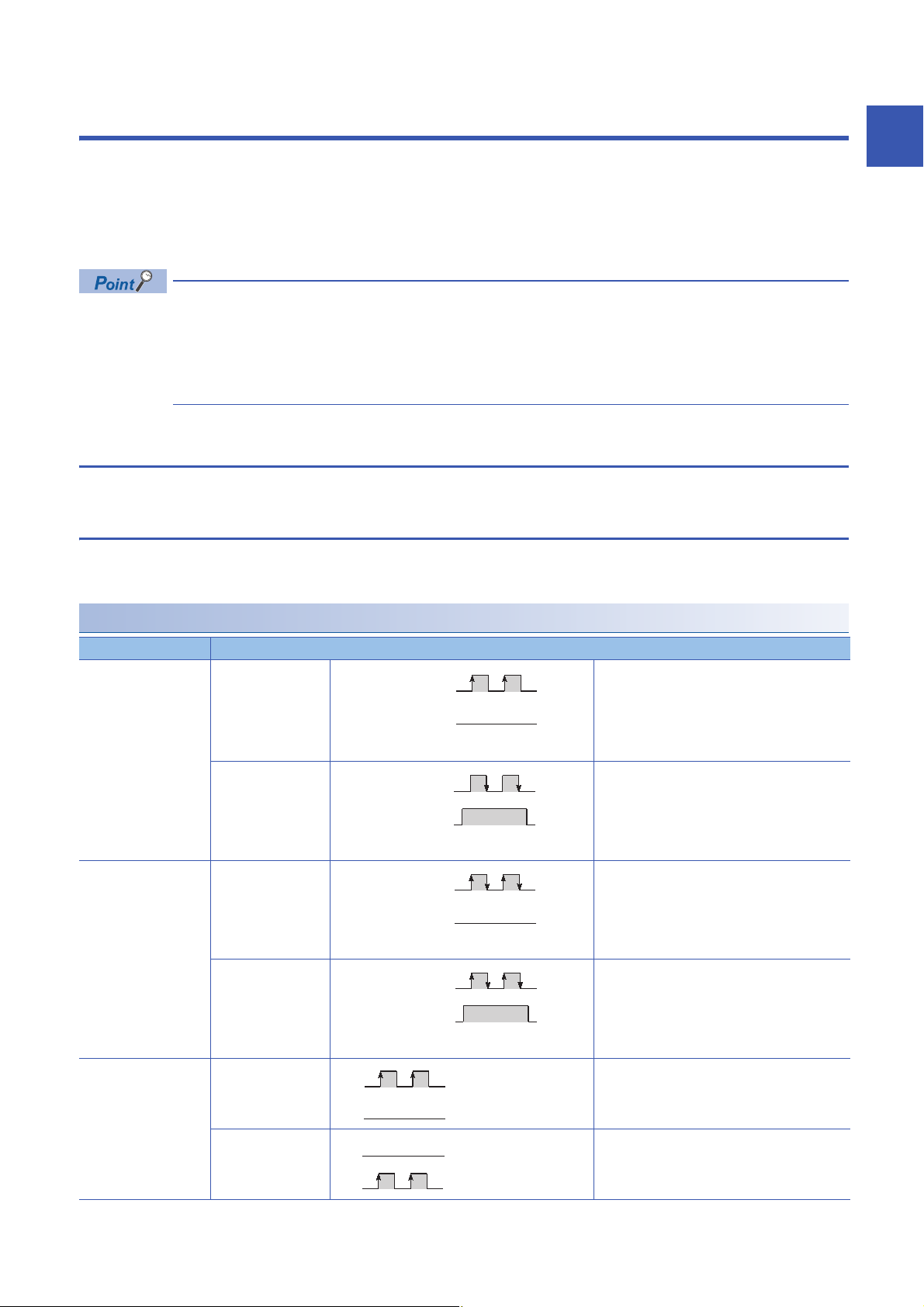
Types of pulse input modes
The following six pulse input modes are prepared: 1-phase pulse input (1 multiple/2 multiples), CW/CCW pulse input, and 2-
phase pulse input (1 multiple/2 multiples/4 multiples).
1
Pulse input modes and count timing
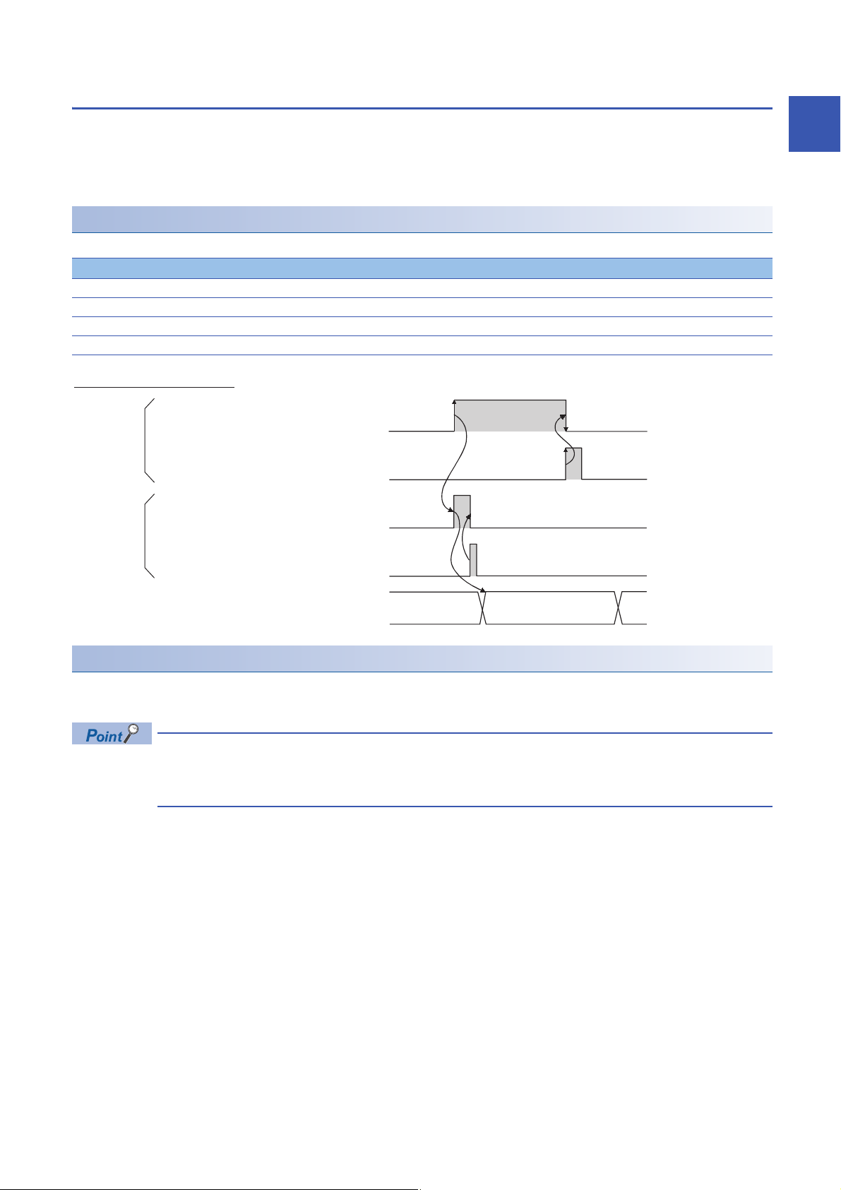
Pulse input mode Count timing
1-phase multiple of 1 For counting up Counts on the rising edge () of A.
count command
For counting down Counts on the falling edge () of A.
count command
1-phase multiple of 2 For counting up Counts on the rising edge () and the falling edge
For counting down Counts on the rising edge () and the falling edge
CW/CCW For counting up Counts on the rising edge () of A.
φB and
CH1 Down
(Y3)
φA
φB or
CH1 Down
(Y3)
φA
B and CH1 Down count command (Y3) are off.
B or CH1 Down count command (Y3) is on.
() of A.
B and CH1 Down count command (Y3) are off.
() of A.
B or CH1 Down count command (Y3) is on.
B is off.
For counting down A is off.
φA
φB
Counts on the rising edge () of B.
1.1 Pulse Input Modes and Counting Methods
1 FUNCTIONS
13
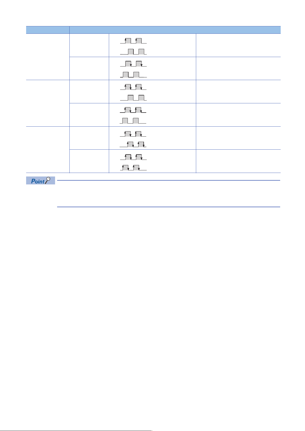
Pulse input mode Count timing
φA
φB
φA
φB
φA
φB
φA
φB
φA
φB
2-phase multiple of 1 For counting up Counts on the rising edge () of A while B is off.
For counting down Counts on the falling edge () of A while B is off.
2-phase multiple of 2 For counting up Counts on the rising edge () of A while B is off.
For counting down Counts on the rising edge () of A while B is on.
2-phase multiple of 4 For counting up Counts on the rising edge () of A while B is off.
For counting down Counts on the rising edge () of A while B is on.
φA
φB
Counts on the falling edge () of A while B is on.
Counts on the falling edge () of A while B is off.
Counts on the falling edge () of A while B is on.
Counts on the rising edge () of B while A is o n.
Counts on the falling edge () of B while A is off.
Counts on the falling edge () of A while B is off.
Counts on the rising edge () of B while A is off.
Counts on the falling edge () of B while A is on .
For the 1-phase pulse input and counting up pulses, check that the B phase pulse input and CH1 Down count
command (Y3) are off before performing the A phase pulse input. If at least one of the B phase pulse input
and CH1 Down count command (Y3) is on, pulses are counted down in the A phase pulse input.
14
1 FUNCTIONS
1.1 Pulse Input Modes and Counting Methods

■1-phase pulse input
φA
φB
Pulse input
Encoder
High-speed counter module
φB or CH1 Down count command
(Y3)
φA
φB
Count-up pulse input
Count-down pulse input
Encoder
Encoder
High-speed counter module
φA
φB
Phase A pulse input
Phase B pulse input
Encoder
High-speed counter module
The count method can be selected from 1 multiple and 2 multiples. The following figure shows the relationship between the A
phase pulse input and B phase pulse input or CH1 Down count command (Y3).
■CW/CCW pulse input
Pulses can be counted up with the A phase pulse input and counted down with the B phase pulse input. The following figure
shows the relationship between the A phase pulse input and B phase pulse input.
1
■2-phase pulse input
The count method can be selected from 1 multiple, 2 multiples, and 4 multiples. The phase difference between the A phase
pulse and B phase pulse determines whether the pulses are counted up or down. The following figure shows the relationship
between the A phase pulse input and B phase pulse input.
1 FUNCTIONS
1.1 Pulse Input Modes and Counting Methods
15

Setting a counting method
Set a counting method in "Basic setting" For details on the setting method, refer to the following.
Page 39 Basic Setting
Reading the present value
This section describes the details on the present value stored in the buffer memory and the count values selected from the
counter function selection, and their reading method.
When the refresh setting is used
By configuring the refresh setting, writing and reading data can be performed without creating a communication program for
the high-speed counter module. For details on the setting method, refer to the following.
Page 43 Refresh Setting
When the refresh setting is not used
■Storage location of the count value
The present value is always stored in CH1 Present value (Un\G2 to Un\G3) regardless of the counter function used.
When the latch counter function, sampling counter function, or cycle pulse counter function is performed, the counter function
selection count value is stored in the corresponding buffer memory addresses listed in the following table besides CH1
Present value (Un\G2 to Un\G3).
Description Present value Counter function selection count value
Buffer memory
address
Latch count
value
Un\G2 to Un\G3 Un\G12 to Un\G13 Un\G14 to Un\G15 Un\G16 to Un\G17 Un\G18 to Un\G19 Un\G24 to Un\G27
Sampling count
value
Cycle pulse
count previous
value
Cycle pulse
count current
value
Cycle pulse
count difference
value
■Stored data
The present value and the counter function selection count values are stored in the buffer memory in 32-bit signed binary.
However, only the cycle pulse count difference value is stored in the buffer memory in 64-bit signed binary. The values in the
buffer memory are automatically updated depending on the count operation.
16
1 FUNCTIONS
1.1 Pulse Input Modes and Counting Methods
1.2 Selecting a Counter Type
+2147483647
-2147483648
Present counter value
Overflow
Overflow
Counting upCounting down
0
Select a counter type in "Counter type" of "Basic setting".
Setting method
1. Set "Counter operation mode" to "Pulse count mode".
2. Set "Counter type" to "Linear counter" or "Ring counter".
Navigation window [Parameter] [Module Information] Module model name [Module Parameter] [Basic
setting]
Item Description Reference
Linear counter This function counts pulses between -2147483648 (lower limit value) and 2147483647
(upper limit value). If a count exceeds the range, the overflow is detected.
Ring counter This function counts pulses repeatedly between the values stored in CH1 Ring counter
lower limit value setting (Un\G20 to Un\G21) and CH1 Ring counter upper limit value
setting (Un\G22 to Un\G23).
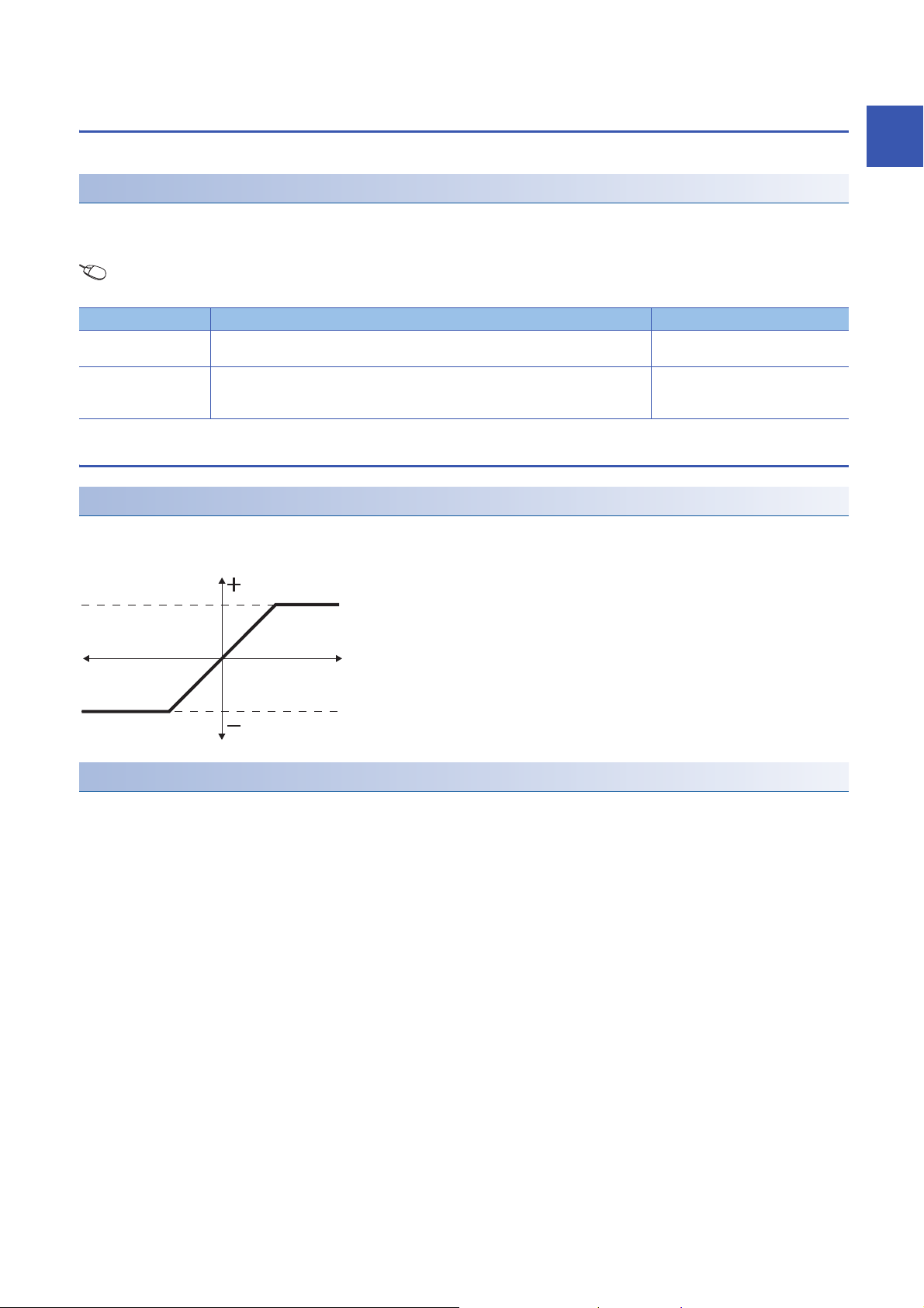
Linear counter function
Operation of the linear counter
• This function counts pulses between -2147483648 (lower limit value) and 2147483647 (upper limit value).
• The preset function and coincidence output function can be used with this function.
Page 17 Linear counter function
Page 18 Ring counter function
1
Overflow error
• When the counter type is the linear counter, an overflow error occurs if the value in CH1 Present value (Un\G2 to Un\G3)
• If an overflow error occurs, 1 is stored in CH1 Overflow detection (Un\G8) and the counting operation stops. The present
• The overflow error can be cleared by performing the preset function.
• When the preset function is performed, 0 is stored in CH1 Overflow detection (Un\G8) and the counting operation restarts.
falls below -2147483648 (lower limit value) at the subtraction or exceeds 2147483647 (upper limit value) at the addition.
value does not change from -2147483648 or 2147483647 even if pulses are input.
1 FUNCTIONS
1.2 Selecting a Counter Type
17
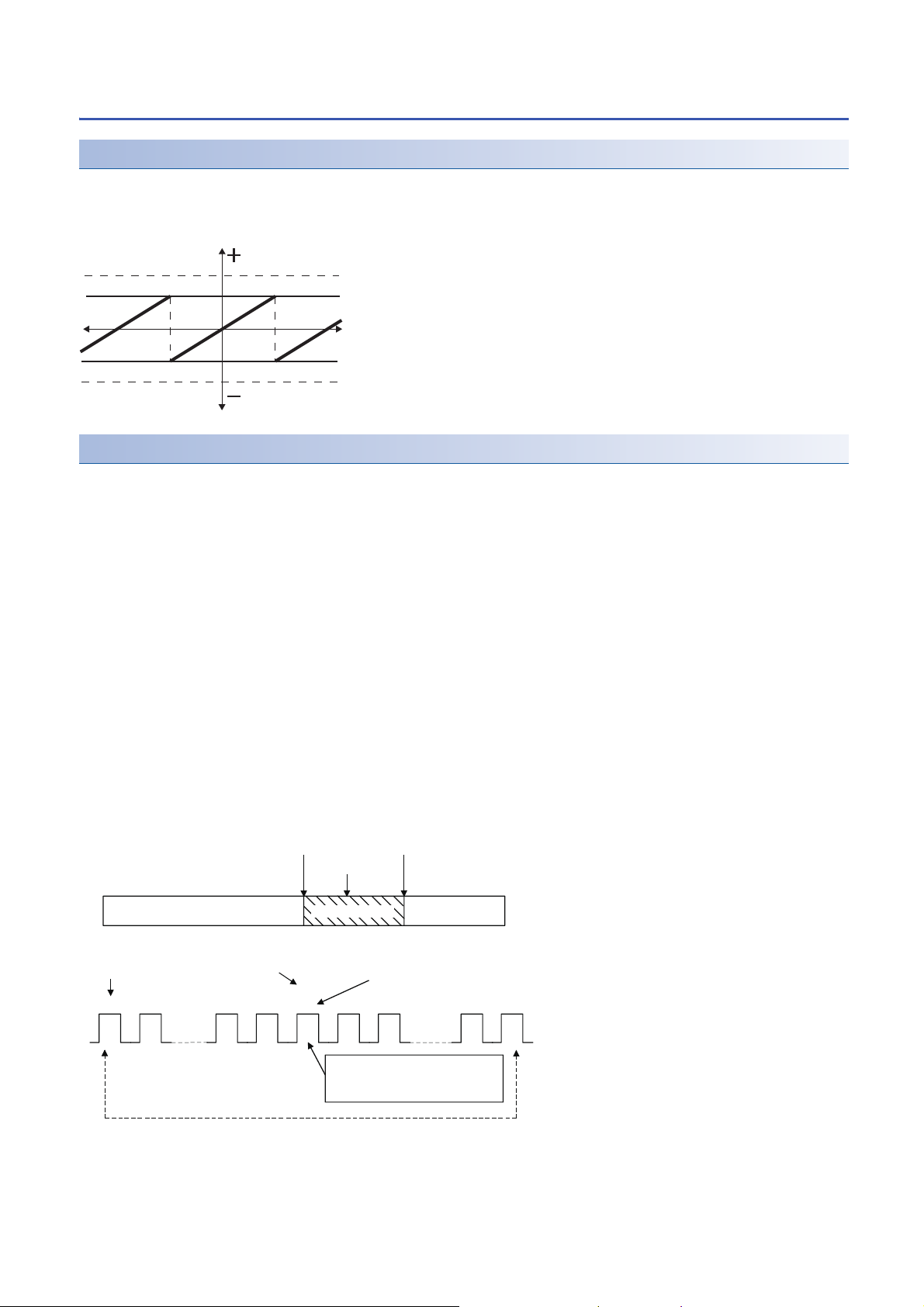
Ring counter function
+2147483647
-2147483648
0
CH1
Ring counter upper limit (Un\G22 to Un\G23)
CH1
Ring counter lower limit (Un\G20 to Un\G21)
Present counter value
Counting up
Counting down
-2147483648
0
500
2000
2147483647
(2000)
500 501 1998 1999 0 1 2 498 499
Ring counter
lower limit value
Present value
Ring counter
upper limit value
Ring counter
lower limit value
to to
Ring counter upper
limit value
The ring counter upper limit value,
2000, is not stored in CH1 Present
value (Un\G2 to Un\G3).
Present value
Counting range
Operation of the ring counter
This function repeatedly counts pulses between the values stored in CH1 Ring counter lower limit value setting (Un\G20 to
Un\G21) and CH1 Ring counter upper limit value setting (Un\G22 to Un\G23). When the ring counter function is selected, an
overflow error does not occur. The preset function and coincidence output function can be used with this function.
Count range of the ring counter
The count range is determined by the relationship between the ring counter lower limit value or ring counter upper limit value
and the value in CH1 Present value (Un\G2 to Un\G3) when CH1 Count enable command (Y4) is turned on or when the
preset function is performed. Normally, the count range is Ring counter lower limit value Present value Ring counter upper
limit value.
■When the count range is Ring counter lower limit value Present value Ring counter upper
limit value (normally used)
• When pulses are counted up, the ring counter lower limit value is automatically stored in CH1 Present value (Un\G2 to
Un\G3) when the present value reaches the ring counter upper limit value.
• When pulses are counted down, even when the present value reaches the ring counter lower limit value, the ring counter
lower limit value is held as the lower limit, and the value of Ring counter upper limit value - 1 is stored in CH1 Present value
(Un\G2 to Un\G3) at the next count-down pulse input.
Both when pulses are counted up and when pulses are counted down, the ring counter upper limit value is not stored in CH1
Present value (Un\G2 to Un\G3). For example, when the count enable command is valid while the ring counter lower limit
value is 0, the ring counter upper limit value is 2000, and the present value is 500, the count range and the present value will
change as follows.
18
1 FUNCTIONS
1.2 Selecting a Counter Type
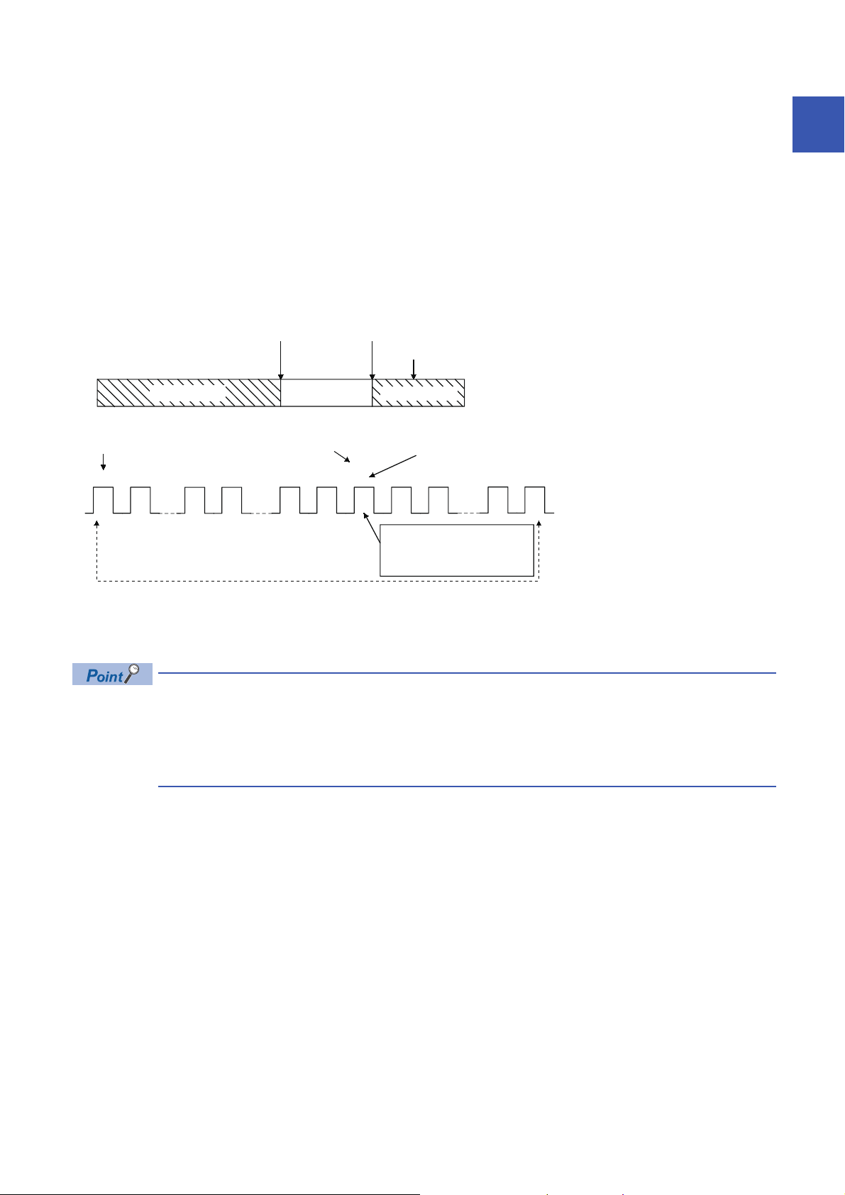
■When the count range is Present value < Ring counter lower limit value or Ring counter upper
-2147483648
0
2000
3000 3001 2001-2 -1 0 2002 29982147483647 -2147483648 2999
(2000)
3000
2147483647
Ring counter
lower limit value
Present value
Ring counter
upper limit value
Ring counter
lower limit value
Ring counter
upper limit valuePresent value
to toto
The ring counter upper limit
value, 2000, is not stored in CH1
Present value (Un\G2 to Un\G3).
Counting range Counting range
limit value < Present value
• When pulses are counted up, even when the present value reaches the ring counter lower limit value, the ring counter
lower limit value is held as the lower limit, and the value of Ring counter upper limit value + 1 is stored in CH1 Present value
(Un\G2 to Un\G3) at the next count-up pulse input.
• When pulses are counted down, the ring counter lower limit value is automatically stored in CH1 Present value (Un\G2 to
Un\G3) when the present value reaches the ring counter upper limit value.
Both when pulses are counted up and when pulses are counted down, the ring counter upper limit value is not stored in CH1
Present value (Un\G2 to Un\G3). For example, when the count enable command is valid while the ring counter lower limit
value is 0, the ring counter upper limit value is 2000, and the present value is 3000, the count range and the present value will
change as follows.
1
■When the count range is Ring counter lower limit value = Ring counter upper limit value
When this condition is established, a value that can be expressed in 32-bit signed binary (-2147483648 to 2147483647) will
be the count range, regardless or the present value.
• While CH1 Count enable command (Y4) is on, even if CH1 Ring counter lower limit value setting (Un\G20 to
Un\G21) and CH1 Ring counter upper limit value setting (Un\G22 to Un\G23) are changed, the high-speed
counter module does not operate with the changed value. Turn off CH1 Count enable command (Y4) before
changing the ring counter upper limit value or ring counter lower limit value.
• Turn off CH1 Count enable command (Y4) before changing the count range using the preset function.
1 FUNCTIONS
1.2 Selecting a Counter Type
19
1.3 Coincidence Output Function
This function compares the present count value with the preset count value, and outputs a signal when they match.
Setting method
1. Set "Counter operation mode" to "Pulse count mode".
2. Set a count value for "Coincidence output point No.1 setting" or "Coincidence output point No.2 setting".
Navigation window [Parameter] [Module Information] Module model name [Module Parameter] [Basic
setting]
Item Setting range
Coincidence output point No.1 -2147483648 to 2147483647
Coincidence output point No.2
Up to two coincidence outputs can be set for each channel.
When the external output of the coincidence signal is used, turn on CH1 Coincidence signal enable command (Y2)
beforehand.
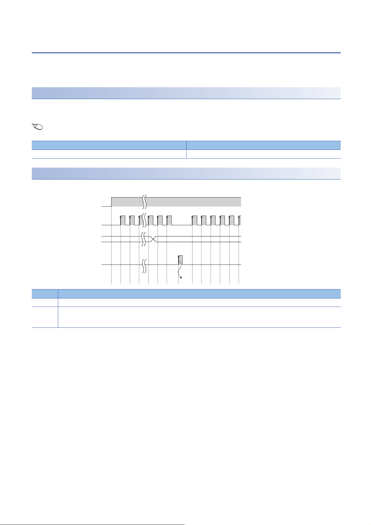
Operation of the coincidence output
CH1 Count enable command (Y4)
CH1 Coincidence signal enable
command (Y2)
Counter input pulse
CH1 Coincidence output point
No.1 setting (Un\G4 to Un\G5)
CH1 Counter value smaller
(point No.1) (X3)
CH1 Counter value coincident
(point No.1) (X2)
Coincidence output point No.1
terminal (EQU1)
CH1 Coincidence signal No.1
reset command (Y0)
CH1 Counter value larger
(point No.1) (X1)
ON
OFF
ON
OFF
H
L
0 100
ON
OFF
ON
OFF
ON
OFF
ON
OFF
ON
OFF
(4)
(1)
(2)
(3)
(5)
(5)
(5)
(6) (7)
(8)
CH1 Present value
(Un\G2 to Un\G3)
0 1 2 98 99 100 101 102 103
·
No. Description
(1) The comparison operation starts with the value set to CH1 Coincidence output point No.1 setting (Un\G4 to Un\G5).
(2) When CH1 Present value (Un\G2 to Un\G3) becomes less than CH1 Coincidence output point No.1 setting (Un\G4 to Un\G5), CH1 Counter
(3) When CH1 Coincidence signal No.1 reset command (Y0) is turned on, CH1 Counter value coincident (point No.1) (X2) and the coincidence
(4) If a coincidence output from the coincidence output point No.1 terminal (EQU1) is required, turn on CH1 Coincidence signal enable command
value smaller (point No.1) (X3) turns on.
output point No.1 terminal (EQU1) turns off.
(Y2).
1 FUNCTIONS
20
1.3 Coincidence Output Function

No. Description
(5) When CH1 Present value (Un\G2 to Un\G3) equals to CH1 Coincidence output point No.1 setting (Un\G4 to Un\G5), CH1 Counter value
coincident (point No.1) (X2) and the coincidence output point No.1 terminal (EQU1) turn on.
Also, CH1 Counter value smaller (point No.1) (X3) turns off.
(6) When CH1 Coincidence signal No.1 reset command (Y0) is turned on while the values match, CH1 Counter value coincident (point No.1) (X2)
and the coincidence output point No.1 terminal (EQU1) turn off.
(7) Even though CH1 Coincidence signal No.1 reset command (Y0) is turned off while the values match, CH1 Counter value coincident (point No.1)
(X2) and the coincidence output point No.1 terminal (EQU1) do not turn on.
(8) When CH1 Present value (Un\G2 to Un\G3) becomes greater than CH1 Coincidence output point No.1 setting (Un\G4 to Un\G5), CH1 Counter
value larger (point No.1) (X1) turns on.
1
1 FUNCTIONS
1.3 Coincidence Output Function
21

Precautions for using the coincidence output function
When CH1 Coincidence signal enable command (Y2) is turned on before the count is started or while the coincidence output
point setting value and the current value match, the coincidence output is performed. To avoid this status, perform one of the
following operations before turning on CH1 Coincidence signal enable command (Y2).
■Setting different values to the coincidence output point setting value and the current value
Set different values to the coincidence output point setting value and the current value by one of the following methods.
• Changing the coincidence output point setting value
• Changing the current value using the preset function
• Changing the current value by inputting a pulse
■Turning off the counter value coincidence signal
Turn on and off CH1 Coincidence signal No.1 reset command (Y0).
• Since CH1 Present value (Un\G2 to Un\G3) and CH1 Coincidence output point No.1 (Un\G4 to Un\G5) are
0 after the CPU module is powered on or is reset, CH1 Counter value coincident (point No.1) (X2) turns on.
• When CH1 Coincidence signal enable command (Y2) is turned on while CH1 Counter value coincident
(point No.1) (X2) is on, the coincidence output is performed to outside the module. To avoid an incorrect
coincidence output, turn on and off CH1 Coincidence signal No.1 reset command (Y0) before turning on
CH1 Coincidence signal enable command (Y2), and turn off CH1 Counter value coincident (point No.1)
(X2).
Precautions for mounting a remote head module
When a high-speed counter module has been mounted with a remote head module, whether to hold or clear the Y signal at a
disconnection of own station can be set with “CPU error output mode setting” in the module parameter. According to this
setting, whether to continue counting and operate the coincidence output, or to stop counting and not to operate the
coincidence output can be specified.
Setting methods when the parameter is set with “CPU error output mode setting” are described as follows.
• Enable the station-based block data assurance for cyclic data in the sending side.
• To hold the PWM output at a disconnection, select “Hold” for “CPU error output mode setting” in the module parameter.
• To stop the PWM output at a disconnection, select “Clear” for “CPU error output mode setting” in the module parameter.
This setting is valid in module units. The parameter cannot be set in each channel.
22
1 FUNCTIONS
1.3 Coincidence Output Function
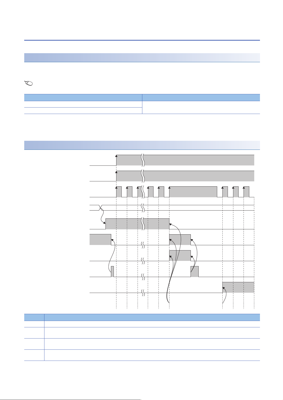
Coincidence detection interrupt function
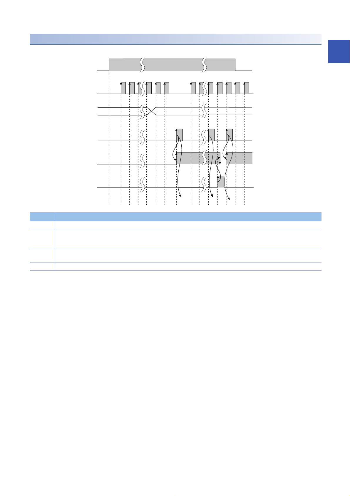
Interrupt program execution timing
I/O signals
Interrupt request
Interrupt request clear
Interrupt program
Internal
processing of
CPU module
CH1 Counter value coincident (point No.1) (X2)
CH1 Counter value coincident (point No.2) (X6)
CH1 Coincidence signal No.1 reset command (Y0)
CH1 Coincidence signal No.2 reset command (Y7)
Program in CPU module
This function outputs an interrupt request to the CPU module and starts an interrupt program when the present counter value
matches with the preset coincidence output point setting value.
For details on the interrupt program, refer to the following.
MELSEC iQ-R CPU Module User's Manual (Application)
Interrupt factor
The high-speed counter module has interrupt factors of 4 points for each coincidence output point.
Interrupt factor
Turning on CH1 Counter value coincident (point No.1) (X2)
Turning on CH1 Counter value coincident (point No.2) (X6)
Turning on CH2 Counter value coincident (point No.1) (X9)
Turning on CH2 Counter value coincident (point No.2) (XD)
1
Setting interrupt pointers
Set interrupt pointers in the parameter settings. For details on the setting method, refer to the following.
Page 42 Interrupt Setting
• A coincidence detection interrupt occurs on the rising edge of the counter value coincidence signal (When
the signal is turned off and on). Therefore, the next interrupt will not be requested unless the coincidence
signal is reset and the counter value coincidence signal is turned off.
1 FUNCTIONS
1.3 Coincidence Output Function
23
1.4 Preset Function
ON
OFF
ON
OFF
101100676665210
1000
(1)
(2)
102 103 104 105
Counter input pulse
CH1 Count enable command
(Y4)
CH1 Preset command
(Y1)
CH1 Present value
(Un\G2 to Un\G3)
CH1 Preset value
(Un\G0 to Un\G1)
to
This function overwrites the present counter value with the set numerical value. The set value is referred to as a preset value.
This function can be used to start counting pulses from the preset value. The function can be performed using a program or
an external control signal.
Setting method
1. Set "Counter operation mode" to "Pulse count mode".
2. Set a preset value to "Preset value setting".
Navigation window [Parameter] [Module Information] Module model name [Module Parameter] [Basic
setting]
Item Setting range
Preset value setting -2147483648 to 2147483647
Performing the preset function using a program
Perform the preset function by turning on CH1 Preset command (Y1) using a program.
No. Description
(1) Write a value into CH1 Preset value setting (Un\G0 to Un\G1) in 32-bit signed binary.
(2) On the rising edge (off and on) of CH1 Preset command (Y1), the value in CH1 Present value (Un\G2 to Un\G3) is replaced with the value in CH1
Preset value setting (Un\G0 to Un\G1).
The preset function can be performed regardless of the on/off status of CH1 Count enable command (Y4).
24
1 FUNCTIONS
1.4 Preset Function
Performing the preset function using an external control signal
ON
OFF
ON
OFF
ON
OFF
ON
OFF
1016665210 130 131 100 10110067
0 100
(1)
(2) (2)
(4)
(3)
toto
CH1 Count enable command
(Y4)
CH1 Preset value
(Un\G0 to Un\G1)
Preset command
(preset input terminal)
CH1 External preset
request detection
(X4)
CH1 External preset
detection reset command
(Y5)
CH1 Present value
(Un\G2 to Un\G3)
Counter input pulse
Perform the preset function by applying an ON voltage to the preset input terminal for external input.
1
No. Description
(1) Write a value into CH1 Preset value setting (Un\G0 to Un\G1) in 32-bit signed binary.
(2) On the rising edge (off and on) of the preset command (A voltage is applied to the preset input terminal), the value in CH1 Present value (Un\G2
(3) Even though a voltage is applied to the preset input terminal while CH1 External preset request detection (X4) is on, the value in CH1 Present
(4) CH1 External preset request detection (X4) is turned off by turning on CH1 External preset detection reset command (Y5).
to Un\G3) is replaced with the value in CH1 Preset value setting (Un\G0 to Un\G1). The preset function can be performed regardless of the on/off
status of CH1 Count enable command (Y4).
value (Un\G2 to Un\G3) is not replaced with the preset value.
1 FUNCTIONS
1.4 Preset Function
25
1.5 Counter Function Selection
The count disable function, latch counter function, sampling counter function, or cycle pulse counter function can be used by
selecting each item in the counter function selection setting of the "Counter function selection setting". The selected counter
function is performed by the counter function selection start command (when CH1 Counter function selection start command
(Y6) is turned on using a program or a voltage is applied to the function start input terminal).
Only one of the four counter functions can be selected from the counter function selection.
Setting method
1. Set "Counter operation mode" to "Pulse count mode".
2. Set the function to be used in "Counter function selection setting".
Navigation window [Parameter] [Module Information] Module model name [Module Parameter] [Application
setting]
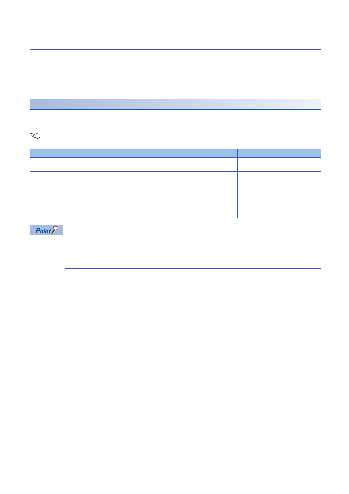
Item Description Reference
Count disable function This function stops counting pulses while CH1 Count enable command
(Y4) is on.
Latch counter function This function latches the present counter value when Counter function
selection start command is input.
Sampling counter function This function counts pulses input during the specified sampling time (T)
and stores the count value in the buffer memory.
Cycle pulse counter function This function stores the current value, previous value, and difference
value of the counter in the buffer memory at every specified cycle time
(T).
Page 28 Count disable function
Page 29 Latch counter function
Page 30 Sampling counter function
Page 31 Cycle pulse counter function
• Change the counter function while CH1 Counter function selection start command (Y6) is off.
• The selected counter function can be performed by turning on CH1 Counter function selection start
command (Y6) or applying a voltage to the function start input terminal. A signal that is input first takes
priority.
26
1 FUNCTIONS
1.5 Counter Function Selection
 Loading...