

Page 1
i-MiEV - ENGLISH - OHAE13E1
OWNER’S MANUAL
i-MiEV
i-MiEV - ENGLISH - OHAE13E1
Page 2
Foreword
Thank you for selecting a i-MiEV as your new vehicle.
owner’s manual will add to your understanding and full enjoyment of
This
the many fine features of this vehicle.
It contains information prepared to acquaint you with the proper way to operate and maintain your vehicle for the utmost in driving pleasure.
MITSUBISHI MOTORS Europe B.V. reserves the right to make changes in
design and specifications and/or to make additions to or improvements in
this product without obligation to install them on products previously manufactured.
It is an absolute requirement for the driver to strictly observe all laws and regulations concerning vehicles.
This owner’s manual has been written in compliance with such laws and regulations, but some of the contents may become contradictory with later amendment of the laws and regulations.
Please leave this owner’s manual in this vehicle at time of resale. The next
owner will appreciate having access to the information contained in this owner’s manual.
Repairs to your vehicle:
Vehicles in the warranty period:
All warranty repairs must be carried out by a MITSUBISHI MOTORS Authorized Service Point.
Vehicles outside the warranty period:
Where the vehicle is repaired is at the discretion of the owner.
E09200104089
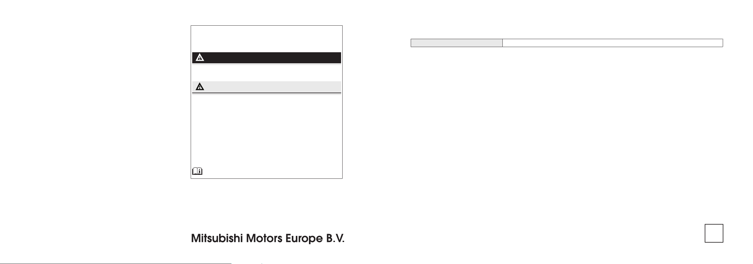
Throughout this owner’s manual the words WARNING and CAUTION ap-
pear.
These serve as reminders to be especially careful. Failure to follow instructions could result in personal injury or damage to your vehicle.
WARNING
indicates a strong possibility of severe personal injury or death if instructions are not followed.
CAUTION
means hazards or unsafe practices that could cause minor personal injury or damage to your vehicle.
You will see another important symbol:
NOTE: gives helpful information.
*: indicates optional equipment.
It may differ according to the sales classification; refer
to the sales catalogue.
Abbreviations used in this owner’s manual:
LHD: Left-Hand Drive
RHD: Right-Hand Drive
The symbol used on the vehicles:
: See owner’s manual
Information for station service
Tyre inflation pressure Refer to the “Vehicle care and Maintenance” section for the tyre inflation pressure.
E09300102480
© 2012 Mitsubishi Motors Corporation
OHAE13E1
BLC12.001744
13
Page 3

Table of contents
OHAE13E1
Overview
General information
Charging 1
Locking and unlocking 2
Seat and seat belts 3
Instruments and controls 4
Starting and driving 5
For pleasant driving 6
For emergencies 7
Vehicle care and Maintenance 8
Specifications 9
Page 4
LHD
Overview
OHAE13E1
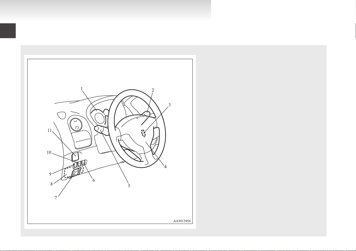
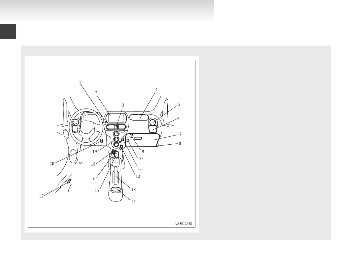
Instruments and Controls (Driver’s area)
1. Instruments p. 4-02
2.
Windscreen wiper and washer switch p. 4-16
Rear window wiper and washer switch p. 4-17
3. Electric motor switch p. 5-07
4. Supplemental restraint system - airbag (for driver's seat) p. 3-20
Horn switch p. 4-19
5. Combination headlamps and dipper switch p. 4-11
Turn-signal lever p. 4-14
Front fog lamp switch* p. 4-15
Rear fog lamp switch p. 4-16
6. Acoustic Vehicle Alerting System (AVAS) OFF switch p. 5-13
7. Regular charging lid opener p. 1-09
8. Fuses p. 8-20
9. Headlamp levelling switch p. 4-13
10. Active Stability Control (ASC) OFF switch p. 5-17
11. Electric remote-controlled outside rear-view mirrors
switch p. 5-05
E00100106409
Page 5
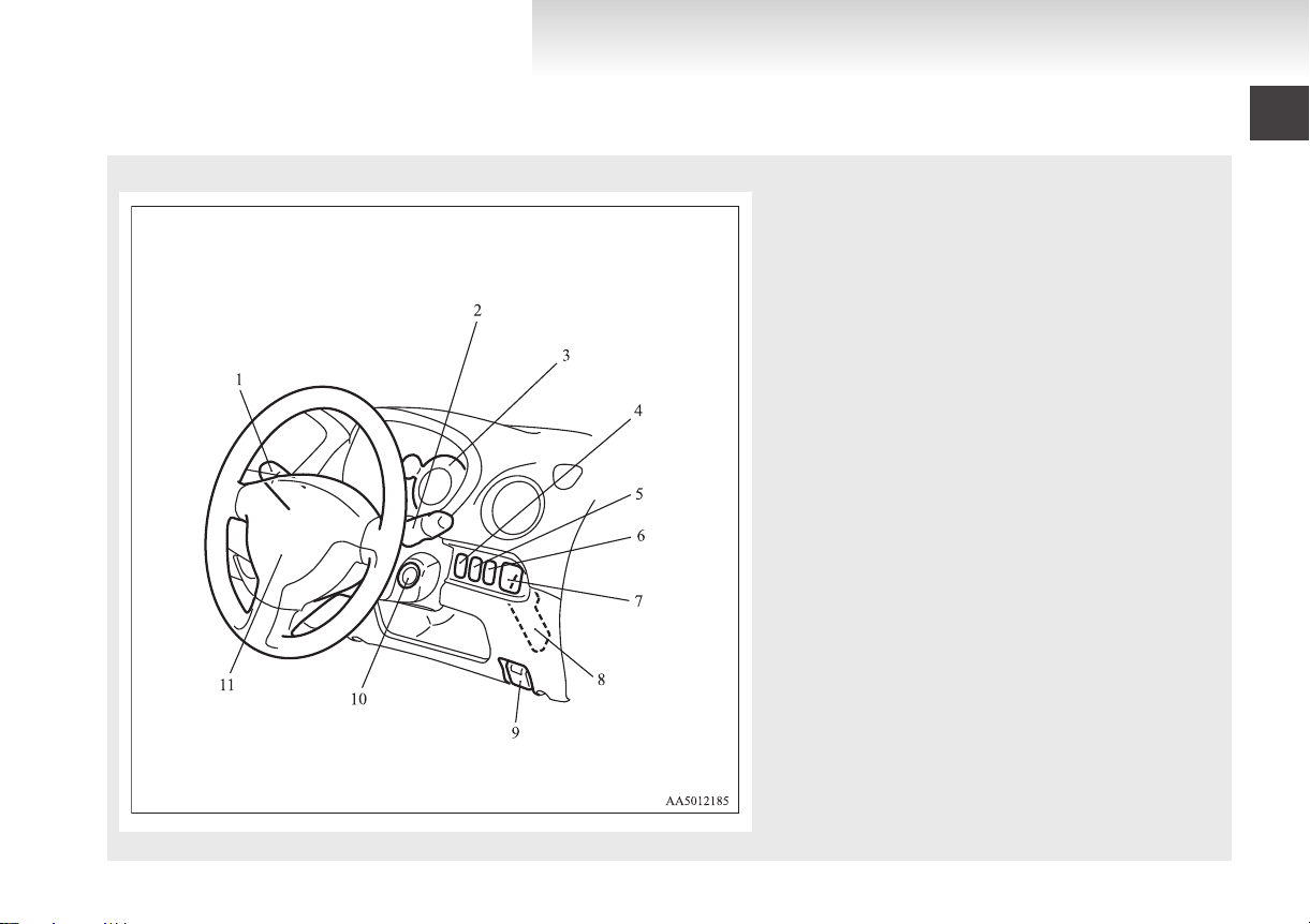
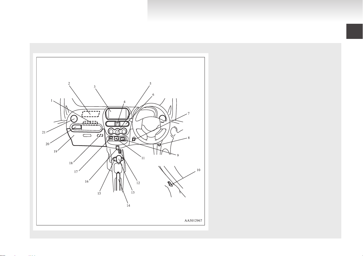
RHD
OHAE13E1
Overview
1. Combination headlamps and dipper switch p. 4-11
Turn-signal lever p. 4-14
Front fog lamp switch* p. 4-15
Rear fog lamp switch p. 4-16
2.
Windscreen wiper and washer switch p. 4-16
Rear window wiper and washer switch p. 4-17
3. Instruments p. 4-02
4. Headlamp levelling switch p. 4-13
5. Active Stability Control (ASC) OFF switch p. 5-19
6. Rear window demister switch p. 4-18
7. Electric remote-controlled outside rear-view mirrors
switch p. 5-05
8. Fuses p. 8-20
9. Regular charging lid opener p. 1-09
10. Electric motor switch p. 5-07
11. Supplemental restraint system - airbag (for driver's seat) p. 3-20
Horn switch p. 4-19
Page 6
LHD
Overview
OHAE13E1
Instruments and Controls (Instrument panel)
1. Centre ventilators p. 6-10
2.
Digital clock* p. 6-31
Audio* p. 6-10
3. Hazard warning flasher switch p. 4-15
4. Supplemental restraint system - airbag (for front passenger) p. 3-20
5. Side ventilators p. 6-02
6. Cup holder p. 6-40
7. Glove box p. 6-39
8. Bonnet release lever p. 8-07
9. Front passenger’s airbag ON-OFF switch p. 3-23
10. Card holder p. 6-39
11. Rear window demister switch p. 4-18
12. Accessory socket p. 6-36
13. Parking brake lever p. 5-03
14. Cup holder p. 6-40
15. Selector lever p. 5-09
16. Heated seat switch p. 3-04
17. Quick charging lid opener p. 1-12
18. USB input terminal* p. 6-33
19. Air conditioning p. 6-03
20. Heated seat switch p. 3-04
E00100106412
Page 7
RHD
OHAE13E1
Overview
1. Secret box p. 6-39
2.
Supplemental restraint system - airbag (for front passenger) p. 3-20
3. Digital clock* p. 6-31
Audio* p. 6-10
4. Hazard warning flasher switch p. 4-15
5. Air conditioning p. 6-03
6. Centre ventilators p. 6-10
7. Heated seat switch p. 3-04
8. Bonnet release lever p. 8-07
9. Acoustic Vehicle Alerting System (AVAS) OFF switch p. 5-13
10. Quick charging lid opener p. 1-12
11. Front passenger’s airbag ON-OFF switch p. 3-23
12. Heated seat switch p. 3-04
13. Selector lever p. 5-09
14. Parking brake lever p. 5-03
15. Cup holder p. 6-40
16. Accessory socket p. 6-36
17. USB input terminal* p. 6-33
18. Card holder p. 6-39
19. Glove box p. 6-39
20. Cup holder p. 6-40
21. Side ventilators p. 6-02
Page 8
LHD
Overview
OHAE13E1
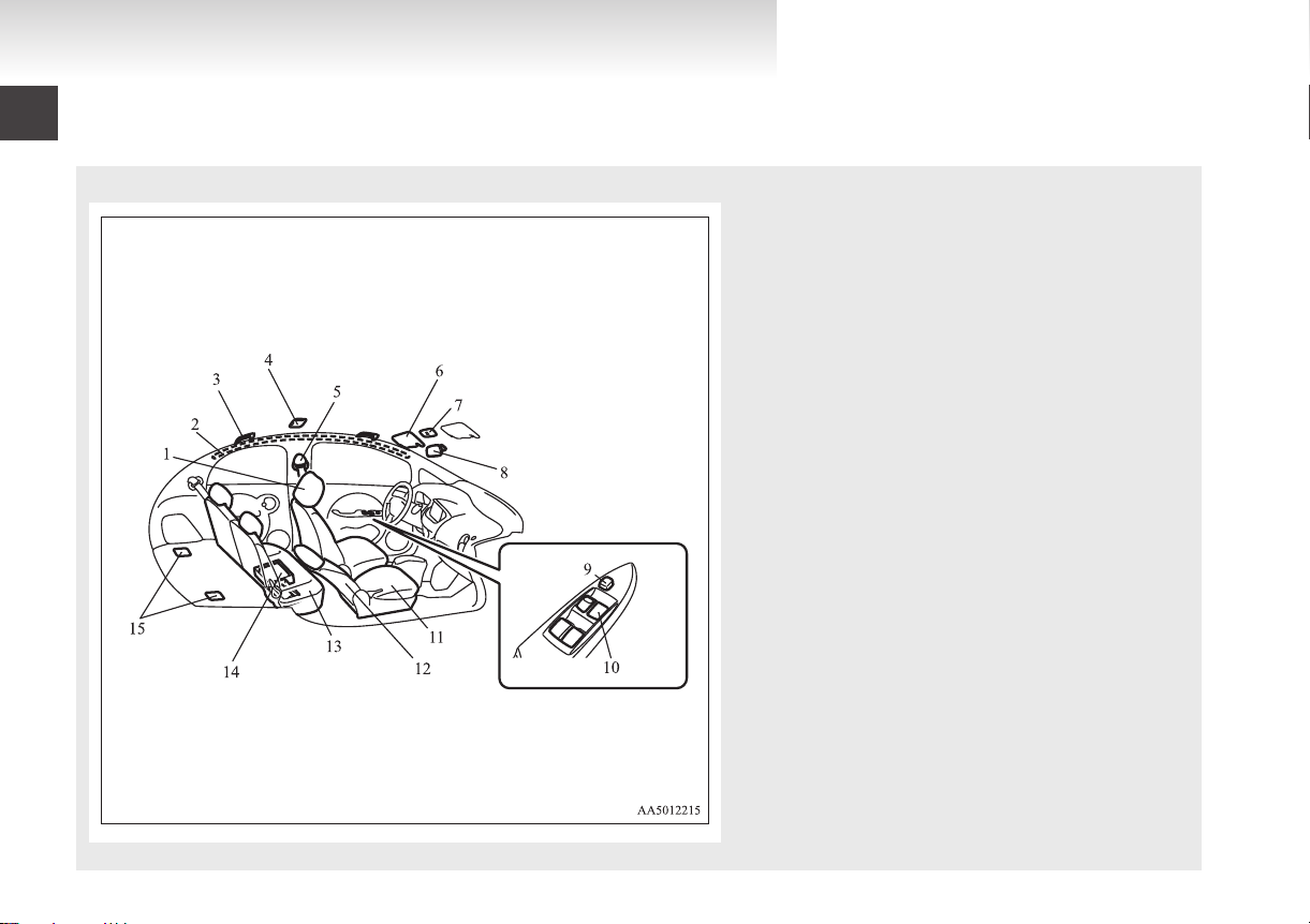
Interior
1. Head restraints p. 3-07
2.
Supplemental restraint system - curtain airbag p. 3-27
3. Assist grip p. 6-41
4. Room lamp (rear) p. 6-38, 8-24
5. Seat belts p. 3-08
6. Sun visor p. 6-35
Vanity mirror p. 6-35
Card holder p. 6-36
7. Map & room lamps (front) p. 6-37, 8-24
8. Inside rear-view mirror p. 5-05
9. Electric window lock switch p. 2-10
10. Electric window control switch p. 2-09
11. Front seat p. 3-03
12. Supplemental restraint system - side airbag (for front
seats) p. 3-27
13. Rear seat* p. 3-05
14. Tyre repair kit p. 7-04
15. Tether anchorages for child restraint system p. 3-18
E00100204536
Page 9
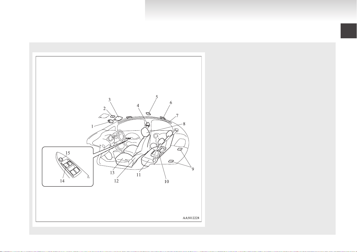
RHD
OHAE13E1
1. Inside rear-view mirror p. 5-05
2.
Map & room lamps (front) p. 6-37, 8-24
3. Sun visor p. 6-35
Vanity mirror p. 6-35
Card holder p. 6-36
4. Seat belts p. 3-08
5. Room lamp (rear) p. 6-38, 8-24
6. Assist grip p. 6-41
7. Supplemental restraint system - curtain airbag p. 3-27
8. Head restraints p. 3-07
9. Tether anchorages for child restraint system p. 3-18
10. Tyre repair kit p. 7-04
11. Rear seat* p. 3-05
12. Supplemental restraint system - side airbag (for front
seats) p. 3-27
13. Front seat p. 3-03
14. Electric window control switch p. 2-09
15. Electric window lock switch p. 2-10
Overview
Page 10
Bonnet room
Electric motor unit room (under the floor of the luggage area)
LHD RHD
Overview
OHAE13E1
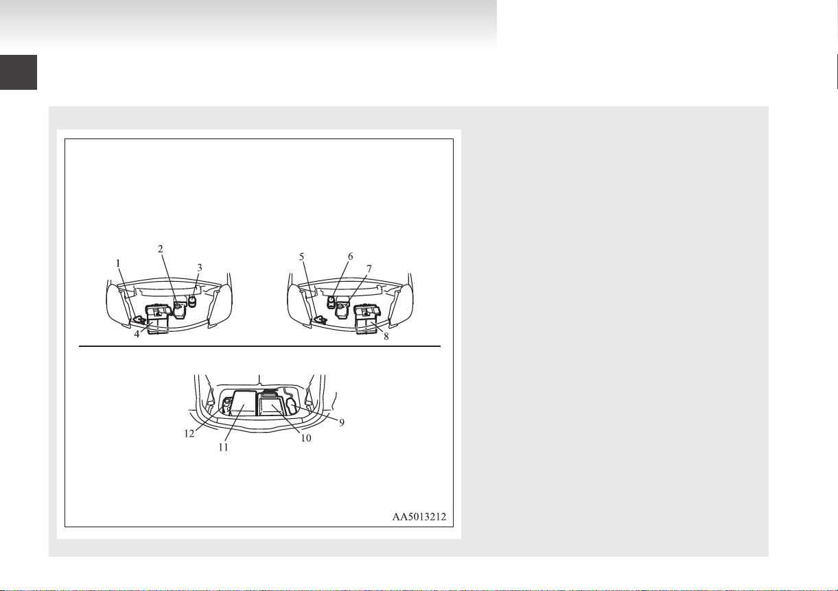
Bonnet room/Electric motor unit room
1. Washer fluid reservoir p. 8-11
2.
Hot water heater reservoir p. 8-09
3. Brake fluid reservoir p. 8-11
4. Auxiliary battery p. 8-12
5. Washer fluid reservoir p. 8-11
6. Brake fluid reservoir p. 8-11
7. Hot water heater reservoir p. 8-09
8. Auxiliary battery p. 8-12
9. Brake electric vacuum pump
10. Inverter p. 8-06
11. On board charger/DC-DC converter p. 8-06
12. Coolant reservoir p. 8-09
E00100800026
Page 11
Overview
OHAE13E1
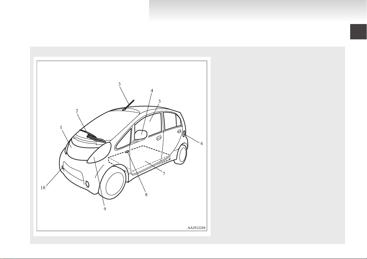
Outside (Front)
E00100504887
1. Bonnet p. 8-07
2.
Windscreen wipers p. 4-16
3. Antenna p. 6-30
4. Outside rear-view mirror p. 5-05
5. Electric window control p. 2-09
6. Quick charging lid p. 1-12
7. Traction battery p. 8-06
8. Side turn-signal lamps/Hazard warning lamps p. 4-09, 8-24, 8-30
9. Headlamps p. 4-11, 8-24, 8-24, 8-28, 8-29
Position lamps p. 4-11, 8-24, 8-24, 8-30
Front turn-signal lamps/Hazard warning lamps p. 4-09, 8-24, 8-24,
8-30
10. Front fog lamps* p. 4-15, 8-24, 8-31
Daytime running lamps* p. 4-13, 8-24, 8-31
Page 12
Overview
OHAE13E1
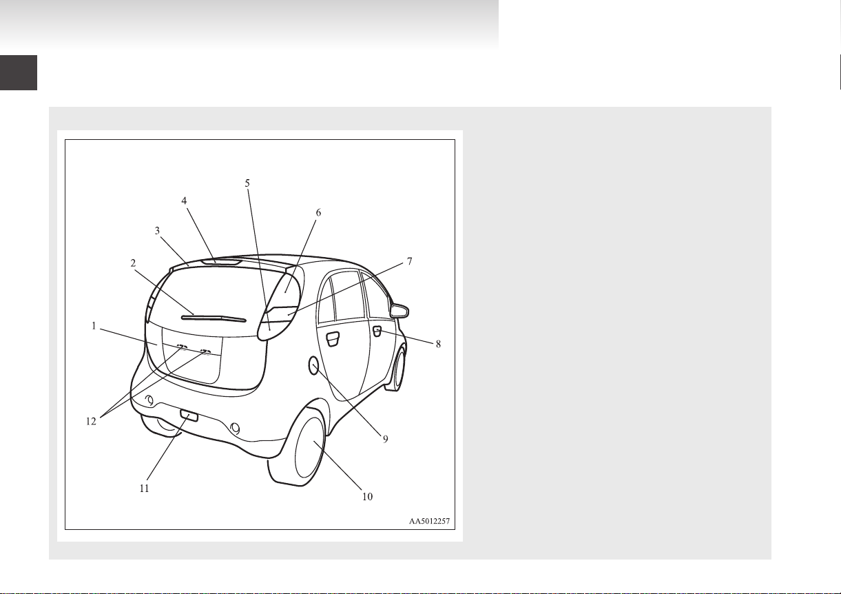
Outside (Rear)
E00100504702
1. Tailgate p. 2-08
2.
Rear window wiper p. 4-17
3. Rear spoiler
4. High-mounted stop lamp p. 8-24, 8-34
5. Reversing lamps p. 8-24, 8-33
6. Stop lamps/Tail lamps p. 4-14, 8-24, 8-33
7. Turn-signal lamps/Hazard warning lamps p. 4-14, 4-15, 8-24, 8-33
8. Keyless entry system p. 2-03
Locking and unlocking the doors p. 2-05
9. Regular charging lid p. 1-09
10. Tyre inflation pressures p. 8-15
Tyre rotation p. 8-16
Tyre chains p. 8-17
Size of tyres and wheels p. 9-06
11. Rear fog lamp p. 4-16, 8-24, 8-32
12. Licence plate lamps p. 4-11, 8-24, 8-34
Page 13

General information
OHAE13E1
Familiarizing yourself with i-MiEV................................................02
Installation of accessories................................................................04
Modification/alterations to the electrical systems
Genuine parts...................................................................................05
Disposal information for used batteries...........................................05
Cautions and actions to deal with intense heat................................06
Cautions and actions to deal with intense cold................................08
............................05
Page 14

General information
OHAE13E1
Familiarizing yourself with
i-MiEV
section describes features that the i-MiEV has
This
as an electric vehicle and gives precautions that
you should observe. It is important. Please read it
carefully.
Main features
Energy
l
l
l
l
l
l
l
required for driving is only electricity and fuel supply is not required.
The traction battery and electric motor unit
are mounted outside the passenger compartment. In this way, passenger space is obtained for riding of four adults.
With the high performance motor, noise and
vibration during driving are greatly limited
and powerful acceleration can also be obtained.
With regenerative braking, the traction battery is automatically charged when the accelerator is released.
The vehicle can be charged from general power outlets (rated AC 220-240 V).
Charge with the quick charger for i-MiEV is
also available.
The creeping behaviour occurs in i-MiEV
like a vehicle with automatic transmission.
E00202600016
E00202700059
WARNING
Always pay special attention to pedes-
l
trians.
Even if the Acoustic Vehicle Alerting System (AVAS) sounds, pedestrians may not
notice your vehicle. Refer to “Acoustic Vehicle Alerting System (AVAS)” on page
5-12.
Regenerative braking
It is equivalent to engine braking of an engine vehi-
If you step off the accelerator pedal during driv-
cle.
ing, motion energy is converted into electric energy
using the motor as a power generator.
In this conversion, braking force is generated and
converted electric energy is charged in the traction
battery.
Regenerative braking is stronger in the order of the
selector lever position of “C” (COMFORT), “D”
(DRIVE), “B” (BRAKE).
Put the selector lever to the “B” (BRAKE) or “C”
(COMFORT) position according to the driving condition.
“B”: Strong regenerative braking (For downhill)
“C”: Weak regenerative braking (For long cruising)
NOTE
If a problem occurs in the electric motor unit,
l
or if the ABS and/or the ASC have been activated, the regenerative braking will be restricted. The foot brake will still operate.
Traction battery
WARNING
sealed lithium ion high voltage battery
A
l
is adopted for i-MiEV. If the lithium ion
battery is improperly disposed of, there is
a risk of severe burns and electrical
shock that may result in serious injury or
death and there is also a risk of environmental damage.
Never attempt to use the traction battery
l
for any other purpose.
It
is the battery to operate the motor (electric
l
motor unit) and the air conditioning.
In addition to the traction battery, i-MiEV
has the auxiliary battery to operate lamps, wipers, etc.
Compact, light-weight lithium ion battery
l
with high energy density is used for the traction battery.
The lithium ion battery has the following char-
l
acteristics. Please read this carefully and
treat the battery paying attention to the following:
E00202800050
02
Page 15
General information
OHAE13E1
Characteristics
The capacity of the lithium-ion battery used
l
as traction battery on your i-MiEV, like other
commonly used lithium ion batteries, will decrease according to time and usage. This
type of decrease in battery capacity is normal, and is not indicative of any defect or failure in your traction battery. As the traction
battery capacity decreases, the initial cruising range of the vehicle will similarly decrease.
MITSUBISHI MOTORS estimates that after
l
5 years, the capacity of the traction battery
provided with your vehicle will be approximately 80% of the original capacity. After 10
years, the capacity should be approximately
70% of the original capacity. These are only
estimates, and the actual capacity of your vehicle battery over time will depend on a variety of factors including how your vehicle is
used, stored and charged. Factors that can adversely affect battery capacity over time include frequent driving, using aggressive acceleration/deceleration, repeated frequent use
of the quick charger, and operation/storage in
extreme hot temperature environments.
The performance may be changed due to the
l
outside temperature. At low temperature, in
particular, the cruising range is short and the
charging time is long, compared to operation
at normal temperature.
The battery discharges over time and the en-
l
ergy level slowly decreases even while not in
use.
It is not necessary to consume the battery com-
l
pletely before charging.
Precautions for operation
Do not store your vehicle with the energy lev-
l
el gauge showing 0 bars.
Doing so could damage the traction battery.
The battery may have to be replaced depending on the low capacity.
If you do not use your vehicle for a long
l
time, please charge the traction battery to the
full every 3 months so that the energy level
gauge may not be 0 bars.
MITSUBISHI MOTORS collects traction bat-
l
teries. If you scrap your vehicle, please consult a MITSUBISHI MOTORS Authorized
Service Point.
NOTE
The progress of the battery capacity loss de-
l
pends on the vehicle usage and the environment.
We recommend to do regular charging from
2 bars or less to charge completely at least
once in 3 months.
The procedure lets the battery remaining indicator adjusted automatically.
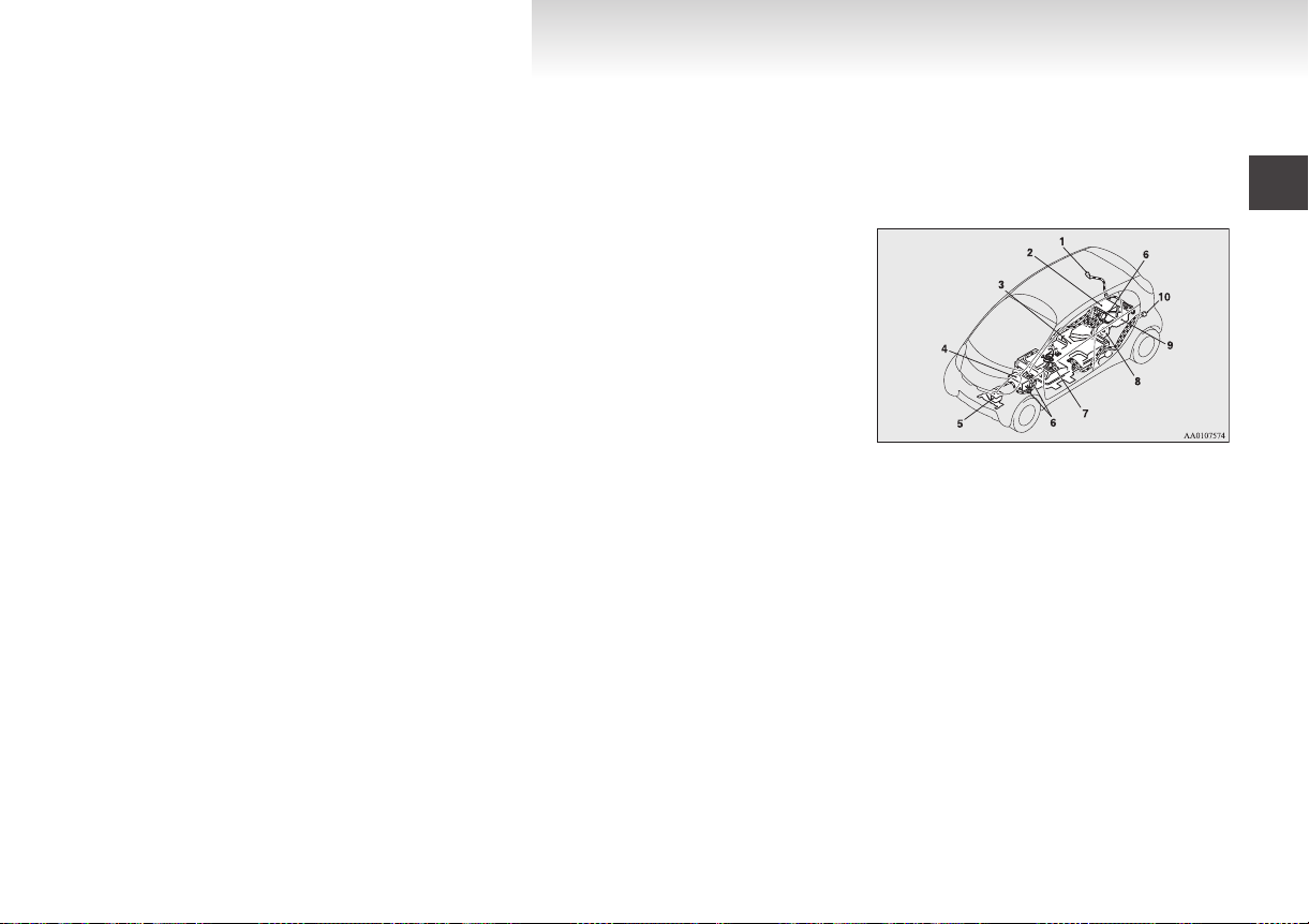
High-Voltage components
High
voltage components and wiring cables are located as shown in the figure below. For detailed information, refer to “Service precautions” on page
8-06.
1- Regular charge port
2-
Inverter
3- Traction battery
4- Heater
5- Air conditioner compressor
6- High voltage connector
7- Service plug
8- Electric motor (Electric motor unit)
9- On board charger/DC-DC converter
10- Quick charge port
Cruising range
Even
if the charge level is the same, the cruis-
l
ing range may vary depending on the driving
conditions. Since driving at high speed or
climbing on a hill requires higher consump-
tion of the traction battery than usual, the
cruising range is shortened.
E00203300010
E00202900019
03
Page 16

General information
OHAE13E1
the air conditioning (cooling or heat-
Since
l
ing) consumes power of the traction battery,
its operation results in a shorter cruising
range. Maintain an appropriate temperature.
Put the selector lever to the “B” (BRAKE) or
l
“C” (COMFORT) position according to the
road condition. To charge the traction battery
with appropriate use of regenerative braking
can increase the cruising range.
Installation of accessories
recommend you to consult a MITSUBISHI
We
MOTORS Authorized Service Point.
The installation of accessories, optional
l
parts, etc., should only be carried out within
the limits prescribed by law in your country,
and in accordance with the guidelines and
warnings contained within the documents accompanying this vehicle.
Installing electric components incorrectly
l
could lead to a fire. See the “Modification/alterations to the electrical systems” section
within this owner’s manual.
Using a cellular phone or radio set inside the
l
vehicle without an external antenna may
cause electrical system interference, which
could lead to unsafe vehicle operation.
Tyres and wheels which do not meet specifi-
l
cations must not be used.
Refer to the “Specifications” section for information regarding wheel and tyre sizes.
E00200301003
Important points!
Due to large number of accessory and replacement
parts of different manufactures available in the market, it is not possible, not only for MITSUBISHI
MOTORS, but also for a MITSUBISHI MOTORS
Authorized Service Point, to check whether the attachment or installation of such parts affects the
overall safety of your MITSUBISHI-vehicle.
Even when such parts are officially authorized, for
example
praisal for the part) or through the execution of the
part in an officially approved manner of construction, or when a single operation permit following
the attachment or installation of such parts, it cannot be deduced from that alone, that the driving safety of your vehicle has not been affected.
Consider also that there basically exists no liability
on the part of the appraiser or the official. Maximum safety can only be ensured with parts recommended, sold and fitted or installed by a
MITSUBISHI MOTORS authorized Service Point
(MITSUBISHI MOTORS genuine replacement
parts and MITSUBISHI MOTORS accessories).
The same also pertains to modifications of
MITSUBISHI vehicles with respect to the production specifications. For safety reasons, do not attempt any modifications other than those that follow the recommendations of a MITSUBISHI
MOTORS authorized Service Point.
by a “general operators permit” (an ap-
04
Page 17
General information
OHAE13E1
Modification/alterations to the
electrical systems
MITSUBISHI MOTORS
ways manufactured safe, high quality vehicles. In
order to maintain this safety and quality, it is important that any accessory that is to be fitted, or any
modifications carried out which involve the electrical systems, should be carried out in accordance
with MITSUBISHI guidelines.
CORPORATION has al-
E00200400456
CAUTION
the wires interfere with the vehicle
If
l
body or improper installation methods
are used (protective fuses not included,
etc.), electronic devices may be adversely
affected, resulting in a fire or other accident.
Genuine parts
MITSUBISHI MOTORS has gone to great lengths
to bring you a superbly crafted automobile offering
the highest quality and dependability.
Use MITSUBISHI MOTORS Genuine Parts, designed and manufactured to maintain your
MITSUBISHI MOTORS automobile at top performance. MITSUBISHI MOTORS Genuine Parts
are identified by this mark and are available at all
MITSUBISHI MOTORS Authorized Service
Points.
E00200500499
Disposal information for used
batteries
Your vehicle contains batteries
and/or accumulators.
Do
not mix with general household waste.
For proper treatment, recovery
and recycling of used batteries,
please take them to applicable collection points, in accordance
with your national legislation
and the Directives 2006/66/EC.
MITSUBISHI MOTORS collects traction batteries. If you
scrap your vehicle, please consult a MITSUBISHI MOTORS
Authorized Service Point.
By disposing of these batteries
correctly, you will help to save
valuable resources and prevent
any potential negative effects on
human health and the environment which could otherwise
arise from inappropriate waste
handling.
E00201300045
05
Page 18

General information
OHAE13E1
Cautions and actions to deal with intense heat
the vehicle is driven in a high ambient temperature, its air-conditioner performance can be insufficient. Also, using the air conditioner can reduce the
When
l
vehicle’s cruising range.
When the ambient temperature is approximately 40 °C or higher, the phenomena described below may occur. Please take the described action.
l
Even if the ambient temperature is approximately 40 °C or lower, the phenomena described below may occur. Please take the described actions.
l
Approx. ambient tem-
perature
Approx. 40 °C or high-
er
Approx. 45 °C or high-
er
Startup and driving
Charging and battery
Startup and driving
Charging and battery
During
l
uphill driving, the power down warning lamp* comes on and
the motor output is restricted to protect the traction battery or motor (electric motor unit).
Regenerative braking performance may decrease.
l
If you continue driving after the power down warning lamp*
l
has come on, the vehicle may stop when you have driven a few
kilometres.
During quick charging, charging times get longer.
l
During
l
uphill driving, the power down warning lamp* comes on and
the motor output is restricted to protect the traction battery or motor (electric motor unit).
Regenerative braking performance may decrease.
l
If you continue driving after the power down warning lamp*
l
has come on, the vehicle may stop when you have driven a few
kilometres.
The EV charging cable (regular charging cable) cannot be used.
l
During quick charging, charging times get longer.
l
The traction battery capacity decreases more quickly, and the
l
cruising range decreases more quickly.
Phenomena Corrective action
quick charging, repeated high-speed driving, or repeated
Stop the vehicle for a while,
l
avoid quick charging, and wait
for the power down warning
lamp* to go off.
quick charging, repeated high-speed driving, or repeated
Stop the vehicle for a while,
l
avoid quick charging, and wait
for the power down warning
lamp* to go off.
Park in a well-ventilated, shady
l
place.
E00203000046
06
Page 19

General information
OHAE13E1
Approx. ambient tem-
perature
Approx. 60 °C or high-
er
Startup and driving
Charging and battery
NOTE
*: Refer to “Power down warning lamp” on page
l
Phenomena Corrective action
power down warning lamp* comes on, and the vehicle may
The
l
stop.
The EV charging cable (regular charging cable) cannot be used.
l
Quick charging may become impossible.
l
4-11. Illumination of the power down warning lamp does not indicate a malfunction.
Park in a well-ventilated, shady
l
place, avoid quick charging, and
wait for the power down warning lamp* to go off.
Park in a well-ventilated, shady
l
place.
07
Page 20

General information
OHAE13E1
Cautions and actions to deal with intense cold
the vehicle is driven in a low ambient temperature, its heater performance can be insufficient. Also, using the heater can reduce the vehicle’s cruising
When
l
range.
When the ambient temperature is approximately -15 °C or lower, the phenomena described below may occur. Please take the described corrective action.
l
Approx. ambient
temperature
Approx. -15 °C or
lower
Startup and driving
Charging and battery
Motor
l
may come on.
<Reference: When the traction battery temperature is -15 °C or
lower and the traction battery’s remaining power is 50 %, the driving performance may decrease by approximately 30 %>
Regenerative braking performance may decrease.
l
Charging times get longer.
l
Complete charging may not be possible.
l
Phenomena Corrective action
1
output is restricted, and the power down warning lamp*
Keep driving if you can drive the
l
same speed as surrounding vehicles. If you cannot drive the same
speed as surrounding vehicles, stop
the vehicle in a safe place and
charge the traction battery or drive
carefully safely surrounding vehicles.
When braking, depress the brake
l
pedal more strongly
When you have finished driving,
l
charge the traction battery before
its temperature falls.
E00203100050
08
Page 21

General information
OHAE13E1
Approx. ambient
temperature
Startup and driving
Approx. -25 °C or
lower
Charging and battery
Startup and driving
Approx. -30 °C or
lower
Charging and battery
CAUTION
If the outside temperature is
l
the vehicle to a warm location.
Phenomena Corrective action
1
output is restricted, and the power down warning lamp*
Motor
l
may come on.
<Reference: When the traction battery temperature is -25 °C or
lower and the traction battery’s remaining power is 50 %, the driving performance may decrease by approximately 50 %>
Regenerative braking performance may decrease.
l
Charging may become impossible.
l
ready indicator*2 does not come on, and startup may not be
The
l
possible.
In the worst-case scenario, the vehicle may become undrivable
l
(with the energy level gauge and cruising range indications still
shown).
Regenerative braking performance may decrease.
l
Charging may become impossible.
l
-25 °C or less, the lithium ion battery may freeze and it cannot be charged or provide power to drive the vehicle. Move
Keep driving if you can drive the
l
same speed as surrounding vehicles. If you cannot drive the same
speed as surrounding vehicles, stop
the vehicle in a safe place and
charge the traction battery or drive
carefully safely surrounding vehicles.
When braking, depress the brake
l
pedal more strongly.
When
l
l
l
l
you have finished driving,
charge the traction battery before
its temperature falls.
the daytime, wait for the temper-
In
ature to rise. When the temperature
in the vicinity of the traction battery has risen, start up.
braking, depress the brake
When
pedal more strongly
In the daytime, wait for the temperature to rise. When the temperature
in the vicinity of the traction battery has risen, begin charging.
09
Page 22

General information
OHAE13E1
NOTE
*1: Refer to “Power down warning lamp” on page
l
*2: Refer to “Ready indicator” on page 4-09.
l
4-11. Illumination of the power down warning lamp does not indicate a malfunction.
10
Page 23

Charging
OHAE13E1
Charging.......................................................................................1-02
Battery..........................................................................................1-04
Basic knowledge for charging......................................................1-04
EV charging cable*......................................................................1-05
Regular charging (charging method with rated AC
220-240 V outlet).....................................................................1-08
Quick charging (charging method with quick charger)................1-12
Charging troubleshooting guide...................................................1-16
MiEV Remote System*................................................................1-18
1
Page 24
Charging
OHAE13E1
Charging
vehicle is equipped with a charge port and a charging cable (EV charging cable)*1 for charging with a AC 220-240V outlet. You can also charge your vehicle
Your
using 220-240V home or public charging device (EVSE*2) compatible with i-MiEV.
Additionally your vehicle is equipped with another charge port for quick charging capable for CHAdeMO quick charger.
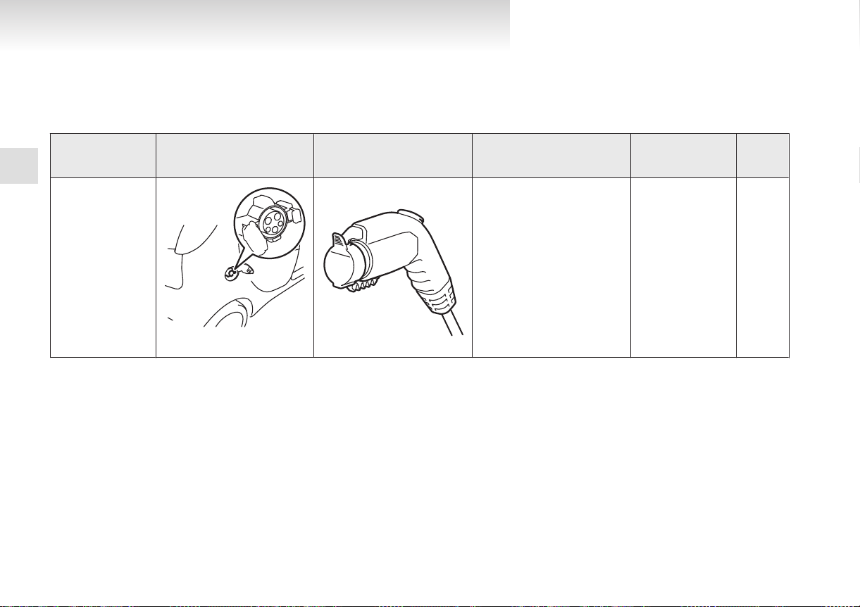
Category Charge port Charge connector Charging Source
1
Regular charging
(AC 220-240V)
When using a genu-
ine charging cable
Right rear side of vehicle
*1
: optional equipment
*2
: EVSE = Electric Vehicle Supply Equipment
*3
: Use this time as a guide because the rated AC voltage and the rated current value may differ from country to country.
220-240V household outlet (Re-
fer to “Charging from rated AC
220-240 V outlet” on page 1-09)
Charging time with
fully discharged bat-
tery
230V/10A: About 8
hours
*3
230V/8A: About 10
hours
*3
E08303800025
Reference
p. 1-08
1-02
Page 25
Charging
OHAE13E1
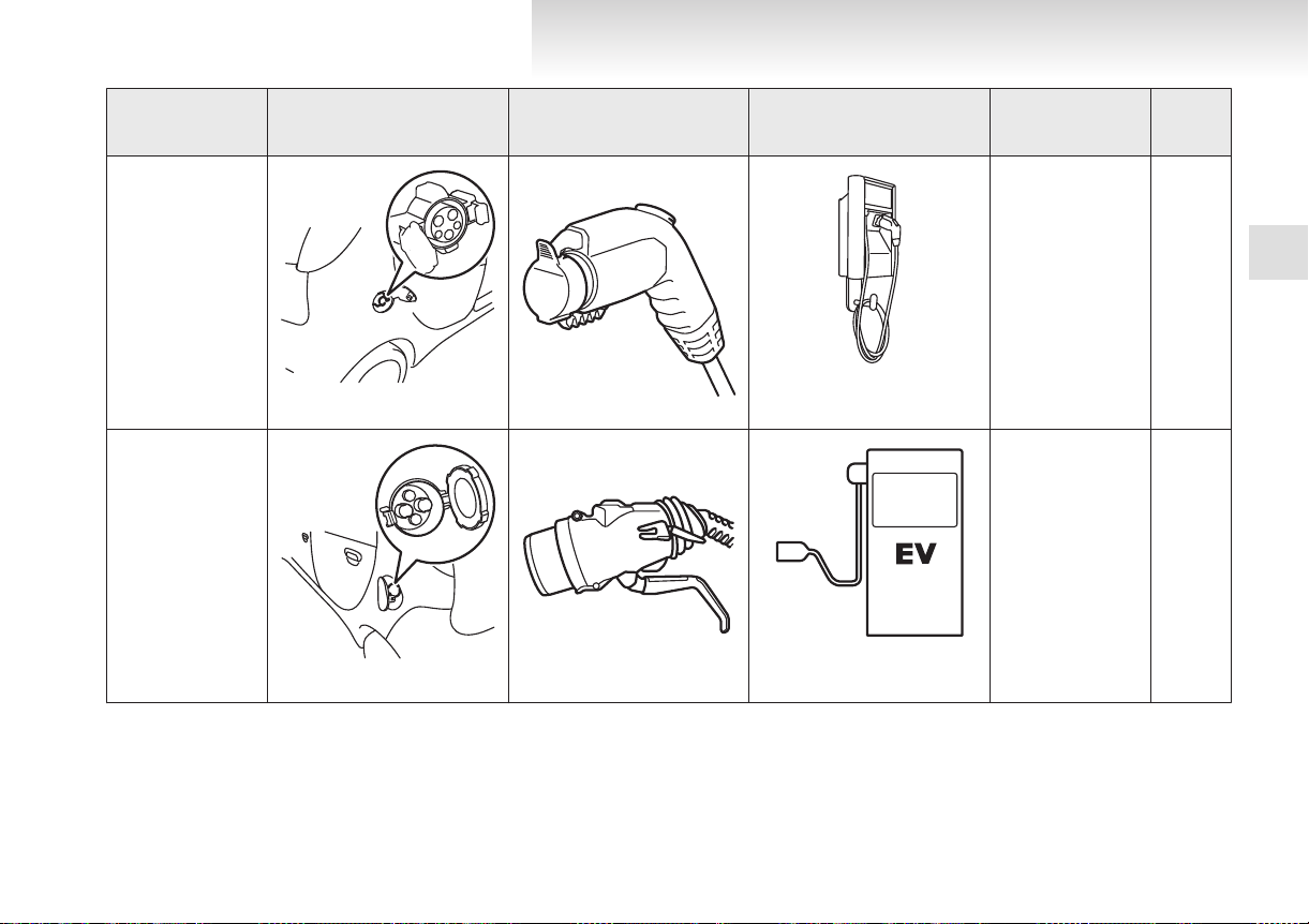
Category Charge port Charge connector Charging Source
Regular charging
(AC 220-240V)
When using a home
or public charging de-
vice (EVSE*1)
Home or public charging de-
Right rear side of vehicle
Quick charging
(charging method
with quick charger)
Left rear side of vehicle
*1
: EVSE = Electric Vehicle Supply Equipment
*2
: Use this time as a guide because the rated AC voltage and the rated current value may differ from country to country.
vice
Public charging stations
where available
Charging time with
fully discharged bat-
tery
230V/16A: About 6
About 30 minutes for
*2
hours
80 % charge
Reference
1
p. 1-08
p. 1-12
1-03
Page 26
Charging
OHAE13E1
Battery
are two types of batteries installed in your ve-
There
hicle: a traction battery for operating the motor (electric motor unit) and air conditioning as well as an
auxiliary battery for starting the electric motor unit
and operating the lamps, wipers, etc. This chapter
explains charging of the traction battery.
1
NOTE
The auxiliary battery is automatically charg-
l
ed while the ready indicator is illuminated or
during charge for the traction battery.
Refer to “Ready indicator” on page 4-09.
If the auxiliary battery is flat, the electric mo-
l
tor unit cannot be started. Also, the charging
cannot be started.
Refer to “Emergency starting” on page 7-02.
E08300100027
Basic knowledge for charging
There
are two types of charging: regular charging
and quick charging.
Regular charging is performed through the onboard charger using rated AC 220-240 V outlet as
the power source.
The rated AC voltage may differ from country to
country.
Quick charging is performed with the quick charger compatible with i-MiEV.
E08300200031
WARNING
reduce the risk of electric shock or
To
l
fire due to electric leak, always use an outlet protected by a residual current detector, rated for amperage equal to or greater than the value specified by
MITSUBISHI MOTORS, and that is connected to a dedicated branch circuit. If
the circuit is shared, and another electrical device is being used at the same time
the vehicle is charging, the breaker may
trip and the circuit may cause adverse interference on MCB (Moulded Circuit
Board) and household electrical appliances such as TVs and audio systems.
It is possible to charge even in rain or
l
snow. However, be sure to pay attention
to the following:
• Never connect or disconnect the
charge connector with a wet hand to
prevent an electric shock.
• Never make the connection wet when
charging.
Never charge in bad weather such as
heavy rain, strong wind and with the risk
WARNING
of lightning. Also, do not keep opening
the
inner lid and the charging lid or do
not leave the EV charging cable in outdoor areas. Doing so could lead to water
entering the charge connector or the
charge port, resulting in fire or an electric shock.
If the connected part of the charging plug
l
has been buried in snow while charging,
turn off the hand switch or the breaker
connected with the outlet first, then remove the snow and disconnect the charging plug. If your vehicle body has been
buried in snow while charging, remove
the snow and then disconnect the charge
connector.
CAUTION
Do
not attempt to perform a jump start
l
on the auxiliary battery at the same time
that the traction battery is being charged.
Doing so may damage the vehicle or charging cable and could cause injury. Refer to
“Emergency starting” on page 7-02.
NOTE
Repeatedly
l
may reduce the battery capacity. In usual
charge, regular charging is recommended.
To maintain the capacity of the traction bat-
l
tery, the following is recommended:
• Fully charge the vehicle in regular charg-
performing only quick charging
ing every two weeks.
1-04
Page 27
• Do not repeat charging near the full
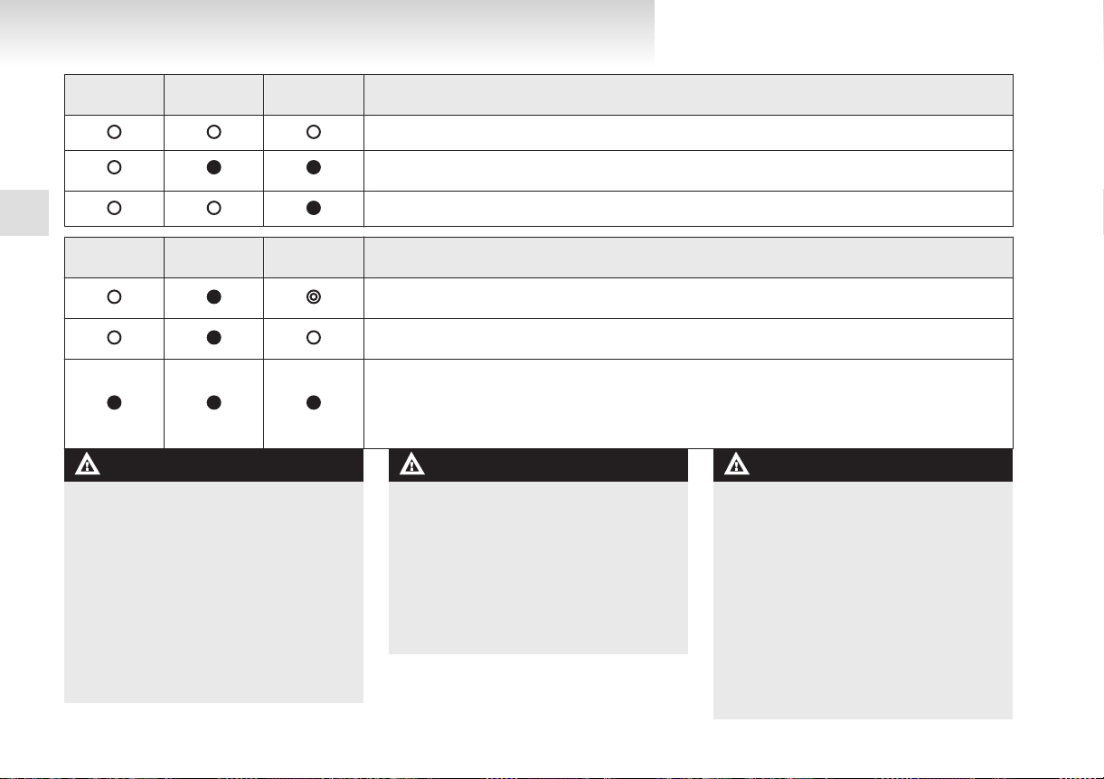
Indicator (LED)
(Green)
(Orange)
(Red)
READY
CHARGE
FAULT
OHAE13E1
charge level.
The quick charging gives priority when the
l
regular charging and the quick charging are
performed at the same time.
At this time, the regular charging will be stopped.
The progress of the battery capacity loss de-
l
pends on the vehicle usage and the environment.
We recommend to do regular charging from
2 segments or less to charge completely at
least once in 3 months.
The procedure lets the battery remaining indicator adjusted automatically.
In the event of an electrical power outage
l
while charging, charging restarts automatically with the restoration of electricity.
Charging
1
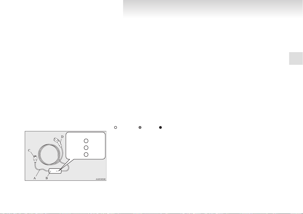
Your vehicle is equipped with the EV charging cable (A) with control box (B).
EV charging cable*
The indicator illuminates/blinks in the following
conditions.
: Illuminates : Blinking : Not illuminates
E08301100066
1-05
Page 28
Charging
OHAE13E1
READY
(Green)
1
READY
(Green)
WARNING
the green or orange indicator does not
If
l
illuminate or the red indicator blinks or illuminates during regular charging,
please contact a MITSUBISHI MOTORS
Authorized Service Point.
Do not charge with the EV charging ca-
l
ble banded or rolled.
The cable may be heated and resulting in
fire.
Do not alter or disassemble the EV charg-
l
ing cable.
Doing so could cause fire, an electric
shock or injury.
CHARGE
(Orange)
CHARGE
(Orange)
FAULT
(Red)
FAULT
(Red)
Normal operating condition of the control box
Every time the charging cable plug (C) is connected to an outlet, all indication lamps illuminate for 0.5 seconds.
After initial processing is completed, when the regular charge connector is not connected to the vehicle, or the
regular charge connector is connected to the vehicle but charging is not being performed.
While the traction battery is being charged
Abnormal operating condition of the control box and corrective action
When an electric leakage occurs or the EV charging cable malfunctions
Stop use immediately and contact a
When the EV charging cable malfunctions
Stop use immediately and contact a
If the control box indication lamp does not illuminate after connecting the charging cable plug to the outlet,
check the circuit breaker for the outlet. If the breaker has tripped, the circuit may not be suitable for use with
EV charging cable. You should have a licensed electrician inspect and repair the electrical circuit. If the breaker is not tripped, stop using the EV charging cable and contact a
Point.
WARNING
sure to install the cap to the regular
Be
l
charge connector and store the EV charging cable at a place where the cable is not
exposed to water or dust. Entry of foreign
matter such as water or dust at the metal
terminal of the regular charge connector
or charging cable plug may cause a fire
or malfunction. Contact with metal such
as wire or tool may cause fire, an electric
shock or malfunction.
MITSUBISHI MOTORS Authorized Service Point.
MITSUBISHI MOTORS Authorized Service Point.
MITSUBISHI MOTORS Authorized Service
WARNING
force the connection if the EV charg-
Never
l
ing cable or connector shows damage or
is not easily connected due to foreign material entering the connector or the outlet. And never use an outlet that is worn,
damaged, or will not hold the plug firmly.
Doing so could cause fire, an electric
shock, or short circuit.
Pay attention to the following for han-
l
dling the EV charging cable.
Damage to the cable could cause fire, an
electric shock, or short circuit.
• Do not pull with undue force.
• Do not twist.
1-06
Page 29
WARNING
Hook
Rope
OHAE13E1
• Do not drag.
•
Do not put an object on top.
• Do not put the cable close to a heating
unit including heater.
• Do not drop the regular charge connector or do not give strong impact to
it.
CAUTION
Do
not charge with the outlet that is small-
l
er than the current value described on
the control box.
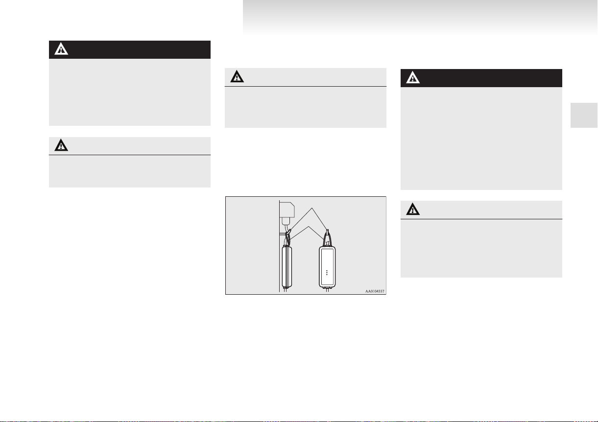
Handling and storing the control box
E08301200025
CAUTION
charging, it must be prevented be-
While
l
ing damaged to the control box by the attached rope as shown in the following illustration.
NOTE
Use
the hook with load capacity over 4 kg,
l
that weight is the EV charging cable.
Check the rope has no damage or no loose be-
l
fore use.
Charging
3. Wipe
all moisture off and dry in a shaded,
well-ventilated area.
WARNING
cleaning, be sure to remove the charg-
In
l
ing cable plug and the regular charge connector from the outlet. Do not connect or
disconnect the plug and the connector
with wet hands. Doing so could cause an
electric shock.
Do not have the metal terminal of the reg-
l
ular charge connector and the charging
cable plug be exposed to water or neutral
detergent. Operation with water could
cause fire or an electric shock.
1
NOTE
All
indicators are illuminated momentarily
l
for confirming operation when the charging
cable plug is inserted into an outlet. After
that the green indicator is continuously illuminated.
The orange indicator will go off when the
l
charging is completed. The green indicator is
continuously illuminated while the charging
plug is inserted into an outlet.
Cleaning the EV charging cable
1. Gently
2. Wipe off all the detergent with a soft cloth
wipe off with gauze or other soft
cloth soaked with a 3 % aqueous solution of
neutral detergent.
dipped in fresh water and thoroughly wrung
out.
E08301300042
CAUTION
Never use benzine, petrol, or other organ-
l
ic solvents, or acid or alkaline solvents. Doing so could cause deformation, discolour, or malfunction. Also, these substances may be present in various cleaners, so
check carefully before use.
1-07
Page 30

Charging
OHAE13E1
Regular charging (charging
method with rated AC 220-240 V
outlet)
WARNING
1
safety, do not allow children or peo-
For
l
ple who are not familiar with charging to
charge for themselves. Also, do not use
the charge connector within reach of children.
Persons who use electro-medical appara-
l
tus such as implantable cardiac pacemaker or implantable cardioverter defibrillator must check effect from charging with
the manufacturer of electro-medical apparatus.
If you use any medical electric devices,
l
take into account the following precautions.
• Do not stay inside the vehicle.
• Do not go inside the vehicle, for example to remove or place an item in the
passenger compartment.
• Do not open the rear hatch, for example to remove or place an item in the
cargo area.
Charging may affect the operation of electric medical devices and result in serious
personal injury or death.
Do not charge with the EV charging ca-
l
ble banded or rolled.
Doing so the cable may be heated and this
might result in fire.
E08300900054
WARNING
Before charging, make sure that there is
l
no foreign matter such as dust at the regular charge port and the regular charge
connector.
At this time, do not touch the regular
charge port.
When the regular charge connector is con-
l
nected to the charge port, prevent foreign
matter such as water or dust from entering in the port.
Connection with foreign matter such as
water or dust may cause fire or an electric shock. Do not perform charging if
there might be strong exposure to water
at the connection.
Never pull the cable to remove the plug.
l
And never submerge the EV charging connector, control box or plug in water.
Please observe the following in order to
l
prevent accidents during charging such
as electrocution.
• Always use a charging cable that suitable for this vehicle.
• Do not charge another vehicle using
the attached EV charging cable.
Doing so the cable may be heated and
this might result in fire.
• Make sure to use an outlet that is protected from water entering.
• Do not perform charging with the
body cover.
• Do not remove and insert the plug and
connector with wet hands.
• Do not charge the battery if there is a
risk of lightning.
WARNING
While it is normal for the connector and
l
charging cable to become warm during
charging, discontinue use immediately if
the connector or charging cable becomes
hot to the touch.
While it is normal for the control box to
l
become warm during charging, discontinue use immediately if the control box becomes hot to the touch.
If abnormal smells are detected or the ve-
l
hicle produces smoke, quickly stop charging.
Do not perform charging at a poorly ven-
l
tilated place with surroundings covered.
Keep sparks, cigarettes, and flames away
from the auxiliary battery.
Flammable gas generated from the auxiliary battery in charging may be filled in a
building, resulting in explosion.
If charging is inevitably required, ventilate the area well.
Grasp the regular charge connector when
l
connecting or disconnecting the EV charging cable.
Grasping the cable could cause an electric shock, short circuit, and/or fire.
During charging, the cooling fans inside
l
the bonnet room may automatically be operated even if the electric motor switch is
in the “LOCK” position.
Keep your hands away from the cooling
fan during charging.
1-08
Page 31

CAUTION
OHAE13E1
Do not perform charging from other pow-
l
er source like a generator. Doing so could
cause a malfunction.
NOTE
If
the charge connector is not easily connec-
l
ted to the charge port due to foreign material
entering, never force the connection. Doing
so could damage the charging equipment or
the vehicle. Contact a MITSUBISHI
MOTORS Authorized Service Point.
The on board charger is only for rated AC
l
220-240 V outlets.
When connecting or disconnecting the regu-
l
lar charge connector, insert/pull out the connector straight.
Also, do not incline or twist the connector.
Doing so could cause a bad connection or malfunction.
Make sure to lock the doors to prevent theft,
l
etc. during charging.
Charging from rated AC 220-240 V outlet
1. Fully
apply the parking brake and place the
selector lever to the “P” (PARK) position.
2. Stop the electric devices such as lamps and
turn the electric motor switch to the “LOCK”
position.
E08301000065
the regular charging lid opener (A) at
3. Pull
the bottom left/right of the instrument panel
to open the regular charging lid (B) at the
right rear side of the vehicle.
4. Press the tab (C) to open the inner lid (D).
WARNING
Do not touch the metal terminal of the reg-
l
ular charge port (E) and the regular
charge connector.
Doing so could cause an electric shock and/
or malfunction.
CAUTION
Do
not leave for a long time with the in-
l
ner lid opened. It becomes impossible to
charge if a foreign material is entered to
the regular charge port.
NOTE
There
l
l
5. Insert the charging cable plug into an outlet.
NOTE
l
l
is a hole on the charge port for water
drainage. If this hole is blocked and water
gets trapped in the charge port, do not
charge. Contact a MITSUBISHI MOTORS
Authorized Service Point.
If the charge port is frozen, melt the ice using a hair drier. Forcing the charge connector
to connect while frozen could result in malfunction.
The shape of the charging cable plug and outlet may differ from country to country as
shown in the illustration.
Use the following outlets.
Charging
1
1-09
Page 32

Switzerland 250 V/10 A
Italy 250 V/10 A
Denmark 250 V/13 A
UK, Ireland 250 V/13 A
Germany, Spain, France, Sweden, etc. 250 V/16 A
Industrial plug for Europe 250 V/16 A
Charging
OHAE13E1
Make sure that the plug is inserted all the
l
way into the outlet before use.
To reduce the risk of electric shock or
l
fire due to electric leak, always use an outlet protected by a residual current detec-
1
tor, rated for amperage equal to or greater than the value specified by
MITSUBISHI MOTORS, and that is connected to a dedicated branch circuit. If
the circuit is shared, and another electrical device is being used at the same time
the vehicle is charging, the breaker may
trip and the circuit may cause adverse interference on MCB (Moulded Circuit
Board) and household electrical appliances such as TVs and audio systems.
To reduce the risk of electric shock, con-
l
nect only to a properly earthed and waterproofed outlet.
WARNING
6. Remove the cap (F) on the regular charge connector (G) and make sure that there is no foreign matter such as dust at the end of the regular charge connector and the regular charge
port.
7. Connect
the regular charge connector until a
click sound is heard without pressing the button (H).
1-10
Page 33

CAUTION
OHAE13E1
Do not clasp the top of regular charge con-
l
nector. It could cause injury to touch the
protrusion on the lid.
Charging
1
NOTE
If
the electric motor switch is turned to the
l
“START” position with the regular charge
connector connected to the regular charge
port, the electric motor unit cannot be started.
8. Make sure that the charging indicator on the
instrument cluster is illuminated.
If the charging indicator is not illuminated,
charging is not started.
sure that the regular charge port, the
Make
plug and the connector are appropriately connected, and perform charging from Step 5
again.
NOTE
When the regular charge connector is connec-
l
ted to the charge port, the charging indicator
is blinking. When charging is started, the
charging indicator is illuminated.
The charge level for traction battery can be
l
checked with the energy level gauge (I) on
the instrument cluster.
Refer to “Energy level gauge” on page 4-06.
9. Charging
cator turns off. Pull out the regular charge connector while pressing the button (J).
is complete when the charging indi-
NOTE
Charging
l
case, also, pull out the regular charge connector while pressing the button.
10. Close the inner lid and close the regular charging lid.
can be stopped half way. In this
1-11
Page 34

Charging
OHAE13E1
NOTE
Make
l
11. Remove the charging cable plug from the out-
1
12. Install the cap on the regular charge connector.
sure that the inner lid is completely
closed.
If the regular charging lid is forcibly closed
without completely closing the inner lid, the
hinge on the inner lid may be broken.
let.
WARNING
After
l
l
charging, be sure to close the inner
lid and the regular charging lid completely.
Be careful that water or dust does not enter in the regular charge port, inner lid
and regular charge connector.
Entry of water or dust could cause electric leakage, resulting in fire or electric
shock.
After charging, be sure to disconnect the
charge connector from the charge port.
If the charge connector is only partially
engaged and the connector latch is unlocked, you could turn the electric motor
switch to the “START” position and the
vehicle could start moving. It could lead
to an unexpected accident.
CAUTION
After charging, be sure to disconnect the
l
plug from the outlet.
If the plug is left connected to the outlet,
immersion in water or tampering may
cause leakage or an electric shock.
Quick charging (charging
method with quick charger)
WARNING
sure to use the quick charger compati-
Be
l
ble with i-MiEV.
Use of a non-compatible quick charger
may cause fire or malfunction.
For the quick charger compatible with
i-MiEV, consult a MITSUBISHI
MOTORS Authorized Service Point.
For operation of quick chargers, follow
l
the manual of each quick charger.
Persons who use electro-medical appara-
l
tus such as implantable cardiac pacemaker or implantable cardioverter defibrillator must check effect from charging with
the manufacturer of electro-medical apparatus. Electro-medical apparatus operations could be affected by charging.
Before charging, make sure that there is
l
no foreign matter such as dust at the
quick charge port and the quick charge
connector.
At this time, do not touch the quick
charge port.
E08301400069
1-12
Page 35

WARNING
OHAE13E1
When the quick charge connector is con-
l
nected to the quick charge port, prevent
foreign matter such as water or dust
from entering in the port.
Connection with foreign matter such as
water or dust may cause fire or an electric shock. Do not perform charging if
there might be strong exposure to water
at the connection.
During charging, the cooling fans inside
l
the bonnet room may automatically be operated even if the electric motor switch is
in the “LOCK” position.
Keep your hands away from the cooling
fan during charging.
NOTE
If
the charge connector is not easily connec-
l
ted to the charge port due to foreign material
entering, never force the connection. Doing
so could damage the charging equipment or
the vehicle. Contact a MITSUBISHI
MOTORS Authorized Service Point.
The quick charger might be installed in the
l
public parking space, some chargers are not
suitable for this vehicle. Check the manual of
each quick charger when charging.
The charge connector and the EV charging ca-
l
ble stick out of the vehicle body while charging, so be careful that your body does not get
stuck with them or they do not touch the next
vehicle.
vehicle equipped with a quick charge
The
l
port is compatible with most CHAdeMO (Japanese industry standard) connectors on charging stations.
Make sure to lock the doors to prevent theft,
l
etc. during charging.
1. Fully apply the parking brake and move the
selector lever to the “P” (PARK) position.
2. Stop the electric devices such as lamps, air
conditioning, etc. and turn the electric motor
switch to the “LOCK” position.
3. Pull the quick charging lid opener (A) at the
bottom left/right of the driver’s seat to open
the quick charging lid (B) at the left rear side
of the vehicle.
4. Press the tab (C) to open the inner lid (D).
Charging
WARNING
not touch the metal terminal of the
Do
l
quick charge port (E) and the quick
charge connector.
Doing so could cause an electric shock and/
or malfunction.
CAUTION
Be sure to insert the quick charge connec-
l
tor straight into the quick charge port
right up to the base.
Failure to do so may result in the traction
battery not charging or could cause damage to the charging equipment.
Do not leave for a long time with the in-
l
ner lid opened. It becomes impossible to
charge if a foreign material is entered to
the quick charge port.
1
1-13
Page 36

1
OHAE13E1
Charging
NOTE
There
l
l
is a hole on the charge port for water
drainage. If this hole is blocked and water
gets trapped in the charge port, do not
charge. Contact a MITSUBISHI MOTORS
Authorized Service Point.
If the charge port is frozen, melt the ice using a hair drier. Forcing the charge connector
to connect while frozen could result in malfunction.
5. Connect the quick charge connector in the
quick charge port to begin charging.
For connecting and disconnecting, follow the
instruction manual for each quick charger.
6. Make sure that the charging indicator on the
instrument cluster is illuminated.
If the charging indicator is not illuminated,
charging is not started.
Follow the manual of each quick charger.
NOTE
When
l
l
the regular charge connector is connected to the charge port, the charging indicator
is blinking. When charging is started, the
charging indicator is illuminated.
The charge level for traction battery can be
checked with the energy level gauge (F) on
the instrument cluster.
Refer to “Energy level gauge” on page 4-06.
Operation
l
hicle body during quick charging.
This noise comes from operation of the
traction battery cooling system, and it is
not a malfunction.
Since the traction battery cooling system
l
uses cool air of the air conditioning, the
air conditioning is automatically operated.
After quick charging, if the area under
the vehicle is wet, transparent and loose,
it is dehumidified water from the air conditioning and not a malfunction.
noise may be heard from the ve-
Disconnect the quick charge connector according to the manual of the quick charger.
CAUTION
the quick charge connector is heavier
As
l
in comparison to the regular charge connector, allowing it to drop could cause
damage to the vehicle or charge connector or personal injury. When removing
the connector, be sure to pull it out
straight and as carefully as possible.
Do not leave the quick charge connector
l
connected to the quick charge port after
charging.
Doing so, someone might stumble and it
could cause an injury or the quick charging connection might be damaged by playing it.
8. Close
the inner lid and close the quick charg-
ing lid.
WARNING
charging, be sure to close the inner
After
l
lid and the quick charging lid completely.
Be careful that water or dust does not enter in the quick charge port, inner lid and
quick charge connector.
Entry of water or dust could cause fire,
electric shock or short circuit.
7. Charging is complete when the charging indicator turns off.
1-14
Page 37

WARNING
OHAE13E1
After charging, be sure to disconnect the
l
charge connector from the charge port.
If the charge connector is only partially
engaged and the connector latch is unlocked, you could turn the electric motor
switch to the “START” position and the
vehicle could start moving. It could lead
to an unexpected accident.
NOTE
If
the electric motor switch is turned to the
l
“START” position with the quick charge connector connected to the quick charge port,
the electric motor unit cannot be started.
Be sure to disconnect the quick charge connector before start.
Charging may be completed before full
l
charge. This is a control for efficient charge
and not a malfunction.
To achieve full charge, repeat charging from
Step 5 again.
Make sure that the inner lid is completely
l
closed.
If the quick charging lid is forcibly closed
without completely closing the inner lid, the
hinge on the inner lid may be broken.
Charging
1
1-15
Page 38

Charging
OHAE13E1
Charging cannot be started.
1
Regular charging cannot
be started.
Charging Timer by
MiEV remote cannot be
started.
Charging troubleshooting guide
Symptom Possible cause Possible solution
The electric motor switch is in the ON
position.
The traction battery is already fully
charged.
The temperature of the traction battery
is too high or too low to charge.
The auxiliary battery is discharged. The traction battery can be charged if the vehicle electrical systems cannot be turned on. If
The vehicle has a malfunction. The vehicle or charger may have a malfunction. Confirm if the warning lamp on the meter is
There is no electrical power coming
from the outlet.
The charge connector is not connected
correctly.
Refer to “Actions to be taken when the MiEV Remote system does not operate correctly” on page 1-32.
Before charging, place the electric motor switch in the “LOCK” position.
Charging cannot be performed if the traction battery is already fully charged. Charging automatically turns off if the traction battery is fully charged.
Confirm the traction battery temperature.
Refer to “Cautions and actions to deal with intense heat” on page
tions to deal with intense cold” on page 08.
the battery is discharged, charge or Emergency start the auxiliary battery. Refer to “Emergency starting” on page 7-02.
illuminated. Confirm if the indicator on the charger is indicating a malfunction. If a warning
is displayed, stop charging and contact a MITSUBISHI MOTORS Authorized Service Point.
Confirm that there has not been a power failure. Make sure the breaker is on. If an outlet with
a timer device installed is used, power will only be available at the time set by the timer.
Confirm if the Ready (green) indicator on the control box is illuminated.
Confirm the charge connector is connected correctly.
E08301500031
06 and “Cautions and ac-
1-16
Page 39

Symptom Possible cause Possible solution
OHAE13E1
Regular charging is discontinued.
Quick charging cannot be
started.
Quick charge is discontinued.
There is no power coming from the outlet.
The EV charging cable has been disconnected.
The button on the regular charge connector has been pressed.
The temperature of the traction battery
is too hot or too cold to charge.
Charging is stopped by the regular
charge timer.
The charge connector is not connected
correctly and/or not locked.
The self-diagnostic function of the
quick charge device returns a negative
result.
The power switch of the quick charger
is off.
Charging is stopped by the quick
charge timer.
Charging stops at 80% capacity. Charging is designed to stop when the traction battery capacity reaches 80%. If you need to
The power supply for the quick charger is off.
There may have been a electrical power failure, or the breaker may have failed.Charging will
resume when the power source is reset.
Check that the EV charging cable has not been disconnected.
If the charge connector button is pressed for a long period of time, charging will be stopped.
Start the charging procedure again.
Confirm the traction battery temperature.
Refer to “Cautions and actions to deal with intense heat” on page 06 and “Cautions and actions to deal with intense cold” on page 08.
Charging will stop depending on the timer function setting of the regular charge device. If
you need to charge the traction battery more, start the charging procedure again.
Check that the charge connector is connected correctly and that it is locked.
There is a possibility that the vehicle has a malfunction. Stop charging and contact a
MITSUBISHI MOTORS Authorized Service Point.
Check the power switch of the quick charger.
Charging will stop depending on the timer function setting of the quick charge device.If you
need to charge the traction battery more, start the charging procedure again.
charge the traction battery more than 80%, start the charging procedure again.
Check whether the power supply for the quick charger is off.
Charging
1
1-17
Page 40

Glass antenna
MiEV
Remote
Charging
OHAE13E1
1
MiEV Remote System*
MiEV Remote System has the following three
The
functions.
Timer Charging
l
When the EV charging cable (regular
charger) is connected, the batteries will
only charge during the pre-set time period selected using the MiEV Remote.
Remote Climate Control
l
When the EV charging cable (regular
charger) is connected, the air-conditioner
can be activated for up to 30 minutes prior to using the vehicle. This feature can
be used to cool or heat the car and to activate the front and rear window defroster.
Traction Battery Level Indicator
l
The charge remaining in the traction battery can be confirmed through the MiEV
Remote.
1-18
E08301800034
WARNING
Individuals who use implantable pace-
l
makers or implantable cardiovascular-defibrillators should keep away from the external and internal transmitters. The electromagnetic waves used in the MiEV Remote System may affect the operation of
implantable pacemakers and implantable
cardiovascular defibrillators.
Individuals using other electro-medical
l
apparatus besides implantable pacemakers and implantable cardiovascular defibrillators should check with the manufacturer of the apparatus to confirm the effect of the electromagnetic waves used by
the MiEV Remote System. The electromagnetic waves may affect the operations
of the electro-medical apparatus.
Never use the MiEV Remote near medi-
l
cal equipment. Electromagnetic waves
could adversely affect the medical equipment.
Keep the MiEV Remote in the place
l
where children will not touch or play
with the remote.
When bringing the MiEV Remote on
l
flights, do not press any switches on the
MiEV Remote while on the plane. If a
switch is pressed on the plane, the MiEV
Remote emits electromagnetic waves
which like cell phones and other wireless
devices, could interfere with systems on
the airplane.
When carrying the MiEV Remote in a
bag, be careful that no switches on the
MiEV Remote can be pressed by mistake.
CAUTION
Never disassemble or modify the MiEV
l
Remote. No user serviceable parts are inside except batteries.
Disassembling or modifying the MiEV Re-
l
mote or removing a label from the MiEV
Remote may violate regulations.
NOTE
The
MiEV Remote system uses radio waves.
l
The MiEV Remote can operate within approximately 100 m from the vehicle.
In the following environments or situations,
the MiEV Remote may not transmit and receive radio waves correctly. As a result, the
remote may not operate properly.
• When the vehicle and the MiEV Remote
are separated by a concrete wall.
• When there is a metal wall between the
vehicle and the MiEV Remote.
• When the vehicle is surrounded by other
tall vehicles.
• When the vehicle and/or the MiEV Remote is near a facility emitting strong radio waves, such as a television tower, a
transformer substation, a broadcasting station or an airport.
• When other electrical equipment such as
computers or cell-phones are placed near
the MiEV Remote.
• When the MiEV Remote touches something metallic, or is covered by a metal object.
• When batteries for the MiEV Remote are
weak.
Page 41

and buzzer from the MiEV Remote
OHAE13E1
Melody
l
can be turned on or off.
Refer to “To turn on/off melody and buzzer”
on page 1-30.
The transmitter signal will reach further
l
when the antenna of the MiEV Remote is
fully extended and held upright.
The onboard antenna is printed on the right
l
side delta glass of the vehicle.
When the MiEV Remote is not used for
l
more than 30 seconds, the MiEV Remote
will automatically turn off.
Some charge facilities have a timer function
l
which turns the power supply on and off automatically. When using a charge facility
with this timer function, please adjust the
charging time set by the MiEV Remote to be
consistent with the timer used by of the charging facility.
When you need additional MiEV Remotes,
l
please contact your MITSUBISHI MOTORS
Authorized Service Point. Up to four MiEV
Remotes can be used per vehicle.
MiEV Remote
Switches
1- Power/communication
hold to turn remote on. Press quickly to transmit command to vehicle.
2- MODE switch - The display of the MiEV Re-
mote is changed in order of “ON timer”,
“OFF timer” and “Remote Climate Control”
by pressing this switch.
3- Manual charge switch (this can also cancel
the timers and Remote Climate Control)
4- Ring
5- UP switch - scrolls up the display items
6- DOWN switch - scrolls down the display
items
7- Display
8- Antenna
switch - Press and
E08301900022
Charging
Display (LCD monitor)
1- Blinks
2- The indicator lights up during charging. The
3- Blinks if there is an operation or communica-
4- Shows remaining charge of the Traction Bat-
5-
6- Indicates
when communicating with vehicle,
and when error occurs.
indicator blinks when the manual charging
button is pressed. The indicator will rapidly
blink, if EV charging cable (regular charger)
is not connected when the Charging Timer or
Remote Climate Control is set.
tion error.
tery. Blinks if battery has less than 20%
charge.
: Indicates ON timer is set
: Indicates OFF timer is set
amount of time until Charging Tim-
er is complete.
1
1-19
Page 42

1
OHAE13E1
Charging
7- When Remote Climate Control is set, display
mode set to operate:
COOL: Pre-Cooling Mode
HEAT: Pre-Heating Mode
: Pre-Defroster Mode
A/C OFF: Remote Climate Control OFF
CAUTION
Never leave the MiEV Remote in a place
l
where it will be subject to high temperatures, such as in direct sunlight, or subject to extreme low temperatures.
The MiEV Remote can be damaged and
may not properly operate.
CAUTION
Never drop or hit the MiEV Remote. Do
l
not apply force to bend the antenna.
These can cause damage to or failure of
the remote.
If the MiEV Remote gets wet, please wipe
l
water off immediately. Water entering
the MiEV Remote can cause a failure.
Basic operation of the MiEV Remote
1-20
Page 43

Press the power/communication switch for 1 second or more to turn the MiEV Remote on.
Press the MODE switch to
show the ON timer display.
Press the MODE switch to
show the OFF timer display.
Press the MODE switch to
show the Remote Climate
Control display.
Traction Battery
Level Indicator
Repeat these steps
to set other MODE.
Press the UP switch or DOWN switch to select desired setting.
Press the power/communication switch to send the data to the vehicle.
Press the power/communication switch for 3 seconds or more to turn the MiEV Remote off or the MiEV Remote will
automatically turn off 30 minutes after it has been sent the data to the vehicle.
ON timer OFF timer Remote Climate Control Traction Battery
Level Indicator
OHAE13E1
Charging
1
1-21
Page 44

Charging
OHAE13E1
Charging Timer
The Charging Timer can be set as follows.
To set the timer, the following conditions must be
1
met.
timer: Time from the present to when
ON
l
charging will begin.
OFF timer: Time from the start of charging
l
to the end of charging
Selector lever: “P” (PARK) position
l
Electric motor switch: “LOCK”position
l
EV charging cable (regular charger): Connec-
l
ted
WARNING
Improper
l
erty damage, and serious injury or death.
Before Charging Timer, carefully read
and follow the instructions in “Basic
knowledge for charging” on page 1-04
and “Regular charging (charging method
with rated AC 220-240 V outlet)” on page
1-08.
NOTE
Charging
l
charging system.
charging can result in fire, prop-
Timer cannot be used with a quick
E08302000033
1-22
Page 45

ON Timer = 2h
1. Setting of ON Timer = 2h, OFF Timer = 8h
2. When Charging timers are set up, initially 4h for ON-Timer
and 8h for OFF-Timer are displayed.
OFF Timer = 8h
OFF-Timer initial
display = 8h
ON-Timer initial
display = 4h
Charging
Waiting
Charging
OHAE13E1
Example of Charging Timer
1. In case you set the timer at 9:00 PM so that charging starts at 11:00 PM
and stops at 7:00 AM of the following day (for 8 hours).
2. In case you set the timer at 7:00 PM so that charging starts and stops at the
E08302100034
same time the last time.
1
1-23
Page 46

Charging
OHAE13E1
To turn the MiEV Remote ON/OFF
1. Extend the antenna (A) and press the power/
communication switch (B) for 1 second or
more to turn the MiEV Remote on. When it
properly communicates with the vehicle, the
vehicle information will be displayed on the
screen.
1
2. To
turn the MiEV Remote off, press the power/communication switch (B) for 3 seconds
or more and store the antenna (A).
To set the ON timer
the regular charging. Refer to “Regular
1. Start
charging (charging method with rated AC
220-240 V outlet)” on page 1-08.
2. Turn on the MiEV Remote. Refer to “To
turn the MiEV Remote ON/OFF” on page
1-24.
3. Press the UP switch (C) or the DOWN
switch (D) once. The time remaining from
the present to the time that was previously
set for the ON timer will be displayed and
blink.
E08302200019
E08302300036
NOTE
The
remaining time for the last charging is
l
displayed with blinking as follows.
Example: If you set the charging starting
time to 11:00 PM of the day before:
Present time Remaining time Display
9:00 PM 2:00 2h
9:10 PM 1:50 2h
9:40 PM 1:20 1.5h
the MiEV Remote cannot communicate
If
l
with the vehicle, the remaining time will not
be displayed.
4. If you need to change the remaining time for
the ON timer, press the UP switch (C) or the
DOWN switch (D) to change the remaining
time.
The remaining time can be changed within
range from 0 to 19.5 hours in half hour in-
the
crements.
NOTE
When
l
l
5. Press the power/communication switch (B)
you want to start charging at the same
time as last time, changing the remaining
time is unnecessary.
When the remaining time is set to 0h, the
charging starts immediately after step 5.
for less than 1 second to send the setting data
to the vehicle.
The MiEV Remote will sound melodies on
transmission and reception.
NOTE
The melodies can be turned off. Refer to “To
l
turn on/off melody and buzzer” on page
1-30.
1-24
Page 47

l
Energy level gauge
Charging indicator
OHAE13E1
l
l
6. To turn off the MiEV Remote, refer to “To
NOTE
l
If a communication error occurs or the MiEV
System is not functioning properly,
Remote
the buzzer will sound. Refer to “Display of
MiEV Remote during communicating with
vehicle” on page 1-27.
If the OFF Timer is unset when setting the
ON timer, the OFF timer will be automatically set with “fully charged”.
To set OFF Timer, refer to “To set OFF Timer” on page 1-26.
turn the MiEV Remote ON/OFF” on page
1-24.
The energy level gauge in the instrument panel on the vehicle will illuminate and the charging indicator will blink approximately 30 seconds after the vehicle has received the setting
for the ON timer.
After approximately 30 seconds, the energy
level gauge and the charging indicator will
go off, and the vehicle will be prepared for
the timer charging.
Turning
l
“ON” position or the “ACC” position will cancel the timer charging.
If the MODE switch is pressed while chang-
l
ing the ON timer setting, the change will be
cancelled.
The
l
be illuminated while the vehicle is charging.
If
l
fore the time set by the ON timer, the timer
charging is not cancelled. If the charge connector is re-connected again before starting
the charge or setting the charge timers, the
timer charging will resume.
the electric motor switch to the
symbol on the MiEV Remote will
the charge connector is disconnected be-
Charging
To start the charging immediately after the ON timer has been set
on the MiEV Remote. Refer to “To
1. Turn
turn the MiEV Remote ON/OFF” on page
1-24.
2. Press the UP switch (C) or the DOWN
switch (D) once, and the remaining time
from the present to the time set for the ON
timer will be displayed and blink.
3. Change
4. Press the power/communication switch (B)
5. Turn off the MiEV Remote. Refer to “To
the remaining time to 0h by pressing
the UP switch (C) or the DOWN switch (D).
for less than 1 second to send the setting data
to the vehicle. The MiEV Remote will sound
melodies on transmission and reception. The
charging will start.
Refer to “Regular charging (charging method
with rated AC 220-240 V outlet)” on page
1-08.
turn the MiEV Remote ON/OFF” on page
1-24.
E08302400011
1
1-25
Page 48

Charging
OHAE13E1
To set OFF Timer
The OFF timer can be set during the regular charging or after setting the ON timer.
1. When the power of MiEV Remote is off,
turn the power on. Refer to “To turn the
MiEV Remote ON/OFF” on page 1-24.
2. Press the MODE switch (E) to change the dis-
1
play to the OFF timer (2).
1- Shown the ON timer
Shown the OFF timer
23- Shown the Remote Climate Control
3. Press the UP switch (C) or the DOWN
switch (D) once.
E08302500038
The time set last time for the OFF timer will
be displayed and blink.
4. If
you need to change the time for the OFF
timer, press the UP switch (C) or the DOWN
switch (D) to change the time.
• The time can be changed within the
range from 0.5h to 19.5h by half hour
and can be changed to “-h”.
• When “-h” is displayed, the charging
will end when the traction battery is
fully charged.
NOTE
To display “-h”, press the UP switch (C)
l
when 19.5h is displayed or press the DOWN
switch (D) when 0.5h is displayed.
NOTE
The
melodies can be turned off. Refer to “To
l
turn on/off melody and buzzer” on page
1-30.
If a communication error occurs or the MiEV
l
Remote System is not functioning properly,
the buzzer will sound. Refer to “Display of
MiEV Remote during communicating with
vehicle” on page 1-27.
If the ON timer is unset when setting the
l
OFF timer, the ON timer will be automatically set with “0h”.
6. Turn off the MiEV Remote. Refer to “To
turn the MiEV Remote ON/OFF” on page
1-24.
NOTE
The energy level gauge in the instrument pan-
l
el will illuminate and the charging indicator
will blink approximately 30 seconds after the
vehicle has received the setting for the OFF
timer.
After approximately 30 seconds, the energy
level gauge and the charging indicator will
then go off, and the vehicle will be prepared
5. Press the power/communication switch (B)
for less than 1 second to send the setting data
to the vehicle.
The MiEV Remote will sound melodies on
transmission and reception.
1-26
Page 49

Energy level gauge
Charging indicator
l
OHAE13E1
l
l
l
for Charging Timer in accordance with the
ON/OFF setting.
The symbol on the MiEV Remote illuminates
while the traction battery is charging.
The Charging Timer will be cancelled if the
electric motor switch is turned to the “ON”
or “ACC” position.
Once the traction battery is fully charged, the
charging will end even if this is before the
time set by the OFF timer.
If the charge connector is disconnected during charging, the OFF charging timer will be
cancelled.
Display of MiEV Remote during communicating with vehicle
communicates with the vehicle when the power
It
of the MiEV Remote is turned on with pressing the
power supply/communication switch (B) for 1 second or more and if the power supply/communication switch (B) is pressed for less than 1 second
while the power of the MiEV Remote is on.
If the normal reception melody sounds after the
transmitting melody, it is set completion.
Communication symbol (F) blinks while communicating with the vehicle.
If the buzzer sounds and the ERROR symbol (G)
blinks, a problem is detected. Refer to “Actions to
be taken when the MiEV Remote system does not
operate correctly” on page 1-32.
To cancel Charging Timer
There are two methods to cancel Charging Timer.
By using the MiEV Remote
l
By
operating the electric motor switch on the
l
vehicle
E08302600039
E08302700030
NOTE
If
the Charging Timer is cancelled during
l
charging, the charging will continue until the
traction battery is fully charged.
If the Charging Timer is cancelled before
l
charging starts, charging will start immediately and continue until the traction battery is
fully charged.
Charging Timer cannot be cancelled by dis-
l
connecting the charge connector before the
time set by the ON timer. The Charging Timer will resume when the charging connector
is again connected to the vehicle.
A- By using the MiEV Remote
1. When the power of MiEV Remote is off,
turn the power ON. Refer to “To turn the
MiEV Remote ON/OFF” on page 1-24.
2. Press the manual charging switch (H),
then press the power/communication
switch (B) for less than 1 second.
Charging
1
1-27
Page 50

1
OHAE13E1
Charging
NOTE
If
the manual charging switch (H) is pressed,
l
B- By operating the electric motor switch on the
symbol of MiEV Remote will blink.
the
The Remote Climate Control is also stopped.
3. Cancelling Charging Timer is complete,
and the MiEV Remote will sound two different melodies.
4. Turn off the MiEV Remote. Refer to “To
turn the MiEV Remote ON/OFF” on
page 1-24.
vehicle
Turn the electric motor switch to the “ACC”
or “ON” position, then turn back to the
“LOCK” position
Cancelling the Charging Timer is now complete.
Remote Climate Control
WARNING
Remote Climate Control, even when
The
l
set, cannot be relied upon to maintain
safe vehicle cabin temperatures while the
vehicle is stopped or parked. Never leave
children or persons requiring supervision/
nursing unattended inside the vehicle.
The temperature inside the vehicle could
become extremely high or low resulting
in a risk of heat stroke or hyperthermia
that could result in death.
In addition, children can activate
switches and controls, resulting in injury
or a fatal accident.
While the Remote Climate Control is acti-
l
vated, keep away from the cooling fan under the bonnet, since the cooling fan may
automatically operate even if the electric
motor switch is in the “LOCK” position.
NOTE
The
Remote Climate Control works regard-
l
less of the position of the air conditioning
switch or dial on the vehicle. While the Remote Climate Control is activated, the air conditioning switch or dial on the vehicle will
not affect operation of the cooler, heater or
defroster.
The Remote Climate Control will automati-
l
cally stop 30 minutes after the Remote Climate Control has been set.
E08302800015
Remote Climate Control is operated by
The
l
electric power supplied through the EV charging cable (regular charger).
Under the following conditions, the effect of
l
the Remote Climate Control can be decreased.
• When the outside temperature is very high.
• When the sunlight is strong.
• When the outside temperature is very low.
When the Remote Climate Control is activa-
l
ted while charging the traction battery, the
time required to fully charge the traction battery will become longer or the amount of
charge may decrease if the OFF timer has
been set.
While the Remote Climate Control is activa-
l
ted, if a heated seat switch is ON, the heated
seat will operate.
To operate the Remote Climate Control
The following conditions must be met to operate
the Remote Climate Control.
Selector lever: P (PARK) position.
l
Electric motor switch: LOCK position.
l
charging cable (regular charger): Connec-
EV
l
ted.
Quick charging: Not used.
l
Traction Battery Level Indicator: Shows one
l
bar or more.
Refer to “Traction Battery Level Indicator”
on page 1-30.
All doors and the liftgate: Closed.
l
E08302900016
1-28
Page 51

Charging
OHAE13E1
WARNING
Improper charging can result in fire, prop-
l
erty damage, and serious injury or death.
Carefully read and follow instructions in
“Basic knowledge for charging” on page
1-04 and “Charging method with rated
AC 220-240 V outlet” on page 1-09.
1. Start
charging. Refer to “Charging method
with rated AC 220-240 V outlet” on page
1-09.
2. Turn on the MiEV Remote. Refer to “To
turn the MiEV Remote ON/OFF” on page
1-24.
3. Press the MODE switch (E) to change the
mode to Remote Climate Control (3).
1- Shown the ON timer
2-
Shown the OFF timer
3- Shown the Remote Climate Control
4. Select a desired mode by pressing UP switch
(C) or DOWN switch (D).
The modes will be changed in the order from
1 to 4 by pushing the UP switch.
1- COOL: Pre-Cooling Mode
2-
HEAT: Pre-Heating Mode
3-
: Pre-Defroster Mode
4-
A/C OFF: Remote Climate Control OFF
5. Press the power/communication switch (B)
for less than 1 second to send the setting to
the vehicle. The MiEV Remote will sound
melodies on transmission and reception.
NOTE
The
melodies can be turned off. Refer to “To
l
turn on/off melody and buzzer” on page
1-30.
If a communication error occurs or the MiEV
l
Remote System is not functioning properly,
the buzzer will sound. Refer to “Display of
MiEV Remote during communicating with
vehicle” on page 1-27.
6. Turn off the MiEV Remote. Refer to “To
turn the MiEV Remote ON/OFF” on page
1-24.
To stop the Remote Climate Control
The Remote Climate Control can be stopped by either of the following methods.
using the MiEV Remote, after pressing
A- By
the manual charging switch (H), press the
power/communication switch (B) for less
than 1 second.
E08303000030
1
1-29
Page 52

Charging
OHAE13E1
B- By using the MiEV Remote, select the A/C
OFF mode and send the setting. Refer to “To
operate the Remote Climate Control” on
page 1-28.
C- Turn the electric motor switch to the “ACC”
or the “ON” position.
D- Disconnect the regular charge connector
from the vehicle.
1
NOTE
The Remote Climate Control will not stop if
l
the doors or liftgate are opened after the Remote Climate Control has started.
To turn on/off melody and buzzer
1. Turn
on the MiEV Remote. Refer to “To
turn the MiEV Remote ON/OFF” on page
1-24.
To turn off the sounds, press the UP
l
switch (C) while pressing MODE switch
(E).
To turn on the sounds, press the DOWN
l
switch (D) while pressing MODE switch
(E).
E08303100015
2. Turn off the MiEV Remote. Refer to “To
turn the MiEV Remote ON/OFF” on page
1-24.
Traction Battery Level Indicator
The remaining energy in the traction battery can be
checked using the MiEV Remote.
1. If
the MiEV Remote has been turned off,
turn on the MiEV Remote. Refer to “To turn
the MiEV Remote ON/OFF” on page 1-24.
2. Current remaining energy in the traction battery is shown on the display while the MiEV
Remote is ON.
The remaining energy is shown by the number of segments displayed.
3 segments: Full or nearly full
:
2 segments: Moderate
:
1 segment: Low
:
0 segments: Empty or nearly empty
:
E08303200016
NOTE
More
l
than
traction battery is necessary to operate the Remote Climate Control.
3. Turn off the MiEV Remote. Refer to “To
turn the MiEV Remote ON/OFF” on page
1-24.
remaining quantity in the
Replacement of batteries for the MiEV Remote
E08303300017
CAUTION
Remote is a precision electronic de-
MiEV
l
vice with a built-in signal transmitter. Do
not disassemble or touch internal parts.
Keep away from water or dust.
Be careful not to break the tab on the bat-
l
tery cover when removing or installing
the battery cover.
About the battery
Two coin type batteries are used. Replace if necessary to assure proper operation.
NOTE
Standard
l
about 1 year. Battery life can vary depending
on environmental and usage conditions.
battery life on the MiEV Remote is
E08303400018
1-30
Page 53

To replace the batteries
Coin type batteries
CR2032
OHAE13E1
1. Before replacing the batteries, remove static
electricity from your body by touching a metal grounded object.
2. The battery cover (B) lifts when the slide portion (A) is moved to the direction indicated
by the arrow.
E08303500019
Charging
4. Remove the old batteries.
5. Install two new batteries (D) with the “+”
side up.
1
3. By
moving the battery cover (B) in the direction indicated by the arrow, the tabs (C) on
the battery cover will come out and the battery cover can be removed.
6. Attach
7. Confirm the MiEV Remote can be turned
the battery cover (A) in the reverse or-
der from the way you have detached it.
ON. Refer to “To turn the MiEV Remote ON/
OFF” on page 1-24.
NOTE
Replace both batteries with new ones at the
l
same time.
If you prefer, you can have the batteries re-
l
placed by a MITSUBISHI MOTORS Authorized Service Point.
1-31
Page 54

Charging
OHAE13E1
Actions to be taken when the MiEV Remote system does not operate correctly
the following actions when the system does not operate correctly. If the system still does not operate correctly after the action(s) have been taken, a system
Take
component may not be working properly. Please consult a MITSUBISHI MOTORS Authorized Service Point to check it.
Phenomena Cause Remedy
Charging does not start when the regular charge connector is inserted. “ON” timer has been set. Cancel the “ON” timer.
1
MiEV Remote does not operate normally.
The following symbol blinks when the
power supply/communication switch
on the MiEV Remote is pressed.
ERROR symbol
l
l
symbol
The regular charge connector is not
locked completely.
A household electrical outlet, which
the
EV charging cable is connected to,
is shut down.(e.g. disconnected plug)
MiEV Remote is not powered on. Batteries in the MiEV Remote are deNo indication lamps come on when the
remote is turned on.
Melody or buzzer does not sound. Melody or buzzer has been disabled. Enable the melody or buzzer.
Blinks after about 1 second.
fective or the batteries are discharged.
Electrical
l
in the vicinity of the MiEV Remote.(e.g. personal computer)
Electrical noise source is present
l
between the vehicle and the
MiEV Remote.
noise source is present
Lock the regular charge connector securely.
Turn on the household electrical outlet
and make sure the plug is securely connected.
Replace the batteries in the MiEV Remote.
Refer to “Replacement of batteries for
the MiEV Remote” on page 1-30.
Refer to “To turn on/off melody and
buzzer” on page 1-30.
Move away from the noise source.
E08303600036
1-32
Page 55

Phenomena Cause Remedy
OHAE13E1
Blinks after about 10 seconds. The MiEV Remote antenna is not ex-
The symbol below blinks about 10 seconds after the power/communication
switch on the MiEV Remote is pressed.
ERROR symbol
l
tended.
Out of effective communication range.
(e.g. too far away from the vehicle, or
radio signal is interfered)
The electric motor switch is at the position other than “LOCK” position.
Electrical
l
in the vicinity of the vehicle.
Electrical noise source is present
l
between the vehicle and the
MiEV Remote.
Auxiliary battery is discharged. Charge or replace the auxiliary battery.
Some errors occur while the system is
processing.
noise source is present
Charging
Extend the MiEV Remote antenna to
communicate.
Move to the location where the system
reaches the effective communication
range.
Turn the electric motor switch to the
“LOCK” position.
Move away from the noise source.
Refer
to “Emergency starting” on page
7-02, “Low voltage electrical system”
on page 9-05.
Press the power/communication switch
again.
1
1-33
Page 56

Charging
OHAE13E1
Phenomena Cause Remedy
Timer charging is not possible. After the power/communication switch
is pressed, the following symbol blinks
for several seconds.
ERROR symbol
l
l
symbol
1
After the power/communication switch
is pressed, the following symbol blinks
for several seconds.
ERROR symbol
l
Regular charge connector is not inserted or not locked completely.
A household electrical outlet, to which
the EV charging cable (regular charger) is connected, is shut down.(e.g. disconnected plug)
An earth leakage circuit breaker at the
household electrical outlet is working.
Otherwise, the power supply at the
household electrical outlet is cut off.
If the charging unit is equipped with
the timer function, the power supply to
the unit has been cut off.
The selector lever is in a position other
than P (PARK).
Quick charging is in progress. (The
symbol illuminates.)
The temperature of the traction battery
has exceeded about 60 °C.
The temperature of the traction battery
has been under about -25 °C.
Lock the regular charge connector securely.
Turn on the household electrical outlet
to which the EV charging cable (regular charger) is connected.
Check the earth leakage circuit breaker
and the power supply cut.
Preset the Charging Timer while the
charging unit with timer function is
powered on.
Set the selector lever to the “P”
(PARK) position.
Terminate the quick charging, or wait
until the quick charging completes.
Allow the temperature of the traction
to reach normal operating tem-
battery
perature. Refer to “Cautions and actions to deal with intense heat” on page
06.
Allow the temperature of the traction
battery to reach normal operating temperature. Refer to “Cautions and actions to deal with intense cold” on page
08.
1-34
Page 57

Phenomena Cause Remedy
OHAE13E1
Timer charging is not possible. Charging is preset, but the specified
charging level is not satisfied.
The charging level is not expec-
l
ted amount.
Is not charged.
l
Is not charged at the preset time.
l
Although the charging is preset, too
much time is needed to charge the system fully.
It is not fully charged. If the charging unit is equipped with
The timer is cancelled or the preset
time is changed by using another
MiEV Remote.
The electric motor switch has been operated before the system is charged.
The temperature of the traction battery
has exceeded about 60 °C.
The temperature of the traction battery
has been under about -25 °C.
Charging timer is not preset correctly. Preset the timed charging again.
The Remote Climate Control has been
activated.
Temperature of the traction battery is
low.
the timer function, the power supply to
the unit has been cut off.
Check whether another person has operated his or her MiEV Remote.
Check whether the electric motor
switch has been operated before the system is charged.
Allow the temperature of the traction
battery to reach normal operating temperature. Refer to “Cautions and actions to deal with intense heat” on page
06.
Allow the temperature of the traction
battery to reach normal operating temperature. Refer to “Cautions and actions to deal with intense cold” on page
08.
Check whether the Remote Climate
Control has been activated.
Refer to “Cautions and actions to deal
with intense cold” on page 08.
Preset the Charging Timer while the
charging unit with timer function is
powered on.
Charging
1
1-35
Page 58

Charging
OHAE13E1
The Remote Climate Control cannot be
activated.
1
Phenomena Cause Remedy
After the power/communication switch
is pressed, the following symbol blinks
for several seconds.
ERROR symbol
l
l
After the power/communication switch
is pressed, the following symbol blinks
for several seconds.
l
l
symbol
ERROR symbol
symbol
The regular charge connector is not inserted or it is not locked completely.
A household electrical outlet, to which
the EV charging cable (regular charge)
is connected, is shut down.(e.g. disconnected plug)
An earth leakage circuit breaker at the
household electrical outlet is working.
Otherwise, the power supply at the
household electrical outlet is cut off.
If the charging unit is equipped with
the timer function, the power supply to
the unit has been cut off.
The traction battery charging level is
low.
Lock the regular charge connector securely.
Turn on the household electrical outlet
to which the EV charging cable (regular charger) is connected.
Check the earth leakage circuit breaker
and the power supply cut.
Preset the Charging Timer while the
charging unit with timer function is
powered on.
Charge the traction battery until the
MiEV Remote illuminates the battery
charging level by at least 1 segment.
1-36
Page 59

Phenomena Cause Remedy
OHAE13E1
The Remote Climate Control cannot be
activated.
The Remote Climate Control cannot be
activated.
After the power/communication switch
is pressed, the following symbol blinks
for several seconds.
ERROR symbol
l
The Remote Climate Control is not activated.
The heated seat is not powered on. The heated seat switch is turned off. Turn on the heated seat switch.
The heated seat becomes hot while the
air conditioning (cooling) is activated.
Any of the doors or liftgate is open. Close all the doors and liftgate.
The selector lever is at the position oth-
er than P (PARK).
Quick charging is in progress.
(The symbol will illuminate.)
The temperature of the traction battery
has exceeded about 60 °C.
The temperature of the traction battery
has been under about -25 °C.
The electric motor switch has been operated before the system is charged.
The temperature of the traction battery
has exceeded about 60 °C.
The temperature of the traction battery
has been under about -25 °C.
The heated seat switch is turned on. Turn off the heated seat switch.
Set the selector lever to the “P”
(PARK) position.
Terminate the quick charging, or wait
until the quick charging completes.
Allow the temperature of the traction
to reach normal operating tem-
battery
perature. Refer to “Cautions and actions to deal with intense heat” on page
06.
Allow the temperature of the traction
battery to reach normal operating temperature. Refer to “Cautions and actions to deal with intense cold” on page
08.
Check whether the electric motor
switch has been operated before the system is charged.
Allow the temperature of the traction
battery to reach normal operating temperature. Refer to “Cautions and actions to deal with intense heat” on page
06.
Allow the temperature of the traction
battery to reach normal operating temperature. Refer to “Cautions and actions to deal with intense cold” on page
08.
Charging
1
1-37
Page 60

Charging
OHAE13E1
Cleaning the MiEV Remote
1. Gently wipe with gauze or another soft cloth
soaked with a 3 % aqueous solution of neutral detergent.
2. Wipe off all the detergent with a soft cloth
dipped in fresh water and thoroughly wrung
out.
1
3. Wipe all moisture off and dry in a shaded,
well-ventilated area.
CAUTION
Never use benzine, petrol, or other organ-
l
solvents, or acid or alkaline solvents. Do-
ic
ing so could cause deformation, discolour, or malfunction. Also, these substances may be present in various cleaners, so
check carefully before use.
E08303700011
1-38
Page 61

Locking and unlocking
OHAE13E1
Keys..............................................................................................2-02
Electronic immobilizer (Anti-theft starting system).....................2-02
Keyless entry system....................................................................2-03
Doors............................................................................................2-05
Central door locks.........................................................................2-06
“Child-protection” rear doors.......................................................2-07
Tailgate.........................................................................................2-08
Electric window control
................................................................2-09
2
Page 62

Locking and unlocking
OHAE13E1
Keys
Two keys are provided. The key fits all locks.
Keep one in a safe place as a spare key.
2
WARNING
When taking a key on flights, do not
l
press any switches on the key while on
the plane. If a switch is pressed on the
plane, the key emits electromagnetic
waves, which could adversely affect the
plane’s flight operation.
When carrying a key in a bag, be careful
that no switches on the key can be easily
pressed by mistake.
E00300102399
key is a precision electronic device with
The
l
a built-in signal transmitter. Please observe
the following in order to prevent malfunctioning.
• Do not leave the key anywhere where exposed to direct sunlight, for example on
the dashboard.
• Do not disassemble or modify.
• Do not excessively bend the key or subject it to strong impacts.
• Do not expose to water.
• Keep away from magnetic key rings.
• Keep away from audio systems, personal
computers, TVs, and other equipment
that generates a magnetic field.
• Keep away from devices that emit strong
electromagnetic waves, such as cellular
phones, wireless devices and high frequency equipment (including medical devices).
• Do not clean with ultrasonic cleaners or
similar equipment.
• Do not leave the key where it may be exposed to high temperature or high humidity.
The electric motor unit is designed so that it
l
will not start if the ID code registered in the
immobilizer computer and the key’s ID code
do not match. Refer to the “Electronic immobilizer” section for details and key usage.
Electronic immobilizer (Anti-
theft starting system)
electronic immobilizer is designed to signifi-
The
cantly reduce the possibility of vehicle theft. The
purpose of the system is to immobilize the vehicle
if an invalid start is attempted. A valid start attempt
can only be achieved by using a key “registered” to
the immobilizer system.
NOTE
In the following cases, the vehicle may not
l
be able to receive the registered ID code
from the registered key and the electric motor unit may not start.
• When the key contacts a key ring or other
metallic or magnetic object (Type A)
• When the key grip contacts metal of another key (Type B)
E00300201928
NOTE
The
key number is stamped on the tag as in-
l
dicated in the illustration.
Make a record of the key number and store
the key and key number tag in separate places, so that you can order a key in the event
the original keys are lost.
2-02
Page 63

• When the key contacts or is close to other
OHAE13E1
immobilizing keys (including keys of other vehicles) (Type C)
In cases like these, remove the object or
additional key from the vehicle key and
turn the key back to the “ACC” or
“LOCK” position. Then try again to start
the electric motor unit. If the electric motor unit does not start, we recommend
you to contact your MITSUBISHI
MOTORS Authorized Service Point.
Two keys are provided.
l
you lose one of them, order a key from
If
your MITSUBISHI MOTORS Authorized
Service Point as soon as possible.
To obtain a replacement or extra spare key,
take your vehicle and any remaining key to
your MITSUBISHI MOTORS Authorized
Service Point. All the keys have to be registered in the immobilizer computer unit. The
immobilizer can register up to 8 different keys.
CAUTION
make any alterations or additions
Don’t
l
to the immobilizer system; alterations or
additions could cause failure of the immobilizer.
Locking and unlocking
Keyless entry system
Press the remote control switch, and all doors and
the tailgate will be locked or unlocked as desired.
1- LOCK switch
UNLOCK switch
23- Indication lamp
E00300302434
To lock
Press the LOCK switch (1), and all doors and the
tailgate will be locked. When they are locked with
the room lamp at the middle (•) position or at the
“DOOR” position, the room lamp and the turn-signal lamps blink once.
To unlock
Press the UNLOCK switch (2), and all doors and
the tailgate will be unlocked. When unlocked with
the room lamp at the (•) position or at the “DOOR”
position, the room lamp will be turned on for approximately 15 seconds and the turn-signal lamps
will blink twice.
2
2-03
Page 64

Locking and unlocking
OHAE13E1
NOTE
The
l
a switch is pressed.
If the UNLOCK switch (2) is pressed and
l
any of the doors or the tailgate is not opened
within approximately 30 seconds, relocking
will automatically occur.
It is possible to modify functions as follows:
l
For further information, please contact your
MITSUBISHI MOTORS Authorized Service
Point.
2
• The time for automatic relocking can be
• The confirmation function (flashing of
• The confirmation function (this indicates
• The number of times the turn-signal
The keyless entry system does not operate in
l
the following conditions:
• The key is left in the key cylinder.
• The door or the tailgate is open.
The remote control switch will operate with-
l
in approximately 4 m from the vehicle. However, the operating range of the remote control switch may change if the vehicle is located near a power station, or radio/TV broadcasting station.
If either of the following problems occurs,
l
the battery may be exhausted.
indication lamp (3) comes on each time
changed.
the turn-signal lamps) can be set to operate only when the doors and the tailgate
are locked or only when the doors and
the tailgate are unlocked.
locking or unlocking of the doors and the
tailgate with the flash of the turn-signal
lamps) can be deactivated.
lamps are flashed by the confirmation
function can be changed.
remote control switch is operated at
• The
the correct distance from the vehicle, but
the doors and the tailgate are not locked/
unlocked in response.
• The indication lamp (3) is dim or does
not come on.
For further information, please contact
your MITSUBISHI MOTORS Authorized Service Point.
If you replace the battery yourself, refer
to “Procedure for replacing the remote
control switch battery” on page 2-04.
If your remote control switch is lost or dam-
l
aged, please contact your MITSUBISHI
MOTORS Authorized Service Point for a replacement remote control switch.
If you wish to add a remote control switch,
l
we recommend you to contact a
MITSUBISHI MOTORS Authorized Service
Point.
A maximum of 4 remote control switches are
available for your vehicle.
Operation of the outside rear-view mirrors
To fold
Within
30 seconds of locking the doors and the tailgate using the LOCK switch (1), press the LOCK
switch twice rapidly to fold the outside rear-view
mirrors.
To extend
Within 30 seconds of unlocking the doors and the
tailgate using the UNLOCK switch (2), press the
UNLOCK switch twice rapidly to return the outside rear-view mirrors to their extended positions.
E00310800119
Procedure for replacing the remote control switch battery
1. Before
2. Remove the screw (A) from the remote con-
3. With
replacing the battery, remove static
electricity from your body by touching a metal part such as doorknob of the room.
trol switch.
the MITSUBISHI mark facing you, insert the clothcovered tip of a straight blade
(or minus) screwdriver into the notch in the
remote control switch case and use it to open
the case.
E00309500204
2-04
Page 65

NOTE
Coin type battery
CR1616
- side
+ side
OHAE13E1
Be
sure to perform the procedure with the
l
MITSUBISHI mark facing you. If the
MITSUBISHI mark is not facing you when
you open the remote control switch case, the
switches may come out.
4. Remove the remote control transmitter from
the remote control switch case. Then, open
the remote control transmitter using the method described in step 3.
6. Install a new battery with the + side (B) down.
Locking and unlocking
Doors
CAUTION
sure the doors are closed: driving
Make
l
with doors not completely closed is dangerous.
Never leave children in the vehicle unat-
l
tended.
Be careful not to lock the doors while the
l
key is inside the vehicle.
E00300402187
2
5. Remove the old battery.
7. Close the remote control transmitter firmly.
8. Place the remote control transmitter in the remote control switch case, then securely close
the remote control switch case.
9. Attach the screw (A) removed in step 2.
10. Check the keyless entry system to see that it
works.
NOTE
You may purchase a replacement battery at
l
an electric appliance store.
A MITSUBISHI MOTORS Authorized Serv-
l
ice Point can replace the battery for you if
you prefer.
CAUTION
When
l
the remote control switch case is
opened, be careful to keep water, dust,
etc. out. Also, do not touch the internal
components.
NOTE
To
prevent the key from being locked inside
l
the vehicle, neither the lock knob on the driver’s door nor the key can be used to lock the
driver’s door when it is open.
To lock or unlock with the key
1- Lock
Unlock
2-
2-05
Page 66

Locking and unlocking
OHAE13E1
To lock or unlock from inside the vehicle
2
1- Lock
Unlock
2-
Pull the inside door handle towards you to open the
door.
NOTE
The driver’s door can be opened without us-
l
ing the lock knob by pulling on the inside
door handle.
Also, all other doors and the tailgate are unlocked at the same time.
To lock without using the key
Set the inside lock knob (1) to the locked position,
and close the door (2).
NOTE
The
driver’s door cannot be locked using the
l
inside lock knob while the driver’s door is
opened.
Central door locks
E00300801852
NOTE
Each
of the doors can be locked or unlocked
l
independently by using the inside lock knob.
Repeated continuous operation between lock
l
and unlock could activate the central door
locking systems built-in protection circuit
and prevent the system from operating. If
this occurs, wait about 1 minute before operating the inside lock knob or the key.
Driver’s door with key
Using the key on the driver’s door locks or unlocks
all doors and the tailgate.
1- Lock
2-
Unlock
2-06
Page 67

Locking and unlocking
OHAE13E1
Driver’s door with inside lock knob
the inside lock knob on the driver’s door
Using
locks or unlocks all doors and the tailgate.
1- Lock
Unlock
2-
Unlocking doors using selector lever
It is possible to unlock all doors and the tailgate using the selector lever by placing it in the “P” position while the electric motor switch is in the “ON”
position.
NOTE
The
vehicle is shipped from the factory with
l
a setting established such that the doors and
the tailgate are not unlocked when the selector lever is placed in the “P” position with
the electric motor switch in the “ON” position. If you wish to change the setting such
that the doors and the tailgate are unlocked,
contact your MITSUBISHI MOTORS Authorized Service Point.
“Child-protection” rear doors
1- Lock
Unlock
2-
Child protection helps prevent the rear doors from
being opened accidentally from the inside.
If the lever is set to the locked position, the rear
door cannot be opened using the inside handle, but
only with the outside handle.
If the lever is set to the “Unlock” position, the
child protection mechanism does not function.
E00300901026
CAUTION
driving with a child in the rear
When
l
seat, please use the child protection to prevent accidental door opening which may
cause an accident.
2
2-07
Page 68

Locking and unlocking
OHAE13E1
When
l
make sure that there are no people nearby and be careful not to hit your head or
pinch your hands, neck, etc.
To open
2
After
unlocking the tailgate, push the switch (A)
and pull up the tailgate.
NOTE
If
l
after pulling the handle, the tailgate cannot
be lifted. If this happens, pull the handle
again and lift the tailgate.
The tailgate cannot be opened when the bat-
l
tery is flat or disconnected.
Tailgate
E00301401161
WARNING
opening and closing the tailgate,
you do not open the tailgate immediately
To close
the tailgate grip (A) downward as illustrated.
Pull
Gently push the upper gate from the outside with
enough force so that it is completely closed. Always ensure the tailgate is securely closed.
CAUTION
When
l
NOTE
l
closing the tailgate, always ensure
your or other person’s fingers cannot be
caught by the tailgate.
Gas
struts (B) are installed to support the tailgate.
To prevent damage or faulty operation.
• Do not hold the gas struts when closing
the tailgate.
• Also, do not push or pull the gas struts.
• Do not attach any plastic material, tape,
etc., to the gas struts.
• Do not tie string, etc., around the gas struts.
• Do not hang any object on the gas struts.
2-08
Page 69

Electric window control
Driver’s switch (LHD)
Driver’s switch (RHD)
OHAE13E1
The electric windows can only be operated with the
electric motor switch in the “ON” position.
E00302200550
WARNING
operating the electric window con-
Before
l
trol, make sure that nothing can get trapped (head, hand, finger, etc.).
Never leave the vehicle without removing
l
the key.
Never leave a child (or other person who
l
might not be capable of safe operation of
the electric window control) in the vehicle
alone.
The child may tamper with the switch at
l
the risk of its hands or head being trapped in the window.
Electric window control switch
Each window opens or closes while the corresponding switch is operated.
E00302301705
1- Driver’s door window
2-
Front passenger’s door window
3- Rear left door window
4- Rear right door window
5- Lock switch
Driver’s switches
The driver’s switches can be used to operate all
door windows.
A window can be opened or closed by operating
the corresponding switch.
Press the switch down to open the window, and
pull up the switch to close it.
If the switch for the driver’s door window is fully
pressed down, the door window automatically
opens completely.
If you want to stop the door window movement,
pull up the switch.
Locking and unlocking
Press the switch down for opening the door window, and pull up the switch for closing.
NOTE
Repeated
l
unit stopped will run down the battery. Operate the window switches only while the electric motor unit is running.
Lock switch
When this switch is operated, the passenger’s
switches
dows and the driver’s switch cannot open or close
any windows other than the driver’s window.
operation with the electric motor
E00303101188
cannot be used to open or close the win-
2
Passenger’s switches
The passenger’s switches can be used to operate
the corresponding passenger’s door windows.
2-09
Page 70

Locking and unlocking
OHAE13E1
To unlock, press it once again.
2
1- Lock
2-
Unlock
WARNING
child may tamper with the switch at
A
l
the risk of its hands or head being trapped in the window. When driving with a
child in the vehicle, please press the window lock switch to disable the passenger’s switches.
Timer function
The door windows can be opened or closed for 30
seconds
after the electric motor switch is turned
from the “ON” position to the “ACC” or “LOCK”
position.
However, once the driver’s door or the front passenger’s door is opened, the windows cannot be operated.
2-10
E00302400927
Page 71

Seat and seat belts
OHAE13E1
Seat...............................................................................................3-02
Seat adjustment.............................................................................3-03
Front seat......................................................................................3-03
Rear seat*.....................................................................................3-05
Head restraints..............................................................................3-07
Seat belts.......................................................................................3-08
Pregnant women restraint.............................................................3-10
Seat belt pretensioner system and force limiter system................3-11
Child restraint...............................................................................3-11
Seat belt inspection.......................................................................3-20
Supplemental restraint system (SRS) - airbag..............................3-20
3
Page 72

Seat and seat belts
OHAE13E1
3
1-Front seat
2-Rear seat*
To adjust forward or backward ® p. 3-03
l
To recline the seatback
l
To adjust seat height (driver’s seat only) ® p. 3-04
l
Heated seats ® p. 3-04
l
To recline the seatback
l
Folding the seatbacks forward ® p. 3-06
l
® p. 3-04
® p. 3-05
Seat
E00400102013
3-02
Page 73

Seat and seat belts
OHAE13E1
Seat adjustment
the driver’s seat so that you are comfortable
Adjust
and that you can reach the pedals, steering wheel,
switches etc. while retaining a clear field of vision.
E00400300633
WARNING
not attempt to adjust the seat while
Do
l
driving. This can cause loss of vehicle control and result in an accident. After adjustments are made, ensure the seating is
locked in position by attempting to move
the seat forward and rearward without using the adjusting mechanism.
Do not allow people or children to ride in
l
any area of your vehicle that is not equipped with seats and seat belts, and make
sure that everyone travelling in your vehicle is in a seat and wearing a seat belt, or
in the case of a child is strapped in a child
restraint.
To minimize the risk of personal injury
l
in the event of a collision or sudden braking, the seatbacks should always be in the
almost upright position while the vehicle
is in motion. The protection provided by
the seat belts may be reduced significantly when the seatback is reclined. There is
greater risk that the passenger will slide
under the seat belt, resulting in serious injury, when the seatback is reclined.
CAUTION
Make sure the seat is adjusted by an
l
adult or with adult supervision for correct and safe operation.
Do not place a cushion or the like be-
l
tween your back and the seatback while
driving. The effectiveness of the head restraints will be reduced in the event of an
accident.
When sliding the seats, be careful not to
l
catch your hand or foot.
Front seat
To adjust forward or backward
Pull the seat adjusting lever and adjust the seat forward
or backward to the desired position, and re-
lease the adjusting lever.
E00400400197
E00400500794
WARNING
To
ensure the seat is locked securely, try
l
to move the seat forward or backward
without using the adjusting lever.
3
3-03
Page 74

Seat and seat belts
OHAE13E1
To recline the seatback
order to recline the seatback, lean forward slight-
In
ly, pull the seatback lock lever up, and then lean
backward to the desired position and release the lever. The seatback will lock in that position.
3
CAUTION
The
reclining mechanism of the seatback
l
is spring loaded, causing it to return to
the vertical position when the lock lever
is operated. When using the lever, sit
close to the seatback or hold it with your
hand to control its return motion.
E00400601008
To adjust seat height (driver’s seat only)
To
adjust the seat height, operate the lever repeated-
ly.
1- Raise
Lower
2-
E00400701054
Heated seats
The
heated seat can be operated with the electric
motor switch in the “ON” position. Operate the
switch as indicated by arrows. The heated seat
switch (A) is for the driver’s seat and the switch
(B) is for the passenger’s seat. The indication lamp
(C) will illuminate while the heater is on.
1- Heater on.
Heater off.
2-
E00401101097
CAUTION
Switch off seat heaters when not in use.
l
Continuous
l
is not illuminated can cause the auxiliary
battery to run down.
If the following types of persons use the
l
heated seats, they might become too hot
use while the ready indicator
3-04
Page 75

Seat and seat belts
OHAE13E1
CAUTION
or receive minor burns (red skin, heat blisters, etc.):
•
Children, elderly or ill people
• People with sensitive skin
• Excessively tired people
• People under the influence of alcohol
or sleep inducing medication, etc.
Do not place heavy objects on the seat or
l
stick pins, needles, or other pointed objects into it.
Do not use a blanket, cushion, or other ma-
l
terial with high heat insulation properties
on the seat while using the heater; this
might cause the heater element to overheat
Do not use benzine, kerosene, petrol, alco-
l
hol or other organic solvents when cleaning the seat. Doing so could damage not
only the seat cover, but also the heater element.
If water or any other liquid is spilled on
l
the seat, allow it to dry thoroughly before
attempting to use the heater.
Turn the heater off immediately if it ap-
l
pears to be malfunctioning during use.
Rear seat*
WARNING
a person sits in the rear seat, pull
When
l
up the head restraint to a height at which
it locks in position. Be sure to make this
adjustment before starting to drive. Serious injuries could otherwise be suffered
as the result of an impact. Refer to “Head
restraints” on page 3-07.
CAUTION
restraint lower anchorages (A) are
Child
l
provided between the seat cushion and
the seatback.
Be careful that the lower anchorages may
be hot due to heat of the electric motor
unit room.
E00401300425
To recline the seatback
In order to recline the seatback, lean forward slightly,
pull the lever, and then lean backward to the desired position and release the lever. The seatback
will lock in that position.
E00401500254
NOTE
It
is possible to adjust the seatback angle in-
l
dependently on each side.
3
3-05
Page 76

Seat and seat belts
OHAE13E1
Folding the seatbacks forward
objects can be loaded into the vehicle if a
Larger
seatback is folded forward.
E00401600330
To replace
the seatback until it locks securely into
1. Raise
place.
2. Push lightly on the seatback to confirm that
it has actually been secured.
2. Pushing the seat cushion as far back as possible,
press the hooks (A) on the underside of
the seat cushion into the right and left stopper installation holes (B) until a click is heard.
CAUTION
not stack luggage in the vehicle higher
Do
l
than the seatback height. Also, firmly secure the luggage.
Serious accidents could result due to unrestrained objects entering the passenger
compartment during sudden braking.
To fold
3
Pull the lever, and fold the rear seatbacks forward.
NOTE
Do
not operate the lever in the wrong direc-
l
tion.
Doing so could damage the lever and make it
impossible to operate the seatback.
Rear seat cushion
The rear seat cushion can be removed. It is removed
when the tyre repair kit stored under the
seat cushion is taken out. Use this function when
putting the seat covers on, etc.
To remove
1. Pull the seat stoppers (A) to unlock the seat
cushion (B).
2. Lift up the seat cushion and pull it towards
you to remove it.
To install
1. Place
the seat belt’s buckles on top of the
seat cushion.
E00401900173
installing the seat cushion, shake it light-
3. After
ly to check that it is properly fixed in position.
3-06
Page 77

Head restraints
OHAE13E1
WARNING
Driving
l
place can cause you and your passengers
serious injury or death in an accident. To
reduce the risk of injury in an accident, always make sure the head restraints are installed and properly positioned when the
seat is occupied.
Never place a cushion or similar device
l
on the seatback. This can adversely affect
head restraint performance by increasing
the distance between your head and the
restraint.
without the head restraints in
E00403301497
To raise the head restraint, move it upward. To low-
the restraint, move it downward while pushing
er
the height adjusting knob (A) in the direction of the
arrow. After adjustment, push the head restraint
downward and make sure that it is locked.
Seat and seat belts
Installation
that they are facing the correct direction,
Confirm
and then insert them into the seatback while pressing the height adjusting knob (A) in the direction indicated by the arrow.
CAUTION
Confirm
l
(A) is correctly adjusted as shown in the
illustration, and also lift the head restraints to ensure that they do not come
out of the seatback.
that the height adjusting knob
3
To adjust height
Adjust
the head restraint height so that the centre
of the head restraint is as close as possible to eye
level to reduce the chances of injury in the event of
collision. Any person too tall for the head restraint
to reach their seated eye level, should adjust the restraint as high as possible.
To remove
Lift
the head restraint with the height adjusting
knob (A) pushed in.
CAUTION
head restraints for the seats differ in
The
l
shape and size. When installing head restraints, make sure the head restraints
are fitted in their respective seats and do
not install the head restraints in the
wrong direction.
3-07
Page 78

Seat and seat belts
OHAE13E1
Seat belts
protect you and your passengers in the event of
To
an accident, it is most important that the seat belts
be worn correctly while driving.
The front seat belts have a pretensioner system.
These belts are used the same way as a conventional seat belt.
Refer to “Seat belt pretensioner system and force
limiter system” on page 3-11
E00404800636
WARNING
place the shoulder belt over your
Always
l
3
shoulder and across your chest. Never
put it behind you or under your arm.
One seat belt should be used by only one
l
person. Doing otherwise can be dangerous.
The seat belt will provide its wearer with
l
maximum protection if the recliner seatback is placed in fully upright position.
When the seatback is reclined, there is
greater risk that the passenger will slide
under the belt, especially in a forward impact accident, and may be injured by the
belt or by striking the instrument panel
or seatbacks.
Seat belts should always be worn by ev-
l
ery adult who drives or rides in this vehicle, and by all children who are tall
enough to wear seat belts properly.
Other children should always use proper
child restraint systems.
Remove any twists when using the belt.
l
WARNING
No modifications or additions should be
l
made by the user which will either prevent the seat belt adjusting devices from
operating to remove slack, or prevent the
seat belt assembly from being adjusted to
remove slack.
Never hold a child in your arms or on
l
your lap when riding in this vehicle, even
if you are wearing your seat belt. To do
so risks severe or fatal injury to the child
in a collision or sudden stop.
Always adjust the belt to a snug fit.
l
Always wear the lap portion of the belt
l
over your hips.
3-point type seat belt (with emergency locking mechanism)*
This type of belt requires no length adjustment.
worn, the belt adjusts itself to the movement
Once
of the wearer, but in the event of a sudden or strong
shock, the belt automatically locks to hold the wearer’s body.
E00404901504
3-08
Page 79

Seat and seat belts
OHAE13E1
NOTE
You
can check if the belt locks by pulling it
l
forward quickly.
To fasten
1. Pull the seat belt out slowly while holding
the latch plate.
NOTE
When the seat belts cannot be pulled out in a
l
locked condition, pull the belts once forcefully and then return them. After that, pull the
belts out slowly once again.
2. Insert the latch plate into the buckle until a
“click” is heard.
WARNING
wear the lap portion of the belt
Never
l
across your abdomen. During accidents it
can press sharply against the abdomen
and increase the risk of injury.
WARNING
The seat belts must not be twisted when
l
worn.
3. Pull
the belt slightly to adjust slackness as de-
sired.
To unfasten
Hold the latch plate and push the button on the buckle.
NOTE
As
the belt retracts automatically, keep hold-
l
ing the latch plate while retracting so that the
belt stows slowly. Failure to do this could
damage the vehicle.
Seat belt warning
Driver’s and front passenger’s seat belt reminder/ warning lamp
The driver’s and front passenger’s seat belt warning lamp is located on the instrument panel.
When the electric motor switch is turned to the
“ON”
position, if a driver or a front passenger has
not fastened the seat belt, the warning lamp will illuminate.
Having passed approximately 1 minute since the
electric motor switch is turned to the “ON” position, if the seat belt remains unfastened when the vehicle is driven, the warning lamp will flash and the
tone will sound intermittently for approximately 90
seconds.
If the seat belt subsequently remains unfastened,
the warning lamp and tone will issue further warnings each time the vehicle starts moving from a
stop. And if the passenger unfastens the seat belt
while driving, the warning will operate in the same
way.
When the seat belt is fastened, the warnings will stop.
E00413000025
E00414800020
3
3-09
Page 80

Seat and seat belts
OHAE13E1
NOTE
For
the front passenger seat, the warning func-
l
tion works only while a person is sitting on
the seat.
When luggage is placed on the front passen-
l
ger seat, a sensor in the seat cushion may, depending on the weight and position of the luggage, cause the warning tone to sound and
the warning lamp to come on.
Rear passenger’s seat belt warning lamps*
The rear passenger’s seat belt warning lamps are located on the instrument panel.
3
If the electric motor switch is turned to the “ON”
position
while a seat belt is not fastened, the warning lamp comes on for approximately 30 seconds
to remind the rear passenger to fasten the seat belt.
If the vehicle is driven with the seat belt still unfastened, the warning lamp comes on for approximately another 30 seconds. (This illumination happens
only the first time the vehicle starts moving with
the seat belt still unfastened.)
The warning lamp goes off when the seat belt is fastened.
E00414900021
NOTE
The
warning lamps come on even if no one
l
is sitting on the rear seat.
If a seat belt is unfastened while the vehicle
l
is being driven, the tone sounds for approximately 1 second and the warning lamp
comes on for approximately 30 seconds.
If the seat belts are initially fastened but a
l
seat belt is unfastened while the vehicle is stationary and the vehicle is then driven with
the seat belt still unfastened, the warning
lamp comes on again for approximately 30
seconds.
Pregnant women restraint
WARNING
belts work for everyone, including
Seat
l
pregnant women. Pregnant women
should use the available seat belts. This
will reduce the likelihood of injury to
both the woman and the unborn child.
The lap belt should be worn across the
thighs and as snug against the hips as possible, but not across the waist. Consult
your doctor if you have any additional
questions or concerns.
E00405600077
3-10
Page 81

Seat and seat belts
OHAE13E1
Seat belt pretensioner system and
force limiter system
driver’s seat and front passenger’s seat each
The
have a seat belt equipped with a pretensioner system.
Pretensioner system
The pretensioner system will retract its respective
seat
belts instantaneously, thus maximizing the seat
belt’s effectiveness, if there is a frontal impact severe enough to injure the driver and/or front passenger and the electric motor switch is in the “ON” or
“START” position.
E00405700166
E00405801164
WARNING
obtain the best results from your pre-
To
l
tensioner seat belt, make sure you have adjusted your seat correctly and wear your
seat belt properly.
CAUTION
Installation
l
pairs in the vicinity of the pretensioner
seat belts or floor console must be performed in line with MITSUBISHI
MOTORS guidelines. It is important to
do so because the work could affect the
pretensioner systems.
of audio equipment or re-
CAUTION
If you need to scrap the vehicle, please con-
l
sult a MITSUBISHI MOTORS Authorized Service Point. It is important to do
so because unexpected activation of the
pretensioner seat belts could cause injuries.
NOTE
The
pretensioner seat belts will be activated
l
if the vehicle suffers a severe frontal impact,
even if the seat belts are not worn.
The pretensioner seat belts are designed to
l
work only once. After the pretensioner seat
belts have been activated, we recommend
you have them replaced by a MITSUBISHI
MOTORS Authorized Service Point.
SRS warning lamp
This warning lamp is shared by the SRS airbags
and
the pretensioner seat belts. Refer to “SRS warn-
ing lamp” on page 3-29.
Force limiter system
In the event of a collision, each force limiter system
will effectively absorb the load applied to the
seat belt to minimize the impact to the passenger.
E00405900315
E00406000209
Child restraint
When
transporting children in your vehicle, some
type of child restraint system should always be
used according to the size of the child. This is required by law in most countries.
The regulations concerning driving with children in
the front seat may differ from country to country.
You are advised to comply with the relevant regulations.
E00406401747
WARNING
possible, put children in the rear
When
l
seat. Accident statistics indicate that children of all sizes and ages are safer when
properly restrained in the rear seat rather than in the front seat.
Holding a child in your arms is no substi-
l
tute for a restraint system. Failure to use
a proper restraint system can result in severe or fatal injury to the child.
Each child restraint device or fixing is to
l
be used only by one child.
3
3-11
Page 82

Front passenger’s airbag ON
Seat and seat belts
OHAE13E1
Caution for installing the child restraint on vehicles with a front passenger airbag
label shown here is attached on vehicles with a
The
front passenger airbag.
3
WARNING
Extreme Hazard!
l
Do not use a rearward facing child restraint on a seat protected by an airbag in
front of it!
E00406500318
Use rearward facing child restraints in the rear seat
or turn off the front passenger’s airbag ON-OFF
switch. (Refer to “To turn an airbag off” on page
3-23)
WARNING
REARWARD FACING CHILD RE-
A
l
STRAINT must NOT be used in the front
passenger seat if the front passenger’s airbag has not been deactivated. The force
of an inflating airbag could kill or cause
serious injuries to the child. A rearward
facing child restraint must only be used
in the rear seat.
A FORWARD FACING CHILD RE-
l
STRAINT should be used in the rear seat
whenever possible; if used in the front
seat, turn off the front passenger’s airbag
ON-OFF switch.
Infants and small children
When
transporting infants and small children in
your vehicle, follow the instruction given below.
Instruction:
For
small infants, an infant carrier should be
l
used. For small children whose height when
seated allows the shoulder belt to lie in contact with the face or the throat, a child seat
should be used.
The child restraint system should be appropri-
l
ate for the child’s weight and height and properly fit in the vehicle. For a higher degree of
safety: THE CHILD RESTRAINT SYSTEM
SHOULD BE INSTALLED IN THE REAR
SEAT.
E00406600999
3-12
Page 83

NOTE
OHAE13E1
Before
l
purchasing a child restraint system,
try installing it in the rear seat to make sure
there is a good fit. Because of the location of
the seat belt buckles and the shape of the seat
cushion, it may be difficult to securely install
some manufacturer’s child restraint systems.
If the child restraint system can be pulled forward or to either side easily on the seat cushion after the seat belt has been tightened,
choose another manufacturer’s child restraint
system.
WARNING
installing a child restraint system,
When
l
refer to the instructions provided by the
manufacturer of the restraint system. Failure to do so can result in severe or fatal
injury to the child.
After installation, push and pull the child
l
restraint system back and forth, and side
to side, to see that it is properly secured.
If the child restraint system is not installed securely, it may cause injury to the
child or other occupants in case of an accident or sudden stops.
When the child restraint system is not in
l
use, keep your child restraint system secured with the seat belt or remove it from
the vehicle in order to prevent it from being thrown around inside the vehicle during an accident.
the lower anchorage in the rear seat
• To
ONLY if the child restraint has ISOFIX
mountings (See page 3-18).
• To the seat belt (See page 3-19).
Older children
Children who have outgrown the child restraint system should be seated in the rear seat and wear combination lap shoulder belt.
The lap portion of the belt should be snug and positioned
low on the abdomen so that it is below the
top of the hip-bone. Otherwise, the belt could intrude into the child’s abdomen during an accident
and cause injury.
E00406700277
Seat and seat belts
3
Depending on the seating position in the vehicle
and the child restraint system that you
have, the child restraint can be attached using one of the following two locations:
3-13
Page 84

Seat and seat belts
OHAE13E1
Suitability for various ISOFIX positions
Mass group Size class Fixture
Carrycot F ISO/L1 X
G ISO/L2 X
0 - Up to 10 kg
0+ - Up to 13 kg
3
I - 9 to 18 kg
II & III - 15 to 36 kg
#1
: When installing a child restraint system, adjust the front seat in position more than 2 notches forward from the centre of its fore-aft adjustment range.
(0-9 months)
(0-2 years)
(9 months-4 years)
(4-12 years)
E ISO/R1 X
E ISO/R1
D ISO/R2 X
C ISO/R3 X
D ISO/R2 X
C ISO/R3 X
B ISO/F2 IUF
B1 ISO/F2X
A ISO/F3 IUF
Vehicle ISOFIX positions
Rear (Left side/Right side)
IL*1, IL*2,
IUF, IL*
X
CAUTION
When installing a child restraint system, prevent the head restraint from touching the child restraint system by removing it or adjusting its height.
l
When installing a child restraint system, prevent the front seats from touching the child restraint system.
l
If the driver’s seat touches the child restraint system, install the child restraint system in the rear seat of the passenger’s side.
E00411400490
#1
3
3-14
Page 85

Definition of characters to be inserted in the table above:
OHAE13E1
IUF- Suitable for ISOFIX forward child restraints systems of universal category approved for use in the mass group.
l
IL- Suitable for particular ISOFIX child restraint systems given in the following list (MITSUBISHI MOTORS genuine parts).
l
X- ISOFIX position not suitable for ISOFIX child restraint systems in this mass group.
l
IL (Genuine part information)
Genuine part No. ECE No.
1
*
2
*
3
*
#2
: To be available in the middle of 2012
MZ314393 (Child restraint system),
MZ314394 (ISOFIX base)
MZ314509 (Child restraint system)#2,
MZ314394 (ISOFIX base)
MZ313045 E1-04301133
NOTE
MITSUBISHI MOTORS
l
For further information, please contact a MITSUBISHI MOTORS Authorized Service Point.
Europe B.V. reserves the right to changes without any prior announcement.
Seat and seat belts
E1-04301146
E1-04301146
3
3-15
Page 86

Seat and seat belts
OHAE13E1
Suitability for various seating positions
Mass group
Activated airbag
0 - Up to 10 kg
0+ - Up to 13 kg
I -9 to 18 kg
3
II & III -15 to 36 kg
#3
: With front passenger’s airbag deactivated by means of front passenger’s airbag ON-OFF switch
(0-9 months)
(0-2 years)
(9 months-4 years)
(4-12 years)
Front passenger
X X X
X
X
X
CAUTION
When installing a child restraint system, prevent the head restraint from touching the child restraint system by removing it or adjusting its height.
l
When installing a child restraint system, prevent the front seats from touching the child restraint system.
l
If the driver’s seat touches the child restraint system, install the child restraint system in the rear seat of the passenger’s side.
Definition of characters to be inserted in the table above:
U- Suitable for “universal” category restraints approved for use in this mass group.
l
L- Suitable for particular child restraints in the following list (
l
X- Seat position not suitable for children in this mass group.
l
MITSUBISHI MOTORS genuine parts).
Deactivated air-
#3
bag
2
L*1, L*
4
L*3, L*
5
L*
Seating position
Rear (Left side/Right side)
U, L*
2
4
5
U, L*1, L*
U, L*3, L*
E00406801174
3-16
Page 87

L (Genuine part information)
OHAE13E1
Genuine part No. ECE No.
1
*
2
*
3
*
4
*
5
*
#4
: To be available in the middle of 2012
MZ314393 E1-04301146
MZ314509
#4
MZ313045 E1-04301133
MZ314451 E1-04301203
MZ314250 E1-04301169
NOTE
There is no applicable
l
MITSUBISHI MOTORS Europe B.V. reserves the right to changes without any prior announcement.
l
For further information, please contact a MITSUBISHI MOTORS Authorized Service Point.
MITSUBISHI MOTORS Genuine Parts to the Mass Group “0-Up to 10 kg”.
Seat and seat belts
E1-04301146
3
3-17
Page 88

TOP TETHER
Seat and seat belts
OHAE13E1
Installing a child restraint system to
the lower anchorage (ISOFIX child restraint mountings) and tether anchorage*
Lower anchorage location
vehicle’s rear seat is fitted with lower ancho-
Your
rages for attaching a child restraint system with ISOFIX mountings.
E00406900859
Tether anchorage locations
There are 2 child restraint anchorage points located
on the luggage compartment floor. These are for securing a child restraint system tether strap to each
of the 2 rear seating positions in your vehicle.
It is not necessary to retain the child restraint system using the vehicle’s seat belts.
3
3-18
WARNING
restraint anchorages are designed
Child
l
to withstand only those loads imposed by
correctly fitted child restraints. Under no
circumstances are they to be used for
adult seat belts, harnesses, or for attaching other items or equipment to the vehicle.
Child restraint system with ISOFIX mountings
child restraint system is designed only for
The
seats that incorporate lower anchorages. Retain the
child restraint system using the lower anchorages.
A- Child restraint system connectors
To install
1. Remove
the connectors and ensure the vehicle seat
belt is in its normal storage position.
2. Open the gap a little between the seat cushion (A) and the seatback (B) with your hand
to locate the lower anchorages (C).
3. Push the child restraint system’s connectors
(D) into the lower anchorages (C) in accordance with the instructions provided by the
child restraint system’s manufacturer.
any foreign material in or around
Page 89

A- Vehicle seat cushion
OHAE13E1
Vehicle seatback
BC- Lower anchorage
D- Connector
CAUTION
When
l
4. Remove the head restraint from the location
installing a child restraint system,
prevent the head restraint from touching
the child restraint system by removing it
or adjusting its height.
If your child restraint system requires the use
of
a tether strap, fasten the tether strap in ac-
cordance with steps 4 through 5.
in which you wish to install a child restraint.
5. Open
6. Push
To remove
Remove the child restraint system in accordance
with the instructions provided by the child restraint
system’s manufacturer.
the tether anchorage cover (E), and
then latch the tether strap hook (F) of the
child restraint system to the tether anchorage
bracket (G) and tighten the top tether strap
hook so it is securely fastened.
and pull the child restraint system in all
directions to be sure it is firmly secured.
Seat and seat belts
Installing a child restraint system to a 3-point type seat belt (with emergency locking mechanism)*
3-point type seat belt location
The child restraint system can be fitted by using
the 3-point type seat belt at the below illustrated
seating position.
Installation:
1. Fasten the seat belt to secure the child restraint system.
Make sure you hear a “click” when you insert the latch plate in the buckle.
E00408700691
CAUTION
installing a child restraint system,
When
l
prevent the head restraint from touching
the child restraint system by removing it
or adjusting its height.
3
2. Use
the locking clip to completely eliminate
any slackness.
3-19
Page 90

Seat and seat belts
OHAE13E1
l
3
3. Push and pull the child restraint in all directions to be sure it is secure.
WARNING
some types of child restraint, the lock-
For
ing clip (A) should be used to help avoid
personal injury during a collision or sudden manoeuvre.
It must be fitted and used in accordance
with the child restraint manufacturer’s instructions.
The locking clip must be removed when
the child restraint is removed.
Seat belt inspection
the belts for cuts, worn or frayed web-
Check
l
bing and for cracked or deformed metallic
parts. Replace the belt assembly if it is defective.
A dirty belt should be cleaned with neutral de-
l
tergent in warm water. After rinsing in water,
let it dry in the shade. Do not attempt to
bleach or re-dye the belts because this will affect their characteristics.
E00406300576
WARNING
recommend you to have all seat belt
We
l
assemblies including retractors and attaching hardware inspected after any collision. We recommend that seat belt assemblies in use during a collision be replaced unless the collision was minor and
the belts show no damage and continue to
operate properly.
Do not attempt to repair or replace any
l
part of the seat belt assemblies; we recommend you to have this work done by a
MITSUBISHI MOTORS Authorized
Service Point. Incorrect repair or replacement could reduce the effectiveness of the
belts and could result in serious injury in
the event of a collision.
Once the pretensioner has been activated,
l
it cannot be re-used.
It must be replaced together with the retractor.
Supplemental restraint system
(SRS) - airbag
The information for SRS airbags includes important information concerning the driver’s and front
passenger’s airbags, the side airbags and the curtain airbags.
The SRS driver and front passenger airbags are designed to supplement the primary protection of the
driver and front passenger side seat belt systems by
providing those occupants with protection against
head and chest injuries in certain moderate-to-severe frontal collisions.
The SRS side airbags are designed to supplement
properly worn seat belts and provide the driver and
front passenger with protection against chest, abdomen and hip injuries in certain moderate-to-severe
side impact collisions.
The SRS curtain airbags are designed to supplement properly worn seat belts and provide the driver and passenger with protection against head injuries in certain moderate-to-severe side impact collisions.
The SRS is NOT a substitute for the seat belts. To
ensure the maximum protection during all types of
collisions and accidents, all occupants, including
the passengers as well as the driver, must wear
their seat belts.
E00407202026
3-20
Page 91

How the Supplemental Restraint Sys-
OHAE13E1
tem works
The SRS includes the following components:
1- Airbag module (Driver)
2-
Airbag module (Passenger)
3- Front passenger’s airbag OFF indication lamp
E00407301600
4- Front passenger’s airbag ON-OFF switch
5- Side airbag modules
Curtain airbag modules
6-
The airbags will operate only when the electric motor switch is in the “ON” or “START” position.
The airbags deployment produces a sudden, loud
noise, and releases some smoke and powder, but
these conditions are not injurious, and do not indicate a fire in the vehicle. People with respiratory
problems may feel some temporary irritation from
chemicals used to produce the deployment; open
the windows after airbag deployment, if safe to do
so.
The airbags deflate very rapidly after deployment,
so there is little danger of obscured vision.
Seat and seat belts
WARNING
IT IS VERY IMPORTANT TO BE PROP-
l
ERLY SEATED.
A driver or front passenger too close to
the steering wheel or instrument panel
during airbag deployment can be killed
or seriously injured.
Airbags inflate very fast, and with great
force.
If the driver and front passenger are not
properly seated and restrained, the airbags may not protect you properly, and
could cause serious or fatal injuries when
it inflates.
Do not sit on the edge of the seat, or lean
l
head or chest close to the steering wheel
or instrument panel. Do not put feet or
legs on or against the instrument panel.
Place all infants and small children in the
l
rear seat and properly restrained using
an appropriate child restraint system.
The rear seat is the safest place for infants and children.
3
CAUTION
Airbags inflate at an extremely rapid
l
speed. In certain situations, contact with
inflating airbags can result in abrasions,
light cuts, bruises, and the like.
3-21
Page 92

Front passenger’s airbag ON
Seat and seat belts
OHAE13E1
WARNING
Infants and small children should never
l
be unrestrained, stand up against the instrument panel or be held in your arms
or on your lap. They could be seriously injured or killed in a collision, including
when the airbag inflates. They should be
properly seated in the rear seat in an appropriate child restraint system. See the
“Child restraint” section of this owner’s
manual.
3
Use rearward facing child restraints in the rear seat
or turn off the front passenger’s airbag ON-OFF
switch. (Refer to “To turn an airbag off” on page
3-23)
WARNING
REARWARD FACING CHILD RE-
A
l
STRAINT must NOT be used in the front
passenger seat if the front passenger’s airbag has not been deactivated. The force
of an inflating airbag could kill or cause
serious injuries to the child.
A rearward facing child restraint must only be used in the rear seat.
A FORWARD FACING CHILD RE-
l
STRAINT should be used in the rear seat
whenever possible; if they must be used
in the front passenger seat, turn off the
front passenger’s airbag ON-OFF switch.
Failure to do so could kill or cause serious injuries to the child.
WARNING
Older children should be seated in the
l
rear seat, properly wearing the seat belt,
with an appropriate booster seat if needed.
Caution for installing the child restraint on vehicles with a front passenger airbag
The label shown here is attached on vehicles with a
front passenger airbag.
E00408800474
WARNING
Extreme Hazard!
l
Do
not use a rearward facing child restraint on a seat protected by an airbag in
front of it!
3-22
Page 93

LHD
RHD
Type 1
Type 2
Seat and seat belts
OHAE13E1
Front passenger’s airbag ON-OFF switch
front passenger’s airbag ON-OFF switch can
The
be used to disable the front passenger’s airbag. If
you have a child restraint system that cannot be fitted to any seat other than the front passenger seat,
be sure to turn OFF the front passenger’s airbag ONOFF switch before using it.
(Refer to “To turn an airbag off” on page 3-23)
The front passenger’s airbag ON-OFF switch is located as shown in the illustration.
E00410100328
Front passenger’s airbag OFF indication lamp
front passenger’s airbag OFF indication lamp
The
is located as shown in the illustration.
The indication lamp normally comes on when the
electric
motor switch is turned to the “ON” position, and goes off a few seconds later.
When the front passenger’s airbag ON-OFF switch
is turned OFF, the indication lamp will stay on to
show that the front passenger’s airbag is not operational. When the front passenger’s airbag ON-OFF
switch is turned ON, the indication lamp goes off
to show that the front passenger’s airbag is operational.
E00410200316
WARNING
Do not fit any accessory that makes the in-
l
dication lamp impossible to see, and do
not cover the indication lamp with a sticker. You would not be able to verify the status of the passenger airbag system.
To turn an airbag off
WARNING
To reduce risk of serious or fatal injury:
l
• Always
• Wait at least 60 seconds to operate the
• Always remove the key from the front
• Do not turn OFF the front passen-
remove the key from the electric motor switch before operating the
front passenger’s airbag ON-OFF
switch. Failure to do so could adversely affect the airbag performance.
front passenger’s airbag ON-OFF
switch after turning the electric motor
switch to the “LOCK” position.
The SRS airbag system is designed to
retain enough voltage to deploy the airbag.
passenger’s airbag ON-OFF switch after operating that switch. Failure to
do so could lead to improper position
of the front passenger’s airbag ONOFF switch.
ger’s airbag ON-OFF switch except
when a child restraint system is fitted
to the front passenger seat.
E00412300106
3
3-23
Page 94

Type 1
Type 2
Seat and seat belts
OHAE13E1
WARNING
• Turn
ON the front passenger’s airbag
ON-OFF switch immediately after removing a child restraint system from
the front passenger seat.
• If the indication lamp does not come
on when the front passenger’s airbag
ON-OFF switch is turned OFF, do not
fit a child restraint system to the front
passenger seat. We recommend you to
have the system inspected by a
MITSUBISHI MOTORS Authorized
Service Point.
• If the indication lamp remains on
3
To turn an airbag off, follow these steps:
when the front passenger’s airbag ONOFF switch is turned ON, do not allow anyone to sit on the front passenger seat. We recommend you to have
the system inspected by a
MITSUBISHI MOTORS Authorized
Service Point.
1. Insert
2. Remove the key from the key opening of the
the key into the front passenger’s airbag ON-OFF switch, and turn it to the
“OFF” position.
front passenger’s airbag ON-OFF switch.
3. Insert
The front passenger’s airbag is now deactivated
and will not deploy until switched on again.
the key into the electric motor switch,
and turn the electric motor switch to the
“ON” position. The front passenger’s airbag
OFF indication lamp will stay on.
Driver’s and front passenger’s airbag system
The driver’s airbag is located under the padded cov-
in the middle of the steering wheel. The front pas-
er
senger’s airbag is contained in the instrument panel
above the glove box.
E00407400792
The driver’s airbag and the front passenger’s airbag
are designed to inflate at the same time even if
the passenger seat is not occupied.
3-24
Page 95

Deployment of front airbags
OHAE13E1
The front airbags ARE DESIGNED TO DEPLOY when…
front airbags are designed to deploy when the
The
vehicle suffers a moderate to severe frontal impact.
A typical condition is shown in the illustration.
E00407501660
Because frontal collisions can easily move you out
position, it is important to always properly wear
of
your seat belts. Your seat belts will help keep you a
safe distance from the steering wheel and instrument panel during the initial stages of airbag deployment. The initial stage of airbag inflation is the
most forceful one, and can possibly cause serious
or fatal injuries. Moreover, the seat belts in your vehicle are your primary means of protection in a collision. The airbags are designed to provide additional protection. Therefore, for your safety and the safety of all occupants, be sure to always properly wear
your seat belts.
Seat and seat belts
Examples of some typical conditions are shown in
the illustration.
1- Head-on
speed of approximately 25 km/h (16 mph) or
higher
2- Moderate-to-severe frontal impact within the
shaded area between the arrows
The front airbags will deploy if the severity of the
impact is above the designed threshold level, comparable to an approximately 25 km/h (16 mph) collision when impacting straight into a solid wall that
does not move or deform. If the severity of the impact is below the above threshold level, the front airbags may not deploy. However, this threshold
speed will be considerably higher if the vehicle
strikes an object that absorbs the impact by either
deforming or moving (for example, another stationary vehicle, pole or a guard rail).
collision with a solid wall at a
The front airbags MAY NOT DEPLOY when…
With certain types of frontal collisions, the vehicle’s body structure is designed to absorb the shock
to help protect the occupants from harm. (The vehicle body’s front area may deform significantly as it
absorbs the impact.) Under such circumstances, the
front airbags may not deploy irrespective of the deformation and damage to the vehicle body.
1- Collision
row objects.
2- Vehicle slides under the rear body of a truck
3- Oblique frontal impacts
Because the front airbags do not protect the occupant in all types of frontal collisions, be sure to always properly wear your seat belts.
with a utility pole, tree or other nar-
3-25
3
Page 96

Seat and seat belts
OHAE13E1
The front airbags ARE NOT DESIGNED TO DEPLOY when…
The front airbags are not designed to deploy in conditions where they cannot typically provide protection to the occupant. Such conditions are shown in
the illustration.
Examples of some typical conditions are shown in
the illustration.
WARNING
Do not attach anything to the steering
l
wheel’s padded cover, such as badges or
accessories. It might strike and injure an
occupant if the airbag inflates.
Do not set anything on, or attach any-
l
thing to, the instrument panel above the
glove box. It might strike and injure an occupant if the airbag inflates.
3
1- Rear end collisions
2-
Side collisions
3- Vehicle rolls onto its side or roof
Because the front airbags do not protect the occupant in all types of collisions, be sure to always properly wear your seat belts.
The front airbags MAY DEPLOY when…
The front airbags may deploy if the bottom of the
vehicle suffers a moderate-to-severe impact (undercarriage damage).
3-26
1- Collision
kerb
2- Vehicle travels over a deep hole/pothole
3- Vehicle drives down a steep slope and hits
the ground
Because the front airbags may deploy in certain
types of unexpected impacts as shown in the illustration that can easily move you out of position, it
is important to always properly wear your seat
belts. Your seat belts will help keep you a safe distance from the steering wheel and instrument panel
during the initial stages of airbag deployment. The
initial stage of airbag inflation is the most forceful
one and can possibly cause serious or fatal injuries
if you contact it at this stage.
with an elevated median/island or
WARNING
Do
not attach accessories to, or put them
l
in front of, the windscreen. These objects
could restrict the airbag inflation, or
strike and injure an occupant if the airbags inflate.
Do not put packages, pets or other ob-
l
jects between the airbags and the driver
or front passenger. It could affect airbag
performance, or could cause injury when
the airbag inflates.
Page 97

WARNING
OHAE13E1
Right after the airbag inflation, several
l
airbag system components will be hot. Do
not touch these components. There is a
danger of being burnt.
The airbag system is designed to work on-
l
ly once. Once the airbags have deployed,
they will not work again. They must
promptly be replaced, and we recommend you to have the entire airbag system inspected by a MITSUBISHI
MOTORS Authorized Service Point.
The label shown here is attached to the seatbacks
with a side airbag.
Seat and seat belts
Deployment of side airbags and curtain airbags
The side airbags and curtain airbags ARE DESIGNED TO DEPLOY when…
side airbags and curtain airbags are designed
The
to deploy when the vehicle suffers a moderate-tosevere side impact to the middle of the passenger
compartment.
The typical condition is shown in the illustration.
E00407701457
Side airbag system
The side airbags (A) are contained in the driver and
front passenger seatbacks.
The
side airbag is designed to inflate only on the
side of the vehicle that is impacted, even with no
passenger in the front seat.
E00407600518
Curtain airbag system
The curtain airbags are contained in the front pil-
and roof side rail. The curtain airbag is de-
lars
signed to inflate only on the side of the vehicle that
is impacted, even with no passenger in the front
seat or rear seat.
E00409100562
The seat belts in your vehicle are your primary
of protection in a collision. The side airbags
means
and curtain airbags are designed to provide additional protection. Therefore, for your safety and the safety of all occupants, be sure to always properly wear
your seat belts.
3-27
3
Page 98

Seat and seat belts
OHAE13E1
The side airbags and curtain airbags MAY NOT DEPLOY when…
With certain types of side collisions, the vehicle’s
body structure is designed to absorb the shock to
help protect the occupants from harm. (The vehicle
body’s side area may deform significantly as it absorbs the impact.) Under such circumstances, the
side airbags and curtain airbags may not deploy irrespective of the deformation and damage to the vehicle body. Examples of some typical conditions
are shown in the illustration.
3- Collision with a utility pole, tree or other nar-
row object
The side airbags and curtain airbags ARE NOT DESIGNED TO DEPLOY when…
side airbags and curtain airbags are not de-
The
signed to deploy in conditions where they cannot
usually provide protection to the occupant. Typical
conditions are shown in the illustration.
3
1- Side impacts in an area away from the passen-
ger compartment
2- Motorcycle or other similar small vehicle col-
lides with the side of vehicle
3-28
4- Oblique side impacts
Vehicle rolls onto its side or roof
5-
Because the side airbags and curtain airbags do not
protect the occupant in all types of side collisions,
be sure to always properly wear your seat belts.
1- Head-on collisions
2-
Rear end collisions
Because the side airbags and curtain airbags do not
protect the occupant in all types of collisions, be
sure to always properly wear your seat belts.
WARNING
The
side airbags and curtain airbags are
l
designed to supplement the driver and passenger seat belts in certain side impacts.
Seat belts should always be worn properly, and the driver and passenger should
sit well back and upright without leaning
against the window or door.
Page 99

Seat and seat belts
OHAE13E1
WARNING
The side airbags and curtain airbags in-
l
flate with great force. The driver and passenger should not put their arms out the
window, and should not lean against the
door, in order to reduce risk of serious or
possible fatal injury from the deploying
side airbags and curtain airbags.
WARNING
Do
not allow any rear seat occupant to
l
hold onto the seatback of either front
seat, in order to reduce risk of injury
from the deploying side airbags. Special
care should be taken with children.
Do not place any objects near or in front
l
of the seatback of either front seat. They
could interfere with proper side airbag inflation, and also could cause injury if
thrown free by side airbag deployment.
WARNING
Do not place stickers, labels or additional
l
trim on the seatback of either front seat.
They could interfere with proper side airbag inflation.
Do not install seat covers on seats with
l
side airbags.
Do not re-cover seats that have side airbags. This could interfere with proper
side airbag inflation.
Do not attach a microphone (A) or any
l
other device or object around the part
where the curtain airbags (B) activate
such as on the windscreen, side door
glass, front and rear pillars and roof side
or assist grips. When the curtain airbags
inflate, the microphone or other device or
object will be hurled with great force or
the curtain airbags may not activate correctly, resulting in death or serious injury.
WARNING
Never install a rearward facing child re-
l
straint in the front passenger seat. A forward facing child restraint should be
used in the rear seat whenever possible. If
a forward facing child restraint must be
used in the front passenger seat, adjust
the seat to the most rearward position,
and ensure that the child stays in the
child restraint and away from the door.
Do not allow the child to lean against or
l
close to the door even if the child is seated
in a child restraint system.
The child’s head should also not be
leaned against or be close to the area
where the side airbags and curtain airbags are located. It is dangerous if the
side airbags and curtain airbags inflate.
Failure to follow all of these instructions
could lead to serious or fatal injury to the
child.
We recommend work around and on the
l
side airbags and curtain airbags system
to be done by a MITSUBISHI MOTORS
Authorized Service Point.
SRS warning lamp
There is a Supplemental Restraint System (“SRS”)
warning
lamp on the instrument panel. The system
checks itself and the lamp tells you if there is a problem. When the electric motor switch is turned to
the “ON” or “START” position, the warning lamp
should illuminate for several seconds and then
should go out. This means the system is ready.
E00407801591
3
3-29
Page 100

Seat and seat belts
OHAE13E1
If an SRS airbag or pretensioner seat belt is not operating properly, the warning lamp comes on and
stays on.
The SRS warning lamp is shared by the SRS airbag
and the seat belt pretensioner system.
3
WARNING
If
any of the following conditions occur,
l
the SRS and/or seat belt pretensioners
are not working properly, and we recommend you to have it inspected by a
MITSUBISHI MOTORS Authorized
Service Point immediately.
• The SRS warning lamp does not illuminate when the electric motor switch
is turned “ON”.
• The SRS warning lamp does not go
out after several seconds.
• The SRS warning lamp illuminates
while driving.
SRS servicing
WARNING
recommend any maintenance per-
We
l
formed on or near the components of the
SRS to be performed by a MITSUBISHI
MOTORS Authorized Service Point.
Improper work on the SRS components
or wiring could result in inadvertent deployment of the airbags, or could render
the SRS inoperative; either situation
could result in serious injury.
Do not modify your steering wheel, seat
l
belt retractor or any other SRS components. For example, replacement of the
steering wheel, or modifications to the
front bumper or body structure can adversely affect SRS performance and lead
to possible injury.
If your vehicle has sustained any damage,
l
we recommend you to have the SRS inspected to ensure it is in proper working
order.
Do not modify your front seats, centre pil-
l
lar and centre console.
It can adversely affect SRS performance
and lead to possible injury.
If you found any tear, scratch, crack or
damage to the seat fabric near the side airbag, the portion of the front and rear pillars and roof side rail, you should have
the SRS inspected by a MITSUBISHI
MOTORS Authorized Service Point.
E00407901550
NOTE
When
l
l
you transfer ownership of the vehicle
to some other person, we urge you to alert
the new owner that it is equipped with the
SRS and refer the new owner to the applicable section in this owner’s manual.
If your vehicle has to be scrapped, do this in
line with local legislation and contact a
MITSUBISHI MOTORS Authorized Service
Point to safely dismantle the airbag system.
3-30
 Loading...